Embed Size (px)
Citation preview
© 2006 Cisco Systems, Inc. All rights reserved. Cisco Public
BSCI Module 7
Lesson 1 1
BSCI Module 7
IP Multicasting: Explaining Multicast

© 2006 Cisco Systems, Inc. All rights reserved. Cisco Public
BSCI Module 7
Lesson 1 2
Objectives
Describe the IP multicast group.
Compare and contrast Unicast packets and multicast packets.
List the advantages and disadvantages of multicast traffic.
Discuss two types of multicast applications.
Describe the types of IP multicast addresses.
Describe how receivers can learn about a scheduled multicast session.
© 2006 Cisco Systems, Inc. All rights reserved. Cisco Public
BSCI Module 7
Lesson 1 3
Multicast Overview
© 2006 Cisco Systems, Inc. All rights reserved. Cisco Public
BSCI Module 7
Lesson 1 4
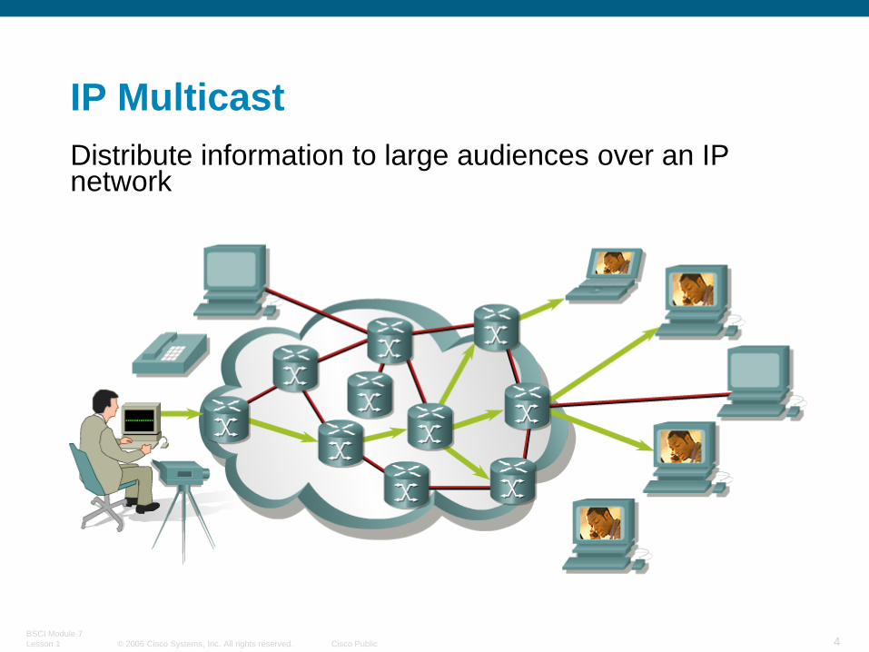
IP Multicast
Distribute information to large audiences over an IP network

© 2006 Cisco Systems, Inc. All rights reserved. Cisco Public
BSCI Module 7
Lesson 1 5
Multicast Advantages
Enhanced efficiency: Controls network traffic and reduces server and CPU loads
Optimized performance: Eliminates traffic redundancy
Distributed applications: Makes multipoint applications possible
For the equivalent amount of multicast traffic, the sender needs much less processing power and bandwidth.
Multicast packets do not impose as high a rate of bandwidth utilization as unicast packets, so there is a greater possibility that they will arrive almost simultaneously at the receivers.

© 2006 Cisco Systems, Inc. All rights reserved. Cisco Public
BSCI Module 7
Lesson 1 6
Multicast Disadvantages
Multicast is UDP-based.
Best-effort delivery
Heavy drops in Voice traffic
Moderate to Heavy drops in Video
No congestion avoidance
Duplicate packets may be generated
Out-of-sequence delivery may occur
Efficiency issues in filtering and in security
© 2006 Cisco Systems, Inc. All rights reserved. Cisco Public
BSCI Module 7
Lesson 1 7
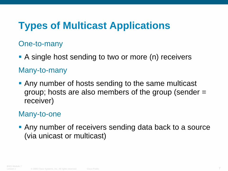
Types of Multicast Applications
One-to-many
A single host sending to two or more (n) receivers
Many-to-many
Any number of hosts sending to the same multicast group; hosts are also members of the group (sender = receiver)
Many-to-one
Any number of receivers sending data back to a source (via unicast or multicast)

© 2006 Cisco Systems, Inc. All rights reserved. Cisco Public
BSCI Module 7
Lesson 1 8
Corporate Broadcasts
Training
Real-Time Data Delivery—Financial
Live TV and Radio Broadcast
to the Desktop
IP Multicast Applications

© 2006 Cisco Systems, Inc. All rights reserved. Cisco Public
BSCI Module 7
Lesson 1 9
Multicast Addressing

© 2006 Cisco Systems, Inc. All rights reserved. Cisco Public
BSCI Module 7
Lesson 1 10
IP Multicast Address Structure
IP group addresses:
Class D address (high-order three bits are set)
Range from 224.0.0.0 through 239.255.255.255

© 2006 Cisco Systems, Inc. All rights reserved. Cisco Public
BSCI Module 7
Lesson 1 11
Multicast Addressing
IPv4 Header
Options Padding
Time to Live Protocol Header Checksum
Identification Flags Fragment Offset
Version IHL Type of Service Total Length
Source Address
Destination AddressDestination
Source
224.0.0.0 - 239.255.255.255 (Class D) Multicast Group Address RangeDestination
1.0.0.0 - 223.255.255.255 (Class A, B, C)Source

© 2006 Cisco Systems, Inc. All rights reserved. Cisco Public
BSCI Module 7
Lesson 1 12
IP Multicast Address Groups
Local scope addresses
224.0.0.0 to 224.0.0.255
Global scope addresses
224.0.1.0 to 238.255.255.255
Administratively scoped addresses
239.0.0.0 to 239.255.255.255

© 2006 Cisco Systems, Inc. All rights reserved. Cisco Public
BSCI Module 7
Lesson 1 13
Local Scope Addresses
Well-known addresses assigned by IANA
Reserved use: 224.0.0.0 through 224.0.0.255
224.0.0.1 (all multicast systems on subnet)
224.0.0.2 (all routers on subnet)
224.0.0.4 (all DVMRP routers)
224.0.0.13 (all PIMv2 routers)
224.0.0.5, 224.0.0.6, 224.0.0.9, and 224.0.0.10 used by unicast routing protocols

© 2006 Cisco Systems, Inc. All rights reserved. Cisco Public
BSCI Module 7
Lesson 1 14
Global Scope Addresses
Transient addresses, assigned and reclaimed dynamically (within applications):
Global range: 224.0.1.0-238.255.255.255
224.2.X.X usually used in MBONE applications
Part of a global scope recently used for new protocols and temporary usage

© 2006 Cisco Systems, Inc. All rights reserved. Cisco Public
BSCI Module 7
Lesson 1 15
Administratively Scoped Addresses
Transient addresses, assigned and reclaimed dynamically (within applications):
Limited (local) scope: 239.0.0.0/8 for private IP multicast addresses (RFC-2365)
Site-local scope: 239.255.0.0/16
Organization-local scope: 239.192.0.0 to 239.251.255.255
© 2006 Cisco Systems, Inc. All rights reserved. Cisco Public
BSCI Module 7
Lesson 1 16
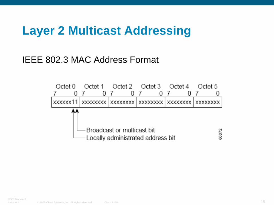
Layer 2 Multicast Addressing
IEEE 802.3 MAC Address Format

© 2006 Cisco Systems, Inc. All rights reserved. Cisco Public
BSCI Module 7
Lesson 1 17
IANA Ethernet MAC Address Range
01-00-5e-00-00-00
through
01-00-5e-7f-ff-ff
Available range of MAC addresses for IP multicast
© 2006 Cisco Systems, Inc. All rights reserved. Cisco Public
BSCI Module 7
Lesson 1 18
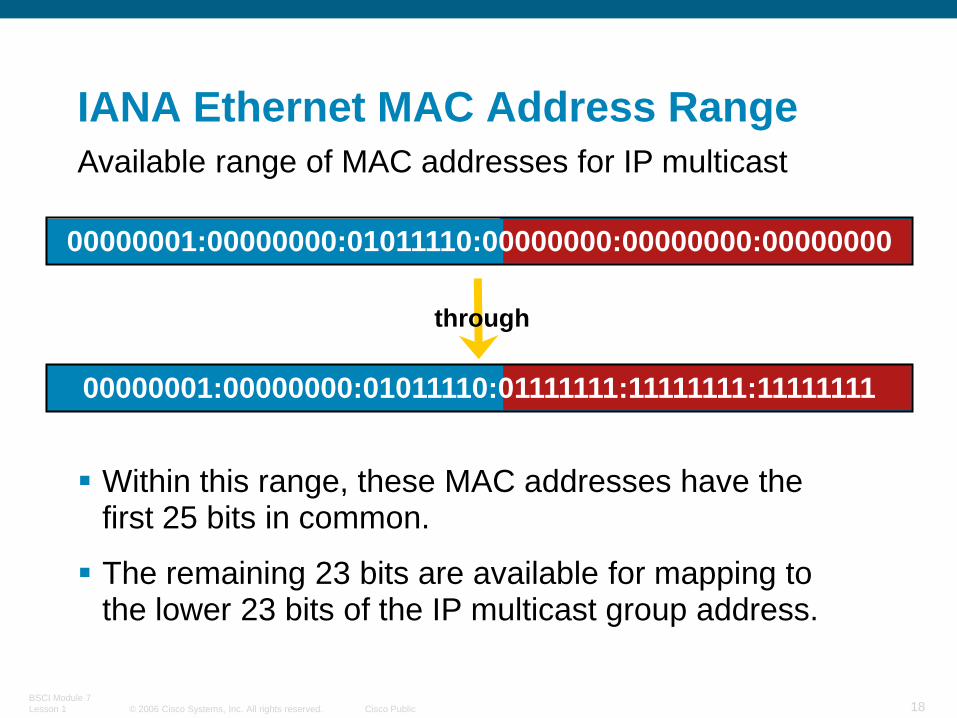
00000001:00000000:01011110:00000000:00000000:00000000
IANA Ethernet MAC Address Range
through
Within this range, these MAC addresses have the first 25 bits in common.
The remaining 23 bits are available for mapping to the lower 23 bits of the IP multicast group address.
Available range of MAC addresses for IP multicast
00000001:00000000:01011110:01111111:11111111:11111111

© 2006 Cisco Systems, Inc. All rights reserved. Cisco Public
BSCI Module 7
Lesson 1 19
Ethernet MAC Address Mapping

© 2006 Cisco Systems, Inc. All rights reserved. Cisco Public
BSCI Module 7
Lesson 1 20
224.1.1.1
224.129.1.1
225.1.1.1
225.129.1.1...
238.1.1.1
238.129.1.1
239.1.1.1
239.129.1.1
0x0100.5E01.0101
1 - Multicast MAC Address
(FDDI and Ethernet)
32 - IP Multicast Addresses
Multicast Addressing
Be Aware of the 32:1 Address Overlap
IP Multicast MAC Address Mapping
(FDDI & Ethernet)

© 2006 Cisco Systems, Inc. All rights reserved. Cisco Public
BSCI Module 7
Lesson 1 21
BSCI Module 7 Lesson 2
IP Multicasting: IGMP and Layer 2 Issues

© 2006 Cisco Systems, Inc. All rights reserved. Cisco Public
BSCI Module 7
Lesson 1 22
Internet Group Management Protocol (IGMP)
How hosts tell routers about group membership
Routers solicit group membership from directly connected hosts
–RFC 1112 specifies IGMPv1
• Supported on Windows 95
–RFC 2236 specifies IGMPv2
•Supported on latest service pack for Windows and most UNIX systems
–RFC 3376 specifies IGMPv3
•Supported in Window XP and various UNIX systems
© 2006 Cisco Systems, Inc. All rights reserved. Cisco Public
BSCI Module 7
Lesson 1 23
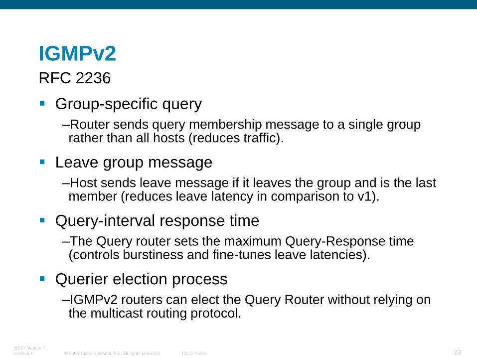
IGMPv2RFC 2236
Group-specific query
–Router sends query membership message to a single group rather than all hosts (reduces traffic).
Leave group message
–Host sends leave message if it leaves the group and is the last member (reduces leave latency in comparison to v1).
Query-interval response time
–The Query router sets the maximum Query-Response time (controls burstiness and fine-tunes leave latencies).
Querier election process
–IGMPv2 routers can elect the Query Router without relying on the multicast routing protocol.
© 2006 Cisco Systems, Inc. All rights reserved. Cisco Public
BSCI Module 7
Lesson 1 24
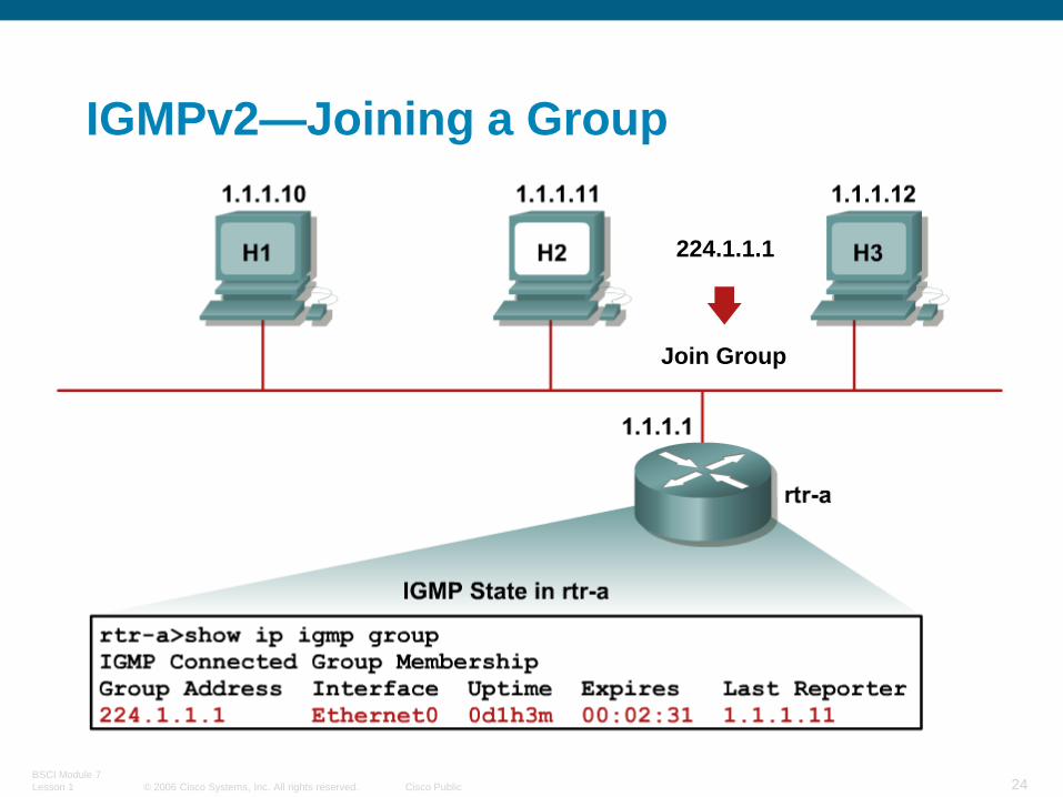
IGMPv2—Joining a Group
224.1.1.1
Join Group
© 2006 Cisco Systems, Inc. All rights reserved. Cisco Public
BSCI Module 7
Lesson 1 25
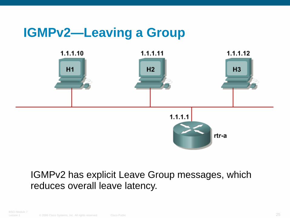
IGMPv2—Leaving a Group
IGMPv2 has explicit Leave Group messages, which reduces overall leave latency.

© 2006 Cisco Systems, Inc. All rights reserved. Cisco Public
BSCI Module 7
Lesson 1 26
IGMPv2—Leaving a Group (Cont.)
Hosts H2 and H3 are members of group 224.1.1.1.
1. H2 sends a leave message.

© 2006 Cisco Systems, Inc. All rights reserved. Cisco Public
BSCI Module 7
Lesson 1 27
IGMPv2—Leaving a Group (Cont.)
2. Router sends group-specific query.

© 2006 Cisco Systems, Inc. All rights reserved. Cisco Public
BSCI Module 7
Lesson 1 28
IGMPv2—Leaving a Group (Cont.)
3. A remaining member host sends report, so group remains active.

© 2006 Cisco Systems, Inc. All rights reserved. Cisco Public
BSCI Module 7
Lesson 1 29
IGMPv2—Leaving a Group (Cont.)

© 2006 Cisco Systems, Inc. All rights reserved. Cisco Public
BSCI Module 7
Lesson 1 30
IGMPv2—Leaving a Group (Cont.)

© 2006 Cisco Systems, Inc. All rights reserved. Cisco Public
BSCI Module 7
Lesson 1 31
IGMPv3—Joining a Group
Joining member sends IGMPv3 report to 224.0.0.22 immediately upon joining.

© 2006 Cisco Systems, Inc. All rights reserved. Cisco Public
BSCI Module 7
Lesson 1 32
IGMPv3—Joining Specific Source(s)
IGMPv3 Report contains desired sources in the Include list. Only “Included” sources are joined.

© 2006 Cisco Systems, Inc. All rights reserved. Cisco Public
BSCI Module 7
Lesson 1 33
IGMPv3—Maintaining State
Router sends periodic queries:
All IGMPv3 members respond.
–Reports contain multiple group state records.

© 2006 Cisco Systems, Inc. All rights reserved. Cisco Public
BSCI Module 7
Lesson 1 34
IGMP Layer 2 Issues

© 2006 Cisco Systems, Inc. All rights reserved. Cisco Public
BSCI Module 7
Lesson 1 35
Determining IGMP Version Running
Determining which IGMP version is running on an
interface.
rtr-a>show ip igmp interface e0
Ethernet0 is up, line protocol is up
Internet address is 1.1.1.1, subnet mask is 255.255.255.0
IGMP is enabled on interface
Current IGMP version is 2
CGMP is disabled on interface
IGMP query interval is 60 seconds
IGMP querier timeout is 120 seconds
IGMP max query response time is 10 seconds
Inbound IGMP access group is not set
Multicast routing is enabled on interface
Multicast TTL threshold is 0
Multicast designated router (DR) is 1.1.1.1 (this system)
IGMP querying router is 1.1.1.1 (this system)
Multicast groups joined: 224.0.1.40 224.2.127.254

© 2006 Cisco Systems, Inc. All rights reserved. Cisco Public
BSCI Module 7
Lesson 1 36
Layer 2 Multicast Frame Switching
Problem: Layer 2 flooding of multicast
frames
Typical Layer 2 switches treat multicast traffic as unknown or broadcast and must flood the frame to every port (in VLAN).
Static entries may sometimes be set to specify which ports receive which groups of multicast traffic.
Dynamic configuration of these entries may reduce administration.

© 2006 Cisco Systems, Inc. All rights reserved. Cisco Public
BSCI Module 7
Lesson 1 37
Layer 2 Multicast Switching Solutions
Cisco Group Management Protocol (CGMP): Simple, proprietary; routers and switches
IGMP snooping: Complex, standardized, proprietary implementations; switches only

© 2006 Cisco Systems, Inc. All rights reserved. Cisco Public
BSCI Module 7
Lesson 1 38
Layer 2 Multicast Frame Switching CGMPSolution 1: CGMP
Runs on switches and routers.
CGMP packets sent by routers to switches at the CGMP multicast MAC address of 0100.0cdd.dddd.
CGMP packet contains:
• Type field: join or leave
• MAC address of the IGMP client
• Multicast MAC address of the group
Switch uses CGMP packet information to add or remove an entry for a particular multicast MAC address.
© 2006 Cisco Systems, Inc. All rights reserved. Cisco Public
BSCI Module 7
Lesson 1 39
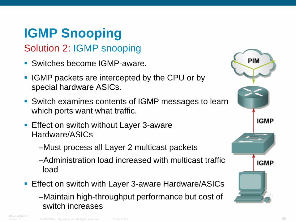
IGMP SnoopingSolution 2: IGMP snooping
Switches become IGMP-aware.
IGMP packets are intercepted by the CPU or by special hardware ASICs.
Switch examines contents of IGMP messages to learn which ports want what traffic.
Effect on switch without Layer 3-aware Hardware/ASICs
–Must process all Layer 2 multicast packets
–Administration load increased with multicast traffic load
Effect on switch with Layer 3-aware Hardware/ASICs
–Maintain high-throughput performance but cost of switch increases
© 2006 Cisco Systems, Inc. All rights reserved. Cisco Public
BSCI Module 7
Lesson 1 40
Impact of IGMPv3 on IGMP Snooping
– IGMPv3 Reports are sent to a separate group (224.0.0.22) reduces load on switch CPU
– No Report Suppression in IGMPv3
IGMP Snooping should not cause a serious performance problem once IGMPv3 is implemented.
IGMPv3 and IGMP Snooping

© 2006 Cisco Systems, Inc. All rights reserved. Cisco Public
BSCI Module 7
Lesson 1 41
Multicast Distribution Trees

© 2006 Cisco Systems, Inc. All rights reserved. Cisco Public
BSCI Module 7
Lesson 1 42
Multicast Protocol Basics
Types of multicast distribution trees:
Source distribution trees; also called shortest pathtrees (SPTs)
Shared distribution trees; rooted at a meeting point in the network
– A core router serves as a rendezvous point (RP)

© 2006 Cisco Systems, Inc. All rights reserved. Cisco Public
BSCI Module 7
Lesson 1 43
Shortest Path or Source Distribution Tree
Receiver 1
B
E
A D F
Source 1Notation: (S, G)
S = Source
G = Group
C
Receiver 2
Source 2
Multicast Distribution Trees

© 2006 Cisco Systems, Inc. All rights reserved. Cisco Public
BSCI Module 7
Lesson 1 44
Receiver 1
B
E
A D F
Source 1Notation: (S, G)
S = Source
G = Group
C
Receiver 2
Source 2
Multicast Distribution Trees
Shortest Path or Source Distribution Tree

© 2006 Cisco Systems, Inc. All rights reserved. Cisco Public
BSCI Module 7
Lesson 1 45
Multicast Distribution Trees
Receiver 1
B
E
A D F
Notation: (*, G)
* = All Sources
G = Group
C
Receiver 2
(RP) PIM Rendezvous Point
Shared Tree
(RP)
Shared Distribution Tree

© 2006 Cisco Systems, Inc. All rights reserved. Cisco Public
BSCI Module 7
Lesson 1 46
Multicast Distribution Trees
Receiver 1
B
E
A F
Source 1 Notation: (*, G)
* = All Sources
G = Group
C
Receiver 2
Source 2
(RP) PIM Rendezvous Point
Shared Tree
Source Tree
D (RP)
Shared Distribution Tree

© 2006 Cisco Systems, Inc. All rights reserved. Cisco Public
BSCI Module 7
Lesson 1 47
Multicast Distribution Tree Identification
(S,G) entries
For this particular source sending to this particular group
Traffic is forwarded through the shortest path from the source
(*,G) entries
For any (*) source sending to this group
Traffic is forwarded through a meeting point for this group
© 2006 Cisco Systems, Inc. All rights reserved. Cisco Public
BSCI Module 7
Lesson 1 48
Multicast Distribution Trees
Characteristics of Distribution Trees
Source or Shortest Path trees
Uses more memory but optimal paths from source to all receivers; minimizes delay
Shared trees
Uses less memory but sub-optimal paths from source to all receivers; may introduce extra delay

© 2006 Cisco Systems, Inc. All rights reserved. Cisco Public
BSCI Module 7
Lesson 1 49
Multicast Routing

© 2006 Cisco Systems, Inc. All rights reserved. Cisco Public
BSCI Module 7
Lesson 1 50
Protocols for IP Multicast Routing
PIM is used between routers so that they can track which multicast packets to forward to each other and to their directly connected LANs.
© 2006 Cisco Systems, Inc. All rights reserved. Cisco Public
BSCI Module 7
Lesson 1 51
Protocol-Independent Multicast (PIM)
PIM maintains the current IP multicast service mode of receiver-initiated membership.
PIM is not dependent on a specific unicast routing protocol.
With PIM, routers maintain forwarding tables to forward multicast datagrams.
PIM can operate in dense mode or sparse mode.
–Dense mode protocols flood multicast traffic to all parts of the network and prune the flows where there are no receivers using a periodic flood-and-prune mechanism.
–Sparse mode protocols use an explicit join mechanism where distribution trees are built on demand by explicit tree join messages sent by routers that have directly connected receivers.
© 2006 Cisco Systems, Inc. All rights reserved. Cisco Public
BSCI Module 7
Lesson 1 52
Multicast Tree Creation
PIM Join/Prune Control Messages
Used to create/remove Distribution Trees
Shortest Path trees
PIM control messages are sent toward the Source
Shared trees
PIM control messages are sent toward RP

© 2006 Cisco Systems, Inc. All rights reserved. Cisco Public
BSCI Module 7
Lesson 1 53
Multicast Forwarding
Multicast routing operation is the opposite of unicast routing.
Unicast routing is concerned with where the packet is going.
Multicast routing is concerned with where the packet comes from.
Multicast routing uses Reverse Path Forwarding (RPF) to prevent forwarding loops.

© 2006 Cisco Systems, Inc. All rights reserved. Cisco Public
BSCI Module 7
Lesson 1 54
Reverse Path Forwarding (RPF)
The RPF Calculation
The multicast source address is checked against the unicast routing table.
This determines the interface and upstream router in the direction of the source to which PIM Joins are sent.
This interface becomes the “Incoming” or RPF interface.
–A router forwards a multicast datagram only if received on the RPF interface.
© 2006 Cisco Systems, Inc. All rights reserved. Cisco Public
BSCI Module 7
Lesson 1 55
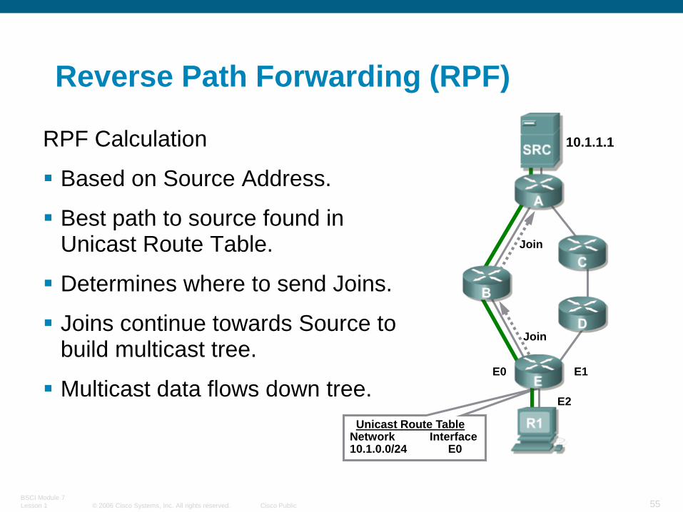
Reverse Path Forwarding (RPF)
RPF Calculation
Based on Source Address.
Best path to source found in Unicast Route Table.
Determines where to send Joins.
Joins continue towards Source to build multicast tree.
Multicast data flows down tree.
10.1.1.1
E1
E2
Unicast Route TableNetwork Interface10.1.0.0/24 E0
Join
Join
E0

© 2006 Cisco Systems, Inc. All rights reserved. Cisco Public
BSCI Module 7
Lesson 1 56
Reverse Path Forwarding (RPF)
10.1.1.1
E1E0
E2
Join
Join
RPF Calculation (cont.)
Repeat for other receivers…

© 2006 Cisco Systems, Inc. All rights reserved. Cisco Public
BSCI Module 7
Lesson 1 57
Reverse Path Forwarding (RPF)
RPF Calculation
What if we have equal-cost paths?
–We can’t use both.
Tie-Breaker
–Use highest Next-Hop IP address.
10.1.1.1
E1E0
E2Unicast Route Table
Network Intfc Nxt-Hop10.1.0.0/24 E0 1.1.1.110.1.0.0/24 E1 1.1.2.1
1.1.2.11.1.1.1Join

© 2006 Cisco Systems, Inc. All rights reserved. Cisco Public
BSCI Module 7
Lesson 1 58
Multicast Distribution Tree Creation
Shared Tree Example

© 2006 Cisco Systems, Inc. All rights reserved. Cisco Public
BSCI Module 7
Lesson 1 59
PIM Dense Mode Operation

© 2006 Cisco Systems, Inc. All rights reserved. Cisco Public
BSCI Module 7
Lesson 1 60
PIM-DM Flood and Prune
Initial Flooding
© 2006 Cisco Systems, Inc. All rights reserved. Cisco Public
BSCI Module 7
Lesson 1 61
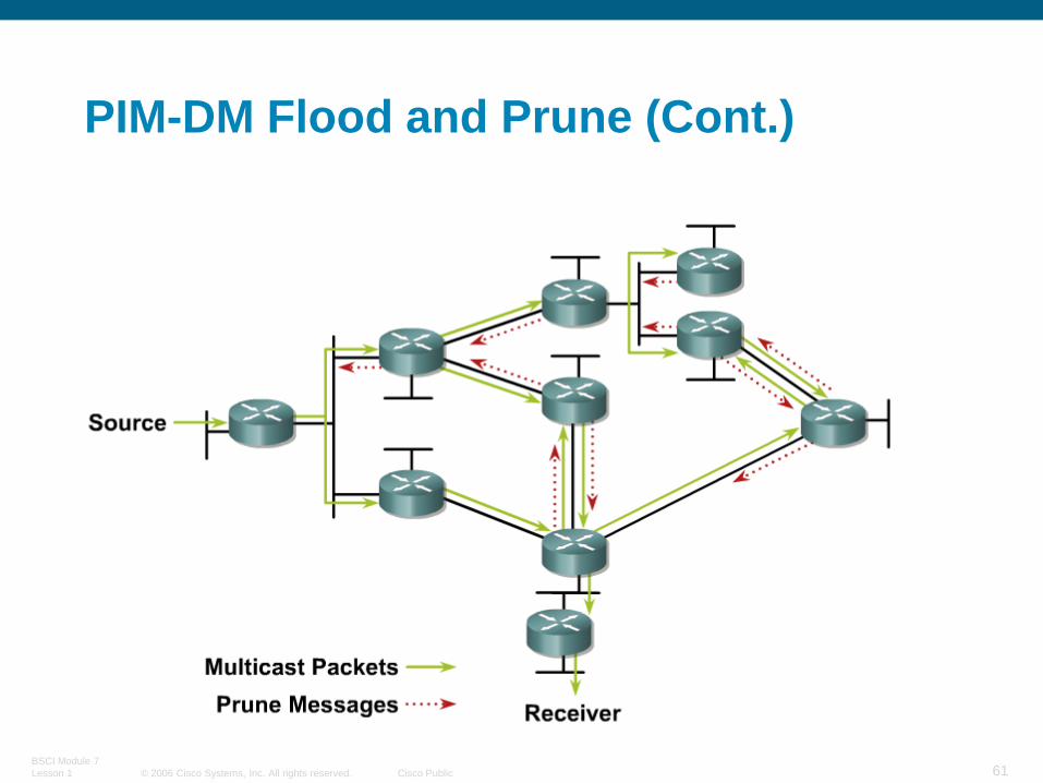
PIM-DM Flood and Prune (Cont.)

© 2006 Cisco Systems, Inc. All rights reserved. Cisco Public
BSCI Module 7
Lesson 1 62
PIM-DM Flood and Prune (Cont.)
Results After Pruning

© 2006 Cisco Systems, Inc. All rights reserved. Cisco Public
BSCI Module 7
Lesson 1 63
PIM Sparse Mode Operation

© 2006 Cisco Systems, Inc. All rights reserved. Cisco Public
BSCI Module 7
Lesson 1 64
PIM Sparse Mode
PIM-SM works with any of the underlying unicast routing protocols.
PIM-SM supports both source and shared trees.
PIM-SM is based on an explicit pull model.
PIM-SM uses an RP.
–Senders and receivers “meet each other.”
–Senders are registered with RP by their first-hop router.
–Receivers are joined to the shared tree (rooted at the RP) by their local DR.
© 2006 Cisco Systems, Inc. All rights reserved. Cisco Public
BSCI Module 7
Lesson 1 65
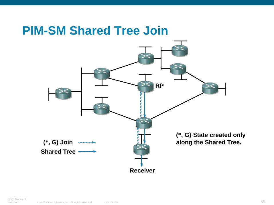
PIM-SM Shared Tree Join
Receiver
RP
(*, G) Join
Shared Tree
(*, G) State created only
along the Shared Tree.
© 2006 Cisco Systems, Inc. All rights reserved. Cisco Public
BSCI Module 7
Lesson 1 66
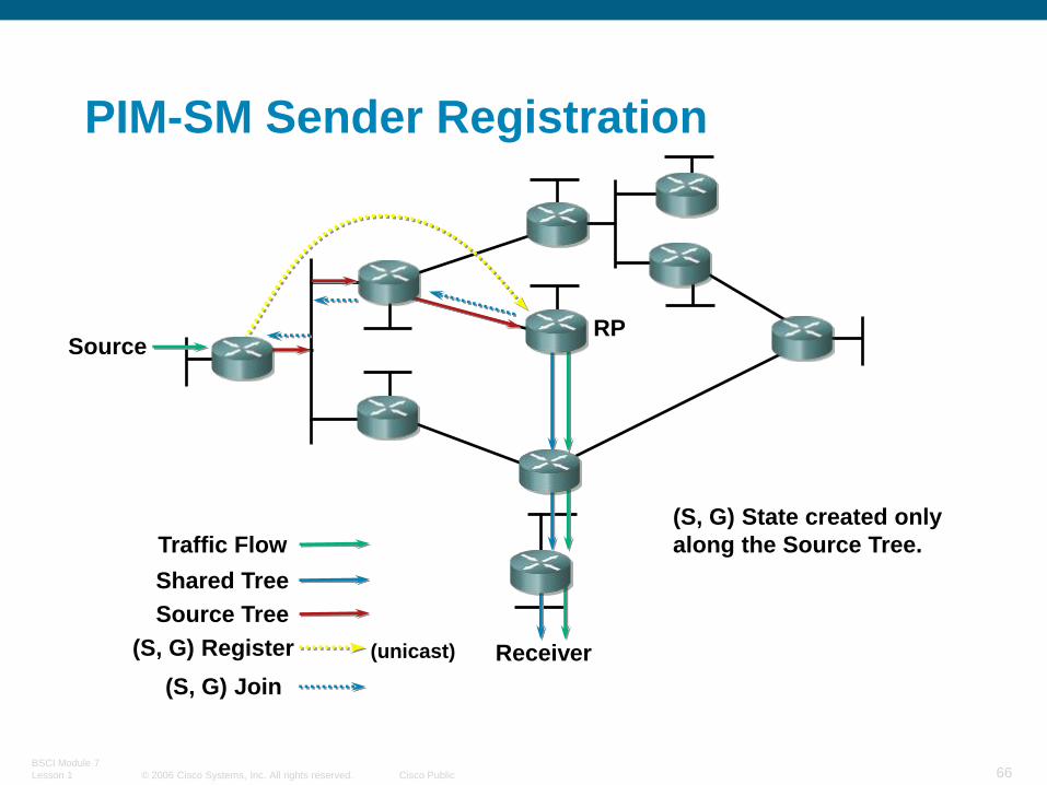
PIM-SM Sender Registration
Receiver
RP
(S, G) Join
Source
Shared Tree
(S, G) Register (unicast)
Source Tree
(S, G) State created only
along the Source Tree.Traffic Flow
© 2006 Cisco Systems, Inc. All rights reserved. Cisco Public
BSCI Module 7
Lesson 1 67
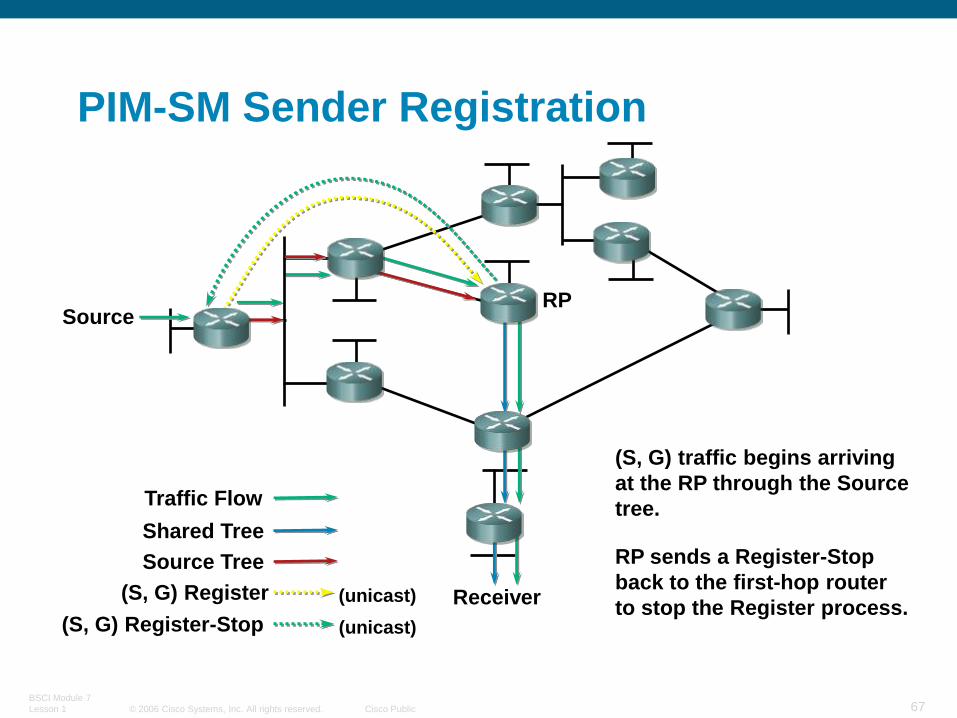
PIM-SM Sender Registration
Receiver
RPSource
Shared Tree
Source Tree RP sends a Register-Stop
back to the first-hop router
to stop the Register process.(S, G) Register-Stop (unicast)
Traffic Flow
(S, G) Register (unicast)
(S, G) traffic begins arriving
at the RP through the Source
tree.
© 2006 Cisco Systems, Inc. All rights reserved. Cisco Public
BSCI Module 7
Lesson 1 68
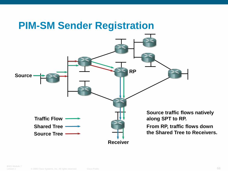
PIM-SM Sender Registration
Receiver
RPSource
Shared Tree
Source Tree
Traffic Flow
Source traffic flows natively
along SPT to RP.
From RP, traffic flows down
the Shared Tree to Receivers.
© 2006 Cisco Systems, Inc. All rights reserved. Cisco Public
BSCI Module 7
Lesson 1 69
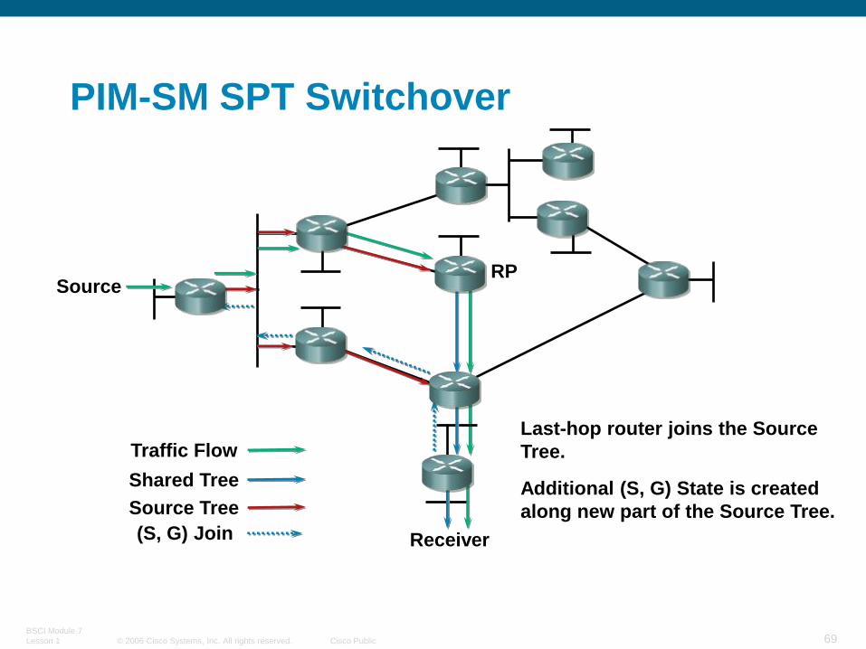
PIM-SM SPT Switchover
Receiver
RP
(S, G) Join
Source
Source Tree
Shared Tree
Last-hop router joins the Source
Tree.
Additional (S, G) State is created
along new part of the Source Tree.
Traffic Flow
© 2006 Cisco Systems, Inc. All rights reserved. Cisco Public
BSCI Module 7
Lesson 1 70
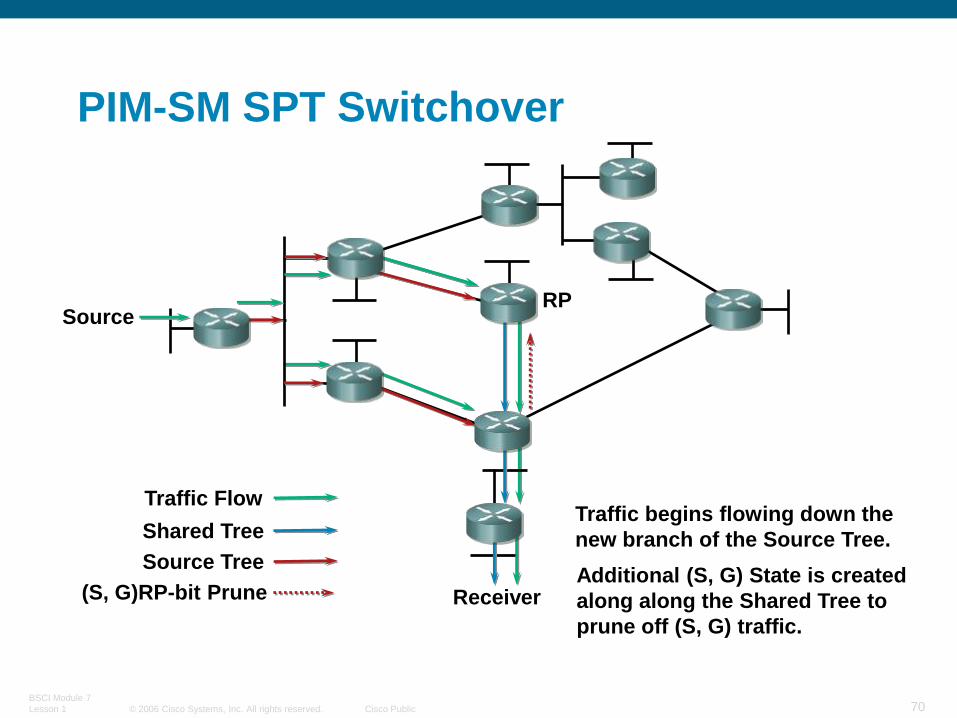
PIM-SM SPT Switchover
Receiver
RPSource
Source Tree
Shared Tree
(S, G)RP-bit Prune
Traffic begins flowing down the
new branch of the Source Tree.
Additional (S, G) State is created
along along the Shared Tree to
prune off (S, G) traffic.
Traffic Flow
© 2006 Cisco Systems, Inc. All rights reserved. Cisco Public
BSCI Module 7
Lesson 1 71
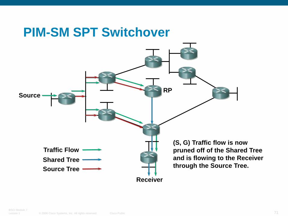
PIM-SM SPT Switchover
Receiver
RPSource
Source Tree
Shared Tree
(S, G) Traffic flow is now
pruned off of the Shared Tree
and is flowing to the Receiver
through the Source Tree.
Traffic Flow

© 2006 Cisco Systems, Inc. All rights reserved. Cisco Public
BSCI Module 7
Lesson 1 72
PIM-SM SPT Switchover
Receiver
RPSource
Source Tree
Shared Tree
(S, G) traffic flow is no longer
needed by the RP so it Prunes
the flow of (S, G) traffic.
Traffic Flow
(S, G) Prune
© 2006 Cisco Systems, Inc. All rights reserved. Cisco Public
BSCI Module 7
Lesson 1 73
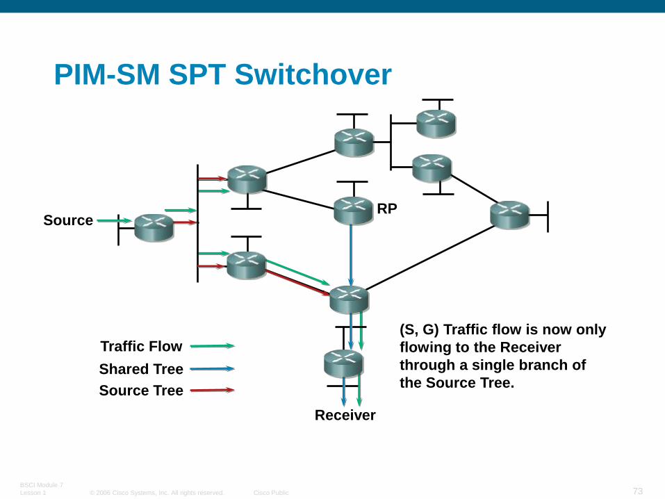
PIM-SM SPT Switchover
Receiver
RPSource
Source Tree
Shared Tree
(S, G) Traffic flow is now only
flowing to the Receiver
through a single branch of
the Source Tree.
Traffic Flow

© 2006 Cisco Systems, Inc. All rights reserved. Cisco Public
BSCI Module 7
Lesson 1 74
“The default behavior of PIM-SM is that routers with directly connected members will join the Shortest Path Tree as soon as they detect a new multicast source.”
PIM-SM Frequently Forgotten Fact

© 2006 Cisco Systems, Inc. All rights reserved. Cisco Public
BSCI Module 7
Lesson 1 75
PIM-SM Evaluation
Effective for Sparse or Dense distribution of multicast receivers
Advantages:
Traffic only sent down “joined” branches
Can switch to optimal source-trees for high traffic sources dynamically
Unicast routing protocol-independent
Basis for inter-domain multicast routing

© 2006 Cisco Systems, Inc. All rights reserved. Cisco Public
BSCI Module 7
Lesson 1 76
Multiple RPs with Auto RP
PIM Sparse-Dense-Mode

© 2006 Cisco Systems, Inc. All rights reserved. Cisco Public
BSCI Module 7
Lesson 1 77
Impact of IGMPv3 on IGMP Snooping
– IGMPv3 Reports are sent to a separate group (224.0.0.22) reduces load on switch CPU
– No Report Suppression in IGMPv3
IGMP Snooping should not cause a serious performance problem once IGMPv3 is implemented.
IGMPv3 and IGMP Snooping