Embed Size (px)
Citation preview
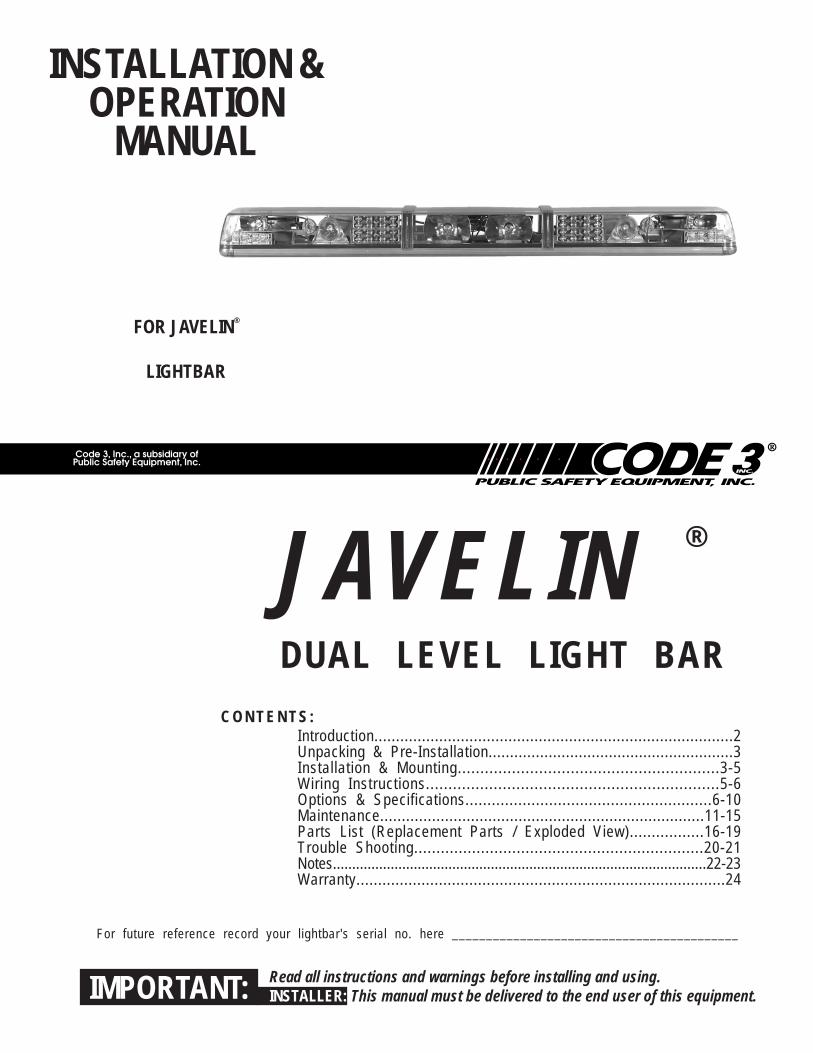
INSTALLATION &OPERATION
MANUAL
FOR JAVELIN®
LIGHTBAR
Read all instructions and warnings before installing and using.INSTALLER: This manual must be delivered to the end user of this equipment.IMPORTANT:
JAVELIN ®
DUAL LEVEL LIGHT BAR
Introduction...................................................................................2Unpacking & Pre-Installation.........................................................3Installation & Mounting..........................................................3-5Wiring Instructions.................................................................5-6Options & Specifications........................................................6-10Maintenance...........................................................................11-15Parts List (Replacement Parts / Exploded View).................16-19Trouble Shooting.................................................................20-21Notes.................................................................................................22-23Warranty.....................................................................................24
C O N T E N T S :
For future reference record your lightbar's serial no. here __________________________________________
2
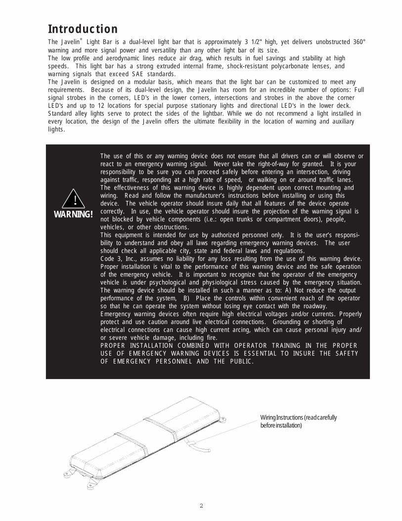
Introduct ionThe Javelin® Light Bar is a dual-level light bar that is approximately 3 1/2" high, yet delivers unobstructed 360°warning and more signal power and versatility than any other light bar of its size.The low profile and aerodynamic lines reduce air drag, which results in fuel savings and stability at highspeeds. This light bar has a strong extruded internal frame, shock-resistant polycarbonate lenses, andwarning signals that exceed SAE standards.The Javelin is designed on a modular basis, which means that the light bar can be customized to meet anyrequirements. Because of its dual-level design, the Javelin has room for an incredible number of options: Fullsignal strobes in the corners, LED's in the lower corners, intersections and strobes in the above the cornerLED's and up to 12 locations for special purpose stationary lights and directional LED's in the lower deck.Standard alley lights serve to protect the sides of the lightbar. While we do not recommend a light installed inevery location, the design of the Javelin offers the ultimate flexibility in the location of warning and auxiliaryl ights.
The use of this or any warning device does not ensure that all drivers can or will observe orreact to an emergency warning signal. Never take the right-of-way for granted. It is yourresponsibility to be sure you can proceed safely before entering an intersection, drivingagainst traffic, responding at a high rate of speed, or walking on or around traffic lanes.The effectiveness of this warning device is highly dependent upon correct mounting andwiring. Read and follow the manufacturer’s instructions before installing or using thisdevice. The vehicle operator should insure daily that all features of the device operatecorrectly. In use, the vehicle operator should insure the projection of the warning signal isnot blocked by vehicle components (i.e.: open trunks or compartment doors), people,vehicles, or other obstructions.This equipment is intended for use by authorized personnel only. It is the user’s responsi-bility to understand and obey all laws regarding emergency warning devices. The usershould check all applicable city, state and federal laws and regulations.Code 3, Inc., assumes no liability for any loss resulting from the use of this warning device.Proper installation is vital to the performance of this warning device and the safe operationof the emergency vehicle. It is important to recognize that the operator of the emergencyvehicle is under psychological and physiological stress caused by the emergency situation.The warning device should be installed in such a manner as to: A) Not reduce the outputperformance of the system, B) Place the controls within convenient reach of the operatorso that he can operate the system without losing eye contact with the roadway.Emergency warning devices often require high electrical voltages and/or currents. Properlyprotect and use caution around live electrical connections. Grounding or shorting ofelectrical connections can cause high current arcing, which can cause personal injury and/or severe vehicle damage, including fire.PROPER INSTALLATION COMBINED WITH OPERATOR TRAINING IN THE PROPERUSE OF EMERGENCY WARNING DEVICES IS ESSENTIAL TO INSURE THE SAFETYOF EMERGENCY PERSONNEL AND THE PUBLIC.
WARNING!!
Wiring Instructions (read carefullybefore installation)
3
Unpacking & Pre-installationCarefully remove the light bar and place it on a flat surface, taking care not to scratch the lenses or damagethe cable coming out of the bottom. Examine the unit for transit damage, broken lamps, etc. Report anydamage to the carrier and keep the shipping carton.
Standard light bars are built to operate on 12 volt D.C. negative ground (earth) vehicles. If you have anelectrical system other than 12 volt D.C. negative ground (earth), and have not ordered a specially wired lightbar, contact the factory for instructions.
Test the unit before installation. To test, touch the black wire to the ground (earth) and the other wires to +12volts D.C., in accordance with the instructions attached to the cable (an automotive battery is preferable forthis test). A battery charger may be used, but please note that some electronic options (flashers, StingRays ,etc.) may not operate normally when powered by a battery charger. If problems occur at this point, contact thefactory.
Installation & Mounting
MOUNTING HARDWARE - All mounting hardware is packed in a small box inside the main carton. Fourstandard kits are available: (1) Hook-On Type, (1) Tow and Recovery and (2) Permanent Types. These arediscussed in detail later. Note: Hook-on mounting for "gutterless" type vehicles will require a special hook formounting. Several special application hooks are available. Contact the factory for details.
Utilizing non-factory supplied screws and/or mounting brackets and/or theimproper number of screws may result in loss of warranty coverage on theequ ipment .
WARNING! !
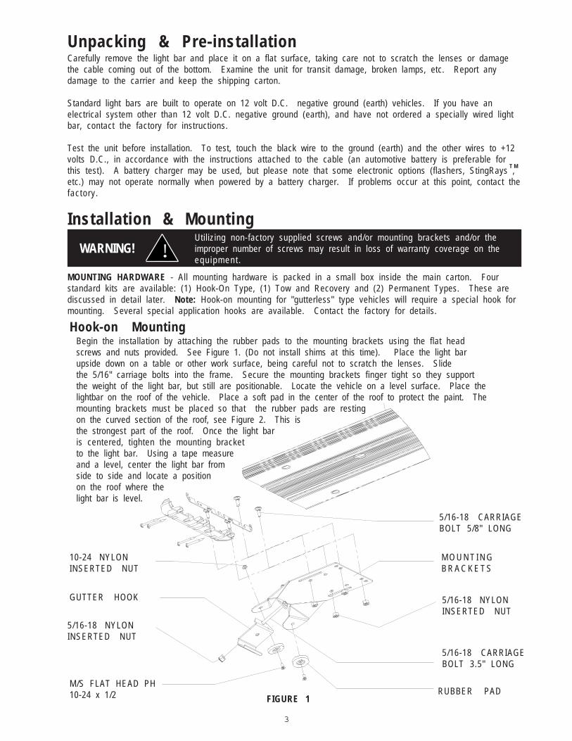
Hook-on MountingBegin the installation by attaching the rubber pads to the mounting brackets using the flat headscrews and nuts provided. See Figure 1. (Do not install shims at this time). Place the light barupside down on a table or other work surface, being careful not to scratch the lenses. Slidethe 5/16" carriage bolts into the frame. Secure the mounting brackets finger tight so they supportthe weight of the light bar, but still are positionable. Locate the vehicle on a level surface. Place thelightbar on the roof of the vehicle. Place a soft pad in the center of the roof to protect the paint. Themounting brackets must be placed so that the rubber pads are restingon the curved section of the roof, see Figure 2. This isthe strongest part of the roof. Once the light baris centered, tighten the mounting bracketto the light bar. Using a tape measureand a level, center the light bar fromside to side and locate a positionon the roof where thelight bar is level.
FIGURE 1
M/S FLAT HEAD PH10-24 x 1/2
5/16-18 NYLONINSERTED NUT
10-24 NYLONINSERTED NUT
5/16-18 NYLONINSERTED NUT
GUTTER HOOK
M O U N T I N GB R A C K E T S
5/16-18 CARRIAGEBOLT 5/8" LONG
RUBBER PAD
5/16-18 CARRIAGEBOLT 3.5" LONG
T M
4
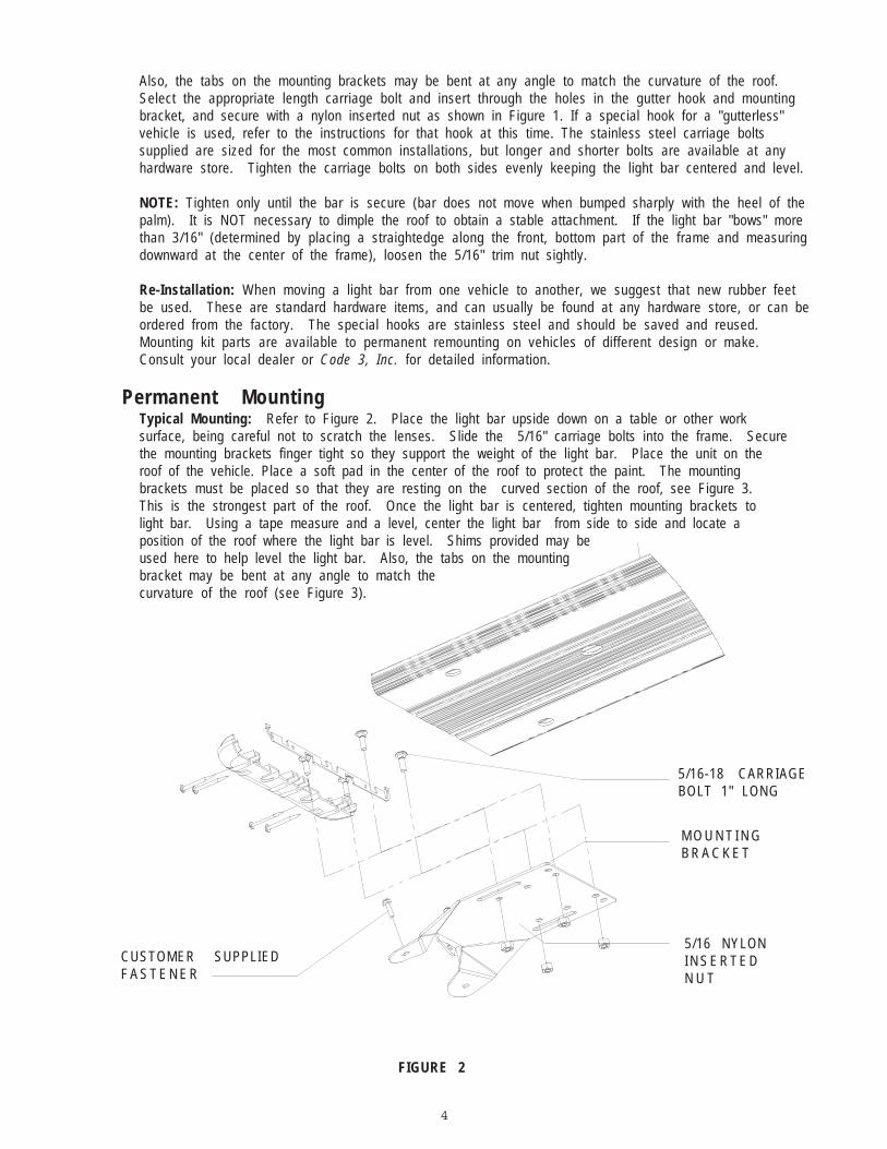
Also, the tabs on the mounting brackets may be bent at any angle to match the curvature of the roof.Select the appropriate length carriage bolt and insert through the holes in the gutter hook and mountingbracket, and secure with a nylon inserted nut as shown in Figure 1. If a special hook for a "gutterless"vehicle is used, refer to the instructions for that hook at this time. The stainless steel carriage boltssupplied are sized for the most common installations, but longer and shorter bolts are available at anyhardware store. Tighten the carriage bolts on both sides evenly keeping the light bar centered and level.
NOTE: Tighten only until the bar is secure (bar does not move when bumped sharply with the heel of thepalm). It is NOT necessary to dimple the roof to obtain a stable attachment. If the light bar "bows" morethan 3/16" (determined by placing a straightedge along the front, bottom part of the frame and measuringdownward at the center of the frame), loosen the 5/16" trim nut sightly.
Re-Installation: When moving a light bar from one vehicle to another, we suggest that new rubber feetbe used. These are standard hardware items, and can usually be found at any hardware store, or can beordered from the factory. The special hooks are stainless steel and should be saved and reused.Mounting kit parts are available to permanent remounting on vehicles of different design or make.Consult your local dealer or Code 3, Inc. for detailed information.
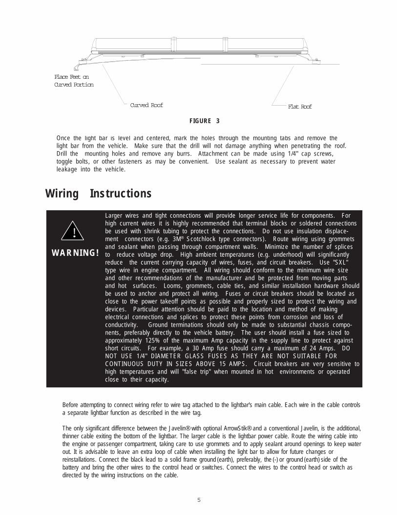
Permanent MountingTypical Mounting: Refer to Figure 2. Place the light bar upside down on a table or other worksurface, being careful not to scratch the lenses. Slide the 5/16" carriage bolts into the frame. Securethe mounting brackets finger tight so they support the weight of the light bar. Place the unit on theroof of the vehicle. Place a soft pad in the center of the roof to protect the paint. The mountingbrackets must be placed so that they are resting on the curved section of the roof, see Figure 3.This is the strongest part of the roof. Once the light bar is centered, tighten mounting brackets tolight bar. Using a tape measure and a level, center the light bar from side to side and locate aposition of the roof where the light bar is level. Shims provided may beused here to help level the light bar. Also, the tabs on the mountingbracket may be bent at any angle to match thecurvature of the roof (see Figure 3).
FIGURE 2
5/16 NYLONI N S E R T E DN U T
M O U N T I N GB R A C K E T
5/16-18 CARRIAGEBOLT 1" LONG
CUSTOMER SUPPLIEDF A S T E N E R
5
Once the light bar is level and centered, mark the holes through the mounting tabs and remove thelight bar from the vehicle. Make sure that the drill will not damage anything when penetrating the roof.Drill the mounting holes and remove any burrs. Attachment can be made using 1/4" cap screws,toggle bolts, or other fasteners as may be convenient. Use sealant as necessary to prevent waterleakage into the vehicle.
Wiring Instructions
Larger wires and tight connections will provide longer service life for components. Forhigh current wires it is highly recommended that terminal blocks or soldered connectionsbe used with shrink tubing to protect the connections. Do not use insulation displace-ment connectors (e.g. 3M® Scotchlock type connectors). Route wiring using grommetsand sealant when passing through compartment walls. Minimize the number of splicesto reduce voltage drop. High ambient temperatures (e.g. underhood) will significantlyreduce the current carrying capacity of wires, fuses, and circuit breakers. Use "SXL"type wire in engine compartment. All wiring should conform to the minimum wire sizeand other recommendations of the manufacturer and be protected from moving partsand hot surfaces. Looms, grommets, cable ties, and similar installation hardware shouldbe used to anchor and protect all wiring. Fuses or circuit breakers should be located asclose to the power takeoff points as possible and properly sized to protect the wiring anddevices. Particular attention should be paid to the location and method of makingelectrical connections and splices to protect these points from corrosion and loss ofconductivity. Ground terminations should only be made to substantial chassis compo-nents, preferably directly to the vehicle battery. The user should install a fuse sized toapproximately 125% of the maximum Amp capacity in the supply line to protect againstshort circuits. For example, a 30 Amp fuse should carry a maximum of 24 Amps. DONOT USE 1/4" DIAMETER GLASS FUSES AS THEY ARE NOT SUITABLE FORCONTINUOUS DUTY IN SIZES ABOVE 15 AMPS. Circuit breakers are very sensitive tohigh temperatures and will "false trip" when mounted in hot environments or operatedclose to their capacity.
W A R N I N G !
!
Before attempting to connect wiring refer to wire tag attached to the lightbar's main cable. Each wire in the cable controlsa separate lightbar function as described in the wire tag.
The only significant difference between the Javelin® with optional ArrowStik® and a conventional Javelin, is the additional,thinner cable exiting the bottom of the lightbar. The larger cable is the lightbar power cable. Route the wiring cable intothe engine or passenger compartment, taking care to use grommets and to apply sealant around openings to keep waterout. It is advisable to leave an extra loop of cable when installing the light bar to allow for future changes orreinstallations. Connect the black lead to a solid frame ground (earth), preferably, the (-) or ground (earth) side of thebattery and bring the other wires to the control head or switches. Connect the wires to the control head or switch asdirected by the wiring instructions on the cable.
Curved Roof Flat Roof
Place Feet onCurved Portion
FIGURE 3
6
OPTIONS & SPECIFICATIONS
This Product contains high intensity LED devices. To prevent eye damage,DO NOT stare into light beam at close range.!
LED WARNING MODULES
WARNING!
OPTIONAL STROBE WIRING INSTRUCTIONS - For all configurations the strobe power supply(s) will be powered by the #14AWG Red and Red/Black wires in the lightbar main cable. For 2 or 4 head configurations only the Red or Red/Black wire will beutilized. For 6, 8, 10 and 12 head configurations both wires will be utilized. These wires will supply DC power to each strobe powersupply(s) so all user supplied switches and wiring connected to the Red and/or Red/Black wires should be rated for a minimum of10 Amps and fused at a maximum of 15 Amps, for each wire used. Two additional wires in the main cable (typically Green andGreen/Black) are used to control the flash mode of the power supply. These wires are low current connections at typically less than1 Amp. (See lightbar "wire tag" for wire color.)
- Refer to the control head manual packaged with the lightbar for control head installation and operation instruction.
Arrowstik® / Narrowstik®
OPTIONAL HALOGEN ARROWSTIK® (7-wire) / L.E.D. NARROWSTIK® (11-wire) WIRING AND CONTROL HEAD INSTALLATION -After installation of the lightbar, route the smaller of the two power cables through the vehicle to the location chosen for the control head. Cutthe cable to length and strip back the outer insulation to expose the seven or eleven colored wires. Strip back 1/8” - 1/4” of coloredinsulation from each of the wires in the cable. Connect these wires to the seven position / eleven position terminal plug enclosed in the userparts bag, according to the diagram on the bottom of the control head.
L.E.D. Fusing Considerations
Although the average current draw per module is very low, due to the type of circuit used to power each module the instantaneouspeak current to a module can be significantly higher during low voltage conditions. To avoid prematurely blowing ATO style fuses ortripping breakers it is recommended the following rule-of-thumb be used to size fuses or breakers. This is especially important inlightbars with many LED modules running off a single fused source wire,
Minimum fuse size calculation:1.5 x (number of modules being fused) Example:
Javelin™ Lightbar with 2 corner modules (2 per module) and 4 directional modules.
Minimum fuse requirement for single fuse - 1.5 (2+2+4) = 10A minimum
7
Dim Operation
The Dim setting reduces the light output of emergency warning lights reducing the effectiveness ofthem especially in brightly lit areas. Failure to use adequate light for the circumstances can causemotorists to fail to see the emergency vehicle and lead to serious personal injury or death. Neveruse the DIM setting in a brightly lit area. Use of the DIM setting may cause emergency lights to notcomply with applicable emergency warning light standards. Use caution when using the DIM settingto assure that motorists can clearly see the emergency vehicle.
!WARNING!
For safety purposes, corner modules in lightbars are not connected to the dimming circuit. This ensuresthat when corner modules are turned on, full 360 degree coverage and compliance with SAE warninglight standards is provided.
The DIM control wires(two white wires) located on each of the Dimming modules are connected from onemodule to the next. To disable the dimming function on a particular module, disconnect the white wires. Thenreconnect the white wire to another module that has dimming enabled.
Lightbar LED modules are equipped with a low power "Dimming" mode as standard. Dimming will be controlled by applying+12V by way of the appropriate wire(color) in the wire harness/wire list. When DIM is engaged the LED's will operate in areduced power mode.
Code 3® OPTIX™ 360 DEGREE CORNER MODULES
The Javelin™ Lightbar may be equipped with Code 3® OPTIX™ 360 degree corner LED modules that provide a full 360 degreeof warning.The optic has been designed to exceed all applicable requirements for 360 degree warning devices in Red, Blue,Amber and White. The new OPTIX corner module is a ( 1" X 6" ) module and uses larger, higher efficiency, TIR optics to producean enhanced corner signal over the exisitng ( 1" X 4" ) Code 3 LED X™ corner module. While the OPTIX will become the standardcorner module for most configurations, the LED X corner module will still be available and may be required for some configurations.Installation and Operation for both modules will be the same. Consult the factory for further information.
Operating Specifications for 360 degree module:
Operating Voltage: 10-16 VDC, Reverse Polarity ProtectionCurrent Draw : Red/Amber - .5A avg @ 12.8 Volts
Blue/White - .8A avg @ 12.8 VoltsAvailable Colors - Red, Blue, Amber and White
8
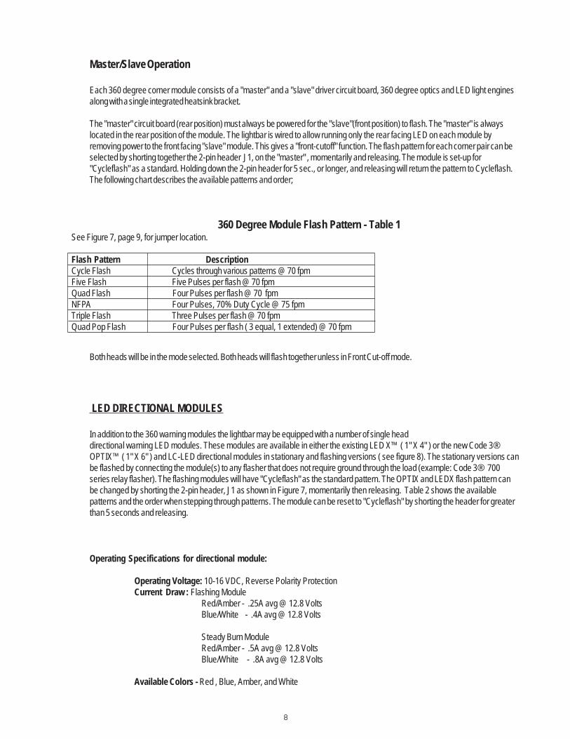
Master/Slave Operation
Each 360 degree corner module consists of a "master" and a "slave" driver circuit board, 360 degree optics and LED light enginesalong with a single integrated heatsink bracket.
The "master" circuit board (rear position) must always be powered for the "slave"(front position) to flash. The "master" is alwayslocated in the rear position of the module. The lightbar is wired to allow running only the rear facing LED on each module byremoving power to the front facing "slave" module. This gives a "front-cutoff" function. The flash pattern for each corner pair can beselected by shorting together the 2-pin header J1, on the "master" , momentarily and releasing. The module is set-up for"Cycleflash" as a standard. Holding down the 2-pin header for 5 sec., or longer, and releasing will return the pattern to Cycleflash.The following chart describes the available patterns and order;
360 Degree Module Flash Pattern - Table 1See Figure 7, page 9, for jumper location.
Flash Pattern DescriptionCycle Flash Cycles through various patterns @ 70 fpmFive Flash Five Pulses per flash @ 70 fpmQuad Flash Four Pulses per flash @ 70 fpmNFPA Four Pulses, 70% Duty Cycle @ 75 fpmTriple Flash Three Pulses per flash @ 70 fpmQuad Pop Flash Four Pulses per flash ( 3 equal, 1 extended) @ 70 fpm
Both heads will be in the mode selected. Both heads will flash together unless in Front Cut-off mode.
LED DIRECTIONAL MODULES
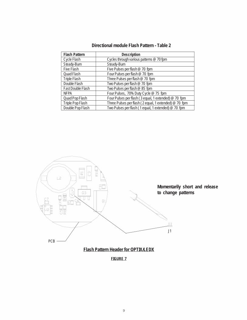
In addition to the 360 warning modules the lightbar may be equipped with a number of single headdirectional warning LED modules. These modules are available in either the existing LED X™ ( 1" X 4" ) or the new Code 3®OPTIX™ ( 1" X 6" ) and LC-LED directional modules in stationary and flashing versions ( see figure 8). The stationary versions canbe flashed by connecting the module(s) to any flasher that does not require ground through the load (example: Code 3® 700series relay flasher). The flashing modules will have "Cycleflash" as the standard pattern. The OPTIX and LEDX flash pattern canbe changed by shorting the 2-pin header, J1 as shown in Figure 7, momentarily then releasing. Table 2 shows the availablepatterns and the order when stepping through patterns. The module can be reset to "Cycleflash" by shorting the header for greaterthan 5 seconds and releasing.
Operating Specifications for directional module:
Operating Voltage: 10-16 VDC, Reverse Polarity ProtectionCurrent Draw : Flashing Module
Red/Amber - .25A avg @ 12.8 VoltsBlue/White - .4A avg @ 12.8 Volts
Steady Burn ModuleRed/Amber - .5A avg @ 12.8 VoltsBlue/White - .8A avg @ 12.8 Volts
Available Colors - Red , Blue, Amber, and White
9
Directional module Flash Pattern - Table 2
Flash Pattern DescriptionCycle Flash Cycles through various patterns @ 70 fpmSteady-Burn Steady-BurnFive Flash Five Pulses per flash @ 70 fpmQuad Flash Four Pulses per flash @ 70 fpmTriple Flash Three Pulses per flash @ 70 fpmDouble Flash Two Pulses per flash @ 70 fpmFast Double Flash Two Pulses per flash @ 85 fpmNFPA Four Pulses, 70% Duty Cycle @ 75 fpmQuad Pop Flash Four Pulses per flash ( 3 equal, 1 extended) @ 70 fpmTriple Pop Flash Three Pulses per flash ( 2 equal, 1 extended) @ 70 fpmDouble Pop Flash Two Pulses per flash ( 1 equal, 1 extended) @ 70 fpm
FIGURE 7
Flash Pattern Header for OPTIX/LEDX
J1
PCB
Momentarily short and releaseto change patterns
10
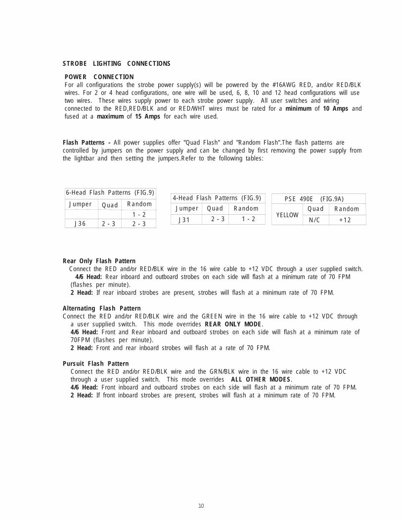
POWER CONNECTIONFor all configurations the strobe power supply(s) will be powered by the #16AWG RED, and/or RED/BLKwires. For 2 or 4 head configurations, one wire will be used, 6, 8, 10 and 12 head configurations will usetwo wires. These wires supply power to each strobe power supply. All user switches and wiringconnected to the RED,RED/BLK and or RED/WHT wires must be rated for a minimum of 10 Amps andfused at a maximum of 15 Amps for each wire used.
STROBE LIGHTING CONNECTIONS
Flash Patterns - All power supplies offer "Quad Flash" and "Random Flash".The flash patterns arecontrolled by jumpers on the power supply and can be changed by first removing the power supply fromthe lightbar and then setting the jumpers.Refer to the following tables:
Rear Only Flash Pattern Connect the RED and/or RED/BLK wire in the 16 wire cable to +12 VDC through a user supplied switch. 4/6 Head: Rear inboard and outboard strobes on each side will flash at a minimum rate of 70 FPM
(flashes per minute).2 Head: If rear inboard strobes are present, strobes will flash at a minimum rate of 70 FPM.
Alternating Flash PatternConnect the RED and/or RED/BLK wire and the GREEN wire in the 16 wire cable to +12 VDC through
a user supplied switch. This mode overrides REAR ONLY MODE.4/6 Head: Front and Rear inboard and outboard strobes on each side will flash at a minimum rate of70FPM (flashes per minute).2 Head: Front and rear inboard strobes will flash at a rate of 70 FPM.
Pursuit Flash PatternConnect the RED and/or RED/BLK wire and the GRN/BLK wire in the 16 wire cable to +12 VDCthrough a user supplied switch. This mode overrides ALL OTHER MODES.4/6 Head: Front inboard and outboard strobes on each side will flash at a minimum rate of 70 FPM.2 Head: If front inboard strobes are present, strobes will flash at a minimum rate of 70 FPM.
6-Head Flash Patterns (FIG.9)
J u m p e r Q u a d RandomJ u m p e r Q u a d Random
J 3 6 J 3 1 2 - 3 1 - 22 - 3 2 - 3
1 - 2
PSE 490E (FIG.9A)
YELLOWQ u a d Random
N / C + 1 2
4-Head Flash Patterns (FIG.9)
11
WA R N I N G !
Lamps are extremely hot! Allow to cool completely before attempting toremove. Gloves and eye protection should be worn when handling halogenlamps as they are pressurized and accidental breakage can result in flyingg lass.
!
Main tenanceLens CleaningUse plain water and a soft cloth, or Code 3,® Inc. lens polish and a very soft paper towel or facial tissue.Because plastic scratches easily, cleaning is recommended only when necessary (about every sixmonths). Do not subject the lenses to car washes that use brushes, as these will scratch the lenses.
Lens RemovalFirst, unscrew the screws on the outside end sections of the lightbar (2 per lens). Carefully, insert ascrewdriver into the inside edge or corner of the lens, and twist the screwdriver to lift the lens. As thelens is being lifted, pay special attention not to stress the black bridge pieces by twisting up on them.
Failure to do so may result in a bridge piece snapping from torsional stress. Remove one outboardsection first, then remove the bridge support bracket. Move the bridge piece slightly to provide enoughgap to remove the center lens(es) efficiently. Finally, remove the remaining outboard section, thus,exposing the lightbar for maintenance.
Replacement of LensesFirst, replace the outboard section back upon the frame. Pay close attention to ensure that the finger tabsinside of the lens catches the aluminum extrusion. Failure to do so may result in water leakage insideof the lightbar. Place either outboard lens on first, then the center section(s), followed by the remaining
12
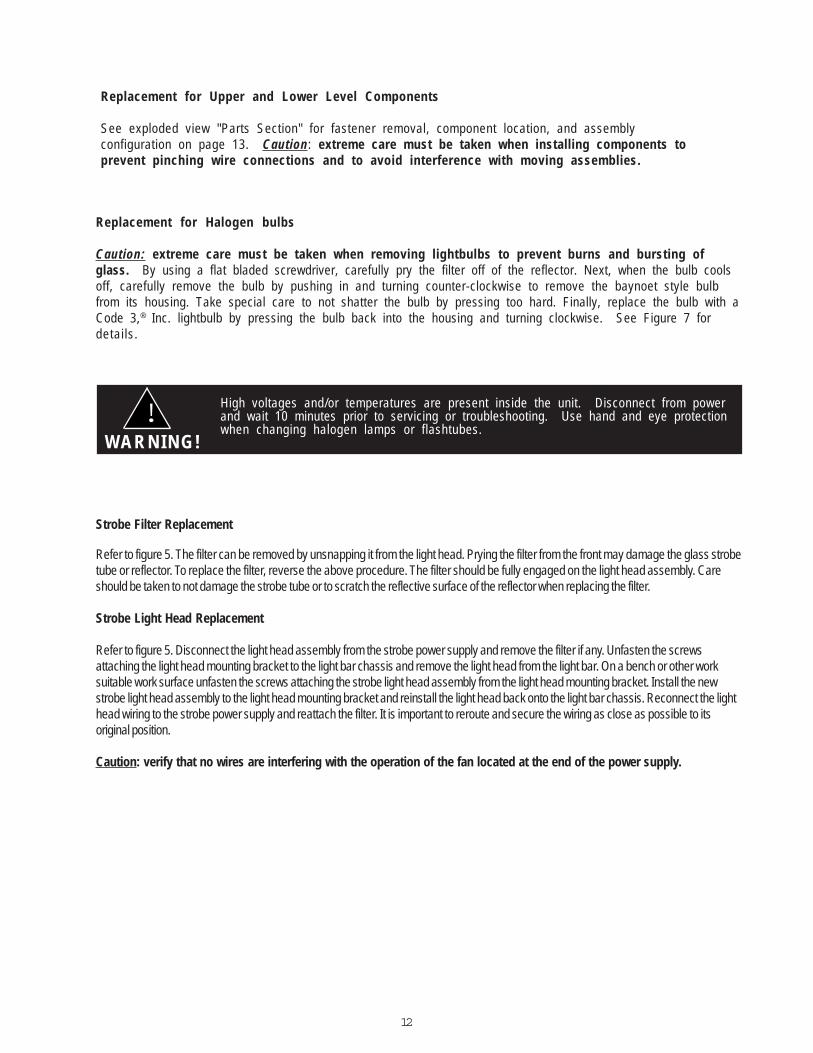
Replacement for Upper and Lower Level Components
See exploded view "Parts Section" for fastener removal, component location, and assemblyconfiguration on page 13. Caution: extreme care must be taken when installing components toprevent pinching wire connections and to avoid interference with moving assemblies.
!WA R N I N G !
High voltages and/or temperatures are present inside the unit. Disconnect from powerand wait 10 minutes prior to servicing or troubleshooting. Use hand and eye protectionwhen changing halogen lamps or flashtubes.
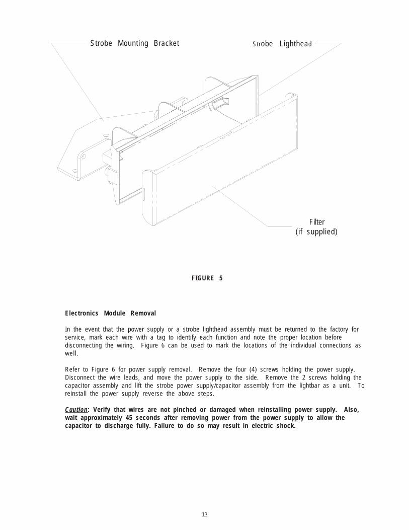
Strobe Filter Replacement
Refer to figure 5. The filter can be removed by unsnapping it from the light head. Prying the filter from the front may damage the glass strobetube or reflector. To replace the filter, reverse the above procedure. The filter should be fully engaged on the light head assembly. Careshould be taken to not damage the strobe tube or to scratch the reflective surface of the reflector when replacing the filter.
Strobe Light Head Replacement
Refer to figure 5. Disconnect the light head assembly from the strobe power supply and remove the filter if any. Unfasten the screwsattaching the light head mounting bracket to the light bar chassis and remove the light head from the light bar. On a bench or other worksuitable work surface unfasten the screws attaching the strobe light head assembly from the light head mounting bracket. Install the newstrobe light head assembly to the light head mounting bracket and reinstall the light head back onto the light bar chassis. Reconnect the lighthead wiring to the strobe power supply and reattach the filter. It is important to reroute and secure the wiring as close as possible to itsoriginal position.
Caution: verify that no wires are interfering with the operation of the fan located at the end of the power supply.
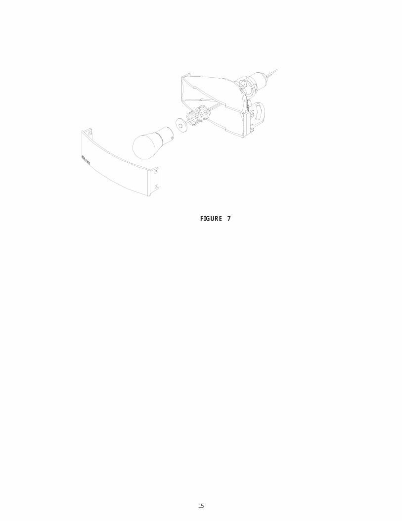
Replacement for Halogen bulbs
Caution: extreme care must be taken when removing lightbulbs to prevent burns and bursting ofglass. By using a flat bladed screwdriver, carefully pry the filter off of the reflector. Next, when the bulb coolsoff, carefully remove the bulb by pushing in and turning counter-clockwise to remove the baynoet style bulbfrom its housing. Take special care to not shatter the bulb by pressing too hard. Finally, replace the bulb with aCode 3,® Inc. lightbulb by pressing the bulb back into the housing and turning clockwise. See Figure 7 fordetai ls.
13
Electronics Module Removal
In the event that the power supply or a strobe lighthead assembly must be returned to the factory forservice, mark each wire with a tag to identify each function and note the proper location beforedisconnecting the wiring. Figure 6 can be used to mark the locations of the individual connections aswel l .
Refer to Figure 6 for power supply removal. Remove the four (4) screws holding the power supply.Disconnect the wire leads, and move the power supply to the side. Remove the 2 screws holding thecapacitor assembly and lift the strobe power supply/capacitor assembly from the lightbar as a unit. Toreinstall the power supply reverse the above steps.
Caution: Verify that wires are not pinched or damaged when reinstalling power supply. Also,wait approximately 45 seconds after removing power from the power supply to allow thecapacitor to discharge fully. Failure to do so may result in electric shock.
Strobe Lighthead
Filter(if supplied)
FIGURE 5
Strobe Mounting Bracket

14
FIGURE 6
4-Head Power Supply
6-Head Power Supply
+ 1 2 V D C (Red)
+ 1 2 V D C (Red)
Ground Wire (Blk)
Ground Wire (Blk)
Control WireHarness(Yel/Blk,Brn/Blk)
Control WireHarness (Yel/Blk,Brn/Blk)
Passenger's Side Front(Org,Blk ,Blk /Wht)Driver's Side Front(Brn,Blk,Blk /Wht)Passenger's Side Rear(Grn,Blk ,Blk /Wht)Driver's Side Rear(Yel ,Blk,Blk/Wht)
Rear Aux. Output(Red,Blk ,B lk /Wht)Rear Output(Grn,Blk ,Blk /Wht)Rear Output(Yel ,Blk,Blk/Wht)
Front Output(Brn,Blk,Blk /Wht)Front Output(Org,Blk ,Blk /Wht)Front Aux. Output(Wht ,B lk ,B lk /Wht)
15
FIGURE 7
16
JAV
ELI
N®
EX
PLO
DE
D
VIE
W
FIG
UR
E
8
Larg
e C
orne
r St
robe
sSe
t in
Dire
ctio
nal
and
Cor
ner
Con
figur
atio
ns(S
5122
9)
Sing
le D
irect
iona
l L
ED(S
5124
3 th
roug
h S5
1248
)
Smal
l C
orne
r St
robe
(S51
230)
Sing
le C
orne
r LE
DM
odul
e (S
5123
1th
roug
h S5
1236
)
50W
Tak
edow
n Li
ghts
(S51
255)
Dua
l D
irect
iona
l LE
DM
odul
e (S
5124
9th
roug
h S5
1252
)
Jave
lin
Inte
rsec
tion
Swee
p Li
ght
(D.S
. S5
1257
)(P
.S.
S512
58)
27 W
Sta
tiona
ryLi
ghts
(S
5125
3)
MR
16 A
lley
Ligh
t(S
5125
6)
Stro
be 4
-Hea
d Po
wer
Supp
ly
Mod
ule
(S51
225)
7
7
45
5
44753
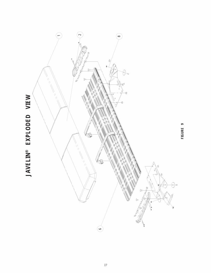
17
FIG
UR
E
9
JAV
ELI
N®
EX
PLO
DE
D
VIE
W
1 82
6

18
Parts/Modules List(Reference numbers identify items shown in Figures on previous pages)Ref No. Description Part No.
Lens ModulesSingle clear outboard section lens module S51217Single red outboard section lens module S51219Single blue outboard section lens module S51218Single amber outboard section lens module S51220
Single clear center section lens module S51221Single red center section lens module S51222Single blue center section lens module S51223Single amber center section lens module S51224
Intersection Light ModulesDS intersection light module upper level S51257PS intersection light module upper level S51258
LED ModulesLED corner lighthead short module red DS S51231LED corner lighthead short module blue DS S51232LED corner lighthead short module amber DS S51233LED corner lighthead short module red PS S51234LED corner lighthead short module blue PS S51235LED corner lighthead short module amber PS S51236LED corner lighthead tall dual module red DS S51237LED corner lighthead tall dual module blue DS S51238LED corner lighthead tall dual module amber DS S51239LED corner lighthead tall dual module red PS S51240LED corner lighthead tall dual module blue PS S51241LED corner lighthead tall dual module amber PS S51242LED single lighthead flashing red S51243LED single lighthead flashing blue S51244LED single lighthead flashing amber S51245LED single lighthead steady red S51246LED single lighthead steady blue S51247LED single lighthead steady amber S51248LED dual lighthead flashing red S51249LED dual lighthead flashing blue S51250LED dual lighthead flashing amber S51251LED dual lighthead flashing red/blue S51252
Stationary Modules27w halogen stationary module S5125328w incandescent stationary module S5125450w halogen stationary module S51255MR16 50w stationary module S51256
2
1
3
4
5
19
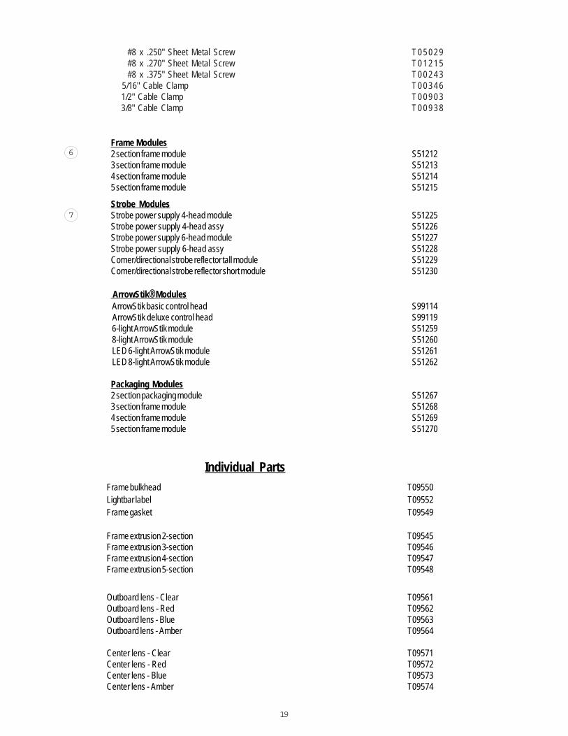
ArrowStik® Modules ArrowStik basic control head S99114 ArrowStik deluxe control head S99119 6-light ArrowStik module S51259 8-light ArrowStik module S51260 LED 6-light ArrowStik module S51261 LED 8-light ArrowStik module S51262
Packaging Modules2 section packaging module S512673 section frame module S512684 section frame module S512695 section frame module S51270
Individual Parts
Strobe ModulesStrobe power supply 4-head module S51225Strobe power supply 4-head assy S51226Strobe power supply 6-head module S51227Strobe power supply 6-head assy S51228Corner/directional strobe reflector tall module S51229Corner/directional strobe reflector short module S51230
Frame Modules2 section frame module S512123 section frame module S512134 section frame module S512145 section frame module S51215
6
7
Frame bulkhead T09550Lightbar label T09552Frame gasket T09549
Frame extrusion 2-section T09545Frame extrusion 3-section T09546Frame extrusion 4-section T09547Frame extrusion 5-section T09548
Outboard lens - Clear T09561Outboard lens - Red T09562Outboard lens - Blue T09563Outboard lens - Amber T09564
Center lens - Clear T09571Center lens - Red T09572Center lens - Blue T09573Center lens - Amber T09574
#8 x .250" Sheet Metal Screw T 0 5 0 2 9 #8 x .270" Sheet Metal Screw T 0 1 2 1 5 #8 x .375" Sheet Metal Screw T 0 0 2 4 3 5/16" Cable Clamp T 0 0 3 4 6 1/2" Cable Clamp T 0 0 9 0 3 3/8" Cable Clamp T 0 0 9 3 8
20
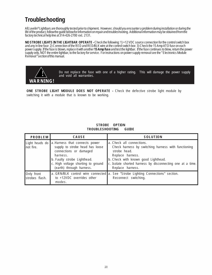
STROBE OPTIONTROUBLESHOOTING GUIDE
P R O B L E M
Light heads donot fire.
Only frontstrobes flash.
C A U S E
a .Harness that connects powersupply to strobe head has looseconnections or damagedharness.
b . Faulty strobe Lighthead.c . High voltage shorting to ground
(earth) through harness.
a . GRN/BLK control wire connectedto +12VDC overrides otherm o d e s .
S O L U T I O N
a . Check all connections.Check harness by switching harness with functioningstrobe head.Replace harness.
b . Check with known good Lighthead.c . Isolate shorted harness by disconnecting one at a time.
Replace harness.
a . See "Strobe Lighting Connections" section.Reconnect switching.
TroubleshootingAll Javelin® Lightbars are thoroughly tested prior to shipment. However, should you encounter a problem during installation or during thelife of the product, follow the guide below for information on repair and troubleshooting. Additional information may be obtained from thefactory technical help line at 314-426-2700 ext. 2131.
NO STROBE LIGHTS IN THE LIGHTBAR OPERATE - Check the following: 1) +12 VDC source connection for the control switch boxand any in line fuse 2) Connection of the RED and RED/BLK wire at the control switch box 3) Check the 15 Amp ATO fuse on eachpower supply. If the fuse is blown, replace it with another 15 Amp fuse and test the lightbar. If the fuse continues to blow, return the powersupply only, NOT the entire lightbar, to the factory for service. For instructions on power supply removal see the " Electronics ModuleRemoval " section of this manual.
Do not replace the fuse with one of a higher rating. This will damage the power supplyand void all warranties.
WA R N I N G !!
ONE STROBE LIGHT MODULE DOES NOT OPERATE - Check the defective strobe light module byswitching it with a module that is known to be working.
21
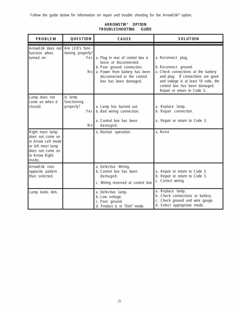
P R O B L E M
ArrowStik does notfunction whenturned on
Lamp does notcome on when itshould.
Right most lampdoes not come onin Arrow Left modeor left most lampdoes not come onin Arrow Rightm o d e .
ArrowStik runsopposite patternthan selected.
Lamp looks dim.
C A U S E
a . Plug in rear of control box isloose or disconnected.
b . Poor ground connectiona . Power from battery has been
disconnected or the controlbox has been damaged.
a . Lamp has burned out.b . Bad wiring connection.
a . Control box has beendamaged .
a . Normal operation
a . Defective Wiring.b . Control box has been
damaged .
c. Wiring reversed at control box
a . Defective lamp.b . Low voltage.c . Poor groundd. Product is in "Dim" mode.
S O L U T I O N
a . Reconnect plug.
b . Reconnect ground.a . Check connections at the battery
and plug. If connections are goodand voltage is at least 10 volts, thecontrol box has been damaged.Repair or return to Code 3.
a . Replace lamp.b . Repair connection.
a . Repair or return to Code 3.
a . N o n e
a . Repair or return to Code 3.b . Repair or return to Code 3.c. Correct wiring
a . Replace lamp.b . Check connections or battery.c . Check ground and wire gauge.d . Select appropriate mode.
Q U E S T I O N
Are LED's func-tioning properly?
Ye s
N o
Is lampfunct ioningproper ly?
Ye s
N o
Follow the guide below for information on repair and trouble shooting for the ArrowStik® option.
ARROWSTIK® OPTIONTROUBLESHOOTING GUIDE
22
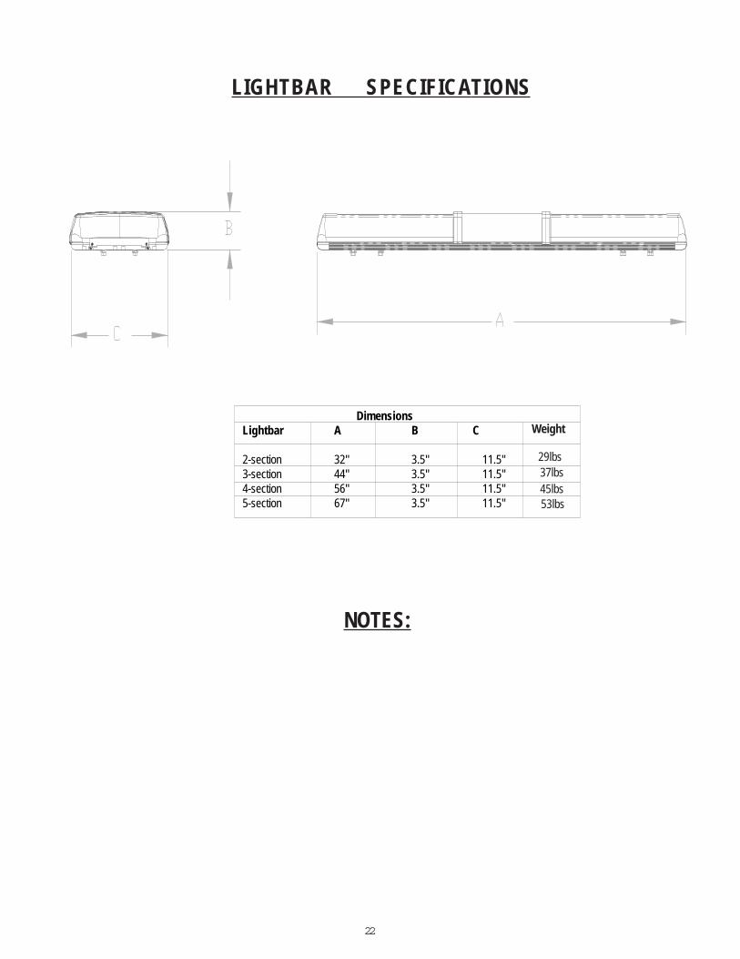
LIGHTBAR SPECIFICATIONS
DimensionsLightbar A B C
2-section 32" 3.5" 11.5"3-section 44" 3.5" 11.5"4-section 56" 3.5" 11.5"5-section 67" 3.5" 11.5"
Weight
37lbs 29lbs
45lbs 53lbs
NOTES:

23
NOTES:
24
Code 3,® Inc. is a registeredtrademark of Code 3, Inc.,
Revision 3, 07/05 - Instruction Book Part No. T09559©2004 Code 3, Inc. Printed in USA
WA R R A N T YCode 3®, Inc.'s emergency devices are tested and found to be operational at the time of manufacture. Provided they
are installed and operated in accordance with manufacturer's recommendations, Code 3®, Inc. guarantees all parts andcomponents except the lamps to a period of 1 year (unless otherwise expressed) from the date of purchase or delivery,whichever is later. Units demonstrated to be defective within the warranty period will be repaired or replaced at the factoryservice center at no cost.
Use of lamp or other electrical load of a wattage higher than installed or recommended by the factory, or use ofinappropriate or inadequate wiring or circuit protection causes this warranty to become void. Failure or destruction of theproduct resulting from abuse or unusual use and/or accidents is not covered by this warranty. Code 3®, Inc. shall in no waybe liable for other damages including consequential, indirect or special damages whether loss is due to negligence or breachof warranty.
CODE 3®, INC. MAKES NO OTHER EXPRESS OR IMPLIED WARRANTY INCLUDING, WITHOUTLIMITATION, WARRANTIES OF FITNESS OR MERCHANTABILITY, WITH RESPECT TO THIS PRODUCT.
PRODUCT RETURNSIf a product must be returned for repair or replacement*, please contact our factory to obtain a Return Goods
Authorization Number (RGA number) before you ship the product to Code 3®, Inc. Write the RGA number clearly onthe package near the mailing label. Be sure you use sufficient packing materials to avoid damage to the product beingreturned while in transit.
*Code 3®, Inc. reserves the right to repair or replace at its discretion. Code 3®, Inc. assumes no responsibility or liability for expenses incurred for the removal and/orreinstallation of products requiring service and/or repair.; nor for the packaging, handling, and shipping: nor for the handling of products return to sender after the service has beenrendered.
Code 3,® Inc.10986 N. Warson Road
St. Louis, Missouri 63114-2029—USAPh. (314) 426-2700 Fax (314) 426-1337
w w w . c o d e 3 p s e . c o ma subsidiary of Public SafetyEquipment, Inc.