Embed Size (px)
Citation preview

I
! 1 ItI i
MAGNETIC BEARINGREACTION WHEEL
FINAL REPORT
JPL CONTRACT NO. 954143
This work was performed for the Jet Propulsion Laboratory,California Institute of Technology sponsored by the NationalAeronautics and Space Administration under Contract NAS7-100.
q_PREPARED BY
A. Sabnis
JL -PEI:L ¥
PHOENIX, ARIZONA
coPY NO
PRINTED IN U.S.A.
FEBRUARY 1976 PUB. NO. 71.0853-0000
https://ntrs.nasa.gov/search.jsp?R=19760020248 2018-06-05T14:47:08+00:00Z

TECHNICAL CONTENT STATEMENT
This report contains information prepared by Sperry Flight Systems under JPL
subcontract. Its content is not necessarily endorsed by the Jet Propulsion
Laboratory, California Institute of Technology, or the National Aeronautics and
Space Administration.
4_
r

ABSTRACT
The results of a program for the development, fabrication and functional test
of an engineering model magnetically suspended reaction wheel are described in
this report. The reaction wheel develops an angular momentum of ±.5 foot-pound-
second and is intended for eventual application in the attitude control of long-
llfe interplanetary and orbiting spacecraft. A description of the wheel design
and its major performance characteristics is presented. Recommendations for flight
prototype development are made.
ii

L
SUMMARY
This report describes the results uf a program for the development of an
engineering model Magnetic Bearing Reaction Wheel (MBRW). The intended applica-
tion for the MBRW is in the attitude control of long life interplanetary and
crbiting spacecraft. The primary advantages sought through the use of magnetic
suspension are long life, high reliability, low induced vibration and precise
control characteristics. The elimination of surface contact enables wear-free,
vacuum-compatible, unlubricated operation. In addition, it was desired to min-
imize wheel weight and particularly power to meet typical outer-planet space-
craft functional requirements.
A photograph of the MBRW and its associated electronics assembly is shown in
Figure i-I and the outline drawing with overall dimensions is shown in Figure
i-2. The design concept evolved in a prior study* was used as the baseline for
the detailed design of the MBRW: the major differences were the addition of a
high-resolution tachometer and the provision of complete redundancy in the elec-
tronics. Two passive-radial, active-axial magnetic bearings were used for the
suspension system. This arrangement also permits the achievement of transverse
angular stability by passive means, and requires active servo control in only
the axial direction. The axial control force is generated by modulating the per-
nmnent magnet fields; a positive integral feedback in the control loop minimizes
power consump=ion _nd sensitivity to electronic component drift.
A large diameter ac induction motor with segmented stators enables efficient
use of the motor rotor mass to provide a significant portion of the rotational
inertia, while permitting full functional redundancy. The MBRW rotor is umbrella-
shaped, and has integrally machined teeth for use in the tachometer system. A
ball-bearing touchdown system provides rotational support when the axial control
system is inoperative, and also prevents physical contact at the magnetic bearing
gaps, the motor gap and the tachometer probe gaps.
Functional tests were conducted on the MBRW, including suspension characteris-
tics, torque characteristics and power measurements. Major MBRW parameters are
listed in Table i-I. Functional testing of the MBRW was successful and the para-
meter comparison confirms the feasibility of the approach for a flight design.
*Final Report: "Design Study for a Magnetically Supported Reaction Wheel,"
JPL Contract No. 953884, Sperry Flight Systems Pub. No. 71-0489-00-00, July 1974.
iii

I 11I
f
Areas of departure from the predicted design values and the requisite design modi-
fications are discussed in the report. The section on conclusions and recommenda-
tions identifies areas which would probably require effort in a subsequent program
for development of flight hardware.
TABLE i-]
MAJOR MBRW PARAMETERS
Parameter Design Requirement Attained Value
Angular Momentum ±.5 ft-lb-sec
Weight*
Output torque (minimum)
Power
• Motor
(a) at .007 ft-lb
torque
(b) at .02 ft-lb
torque
• Bearing (steady-
state)
Calculated Reliability
(10 years)
Tachometer
Size
8.0 pounds
.02 ft-lb
i4.2 watts
12 watts
i
I .5 watt
.98
360 pulses/rev
9 inch diameter
(max imum)
_+.5 ft-lb-sec (at +_700
rpm)
8.9 pounds**
•02 ft-lb
3.62 watts
9.56 watts
•67 watt
.995
520 pulses/rev
8.9 inch diameter
6 inches axial length
*Including estimated weight of flight-type redundant suspenslon electronics
but excluding the weight of the tachometer electronics, as defined in the
Design Requirements.
**The 700 rpm design point was chosen as a lower-power option by JPL be-
cause of the sensitivity to power in anticipated outer-planet missions.
Choice of a 1000 rpm maximum speed would result in a MBRW weight of 8.2
pounds and still meet power requirements. Use of magnesium instead of
aluminum for the housing would lower the MBRW weight further, to 7.5
pounds•
iv

,4
F igt,re [-!
,_I}%Ri_'_lnd Associated Elect-tonics Assei_blv
716 5 30

3.96/
/-
////
/"//
//
i/
MOUNTING
SURFACE1.12
6.13
CHANNEL 1 _ " -'
CONNECTOR
7.80 DIA
I _ ii _ i
/ ,- CHANNEL, iCONNECTOR [
8.87 DIA
MOUNTING PADS
WITH ,250-20 TAPPED HOLES, .37 DEEP,
3 PLACES ON 8.50 DIA716-5-32
Figure i-2
MBRW Outline

Section
1.0
2.0
3.0
TABLE OF CONTENTS
TECHNICAL CONTENT STATEMENT
ABSTRACT
SUMMARY
INTRODUCTION
1.1 Background
1.2 Technical Approach
DESIGN OF THE ENGINEERING MODEL MAGNETIC
BEARING REACTION WHEEL (MBRW)
2.1 System Configuration
2.2 Design Requirements and Objectives
2.3 MBRW Design and Construction
2.4 Optimization and Sizing
2.5 Magnetic Bearings
2.6 Suspension Control System
2.7 Suspension Electronics
2.8 Tachometer
2.9 Monitoring Electronics
2.10 Reliability Analysis
MBRW CALIBRATION AND TEST RESULTS
3.1 Rotor and Suspension System Characteristics
3.2 Control System Performance
3.3 MBRW Torq, rharacterlstics
3.4 Tachometer bystem
Page No.
i
ii
ill
1-1
1-1
1-2
2-1
2-1
2-2
2-2
2-7
2-8
2-10
2-11
2-13
2-14
2-16
3-1
3-I
3-2
3-5
3-8
v

Section
4.0
5.0
Appendices
A
TABLE OF CONTENTS (cont)
CONCLUSIONS AND RECOMMENDATIONS
NEW TECHNOLOGY
ROTOR BALANCING TECHNIQUE
INFLUENCE OF STRUCTURE ON THE SUSPENSION SYSTEM
Page No.
4-I
5-I
A-I
B-I
vl

t
4iv
Figure
No.
i-I
i-2
2-I
2-2
2-3
2-4
2-5
2-6
2-7
2-8
2-9
2-10
2-11
2-12
2-13
2-14
2-15a
2-1 5b
2-16
2-17
3-1
3-2
3-3
LIST OF ILLUSTRATIONS
Follows
Page No.
MBRW and Associated Electronics Assembly Ill
MBRW Outline ill
MBRW System Configuration 2-I
MBRW Design Layout 2-3
Rotor Assembly 2-4
Lower Housing Assembly 2-4
MBRW Weight as a Function of Speed and Size 2-8
One-Loop Bearing System 2-9
Linear System Model of Axial Control System 2-10
Root Locus, Axial Control System 2-11
Suspension Electronics - Block Diagram (One of two Channels) 2-11
Rotor Sensing with Single Position Sensor 2-12
Rotor Sensing with Series Connected Position Sensors 2-12
Power Bridge Voltage Deadband 2-13
Power Bridge Characteristic after Elimination of Deadband 2-13
by Biasing
Tachometer Probe Arrangement (One of Two Channels) 2-13
Tachometer Electronics Block Diagram (One of Two Channels) 2-14
One-Shot Operatien 2-14
Monitoring Electronics Block Diagram 2-14
MBRW Reliability Model 2-16
Compensated Open-Loop Gain and Phase Response Showing 3-3
Effect of Web Compliance
Compensated Open-Loop Gain and Phase Response without 3-3
Web Compliance
Coil Current and Rotor Position at Lift Off (Rotor 3-3
Traveling away from Position Senscrs)
vii

!
I
LIST OF ILLUSTRATIONS (cont)
Figure
No.
3-'4
3-5
3-6
3-7
3-8
3-9
A-I
A-2
B-I
Coil Current and Rotor Position at Lift Off (Rotor
Traveling Toward Position Sensors)
Axial Position Step Response (10 Hz Square Wave Excitation)
MBRW Reaction Torque, 1.34 oz-in. Minimum
MBRW Reaction Torque, 3.84 oz-in. Minimum
MBRW Drag Torque
Tachometer Output Pulses (520 Pulses/Rev) at a Rotor
Speed of 700 rpm
Sensing Rotor Motions Due to Unbalance
Balancing Phasor Diagrams
Structural Model to Illustrate Effect of Housing
Flexibility
Pole Location due to Housing Flexibility
Effect of Flexibility on Open-Loop Response
Follows
Page No.
3-3
3-4
3-5
3-5
3-5
3-8
A-I
A-I
B-I
viii

i
I
l
SECTION 1.0
INTRODUCTION

\ I•
SECTION 1.0
INTRODUCTION
1.1 BACKGROUND
The use of Reaction Wheel Assemblies (RWAs) is a demonstrated technique for
precise attitude control of spacecraft. In a typical system, three orthogonally
mounted RWAs are employed, each developing bidirectional control torques about a
spacecraft axis in response to attitude sensor signals.
For anticipated future outer-planet spacecraft applications, RWA operating
life is of prime interest. Ball bearing supported wheels have achieved lifetimes
in the neighborhood of 5 years, but their continuous use for 10 year missions is
open to question. This is primarily because of the necessity of assuring the
presence of a lubricant in the ball contact area over the required time, and of
providing a load-carrying film (boundary lubrication) in the region of zero spin
speed.
The obvious solution to the problem is to avoid metal-to-metal contact in
the suspension elements, and to eliminate the need for lubrication. Magnetic
suspension constitutes such a contactless support system and forms the basis of
the RWA development described in this report.
The feasibility of using magnetic bearings in a reaction wheel for inter-
planetary and orbiting spacecraft was examined in a prior design study (JPL Con-
tract No. 953884). It was concluded that a Magnetic Bearing Reaction Wheel
(MBRW) would be competitive with ball bearing designs in terms of size, weight,
power and cost.
Following the design study, a program for the detailed design, fabrication and
functional testing of an engineering model MBRW was initiated (JPL Contract No.
954143) in order to confirm the conclusions of the study. The primary differences
from the requirements of the study were the inclusion of complete redundancy in the
system and the incorporation of a hlgh-resolution tachometer. The tachometer is
intended to be used for precise control of MBRW rotational speed in a speed control
loop. This report describes the results of the development effort and is sub-
mitted in partial fulfillment of JPL Contract No. 954143.
;-I

1.2 TECHNICALAPPROACH
The fundamental objective of the program was considered to be the develop-
ment and functional evaluation of an engineering model Magnetic Bearing Reaction
Wheel (MBRW). The use of magnetic suspension enables the reaction wheel to pos-
sess the characteristics of long llfe and high reliability, low power consumption
and precise control characteristics.
The design of the engineering model MBRW was approached as being a flight
design; however, existing hardware and techniques were used in the interest of
economics and schedule, and as a high-confidence approach to achieving the program
goal.
Thus, the one-loop bearing system concept previously developed at Sperry
was used for the magnetic suspension; similarly, an existing 7 inch diameter
segmented ac induction motor was used in the design. The one-loop bearing de-
sign was extrapolated from the design tested in the Sperry one-loop model.
The design considered as a baseline was that evolved in the design study,
JPL Contract No. 953884, with the addition of a high-resolution tachometer. Re-
sults from on-going magnetic suspension development work at Sperry were also in-
corporated into the RWA design.
Design point selection was based on weight optimization, subject to the motor
power constraint. The design incorporated complete redundancy of all systems
(suspension, tachometer and motor) in order to eliminate all single-point failures.
The remainder of this report is organized as follows: Section 2.0 presents
a detailed description of the MBRW design, Section 3.0 contains the results of
MBRW testing, and the conclusions and recommendations are outlined in Section 4.0.
The instructions for installation and operation of the MBRW are contained
in a separate publication, "Operation Manual: Magnetic Bearing Reaction Wheel,"
Sperry Flight Systems Pub. No. 71-0847-00-00.
I-2

7
SECTION 2.0
DESIGN OF THE ENGINEERING MODEL MAGNETIC BEARING REACTION WHEEL

......_1_-_ ¸....... ,_,_ .......... _ •
I
i ! i
SECTION 2.0
DESIGN OF THE ENGINEERING MODEL MAGNETIC BEARING REACTION WHEEL
2.1 SYSTEM CONFIGURATION
A block diagram of the MBRW system is shown in Figure 2-I.
sists of two separate subassemblies:
• Magnetic Bearing Reaction Wheel (MBRW)
• MBRW Electronics Assembly
The system con-
The MBRW consists of the rotor, segmented ac induction motors, magnetic
bearings, touchdown bearings, axial position sensor probes and the tachometer, all
in a sealed housing. The MBRW is, however, designed to be vented to the space
vacuum environment in actual spacecraft operation. The required electronics for
the suspension system, the tachometer system and for monitoring are mounted in the
Electronics Assembly, except for the position sensor drive electronics, which are
mounted on two boards on the underside of the MBRW. The Electronics Assembly is
in breadboard form and is designed to be rack-mounted.
Two separate, identical electronics channels are provided for both the sus-
pension and the tachometer. Redundancy of the spin motor function is possible
because a segmented motor construction is used. Thus, redundancy requires the
use of separate motor stators but not separate rotors since the rotor is a passive
electromagnetic element. The motor leads are brought out to the Electronics As-
sembly. The present design thus permits open-loop sine-wave or square-wave motor
drive, and allows for future incorporation of a spin motor control system.
The monitoring electronics is non-redundant and provides indications of sus-
pension and wheel speed. An overspeed light turns on at 750 rpm, nominal maximum
speed being 700 rpm. Two separate cables provide identical position, tachometer,
motor and control coil interconnections between the MBRW and the Electronics As-
sembly. Separate channel select switches enable choice of either suspension, tach-
ometer or motor channel; a master switch disconnects all power from the entire
system. The MBRW system operates off +28 volts, _15 volts, and +5 volts laboratory
power supplies; the motor is driven by a 0 to 28 volt, 2 phase, 280 Hz supply.
2-I

(
o
¢o
_.-I
O0_IG//V_,,._
_OORQVALrry

2.2 DESIGN REQUIREMENTS AND OBJECTIVES
The important design requirements and goals for the MBRW are listed in Table
2-I. The table also shows the values attained in the actual design, and the
method by which these values were verified. Discussion of the attained values in
relation to the requirements and goals is contained in the appropriate sections
describing the design and/or the test results. References to these sections are
given in the table.
2.3 MBRW DESIGN AND CONSTRUCTION
Minimization of the weight and size of the MBRW was a major consideration
for the design. Other constraints which also had direct effects were the require-
ment for no single point failures, reduction of peak torquing power, and the use
of existing spin motor and magnetic bearing designs. The final design layout is
shown in Figure 2-2.
The MBRW design layout can be divided into two major assemblies - the rotor
assembly and the housing assembly.
a. Rotor Assembly
An "umbrella" rotor configuration was selected because of the need for a
high axial stiffness between magnetic bearing rotors and stators, and the com-
pactness gained by placing the magnetic bearing rotors outboard of the stators.
The rotor assembly is shown in Figure 2-3. The achievement of positive angular
stiffness dictates a minimum axial separation between the two radial-passive
bearings. Since the stators extend further from the gaps than the rotors, overall
=xial length is minimized by placing the stators inboard. The umbrella design also
provides better control of rotor, bearing and shaft geometry and permits easy dis-
assembly of the rotor from the housing.
The spin motor stator segments are placed midway between bearings to pre-
vent possible angular motions of the rotor due to any radial unbilance force of the
motor. This placement of the motor and rotor rim allows use of a conical web which
provides a high hub-to-rim stiffness. Access holes through the rotor web at four
places enable tachometer probe adjustments to be made without removing the rotor
assembly.
2-2

: !' I
i J
TABLE 2-I
DESIGN REQUIREMENTS, GOALS AND ATTAINED VALUES
Design Design
Requirement Goal Value Attained Verified By Referencei Characteristic
IiAngular Momentum
Weight
Size (maximum dimension)
+
! Tachometer Output
t
Output Torque and
Power
Bearing Power
Liftoff
Operating
Capacity in Ig
Axial Damping
Coefficient
Axial Step Response
Resonant Frequencies
Reliability (10 years)
Balance
Static
Dynamic
External Field at
I meter*
DC
Variable
Environment*
Shock and Vibration
tLaunch and Operating)
Temperature
Pressure
_.5 ft-lb-sec
8.0 pounds
360 pulses/rev,
Direction of rota-
tion signal
(a) .007 ft-lb,
4.2 watts
(b) .02 ft-lb,
12 watts
15 watts maximum
(< 5 msec)
.5 watt
Operation in any
attitude
.6
6 msec
Above maximum speed
and _ 20 Hz
.98
.05 oz-in
.5 oz-in 2
Per JPL Snecifica-
tton MJS77-3-240
-20 ° to +75'C
+760 tort to 10 -14
torrt
9 inches
1200 pulses/rev
.25 watt
.005 oz-ln
2•05 oz-in
l0 nT {
4 nT
_.5 ft-lb-sec
8.9 pounds
8.9 inches
520 pulses/rev,
Direction of rota-
tion signal provided
(a) .007 ft-lb, j
3.62 watts
(b) .02 ft-lb,
9.6 wattsr
39.2 watts maximum
.67 watt
Operation with spin axis
vertical and within 20 °
of vertical
7 {
4 msec _
9 Hz (zero speed
angular)
29 Hz (radial)
.995
•0035 oz-in
.019 oz-ln 2 )'
, MBRW desi_ned for launch
J survlwlbillty and opera-
t tion without degradation
MBRW designed for c_per-
atton over temperature
and pressure range
[
Measurement
Measurement
Measurement
Measurement
Section 2.4
Section 2.8
and 3.4
Measurement Section 3.3
Measurement Section 3.2
Observation Section 3.1
Measurement Section 3.2
Measurement Section J.1
Analysis
Measurement
Not measured
Analysts
Section 2.10
Section 3.1
and
Appendix A
Analysis
..........................
*Meaqurement of the external maRnettc field characterl_tlcs and environmental perf,*rmance tests were outride thv q,.+p,. _
th_ pr_,Kra_.
ORIGINALPAGE,iSOF POOR
2-3
LI,

i 4
=
0
c,a
=

t" i r_,ll rt ' 2-- }

Two machined parts form the rotor, the rim/web and shaft. They are ther-
mally interference fitted together and bolted, and the motor cage is in turn ther-
mally fit into the rim. The shaft design is such that all other parts of the rotor
assembly can be assembled on the shaft from one end. The lower magnetic bearing
rotor mounts on the shaft through a disk support; use of this support prevents
direct clamping Oil the relatively soft magnetic bearing rotor, and also provides
sensing surfaces for axial and radial position sensors. The radial sensors are
mounted only for the purpose of rotor balancing, and are removed after balancing
is complete.
b. Housing Assembly
The main structural component of the MBRW is the lower housing. It pro-
vides mounting for motor and tachometer components, forms part of the vacuum en-
closure (required for performance testing in vacuum) and has mounting provisions
(3 pads) at its outer diameter. The lower housing is a single part consisting of
a conical web, with two concentric inner cylinders joined by four ribs. The inner
cylinder provides mounting for the magnetic bearing stators and the lower touch-
down bearings, and the outer cylinder provides mounting for the motor stator seg-
ments and tachometer probes. The motor stator segments are positioned axially by
two shoulders on the outer cylinder of the lower housing, and are held radially by
clamps which also serve as supports for the tachometer probes. This arrangement
is best seen in Figure 2-4.
The tachometer probe mounting arrangement allows radial and tangential
adjustment. The radial adjustment is required to set the nominal probe to tooth
distance and the tangential adjustment is necessary to adjust the phase of one
probe of the tachometer with respect to the other.
The upper housing partially encloses the unit and holds the upper touch-
down bearings. An assembly machining operation of the upper and lower housing parts
aligns the upper and lower touchdown bearings to the spin axis. Circumferential
ribs in the upper housing are used to prevent local buckling of the shell under
atmospheric pressure.
The lower cover completes the enclosure of the MBRW. It contains a port
which is used for evacuation and is sealed by a plug. O-rlng seals are used be-
tween all parts which comprise the MBRW enclosure.
2-4

716 5 31
i"i =riLl-t+ ,._

The semicircular electronics boards are mounted on the lower housing.
Each one contains the electronics for three proximity sensors, motor wiring con-
nections and a connector. Separate headers are provided for the wiring of each
channel, and the signal and power wiring for each channel has its own header for
a total of four hermetc headers in the lower housing. All motor lead wires are
brought through the headers to the boards where connections can be made to suit
the drive scheme and voltage.
c. Spin Motor
The spin motor used in the MBRW is a two-phase ac induction motor. It
consists of a single motor rotor (cage) and a redunda_t, segmented stator. Each
motor channel consists of two diametrically opposed stator segments, each span-
ning 40 degrees of arc. The full stator circumference is equivalent to 32 poles.
Each phase on a stator segment consists of two separate windings in order that the
motor may be either bifilar-connected and driven squarewave or driven sine-wave
(with series or parallel connection). The windings from the two segments can further
be connected in either series or parallel. Operation in the various connections
implies changing the drive voltage for a fixed-motor torque; the torque/power ratio
is unchanged.
The motor cage consists of slotted laminations, axially stacked. Copper
bars are inserted in the slots and are soldered to the copper end rings. The motor
is designed to operate at a nominal radial gap of .024 inch. This relatively large
gap, and the use of the diametrically opposed segments enables the achievement of
low radial unbalance stiffness in the motor.
d. Touchdown Bearing System
A touchdown bearing system is provided to support the rotor, spinning or
non-spinning, whenever the axial control system for the magnetic bearings is not
operating. Duplex pairs of angular contact ball bearings are mounted in each hous-
ing half, outboard of the rotor. Nuts on the lower shaft provide shoulders which
contact the inner races of the lower bearing pair and thereby limit axial motion
in both directions. Shims between the shaft and the shaft end-nut allow the adjust-
ment of the total shaft excursion. Shims between the lower bearing pair and the
bearing support shoulder are used to center the bearings between the shoulders on
the shaft assembly. A third shim adjustment is provided between the lower magnetic
bearing stator and its supporting shoulder in the central tube of the lower housing.
2-5

This shim determines the size of the axial gaps between the magnetic bearing rotors
and stators. No shoulders are used on the upper shaft so that deflection of the
upper housing does not affect the touchdownsystem; this also simplifies assembly
and adjustment of the touchdownbearing system.
The radial and axial gaps between the shaft and the touchdownbearingpairs are sized so that no contact occurs between any rotating and stationary parts
whenthe magnetic suspension system is operating. Since the radial gaps determine
both radial and angular travel, the span between the touchdownbearing pairs be-comesimportant in limiting the angular travel.
The radial touchdowngaps are .010 inch; these touchdowngaps are the
difference between the nominal tachometer gaps and the minimumworst case gaps.
The axial touchdowngaps are set at ±.005 inch. These gaps are large enough sothat when the rotor is at its equilibrium position in Ig with spin axis vertical,
no contact occurs due to the offset of the rotor from its centered position.
Larger axial touchdowngaps would necessitate increased currents and power atlift-off.
The touchdownbearings have radial and axial load capacities sufficient
to prevent damagewhich would compromisetheir function. Since their function is
quite different from spin bearings in a ball bearing reaction wheel (which is to
spin continuously after a launch environmental exposure) different sizing criteria
apply, i.e., higher static load levels can be tolerated without affecting perfor-
mance. On the basis of an analysis of the environmental loadings, the MBRWtouch-
downbearings would be loaded to 145 percent of their thrust capacity and 50 per-
cent of their radial capacity.
e. Materials
The material selected for the rotor web, rim and shaft is 6AL-4V titanium,
based primarily on its thermal expqnsion coefficient being very nearly equal to
that of the electrical iron of motor cage and magnetic bearing rotors. In addition,
it is a stable material with high specific strength (strength-to-density ratio).
The lower magnetic bearing rotor support is also titanium. The housing parts and
cover are madeof 6061aluminum, but can be changed to a magnesiumalloy in future
units for weight reduction.
2-6

L
2.4 OPTIMIZATION AND SIZING
The objective of this optimization is to minimize the unit weight and meet
the performance specifications within the constraints listed below. The design
of Figure 2-2, evolved in the study, was used as a baseline, with the following
constraints:
• Use of existing one-loop magnetic bearing design
• Use of existing segmented-stator ac induction motor design
with redundant stator segments
The specifications which have a direct effect on the optimization are:
• Momentum: ±.5 ft-lb-sec
• Output torque I (a) .007 ft-lb, 4.2 watts
• Maximum input motor power _ (b) .02 ft-lb, 12 watts
A computer program was used to calculate weights as a function of size
(motor cage radius) and speed. Since the optimization result is not affected by
component weights which are fixed, (e.g., electronics) these weights were not in-
cluded in the weight calculation. The variable weights which are accounted for
are those of the rotor assembly, the structure and enclosure. For reference, some
computer runs were made in whic_l the motor stator and cage were also considered
variable within torque and power requirements. For these runs a 4 ounce-inch
(.021 ft-lb) torque and 8 watt power were used since they a e the nominal charac-
teristics of the existing motor design.
The results of the optimization are shown in Figure 2-5. The constant weights
have been included in these curves so that they show realistic MBRW values. These
curves show that the size (3.5 inch radius) dictated _y the use of the existing
motor design is very nearly an optimum if operated at 700 rpm, and the use of
this motor is not a severe restriction. Since this design point, 700 rpm, 3.5 inch
radius, uses 8 watts and the specifications allow 12 watts, an extrapolation was
made to use the full 12 watts and lighten the MBRW design. It was found that at
12 watts the speed is 1000 rpm and the unit weight decreases by .75 pound, indi-
cating weight and power trade-off at about .2 pound per watt in this region. Tl_e
final design point chosen was 700 rpm and 3.5 inch radius, that is, the heavier
and lower power design; this choice was made because of the sensitivity to power in
interplanetary applications. The final weight of the MBRW was 8.9 pounds (in-
cluding estimated weight of flight-type redundant bearing electronics, but not in-
cluding tachometer electronics) and a breakdown of this weight by component is
shown in Table 2-2.
2-7

! 1
TABLE2-2
MBRWCOMPONENTWEIGHTSUMMARY
Component
MBRWTotal
Rotor Assembly
Shaft
Rim-Web-Hub
Magnetic Bearing Rotors (2)
Motor CageMiscellaneous
Magnetic Bearing Stator Assembly(2)
Iron Parts
Coil
Magnet
Spacer
Housing Assembly
Lower Housing
Dpper Housing
Motor Stator (2)
Cover
Tachometer Probe Supports
Touchdown Bearing Support
Tachometer Probes and
Miscellaneous
Electronics Assembly (2)
Component
Weight
• O9
1.74
.11
1.19
.07
.40
.11
.t2
.04
1.26
.75
1.36
.21
.13
.11
.18
Subassembly
Weight
3.2
1.34
4.0
.4
Assembly
Weight
8.9 ibs
2.5 MAGNETIC BEARINGS
The rationale for the selection of adc magnetic, passive-radial, active-
axial bearing system and the one-loop configuration was detailed in the design
study Final Report, JPL Contract No. 953884. In such a system, the achieve-
ment of positive angular stiffness dictates the use of two radial-passlve bear-
ings with adequate axial spacing between them. The stabilizing torque of the
bearing pair due to radial forces is thus made to exceed the destabilizing torque
due to the axial unbalance forces.
2-8

! •
20.0
160
=,12.0
I--.r
_ 8.00p-
i1:J,n
4.0
MOTOR - _2.5OUTER
CAGE
RADIUS l 3.0(INCHES) 3.5
40412
Figure 2-5MBRW Weight as a Function of Speed and Size
200 400 600 800 1000 1200 1400 1600
SPEED (RPM)716522

' I
The one-loop bearing system consists of a rotor and stator assembly at each
end of the rotor shaft, as shown in Figure 2-6. The dc bias flux is provided by
an axially magnetized ring magnet which is in series in the magnetic flux path.
The control coil, which modulates the bias flux, is placed within the magnetic
flux loop. A rlng-groove geometry on the rotor and stator pole-pieces at the
two air gaps is used to increase the radial stiffness.
The performance requirements for the MBRW primarily determine minimum radial
and angular stiffnesses for the suspension system. The constraints are considered
separately below. The mathematical constraint relationships were shown in the
Design Study Report. Only numerical values are shown below.
a. Radial Capacity in a Ig Environment
The constraint on stiffness arises because of the requirement that the
MBRW be capable of suspended operation at any speed, in any attitude, in a Ig
environment and when subjected to a cross-axis rate of 35 milliradians per second.
where
Krl _ 35.7 Wr
b,
Krl = required radial stiffness per bearing (ib/in.)
W = total rotor weight (ibs)r
Radial Resonance Frequency > 20 Hz
where
C,
Kr2 _ 20.5 Wr
Kr2 = required radial stiffness per bearing (ib/in.)
Angular Resonance Frequency > 20 Hz
where
Kr3 _ 80.2 Wr
Kr3 = required radial stiffness per bearing (ib/in.)
The abov_ constraint assumes that the radial and angular stiffness are
such that
I _2% " r
2-9

BIF"_"_'*"_ ........... T .................... T'_ .....
|: i
RING MAGNET
SOFT IRON ,_k_ _\ _ \_
POLE PIECES
CONTROL COIL
SOFT IRON ROTOR
POLE PIECE
Figure 2-6
One-Loop Bearing System

where
K is the angular stiffness (in.-ib/radian)
K is the radial stiffness per bearing (ib/In.)r
and _ is the axial separation between the two bearings, in inches.
d. Other Constraints
The cross-axis rate constraint dictates a radial stiffness of the order
of only 10 ib/in.; the preliminary design indicated that the nlaximum operating
speed would be < 1200 rpm (20 Hz); hence no resonant conditions would be encount-
ered in the nominal operating speed range.
The dominant constraint is seen to be that due to the angular resouance
frequency. For a nominal rotor weight of 3 pounds, this indicates a required
radial stiffness of K = 240 lbs/in, per bearing.r
2.6 SUSPENSION CONTROL SYSTEM
The linear model of the magnetic suspension system used for preliminary de-
sign is shown in Figure 2-7. The suspension system is open-loop unstable (non-
minimum phase) because of the negative static stiffness of the magnetics. The
axial system is made stable by feedback control of the current through the con-
trol coils, based on a sensing of the axial displacement by the position sensor.
The simple linear system model shown departs from the actual system because:
• Structural compliance is not considered. Compliance in the
rotor, stator or in the mounting modifies the system model,
as typified by the analysis in Appendix B.
• In a one-loop bearing system, the control fo-ce/control current
gain varies significantly with axial position because of the
variation of gap flux density.
• Touchdown stops, power supply voltage and cross-over distor-
tion in the amplifier are non-linearities in the actual system.
Several control schemes are possible. The concepts of two schemes were des-
cribed in the Final Report, JPL Contract No. 953884. The scheme implemented in
the MBRW is a lead-lag compensation with mlnor-loop integrator. The lead-la_
2-I0

t
Fext
F c
! Ko tUNBALANCE
STIFFNESS
ms2
CONTROL POWER FEEDBACK AXIALCOIL AMPLIFIER COMPENSATION POSITION
SENSOR
INTEGRATOR 7_ s ;B
Figure 2-7
Linear System Model of Axial Control System

compensation may be thought of as posltlon-rate feedback, and governs the fast
axial dynamics. The addition of the relatively slow integrator enables zero-
current operation under steady axial external loads e.g., in Ig when the MBRW is
being operated with spin axis vertical. The static axial stiffness with the in-
tegrator is thus negative, the rotor being so positioned that the external force
is exactly balanced by the unbalance force of the magnetics. The use of the in-
tegrator also maintains long-term zero-current operation regardless of drift in
the electronics or the position sensor.
The root locus for the control system is shown in Figure 2_8. Preliminary
design numbers used for the analysis are shown in the figure. It can be seen
that the dominant pole is due to the integrator. Of the 3 other poles, at suit-
able values of loop gain, either the complex pair or the real pole can be made
dominant by suitable placement of the lead and lag frequencies. It can be seen
that for the root locus shown K/K = 1.4 will ensure that the damping coefficientU
.6; the dominant real pole is in the region of -400 radians/sec, which will en-
sure a rise time _ 6 msec. The dominant integrator pole is _ 75 radians/sec.
2.7 SUSPENSION ELECTRONICS
The function of the suspension electronics is to provide controlled coil
currents, thus generating axial forces to llft-off and maintain levitation of
the rotor. The main components, as shown in Figure 2-9, are the axial position
probe and its driver, compensation network, power bridge, and an integrator. The
primary design requirements are maximum reliability, axial stability of the rotor,
and minimum power. Complete electronics redundancy is also required to prevent
a single point failure; hence, there are two separate suspension electronics
channels with their corresponding position sensors. Selecting suspension chan-
nels is accomplished at the front panel of the MBRW Electronics Assembly.
a. Position Sensors
The axial position of the rotor is measured by an eddy-circuit position
sensor. The sensing element is a small diameter coll of wire that is excited bv
a high frequency (2 MHz) ac source. The radiated field of the coil sets up eddy-
currents in the sensed surface. Variations of the probe-to-surface _ap cause a
varlation of the probe impedance which changes the ac signal amplitude. This
signal is then filtered to provide adc voltage proportional to displacement
(typically 250 volts/Inch).
2-11

jc,;3OOO
-4O0O
\
_ = 700 RAD/SEC
K i- 40 RAD/SEC
T
1
_1 = 625 RAD/SEC
1-- = 3000 RAD/SECT 2
1-- = 3200 RAD/SECT c
\
-35OO -3000 -2500 -2000 -1500
RAD/SEC
\\
\\ ,J
-- _,c
-1000 -_
Figure 2-8
Root Locus, Axial Control System
/\\
i25OO
!
2O0O
RAD/SEC
5OO
716 5 29

i • L
/
_z
| 'r'-'-----T--
_-- --l---p ...... --_
I__ I
I
[2'
i
,,n
,-..t
0
•M ,'-I
I
m
0
°_me"

The rotor displacement (z) was initially designed to be measured by a
single eddy-current probe positioned .9 inches from the rotor spin axis as shown
in Figure 2-10. However, the single position measurement allowed the angular com-
ponent, + _ z, of rotor movement to be coupled into the axial measuring system,
thereby creating an instability in the suspension electronics. This problem was
corrected by the addition of another probe at the same radius 180 degrees away, as
shown in Figure 2-11. The angular component _ z due to 8 is now removed (PI measures
a - _ z and P2 a + _ z) leaving only the axial component. Series connection of the
probes simplified the electronics by eliminating the need for an extra probe driver
and output summation circuitry; however, exact cancellation of the angular com-
ponent was not possible since the gains of the series-connected probes could not be
individually adjusted. The ultimate solution for this problem is to use an annu-
lar ring probe which averages the probe to rotor gap thereby eliminating angular
variations. Initial development tests on such a probe at Sperry have confirmed
the feasibility of the approach.
b. Compensation
Compensation consists of a single lead/lag network (Figure 2-9). The
gains K I and K 2 and the phase lead are adjusted such that the phase curve is above
-180 degrees (phase margin) at zero dB gain crossover. This keeps the gain below
zero dB when the phase curve is below -180 degrees (gain margin). Adequate gain
and phase margin (> 5 dB, > I0°) ensures axial stability. The lag is adjusted to
prevent structural resonances from affecting stability of the axial system by
attenuating the high frequency gain.
The integrator is used, with positive feedback, to minimize steady-state
power consumption under steady external loads, and to eliminate the effects of
electronic component and position sensor drift over time and temperature. Steady-
state coil currents are integrated and added to the compensated position signal.
The rotor is thus axially repositioned to a point at which the rotor is at a
force equilibrium, with the permanent magnet forces exactly balancing the steady
external axial forces. At this point no coil current is required.
c. Power Amplifier
The power amplifier consists of a linear power bridge which contro|s
current in either direction (with power amplifiers I and 2, Figure 2-9) through
the parallel coils in response to the compensated signal from the position sensor.
2-12

Z
ROTORANGULAR
MOVEMENT
ROTOR
q.
12OUTPUT =
Figure 2-10
Rotor Sensing with Single Position Sensor
Z+_Z
71657
Z
ROTOR
ANGULAR _ I
MOVEMENT/I
OTOR
__Z__._.._ _ Y
PROBEDRIVER
_ OUTPUT _ Z
Figure 2-11
Rotor Sensing with Series Connected Position Sensors

s r
An undesirable characteristic of power bridge circuits is crossover dis-
toctlon. Before either power amplifier will fully conduct, about +1.2 volts (two)
transistor drops) must be present at point c in Figure 2-9. This creates a deadband of
2.4 volts about the coil current axis as shown in Figure 2-.12. The coil current to
voltage gain is lower in this region causing limlt-cycle oscillations. Adding a dc
bias voltage of +2.4 volts at power amplifier I removes the deadband by biasing both _
the power amplifiers Just to the point of conduction as shown in Figure 2-13. Ade-
quate gain for axial stability is now available for all values of input voltage.
The biasing entails a standby power of .25 watt.
Both channels of control electronics are mounted on circuit board cards
which are located in the Electronics Assembly chassis. The power bridges are
mounted on the chassis for heat sinking. The position probes are internally mounted
in the MBRW. The high frequency ac drivers for the probes are mounted on metal
cards on the underside of the MBRW. The gain of the position sensor is dependent on
the cable length between the probe and its driver; the driver location on the under-
side of the MBRW keeps this cable length short which allows more gain and bias volt-
age variation with gap.
2.8 TACHOMETER
Design requirements for tbe tachometer were a minimum of 360 pulses per revolu-
tion and a direction of rotation indication. Employing two specially fabricated
eddy-current probes to sense 130 teeth, machined on the inside of the umbrella rotor,
(see Figure 2-14), the tachometer provides 520 pulses per revolution for speed in-
dication of rotation output. Speed insensitivity of the eddy-current probes allows
accurate indication of rotor speed and direction of rotation through 0 rpm. The
number of teeth (130) were chosen on the basis of probe sensitivity and minimum oper-
ating tachometer/probe gap.
The eddy current tachometer sensor was chosen over three other methods:
I. Optical encoder disk
2. Coaxial light source and detector
3. Hall effect sensor
In each of the other methods, reliability and lifetime of the sensors was unknown
for a 10-year period. In addition, the Optical Encoder Disk and the Hall Effect
Sensor require extra components in the form of an inscribed glass disk and an
external magnetic circuit, respectively. Previous experience with the eddy-current
2-13

t qI •
/
-1,2V
COIL CURRENT
I j+1.2V Vin (POINT c.)
Figure 2-12
Power Bridge Voltage Deadband
716-5 9
COIL CURRENT
(i)
Vin (POINT c.)
71658
Figure 2-13
Power Bridge Characteristic After Elimination of Deadband by Biasing

t"
t
t
L
i.87
716-5-17
Figure 2-14
Tachometer Probe Arrangement (One of Two Channels)

probe has found it to be the simplest, cheapest, smallest and most reliable sensor
of the four. In addition, the sensor drive circuits are the same as those used
for the axial position sensors.
The probe driver outputs are sine waves which are processed by high gain
amplifiers into TTL compatible (0 to +5 volts) squarewaves (see Figure 2-15(a)).
The squarewave corresponding to each probe is then fed to a positive and nega-
tive edge triggered one-shot whose output is a 40 microsecond pulse correspond-
ing to the leading and trailing edges of the input squarewaves. One-shot operation
is illustrated in Figure 2-15(b). Hence, each probe output is converted to 260
pulses per revolution or twice the number of teeth. The pulses from the two probes
are then summed, giving 520 pulses per revolution (4 times number of teeth). A
dc level scaled to I volt/lO0 rpm is obtained by lowpass filtering the pulse
train.
To obtai_ direction of rotation, a digital latch determines the relative
phasing of the tachometer probes and provides an output in the form of a discrete
dc level.
Accurate speed and direction of rotation information through 0 rpm is pro-
vided, resulting in a smooth transition of data from one direction to another
with virtually no deadband. A self-biasing network was also designed to compen-
sate for power supply drift, component aging, and rotor runout by maintaining
a constant switching point of the high gain amplifier on the probe waveform.
This circuit ensures accurate speed information over temperature and time.
The probes are placed 90 mechanical degrees apart to minimize effects due
to rotor whirling. The probe drivers are mounted to the underside of the MBRW,
similar to the axial probe drivers. The tachometer electronics are circuit
board mounted (I channel per board) and are located in the Electronics Assembly.
Tachometer monitoring and channel select is accessible in the tachometer section
at the front panel of the Electronics Assembly.
2.9 MONITORING ELECTRONICS
The MBRW Electronics Assembly processes signals from the MBRW to provide
indication of rotor levitation, rotor speed, and direction of rotation. A
cautionary indication of rotor overspeed is also provided. Figure 2-16 shows
the monitoring and indicating functions.
2-14
i

OUTPUT
FROM PROBE .__DRIVER (Pl)
DRIVER (P2)
+5VPOS EDGE [
TRIGGERED
ONE-SHOT
NEG EDGETRIGGERED
ONE-SHOT
+
NEG EDGE
TRIGGERED
ONE-SHOT
POS EDGE tTRIGGERED
ONE-SHOT
INVERTER v
Figure 2-15a
Tachometer Electronics Block Diagram (One
LATCH
INVERTER
BLUE
(CW)
YELLOW
(CCW)
DIRECTIONOF ROTATION
w MONITOR
(+SV CCW
OV CWl
l,,_ 1 VOLT
_" FILTER _ 100 RP-'-'-"-M
TACH PULSES
520 PULSES
REV
of Two Channels)
7t6 5t8
Figure 2-15b
One-Shot Operation

/
INPUT FROM
SUSPENSIONCONTROL
POSITION
SENSOR
DUAL
NANO
COMPARATOR
LEVITATION LIGHT
(TURNS ON FOR PROPER
ROTOR LEVITATION)
520 PULSES/REVFROM TACH
INPUTS FROM I_
TACH PROBEDRIVERS
P1 AND P2
LOWPASS
FILTER
DIRECTION
OF
ROTATIONLATCH
DC
1000 RPM FS
RPM
PULSES
CW (BLUE)
CCW (YELLOW)
HIGH (+3.0V) CCW
LOW (+.IV) CW
ROTOR SPEEDINFORMATION
DIRECTION OF
ROTATIONINFORMATION
MOTOR __SPEED FROMTACH (IX:) COMPARATOR I
Monitoring
Figure 2-16
Electronics Block Diagram
OVERSPEED
716516

a. Rotor Levitation
Pro_er magnetic suspension of the rotor turns on a green light in the
Bearing Control section. The dc voltage output from the suspension position
sensor is nominally +7.3 volts with rotor leviated, +5.6 volts and +8.2 volts
when the rotor is on its lower and upper touchdown bearings respectively. A dc
bias of +6.8 volts and +7.8 volts is set on two comparators. The output of each
comparator is tied to the positive side of a diode with the negative side of both
diodes tied together. Thus, rotor levitation triggers both comparators, turning
on the levitation light.
b. Rotor Overspeed
At a rotor speed of 750 rpm, the overspeed light in the Spin Motor Con-
trol section comes on. This warning is used to indicate the speed at which the
tachometer output becomes erroneous due to one-shot pulse overlapping. Care
should be exercised in operating at speeds beyond 750 rpm because of erroneous
rotor speed indication.
c. Rotor Speed Readouts
Rotor speed information is provided in two forms:
I. Pulses - 520 pulses per revolution
2. DC - I volt/100 rpm
The pulse output in the Tachometer section is from a 4-input nand gate in the Tach-
ometer Electronics which sums the one-shot outputs from both tachometer probes.
These pulses are also sent through a low pass filter for driving a front panel dc
voltmeter at I volt/100 rpm. This dc voltage is a_so available for output to an
external monitoring device, e.g., a chart recorder.
d. Direction of Rotation Readouts
A digital latch in the tachometer measures the relative phase difference
between both tachometer probe signals to determine the direction of rotation of
the rotor. The latch drives front panel lights to indicate direction of rotation:
blue - Clockwise (CW), yellow - Counterclockwise (CCW). A discrete dc level (+3
volts counterclockwise, +.I volt cl_ckwise) is also provided for monitoring.
2-15

2.10 RELIABILITY
Redundancy specifications (no single-point failure) of the MBRW requires
two completely independent channels, with each channel consisting of tachometer
and suspension electronics and a segmented induction motor. The calculated re-
liability is required to be .98 for 10 year operation. To achieve maximum reli-
ability, each section is assumed to be independently switched between channels
(see Figure 2-17) when a failure is detected. Switching of the entire channel in
case of a failure in a particular section is another method but produces lower
reliability.
Reliability Analysis:
RST = I - AS 2 • t2= total parallel reliability of both suspension
electronics channels
_A T = I - kTA 2 " t2= total parallel reliability of both tachometer
electronics channels
where
and
= I - kM 2 • t2 = total parallel reliability of both motor channels
kS = number of failures of single suspension electronics channel per hour
kTA = number of failures of single tachometer electronics channel per hour
kM = number of failures of segmented induction motor per hour
t = desired operating time (87.6 x 10³ hour, or 10 years)
The total reliability is
Rtota I " RST RTAT
I - t2 (kS 2 + kM 2 + kTA 2)
where the calculated failure rates used, assuming hlgh-reliabillty components
were
kS = .7022 x 10-6 per hour
ATA - .2839 x 10-6 per hour
AM - ,0012 × 10-6 per hour
2-16

i :
RS 1
Rs 2
RTA1 RM 1
RTA 2 RM 2
_CHAN_NEL 2
QUIVALENT
q RS T H RTAT H RMT '_-_
WHERE R S • ' RELIABILITY OF
SUSPENSION ELECTRONICS
RTA " RELIABILITY OFTACHOMETER ELECTRONICS
R M = RELIABILITY OFSEGMENTED INDUCTION MOTOR
Figure 2-17
MBRW Reliability Model
"/16-5-15

The above failure rates were determined on the basis of the electronics part lists
shown in Tables 2-3 and 2-4.
Substitution of the numerical values indicates that the calculated reliabil-
ity is .995 for a 10 year life. For comparison, if it is assumed that the motor,
suspension and tachometer are not independently switched, the calculated reliabili-
ty is .992.
TABLE 2-3
ELECTRONICS PARTS LIST FOR JPL MBRW
A. Suspension Electronics (one of two channels) includes position sensor drivers.
Quantity Descript ion
4
2
2
2
2
30
6
4
2
12
Op-Amps (LM108A)
Power Transistors (SDT 3303)
Power Transistors (2N 3997)
Transistors (2N 3501)
Transistors (2N 2907A)
Metal Film Resistors (.5%)
Diodes (IN4148)
Power Diodes (IN5417)
Resistors (3 watt wirewound)
Capacitors (Ceramic)
Manufacturer
National
Solitron
T.I.
Mot
T.I.
IRC
GEC
Semtech
Dale
Aerovox
Miscellaneous
Status
APL
APL
PPL
PPL
APL
APL
APL
PPL
APL
APL
Eddy Current Probes - Bently Nevada (Part No. 190-F)
Segmented Induction Motor- Sperry Electro ComponentsPart No. 5100-I0415A
Control Coil - Sperry Part No. 5100-30564
4
2-17

B,
TABLE 2-4
ELECTRONICS PARTS LIST FOR JPL MBRW
Tachometer Electronics (one of two channels) includes position sensor drivers.
Quantity Description Manufacturer Status
4
2
2
I
I
18
16
16
2
4
One Shot (54L121) (I)
Op-Amp (U_ 01A)
Transistors (2N2222A)
4-1nput Nand (7420) (2)
2-1nput Nand (74L00) (3)
Resistors (Carbon) (5.0%)
Resistors (Metal Film) (.5%)
Capacitors (Ceramic)
Capacitors (Electro] ytic)
Transistors (2N2907A)
T.I.
National
T.I.
National
T.I.
ABC
IRC
AVX
SPR
T.I.
PPL
APL
APL
APL
APL
APL
APL
APL
(I) Substituted on breadboard electronics due to unavailability of
T.I. 54L|22 (APL) because of lead time.
(2) Used on breadboard only.
flight.
(3) Used on breadboard only.
Mis ce llaneo us
2
Signetics 5420 (APL) will be used for
T.I. 54L00 (APL) will be used for flight.
Eddy Current Probes - Bently Nevada Part No. 070-F)
2-18

SECTION 3.0
MBRW CALIBRATION AND TEST RESULTS

4_
SECTION 3.
MBRW CALIBRATION AND TEST RESULTS
3.1 ROTOR AND SUSPENSION SYSTEM CHARACTERISTICS
Measurements were made of the suspension system characteristics and are sum-
marized in Table 3-I. The radial, angular and _nbalance stiffness values were
measured by direct loading and the angular and radial values were verified through
measurement of their natural frequencies. Damping ratios were determined by ob-
servation of the decay of angular and radial motions.
It was found that angular stiffness was considerably below that required to
maintain the angular natural frequency above 20 Hz as required. The radial stiff-
ness was also about 75 percent of the desired value. This combination, together
with the axially offset center of gravity of the rotor, allowed touchdown of rotor
on the touchdown bearings with the spin axis horizontal.
The low angular stiffness was due to the relationship relating angular stiff-
ness to radial stiffness as a function of geometry (bearing span to radius ratio
and ring placement) being more complicated than prior experience had indicated.
The angular stiffness thus has a destabilizing term related to the axial unbalance
stiffness.
Solution of the problem will involve placement of the rotor c.g. at the bear-
ing midspan, a possible decrease of the gaps of the magnetic bearing and experi-
mental confirmation of the relationship between angular, radial and axial stiffness.
Testing of the MBRW confirms that the first critical speed is well above the
700 rpm operating speed and occurs at approximately 1770 rpm. Due to the low rad-
ial damping coefficient (.01) of the magnetic bearing system, the motion becomes
quite large at this critical speed.
Balancing was carried out using displacement information from each shaft end
to determine required balance corrections. Details of the method used are given
in Appendix A. This method accounts for the various non-symmetries of the rotor,
suspension and correction planes, and allows simultaneous corrections of the static
and dynamic unbalance. The initial static and dynamic unbalances were .12 oz-in.
2and .13 oz-in. , respectively, and the final levels were calculated to be .0035
2oz-in, and .019 oz-in. . With unbalances of these levels the operation of the
3-I

I
TABLE 3-I
ROTOR AND SUSPENSION SYSTEM CHARACTERISTICS
Stiffness Values
Radial (total)
Angular
Unbalance (total)
Damping Ratios
Radial
Angular
Natural Frequencies
Radial
Angular (zero speed)
295
125
2750
.01
.22
29
9
ib/in
In-lb-rad
ib/in.
Hz
Hz
MBRW at 700 rpm was quite smooth. Mass removals for balance corrections were
made without removing the rotor from the housing and without disturbing any of
the parts of the rotor.
Tests were made to determine the effect of motor radial unbalance forces on
rotor motions. The motor was driven so that the output torque was at least 4
oz-in. Some effects on the shaft :_,tions could be seen, but these effects were a
fraction of the residual unbalance effects.
The function and integrity of the touchdown bearing system were verified by
deactivating the control system at zero speed, at half speed and at the maximum
speed of 700 rpm. This test was done 100 times at zero speed, 25 at 400 rpm and
25 at 700 rpm. No changes in the function or alignment of the touchdown system
were observed. Touchdown and relevitation produced no noticeable changes in
balance.
3.2 CONTROL SYSTEM PERFORMANCE
a. Compensated Open Loop Gain and Phase Response
The open loop response curves were arrived at by connecting a signal gene-
rator to point (b) In Figure 2-9. The amplitudes of the signals at points (a) and (b)
3-2

were then measured as a function of the input freque_Lcy. The amplitude at (b)
was maintained at 20 mv (peak-peak) over frequency to remove nonlinear effects
in the power bridge. The left vertical axis of the open-loop response curves
represents gain (20 log Va/Vb) in 5 dB steps. The right vertical axis is the
phase difference between points (a) and (b) expressed in degrees.
The MBRW was designed to be mounted at three tabs spaced 120 degrees
apart at the OD of the lower housing. However, a structural resonance in the
region of 200 to 300 Hz was identified as being due to the web compliance of the
lower housing. The open-loop gain and phase response for this mounting is shown
in Figure 3-I. Phase and gain crossover occur very close together, thereby im-
plying a marginally stable axial system. A single lead/lag for compensation,
with the lead at 75 Hz and the lag at 350 Hz, does not provide adequate gain and
phase margins with this mounting.
The structural mode due to the web compliance was completely eliminated
by bypassing the web compliance of the lower housing (Figure 3-2). The MBRW is
mounted with six 3.5 inch posts attached at the ID of the position sensor driver
boards on the underside of the MBRW. The posts are then mounted to a large metal
plate for rigidity. The web resonance at 280 Hz was eliminated with adequate gain
and phase margin for axial stability. When the plate is mounted to a massive
structure (heavy lab bench, floor-mounted pedestal, etc) the open-loop response
approaches that of a rigid body. The compliance of the web can be easily elim-
inated in future designs by thickening of the conical web at an estimated weight
increase of .I pound. The rotor web resonance occurs at 1800 Hz. Because of the
40 dB/decade roll-off, this structural resonance _s adequately gain-compensated
and is not shown on the response plots.
b. Lift-Off and Operating Current
Coil current is measured at the output of the summation amplifier in
Figure 2-9. The signal at point (d) is scaled _t I volt/ampere. Figures 3-3
and 3-4 are composite photographs of coil current and rotor position when the
rotor is closest to and farthest away from the position sensors prior to lift-
off, with the MBRW spin axis vertical.
Rotor traveling away from sensors (up)
Rotor traveling towards sensors (down)
Peak Current
1.4 amperes
.7 ampere
Peak Power
39.2 watts
19.6 watts
3-3

+15
+10
-135
Q
Z
0
-180_tJ
#
<[
-225
-270
-315
3 4 5 6 7 8 9 100 2 3
FREQUENCY (Hz)
Figure 3-I
Compensated Open-Loop Gain and Phase
Response Showing Effect of Web Compliance
5 6 7 8 9 1000
?16-!_.4

,.i
i , 1 I I i
+15
+10
+5
GAIN
-135
9Z
-180
-225
10 2
_I_3 4 5 6 7 8 9 100 2 3 4 5
FREQUENCY (Hz)
Figure 3-2
Compensated Open-Loop Gain and
Phase Response Without Web Complian(_ _
-270
-315
6 7 8 9 1000
116 ;) }

\
-- 0 CURRENT
716-512
Figure 3-3
Coil Current and Rotor Position at Lift Off
(Rotor Traveling away from Position Sensors)
-- 0 CURRENT
7165 11
F f_,tlre 3-4
Col| _urrent _ltlJ Rotter Position at l.ift Off
(Rotor Travel in_ rowa rd Pos i t i on Sen._ors)

I f
I i •
i
The rotor lifts off against gravity when traveling away from the position
sensors. The peak coil current of 1.4 amperes occurs 50 msec after power is turned
on (Figure 3-3). After liftoff, the coil current reverses direction to keep the
rotor from overshooting its equilibrium position. The integrator begins forcing
the rotor to its zero current position 70 msec after liftoff. The second trace
in Figure 3-3 is the signal from the position sensor illustrating rotor position
during liftoff.
When the rotor is lifting off with the assistance of gravity (towards
position sensors), overshoot of the coil current is a minimum (Figure 3-4) due to
the smaller coil forces required.
c. Steady-State Power at 0 and 700 RPM (Suspension Electronics Only)
The measured steady-state power at zero speed was .617 watt and at 700
rpm, .673 watt. The power increase at 700 rpm is a result of a slight gain dif-
ference between the two series connected eddy-current position sensors which
causes small axial rotor oscillations (150 microinches, 0 to peak) at the rotor
spin frequency. The integrator time constant (.02 second) was chosen to minimize
this runout at 700 rpm.
Steady-state power consists of standby power drawn from op-amps, runout
power at speed, and deadband removal power. As discussed in Section 2.7, the
power bridge deadband is removed by biasing the power amplifiers to the point of
conduction. Power is then drawn by each amplifier from the 28 volt supply as
well as that drawn from the 15 volt supply due to the biasing network. The total
deadband removal power is _ .250 watt.
d. Closed Loop Step Response
The output of the series connected control position sensors is shown in
Figure 3-5 when the rotor is excited by a 10 Hz square wave. The rise time (from
10 to 90 percent of final amplitude) is 4 msec with the servo damping coefficient
of _ _ .707. Design requirements are for the rise time to be _ 6 msec with the
damping coefficient _ _ .6.
3-4
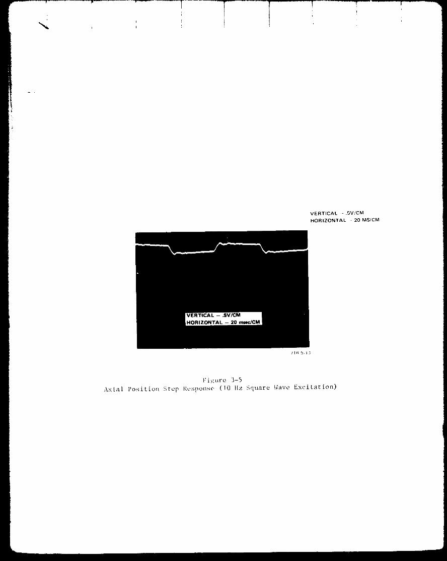
F-- 7!
I
VERTICAL - .SV/CM
HORIZONTAL - 20 MS/CM
11(:, 5-13
[:izure 3-5
Axial Position Step Response (I0 Hz Square Wave Excitation)

3.3 MBRW TORQUE CHARACTERISTICS
a. Spin Motor Torque
A two-phase, sine wave spin motor driver, set at 280 Hz, was used to run
the redundant segmented induction motor in the MBRW. The motor terminals were
connected so that the four windings that constitute each phase are in series-
parallel. Motor power was measured with a phase angle voltmeter reading the volt-
age across a I ohm resistor in series with Phase A and B. The phase angle volt-
meter thus measures motor winding current I cos 0. Power can then be calculated
by multiplying I cos 8 by the spin motor driver output voltage.
Spin motor torque was measured with a strain gauge reaction torque sen-
sor. Figure 3-6 is a curve of motor torque versus speed with the driver voltage
set for a minimum torque of .007 ft-lb (1.34 oz-in.) over ±700 rpm. The corres-
ponding motor power for this requirement is shown in Table 3-2. The torque curves
represent a net torque; motor torque less drag torque while accelerating, motor
torque plus drag torque while decelerating.
Figure 3-7 is the torque curve for a minimum of .02 ft-lb (3.84 oz-in.)
at any speed in any direction. Motor power for this level of torque is listed in
Table 3-3. Maximum motor power is 9.6 watts to maintain the required torque over
the ±700 rpm speed range.
b. Drag Torque
Initial testing revealed the rotor drag torque to be much larger than ex-
pected (.16 oz-in./1000 rpm versus .001 oz-in./1000 rpm). Preliminary investiga-
tion showed that the stray magnetic fields from the magnetic bearings were inter-
acting with the induction motor, thereby creating rotor drag. This was proven by
placing a partial magnetic shield (covering approximately 30 percent of motor) be-
tween each motor segment and the magnetic bearings. Curves I and 2 in Figure
3-8 show drag curves with and without shields. A 30 percent improvement resulted
with the partial shield. Further tests should be conducted to explore design
modifications that would reduce the drag torque in future designs. The first test
would investigate the effect of reversing one of the permanent magnets in the
bearings, thus changing the stray field pattern. It is expected that this will re-
duce the drag torque, but increase the external magnetic fields. Other modifica-
tions which shield the motor gap from the external fields are also possible. It
may be noted that the shaft power at 700 rpm corresponding to the measured drag
torque is only .058 watt.
3-5

o
o i
E
,M
It_o
I _'_•
=g
o[-4
o

t _..
1I
, i
N0
!_1/I I
_'--
'/II/I
11L[
'liII<3_0
UU
l llll llll lll
NI ZO| ]nouoJ.
\
z_°_Oo
oo
f-
/
0t-I-
_o_
A/
/
÷
uJ
+
o
IN0
r-.. ,_-I oO
(-_ 0
_J
_g
0
0
q,)

l i
4
IkJ,
00
q)
0o I,_I o
_'_ E._

?
_r
A.
B.
C,
STALL
PHASE A
Fwd
Rev
PHASE B
Fwd
Rev
400 RPM
PHASE A
Fwd
Rev
PHASE B
Fwd
Rev
700 RPM
PHASE A
Fwd
Rev
PHASE B
Fwd
Rev
Icos 8 = .92 amp
Icos e = .058 amp
Icos @ = .072 amp
Icos 0 = .105 amp
Icos _ = .095 amp
Icos 0 = .053 amp
Icos 0 = .075 amp
Icos @ = .100 amp
Icos 0 = .085 amp
Icos _ = .058 amp
Icos 0 = .06 amp
Icos 0 = .095 amp
TABLE 3-2
P = I .96 watts
P = 1.23 watts
P = I .53 watts
P -- 2.24 watts
Total Power
P = 2.02 watt:_
P = 1.13 watts
P = 1.6 watts
P = 2.13 watts
Total Power
P = 1.81 watts
P = 1.06 watts
P = 1.28 watts
P = 2.02 watts
Total Power
h
Spin Motor Driver - 21.3 vac280 Hz
(Both Phases)
For a minimum torque of 1.34
oz-in, at any speed, ineither direction.
Fwd = 3.49 watts
Rev = 3.47 watts
Fwd = 3.62 watts
Rev = 3.26 watts
Fwd = 3.09 watts
Rev - 3.08 watts
3-6

t
Ao STALL
PHASE A
Fwd
Rev.
PHASE B
Fwd
Rev.
Icos 0 = .155 amp
Icos 8 = .09 amp
Icos 0 = .105 amp
Icos _ = .175 amp
B. 400 RPM
PHASE A
Fwd
Rev
PHASE B
Fwd
Rev
Icos 0 = .15 amp
Icos _ = .105 amp
Icos 0 = .108 amp
Icos 0 = .170 amp
C. 700 RPM
PHASE A
Fwd
Rev
PHASE B
Fwd
Rev
Icos 0 = .152 amp
Icos 0 = .085 amp
Icos 0 = .100 amp
Icos 0 - .162 amp
TABLE 3-3
Spin Motor Driver - 34.75 vac280 Hz
(Both Phases)
For a minimum torque of 3.84
oz-ln, at any speed in either
P = 5.39 watts direction.
P = 3.13 watts
P = 3.65 watts
P = 6.1 watts
Total Power Fwd = 9.04 watts
Rev = 9.23 watts
P = 5.21 watts
P = 3.65 watts
P = 3.65 watts
P = 5.91 watts
Total Power Fwd = 8.86 watts
Rev = 9.56 watts
P = 5.28 watts
P = 2.95 watts
P = 3.47 watts
P = 5.63 watts
Total Power Fwd = 8.75 watts
Rev = 8.58 watts
3-7

Whenoperated on its touchdownball-bearings, a relatively flat torque
increase of ,13 oz-in° was measuredover a 300 to 700 rpm speed range.
3.4 TACHOMETER
As described in Section 2.8 the dual channel tachometer provides 520 pulses
per revolution for speed determination and a direction of rotation indication.
The pulses are shownin Figure 3-9 at a rotor speed of 700 rpm. This signal is
the summationof the processed output of two special Bently-Nevada eddy-current
probes which sense 130 teeth machinedon the inside of the rotor. They are
aligned such that their outputs are spaced approximately 90 electrical degrees
apart.
The tachometer output pulses are 40 microseconds wide and 3.4 volts in
amplitude. The unevenspacing between pulses arises from minor variations in
land and groove widths. There is virtually no deadbandin accurate speed outputas the rotor crosses 0 rpm in changing direction of rotation. Error-free rota-
tional direction information is also provided through 0 rpm. The power required
for a single tachometer channel was .396 watt.
3-8

VERTICAL - 1V/DIV
HORIZONTAL - 2MS/DIV
716-5-14
t i+'_ir_,{-¢)

q
SECTION 4.0
CONCLUSIONS AND RECOMMENDATIONS

I I
SECTION 4.0
CONCLUSIONS AND RECOMMENDATIONS
The experience gained during the construction and test of the engineering
model indicates that a magnetically suspended reaction wheel is indeed appli-
cable to interplanetary and orbiting spacecraft without appreciable penalties on
weight and power. The magnetic bearing provides the capability for reliable,
fully-redundant, low drag torque operation over the entire speed range, including
passage through zero speed. The remainder of this section details the conclusions
and outlines recommendations for further development activities.
a. Overall Performance
The concept of total redundancy of all MBRW functional systems was proven
to be feasible. Thus, a weight reduction is possible when compared with a space-
craft system which utilizes a second reaction wheel to avoid single-point failures.
The segmented stator construction proved the feasibility of this approach to in-
corporate motor redundancy. Similarly, the coils in each magnetic bearing were
shown to be independently capable of controlling the axial system, so that the
suspension redundancy scheme using two (redundant) position sensors and two chan-
nels of electronics is possible. The concept of using eddy-current probes to pro-
vide speed-indendent, high resolution speed sensing was demonstrated. Tachometer
redundancy was proven using two identical channels (sensors and electronics).
The most significant parameters constraining the design of the magnetic
bearing are the radial and angular stiffnesses, For the requirements of the speci-
fication, the angular resonance frequency constraint was the most stringent, and
influenced the bearing design and hence the bearing weight. Thus, it is necessary
to examine constraints on stiffness more carefully than in a conventional reaction
wheel design.
Testing and evaluation of the MBRW design revealed no major shortcomings
in the areas of assembly and bench operation. The design can be used directly
as a basis for a flight prototype design. The overall weight may be decreaseJ bv
.7 - .8 pound by the substitution of magnesium for aluminum as the material for the
housings and cover. An equal weight decrease is possible if the maximum operatin_
speed is allowed to increase to 1000 rpm; the motor power would remain within the
specified requirement. A slight redesign of the configuration to eliminate the
4-I

I
! I
offset of the center-of-mass from the mid-point of the bearing span would enable
the achievement of Ig support with spin axis horizontal. The weight sensitivities
of the design to motor power and angular momentum are: .2 ib/watt and 4.4
Ib/ft-lb-sec, respectively.
The effect of structural compliance in the rotor, housing or in the mount-
ing has the effect of introducing gain and phase peaking in the axial control loop.
The web in the lower housing, for example, gave rise to a mode at 200 to 300 Hz
which would necessitate complex compensation to assure axial system stability. An
MBRW mount bypassing this compliance was used as the interim solution; thickenin_
of the web to increase the structural resonance frequency is the solution for future
designs. In general, the location of structural resonances below 50 Hz and above
600 Hz would be distant enough from phase crossover that single lead-lag compensa-
tion could be used. Of the two alternative spacecraft mountings, soft mounting is
likely to be the more practicable approach. It is recommended that investigation
of the mounting-axial system interaction be included in future development.
b. Magnetic Bearings
The angular stiffness of the bearing system was an order of 4 lower than
that predicted. The relationship between geometry (bearing diameter, span) in
magnetic bearing systems needs to be experimentally confirmed in order to imple-
ment suitable design modifications to increase the angular resonance frequency.
The inherent non-linearity in the control force-to-control current gain
in a one-loop bearing system (if only one control coil is used) can be overcom_
by the use of a split-coil design, where half the winding in each bearing is at
any time used for control. The failure modes in such a scheme need +o be analvzed
and experimentally tested to determine the effects on reliability. The use of
split coils would also decrease the total current required for lift-off and hence
lift-off power.
c. Motor
The weight efficiency of using the large-diameter, segmented _c induction
motor concept was demonstrated. The discrepancy in drag torque appeared to be re-
lated to the interaction of the magnetic bearing stray fields with the segmented
stators. The variation of motor gap fields as a function of angle around the p_,ri-
phery can cause additional eddy-current losses in the motor cage, leading to ;n-
creased drag torque. The stray field pattern can be altered by reversin_ the
4-2

polarity of the permanent magnet in one bearing, with possible increase in the
total external magnetic field and a decreased drag torque. Investigations aimed
at drag torque reduction are recommended.
If it is desired to decrease the motor power further or to achieve a con-
stant torque over the speed range, the possibility of using a DC brushless motor
should be investigated. An ironless armature construction for such a motor would
eliminate the radial unbalance otherwise characteristic of DC brushless motors.
d. Tachometer
The concept using eddy-current sensing of a periodic machined rotor pro-
file was proven to be feasible. Further increase in tachometer resolution using
this concept, however, appears difficult because of the difficulty of generating
pulses of sufficient amplitude if the number of machined teeth is made any larger.
A 15 percent increase in re_olution would be possible if the diameter at the
teeth was increased to the outside rim diameter.
e. Control System and Electronics
The use of single lead-lag compensation was demonstrated to be adequate
in the absence of structural resonances in the region of phase crossover. In-
vestigation in the following areas are recommended in order to decrease the
total power consumption further:
• Use of an annular ring axial position sensor to eliminate
angular mode coupling and the effect of run-out.
• Methods for decreasing the standby currents required to eliminate
crossover distortion in the power amplifier.
• Possibility of using pulse width modulation in the amplifier.
4-3

.......
i!
SECTION 5.0
NEW TECHNOLOGY

I
........1 ! ........'......I
SECTION 5.0
NEW TECHNOLOGY
The technical information contained in this report is based on prior develop-
ments at Sperry Flight Systems, in the areas of reaction wheel assemblies, motors
and magnetic bearings. There was no new technology developed during the course of
this contract.
5-I

I
APPENDIX A
ROTOR BALANCING TECHNIQUE
I
APPENDIX A
ROTOR BALANCING TECHNIQUE
Balancing of the MBRW rotor assembly involved some complications which are
not usually encountered in balancing reaction wheel rotors:
• The rotor assembly center of gravity is offset axially from the
suspension system spring and geometric centers.
• The balance correction plans are not symmetrically placed with
respect to the rotor center of gravity.
• The radial proximity sensors which are used to measure rotor dis-
placements, cannot be equally placed with respect to the rotor
center of gravity or the bearing centers.
Previous balancing work with magnetically suspended rotors has involved
symmetrical rotors having none of the complications listed above. This work used
the fact that the low stiffness and low damping of magnetic bearings results in
fairly large, easily sensed motions near critical speeds. The units were equipped
with proximity sensors near each end of the shaft which gave indications of the
shaft-end-motion (phase and amplitude). This sensing scheme is shown in Figure
A-I. Since the proximity sensor voltage and phase information indicates total
shaft-end-motions, a correction for zero-speed runout must be made to obtain the
net unbalance effects. The net unbalance is then resolved into static and dy-
namic unbalance. This procedure is illustrated in Figure A-2.
If the rotor, suspension and balance planes are symmetric, the static and
dynamic indications can be used to determine sensitivities and make balance cor-
rections directly. In case of this MBRW, the same general procedure can be
followed, but the resolution of the total unbalance into static and dynamic com-
ponents requires decoupllng of non-symmetric effects listed in the first para-
graph. This coupling problem can be handled by relating the apparent unbalan¢_
directly to the required correction weiRhts through influence coefflcients, a..:11
W I = a11S' + a12 D' (A-I)
S' + D'W2 = a21 a22 (A-2)
A-1

/ \ I " PHASE
_ REFERENCE
PROXIMITY •
s_o_s _ -_o_o;_,_
0 o
v 2¢
815-49 30
Figure A-1
Sensing Rotor Motions Due to Unbalance

1 I
4 _
soo
• u1
180 ° 0o
R2 1 v2
V - OBSERVED MOTIONS
R - 0 SPEED RUNOUTS
U - UNBALANCE EFFECTS
270 °
SEPARATION OF RUNOUT
AND UNBALANCE EFFECTS
90 o
01
S - STATIC UNBALANCE VECTORS
D - D_NAMIC UNBALANCE VECTORS
D2
270 °
SEPARATION OF STATIC
ANO DYNAMIC UNBALANCES
Figure A-2
Balancing Phasor Diagrams

I
I
#
where
W I and W 2 are the correction weights for plane I and plane 2
This relationship applies to a given phase plane in the rotor for a given speed.
It can be generalized, giving,
or using matrix notation,
where
S' + D' (A-3)W I = a]1 a12
-- S' + D' (A-4)W2 a21 a2 2
['_] = [a] [_"] (A-5)
[U '] = (A-6)
LD'_
arid the alj values can be determined by trial weight additions to each of the
balance planes. Since it was also required that the actual static and dynamic
unbalance levels be known, another relationship is required which relates the
actual unbalance to weights in the two correction planes.
1_'] --[b] [W-*] (A-7)
Here
[ul =
The bij values are determined directly from the geometry of the rotor and the
placement of the correction planes.
A direct relationship can be formed between indicated and actual unbalance
from equations A-5 and A-7.
[ul = [BI [u'i (A-S)
whe re
[B] = lbl lal (A-9)
A-2

l T ,J
For the MBRW in its final configuration, the values of the coefficient matrices are:
[a] ffi[-11 .015
L2 .593
2.53| ] at 950 rpm
-3.52 J(A-10)
[b]., [ "1336 "1336 10103 -.0835J
(A-I I)
[BI = .211 -.132] at 950rpm
J-.227 .320
(A-I 2)
The 50 percent overspeed point, 950 rpm, was chosen to obtain increased
sensitivity over the sensitivities at 700 rpm nominal operating speed.
Besides relating correctimn weights to the unbalance, the influence coeffi-
cient matrices [a] and [B] also include unit conversion factors and the calibra-
tion factors of each of the two radial proximity sensors. In the above matrices,
the unbalance indications [U'] are in terms of proximity sensor voltages, the2
weights [U] are in grams and the unbalance [_] is in oz-in, and oz-in.
During the trial balancing, using lead tape to make corrections, it was found
that using equation A-5 directly to determine correction weights, both static and
dynamic unbalance levels were reduced by approximately the same factor.
The original unbalance levels in the rotor assembly were determined to be .13
oz-in 2 dynamic and .12 oz-in static. The final balance was achieved after two
iterations and the residual unbalance levels are .019 oz-in 2 and .0035 oz-in.
A-3

APPENDIX B
INFLUENCE OF STRUCTURE ON THE SUSPENSION S¥STEH

APPENDIX B
INFLUENCE OF STRUCTURE ON THE SUSPENSION SYSTEM
The interaction of the suspension system with structural modes in the rotor
and/or the housing can lead to complexity of the control compensation; these
structural modes must therefore be designed to be outside a critical frequency
band.
Examination of the axial open-loop frequency response of several magnetic
suspensions at Sperry shows
(I) at several frequencies, there is a peaking of the phase
characteristics where a bell-shaped characteristic is
observed ;
(2) at each of these frequencies, there is a gain notch followed
by a gain peak.
These effects are caused by flexibilities in the housing mounting and/or in
the rotor structure. The result of these structural modes is to render the task
of axial stabilization of the control system more complex if the modes occur in
the region of the phase crossover of the compensated characteristic. Thus,
a structural mode may necessitate the use of double lead-lag compensation rather
than a single lead-lag.
The analysis below incorporates a single housing flexibility in the
suspension model and shows the structural interaction. The effects of flexibility
in the rotor structure lead to analogous gain/phase characteristics, and a separ-
ate analysis is therefore not presented here.
This model, shown in Figure B-I, incorporates a single housing stiffness
and mass mH in addition to the simple rigid body magnetic bearing model
m z - kU z - Fex t + F .
The equations of motion are
mz - ku (z - zH) = F + Fc ext
mH zH + k H zH + kU (z - zH) -- -F c (B-I)
B-I

m H
ZH
Fex t
_Z
815 4922
Figure B-I
Structural Model to Illustrate Effect of Housing Flexibility

where
m = the suspended mass (rotor mass)
= the unbalance stiffness
F -- the axial control forcec
Fex t = the external force
z = the inertial displacement of the rotor
and
zH = the inertial displacement of the housing
The position sensor, mounted on the housing, senses the relative displace-
ment (z - ZH). This relative displacement is used to generate an appropriate
control force F to overcome the axial instability. The open-loop transferc
function may be determined as
z - zH
F 4c mmHs
(mH + m) s2 + kH= (B-2)
+ s2 [_ m- _(m H + m)] - _
It can be seen that the case _ _ o= gives back the simple model in which
z - zH im
F 2c ms -_
The open-loop transfer function, equation (B-2), has a pair of imaginary zeros at
I/2
, a pair of imaginary poles, and two real poles, one of which is
in the right-half plane (showing the static instability). Application of the
Routh-Hur_itz criteria shows that the imaginary poles are always greater in
magnitude than the imaginary zeros, as shown in Figure B-2. This means that the
open-loop frequency response will include a phase peak (lead) and a notch-peak
in the gain curve, as shown in Figure B-3.
B-2

-- × o
REAL POLES - SUSPENSION
IMAGONARY POLES%
STRUCTUREIMAGINARY ZEROS _
716-5-25
Figure B-2
Pole Location due to Housing Flexibility

-180 °
HASE
716-5-26
Figure B-3
Effect of Flexibility on Open-Loop Response

The above analysis can be extended to the real case where the lumpedmodel
includes several masses and flexibilities; the open-loop response will then ex-
hibit the phase peak and the gain notch-peak at several frequencies, as observed
in actual measured responses.
Hence, for simplicity of stabilization, it is important to design beth hous-
ing and rotor structure so as to locate the structural modes either well below or
well above the open-loop rigid body poles ±J_,/m.¥ u
B-3