Embed Size (px)
Citation preview
A System, Tools and Algorithms for AdaptiveHTTP-live Streaming on Peer-to-peer Overlays
ROBERTO ROVERSO
Doctoral Thesis inInformation and Communication Technology
KTH - Royal Institute of TechnologyStockholm, Sweden, December 2013

TRITA-ICT/ECS AVH 13:18ISSN 1653-6363ISRN KTH/ICT/ECS/AVH-13/18-SEISBN 978-91-7501-915-4
KTH School of Information andCommunication Technology
SE-100 44 StockholmSWEDEN
Akademisk avhandling som med tillstånd av Kungl Tekniska högskolan framlägges tilloffentlig granskning för avläggande av Doktorandexamen i Informations- och Kommu-nikationsteknik Torsdagen den 12 Dec 2013 klockan 13.00 i Sal D, ICT School, KunglTekniska högskolan, Forum 105, 164 40 Kista, Stockholm.
© ROBERTO ROVERSO, December 2013
Tryck: Universitetsservice US AB
i
Abstract
In recent years, adaptive HTTP streaming protocols have become the de factostandard in the industry for the distribution of live and video-on-demand contentover the Internet. In this thesis, we solve the problem of distributing adaptive HTTPlive video streams to a large number of viewers using peer-to-peer (P2P) overlays.We do so by assuming that our solution must deliver a level of quality of user expe-rience which is the same as a CDN while trying to minimize the load on the contentprovider’s infrastructure. Besides that, in the design of our solution, we take intoconsideration the realities of the HTTP streaming protocols, such as the pull-basedapproach and adaptive bitrate switching.
The result of this work is a system which we call SmoothCache that providesCDN-quality adaptive HTTP live streaming utilizing P2P algorithms. Our experi-ments on a real network of thousands of consumer machines show that, besidesmeeting the the CDN-quality constraints, SmoothCache is able to consistently de-liver up to 96% savings towards the source of the stream in a single bitrate scenarioand 94% in a multi-bitrate scenario. In addition, we have conducted a number ofpilot deployments in the setting of large enterprises with the same system, albeittailored to private networks. Results with thousands of real viewers show that ourplatform provides an average offloading of bottlenecks in the private network of91.5%.
These achievements were made possible by advancements in multiple researchareas that are also presented in this thesis. Each one of the contributions is novelwith respect to the state of the art and can be applied outside of the context of ourapplication. However, in our system they serve the purposes described below.
We built a component-based event-driven framework to facilitate the develop-ment of our live streaming application. The framework allows for running the samecode both in simulation and in real deployment. In order to obtain scalability ofsimulations and accuracy, we designed a novel flow-based bandwidth emulationmodel.
In order to deploy our application on real networks, we have developed a net-work library which has the novel feature of providing on-the-fly prioritization oftransfers. The library is layered over the UDP protocol and supports NAT Traver-sal techniques. As part of this thesis, we have also improved on the state of the art ofNAT Traversal techniques resulting in higher probability of direct connectivity be-tween peers on the Internet.
Because of the presence of NATs on the Internet, discovery of new peers and col-lection of statistics on the overlay through peer sampling is problematic. Therefore,we created a peer sampling service which is NAT-aware and provides one order ofmagnitude fresher samples than existing peer sampling protocols.
Finally, we designed SmoothCache as a peer-assisted live streaming system basedon a distributed caching abstraction. In SmoothCache, peers retrieve video frag-ments from the P2P overlay as quickly as possible or fall back to the source of thestream to keep the timeliness of the delivery. In order to produce savings, the cachingsystem strives to fill up the local cache of the peers ahead of playback by prefetchingcontent. Fragments are efficiently distributed by a self-organizing overlay networkthat takes into account many factors such as upload bandwidth capacity, connec-tivity constraints, performance history and the currently being watched bitrate.


iii
Acknowledgements
I am extremely grateful to Sameh El-Ansary for the way he supported me during my PhDstudies. This thesis would not have been possible without his patient supervision andconstant encouragement. His clear way of thinking, methodical approach to problemsand enthusiasm are of great inspiration to me. He also taught me how to do researchproperly given extremely complex issues and, most importantly, how to make findingsclear for other people to understand.
I would like to acknowledge my supervisor Seif Haridi for giving me the opportunityto work under his supervision. His vast knowledge of the field and experience was ofmuch help to me. In particular, I take this opportunity to thank him for his guidance onthe complex task of combining the work as a student and as an employee of PeerialismAB.
I am grateful to Peerialism AB for funding my studies and to all the company’s verytalented members for their help: Riccardo Reale, Mikael Högqvist, Johan Ljungberg,Magnus Hedbeck, Alexandros Gkogkas, Andreas Dahlström, Nils Franzen, Amgad Naiem,Mohammed El-Beltagy, Magnus Hylander and Giovanni Simoni. Each one of them hascontributed to this work in his own way and has made my experience at the companyvery fruitful and enjoyable.
I would also like to acknowledge my colleagues at the Swedish Institute of ComputerScience and at the Royal Institute of Technology-KTH: Cosmin Arad, Tallat MahmoodShaffaat, Joel Höglund, Vladimir Vlassov, Ahmad Al-Shishtawy, Niklas Ekström, Fate-meh Rahimian, Amir Payberah and Sverker Janson. In particular, I would like to expressmy gratitude to Jim Dowling for providing me with invaluable feedback on the topics ofmy thesis and passionate support of my work.
A special thanks goes to all the people that have encouraged me in the last years andhave made my life exciting and cherishable: Christian Calgaro, Stefano Bonetti, TizianoPiccardo, Matteo Lualdi, Jonathan Daphy, Andrea Ferrario, Sofia Kleban, to name a fewand, in particular, Maren Reinecke for her love and continuous moral support.
Finally, I would like to dedicate this work to my parents, Sergio and Odetta, andclose relatives, Paolo and Ornella, who have, at all times, motivated and helped me inthe journey of my PhD.


To my family


This work was conducted at and funded by

CONTENTS
Contents ix
List of Figures xv
List of Tables xix
I Thesis Overview 1
1 Introduction 3
1.1 Motivation . . . . . . . . . . . . . . . . . . . . . . . . . . . . . . . . . . . . . 5
1.2 Contribution . . . . . . . . . . . . . . . . . . . . . . . . . . . . . . . . . . . . 6
1.3 Publications . . . . . . . . . . . . . . . . . . . . . . . . . . . . . . . . . . . . 10
2 Background 13
2.1 Live Streaming . . . . . . . . . . . . . . . . . . . . . . . . . . . . . . . . . . . 14
2.2 Peer-to-peer Live Streaming . . . . . . . . . . . . . . . . . . . . . . . . . . . 15
2.2.1 Overlay Construction . . . . . . . . . . . . . . . . . . . . . . . . . . 16
2.2.2 Data Dissemination . . . . . . . . . . . . . . . . . . . . . . . . . . . 20
2.2.3 Infrastructure-aided P2P Live Streaming . . . . . . . . . . . . . . . 21
2.3 Peer-to-peer Connectivity . . . . . . . . . . . . . . . . . . . . . . . . . . . . 23
2.4 Peer Sampling . . . . . . . . . . . . . . . . . . . . . . . . . . . . . . . . . . . 25
2.4.1 NAT-resilient PSSs . . . . . . . . . . . . . . . . . . . . . . . . . . . . 26
2.5 Transport . . . . . . . . . . . . . . . . . . . . . . . . . . . . . . . . . . . . . . 27
2.6 Development and Evaluation of Peer-To-Peer Systems . . . . . . . . . . . 29
2.6.1 Emulation of Bandwidth Allocation Dynamics . . . . . . . . . . . 30
ix
x CONTENTS
Bibliography 31
II Framework and Tools 43
3 Mesmerizer: An Effective Tool for a Complete Peer-to-peer Software Devel-opment Life-cycle 453.1 Introduction . . . . . . . . . . . . . . . . . . . . . . . . . . . . . . . . . . . . 473.2 The Mesmerizer framework . . . . . . . . . . . . . . . . . . . . . . . . . . . 503.3 Implementation . . . . . . . . . . . . . . . . . . . . . . . . . . . . . . . . . . 50
3.3.1 Scala Interface . . . . . . . . . . . . . . . . . . . . . . . . . . . . . . 533.4 Execution modes . . . . . . . . . . . . . . . . . . . . . . . . . . . . . . . . . 54
3.4.1 Simulation Mode . . . . . . . . . . . . . . . . . . . . . . . . . . . . . 543.4.2 Deployment Mode . . . . . . . . . . . . . . . . . . . . . . . . . . . . 55
3.5 Network Layer . . . . . . . . . . . . . . . . . . . . . . . . . . . . . . . . . . . 563.5.1 Deployment Configuration . . . . . . . . . . . . . . . . . . . . . . . 563.5.2 Simulation Configuration . . . . . . . . . . . . . . . . . . . . . . . . 57
3.6 Conclusion & Future Work . . . . . . . . . . . . . . . . . . . . . . . . . . . . 633.7 References . . . . . . . . . . . . . . . . . . . . . . . . . . . . . . . . . . . . . 64
4 Accurate and Efficient Simulation of Bandwidth Dynamics for Peer-To-PeerOverlay Networks 694.1 Introduction . . . . . . . . . . . . . . . . . . . . . . . . . . . . . . . . . . . . 714.2 Related Work . . . . . . . . . . . . . . . . . . . . . . . . . . . . . . . . . . . . 734.3 Contribution . . . . . . . . . . . . . . . . . . . . . . . . . . . . . . . . . . . . 754.4 Proposed Solution . . . . . . . . . . . . . . . . . . . . . . . . . . . . . . . . . 75
4.4.1 Bandwidth allocation . . . . . . . . . . . . . . . . . . . . . . . . . . 754.4.2 Affected subgraph algorithm . . . . . . . . . . . . . . . . . . . . . . 78
4.5 Evaluation . . . . . . . . . . . . . . . . . . . . . . . . . . . . . . . . . . . . . 824.5.1 Methodology . . . . . . . . . . . . . . . . . . . . . . . . . . . . . . . 824.5.2 Scalability . . . . . . . . . . . . . . . . . . . . . . . . . . . . . . . . . 834.5.3 Accuracy . . . . . . . . . . . . . . . . . . . . . . . . . . . . . . . . . . 86
4.6 Conclusion & Future Work . . . . . . . . . . . . . . . . . . . . . . . . . . . . 894.7 References . . . . . . . . . . . . . . . . . . . . . . . . . . . . . . . . . . . . . 90
III Network Layer 93
5 NATCracker: NAT Combinations Matter 955.1 Introduction . . . . . . . . . . . . . . . . . . . . . . . . . . . . . . . . . . . . 975.2 Related Work . . . . . . . . . . . . . . . . . . . . . . . . . . . . . . . . . . . . 985.3 NAT Types as Combinations of Policies . . . . . . . . . . . . . . . . . . . . 98
5.3.1 Mapping Policy . . . . . . . . . . . . . . . . . . . . . . . . . . . . . . 995.3.2 Allocation Policy. . . . . . . . . . . . . . . . . . . . . . . . . . . . . . 100
CONTENTS xi
5.3.3 Filtering Policy. . . . . . . . . . . . . . . . . . . . . . . . . . . . . . . 1005.3.4 The Set of NAT Types . . . . . . . . . . . . . . . . . . . . . . . . . . 101
5.4 NAT Type Discovery . . . . . . . . . . . . . . . . . . . . . . . . . . . . . . . . 1015.5 NAT Traversal Techniques . . . . . . . . . . . . . . . . . . . . . . . . . . . . 1025.6 Simple hole-punching (SHP) . . . . . . . . . . . . . . . . . . . . . . . . . . . 102
5.6.1 Traversal Process . . . . . . . . . . . . . . . . . . . . . . . . . . . . . 1025.6.2 SHP Feasibility . . . . . . . . . . . . . . . . . . . . . . . . . . . . . . 1025.6.3 Coverage of SHP . . . . . . . . . . . . . . . . . . . . . . . . . . . . . 103
5.7 Prediction . . . . . . . . . . . . . . . . . . . . . . . . . . . . . . . . . . . . . . 1035.7.1 Prediction using Contiguity (PRC) . . . . . . . . . . . . . . . . . . . 1035.7.2 Prediction using Preservation (PRP) . . . . . . . . . . . . . . . . . . 1055.7.3 Prediction-on-a-Single-Side Feasibility . . . . . . . . . . . . . . . . 1055.7.4 Coverage of PRP & PRC . . . . . . . . . . . . . . . . . . . . . . . . . 106
5.8 Interleaved Prediction on Two Sides . . . . . . . . . . . . . . . . . . . . . . 1065.8.1 Traversal Process . . . . . . . . . . . . . . . . . . . . . . . . . . . . . 1075.8.2 Interleaved Prediction Feasibility . . . . . . . . . . . . . . . . . . . 1085.8.3 Interleaved Prediction Coverage . . . . . . . . . . . . . . . . . . . . 108
5.9 Evaluation . . . . . . . . . . . . . . . . . . . . . . . . . . . . . . . . . . . . . 1085.9.1 Distribution of Types . . . . . . . . . . . . . . . . . . . . . . . . . . 1095.9.2 Adoption of BEHAVE RFC . . . . . . . . . . . . . . . . . . . . . . . . 1095.9.3 Success Rate . . . . . . . . . . . . . . . . . . . . . . . . . . . . . . . . 1095.9.4 Time to traverse . . . . . . . . . . . . . . . . . . . . . . . . . . . . . 110
5.10 Conclusion & Future Work . . . . . . . . . . . . . . . . . . . . . . . . . . . . 1105.11 Acknowledgments . . . . . . . . . . . . . . . . . . . . . . . . . . . . . . . . . 1115.12 References . . . . . . . . . . . . . . . . . . . . . . . . . . . . . . . . . . . . . 111
6 DTL: Dynamic Transport Library for Peer-To-Peer Applications 1136.1 Introduction . . . . . . . . . . . . . . . . . . . . . . . . . . . . . . . . . . . . 1156.2 Related Work . . . . . . . . . . . . . . . . . . . . . . . . . . . . . . . . . . . . 1176.3 Contribution . . . . . . . . . . . . . . . . . . . . . . . . . . . . . . . . . . . . 1186.4 Dynamic Transport Library (DTL) . . . . . . . . . . . . . . . . . . . . . . . . 119
6.4.1 Polite Mode . . . . . . . . . . . . . . . . . . . . . . . . . . . . . . . . 1206.4.2 Variable Mode . . . . . . . . . . . . . . . . . . . . . . . . . . . . . . 122
6.5 Evaluation . . . . . . . . . . . . . . . . . . . . . . . . . . . . . . . . . . . . . 1226.5.1 Polite Mode results . . . . . . . . . . . . . . . . . . . . . . . . . . . . 1236.5.2 Variable Mode results . . . . . . . . . . . . . . . . . . . . . . . . . . 125
6.6 Conclusion . . . . . . . . . . . . . . . . . . . . . . . . . . . . . . . . . . . . . 1286.7 References . . . . . . . . . . . . . . . . . . . . . . . . . . . . . . . . . . . . . 129
IV Peer Sampling 131
7 Through the Wormhole: Low Cost, Fresh Peer Sampling for the Internet 1337.1 Introduction . . . . . . . . . . . . . . . . . . . . . . . . . . . . . . . . . . . . 136
xii CONTENTS
7.2 System Model . . . . . . . . . . . . . . . . . . . . . . . . . . . . . . . . . . . 1377.3 Background and Related Work . . . . . . . . . . . . . . . . . . . . . . . . . . 1387.4 Wormhole Peer Sampling Service . . . . . . . . . . . . . . . . . . . . . . . . 139
7.4.1 WPSS Architecture . . . . . . . . . . . . . . . . . . . . . . . . . . . . 1407.4.2 Wormhole Peer Sampling Skeleton . . . . . . . . . . . . . . . . . . 142
7.5 Analytical comparison . . . . . . . . . . . . . . . . . . . . . . . . . . . . . . 1437.5.1 Metrics of Quality of Service and Cost . . . . . . . . . . . . . . . . . 1437.5.2 Analysis of Existing PSS Algorithms . . . . . . . . . . . . . . . . . . 144
7.6 Evaluation . . . . . . . . . . . . . . . . . . . . . . . . . . . . . . . . . . . . . 1467.6.1 Experimental Setup: Simulation . . . . . . . . . . . . . . . . . . . . 1477.6.2 Experimental Setup: Deployment . . . . . . . . . . . . . . . . . . . 1477.6.3 Freshness . . . . . . . . . . . . . . . . . . . . . . . . . . . . . . . . . 1497.6.4 Randomness . . . . . . . . . . . . . . . . . . . . . . . . . . . . . . . 1507.6.5 Inter-arrival Time of Advertisements . . . . . . . . . . . . . . . . . 1517.6.6 Robustness to Different Churn Patterns . . . . . . . . . . . . . . . 1517.6.7 Comparison with Croupier . . . . . . . . . . . . . . . . . . . . . . . 153
7.7 Conclusions and Future Work . . . . . . . . . . . . . . . . . . . . . . . . . . 1557.8 References . . . . . . . . . . . . . . . . . . . . . . . . . . . . . . . . . . . . . 156
V Peer-To-Peer Streaming Agent Design 159
8 SmoothCache: HTTP-Live Streaming Goes Peer-To-Peer 1618.1 Introduction . . . . . . . . . . . . . . . . . . . . . . . . . . . . . . . . . . . . 1638.2 The Shift from RTP/RTSP to HTTP . . . . . . . . . . . . . . . . . . . . . . . 1648.3 Impact of the Shift on P2PLS Algorithms . . . . . . . . . . . . . . . . . . . . 1678.4 Related Work . . . . . . . . . . . . . . . . . . . . . . . . . . . . . . . . . . . . 1678.5 P2PLS as a Caching Problem . . . . . . . . . . . . . . . . . . . . . . . . . . . 1688.6 Beyond Baseline Caching . . . . . . . . . . . . . . . . . . . . . . . . . . . . . 1698.7 Proactive Caching . . . . . . . . . . . . . . . . . . . . . . . . . . . . . . . . . 1718.8 Evaluation . . . . . . . . . . . . . . . . . . . . . . . . . . . . . . . . . . . . . 172
8.8.1 Deployment Results . . . . . . . . . . . . . . . . . . . . . . . . . . . 1738.9 Conclusion . . . . . . . . . . . . . . . . . . . . . . . . . . . . . . . . . . . . . 1768.10 References . . . . . . . . . . . . . . . . . . . . . . . . . . . . . . . . . . . . . 178
9 SmoothCache 2.0: CDN-quality adaptive HTTP live streaming on P2P overlays1819.1 Introduction . . . . . . . . . . . . . . . . . . . . . . . . . . . . . . . . . . . . 1839.2 Related Work . . . . . . . . . . . . . . . . . . . . . . . . . . . . . . . . . . . . 1859.3 System Architecture . . . . . . . . . . . . . . . . . . . . . . . . . . . . . . . . 186
9.3.1 Baseline caching . . . . . . . . . . . . . . . . . . . . . . . . . . . . . 1879.3.2 PLS Agent . . . . . . . . . . . . . . . . . . . . . . . . . . . . . . . . . 1879.3.3 Server Infrastructure . . . . . . . . . . . . . . . . . . . . . . . . . . . 189
9.4 Beyond Baseline Caching . . . . . . . . . . . . . . . . . . . . . . . . . . . . . 1909.4.1 The Window of Opportunity . . . . . . . . . . . . . . . . . . . . . . 190
CONTENTS xiii
9.4.2 Exploiting the window of opportunity . . . . . . . . . . . . . . . . 1909.4.3 Overlay Construction . . . . . . . . . . . . . . . . . . . . . . . . . . 1929.4.4 Peer Sampling . . . . . . . . . . . . . . . . . . . . . . . . . . . . . . . 1929.4.5 In-partners Selection . . . . . . . . . . . . . . . . . . . . . . . . . . 1929.4.6 Out-partners selection . . . . . . . . . . . . . . . . . . . . . . . . . . 194
9.5 Prefetching . . . . . . . . . . . . . . . . . . . . . . . . . . . . . . . . . . . . . 1959.5.1 Proactive prefectching . . . . . . . . . . . . . . . . . . . . . . . . . . 1959.5.2 Reactive prefectching . . . . . . . . . . . . . . . . . . . . . . . . . . 197
9.6 Evaluation . . . . . . . . . . . . . . . . . . . . . . . . . . . . . . . . . . . . . 1979.6.1 Test-bed . . . . . . . . . . . . . . . . . . . . . . . . . . . . . . . . . . 1989.6.2 Experiments . . . . . . . . . . . . . . . . . . . . . . . . . . . . . . . . 200
9.7 Conclusion . . . . . . . . . . . . . . . . . . . . . . . . . . . . . . . . . . . . . 2059.8 References . . . . . . . . . . . . . . . . . . . . . . . . . . . . . . . . . . . . . 206
10 SmoothCache Enterprise: Adaptive HTTP Live Streaming in Large PrivateNetworks 20910.1 Introduction . . . . . . . . . . . . . . . . . . . . . . . . . . . . . . . . . . . . 21110.2 Challenges . . . . . . . . . . . . . . . . . . . . . . . . . . . . . . . . . . . . . 21210.3 System Overview . . . . . . . . . . . . . . . . . . . . . . . . . . . . . . . . . . 213
10.3.1 Overlay Construction . . . . . . . . . . . . . . . . . . . . . . . . . . 21310.3.2 Delivery . . . . . . . . . . . . . . . . . . . . . . . . . . . . . . . . . . 213
10.4 Differences between SmoothCache 2.0 and SmoothCache enterprise . . . 21410.5 Preliminary results . . . . . . . . . . . . . . . . . . . . . . . . . . . . . . . . 214
10.5.1 About Deployments . . . . . . . . . . . . . . . . . . . . . . . . . . . 21510.5.2 Pilot Event: US-based company . . . . . . . . . . . . . . . . . . . . 216
10.6 References . . . . . . . . . . . . . . . . . . . . . . . . . . . . . . . . . . . . . 220
11 Conclusions 22311.1 Future Work . . . . . . . . . . . . . . . . . . . . . . . . . . . . . . . . . . . . 22711.2 References . . . . . . . . . . . . . . . . . . . . . . . . . . . . . . . . . . . . . 228
Appendices 231
12 Traversal Sequence Diagrams 233

LIST OF FIGURES
Introduction
1.1 Layered view of the SmootchCache system . . . . . . . . . . . . . . . . . . . . 7
2.1 Representation of a tree-based overlay structure . . . . . . . . . . . . . . . . . 162.2 Representation of a multi-tree-based overlay structure . . . . . . . . . . . . . 162.3 Representation of a mesh-based overlay structure . . . . . . . . . . . . . . . . 18
Mesmerizer: An Effective Tool for a Complete Peer-to-peer Software Develop-ment Life-cycle
3.1 Example Component Interface and implementations . . . . . . . . . . . . . . 513.2 The structure of the Mesmerizer Framework . . . . . . . . . . . . . . . . . . . 533.3 The structure of our Bittorrent Application . . . . . . . . . . . . . . . . . . . . 543.4 Performance comparison for structured network overlays with 1000 nodes
and different number of outgoing flows per node. . . . . . . . . . . . . . . . . 613.5 Performance comparison for structured network overlays with varying size
and 20 outgoing flows per node. . . . . . . . . . . . . . . . . . . . . . . . . . . . 62
Accurate and Efficient Simulation of Bandwidth Dynamics for Peer-To-Peer Over-lay Networks
4.1 An example of the max-min bandwidth allocation algorithm. . . . . . . . . . 774.2 An example of the affected subgraph discovery. . . . . . . . . . . . . . . . . . . 824.3 Simulation times of a random network overlay. 1000 nodes network size and
varying number of outgoing flows per node. . . . . . . . . . . . . . . . . . . . . 834.4 Simulation times for a DHT-like structured network overlay. 1000 nodes and
varying number of outgoing flows per node. . . . . . . . . . . . . . . . . . . . . 844.5 Simulation time for varying sizes of a random overlay networks with a fixed
20 outgoing flows per node. . . . . . . . . . . . . . . . . . . . . . . . . . . . . . 854.6 Simulation time for different sizes of a structured overlay networks with fixed
20 outgoing flows per node. . . . . . . . . . . . . . . . . . . . . . . . . . . . . . 85
xv

xvi LIST OF FIGURES
4.7 Performance improvement when using the affected subgraph algorithm onrandom network overlays with 1000 nodes and different number of outgoingflows per node. . . . . . . . . . . . . . . . . . . . . . . . . . . . . . . . . . . . . . 86
4.8 Performance improvement when using the affected subgraph algorithm onrandom network overlays with varying size and 20 outgoing flows per node. . 87
4.9 Performance improvement when using the affected subgraph algorithm onstructured network overlays with 1000 nodes and different number of outgo-ing flows per node. . . . . . . . . . . . . . . . . . . . . . . . . . . . . . . . . . . . 87
4.10 Performance improvement when using the affected subgraph algorithm onstructured network overlays with varying size and 20 outgoing flows per node. 88
NATCracker: NAT Combinations Matter
5.1 All possible distinct NAT types combinations for two peers a and b withthe technique needed to traverse the combination and X for un-traversablecombinations. SHP(*), PRC(*) and PRP(*) stand respectively for Simple HolePunching, Port Prediction using Contiguity and Port Prediction using Preser-vation. Combinations of NAT behaviors mandated by RFC 4787 are identi-fied by the label BEHAVE in the table’s legend. . . . . . . . . . . . . . . . . . . 104
5.2 Distribution of encountered NAT types in τ as (m, f ,a) . . . . . . . . . . . . . 1075.3 Success rate of each technique averaged over all applicable combinations. . 1095.4 Time taken (in msec) for the traversal process to complete. . . . . . . . . . . . 110
DTL: Dynamic Transport Library for Peer-To-Peer Applications
6.1 Comparison of Polite Mode intra-protocol fairness with AIAD (a) as opposedto with AIMD (b) . . . . . . . . . . . . . . . . . . . . . . . . . . . . . . . . . . . . 124
6.2 Temporal evolution of the throughput of 10 DTL 0 flows on the path planet-lab1.sics.se - planet2.zib.de . . . . . . . . . . . . . . . . . . . . . . . . . . . . . . 125
6.3 Temporal evolution of the throughput of two DTL flows pr i or i t y = 0 (fixed)and two TCP flows on the Planetlab testing configuration . . . . . . . . . . . . 125
6.4 Plot of the relative Throughput (a) and the Intra-protocol Fairness (b) as afunction of pr i or i t y . . . . . . . . . . . . . . . . . . . . . . . . . . . . . . . . . 126
6.5 Temporal evolution of the throughput of two DTL flows pr i or i t y = 1 (fixed)and two TCP flows on the Planetlab testing configuration . . . . . . . . . . . . 127
6.6 Temporal evolution of the throughput of two dynamic priority DTL(0,1,2)flows which share the bottleneck link with a TCP flow . . . . . . . . . . . . . . 128
6.7 Temporal evolution of the throughput of six DTL flows with varying pr i or i t yvalue . . . . . . . . . . . . . . . . . . . . . . . . . . . . . . . . . . . . . . . . . . . 128
Through the Wormhole: Low Cost, Fresh Peer Sampling for the Internet
7.1 WPSS layered architecture. . . . . . . . . . . . . . . . . . . . . . . . . . . . . . . 139
LIST OF FIGURES xvii
7.2 The Base Overlay contains stable links between nodes (bottom layer). Worm-holes (the thick line on the upper layer) are created to public nodes. The up-per layer also illustrates a private node placing two advertisements at neigh-boring nodes to the wormhole. . . . . . . . . . . . . . . . . . . . . . . . . . . . 141
7.3 Average hop count in simulation, with real deployment input data . . . . . . 1487.4 Time to publish 20 ads per peer . . . . . . . . . . . . . . . . . . . . . . . . . . . 1487.5 In-degree measurements . . . . . . . . . . . . . . . . . . . . . . . . . . . . . . . 1497.6 Clustering coefficient measurements . . . . . . . . . . . . . . . . . . . . . . . . 1507.7 Inter-arrival time measurements . . . . . . . . . . . . . . . . . . . . . . . . . . 1517.8 Flash crowd scenario for different sizes of flash crowd. . . . . . . . . . . . . . 1527.9 Catastrophic failure scenarios in WPSS for different ratios of failed nodes. . . 1537.10 WPSS under churn scenarios with varying levels of churn. . . . . . . . . . . . 1547.11 Comparison between WPSS and Croupier. . . . . . . . . . . . . . . . . . . . . . 155
SmoothCache: HTTP-Live Streaming Goes Peer-To-Peer
8.1 Sample Smooth streaming Manifest . . . . . . . . . . . . . . . . . . . . . . . . 1658.2 Client-Server interactions in Microsoft Smooth Streaming . . . . . . . . . . . 1668.3 Comparison of traffic savings with different algorithm improvements . . . . 1738.4 Comparison of cumulative buffering time for source only and improvements 1748.5 Breakdown of traffic quantities per bitrate for: (a) A network with P2P caching,
Source & P2P traffic summed together. (b) The same P2P network with source& P2P traffic reported separately, and (c) A network with no P2P. . . . . . . . . 175
8.6 Breakdown of traffic quantities per bitrate using baseline . . . . . . . . . . . . 1758.7 Comparison of savings between different in-partners number . . . . . . . . . 1768.8 Savings for single bitrate runs . . . . . . . . . . . . . . . . . . . . . . . . . . . . 1768.9 Buffering time for single bitrate runs . . . . . . . . . . . . . . . . . . . . . . . . 177
SmoothCache 2.0: CDN-quality adaptive HTTP live streaming on P2P overlays
9.1 PLS agent architecture . . . . . . . . . . . . . . . . . . . . . . . . . . . . . . . . 1889.2 (a) All peers watching from the CDN and have access to the contents µ sec-
onds after creation, (b) Peers of different bandwidth classes prefetching piecesin the order of their bandwidth and then viewing it at the same time as theywould do from the CDN. . . . . . . . . . . . . . . . . . . . . . . . . . . . . . . . 189
9.3 Test network bandwidth distribution . . . . . . . . . . . . . . . . . . . . . . . . 1989.4 Single bitrate, resource-rich scenario . . . . . . . . . . . . . . . . . . . . . . . . 1999.5 Single bitrate, resource-poor scenario . . . . . . . . . . . . . . . . . . . . . . . 2009.6 Multi-bitrate . . . . . . . . . . . . . . . . . . . . . . . . . . . . . . . . . . . . . . 2019.7 Cumulative buffering . . . . . . . . . . . . . . . . . . . . . . . . . . . . . . . . . 2029.8 Cumulative traffic split . . . . . . . . . . . . . . . . . . . . . . . . . . . . . . . . 2029.9 Classification of cumulative peer-to-peer transferred data per bandwidth class2039.10 Scenario 1% churn . . . . . . . . . . . . . . . . . . . . . . . . . . . . . . . . . . . 2049.11 Massive failure scenario . . . . . . . . . . . . . . . . . . . . . . . . . . . . . . . . 205
xviii LIST OF FIGURES
SmoothCache Enterprise: Adaptive HTTP Live Streaming in Large Private Net-works
10.1 HTTP live delivery in a private network with our solution . . . . . . . . . . . . 21410.2 Evolution of number of viewers, Real event . . . . . . . . . . . . . . . . . . . . 21510.3 Savings towards the source of the stream, Real Event . . . . . . . . . . . . . . . 21610.4 Average buffering time over all peers, Real Event . . . . . . . . . . . . . . . . . 21710.5 Evolution of number of viewers, Instrumented Test . . . . . . . . . . . . . . . 21710.6 Savings towards the source of the stream, Instrumented Test . . . . . . . . . . 21810.7 Average savings CDF for all network segments, Instrumented Test . . . . . . . 21810.8 Locality percentage CDF for all network segments, Instrumented Test . . . . 21910.9 Cumulative buffering time classification, Instrumented Test . . . . . . . . . . 21910.10 Overlay visualization, Instrumented Test . . . . . . . . . . . . . . . . . . . . . . 221
LIST OF TABLES
Mesmerizer: An Effective Tool for a Complete Peer-to-peer Software Develop-ment Life-cycle
3.1 Deviation of simulated transfer times. . . . . . . . . . . . . . . . . . . . . . . . 63
Accurate and Efficient Simulation of Bandwidth Dynamics for Peer-To-Peer Over-lay Networks
4.1 Deviation of transfer times. . . . . . . . . . . . . . . . . . . . . . . . . . . . . . . 894.2 Deviation of transfer times in the presence of asymmetric node capacities. . 90
NATCracker: NAT Combinations Matter
5.1 Distribution of encountered NAT policies . . . . . . . . . . . . . . . . . . . . . 108
DTL: Dynamic Transport Library for Peer-To-Peer Applications
6.1 Comparison between protocols. L.T.B.E. = Less-Than-Best-Effort, CONT =Continuous Range, L-H. = Low to High . . . . . . . . . . . . . . . . . . . . . . . 118
6.2 Polite mode pr i or i t y = 0 (fixed): results showing the Link utilization aver-age η, together with the observed Fairness F and packet Loss Rate L, bothconsidering their mean µ and standard deviation σ values . . . . . . . . . . . 126
6.3 Variable mode pr i or i t y = 1(fixed): results showing the Link utilization aver-age η, together with the observed Fairness F and Nor mal i zed T hr oug hput 127
Through the Wormhole: Low Cost, Fresh Peer Sampling for the Internet
7.1 Analytical comparison of different PSS implementations. . . . . . . . . . . . . 1447.2 Example comparison of PSS implementations. The example uses k = 10,
δhop = 0.1, TTL=100, and ∆wh = 10∆. . . . . . . . . . . . . . . . . . . . . . . . . 146
SmoothCache: HTTP-Live Streaming Goes Peer-To-Peer
xix

xx LIST OF TABLES
8.1 Summary of baseline and improved strategies. . . . . . . . . . . . . . . . . . . 168

PART I
Thesis Overview
1


CH
AP
TE
R
1INTRODUCTION
3
4 CHAPTER 1. INTRODUCTION
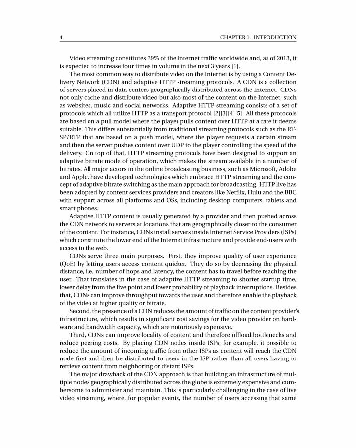
Video streaming constitutes 29% of the Internet traffic worldwide and, as of 2013, itis expected to increase four times in volume in the next 3 years [1].
The most common way to distribute video on the Internet is by using a Content De-livery Network (CDN) and adaptive HTTP streaming protocols. A CDN is a collectionof servers placed in data centers geographically distributed across the Internet. CDNsnot only cache and distribute video but also most of the content on the Internet, suchas websites, music and social networks. Adaptive HTTP streaming consists of a set ofprotocols which all utilize HTTP as a transport protocol [2][3][4][5]. All these protocolsare based on a pull model where the player pulls content over HTTP at a rate it deemssuitable. This differs substantially from traditional streaming protocols such as the RT-SP/RTP that are based on a push model, where the player requests a certain streamand then the server pushes content over UDP to the player controlling the speed of thedelivery. On top of that, HTTP streaming protocols have been designed to support anadaptive bitrate mode of operation, which makes the stream available in a number ofbitrates. All major actors in the online broadcasting business, such as Microsoft, Adobeand Apple, have developed technologies which embrace HTTP streaming and the con-cept of adaptive bitrate switching as the main approach for broadcasting. HTTP live hasbeen adopted by content services providers and creators like Netflix, Hulu and the BBCwith support across all platforms and OSs, including desktop computers, tablets andsmart phones.
Adaptive HTTP content is usually generated by a provider and then pushed acrossthe CDN network to servers at locations that are geographically closer to the consumerof the content. For instance, CDNs install servers inside Internet Service Providers (ISPs)which constitute the lower end of the Internet infrastructure and provide end-users withaccess to the web.
CDNs serve three main purposes. First, they improve quality of user experience(QoE) by letting users access content quicker. They do so by decreasing the physicaldistance, i.e. number of hops and latency, the content has to travel before reaching theuser. That translates in the case of adaptive HTTP streaming to shorter startup time,lower delay from the live point and lower probability of playback interruptions. Besidesthat, CDNs can improve throughput towards the user and therefore enable the playbackof the video at higher quality or bitrate.
Second, the presence of a CDN reduces the amount of traffic on the content provider’sinfrastructure, which results in significant cost savings for the video provider on hard-ware and bandwidth capacity, which are notoriously expensive.
Third, CDNs can improve locality of content and therefore offload bottlenecks andreduce peering costs. By placing CDN nodes inside ISPs, for example, it possible toreduce the amount of incoming traffic from other ISPs as content will reach the CDNnode first and then be distributed to users in the ISP rather than all users having toretrieve content from neighboring or distant ISPs.
The major drawback of the CDN approach is that building an infrastructure of mul-tiple nodes geographically distributed across the globe is extremely expensive and cum-bersome to administer and maintain. This is particularly challenging in the case of livevideo streaming, where, for popular events, the number of users accessing that same
1.1. MOTIVATION 5
infrastructure can be extremely large.An alternative to CDNs is to use peer-to-peer (P2P) as a mean to exploit resources
that are readily available in the network to distribute live streams to a large number ofusers. P2P solutions create an overlay network between the users’ machines and on topof the physical layer of the Internet. In a peer-to-peer system, every peer executes thesame small set of instructions and together all nodes give raise to an emergent behaviorwith specific properties. The main argument in favor of P2P live streaming is that ofscalability, the more users that are running the P2P application the larger the numberof viewers the service is able to sustain. In the P2P model, peers which are part of thesystem retrieve the video content and then forward it to other peers. Since each nodecontributes its own resources to the system, namely upload bandwidth capacity andprocessing power, the capacity of the system usually grows when the number of usersincreases.
1.1 Motivation
Peer-to-Peer overlays have the potential of providing streaming at large scale and with afraction of the cost of CDNs by using resources that are already available at the edge ofthe network, i.e., the user machines, rather than deploying new CDN nodes across theInternet. However, the adoption of peer-to-peer technologies by the industry has beenvery limited. We argue that this is due to two fundamental reasons.
First, classical peer-to-peer live streaming approaches focus on solving the problemof distributing video to a large number of users with the assumption that the source ofthe stream has fixed and limited capacity, e.g. a user machine, trying to provide besteffort quality of user experience (QoE) to users. This is in contradiction with industrialexpectations. Commercial content providers are not willing to compromise on QoE,instead they are willing to sustain the cost of increased capacity at the source of thestream or higher CDN usage to keep the desired level of QoE. As a consequence, weargue that the problem that a peer-to-peer live streaming platform should solve is thatof providing first a well defined level of quality of user experience, such as delay fromthe live point, throughput and continuity of playback, and then try to minimize the loadon the provider’s infrastructure.
Second, current state-of-the-art P2P live streaming (PLS) literature is based on theassumption that video streams are distributed utilizing the RTSP/RTP protocol, whereasthe industry has shifted almost entirely to the pull-based dictated by HTTP streamingprotocols. On top of that, adaptive streaming has been introduced as an integral part ofthe HTTP streaming protocols as means to cope with heterogeneous bandwidth avail-ability and multiple devices with different video rendering capabilities. This shift fromthe push-based RTSP/RTP protocol to the pull-based HTTP-live protocols and the intro-duction in mainstream protocols of adaptive bitrate have rendered many of the classicalassumptions made in the PLS literature obsolete. For the sake of peer-to-peer tech-nology adoption, it is therefore necessary to develop solutions which support adaptiveHTTP streaming.
6 CHAPTER 1. INTRODUCTION
A plethora of solutions has been produced for the problem of scalability of live stream-ing using peer-to-peer in the last years. However, very few of the proposed ideas havebeen implemented in a real environment, even fewer have known adoption by users.Given the commercial context in which this thesis was conducted, our goal is to designan approach which is feasible and then produce a deployed system which can be usedby real viewers. As a consequence of that, we concentrate on testing and evaluation ofour ideas in realistic test-beds and live broadcast events, rather than in simulation orusing mathematical models.
1.2 Contribution
In this thesis, we solve the problem of providing live video streaming to large number ofviewers using peer-to-peer overlays. We do so by assuming that our solution must de-liver a level of quality of user experience which is the same of a CDN while trying to min-imize the load on the content provider’s infrastructure, namely the source of the stream.In addition, our design takes into consideration the realities of the HTTP streaming pro-tocols, such as the pull-based approach and adaptive bitrate switching.
The result of this work is a system which we call SmoothCache and which providesCDN-quality adaptive HTTP live streaming utilizing peer-to-peer algorithms. Smooth-Cache is a peer-assisted solution, it strives to retrieve most of the content from the over-lay but it resorts to existing CDN infrastructure to compensate for deficiencies of thepeer-to-peer delivery. We quantify the system’s quality of user experience and compareit to the one of a CDN-only delivery service using the following metrics: i) cumulativeplayback delay, the time it for the video to start after the user requests it plus the cumula-tive time the playback was interrupted because of lack of data, ii) delivered bitrate, howmany peers could watch a certain bitrate, iii) delay from the playing point, the period oftime between when the content is made available to peers and when it is consumed bythe player.
Considering the aforementioned metrics, in this thesis we show that our system pro-vides performance on the Internet that is equivalent to that of a CDN-only service. Tobe able to make that claim, we conduct a thorough evaluation of the platform on a sub-set of around 22.000 from the around 400.000 installations of our system worldwide.This subset is made by customers who agreed to let us conduct experiments on theirmachines. Our experiments highlight that the system, besides meeting the the CDN-quality constraints, is able to consistently deliver up to 96% savings towards the sourceof the stream in a single bitrate scenario and 94% in a scenario where the stream is madeavailable at different bitrates. In addition to controlled tests on the Internet, we haveconducted a number of pilot deployments in the setting of large enterprise networkswith the same system, albeit tailored to enterprise networks rather than the Internet. Anenterprise network is a large private network which interconnects multiple geographi-cally distributed branches of a company. Links between branches and towards the restof the Internet typically constitute bottlenecks during the broadcast of live events. Re-sults with our SmoothCache system collected during pilot events with thousands of real
1.2. CONTRIBUTION 7
DTL$
Network$Layer$
Framework$
Simula'on*Deployment*
Peer$Sampling$
PLS$Agent$
WAN$heuris<cs$ Private$network$heuris<cs$SmoothCache
Adaptive bitrate HTTP live streaming protocol
Wormhole peer sampling service
NATCracker Network emulation
(Bandwidth)
Mesmerizer
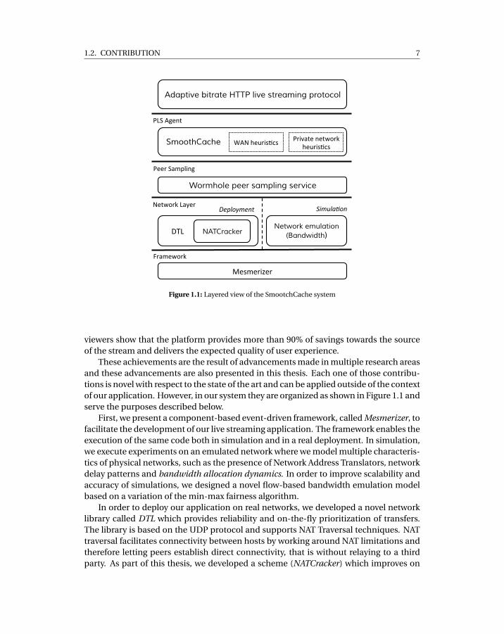
Figure 1.1: Layered view of the SmootchCache system
viewers show that the platform provides more than 90% of savings towards the sourceof the stream and delivers the expected quality of user experience.
These achievements are the result of advancements made in multiple research areasand these advancements are also presented in this thesis. Each one of those contribu-tions is novel with respect to the state of the art and can be applied outside of the contextof our application. However, in our system they are organized as shown in Figure 1.1 andserve the purposes described below.
First, we present a component-based event-driven framework, called Mesmerizer, tofacilitate the development of our live streaming application. The framework enables theexecution of the same code both in simulation and in a real deployment. In simulation,we execute experiments on an emulated network where we model multiple characteris-tics of physical networks, such as the presence of Network Address Translators, networkdelay patterns and bandwidth allocation dynamics. In order to improve scalability andaccuracy of simulations, we designed a novel flow-based bandwidth emulation modelbased on a variation of the min-max fairness algorithm.
In order to deploy our application on real networks, we developed a novel networklibrary called DTL which provides reliability and on-the-fly prioritization of transfers.The library is based on the UDP protocol and supports NAT Traversal techniques. NATtraversal facilitates connectivity between hosts by working around NAT limitations andtherefore letting peers establish direct connectivity, that is without relaying to a thirdparty. As part of this thesis, we developed a scheme (NATCracker) which improves on
8 CHAPTER 1. INTRODUCTION
the state of the art of NAT Traversal techniques resulting in higher probability of directconnectivity between peers on the Internet.
Because of the presence of NATs in the network, discovery of new peers and collec-tion of statistics on the overlay through peer sampling is problematic. Therefore we cre-ated a peer sampling service, the Wormhole peer sampling service, which is NAT-resilientand provides with the same overhead as similar protocols based on gossip one order ofmagnitude fresher samples.
Information provided by the peer sampling service is then used to build our deliveryoverlay. In order to provide the same QoE as CDNs, while achieving savings towards thesource of the stream, we implemented a system called SmoothCache which providesa distributed caching abstraction on top of the peer-to-peer overlay. The distributedcache makes sure that fragments are always delivered on-time to the player by eitherretrieving the data from the overlay if the data is present, or, if the content can’t be re-trieved quickly enough from the P2P network, SmoothCache retrieves it directly fromthe source of the stream to maintain the expected QoE. That said, in order to providesavings, we make sure to fill up the local cache of the peers ahead of playback. Wedo this by implementing prefetching heuristics and by constructing a self-organizingoverlay network that takes into account many factors such as upload bandwidth capac-ity, connectivity constraints, performance history, prefetching point and the currentlywatched bitrate, all of which work together to maximize flow of fragments in the net-work.
Here we summarize each contribution of this thesis separately and state its noveltyaspects:
• Development and emulation framework. We define a set of the best practices inPeer-To-Peer(P2P) application development and combine them in a middlewareplatform called Mesmerizer. That is a component-based event-driven frameworkfor P2P application development, which can be used to execute multiple instancesof the same application in a strictly controlled manner over an emulated networklayer for simulation/testing, or a single application in a concurrent environmentfor deployment purpose. We highlight modeling aspects that are of critical im-portance for designing and testing P2P applications, such as the emulation ofNetwork Address Translation behavior and bandwidth dynamics. We present thiswork in Chapter 3.
• Simulation of bandwidth dynamics. When evaluating Peer-to-Peer live stream-ing systems by means of simulation, it is of vital importance to correctly modelhow the underlying network manages the bandwidth capacity of peers when ex-changing large amount of data. For this reason, we propose a scalable and ac-curate flow-level network simulation model based on an evolution of the classi-cal progressive filling algorithm which employs the max-min fairness algorithm.Our experiments show that, in terms of scalability, our bandwidth allocation algo-rithm outperforms existing models when simulating large-scale structured over-lay networks. Whereas, in terms of accuracy, we show that allocation dynamics
1.2. CONTRIBUTION 9
of the proposed solution follow those of packet-level simulators. We describe ourmodel in chapter 4.
• Transport. We developed a reliable transport library for peer-to-peer applicationswhich provides variable and on-the-fly transfer prioritization. For portability, thelibrary is developed in Java on top of UDP. It implements intra- and inter-protocolprioritization by combining two state of the art congestion control algorithms:LEDBAT and MulTCP. The library supports a range of priority levels, from less-than-best-effort priority up to high. The prioritization level can be configured atruntime by the over-lying application using a single input parameter. Supportfor on-the-fly priority variation enables applications to tune transfers in order toachieve the desired level of QoS. Transitions between different prioritization lev-els happen without disruptions in the flow of data and without the need for con-nection re-establishments, which usually involve time consuming NAT Traversaland peering authentication procedures. We describe the details of our networklibrary in Chapter 6.
• NAT Traversal. We improve on the state of the art on Network Address Transla-tion (NAT) traversal by providing a deeper dissection of NAT behaviors resultingin 27 different NAT types. Given the more elaborate set of behaviors, it is incorrectto reason about traversing a single NAT, instead combinations must be consid-ered. Therefore, we provide a comprehensive study which states, for every possi-ble combination, whether direct connectivity with no relay is feasible. Our novelNAT Traversal framework is presented in Chapter 5.
• Peer Sampling. We present a novel peer sampling service called wormhole-basedpeer sampling service (WPSS) which executes short random walks over a stabletopology. WPSS improves on the state of the art by decreasing the number ofconnections established per time unit by one order of magnitude while provid-ing the same level of freshness for samples. We achieve this without sacrificingthe desirable properties of a PSS for the Internet, such as robustness to churn andNAT-friendliness. Our work on peer sampling can be found in Chapter 7.
• Live Streaming. We designed and developed a distributed cache for adaptiveHTTP live streaming content based on peer-to-peer (P2P) overlays. The contribu-tion of this work is twofold. From a systems perspective, it supports live stream-ing protocols based on HTTP as a transport and the concept of adaptive bitrateswitching. From an algorithmic perspective, the system describes a novel set ofoverlay construction and prefetching techniques that realize: i ) substantial sav-ings in terms of the bandwidth load on the source of the stream, and ii ) CDN-quality user experience. We describe the first iteration of our live streaming plat-form, called SmoothCache 1.0, in Chapter 8, where we show that savings towardsthe source of the stream can be obtained, in the context of adaptive HTTP livestreaming, using peer-to-peer overlays. The next iteration of our system, whichwe call SmoothCache 2.0, is described in Chapter 9. There we present the novel
10 CHAPTER 1. INTRODUCTION
set of heuristics which allows to achieve CDN-quality adaptive HTTP live stream-ing and a thorough evaluation on thousands of consumer machines. Chapter 10presents the application of our system to the scenario of large private networks. Inthat chapter, we outline the changes we implemented in SmoothCache to adaptour algorithms to the private network setting and show initial results with livebroadcasts with thousands of real viewers.
1.3 Publications
We here provide a list of publications which have been published as part of this thesis:
• Roberto Roverso, Sameh El-Ansary, Alexandros Gkogkas, and Seif Haridi. Mesmer-izer: a effective tool for a complete peer-to-peer software development life-cycle. InProceedings of the 4th International ACM/ICST Conference on Simulation Toolsand Techniques [6]. SIMUTools 2011, Brussels, Belgium, 2011
• Alexandros Gkogkas, Roberto Roverso, and Seif Haridi. Accurate and efficient sim-ulation of bandwidth dynamics for peer-to-peer overlay networks. In Proceedingsof the 5th International ICST Conference on Performance Evaluation Methodolo-gies and Tools [7]. VALUETOOLS 2011, Brussels, Belgium, 2011
• Roberto Roverso, Sameh El-Ansary, and Seif Haridi. NATCracker: NAT Combina-tions Matter. In Proceedings of 18th International Conference on Computer Com-munications and Networks 2009 [8]. ICCCN 2009, San Francisco, CA, USA, 2009
• Riccardo Reale, Roberto Roverso, Sameh El-Ansary, and Seif Haridi. DTL: dynamictransport library for peer-to-peer applications. In Proceedings of the 12th Interna-tional Conference on Distributed Computing and Networking 2012 [9]. ICDCN2012, Hong Kong, China, 2012
• Roberto Roverso, Jim Dowling, and Mark Jelasity. Through the wormhole: Lowcost, fresh peer sampling for the internet. In Peer-to-Peer Computing (P2P), 2013IEEE 13th International Conference on [10]. P2P 2013, Trento, Italy, 2013
• Roberto Roverso, Sameh El-Ansary, and Seif Haridi. Smoothcache: HTTP-live stream-ing goes peer-to-peer. In IFIP International Conferences on Networking 2012, vol-ume 7290 of Lecture Notes in Computer Science [11]. NETWORKING 2013, Prague,Czech Republic, 2013
• Roberto Roverso, Sameh El-Ansary, and Seif Haridi. Peer2view: A peer-to-peerHTTP-live streaming platform. In Peer-to-Peer Computing (P2P), 2012 IEEE 12thInternational Conference on [12]. P2P 2012, Tarragona, Spain, 2012
• Roberto Roverso, Sameh El-Ansary, and Seif Haridi. SmoothCache 2.0: the HTTP-Live peer-to-peer CDN. In Peerialism White Papers, Stockholm, Sweden 2013

1.3. PUBLICATIONS 11
• Roberto Roverso, Sameh El-Ansary, and Mikael Hoeqvist. On HTTP live streamingin large enterprises. In Proceedings of the ACM conference on applications, tech-nologies, architectures, and protocols for computer communication [13]. SIG-COMM 2013, Hong Kong, China, 2013
List of publications of the same author but not related to this work
• Roberto Roverso, Amgad Naiem, Mohammed Reda, Mohammed El-Beltagy, SamehEl-Ansary, Nils Franzen, and Seif Haridi. On The Feasibility Of Centrally-CoordinatedPeer-To-Peer Live Streaming. In Proceedings of IEEE Consumer Communicationsand Networking Conference 2011 [14]. CCNC 2011, Las Vegas, NV, USA, 2011
• Roberto Roverso, Amgad Naiem, Mohammed El-Beltagy, Sameh El-Ansary, andSeif Haridi. A GPU-enabled solver for time-constrained linear sum assignmentproblems. In Informatics and Systems, 2010 The 7th International Conferenceon [15]. INFOS 2011, Cairo, Egypt, 2010.
• Roberto Roverso, Mohammed Al-Aggan, Amgad Naiem, Andreas Dahlstrom, SamehEl-Ansary, Mohammed El-Beltagy, and Seif Haridi. MyP2PWorld: Highly Repro-ducible Application-Level Emulation of P2P Systems. In Proceedings of the 2008Second IEEE International Conference on Self-Adaptive and Self-Organizing Sys-tems Workshops [16]. SASO Workshops 2008, Venice, Italy, 2008.
• Roberto Roverso, Cosmin Arad, Ali Ghodsi, and Seif Haridi. DKS: Distributed K-Ary System a Middleware for Building Large Scale Dynamic Distributed Applica-tions, Book Chapter [17]. In Making Grids Work 2007, Springer US, 2007.

CH
AP
TE
R
2BACKGROUND
In this chapter, we present the main concepts that are necessary to understand the re-search explained in the rest of the thesis.
We start by describing standard practices for the distribution of live content overthe Internet to large audiences in Section 2.1. We then define the challenges of usingpeer-to-peer networks for Internet live streaming in Section 2.1. After that, we providean extensive description of state-of-the-art techniques to overcome those challenges.The techniques are classified in two main areas: construction/management of overlays,presented in Section 2.2.1, and data dissemination, discussed in Section 2.2.2. In Sec-tion 2.2.3, we highlight methods to leverage infrastructure resources to achieve a qualityof user experience in peer-to-peer live streaming that compares to that of client-serversolutions.
Besides live streaming, in this chapter we also discuss other topics that are relevantto the design and implementation of peer-to-peer content delivery systems. In Sec-tion 2.3, we delve into details of peer connectivity in the presence of Network AddressTranslators (NATs). In Section 2.4, we introduce peer sampling algorithms that are usedto provide inpuy for peer-to-peer overlay construction in P2P live streaming and that arealso resilient to NATs. In Section 2.5, we describe transport protocols for peer-to-peercontent distribution applications which are employed to transfer data between peersonce the overlay network is in place. We conclude the background chapter with Sec-tion 2.6 that summarizes a set of best practices that we found useful for developmentand evaluation of peer-to-peer applications.
13
14 CHAPTER 2. BACKGROUND
2.1 Live Streaming
In live streaming, content is created and broadcasted in real-time. The strongest con-straint on the delivery of the stream is that the stream must be received within a smalldelay from the time it is generated by the content provider. Furthermore, users in thesame geographical region should not experience significant differences in their play-back point. These requirements tie directly into the meaning of live broadcasting.
Live streaming is usually implemented using stateful push-based protocols, such asRTP/RTSP[18] and RDT[19], where a player software installed in the viewer’s machineestablishes and manages media sessions by issuing commands to the streaming server,e.g. play, stop and pause. The data is delivered to the player by having the server pushthe content fragments at at the rate it deems suitable to the player. At the transport level,data is delivered over UDP, while TCP is used for control messages.
Recently, the industry has introduced a new technology for live streaming, calledAdaptive HTTP streaming. Adaptive HTTP streaming consists of a set of protocols whichall utilize HTTP as transport [2][3][4][5]. HTTP-live streaming protocols are based on apull-based model, where it is the player which requests content over HTTP at the paceit deems suitable. On top of that, HTTP-live protocols have been designed to support anadaptive bitrate mode of operation, which provides the stream at a number of bitrates.This shift to HTTP has been driven by a number of advantages such as the following: i )Routers and firewalls are more permissive to HTTP traffic compared to the RTSP/RTPi i ) HTTP caching for real-time generated media is straight-forward like any traditionalweb-content i i i ) the Content Distribution Networks (CDNs) business is much cheaperwhen dealing with HTTP downloads [4].
In HTTP streaming, the stream is split into a number of small HTTP packets, i.e. frag-ments, and the streaming server appears to the player as a standard HTTP server. Whena player first contacts the streaming server, it is presented with a descriptor file, calledManifest, which outlines the characteristics of the stream. It contains the stream’s frag-ments path on the HTTP server and the quality of bitrates available for the stream. Afterreading the manifest, the player starts to request fragments from the server. The burdenof keeping the timeliness of the live stream is totally upon the player, while the server isstateless and merely serves fragments like any other HTTP server after encoding themin the format advertised in the manifest. That means that the player implements a num-ber of heuristics that determine at which pace fragments should be downloaded and atwhich bitrate [20][21][22]. In general, the choice of bitrate to request is dictated by theavailable bandwidth. That is, when the user has more available bandwidth, the playerrequests a higher quality stream and when the host has lower bandwidth available it re-quests a lower quality stream. Other factors that can influence the choice of bandwidthare, for example, the computational power of the machine the player is running on orhow fast the machine’s graphic card can render video content. Different HTTP stream-ing player implementations use different heuristics and behave in different ways. Thus,it is not possible to predict a player’s behavior. In fact, it is common to observe changesin behaviors even in different versions of the same player implementation.
2.2. PEER-TO-PEER LIVE STREAMING 15
2.2 Peer-to-peer Live Streaming
Live streaming on overlays is inherently difficult due to the fact that participating nodesare not reliable and they might become unavailable at any time because of temporarycongestion, connectivity issues or simply because of users leaving the system. The pro-cess of continuous joining and leaving of nodes is called churn. Much attention in thedesign of P2P algorithms for live streaming is therefore dedicated to trying to maintain acertain level of performance in the delivery of the stream while coping with churn. Datacollected from the deployment of the peer-to-peer live streaming platform PPLive [23]show that a steady amount of churn is expected when broadcasting linear TV channels.On top of that, flashcrowds and massive failure scenarios are also observed, that is thesudden join and the sudden departure of a large number of nodes, respectively.
Another source of complexity in the design of peer-to-peer systems is network-levelcongestion. Congestion stems from the overloading of physical network’s resources,caused by excessive user-generated traffic in the network, which causes the formationof bottlenecks along routing paths between peers on the overlay. The effects of networkcongestion on P2P live streaming are: diminished throughout, longer transmission de-lay, packet loss and blocking of new connections. Although it is believed that most of thetime bottlenecks form at the last mile segment in the Internet infrastructure, i.e. at resi-dential gateways, congestion can be experienced at different levels in the network. Onereason for that is that ISPs and ASs dimension their internal network and border linksconsidering the average usage scenario, rather than the peak. That means that conges-tion happens every time more users than expected access their ISP network. This canhappen, for example, during the streaming of live events of high interest.
In classical peer-to-peer live streaming approaches, the delay from the time the con-tent is generated by the provider to the time it is delivered to the player may vary for eachpeer. This is because the data has to traverse multiple hops before becoming availablefor playback at a peer. The number of hops depends on how the overlay is constructedand how quickly the data is transferred at each hop. Depending on the capacity at thesource of the stream, the delay might be very long, on the order of many seconds oreven minutes. In this thesis however, we work under the assumption that there must bea target delay value and the system must strive to keep this value constant and the samefor all peers. Given that peer-to-peer delivery is strongly influenced by churn and con-gestion, the target delay usually cannot be guaranteed with peer-to-peer delivery alone.For that reason, a new breed of hybrid systems which uses infrastructure resources tocompensate for the limitations of P2P delivery was recently introduced. In the followingsections, we are going to describe general peer-to-peer overlay techniques which applyboth to classical P2P live streaming and hybrid infrastructure/P2P systems. We will thenhighlight the infrastructural characteristics of the latter in Section 2.2.3.
Peer-to-peer live approaches differ mainly on two levels: overlay construction anddata dissemination. Overlay construction is the set of heuristics a live streaming sys-tem uses to create the set of connections between peers which then would be used totransport control messages and the stream data. The data is usually logically split intofixed-size chunks which are transferred between peers according to a certain data dis-
16 CHAPTER 2. BACKGROUND
Figure 2.1: Representation of a tree-based over-lay structure
!"!
! #! "
! $
!%
!&&!
! &'!
!(
!&'!
!&!
!)!
!#!
!$!
!*! !
+
,!
Figure 2.2: Representation of a multi-tree-based overlay structure
semination strategy.
2.2.1 Overlay ConstructionThere exists three main classes of overlay construction techniques that are commonlyused for live streaming: tree-based, mesh-based and hybrid.
Tree-based
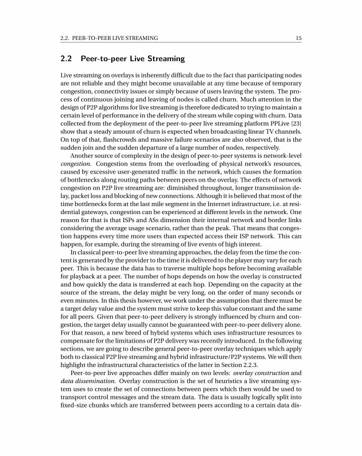
Tree-based overlay construction techniques aim to have peers self-organize in a tree-like structure, like the one presented in Figure 2.1, where the source of the content ispositioned at the root of the tree. The content is disseminated from the root of the treeto the other peers by letting peers receive the video from their parents and then forwardit to their children. Famous examples of tree-based systems are Overcast [24], Climber[25] and ZigZag [26]. The main advantage of a tree-based overlay is that the distributiondelay for each peer is proportional to the number of hops from the source and the delaycorresponds to the sum of the delays traversing the tree.
In tree-based systems, a peer has one or more parents which provide it with chunksof data and a set of children which it is forwarding the received chunks to. The num-ber of children which a parent can provide for is proportional to the bandwidth uploadcapacity of a peer. That is typically a parent has a number of children which equalsto its upload capacity divided by the bitrate that peers are watching. It is widely ac-cepted [27][14][28] that the most efficient strategy to place peers in a overlay tree is bysorting them according to the number of children they can afford, that is their uploadbandwidth. Peers with highest upload bandwidth capacity are usually placed near thethe source of the stream and the others in subsequent rows depending on their uploadcapacity, in decreasing order. This makes sure that the number of rows in the tree is keptto a minimum and therefore also the amount of time after which the peers receive thecontent is also minimized.
Tree-based systems may rely on a single tree or on multiple tree structure. In a sin-gle tree structure, the leaves of the tree do not contribute to the delivery of the stream,
2.2. PEER-TO-PEER LIVE STREAMING 17
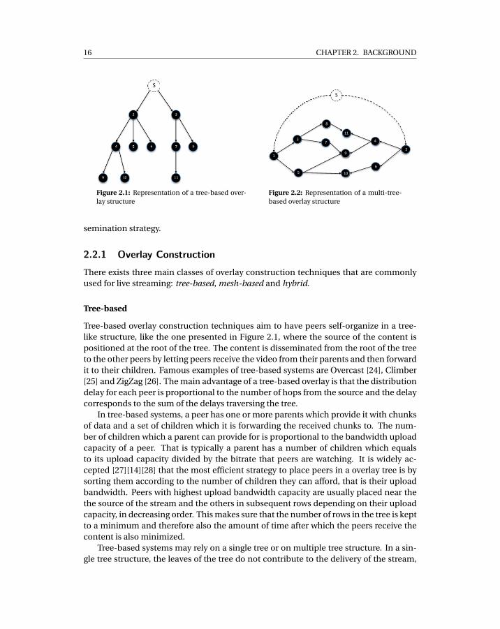
since they have no children. In a multi-tree configuration instead, the content serversplits the stream in multiple sub-streams which are then disseminated over separatetree-shaped overlays. As a consequence, a peer might be parent for a sub-stream butonly a child for another. Solutions using this approach are, for instance, SplitStream[29] and Orchard [30]. A study on a widely deployed system, i.e. GridMedia [31], hasshown that using multi-tree based systems leads to better performance than single-treeapproaches and to near-optimal bandwidth utilization. Figure 2.2 shows a multi-treeoverlay network structure. In the example, two sub-streams are broadcasted from thesource of the stream along two trees, starting at peer 2 and 1.
The main disadvantage of tree-based approaches is that they are not strongly re-silient to churn. In fact, when a peer abruptly leaves the overlay, all of its descendantsget disconnected also and need to find another ancestor. On top of that, parts of theoverlay can become partitioned from the rest of the overlay. Even if solutions have beensuggested to alleviate these issues, such as the use of structured networks for peer place-ment [29], it is widely accepted that tree-based overlays are inferior to mesh-based ap-proaches in presence of churn [32].
The two broad classes of algorithms used to construct tree-based overlays are cen-tralized and decentralized algorithms.
Centralized Construction. In centralized tree construction approaches, a centralcoordinator instruct peers about which parent they should receive the stream from. Thepeers periodically report performance metrics to the coordinator. The central coordi-nator then keeps an overview of the system which includes the configuration of the treeat a certain point in time. Using this information, the central server makes decisionsabout where to place new peers in the overlay topology.
The principal drawback of this approach is that the coordinator constitutes a singlepoint of failure in the system. If the coordinator fails, new peers cannot join the overlay.Also, peers that are already in the system cannot replace failed parents. In addition tothat, the central coordinator is the main performance bottleneck in centralized systems.It must cope with both significant number of peers joining in a short period of time, i.e.flash crowds, and large amounts of peers leaving the system abruptly, i.e. massive fail-ures. Both phenomena are very common in live streaming [23]. During flash crowds andmassive failures periods, the coordinator needs to handle high network traffic comingfrom peers but also it must re-evaluate the view of the overlay very frequently in orderto be able to instruct new and old peers on which parents to use.
Examples of systems using centralized coordination are Peer2View [33] and Coop-net [34]. Central coordination has also been used for classical content distribution inAntfarm [35].
Distributed Construction. A number of distributed algorithms have been designedto construct and maintain a tree-based live streaming overlay. In this approach, peersnegotiate by means of gossiping their placement in the tree mainly using their uploadbandwidth as a metric. Examples of systems using decentralized tree construction are:SplitStream [29], Orchard [30] and ChunkySpread [36].
18 CHAPTER 2. BACKGROUND
!"
! #! "
! $
!%%!
! %&!
!'
!%&!
!%
!#!
!$!
!(! !
)
*!
+!
!,! !
%(!
!%,!
Figure 2.3: Representation of a mesh-based overlay structure
Mesh-based
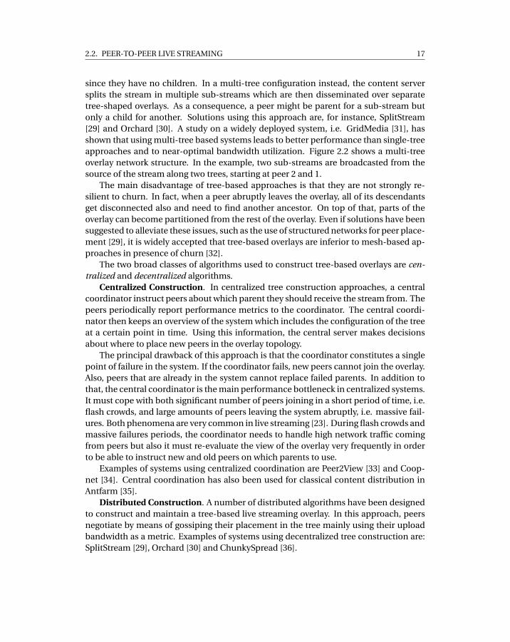
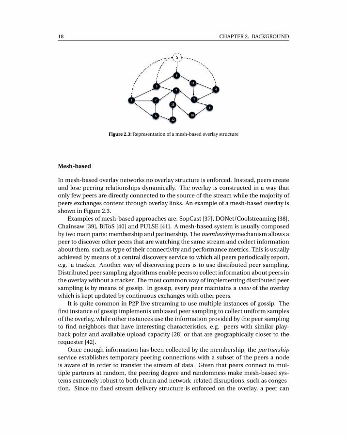
In mesh-based overlay networks no overlay structure is enforced. Instead, peers createand lose peering relationships dynamically. The overlay is constructed in a way thatonly few peers are directly connected to the source of the stream while the majority ofpeers exchanges content through overlay links. An example of a mesh-based overlay isshown in Figure 2.3.
Examples of mesh-based approaches are: SopCast [37], DONet/Coolstreaming [38],Chainsaw [39], BiToS [40] and PULSE [41]. A mesh-based system is usually composedby two main parts: membership and partnership. The membership mechanism allows apeer to discover other peers that are watching the same stream and collect informationabout them, such as type of their connectivity and performance metrics. This is usuallyachieved by means of a central discovery service to which all peers periodically report,e.g. a tracker. Another way of discovering peers is to use distributed peer sampling.Distributed peer sampling algorithms enable peers to collect information about peers inthe overlay without a tracker. The most common way of implementing distributed peersampling is by means of gossip. In gossip, every peer maintains a view of the overlaywhich is kept updated by continuous exchanges with other peers.
It is quite common in P2P live streaming to use multiple instances of gossip. Thefirst instance of gossip implements unbiased peer sampling to collect uniform samplesof the overlay, while other instances use the information provided by the peer samplingto find neighbors that have interesting characteristics, e.g. peers with similar play-back point and available upload capacity [28] or that are geographically closer to therequester [42].
Once enough information has been collected by the membership, the partnershipservice establishes temporary peering connections with a subset of the peers a nodeis aware of in order to transfer the stream of data. Given that peers connect to mul-tiple partners at random, the peering degree and randomness make mesh-based sys-tems extremely robust to both churn and network-related disruptions, such as conges-tion. Since no fixed stream delivery structure is enforced on the overlay, a peer can
2.2. PEER-TO-PEER LIVE STREAMING 19
quickly switch between different provider peers if a failure occurs or of the the neces-sary streaming rate cannot be sustained.
A partnership between two peers is commonly established according to the follow-ing metrics:
• The load on the peer and resource availability at both ends. Possible load metricsinclude: available upload and download bandwidth capacity and CPU/memoryusage.
• Network Connectivity. The potential quality of the link between the two peers interms of delay, network proximity and firewall/NAT configurations, as in [8].
• Content Availability. The available data chunks, at both ends, i.e. the parts of thestream which have been already downloaded and are available locally at a peer.
As for drawbacks, control traffic generated by the mesh-based partnership service isusually significant given that peers need to frequently exchange status information fordeciding which are the best peers to download chunks from. On top of that, in mesh-based systems, a larger number of connections are maintained than for tree-based sys-tems. A high number of partners gives more flexibility when requesting content so thatpeers may have more choice to quickly change from one partner to another if compli-cations arise during the delivery.
Another drawback of the mesh-based approach is sub-optimal bandwidth utiliza-tion of provider peers since every data chunk is treated as a separate delivery unit, whileper-chunk distribution paths and delivery times are not predictable and highly variable.
Hybrid Overlay Construction Approaches
A tree-based approach can be combined with a mesh-based one to obtain better band-width utilization. mTreebone[43] elects a subset of nodes in the system as stable anduses them to form a tree structure. The content is broadcasted from the source nodealong the tree structure. A second mesh overlay is then built comprising both the peersin the tree and the rest of the peers in the system. For content delivery, the peers relyon the few elected stable nodes but default to the auxiliary mesh nodes in case of a sta-ble node failure. The drawback of this approach is that a few stable peers might becomecongested while the others are not contributing with their upload bandwidth. Thus, thissolution clearly ignores the aspect of efficient bandwidth utilization.
CliqueStream [44] presents an alternative approach where clusters of peers are cre-ated using both delay and locality metrics. One or more peers are then elected in eachcluster to form a tree-like structure to interconnect the clusters. Both in PRIME [45]and NewCoolsteaming [46], peers establish a semi-stable parent-to-child relationshipto combine the best of push and pull mesh approach. Typically a child subscribes toa certain stream of chunks from the parent and the parent pushes data to the child assoon as it becomes available. It has been shown that this hybrid approach can achievenear-optimal streaming rates [47] but, in this case as well, no consideration has beengiven to efficient bandwidth utilization.
20 CHAPTER 2. BACKGROUND
2.2.2 Data Dissemination
In classical peer-to-peer live streaming systems, peers typically have full control of theplayer software. The player is very resilient and can afford temporary starvation, inwhich case it just stops rendering the video, and loss of consecutive video fragments,then it merely skips the missing fragments. To alleviate the effect of temporary disrup-tions on data delivery, caused by churn, connectivity issues and congestion, p2p sys-tems introduce a buffer between the overlay and the player. The presence of the bufferincreases the probability of downloading video fragments in time before they are duefor playback. Since the buffer introduces a delay from the point the data is received bythe peer to the time it is provided to the player, it is usually desirable to keep the size ofthe buffer small.
Once an overlay is in place, peers can start exchanging data to fill the buffer usingmultiple strategies. The most common are push, pull and push-pull. Push-based dis-semination is typical of tree-based systems. Parent peers receive data chunks and for-ward them to the children as fast as possible. This guarantees high throughput betweenpeers and in general maximizes bandwidth utilization on the overlay. Unfortunately,due to churn, peers may be forced to switch frequently between parents and, therefore,waste upload capacity of parents in the process.
The pull-based technique is instead typical of mesh-based systems. In pull-basedsystems, partners on the overlay exchange bitmaps which indicate which video chunksthey have downloaded up to the moment of the exchange. The pull method is veryresilient to churn because content chunks are only requested from partners which haverecently advertised said chunks and therefore have a high probability of being alive.On the other hand, there is no guarantee that a peer will receive enough requests forfragments from its partners and thus utilize its full upload capacity.
In pull-based methods, a scheduler on each peer is given the task of requesting con-tent chunks as the playback progresses based on availability at its partners. Since eachchunk may be requested individually and from different partners, chunks may be de-livered over different paths to a peer and arrive out of order. Consequently, the peerre-orders chunks before delivering them to the player. In addition, it may happen thata data chunk can not be downloaded by a node because it is not available at its part-ners (content bottleneck) or the upload bandwidth of it partners is not insufficient totransfer the chunk in time (bandwidth bottleneck) [48]. For decreasing the probabil-ity of failing to download a chunk in time, it is common to employ different retrievalstrategies according to the timeline of chunks. GradienTv [28], for instance, normallyrequests chunks from peers that have a similar upload bandwidth capacity. However,for chunks that are due for playback soon, and have not been dowloaded yet, it issuesrequests to peers with higher upload capacity. This increases the probability of down-loading missing fragments on time. In Bittorrent-based live streaming platforms, suchas Pilecast [49], peers use a combination of the rarest-first and greedy policies [50] to de-cide which fragments to pull from neighbors. Peers employ the greedy policy to down-load chunks which are due for playback soon, that is in the next 15 seconds of playback.When all of those fragments have been retrieved, peers switch to the rarest-first policy in
2.2. PEER-TO-PEER LIVE STREAMING 21
order to download future fragments, that is more than 15 seconds ahead of the playbackpoint. Finally, some systems leverage structured overlay networks, such as DistributedHash Tables, to improve availability of chunks. In HyDeA [51], a custom DHT is usedto find and retrieve chunks which, again, were not retrieved quickly enough from theunstructured mesh-based network.
There exists also systems which implement a combination of the push and pullmethods to overcome the limitations of both pull, that is content and bandwidth bottle-necks, and push, that is limited resiliency to churn. In push-pull based systems, whena new peer joins the system, it pulls data from nodes that are already in the overlay.After a period of observation and learning about possible candidates, a peer choosesone or multiple parents from its partners which then start to push data to it. If someof the chunks cannot be downloaded in time, a peer resorts again to pull from theirpartners. Examples of systems implementing push-pull are Gridmedia[52], NewCool-Streaming [46], CliqueStream [44], and mTreebone [43].
2.2.3 Infrastructure-aided P2P Live StreamingWe have, up until now, mentioned systems that rely exclusively on peer-to-peer re-sources to distribute live content over the Internet. Here instead, we survey a classof hybrid live streaming systems which use both infrastructure services, such as cloudservers or CDNs, and peer-contributed resources to meet a quality of user experiencefor viewers which compares to that of client-server solutions. In this type of systems,peers leverage the peer-to-peer network to retrieve the majority of content chunks, butthey resort to central infrastructure to compensate for deficiencies of the peer-to-peerdelivery, such as node-to-node congestion and churn.
We classify infrastructure-aided P2P live streaming systems in two categories: cloud-assisted and peer-assisted. The former category includes systems which build their ownad-hoc infrastructure to aid the peer-to-peer overlay, while systems in the latter cate-gory use existing infrastructure such as Content Delivery Networks for the same pur-pose. While the approaches may differ, both categories of systems share the same goalof enforcing a specific target quality of user experience for viewers, in terms of delay anddelivered bitrate, by using the least amount of infrastructure resources possible.
Cloud-assisted
The main idea behind cloud-assisted approaches is to leverage cloud resources, that isdynamic allocation of helper servers, to build an ad-hoc infrastructure to support thepeer-to-peer overlay and achieve the target QoE. In cloud-assisted systems, a coordi-nator dynamically allocates cloud server instances with a specific amount of resources,that is computation and bandwidth capacity, to serve the peer-to-peer network accord-ing to the current state of the overlay. The coordinator continuously receives feedbackfrom all peers and periodically estimates the number of cloud servers needed to en-force the target QoE. This target is typically expressed as a bound on the playback delayfrom the live point for all peers in the system. The metrics used as input for the co-
22 CHAPTER 2. BACKGROUND
ordinator’s decision are: the bitrate of the video being watched, the total number ofpeers, the bandwidth capacity of helper servers and the characteristics of peers, suchas upload bandwidth capacity and churn rate. Since cloud servers are allocated andremoved dynamically, cloud-assisted solutions can limit the amount of infrastructureresources, and therefore cost, to a minimum. On the other hand, cloud-assisted solu-tions are cumbersome to deploy in existing commercial live streaming systems that relyon CDN services. They in fact require a complete re-engineering of the server-side ofthe system to allow feedback between the peer-to-peer overlay and the coordinator. Be-sides that, a completely new management layer for cloud resources must be developedand deployed for the coordinator to enforce its decisions.
The most popular example of cloud-assisted live streaming system is LiveSky [53].CALMS [54], Clive [55] and Angelcast [56] are other instances of the same approach. Incontrast to standard cloud-assisted solutions, PACDN [57] proposes an approach wherethe infrastructure is made of pre-existing edge servers rather than dynamically allocatedcloud nodes. In PACDN, edge servers form their own centrally-coordinated tree-basedoverlay network to make sure content is distributed efficiently from the streaming serverto all edge nodes. Similarly to cloud-assisted approaches, edge nodes are activated orde-activated dynamically by a coordinator according to the state of the user-contributedpeer-to-peer network.
Peer-Assisted
In contrast to cloud-assisted approaches, peer-assisted content delivery has the goal ofmaking use of existing Content Delivery Networks infrastructure to help the peer-to-peer delivery. This, without the need for integration.
From an operational point of view, it means that peers in the system strive to down-load most of the content from the user-contributed peer-to-peer network but they re-sort to the CDN in case video chunks cannot be retrieved in time from the overlay. Theunderlying assumption in this case is that the CDN has enough capacity to complementthe peer-to-peer delivery at all times.
CDNs are inherently elastic, they implement mechanisms to automatically scale upor down resources according to the experienced load. This is motivated by the fact thatit is very common for a CDN to experience dramatically varying demand for video con-tent on the Internet depending on factors such as increased/decreased popularity andtime of the day. Peer-assisted hybrid approaches rely on CDN elasticity to make surethat there is always enough bandwidth at the server side for peers to use in order tocompensate for the deficiencies of the peer-to-peer overlay. The clear advantage in thiscase is that peer-assisted systems do not need coordination with the central infrastruc-ture but rather extend the capacity of CDNs without the need of integration against theserver side of the system. This makes deployment much easier than cloud-assisted ap-proaches.
Because of its inherent benefits, the peer-assisted approach has recently gained mo-mentum in the video distribution industry with companies developing their own peer-assisted content delivery software, such as Akamai’s NetSession [58], or integrating peer-
2.3. PEER-TO-PEER CONNECTIVITY 23
to-peer in their existing distribution frameworks, as in the case of the Adobe’s Flashframework [59]. Both NetSession and the Flash framework also support adaptive bi-trate HTTP streaming but they are mostly used for Video-on-Demand (VoD) [60][58]rather than live streaming. Note that, in industrial context, the concept of peer-assistedstreaming has a slightly different meaning from the one presented in academic litera-ture. In industrial peer-assisted systems, the CDN can afford the load of serving all usersin the system by scaling up and down resources as needed. The peer-to-peer delivery isthen leveraged as a method to drive down the amount of bandwidth consumed by VoDviewers but it is never expected to carry most of the delivery, as it does in all academicwork.
In academia, the use of peer-assisted delivery has also been limited to video-on-demand streaming. From a theoretical point of view, efforts have been directed at un-derstanding in general, and without considering the details of streaming protocols, whatare the best prefetch policies for peers to download content ahead of the playback dead-line such that the load on the source of the stream is minimized [61][62]. Recent work,by Maygh [63], instead proposed a practical solution to enable peer-assisted distribu-tion of adaptive bitrate HTTP streaming of VoD content using plugin-less browser-basedtechnologies. Authors show that Maygh can save up to 75% of the load on the CDN inthe considered scenarios.
We have mentioned so far approaches that resort to peer-assisted delivery for videoon demand streaming, and, in most cases, also provide support for adaptive HTTPstreaming. In this thesis instead, we apply the peer-assisted approach to live stream-ing. The result of our efforts is the SmoothCache system, which is the first peer-assistedsolution for the distribution of adaptive bitrate HTTP live streaming over the Inter-net [11][64] and in large private networks [13].
The two different iterations of the SmoothCache system design are presented inChapter 8 and Chapter 9. While we describe the application of the same system to thesetting of large private networks in Chapter 10.
2.3 Peer-to-peer Connectivity
In the Internet, it is common to encounter a large amount of peers behind NetworkAddress Translators (NATs), typically around to 70−80% [8][66]. The presence of NATshinders the functioning of peer-to-peer systems because they prevent direct commu-nication between peers which are behind NATs. Conversely, if a peer can’t connect toother peers because its NAT prevents it doing so, it can’t contribute with its resources tothe system and might also be excluded from the service. Consequently, working aroundNAT connectivity issues is of paramount importance for any peer-to-peer system de-ployed on the Internet. This is particularly true for content delivery systems, such asP2P live streaming platforms, which rely on large availability of user-contributed band-width to provide a good quality of service.
A NAT device allows many hosts to share the same public IP address. Behind theNAT, peers are assigned private addresses. Communication between private and public
24 CHAPTER 2. BACKGROUND
hosts is possible only if the host behind NAT was the initiator of the communication.NAT routing behavior can be summarized as follows: when a private node tries to con-tact a host outside the private network, an entry is created in the NAT device’s registry,called the NAT translation table, with its destination host’s IP and port. The outgoingpackets are then translated to appear from the IP address of the NAT device. That is theIP headers of the outgoing packets are re-written to override the private node’s IP andport with the public ones of the NAT device. When a response packet is generated bythe node outside the private network, the NAT device inspects the source IP and port ofthe packet and tries to match them using the NAT translation table. If a private host isfound which communicated with that source IP and port, the packet is forwarded to theprivate node, otherwise the packet is dropped without any notification to the originator.
In order to overcome NAT limitations, a number of NAT traversal techniques havebeen developed in the last decade. These enable connectivity between pairs of peerswhen one or both of them are behind a NAT. NAT traversal can be carried out both usingthe TCP and UDP protocol, however it is significantly more effective on the latter [67].
The most widely used NAT traversal protocol for UDP is the STUN protocol [68].The STUN protocol details a technique known as simple hole punching which lets pri-vate hosts create NAT entries in their NAT device by sending packets towards a centralSTUN server which is always available. The STUN server receives the packets and com-municates which public IP and port the packets came from to the originator. This in-formation then can be used by other hosts outside the private network to contact theprivate peer using the previously established NAT entry.
NAT boxes implement a number of behaviors which vary from extremely easy totraverse to extremely difficult [69][70][71]. It is typical for the simple hole punchingtechnique to succeed only on around 40% of the cases [8]. When hole punching fails,most peer-to-peer systems resort to relaying though a third-party, which is usually adedicated server. This approach has been standardized in the TURN RFC [72]. STUNand TURN protocols have also been integrated in a single standard, the ICE RFC [73].ICE is the de-facto standard in the industry and many commercial peer-to-peer proto-cols rely on it. Examples of such protocols are WebRTC [74] and the SIP Voice over IPprotocol [75]. That said, relaying of packets, while effective for connectivity betweenpeers behind problematic NATs, is extremely expensive since it consumes large amountof bandwidth at the relay side to receive and forward data. For peer-to-peer systemswhere the content transferred is big, such as live streaming systems, it is not advisableto use relaying.
Besides simple hole punching, a number of other NAT traversal techniques havebeen developed by the research community [76][71]. These techniques try to exploitdetailed knowledge of the NAT device’s behavior to establish connections in presence ofNAT by using a third party facilitator to help coordinating the establishment process.
Besides NAT Traversal, the other approach for peers behind NAT to become reach-able from external hosts is to use application layer protocols such as UPnP [77] andNAT-PMP [78]. These two protocols allow applications to configure static NAT transla-tion entries on NAT devices, such that hosts on the outside of the private network canuse the reserved the static entry’s IP and port to initiate a communication towards the
2.4. PEER SAMPLING 25
host that has configured the entry. Unfortunately these protocols are not enabled bydefault in home routers for security reasons and they are not supported by enterpriseNATs.
Research on NAT traversal has not known significant advancements in the last yearseven though NAT constraints are one of the most relevant issues in peer-to-peer sys-tems, for the simple fact that good connectivity is a precondition for any distributedalgorithm to function correctly.
In this thesis, we present in Chapter 5 an extensive classification of NAT behaviorsand an elaborate method to explicitly determine which NAT traversal technique shouldbe used for each combination of NAT behaviors. We show that our approach results ina connection establishment success rate of 85% without using relaying or applicationlevel protocols such as UPnP and NAT-PMP.
2.4 Peer Sampling
As mentioned earlier, when describing mesh-based peer-to-peer live streaming systems(Section 2.2.1), a peer sampling service (PSS) is a vital component of peer-to-peer livestreaming system because it provides the input to overlay construction algorithms.
A peer sampling service (PSS) provides nodes in an overlay with a uniform randomsample of live nodes from all nodes in the system, where the size of the sample set orview is typically much smaller than the system size. Peer sampling services are widelyused in peer-to-peer systems to discover new peers and collect global statistics aboutthe overlay. Also, a PSS can be used as a building block for other services, such as dis-semination [85], aggregation [86] as well as overlay construction and maintenance [87].
The most common approach to peer sampling is Gossip. In gossip, peers keep afixed-size view of the overlay, then periodically select a node from that view and ex-change a number of items from the view with it. In [88], a classification of Gossip pro-tocols was presented that categorizes algorithms by each of the following three points:node selection, view propagation and view selection. Node selection defines how a peerchooses which nodes to exchange its view with. Examples of strategies include: random(rand strategy) and based on the age of the entry associated with each node in the view.The most common approach is to use the oldest entry (tail strategy). View propagationdetermines if a node only pushes samples to the other node (push strategy) or it also re-ceives a number of samples from the destination peer in response (push-pull strategy).Finally, view selection defines how a node updates its view after receiving samples fromthe another node. It can either replace a number of nodes in its view with the ones re-ceived in the exchange uniformly at random (blind strategy) or replace the oldest in itsview (healer). In case of push-pull view propagation, another possible strategy is replac-ing the nodes sent to the other peer with the ones received in the response (swapper).
Peer sampling services are typically evaluated by estimating the global randomnessof samples, that is the amount of correlation between samples returned by the serviceat different nodes. The common practice for doing that it is to use graph theoreticalmethods on the overlay graph defined by the set of nodes in the system and their views.
26 CHAPTER 2. BACKGROUND
In the overlay topology graph, each peer is a node and there exists an outgoing edgefrom a node a to a node b if peer a contains peer b in its view of the overlay. The goal ofthis analysis is to estimate how similar the overlay topology graph is to a random graph,that, by assuming that entries in each peer view are a random sample of the set of allnodes in the system.
Two graph-theoretic metrics are used to estimate the global randomness of the over-lay graph: the in-degree and the clustering coefficient. The In-degree of a node is thenumber of incoming edges that a node has in the overlay graph and it is a measure ofhow a node is represented in the graph. Intuitively, nodes should not be highly over- orunder-represented in the overlay graph to avoid creating hotspots or bottlenecks in thesystem. On top of that, the in-degree value distribution of all peers should follow a bi-nomial distribution, as it does in random graphs. The clustering coefficient of a node isinstead the number of edges between each of the peer’s neighbors over the total amountof possible edges between them. Low clustering coefficient is desirable in order to de-crease the probability of partitioning of the overlay, that is a cluster becoming isolatedfrom the rest of the overlay.
One common measure of performance of PSSs is freshness of samples. In general,the fresher the samples in a peer’s view are, the more probability there is that the nodesin the view are still alive and the information collected is accurate. Age is one freshnessmetric which, given the samples in a peer’s view, estimates the average value of howlong ago those samples were generated by the originating nodes. Another metric forfreshness in gossip, is the hop count. That is the number of hops the sample in a peer’sview has traversed before reaching the peer.
Peer sampling is typically used in peer-to-peer live streaming to provide the mem-bership service in mesh-based systems [46][11][11][28]. The samples produced by thepeer sampling service constitute the input for the partnership service which managesoverlay construction and maintenance. Consequently, the more reliable and up-to-datethe input to the partnership service is, the better the decision about which partners toselect for downloading the stream will be and consequently the better the system willperform.
2.4.1 NAT-resilient PSSsClassical gossip algorithms rely on the assumption that nodes can establish direct com-munication with any peer in the network with the same probability and this is a neces-sary pre-condition for ensuring randomness of samples. On the Internet however, thisassumption is not true since the majority of peers are behind NATs. Due to the lim-itations of existing algorithms for NAT traversal, nodes have a different probability ofconnecting to each others depending on the type of NAT they are behind. Kermarec etal. [89] show that standard gossip-based peer sampling becomes significantly biased inthis setting, producing a significant over-representation of nodes that are not behindNAT. Additional results show that the network can become partitioned when the num-ber of private peers exceeds a certain threshold.
In recent years, the community has produced a new class of gossip protocols which
2.5. TRANSPORT 27
take into account the presence of NATs. The proposed approaches have in commonthe use of open Internet nodes, i.e. not behind NAT, as facilitators for gossip exchanges.Early examples of NAT-aware gossip protocols include [90], Nylon [91] and Gozar [92].In [90], the authors enabled gossiping with a private node by relaying gossip messagesvia an open Internet node in the system that had already successfully communicatedwith that private node. Nylon instead routes packets to a private node using routingtables maintained at all nodes in the system. In contrast, Gozar routes packets to aprivate node using an existing public node in the system without the need of routingtables as the address of a private node includes the addresses of the public nodes thatcan act as a relay to it. A more recent NAT-aware peer sampling service is Croupier [93].Croupier removed the need for relaying gossip messages to private nodes. In Croupier,gossip requests are only sent to public nodes which act as croupiers, shuffling nodedescriptors on behalf of both public and private nodes.
NAT-aware gossip-based PSSs are based on two assumptions: i) connection estab-lishment from a private to a public peer comes at negligible cost, and ii) the connectionsetup time is short and predictable. However, these assumptions do not hold for manyclasses of P2P systems. In particular, in commercial P2P systems such as Spotify [66],P2P-Skype [80], and Google’s WebRTC [74] establishing a connection is a relatively com-plex and costly procedure. This is primarily because security is a concern. All new con-nections require peers to authenticate the other party with a trusted source, typically asecure server, and to setup an encrypted channel. Another reason is that establishinga new connection may involve coordination by a helper service, for instance, to workaround connectivity limitations that are not captured by NAT detection algorithms orthat are caused by faulty network configurations.
In our peer-to-peer live streaming system SmoothCache, which we believe is rep-resentative of many commercial P2P systems, all these factors combined produce con-nection setup times which can range from few tenths of a second up to a few seconds,depending on network latencies, congestion, and the complexity of the connection es-tablishment procedure. In addition to these factors, public nodes are vulnerable todenial-of-service attacks, as there exists an upper bound on the rate of new connectionsthat peers are able to establish in a certain period of time.
In this thesis, in Chapter 7, we explore a solution which alleviates the need for fre-quent connection establishment and still provides the same performance of gossip-based approaches in terms of freshness of samples. The resulting peer sampling ap-proach, which we call the Wormhole Peer Sampling Service (WPSS), is currently used inour SmootchCache system as a membership service.
2.5 Transport
Historically, peer-to-peer applications have utilized the UDP protocol as the transportprotocol of choice [79][80][74]. The main reason is that NAT traversal is easier in UDPthan in TCP, as described in Section 2.3. In addition to that, UDP is more flexible thanTCP because it enables applications to implement their own congestion control system.
28 CHAPTER 2. BACKGROUND
For a voice and video conferencing application like Skype this is of paramount impor-tance for instance, as video conferencing and phone calls need a steady low-jitter flow ofpackets which is really hard to obtain in TCP. On top of that, due to its real-time nature,Skype traffic must benefit from higher priority with respect to any other application’stransfer. Thus, Skype developed an application-level proprietary congestion control al-gorithm [81] known to be very aggressive towards other applications’ traffic.
On the other end of the spectrum, a content distribution application like Bittorrentfor example, started initially by using TCP but then switched to LEDBAT, in order tobe polite as much as possible towards other applications’ traffic while saturating thespare link capacity. Politeness was critical to eliminate the reputation of Bittorrent asa protocol which totally hogs the bandwidth and makes all other applications starve.Peer-to-peer live streaming applications are another example of peer-to-peer applica-tions which also implement their own congestion control over UDP. Designs and imple-mentations vary for each platform and there is currently no standard approach to theproblem of congestion control management in PLS.
As part of the work presented in this thesis, we designed, developed and evaluated amulti-purpose transport library, called DTL [9], which can be used for any kind of peer-to-peer applications, be that a file-sharing or a live streaming applications. Given thedifferent requirements of P2P applications, we implement a flexible congestion controlmechanism which allows for runtime prioritization of transfers. Priority varies fromlower-than-best-effort to up to four times the priority of standard TCP. To achieve thisgoal, the library seamlessly combines two different congestion control mechanisms:LEDBAT and MulTCP.
LEDBAT is widely accepted as an effective solution to provide a less-than-best-effortdata transfer service. Initially implemented in the µTorrent BitTorrent client and nowseparately under discussion as an IETF draft [82], LEDBAT is a delay-based congestioncontrol mechanism which aims at saturating the bottleneck link while throttling backtransfers in the presence of flows created by other applications, such as games or VoIPapplications. The yielding procedure is engineered to avoid disruptions to other traf-fic in the network, and it is based on the assumption that growing one-way delays aresymptoms of network congestion. With respect to classical TCP, this allows for earliercongestion detection.
MulTCP [83] instead provides a mechanism for changing the increment and decre-ment parameters of TCP’s Additive increase/multiplicative decrease (AIMD) [84] algo-rithm to emulate the behavior of a fixed number N of TCP flows in a single transfer.
In our peer-to-peer live streaming application SmootchCache, we use DTL to prefetchfragments from partners in the overlay as soon as they become available. Prefetching offragments happens with lower-than-best-effort priority, while we progressively increasethe priority of transfers as the fragment nears the playback deadline.
2.6. DEVELOPMENT AND EVALUATION OF PEER-TO-PEER SYSTEMS 29
2.6 Development and Evaluation of Peer-To-Peer Systems
Peer-to-Peer (P2P) systems are inherently difficult to design and implement correctly.Even a very few lines of code running simultaneously on a large number of peers resultin interactions that are rather challenging to understand and debug. Despite this, whilealgorithms and research ideas about P2P systems are abundant, software engineeringpractices of developing P2P systems, especially in an industrial setting, are less knownand shared. In fact, to the best of our knowledge, there exists no comprehensive tool forefficiently implementing, evaluating and deploying distributed algorithms. Our experi-ence indicates that such tools should provide the following features:
• Simulation-based development. P2P algorithms are in general complex due tothe high amount of exchanged messages, asynchrony and the fact that failuresare the norm rather than the exception. Simulation is therefore essential whenvalidating P2P protocol interactions. A common practice in distributed systemsdevelopment is to develop a prototype of the application first, then validate it andfinally re-implement the validated algorithms in another environment for deploy-ment. This leads to two main problems: a dual code base which is very cum-bersome to maintain and not being able to evaluate deployment code in a repro-ducible fashion, i.e. executing the same test scenario many times while preservingthe exact same sequence of events.
For solving the first issue, it is common practice [94][6] to resort to a frameworkwhich lets developers prototype algorithms as independent components in a sim-ulator and then easily deploy the same components on a real environment by us-ing another runtime. In such framework, the network library for instance couldappear to those components as another component with a single interface, how-ever two implementations would be provided, one real, for deployment, and onesimulated, for evaluation.
For the issue of executing deployment code in a reproducible fashion, a commonsolution [16][95] is to inject a Discrete Event Simulator (DES) underneath the ap-plication components. The DES makes possible to serialize all network and inter-nal component interactions in order to obtain the same sequence of events everytime the system is executed in simulation.
• Message-passing concurrency model. Message-passing concurrency is the mostcommonly used programming model in the distributed systems community, asopposed to shared-state concurrency. Message-passing not only scales well withmulti-core hardware but it makes easier to reason about concurrency. A popularset of semantics for message-passing in distributed systems is the actor model [96],with programming languages like Erlang [97] and Scala [98] providing supportout-of-the-box for it. In the actor model, each process or actor communicateswith other actors using asynchronous messages. This model fits well the seman-tics of peer-to-peer protocols where a computation is very often triggered at anode by a message coming from the network. The actor model is inherently con-
30 CHAPTER 2. BACKGROUND
current as many actors can be executed at the same time and therefore exploitparallel hardware.
Some development frameworks based on the actor model, such as Kompics [95],provide composability of actor systems. That enables different actors systems tobe combined into a larger one in order to extend functionality. Once again, thisconveniently matches the common practice in development of distributed sys-tems of combining different protocols to build a larger platform.
• More Realistic Network Model. When evaluating/debugging peer-to-peer appli-cations in simulation, it is extremely important to model the behavior of the un-derlying network in the right way since it directly affects the performance of thesystem.
Traditionally peer-to-peer simulators emulate only certain aspects of the physicalnetwork, such as delay and packet loss [99][95]. We argue that this is not sufficientwhen developing complex systems such as content delivery applications. In thoseapplications, connectivity and bandwidth allocation dynamics play a major rolein affecting the performance of the system. For this reason, any complete tool forpeer-to-peer applications should contain realistic models for those two physicalnetwork characteristics.
As part of this thesis work, we present a framework, called Mesmerizer, which en-compasses all best practices which we presented above and that we followed for thedevelopment of our peer-to-peer based products: SmoothCache, SmoothCache 2.0 andPeer2View [14]. Mesmerizer is a framework that follows the actor programming model,where components (actors) exchange asynchronous events (messages) with other com-ponents on the same machine or on a remote machine. Every component runs in itsown thread of control, assigned temporally from a thread pool, when the handling anevent. On the same machine, events are buffered in a First-In-First-Out (FIFO) queueat the destination component before being handled by that component, consequentlydecoupling the generation of the event from the handling of events. Events that are sentto remote instances of components are also delivered in order.
Mesmerizer allows peer-to-peer developers to implement their algorithms once andhave them running in simulation and on real deployments. In simulation, it providesa Discrete Event Simulation (DES) runtime which delivers reproducibility and accu-rate modeling of physical network behavior. In a real deployment, it provides a multi-threaded runtime and the possibility of using the DTL library, introduced in Section 2.5and presented in Chapter 6, as transport for the overlying application.
The various iterations of SmoothCache system were developed in the Mesmerizerframework and they all have have been used in a commercial application.
2.6.1 Emulation of Bandwidth Allocation DynamicsAs mentioned in the previous section, bandwidth modeling is an important tool whentesting and evaluating P2P applications. This is particularly true for peer-to-peer con-
2.7. BIBLIOGRAPHY 31
tent delivery platforms such as PLS systems and file-sharing applications. In those, eachpeer implements intricate multiplexing strategies to speed up transmission of large chunksof data, thus creating complex effects on the underlying physical network which trans-late into varying transmission delays and packet loss. These aspects can be accuratelyreproduced in a simulator by a bandwidth dynamics model.
When emulating bandwidth dynamics, there usually exists a trade-off between scal-ability and accuracy. That means that accurate network simulators can usually scaleup only to a limited number of simulated peers. This limitation makes it unfeasible tocapture the behavior and issues of a larger P2P real-word deployment, such as the effectnetwork congestion on segments of the overlay network. In order to achieve scalabil-ity, most of the existing P2P simulators abstract away network interactions by modelingonly the structural dynamics of the overlay network and thus completely ignoring theimpact of the actual network on application performance.
The best level of accuracy can be achieved with packet-level simulators such as NS-2 [100] or P2PSim[101]. Those model the behavior of each single low level, networklayer packet. The penalty for detailed modeling comes in scalability: a single transferbetween two peers can generate hundreds of low-level protocol packets which need tobe modeled individually. In a large and complex network characterized by links of highbandwidth capacity and intricate multi-peer interactions, the sheer number of eventsneeded to simulate transfers requires a prohibitive amount of computational and mem-ory resources. As a result, only small sized networks can be simulated efficiently withpacket-level simulators.
The best trade-off between accuracy and scalability is provided by flow-level sim-ulation, which focuses on a transfer as a whole rather than individual packets. A flowabstracts away the small time scale rate variation of a packet sequence with a constantrate allocated at the sender/receiver’s bandwidth. The rate remains allocated for anamount of time which corresponds to the duration of the flow, i.e. the simulated packetsequence transmission time. This approach reduces drastically the number of events tobe simulated.
However, our experience with flow-based models is that the desired scalability forpeer-to-peer simulations, that is in the order of thousands of node instances, cannot beachieved with state of the art approaches [102][103]. Besides that, the accuracy of theproposed solutions in the state of the art has never been asserted.
As part of this thesis work, in Chapter 4, we have developed a model for estimat-ing bandwidth allocation dynamics which is more scalable that the state of the art. Ontop of that, we have evaluated its accuracy by conducting a detailed study on realisticscenarios against a packet-level simulator (NS-2). There, we show that the bandwidthallocation dynamics in the model follow the ones of the packet-level simulator.
2.7 Bibliography
[1] 2013 Cisco VNI. Cisco visual networking index: Forecast and methodology, 2012to 2017, 2012. URL www.cisco.com/en/US/solutions/collateral/ns341/
32 CHAPTER 2. BACKGROUND
ns525/ns537/ns705/ns827/white_paper_c11-481360.pdf.
[2] Adobe http dynamic streaming protocol. http://www.adobe.com/products/hds-dynamic-streaming.html.
[3] Apple Inc. HTTP Live Streaming. http://developer.apple.com/resources/http-streaming/.
[4] Microsoft Inc. Smooth Streaming. http://www.iis.net/download/SmoothStrea-ming.
[5] Mpeg-dash protocol. http://dashif.org/mpeg-dash/.
[6] Roberto Roverso, Sameh El-Ansary, Alexandros Gkogkas, and Seif Haridi. Mes-merizer: a effective tool for a complete peer-to-peer software development life-cycle. In Proceedings of the 4th International ACM/ICST Conference on SimulationTools and Techniques, SIMUTools ’11, pages 506–515, ICST, Brussels, Belgium,Belgium, 2011.
[7] Alexandros Gkogkas, Roberto Roverso, and Seif Haridi. Accurate and efficientsimulation of bandwidth dynamics for peer-to-peer overlay networks. In Pro-ceedings of the 5th International ICST Conference on Performance EvaluationMethodologies and Tools, VALUETOOLS ’11, pages 352–361, ICST, Brussels, Bel-gium, Belgium, 2011. ICST (Institute for Computer Sciences, Social-Informaticsand Telecommunications Engineering).
[8] Roberto Roverso, Sameh El-Ansary, and Seif Haridi. NATCracker: NAT Combina-tions Matter. In Proceedings of 18th International Conference on Computer Com-munications and Networks 2009, ICCCN ’09, pages 1–7, San Francisco, CA, USA,2009. IEEE Computer Society. ISBN 978-1-4244-4581-3.
[9] Riccardo Reale, Roberto Roverso, Sameh El-Ansary, and Seif Haridi. Dtl: Dy-namic transport library for peer-to-peer applications. In Luciano Bononi, AjoyK.Datta, Stéphane Devismes, and Archan Misra, editors, Distributed Computingand Networking, volume 7129 of Lecture Notes in Computer Science, pages 428–442. Springer Berlin Heidelberg, 2012.
[10] R. Roverso, J. Dowling, and M. Jelasity. Through the wormhole: Low cost, freshpeer sampling for the internet. In Peer-to-Peer Computing (P2P), 2013 IEEE 13thInternational Conference on, 2013.
[11] Roberto Roverso, Sameh El-Ansary, and Seif Haridi. Smoothcache: Http-livestreaming goes peer-to-peer. In Robert Bestak, Lukas Kencl, LiErran Li, Joerg Wid-mer, and Hao Yin, editors, NETWORKING 2012, volume 7290 of Lecture Notes inComputer Science, pages 29–43. Springer Berlin Heidelberg, 2012. ISBN 978-3-642-30053-0.
2.7. BIBLIOGRAPHY 33
[12] R. Roverso, S. El-Ansary, and S. Haridi. Peer2view: A peer-to-peer http-livestreaming platform. In Peer-to-Peer Computing (P2P), 2012 IEEE 12th Interna-tional Conference on, pages 65–66, 2012.
[13] Roberto Roverso, Sameh El-Ansary, and Mikael Hoeqvist. On http live stream-ing in large enterprises. In Proceedings of the ACM SIGCOMM 2013 conference onApplications, technologies, architectures, and protocols for computer communica-tion, SIGCOMM ’13, New York, NY, USA, 2013. ACM.
[14] Roberto Roverso, Amgad Naiem, Mohammed Reda, Mohammed El-Beltagy,Sameh El-Ansary, Nils Franzen, and Seif Haridi. On The Feasibility Of Centrally-Coordinated Peer-To-Peer Live Streaming. In Proceedings of IEEE Consumer Com-munications and Networking Conference 2011, Las Vegas, NV, USA, January 2011.
[15] Roberto Roverso, Amgad Naiem, Mohammed El-Beltagy, Sameh El-Ansary, andSeif Haridi. A GPU-enabled solver for time-constrained linear sum assignmentproblems. In Informatics and Systems (INFOS), 2010 The 7th International Con-ference on, pages 1–6, Cairo, Egypt, 2010. IEEE Computer Society. ISBN 978-1-4244-5828-8.
[16] Roberto Roverso, Mohammed Al-Aggan, Amgad Naiem, Andreas Dahlstrom,Sameh El-Ansary, Mohammed El-Beltagy, and Seif Haridi. MyP2PWorld: HighlyReproducible Application-Level Emulation of P2P Systems. In Proceedings of the2008 Second IEEE International Conference on Self-Adaptive and Self-OrganizingSystems Workshops, pages 272–277, Venice, Italy, 2008. IEEE Computer Society.ISBN 978-0-7695-3553-1.
[17] Roberto Roverso, Cosmin Arad, Ali Ghodsi, and Seif Haridi. DKS: Distributed K-Ary System a Middleware for Building Large Scale Dynamic Distributed Applica-tions, Book Chapter. In Making Grids Work, pages 323–335. Springer US, 2007.ISBN 978-0-387-78447-2.
[18] H. Schulzrinne, A. Rao, and R. Lanphier. RTSP: Real-Time Streaming Proto-col. RFC 2326 (Proposed Standard), 1998. URL http://www.ietf.org/rfc/rfc2326.txt.
[19] Real Data Transport. https://helixcommunity.org/viewcvs/server/protocol/transport/rdt/.
[20] Saamer Akhshabi, Ali C. Begen, and Constantine Dovrolis. An experimental eval-uation of rate-adaptation algorithms in adaptive streaming over HTTP. In Pro-ceedings of the second annual ACM conference on Multimedia systems, MMSys,2011.
[21] Saamer Akhshabi, Sethumadhavan Narayanaswamy, Ali C. Begen, and Constan-tine Dovrolis. An experimental evaluation of rate-adaptive video players over{HTTP}. Signal Processing: Image Communication, 27(4):271 – 287, 2012. ISSN
34 CHAPTER 2. BACKGROUND
0923-5965. URL http://www.sciencedirect.com/science/article/pii/S0923596511001159.
[22] Saamer Akhshabi, Lakshmi Anantakrishnan, Ali C. Begen, and ConstantineDovrolis. What happens when http adaptive streaming players compete for band-width? In Proceedings of the 22nd international workshop on Network and Oper-ating System Support for Digital Audio and Video, NOSSDAV ’12, pages 9–14, NewYork, NY, USA, 2012. ACM. ISBN 978-1-4503-1430-5. URL http://doi.acm.org/10.1145/2229087.2229092.
[23] Xiaojun Hei, Chao Liang, Jian Liang, Yong Liu, and Keith W. Ross. A measurementstudy of a large-scale P2P IPTV system. Multimedia, IEEE Transactions on, 2007.
[24] John Jannotti, David K. Gifford, Kirk L. Johnson, M. Frans Kaashoek, and James W.O’Toole, Jr. Overcast: Reliable Multicasting with an Overlay Network. In Proceed-ings of the 4th conference on Symposium on Operating System Design & Implemen-tation - Volume 4, OSDI’00, pages 14–14, Berkeley, CA, USA, 2000. USENIX Associ-ation. URL http://portal.acm.org/citation.cfm?id=1251229.1251243.
[25] Kunwoo Park, Sangheon Pack, and Taekyoung Kwon. Climber: an incentive-based resilient peer-to-peer system for live streaming services. In Proceedings ofthe 7th international conference on Peer-to-peer systems, IPTPS’08, pages 10–10,Berkeley, CA, USA, 2008. USENIX Association. URL http://portal.acm.org/citation.cfm?id=1855641.1855651.
[26] D. Tran, K. Hua, and S. Sheu. ZIGZAG: An Efficient Peer-to-Peer Scheme for MediaStreaming. In Proc. of IEEE INFOCOM, 2003.
[27] Marc Schiely, Lars Renfer, and Pascal Felber. Self-organization in cooperative con-tent distribution networks. In Network Computing and Applications, Fourth IEEEInternational Symposium on, pages 109–118. IEEE, 2005.
[28] Amir H. Payberah, Jim Dowling, Fatemeh Rahimian, and Seif Haridi. gradienTv:Market-based P2P Live Media Streaming on the Gradient Overlay. In Lecture Notesin Computer Science (DAIS 2010), pages 212–225. Springer Berlin / Heidelberg, Jan2010. ISBN 978-3-642-13644-3.
[29] Miguel Castro, Peter Druschel, Anne-Marie Kermarrec, Animesh Nandi, AntonyRowstron, and Atul Singh. Splitstream: high-bandwidth multicast in cooperativeenvironments. In SIGOPS Oper. Syst. Rev., volume 37, pages 298–313, New York,NY, USA, October 2003. ACM. URL http://doi.acm.org/10.1145/1165389.945474.
[30] J.J.D. Mol, D.H.J. Epema, and H.J. Sips. The Orchard Algorithm: P2P Multicastingwithout Free-Riding. Peer-to-Peer Computing, IEEE International Conference on,0:275–282, 2006.
2.7. BIBLIOGRAPHY 35
[31] Meng Zhang, Yun Tang, Li Zhao, Jian-Guang Luo, and Shi-Qiang Yang. Grid-media: A Multi-Sender Based Peer-to-Peer Multicast System for Video Stream-ing. In Multimedia and Expo, 2005. ICME 2005. IEEE International Conferenceon, pages 614–617, 2005. URL http://ieeexplore.ieee.org/xpls/abs_all.jsp?arnumber=1521498.
[32] N. Magharei, R. Rejaie, and Yang Guo. Mesh or multiple-tree: A comparative studyof live p2p streaming approaches. In INFOCOM 2007. 26th IEEE InternationalConference on Computer Communications. IEEE, pages 1424–1432, 2007.
[33] R. Roverso, A. Naiem, M. Reda, M. El-Beltagy, S. El-Ansary, N. Franzen, andS. Haridi. On the feasibility of centrally-coordinated peer-to-peer live streaming.In Consumer Communications and Networking Conference (CCNC), 2011 IEEE,pages 1061–1065, 2011.
[34] Venkata N. Padmanabhan and Kunwadee Sripanidkulchai. The case for coop-erative networking. In Revised Papers from the First International Workshopon Peer-to-Peer Systems, IPTPS ’01, pages 178–190, London, UK, 2002. Springer-Verlag. ISBN 3-540-44179-4. URL http://portal.acm.org/citation.cfm?id=646334.758993.
[35] Ryan S. Peterson and Emin Gün Sirer. Antfarm: efficient content distributionwith managed swarms. In Proceedings of the 6th USENIX symposium on Net-worked systems design and implementation, pages 107–122, Berkeley, CA, USA,2009. USENIX Association. URL http://portal.acm.org/citation.cfm?id=1558977.1558985.
[36] Vidhyashankar Venkataraman, Kaouru Yoshida, and Paul Francis. Chunkyspread:Heterogeneous Unstructured Tree-Based Peer-to-Peer Multicast. Proceedings ofthe Proceedings of the 2006 IEEE International Conference on Network Protocols,pages 2–11, 2006. URL http://portal.acm.org/citation.cfm?id=1317535.1318351.
[37] SopCast. http://sopcast.com.
[38] Xinyan Zhang, Jiangchuan Liu, Bo Li, and Y. S. P. Yum. CoolStreaming/DONet: adata-driven overlay network for peer-to-peer live media streaming. In INFOCOM2005. 24th Annual Joint Conference of the IEEE Computer and CommunicationsSocieties. Proceedings IEEE, volume 3, pages 2102–2111 vol. 3, March 2005. URLhttp://dx.doi.org/10.1109/INFCOM.2005.1498486.
[39] Vinay Pai, Kapil Kumar, Karthik Tamilmani, Vinay Sambamurthy, and AlexanderMohr. Chainsaw: Eliminating trees from overlay multicast. In Peer-to-Peer Sys-tems IV, volume Volume 3640/2005, pages 127–140. Springer Berlin / Heidelberg,2005. URL http://dx.doi.org/10.1007/11558989_12.
36 CHAPTER 2. BACKGROUND
[40] A. Vlavianos, M. Iliofotou, and M. Faloutsos. Bitos: Enhancing bittorrent for sup-porting streaming applications. In 9th IEEE Global Internet Symposium 2006,April 2006.
[41] Fabio Pianese, Diego Perino, Joaquin Keller, and Ernst W. Biersack. Pulse: Anadaptive, incentive-based, unstructured p2p live streaming system. IEEE Trans-actions on Multimedia, 9(8):1645–1660, December 2007. ISSN 1520-9210. URLhttp://dx.doi.org/10.1109/TMM.2007.907466.
[42] David Kempe, Jon Kleinberg, and Alan Demers. Spatial gossip and resource lo-cation protocols. In Proceedings of the thirty-third annual ACM symposium onTheory of computing, STOC ’01, pages 163–172, New York, NY, USA, 2001. ACM.ISBN 1-58113-349-9. URL http://doi.acm.org/10.1145/380752.380796.
[43] Feng Wang, Yongqiang Xiong, and Jiangchuan Liu. mTreebone: A HybridTree/Mesh Overlay for Application-Layer Live Video Multicast. In Proceedings ofthe 27th International Conference on Distributed Computing Systems, ICDCS ’07,pages 49–, Washington, DC, USA, 2007. IEEE Computer Society. ISBN 0-7695-2837-3. URL http://dx.doi.org/10.1109/ICDCS.2007.122.
[44] Shah Asaduzzaman, Ying Qiao, and Gregor von Bochmann. CliqueStream: an ef-ficient and fault-resilient live streaming network on a clustered peer-to-peer over-lay. CoRR, abs/0903.4365, 2009.
[45] N. Magharei and R. Rejaie. PRIME: Peer-to-Peer Receiver-drIven MEsh-BasedStreaming. In INFOCOM 2007. 26th IEEE International Conference on ComputerCommunications. IEEE, pages 1415–1423, May 2007. URL http://dx.doi.org/10.1109/INFCOM.2007.167.
[46] B. Li, Y. Qu, Y. Keung, S. Xie, C. Lin, J. Liu, and X. Zhang. Inside the New Cool-streaming: Principles, Measurements and Performance Implications. In INFO-COM 2008. The 27th Conference on Computer Communications. IEEE, 2008.
[47] Fabio Picconi and Laurent Massoulié. Is there a future for mesh-based live videostreaming? In Proceedings of the 2008 Eighth International Conference on Peer-to-Peer Computing, pages 289–298, Washington, DC, USA, 2008. IEEE ComputerSociety. ISBN 978-0-7695-3318-6. URL http://portal.acm.org/citation.cfm?id=1443220.1443468.
[48] D. Ciullo, M.A. Garcia, A. Horvath, E. Leonardi, M. Mellia, D. Rossi, M. Telek, andP. Veglia. Network awareness of p2p live streaming applications: A measurementstudy. Multimedia, IEEE Transactions on, 12(1):54–63, 2010. ISSN 1520-9210.
[49] Aukrit Chadagorn, Ibrahim Khalil, Conor Cameron, and Zahir Tari. Pilecast: Mul-tiple bit rate live video streaming over bittorrent. Journal of Network and Com-puter Applications, 2013. ISSN 1084-8045.
2.7. BIBLIOGRAPHY 37
[50] Yipeng Zhou, Dah Ming Chiu, and John CS Lui. A simple model for analyzing p2pstreaming protocols. In Network Protocols, 2007. ICNP 2007. IEEE InternationalConference on, pages 226–235. IEEE, 2007.
[51] Vincenzo Ciancaglini. From key-based to content-based routing: system inter-connection and video streaming applications, July 2013.
[52] Meng Zhang, Jian-Guang Luo, Li Zhao, and Shi-Qiang Yang. A peer-to-peer net-work for live media streaming using a push-pull approach. In Proceedings of the13th annual ACM international conference on Multimedia, pages 287–290. ACM,2005.
[53] Hao Yin, Xuening Liu, Tongyu Zhan, Vyas Sekar, Feng Qiu, Chuang Lin, HuiZhang, and Bo Li. Livesky: Enhancing cdn with p2p. ACM Trans. Multime-dia Comput. Commun. Appl., 6:16:1–16:19, August 2010. ISSN 1551-6857. URLhttp://doi.acm.org/10.1145/1823746.1823750.
[54] Feng Wang, Jiangchuan Liu, and Minghua Chen. Calms: Cloud-assisted live me-dia streaming for globalized demands with time/region diversities. In INFOCOM,2012 Proceedings IEEE, pages 199–207, 2012.
[55] Amir H Payberah, Hanna Kavalionak, Vimalkumar Kumaresan, Alberto Montre-sor, and Seif Haridi. Clive: Cloud-assisted p2p live streaming. In Peer-to-PeerComputing (P2P), 2012 IEEE 12th International Conference on, pages 79–90. IEEE,2012.
[56] Raymond Sweha, Vatche Ishakian, and Azer Bestavros. Angelcast: cloud-basedpeer-assisted live streaming using optimized multi-tree construction. In Proceed-ings of the 3rd Multimedia Systems Conference, pages 191–202. ACM, 2012.
[57] Xuening Liu, Hao Yin, Chuang Lin, Yu Liu, Zhijia Chen, and Xin Xiao. Performanceanalysis and industrial practice of peer-assisted content distribution network forlarge-scale live video streaming. In Advanced Information Networking and Appli-cations, 2008. AINA 2008. 22nd International Conference on, pages 568–574, 2008.
[58] Mingchen Zhao, Paarijaat Aditya, Ang Chen, Yin Lin, Andreas Haeberlen, PeterDruschel, Bruce Maggs, Bill Wishon, and Miroslav Ponec. Peer-assisted contentdistribution in akamai netsession. In Proceedings of the 2013 conference on Inter-net measurement conference, pages 31–42. ACM, 2013.
[59] Adobe. Rtmfp for developing real-time collaboration applications, 2013. URLhttp://labs.adobe.com/technologies/cirrus/.
[60] Adobe Labs. Voddler, 2013. URL https://www.adobe.com/content/dam/Adobe/en/casestudies/air/voddler/pdfs/voddler-casestudy.pdf.
[61] Cheng Huang, Jin Li, and Keith W Ross. Peer-assisted vod: Making internet videodistribution cheap. In IPTPS, 2007.
38 CHAPTER 2. BACKGROUND
[62] Cheng Huang, Jin Li, and Keith W. Ross. Can internet video-on-demand be prof-itable? SIGCOMM Comput. Commun. Rev., 37(4):133–144, August 2007. ISSN0146-4833. URL http://doi.acm.org/10.1145/1282427.1282396.
[63] Liang Zhang, Fangfei Zhou, Alan Mislove, and Ravi Sundaram. Maygh: Building acdn from client web browsers. In Proceedings of the 8th ACM European Conferenceon Computer Systems, pages 281–294. ACM, 2013.
[64] Roberto Roverso, Riccardo Reale, Sameh El-Ansary, and Seif Haridi. Smoothcache2.0: the http-live peer-to-peer cdn. In Report, volume 7290 of Peerialism WhitePapers, 2013.
[65] Dario Rossi, Claudio Testa, Silvio Valenti, and Luca Muscariello. LEDBAT: TheNew BitTorrent Congestion Control Protocol. In Computer Communications andNetworks (ICCCN), 2010 Proceedings of 19th International Conference on, pages1–6, August 2010. URL http://dx.doi.org/10.1109/ICCCN.2010.5560080.
[66] Gunnar Kreitz and Fredrik Niemela. Spotify – large scale, low latency, P2P Music-on-Demand streaming. In Tenth IEEE International Conference on Peer-to-PeerComputing (P2P’10). IEEE, August 2010. ISBN 978-1-4244-7140-9.
[67] Saikat Guha and Paul Francis. Characterization and measurement of tcp traversalthrough nats and firewalls. In IMC ’05: Proceedings of the 5th ACM SIGCOMM con-ference on Internet Measurement, pages 18–18, Berkeley, CA, USA, 2005. USENIXAssociation.
[68] J. Rosenberg, J. Weinberger, C. Huitema, and R. Mahy. STUN - Simple Traversalof User Datagram Protocol (UDP) Through Network Address Translators (NATs).RFC 3489 (Proposed Standard), March 2003. URL http://www.ietf.org/rfc/rfc3489.txt. Obsoleted by RFC 5389.
[69] P. Srisuresh, B. Ford, and D. Kegel. State of Peer-to-Peer (P2P) Communicationacross Network Address Translators (NATs). RFC 5128 (Informational), March2008. URL http://www.ietf.org/rfc/rfc5128.txt.
[70] C.Jennings. Nat classification test results. Internet Draft,July 2007. URL http://merlot.tools.ietf.org/search/draft-jennings-behave-test-results-04.
[71] Y. Takeda. Symmetric nat traversal using stun. Inter-net draft, June 2003. URL http://tools.ietf.org/html/draft-takeda-symmetric-nat-traversal-00.
[72] C. Huitema J. Rosenberg, R. Mahy. Traversal Using Relays around NAT(TURN): Relay extensions to session traversal utilities for NAT (STUN).Internet draft, November 2008. URL http://tools.ietf.org/html/draft-ietf-behave-turn-14.
2.7. BIBLIOGRAPHY 39
[73] J. Rosenberg. Interactive Connectivity Establishment (ICE): A Protocolfor Network Address Translator (NAT) Traversal for Offer/Answer Proto-cols. Internet draft, October 2007. URL http://tools.ietf.org/html/draft-ietf-mmusic-ice-19.
[74] Alan B. Johnston and Daniel C. Burnett. WebRTC: APIs and RTCWEB Protocolsof the HTML5 Real-Time Web. Digital Codex LLC, USA, 2012. ISBN 0985978805,9780985978808.
[75] C. Boulton, J. Rosenberg, G. Camarillo, and F. Audet. Nat traversal practices forclient-server sip. RFC 6314 (Proposed Standard), 2011. URL http://tools.ietf.org/html/rfc6314.
[76] Bryan Ford, Pyda Srisuresh, and Dan Kegel. Peer-to-peer communication acrossnetwork address translators. In ATEC ’05: Proceedings of the annual conferenceon USENIX Annual Technical Conference, pages 13–13, Berkeley, CA, USA, 2005.USENIX Association.
[77] M. Boucadair. Universal plug and play (upnp) internet gateway device - portcontrol protocol interworking function (igd-pcp iwf). RFC 6970, 2013. URLhttps://tools.ietf.org/html/rfc6970.
[78] M. Krochmal S. Cheshire. Nat port mapping protocol (nat-pmp). RFC 6886, April2013. URL https://tools.ietf.org/html/rfc6886.
[79] Dario Rossi, Claudio Testa, and Silvio Valenti. Yes, we ledbat: Playing with thenew bittorrent congestion control algorithm. In Passive and Active Measurement,pages 31–40. Springer, 2010.
[80] Skype Inc. Skype. http://www.skype.com/.
[81] Luca Cicco, Saverio Mascolo, and Vittorio Palmisano. An experimental investi-gation of the congestion control used by skype voip. In Proceedings of the 5thinternational conference on Wired/Wireless Internet Communications, WWIC ’07,pages 153–164, Berlin, Heidelberg, 2007. Springer-Verlag. ISBN 978-3-540-72694-4.
[82] Ledbat ietf draft. http://tools.ietf.org/html/draft-ietf-ledbat-congestion-03, July 2010.
[83] Jon Crowcroft and Philippe Oechslin. Differentiated end-to-end internet servicesusing a weighted proportional fair sharing tcp. CoRR, cs.NI/9808004, 1998.
[84] M. Allman, V. Paxson, and E. Blanton. Tcp congestion control, 9 2009. URL http://www.ietf.org/rfc/rfc5681.txt.
[85] P Th Eugster, Rachid Guerraoui, Sidath B Handurukande, Petr Kouznetsov, andA-M Kermarrec. Lightweight probabilistic broadcast. ACM Transactions on Com-puter Systems (TOCS), 21(4):341–374, 2003.
40 CHAPTER 2. BACKGROUND
[86] Márk Jelasity, Alberto Montresor, and Ozalp Babaoglu. Gossip-based aggregationin large dynamic networks. ACM Transactions on Computer Systems (TOCS), 23(3):219–252, 2005.
[87] Márk Jelasity, Alberto Montresor, and Ozalp Babaoglu. T-man: Gossip-based fastoverlay topology construction. Computer networks, 53(13):2321–2339, 2009.
[88] Márk Jelasity, Spyros Voulgaris, Rachid Guerraoui, Anne-Marie Kermarrec, andMaarten van Steen. Gossip-based peer sampling. ACM Trans. Comput. Syst., 25(3):8, 2007. ISSN 0734-2071.
[89] Anne-Marie Kermarrec, Alessio Pace, Vivien Quema, and Valerio Schiavoni. NAT-resilient gossip peer sampling. In Proc. 29th IEEE Intl. Conf. on Distributed Com-puting Systems, pages 360–367. IEEE Comp. Soc., 2009.
[90] J. Leitão, R. van Renesse, and L. Rodrigues. Balancing gossip exchanges in net-works with firewalls. In Michael J. Freedman and Arvind Krishnamurthy, editors,Proceedings of the 9th International Workshop on Peer-to-Peer Systems (IPTPS ’10),page 7. USENIX, 2010.
[91] Anne-Marie Kermarrec, Alessio Pace, Vivien Quema, and Valerio Schiavoni. Nat-resilient gossip peer sampling. In ICDCS 2009, pages 360–367, Washington, DC,USA, 2009. IEEE Computer Society.
[92] Amir H. Payberah, Jim Dowling, and Seif Haridi. Gozar: Nat-friendly peer sam-pling with one-hop distributed nat traversal. In Pascal Felber and Romain Rouvoy,editors, DAIS, Lecture Notes in Computer Science, 2011.
[93] Jim Dowling and Amir H. Payberah. Shuffling with a croupier: Nat-aware peer-sampling. ICDCS, 0:102–111, 2012. ISSN 1063-6927.
[94] Despotovic Galuba, Aberer and Kellerer. Protopeer: A p2p toolkit bridging the gapbetween simulation and live deployement. 2nd International ICST Conference onSimulation Tools and Techniques, May 2009.
[95] C. Arad, J. Dowling, and S. Haridi. Building and evaluating p2p systems using thekompics component framework. In Peer-to-Peer Computing, 2009. P2P ’09. IEEENinth International Conference on, pages 93 –94, 2009.
[96] Gul Abdulnabi Agha. Actors: a model of concurrent computation in distributedsystems. MIT Press, 1985.
[97] Joe Armstrong. Erlang - a survey of the language and its industrial applications.In In Proceedings of the symposium on industrial applications of Prolog (INAP96).16 18, 1996.
[98] Philipp Haller and Martin Odersky. Scala actors: Unifying thread-based andevent-based programming. Theor. Comput. Sci., 410(2-3):202–220, 2009. ISSN0304-3975.
2.7. BIBLIOGRAPHY 41
[99] Alberto Montresor Mark Jelasity and Ozalp Babaoglu. A modular paradigmfor building self-organizing peer-to-peer applications. In Engineering Self-Organising Systems, pages 265–282, 2003.
[100] The ns-2 network simulator. http://www.isi.edu/nsnam/ns/, October 2010.
[101] Thomer M. Gil, Frans Kaashoek, Jinyang Li, Robert Morris, and JeremyStribling. p2psim: a simulator for peer-to-peer (p2p) protocols.http://pdos.csail.mit.edu/p2psim/, October 2006.
[102] F. Lo Piccolo, G. Bianchi, and S. Cassella. Efficient simulation of bandwidth alloca-tion dynamics in p2p networks. In GLOBECOM ’06: Proceedings of the 49th GlobalTelecommunications Conference, pages 1–6, San Franscisco, California, Novem-ber 2006.
[103] Anh Tuan Nguyen and F. Eliassen. An efficient solution for max-min fair rate allo-cation in p2p simulation. In ICUMT ’09: Proceedings of the International Confer-ence on Ultra Modern Telecommunications Workshops, pages 1 –5, St. Petersburg,Russia, October 2009.


PART II
Framework and Tools
43


CH
AP
TE
R
3MESMERIZER: AN EFFECTIVE TOOL FOR A
COMPLETE PEER-TO-PEER SOFTWARE
DEVELOPMENT LIFE-CYCLE

3.1. INTRODUCTION 47
Mesmerizer: An Effective Tool for a CompletePeer-to-Peer Software Development Life-cycle
Roberto Roverso1,2, Sameh El-Ansary1, Alexandros Gkogas1 and Seif Haridi2
1Peerialism ABStockholm, Sweden
[roberto,sameh,alex]@peerialism.com
2KTH - Royal Institute of TechnologyStockholm, Sweden[haridi]@kth.se
Abstract
In this paper we present what are, in our experience, the best practices in Peer-To-Peer(P2P) application development and how we combined them in a middle-ware platform called Mesmerizer. We explain how simulation is an integral partof the development process and not just an assessment tool. We then present ourcomponent-based event-driven framework for P2P application development, whichcan be used to execute multiple instances of the same application in a strictly con-trolled manner over an emulated network layer for simulation/testing, or a singleapplication in a concurrent environment for deployment purpose. We highlightmodeling aspects that are of critical importance for designing and testing P2P ap-plications, e.g. the emulation of Network Address Translation and bandwidth dy-namics. We show how our simulator scales when emulating low-level bandwidthcharacteristics of thousands of concurrent peers while preserving a good degree ofaccuracy compared to a packet-level simulator.
3.1 Introduction
Peer-to-Peer (P2P) systems have passed through a number of evolution eras. Startingfrom being an exotic practice in hacker communities to a rigorously researched and de-cently funded academic field. Nowadays, products based on P2P technologies such asBittorrent and Skype are mainstream brands in internet technologies. Despite of that,
48
CHAPTER 3. MESMERIZER: AN EFFECTIVE TOOL FOR A COMPLETE PEER-TO-PEER
SOFTWARE DEVELOPMENT LIFE-CYCLE
while algorithms and research ideas about P2P systems are abundant, software engi-neering practices of developing P2P systems, especially in an industrial setting are lessshared. Compared with the process of developing web-based applications, the amountof best practices that has been iterated, re-factored and publicly shared within the com-munities is huge. Examples include model-driven frameworks such as Ruby on Rails [1]or Django [2] or communication patters like AJAX [3] and COMET [4] and their variants.We argue that while the art of developing P2P applications in terms of shear algorithmiccomplexity is far beyond web-applications, there are very few best practices shared onhow to develop P2P systems.
The point of this paper is to the share best practices that worked for Peerialism. Wedo that by articulating three main areas where we think we have gained maturity. Thefirst is simulation tools. Namely, how they are an integral part of the software develop-ment and not just an assessment tool. We highlight how a clear concurrency model cansignificantly simplify development and then which modeling aspects are critical for asuccessful P2P system design and implementation process.
Simulation-Based Development cycle. P2P algorithms are in general complex dueto the high amount of exchanged messages, asynchrony and the fact that failures arethe norm rather than the exception. Consequently, simulation is not a luxury but a ne-cessity when validating P2P protocol interactions. Even a very few lines of code runningsimultaneously on one thousand peers result in interactions that are rather challeng-ing to debug. We started with the common practice of authoring the algorithms on ourown discrete-event simulator and, when the algorithms were mature enough, we transi-tioned to real implementation. However, maintenance of a dual code base and irrepro-ducibility of bugs were main concerns that led us to attempt injecting a discrete eventsimulator underneath our production code. The results of this effort, where mainly asimulated network, simulated time and simulated threading were provided, were pub-lished in the MyP2PWorld system [5]. The main advantage of the approach was thatdevelopers wrote exactly in the same style they were familiar with. This approach madeit possible to debug complex interactions of hundreds of peers on a single develop-ment machine and also share reproducible scenarios with the development team. Ina sense, the simulated mode served as an extremely comprehensive integration testingtool. That is an achievement which is hard to obtain in uncontrolled, real-world deploy-ments.
Over time, we found that we are using component-based frameworks like Guice [6]extensively to organize and decouple various parts of our code. We realized quicklythat the task of switching between real and simulated runs could be achieved in a moreelegant fashion using component frameworks where for example the network is a com-ponent with one interface and two implementations, one real and one simulated. Wenoticed that others in the field have later independently reached the same conclusionand we see systems like Kompics [7] and Protopeer [8] which adapted the same practice.We expect more wide dissemination of systems like these in the future.
Message-passing Concurrency Model. In general, the classical way of dealing withconcurrency is to use threads and locks, that is shared-state concurrency. For I/O in-tensive applications, the network programming community has been advocating the
3.1. INTRODUCTION 49
message-passing concurrency model. That is more or less an established consensus.In a programming language like Java, one could observe the transition of the standardlibrary to provide more off-the-shelf code for asynchronous I/O based on Java NIO [9].With that model, any network related activity is done in an message-passing fashion,while the rest of the concurrent modules in the application are written using shared-state concurrency, using threads and locks. Our first application was developed in sucha way; the co-existence shared-state concurrency and message-passing concurrencymodels rendered the applications much harder to design and maintain. The practicethat we finally settled on was to unify the concurrency model by having a pure message-passing system that follows the actor model semantics [10]. We have also seen thatframeworks like Actors for Scala [11] have a similar concept. It is worth stressing that,when injecting a DES underneath real application code, the message-passing model ismuch more suited.
More Realistic Network Model. Other than being injected underneath the real ap-plication code, our discrete-event simulation layer is in principle very similar to everyother peer-to-peer simulator out there. That said, we have two unique features. Thefirst is the ability to simulate the behavior of NAT boxes and the second is an efficientand accurate bandwidth allocation model. For the former, we have taken all the real-lifecomplexities we found in actual deployments and implemented that logic in a NAT boxemulator integrated in our framework. Up to our knowledge, this is the first emulatorof its kind. For the latter, we have surveyed how others crafted bandwidth allocationin their simulators. Packet-level simulators like NS-2 [12] are the winners in terms ofaccuracy but fall short on efficiency for the desired scale of thousands of peers. A moreefficient solution is to use flow-based simulation where we have found that the max-minfairness approach [13] is the most-widely used model. Nevertheless, implementationsof max-min fairness vary a lot, not only in accuracy but in efficiency as well. We haveimplemented our own max-min based bandwidth allocation model where we substan-tially improved on efficiency without sacrificing too much accuracy. The ability to pro-vide a more realistic network model is important. In the absence of NAT box emulation,P2P algorithm designers would have a very naive picture of phenomena like long con-nection setup times, the impossibility of connectivity between different combinationsof NAT boxes, and hence peers behind them. Similarly, sloppy models for bandwidth al-location result in overly optimistic estimation of data transfer delays, especially in P2Pnetworks where a lot of transfers are taking place simultaneously.
Our P2P Development Framework. We have combined all of our best-practices ina P2P Java middleware called Mesmerizer. At the moment, all Peerialism applicationsare written on top of that platform. The rest of this paper is dedicated to explaininghow our best practices are realized in the Mesmerizer framework. We start by describ-ing the Mesmerizer programming model in Section 3.2 as well as its internals in Sec-tion 3.3. Then, we present the execution modes available to users in Section 3.4 andgive more details about the network layer, both real and simulated, in Section 3.5. Fi-nally, we present our conclusions and future work in Section 3.6.
50
CHAPTER 3. MESMERIZER: AN EFFECTIVE TOOL FOR A COMPLETE PEER-TO-PEER
SOFTWARE DEVELOPMENT LIFE-CYCLE
3.2 The Mesmerizer framework
Applications developed in Mesmerizer consist of a set of components. Every compo-nent has an interface and one or more corresponding implementation(s). An interface isbound to a component implementation with an explicit binding. A component instancebelongs to a certain group. Groups contain one or multiple component instances, haveexplicit identifiers and define the scope of communication between components. Acomponent may communicate with other components in a message-passing fashionusing events. When an event is triggered by a component, Mesmerizer broadcasts itto the the component group it belongs. Events may be triggered for immediate execu-tion, e.g. messaging, or future execution, e.g. timeouts. Inter-group communicationis allowed by using explicit addressing of groups. Static tunnels between groups canbe defined to automatically forward one or many types of events from one group tothe other in order to avoid the need of explicit addressing. Every handler processes asingle type of event. Handlers belonging to a certain component may be executed se-quentially, i.e. a component instance processes a single handler at a time. This allowsfor simple concurrency semantics and isolation of components’ state. However, eventhandlers can be defined as concurrency-safe. In that case, no synchronization control isapplied, i.e. many “safe” handlers may be executed, while only a single “unsafe” handleris running at the same time. Explicit filters may be defined as a protection in order toavoid execution of handlers based on the runtime characteristics of events.
3.3 Implementation
Mesmerizer is implemented in Java as an extension of Google Guice. Guice is a lightweightinjection framework. It was principally developed to alleviate the use of the explicitfactory pattern in Java. It also provides a tight degree of control on how, which andwhen implementations of a certain interface should be instantiated. In Guice, the in-stantiation mechanism can be configured using explicit static bindings, i.e. interfaceto implementation mappings, and scopes. By default, the library makes use of a com-pletely stateless scope, instances of a specific interface implementation are allocatedevery time the application requests a new instance. The library provides two statefulscopes: singleton, which causes Guice to return always the same instance of a certaininterface, and a request scope, used mainly for Servlet applications, which allocates in-stances on a request-by-request basis. In general, Guice is principally used for unit-testing. It is common practice to swap dependencies of a Guice component with mockimplementations in order to test its functionalities independently.
Mesmerizer uses Guice bindings to map component interfaces to correspondingimplementations. Component interfaces are simple Java interfaces which define a num-ber of handlers. Handlers are objects which inherit from a specific abstract Handlerclass and are statically typed by the event class which they take as an argument. Figure3.1 illustrates an example of component interface and two corresponding componentimplementations. In this case, a binding has been created between T i meInter f ace
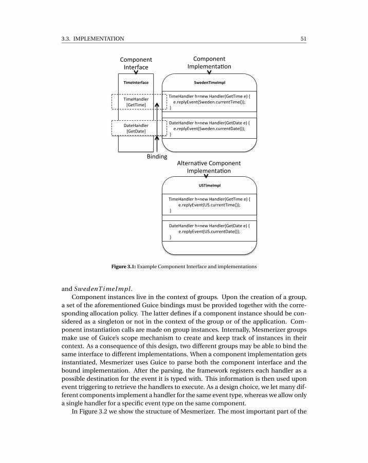
3.3. IMPLEMENTATION 51
!"#$%&'$()*+$,
!"#$%&'()$*+,-$.!"#$/+
0&.$%&'()$*+,-$.0&.$/+
-.$/$&!"#$%#01,
!"#$%&'()$*+12'$3+%&'()$*4-$.!"#$+$5+6+$7*$8)9:;$'.4<3$($'7=>**$'.!"#$455?+
++++@+
0&.$%&'()$*+12'$3+%&'()$*4-$.0&.$+$5+6+$7*$8)9:;$'.4<3$($'7=>**$'.0&.$455?+
++++@+
2-!"#$%#01,
!"#$%&'()$*+12'$3+%&'()$*4-$.!"#$+$5+6+$7*$8)9:;$'.4A<7=>**$'.!"#$455?+
++++@+
0&.$%&'()$*+12'$3+%&'()$*4-$.0&.$+$5+6+$7*$8)9:;$'.4A<7=>**$'.0&.$455?+
++++@+
BC#8C'$'.+D'.$*E&=$+
BC#8C'$'.+D#8)$#$'.&FC'+
G"'("'H+I).$*'&F;$+BC#8C'$'.+
D#8)$#$'.&FC'+
Figure 3.1: Example Component Interface and implementations
and SwedenT i meImpl .Component instances live in the context of groups. Upon the creation of a group,
a set of the aforementioned Guice bindings must be provided together with the corre-sponding allocation policy. The latter defines if a component instance should be con-sidered as a singleton or not in the context of the group or of the application. Com-ponent instantiation calls are made on group instances. Internally, Mesmerizer groupsmake use of Guice’s scope mechanism to create and keep track of instances in theircontext. As a consequence of this design, two different groups may be able to bind thesame interface to different implementations. When a component implementation getsinstantiated, Mesmerizer uses Guice to parse both the component interface and thebound implementation. After the parsing, the framework registers each handler as apossible destination for the event it is typed with. This information is then used uponevent triggering to retrieve the handlers to execute. As a design choice, we let many dif-ferent components implement a handler for the same event type, whereas we allow onlya single handler for a specific event type on the same component.
In Figure 3.2 we show the structure of Mesmerizer. The most important part of the
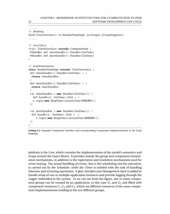
52
CHAPTER 3. MESMERIZER: AN EFFECTIVE TOOL FOR A COMPLETE PEER-TO-PEER
SOFTWARE DEVELOPMENT LIFE-CYCLE
. . . . . ./ / Bindingbind ( TimeInterface ) . to (SwedenTimeImpl) . as ( Scopes . GroupSingleton ). . . . . .
/ / I n t e r f a c et r a i t TimeInterface extends ComponentInt {@Handler def timeHandler ( ) : Handler [ GetTime ]@Handler def dateHandler ( ) : Handler [ GetDate ]
}
/ / Implementationclass SwedenTimeImpl extends TimeInterface {
def timeHandler ( ) : Handler [ GetTime ] = {return timeHandler ;
}def dateHandler ( ) : Handler [ GetDate ] = {
return dateHandler ;}val timeHandler = new Handler [ GetTime ] ( ) {
def handle ( e : GetTime ) : Unit = {e . reply (new RespTime ( currentTime (SWEDEN) ) )
} }
val dateHandler = new Handler [ GetDate ] ( ) {def handle ( e : GetDate ) : Unit = {
e . reply (new RespDate ( currentDate (SWEDEN) ) )} }
}
Listing 3.1: Example Component Interface and corresponding Component Implementations in the Scalalanguage
platform is the Core, which contains the implementation of the model’s semantics andwraps around the Guice library. It provides mainly the group and component instanti-ation mechanisms, in addition to the registration and resolution mechanisms used forevent routing. The actual handling of events, that is the scheduling and the execution,is carried out by the Scheduler, while the Timer is entitled with the task of handlingtimeouts and recurring operations. A glue Interface and Management layer is added tohandle setup of one or multiple application instances and provide logging through theLogger embedded in the system. As we can see from the figure, one or many compo-nent groups can be created by an application, in this case G1 and G2 and filled withcomponent instances C1,C2 and C3, which are different instances of the same compo-nent implementations residing in the two different groups.
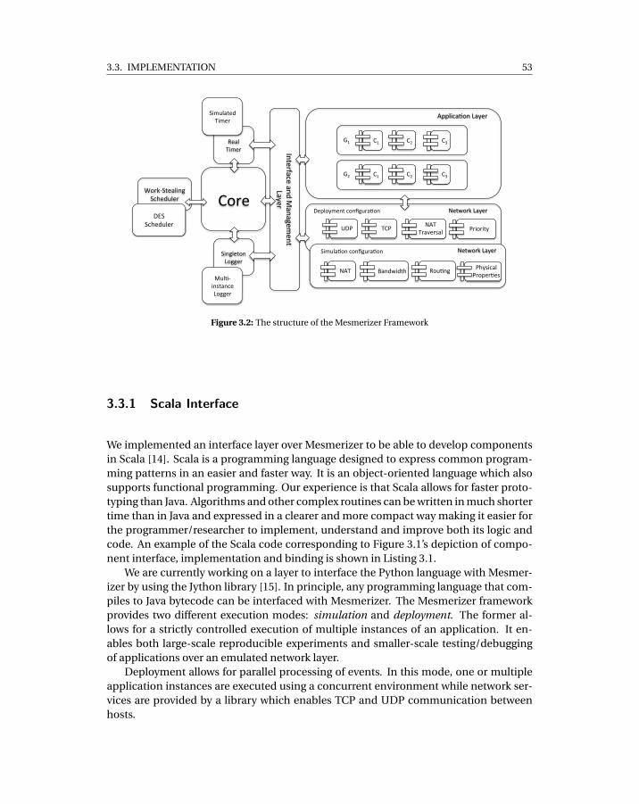
3.3. IMPLEMENTATION 53
!"#$%
&$'(%)*+$#%
,"#-./0$'(*12%/34$56($#%
710$#8'3$%'15%9'1'2$+
$10%:';$#%
<==(*3'>"1%:';$#%
!?% !@% !A%
!?% !@% !A%
B?%
B@%
C$0D"#-%:';$#%
EFG% )!G%C<)%
)#'H$#I'(%G#*"#*0;%
F$=(";+$10%3"1J26#'>"1%
C<)% K'15D*504%% &"6>12%
/*+6('>"1%3"1J26#'>"1% C$0D"#-%:';$#%
/*+6('0$5%)*+$#%
/*12($0"1%:"22$#%
96(>.*1I0'13$%:"22$#%
FL/%/34$56($#%
G4;I*3'(%G#"=$#>$I%
Figure 3.2: The structure of the Mesmerizer Framework
3.3.1 Scala Interface
We implemented an interface layer over Mesmerizer to be able to develop componentsin Scala [14]. Scala is a programming language designed to express common program-ming patterns in an easier and faster way. It is an object-oriented language which alsosupports functional programming. Our experience is that Scala allows for faster proto-typing than Java. Algorithms and other complex routines can be written in much shortertime than in Java and expressed in a clearer and more compact way making it easier forthe programmer/researcher to implement, understand and improve both its logic andcode. An example of the Scala code corresponding to Figure 3.1’s depiction of compo-nent interface, implementation and binding is shown in Listing 3.1.
We are currently working on a layer to interface the Python language with Mesmer-izer by using the Jython library [15]. In principle, any programming language that com-piles to Java bytecode can be interfaced with Mesmerizer. The Mesmerizer frameworkprovides two different execution modes: simulation and deployment. The former al-lows for a strictly controlled execution of multiple instances of an application. It en-ables both large-scale reproducible experiments and smaller-scale testing/debuggingof applications over an emulated network layer.
Deployment allows for parallel processing of events. In this mode, one or multipleapplication instances are executed using a concurrent environment while network ser-vices are provided by a library which enables TCP and UDP communication betweenhosts.
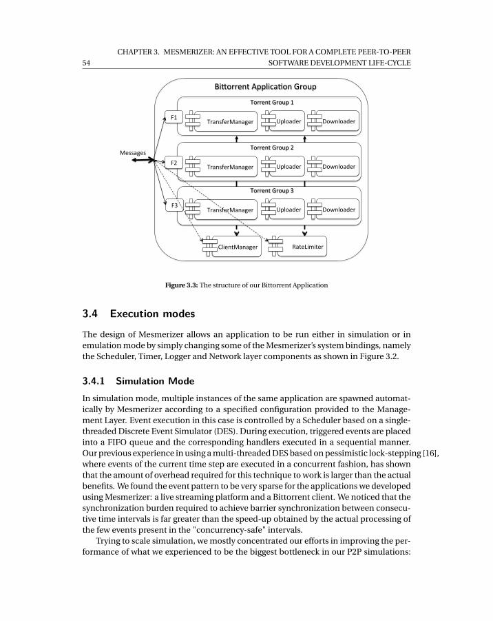
54
CHAPTER 3. MESMERIZER: AN EFFECTIVE TOOL FOR A COMPLETE PEER-TO-PEER
SOFTWARE DEVELOPMENT LIFE-CYCLE
Downloader
Bi-orrent Applica2on Group
Uploader TransferManager
Torrent Group 1
Downloader Uploader TransferManager
Torrent Group 2
Downloader Uploader TransferManager
Torrent Group 3
ClientManager RateLimiter
F1
F2
F3
Messages
Figure 3.3: The structure of our Bittorrent Application
3.4 Execution modes
The design of Mesmerizer allows an application to be run either in simulation or inemulation mode by simply changing some of the Mesmerizer’s system bindings, namelythe Scheduler, Timer, Logger and Network layer components as shown in Figure 3.2.
3.4.1 Simulation ModeIn simulation mode, multiple instances of the same application are spawned automat-ically by Mesmerizer according to a specified configuration provided to the Manage-ment Layer. Event execution in this case is controlled by a Scheduler based on a single-threaded Discrete Event Simulator (DES). During execution, triggered events are placedinto a FIFO queue and the corresponding handlers executed in a sequential manner.Our previous experience in using a multi-threaded DES based on pessimistic lock-stepping [16],where events of the current time step are executed in a concurrent fashion, has shownthat the amount of overhead required for this technique to work is larger than the actualbenefits. We found the event pattern to be very sparse for the applications we developedusing Mesmerizer: a live streaming platform and a Bittorrent client. We noticed that thesynchronization burden required to achieve barrier synchronization between consecu-tive time intervals is far greater than the speed-up obtained by the actual processing ofthe few events present in the "concurrency-safe" intervals.
Trying to scale simulation, we mostly concentrated our efforts in improving the per-formance of what we experienced to be the biggest bottleneck in our P2P simulations:
3.4. EXECUTION MODES 55
emulating bandwidth allocation dynamics of the network. We will show in Section 3.5.2how the Mesmerizer simulation environment performs in terms of scalability when em-ulating such phenomena and its level of accuracy with respect to other more costly so-lutions.
Simulation Setup. We provide a set of APIs which enable users to fully configurethe execution of multiple application instances and carefully control the behavior ofthe simulated network layer. Typically in simulation mode, Mesmerizer isolates an ap-plication instance in its own component group containing all of its components. Ap-plication instances communicate using the same network interface provided in deploy-ment mode. Messages are however routed to an emulated network layer which modelsa number of characteristics found in real networks.
For large-scale experiments, we implemented a number of churn generators basedon probabilistic and fixed time behaviors which can be configured either programmat-ically or through an XML scenario file. The emulated underlying network can also beconfigured in the same way. The Mesmerizer simulator allows for the creation of sce-narios containing a predefined number of peers interconnected using routers and NATboxes [17] on simple end-to-end topologies or more complicated consumer LAN infras-tructures and/or complex multi-layered corporate networks. The simulation APIs makepossible to define bandwidth capacities for each peer/router in the network, dictate thebehavior of NAT boxes and configure in detail network characteristics such as delay pat-terns, packet loss and link failures.
3.4.2 Deployment ModeDeployment allows for the execution of application instances in a concurrent environ-ment. In this mode, the handlers of the application’s components are processed onmultiple threads concurrently. From a component’s instance point of view, a number ofits safe handlers can run together at once, however, its unsafe handlers will be executedsequentially. On the other hand, many unsafe handlers of different components may beactive at the same point in time. In this mode, execution is controlled by a concurrentScheduler which implements the work-stealing paradigm introduced by Blumofe et al[18] on a number of Java threads, similarly to Kompics [7]. Work-stealing is an efficientscheduling scheme for multi-core machines which is based on an queuing mechanismwith low cost of synchronization. We make use of the work-stealing paradigm in the fol-lowing way: when an event gets scheduled, Mesmerizer finds the component instanceswhich subscribed to that particular event type and hands them to the Scheduler. TheScheduler then checks the availability of a number of free threads corresponding to thatof the passed handlers. If enough free threads are found, it schedules the handlers forimmediate execution. If no sufficient number of threads is available, the scheduler dis-tributes randomly the remaining handlers to the waiting queues of the currently occu-pied threads. When a thread completes the execution of a handler, it tries either to takean event from its queue or, if its queue is empty, it steals handlers from another thread’squeues. In our experience, this type of scheduling guarantees a good level of fairnessand avoids starvation of handlers.
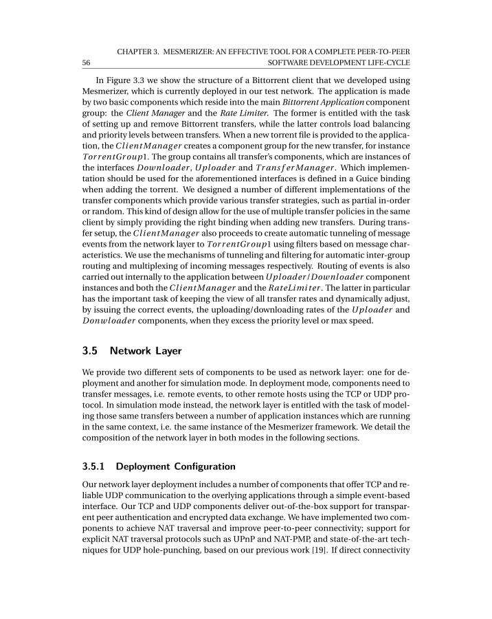
56
CHAPTER 3. MESMERIZER: AN EFFECTIVE TOOL FOR A COMPLETE PEER-TO-PEER
SOFTWARE DEVELOPMENT LIFE-CYCLE
In Figure 3.3 we show the structure of a Bittorrent client that we developed usingMesmerizer, which is currently deployed in our test network. The application is madeby two basic components which reside into the main Bittorrent Application componentgroup: the Client Manager and the Rate Limiter. The former is entitled with the taskof setting up and remove Bittorrent transfers, while the latter controls load balancingand priority levels between transfers. When a new torrent file is provided to the applica-tion, the C l i ent M anag er creates a component group for the new transfer, for instanceTor r entGr oup1. The group contains all transfer’s components, which are instances ofthe interfaces Downl oader , Uploader and Tr ans f er M anag er . Which implemen-tation should be used for the aforementioned interfaces is defined in a Guice bindingwhen adding the torrent. We designed a number of different implementations of thetransfer components which provide various transfer strategies, such as partial in-orderor random. This kind of design allow for the use of multiple transfer policies in the sameclient by simply providing the right binding when adding new transfers. During trans-fer setup, the C l i ent M anag er also proceeds to create automatic tunneling of messageevents from the network layer to Tor r entGr oup1 using filters based on message char-acteristics. We use the mechanisms of tunneling and filtering for automatic inter-grouprouting and multiplexing of incoming messages respectively. Routing of events is alsocarried out internally to the application between Uploader /Downl oader componentinstances and both the C l i ent M anag er and the RateLi mi ter . The latter in particularhas the important task of keeping the view of all transfer rates and dynamically adjust,by issuing the correct events, the uploading/downloading rates of the Uploader andDonwloader components, when they excess the priority level or max speed.
3.5 Network Layer
We provide two different sets of components to be used as network layer: one for de-ployment and another for simulation mode. In deployment mode, components need totransfer messages, i.e. remote events, to other remote hosts using the TCP or UDP pro-tocol. In simulation mode instead, the network layer is entitled with the task of model-ing those same transfers between a number of application instances which are runningin the same context, i.e. the same instance of the Mesmerizer framework. We detail thecomposition of the network layer in both modes in the following sections.
3.5.1 Deployment Configuration
Our network layer deployment includes a number of components that offer TCP and re-liable UDP communication to the overlying applications through a simple event-basedinterface. Our TCP and UDP components deliver out-of-the-box support for transpar-ent peer authentication and encrypted data exchange. We have implemented two com-ponents to achieve NAT traversal and improve peer-to-peer connectivity; support forexplicit NAT traversal protocols such as UPnP and NAT-PMP, and state-of-the-art tech-niques for UDP hole-punching, based on our previous work [19]. If direct connectivity
3.5. NETWORK LAYER 57
between two peers cannot be achieved, the network layer automatically relays the com-munication over a third host. However, we use this feature only for signaling purposesince relaying traffic is a very expensive operation, in particular for data intensive ap-plications such as video streaming or content delivery platforms where the amount ofdata to be transfered is significant.
On top of NAT traversal and reliable communication, the deployment network layerprovides three strategies for traffic prioritization based on different UDP congestioncontrol methods. For low priority traffic, we implemented the LEDBAT delay-basedcongestion control [20], which yields with respect to other concurrent TCP streams. Forwhat we call fair level of priority, or medium, we adopted a variation of the TCPReno[21] protocol which enables equal sharing of bandwidth among flows generated by ourlibrary and other applications using TCP. Finally, when the delivery of data is of crit-ical importance, the library provides high priority through an adaptation of the Mul-TCP [22] protocol. The level of priority can be dynamically chosen on a flow-to-flowbasis at runtime.
3.5.2 Simulation ConfigurationIn Simulation mode, we make use of a number of components which emulate differentaspects of the network. For instance, on the IP layer, we provide routing and NAT emu-lation through the corresponding components. For modeling lower layer network char-acteristics, we implemented components that model bandwidth allocation dynamics,non-deterministic delays and packet loss. As mentioned in Section 3.1, some of theseemulated characteristics are found in almost all P2P simulators. We detail the NAT andbandwidth emulation components; the first being notable for its novelty and the secondfor its high level of efficiency/accuracy trade-off.
NAT Emulation
Network Address Translators constitute a barrier for peer-to-peer applications. NATboxes prevent direct communication between peers behind different NAT boxes [17].Even though an attempt has been made to standardize Network Address Translation[23], in particular to improve support for Peer-To-Peer applications, not all vendors havecomplied to the standard. This is either because most of the routers ship with legacyNAT implementations or because manufacturers claim the standard to be too permis-sive. In particular, in the context of corporate NAT implementations, the translationbehavior may vary drastically between different vendors or even different models of thesame manufacturer.
In our previous work, we have tried to classify most of the behaviors of current NATimplementations using a real deployment of our test software. The outcome of this ef-fort is a model that encompasses 27 types of NATs as a combination of three behavioralpolicies: filtering, allocation and mapping. NAT traversal is a pairwise connection es-tablishment process: in order to establish a communication channel between machinesbehind two different NAT boxes, it is necessary to carry out a connection setup process
58
CHAPTER 3. MESMERIZER: AN EFFECTIVE TOOL FOR A COMPLETE PEER-TO-PEER
SOFTWARE DEVELOPMENT LIFE-CYCLE
dictated by a NAT traversal strategy, which should vary according to the type of the twoconsidered NAT boxes. Given a set of seven known traversal strategies, the NAT prob-lem translates to understanding which strategy should be used in each one of the 378possible combinations of the 27 NAT types. On top of that, each traversal strategy hasits own configuration parameters. These parameters could be as detailed as decidingwhich source port should be used locally by the two source hosts to initiate the setupprocess in order to maximize the connection establishment success probability.
At first, we tried to understand the mapping between NAT type combinations andtraversal strategies by formal reasoning. However, this task turned out to be too complexdue to the size of the possibility space. As a consequence of that, we developed a con-figurable NAT box implementation which could emulate all the aforementioned NATtypes. On top of it, we implemented a small simulator which would perform the pro-cess of traversal, according to the seven strategies, on all of the emulated 240 NAT typecombinations. By using this small framework, we discovered many counter-intuitiveaspects of NAT traversal and mistakes in the strategy’s decision process which we wouldnot have discovered by simple reasoning. The outcome of our effort of mapping strate-gies to combinations is described in [19].
For the purpose of testing the correct and non-trivial implementation of the Traver-sal strategies in our application, we included NAT emulation in the network layer con-figuration of Mesmerizer. In other words, we built an emulated network where the con-nection establishment process by means of NAT traversal is modeled in a very detailedmanner. Thus, we were able to test not only the correctness of our implementation ofthe traversal strategies, but also to measure the impact of the connection establishmentdelays on the overlying application. Delays are very important factors to be consideredwhen designing audio and video streaming systems, due to the time-constrained natureof the application.
The model which we designed for the emulation of NAT boxes encompasses mostof the behaviors which are found in current routers and corporate firewalls. However,after the deployment of our live streaming application on a real network, we noticed anumber of exceptional characteristics, e.g. non-deterministic NAT mapping timeouts,inconsistent port allocation behaviors and the presence of multiple filtering policies onthe same router. We thus tried to formalize those exceptions and integrate them intoour simulator. We further improved our simulator by modeling connection establish-ment failures based on real-world measurements. We emulate the observed probabilityof success between NAT types combinations according to what we observed during ourreal-world tests. Currently, we still experience cases that are not covered by our emula-tion model and we keep improving our model based on those observations. The sourcecode of our NAT box emulator is publicly available as an open source project [24].
The detailed emulation of NAT boxes has provided us with better insight on howpeer-to-peer applications should be designed and implemented in order to avoid con-nectivity issues.
3.5. NETWORK LAYER 59
Bandwidth Modeling
It is common for P2P networks to create complex interactions between thousands ofparticipant peers, where each peer typically has very high inbound and outbound con-nection degree [25] [26] [27]. Connections are used either for signaling or for contentpropagation. In the latter case, each peer implements intricate multiplexing strategiesto speed up transmission of large chunks of data [28], thus creating complex effects onthe underlying physical network which translate into varying transmission delays andpacket loss at the receiving side.
Most of the existing P2P simulators abstract away network interactions by model-ing only the structural dynamics of the overlay network [29] [30] [31] [32] [33] and thustotally ignoring the impact of the actual network on application performance. On theother end, accurate packet-level simulators like SSFNet [34] and NS-2 [12] can usuallyscale up only to a limited number of simulated peers. This limitation makes it infeasibleto capture the behavior and issues of a larger P2P real-word deployment, such as theeffect of network congestion on segments of the overlay network. In order to study thecomplex interactions between large scale overlays and the physical network, a propernetwork simulation model is required. The level on which the model abstracts the net-work transfers directly affects both its scalability and accuracy.
Flow-level network simulation focuses on a transfer as a whole rather than individ-ual packets, introducing a viable trade-off between accuracy and scalability. A flow ab-stracts away the small time scale rate variation of a packet sequence with a constant rateallocated at the sender/receiver’s bandwidth. The rate remains allocated for an amountof time which corresponds to the duration of the flow, i.e. the simulated packet se-quence transmission time. This approach reduces drastically the number of events tobe simulated. The driving force behind the event creation in flow-level simulation is theinteraction between the flows since an upload/download link might have many flowshappening at the same time. A new or completed flow might cause a rate change onother flows competing for that same link’s capacity. A flow rate change may also propa-gate further in the simulated network graph. This phenomenon is known as "the rippleeffect" and has been observed in a number of studies [35] [36]. The impact of the rip-ple effect on the scalability of the model is directly dependent on the efficiency of thebandwidth allocation algorithm which is used to mimic the bandwidth dynamics.
Bertsekas and Gallager [13] introduce the concept of max-min fairness for modelingAdditive-Increase Multiplicative-Decrease congestion control protocols like TCP. Max-min fairness tries to maximize the bandwidth allocated to the flows within a minimumshare thus guaranteeing that no flow can increase its rate at the cost of a flow with alower rate. In every network exists a unique max-min fair bandwidth allocation and canbe calculated using the progressive filling algorithm [13]. The basic idea behind thisalgorithm is to start from a situation where all flow rates are zero and then progressivelyincrement each rate equally until reaching the link’s capacity, i.e. the sum of all flowrates of a link equals its capacity. In this algorithm, the network, including its internalstructure, e.g. routers and backbone links, is modeled as an undirected graph. A recentaccuracy study [37] showed that this approach offers a good approximation of the actual
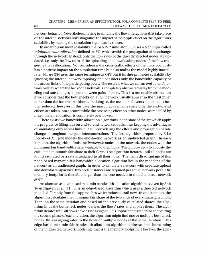
60
CHAPTER 3. MESMERIZER: AN EFFECTIVE TOOL FOR A COMPLETE PEER-TO-PEER
SOFTWARE DEVELOPMENT LIFE-CYCLE
network behavior. Nevertheless, having to simulate the flow interactions that take placeon the internal network links magnifies the impact of the ripple effect on the algorithm’sscalability by making the simulation significantly slower.
In order to gain more scalability, the GPS P2P simulator [38] uses a technique calledminimum-share allocation, defined in [39], which avoids the propagation of rate changesthrough the network. Instead, only the flow rates of the directly affected nodes are up-dated, i.e. only the flow rates of the uploading and downloading nodes of the flow trig-gering the reallocation. Not considering the cross-traffic effects of the flows obviouslyhas a positive impact on the simulation time but also makes the model highly inaccu-rate. Narses [39] uses the same technique as GPS but it further promotes scalability byignoring the internal network topology and considers only the bandwidth capacity ofthe access links of the participating peers. The result is what we call an end-to-end net-work overlay where the backbone network is completely abstracted away from the mod-eling and rate changes happen between pairs of peers. This is a reasonable abstractionif we consider that the bottlenecks on a P2P network usually appear in the "last mile"rather than the internet backbone. In doing so, the number of events simulated is fur-ther reduced, however in this case the inaccuracy remains since only the end-to-endeffects are taken into account while the cascading effect on other nodes, as modeled bymax-min fair allocation, is completely overlooked.
There exists two bandwidth allocation algorithms in the state of the art which applythe progressive filling idea on end-to-end network models, thus keeping the advantagesof simulating only access links but still considering the effects and propagation of ratechanges throughout the peer interconnections. The first algorithm proposed by F. LoPiccolo et Al. [40] models the end-to-end network as an undirected graph. In eachiteration, the algorithm finds the bottleneck nodes in the network, the nodes with theminimum fair bandwidth share available to their flows. Then it proceeds to allocate thecalculated minimum fair share to their flows. The algorithm iterates until all nodes arefound saturated or a rate is assigned to all their flows. The main disadvantage of thisnode-based max-min fair bandwidth allocation algorithm lies in the modeling of thenetwork as an undirected graph. In order to simulate a network with separate uploadand download capacities, two node instances are required per actual network peer. Thememory footprint is therefore larger than the one needed to model a direct networkgraph.
An alternative edge-based max-min bandwidth allocation algorithm is given by AnhTuan Nguyen et al. [41]. It is an edge-based algorithm which uses a directed networkmodel, differently from the approaches we introduced until now. In one iteration, thealgorithm calculates the minimum fair share of the two ends of every unassigned flow.Then, on the same iteration and based on the previously calculated shares, the algo-rithm finds the bottleneck nodes, derives the flows’ rates and applies them. The algo-rithm iterates until all flows have a rate assigned. It is important to underline that duringthe second phase of each iteration, the algorithm might find one or multiple bottlenecknodes, thus assigning rates to the flows of multiple nodes at the same iteration. Thisedge-based max-min fair bandwidth allocation algorithm addresses the shortcomingof the undirected network modeling, that is the memory footprint. However, the algo-
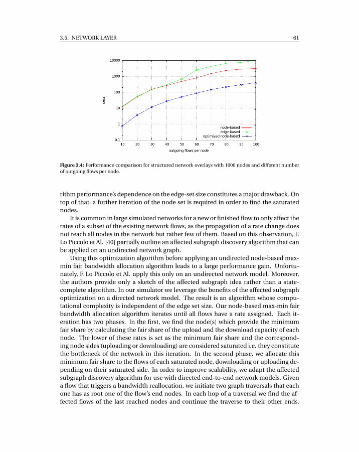
3.5. NETWORK LAYER 61
Figure 3.4: Performance comparison for structured network overlays with 1000 nodes and different numberof outgoing flows per node.
rithm performance’s dependence on the edge-set size constitutes a major drawback. Ontop of that, a further iteration of the node set is required in order to find the saturatednodes.
It is common in large simulated networks for a new or finished flow to only affect therates of a subset of the existing network flows, as the propagation of a rate change doesnot reach all nodes in the network but rather few of them. Based on this observation, F.Lo Piccolo et Al. [40] partially outline an affected subgraph discovery algorithm that canbe applied on an undirected network graph.
Using this optimization algorithm before applying an undirected node-based max-min fair bandwidth allocation algorithm leads to a large performance gain. Unfortu-nately, F. Lo Piccolo et Al. apply this only on an undirected network model. Moreover,the authors provide only a sketch of the affected subgraph idea rather than a state-complete algorithm. In our simulator we leverage the benefits of the affected subgraphoptimization on a directed network model. The result is an algorithm whose compu-tational complexity is independent of the edge set size. Our node-based max-min fairbandwidth allocation algorithm iterates until all flows have a rate assigned. Each it-eration has two phases. In the first, we find the node(s) which provide the minimumfair share by calculating the fair share of the upload and the download capacity of eachnode. The lower of these rates is set as the minimum fair share and the correspond-ing node sides (uploading or downloading) are considered saturated i.e. they constitutethe bottleneck of the network in this iteration. In the second phase, we allocate thisminimum fair share to the flows of each saturated node, downloading or uploading de-pending on their saturated side. In order to improve scalability, we adapt the affectedsubgraph discovery algorithm for use with directed end-to-end network models. Givena flow that triggers a bandwidth reallocation, we initiate two graph traversals that eachone has as root one of the flow’s end nodes. In each hop of a traversal we find the af-fected flows of the last reached nodes and continue the traverse to their other ends.
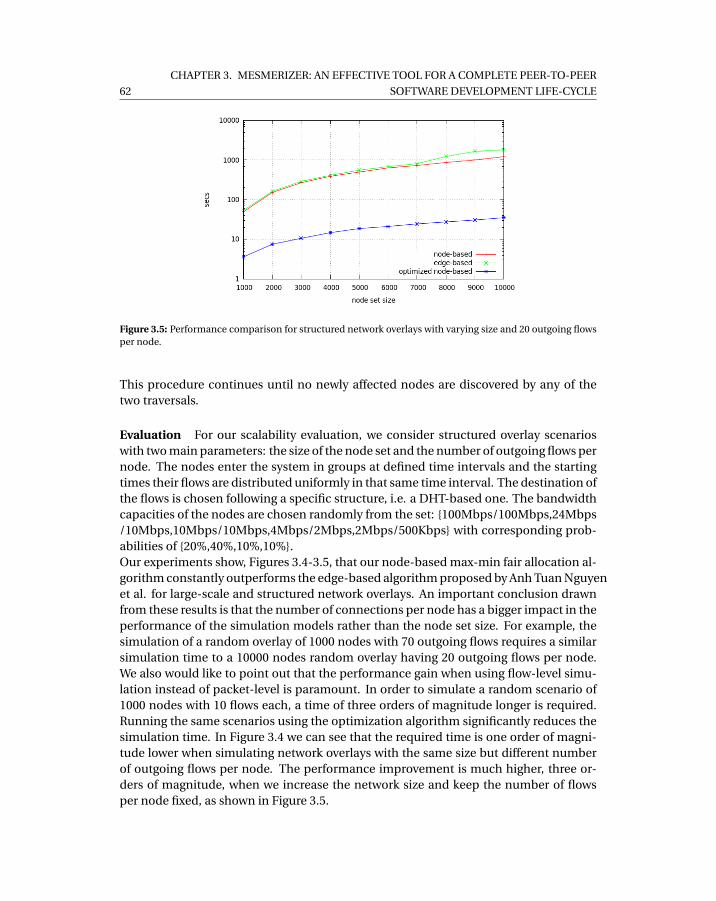
62
CHAPTER 3. MESMERIZER: AN EFFECTIVE TOOL FOR A COMPLETE PEER-TO-PEER
SOFTWARE DEVELOPMENT LIFE-CYCLE
Figure 3.5: Performance comparison for structured network overlays with varying size and 20 outgoing flowsper node.
This procedure continues until no newly affected nodes are discovered by any of thetwo traversals.
Evaluation For our scalability evaluation, we consider structured overlay scenarioswith two main parameters: the size of the node set and the number of outgoing flows pernode. The nodes enter the system in groups at defined time intervals and the startingtimes their flows are distributed uniformly in that same time interval. The destination ofthe flows is chosen following a specific structure, i.e. a DHT-based one. The bandwidthcapacities of the nodes are chosen randomly from the set: {100Mbps/100Mbps,24Mbps/10Mbps,10Mbps/10Mbps,4Mbps/2Mbps,2Mbps/500Kbps} with corresponding prob-abilities of {20%,40%,10%,10%}.Our experiments show, Figures 3.4-3.5, that our node-based max-min fair allocation al-gorithm constantly outperforms the edge-based algorithm proposed by Anh Tuan Nguyenet al. for large-scale and structured network overlays. An important conclusion drawnfrom these results is that the number of connections per node has a bigger impact in theperformance of the simulation models rather than the node set size. For example, thesimulation of a random overlay of 1000 nodes with 70 outgoing flows requires a similarsimulation time to a 10000 nodes random overlay having 20 outgoing flows per node.We also would like to point out that the performance gain when using flow-level simu-lation instead of packet-level is paramount. In order to simulate a random scenario of1000 nodes with 10 flows each, a time of three orders of magnitude longer is required.Running the same scenarios using the optimization algorithm significantly reduces thesimulation time. In Figure 3.4 we can see that the required time is one order of magni-tude lower when simulating network overlays with the same size but different numberof outgoing flows per node. The performance improvement is much higher, three or-ders of magnitude, when we increase the network size and keep the number of flowsper node fixed, as shown in Figure 3.5.

3.6. CONCLUSION & FUTURE WORK 63
cu/cd flows std. deviation avg. deviation
20/10
10 3.8±0.4% 3±0.4%20 3.9±0.2% 3.1±0.1%30 4.1±0.3% 3.3±0.2%40 3.4±0.2% 2.8±0.2%50 3±0.1% 2.5±0.2%
20/10,10/10
10 6.4±0.4% 5±0.4%20 6±0.4% 4.9±0.3%30 4.8±0.4% 3.9±0.3%40 3.4±0.9% 3.2±0.3%50 3.5±0.2% 2.8±0.2%
Table 3.1: Deviation of simulated transfer times.
Finally, in our accuracy study we compare the simulated transfer times of our pro-posed solution with the ones obtained with NS-2 for the same scenarios. In NS-2, we usea simple star topology, similar to the one used in [37] [42]. Each node has a single accesslink which we configure with corresponding upload and download capacities. All flowspass from the source access link to the destination access link through a central nodewith infinite bandwidth capacity. Unfortunately, the size of our experiments is limitedby the low scalability of NS-2. We run scenarios of 100 nodes with a number of flows pernode that varies between 10 and 50. The size of each flow is 4MB and the bandwidth ca-pacities of a node are either asymmetric, 20Mbps/10Mbps, or mixed, 20Mbps/10Mbpsand 10Mbps/10Mbps. The results of our experiments are shown in Table 3.1. We can seethat our flow-level max-min fair bandwidth allocation follows the trends of the actualpacket-level simulated bandwidth dynamics by a nearly constant factor throughout theexperiments. We can see that the presence of the symmetric capacities affects the trans-fer time deviation negatively. The negative impact is more visible when fewer outgoingflows per node are used. When the links are less congested, the slower convergence ofthe flow rates of the nodes with smaller symmetric capacities is more apparent.
3.6 Conclusion & Future Work
In this paper we presented what we found to be the three most important practicesin P2P software development: a simulation-based development cycle, a clear concur-rency model, and a realistic network model when running in simulation mode. We thenpresented the Mesmerizer framework which we built to encompass all the aforemen-tioned. We detailed its design and implementation and how it can be used both forcontrolled evaluation/testing/debugging and deployment of production code. Regard-ing simulation-based development, we stress how NAT box and bandwidth dynamicsemulation are of vital importance when testing a large number of a P2P application in-stances. From the point of view of the scalability, we demonstrate that our simulationframework is able to emulate the bandwidth characteristics of thousands of peers while
64
CHAPTER 3. MESMERIZER: AN EFFECTIVE TOOL FOR A COMPLETE PEER-TO-PEER
SOFTWARE DEVELOPMENT LIFE-CYCLE
preserving a good level of accuracy compared to the NS2 packet-level simulator.Our ongoing work includes the improvement of the NAT and bandwidth emulation
model’s accuracy and the release of all our utilities as open source software.
3.7 References
[1] Ruby on rails. http://rubyonrails.org/.
[2] django. http://www.djangoproject.com/.
[3] Jesse James Garrett. Ajax: A new approach to web applications.http://adaptivepath.com/ideas/essays/archives/000385.php, February 2005.URL http://adaptivepath.com/ideas/essays/archives/000385.php.[Online; Stand 18.03.2008].
[4] Comet. http://cometdaily.com/.
[5] Roberto Roverso, Mohammed Al-Aggan, Amgad Naiem, Andreas Dahlstrom,Sameh El-Ansary, Mohammed El-Beltagy, and Seif Haridi. Myp2pworld: Highly re-producible application-level emulation of p2p systems. In Decentralized Self Man-agement for Grid, P2P, User Communities workshop, SASO 2008, 2008.
[6] Google guice. http://code.google.com/p/google-guice.
[7] C. Arad, J. Dowling, and S. Haridi. Building and evaluating p2p systems using thekompics component framework. In Peer-to-Peer Computing, 2009. P2P ’09. IEEENinth International Conference on, pages 93 –94, sept. 2009.
[8] Galuba W. et al. Protopeer: A p2p toolkit bridging the gap between simulationand live deployement. 2nd International ICST Conference on Simulation Tools andTechniques, May 2009.
[9] Ron Hitchens. Java Nio. O’Reilly & Associates, Inc., Sebastopol, CA, USA, 2002.ISBN 0596002882.
[10] Gul Abdulnabi Agha. Actors: a model of concurrent computation in distributedsystems. MIT Press, 1985.
[11] Philipp Haller and Martin Odersky. Scala actors: Unifying thread-based and event-based programming. Theor. Comput. Sci., 410(2-3):202–220, February 2009. ISSN0304-3975. URL http://dx.doi.org/10.1016/j.tcs.2008.09.019.
[12] The ns-2 network simulator. http://www.isi.edu/nsnam/ns/, October 2010.
[13] Dimitri Bertsekas and Robert Gallager. Data Networks. Prentice Hall, second edi-tion, 1992.
3.7. REFERENCES 65
[14] Martin Odersky, Lex Spoon, and Bill Venners. Programming in Scala: A Compre-hensive Step-by-step Guide. Artima Incorporation, USA, 1st edition, 2008. ISBN0981531601, 9780981531601.
[15] The jython project. http://www.jython.org/.
[16] Shiding Lin, Aimin Pan, Rui Guo, and Zheng Zhang. Simulating large-scale p2p sys-tems with the wids toolkit. In Modeling, Analysis, and Simulation of Computer andTelecommunication Systems, 2005. 13th IEEE International Symposium on, pages415 – 424, sept. 2005.
[17] P. Srisuresh, B. Ford, and D. Kegel. State of Peer-to-Peer (P2P) Communicationacross Network Address Translators (NATs). RFC 5128 (Informational), March 2008.URL http://www.ietf.org/rfc/rfc5128.txt.
[18] R.D. Blumofe and C.E. Leiserson. Scheduling multithreaded computations by workstealing. In Foundations of Computer Science, 1994 Proceedings., 35th Annual Sym-posium on, pages 356 –368, November 1994.
[19] Roberto Roverso, Sameh El-Ansary, and Seif Haridi. Natcracker: Nat combinationsmatter. In Proceedings of the 2009 Proceedings of 18th International Conferenceon Computer Communications and Networks, ICCCN ’09, pages 1–7, Washington,DC, USA, 2009. IEEE Computer Society. ISBN Bad - remove. URL http://dx.doi.org/10.1109/ICCCN.2009.5235278.
[20] S Shalunov. Low extra delay background transport (ledbat) [online].http://tools.ietf.org/html/draft-ietf-ledbat-congestion-02.
[21] J. Mo, R.J. La, V. Anantharam, and J. Walrand. Analysis and comparison of TCPReno and Vegas. IEEE INFOCOM ’99, 1999. URL http://ieeexplore.ieee.org/lpdocs/epic03/wrapper.htm?arnumber=752178.
[22] J Crowcroft and P Oechslin. Differentiated end-to-end Internet services using aweighted proportional fair sharing TCP. ACM SIGCOMM Computer, 1998. URLhttp://portal.acm.org/citation.cfm?id=293927.293930.
[23] F. Audet and C. Jennings. Network Address Translation (NAT) Behavioral Require-ments for Unicast UDP. RFC 4787 (Best Current Practice), January 2007. URLhttp://www.ietf.org/rfc/rfc4787.txt.
[24] Roberto Roverso. NATCracker Box Emulator Software.http://code.google.com/p/natcracker/.
[25] Anwar Al Hamra, Arnaud Legout, and Chadi Barakat. Understanding the proper-ties of the bittorrent overlay. Technical report, INRIA, 2007.
66
CHAPTER 3. MESMERIZER: AN EFFECTIVE TOOL FOR A COMPLETE PEER-TO-PEER
SOFTWARE DEVELOPMENT LIFE-CYCLE
[26] Chuan Wu, Baochun Li, and Shuqiao Zhao. Magellan: Charting large-scale peer-to-peer live streaming topologies. In ICDCS ’07: Proceedings of the 27th Interna-tional Conference on Distributed Computing Systems, page 62, Washington, DC,USA, 2007. IEEE Computer Society.
[27] Guillaume Urvoy-Keller and Pietro Michiardi. Impact of inner parameters andoverlay structure on the performance of bittorrent. In INFOCOM ’06: Proceedingsof the 25th Conference on Computer Communications, 2006.
[28] B. Cohen. Incentives Build Robustness in BitTorrent. In Econ ’04: Proceedings ofthe Workshop on Economics of Peer-to-Peer Systems, Berkley, CA, USA, June 2003.
[29] Ingmar Baumgart, Bernhard Heep, and Stephan Krause. Oversim: A flexible over-lay network simulation framework. In GI ’07: Proceedings of 10th IEEE Global In-ternet Symposium, pages 79–84, Anchorage, AL, USA, May 2007.
[30] Sam Joseph. An extendible open source p2p simulator. P2P Journal, 0:1–15, 2003.
[31] Jordi Pujol-Ahullo, Pedro Garcia-Lopez, Marc Sanchez-Artigas, and Marcel Arrufat-Arias. An extensible simulation tool for overlay networks and services. In SAC ’09:Proceedings of the 24th ACM Symposium on Applied Computing, pages 2072–2076,New York, NY, USA, March 2009. ACM.
[32] Alberto Montresor Mark Jelasity and Ozalp Babaoglu. A modular paradigm forbuilding self-organizing peer-to-peer applications. In Engineering Self-OrganisingSystems, pages 265–282, 2003.
[33] Nyik San Ting and Ralph Deters. 3ls - a peer-to-peer network simulator. In P2P ’03:Proceedings of the 3rd International Conference on Peer-to-Peer Computing, page212. IEEE Computer Society, August 2003.
[34] Sunghyun Yoon and Young Boo Kim. A design of network simulation environmentusing ssfnet. pages 73–78, 2009. URL http://portal.acm.org/citation.cfm?id=1637862.1638154.
[35] G. Kesidis, A. Singh, D. Cheung, and W.W. Kwok. Feasibility of fluid event-drivensimulation for atm networks. In GLOBECOM ’96: Proceedings of the Global Com-munications Conference, volume 3, pages 2013 –2017, November 1996.
[36] Daniel R. Figueiredo, Benyuan Liu, Yang Guo, James F. Kurose, and Donald F.Towsley. On the efficiency of fluid simulation of networks. Computer Networks,50(12):1974–1994, 2006.
[37] Abdulhalim Dandoush and Alain Jean-Marie. Flow-level modeling of paralleldownload in distributed systems. In CTRQ ’10: Third International Conference onCommunication Theory, Reliability, and Quality of Service, pages 92 –97, june 2010.
3.7. REFERENCES 67
[38] W. Yang and N Abu-Ghazaleh. Gps: a general peer-to-peer simulator and its usefor modeling bittorrent. In MASCOTS ’05: Proceedings of 13th IEEE InternationalSymposium on Modeling, Analysis, and Simulation of Computer and Telecommu-nication Systems, pages 425–432, Atlanta, Georgia, USA, September 2005.
[39] Thomas J. Giuli and Mary Baker. Narses: A scalable flow-based network simulator.Computing Research Repository, cs.PF/0211024, 2002.
[40] F. Lo Piccolo, G. Bianchi, and S. Cassella. Efficient simulation of bandwidth alloca-tion dynamics in p2p networks. In GLOBECOM ’06: Proceedings of the 49th GlobalTelecommunications Conference, pages 1–6, San Franscisco, California, November2006.
[41] Anh Tuan Nguyen and F. Eliassen. An efficient solution for max-min fair rate allo-cation in p2p simulation. In ICUMT ’09: Proceedings of the International Confer-ence on Ultra Modern Telecommunications Workshops, pages 1 –5, St. Petersburg,Russia, October 2009.
[42] Tobias Hossfeld, Andreas Binzenhofer, Daniel Schlosser, Kolja Eger, Jens Oberen-der, Ivan Dedinski, and Gerald Kunzmann. Towards efficient simulation of largescale p2p networks. Technical Report 371, University of Wurzburg, Institute ofComputer Science, Am Hubland, 97074 Wurzburg, Germany, October 2005.


CH
AP
TE
R
4ACCURATE AND EFFICIENT SIMULATION
OF BANDWIDTH DYNAMICS FOR
PEER-TO-PEER OVERLAY NETWORKS

4.1. INTRODUCTION 71
Accurate and Efficient Simulation of BandwidthDynamics for Peer-To-Peer Overlay Networks
Alexandros Gkogkas1,2, Roberto Roverso1,2 and Seif Haridi2
1Peerialism ABStockholm, Sweden
[roberto,sameh]@peerialism.com
2KTH - Royal Institute of TechnologyStockholm, Sweden[haridi]@kth.se
Abstract
When evaluating Peer-to-Peer content distribution systems by means of simula-tion, it is of vital importance to correctly mimic the bandwidth dynamics behavior ofthe underlying network. In this paper, we propose a scalable and accurate flow-levelnetwork simulation model based on an evolution of the classical progressive fillingalgorithm which implements the max-min fairness idea. We build on top of the cur-rent state of art by applying an optimization to reduce the cost of each bandwidthallocation/deallocation operation on a node-based directed network model. Unlikeother works, our evaluation of the chosen approach focuses both on efficiency andon accuracy. Our experiments show that, in terms of scalability, our bandwidth allo-cation algorithm outperforms existing directed models when simulating large-scalestructured overlay networks. Whereas, in terms of accuracy we show that allocationdynamics of the proposed solution follow those of the NS-2 packet-level simula-tor by a small and nearly constant offset for the same scenarios. To the best of ourknowledge, this is the first time that an accuracy study has been conducted on animprovement of the classical progressive filling algorithm.
4.1 Introduction
It is common for existing P2P networks to create complex interactions between thou-sands of participant peers. Each peer usually has a very high inbound and outbound
72
CHAPTER 4. ACCURATE AND EFFICIENT SIMULATION OF BANDWIDTH DYNAMICS FOR
PEER-TO-PEER OVERLAY NETWORKS
connection degree [1] [2] [3]. Connections are used either for signaling or content prop-agation. In the latter case, each peer implements intricate multiplexing strategies tospeed up transmission of large chunks of data [4], thus creating complex effects onthe underlying physical network which translate into varying transmission delays andpacket loss at the receiving side.
In order to study the complex interactions between overlays and physical networks,a proper performance evaluation technique is required. Currently, no consensus hasbeen reached in the scientific community on a reference P2P testing platform [5]. It is ofa common practice to test a P2P application in a simulator before real deployment in or-der to enable controlled testing and evaluation. However, accurate network simulatorscan usually scale up only to a limited number of simulated peers. This limitation makesit infeasible to capture the behaviour and issues of a larger P2P real-word deployment,such as the effect network congestion on segments of the overlay network. In order toachieve scalability, most of the existing P2P simulators abstract away network interac-tions by modeling only the structural dynamics of the overlay network [6] [7] [8] [9] [10]and thus totally ignoring the impact of the actual network on application performance.
Packet-level network simulation allows for in-depth study of the influence of thenetwork characteristics and the lower level protocols on the performance of a P2P sys-tem. The trade-off for this detailed analysis comes in scalability: a single transfer cangenerate hundreds of low-level protocol packets. In a large and complex network char-acterised by links of high bandwidth capacity and intense in-line traffic, the sheer num-ber of events needed to simulate the transfers require a prohibitive amount of computa-tional and memory resources. As a result, only small sized networks can be simulated ef-ficiently. A number of packet-level network simulation frameworks has been conceivedin the last decade [11] [12], being NS-2 [13] the most prominent among them. In turn,a number of P2P network simulators have been developed on top of NS-2, e.g. P2PSim[14] and NDP2PSim [15].
Flow-level simulation focuses instead on a transfer as a whole rather than individ-ual packets, introducing a viable trade-off between accuracy and scalability. A flow ab-stracts away the small time scale rate variation of a packet sequence with a constantrate allocated at the sender/receiver’s bandwidth. The rate remains allocated for anamount of time which corresponds to the duration of the flow, i.e. the simulated packetsequence transmission time. This approach reduces drastically the number of eventsto be simulated. The driving force behind the event creation in flow-level simulationis the interaction between the flows, since an upload/download link might have manyflows happening at the same time. A new or completed flow might cause a rate changeon other flows competing for that same link’s capacity. For instance, in order for a linkto accommodate an extra flow, bandwidth needs to be allocated to it. This might leadto a decrease of the bandwidth rates of other competing flows. Similarly, when a flow iscompleted, more bandwidth becomes available for the other flows to share. A flow ratechange may also propagate further in the simulated network graph. This phenomenonis known as "the ripple effect" and has been observed in a number of studies [16] [17] .The impact of the ripple effect on the scalability of the model is directly dependent onthe efficiency of the bandwidth allocation algorithm.
4.2. RELATED WORK 73
In this paper we provide a description of the current state of the art in flow-levelnetwork bandwidth simulation in Section 4.2. Later we present a concise description ofour contribution in Section 4.3, before delving into the details of the proposed modelin Section 4. We then discuss the results of the scalability and accuracy evaluation ofour implementation in Section 5 and, finally, in Section 6, we draw our conclusions anddiscuss future work.
4.2 Related Work
Flow-level network simulators implement algorithms which mimic the bandwidth dy-namics happening in the transport protocol layer used of the real network. Bertsekasand Gallager [18] introduce the concept of max-min fairness for modeling Additive-Increase Multiplicative-Decrease congestion control protocols like TCP. Max-min fair-ness tries to maximize the bandwidth allocated to the flows with minimum share thusguaranteeing that no flow can increase its rate at the cost of a flow with a lower rate. Inevery network exists a unique max-min fair bandwidth allocation and can be calculatedusing the progressive filling algorithm [18]. The basic idea behind this algorithm is tostart from a situation where all flow rates are zero and then progressively increment eachrate equally until reaching the link’s capacity, i.e. the sum of all flow rates of a link equalsits capacity. In this algorithm, the network, including its internal structure, e.g. routersand backbone links, is modeled as an undirected graph. A recent accuracy study [19]showed that this approach offers a good approximation of the actual network behavior.Nevertheless, having to simulate the flow interactions that take place on the internalnetwork links, magnifies the impact of the ripple effect on the algorithm’s scalability bymaking the simulation significantly slower.
In order to gain more scalability, the GPS P2P simulator [20] uses a technique calledminimum-share allocation, defined in [21], which avoids the propagation of rate changesthrough the network. Instead, only the flow rates of the directly affected nodes are up-dated, i.e. only the flow rates of the uploading and downloading nodes of the flow trig-gering the reallocation. Not considering the cross-traffic effects of the flows obviouslyhas a positive impact on the simulation time but makes also the model highly inaccu-rate.
Narses [21] uses the same technique as GPS but it further promotes scalability byignoring the internal network topology and considering only the bandwidth capacityof the access links of the participating peers. The result is what we call an end-to-endnetwork overlay where the backbone network is completely abstracted away from themodeling and rate changes happen between pairs of peers. This is a reasonable ab-straction if we consider that the bottlenecks on a P2P network usually appear in the"last mile" rather than the Internet backbone. In doing so, the number of events sim-ulated is further reduced, however in this case the inaccuracy remains since only theend-to-end effects are taken into account while the cascading effect on other nodes, asmodeled by max-min fair allocation, is completely overlooked.
There exists two bandwidth allocation algorithms in the state of the art which apply
74
CHAPTER 4. ACCURATE AND EFFICIENT SIMULATION OF BANDWIDTH DYNAMICS FOR
PEER-TO-PEER OVERLAY NETWORKS
the progressive filling idea on end-to-end network models, thus keeping the advantagesof simulating only access links but still considering the effects and propagation of ratechanges throughout the peer interconnections. The first algorithm proposed by F. LoPiccolo et Al. [22] models the end-to-end network as an undirected graph. In eachiteration, the algorithm finds the bottleneck nodes in the network, the nodes with theminimum fair bandwidth share available to their flows. Then it proceeds to allocate thecalculated minimum fair share to the flows. The algorithm iterates until all nodes arefound saturated or a rate is assigned to all their flows.
The main disadvantage of this node-based max-min fair bandwidth allocation algo-rithm lies in the modeling of the network as an undirected graph. In order to simulatea network with separate upload and download capacities, two node instances are re-quired per actual network peer. The memory footprint is therefore larger than the oneneeded to model a direct network graph. Another weakness is that the computationalcomplexity of the approach depends directly on the cardinality of the node set.
An alternative edge-based max-min bandwidth allocation algorithm is given by AnhTuan Nguyen et al. [23]. It is an edge-based algorithm which uses a directed networkmodel, differently from the approaches we introduced till now. In one iteration, the al-gorithm calculates the minimum fair share of the two ends of every unassigned flow.Then, on the same iteration and based on the previously calculated shares, the algo-rithm finds the bottleneck nodes, derives the flows’ rates and applies them. The algo-rithm iterates until all flows have a rate assigned. It is important to underline that dur-ing the first phase of each iteration, the algorithm might find one or multiple bottlenecknodes, thus assigning rates to the flows of multiple nodes at the same iteration.
This edge-based max-min fair bandwidth allocation algorithm addresses the short-comings of the undirected network modeling. However, the algorithm performance’sdependence on the edge-set size constitutes a major drawback. This because each iter-ation requires the calculation of the minimum fair share for each unassigned flow. Ontop of that, a further iteration of the node set is required in order to find the saturatednodes. As we will see, this hidden complexity makes it unsuitable for simulating largenetworks with high adjacency.
It is common in large simulated networks for a new or finished flow to only affect therates of a subset of the existing network flows, as the propagation of a rate change doesnot reach all nodes in the network but rather few of them. Based on this observation,F. Lo Piccolo et Al. [22] partially outline an affected subgraph traversal algorithm thatcan be applied on an undirected network graph. Starting from the end nodes of the flowtriggering the reallocation, the algorithm traverses the segment of the network graphthat is affected by the change. In fact, this is an attempt to trace the aforementionedripple effect. The traverse continues through affected flows/edges until all the affectednetwork subgraph is visited. The nodes reached by the traversal are treated based onthe parity of the hop distance (odd or even) from any of the two root nodes, i.e. theinitiators of the allocation/deallocation. Depending on the parity, a different subset oftheir flows is affected. The traverse continues until no new nodes are affected. Since anode can be reached in an odd or even hop distance from a root, a node can be visitedmaximum twice during a traverse. This results in a linear complexity with respect to the
4.3. CONTRIBUTION 75
node set cardinality, assuming that a node is not reconsidered when reached again inthe same distance from a root.
Using this optimization algorithm before applying an undirected node-based max-min fair bandwidth allocation algorithm leads to a large performance gain. Unfortu-nately, F. Lo Piccolo et Al. apply this only on an undirected network model. Moreover,the authors provide only a sketch of the affected subgraph idea rather than a state-complete algorithm.
In general, the aforementioned works which propose an improvement to the clas-sical progressive filling focus their evaluation of the algorithms on performance whilecompletely overlooking the accuracy of their approaches.
4.3 Contribution
We propose a scalable and efficient flow-level simulator which leverages the benefitsof the affected subgraph optimization on a directed network model. We give a state-complete description of the subgraph optimization introduced by F. Lo Piccolo et Al.and we evaluate its performance gain when used in combination with our max-minfair bandwidth allocation algorithm. The result is an algorithm whose computationalcomplexity is independent of the edge set size. Our experiments show that our solutionconstantly outperforms the edge-based algorithm proposed by Anh Tuan Nguyen et al.for large-scale and structured network overlays. Finally, we conduct a detailed accuracystudy where we compare the simulated transfer times of our proposed solution with theones obtained with NS-2 for the same realistic scenarios. We show that the bandwidthallocation follows the trends of the actual packet-level simulated bandwidth dynamics.
4.4 Proposed Solution
We model the network as a directed graph G = (U ,F ), where the vertex set U representsthe set of end nodes and the edge set F represents the set of directed flows betweenpairs of end nodes. We define as cu
i and cdi the uploading and downloading capacities
of node i which belongs to the node set U . The rate of a flow fi j is denoted as ri j wherei , j ∈U and i 6= j . The existence of a flow from i to j does not imply the existence of aflow from j to i . As a result, every node i ∈U has two separate sets of flows, F u
i for the
outgoing, and F di for the incoming. Finally, r∗
iuand r∗
idare the fair shares of the upload
and download capacity respectively of a node i ∈U . A fair share is the equal division ofa node’s upload or donwload capacity to its flows.
4.4.1 Bandwidth allocationWe now present the first part of our solution: our node-based max-min fair bandwidthallocation in Algorithm 1.
The algorithm consists of a number of iterations up to the point where all flows havea rate assigned. Each iteration has two phases. In the first, we find the node(s) which

76
CHAPTER 4. ACCURATE AND EFFICIENT SIMULATION OF BANDWIDTH DYNAMICS FOR
PEER-TO-PEER OVERLAY NETWORKS
Algorithm 1 Node-based max-min fair bandwidth allocation algorithm
Input: A set of nodes U with their upload and download bandwidth capacitiescu
i ,cdi ,∀i ∈U , and their corresponding flow sets F u
i , F di .
Output: The Max-Min fair rate allocation~r of the bandwidth capacities to the flows.begin
1: SatUp ←;; SatDown ←;2: while F 6= ; do
3: SatUp ← {su |r∗su
= mi ni∈U ,cui 6=0
cui
|F ui | }
4: SatDown ← {sd |r∗sd
= mi ni∈U ,cdi 6=0
cdi
|F di | }
5: r∗ = mi n(r∗su
,r∗sd
)6: if r∗
su> r∗
sdthen
7: SatUp ←;8: else if r∗
su< r∗
sdthen
9: SatDown ←;10: end if11: if SatUp 6= ; then12: for all i ∈ SatUp do13: for all fi j ∈ F u
i do14: ri j = r∗
15: cdj = cd
j − r∗
16: F dj ← F d
j − { fi j }
17: end for18: cu
i = 0; F ui ←;
19: end for20: end if21: if SatDown 6= ; then22: for all i ∈ SatDown do23: for all f j i ∈ F d
i do24: r j i = r∗25: cu
j = cuj − r∗
26: F uj ← F u
j − { f j i }
27: end for28: cd
i = 0; F di ←;
29: end for30: end if31: end whileend
provide the minimum fair share r∗ (lines 4-10). The process happens as follows: wecalculate the fair share of the upload and the download capacity of each node. Then,we find the nodes that provide the minimum upload fair share r∗
suand the minimum
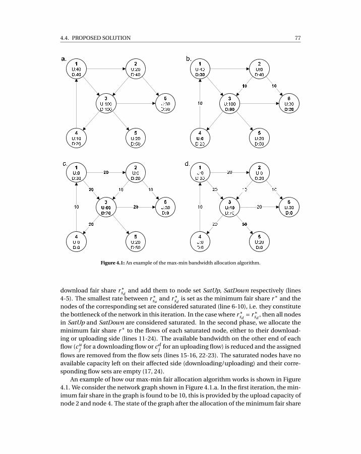
4.4. PROPOSED SOLUTION 77
Figure 4.1: An example of the max-min bandwidth allocation algorithm.
download fair share r∗sd
and add them to node set SatUp, SatDown respectively (lines4-5). The smallest rate between r∗
suand r∗
sdis set as the minimum fair share r∗ and the
nodes of the corresponding set are considered saturated (line 6-10), i.e. they constitutethe bottleneck of the network in this iteration. In the case where r∗
sd= r∗
sd, then all nodes
in SatUp and SatDown are considered saturated. In the second phase, we allocate theminimum fair share r∗ to the flows of each saturated node, either to their download-ing or uploading side (lines 11-24). The available bandwidth on the other end of eachflow (cu
j for a downloading flow or cdj for an uploading flow) is reduced and the assigned
flows are removed from the flow sets (lines 15-16, 22-23). The saturated nodes have noavailable capacity left on their affected side (downloading/uploading) and their corre-sponding flow sets are empty (17, 24).
An example of how our max-min fair allocation algorithm works is shown in Figure4.1. We consider the network graph shown in Figure 4.1.a. In the first iteration, the min-imum fair share in the graph is found to be 10, this is provided by the upload capacity ofnode 2 and node 4. The state of the graph after the allocation of the minimum fair share
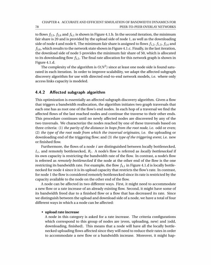
78
CHAPTER 4. ACCURATE AND EFFICIENT SIMULATION OF BANDWIDTH DYNAMICS FOR
PEER-TO-PEER OVERLAY NETWORKS
to flows f2,3, f2,6 and f4,1 is shown in Figure 4.1.b. In the second iteration, the minimumfair share is 20 and is provided by the upload side of node 1, as well as the downloadingside of node 4 and node 6. The minimum fair share is assigned to flows f1,2, f1,3, f3,4 andf3,6, which results to the network state shown in Figure 4.1.c. Finally, in the last iteration,the download side of node 5 provides the minimum fair share of 50, which is allocatedto its downloading flow f3,5. The final rate allocation for this network graph is shown inFigure 4.1.d.
The complexity of the algorithm is O(N 2) since at least one node side is found satu-rated in each iteration. In order to improve scalability, we adapt the affected subgraphdiscovery algorithm for use with directed end-to-end network models, i.e. where onlyaccess links capacity is modeled.
4.4.2 Affected subgraph algorithmThis optimization is essentially an affected subgraph discovery algorithm. Given a flowthat triggers a bandwidth reallocation, the algorithm initiates two graph traversals thateach one has as root one of the flow’s end nodes. In each hop of a traversal we find theaffected flows of the last reached nodes and continue the traverse to their other ends.This procedure continues until no newly affected nodes are discovered by any of thetwo traversals. We characterize the nodes reached by one of these traversals based onthree criteria: (1) the parity of the distance in hops from the root node, i.e. odd or even;(2) the type of the root node from which the traversal originates, i.e. the uploading ordownloading end of the triggering flow; and (3) the type of the triggering event, i.e. newor finished flow.
Furthermore, the flows of a node i are distinguished between locally bottlenecked,Li , and remotely bottlenecked, Ri . A node’s flow is referred as locally bottlenecked ifits own capacity is restricting the bandwidth rate of the flow. In contrast, a node’s flowis referred as remotely bottlenecked if the node at the other end of the flow is the onerestricting its bandwidth rate. For example, the flow f4,1 in Figure 4.1.d is locally bottle-necked for node 4 since it is its upload capacity that restricts the flow’s rate. In contrast,for node 1 the flow is considered remotely bottlenecked since its rate is restricted by thecapacity available to the node on the other end of the flow.
A node can be affected in two different ways. First, it might need to accommodatea new flow or a rate increase of an already existing flow. Second, it might have some ofits bandwidth freed due to a finished flow or a flow that has decreased its rate. Sincewe distinguish between the upload and download side of a node, we have a total of fourdifferent ways in which a a node can be affected:
• upload rate increaseA node in this category is asked for a rate increase. The criteria configurationswhich correspond to this group of nodes are {even, uploading, new} and {odd,downloading, finished}. This means that a node will have all the locally bottle-necked uploading flows affected since they will need to reduce their rates in orderto accommodate a new flow or a bandwidth increase. Moreover, it might hap-

4.4. PROPOSED SOLUTION 79
Algorithm 2 Directed affected subgraph algorithm
Input: A set of nodes U with their upload and download capacities cui ,cd
i ∀i ∈U , their
flow sets F ui , F d
i and a triggering flow fr1,r2 .Output: The subsets AU and AF of U and F respectively, that correspond to the affected
network subgraph.begin
1: hop ← 0; AU ←;; AF ←;2: if fr1,r2 ∈ F then3: AF ← AF ∪ { fr1,r2 }4: end if5: S AU ← {r1}; D AU ← {r2}6: while S AU 6= D AU 6= ; do7: AU ← AU ∪S AU ∪D AU8: S AU ′ ←;; D AU ′ ←;9: for all i ∈ S AU do
10: if (hop mod 2 6= 0 and fr1,r2 ∈ F ) or (step mod 2 == 0 and fr1,r2 ∉ F ) then11: S AU ′ ← S AU ′∪DownDecr ease(i )12: else if (hop mod 2 6= 0 and fr1,r2 ∉ F ) or (hop mod 2 == 0 and fr1,r2 ∈ F ) then13: S AU ′ ← S AU ′∪DownIncr ease(i )14: end if15: end for16: for all i ∈ D AU do17: if (hop mod 2 6= 0 and fr1,r2 ∈ F ) or (hop mod 2 == 0 and fr1,r2 ∉ F ) then18: D AU ′ ← D AU ′∪UpDecr ease(i )19: else if (hop mod 2 6= 0 and fr1,r2 ∉ F ) or (hop mod 2 == 0 and fr1,r2 ∈ F ) then20: D AU ′ ← D AU ′∪UpIncr ease(i )21: end if22: end for23: S AU ← S AU ′; D AU ← D AU ′24: hop ← hop +125: end whileend
Algorithm 3 "UpDecrease(node)" returns the nodes reached by means of locally bottle-necked uploading flows.
1: procedure UpDecrease(A node i ) ⟨The set of nodes reached by the affected locallybottlenecked uploading flows of i ⟩
2: AF ← AF ∪ { fi j | fi j ∈ F ui and fi j ∈ Lu
i }3: return { j | fi j ∈ F u
i and j unaffected by download increase and fi j ∈ Lui }
4: end procedure

80
CHAPTER 4. ACCURATE AND EFFICIENT SIMULATION OF BANDWIDTH DYNAMICS FOR
PEER-TO-PEER OVERLAY NETWORKS
Algorithm 4 "UpIncrease(node)" returns the nodes reached by means of locally and re-motely bottlenecked uploading flows.
1: procedure UpIncrease(A node i ) ⟨The set of nodes reached by affected locally andremotely bottlenecked uploading flows of i ⟩
2: AF ← AF ∪ { fi j | fi j ∈ F ui and ( fi j ∈ Lu
i or ( fi j ∈ Rui and (4.1) false for ri j ))}
3: return { j | fi j ∈ F ui and j unaffected by download decrease and ( fi j ∈ Lu
i or ( fi j ∈Ru
i and (4.1) false for ri j ))}4: end procedure
pen that some or all of the remotely bottlenecked outgoing flows might turn intolocally bottlenecked. We can find the remotely affected bottlenecked flows of anode x by evaluating the following expression, as proposed by [22]:
A : ri <cu
x −∑i−1j=1 r j
|F ux |− i +1
, i ∈ |Rux |, (4.1)
cux is the upload capacity of x, and ri , where i ∈ Ru
x , the rate of a remotely bot-tlenecked uploading flow i of x. We consider the remotely bottlenecked flows or-dered by increasing rate size: r1 ≤ r2 ≤ ·· · ≤ r|Ru
x |. The above condition is evaluatedstarting from i = 1 until it is either true for all i ∈ Ru
x or becomes false for a certaini . In the first case all remotely bottlenecked flows remain unaffected. In the sec-ond case the flows with rates ri ,ri+1, ...,r|Ru
x | might turn into locally bottleneckedby the rate increase and thus should be considered as affected.
• upload rate decreaseThe nodes included in this category got affected due to a rate decrease of one oftheir uploading flows. The criteria configurations for these nodes are {odd, down-loading, new} and {even, uploading, finished}. Nodes falling into this categoryneed to allocate a released amount of upload/download bandwidth to their cur-rently active flows. This leads all their locally bottlenecked outgoing flows to beaffected by the operation.
• download rate increaseThese nodes are affected by a rate increase in the same manner as the ones inthe first category but by means of a downloading flow. The criteria configurationscorresponding to this node category are {even, downloading, new} and {odd, up-loading, finished}.
• download rate decreaseLike the nodes of the second category, these nodes experience a rate decrease butthis time caused by a downloading flow. The criteria configurations which repre-sent this category are {odd, uploading, new} and {even, downloading, finished}.
During the same round of affected subgraph discovery, a node side can be reachedboth by a request to increase and by a request to decrease its flow rates. This makes
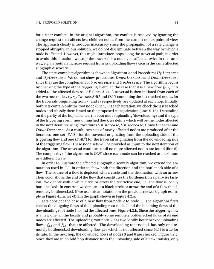
4.4. PROPOSED SOLUTION 81
for a clear conflict. In the original algorithm, the conflict is resolved by ignoring thechange request that affects less children nodes from the current node’s point of view.The approach clearly introduces inaccuracy since the propagation of a rate change isstopped abruptly. In our solution, we do not discriminate between the way by which anode is affected. However, this might introduce loops along the traversal path, in orderto avoid this situation, we stop the traversal if a node gets affected twice in the sameway, e.g. if it gets an increase request from its uploading flows twice in the same affectedsubgraph discovery.
The state-complete algorithm is shown in Algorithm 2 and Procedures UpIncr easeand UpDecr ease. We do not show procedures DownIncr ease and DownDecr easesince they are the complement of UpIncr ease and UpDecr ease. The algorithm beginsby checking the type of the triggering event. In the case that it is a new flow fr1,r2 , it isadded to the affected flow set AF (lines 3-4). A traversal is then initiated from each ofthe two root nodes, r1,r2. Two sets S AU and D AU containing the last reached nodes, forthe traversals originating from r1 and r2 respectively, are updated at each hop. Initially,both sets contain only the root node (line 5). At each iteration, we check the last reachednodes and classify them based on the proposed categorization (lines 9-18). Dependingon the parity of the hop distance, the root node (uploading/downloading) and the typeof the triggering event (new or finished flow), we define which will be the nodes affectedin the next iteration using Procedures UpIncr ease, UpDecr ease, DownIncr ease andDownDecr ease. As a result, two sets of newly affected nodes are produced after theiteration: one set (S AU ′) for the traversal originating from the uploading side of thetriggering flow and one (D AU ′) for the traversal originating from the downloading sideof the triggering flow. These node sets will be provided as input to the next iteration ofthe algorithm. The traversal continues until no more affected nodes are found (line 6).The complexity of the algorithm is O(N ) since each node can be reached at maximumin 4 different ways.
In order to illustrate the affected subgraph discovery algorithm, we extend the an-notation used in [22] in order to show both the direction and the bottleneck side of aflow. The source of a flow is depicted with a circle and the destination with an arrow.Their color shows the end of the flow that constitutes the bottleneck on a pairwise fash-ion. We denote with a white circle or arrow the restrictive end, i.e. the flow is locallybottlenecked. In contrast, we denote as a black circle or arrow the end of a flow that isremotely bottlenecked. If we use this annotation on the previous network graph exam-ple in Figure 4.1.a, we obtain the graph shown in Figure 4.2.a.
Lets consider the case of a new flow from node 2 to node 1. The algorithm firstschecks the outgoing flows of the uploading root node 2 and the incoming flows of thedownloading root node 1 to find the affected ones, Figure 4.2.b. Since the triggering flowis a new one, all the locally and probably some remotely bottlenecked flows of its endnodes are affected. The uploading root node 2 has two locally bottlenecked uploadingflows, f2,3 and f2,6, that are affected. The downloading root node 1 has only one re-motely bottlenecked downloading flow f4,1 which is not affected since (4.1) is true forits rate. In the next hop, the download flows of nodes 3 and 6 are checked, Figure 4.2.c.Since they are in an odd hop distance from the uploading side of a new transfer, only
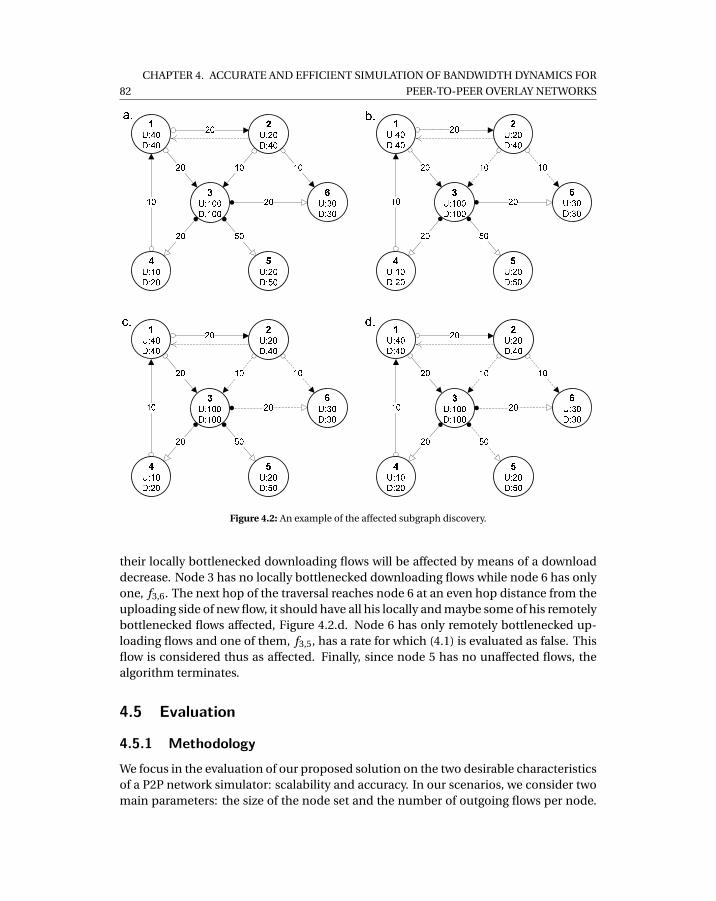
82
CHAPTER 4. ACCURATE AND EFFICIENT SIMULATION OF BANDWIDTH DYNAMICS FOR
PEER-TO-PEER OVERLAY NETWORKS
Figure 4.2: An example of the affected subgraph discovery.
their locally bottlenecked downloading flows will be affected by means of a downloaddecrease. Node 3 has no locally bottlenecked downloading flows while node 6 has onlyone, f3,6. The next hop of the traversal reaches node 6 at an even hop distance from theuploading side of new flow, it should have all his locally and maybe some of his remotelybottlenecked flows affected, Figure 4.2.d. Node 6 has only remotely bottlenecked up-loading flows and one of them, f3,5, has a rate for which (4.1) is evaluated as false. Thisflow is considered thus as affected. Finally, since node 5 has no unaffected flows, thealgorithm terminates.
4.5 Evaluation
4.5.1 MethodologyWe focus in the evaluation of our proposed solution on the two desirable characteristicsof a P2P network simulator: scalability and accuracy. In our scenarios, we consider twomain parameters: the size of the node set and the number of outgoing flows per node.
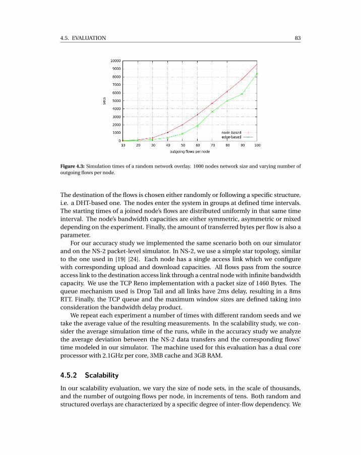
4.5. EVALUATION 83
Figure 4.3: Simulation times of a random network overlay. 1000 nodes network size and varying number ofoutgoing flows per node.
The destination of the flows is chosen either randomly or following a specific structure,i.e. a DHT-based one. The nodes enter the system in groups at defined time intervals.The starting times of a joined node’s flows are distributed uniformly in that same timeinterval. The node’s bandwidth capacities are either symmetric, asymmetric or mixeddepending on the experiment. Finally, the amount of transferred bytes per flow is also aparameter.
For our accuracy study we implemented the same scenario both on our simulatorand on the NS-2 packet-level simulator. In NS-2, we use a simple star topology, similarto the one used in [19] [24]. Each node has a single access link which we configurewith corresponding upload and download capacities. All flows pass from the sourceaccess link to the destination access link through a central node with infinite bandwidthcapacity. We use the TCP Reno implementation with a packet size of 1460 Bytes. Thequeue mechanism used is Drop Tail and all links have 2ms delay, resulting in a 8msRTT. Finally, the TCP queue and the maximum window sizes are defined taking intoconsideration the bandwidth delay product.
We repeat each experiment a number of times with different random seeds and wetake the average value of the resulting measurements. In the scalability study, we con-sider the average simulation time of the runs, while in the accuracy study we analyzethe average deviation between the NS-2 data transfers and the corresponding flows’time modeled in our simulator. The machine used for this evaluation has a dual coreprocessor with 2.1GHz per core, 3MB cache and 3GB RAM.
4.5.2 ScalabilityIn our scalability evaluation, we vary the size of node sets, in the scale of thousands,and the number of outgoing flows per node, in increments of tens. Both random andstructured overlays are characterized by a specific degree of inter-flow dependency. We
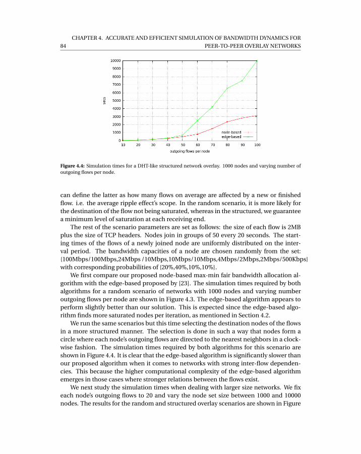
84
CHAPTER 4. ACCURATE AND EFFICIENT SIMULATION OF BANDWIDTH DYNAMICS FOR
PEER-TO-PEER OVERLAY NETWORKS
Figure 4.4: Simulation times for a DHT-like structured network overlay. 1000 nodes and varying number ofoutgoing flows per node.
can define the latter as how many flows on average are affected by a new or finishedflow. i.e. the average ripple effect’s scope. In the random scenario, it is more likely forthe destination of the flow not being saturated, whereas in the structured, we guaranteea minimum level of saturation at each receiving end.
The rest of the scenario parameters are set as follows: the size of each flow is 2MBplus the size of TCP headers. Nodes join in groups of 50 every 20 seconds. The start-ing times of the flows of a newly joined node are uniformly distributed on the inter-val period. The bandwidth capacities of a node are chosen randomly from the set:{100Mbps/100Mbps,24Mbps /10Mbps,10Mbps/10Mbps,4Mbps/2Mbps,2Mbps/500Kbps}with corresponding probabilities of {20%,40%,10%,10%}.
We first compare our proposed node-based max-min fair bandwidth allocation al-gorithm with the edge-based proposed by [23]. The simulation times required by bothalgorithms for a random scenario of networks with 1000 nodes and varying numberoutgoing flows per node are shown in Figure 4.3. The edge-based algorithm appears toperform slightly better than our solution. This is expected since the edge-based algo-rithm finds more saturated nodes per iteration, as mentioned in Section 4.2.
We run the same scenarios but this time selecting the destination nodes of the flowsin a more structured manner. The selection is done in such a way that nodes form acircle where each node’s outgoing flows are directed to the nearest neighbors in a clock-wise fashion. The simulation times required by both algorithms for this scenario areshown in Figure 4.4. It is clear that the edge-based algorithm is significantly slower thanour proposed algorithm when it comes to networks with strong inter-flow dependen-cies. This because the higher computational complexity of the edge-based algorithmemerges in those cases where stronger relations between the flows exist.
We next study the simulation times when dealing with larger size networks. We fixeach node’s outgoing flows to 20 and vary the node set size between 1000 and 10000nodes. The results for the random and structured overlay scenarios are shown in Figure
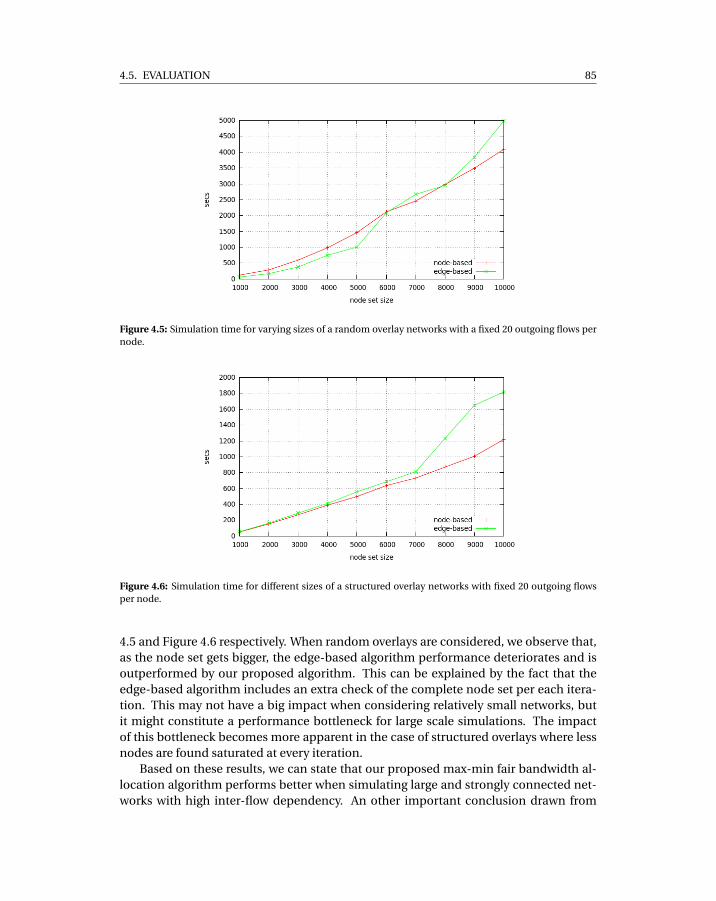
4.5. EVALUATION 85
Figure 4.5: Simulation time for varying sizes of a random overlay networks with a fixed 20 outgoing flows pernode.
Figure 4.6: Simulation time for different sizes of a structured overlay networks with fixed 20 outgoing flowsper node.
4.5 and Figure 4.6 respectively. When random overlays are considered, we observe that,as the node set gets bigger, the edge-based algorithm performance deteriorates and isoutperformed by our proposed algorithm. This can be explained by the fact that theedge-based algorithm includes an extra check of the complete node set per each itera-tion. This may not have a big impact when considering relatively small networks, butit might constitute a performance bottleneck for large scale simulations. The impactof this bottleneck becomes more apparent in the case of structured overlays where lessnodes are found saturated at every iteration.
Based on these results, we can state that our proposed max-min fair bandwidth al-location algorithm performs better when simulating large and strongly connected net-works with high inter-flow dependency. An other important conclusion drawn from
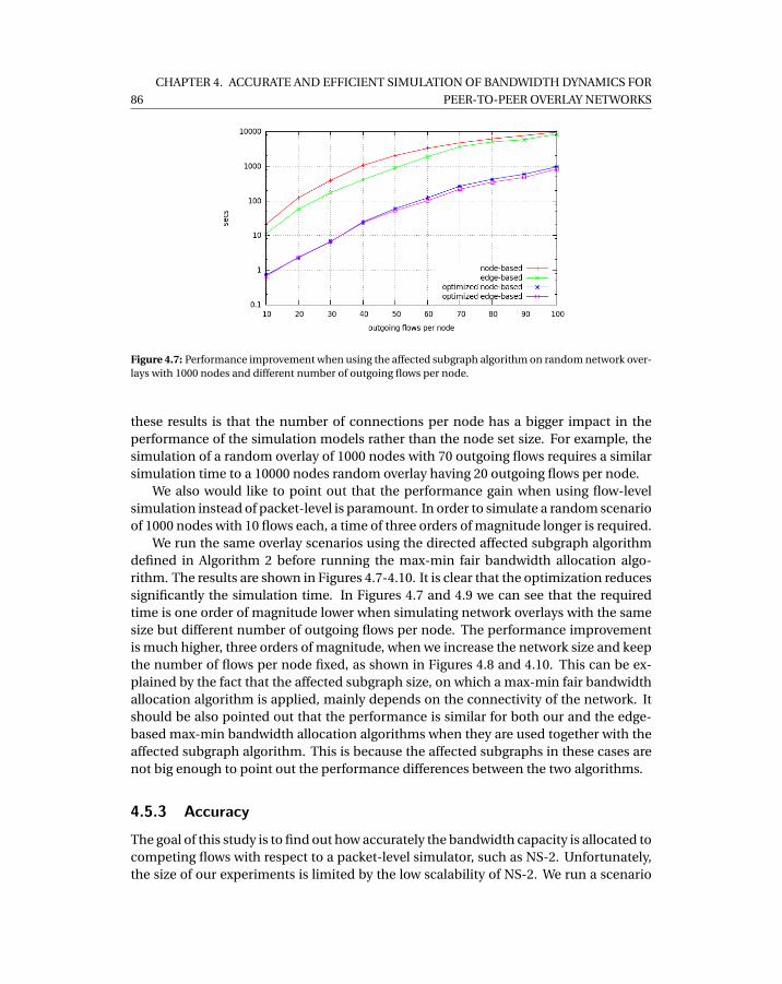
86
CHAPTER 4. ACCURATE AND EFFICIENT SIMULATION OF BANDWIDTH DYNAMICS FOR
PEER-TO-PEER OVERLAY NETWORKS
Figure 4.7: Performance improvement when using the affected subgraph algorithm on random network over-lays with 1000 nodes and different number of outgoing flows per node.
these results is that the number of connections per node has a bigger impact in theperformance of the simulation models rather than the node set size. For example, thesimulation of a random overlay of 1000 nodes with 70 outgoing flows requires a similarsimulation time to a 10000 nodes random overlay having 20 outgoing flows per node.
We also would like to point out that the performance gain when using flow-levelsimulation instead of packet-level is paramount. In order to simulate a random scenarioof 1000 nodes with 10 flows each, a time of three orders of magnitude longer is required.
We run the same overlay scenarios using the directed affected subgraph algorithmdefined in Algorithm 2 before running the max-min fair bandwidth allocation algo-rithm. The results are shown in Figures 4.7-4.10. It is clear that the optimization reducessignificantly the simulation time. In Figures 4.7 and 4.9 we can see that the requiredtime is one order of magnitude lower when simulating network overlays with the samesize but different number of outgoing flows per node. The performance improvementis much higher, three orders of magnitude, when we increase the network size and keepthe number of flows per node fixed, as shown in Figures 4.8 and 4.10. This can be ex-plained by the fact that the affected subgraph size, on which a max-min fair bandwidthallocation algorithm is applied, mainly depends on the connectivity of the network. Itshould be also pointed out that the performance is similar for both our and the edge-based max-min bandwidth allocation algorithms when they are used together with theaffected subgraph algorithm. This is because the affected subgraphs in these cases arenot big enough to point out the performance differences between the two algorithms.
4.5.3 AccuracyThe goal of this study is to find out how accurately the bandwidth capacity is allocated tocompeting flows with respect to a packet-level simulator, such as NS-2. Unfortunately,the size of our experiments is limited by the low scalability of NS-2. We run a scenario
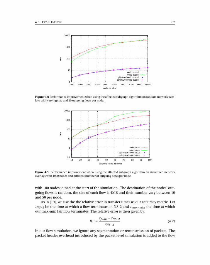
4.5. EVALUATION 87
Figure 4.8: Performance improvement when using the affected subgraph algorithm on random network over-lays with varying size and 20 outgoing flows per node.
Figure 4.9: Performance improvement when using the affected subgraph algorithm on structured networkoverlays with 1000 nodes and different number of outgoing flows per node.
with 100 nodes joined at the start of the simulation. The destination of the nodes’ out-going flows is random, the size of each flow is 4MB and their number vary between 10and 50 per node.
As in [19], we use the the relative error in transfer times as our accuracy metric. LettN S−2 be the time at which a flow terminates in NS-2 and tmax−mi n the time at whichour max-min fair flow terminates. The relative error is then given by:
RE = t f low − tN S−2
tN S−2(4.2)
In our flow simulation, we ignore any segmentation or retransmission of packets. Thepacket header overhead introduced by the packet level simulation is added to the flow
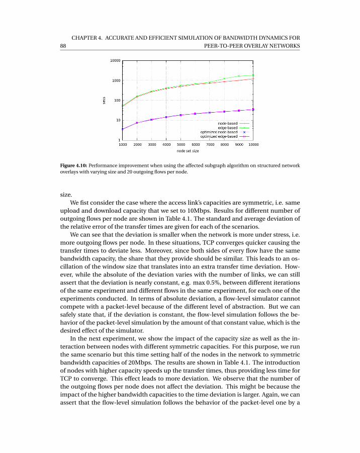
88
CHAPTER 4. ACCURATE AND EFFICIENT SIMULATION OF BANDWIDTH DYNAMICS FOR
PEER-TO-PEER OVERLAY NETWORKS
Figure 4.10: Performance improvement when using the affected subgraph algorithm on structured networkoverlays with varying size and 20 outgoing flows per node.
size.We fist consider the case where the access link’s capacities are symmetric, i.e. same
upload and download capacity that we set to 10Mbps. Results for different number ofoutgoing flows per node are shown in Table 4.1. The standard and average deviation ofthe relative error of the transfer times are given for each of the scenarios.
We can see that the deviation is smaller when the network is more under stress, i.e.more outgoing flows per node. In these situations, TCP converges quicker causing thetransfer times to deviate less. Moreover, since both sides of every flow have the samebandwidth capacity, the share that they provide should be similar. This leads to an os-cillation of the window size that translates into an extra transfer time deviation. How-ever, while the absolute of the deviation varies with the number of links, we can stillassert that the deviation is nearly constant, e.g. max 0.5%, between different iterationsof the same experiment and different flows in the same experiment, for each one of theexperiments conducted. In terms of absolute deviation, a flow-level simulator cannotcompete with a packet-level because of the different level of abstraction. But we cansafely state that, if the deviation is constant, the flow-level simulation follows the be-havior of the packet-level simulation by the amount of that constant value, which is thedesired effect of the simulator.
In the next experiment, we show the impact of the capacity size as well as the in-teraction between nodes with different symmetric capacities. For this purpose, we runthe same scenario but this time setting half of the nodes in the network to symmetricbandwidth capacities of 20Mbps. The results are shown in Table 4.1. The introductionof nodes with higher capacity speeds up the transfer times, thus providing less time forTCP to converge. This effect leads to more deviation. We observe that the number ofthe outgoing flows per node does not affect the deviation. This might be because theimpact of the higher bandwidth capacities to the time deviation is larger. Again, we canassert that the flow-level simulation follows the behavior of the packet-level one by a

4.6. CONCLUSION & FUTURE WORK 89
cu/cd flows std. deviation avg. deviation
10/10
10 9.6±0.6% 7.9±0.6%20 7.3±0.3% 5.9±0.2%30 6.1±0.3% 5±0.2%40 5.1±0.3% 4±0.3%50 4.4±0.2% 3.6±0.2%
10/10, 20/20
10 12.7±1.0% 10.5±0.9%20 13.7±0.4% 11.3±0.4%30 12.6±0.3% 10.8±0.4%40 13.1±0.4% 11.4±0.5%50 13.2±0.3% 11.5±0.4%
Table 4.1: Deviation of transfer times.
nearly constant degree.Next we consider the case of asymmetric bandwidth capacities. We assign to every
node 20Mbps of download capacity and 10Mbps of upload capacity. The results fordifferent number of outgoing flows per node are shown in Table 4.2. It appears thatthe deviation is significantly smaller and not affected by the per node outgoing flowscomparing to the previous symmetric scenario. This can be explained by the absence ofoscillation and quicker TCP convergence due to the larger download capacity.
Finally, we investigate the deviation when both symmetric and asymmetric nodecapacities are used. We set half of the nodes with a symmetric 10Mbps capacity and therest with asymmetric capacity of 20Mbps download and 10Mbps upload. The resultsare also given in Table 4.2. We can see that the presence of the symmetric capacitiesaffects negatively the transfer time deviation. The negative impact is more visible whenfewer outgoing flows per node are used. When the links are less congested, the slowerconvergence of the flow rates of the nodes with smaller symmetric capacities is moreapparent.
In the last two experiments, as in the first two, we measured a deviation from theNS-2 packet-level simulation but our max-min fair simulation followed the trends ofthe ones provided by NS-2 by an almost constant deviation factor.
4.6 Conclusion & Future Work
In this paper we presented a scalable and efficient flow-level network simulation modelbased on the max-min fairness idea. We evaluated our solution in terms of scalability byshowing that it outperforms the existing state-of-the-art for large-scale and structurednetwork overlays where a directed network is used for the modeling. In terms of accu-racy we showed that our approach follows the trends of the NS-2 packet-level simulatornetwork by a nearly constant factor throughout the experiments.
Our ongoing work includes the improvement of the model’s accuracy by consideringthe time period that a flow requires to converge to a new rate, and also the use of time-

90
CHAPTER 4. ACCURATE AND EFFICIENT SIMULATION OF BANDWIDTH DYNAMICS FOR
PEER-TO-PEER OVERLAY NETWORKS
cu/cd flows std. deviation avg. deviation
20/10
10 3.8±0.4% 3±0.4%20 3.9±0.2% 3.1±0.1%30 4.1±0.3% 3.3±0.2%40 3.4±0.2% 2.8±0.2%50 3±0.1% 2.5±0.2%
20/10,10/10
10 6.4±0.4% 5±0.4%20 6±0.4% 4.9±0.3%30 4.8±0.4% 3.9±0.3%40 3.4±0.9% 3.2±0.3%50 3.5±0.2% 2.8±0.2%
Table 4.2: Deviation of transfer times in the presence of asymmetric node capacities.
stepping aggregation to achieve higher performance with minimum cost in accuracy.
4.7 References
[1] Anwar Al Hamra, Arnaud Legout, and Chadi Barakat. Understanding the proper-ties of the bittorrent overlay. Technical report, INRIA, 2007.
[2] Chuan Wu, Baochun Li, and Shuqiao Zhao. Magellan: Charting large-scale peer-to-peer live streaming topologies. In ICDCS ’07: Proceedings of the 27th Interna-tional Conference on Distributed Computing Systems, page 62, Washington, DC,USA, 2007. IEEE Computer Society.
[3] Guillaume Urvoy-Keller and Pietro Michiardi. Impact of inner parameters andoverlay structure on the performance of bittorrent. In INFOCOM ’06: Proceedingsof the 25th Conference on Computer Communications, 2006.
[4] B. Cohen. Incentives Build Robustness in BitTorrent. In Econ ’04: Proceedings ofthe Workshop on Economics of Peer-to-Peer Systems, Berkley, CA, USA, June 2003.
[5] S. Naicken, B. Livingston, A. Basu, S. Rodhetbhai, I. Wakeman, and D. Chalmers.The state of peer-to-peer simulators and simulations. SIGCOMM Computer Com-munication Review, 37(2):95–98, 2007.
[6] Ingmar Baumgart, Bernhard Heep, and Stephan Krause. Oversim: A flexible over-lay network simulation framework. In GI ’07: Proceedings of 10th IEEE Global In-ternet Symposium, pages 79–84, Anchorage, AL, USA, May 2007.
[7] Sam Joseph. An extendible open source p2p simulator. P2P Journal, 0:1–15, 2003.
[8] Jordi Pujol-Ahullo, Pedro Garcia-Lopez, Marc Sanchez-Artigas, and Marcel Arrufat-Arias. An extensible simulation tool for overlay networks and services. In SAC ’09:
4.7. REFERENCES 91
Proceedings of the 24th ACM Symposium on Applied Computing, pages 2072–2076,New York, NY, USA, March 2009. ACM.
[9] Alberto Montresor Mark Jelasity and Ozalp Babaoglu. A modular paradigm forbuilding self-organizing peer-to-peer applications. In Engineering Self-OrganisingSystems, pages 265–282, 2003.
[10] Nyik San Ting and Ralph Deters. 3ls - a peer-to-peer network simulator. In P2P ’03:Proceedings of the 3rd International Conference on Peer-to-Peer Computing, page212. IEEE Computer Society, August 2003.
[11] David M. Nicol, Jason Liu, Michael Liljenstam, and Guanhua Yan. Simulation oflarge scale networks i: simulation of large-scale networks using ssf. In WSC ’03:Proceedings of the 35th Conference on Winter simulation, pages 650–657. WinterSimulation Conference, December 2003.
[12] Andras Varga and Rudolf Hornig. An overview of the omnet++ simulation environ-ment. In Simutools ’08: Proceedings of the 1st International Conference on Simu-lation Tools and Techniques for Communications, Networks and Systems & Work-shops, pages 1–10, Brussels, Belgium, Belgium, 2008. ICST (Institute for ComputerSciences, Social-Informatics and Telecommunications Engineering).
[13] The network simulator ns-2. http://www.isi.edu/nsnam/ns/, October 2010.
[14] Thomer M. Gil, Frans Kaashoek, Jinyang Li, Robert Morris, and JeremyStribling. p2psim: a simulator for peer-to-peer (p2p) protocols.http://pdos.csail.mit.edu/p2psim/, October 2006.
[15] Wu Kun, Dai Han, Yang Zhang, Sanglu Lu, Daoxu Chen, , and Li Xie. Ndp2psim: Ans2-based platform for peer-to-peer network simulations. In ISPA ’05: Proceedingsof Parallel and Distributed Processing and Applications, Workshops, volume 3759,pages 520–529. Springer Berlin / Heidelberg, November 2005.
[16] G. Kesidis, A. Singh, D. Cheung, and W.W. Kwok. Feasibility of fluid event-drivensimulation for atm networks. In GLOBECOM ’96: Proceedings of the Global Com-munications Conference, volume 3, pages 2013 –2017, November 1996.
[17] Daniel R. Figueiredo, Benyuan Liu, Yang Guo, James F. Kurose, and Donald F.Towsley. On the efficiency of fluid simulation of networks. Computer Networks,50(12):1974–1994, 2006.
[18] Dimitri Bertsekas and Robert Gallager. Data Networks. Prentice Hall, second edi-tion, 1992.
[19] Abdulhalim Dandoush and Alain Jean-Marie. Flow-level modeling of paralleldownload in distributed systems. In CTRQ ’10: Third International Conference onCommunication Theory, Reliability, and Quality of Service, pages 92 –97, 2010.
92
CHAPTER 4. ACCURATE AND EFFICIENT SIMULATION OF BANDWIDTH DYNAMICS FOR
PEER-TO-PEER OVERLAY NETWORKS
[20] W. Yang and N Abu-Ghazaleh. Gps: a general peer-to-peer simulator and its usefor modeling bittorrent. In MASCOTS ’05: Proceedings of 13th IEEE InternationalSymposium on Modeling, Analysis, and Simulation of Computer and Telecommu-nication Systems, pages 425–432, Atlanta, Georgia, USA, September 2005.
[21] Thomas J. Giuli and Mary Baker. Narses: A scalable flow-based network simulator.Computing Research Repository, cs.PF/0211024, 2002.
[22] F. Lo Piccolo, G. Bianchi, and S. Cassella. Efficient simulation of bandwidth alloca-tion dynamics in p2p networks. In GLOBECOM ’06: Proceedings of the 49th GlobalTelecommunications Conference, pages 1–6, San Franscisco, California, November2006.
[23] Anh Tuan Nguyen and F. Eliassen. An efficient solution for max-min fair rate allo-cation in p2p simulation. In ICUMT ’09: Proceedings of the International Confer-ence on Ultra Modern Telecommunications Workshops, pages 1 –5, St. Petersburg,Russia, October 2009.
[24] Tobias Hossfeld, Andreas Binzenhofer, Daniel Schlosser, Kolja Eger, Jens Oberen-der, Ivan Dedinski, and Gerald Kunzmann. Towards efficient simulation of largescale p2p networks. Technical Report 371, University of Wurzburg, Institute ofComputer Science, Am Hubland, 97074 Wurzburg, Germany, October 2005.

PART III
Network Layer
93


CH
AP
TE
R
5NATCRACKER: NAT COMBINATIONS
MATTER

5.1. INTRODUCTION 97
NATCracker: NAT Combinations Matter
Roberto Roverso1,2, Sameh El-Ansary1 and Seif Haridi2
1Peerialism ABStockholm, Sweden
[roberto,sameh]@peerialism.com
2KTH - Royal Institute of TechnologyStockholm, Sweden[haridi]@kth.se
Abstract
In this paper, we report our experience in working with Network Address Trans-lators (NATs). Traditionally, there were only 4 types of NATs. For each type, the(im)possibility of traversal is well-known. Recently, the NAT community has pro-vided a deeper dissection of NAT behaviors resulting into at least 27 types and doc-umented the (im)possibility of traversal for some types. There are, however, twofundamental issues that were not previously tackled by the community. First, giventhe more elaborate set of behaviors, it is incorrect to reason about traversing a singleNAT, instead combinations must be considered and we have not found any studythat comprehensively states, for every possible combination, whether direct con-nectivity with no relay is feasible. Such a statement is the first outcome of the pa-per. Second, there is a serious need for some kind of formalism to reason aboutNATs which is a second outcome of this paper. The results were obtained using ourown scheme which is an augmentation of currently-known traversal methods. Thescheme is validated by reasoning using our formalism, simulation and implemen-tation in a real P2P network.
5.1 Introduction
Dealing with Network Address Translators (NATs) is nowadays an essential need for anyP2P application. The techniques used to deal with NAT have been more or less “coined”and there are several widely-used methods[1][2]. Some of them are rather a defactostandard like STUN [3],TURN [4],ICE [5].
98 CHAPTER 5. NATCRACKER: NAT COMBINATIONS MATTER
In the context of our a P2P live video streaming application PeerTV, we are mainlyconcerned with media streaming using UDP and therefore the scope of this paper isUDP NAT traversal. Moreover, we are strictly interested in solutions that do not userelay, such as TURN for instance, due to the high bandwidth requirements of videostreaming.
We have found lots of of previous work on the subject that aims to answer the follow-ing question: For every t in the set of NAT types T , which s in the set of traversal strategiesS should be used to traverse t? The answer is of the form f : mathcalT →S . i.e. the fol-lowing is an example with a couple of types f : { Simple Hole Punching, Port-Prediction} → { Full-Cone, Symmetric} [6].
However, the point which we found not gaining enough attention is that the pres-ence of a feasible traversal technique that enables two peers behind NAT to communi-cate depends on the “combination” of the NAT types and not on the type of each peerseparately. Thus, the question should be: “Given 2 peers pa and pb with respective NATtypes t (pa) and t (pb), which traversal strategy s is needed for p1 and p2 to talk? The an-swer is of the form f : T ×T → S ”, i.e we need to analyze traversable combinationsrather than traversable types.
Most works contain a few examples of combinations for explanation purposes [6][7].However, we have failed to find any comprehensive analysis that states, for every possi-ble combination of NAT types, whether direct (i.e. with no relay) connectivity is possi-ble and how. The analysis is more topical given that NAT community is switching fromthe classical set of NAT types Tcl assi c = { Full-Cone, Restricted-Cone, Port-Restricted,Symmetric} [3] to a more elaborate set that defines a NAT type by a combination of threedifferent policies, namely, port mapping, port allocation and port filtering [8]. With that,a statement like “two peers behind symmetric NAT can not communicate” becomes im-precise, as we will show that in many cases it is possible given the nuances available inthe presently wide spectrum of NAT types.
5.2 Related Work
The work in [7] includes a matrix for a number of combinations, however mostly drawnfrom Tcl assi c rather than the more elaborate classification in [8]. The work in [6] is prob-ably the closest to ours, one can see our work as a superset of the set of combinationsmentioned in that work.
5.3 NAT Types as Combinations of Policies
In this section we try to semi-formally summarize the more elaborate classification ofNATs known as “BEHAVE-compliant”[8] and craft the notation that we will use in therest of the paper.
Notation. Let na and nb be NAT gateways. For i ∈ {a,b}, Let Pi = {pi , p ′i , p ′′
i , . . . } bethe set of peers behind ni . An “endpoint” e is a host-port pair e = (h, p), where h(e)is the host of e and p(e) is its port. Let Vi = {vi , v ′
i , v ′′i , . . . } denote the set of all private

5.3. NAT TYPES AS COMBINATIONS OF POLICIES 99
endpoints of all peers behind ni and Ui = {ui ,u′i ,u′′
i . . . } be the set of public endpointsof ni . i.e ∀v ∈Vi ,h(v) ∈ Pi and ∀u : Ui ,h(u) = ni .
When a packet is sent out from a certain private endpoint vi of a peer pi behinda gateway ni , to some public endpoint d , a rule in the NAT table of ni is created. Wedefine the set of NAT table rules Ri = {ri ,r ′
i ,r ′′′i } at ni , the rule records the fact that some
public port ui and some private port vi are associated, e.g ra = (va ↔ ua).The behavior of a gateway ni is defined by three policies, namely, port mapping,
port filtering and port allocation. We use the notation f (ni ),m(ni ), a(ni ) to denote therespective policies of gateway ni .
5.3.1 Mapping PolicyThe mapping policy is triggered every time a packet is sent from a private endpoint vi
behind the NAT to some external public port d . The role of a mapping policy is decidingwhether a new rule will be added or an existing one will be reused. We use the notation:
1.−−−→vi ,d Í ri to specify that the sending of a packet from vi to d resulted in the cre-ation of a new NAT table rule ri at ni . That is the binding of a new public port onni . However, we say that a rule was created because we care not only about thebinding of the port but also the constraints on using this new port.
2.−−−→vi ,d ⇒ ri to specify that the sending of the packet reused an already existing ruleri .
3.−−−→vi ,d
r eason6=⇒ ri to specify that the sending of the packet did not reuse some ri inparticular because of some “reason”.
Irrespective of the mapping policy, whenever a packet is sent from a private port vi
to an arbitrary public destination endpoint d and Øri ∈ Ri of the form ri = (vi ↔ ui ),
for an arbitrary ui , the following is true−−−→vi ,d Í ri . However, if such a mapping exists,
the mapping policy would make the reuse decision based on the destination. For all
subsequent packets from vi to d , naturally,−−−→vi ,d ⇒ ri . However, for any d ′ 6= d , there are
3 different behaviors:
• Endpoint-Independent, m(ni ) = EI:−−−→vi ,d ′ ⇒ ri , for any d ′
• Host-Dependent, m(ni ) = HD:−−−→vi ,d ′ ⇒ ri , iff h(d) = h(d ′)−−−→vi ,d ′ Í r ′
i , iff h(d) 6= h(d ′), where r ′i = (vi ↔ u′
i )and u′
i 6= ui
• Port-Dependent, m(ni ) = PD:−−−→vi ,d ′ Í r ′
i

100 CHAPTER 5. NATCRACKER: NAT COMBINATIONS MATTER
Having introduced the different policies, we decorate the notation of the rule to includethe criteria that will be used to decide whether a certain rule will be reused as follows:
ri =
(vi ←−−−−−→
m:vi→∗ ui
)if m(ni ) = EI(
vi ←−−−−−−−−−→m:vi→(h(d),∗)
ui
)if m(ni ) = HD(
vi ←−−−−−→m:vi→d
ui
)if m(ni ) = PD
Where the syntax m : x → y means that the rule will be reused if the source endpoint ofthe packet is x and the destination is y . The ∗ denotes any endpoint.
Order. We impose the EI < HD < PD according to the increasing level of restrictive-ness.
5.3.2 Allocation Policy.Every time a new ri is added to Ri , a new public endpoint ui is bound. This policyallocates p(ui ). That is, the mapping policy decides when to bind a new port and theallocation policy decides which port should be bound as follows:
1. Port-Preservation, a(ni ) = PP:
Given−−−→vi ,d Í ri , where ri = (vi ↔ ui ), it is always the case that: p(ui ) = p(vi ).
Naturally, this may cause conflicts if any two pi and p ′i behind ni decided to bind
private endpoints with a common port.
2. Port Contiguity, a(ni ) = PC:Given any two sequentially allocated public endpoints ui and u′
i it is always thecase that: p(u′
i ) = p(ui )+∆, for some ∆= 1,2, ...
3. Random, a(ni ) = RD:∀ui , p(ui ) is allocated at random.
Order. We impose the order PP < PC < RD according to the increasing level of difficulty ofhandling.
5.3.3 Filtering Policy.The filtering policy decides whether a packet from the outside world to a public end-point of a NAT gateway should be forwarded to the corresponding private endpoint.Given an existing rule ri = (vi ↔ ui ) that was created to send a packet from vi to d , weuse the notation:
1. ri ⇐←−−ui , s to denote that the receival of a packet from the public endpoint s to ni ’spublic endpoint ui is permitted by ri
2. rir eason6⇐= ←−−ui , s to denote that the receival is not permitted because of some “reason”.
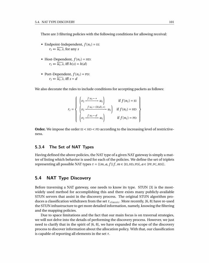
5.4. NAT TYPE DISCOVERY 101
There are 3 filtering policies with the following conditions for allowing receival:
• Endpoint-Independent, f (ni ) = EI:ri ⇐←−−ui , s, for any s
• Host-Dependent, f (ni ) = HD:ri ⇐←−−ui , s, iff h(s) = h(d)
• Port-Dependent, f (ni ) = PD:ri ⇐←−−ui , s, iff s = d
We also decorate the rules to include conditions for accepting packets as follows:
ri =
(vi
f :ui←∗←−−−−→ ui
)if f (ni ) = EI(
vif :ui←(h(d),∗)←−−−−−−−−−→ ui
)if f (ni ) = HD(
vif :ui←d←−−−−−→ ui
)if f (ni ) = PD
Order. We impose the order EI < HD < PD according to the increasing level of restrictive-ness.
5.3.4 The Set of NAT Types
Having defined the above policies, the NAT type of a given NAT gateway is simply a mat-ter of listing which behavior is used for each of the policies. We define the set of tripletsrepresenting all possible NAT types τ= {(m, a, f )| f ,m ∈ {EI, HD, PD}, a ∈ {PP, PC, RD}}.
5.4 NAT Type Discovery
Before traversing a NAT gateway, one needs to know its type. STUN [3] is the most-widely used method for accomplishing this and there exists many publicly-availableSTUN servers that assist in the discovery process. The original STUN algorithm pro-duces a classification withdrawn from the set τcl assi c . More recently, [6, 8] have re-usedthe STUN infrastructure to get more detailed information, namely, knowing the filteringand the mapping policies.
Due to space limitations and the fact that our main focus is on traversal strategies,we will not delve into the details of performing the discovery process. However, we justneed to clarify that in the spirit of [6, 8], we have expanded the scope of the discoveryprocess to discover information about the allocation policy. With that, our classificationis capable of reporting all elements in the set τ.
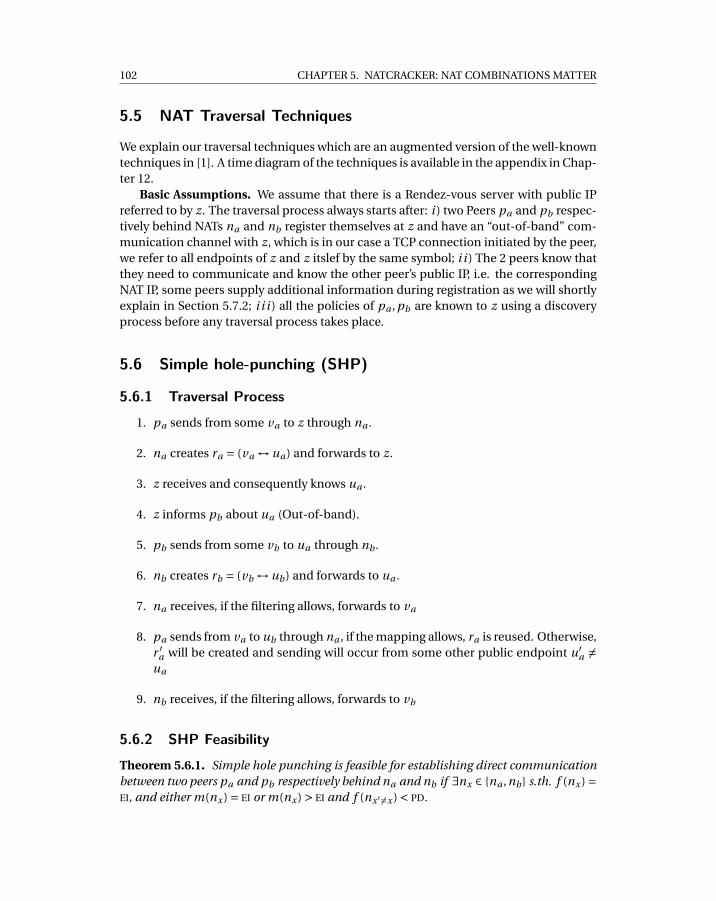
102 CHAPTER 5. NATCRACKER: NAT COMBINATIONS MATTER
5.5 NAT Traversal Techniques
We explain our traversal techniques which are an augmented version of the well-knowntechniques in [1]. A time diagram of the techniques is available in the appendix in Chap-ter 12.
Basic Assumptions. We assume that there is a Rendez-vous server with public IPreferred to by z. The traversal process always starts after: i ) two Peers pa and pb respec-tively behind NATs na and nb register themselves at z and have an “out-of-band” com-munication channel with z, which is in our case a TCP connection initiated by the peer,we refer to all endpoints of z and z itslef by the same symbol; i i ) The 2 peers know thatthey need to communicate and know the other peer’s public IP, i.e. the correspondingNAT IP, some peers supply additional information during registration as we will shortlyexplain in Section 5.7.2; i i i ) all the policies of pa , pb are known to z using a discoveryprocess before any traversal process takes place.
5.6 Simple hole-punching (SHP)
5.6.1 Traversal Process
1. pa sends from some va to z through na .
2. na creates ra = (va ↔ ua) and forwards to z.
3. z receives and consequently knows ua .
4. z informs pb about ua (Out-of-band).
5. pb sends from some vb to ua through nb .
6. nb creates rb = (vb ↔ ub) and forwards to ua .
7. na receives, if the filtering allows, forwards to va
8. pa sends from va to ub through na , if the mapping allows, ra is reused. Otherwise,r ′
a will be created and sending will occur from some other public endpoint u′a 6=
ua
9. nb receives, if the filtering allows, forwards to vb
5.6.2 SHP Feasibility
Theorem 5.6.1. Simple hole punching is feasible for establishing direct communicationbetween two peers pa and pb respectively behind na and nb if ∃nx ∈ {na ,nb} s.th. f (nx ) =EI, and either m(nx ) = EI or m(nx ) > EI and f (nx′ 6=x ) < PD.
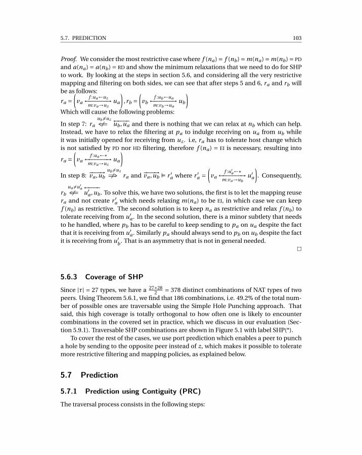
5.7. PREDICTION 103
Proof. We consider the most restrictive case where f (na) = f (nb) = m(na) = m(nb) = PD
and a(na) = a(nb) = RD and show the minimum relaxations that we need to do for SHPto work. By looking at the steps in section 5.6, and considering all the very restrictivemapping and filtering on both sides, we can see that after steps 5 and 6, ra and rb willbe as follows:
ra =(
vaf :ua←uz←−−−−−−→
m:va→uzua
),rb =
(vb
f :ub←ua←−−−−−−→m:vb→ua
ub
)Which will cause the following problems:
In step 7: ra
ub 6=uz6⇐= ←−−−−ub ,ua and there is nothing that we can relax at nb which can help.Instead, we have to relax the filtering at pa to indulge receiving on ua from ub whileit was initially opened for receiving from uz . i.e, ra has to tolerate host change whichis not satisfied by PD nor HD filtering, therefore f (na) = EI is necessary, resulting into
ra =(
vaf :ua←∗←−−−−−−→
m:va→uzua
)In step 8: −−−−→va ,ub
ub 6=uz6=⇒ ra and −−−−→va ,ub Í r ′a where r ′
a =(
vaf :u′
a←∗←−−−−−−→m:va→ub
u′a
). Consequently,
rb
ua 6=u′a6⇐= ←−−−−
u′a ,ub . To solve this, we have two solutions, the first is to let the mapping reuse
ra and not create r ′a which needs relaxing m(na) to be EI, in which case we can keep
f (nb) as restrictive. The second solution is to keep na as restrictive and relax f (nb) totolerate receiving from u′
a . In the second solution, there is a minor subtlety that needsto he handled, where pb has to be careful to keep sending to pa on ua despite the factthat it is receiving from u′
a . Similarly pa should always send to pb on ub despite the factit is receiving from u′
b . That is an asymmetry that is not in general needed.
5.6.3 Coverage of SHPSince |τ| = 27 types, we have a 27×28
2 = 378 distinct combinations of NAT types of twopeers. Using Theorem 5.6.1, we find that 186 combinations, i.e. 49.2% of the total num-ber of possible ones are traversable using the Simple Hole Punching approach. Thatsaid, this high coverage is totally orthogonal to how often one is likely to encountercombinations in the covered set in practice, which we discuss in our evaluation (Sec-tion 5.9.1). Traversable SHP combinations are shown in Figure 5.1 with label SHP(*).
To cover the rest of the cases, we use port prediction which enables a peer to puncha hole by sending to the opposite peer instead of z, which makes it possible to toleratemore restrictive filtering and mapping policies, as explained below.
5.7 Prediction
5.7.1 Prediction using Contiguity (PRC)The traversal process consists in the following steps:
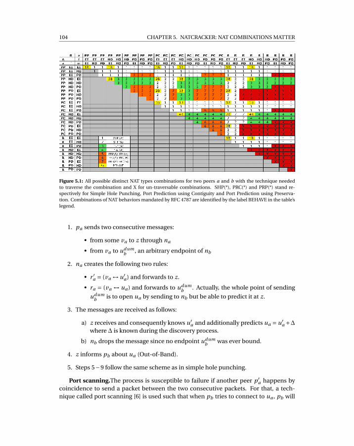
104 CHAPTER 5. NATCRACKER: NAT COMBINATIONS MATTER
Figure 5.1: All possible distinct NAT types combinations for two peers a and b with the technique neededto traverse the combination and X for un-traversable combinations. SHP(*), PRC(*) and PRP(*) stand re-spectively for Simple Hole Punching, Port Prediction using Contiguity and Port Prediction using Preserva-tion. Combinations of NAT behaviors mandated by RFC 4787 are identified by the label BEHAVE in the table’slegend.
1. pa sends two consecutive messages:
• from some va to z through na
• from va to udumb , an arbitrary endpoint of nb
2. na creates the following two rules:
• r ′a = (va ↔ u′
a) and forwards to z.
• ra = (va ↔ ua) and forwards to udumb . Actually, the whole point of sending
udumb is to open ua by sending to nb but be able to predict it at z.
3. The messages are received as follows:
a) z receives and consequently knows u′a and additionally predicts ua = u′
a +∆where ∆ is known during the discovery process.
b) nb drops the message since no endpoint udumb was ever bound.
4. z informs pb about ua (Out-of-Band).
5. Steps 5−9 follow the same scheme as in simple hole punching.
Port scanning.The process is susceptible to failure if another peer p ′a happens by
coincidence to send a packet between the two consecutive packets. For that, a tech-nique called port scanning [6] is used such that when pb tries to connect to ua , pb will
5.7. PREDICTION 105
try ua +∆,ua +2∆,ua +3∆, etc.. until a reply is received. Some gateways might identifythis as a malicious UDP port scan and block it as is the case in some corporate fire-walls. Port scanning might be used only when pb connecting to pa where a(na) = PChas m(nb) < PD , as shown by[6].
5.7.2 Prediction using Preservation (PRP)Another technique is to exploit the port-preservation allocation policy. However, to dothat, we assume that when a peer with port-preservation policy registers at z, the peersupplies a pool of free candidate ports to z. The main point here is to avoid conflicts withports of other peers behind the same NAT. The rendez-vous server z is stateful regardingwhich ports are bound by each NAT and chooses from the pool of the ports supplied bythe peer a port which is not already bound.
1. z chooses some arbitrary port ρ and tells pa (Out-of-Band) to bind ρ
2. pa sends from va where p(va) = ρ to udumb through na .
3. na creates a new rule ra = (va ↔ ua)udumb and forwards to udum
b and since a(pa) =PP, p(ua) = p(va) = ρ.
4. z informs pb about ua (Out-of-Band).
5. Steps 5-9 follow the same scheme as in SHP.
Note that the process is shorter than prediction by contiguity and z chooses the portfor the peer behind NAT instead of the NAT of the peer deciding it and z observing it.However, for the sake of reasoning, the two are equivalent because what matters is whathappens after the opposite peer learns about the punched port irrespective of how theport was predicted.
5.7.3 Prediction-on-a-Single-Side FeasibilityTheorem 5.7.1. Prediction using contiguity or preservation on a single side is feasible forestablishing direct communication between two peers pa and pb respectively behind na
and nb if:
• Condition 1: ∃nx ∈ {na ,nb} s.th. a(nx ) < RD and f (nx ) < PD
• Condition 2: Either m(nx ) < PD or m(nx ) = PD and f (nx′ 6=x ) < PD.
Proof. Similar to theorem 5.6.1, we start with the most restrictive policies and we re-lax until prediction is feasible. The allocation policy of the side to be predicted (na inSection 5.7.2,5.7.1) can not be random, because the whole idea of prediction relies on apredictable allocation policy, thus the needed relaxation is a(na) < RD.
In both prediction techniques, the dummy packet from pa punches a hole by send-ing to pb , in contrast to SHP which punches by sending to z. nevertheless, it is sent to a
106 CHAPTER 5. NATCRACKER: NAT COMBINATIONS MATTER
dummy port of pb . After steps 5, 6:
ra =(
vaf :ua←udum
b←−−−−−−−−→m:va→udum
p
ua
),rb =
(vb
f :ub←ua←−−−−−−→m:vb→ua
ub
)
In step 7: ra
ub 6=udumb6⇐= ←−−−−ub ,ua , we have to relax the filtering at pa to indulge the port
difference from ub , but we tolerate host sensitivity. The needed relaxation is: f (na) < PD
resulting into:
ra =(
vaf :ua←(nb ,∗)←−−−−−−−−→m:va→udum
b
ua
)In step 8: the reasoning about relaxing the mapping on pa or the filtering of pb
is identical to Theorem 5.6.1 except that host-sensitivity is tolerable and thus eitherm(na) < PD or is kept m(na) = PD and in that case, the needed relaxation is f (nb) <PD.
5.7.4 Coverage of PRP & PRCPRP and PRC together cover another 18% of the combinations. That said, we can saythat PRP is as good as SHP in terms of traversal time and success rate (see Section 5.9),which means in addition to the cases where PRP on a single side is used in Figure 5.1,we can also use PRP instead of SHP when the allocation policy is port preservation.
5.8 Interleaved Prediction on Two Sides
. The remaining combinations are these not covered by SHP nor prediction. The finalstretch to go is to do simultaneous prediction on both sides. However, it is a seeminglytricky deadlock situation because every peer needs to know the port that will be openedby the other peer without the other peer sending anything. Which we solve as follows.
Interleaved PRP-PRP. In this case actually double prediction is very simple becausethe rendez-vouz server can pick a port for each side and instruct the involved peers tosimultaneously bind it and start the communication process.
Interleaved PRP-PRC This case is also easily solvable thanks to preservation. Be-cause z can inform the peer with a port contiguity allocation policy about the specificendpoint of the opposite peer. The latter in turn will run a port prediction process usingthe obtained endpoint in the second consecutive message.
Interleaved PRC-PRC This one is the trickiest and it needs a small modification inthe way prediction by contiguity is done. The idea is that the two consecutive packets,the first to z and the second to the opposite peer can not be sent after each other imme-diately. Instead, both peers are commanded by z to send a packet to z itself. From that,z deduces the ports that will be opened on each side in the future and sends to bothpeers informing them about the opposite peer’s predicted endpoint. Both peers in theirturn send a punching packet to each other. The problem with this scheme is that thereis more time between the consecutive packets which makes it more susceptible to thepossibility of another peer behind any of the NATs sending a packet in in between. Like
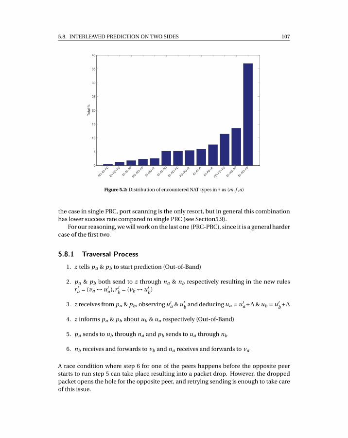
5.8. INTERLEAVED PREDICTION ON TWO SIDES 107
0
5
10
15
20
25
30
35
40
PD EI
PC
EI
HD PC
EI
EI
PP
PD PD PP
EI
HD R
EI
EI
PC
EI
PD PC
PD PD R
EI
EI
R
EI
PD R
PD PD PC
EI
HD PP
EI
PD PP
Tota
l %
Figure 5.2: Distribution of encountered NAT types in τ as (m, f ,a)
the case in single PRC, port scanning is the only resort, but in general this combinationhas lower success rate compared to single PRC (see Section5.9).
For our reasoning, we will work on the last one (PRC-PRC), since it is a general hardercase of the first two.
5.8.1 Traversal Process
1. z tells pa & pb to start prediction (Out-of-Band)
2. pa & pb both send to z through na & nb respectively resulting in the new rulesr ′
a = (va ↔ u′a),r ′
b = (vb ↔ u′b)
3. z receives from pa & pb , observing u′a & u′
b and deducing ua = u′a+∆& ub = u′
b+∆
4. z informs pa & pb about ub & ua respectively (Out-of-Band)
5. pa sends to ub through na and pb sends to ua through nb
6. nb receives and forwards to vb and na receives and forwards to va
A race condition where step 6 for one of the peers happens before the opposite peerstarts to run step 5 can take place resulting into a packet drop. However, the droppedpacket opens the hole for the opposite peer, and retrying sending is enough to take careof this issue.
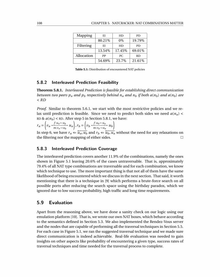
108 CHAPTER 5. NATCRACKER: NAT COMBINATIONS MATTER
Mapping EI HD PD
80.21% 0% 19.79%Filtering EI HD PD
13.54% 17.45% 69.01%Allocation PP PC RD
54.69% 23.7% 21.61%
Table 5.1: Distribution of encountered NAT policies
5.8.2 Interleaved Prediction FeasibilityTheorem 5.8.1. Interleaved Prediction is feasible for establishing direct communicationbetween two peers pa and pb respectively behind na and nb if both a(nb) and a(nb) are< RD
Proof. Similar to theorem 5.6.1, we start with the most restrictive policies and we re-lax until prediction is feasible. Since we need to predict both sides we need a(na) <RD & a(nb) < RD. After step 5 in Section 5.8.1, we have:
ra =(
vaf :ua←ub←−−−−−−→
m:va→ubua
),rb =
(vb
f :ub←ua←−−−−−−→m:vb→ua
ub
)In step 6, we have ra ⇐←−−−−ua ,ub and rb ⇐←−−−−ub ,ua without the need for any relaxations onthe filtering nor the mapping of either sides.
5.8.3 Interleaved Prediction CoverageThe interleaved prediction covers another 11.9% of the combinations, namely the onesshown in Figure 5.1 leaving 20.6% of the cases untraversable. That is, approximately79.4% of all NAT type combinations are traversable and for each combination, we knowwhich technique to use. The more important thing is that not all of them have the samelikelihood of being encountered which we discuss in the next section. That said, it worthmentioning that there is a technique in [9] which performs a brute-force search on allpossible ports after reducing the search space using the birthday paradox, which weignored due to low success probability, high traffic and long time requirements.
5.9 Evaluation
Apart from the reasoning above, we have done a sanity check on our logic using ouremulation platform [10]. That is, we wrote our own NAT boxes, which behave accordingto the semantics defined in Section 5.3. We also implemented the Rendez-Vous serverand the nodes that are capable of performing all the traversal techniques in Section 5.5.For each case in Figure 5.1, we ran the suggested traversal technique and we made suredirect communication is indeed achievable. Real-life evaluation was needed to gaininsights on other aspects like probability of encountering a given type, success rates oftraversal techniques and time needed for the traversal process to complete.
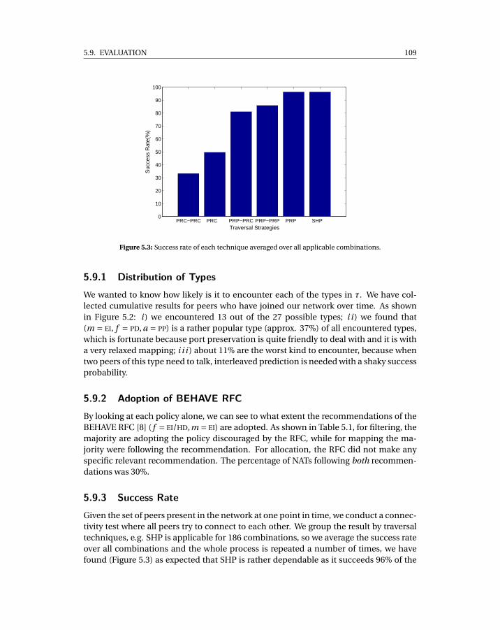
5.9. EVALUATION 109
PRC−PRC PRC PRP−PRC PRP−PRP PRP SHP 0
10
20
30
40
50
60
70
80
90
100
Suc
cess
Rat
e(%
)
Traversal Strategies
Figure 5.3: Success rate of each technique averaged over all applicable combinations.
5.9.1 Distribution of TypesWe wanted to know how likely is it to encounter each of the types in τ. We have col-lected cumulative results for peers who have joined our network over time. As shownin Figure 5.2: i ) we encountered 13 out of the 27 possible types; i i ) we found that(m = EI, f = PD, a = PP) is a rather popular type (approx. 37%) of all encountered types,which is fortunate because port preservation is quite friendly to deal with and it is witha very relaxed mapping; i i i ) about 11% are the worst kind to encounter, because whentwo peers of this type need to talk, interleaved prediction is needed with a shaky successprobability.
5.9.2 Adoption of BEHAVE RFCBy looking at each policy alone, we can see to what extent the recommendations of theBEHAVE RFC [8] ( f = EI/HD,m = EI) are adopted. As shown in Table 5.1, for filtering, themajority are adopting the policy discouraged by the RFC, while for mapping the ma-jority were following the recommendation. For allocation, the RFC did not make anyspecific relevant recommendation. The percentage of NATs following both recommen-dations was 30%.
5.9.3 Success RateGiven the set of peers present in the network at one point in time, we conduct a connec-tivity test where all peers try to connect to each other. We group the result by traversaltechniques, e.g. SHP is applicable for 186 combinations, so we average the success rateover all combinations and the whole process is repeated a number of times, we havefound (Figure 5.3) as expected that SHP is rather dependable as it succeeds 96% of the
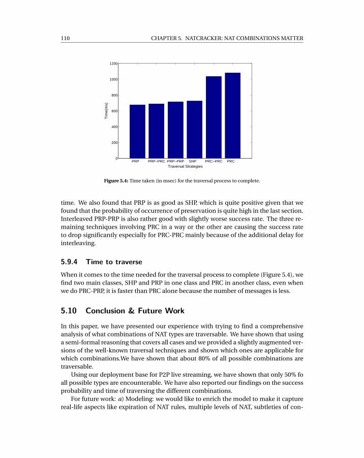
110 CHAPTER 5. NATCRACKER: NAT COMBINATIONS MATTER
PRP PRP−PRC PRP−PRP SHP PRC−PRC PRC 0
200
400
600
800
1000
1200
Tim
e(m
s)
Traversal Strategies
Figure 5.4: Time taken (in msec) for the traversal process to complete.
time. We also found that PRP is as good as SHP, which is quite positive given that wefound that the probability of occurrence of preservation is quite high in the last section.Interleaved PRP-PRP is also rather good with slightly worse success rate. The three re-maining techniques involving PRC in a way or the other are causing the success rateto drop significantly especially for PRC-PRC mainly because of the additional delay forinterleaving.
5.9.4 Time to traverseWhen it comes to the time needed for the traversal process to complete (Figure 5.4), wefind two main classes, SHP and PRP in one class and PRC in another class, even whenwe do PRC-PRP, it is faster than PRC alone because the number of messages is less.
5.10 Conclusion & Future Work
In this paper, we have presented our experience with trying to find a comprehensiveanalysis of what combinations of NAT types are traversable. We have shown that usinga semi-formal reasoning that covers all cases and we provided a slightly augmented ver-sions of the well-known traversal techniques and shown which ones are applicable forwhich combinations.We have shown that about 80% of all possible combinations aretraversable.
Using our deployment base for P2P live streaming, we have shown that only 50% foall possible types are encounterable. We have also reported our findings on the successprobability and time of traversing the different combinations.
For future work: a) Modeling: we would like to enrich the model to make it capturereal-life aspects like expiration of NAT rules, multiple levels of NAT, subtleties of con-
5.11. ACKNOWLEDGMENTS 111
flicts between many peers behind the same NAT, NATs that use different policies in dif-ferent situations, and support for uPnP and TCP; b) Real-life Evaluation: more insightinto the trade-off between success probability and timing, preventing the techniquesas being identified as malicious actions in some corporate firewalls; c) Dissemination:releasing our library and simulator as open-source for third-party improvement andevaluation.
5.11 Acknowledgments
We would like to thank all members of Peerialism’s development team for the help andcollaboration on the implementation of our NAT traversal techniques, in particular Mag-nus Hedbeck for his patience and valuable feedback. The anonymous reviewers of IC-CCN have provided a really inspiring set of comments that helped us to improve thequality of this paper.
5.12 References
[1] Bryan Ford, Pyda Srisuresh, and Dan Kegel. Peer-to-peer communication acrossnetwork address translators. In ATEC ’05: Proceedings of the annual conferenceon USENIX Annual Technical Conference, pages 13–13, Berkeley, CA, USA, 2005.USENIX Association.
[2] P. Srisuresh, B. Ford, and D. Kegel. State of Peer-to-Peer (P2P) Communicationacross Network Address Translators (NATs). RFC 5128 (Informational), March 2008.URL http://www.ietf.org/rfc/rfc5128.txt.
[3] J. Rosenberg, J. Weinberger, C. Huitema, and R. Mahy. STUN - Simple Traversalof User Datagram Protocol (UDP) Through Network Address Translators (NATs).RFC 3489 (Proposed Standard), March 2003. URL http://www.ietf.org/rfc/rfc3489.txt. Obsoleted by RFC 5389.
[4] C. Huitema J. Rosenberg, R. Mahy. Traversal using relays around nat (turn): Relayextensions to session traversal utilities for nat (stun). Internet draft, November2008. URL http://tools.ietf.org/html/draft-ietf-behave-turn-14.
[5] J. Rosenberg. Interactive connectivity establishment (ice): A protocol for networkaddress translator (nat) traversal for offer/answer protocols. Internet draft, Octo-ber 2007. URL http://tools.ietf.org/html/draft-ietf-mmusic-ice-19.
[6] Y. Takeda. Symmetric nat traversal using stun. Internet draft, June 2003. URL http://tools.ietf.org/html/draft-takeda-symmetric-nat-traversal-00.
[7] D. Thaler. Teredo extensions. Internet draft, March 2009. URL http://tools.ietf.org/html/draft-thaler-v6ops-teredo-extensions-03.

112 CHAPTER 5. NATCRACKER: NAT COMBINATIONS MATTER
[8] F. Audet and C. Jennings. Network Address Translation (NAT) Behavioral Require-ments for Unicast UDP. RFC 4787 (Best Current Practice), January 2007. URLhttp://www.ietf.org/rfc/rfc4787.txt.
[9] Andrew Biggadike, Daniel Ferullo, Geoffrey Wilson, and Adrian Perrig. NAT-BLASTER: Establishing TCP connections between hosts behind NATs. In Proceed-ings of ACM SIGCOMM ASIA Workshop, April 2005.
[10] Roberto Roverso, Mohammed Al-Aggan, Amgad Naiem, Andreas Dahlstrom,Sameh El-Ansary, Mohammed El-Beltagy, and Seif Haridi. Myp2pworld: Highly re-producible application-level emulation of p2p systems. In Decentralized Self Man-agement for Grid, P2P, User Communities workshop, SASO 2008, 2008.

CH
AP
TE
R
6DTL: DYNAMIC TRANSPORT LIBRARY FOR
PEER-TO-PEER APPLICATIONS

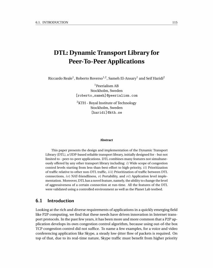
6.1. INTRODUCTION 115
DTL: Dynamic Transport Library forPeer-To-Peer Applications
Riccardo Reale1, Roberto Roverso1,2, Sameh El-Ansary1 and Seif Haridi2
1Peerialism ABStockholm, Sweden
[roberto,sameh]@peerialism.com
2KTH - Royal Institute of TechnologyStockholm, Sweden[haridi]@kth.se
Abstract
This paper presents the design and implementation of the Dynamic TransportLibrary (DTL), a UDP-based reliable transport library, initially designed for - but notlimited to - peer-to-peer applications. DTL combines many features not simultane-ously offered by any other transport library including: i ) Wide scope of congestioncontrol levels starting from less-than-best-effort to high-priority, i i ) Prioritizationof traffic relative to other non-DTL traffic, i i i ) Prioritization of traffic between DTLconnections, i v) NAT-friendliness, v) Portability, and vi ) Application level imple-mentation. Moreover, DTL has a novel feature, namely, the ability to change the levelof aggressiveness of a certain connection at run-time. All the features of the DTLwere validated using a controlled environment as well as the Planet Lab testbed.
6.1 Introduction
Looking at the rich and diverse requirements of applications in a quickly emerging fieldlike P2P computing, we find that these needs have driven innovation in Internet trans-port protocols. In the past few years, it has been more and more common that a P2P ap-plication develops its own congestion control algorithm, because using out-of-the boxTCP congestion control did not suffice. To name a few examples, for a voice and videoconferencing application like Skype, a steady low-jitter flow of packets is required. Ontop of that, due to its real-time nature, Skype traffic must benefit from higher priority
116 CHAPTER 6. DTL: DYNAMIC TRANSPORT LIBRARY FOR PEER-TO-PEER APPLICATIONS
with respect to any other application’s transfer. Thus, Skype developed an application-level proprietary congestion control algorithm [1] known to be very aggressive towardsother applications. On the other end of the spectrum, a content distribution applica-tion like Bittorrent, started initially by using TCP but then switched to LEDBAT, in orderto be polite as much as possible towards other applications, while saturating the linkcapacity. Politeness was critical to eliminate the reputation of Bittorrent as a protocolwhich totally hogs the bandwidth and makes all other applications starve. Between ex-treme politeness and aggressiveness, many other applications can settle for traditionalfair contention over the bandwidth.
The collective state-of-the-art in congestion control algorithms has already addressedmost of the diverse needs of P2P applications. The serious shortcoming is the that thebest known techniques are scattered around in different libraries. This makes it ratherhard for anyone developing a new P2P application to benefit from the progress in thefield. This scattering of ideas in addition to some practical and algorithmic issues thatwe faced while studying other algorithms like LEDBAT, MulTCP and MulTFRC moti-vated our work on the DTL transport library. The idea is to have one single library thatcan practically serve as single one-stop-shop for any P2P application.
The following is a list of the target requirements that we realize in DTL:Priority Levels Supported. The library has to support all levels of traffic prioritizationthat already exist in the congestion control state-of-the-art.Inter-Protocol Prioritization. The library has to give control to the application on howpolite or aggressive it wants to be against other applications.Intra-Protocol Prioritization. The library has to give control to the application onhow polite or aggressive each individual connection is with respect to other connectionwithin the application. A P2P storage application might need, for instance, to have low-priority background transfers for backup purposes and high-priority transfer to fetch afile that has just been shared by another peer.In addition to that, there are some features that have to be there for practical purposes:NAT-Friendliness. The library has to be based on UDP. This makes it easier to circum-vent NAT constraints as UDP NAT traversal procedures are known to be more effectivethan TCP ones [2][3].Application-level implementation. The library has to be implemented in user space,because for all practical purposes, a kernel-level implementation would hinder any suc-cessful wide use. A feature lacking from a rather flexible congestion control library likeMulTCP.Portability. The library shall be available on all platforms, again, that if we want it to bewidely-adopted.Run-Time Dynamic Prioritization. One final feature which we have not previouslyfound in any other library is the ability to not only specify different priorities for dif-ferent connection but to be able to change the priority of a particular connection atrun-time. The need for this feature has arisen, when our team was working on a P2Pvideo streaming application and we needed to tweak the priority of incoming transfersto achieve the necessary playback rate; this by progressively increasing the aggressive-ness towards other traffic in the network. An additional advantage of on-the-fly priority
6.2. RELATED WORK 117
tuning is that it prevents disruptions of existing connections and avoids the need of con-nection re-establishments for transitioning from one priority level to the other or froma congestion control algorithm to the other. In fact, it is known that connection estab-lishments procedures are usually very costly, on the order of several seconds [2], due toexpensive peer-to-peer NAT Traversal and authentication procedures.Finally, the library should support TCP-like reliability and flow control for ease of use.
In this paper, we present how we achieved meeting all aforementioned requirementsin the software we call Dynamic Transport Library or DTL. The paper is organized asfollows: in Section 6.2 we present the state of the art which constitutes the starting pointof our effort. With respect to that, we detail the contribution of our work in Section6.3. In Section 6.4 we explain the design and implementation of the library, while inSection 6.5, we present our library’s evaluation results. We then conclude with somefinal considerations and future work in Section 6.6.
6.2 Related Work
LEDBAT is widely accepted as an effective solution to provide a less-than-best-effortdata transfer service. Initially implemented in the µTorrent BitTorrent client and nowseparately under discussion as an IETF draft [4], LEDBAT is a delay-based congestioncontrol mechanism which aims at saturating the bottleneck link while throttling backtransfers in the presence of flows created by other applications, such as games or VoIPapplications. The yielding procedure is engineered to avoid disruptions to other traf-fic in the network, and it is based on the assumption that growing one-way delays aresymptoms of network congestion. With respect to classical TCP, this allows for earliercongestion detection. LEDBAT was inspired by previous efforts like TCP-Nice [5] andTCP-LP [6] which are based on the same idea.
Our initial goal was to test LEDBAT for background data transfers and later try totweak its parameters to obtain increased aggressiveness and thus higher transfer pri-ority. Although positively impressed by the ability of LEDBAT to minimize the latencyintroduced on the network, we found out that tweaking gain and target delay metricsdoes not lead to a corresponding degree of aggressiveness, as also stated by [7]. As aconsequence, we started to investigate other possible solutions for obtaining tunableaggressiveness transfers. MulTCP [8] provides a mechanism for changing the incrementand decrement parameters of the normal TCP’s AIMD [9] algorithm to emulate the be-havior of a fixed number N of TCP flows in a single transfer. The idea of multiple flowvirtualization is very promising, however the protocol has been experimented only asa kernel module and it is unclear how an application-level implementation would per-form.
MulTFRC [10] extends a previous protocol called TCP Friendly Rate Control (TFRC)[11] to achieve variable transfer aggressiveness. The core idea of TFRC is to achieveTCP-friendliness by explicitly calculating an equation which approximates the steady-state throughput of TCP. MulTFRC modifies the TFRC congestion equation, resultingin a tunable version of the rate control which emulates the behavior of N TFRC flows
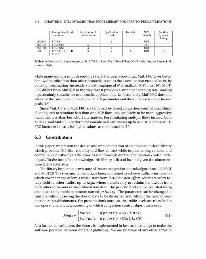
118 CHAPTER 6. DTL: DYNAMIC TRANSPORT LIBRARY FOR PEER-TO-PEER APPLICATIONS
Inter-protocol pri-oritization
Intra-protocolprioritization
Applicationlevel
Portable NAT-friendly
RuntimeDynamic
TuningLEDBAT L-T-B-E X UDPMulTCP L-H, CONT X TCPMulTFRC L-H, CONT X X UDPDTL L-T-B-E & L-H,
CONTX X X UDP X
Table 6.1: Comparison between protocols. L.T.B.E. = Less-Than-Best-Effort, CONT = Continuous Range, L-H.= Low to High
while maintaining a smooth sending rate. It has been shown that MulTFRC gives betterbandwidth utilization than other protocols, such as the Coordination Protocol (CP), bybetter approximating the steady-state throughput of N virtualized TCP flows [10]. MulT-FRC differs from MulTCP in the way that it provides a smoother sending rate, makingit particularly suitable for multimedia applications. Unfortunately, MulTFRC does notallow for the runtime modification of the N parameter and thus, it is not suitable for ourgoals [12].
Since MulTCP and MulTFRC are both packet-based congestion control algorithms,if configured to simulate less than one TCP flow, they are likely to be more aggressivethan other less-than best effort alternatives. For simulating multiple flows instead, bothMulTCP and MulTFRC perform reasonably well with values up to N = 10, but only MulT-FRC increases linearly for higher values, as mentioned in [10].
6.3 Contribution
In this paper, we present the design and implementation of an application-level librarywhich provides TCP-like reliability and flow control while implementing variable andconfigurable on-the-fly traffic prioritization through different congestion control tech-niques. To the best of our knowledge, this library is first of its kind given the aforemen-tioned characteristics.
The library implements two state of the art congestion controls algorithms: LEDBATand MulTCP. The two mechanisms have been combined to achieve traffic prioritizationwhich cover a range of levels which start from less-than-best-effort, where transfers to-tally yield to other traffic, up to high, where transfers try to reclaim bandwidth fromboth other intra- and extra-protocol transfers. The priority level can be adjusted usinga unique configurable parameter named pr i or i t y . The parameter can be changed atruntime without causing the flow of data to be disrupted and without the need of con-nection re-establishments. For presentation’s purpose, the traffic levels are classified intwo operational modes, according to which congestion control algorithm is used:
Mode ={
Pol i te, if pr i or i t y = 0(LEDB AT )
V ar i able, if pr i or i t y > 0(MU LTC P )(6.1)
As a further contribution, the library is implemented in Java as an attempt to make thesoftware portable between different platforms. We are unaware of any other effort to
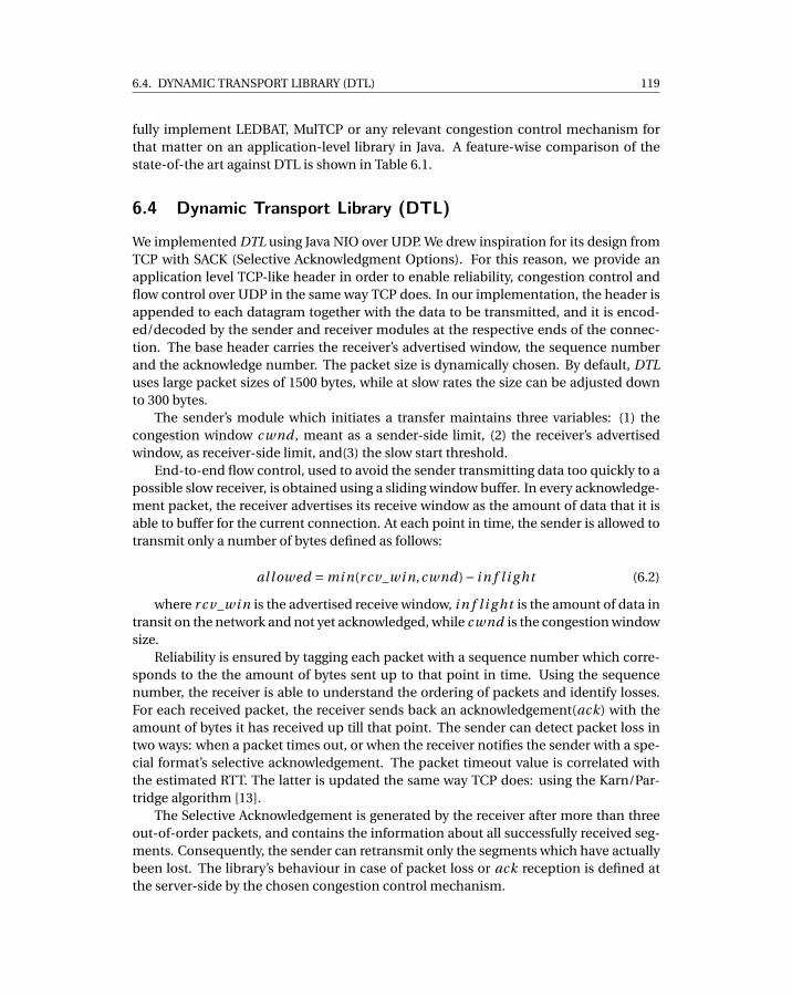
6.4. DYNAMIC TRANSPORT LIBRARY (DTL) 119
fully implement LEDBAT, MulTCP or any relevant congestion control mechanism forthat matter on an application-level library in Java. A feature-wise comparison of thestate-of-the art against DTL is shown in Table 6.1.
6.4 Dynamic Transport Library (DTL)
We implemented DTL using Java NIO over UDP. We drew inspiration for its design fromTCP with SACK (Selective Acknowledgment Options). For this reason, we provide anapplication level TCP-like header in order to enable reliability, congestion control andflow control over UDP in the same way TCP does. In our implementation, the header isappended to each datagram together with the data to be transmitted, and it is encod-ed/decoded by the sender and receiver modules at the respective ends of the connec-tion. The base header carries the receiver’s advertised window, the sequence numberand the acknowledge number. The packet size is dynamically chosen. By default, DTLuses large packet sizes of 1500 bytes, while at slow rates the size can be adjusted downto 300 bytes.
The sender’s module which initiates a transfer maintains three variables: (1) thecongestion window cwnd , meant as a sender-side limit, (2) the receiver’s advertisedwindow, as receiver-side limit, and(3) the slow start threshold.
End-to-end flow control, used to avoid the sender transmitting data too quickly to apossible slow receiver, is obtained using a sliding window buffer. In every acknowledge-ment packet, the receiver advertises its receive window as the amount of data that it isable to buffer for the current connection. At each point in time, the sender is allowed totransmit only a number of bytes defined as follows:
al lowed = mi n(r cv_wi n,cwnd)− i n f l i g ht (6.2)
where r cv_wi n is the advertised receive window, i n f l i g ht is the amount of data intransit on the network and not yet acknowledged, while cwnd is the congestion windowsize.
Reliability is ensured by tagging each packet with a sequence number which corre-sponds to the the amount of bytes sent up to that point in time. Using the sequencenumber, the receiver is able to understand the ordering of packets and identify losses.For each received packet, the receiver sends back an acknowledgement(ack) with theamount of bytes it has received up till that point. The sender can detect packet loss intwo ways: when a packet times out, or when the receiver notifies the sender with a spe-cial format’s selective acknowledgement. The packet timeout value is correlated withthe estimated RTT. The latter is updated the same way TCP does: using the Karn/Par-tridge algorithm [13].
The Selective Acknowledgement is generated by the receiver after more than threeout-of-order packets, and contains the information about all successfully received seg-ments. Consequently, the sender can retransmit only the segments which have actuallybeen lost. The library’s behaviour in case of packet loss or ack reception is defined atthe server-side by the chosen congestion control mechanism.
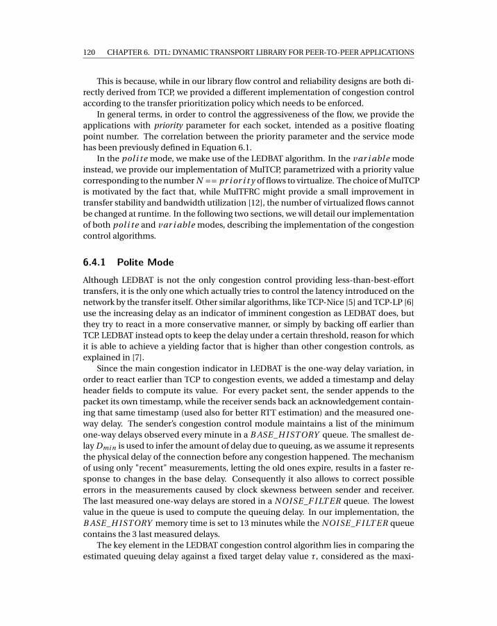
120 CHAPTER 6. DTL: DYNAMIC TRANSPORT LIBRARY FOR PEER-TO-PEER APPLICATIONS
This is because, while in our library flow control and reliability designs are both di-rectly derived from TCP, we provided a different implementation of congestion controlaccording to the transfer prioritization policy which needs to be enforced.
In general terms, in order to control the aggressiveness of the flow, we provide theapplications with priority parameter for each socket, intended as a positive floatingpoint number. The correlation between the priority parameter and the service modehas been previously defined in Equation 6.1.
In the poli te mode, we make use of the LEDBAT algorithm. In the var i abl e modeinstead, we provide our implementation of MulTCP, parametrized with a priority valuecorresponding to the number N == pr i or i t y of flows to virtualize. The choice of MulTCPis motivated by the fact that, while MulTFRC might provide a small improvement intransfer stability and bandwidth utilization [12], the number of virtualized flows cannotbe changed at runtime. In the following two sections, we will detail our implementationof both poli te and var i abl e modes, describing the implementation of the congestioncontrol algorithms.
6.4.1 Polite ModeAlthough LEDBAT is not the only congestion control providing less-than-best-efforttransfers, it is the only one which actually tries to control the latency introduced on thenetwork by the transfer itself. Other similar algorithms, like TCP-Nice [5] and TCP-LP [6]use the increasing delay as an indicator of imminent congestion as LEDBAT does, butthey try to react in a more conservative manner, or simply by backing off earlier thanTCP. LEDBAT instead opts to keep the delay under a certain threshold, reason for whichit is able to achieve a yielding factor that is higher than other congestion controls, asexplained in [7].
Since the main congestion indicator in LEDBAT is the one-way delay variation, inorder to react earlier than TCP to congestion events, we added a timestamp and delayheader fields to compute its value. For every packet sent, the sender appends to thepacket its own timestamp, while the receiver sends back an acknowledgement contain-ing that same timestamp (used also for better RTT estimation) and the measured one-way delay. The sender’s congestion control module maintains a list of the minimumone-way delays observed every minute in a B ASE_H I ST ORY queue. The smallest de-lay Dmi n is used to infer the amount of delay due to queuing, as we assume it representsthe physical delay of the connection before any congestion happened. The mechanismof using only "recent" measurements, letting the old ones expire, results in a faster re-sponse to changes in the base delay. Consequently it also allows to correct possibleerrors in the measurements caused by clock skewness between sender and receiver.The last measured one-way delays are stored in a NOI SE_F I LT ER queue. The lowestvalue in the queue is used to compute the queuing delay. In our implementation, theB ASE_H I ST ORY memory time is set to 13 minutes while the NOI SE_F I LT ER queuecontains the 3 last measured delays.
The key element in the LEDBAT congestion control algorithm lies in comparing theestimated queuing delay against a fixed target delay value τ, considered as the maxi-
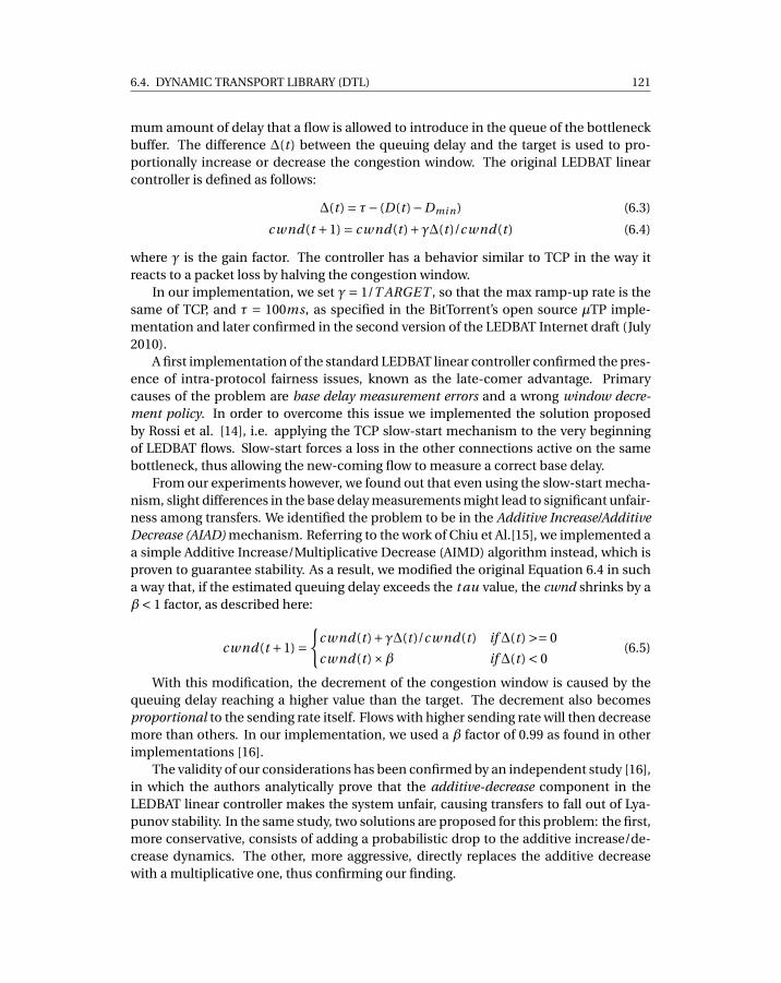
6.4. DYNAMIC TRANSPORT LIBRARY (DTL) 121
mum amount of delay that a flow is allowed to introduce in the queue of the bottleneckbuffer. The difference ∆(t ) between the queuing delay and the target is used to pro-portionally increase or decrease the congestion window. The original LEDBAT linearcontroller is defined as follows:
∆(t ) = τ− (D(t )−Dmi n) (6.3)
cwnd(t +1) = cwnd(t )+γ∆(t )/cwnd(t ) (6.4)
where γ is the gain factor. The controller has a behavior similar to TCP in the way itreacts to a packet loss by halving the congestion window.
In our implementation, we set γ= 1/T ARGET , so that the max ramp-up rate is thesame of TCP, and τ = 100ms, as specified in the BitTorrent’s open source µTP imple-mentation and later confirmed in the second version of the LEDBAT Internet draft (July2010).
A first implementation of the standard LEDBAT linear controller confirmed the pres-ence of intra-protocol fairness issues, known as the late-comer advantage. Primarycauses of the problem are base delay measurement errors and a wrong window decre-ment policy. In order to overcome this issue we implemented the solution proposedby Rossi et al. [14], i.e. applying the TCP slow-start mechanism to the very beginningof LEDBAT flows. Slow-start forces a loss in the other connections active on the samebottleneck, thus allowing the new-coming flow to measure a correct base delay.
From our experiments however, we found out that even using the slow-start mecha-nism, slight differences in the base delay measurements might lead to significant unfair-ness among transfers. We identified the problem to be in the Additive Increase/AdditiveDecrease (AIAD) mechanism. Referring to the work of Chiu et Al.[15], we implemented aa simple Additive Increase/Multiplicative Decrease (AIMD) algorithm instead, which isproven to guarantee stability. As a result, we modified the original Equation 6.4 in sucha way that, if the estimated queuing delay exceeds the t au value, the cwnd shrinks by aβ< 1 factor, as described here:
cwnd(t +1) ={
cwnd(t )+γ∆(t )/cwnd(t ) if ∆(t ) >= 0
cwnd(t )×β if ∆(t ) < 0(6.5)
With this modification, the decrement of the congestion window is caused by thequeuing delay reaching a higher value than the target. The decrement also becomesproportional to the sending rate itself. Flows with higher sending rate will then decreasemore than others. In our implementation, we used a β factor of 0.99 as found in otherimplementations [16].
The validity of our considerations has been confirmed by an independent study [16],in which the authors analytically prove that the additive-decrease component in theLEDBAT linear controller makes the system unfair, causing transfers to fall out of Lya-punov stability. In the same study, two solutions are proposed for this problem: the first,more conservative, consists of adding a probabilistic drop to the additive increase/de-crease dynamics. The other, more aggressive, directly replaces the additive decreasewith a multiplicative one, thus confirming our finding.
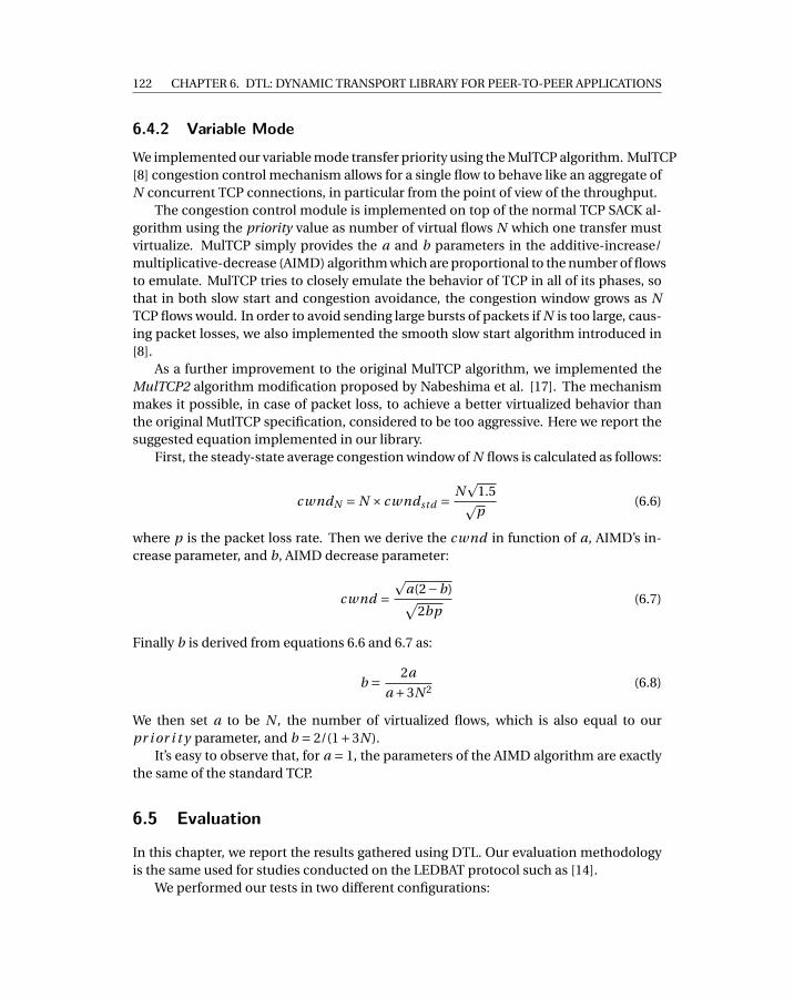
122 CHAPTER 6. DTL: DYNAMIC TRANSPORT LIBRARY FOR PEER-TO-PEER APPLICATIONS
6.4.2 Variable ModeWe implemented our variable mode transfer priority using the MulTCP algorithm. MulTCP[8] congestion control mechanism allows for a single flow to behave like an aggregate ofN concurrent TCP connections, in particular from the point of view of the throughput.
The congestion control module is implemented on top of the normal TCP SACK al-gorithm using the priority value as number of virtual flows N which one transfer mustvirtualize. MulTCP simply provides the a and b parameters in the additive-increase/multiplicative-decrease (AIMD) algorithm which are proportional to the number of flowsto emulate. MulTCP tries to closely emulate the behavior of TCP in all of its phases, sothat in both slow start and congestion avoidance, the congestion window grows as NTCP flows would. In order to avoid sending large bursts of packets if N is too large, caus-ing packet losses, we also implemented the smooth slow start algorithm introduced in[8].
As a further improvement to the original MulTCP algorithm, we implemented theMulTCP2 algorithm modification proposed by Nabeshima et al. [17]. The mechanismmakes it possible, in case of packet loss, to achieve a better virtualized behavior thanthe original MutlTCP specification, considered to be too aggressive. Here we report thesuggested equation implemented in our library.
First, the steady-state average congestion window of N flows is calculated as follows:
cwndN = N × cwndstd = Np
1.5pp
(6.6)
where p is the packet loss rate. Then we derive the cwnd in function of a, AIMD’s in-crease parameter, and b, AIMD decrease parameter:
cwnd =p
a(2−b)√2bp
(6.7)
Finally b is derived from equations 6.6 and 6.7 as:
b = 2a
a +3N 2 (6.8)
We then set a to be N , the number of virtualized flows, which is also equal to ourpr i or i t y parameter, and b = 2/(1+3N ).
It’s easy to observe that, for a = 1, the parameters of the AIMD algorithm are exactlythe same of the standard TCP.
6.5 Evaluation
In this chapter, we report the results gathered using DTL. Our evaluation methodologyis the same used for studies conducted on the LEDBAT protocol such as [14].
We performed our tests in two different configurations:
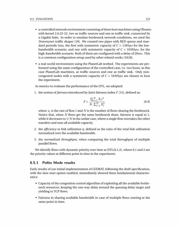
6.5. EVALUATION 123
• a controlled network environment consisting of three host machines using Ubuntuwith kernel 2.6.32-22, two as traffic sources and one as traffic sink, connected bya Gigabit links. In order to emulate bottleneck network conditions, we used theDummynet traffic shaper [18]. We created two pipes with RED queue and stan-dard periodic loss, the first with symmetric capacity of C = 1Mbps for the low-bandwidth scenario, and one with symmetric capacity of C = 10Mbps, for thehigh-bandwidth scenario. Both of them are configured with a delay of 20ms. Thisis a common configuration setup used by other related works [10][8].
• a real-world environment using the PlanetLab testbed. The experiments are per-formed using the same configuration of the controlled case, i.e. two hosts, in thiscase PlanetLab machines, as traffic sources and one as traffic sink. Only non-congested nodes with a symmetric capacity of C = 10Mbps are chosen to hostthe experiment.
As metrics to evaluate the performance of the DTL, we adopted:
1. the notion of fairness introduced by Jain’s fairness index F [15], defined as:
F = (∑N
i=1 Xi )2
N ·∑Ni=1 X 2
i
(6.9)
where xi is the rate of flow i and N is the number of flows sharing the bottleneck.Notice that, when N flows get the same bottleneck share, fairness is equal to 1,while it decreases to 1/N in the unfair case, where a single flow overtakes the othertransfers and uses all available capacity.
2. the efficiency or link utilization η, defined as the ratio of the total link utilizationnormalized over the available bandwidth.
3. the normalized throughput, when comparing the total throughput of multipleparallel flows.
We identify flows with dynamic priority over time as DTL(0,1,2), where 0,1 and 2 arethe priority values at different point in time in the experiment.
6.5.1 Polite Mode resultsEarly results of our initial implementation of LEDBAT, following the draft specification,with the slow start option enabled, immediately showed three fundamental character-istics:
• Capacity of the congestion control algorithm of exploiting all the available bottle-neck resources, keeping the one-way delay around the queuing delay target andyielding to TCP flows.
• Fairness in sharing available bandwidth in case of multiple flows starting at thesame point in time.
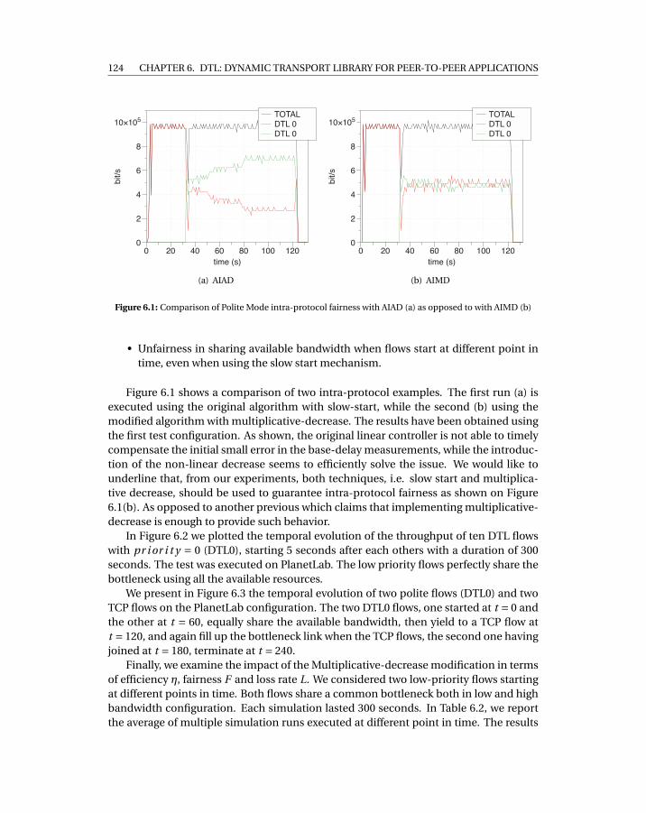
124 CHAPTER 6. DTL: DYNAMIC TRANSPORT LIBRARY FOR PEER-TO-PEER APPLICATIONS
bit/s
0
2
4
6
8
10×105
time (s)
0 20 40 60 80 100 120
TOTAL
DTL 0
DTL 0
(a) AIAD
bit/s
0
2
4
6
8
10×105
time (s)
0 20 40 60 80 100 120
TOTAL
DTL 0
DTL 0
(b) AIMD
Figure 6.1: Comparison of Polite Mode intra-protocol fairness with AIAD (a) as opposed to with AIMD (b)
• Unfairness in sharing available bandwidth when flows start at different point intime, even when using the slow start mechanism.
Figure 6.1 shows a comparison of two intra-protocol examples. The first run (a) isexecuted using the original algorithm with slow-start, while the second (b) using themodified algorithm with multiplicative-decrease. The results have been obtained usingthe first test configuration. As shown, the original linear controller is not able to timelycompensate the initial small error in the base-delay measurements, while the introduc-tion of the non-linear decrease seems to efficiently solve the issue. We would like tounderline that, from our experiments, both techniques, i.e. slow start and multiplica-tive decrease, should be used to guarantee intra-protocol fairness as shown on Figure6.1(b). As opposed to another previous which claims that implementing multiplicative-decrease is enough to provide such behavior.
In Figure 6.2 we plotted the temporal evolution of the throughput of ten DTL flowswith pr i or i t y = 0 (DTL0), starting 5 seconds after each others with a duration of 300seconds. The test was executed on PlanetLab. The low priority flows perfectly share thebottleneck using all the available resources.
We present in Figure 6.3 the temporal evolution of two polite flows (DTL0) and twoTCP flows on the PlanetLab configuration. The two DTL0 flows, one started at t = 0 andthe other at t = 60, equally share the available bandwidth, then yield to a TCP flow att = 120, and again fill up the bottleneck link when the TCP flows, the second one havingjoined at t = 180, terminate at t = 240.
Finally, we examine the impact of the Multiplicative-decrease modification in termsof efficiency η, fairness F and loss rate L. We considered two low-priority flows startingat different points in time. Both flows share a common bottleneck both in low and highbandwidth configuration. Each simulation lasted 300 seconds. In Table 6.2, we reportthe average of multiple simulation runs executed at different point in time. The results
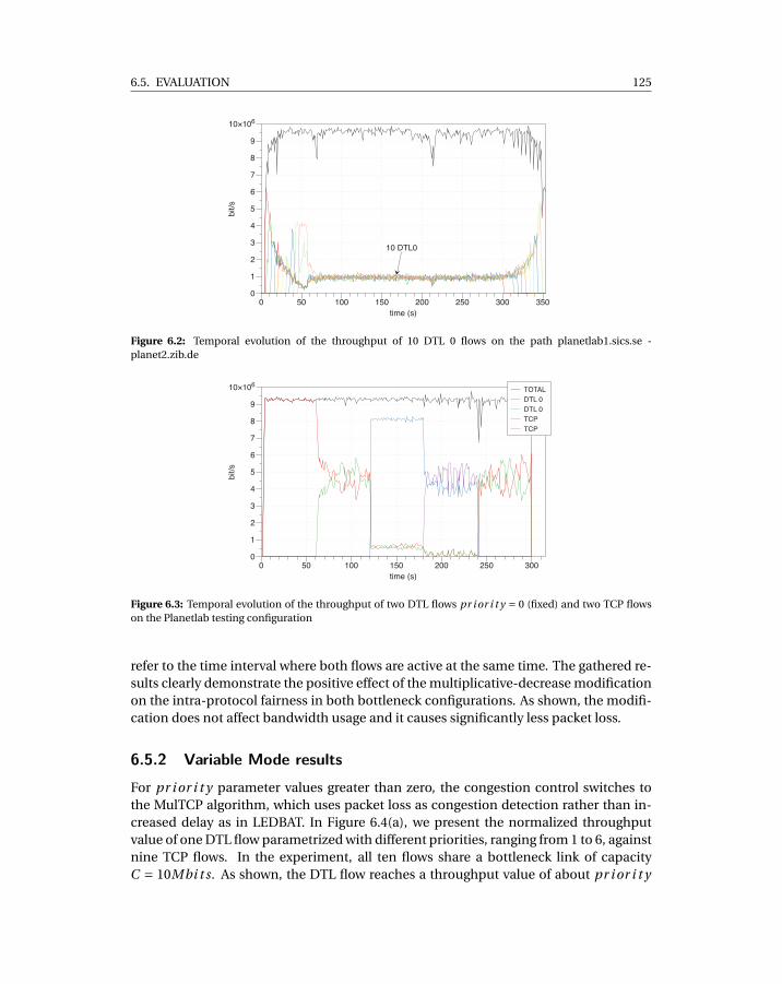
6.5. EVALUATION 125
10 DTL0
bit/s
0
1
2
3
4
5
6
7
8
9
10×106
time (s)
0 50 100 150 200 250 300 350
Figure 6.2: Temporal evolution of the throughput of 10 DTL 0 flows on the path planetlab1.sics.se -planet2.zib.de
bit/s
0
1
2
3
4
5
6
7
8
9
10×106
time (s)
0 50 100 150 200 250 300
TOTAL
DTL 0
DTL 0
TCP
TCP
Figure 6.3: Temporal evolution of the throughput of two DTL flows pr i or i t y = 0 (fixed) and two TCP flowson the Planetlab testing configuration
refer to the time interval where both flows are active at the same time. The gathered re-sults clearly demonstrate the positive effect of the multiplicative-decrease modificationon the intra-protocol fairness in both bottleneck configurations. As shown, the modifi-cation does not affect bandwidth usage and it causes significantly less packet loss.
6.5.2 Variable Mode resultsFor pr i or i t y parameter values greater than zero, the congestion control switches tothe MulTCP algorithm, which uses packet loss as congestion detection rather than in-creased delay as in LEDBAT. In Figure 6.4(a), we present the normalized throughputvalue of one DTL flow parametrized with different priorities, ranging from 1 to 6, againstnine TCP flows. In the experiment, all ten flows share a bottleneck link of capacityC = 10Mbi t s. As shown, the DTL flow reaches a throughput value of about pr i or i t y
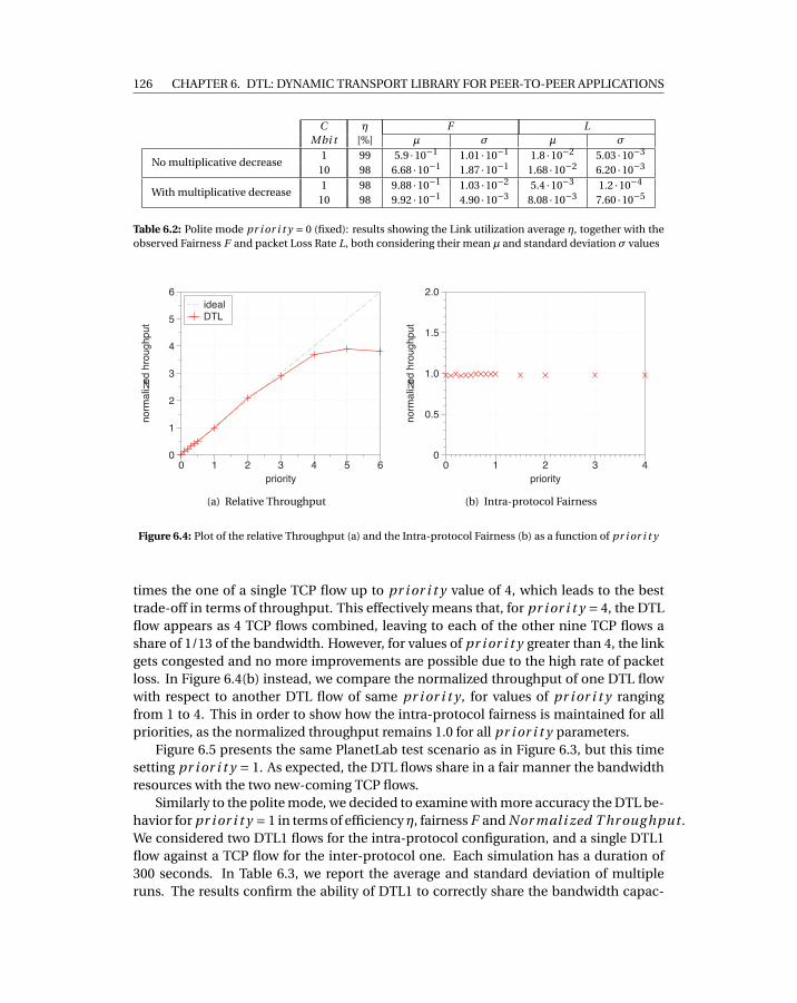
126 CHAPTER 6. DTL: DYNAMIC TRANSPORT LIBRARY FOR PEER-TO-PEER APPLICATIONS
C η F LMbi t [%] µ σ µ σ
No multiplicative decrease1 99 5.9 ·10−1 1.01 ·10−1 1.8 ·10−2 5.03 ·10−3
10 98 6.68 ·10−1 1.87 ·10−1 1.68 ·10−2 6.20 ·10−3
With multiplicative decrease1 98 9.88 ·10−1 1.03 ·10−2 5.4 ·10−3 1.2 ·10−4
10 98 9.92 ·10−1 4.90 ·10−3 8.08 ·10−3 7.60 ·10−5
Table 6.2: Polite mode pr i or i t y = 0 (fixed): results showing the Link utilization average η, together with theobserved Fairness F and packet Loss Rate L, both considering their mean µ and standard deviation σ values
normalized hroughput
0
1
2
3
4
5
6
priority
0 1 2 3 4 5 6
ideal
DTL
(a) Relative Throughput
normalized hroughput
0
0.5
1.0
1.5
2.0
priority
0 1 2 3 4
(b) Intra-protocol Fairness
Figure 6.4: Plot of the relative Throughput (a) and the Intra-protocol Fairness (b) as a function of pr i or i t y
times the one of a single TCP flow up to pr i or i t y value of 4, which leads to the besttrade-off in terms of throughput. This effectively means that, for pr i or i t y = 4, the DTLflow appears as 4 TCP flows combined, leaving to each of the other nine TCP flows ashare of 1/13 of the bandwidth. However, for values of pr i or i t y greater than 4, the linkgets congested and no more improvements are possible due to the high rate of packetloss. In Figure 6.4(b) instead, we compare the normalized throughput of one DTL flowwith respect to another DTL flow of same pr i or i t y , for values of pr i or i t y rangingfrom 1 to 4. This in order to show how the intra-protocol fairness is maintained for allpriorities, as the normalized throughput remains 1.0 for all pr i or i t y parameters.
Figure 6.5 presents the same PlanetLab test scenario as in Figure 6.3, but this timesetting pr i or i t y = 1. As expected, the DTL flows share in a fair manner the bandwidthresources with the two new-coming TCP flows.
Similarly to the polite mode, we decided to examine with more accuracy the DTL be-havior for pr i or i t y = 1 in terms of efficiencyη, fairness F and Nor mal i zed T hr oug hput .We considered two DTL1 flows for the intra-protocol configuration, and a single DTL1flow against a TCP flow for the inter-protocol one. Each simulation has a duration of300 seconds. In Table 6.3, we report the average and standard deviation of multipleruns. The results confirm the ability of DTL1 to correctly share the bandwidth capac-
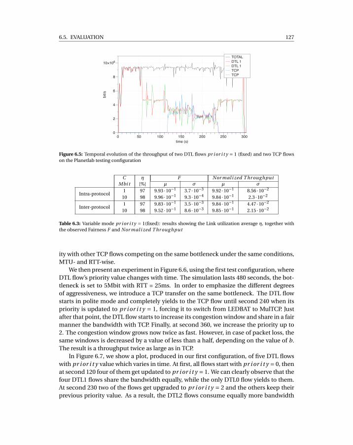
6.5. EVALUATION 127
bit/s
0
2
4
6
8
10×106
time (s)
0 50 100 150 200 250 300
TOTAL
DTL 1
DTL 1
TCP
TCP
Figure 6.5: Temporal evolution of the throughput of two DTL flows pr i or i t y = 1 (fixed) and two TCP flowson the Planetlab testing configuration
C η F Nor mal i zed T hr oug hputMbi t [%] µ σ µ σ
Intra-protocol1 97 9.93 ·10−1 3.7 ·10−3 9.92 ·10−1 8.56 ·10−2
10 98 9.96 ·10−1 9.3 ·10−4 9.84 ·10−1 2.3 ·10−2
Inter-protocol1 97 9.83 ·10−1 3.5 ·10−3 9.84 ·10−1 4.47 ·10−2
10 98 9.52 ·10−1 8.6 ·10−3 9.85 ·10−1 2.15 ·10−2
Table 6.3: Variable mode pr i or i t y = 1(fixed): results showing the Link utilization average η, together withthe observed Fairness F and Nor mal i zed T hr oug hput
ity with other TCP flows competing on the same bottleneck under the same conditions,MTU- and RTT-wise.
We then present an experiment in Figure 6.6, using the first test configuration, whereDTL flow’s priority value changes with time. The simulation lasts 480 seconds, the bot-tleneck is set to 5Mbit with RTT = 25ms. In order to emphasize the different degreesof aggressiveness, we introduce a TCP transfer on the same bottleneck. The DTL flowstarts in polite mode and completely yields to the TCP flow until second 240 when itspriority is updated to pr i or i t y = 1, forcing it to switch from LEDBAT to MulTCP. Justafter that point, the DTL flow starts to increase its congestion window and share in a fairmanner the bandwidth with TCP. Finally, at second 360, we increase the priority up to2. The congestion window grows now twice as fast. However, in case of packet loss, thesame windows is decreased by a value of less than a half, depending on the value of b.The result is a throughput twice as large as in TCP.
In Figure 6.7, we show a plot, produced in our first configuration, of five DTL flowswith pr i or i t y value which varies in time. At first, all flows start with pr i or i t y = 0, thenat second 120 four of them get updated to pr i or i t y = 1. We can clearly observe that thefour DTL1 flows share the bandwidth equally, while the only DTL0 flow yields to them.At second 230 two of the flows get upgraded to pr i or i t y = 2 and the others keep theirprevious priority value. As a result, the DTL2 flows consume equally more bandwidth
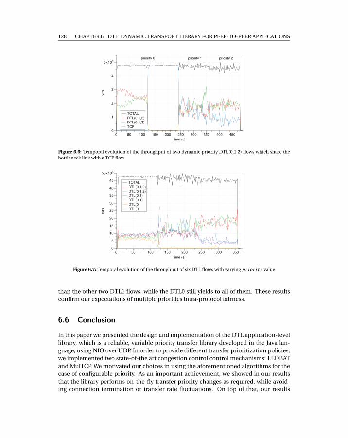
128 CHAPTER 6. DTL: DYNAMIC TRANSPORT LIBRARY FOR PEER-TO-PEER APPLICATIONS
priority 0 priority 1 priority 2
bit/s
0
1
2
3
4
5×10⁶
time (s)
0 50 100 150 200 250 300 350 400 450
TOTAL
DTL(0,1,2)
DTL(0,1,2)
TCP
Figure 6.6: Temporal evolution of the throughput of two dynamic priority DTL(0,1,2) flows which share thebottleneck link with a TCP flow
bit/s
0
5
10
15
20
25
30
35
40
45
50×105
time (s)
0 50 100 150 200 250 300 350
TOTAL
DTL(0,1,2)
DTL(0,1,2)
DTL(0,1)
DTL(0,1)
DTL(0)
DTL(0)
Figure 6.7: Temporal evolution of the throughput of six DTL flows with varying pr i or i t y value
than the other two DTL1 flows, while the DTL0 still yields to all of them. These resultsconfirm our expectations of multiple priorities intra-protocol fairness.
6.6 Conclusion
In this paper we presented the design and implementation of the DTL application-levellibrary, which is a reliable, variable priority transfer library developed in the Java lan-guage, using NIO over UDP. In order to provide different transfer prioritization policies,we implemented two state-of-the art congestion control control mechanisms: LEDBATand MulTCP. We motivated our choices in using the aforementioned algorithms for thecase of configurable priority. As an important achievement, we showed in our resultsthat the library performs on-the-fly transfer priority changes as required, while avoid-ing connection termination or transfer rate fluctuations. On top of that, our results
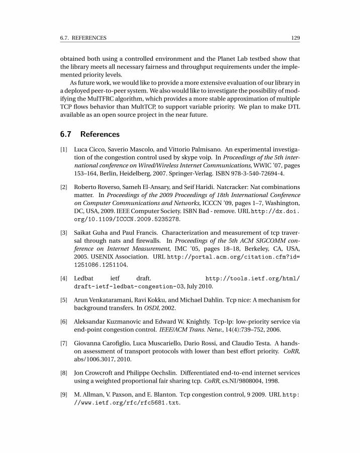
6.7. REFERENCES 129
obtained both using a controlled environment and the Planet Lab testbed show thatthe library meets all necessary fairness and throughput requirements under the imple-mented priority levels.
As future work, we would like to provide a more extensive evaluation of our library ina deployed peer-to-peer system. We also would like to investigate the possibility of mod-ifying the MulTFRC algorithm, which provides a more stable approximation of multipleTCP flows behavior than MultTCP, to support variable priority. We plan to make DTLavailable as an open source project in the near future.
6.7 References
[1] Luca Cicco, Saverio Mascolo, and Vittorio Palmisano. An experimental investiga-tion of the congestion control used by skype voip. In Proceedings of the 5th inter-national conference on Wired/Wireless Internet Communications, WWIC ’07, pages153–164, Berlin, Heidelberg, 2007. Springer-Verlag. ISBN 978-3-540-72694-4.
[2] Roberto Roverso, Sameh El-Ansary, and Seif Haridi. Natcracker: Nat combinationsmatter. In Proceedings of the 2009 Proceedings of 18th International Conferenceon Computer Communications and Networks, ICCCN ’09, pages 1–7, Washington,DC, USA, 2009. IEEE Computer Society. ISBN Bad - remove. URL http://dx.doi.org/10.1109/ICCCN.2009.5235278.
[3] Saikat Guha and Paul Francis. Characterization and measurement of tcp traver-sal through nats and firewalls. In Proceedings of the 5th ACM SIGCOMM con-ference on Internet Measurement, IMC ’05, pages 18–18, Berkeley, CA, USA,2005. USENIX Association. URL http://portal.acm.org/citation.cfm?id=1251086.1251104.
[4] Ledbat ietf draft. http://tools.ietf.org/html/draft-ietf-ledbat-congestion-03, July 2010.
[5] Arun Venkataramani, Ravi Kokku, and Michael Dahlin. Tcp nice: A mechanism forbackground transfers. In OSDI, 2002.
[6] Aleksandar Kuzmanovic and Edward W. Knightly. Tcp-lp: low-priority service viaend-point congestion control. IEEE/ACM Trans. Netw., 14(4):739–752, 2006.
[7] Giovanna Carofiglio, Luca Muscariello, Dario Rossi, and Claudio Testa. A hands-on assessment of transport protocols with lower than best effort priority. CoRR,abs/1006.3017, 2010.
[8] Jon Crowcroft and Philippe Oechslin. Differentiated end-to-end internet servicesusing a weighted proportional fair sharing tcp. CoRR, cs.NI/9808004, 1998.
[9] M. Allman, V. Paxson, and E. Blanton. Tcp congestion control, 9 2009. URL http://www.ietf.org/rfc/rfc5681.txt.
130 CHAPTER 6. DTL: DYNAMIC TRANSPORT LIBRARY FOR PEER-TO-PEER APPLICATIONS
[10] Dragana Damjanovic and Michael Welzl. Multfrc: providing weighted fairness formultimediaapplications (and others too!). Computer Communication Review, 39(3):5–12, 2009.
[11] M. Handley, S. Floyd, J. Padhye, and J. Widmer. Tcp friendly rate control (tfrc):Protocol specification, 2003.
[12] Multfrc ietf draft. http://tools.ietf.org/html/draft-irtf-iccrg-multfrc-01, July 2010.
[13] V. Paxson and M. Allman. Computing tcp’s retransmission timer, 2000.
[14] Dario Rossi, Claudio Testa, Silvio Valenti, Paolo Veglia, and Luca Muscariello. Newsfrom the internet congestion control world. CoRR, abs/0908.0812, 2009.
[15] Dah-Ming Chiu and Raj Jain. Analysis of the increase and decrease algorithms forcongestion avoidance in computer networks. Computer Networks, 17:1–14, 1989.
[16] Giovanna Carofiglio, Luca Muscariello, Dario Rossi, and Silvio Valenti. The questfor ledbat fairness. CoRR, abs/1006.3018, 2010.
[17] Masayoshi Nabeshima. Performance evaluation of multcp in high-speed wide areanetworks. IEICE Transactions, 88-B(1):392–396, 2005.
[18] Marta Carbone and Luigi Rizzo. Dummynet revisited. Computer CommunicationReview, 40(2):12–20, 2010.

PART IV
Peer Sampling
131


CH
AP
TE
R
7THROUGH THE WORMHOLE: LOW COST,FRESH PEER SAMPLING FOR THE
INTERNET

135
Through the Wormhole: Low Cost, Fresh PeerSampling for the Internet
Roberto Roverso1,2, Jim Dowling2 and Mark Jelacity3
1Peerialism ABStockholm, Sweden
[roberto,sameh]@peerialism.com
2KTH - Royal Institute of TechnologyStockholm, Sweden
[email protected] 3University of Szeged, and
Hungarian Academy of [email protected]
Abstract
State of the art gossip protocols for the Internet are based on the assumptionthat connection establishment between peers comes at negligible cost. Our expe-rience with commercially deployed P2P systems has shown that this cost is muchhigher than generally assumed. As such, peer sampling services often cannot pro-vide fresh samples because the service would require too high a connection estab-lishment rate. In this paper, we present the wormhole-based peer sampling service(WPSS). WPSS overcomes the limitations of existing protocols by executing shortrandom walks over a stable topology and by using shortcuts (wormholes), thus lim-iting the rate of connection establishments and guaranteeing freshness of samples,respectively. We show that our approach can decrease the connection establishmentrate by one order of magnitude compared to the state of the art while providing thesame levels of freshness of samples. This, without sacrificing the desirable proper-ties of a PSS for the Internet, such as robustness to churn and NAT-friendliness. Wesupport our claims with a thorough measurement study in our deployed commer-cial system as well as in simulation.
136
CHAPTER 7. THROUGH THE WORMHOLE: LOW COST, FRESH PEER SAMPLING FOR THE
INTERNET
7.1 Introduction
A peer sampling service (PSS) provides nodes in a distributed system with a uniformrandom sample of live nodes from all nodes in the system, where the sample size istypically much smaller than the system size. PSSes are widely used by peer-to-peer(P2P) applications to periodically discover new peers in a system and to calculate sys-tem statistics. A PSS can be implemented as a centralized service [1], using gossip pro-tocols [2] or random walks [3]. Gossip-based PSSes have been the most widely adoptedsolution, as centralized PSSes are expensive to run reliably, and random walks are onlysuitable for stable networks, i.e. with very low levels of churn [3].
Classical gossip-based PSSes [2] assume that all nodes can communicate directlywith one another, but these protocols break down on the open Internet [4], where alarge majority of nodes do not support direct connectivity as they reside behind Net-work Address Translation Gateways (NATs) and firewalls. To overcome this problem, anew class of NAT-aware gossip-based PSSes have appeared that are able to generate uni-formly random node samples even for systems with a high percentage of private nodes,that is, nodes that reside behind a NAT and/or firewall [4, 5, 6].
State of the art NAT-aware gossip protocols, such as Gozar [4] and Croupier [5], re-quire peers to frequently establish network connections and exchange messages withpublic nodes, nodes that support direct connectivity, in order to build a view of the over-lay network. These designs are based on two assumptions: i) connection establishmentfrom a private to a public peer comes at negligible cost, and ii) the connection setuptime is short and predictable. However, these assumptions do not hold for many classesof P2P applications. In particular, in commercial P2P applications such as Spotify [1],P2P-Skype [7], and Google’s WebRTC [8] establishing a connection is a relatively com-plex and costly procedure. This is primarily because security is a concern. All new con-nections require peers to authenticate the other party with a trusted source, typically asecure server, and to setup an encrypted channel. Another reason is that establishinga new connection may involve coordination by a helper service, for instance, to workaround connectivity limitations that are not captured by NAT detection algorithms orthat are caused by faulty network configurations. To put this in the perspective of ourP2P live streaming system [9], which we believe is representative of many commercialP2P systems, all these factors combined produce connection setup times which canrange from few tenths of a second up to a few seconds, depending on network latencies,congestion, and the complexity of the connection establishment procedure. In addi-tion to these factors, public nodes are vulnerable to denial-of-service attacks, as thereexists an upper bound on the rate of new connections that peers are able to establish ina certain period of time.
It is, therefore, preferable in our application to build a PSS over a more stable topol-ogy than the constantly changing topologies built by continuous gossiping exchanges.An instance of such a stable topology might be an overlay network where connectionsbetween peers are maintained over time and node degree is kept constant by replacingfailed connections. Random walks (RWs) over such a stable overlay are potentially analternative to NAT-resilient gossip protocols. However, we are not aware of any work
7.2. SYSTEM MODEL 137
which addresses the problem of random walks over the Internet in presence of NATs.That said, RW methods over other stable networks that are not the Internet[10] are notpractical in our case because of the high level of churn experienced in P2P systems,which causes the PSS’ quality of service to degrade by interrupting or delaying the RWs.Furthermore, RWs are not able to provide fresh-enough samples because a random walkhas to complete a large number of hops (depending on the topology of the network) tocollect or deposit a sample.
In this paper, we present an alternative approach where the PSS creates enough newconnections to ensure the PSS’ quality of service in the face of peer churn, but not toomany as to exceed peers’ upper bounds on connection establishment rate. We call oursystem a wormhole-based PSS (WPSS). WPSS can tune the number of new stable net-work connections established per sample to match application-level requirements andconstraints. We show that our system can provide the same level of freshness of sam-ples as the state of the art in NAT-aware PSSes [5] but with a connection establishmentrate that is one order of magnitude lower. This, without sacrificing the desirable prop-erties of a PSS for the Internet, such as robustness to churn, NAT-friendliness and localrandomness of samples.
The main idea behind WPSS is that we separate the service into two layers. The bot-tom layer consists of a stable base overlay network that should be NAT-friendly, withprivate nodes connecting to public nodes, while public nodes connect to one another.On top of this overlay, every node periodically connects to a random public node se-lected from the base overlay (not necessarily a neighbor in the base overlay). Using therandom public node, each node systematically places samples of itself on nodes in theneighborhood of this random public node. We call these links to random public nodeswormholes. That is, a wormhole is a link to a public node that is selected uniformly andindependently at random. We do not require hole-punching or relaying to private nodesin this paper, although those techniques can be used as well if there are not enough pub-lic nodes.
In addition to explaining the WPSS algorithm (Section 7.4), our contributions alsoinclude a analytical comparison between WPSS and related work (Section 7.5), and athorough evaluation of the protocol in both simulation and our deployed system (Sec-tion 7.6). The latter experiments include a comparison with the state of the art NAT-resilient PSS, Croupier.
7.2 System Model
We model a distributed system as a network of autonomous nodes that exchange mes-sages and execute the same protocol. Nodes join and leave the system continuously. Weconsider large-scale networked systems with limited connectivity, for example, where alarge majority of nodes reside behind NAT devices or firewalls. A public node has a glob-ally reachable IP address; this includes nodes that use IP addresses allocated by UPnPInternet Gateway Devices. A private node does not support direct connectivity, typically,because it is behind a firewall or a NAT.
138
CHAPTER 7. THROUGH THE WORMHOLE: LOW COST, FRESH PEER SAMPLING FOR THE
INTERNET
Each node discovers its NAT type (public or private) at bootstrap-time and also whenits IP address changes using a NAT-type identification protocol. We also assume that abootstrap service provides newly joined nodes with a small number of node descriptorsfor live nodes in the system. Each node separately maintains open network connectionsto a small, bounded number of randomly selected public nodes in a stable base overlay.The node degree on the base overlay is kept constant over time by replacing connectionsto failed nodes with new ones.
7.3 Background and Related Work
The first generation of peer sampling services were not designed to account for NATs [2,11, 12]. In recent years, researchers have worked on NAT-aware gossip protocols [13],and the first NAT-aware PSSes were Nylon [6] and Gozar [4]. They enabled gossipingwith a private node by relaying a message via an existing node in the system that had al-ready successfully communicated with the private node. Nylon routes packets to a pri-vate node using routing tables maintained at all nodes in the system. In contrast, Gozarroutes packets to a private node using an existing public node in the system. Gozar doesnot require routing tables as the address of a private node includes the addresses of jpublic nodes that can act as relays to it. To improve Gozar’s reliability, gossip messagescan be sent to a private node in parallel via its j relays, where j is a system parameter.Parallelizing relay messages also reduces the latency of gossip messages, but at the costof an increase in protocol overhead. Both Nylon and Gozar require that private nodesrefresh their NAT bindings by periodically pinging their neighbors.
Croupier [5] provided an alternative NAT-aware PSS that removed the need for re-laying gossip messages to private nodes. Instead of routing gossip messages to privatenodes, gossip requests are only sent to public nodes that act as croupiers, shuffling nodedescriptors on behalf of both public and private nodes. Public nodes are able to sendresponse messages through a private node’s NAT, as the shuffle request from the privatenode created a NAT binding rule that is subsequently used to forward the response tothe private node. Two similarities between Croupier and WPSS are that nodes need toknow whether they are public or private, and that the stable topology created by WPSS issimilar to the dynamic topology maintained by Croupier, where both private and publicnodes only connect to public nodes. In contrast to WPSS, Croupier provides a decentral-ized NAT-type identification protocol to discover a node’s NAT type (public or private),while our system provides an infrastructure-supported service based on [14].
One general difference between gossip-based approaches and WPSS is that a gossipmessage combines both the advertisement of the source node’s descriptor as well asa set of other node descriptors for dissemination [2][11], while WPSS messages onlycontain an advertisement of the initiating node’s descriptor, making the message sizesomewhat smaller.
PSSes have also been implemented using independent RWs on stable, and even veryslowly changing, dynamic graphs [3]. Intuitively, RWs work by repeatedly injecting ran-domness at each step until the initiator node is forgotten. RW sampling can be classified
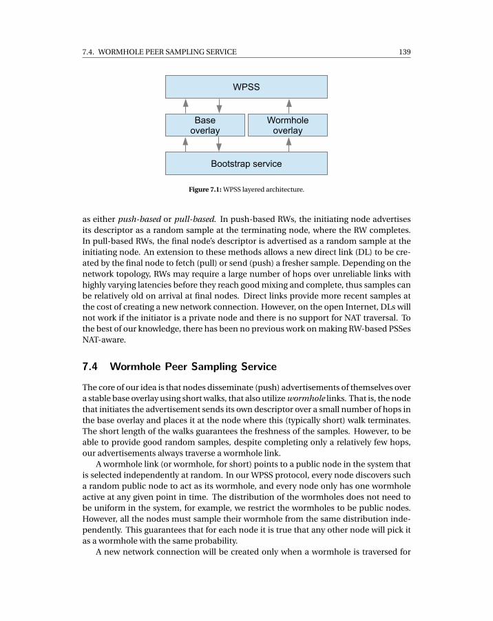
7.4. WORMHOLE PEER SAMPLING SERVICE 139
WPSS
Wormholeoverlay
Baseoverlay
Bootstrap service
Figure 7.1: WPSS layered architecture.
as either push-based or pull-based. In push-based RWs, the initiating node advertisesits descriptor as a random sample at the terminating node, where the RW completes.In pull-based RWs, the final node’s descriptor is advertised as a random sample at theinitiating node. An extension to these methods allows a new direct link (DL) to be cre-ated by the final node to fetch (pull) or send (push) a fresher sample. Depending on thenetwork topology, RWs may require a large number of hops over unreliable links withhighly varying latencies before they reach good mixing and complete, thus samples canbe relatively old on arrival at final nodes. Direct links provide more recent samples atthe cost of creating a new network connection. However, on the open Internet, DLs willnot work if the initiator is a private node and there is no support for NAT traversal. Tothe best of our knowledge, there has been no previous work on making RW-based PSSesNAT-aware.
7.4 Wormhole Peer Sampling Service
The core of our idea is that nodes disseminate (push) advertisements of themselves overa stable base overlay using short walks, that also utilize wormhole links. That is, the nodethat initiates the advertisement sends its own descriptor over a small number of hops inthe base overlay and places it at the node where this (typically short) walk terminates.The short length of the walks guarantees the freshness of the samples. However, to beable to provide good random samples, despite completing only a relatively few hops,our advertisements always traverse a wormhole link.
A wormhole link (or wormhole, for short) points to a public node in the system thatis selected independently at random. In our WPSS protocol, every node discovers sucha random public node to act as its wormhole, and every node only has one wormholeactive at any given point in time. The distribution of the wormholes does not need tobe uniform in the system, for example, we restrict the wormholes to be public nodes.However, all the nodes must sample their wormhole from the same distribution inde-pendently. This guarantees that for each node it is true that any other node will pick itas a wormhole with the same probability.
A new network connection will be created only when a wormhole is traversed for
140
CHAPTER 7. THROUGH THE WORMHOLE: LOW COST, FRESH PEER SAMPLING FOR THE
INTERNET
the first time by an advertisement. The wormhole is then reused for a few subsequentadvertisements from the same initiator node, in which case no new network connectionneeds to be established. This makes it possible to decrease the number of new links weestablish.
The very first time an advertisement traverses the wormhole, it can be consideredto have reached a random public node. Thus, the advertisement can now be placed atthe public node as a new sample. However, if the wormhole has already been used, orthe public node already has a sample from the initiator node, then the advertisementwill start a random walk over the base overlay until it either (1) reaches a node thatdoes not already have a sample from the initiator node or (2) it reaches a given time-to-live (TTL) that guarantees good quality sampling. Clearly, as a wormhole creates alink to a public node, advertisements through it will place a sample first at that publicnode unless it already has an advertisement from the initiator. However, the reuse ofthe wormhole causes advertisements to continue, allowing them to also finish at privatenodes, as private nodes are connected to public nodes over the base overlay.
When a wormhole is reused by a advertisement, the expected number of hops theadvertisement will have to take increases, as it needs to reach a node that does not al-ready have a sample from the initiator node. To counteract this, new wormholes are cre-ated. WPSS defines a wormhole renewal period as a parameter for creating new worm-holes enabling users to control how frequently new network connections will be cre-ated. If a new wormhole is created for each advertisement, then we get a protocol verysimilar to RW-push-DL (see Section 7.5). If wormholes are never updated, the behav-ior converges to that of RW-push, eventually. In between, there is a range of interestingprotocols some of which—as we will argue—achieve the goals we set.
We illustrate the interaction between the wormholes and the base overlay in Fig-ure 7.2. In the figure, the bottom layer is the base overlay, while the upper layer showsthe wormhole overlay, containing a single wormhole. The upper layer also shows twoadvertisements over the wormhole that follow links in the base overlay to place samplesin the vicinity of the wormhole.
7.4.1 WPSS ArchitectureWe implemented WPSS in a modular, layered architecture, illustrated in Figure 7.1. WPSSrequires a stable base overlay and a set of wormhole links. It is very important that thewormhole links are drawn independently from an identical (but not necessarily uni-form) distribution. Since the random samples generated using wormholes do not guar-antee inter-node independence, these samples cannot be used to generate new worm-hole links. So, another PSS is required that provides independent samples of publicnodes. We call this the bootstrap PSS. The bootstrap PSS will have relatively low load,since wormholes are refreshed rarely, given that WPSS is designed to reduce the numberof new network connections created. For this reason, the bootstrap PSS can be imple-mented even as a central server. Alternatively, public nodes can generate independentsamples by periodically starting random walks that continue until they reach their TTL.
In our architecture, the base overlay can be any connected overlay, as long as the
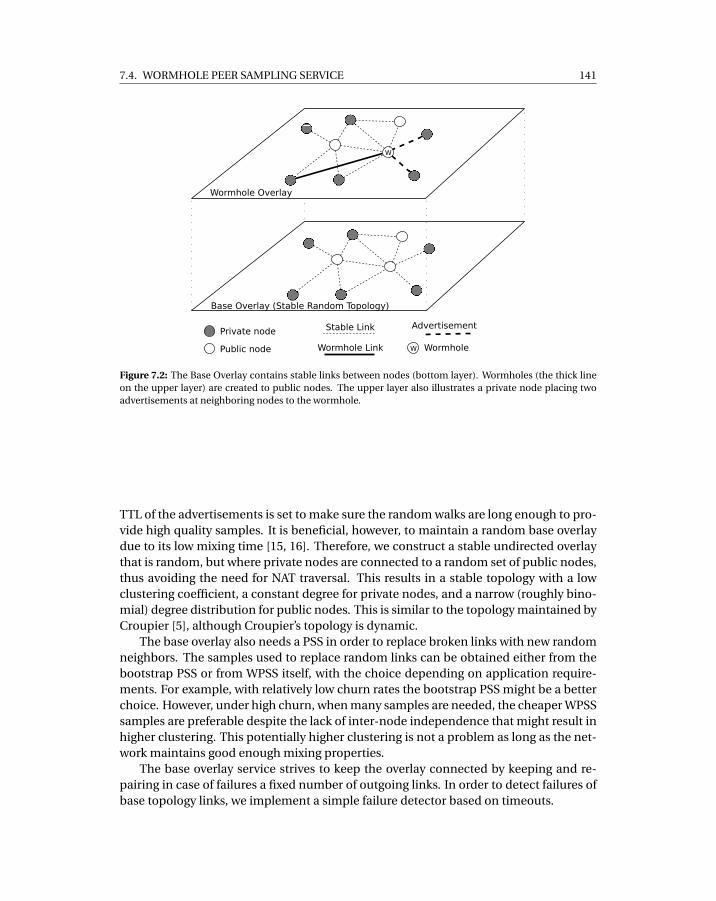
7.4. WORMHOLE PEER SAMPLING SERVICE 141
Base Overlay (Stable Random Topology)
Wormhole Overlay
W
Private node
Public node
Stable Link
Wormhole Link
Advertisement
W Wormhole
Figure 7.2: The Base Overlay contains stable links between nodes (bottom layer). Wormholes (the thick lineon the upper layer) are created to public nodes. The upper layer also illustrates a private node placing twoadvertisements at neighboring nodes to the wormhole.
TTL of the advertisements is set to make sure the random walks are long enough to pro-vide high quality samples. It is beneficial, however, to maintain a random base overlaydue to its low mixing time [15, 16]. Therefore, we construct a stable undirected overlaythat is random, but where private nodes are connected to a random set of public nodes,thus avoiding the need for NAT traversal. This results in a stable topology with a lowclustering coefficient, a constant degree for private nodes, and a narrow (roughly bino-mial) degree distribution for public nodes. This is similar to the topology maintained byCroupier [5], although Croupier’s topology is dynamic.
The base overlay also needs a PSS in order to replace broken links with new randomneighbors. The samples used to replace random links can be obtained either from thebootstrap PSS or from WPSS itself, with the choice depending on application require-ments. For example, with relatively low churn rates the bootstrap PSS might be a betterchoice. However, under high churn, when many samples are needed, the cheaper WPSSsamples are preferable despite the lack of inter-node independence that might result inhigher clustering. This potentially higher clustering is not a problem as long as the net-work maintains good enough mixing properties.
The base overlay service strives to keep the overlay connected by keeping and re-pairing in case of failures a fixed number of outgoing links. In order to detect failures ofbase topology links, we implement a simple failure detector based on timeouts.
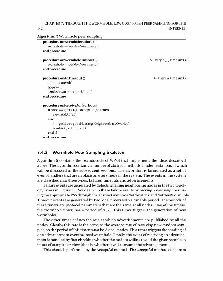
142
CHAPTER 7. THROUGH THE WORMHOLE: LOW COST, FRESH PEER SAMPLING FOR THE
INTERNET
Algorithm 5 Wormhole peer samplingprocedure onWormholeFailure ⟨⟩
wormhole ← getNewWormhole()end procedure
procedure onWormholeTimeout ⟨⟩ . Every ∆wh time unitswormhole ← getNewWormhole()
end procedure
procedure onAdTimeout ⟨⟩ . Every ∆ time unitsad ← createAd()hops ← 1sendAd(wormhole, ad, hops)
end procedure
procedure onReceiveAd ⟨ad, hops⟩if hops == getTTL() || acceptAd(ad) then
view.addAd(ad)else
j ← getMetropolisHastingsNeighbor(baseOverlay)sendAd(j, ad, hops+1)
end ifend procedure
7.4.2 Wormhole Peer Sampling Skeleton
Algorithm 5 contains the pseudocode of WPSS that implements the ideas describedabove. The algorithm contains a number of abstract methods, implementations of whichwill be discussed in the subsequent sections. The algorithm is formulated as a set ofevent-handlers that are in place on every node in the system. The events in the systemare classified into three types: failures, timeouts and advertisements.
Failure events are generated by detecting failing neighboring nodes in the two topol-ogy layers in Figure 7.1. We deal with these failure events by picking a new neighbor us-ing the appropriate PSS through the abstract methods GetNewLink and GetNewWormhole.Timeout events are generated by two local timers with a tunable period. The periods ofthese timers are protocol parameters that are the same at all nodes. One of the timers,the wormhole timer, has a period of ∆wh . This timer triggers the generation of newwormholes.
The other timer defines the rate at which advertisements are published by all thenodes. Clearly, this rate is the same as the average rate of receiving new random sam-ples, so the period of this timer must be∆ at all nodes. This timer triggers the sending ofone advertisement over the local wormhole. Finally, the event of receiving an advertise-ment is handled by first checking whether the node is willing to add the given sample toits set of samples or View (that is, whether it will consume the advertisement).
This check is performed by the AcceptAd method. The AcceptAd method consumes
7.5. ANALYTICAL COMPARISON 143
an advertisement only if its sample is not already contained in the node’s view, thuspromoting diversity of samples. On top of that, AcceptAd makes sure that every nodeconsumes advertisements at the same rate, namely one advertisement in each ∆ timeperiod. We implement this rate control mechanism only at the public nodes; if the ac-ceptance rate on the public nodes is 1/∆, then private nodes are guaranteed to observethe same rate on average due to the advertisement generation rate being 1/∆ at all thenodes. To control the rate, we need to approximate the period of receiving advertise-ments. To do this, we calculate the running average and the average deviation of thedelays between consecutive acceptance events. If the approximated period, increasedby mean deviation, is higher than∆ then the advertisement is accepted and the approx-imation of the period is updated. We show later in Section 7.6 that the AcceptAd methodsuccessfully balances advertisements over public and private nodes.
If the node does not consume the advertisement, it sends it on to another node usingthe Metropolis-Hastings transition probabilities over the (random, stable) base networkwhich results in a uniform stationary distribution [17]. Let di denote the degree of nodei , that is, the number of neighbors of node i . Note that the graph is undirected. Theimplementation of GetMetropolisHastingsNeighbor works as follows. First, we select aneighbor j with uniform probability, that is, with probability 1/di . Then, we return jwith probability min(di /d j ,1), otherwise we return node i itself, that is, the advertise-ment will visit i again.
Note that the node will consume the advertisement also if the TTL of the advertise-ment is reached, since at that point it can be considered a uniform random sample. TheTTL is returned by GetTTL, that can be implemented in many different ways dependingon the system properties. We simply set a constant TTL in our experiments.
7.5 Analytical comparison
Here, we provide an analytical comparison between related work and WPSS. In orderto do that, we develop a number of metrics and criteria. As a general assumption, weassume that the considered PSSes provide a continuous stream of random node de-scriptors at every node in the network. To be more precise, we require each node toreceive one sample every ∆ time units on average, where ∆ is the sampling period.
7.5.1 Metrics of Quality of Service and CostThe minimum that we assume about any PSS is that the stream of samples at a givenfixed node is unbiased (that is, the samples received by a node are independent of thenode) and that samples are uniform (that is, any fixed individual sample has a uniformdistribution). These properties hold for WPSS. This is almost trivial and can be formallyproven using the facts that WPSS is blind to the content of node descriptors and worm-holes are random. The technical proof is omitted due to lack of space.
Apart from this, we characterize the quality of service using the properties of fresh-ness and independence. Freshness is the age of the sample, that is, the delay betweenthe recording of the sample at the source node and its delivery at the terminating node.
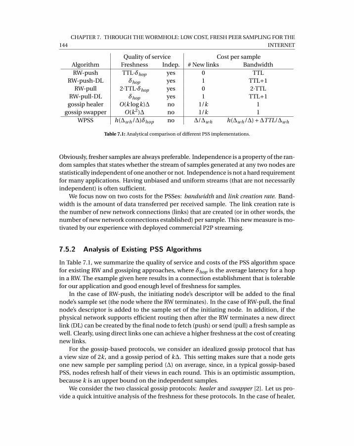
144
CHAPTER 7. THROUGH THE WORMHOLE: LOW COST, FRESH PEER SAMPLING FOR THE
INTERNET
Quality of service Cost per sampleAlgorithm Freshness Indep. # New links BandwidthRW-push TTL·δhop yes 0 TTL
RW-push-DL δhop yes 1 TTL+1RW-pull 2·TTL·δhop yes 0 2·TTL
RW-pull-DL δhop yes 1 TTL+1gossip healer O(k logk)∆ no 1/k 1
gossip swapper O(k2)∆ no 1/k 1WPSS h(∆wh/∆)δhop no ∆/∆wh h(∆wh/∆)+∆TTL/∆wh
Table 7.1: Analytical comparison of different PSS implementations.
Obviously, fresher samples are always preferable. Independence is a property of the ran-dom samples that states whether the stream of samples generated at any two nodes arestatistically independent of one another or not. Independence is not a hard requirementfor many applications. Having unbiased and uniform streams (that are not necessarilyindependent) is often sufficient.
We focus now on two costs for the PSSes: bandwidth and link creation rate. Band-width is the amount of data transferred per received sample. The link creation rate isthe number of new network connections (links) that are created (or in other words, thenumber of new network connections established) per sample. This new measure is mo-tivated by our experience with deployed commercial P2P streaming.
7.5.2 Analysis of Existing PSS Algorithms
In Table 7.1, we summarize the quality of service and costs of the PSS algorithm spacefor existing RW and gossiping approaches, where δhop is the average latency for a hopin a RW. The example given here results in a connection establishment that is tolerablefor our application and good enough level of freshness for samples.
In the case of RW-push, the initiating node’s descriptor will be added to the finalnode’s sample set (the node where the RW terminates). In the case of RW-pull, the finalnode’s descriptor is added to the sample set of the initiating node. In addition, if thephysical network supports efficient routing then after the RW terminates a new directlink (DL) can be created by the final node to fetch (push) or send (pull) a fresh sample aswell. Clearly, using direct links one can achieve a higher freshness at the cost of creatingnew links.
For the gossip-based protocols, we consider an idealized gossip protocol that hasa view size of 2k, and a gossip period of k∆. This setting makes sure that a node getsone new sample per sampling period (∆) on average, since, in a typical gossip-basedPSS, nodes refresh half of their views in each round. This is an optimistic assumption,because k is an upper bound on the independent samples.
We consider the two classical gossip protocols: healer and swapper [2]. Let us pro-vide a quick intuitive analysis of the freshness for these protocols. In the case of healer,
7.5. ANALYTICAL COMPARISON 145
fresher descriptors always have preference when spreading. This results in an expo-nential initial spreading of newly inserted descriptors, until their age reaches about thelogarithm of the view size. At that point the fresher descriptors take over. This resultsin an average age that is equal to O(logk), where age is measured in gossip rounds. So,freshness equals O(k logk)∆. In the case of swapper, descriptors perform batched RWs,during which no descriptor gets replicated. In every round, every node removes onerandom descriptor and replaces it with its own new descriptor. For this reason, theage of a descriptor follows a geometric distribution, where the expected age (measuredin number of rounds) is proportional to the view size: O(k). So the average freshnessequals O(k2)∆.
Let us now discuss the NAT-aware gossip protocols. Croupier has the same costs andfreshness as swapper (although node-level load is higher at public than private nodes, asthey provide shuffling services). In Gozar, public nodes create the same number of newlinks and generate the same bandwidth as healer. Private nodes, on the other hand,generate j ∗ 2 times more bandwidth, as messages are sent over 2 links: first to the jrelays and then to the private nodes. Gozar also creates and maintains an extra constantnumber of links to relays ( j ∗N , where N is system size). Nylon has unbounded costs,as routing paths to private nodes can be arbitrarily long, and for that reason it is notconsidered here.
For WPSS, the most important parameter is ∆wh , the wormhole renewal period.One important value that is determined by ∆wh/∆ is the average number of hops thatan advertisement makes before being accepted by a node. Let us denote this valueby h(∆wh/∆). Now, the freshness of samples can be calculated using h(∆wh/∆)δhops .The number of newly created links per sample is ∆/∆wh , since the only new links arethe wormholes. Finally, the bandwidth utilization per sample is given by h(∆wh/∆)+∆TTL/∆wh where the second addend accounts for the cost of the bootstrap PSS, as-suming it is implemented as a RW over the stable random topology.
Clearly, since ∆ is a constant given by the application requirements, and ∆wh (andthus∆/∆wh) is a parameter of the protocol, the most important component is h(∆wh/∆).We know from the definition of the protocol that h(1) = 1 (one hop through the worm-hole), and limx→∞ h(x) = TTL. They key question is whether h(∆wh/∆) grows slowly. InSection 7.6, we show that this is indeed the case.
We calculate the properties of the different protocols using a typical practical param-eter setting, with the results summarized in Table 7.2. For this example, we set k = 10,and δhop = 0.1 seconds. We assume that T T L = 100. During the experimental evalu-ation in Section 7.6 we apply the same setting, and we present a justification for it aswell.
For WPSS, we set ∆wh = 10∆, which is shown in Section 7.6 to provide a good trade-off between reducing the number of new connections created per round and keepingsamples fresh. For ∆wh = 10∆, the freshness is evaluated in our experiments in Sec-tion 7.6 as h(10) ≈ 3, and, thus, this value is given in the table.
Note that freshness depends on the sampling period ∆ only in the case of the gossipprotocols. Typical settings for∆ range from 1 to 10 seconds. Besides, it is not meaningfulto set ∆ < δhop, so we can conclude that WPSS provides samples that are fresher by an
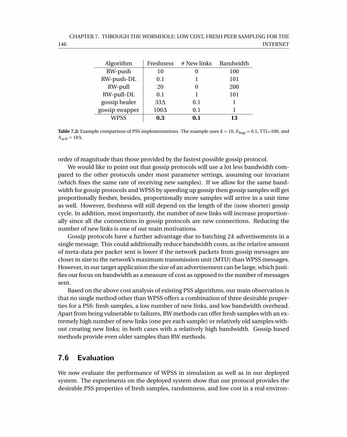
146
CHAPTER 7. THROUGH THE WORMHOLE: LOW COST, FRESH PEER SAMPLING FOR THE
INTERNET
Algorithm Freshness # New links BandwidthRW-push 10 0 100
RW-push-DL 0.1 1 101RW-pull 20 0 200
RW-pull-DL 0.1 1 101gossip healer 33∆ 0.1 1
gossip swapper 100∆ 0.1 1WPSS 0.3 0.1 13
Table 7.2: Example comparison of PSS implementations. The example uses k = 10, δhop = 0.1, TTL=100, and∆wh = 10∆.
order of magnitude than those provided by the fastest possible gossip protocol.We would like to point out that gossip protocols will use a lot less bandwidth com-
pared to the other protocols under most parameter settings, assuming our invariant(which fixes the same rate of receiving new samples). If we allow for the same band-width for gossip protocols and WPSS by speeding up gossip then gossip samples will getproportionally fresher, besides, proportionally more samples will arrive in a unit timeas well. However, freshness will still depend on the length of the (now shorter) gossipcycle. In addition, most importantly, the number of new links will increase proportion-ally since all the connections in gossip protocols are new connections. Reducing thenumber of new links is one of our main motivations.
Gossip protocols have a further advantage due to batching 2k advertisements in asingle message. This could additionally reduce bandwidth costs, as the relative amountof meta-data per packet sent is lower if the network packets from gossip messages arecloser in size to the network’s maximum transmission unit (MTU) than WPSS messages.However, in our target application the size of an advertisement can be large, which justi-fies our focus on bandwidth as a measure of cost as opposed to the number of messagessent.
Based on the above cost analysis of existing PSS algorithms, our main observation isthat no single method other than WPSS offers a combination of three desirable proper-ties for a PSS: fresh samples, a low number of new links, and low bandwidth overhead.Apart from being vulnerable to failures, RW methods can offer fresh samples with an ex-tremely high number of new links (one per each sample) or relatively old samples with-out creating new links; in both cases with a relatively high bandwidth. Gossip basedmethods provide even older samples than RW methods.
7.6 Evaluation
We now evaluate the performance of WPSS in simulation as well as in our deployedsystem. The experiments on the deployed system show that our protocol provides thedesirable PSS properties of fresh samples, randomness, and low cost in a real environ-
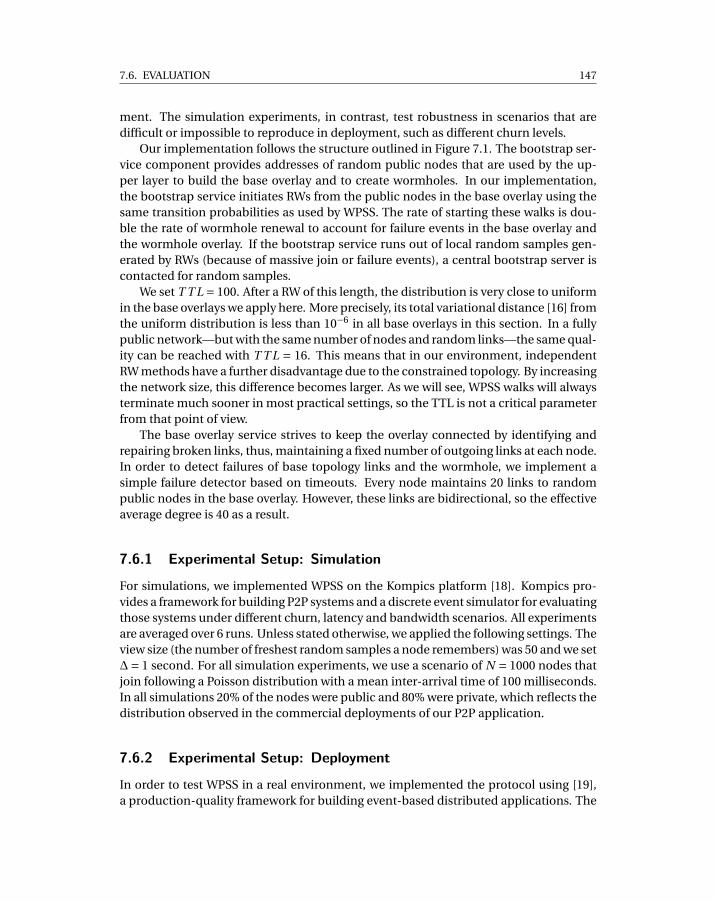
7.6. EVALUATION 147
ment. The simulation experiments, in contrast, test robustness in scenarios that aredifficult or impossible to reproduce in deployment, such as different churn levels.
Our implementation follows the structure outlined in Figure 7.1. The bootstrap ser-vice component provides addresses of random public nodes that are used by the up-per layer to build the base overlay and to create wormholes. In our implementation,the bootstrap service initiates RWs from the public nodes in the base overlay using thesame transition probabilities as used by WPSS. The rate of starting these walks is dou-ble the rate of wormhole renewal to account for failure events in the base overlay andthe wormhole overlay. If the bootstrap service runs out of local random samples gen-erated by RWs (because of massive join or failure events), a central bootstrap server iscontacted for random samples.
We set T T L = 100. After a RW of this length, the distribution is very close to uniformin the base overlays we apply here. More precisely, its total variational distance [16] fromthe uniform distribution is less than 10−6 in all base overlays in this section. In a fullypublic network—but with the same number of nodes and random links—the same qual-ity can be reached with T T L = 16. This means that in our environment, independentRW methods have a further disadvantage due to the constrained topology. By increasingthe network size, this difference becomes larger. As we will see, WPSS walks will alwaysterminate much sooner in most practical settings, so the TTL is not a critical parameterfrom that point of view.
The base overlay service strives to keep the overlay connected by identifying andrepairing broken links, thus, maintaining a fixed number of outgoing links at each node.In order to detect failures of base topology links and the wormhole, we implement asimple failure detector based on timeouts. Every node maintains 20 links to randompublic nodes in the base overlay. However, these links are bidirectional, so the effectiveaverage degree is 40 as a result.
7.6.1 Experimental Setup: Simulation
For simulations, we implemented WPSS on the Kompics platform [18]. Kompics pro-vides a framework for building P2P systems and a discrete event simulator for evaluatingthose systems under different churn, latency and bandwidth scenarios. All experimentsare averaged over 6 runs. Unless stated otherwise, we applied the following settings. Theview size (the number of freshest random samples a node remembers) was 50 and we set∆= 1 second. For all simulation experiments, we use a scenario of N = 1000 nodes thatjoin following a Poisson distribution with a mean inter-arrival time of 100 milliseconds.In all simulations 20% of the nodes were public and 80% were private, which reflects thedistribution observed in the commercial deployments of our P2P application.
7.6.2 Experimental Setup: Deployment
In order to test WPSS in a real environment, we implemented the protocol using [19],a production-quality framework for building event-based distributed applications. The
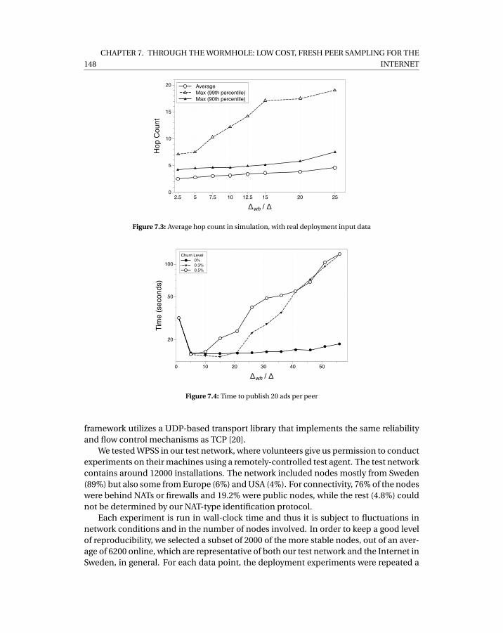
148
CHAPTER 7. THROUGH THE WORMHOLE: LOW COST, FRESH PEER SAMPLING FOR THE
INTERNET
AverageMax (99th percentile)Max (90th percentile)
Hop
Cou
nt
0
5
10
15
20
Δwh / Δ2.5 5 7.5 10 12.5 15 20 25
Figure 7.3: Average hop count in simulation, with real deployment input data
0%0.3%0.5%
Churn Level
Tim
e (s
econ
ds)
20
50
100
Δwh / Δ0 10 20 30 40 50
Figure 7.4: Time to publish 20 ads per peer
framework utilizes a UDP-based transport library that implements the same reliabilityand flow control mechanisms as TCP [20].
We tested WPSS in our test network, where volunteers give us permission to conductexperiments on their machines using a remotely-controlled test agent. The test networkcontains around 12000 installations. The network included nodes mostly from Sweden(89%) but also some from Europe (6%) and USA (4%). For connectivity, 76% of the nodeswere behind NATs or firewalls and 19.2% were public nodes, while the rest (4.8%) couldnot be determined by our NAT-type identification protocol.
Each experiment is run in wall-clock time and thus it is subject to fluctuations innetwork conditions and in the number of nodes involved. In order to keep a good levelof reproducibility, we selected a subset of 2000 of the more stable nodes, out of an aver-age of 6200 online, which are representative of both our test network and the Internet inSweden, in general. For each data point, the deployment experiments were repeated a
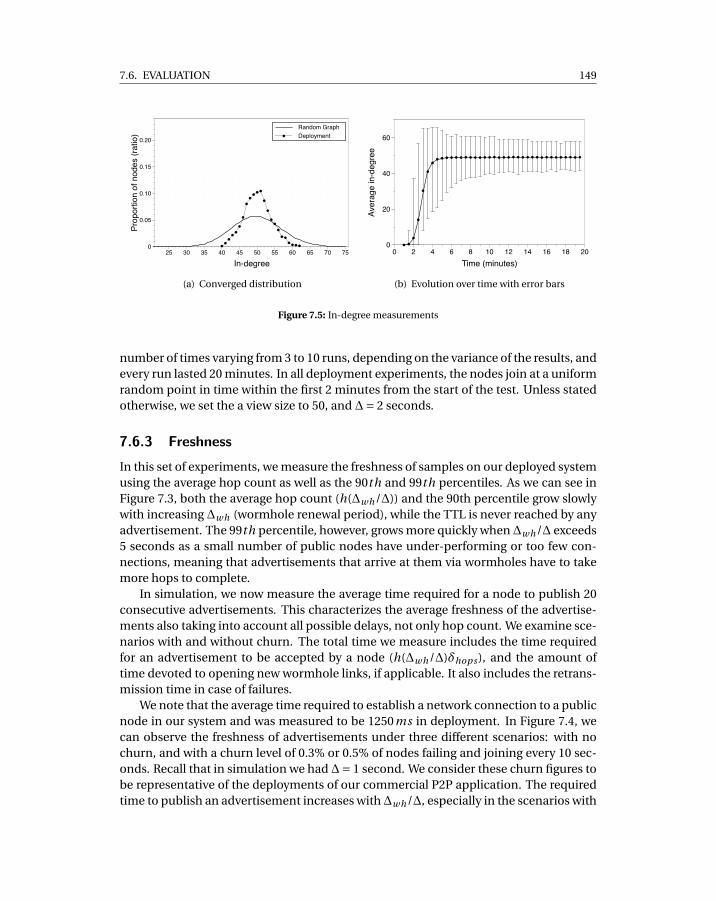
7.6. EVALUATION 149
Random GraphDeployment
Prop
ortio
n of
nod
es (r
atio
)
0
0.05
0.10
0.15
0.20
In-degree25 30 35 40 45 50 55 60 65 70 75
(a) Converged distribution
Aver
age
in-d
egre
e
0
20
40
60
Time (minutes)0 2 4 6 8 10 12 14 16 18 20
(b) Evolution over time with error bars
Figure 7.5: In-degree measurements
number of times varying from 3 to 10 runs, depending on the variance of the results, andevery run lasted 20 minutes. In all deployment experiments, the nodes join at a uniformrandom point in time within the first 2 minutes from the start of the test. Unless statedotherwise, we set the a view size to 50, and ∆= 2 seconds.
7.6.3 FreshnessIn this set of experiments, we measure the freshness of samples on our deployed systemusing the average hop count as well as the 90th and 99th percentiles. As we can see inFigure 7.3, both the average hop count (h(∆wh/∆)) and the 90th percentile grow slowlywith increasing ∆wh (wormhole renewal period), while the TTL is never reached by anyadvertisement. The 99th percentile, however, grows more quickly when∆wh/∆ exceeds5 seconds as a small number of public nodes have under-performing or too few con-nections, meaning that advertisements that arrive at them via wormholes have to takemore hops to complete.
In simulation, we now measure the average time required for a node to publish 20consecutive advertisements. This characterizes the average freshness of the advertise-ments also taking into account all possible delays, not only hop count. We examine sce-narios with and without churn. The total time we measure includes the time requiredfor an advertisement to be accepted by a node (h(∆wh/∆)δhops ), and the amount oftime devoted to opening new wormhole links, if applicable. It also includes the retrans-mission time in case of failures.
We note that the average time required to establish a network connection to a publicnode in our system and was measured to be 1250ms in deployment. In Figure 7.4, wecan observe the freshness of advertisements under three different scenarios: with nochurn, and with a churn level of 0.3% or 0.5% of nodes failing and joining every 10 sec-onds. Recall that in simulation we had∆= 1 second. We consider these churn figures tobe representative of the deployments of our commercial P2P application. The requiredtime to publish an advertisement increases with∆wh/∆, especially in the scenarios with
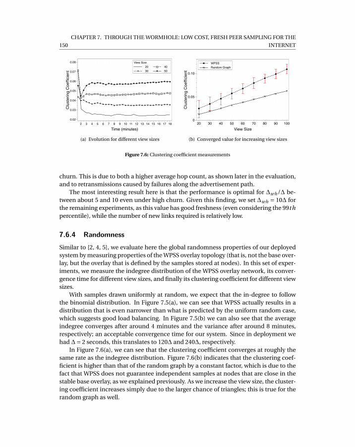
150
CHAPTER 7. THROUGH THE WORMHOLE: LOW COST, FRESH PEER SAMPLING FOR THE
INTERNET
2030
4050
View SizeC
lust
erin
g C
oeffi
cien
t
0.02
0.03
0.04
0.05
0.06
0.07
0.08
Time (minutes)2 3 4 5 6 7 8 9 10 11 12 13 14 15 16 17 18
(a) Evolution for different view sizes
WPSSRandom Graph
Clu
ster
ing
Coe
ffici
ent
0
0.05
0.10
View Size20 30 40 50 60 70 80 90 100
(b) Converged value for increasing view sizes
Figure 7.6: Clustering coefficient measurements
churn. This is due to both a higher average hop count, as shown later in the evaluation,and to retransmissions caused by failures along the advertisement path.
The most interesting result here is that the performance is optimal for ∆wh/∆ be-tween about 5 and 10 even under high churn. Given this finding, we set ∆wh = 10∆ forthe remaining experiments, as this value has good freshness (even considering the 99thpercentile), while the number of new links required is relatively low.
7.6.4 RandomnessSimilar to [2, 4, 5], we evaluate here the global randomness properties of our deployedsystem by measuring properties of the WPSS overlay topology (that is, not the base over-lay, but the overlay that is defined by the samples stored at nodes). In this set of exper-iments, we measure the indegree distribution of the WPSS overlay network, its conver-gence time for different view sizes, and finally its clustering coefficient for different viewsizes.
With samples drawn uniformly at random, we expect that the in-degree to followthe binomial distribution. In Figure 7.5(a), we can see that WPSS actually results in adistribution that is even narrower than what is predicted by the uniform random case,which suggests good load balancing. In Figure 7.5(b) we can also see that the averageindegree converges after around 4 minutes and the variance after around 8 minutes,respectively; an acceptable convergence time for our system. Since in deployment wehad ∆= 2 seconds, this translates to 120∆ and 240∆, respectively.
In Figure 7.6(a), we can see that the clustering coefficient converges at roughly thesame rate as the indegree distribution. Figure 7.6(b) indicates that the clustering coef-ficient is higher than that of the random graph by a constant factor, which is due to thefact that WPSS does not guarantee independent samples at nodes that are close in thestable base overlay, as we explained previously. As we increase the view size, the cluster-ing coefficient increases simply due to the larger chance of triangles; this is true for therandom graph as well.
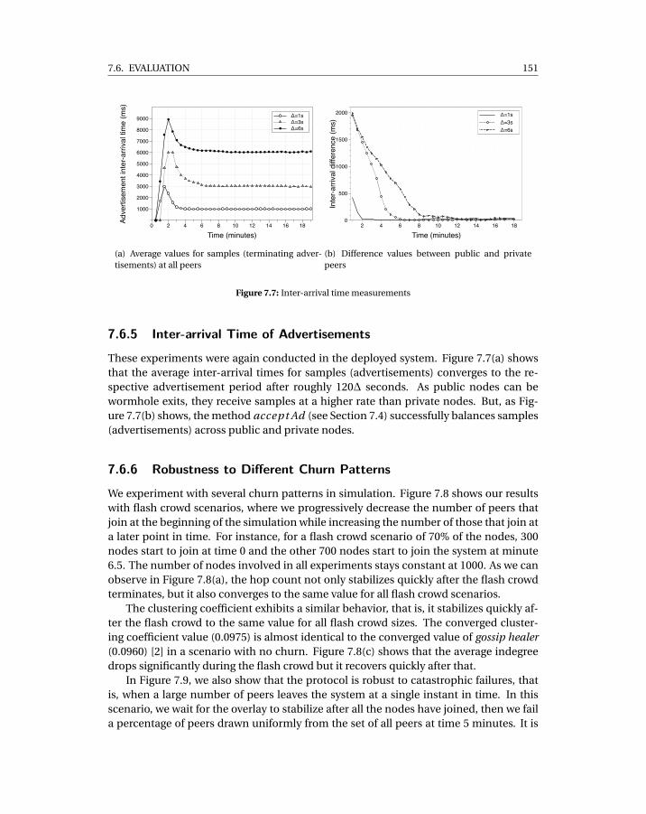
7.6. EVALUATION 151
Δ=1sΔ=3sΔ=6s
Adve
rtise
men
t int
er-a
rriva
l tim
e (m
s)
1000
2000
3000
4000
5000
6000
7000
8000
9000
Time (minutes)0 2 4 6 8 10 12 14 16 18
(a) Average values for samples (terminating adver-tisements) at all peers
Δ=1sΔ=3sΔ=6s
Inte
r-arri
val d
iffer
ence
(ms)
0
500
1000
1500
2000
Time (minutes)2 4 6 8 10 12 14 16 18
(b) Difference values between public and privatepeers
Figure 7.7: Inter-arrival time measurements
7.6.5 Inter-arrival Time of Advertisements
These experiments were again conducted in the deployed system. Figure 7.7(a) showsthat the average inter-arrival times for samples (advertisements) converges to the re-spective advertisement period after roughly 120∆ seconds. As public nodes can bewormhole exits, they receive samples at a higher rate than private nodes. But, as Fig-ure 7.7(b) shows, the method accept Ad (see Section 7.4) successfully balances samples(advertisements) across public and private nodes.
7.6.6 Robustness to Different Churn Patterns
We experiment with several churn patterns in simulation. Figure 7.8 shows our resultswith flash crowd scenarios, where we progressively decrease the number of peers thatjoin at the beginning of the simulation while increasing the number of those that join ata later point in time. For instance, for a flash crowd scenario of 70% of the nodes, 300nodes start to join at time 0 and the other 700 nodes start to join the system at minute6.5. The number of nodes involved in all experiments stays constant at 1000. As we canobserve in Figure 7.8(a), the hop count not only stabilizes quickly after the flash crowdterminates, but it also converges to the same value for all flash crowd scenarios.
The clustering coefficient exhibits a similar behavior, that is, it stabilizes quickly af-ter the flash crowd to the same value for all flash crowd sizes. The converged cluster-ing coefficient value (0.0975) is almost identical to the converged value of gossip healer(0.0960) [2] in a scenario with no churn. Figure 7.8(c) shows that the average indegreedrops significantly during the flash crowd but it recovers quickly after that.
In Figure 7.9, we also show that the protocol is robust to catastrophic failures, thatis, when a large number of peers leaves the system at a single instant in time. In thisscenario, we wait for the overlay to stabilize after all the nodes have joined, then we faila percentage of peers drawn uniformly from the set of all peers at time 5 minutes. It is
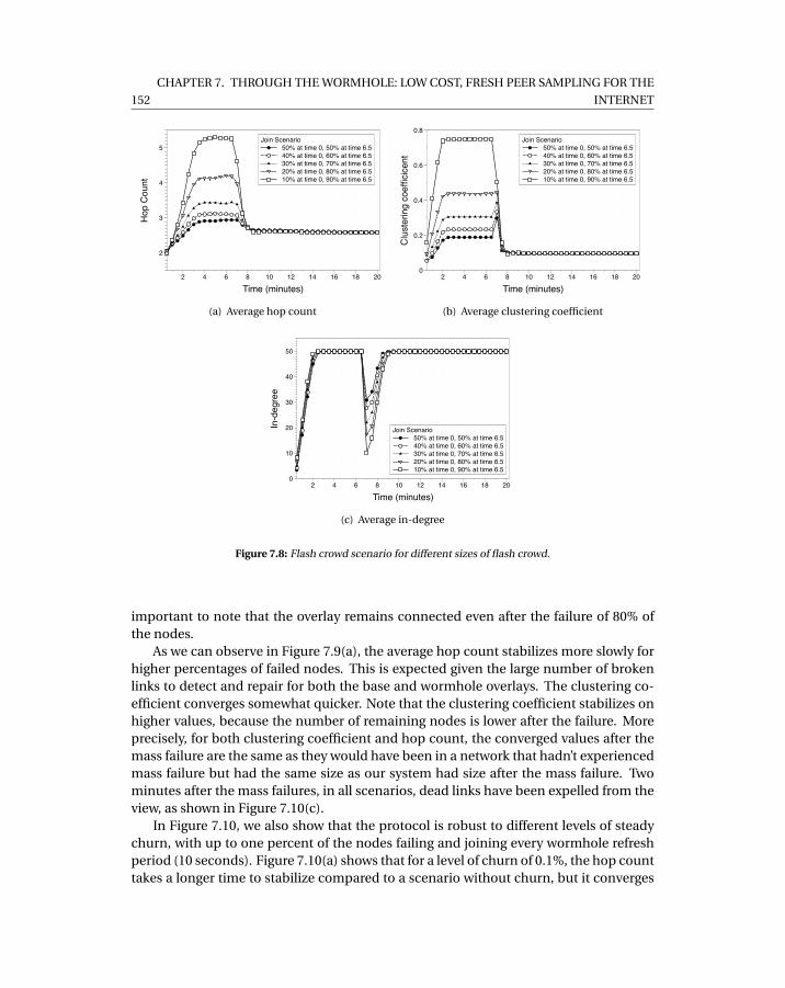
152
CHAPTER 7. THROUGH THE WORMHOLE: LOW COST, FRESH PEER SAMPLING FOR THE
INTERNET
50% at time 0, 50% at time 6.540% at time 0, 60% at time 6.530% at time 0, 70% at time 6.520% at time 0, 80% at time 6.510% at time 0, 90% at time 6.5
Join ScenarioH
op C
ount
2
3
4
5
Time (minutes)2 4 6 8 10 12 14 16 18 20
(a) Average hop count
50% at time 0, 50% at time 6.540% at time 0, 60% at time 6.530% at time 0, 70% at time 6.520% at time 0, 80% at time 6.510% at time 0, 90% at time 6.5
Join Scenario
Clu
ster
ing
coef
ficic
ent
0
0.2
0.4
0.6
0.8
Time (minutes)2 4 6 8 10 12 14 16 18 20
(b) Average clustering coefficient
50% at time 0, 50% at time 6.540% at time 0, 60% at time 6.530% at time 0, 70% at time 6.520% at time 0, 80% at time 6.510% at time 0, 90% at time 6.5
Join ScenarioIn-d
egre
e
0
10
20
30
40
50
Time (minutes)2 4 6 8 10 12 14 16 18 20
(c) Average in-degree
Figure 7.8: Flash crowd scenario for different sizes of flash crowd.
important to note that the overlay remains connected even after the failure of 80% ofthe nodes.
As we can observe in Figure 7.9(a), the average hop count stabilizes more slowly forhigher percentages of failed nodes. This is expected given the large number of brokenlinks to detect and repair for both the base and wormhole overlays. The clustering co-efficient converges somewhat quicker. Note that the clustering coefficient stabilizes onhigher values, because the number of remaining nodes is lower after the failure. Moreprecisely, for both clustering coefficient and hop count, the converged values after themass failure are the same as they would have been in a network that hadn’t experiencedmass failure but had the same size as our system had size after the mass failure. Twominutes after the mass failures, in all scenarios, dead links have been expelled from theview, as shown in Figure 7.10(c).
In Figure 7.10, we also show that the protocol is robust to different levels of steadychurn, with up to one percent of the nodes failing and joining every wormhole refreshperiod (10 seconds). Figure 7.10(a) shows that for a level of churn of 0.1%, the hop counttakes a longer time to stabilize compared to a scenario without churn, but it converges
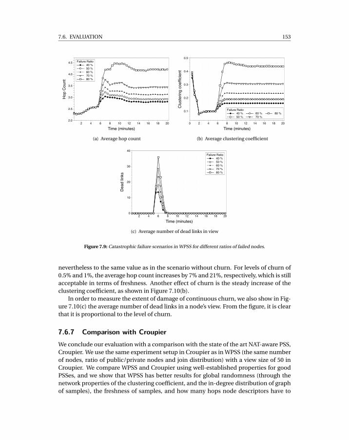
7.6. EVALUATION 153
40 %50 %60 %70 %80 %
Failure RatioH
op C
ount
2.0
2.5
3.0
3.5
4.0
4.5
Time (minutes)2 4 6 8 10 12 14 16 18 20
(a) Average hop count
40 %50 %
60 %70 %
80 %Failure Ratio
Clu
ster
ing
coef
ficie
nt
0.1
0.2
0.3
0.4
0.5
Time (minutes)0 2 4 6 8 10 12 14 16 18 20
(b) Average clustering coefficient
40 %50 %60 %70 %80 %
Failure Ratio
Dea
d lin
ks
0
10
20
30
40
Time (minutes)2 4 6 8 10 12 14 16 18 20
(c) Average number of dead links in view
Figure 7.9: Catastrophic failure scenarios in WPSS for different ratios of failed nodes.
nevertheless to the same value as in the scenario without churn. For levels of churn of0.5% and 1%, the average hop count increases by 7% and 21%, respectively, which is stillacceptable in terms of freshness. Another effect of churn is the steady increase of theclustering coefficient, as shown in Figure 7.10(b).
In order to measure the extent of damage of continuous churn, we also show in Fig-ure 7.10(c) the average number of dead links in a node’s view. From the figure, it is clearthat it is proportional to the level of churn.
7.6.7 Comparison with CroupierWe conclude our evaluation with a comparison with the state of the art NAT-aware PSS,Croupier. We use the same experiment setup in Croupier as in WPSS (the same numberof nodes, ratio of public/private nodes and join distribution) with a view size of 50 inCroupier. We compare WPSS and Croupier using well-established properties for goodPSSes, and we show that WPSS has better results for global randomness (through thenetwork properties of the clustering coefficient, and the in-degree distribution of graphof samples), the freshness of samples, and how many hops node descriptors have to
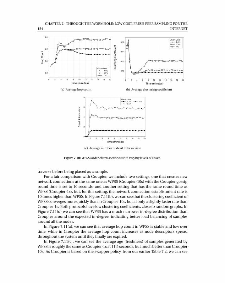
154
CHAPTER 7. THROUGH THE WORMHOLE: LOW COST, FRESH PEER SAMPLING FOR THE
INTERNET
0.1%0.5%1%
Churn level
Hop
Cou
nt
2.0
2.5
3.0
3.5
Time (minutes)0 2 4 6 8 10 12 14 16 18 20
(a) Average hop count
0.1%0.5%1%
Churn Level
Clu
ster
ing
Coe
ffici
ent
0.10
0.12
0.14
0.16
Time (minutes)0 2 4 6 8 10 12 14 16 18 20
(b) Average clustering coefficient
0.1%0.5%
1%Churn Level
Dea
d lin
ks in
vie
w
0
2
4
6
8
Time (minutes)2 4 6 8 10 12 14 16 18 20
(c) Average number of dead links in view
Figure 7.10: WPSS under churn scenarios with varying levels of churn.
traverse before being placed as a sample.For a fair comparison with Croupier, we include two settings, one that creates new
network connections at the same rate as WPSS (Croupier-10s) with the Croupier gossipround time is set to 10 seconds, and another setting that has the same round time asWPSS (Croupier-1s), but, for this setting, the network connection establishment rate is10 times higher than WPSS. In Figure 7.11(b), we can see that the clustering coefficient ofWPSS converges more quickly than in Croupier-10s, but at only a slightly faster rate thanCroupier-1s. Both protocols have low clustering coefficients, close to random graphs. InFigure 7.11(d) we can see that WPSS has a much narrower in-degree distribution thanCroupier around the expected in-degree, indicating better load balancing of samplesaround all the nodes.
In Figure 7.11(a), we can see that average hop count in WPSS is stable and low overtime, while in Croupier the average hop count increases as node descriptors spreadthroughout the system until they finally are expired.
In Figure 7.11(c), we can see the average age (freshness) of samples generated byWPSS is roughly the same as Croupier-1s at 11.5 seconds, but much better than Croupier-10s. As Croupier is based on the swapper policy, from our earlier Table 7.2, we can see
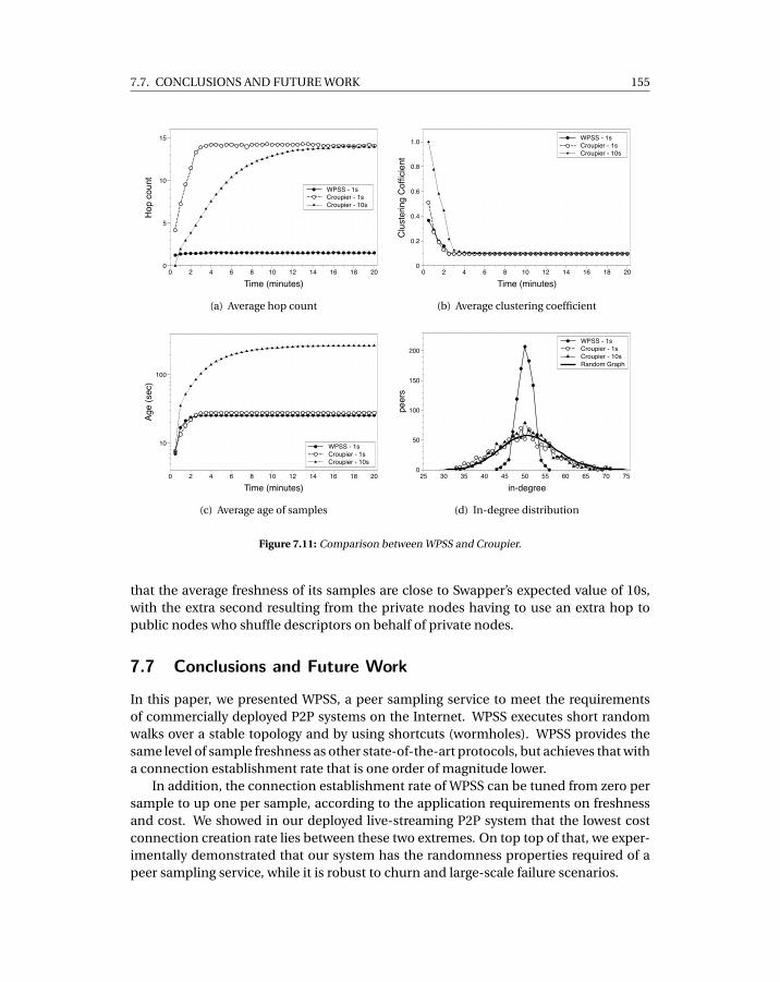
7.7. CONCLUSIONS AND FUTURE WORK 155
WPSS - 1sCroupier - 1sCroupier - 10s
Hop
cou
nt
0
5
10
15
Time (minutes)0 2 4 6 8 10 12 14 16 18 20
(a) Average hop count
WPSS - 1sCroupier - 1sCroupier - 10s
Clu
ster
ing
Cof
ficie
nt
0
0.2
0.4
0.6
0.8
1.0
Time (minutes)0 2 4 6 8 10 12 14 16 18 20
(b) Average clustering coefficient
WPSS - 1sCroupier - 1sCroupier - 10s
Age
(sec
)
10
100
Time (minutes)0 2 4 6 8 10 12 14 16 18 20
(c) Average age of samples
WPSS - 1sCroupier - 1sCroupier - 10sRandom Graph
peer
s
0
50
100
150
200
in-degree25 30 35 40 45 50 55 60 65 70 75
(d) In-degree distribution
Figure 7.11: Comparison between WPSS and Croupier.
that the average freshness of its samples are close to Swapper’s expected value of 10s,with the extra second resulting from the private nodes having to use an extra hop topublic nodes who shuffle descriptors on behalf of private nodes.
7.7 Conclusions and Future Work
In this paper, we presented WPSS, a peer sampling service to meet the requirementsof commercially deployed P2P systems on the Internet. WPSS executes short randomwalks over a stable topology and by using shortcuts (wormholes). WPSS provides thesame level of sample freshness as other state-of-the-art protocols, but achieves that witha connection establishment rate that is one order of magnitude lower.
In addition, the connection establishment rate of WPSS can be tuned from zero persample to up one per sample, according to the application requirements on freshnessand cost. We showed in our deployed live-streaming P2P system that the lowest costconnection creation rate lies between these two extremes. On top top of that, we exper-imentally demonstrated that our system has the randomness properties required of apeer sampling service, while it is robust to churn and large-scale failure scenarios.
156
CHAPTER 7. THROUGH THE WORMHOLE: LOW COST, FRESH PEER SAMPLING FOR THE
INTERNET
While we have designed WPSS for the Internet, we believe it is general enough towork over any type of stable base overlay (given a high enough TTL for RWs) and anysubset of nodes can act as wormholes. As part of our future work, we will consider ap-plying WPSS to mobile and sensor networks, and overlay networks without NATs or fire-walls.
7.8 References
[1] Gunnar Kreitz and Fredrik Niemela. Spotify – large scale, low latency, P2P Music-on-Demand streaming. In Tenth IEEE International Conference on Peer-to-PeerComputing (P2P’10). IEEE, August 2010. ISBN 978-1-4244-7140-9.
[2] Márk Jelasity, Spyros Voulgaris, Rachid Guerraoui, Anne-Marie Kermarrec, andMaarten van Steen. Gossip-based peer sampling. ACM Transactions on ComputerSystems, 25(3):8, August 2007.
[3] Daniel Stutzbach, Reza Rejaie, Nick Duffield, Subhabrata Sen, and Walter Willinger.On unbiased sampling for unstructured peer-to-peer networks. IEEE/ACM Trans-actions on Networking, 17(2):377–390, April 2009.
[4] Amir H. Payberah, Jim Dowling, and Seif Haridi. Gozar: Nat-friendly peer sam-pling with one-hop distributed nat traversal. In Pascal Felber and Romain Rouvoy,editors, DAIS, Lecture Notes in Computer Science, 2011.
[5] Jim Dowling and Amir H. Payberah. Shuffling with a croupier: Nat-aware peer-sampling. ICDCS, 0:102–111, 2012. ISSN 1063-6927.
[6] Anne-Marie Kermarrec, Alessio Pace, Vivien Quema, and Valerio Schiavoni. NAT-resilient gossip peer sampling. In Proc. 29th IEEE Intl. Conf. on Distributed Com-puting Systems, pages 360–367. IEEE Comp. Soc., 2009.
[7] Saikat Guha, Neil Daswani, and Ravi Jain. An Experimental Study of the SkypePeer-to-Peer VoIP System. In Proceedings of IPTPS, pages 1–6, Santa Barbara, CA,February 2006.
[8] A. Bergkvist, D.C. Burnett, C. Jennings, and A. Narayanan. Webrtc 1.0: Real-timecommunication between browsers. In W3C Working Draft 21 August 2012, 2012.URL http://www.w3.org/TR/webrtc/.
[9] Roberto Roverso, Sameh El-Ansary, and Seif Haridi. Smoothcache: Http-livestreaming goes peer-to-peer. Lecture Notes in Computer Science, 7290:29–43, 2012.
[10] Ittay Eyal, Idit Keidar, and Raphael Rom. Limosense – live monitoring in dynamicsensor networks. In Algorithms for Sensor Systems, volume 7111 of LNCS, pages72–85. Springer, 2012.

7.8. REFERENCES 157
[11] Spyros Voulgaris, Daniela Gavidia, and Maarten Van Steen. Cyclon: Inexpensivemembership management for unstructured p2p overlays. Journal of Network andSystems Management, 13:2005, 2005.
[12] Ayalvadi J. Ganesh, Anne-Marie Kermarrec, and Laurent Massoulié. Peer-to-peermembership management for gossip-based protocols. IEEE Transactions on Com-puters, 52(2), February 2003.
[13] J. Leitão, R. van Renesse, and L. Rodrigues. Balancing gossip exchanges in net-works with firewalls. In Michael J. Freedman and Arvind Krishnamurthy, editors,Proceedings of the 9th International Workshop on Peer-to-Peer Systems (IPTPS ’10),page 7. USENIX, 2010.
[14] Roberto Roverso, Sameh El-Ansary, and Seif Haridi. NATCracker: NAT Combina-tions Matter. In Proc. of 18th International Conference on Computer Communica-tions and Networks, ICCCN ’09, SF, CA, USA, 2009. IEEE Computer Society. ISBN978-1-4244-4581-3.
[15] Daniel Stutzbach, Reza Rejaie, Nick Duffield, Subhabrata Sen, and Walter Willinger.On unbiased sampling for unstructured peer-to-peer networks. IEEE/ACM Trans.Netw., 17(2):377–390, April 2009. ISSN 1063-6692.
[16] László Lovász and Peter Winkler. Mixing of random walks and other diffusions ona graph. In P. Rowlinson, editor, Surveys in Combinatorics, volume 218 of LondonMath. Soc. Lecture Notes Series, pages 119–154. Cambridge University Press, 1995.URL http://research.microsoft.com/users/lovasz/survey.htm.
[17] Siddhartha Chib and Edward Greenberg. Understanding the metropolis-hastingsalgorithm. The American Statistician, 49(4):327–335.
[18] Cosmin Arad, Jim Dowling, and Seif Haridi. Message-passing concurrency for scal-able, stateful, reconfigurable middleware. In ACM/IFIP/USENIX International Mid-dleware Conference, 2012.
[19] Roberto Roverso, Sameh El-Ansary, Alexandros Gkogkas, and Seif Haridi. Mesmer-izer: a effective tool for a complete peer-to-peer software development life-cycle.In SIMUTools ’11, 2011. ISBN 978-1-936968-00-8.
[20] Riccardo Reale, Roberto Roverso, Sameh El-Ansary, and Seif Haridi. DTL: DynamicTransport Library for Peer-To-Peer Applications. In In Proc. of the 12th Interna-tional Conference on Distributed Computing and Networking, ICDCN, Jan 2012.


PART V
Peer-To-Peer Streaming AgentDesign
159

CH
AP
TE
R
8SMOOTHCACHE: HTTP-LIVE STREAMING
GOES PEER-TO-PEER

8.1. INTRODUCTION 163
SmoothCache: HTTP-Live Streaming GoesPeer-To-Peer
Roberto Roverso1,2, Sameh El-Ansary1 and Seif Haridi2
1Peerialism ABStockholm, Sweden
[roberto,sameh]@peerialism.com
2KTH - Royal Institute of TechnologyStockholm, Sweden[haridi]@kth.se
Abstract
In this paper, we present SmoothCache, a peer-to-peer live video streaming(P2PLS) system. The novelty of SmoothCache is threefold: i ) It is the first P2PLSsystem that is built to support the relatively-new approach of using HTTP as thetransport protocol for live content, i i ) The system supports both single and multi-bitrate streaming modes of operation, and i i i ) In Smoothcache, we make use ofrecent advances in application-layer dynamic congestion control to manage prior-ities of transfers according to their urgency. We start by explaining why the HTTPlive streaming semantics render many of the existing assumptions used in P2PLSprotocols obsolete. Afterwards, we present our design starting with a baseline P2Pcaching model. We, then, show a number of optimizations related to aspects such asneighborhood management, uploader selection and proactive caching. Finally, wepresent our evaluation conducted on a real yet instrumented test network. Our re-sults show that we can achieve substantial traffic savings on the source of the streamwithout major degradation in user experience.
8.1 Introduction
Peer-to-peer live streaming (P2PLS) is a problem in the Peer-To-Peer (P2P) networkingfield that has been tackled for quite some time on both the academic and industrialfronts. The typical goal is to utilize the upload bandwidth of hosts consuming a cer-tain live content to offload the bandwidth of the broadcasting origin. On the industrial
164 CHAPTER 8. SMOOTHCACHE: HTTP-LIVE STREAMING GOES PEER-TO-PEER
front, we find successful large deployments where knowledge about their technical ap-proaches is rather limited. Exceptions include systems described by their authors likeCoolstreaming [1] or inferred by reverse engineering like PPlive [2] and TVAnts [3]. Onthe academic front, there have been several attempts to try to estimate theoretical limitsin terms of optimality of bandwidth utilization [4][5] or delay [6].
Traditionally, HTTP has been utilized for progressive download streaming, cham-pioned by popular Video-On-Demand (VoD) solutions such as Netflix [7] and Apple’siTunes movie store. However, lately, adaptive HTTP-based streaming protocols becamethe main technology for live streaming as well. All companies who have a major sayin the market including Microsoft, Adobe and Apple have adopted HTTP-streaming asthe main approach for live broadcasting. This shift to HTTP has been driven by a num-ber of advantages such as the following: i ) Routers and firewalls are more permissive toHTTP traffic compared to the RTSP/RTP i i ) HTTP caching for real-time generated me-dia is straight-forward like any traditional web-content i i i ) The Content DistributionNetworks (CDNs) business is much cheaper when dealing with HTTP downloads [8].
The first goal of this paper is to describe the shift from the RTSP/RTP model to theHTTP-live model (Section 8.2). This, in order to detail the impact of the same on thedesign of P2P live streaming protocols (Section 8.3). A point which we find rather ne-glected in the research community (Section 8.4). We argue that this shift has renderedmany of the classical assumptions made in the current state-of-the-art literature obso-lete. For all practical purposes, any new P2PLS algorithm irrespective of its theoreti-cal soundness, won’t be deployable if it does not take into account the realities of themainstream broadcasting ecosystem around it. The issue becomes even more topicalas we observe a trend in standardizing HTTP live [9] streaming and embedding it in allbrowsers together with HTML5, which is already the case in browsers like Apple’s Safari.
The second goal of this paper is to present a P2PLS protocol that is compatible withHTTP live streaming for not only one bitrate but that is fully compatible with the con-cept of adaptive bitrate, where a stream is broadcast with multiple bitrates simultane-ously to make it available for a range of viewers with variable download capacities (Sec-tion 8.5).
The last goal of this paper is to describe a number of optimizations of our P2PLSprotocol concerning neighborhood management, uploader selection and peer transferwhich can deliver a significant amount of traffic savings on the source of the stream(Section 8.6 and 8.7). Experimental results of our approach show that this result comesat almost no cost in terms of quality of user experience (Section 8.8).
8.2 The Shift from RTP/RTSP to HTTP
In the traditional RTSP/RTP model, the player uses RTSP as the signalling protocol torequest the playing of the stream from a streaming server. The player enters a receiveloop while the server enters a send loop where stream fragments are delivered to the re-ceiver using the RTP protocol over UDP. The interaction between the server and playeris stateful. The server makes decisions about which fragment is sent next based on ac-
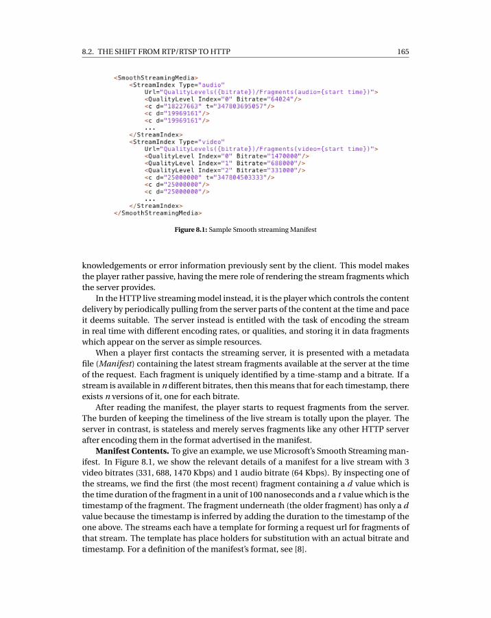
8.2. THE SHIFT FROM RTP/RTSP TO HTTP 165
Figure 8.1: Sample Smooth streaming Manifest
knowledgements or error information previously sent by the client. This model makesthe player rather passive, having the mere role of rendering the stream fragments whichthe server provides.
In the HTTP live streaming model instead, it is the player which controls the contentdelivery by periodically pulling from the server parts of the content at the time and paceit deems suitable. The server instead is entitled with the task of encoding the streamin real time with different encoding rates, or qualities, and storing it in data fragmentswhich appear on the server as simple resources.
When a player first contacts the streaming server, it is presented with a metadatafile (Manifest) containing the latest stream fragments available at the server at the timeof the request. Each fragment is uniquely identified by a time-stamp and a bitrate. If astream is available in n different bitrates, then this means that for each timestamp, thereexists n versions of it, one for each bitrate.
After reading the manifest, the player starts to request fragments from the server.The burden of keeping the timeliness of the live stream is totally upon the player. Theserver in contrast, is stateless and merely serves fragments like any other HTTP serverafter encoding them in the format advertised in the manifest.
Manifest Contents. To give an example, we use Microsoft’s Smooth Streaming man-ifest. In Figure 8.1, we show the relevant details of a manifest for a live stream with 3video bitrates (331, 688, 1470 Kbps) and 1 audio bitrate (64 Kbps). By inspecting one ofthe streams, we find the first (the most recent) fragment containing a d value which isthe time duration of the fragment in a unit of 100 nanoseconds and a t value which is thetimestamp of the fragment. The fragment underneath (the older fragment) has only a dvalue because the timestamp is inferred by adding the duration to the timestamp of theone above. The streams each have a template for forming a request url for fragments ofthat stream. The template has place holders for substitution with an actual bitrate andtimestamp. For a definition of the manifest’s format, see [8].
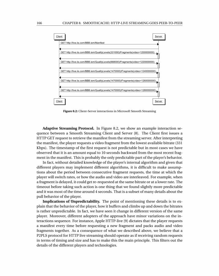
166 CHAPTER 8. SMOOTHCACHE: HTTP-LIVE STREAMING GOES PEER-TO-PEER
Figure 8.2: Client-Server interactions in Microsoft Smooth Streaming
Adaptive Streaming Protocol. In Figure 8.2, we show an example interaction se-quence between a Smooth Streaming Client and Server [8]. The Client first issues aHTTP GET request to retrieve the manifest from the streaming server. After interpretingthe manifest, the player requests a video fragment from the lowest available bitrate (331Kbps). The timestamp of the first request is not predictable but in most cases we haveobserved that it is an amount equal to 10 seconds backward from the most recent frag-ment in the manifest. This is probably the only predictable part of the player’s behavior.
In fact, without detailed knowledge of the player’s internal algorithm and given thatdifferent players may implement different algorithms, it is difficult to make assump-tions about the period between consecutive fragment requests, the time at which theplayer will switch rates, or how the audio and video are interleaved. For example, whena fragment is delayed, it could get re-requested at the same bitrate or at a lower rate. Thetimeout before taking such action is one thing that we found slightly more predictableand it was most of the time around 4 seconds. That is a subset of many details about thepull behavior of the player.
Implications of Unpredictability. The point of mentioning these details is to ex-plain that the behavior of the player, how it buffers and climbs up and down the bitratesis rather unpredictable. In fact, we have seen it change in different version of the sameplayer. Moreover, different adopters of the approach have minor variations on the in-teractions sequence. For instance, Apple HTTP-live [9] dictates that the player requestsa manifest every time before requesting a new fragment and packs audio and videofragments together. As a consequence of what we described above, we believe that aP2PLS protocol for HTTP live streaming should operate as if receiving random requestsin terms of timing and size and has to make this the main principle. This filters out thedetails of the different players and technologies.
8.3. IMPACT OF THE SHIFT ON P2PLS ALGORITHMS 167
8.3 Impact of the Shift on P2PLS Algorithms
Traditionally, the typical setup for a P2PLS agent is to sit between the streaming serverand the player as a local proxy offering the player the same protocol as the streamingserver. In such a setup, the P2PLS agent would do its best, exploiting the peer-to-peeroverlay, to deliver pieces in time and in the right order for the player. Thus, the P2PLSagent is the one driving the streaming process and keeping an active state about whichvideo or audio fragment should be delivered next, whereas the player blindly renderswhat it is supplied with. Given the assumption of a passive player, it is easy to envisagethe P2PLS algorithm skipping for instance fragments according to the playback dead-line, i.e. discarding data that comes too late for rendering. In this kind of situation, theplayer is expected to skip the missing data by fast-forwarding or blocking for few in-stants and then start the playback again. This type of behavior towards the player is anintrinsic property of many of the most mature P2PLS system designs and analyses suchas [1, 6, 10].
In contrast to that, a P2PLS agent for HTTP live streaming can not rely on the sameoperational principles. There is no freedom in skipping pieces and deciding what is tobe delivered to the player. The P2PLS agent has to obey the player’s request for frag-ments from the P2P network and the speed at which this is accomplished affects theplayer’s next action. From our experience, delving in the path of trying to reverse engi-neer the player behavior and integrating that in the P2P protocol is some kind of blackart based on trial-and-error and will result into very complicated and extremely version-specific customizations. Essentially, any P2PLS scheduling algorithm that assumes thatit has control over which data should be delivered to the player is rather inapplicable toHTTP live streaming.
8.4 Related Work
We are not aware of any work that has explicitly articulated the impact of the shift toHTTP on the P2P live streaming algorithms. However, a more relevant topic to look atis the behavior of the HTTP-based live players. Akhshabi et. al [11], provide a recentdissection of the behavior of three such players under different bandwidth variationscenarios. It is however clear from their analysis that the bitrate switching mechanics ofthe considered players are still in early stages of development. In particular, it is shownthat throughput fluctuations still cause either significant buffering or unnecessary bi-trate reductions. On top of that, it is shown how all the logic implemented in the HTTP-live players is tailored to TCP’s behavior, as the one suggested in [12]. That in order tocompensate throughput variations caused by TCP’s congestion control and potentiallylarge retransmission delays. In the case of a P2PLS agent acting as proxy, it is then ofparamount importance to not interfere with such adaptation patterns.
We believe, given the presented approaches, the most related work is the P2P cachingnetwork LiveSky [13]. We share in common the fact of trying to establish a P2P CDN.However, LiveSky does not present any solution for supporting HTTP live streaming.
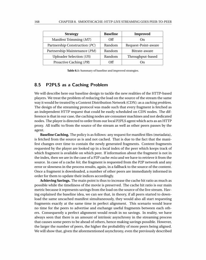
168 CHAPTER 8. SMOOTHCACHE: HTTP-LIVE STREAMING GOES PEER-TO-PEER
Strategy Baseline Improved
Manifest Trimming (MT) Off On
Partnership Construction (PC) Random Request-Point-aware
Partnership Maintenance (PM) Random Bitrate-aware
Uploader Selection (US) Random Throughput-based
Proactive Caching (PR) Off On
Table 8.1: Summary of baseline and improved strategies.
8.5 P2PLS as a Caching Problem
We will describe here our baseline design to tackle the new realities of the HTTP-basedplayers. We treat the problem of reducing the load on the source of the stream the sameway it would be treated by a Content Distribution Network (CDN): as a caching problem.The design of the streaming protocol was made such that every fragment is fetched asan independent HTTP request that could be easily scheduled on CDN nodes. The dif-ference is that in our case, the caching nodes are consumer machines and not dedicatednodes. The player is directed to order from our local P2PLS agent which acts as an HTTPproxy. All traffic to/from the source of the stream as well as other peers passes by theagent.
Baseline Caching. The policy is as follows: any request for manifest files (metadata),is fetched from the source as is and not cached. That is due to the fact that the mani-fest changes over time to contain the newly generated fragments. Content fragmentsrequested by the player are looked up in a local index of the peer which keeps track ofwhich fragment is available on which peer. If information about the fragment is not inthe index, then we are in the case of a P2P cache miss and we have to retrieve it from thesource. In case of a cache hit, the fragment is requested from the P2P network and anyerror or slowness in the process results, again, in a fallback to the source of the content.Once a fragment is downloaded, a number of other peers are immediately informed inorder for them to update their indices accordingly.
Achieving Savings. The main point is thus to increase the cache hit ratio as much aspossible while the timeliness of the movie is preserved. The cache hit ratio is our mainmetric because it represents savings from the load on the source of the live stream. Hav-ing explained the baseline idea, we can see that, in theory, if all peers started to down-load the same uncached manifest simultaneously, they would also all start requestingfragments exactly at the same time in perfect alignment. This scenario would leaveno time for the peers to advertise and exchange useful fragments between each oth-ers. Consequently a perfect alignment would result in no savings. In reality, we havealways seen that there is an amount of intrinsic asynchrony in the streaming processthat causes some peers to be ahead of others, hence making savings possible. However,the larger the number of peers, the higher the probability of more peers being aligned.We will show that, given the aforementioned asynchrony, even the previously described
8.6. BEYOND BASELINE CACHING 169
baseline design can achieve significant savings.Our target savings are relative to the number of peers. That is we do not target
achieving a constant load on the source of the stream irrespective of the number ofusers, which would lead to loss of timeliness. Instead, we aim to save a substantialpercentage of all source traffic by offloading that percentage to the P2P network. Theattractiveness of that model from a business perspective has been verified with contentowners who nowadays buy CDN services.
8.6 Beyond Baseline Caching
We give here a description of some of the important techniques that are crucial to theoperation of the P2PLS agent. For each such technique we provide what we think is thesimplest way to realize it as well as improvements if we were able to identify any. Thetechniques are summarized in Table 1.
Manifest Manipulation. One improvement particularly applicable in Microsoft’sSmooth streaming but that could be extended to all other technologies is manifest ma-nipulation. As explained in Section 8.2, the server sends a manifest containing a list ofthe most recent fragments available at the streaming server. The point of that is to availto the player some data in case the user decides to jump back in time. Minor trimmingto hide the most recent fragments from some peers places them behind others. We usethat technique to push peers with high upload bandwidth slightly ahead of others be-cause they have they can be more useful to the network. We are careful not to abuse thistoo much, otherwise peers would suffer a high delay from live playing point, so we limitit to a maximum of 4 seconds. It is worth noting here that we do a quick bandwidth mea-surement for peers upon admission to the network, mainly, for statistical purposes butwe do not depend on this measurement except during the optional trimming process.
Neighborhood & Partnership Construction. We use a tracker as well as gossipingfor introducing peers to each other. Any two peers who can establish bi-directionalcommunication are considered neighbors. Each peer probes his neighbors periodicallyto remove dead peers and update information about their last requested fragments.Neighborhood construction is in essence a process to create a random undirected graphwith high node arity. A subset of the edges in the neighborhood graph is selected to forma directed subgraph to establish partnership between peers. Unlike the neighborhoodgraph, which is updated lazily, the edges of the partneship graph are used frequently. Af-ter each successful download of a fragment, the set of (out-partners) is informed aboutthe newly downloaded fragment. From the opposite perspective, it is crucial for a peerto wisely pick his in-partners because they are the providers of fragments from the P2Pnetwork. For this decision, we experiment with two different strategies: i ) Random pick-ing, i i ) Request-point-aware picking: where the in-partners include only peers who arerelatively ahead in the stream because only such peers can have future fragments.
Partnership Maintenance. Each peer strives to continuously find better in-partnersusing periodic maintenance. The maintenance process could be limited to replacementof dead peers by randomly-picked peers from the neighborhood. Our improved main-
170 CHAPTER 8. SMOOTHCACHE: HTTP-LIVE STREAMING GOES PEER-TO-PEER
tenance strategy is to score the in-partners according to a certain metric and replacelow-scoring partners with new peers from the neighborhood. The metric we use forscoring peers is a composite one based on: i ) favoring the peers with higher percent-age of successfully transferred data, i i ) favoring peers who happen to be on the samebitrate. Note that while favoring peers on the same bitrate, having all partners from asingle bitrate is very dangerous, because once a bit-rate change occurs the peer is iso-lated. That is, all the received updates about presence of fragments from other peerswould be from the old bitrate. That is why, upon replacement, we make sure that the re-sulting in-partners set has all bit-rates with a gaussian distribution centered around thecurrent bitrate. That is, most in-partners are from the current bit rate, less partners fromthe immediately higher and lower bit rates and much less partners from other bitratesand so forth. Once the bit-rate changes, the maintenance re-centers the distributionaround the new bitrate.
Uploader Selection. In the case of a cache hit, it happens quite often that a peerfinds multiple uploaders who can supply the desired fragment. In that case, we needto pick one. The simplest strategy would be to pick a random uploader. Our improvedstrategy here is to keep track of the observed historical throughput of the downloadsand pick the fastest uploader.
Sub-fragments. Up to this point, we have always used in our explanation the frag-ment as advertised by the streaming server as the unit of transport for simplifying thepresentation. In practice, this is not the case. The sizes of the fragment vary from onebitrate to the other. Larger fragments would result in waiting for a longer time before in-forming other peers which would directly entail lower savings because of the slownessof disseminating information about fragment presence in the P2P network. To handlethat, our unit of transport and advertising is a sub-fragment of a fixed size. That said, thereality of the uploader selection process is that it always picks a set uploaders for eachfragment rather than a single uploader. This parallelization applies for both randomand throughput-based uploader selection strategies.
Fallbacks. While downloading a fragment from another peer, it is of critical im-portance to detect problems as soon as possible. The timeout before falling back tothe source is thus one of the major parameters while tuning the system. We put anupper bound (Tp2p ) on the time needed for any P2P operation, computed as: Tp2p =Tpl ayer −S ∗T f where Tpl ayer is the maximum amount of time after which the playerconsiders a request for a fragment expired, S is the size of fragment and T f is the ex-pected time to retrieve a unit of data from the fallback. Based on our experience, Tpl ayer
is player-specific and constant, for instance Microsoft’s Smooth Streaming waits 4 sec-onds before timing out. A longer Tp2p translates in a higher P2P success transfer ratio,hence higher savings. Since Tpl ayer and S are outside of our control, it is extremely im-portant to estimate T f correctly, in particular in presence of congestion and fluctuatingthroughput towards the source. As a further optimization, we recalculate the timeoutfor a fragment while a P2P transfer is happening depending on the amount of data al-ready downloaded, to allow more time for the outstanding part of the transfer. Finally,upon fallback, only the amount of fragment that failed to be downloaded from the over-lay network is retrieved from the source, i.e. through a partial HTTP request on the range
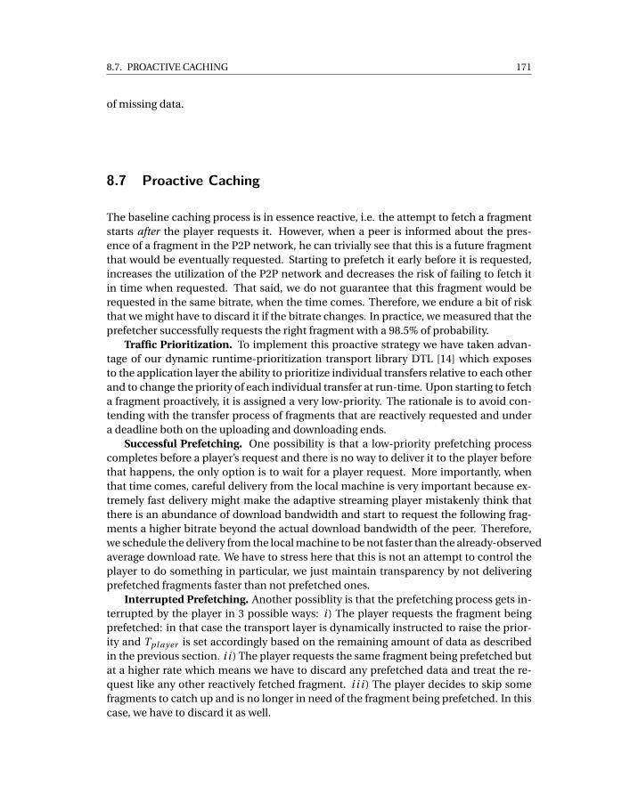
8.7. PROACTIVE CACHING 171
of missing data.
8.7 Proactive Caching
The baseline caching process is in essence reactive, i.e. the attempt to fetch a fragmentstarts after the player requests it. However, when a peer is informed about the pres-ence of a fragment in the P2P network, he can trivially see that this is a future fragmentthat would be eventually requested. Starting to prefetch it early before it is requested,increases the utilization of the P2P network and decreases the risk of failing to fetch itin time when requested. That said, we do not guarantee that this fragment would berequested in the same bitrate, when the time comes. Therefore, we endure a bit of riskthat we might have to discard it if the bitrate changes. In practice, we measured that theprefetcher successfully requests the right fragment with a 98.5% of probability.
Traffic Prioritization. To implement this proactive strategy we have taken advan-tage of our dynamic runtime-prioritization transport library DTL [14] which exposesto the application layer the ability to prioritize individual transfers relative to each otherand to change the priority of each individual transfer at run-time. Upon starting to fetcha fragment proactively, it is assigned a very low-priority. The rationale is to avoid con-tending with the transfer process of fragments that are reactively requested and undera deadline both on the uploading and downloading ends.
Successful Prefetching. One possibility is that a low-priority prefetching processcompletes before a player’s request and there is no way to deliver it to the player beforethat happens, the only option is to wait for a player request. More importantly, whenthat time comes, careful delivery from the local machine is very important because ex-tremely fast delivery might make the adaptive streaming player mistakenly think thatthere is an abundance of download bandwidth and start to request the following frag-ments a higher bitrate beyond the actual download bandwidth of the peer. Therefore,we schedule the delivery from the local machine to be not faster than the already-observedaverage download rate. We have to stress here that this is not an attempt to control theplayer to do something in particular, we just maintain transparency by not deliveringprefetched fragments faster than not prefetched ones.
Interrupted Prefetching. Another possiblity is that the prefetching process gets in-terrupted by the player in 3 possible ways: i ) The player requests the fragment beingprefetched: in that case the transport layer is dynamically instructed to raise the prior-ity and Tpl ayer is set accordingly based on the remaining amount of data as describedin the previous section. i i ) The player requests the same fragment being prefetched butat a higher rate which means we have to discard any prefetched data and treat the re-quest like any other reactively fetched fragment. i i i ) The player decides to skip somefragments to catch up and is no longer in need of the fragment being prefetched. In thiscase, we have to discard it as well.
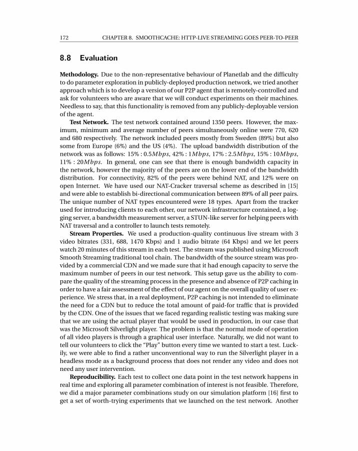
172 CHAPTER 8. SMOOTHCACHE: HTTP-LIVE STREAMING GOES PEER-TO-PEER
8.8 Evaluation
Methodology. Due to the non-representative behaviour of Planetlab and the difficultyto do parameter exploration in publicly-deployed production network, we tried anotherapproach which is to develop a version of our P2P agent that is remotely-controlled andask for volunteers who are aware that we will conduct experiments on their machines.Needless to say, that this functionality is removed from any publicly-deployable versionof the agent.
Test Network. The test network contained around 1350 peers. However, the max-imum, minimum and average number of peers simultaneously online were 770, 620and 680 respectively. The network included peers mostly from Sweden (89%) but alsosome from Europe (6%) and the US (4%). The upload bandwidth distribution of thenetwork was as follows: 15% : 0.5Mbps, 42% : 1Mbps, 17% : 2.5Mbps, 15% : 10Mbps,11% : 20Mbps. In general, one can see that there is enough bandwidth capacity inthe network, however the majority of the peers are on the lower end of the bandwidthdistribution. For connectivity, 82% of the peers were behind NAT, and 12% were onopen Internet. We have used our NAT-Cracker traversal scheme as described in [15]and were able to establish bi-directional communication between 89% of all peer pairs.The unique number of NAT types encountered were 18 types. Apart from the trackerused for introducing clients to each other, our network infrastructure contained, a log-ging server, a bandwidth measurement server, a STUN-like server for helping peers withNAT traversal and a controller to launch tests remotely.
Stream Properties. We used a production-quality continuous live stream with 3video bitrates (331, 688, 1470 Kbps) and 1 audio bitrate (64 Kbps) and we let peerswatch 20 minutes of this stream in each test. The stream was published using MicrosoftSmooth Streaming traditional tool chain. The bandwidth of the source stream was pro-vided by a commercial CDN and we made sure that it had enough capacity to serve themaximum number of peers in our test network. This setup gave us the ability to com-pare the quality of the streaming process in the presence and absence of P2P caching inorder to have a fair assessment of the effect of our agent on the overall quality of user ex-perience. We stress that, in a real deployment, P2P caching is not intended to eliminatethe need for a CDN but to reduce the total amount of paid-for traffic that is providedby the CDN. One of the issues that we faced regarding realistic testing was making surethat we are using the actual player that would be used in production, in our case thatwas the Microsoft Silverlight player. The problem is that the normal mode of operationof all video players is through a graphical user interface. Naturally, we did not want totell our volunteers to click the “Play” button every time we wanted to start a test. Luck-ily, we were able to find a rather unconventional way to run the Silverlight player in aheadless mode as a background process that does not render any video and does notneed any user intervention.
Reproducibility. Each test to collect one data point in the test network happens inreal time and exploring all parameter combination of interest is not feasible. Therefore,we did a major parameter combinations study on our simulation platform [16] first toget a set of worth-trying experiments that we launched on the test network. Another
8.8. EVALUATION 173
0
10
20
30
40
50
60
70
80
90
100
0 5 10 15 20
Savi
ngs
(%)
Time (minutes)
Improvements
NONEMT+PC
MT+PC+PMMT+PC+PM+US
MT+PC+PM+US+PR
Figure 8.3: Comparison of traffic savings with different algorithm improvements
problem is the fluctuation of network conditions and number of peers. We repeatedeach data point a number of times before gaining confidence that this is the averageperformance of a certain parameter combination.
Evaluation Metrics. The main metric that we use is traffic savings defined as thepercentage of the amount of data served from the P2P network from the total amountof data consumed by the peers. Every peer reports the amount of data served fromthe P2P network and streaming source every 30 seconds to the logging server. In ourbookkeeping, we keep track of how much of the traffic was due to fragments of a certainbitrate. The second important metric is buffering delay. The Silverlight player can beinstrumented to send debug information every time it goes in/out of buffering mode,i.e. whenever the player finds that the amount of internally-buffered data is not enoughfor playback, it sends a debug message to the server, which in our case is interceptedby the agent. Using this method, a peer can report the lengths of the periods it enteredinto buffering mode in the 30 seconds snapshots as well. At the end of the stream, wecalculate the sum of all the periods the player of a certain peer spent buffering.
8.8.1 Deployment Results
Step-by-Step Towards Savings. The first investigation we made was to start from thebaseline design with all the strategies set to the simplest possible. In fact, during thedevelopment cycle we used this baseline version repeatedly until we obtained a stableproduct with predictable and consistent savings level before we started to enable all theother improvements. Figure 8.3 shows the evolution of savings in time for all strategies.
174 CHAPTER 8. SMOOTHCACHE: HTTP-LIVE STREAMING GOES PEER-TO-PEER
0
20
40
60
80
100
x<5 5<x<10 10<x<30 30<x<60 x>60
Peer
s (%
)
Time (secs)
Improvements
NO P2PNONE
MT+PCMT+PC+PM
MT+PC+PM+USMT+PC+PM+US+PR
Figure 8.4: Comparison of cumulative buffering time for source only and improvements
The naive baseline caching was able to save a total of 44% of the source traffic. Afterthat, we worked on pushing the higher-bandwidth peers ahead and making each part-ner select peers that are useful using the request-point-aware partnership which movedthe savings to a level of 56%. So far, the partnership maintenance was random. Turn-ing on bit-rate-aware maintenance added only another 5% of savings but we believethat this is a key strategy that deserves more focus because it directly affects the effec-tive partnership size of other peers from each bitrate which directly affects savings. Forthe uploader selection, running the throughput-based picking achieved 68% of savings.Finally, we got our best savings by adding proactive caching which gave us 77% savings.
User Experience. Getting savings alone is not a good result unless we have provideda good user experience. To evaluate the user experience, we use two metrics: First, thepercentage of peers who experienced a total buffering time of less than 5 seconds, i.e.they enjoyed performance that did not really deviate much from live. Second, showingthat our P2P agent did not achieve this level of savings by forcing the adaptive streamingto move everyone to the lowest bitrate. For the first metric, Figure 8.4 shows that withall the improvements, we can make 87% of the network watch the stream with less than5 seconds of buffering delay. For the second metric, Figure 8.5(a) shows also that 88% ofall consumed traffic was on the highest bitrate and P2P alone shouldering 75% (Figure8.5(b)), an indication that, for the most part, peers have seen the video at the highestbitrate with a major contribution from the P2P network.
P2P-less as a Reference. We take one more step beyond showing that the system of-fers substantial savings with reasonable user experience, namely to understand whatwould be the user experience in case all the peers streamed directly from the CDN.
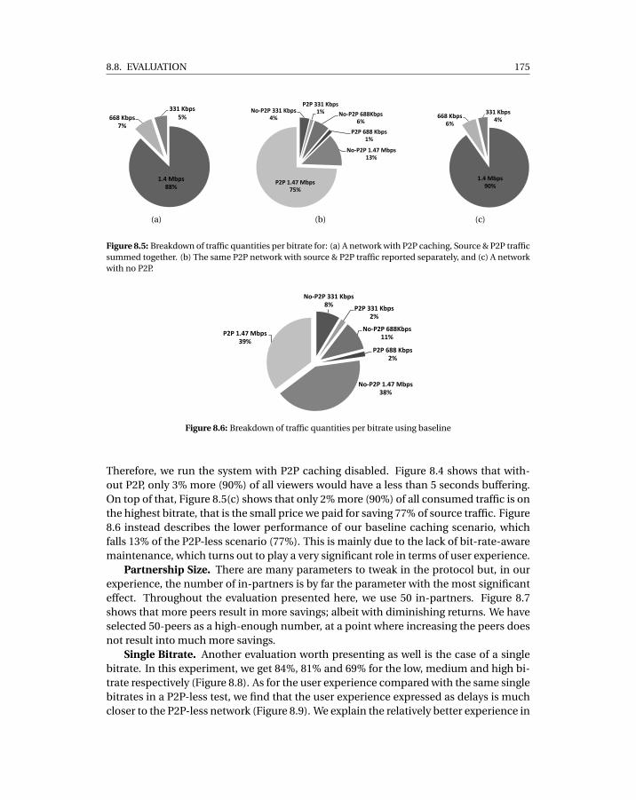
8.8. EVALUATION 175
1.4$Mbps$88%$
668$Kbps$7%$
$$331$Kbps$
5%$
(a)
No#P2P&331&Kbps&4%&
P2P&331&Kbps&1%& No#P2P&688Kbps&
6%&
P2P&688&Kbps&1%&
No#P2P&1.47&Mbps&13%&
P2P&1.47&Mbps&75%&
(b)
1.4$Mbps$90%$
668$Kbps$6%$
331$Kbps$4%$
(c)
Figure 8.5: Breakdown of traffic quantities per bitrate for: (a) A network with P2P caching, Source & P2P trafficsummed together. (b) The same P2P network with source & P2P traffic reported separately, and (c) A networkwith no P2P.
No#P2P&331&Kbps&8%& P2P&331&Kbps&
2%&
No#P2P&688Kbps&11%&
P2P&688&Kbps&2%&
No#P2P&1.47&Mbps&38%&
P2P&1.47&Mbps&39%&
Figure 8.6: Breakdown of traffic quantities per bitrate using baseline
Therefore, we run the system with P2P caching disabled. Figure 8.4 shows that with-out P2P, only 3% more (90%) of all viewers would have a less than 5 seconds buffering.On top of that, Figure 8.5(c) shows that only 2% more (90%) of all consumed traffic is onthe highest bitrate, that is the small price we paid for saving 77% of source traffic. Figure8.6 instead describes the lower performance of our baseline caching scenario, whichfalls 13% of the P2P-less scenario (77%). This is mainly due to the lack of bit-rate-awaremaintenance, which turns out to play a very significant role in terms of user experience.
Partnership Size. There are many parameters to tweak in the protocol but, in ourexperience, the number of in-partners is by far the parameter with the most significanteffect. Throughout the evaluation presented here, we use 50 in-partners. Figure 8.7shows that more peers result in more savings; albeit with diminishing returns. We haveselected 50-peers as a high-enough number, at a point where increasing the peers doesnot result into much more savings.
Single Bitrate. Another evaluation worth presenting as well is the case of a singlebitrate. In this experiment, we get 84%, 81% and 69% for the low, medium and high bi-trate respectively (Figure 8.8). As for the user experience compared with the same singlebitrates in a P2P-less test, we find that the user experience expressed as delays is muchcloser to the P2P-less network (Figure 8.9). We explain the relatively better experience in
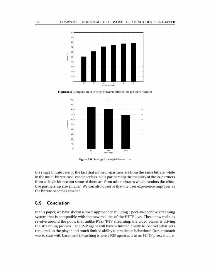
176 CHAPTER 8. SMOOTHCACHE: HTTP-LIVE STREAMING GOES PEER-TO-PEER
0
10
20
30
40
50
60
70
80
90
100
10 20 30 40 50 60
Savi
ngs
(%)
Number of Partners
Figure 8.7: Comparison of savings between different in-partners number
0
10
20
30
40
50
60
70
80
90
100
331 668 1470
Savi
ngs
(%)
Bitrate (Kbps)
Figure 8.8: Savings for single bitrate runs
the single bitrate case by the fact that all the in-partners are from the same bitrate, whilein the multi-bitrate case, each peer has in his partnership the majority of the in-partnersfrom a single bitrate but some of them are from other bitrates which renders the effec-tive partnership size smaller. We can also observe that the user experience improves asthe bitrate becomes smaller.
8.9 Conclusion
In this paper, we have shown a novel approach in building a peer-to-peer live streamingsystem that is compatible with the new realities of the HTTP-live. These new realitiesrevolve around the point that unlike RTSP/RTP streaming, the video player is drivingthe streaming process. The P2P agent will have a limited ability to control what getsrendered on the player and much limited ability to predict its behaviour. Our approachwas to start with baseline P2P caching where a P2P agent acts as an HTTP proxy that re-
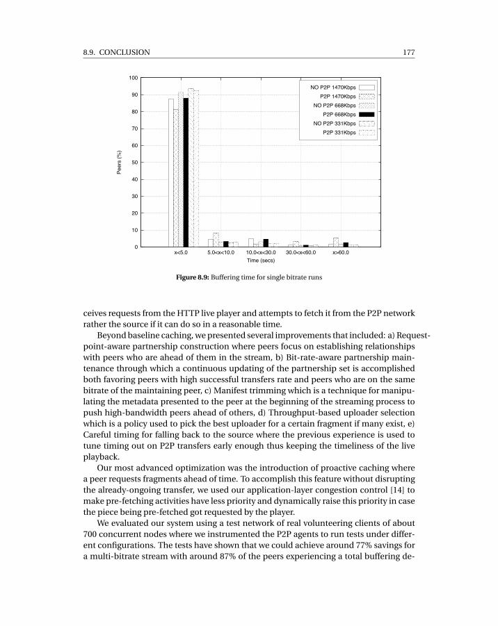
8.9. CONCLUSION 177
0
10
20
30
40
50
60
70
80
90
100
x<5.0 5.0<x<10.0 10.0<x<30.0 30.0<x<60.0 x>60.0
Peer
s (%
)
Time (secs)
NO P2P 1470KbpsP2P 1470Kbps
NO P2P 668KbpsP2P 668Kbps
NO P2P 331KbpsP2P 331Kbps
Figure 8.9: Buffering time for single bitrate runs
ceives requests from the HTTP live player and attempts to fetch it from the P2P networkrather the source if it can do so in a reasonable time.
Beyond baseline caching, we presented several improvements that included: a) Request-point-aware partnership construction where peers focus on establishing relationshipswith peers who are ahead of them in the stream, b) Bit-rate-aware partnership main-tenance through which a continuous updating of the partnership set is accomplishedboth favoring peers with high successful transfers rate and peers who are on the samebitrate of the maintaining peer, c) Manifest trimming which is a technique for manipu-lating the metadata presented to the peer at the beginning of the streaming process topush high-bandwidth peers ahead of others, d) Throughput-based uploader selectionwhich is a policy used to pick the best uploader for a certain fragment if many exist, e)Careful timing for falling back to the source where the previous experience is used totune timing out on P2P transfers early enough thus keeping the timeliness of the liveplayback.
Our most advanced optimization was the introduction of proactive caching wherea peer requests fragments ahead of time. To accomplish this feature without disruptingthe already-ongoing transfer, we used our application-layer congestion control [14] tomake pre-fetching activities have less priority and dynamically raise this priority in casethe piece being pre-fetched got requested by the player.
We evaluated our system using a test network of real volunteering clients of about700 concurrent nodes where we instrumented the P2P agents to run tests under differ-ent configurations. The tests have shown that we could achieve around 77% savings fora multi-bitrate stream with around 87% of the peers experiencing a total buffering de-
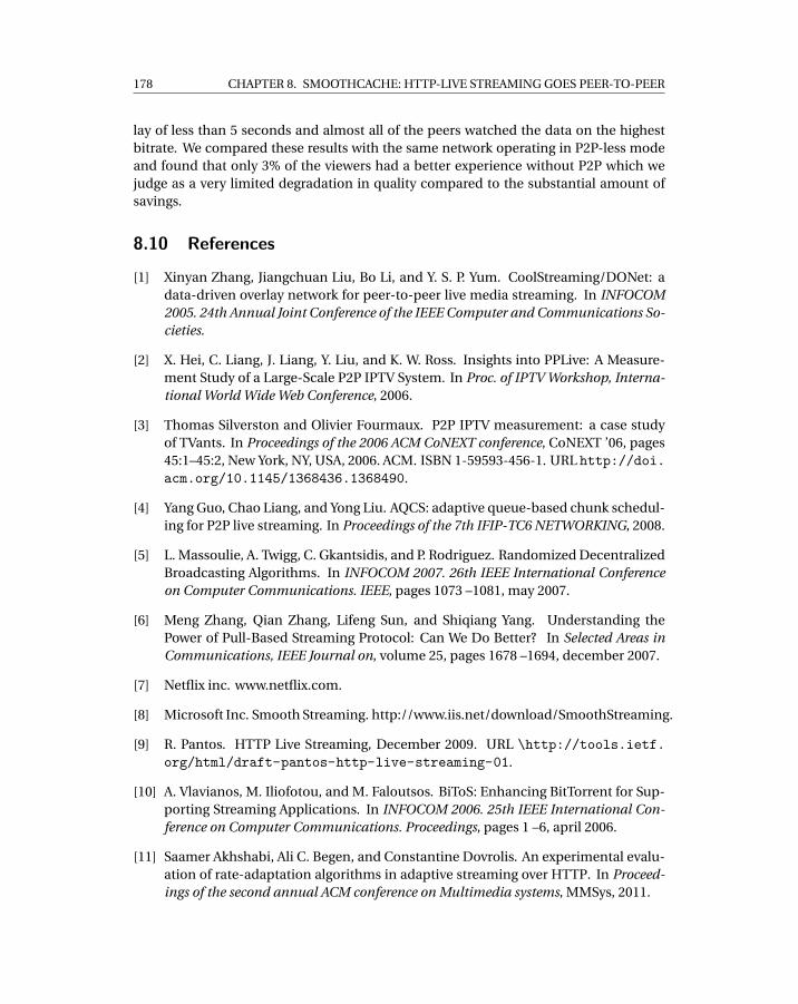
178 CHAPTER 8. SMOOTHCACHE: HTTP-LIVE STREAMING GOES PEER-TO-PEER
lay of less than 5 seconds and almost all of the peers watched the data on the highestbitrate. We compared these results with the same network operating in P2P-less modeand found that only 3% of the viewers had a better experience without P2P which wejudge as a very limited degradation in quality compared to the substantial amount ofsavings.
8.10 References
[1] Xinyan Zhang, Jiangchuan Liu, Bo Li, and Y. S. P. Yum. CoolStreaming/DONet: adata-driven overlay network for peer-to-peer live media streaming. In INFOCOM2005. 24th Annual Joint Conference of the IEEE Computer and Communications So-cieties.
[2] X. Hei, C. Liang, J. Liang, Y. Liu, and K. W. Ross. Insights into PPLive: A Measure-ment Study of a Large-Scale P2P IPTV System. In Proc. of IPTV Workshop, Interna-tional World Wide Web Conference, 2006.
[3] Thomas Silverston and Olivier Fourmaux. P2P IPTV measurement: a case studyof TVants. In Proceedings of the 2006 ACM CoNEXT conference, CoNEXT ’06, pages45:1–45:2, New York, NY, USA, 2006. ACM. ISBN 1-59593-456-1. URL http://doi.acm.org/10.1145/1368436.1368490.
[4] Yang Guo, Chao Liang, and Yong Liu. AQCS: adaptive queue-based chunk schedul-ing for P2P live streaming. In Proceedings of the 7th IFIP-TC6 NETWORKING, 2008.
[5] L. Massoulie, A. Twigg, C. Gkantsidis, and P. Rodriguez. Randomized DecentralizedBroadcasting Algorithms. In INFOCOM 2007. 26th IEEE International Conferenceon Computer Communications. IEEE, pages 1073 –1081, may 2007.
[6] Meng Zhang, Qian Zhang, Lifeng Sun, and Shiqiang Yang. Understanding thePower of Pull-Based Streaming Protocol: Can We Do Better? In Selected Areas inCommunications, IEEE Journal on, volume 25, pages 1678 –1694, december 2007.
[7] Netflix inc. www.netflix.com.
[8] Microsoft Inc. Smooth Streaming. http://www.iis.net/download/SmoothStreaming.
[9] R. Pantos. HTTP Live Streaming, December 2009. URL \http://tools.ietf.org/html/draft-pantos-http-live-streaming-01.
[10] A. Vlavianos, M. Iliofotou, and M. Faloutsos. BiToS: Enhancing BitTorrent for Sup-porting Streaming Applications. In INFOCOM 2006. 25th IEEE International Con-ference on Computer Communications. Proceedings, pages 1 –6, april 2006.
[11] Saamer Akhshabi, Ali C. Begen, and Constantine Dovrolis. An experimental evalu-ation of rate-adaptation algorithms in adaptive streaming over HTTP. In Proceed-ings of the second annual ACM conference on Multimedia systems, MMSys, 2011.
8.10. REFERENCES 179
[12] Chenghao Liu, Imed Bouazizi, and Moncef Gabbouj. Parallel Adaptive HTTP MediaStreaming. In Computer Communications and Networks (ICCCN), Proc. of 20thInternational Conference on, pages 1 –6, 31 2011-aug. 4 2011.
[13] Hao Yin, Xuening Liu, Tongyu Zhan, Vyas Sekar, Feng Qiu, Chuang Lin, Hui Zhang,and Bo Li. Livesky: Enhancing cdn with p2p. ACM Trans. Multimedia Comput.Commun. Appl., 6:16:1–16:19, August 2010. ISSN 1551-6857. URL http://doi.acm.org/10.1145/1823746.1823750.
[14] Riccardo Reale, Roberto Roverso, Sameh El-Ansary, and Seif Haridi. DTL: DynamicTransport Library for Peer-To-Peer Applications. In In Proc. of the 12th Interna-tional Conference on Distributed Computing and Networking, ICDCN, Jan 2012.
[15] Roberto Roverso, Sameh El-Ansary, and Seif Haridi. NATCracker: NAT Combina-tions Matter. In Proc. of 18th International Conference on Computer Communica-tions and Networks, ICCCN ’09, SF, CA, USA, 2009. IEEE Computer Society. ISBN978-1-4244-4581-3.
[16] Roberto Roverso, Sameh El-Ansary, Alexandros Gkogkas, and Seif Haridi. Mesmer-izer: A effective tool for a complete peer-to-peer software development life-cycle.In In Proceedings of SIMUTOOLS, March 2011.

CH
AP
TE
R
9SMOOTHCACHE 2.0: CDN-QUALITY
ADAPTIVE HTTP LIVE STREAMING ON
P2P OVERLAYS

9.1. INTRODUCTION 183
SmoothCache 2.0: the HTTP-Live peer-to-peerCDN1
Roberto Roverso1,2, Riccardo Reale1, Sameh El-Ansary1 and Seif Haridi2
1Peerialism ABStockholm, Sweden
[roberto,riccardo,sameh]@peerialism.com
2KTH - Royal Institute of TechnologyStockholm, Sweden[haridi]@kth.se
Abstract
In recent years, adaptive HTTP streaming protocols have become the de-factostandard in the industry for the distribution of live and video-on-demand contentover the Internet. This paper presents SmoothCache 2.0, a distributed cache foradaptive HTTP live streaming content based on peer-to-peer (P2P) overlays. Thecontribution of this work is twofold. From a systems perspective, to the best ofour knowledge, it is the only commercially deployed P2P platform which supportsrecent live streaming protocols based on HTTP as a transport and the concept ofadaptive bitrate switching. From an algorithmic perspective, the system describesa novel set of overlay construction and prefetching techniques that realize: i ) sub-stantial savings in terms of the bandwidth load on the source of the stream, and i i )CDN-quality user experience in terms of delay from the live playing point and themostly-watched bitrate. In order to support our claims, we conduct a methodicalevaluation encompassing a subset of thousands of real customers’ machines whichwho agreed to install an instrumented version of our software.
9.1 Introduction
Peer-to-Peer live streaming (PLS) is the problem of improving distribution efficiencyfor a given online live broadcast by letting viewers of the content contribute with theirresources, namely bandwidth.
1Submitted to a conference and currently under review.
184
CHAPTER 9. SMOOTHCACHE 2.0: CDN-QUALITY ADAPTIVE HTTP LIVE STREAMING ON P2P
OVERLAYS
Previous work in this area has produced a lot of systems such as PPlive [1], Cool-Streaming [2], T-bone [3], and more recently Bittorrent live[4]. Overlay constructionfor such applications falls mainly into 2 classes, tree-based and mesh-based systems.Although a consensus has not been reached on the best approach, mesh-based ap-proaches lately became more popular as they are more robust to churn [5, 6], whiletree-based overlays are more cumbersome to maintain in the same conditions [7].
Despite the increased maturity in the field, an important aspect which we find rel-atively under-studied is the ramification of the recent trend of using HTTP-live stream-ing instead of the traditional RTSP/RTP protocol for broadcast of live video content overthe Internet. HTTP-live streaming consists of a set of protocols which all utilize theHTTP protocol as transport [8]. HTTP-live streaming changes the way the producer ofthe content (usually a CDN) and the consumer of the content (the media player) inter-act. Traditional streaming protocols such as the RTSP/RTP are based on a push-basedmodel, where the player requests a certain stream and then the server pushes contentover UDP to the player controlling the speed of the delivery. HTTP-live streaming pro-tocols are instead based on a pull-model, where it is the player which requests contentchunks over HTTP at the pace it deems suitable. On top of that, the HTTP-live proto-cols have been designed to support adaptive bitrate mode of operation, which avails thestream in a number of qualities. The choice of which quality to retrieve/reproduce is leftto the player.
All major actors in the online broadcasting business, such as Microsoft, Adobe andApple, have developed technologies which embrace HTTP-streaming and the conceptof adaptive bitrate switching as the main approach for broadcasting. HTTP live has beenadopted by content services and creators like Netflix, Hulu and the BBC with supportacross all platforms and OSs, including computers, tablets and smart phones.
The shift from the push-based RTSP/RTP protocol to the pull-based HTTP-live pro-tocols has rendered many of the classical assumptions made in the current state-of-the-art PLS literature obsolete [9]. For all practical purposes, any new PLS algorithm, irre-spective of its theoretical soundness, won’t be deployable if it does not take into accountthe realities of the mainstream broadcasting ecosystem around it.
Being an industrial entity, our attention to this area grew as we started to find itdifficult to raise any reasonable market interest while overlooking the fact that both theCDNs and the live streaming solution vendors are focusing on HTTP-based solutions.Our first take on the problem of designing a distributed caching system tailored to HTTPlive streaming [9] showed that it is possible to achieve significant savings towards thesource of the stream by using peer-to-peer overlays.
In this iteration, we aim higher by not only targeting high savings but also makingsure viewers experience CDN-like QoE in terms of delay from the live point. In orderto achieve our goal, we exploit detailed knowledge of the HTTP live streaming distri-bution chain. Based on that, we build a distributed caching solution which prefetchescontent ahead of the live deadline and distributes it to all nodes in the network such asto significantly decrease the bandwidth requirements on the source of the stream.
The distribution of data happens over a self-organizing overlay network that takesinto account many factors such as upload bandwidth capacity, connectivity constraints,
9.2. RELATED WORK 185
performance history, prefetching point and currently watched bitrate all of which worktogether to maximize flow of fragments in the network. In the description of our system,we focus primarily on how our prefetching techniques work and on the overlay con-struction heuristics. On top of that, we conduct a thorough evaluation of our overlaytechniques on a real network of thousands of consumer machines and show how eachof our techniques individually contributes to the performance. We also show empiri-cally that the resulting system provides the same QoE of a standard CDN, with respectto cumulative buffering time and mostly watched bitrate.
9.2 Related Work
First, an important high-level distinguishing feature of SmoothCache from classical peer-to-peer solutions is that, in all other systems, bounded source bandwidth is assumedand the challenge is to maximize throughput, but nothing prevents the maximum de-lay from the live point to grow with the network size [10]. Our industrial experiencehas led us to believe that commercial content owners are not willing to compromiseon quality of user experience. In contrast, we have designed this system to achieve abounded delay that is no worse than a CDN. That is, we have first to meet the same tar-gets of throughput and playback delay of a CDN, and then try to maximize savings. Thisconcept is found both in peer-assisted and cloud-assisted systems. The former categoryincludes systems which build their own ad-hoc infrastructure to aid the peer-to-peeroverlay, while the latter category use existing infrastructure such as Content DeliveryNetworks for the same purpose. While the approaches may differ, both categories ofsystems share the same goal of enforcing a specific target quality of user experience forviewers by using the least amount of infrastructure resources.
Cloud-assisted systems, such as LiveSky [11] and CALMS [12], utilize cloud-baseddynamically allocated resources to support the peer-to-peer delivery. The main draw-back of cloud-assisted solutions is that they are cumbersome to deploy in existing livestreaming systems that are already relying on CDN services. They in fact require a com-plete re-engineering of the server-side of the system to allow bidirectional feedbackfrom the peer-to-peer overlay and a centralized coordinator which controls the cloudresources. On top of that, in cloud-assisted systems a completely new managementlayer must be deployed for the coordinator to enforce its cloud allocation decisions.
SmoothCache 2.0 belongs instead to the peer-assisted category, which leveragesthe inherent ability of CDN networks to dynamically scale up and down resources andtherefore cope with variable load from the peer-to-peer overlay. Dynamic scalabilityis one of the main features of CDNs because in such systems it is very common to ex-perience dramatically varying demand for video content depending on factors such asincreased/decreased popularity and time of the day.
The peer-assisted approach has been applied mostly to video on demand (VoD)streaming rather than live streaming. In the industry, we find instances of peer-assistedVoD systems in Akamai’s NetSession [13] and Adobe’s Flash framework [14][15].
In academia instead, efforts have been directed at understanding in general, and
186
CHAPTER 9. SMOOTHCACHE 2.0: CDN-QUALITY ADAPTIVE HTTP LIVE STREAMING ON P2P
OVERLAYS
without considering the details of streaming protocols, what are the best prefetch poli-cies for peers to download VoD content ahead of playback such that the load on thesource of the stream is minimized [16][17]. Recent work instead proposed a practicalsolution to enable peer-assisted distribution of VoD content with adaptive bitrate HTTPstreaming protocols using plugin-less browser-based technologies with Maygh [18]. Au-thors show that Maygh can save up to 75% of the load on the CDN in the consideredscenarios.
We believe, given the presented approaches, that SmoothCache 2.0 is the first peer-assisted live streaming system to be designed with HTTP adaptive streaming in mind.Other systems have addressed the problem of adaptive streaming in the past by usingLayered Video Coding (LC) [19] or Multiple Descriptor Coding (MDC) [20]. There aredifferent LC and MDC techniques in the literature, all of which come at the expense ofvarying levels of added overhead, in terms of redundancy, computational complexityand reconstruction performance. To the best of our knowledge, there is no wide adop-tion of either technique in mainstream streaming platforms. On top of that, in Smooth-Cache 2.0 we show that HTTP adaptive streaming is achievable without data codingtechniques and therefore without incurring the associated overhead.
Regarding live P2P streaming in general, Peerstreamer[21] is one of the actively-maintained mesh-based systems. However, it is not integrated with existing commer-cial live streaming protocols such as [22, 23, 24], and it does not support adaptive bitratestreaming.
In order to guide our design, we also investigated theoretical work which builds onthe peer-assisted paradigm. Liu et Al. [25] assert the benefits of peer-assisted delivery forsingle bitrate streams by providing a theoretical framework which highlights the trade-offs between three fundamental metrics: savings towards the source of the stream, bi-trate watched by peers and number of hops from the source of the stream. The model ishowever applicable only to tree-based overlay networks deployed on always-on set-top-boxes and therefore absent of churn. Mansy et al. [26] describe a model for designingand operating a peer-assisted system. Specifically, the model estimates the minimumamount of peers which should be served by the CDN and also which bitrate shouldpeers download given the CDN and peers bandwidth capacity. The significant limita-tion of this work is that it does not model bitrate switching at the player side, which is afundamental characteristic of adaptive HTTP streaming protocols. In the model, peersare not allowed to switch bitrate according to the observed throughput but rather it isthe CDN which controls which bitrate they are watching. We are not aware of any othertheoretical work which considers both the peer-assisted paradigm and adaptive HTTPstreaming principles.
9.3 System Architecture
SmoothCache 2.0 is composed of a client (the PLS agent) which is installed on the viewer’smachines, and by a number of helper services which represent our operational central-ized infrastructure. It is important to note that our system is designed to be transparent
9.3. SYSTEM ARCHITECTURE 187
to already-existing streaming infrastructure in order to ensure both vendor neutrality aswell as simplified deployment. Therefore, we do not operate our own stream origin. Weassume that there is an already-published stream, for instance from a Content Distri-bution Network (CDN), that can be played directly from its source and our customerswould transparently use our system to minimize the load on that source. That said, wesolve the problem of reducing the load on the source of the stream the same way a CDNwould: by building a caching scheme.
9.3.1 Baseline cachingThe basic idea of our system is to build a random graph between all nodes watchinga stream. Upon a content fragment request from the player running on the peer, thePLS agent tries to timely retrieve the data requested from other peers in the overlay. Ifa fragment cannot be retrieved from any other peer on time, the agent downloads themissing portion of the fragment from the source of the stream, i.e. the CDN. By fallingback to the source, we guarantee that all fragments are delivered on time even if theoverlay network cannot retrieve such fragments, thereby guaranteeing the desired levelof QoE.
9.3.2 PLS AgentIn the absence of our PLS agent, the HTTP live streaming process starts from the videoencoder which outputs video “fragments” of constant duration δ as they are “born”in real time. Each fragment is created in multiple qualities (bitrates) simultaneously.Therefore, a fragment is uniquely identified by a timestamp and a bitrate.The fragmentsare published on a standard web-server. In addition to that, a constantly-changing man-ifest file is updated to contain the newly-born fragment.
To start playing a stream, a player makes an HTTP request to fetch the manifest,learns what is the latest fragment, then makes a second request to access the fragmentwith the highest timestamp (the most recent) in the manifest and continues retrieving apiece every δ seconds. Since the stream is usually CDN hosted, therefore, based on thethroughput of the CDN, the player jumps to a higher bitrate or a lower bitrate startinginitially from the lowest. The bitrate switches are performed to make sure the player isnot drifting from the live playing point.
In the presence of our PLS agent, all player requests, are redirected to the local PLSagent instead of going directly to the source of the stream and that is the only changethat needs to occur compared to normal operation without our agent.
Internally, as illustrated in Figure 9.1, the PLS agent has an HTTP server which re-ceives sequential HTTP requests, detects which protocol they are made for, that beingApple’s HTTP Live Streaming (HLS)[22], Adobe’s HDS[23] or Microsoft’s Smooth Stream-ing (SS)[24], and forwards them to a protocol-specific component which extracts rel-evant information and generates protocol-neutral requests to the Distributed Cachecomponent. The latter decides whether a request can be served from the source orfrom the P2P network using a Fragment Index, that keeps track of fragments available
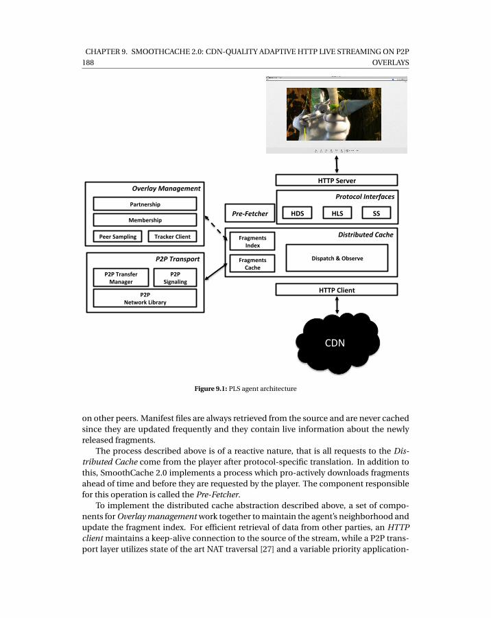
188
CHAPTER 9. SMOOTHCACHE 2.0: CDN-QUALITY ADAPTIVE HTTP LIVE STREAMING ON P2P
OVERLAYS
HTTP$Server$
Protocol'Interfaces'
HDS$ HLS$ SS$
Distributed'Cache'
Pre5Fetcher''
Fragments$Cache$
Dispatch$&$Observe$P2P'Transport'
P2P$Network$Library$
P2P$Transfer$Manager$
Overlay'Management'
Peer$Sampling$
Partnership$
Membership$
Tracker$Client$
CDN"
Fragments$Index$
HTTP$Client$
P2P$Signaling$
Figure 9.1: PLS agent architecture
on other peers. Manifest files are always retrieved from the source and are never cachedsince they are updated frequently and they contain live information about the newlyreleased fragments.
The process described above is of a reactive nature, that is all requests to the Dis-tributed Cache come from the player after protocol-specific translation. In addition tothis, SmoothCache 2.0 implements a process which pro-actively downloads fragmentsahead of time and before they are requested by the player. The component responsiblefor this operation is called the Pre-Fetcher.
To implement the distributed cache abstraction described above, a set of compo-nents for Overlay management work together to maintain the agent’s neighborhood andupdate the fragment index. For efficient retrieval of data from other parties, an HTTPclient maintains a keep-alive connection to the source of the stream, while a P2P trans-port layer utilizes state of the art NAT traversal [27] and a variable priority application-
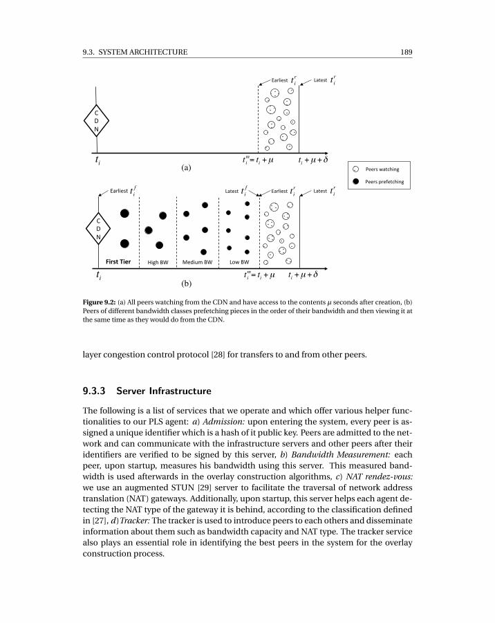
9.3. SYSTEM ARCHITECTURE 189
ti tmi = ti +µ ti +µ +δ
CDN"
="
First&Tier& High"BW" Medium"BW" Low"BW"
ti tmi = ti +µ ti +µ +δ
t ri
CDN"
(a)!
(b)!
t fiLatest"t fiEarliest" Earliest" Latest" t ri
t riEarliest" Latest" t ri
Peers"watching"
Peers"prefetching"
Figure 9.2: (a) All peers watching from the CDN and have access to the contents µ seconds after creation, (b)Peers of different bandwidth classes prefetching pieces in the order of their bandwidth and then viewing it atthe same time as they would do from the CDN.
layer congestion control protocol [28] for transfers to and from other peers.
9.3.3 Server Infrastructure
The following is a list of services that we operate and which offer various helper func-tionalities to our PLS agent: a) Admission: upon entering the system, every peer is as-signed a unique identifier which is a hash of it public key. Peers are admitted to the net-work and can communicate with the infrastructure servers and other peers after theiridentifiers are verified to be signed by this server, b) Bandwidth Measurement: eachpeer, upon startup, measures his bandwidth using this server. This measured band-width is used afterwards in the overlay construction algorithms, c) NAT rendez-vous:we use an augmented STUN [29] server to facilitate the traversal of network addresstranslation (NAT) gateways. Additionally, upon startup, this server helps each agent de-tecting the NAT type of the gateway it is behind, according to the classification definedin [27], d)Tracker: The tracker is used to introduce peers to each others and disseminateinformation about them such as bandwidth capacity and NAT type. The tracker servicealso plays an essential role in identifying the best peers in the system for the overlayconstruction process.
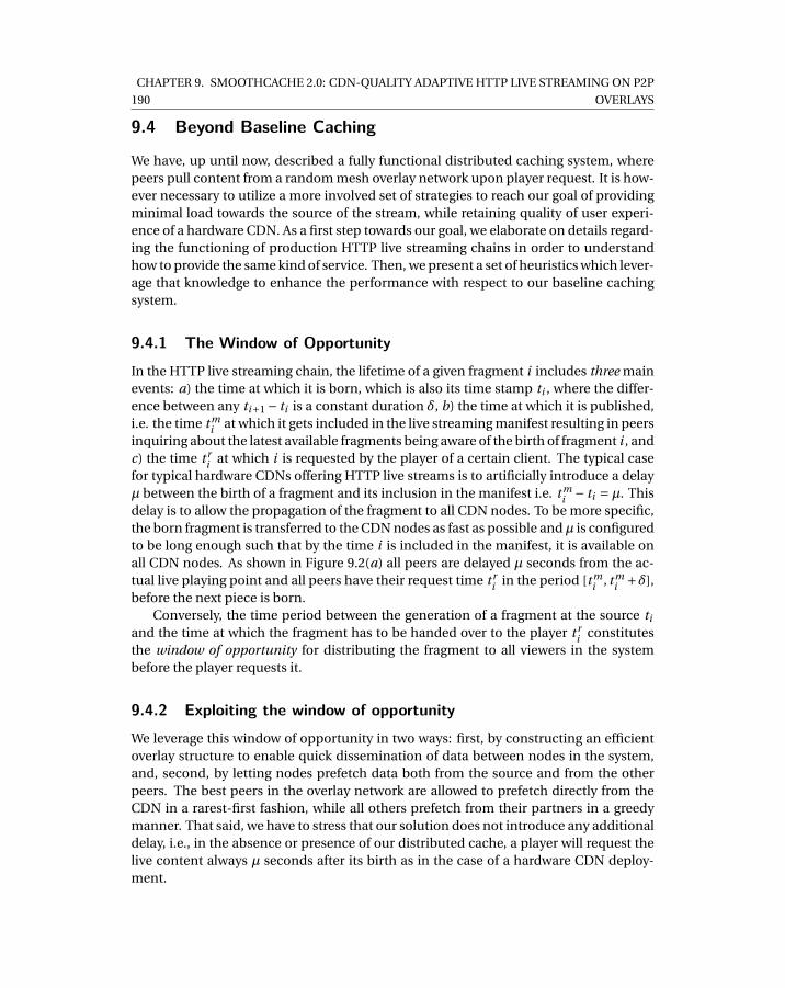
190
CHAPTER 9. SMOOTHCACHE 2.0: CDN-QUALITY ADAPTIVE HTTP LIVE STREAMING ON P2P
OVERLAYS
9.4 Beyond Baseline Caching
We have, up until now, described a fully functional distributed caching system, wherepeers pull content from a random mesh overlay network upon player request. It is how-ever necessary to utilize a more involved set of strategies to reach our goal of providingminimal load towards the source of the stream, while retaining quality of user experi-ence of a hardware CDN. As a first step towards our goal, we elaborate on details regard-ing the functioning of production HTTP live streaming chains in order to understandhow to provide the same kind of service. Then, we present a set of heuristics which lever-age that knowledge to enhance the performance with respect to our baseline cachingsystem.
9.4.1 The Window of OpportunityIn the HTTP live streaming chain, the lifetime of a given fragment i includes three mainevents: a) the time at which it is born, which is also its time stamp ti , where the differ-ence between any ti+1 − ti is a constant duration δ, b) the time at which it is published,i.e. the time t m
i at which it gets included in the live streaming manifest resulting in peersinquiring about the latest available fragments being aware of the birth of fragment i , andc) the time t r
i at which i is requested by the player of a certain client. The typical casefor typical hardware CDNs offering HTTP live streams is to artificially introduce a delayµ between the birth of a fragment and its inclusion in the manifest i.e. t m
i − ti = µ. Thisdelay is to allow the propagation of the fragment to all CDN nodes. To be more specific,the born fragment is transferred to the CDN nodes as fast as possible andµ is configuredto be long enough such that by the time i is included in the manifest, it is available onall CDN nodes. As shown in Figure 9.2(a) all peers are delayed µ seconds from the ac-tual live playing point and all peers have their request time t r
i in the period [t mi , t m
i +δ],before the next piece is born.
Conversely, the time period between the generation of a fragment at the source ti
and the time at which the fragment has to be handed over to the player t ri constitutes
the window of opportunity for distributing the fragment to all viewers in the systembefore the player requests it.
9.4.2 Exploiting the window of opportunityWe leverage this window of opportunity in two ways: first, by constructing an efficientoverlay structure to enable quick dissemination of data between nodes in the system,and, second, by letting nodes prefetch data both from the source and from the otherpeers. The best peers in the overlay network are allowed to prefetch directly from theCDN in a rarest-first fashion, while all others prefetch from their partners in a greedymanner. That said, we have to stress that our solution does not introduce any additionaldelay, i.e., in the absence or presence of our distributed cache, a player will request thelive content always µ seconds after its birth as in the case of a hardware CDN deploy-ment.
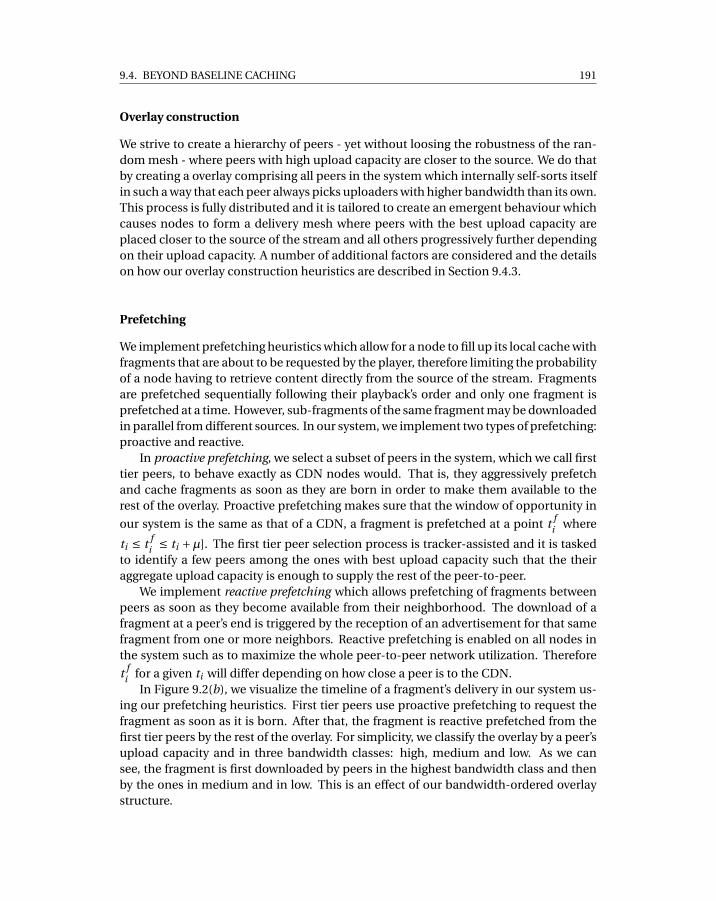
9.4. BEYOND BASELINE CACHING 191
Overlay construction
We strive to create a hierarchy of peers - yet without loosing the robustness of the ran-dom mesh - where peers with high upload capacity are closer to the source. We do thatby creating a overlay comprising all peers in the system which internally self-sorts itselfin such a way that each peer always picks uploaders with higher bandwidth than its own.This process is fully distributed and it is tailored to create an emergent behaviour whichcauses nodes to form a delivery mesh where peers with the best upload capacity areplaced closer to the source of the stream and all others progressively further dependingon their upload capacity. A number of additional factors are considered and the detailson how our overlay construction heuristics are described in Section 9.4.3.
Prefetching
We implement prefetching heuristics which allow for a node to fill up its local cache withfragments that are about to be requested by the player, therefore limiting the probabilityof a node having to retrieve content directly from the source of the stream. Fragmentsare prefetched sequentially following their playback’s order and only one fragment isprefetched at a time. However, sub-fragments of the same fragment may be downloadedin parallel from different sources. In our system, we implement two types of prefetching:proactive and reactive.
In proactive prefetching, we select a subset of peers in the system, which we call firsttier peers, to behave exactly as CDN nodes would. That is, they aggressively prefetchand cache fragments as soon as they are born in order to make them available to therest of the overlay. Proactive prefetching makes sure that the window of opportunity in
our system is the same as that of a CDN, a fragment is prefetched at a point t fi where
ti ≤ t fi ≤ ti +µ]. The first tier peer selection process is tracker-assisted and it is tasked
to identify a few peers among the ones with best upload capacity such that the theiraggregate upload capacity is enough to supply the rest of the peer-to-peer.
We implement reactive prefetching which allows prefetching of fragments betweenpeers as soon as they become available from their neighborhood. The download of afragment at a peer’s end is triggered by the reception of an advertisement for that samefragment from one or more neighbors. Reactive prefetching is enabled on all nodes inthe system such as to maximize the whole peer-to-peer network utilization. Therefore
t fi for a given ti will differ depending on how close a peer is to the CDN.
In Figure 9.2(b), we visualize the timeline of a fragment’s delivery in our system us-ing our prefetching heuristics. First tier peers use proactive prefetching to request thefragment as soon as it is born. After that, the fragment is reactive prefetched from thefirst tier peers by the rest of the overlay. For simplicity, we classify the overlay by a peer’supload capacity and in three bandwidth classes: high, medium and low. As we cansee, the fragment is first downloaded by peers in the highest bandwidth class and thenby the ones in medium and in low. This is an effect of our bandwidth-ordered overlaystructure.
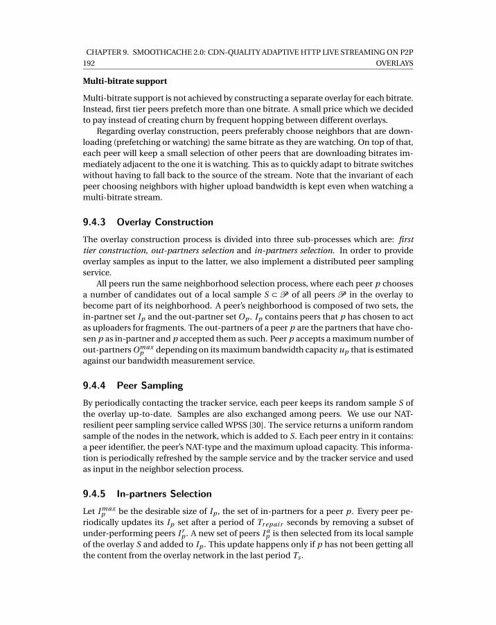
192
CHAPTER 9. SMOOTHCACHE 2.0: CDN-QUALITY ADAPTIVE HTTP LIVE STREAMING ON P2P
OVERLAYS
Multi-bitrate support
Multi-bitrate support is not achieved by constructing a separate overlay for each bitrate.Instead, first tier peers prefetch more than one bitrate. A small price which we decidedto pay instead of creating churn by frequent hopping between different overlays.
Regarding overlay construction, peers preferably choose neighbors that are down-loading (prefetching or watching) the same bitrate as they are watching. On top of that,each peer will keep a small selection of other peers that are downloading bitrates im-mediately adjacent to the one it is watching. This as to quickly adapt to bitrate switcheswithout having to fall back to the source of the stream. Note that the invariant of eachpeer choosing neighbors with higher upload bandwidth is kept even when watching amulti-bitrate stream.
9.4.3 Overlay ConstructionThe overlay construction process is divided into three sub-processes which are: firsttier construction, out-partners selection and in-partners selection. In order to provideoverlay samples as input to the latter, we also implement a distributed peer samplingservice.
All peers run the same neighborhood selection process, where each peer p choosesa number of candidates out of a local sample S ⊂ P of all peers P in the overlay tobecome part of its neighborhood. A peer’s neighborhood is composed of two sets, thein-partner set Ip and the out-partner set Op . Ip contains peers that p has chosen to actas uploaders for fragments. The out-partners of a peer p are the partners that have cho-sen p as in-partner and p accepted them as such. Peer p accepts a maximum number ofout-partners Omax
p depending on its maximum bandwidth capacity up that is estimatedagainst our bandwidth measurement service.
9.4.4 Peer SamplingBy periodically contacting the tracker service, each peer keeps its random sample S ofthe overlay up-to-date. Samples are also exchanged among peers. We use our NAT-resilient peer sampling service called WPSS [30]. The service returns a uniform randomsample of the nodes in the network, which is added to S. Each peer entry in it contains:a peer identifier, the peer’s NAT-type and the maximum upload capacity. This informa-tion is periodically refreshed by the sample service and by the tracker service and usedas input in the neighbor selection process.
9.4.5 In-partners SelectionLet I max
p be the desirable size of Ip , the set of in-partners for a peer p. Every peer pe-riodically updates its Ip set after a period of Tr epai r seconds by removing a subset ofunder-performing peers I r
p . A new set of peers I ap is then selected from its local sample
of the overlay S and added to Ip . This update happens only if p has not been getting allthe content from the overlay network in the last period Ts .
9.4. BEYOND BASELINE CACHING 193
The in-partner selection process makes sure that∣∣Ip
∣∣= ∣∣∣Ip \ I rp
∣∣∣+∣∣∣I ap
∣∣∣= I max . I rp has
size∣∣∣I r
p
∣∣∣= min(β∗I max , I max−∣∣Ip∣∣) andβ is a replacement factor typically set toβ= 0.3.
Each peer strives to obtain a number of in-partners which is equal to I max as a safetymeasure in order to have readily available an alternative sender if connectivity issues,congestion or churn temporarily prevent him from retrieving content from one of itspartners.
Remove Filters
We here define a set of removal filters, which are applied to the current Ip , and thatoutput the set of peers I r
p to remove from Ip .Prefetching point. This filter identifies and removes all the peers in Ip that are
prefetching fragments later than p. We do so by estimating the prefetch indicator pi (i ) =t f
i − t ri for each fragment i , which is the difference between the time i was prefetched
and the time i was requested by the player. Note that we use t ri as a point of reference
because we assume that the time between two fragment requests is constant and corre-sponds to δ. On top of that, we assume that all peers request the same fragment i in aperiod of time [t m
i , t mi +δ], as explained in Section 9.4.1.
Peers estimate their average request indicator pi over the last downloaded frag-ments and then piggy-back it to all fragment advertisements. In the filter, we comparep’s average request point with all of its current partners’ and remove partners whichhave a smaller pp than peer p. The filter is defined as follows:
I ′p = { q | pi q < pi p , q ∈ Ip },
where pi q is the average prefetch point of peer q and pi p the one of p.Successful transfers. The filter has the goal of removing a fixed number of under-
performing peers in to order to promote discovery of new ones. We define the orderedtuple Q = (q0, q1, ..., qn) containing all peers in I ′p . The tuple Q is ordered in ascendingorder according to the number of successful fragment downloads from each peer in theset in the last period of time Tr epai r . We then select and filter the ones with the fewernumber of successful downloads until we remove a minimum of peers from the set, thatis |I r
p | =β∗ I maxp .
I rp = { (q0, q1, ..., qk ) | k ≤ max{ 0, |I ′p |− I max
p (1−β) }}
Add Filters
Add filters have the purpose of selecting which peers will be added to Ip . Add filters areapplied to S and produce a set of best candidates peers I a
p .Connectivity. We filter out any peer q which cannot establish bidirectional connec-
tivity with p.
S′ = { q | i mp(τ(p),τ(q)), q ∈ S }
194
CHAPTER 9. SMOOTHCACHE 2.0: CDN-QUALITY ADAPTIVE HTTP LIVE STREAMING ON P2P
OVERLAYS
i mp(τ(p),τ(q)) is a predicate that evaluates to true if bi-directional communicationbetween p and q is not possible according to [27], where τ(q) is the type of NAT/fire-wall/gateway that q is behind.
Bandwidth. This filter removes all peers from S′ which have lower bandwidth ca-pacity than p. The rationale behind this is to have peers in a certain bandwidth rangebecome partners with peers of similar or higher bandwidth. This filter together with theout-partner selection process described in the next section makes possible to constructan hierarchical overlay structure based on bandwidth capacity of peers.
S′′ = { q | up < uq , q ∈ S′}
Bitrate. The filter picks a finite subset R of size N from S′ according to the bitratepeers in S′ are downloading. The rationale behind the filter is to preferably choose peersfrom S′ which are watching the same bitrate b peer p is watching and, additionally, anumber of other peers which are watching the bitrates immediately higher and lowerbitrate b.
We hereby describe how set R is constructed. Let Sk be the set of peers which aredownloading bitrate k from S′′, and let Sn
k be a set of size nk from Sk without replace-ment. We define α as the percentage of R to be chosen from Sb (the bitrate p is watch-ing). αb−1 and αb+1 are instead the percentages of the elements to be chosen from Sb+1
and Sb−1, where b +1 and b −1 are the bitrates immediately lower and higher than b,respectively. The values of αb+1 and αb−1 are calculated as:
αb+1 ={
1−α2 , 1 < b < B
1−α, b = 1
αb−1 ={
1−α2 , 1 < b < B
1−α, b = B
Here B is meant as the largest bitrate of all bitrates watched by peers in S′′. We thenestimate nk , the number of elements to pick from each set Sk in the following way:nk = min(N ∗αk , |Sk |) for k = b,b −1,b +1. At this point, we can build the output of thefilter I a
p as:
I ap = {p ∈ Snb
b ∪Snb−1b ∪Snb+1
b }
If |I ap | = N then the set I a
p is returned as is. Otherwise, a sample of w = N −nb −nb−1 −nb+1 values is randomly selected from the set A = ⋃
j=1..nb
S j \ R and added to I ap .
9.4.6 Out-partners selectionThe out-partner selection process is responsible for choosing, upon a partnership re-quest from a downloader, if the request should be accepted or not. If that is the case, anexisting partner may be evicted from the set of out partners. We hereby describe howthis process works.
9.5. PREFETCHING 195
We define Omaxp as the maximum number of out-partners for peer p. This is calcu-
lated as Omaxp = min(up /bp ). As long as |Op | <Omax
p , new outgoing partners that chosep as in-partner are accepted. Every newcomer is given a grace period Tg r ace where itis not considered for eviction, when Tg r ace is over and the peer has not requested anyfragment from p, the peer is added to a set Or
p . Consequently, Orp contains at all time
the partners which may be considered for eviction. If new applicant q , i.e. a downloaderrequesting to become partner of p, has a maximum upload bandwidth uq that is largerthan any of the peers in Or
p , the peer with the smallest maximum upload capacity in Orp
is evicted and replaced by q .The bandwidth-based out-partner selection policy makes sure that the best peers
in the system, e.g. the first tier peers, accept as out-partners only the best peers in thesecond tier. The latter will do the same and the overlay will self-organize in an hierar-chical structure where peer bandwidth’s utilization is maximized at every level of thesecond tier. As such, we increase the efficiency of delivery in the overlay and minimizethe probability of falling back to the source.
9.5 Prefetching
9.5.1 Proactive prefectchingWe have designed a process for deciding on a set of peers which proactively prefetchcontent from the source and make it available to the rest of overlay. The process istracker-assisted. Every peer p reports its number of out-partner slots Op and the bitrateit is watching b(p) to the tracker. Periodically, the tracker executes the first tier construc-tion heuristic and communicates to a subset of peers to activate proactive prefetchingon a specific bitrate.
The first tier construction process relies on the assumption that the overlay is orga-nized in a bandwidth-ordered fashion, where peers with the highest upload capacity arepositioned closer to the source of the stream. First tier peers are selected among thosebest peers as they offer the best download to upload ratio and therefore can serve a largeamount of peers with relatively small load on the source.
The goal of first tier construction is to choose the least possible number of peerswhile maintaining two constraints: i) all peers are provided for, either from the first tierpeers or from the rest of the overlay, ii) all peers retrieve fragments from the overlaybefore the player actually requests them, that is a period of time µ after the fragment isgenerated at ti as defined in Section 9.4.1.
Intuitively, the more peers prefetch from source of the stream, the quicker the dif-fusion on the overlay will be and thus the lower the probability that a peer will have torequest from the source. Alternatively, a small number of peers prefetching from thesource would provide higher savings towards the source but also increase the probabil-ity of peers failing to retrieve fragments in their entirety from the overlay.
In order to estimate correctly the number of peers prefetching from the source, wedesigned a simple heuristic which models the overlay as a multi-row structure wherefirst tier peers are positioned in the first row and all others in lower levels depending
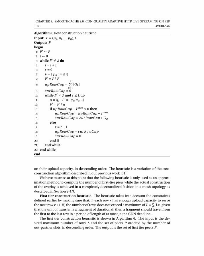
196
CHAPTER 9. SMOOTHCACHE 2.0: CDN-QUALITY ADAPTIVE HTTP LIVE STREAMING ON P2P
OVERLAYS
Algorithm 6 Row construction heuristic
Input: P = (p0, p1, ..., pn),LOutput: Fbegin
1: F ′ ← P2: i ← 03: while F ′ 6= ; do4: i = i +15: r = 06: F = { pn : n ≤ i }7: F ′ = P \ F
8: upRowC ap =F∑
k=1|Ok |
9: cur RowC ap = 010: while F ′ 6= ; and r ≤ L do11: q = q0 | F ′ = {q0, q1, ...}12: F ′ = F ′ \ q13: if upRowC ap − I max > 0 then14: upRowC ap = upRowC ap − I max
15: cur RowC ap = cur RowC ap +Oq
16: else17: r = r +118: upRowC ap = cur RowC ap19: cur RowC ap = 020: end if21: end while22: end whileend
on their upload capacity, in descending order. The heuristic is a variation of the tree-construction algorithm described in our previous work [31].
We have to stress at this point that the following heuristic is only used as an approx-imation method to compute the number of first-tier piers while the actual constructionof the overlay is achieved in a completely decentralized fashion in a mesh topology asdescribed in Section 9.4.3.
First tier construction heuristic. The heuristic takes into account the constraintsdefined earlier by making sure that: i) each row r has enough upload capacity to servethe next row r +1, ii) the number of rows does not exceed a maximum of L = µ
δ , i.e. giventhat the unit of transfer is a fragment of duration δ, then a fragment should travel fromthe first to the last row in a period of length of at most µ, the CDN deadline.
The first tier construction heuristic is shown in Algorithm 6. The input is the de-sired maximum number of rows L and the set of peers P ordered by the number ofout-partner slots, in descending order. The output is the set of first tier peers F .
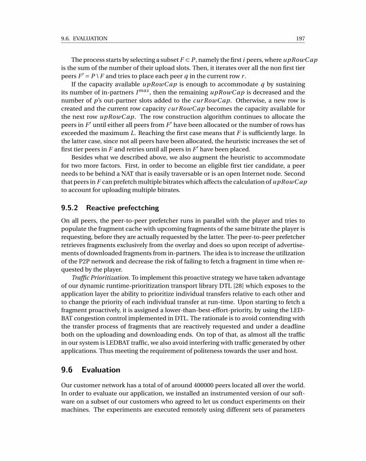
9.6. EVALUATION 197
The process starts by selecting a subset F ⊂ P , namely the first i peers, where upRowC apis the sum of the number of their upload slots. Then, it iterates over all the non first tierpeers F ′ = P \ F and tries to place each peer q in the current row r .
If the capacity available upRowC ap is enough to accommodate q by sustainingits number of in-partners I max , then the remaining upRowC ap is decreased and thenumber of p’s out-partner slots added to the cur RowC ap. Otherwise, a new row iscreated and the current row capacity cur RowC ap becomes the capacity available forthe next row upRowC ap. The row construction algorithm continues to allocate thepeers in F ′ until either all peers from F ′ have been allocated or the number of rows hasexceeded the maximum L. Reaching the first case means that F is sufficiently large. Inthe latter case, since not all peers have been allocated, the heuristic increases the set offirst tier peers in F and retries until all peers in F ′ have been placed.
Besides what we described above, we also augment the heuristic to accommodatefor two more factors. First, in order to become an eligible first tier candidate, a peerneeds to be behind a NAT that is easily traversable or is an open Internet node. Secondthat peers in F can prefetch multiple bitrates which affects the calculation of upRowC apto account for uploading multiple bitrates.
9.5.2 Reactive prefectchingOn all peers, the peer-to-peer prefetcher runs in parallel with the player and tries topopulate the fragment cache with upcoming fragments of the same bitrate the player isrequesting, before they are actually requested by the latter. The peer-to-peer prefetcherretrieves fragments exclusively from the overlay and does so upon receipt of advertise-ments of downloaded fragments from in-partners. The idea is to increase the utilizationof the P2P network and decrease the risk of failing to fetch a fragment in time when re-quested by the player.
Traffic Prioritization. To implement this proactive strategy we have taken advantageof our dynamic runtime-prioritization transport library DTL [28] which exposes to theapplication layer the ability to prioritize individual transfers relative to each other andto change the priority of each individual transfer at run-time. Upon starting to fetch afragment proactively, it is assigned a lower-than-best-effort-priority, by using the LED-BAT congestion control implemented in DTL. The rationale is to avoid contending withthe transfer process of fragments that are reactively requested and under a deadlineboth on the uploading and downloading ends. On top of that, as almost all the trafficin our system is LEDBAT traffic, we also avoid interfering with traffic generated by otherapplications. Thus meeting the requirement of politeness towards the user and host.
9.6 Evaluation
Our customer network has a total of of around 400000 peers located all over the world.In order to evaluate our application, we installed an instrumented version of our soft-ware on a subset of our customers who agreed to let us conduct experiments on theirmachines. The experiments are executed remotely using different sets of parameters
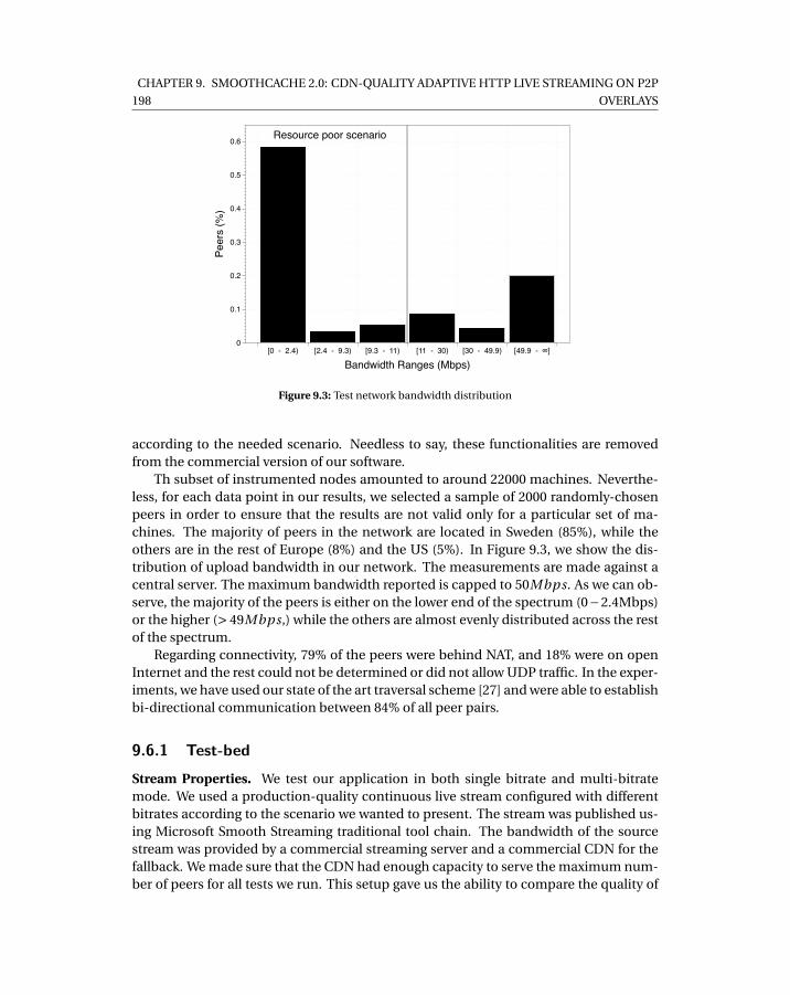
198
CHAPTER 9. SMOOTHCACHE 2.0: CDN-QUALITY ADAPTIVE HTTP LIVE STREAMING ON P2P
OVERLAYS
Resource poor scenario
Peer
s (%
)
0
0.1
0.2
0.3
0.4
0.5
0.6
Bandwidth Ranges (Mbps)[0 - 2.4) [2.4 - 9.3) [9.3 - 11) [11 - 30) [30 - 49.9) [49.9 - ∞]
Figure 9.3: Test network bandwidth distribution
according to the needed scenario. Needless to say, these functionalities are removedfrom the commercial version of our software.
Th subset of instrumented nodes amounted to around 22000 machines. Neverthe-less, for each data point in our results, we selected a sample of 2000 randomly-chosenpeers in order to ensure that the results are not valid only for a particular set of ma-chines. The majority of peers in the network are located in Sweden (85%), while theothers are in the rest of Europe (8%) and the US (5%). In Figure 9.3, we show the dis-tribution of upload bandwidth in our network. The measurements are made against acentral server. The maximum bandwidth reported is capped to 50Mbps. As we can ob-serve, the majority of the peers is either on the lower end of the spectrum (0−2.4Mbps)or the higher (> 49Mbps,) while the others are almost evenly distributed across the restof the spectrum.
Regarding connectivity, 79% of the peers were behind NAT, and 18% were on openInternet and the rest could not be determined or did not allow UDP traffic. In the exper-iments, we have used our state of the art traversal scheme [27] and were able to establishbi-directional communication between 84% of all peer pairs.
9.6.1 Test-bedStream Properties. We test our application in both single bitrate and multi-bitratemode. We used a production-quality continuous live stream configured with differentbitrates according to the scenario we wanted to present. The stream was published us-ing Microsoft Smooth Streaming traditional tool chain. The bandwidth of the sourcestream was provided by a commercial streaming server and a commercial CDN for thefallback. We made sure that the CDN had enough capacity to serve the maximum num-ber of peers for all tests we run. This setup gave us the ability to compare the quality of
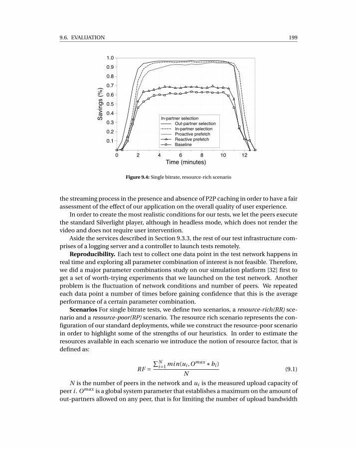
9.6. EVALUATION 199
Out-partner selectionIn-partner selectionProactive prefetchReactive prefetchBaseline
In-partner selectionSavi
ngs
(%)
0.1
0.2
0.3
0.4
0.5
0.6
0.7
0.8
0.9
1.0
Time (minutes)0 2 4 6 8 10 12
Figure 9.4: Single bitrate, resource-rich scenario
the streaming process in the presence and absence of P2P caching in order to have a fairassessment of the effect of our application on the overall quality of user experience.
In order to create the most realistic conditions for our tests, we let the peers executethe standard Silverlight player, although in headless mode, which does not render thevideo and does not require user intervention.
Aside the services described in Section 9.3.3, the rest of our test infrastructure com-prises of a logging server and a controller to launch tests remotely.
Reproducibility. Each test to collect one data point in the test network happens inreal time and exploring all parameter combination of interest is not feasible. Therefore,we did a major parameter combinations study on our simulation platform [32] first toget a set of worth-trying experiments that we launched on the test network. Anotherproblem is the fluctuation of network conditions and number of peers. We repeatedeach data point a number of times before gaining confidence that this is the averageperformance of a certain parameter combination.
Scenarios For single bitrate tests, we define two scenarios, a resource-rich(RR) sce-nario and a resource-poor(RP) scenario. The resource rich scenario represents the con-figuration of our standard deployments, while we construct the resource-poor scenarioin order to highlight some of the strengths of our heuristics. In order to estimate theresources available in each scenario we introduce the notion of resource factor, that isdefined as:
RF =∑N
i=1 mi n(ui ,Omax ∗bi )
N(9.1)
N is the number of peers in the network and ui is the measured upload capacity ofpeer i . Omax is a global system parameter that establishes a maximum on the amount ofout-partners allowed on any peer, that is for limiting the number of upload bandwidth
200
CHAPTER 9. SMOOTHCACHE 2.0: CDN-QUALITY ADAPTIVE HTTP LIVE STREAMING ON P2P
OVERLAYS
Out-partner selectionIn-partner selectioProactive prefetchReactive PrefetchBaseline
PoliciesSavi
ngs
(%)
0.1
0.2
0.3
0.4
0.5
0.6
0.7
0.8
0.9
1.0
Time (minutes)0 2 4 6 8 10 12
Figure 9.5: Single bitrate, resource-poor scenario
utilized on the best peers in the network and therefore promote politeness towards ourcustomers’ machines. Finally, bi is the stream’s bitrate. The resource factor representsthe average number of streams that a peer is able to upload to neighbors for all peers inthe network.
In the resource-rich scenario, we use a random sample of 1000 peers from the en-tirety of our test network, we let the peers watch a 688K bps bitrate stream and we limittheir Omax to 10, with a resulting resource factor of RF = 5.
In the resource-poor scenario instead, we pick a random sample of again 1000 peersfrom the lower end of the bandwidth distribution, that is from 0 up to 11Mbps. Then,we let the peers watch a stream of 1200Kbps, while the maximum number of out part-ners is Omax = 5. The resulting resource factor for this scenario is around 2.5. It isimportant to highlight that the resource factor estimation does not take into accountconnectivity limitations between peers, i.e. NATs/firewalls, and therefore it is safe toassume that the effective resource factor for both scenarios is actually lower.
For multi-bitrate tests, we use the same configuration of the resource-rich scenariobut with 3 video bitrates, that is 331, 1000, 2000 Kbps. Note that Omax is kept to a verylow number on all peers, Omax = 10 for multi-bitrate and single bitrate RR and Omax
i = 5for single bitrate RP . This is to promote fairness and spread the load of the distributionacross all peers and politeness towards the host.
9.6.2 Experiments
All experiments have a duration of 10 minutes. Peers are joined uniformly in a period oftime of one minute and churn depends on the test at end.
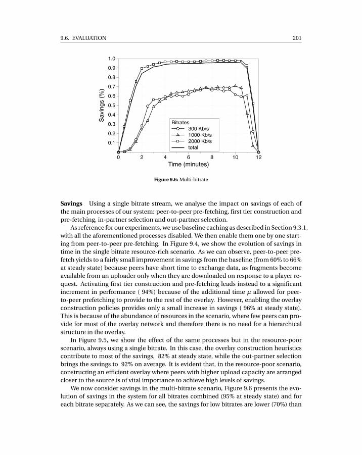
9.6. EVALUATION 201
300 Kb/s1000 Kb/s2000 Kb/stotal
BitratesSavi
ngs
(%)
0.1
0.2
0.3
0.4
0.5
0.6
0.7
0.8
0.9
1.0
Time (minutes)0 2 4 6 8 10 12
Figure 9.6: Multi-bitrate
Savings Using a single bitrate stream, we analyse the impact on savings of each ofthe main processes of our system: peer-to-peer pre-fetching, first tier construction andpre-fetching, in-partner selection and out-partner selection.
As reference for our experiments, we use baseline caching as described in Section 9.3.1,with all the aforementioned processes disabled. We then enable them one by one start-ing from peer-to-peer pre-fetching. In Figure 9.4, we show the evolution of savings intime in the single bitrate resource-rich scenario. As we can observe, peer-to-peer pre-fetch yields to a fairly small improvement in savings from the baseline (from 60% to 66%at steady state) because peers have short time to exchange data, as fragments becomeavailable from an uploader only when they are downloaded on response to a player re-quest. Activating first tier construction and pre-fetching leads instead to a significantincrement in performance ( 94%) because of the additional time µ allowed for peer-to-peer prefetching to provide to the rest of the overlay. However, enabling the overlayconstruction policies provides only a small increase in savings ( 96% at steady state).This is because of the abundance of resources in the scenario, where few peers can pro-vide for most of the overlay network and therefore there is no need for a hierarchicalstructure in the overlay.
In Figure 9.5, we show the effect of the same processes but in the resource-poorscenario, always using a single bitrate. In this case, the overlay construction heuristicscontribute to most of the savings, 82% at steady state, while the out-partner selectionbrings the savings to 92% on average. It is evident that, in the resource-poor scenario,constructing an efficient overlay where peers with higher upload capacity are arrangedcloser to the source is of vital importance to achieve high levels of savings.
We now consider savings in the multi-bitrate scenario, Figure 9.6 presents the evo-lution of savings in the system for all bitrates combined (95% at steady state) and foreach bitrate separately. As we can see, the savings for low bitrates are lower (70%) than
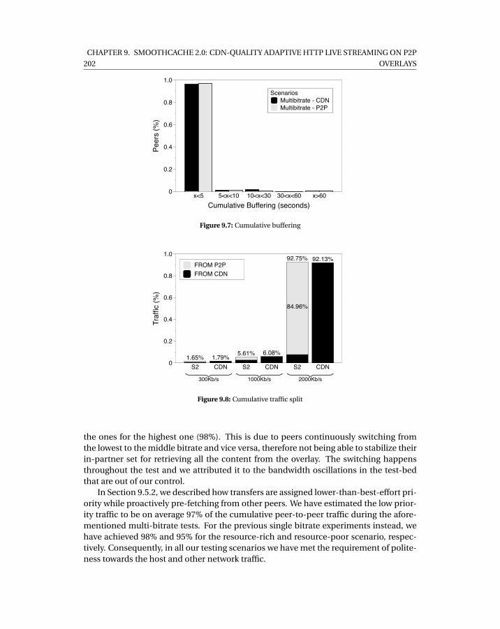
202
CHAPTER 9. SMOOTHCACHE 2.0: CDN-QUALITY ADAPTIVE HTTP LIVE STREAMING ON P2P
OVERLAYS
Multibitrate - CDNMultibitrate - P2P
Scenarios
Peer
s (%
)
0
0.2
0.4
0.6
0.8
1.0
Cumulative Buffering (seconds)x<5 5<x<10 10<x<30 30<x<60 x>60
Figure 9.7: Cumulative buffering
1.65% 1.79% 5.61% 6.08%
92.75% 92.13%FROM P2PFROM CDN
300Kb/s
1000Kb/s
2000Kb/s
84.96%
Traf
fic (%
)
0
0.2
0.4
0.6
0.8
1.0
S2 CDN S2 CDN S2 CDN
Figure 9.8: Cumulative traffic split
the ones for the highest one (98%). This is due to peers continuously switching fromthe lowest to the middle bitrate and vice versa, therefore not being able to stabilize theirin-partner set for retrieving all the content from the overlay. The switching happensthroughout the test and we attributed it to the bandwidth oscillations in the test-bedthat are out of our control.
In Section 9.5.2, we described how transfers are assigned lower-than-best-effort pri-ority while proactively pre-fetching from other peers. We have estimated the low prior-ity traffic to be on average 97% of the cumulative peer-to-peer traffic during the afore-mentioned multi-bitrate tests. For the previous single bitrate experiments instead, wehave achieved 98% and 95% for the resource-rich and resource-poor scenario, respec-tively. Consequently, in all our testing scenarios we have met the requirement of polite-ness towards the host and other network traffic.
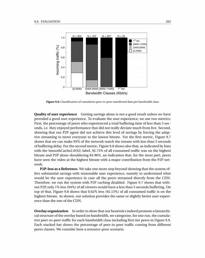
9.6. EVALUATION 203
N = 555 N = 107 N = 237 N = 23
1st tier[9000,11000][2400,9000)[0,2400)
Inco
min
g tra
ffic
(%)
0
0.2
0.4
0.6
0.8
1.0
Bandwidth Classes (Kbit/s)[0,2400) [2400,9000) [9000,11000] 1st tier
Figure 9.9: Classification of cumulative peer-to-peer transferred data per bandwidth class
Quality of user experience Getting savings alone is not a good result unless we haveprovided a good user experience. To evaluate the user experience, we use two metrics:First, the percentage of peers who experienced a total buffering time of less than 5 sec-onds, i.e. they enjoyed performance that did not really deviate much from live. Second,showing that our P2P agent did not achieve this level of savings by forcing the adap-tive streaming to move everyone to the lowest bitrate. For the first metric, Figure 9.7shows that we can make 95% of the network watch the stream with less than 5 secondsof buffering delay. For the second metric, Figure 9.8 shows also that, as indicated by barswith the SmoothCache2.0(S2) label, 92.75% of all consumed traffic was on the highestbitrate and P2P alone shouldering 84.96%, an indication that, for the most part, peershave seen the video at the highest bitrate with a major contribution from the P2P net-work.
P2P-less as a Reference. We take one more step beyond showing that the system of-fers substantial savings with reasonable user experience, namely to understand whatwould be the user experience in case all the peers streamed directly from the CDN.Therefore, we run the system with P2P caching disabled. Figure 9.7 shows that with-out P2P, only 1% less (94%) of all viewers would have a less than 5 seconds buffering. Ontop of that, Figure 9.8 shows that 0.62% less (92.13%) of all consumed traffic is on thehighest bitrate. As shown, our solution provides the same or slightly better user experi-ence than the one of the CDN.
Overlay organization In order to show that our heuristics indeed promote a hierarchi-cal structure of the overlay based on bandwidth, we categorize, for one run, the cumula-tive peer-to-peer traffic for each bandwidth class including first tier peers in Figure 9.9.Each stacked bar shows the percentage of peer-to-peer traffic coming from differentpeers classes. We consider here a resource-poor scenario.
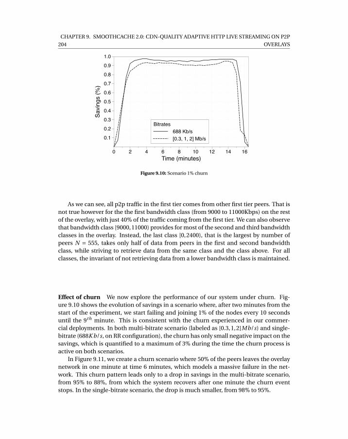
204
CHAPTER 9. SMOOTHCACHE 2.0: CDN-QUALITY ADAPTIVE HTTP LIVE STREAMING ON P2P
OVERLAYS
688 Kb/s[0.3, 1, 2] Mb/s
Bitrates
Savi
ngs
(%)
0.1
0.2
0.3
0.4
0.5
0.6
0.7
0.8
0.9
1.0
Time (minutes)0 2 4 6 8 10 12 14 16
Figure 9.10: Scenario 1% churn
As we can see, all p2p traffic in the first tier comes from other first tier peers. That isnot true however for the the first bandwidth class (from 9000 to 11000Kbps) on the restof the overlay, with just 40% of the traffic coming from the first tier. We can also observethat bandwidth class [9000,11000) provides for most of the second and third bandwidthclasses in the overlay. Instead, the last class [0,2400), that is the largest by number ofpeers N = 555, takes only half of data from peers in the first and second bandwidthclass, while striving to retrieve data from the same class and the class above. For allclasses, the invariant of not retrieving data from a lower bandwidth class is maintained.
Effect of churn We now explore the performance of our system under churn. Fig-ure 9.10 shows the evolution of savings in a scenario where, after two minutes from thestart of the experiment, we start failing and joining 1% of the nodes every 10 secondsuntil the 9th minute. This is consistent with the churn experienced in our commer-cial deployments. In both multi-bitrate scenario (labeled as [0.3,1,2]Mb/s) and single-bitrate (688K b/s, on RR configuration), the churn has only small negative impact on thesavings, which is quantified to a maximum of 3% during the time the churn process isactive on both scenarios.
In Figure 9.11, we create a churn scenario where 50% of the peers leaves the overlaynetwork in one minute at time 6 minutes, which models a massive failure in the net-work. This churn pattern leads only to a drop in savings in the multi-bitrate scenario,from 95% to 88%, from which the system recovers after one minute the churn eventstops. In the single-bitrate scenario, the drop is much smaller, from 98% to 95%.
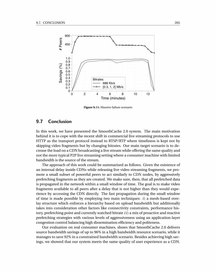
9.7. CONCLUSION 205
688 Kb/s[0.3, 1, 2] Mb/s
BitratesSavi
ngs
(%)
00.10.20.30.40.50.60.70.80.91.0
# Pe
ers
450
900
Time (minutes)0 2 4 6 8 10 12
Figure 9.11: Massive failure scenario
9.7 Conclusion
In this work, we have presented the SmoothCache 2.0 system. The main motivationbehind it is to cope with the recent shift in commercial live streaming protocols to useHTTP as the transport protocol instead to RTSP/RTP where timeliness is kept not byskipping video fragments but by changing bitrates. Our main target scenario is to de-crease the load on a CDN broadcasting a live stream while offering the same quality andnot the more typical P2P live streaming setting where a consumer machine with limitedbandwidth is the source of the stream.
The approach of this work could be summarized as follows. Given the existence ofan internal delay inside CDNs while releasing live video streaming fragments, we pro-mote a small subset of powerful peers to act similarly to CDN nodes, by aggressivelyprefetching fragments as they are created. We make sure, then, that all prefetched datais propagated in the network within a small window of time. The goal is to make videofragments available to all peers after a delay that is not higher than they would expe-rience by accessing the CDN directly. The fast propagation during the small windowof time is made possible by employing two main techniques: i ) a mesh-based over-lay structure which enforces a hierarchy based on upload bandwidth but additionallytakes into consideration other factors like connectivity constraints, performance his-tory, prefetching point and currently watched bitrate i i ) a mix of proactive and reactiveprefetching strategies with various levels of aggressiveness using an application-layercongestion control balancing high dissemination efficiency and politeness.
Our evaluation on real consumer machines, shows that SmoothCache 2.0 deliverssource bandwidth savings of up to 96% in a high bandwidth resource scenario, while itmanages to save 92% in a constrained bandwidth scenario. Besides achieving high sav-ings, we showed that our system meets the same quality of user experience as a CDN.
206
CHAPTER 9. SMOOTHCACHE 2.0: CDN-QUALITY ADAPTIVE HTTP LIVE STREAMING ON P2P
OVERLAYS
When all the peers watched the stream directly from the CDN 94% of the viewers ex-perienced a maximum delay of 5 seconds, and 92% watched the highest bitrate. Bothmetrics were matched using P2P distribution albeit with substantial bandwidth sourcesavings.
9.8 References
[1] X. Hei, C. Liang, J. Liang, Y. Liu, and K. W. Ross. Insights into PPLive: A Measure-ment Study of a Large-Scale P2P IPTV System. In Proc. of IPTV Workshop, Interna-tional World Wide Web Conference, 2006.
[2] Xinyan Zhang, Jiangchuan Liu, Bo Li, and Y. S. P. Yum. CoolStreaming/DONet: adata-driven overlay network for peer-to-peer live media streaming. In INFOCOM2005. 24th Annual Joint Conference of the IEEE Computer and Communications So-cieties.
[3] Feng Wang, Yongqiang Xiong, and Jiangchuan Liu. mtreebone: A hybrid tree/meshoverlay for application-layer live video multicast. In Distributed Computing Sys-tems, 2007. ICDCS ’07. 27th International Conference on, pages 49–49, 2007.
[4] Bittorrent live. http://live.bittorrent.com/.
[5] Amir H. Payberah, Jim Dowling, Fatemeh Rahimian, and Seif Haridi. gradientv:Market-based p2p live media streaming on the gradient overlay. In Proc. of the10th IFIP international conference on Distributed Applications and InteroperableSystems (DAIS’10), Lecture Notes in Computer Science, pages 212–225. Springer,June 2010.
[6] S. Traverso, L. Abeni, R. Birke, C. Kiraly, E. Leonardi, R. Lo Cigno, and M. Mellia. Ex-perimental comparison of neighborhood filtering strategies in unstructured p2p-tv systems. In Peer-to-Peer Computing (P2P), 2012 IEEE 12th International Confer-ence on, pages 13–24, 2012.
[7] N. Magharei, R. Rejaie, and Yang Guo. Mesh or multiple-tree: A comparative studyof live p2p streaming approaches. In INFOCOM 2007. 26th IEEE International Con-ference on Computer Communications. IEEE, pages 1424–1432, 2007.
[8] Saamer Akhshabi, Ali C. Begen, and Constantine Dovrolis. An experimental eval-uation of rate-adaptation algorithms in adaptive streaming over HTTP. In Proc. ofACM MMSys, 2011.
[9] Roberto Roverso, Sameh El-Ansary, and Seif Haridi. Smoothcache: Http-livestreaming goes peer-to-peer. In NETWORKING 2012, volume 7290 of Lecture Notesin Computer Science, pages 29–43. Springer Berlin / Heidelberg, 2012. ISBN 978-3-642-30053-0.
9.8. REFERENCES 207
[10] Bo Li, Susu Xie, Yang Qu, Gabriel Yik Keung, Chuang Lin, Jiangchuan Liu, andXinyan Zhang. Inside the new coolstreaming: Principles, measurements and per-formance implications. In INFOCOM 2008. The 27th Conference on ComputerCommunications. IEEE, pages 1031–1039. IEEE, 2008.
[11] Hao Yin, Xuening Liu, Tongyu Zhan, Vyas Sekar, Feng Qiu, Chuang Lin, Hui Zhang,and Bo Li. Livesky: Enhancing cdn with p2p. ACM Trans. Multimedia Comput.Commun. Appl., 6:16:1–16:19, August 2010. ISSN 1551-6857. URL http://doi.acm.org/10.1145/1823746.1823750.
[12] Feng Wang, Jiangchuan Liu, and Minghua Chen. Calms: Cloud-assisted live mediastreaming for globalized demands with time/region diversities. In INFOCOM, 2012Proceedings IEEE, pages 199–207, 2012.
[13] Mingchen Zhao, Paarijaat Aditya, Ang Chen, Yin Lin, Andreas Haeberlen, Peter Dr-uschel, Bruce Maggs, Bill Wishon, and Miroslav Ponec. Peer-assisted content dis-tribution in akamai netsession. In Proceedings of the 2013 conference on Internetmeasurement conference, pages 31–42. ACM, 2013.
[14] Adobe. Rtmfp for developing real-time collaboration applications, 2013. URLhttp://labs.adobe.com/technologies/cirrus/.
[15] Adobe Labs. Voddler, 2013. URL https://www.adobe.com/content/dam/Adobe/en/casestudies/air/voddler/pdfs/voddler-casestudy.pdf.
[16] Cheng Huang, Jin Li, and Keith W Ross. Peer-assisted vod: Making internet videodistribution cheap. In IPTPS, 2007.
[17] Cheng Huang, Jin Li, and Keith W. Ross. Can internet video-on-demand be prof-itable? SIGCOMM Comput. Commun. Rev., 37(4):133–144, August 2007. ISSN 0146-4833. URL http://doi.acm.org/10.1145/1282427.1282396.
[18] Liang Zhang, Fangfei Zhou, Alan Mislove, and Ravi Sundaram. Maygh: Building acdn from client web browsers. In Proceedings of the 8th ACM European Conferenceon Computer Systems, pages 281–294. ACM, 2013.
[19] Zhengye Liu, Yanming Shen, Shivendra S Panwar, Keith W Ross, and Yao Wang.Using layered video to provide incentives in p2p live streaming. In Proceedingsof the 2007 workshop on Peer-to-peer streaming and IP-TV, pages 311–316. ACM,2007.
[20] Venkata N Padmanabhan, Helen J Wang, and Philip A Chou. Resilient peer-to-peer streaming. In Network Protocols, 2003. Proceedings. 11th IEEE InternationalConference on, pages 16–27. IEEE, 2003.
[21] Luca Abeni, Arpad Bakay, Robert Birke, Gianluca Ciccarelli, Emilio Leonardi, Re-nato Lo Cigno, Csaba Kiraly, Marco Mellia, Saverio Niccolini, Jan Seedorf, Tivadar
208
CHAPTER 9. SMOOTHCACHE 2.0: CDN-QUALITY ADAPTIVE HTTP LIVE STREAMING ON P2P
OVERLAYS
Szemethy, and Giuseppe Tropea. Winestreamer(s): Flexible p2p-tv streaming ap-plications. In IEEE INFOCOM 2011 - IEEE Conference on Computer Communi-cations Workshops, Shanghai, China, 2011. URL http://peerstreamer.org/~cskiraly/preprints/kiraly-INFOCOM2011-demo-preprint.pdf.
[22] Http live streaming protocol. http://developer.apple.com/streaming/.
[23] Adobe http dynamic streaming protocol. http://www.adobe.com/products/hds-dynamic-streaming.html.
[24] Microsoft Inc. Smooth Streaming. http://www.iis.net/download/SmoothStreaming.
[25] Shao Liu, Rui Zhang-Shen, Wenjie Jiang, Jennifer Rexford, and Mung Chiang. Per-formance bounds for peer-assisted live streaming. In Proceedings of the 2008 ACMSIGMETRICS international conference on Measurement and modeling of computersystems, SIGMETRICS 2008, pages 313–324. ACM, 2008. ISBN 978-1-60558-005-0.
[26] A. Mansy and M. Ammar. Analysis of adaptive streaming for hybrid cdn/p2p livevideo systems. In Network Protocols (ICNP), 2011 19th IEEE International Confer-ence on, pages 276–285, 2011.
[27] Roberto Roverso, Sameh El-Ansary, and Seif Haridi. NATCracker: NAT Combina-tions Matter. In Proc. of 18th International Conference on Computer Communica-tions and Networks, ICCCN ’09, SF, CA, USA, 2009. IEEE Computer Society. ISBN978-1-4244-4581-3.
[28] Riccardo Reale, Roberto Roverso, Sameh El-Ansary, and Seif Haridi. DTL: DynamicTransport Library for Peer-To-Peer Applications. In In Proc. of the 12th Interna-tional Conference on Distributed Computing and Networking, ICDCN, Jan 2012.
[29] J. Rosenberg, J. Weinberger, C. Huitema, and R. Mahy. STUN - simple traversal ofuser datagram protocol (UDP) through network address translators (NATs). RFC3489, March 2003.
[30] R. Roverso, J. Dowling, and M. Jelasity. Through the wormhole: Low cost, freshpeer sampling for the internet. In Peer-to-Peer Computing (P2P), 2013 IEEE 13thInternational Conference on, 2013.
[31] R. Roverso, A. Naiem, M. Reda, M. El-Beltagy, S. El-Ansary, N. Franzen, andS. Haridi. On the feasibility of centrally-coordinated peer-to-peer live streaming. InConsumer Communications and Networking Conference (CCNC), 2011 IEEE, pages1061–1065, 2011.
[32] Roberto Roverso, Sameh El-Ansary, Alexandros Gkogkas, and Seif Haridi. Mesmer-izer: A effective tool for a complete peer-to-peer software development life-cycle.In In Proceedings of SIMUTOOLS, March 2011.

CH
AP
TE
R
10SMOOTHCACHE ENTERPRISE: ADAPTIVE
HTTP LIVE STREAMING IN LARGE
PRIVATE NETWORKS

10.1. INTRODUCTION 211
SmoothCache Enterprise: adaptive HTTP livestreaming in large private networks
Abstract
In this work, we present a distributed caching solution which addresses theproblem of efficient delivery of HTTP live streams in large private networks. Withour system, we have conducted tests on a number of pilot deployments. The largestof them, with 3000 concurrent viewers, consistently showed that our system savesmore than 90% of traffic towards the source of the stream while providing the samequality of user experience of a CDN. Another result is that our solution was able toreduce the load on the bottlenecks in the network by an average of 91.6%.
A extended abstract about this work has been published as:
Roberto Roverso, Sameh El-Ansary, and Mikael Höqvist. On HTTP live streaming in large en-terprises. In Proceedings of the ACM conference on applications, technologies, architectures,and protocols for computer communication [1]. SIGCOMM 2013, Hong Kong, China, 2013
10.1 Introduction
In the last years, the streaming industry has witnessed a shift from the RTP/RTSP stan-dard towards HTTP live, a set of protocols which all utilize HTTP for delivery of live andon-demand content in IP networks [2]. Microsoft, Adobe and Apple have developedplayers which embrace HTTP-streaming and the concept of adaptive bitrate switchingas the main approach for broadcasting. HTTP live has been adopted by content servicesand creators like Netflix, Hulu and the BBC with support across all platforms and OSs,including computers, tablets and smart phones.
The main challange of delivering HTTP-based live streams is the unicast nature ofthe HTTP protocol. This creates a potential bottleneck at the source of the stream witha linear increase in bandwidth demand as the number of viewers increases. A naturalapproach, which is also the primary solution to handle capacity issues for normal HTTPtraffic, is to introduce caching. For HTTP live this is the only alternative since there isno multicast support.
While caching of HTTP live via Content Distribution Networks (CDNs) is commonfor the open Internet, it is challenging to deploy efficiently within private networks suchas those operated by corporations or other entities. Larger private networks intercon-nect multiple network segments representing geographically distributed offices with
212
CHAPTER 10. SMOOTHCACHE ENTERPRISE: ADAPTIVE HTTP LIVE STREAMING IN LARGE
PRIVATE NETWORKS
fixed VPN links. Inside an office, the network is constructed with high capacity linksand switches. Traffic from and to the public Internet is routed through a gateway link offixed capacity or through one or more segments until a gateway link is reached.
The main bottlenecks in private networks are the VPN and gateway links which aretypically not dimensioned to sustain the load of delivering one or more streams to alarge amount of viewers at the same time. While a private CDN would dramatically im-prove the efficiency of HTTP live performance, it is hard to deploy and manage since itrequires i ) new or upgraded caching hardware to support HTTP live i i ) that each net-work segment is covered to handle the bandwidth load of all potential viewers, i i i ) han-dling of heterogeneous network infrastructure resulting from network changes such ascompany acquisitions and mergers.
In this work, we are exploring a software-based CDN for HTTP live in private net-works. We leverage the experience acquired in our previous research on improving theefficiency of delivery of HTTP streams over the Internet, where we proposed a peer-to-peer distributed caching approach [3][4]. Based on the same principles, we design anoverlay which minimizes inter-segment traffic. In doing so, we enable efficient HTTPlive streaming without the need of deploying and managing expensive and specializedhardware. In addition, we evaluate our solution in real-world deployments in privatenetworks which allows us to present unique insights into the problem at hand.
It is paramount to note that the goal of this platform is actually minimizing inter-segment traffic rather than only providing savings towards the source of the stream asin our previous work [3][4].
10.2 Challenges
In this section, we identify a set of challenges and requirements which a distributedcaching system must satisfy to be a viable solution for HTTP live streaming in a privatenetwork.
Locality and structure awareness. The overlay must be constructed to follow thephysical structure of the private network in order to keep traffic within local segmentsand offload gateway and VPN links.
Bitrate switching. An HTTP live player dynamically switches between different bi-trates for the same stream depending on the available bandwidth and host renderingcapabilities. Our solution must therefore be able to quickly handle bitrate changes.
Vendor neutrality. Support different players and protocols such as Microsoft’s SmoothStreaming, Adobe’s HTTP Dynamic Streaming and the upcoming standard MPEG-DASH.
Politeness. The delivery and relaying of content should not interfere with other ac-tivities of the user or network traffic generated by critical services.
Finally, in our industrial experience, we have found that quality of experience (QoE)is a feature that content owners are not willing to compromise on. Our service shouldthen strive to improve efficiency of distribution while providing QoE which matches theone of private CDNs.
10.3. SYSTEM OVERVIEW 213
10.3 System Overview
In HTTP live streaming protocol every fragment is fetched as an independent HTTP re-quest that could be scheduled on caching servers. The difference in our solution is thatthe caching is done at desktop machines instead of dedicated servers. The HTTP playeris directed to a local caching agent which acts as an HTTP proxy. All traffic to/from thesource of the stream as well as other peers passes by the agent. Upon a content frag-ment request, the caching agent tries to timely retrieve the data requested by the playerfrom other peers in the overlay. If a fragment cannot be retrieved from any other peeron time, the agent downloads the missing portion of the fragment from the source ofthe stream, e.g. a public CDN. By falling back to the source, we guarantee that all frag-ments are delivered on time even if the overlay network cannot retrieve such fragments,thereby guaranteeing the desired level of QoE. This process is engineered to make theagent totally transparent to the player and the streaming infrastructure. In this manner,our platform can support all HTTP-based live streaming protocols.
10.3.1 Overlay ConstructionOur distributed caching system is implemented as a self-organizing system based on amesh overlay network. When joining the system, peers are introduced to other partici-pants by a tracker. After that, they build a random overlay which is used for dissemina-tion of live peer information, e.g. throughput and playback quality. A network segmentid is provided by a central registry, with a mapping provided by the network’s owner.Peers choose their neighbors by sampling their local view and by ranking peers accord-ing to the aforementioned information. Peers make sure to partner with nodes whichare retrieving different bitrates, in order to adapt quickly to player bitrate switches.
One or more peers in a segment are promoted to act as live caches for all others inthe same segment. The promotion process is implemented either with the help of alocality-aware central service or by means of a distributed K-leader election algorithmsimilar to [5]. In order to determine the peers to be promoted, we utilize an absoluteranking based on metrics such as computational load, bandwidth and connectivity.
10.3.2 DeliveryPromoted peers are tasked with prefetching content ahead of all other peers in the samesegment. The prefetching happens either from the source of the stream or from othernodes outside their segment. We manipulate the prefetching in a way that promotedpeers retrieve the stream from the CDN only if their segment has a gateway link, as thecontent is typically provided by a source external to the private network.
As soon as a fragment is prefetched, other nodes in the segment start to retrieve itfrom the promoted peer using lower-than-best effort priority [6], as not to interfere withother critical traffic in the network.
A sample delivery overlay is shown in Figure 10.1, promoted peers are highlightedin black, while the others in orange. Arrows denote the traffic’s flow across the gateway
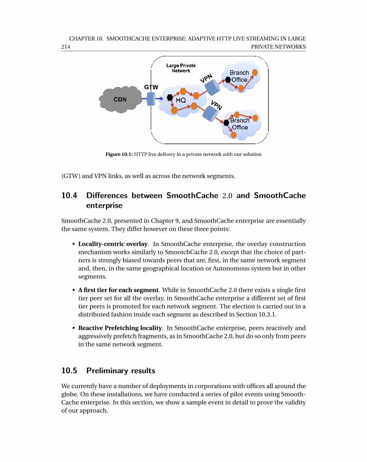
214
CHAPTER 10. SMOOTHCACHE ENTERPRISE: ADAPTIVE HTTP LIVE STREAMING IN LARGE
PRIVATE NETWORKS
Figure 10.1: HTTP live delivery in a private network with our solution
(GTW) and VPN links, as well as across the network segments.
10.4 Differences between SmoothCache 2.0 and SmoothCacheenterprise
SmoothCache 2.0, presented in Chapter 9, and SmoothCache enterprise are essentiallythe same system. They differ however on these three points:
• Locality-centric overlay. In SmoothCache enterprise, the overlay constructionmechanism works similarly to SmootchCache 2.0, except that the choice of part-ners is strongly biased towards peers that are, first, in the same network segmentand, then, in the same geographical location or Autonomous system but in othersegments.
• A first tier for each segment. While in SmoothCache 2.0 there exists a single firsttier peer set for all the overlay, in SmoothCache enterprise a different set of firsttier peers is promoted for each network segment. The election is carried out in adistributed fashion inside each segment as described in Section 10.3.1.
• Reactive Prefetching locality. In SmoothCache enterprise, peers reactively andaggressively prefetch fragments, as in SmoothCache 2.0, but do so only from peersin the same network segment.
10.5 Preliminary results
We currently have a number of deployments in corporations with offices all around theglobe. On these installations, we have conducted a series of pilot events using Smooth-Cache enterprise. In this section, we show a sample event in detail to prove the validityof our approach.
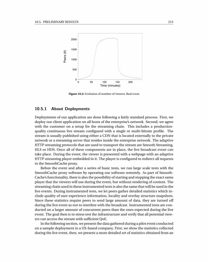
10.5. PRELIMINARY RESULTS 215
Peer
s (#
)
0
500
1000
1500
2000
Time (minutes)0 50 100 150 200
Figure 10.2: Evolution of number of viewers, Real event
10.5.1 About Deployments
Deployments of our application are done following a fairly standard process. First, wedeploy our client application on all hosts of the enterprise’s network. Second, we agreewith the customer on a setup for the streaming chain. This includes a production-quality continuous live stream configured with a single or multi-bitrate profile. Thestream is usually published using either a CDN that is located externally to the privatenetwork or a streaming server that resides inside the enterprise network. The adaptiveHTTP streaming protocols that are used to transport the stream are Smooth Streaming,HLS or HDS. Once all of these components are in place, the live broadcast event cantake place. During the event, the viewer is presented with a webpage with an adaptiveHTTP streaming player embedded in it. The player is configured to redirect all requeststo the SmoothCache proxy.
Before the event and after a series of basic tests, we run large scale tests with theSmoothCache proxy software by operating our software remotely. As part of Smooth-Cache’s functionality, there is also the possibility of starting and stopping the exact sameplayer that the viewers will use during the event, but without rendering of content. Thestreaming chain used in these instrumented tests is also the same that will be used in thelive events. During instrumented tests, we let peers gather detailed statistics which in-clude quality of user experience information, locality and overlay structure snapshots.Since these statistics require peers to send large amount of data, they are turned offduring the live event as not to interfere with the broadcast. Instrumented tests are con-ducted on a larger amount of concurrent peers than the ones expected during the liveevent. The goal then is to stress test the infrastructure and verify that all potential view-ers can access the stream with sufficient QoE.
In the following section, we present the data gathered during a pilot event conductedon a sample deployment in a US-based company. First, we show the statistics collectedduring the live event, then, we present a more detailed set of statistics obtained from an
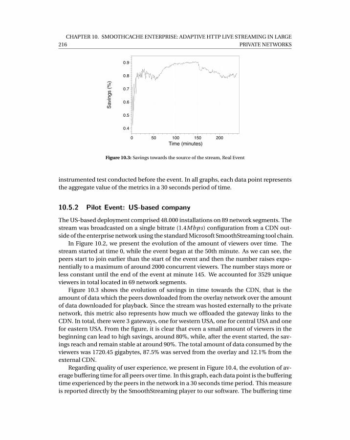
216
CHAPTER 10. SMOOTHCACHE ENTERPRISE: ADAPTIVE HTTP LIVE STREAMING IN LARGE
PRIVATE NETWORKS
Savi
ngs
(%)
0.4
0.5
0.6
0.7
0.8
0.9
Time (minutes)0 50 100 150 200
Figure 10.3: Savings towards the source of the stream, Real Event
instrumented test conducted before the event. In all graphs, each data point representsthe aggregate value of the metrics in a 30 seconds period of time.
10.5.2 Pilot Event: US-based company
The US-based deployment comprised 48.000 installations on 89 network segments. Thestream was broadcasted on a single bitrate (1.4Mbps) configuration from a CDN out-side of the enterprise network using the standard Microsoft SmoothStreaming tool chain.
In Figure 10.2, we present the evolution of the amount of viewers over time. Thestream started at time 0, while the event began at the 50th minute. As we can see, thepeers start to join earlier than the start of the event and then the number raises expo-nentially to a maximum of around 2000 concurrent viewers. The number stays more orless constant until the end of the event at minute 145. We accounted for 3529 uniqueviewers in total located in 69 network segments.
Figure 10.3 shows the evolution of savings in time towards the CDN, that is theamount of data which the peers downloaded from the overlay network over the amountof data downloaded for playback. Since the stream was hosted externally to the privatenetwork, this metric also represents how much we offloaded the gateway links to theCDN. In total, there were 3 gateways, one for western USA, one for central USA and onefor eastern USA. From the figure, it is clear that even a small amount of viewers in thebeginning can lead to high savings, around 80%, while, after the event started, the sav-ings reach and remain stable at around 90%. The total amount of data consumed by theviewers was 1720.45 gigabytes, 87.5% was served from the overlay and 12.1% from theexternal CDN.
Regarding quality of user experience, we present in Figure 10.4, the evolution of av-erage buffering time for all peers over time. In this graph, each data point is the bufferingtime experienced by the peers in the network in a 30 seconds time period. This measureis reported directly by the SmoothStreaming player to our software. The buffering time
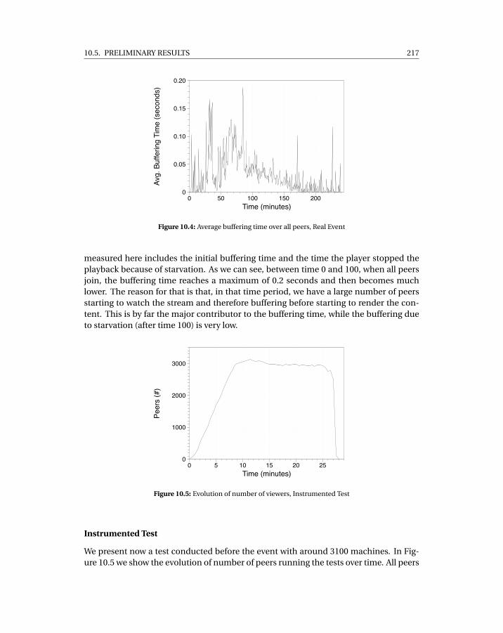
10.5. PRELIMINARY RESULTS 217
Avg.
Buf
ferin
g Ti
me
(sec
onds
)
0
0.05
0.10
0.15
0.20
Time (minutes)0 50 100 150 200
Figure 10.4: Average buffering time over all peers, Real Event
measured here includes the initial buffering time and the time the player stopped theplayback because of starvation. As we can see, between time 0 and 100, when all peersjoin, the buffering time reaches a maximum of 0.2 seconds and then becomes muchlower. The reason for that is that, in that time period, we have a large number of peersstarting to watch the stream and therefore buffering before starting to render the con-tent. This is by far the major contributor to the buffering time, while the buffering dueto starvation (after time 100) is very low.
Peer
s (#
)
0
1000
2000
3000
Time (minutes)0 5 10 15 20 25
Figure 10.5: Evolution of number of viewers, Instrumented Test
Instrumented Test
We present now a test conducted before the event with around 3100 machines. In Fig-ure 10.5 we show the evolution of number of peers running the tests over time. All peers
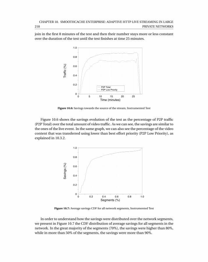
218
CHAPTER 10. SMOOTHCACHE ENTERPRISE: ADAPTIVE HTTP LIVE STREAMING IN LARGE
PRIVATE NETWORKS
join in the first 8 minutes of the test and then their number stays more or less constantover the duration of the test until the test finishes at time 25 minutes.
P2P TotalP2P Low Priority
Traf
fic (%
)
0
0.2
0.4
0.6
0.8
1.0
Time (minutes)0 5 10 15 20 25
Figure 10.6: Savings towards the source of the stream, Instrumented Test
Figure 10.6 shows the savings evolution of the test as the percentage of P2P traffic(P2P Total) over the total amount of video traffic. As we can see, the savings are similar tothe ones of the live event. In the same graph, we can also see the percentage of the videocontent that was transferred using lower than best effort priority (P2P Low Priority), asexplained in 10.3.2.
Savi
ngs
(%)
0
0.2
0.4
0.6
0.8
1.0
Segments (%)0 0.2 0.4 0.6 0.8 1.0
Figure 10.7: Average savings CDF for all network segments, Instrumented Test
In order to understand how the savings were distributed over the network segments,we present in Figure 10.7 the CDF distribution of average savings for all segments in thenetwork. In the great majority of the segments (70%), the savings were higher than 80%,while in more than 50% of the segments, the savings were more than 90%.
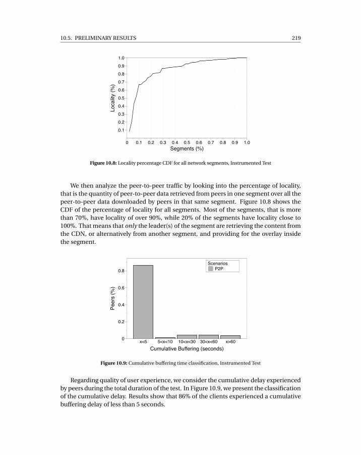
10.5. PRELIMINARY RESULTS 219
Loca
lity
(%)
0.1
0.2
0.3
0.4
0.5
0.6
0.7
0.8
0.9
1.0
Segments (%)0 0.1 0.2 0.3 0.4 0.5 0.6 0.7 0.8 0.9 1.0
Figure 10.8: Locality percentage CDF for all network segments, Instrumented Test
We then analyze the peer-to-peer traffic by looking into the percentage of locality,that is the quantity of peer-to-peer data retrieved from peers in one segment over all thepeer-to-peer data downloaded by peers in that same segment. Figure 10.8 shows theCDF of the percentage of locality for all segments. Most of the segments, that is morethan 70%, have locality of over 90%, while 20% of the segments have locality close to100%. That means that only the leader(s) of the segment are retrieving the content fromthe CDN, or alternatively from another segment, and providing for the overlay insidethe segment.
P2PScenarios
Peer
s (%
)
0
0.2
0.4
0.6
0.8
Cumulative Buffering (seconds)x<5 5<x<10 10<x<30 30<x<60 x>60
Figure 10.9: Cumulative buffering time classification, Instrumented Test
Regarding quality of user experience, we consider the cumulative delay experiencedby peers during the total duration of the test. In Figure 10.9, we present the classificationof the cumulative delay. Results show that 86% of the clients experienced a cumulativebuffering delay of less than 5 seconds.
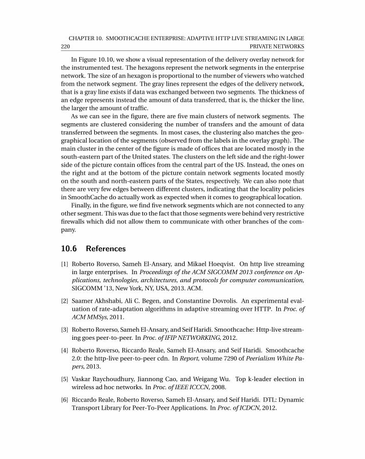
220
CHAPTER 10. SMOOTHCACHE ENTERPRISE: ADAPTIVE HTTP LIVE STREAMING IN LARGE
PRIVATE NETWORKS
In Figure 10.10, we show a visual representation of the delivery overlay network forthe instrumented test. The hexagons represent the network segments in the enterprisenetwork. The size of an hexagon is proportional to the number of viewers who watchedfrom the network segment. The gray lines represent the edges of the delivery network,that is a gray line exists if data was exchanged between two segments. The thickness ofan edge represents instead the amount of data transferred, that is, the thicker the line,the larger the amount of traffic.
As we can see in the figure, there are five main clusters of network segments. Thesegments are clustered considering the number of transfers and the amount of datatransferred between the segments. In most cases, the clustering also matches the geo-graphical location of the segments (observed from the labels in the overlay graph). Themain cluster in the center of the figure is made of offices that are located mostly in thesouth-eastern part of the United states. The clusters on the left side and the right-lowerside of the picture contain offices from the central part of the US. Instead, the ones onthe right and at the bottom of the picture contain network segments located mostlyon the south and north-eastern parts of the States, respectively. We can also note thatthere are very few edges between different clusters, indicating that the locality policiesin SmoothCache do actually work as expected when it comes to geographical location.
Finally, in the figure, we find five network segments which are not connected to anyother segment. This was due to the fact that those segments were behind very restrictivefirewalls which did not allow them to communicate with other branches of the com-pany.
10.6 References
[1] Roberto Roverso, Sameh El-Ansary, and Mikael Hoeqvist. On http live streamingin large enterprises. In Proceedings of the ACM SIGCOMM 2013 conference on Ap-plications, technologies, architectures, and protocols for computer communication,SIGCOMM ’13, New York, NY, USA, 2013. ACM.
[2] Saamer Akhshabi, Ali C. Begen, and Constantine Dovrolis. An experimental eval-uation of rate-adaptation algorithms in adaptive streaming over HTTP. In Proc. ofACM MMSys, 2011.
[3] Roberto Roverso, Sameh El-Ansary, and Seif Haridi. Smoothcache: Http-live stream-ing goes peer-to-peer. In Proc. of IFIP NETWORKING, 2012.
[4] Roberto Roverso, Riccardo Reale, Sameh El-Ansary, and Seif Haridi. Smoothcache2.0: the http-live peer-to-peer cdn. In Report, volume 7290 of Peerialism White Pa-pers, 2013.
[5] Vaskar Raychoudhury, Jiannong Cao, and Weigang Wu. Top k-leader election inwireless ad hoc networks. In Proc. of IEEE ICCCN, 2008.
[6] Riccardo Reale, Roberto Roverso, Sameh El-Ansary, and Seif Haridi. DTL: DynamicTransport Library for Peer-To-Peer Applications. In Proc. of ICDCN, 2012.
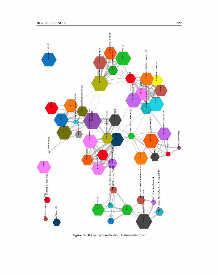
10.6. REFERENCES 221
Figure 10.10: Overlay visualization, Instrumented Test


CH
AP
TE
R
11CONCLUSIONS

225
Video streaming accounts for a large portion of the global Internet traffic. Contentproviders cope with the demand for online video content by relying on Content De-livery Networks. As demand for online video is bound to increase significantly in thecoming years and as competition between CDN services becomes fiercer, we argue thatthe CDN industry will likely turn to more cost effective solutions based on peer-to-peeroverlays. In fact, we already observe some early signs of that trend for the distribution ofvideo on demand content with companies such as Akamai pushing for adoption of Net-Session [1], a peer-assisted content distribution software, and Adobe enabling supportfor peer-to-peer video delivery in the Flash framework [2]. These solutions also pro-vide out-of-the-box support for adaptive HTTP streaming protocols which are quicklybecoming the de-facto standard for video distribution on the Internet. All major actorsin the online broadcasting business, such as Microsoft, Adobe and Apple, have devel-oped technologies which embrace HTTP as transport protocol for streaming and theconcept of adaptive bitrate switching. At the same time, most of the content servicesproviders have switched to adaptive HTTP streaming, for instance Netflix, Hulu and theBBC, and they have also added support for the new protocols across all platforms andOSs, including desktop computers, tablets and smart phones.
In this thesis, we have explored the possibility of leveraging peer-to-peer overlaysto offload CDNs when streaming live content with adaptive HTTP streaming protocols.The result of our effort is a system called SmoothCache which is the first peer-assistedsolution for the distribution of adaptive bitrate HTTP live streams. Following the peer-assisted approach, our system leverages the existing Content Delivery Network infras-tructure, as provided and without the need for integration, to assist the peer-to-peerdelivery and provide a target quality of user experience (QoE) that is the same of a CDN.
In order to build SmoothCache, we have developed a number of components whichare in their own merit novel and each of them improves on the existing state of the artin its respective research field.
We have first implemented a state-of-the art framework for the development of peer-to-peer applications called Mesmerizer [3]. The framework follows the semantics of theactor model [4], similarly to Erlang [5], Scala [6] and Kompics [7], and lets developersimplement their distributed application as a set of of components which communi-cate using events. The framework enables the execution of the developed code bothin simulation and in a real deployment. In simulation, we execute experiments on anemulated network where we accurately model multiple characteristics of physical net-works, such as the presence of Network Address Translators, network delay patternsand bandwidth allocation dynamics. In order to improve scalability and accuracy ofsimulations in our framework, we designed a novel flow-based bandwidth emulationmodel [8] which combines the max-min fairness bandwidth allocation algorithm [9]with a method called affected subgraph optimization [10]. The result is a model whichprovides accuracy that is close to that of packet-level simulators but with much higherscalability.
For deployment of SmoothCache on real networks, we developed a novel network li-brary called DTL [11] which provides reliability and on-the-fly prioritization of transfers.The library is based on the UDP protocol and enables intra- and inter-protocol priori-
226 CHAPTER 11. CONCLUSIONS
tization by combining two state of the art congestion control algorithms: LEDBAT [12]and MulTCP [13]. DTL supports a range of priority levels, that is from less-than-best-effort (LEDBAT) priority up to many times the priority of TCP. Priority can be config-ured at runtime by the application without disruptions in the flow of data and withoutthe need of connection re-establishment.
DTL also includes support for state-of-the-art Network Address Translation traversalmethods, which were also studied as part of this thesis [14]. Our work on NAT Traversalrelies on a detailed classification of NAT behavior which comprises of 27 different NATtypes. In contrast to all previous work on the subject, we argue that it is incorrect to rea-son about traversing a single NAT, instead combinations must be considered. Therefore,we provide a comprehensive study which states, for every possible NAT type combina-tion, whether direct connectivity with no relaying is feasible. On top of that, we alsodefine which specific NAT traversal technique should be used for each traversable com-bination. Our approach results in a traversal success probability that is 85% on averagein the tested scenarios and therefore much higher than previous approaches.
Because of the presence of NATs in the network, distributed discovery of new peersand collection of statistics on the overlay through peer sampling is problematic. Thatis because the probability of establishing direct connections with peers varies from onepeer to the other. To work around this limitation, we have designed a novel peer sam-pling service, the Wormhole peer sampling service (WPSS) [15]. WPSS builds a slowlychanging overlay network and executes short random walks on top of that overlay. Adescriptor containing information on a peer is originated at a node and then carried bya random walk until it is deposited when the walk terminates. WPSS improves on thestate of the art by one order of magnitude in terms of connection established per unittime while providing the same level of freshness for samples. This is achieved withoutsacrificing the desirable properties of a PSS for the Internet, such as robustness to churnand NAT-friendliness.
All of the aforementioned components are used as part of our SmoothCache systemand are employed in commercial deployments. Regarding SmoothCache itself, we havedesigned our system as a distributed cache where every peer acts as a caching nodefor live content. The main motivation behind this design is to cope with the mode ofoperation of adaptive HTTP streaming where timeliness is kept not by skipping videofragments but rather by changing bitrates. For that reason, in our system, when theplayer requests a fragment, the data is either retrieved from the neighbors of a peeror otherwise downloaded directly from the CDN in order to guarantee its delivery. Oursystem is completely oblivious to the streaming protocol and, as a consequence, it nevertries to manipulate the player behavior such as to skip fragments or force the playbackof a specific bitrate. That is in direct contrast with classical peer-to-peer systems wherethe player merely renders content and the P2P agent decides which video chunks shouldbe played and which chunks should be dropped.
Our first take on the design of the SmoothCache system, that is a distributed cachingscheme for the Internet tailored to adaptive HTTP live streaming, showed that it is possi-ble to achieve significant savings towards the source of the stream by using peer-to-peeroverlays [16]. In the second iteration of our distributed caching system [17], we were
11.1. FUTURE WORK 227
able to match the same quality of user experience levels of a CDN and achieve evenhigher savings. This was possible by letting a small subset of powerful peers, that is firsttier peers, act similarly to CDN nodes. Those nodes aggressively prefetch fragments asthey are created by the streaming server. We make sure, then, that all prefetched data ispropagated in the network within a small window of time. This window should not behigher than the delay that viewers would experience by accessing a CDN directly. In casesome fragments are not retrieved in that time window, the nodes download the data di-rectly from the CDN. Fast propagation in the peer-to-peer network during a small win-dow of time is achieved in Smoothcache by employing two techniques: i ) a mesh-basedoverlay structure which enforces a hierarchy based on upload bandwidth but addition-ally takes into consideration other factors like connectivity constraints, performancehistory and currently watched bitrate, i i ) a mix of proactive and reactive prefetchingstrategies with various levels of aggressiveness using an application-layer congestioncontrol for balancing high dissemination efficiency and politeness.
The performance of SmoothCache was evaluated in a thorough experimental studyconducted on a subset of 22000 of the around 400000 installations of our software world-wide. The study showed that SmoothCache matches the QoE of the CDN on all of thethree considered metrics: cumulative playback delay, delivered bitrate and delay fromthe playback point. Besides this result, SmoothCache was also able to consistently de-liver up to 96% savings towards the source of the stream in single bitrate scenarios and94% in multi-bitrate scenarios.
Finally, we were able to adapt our Smoothcache system to distribute adaptive HTTPlive content in large enterprise networks [18]. In this setting, links between the branchesof the enterprise and towards the rest of the Internet constitute a bottleneck during livestreaming of events. We have conducted a number of pilot deployments of the resultingsystem and, in this work, we presented in detail one of them to prove the validity ofour approach. For the considered live broadcast event, our software was installed on48.000 machines on 89 network branches of a US-based company. The event involved3529 unique viewers, with a maximum of around 2000 of them watching concurrently.Collected statistics show that SmoothCache was able to save up to 87.5% of the traffictowards the source of the stream and it also offloaded the majority of the enterprisebranches links of more than 80%.
11.1 Future Work
As future work, we would like to replace the tracker-assisted first tier election process ofSmoothCache 2.0 with a completely distributed solution. For that purpose, we intendto use an approach similar to Absolute Slicing [19]. This algorithm enables the assign-ment of peers to groups or slices of a specific size in a purely distributed manner. Theassignment is maintained under churn, and membership to one or more slices is de-cided considering a set of predefined metrics. In SmoothCache, we would use AbsoluteSlicing to form a slice which contains all possible first tier candidates.Then, we would letpeers in that group estimate how many of the candidates should become first tier peers.
228 CHAPTER 11. CONCLUSIONS
This can be done by re-designing the estimation heuristic presented in [17] to work withstatistics collected by our peer sampling layer, such as upload bandwidth distribution.Finally, the promotion of the estimated number of first tier peers would happen by cre-ating another slice containing only the candidates which are allowed to prefetch fromthe source of the stream.
We believe that a natural continuation of this work would be adding support forvideo on demand adaptive HTTP streaming to SmoothCache, similarly to Maygh [20].For that purpose, we would need to transform what is now a sliding window cachingsystem into a persistent caching system. The first step of the process is to implementlocal persistent storage of fragments. The next step is then to build a light-weight dis-tributed indexing mechanism for spreading information about piece availability of mul-tiple videos. Finally, we would need to build a replication mechanism which strives tomaintain enough copies of a video in order to maximize availability and performance.In line with the peer-assisted approach, we would rely on an existing infrastructure incase the content is not present in the peer-to-peer network. Once video-on-demand isin place, caching of general content might be considered as a possible extension to ourplatform.
Finally, it would be extremely interesting to apply the Software-defined Network-ing (SDN) paradigm [21] to improve efficiency in the delivery of adaptive HTTP livestreaming. SDN-enabled network infrastructure decouples the the control plane, whichdecides on where the traffic should be sent, from the data plane, which forwards thetraffic according to instructions from the control plane. Typically, the control planedoes not reside on routers or switches but on a centralized controller which commu-nicates remotely with the data plane using the OpenFlow protocol [22]. This simplifiestremendously network management since the centralized infrastructure allows for ef-ficient monitoring and dynamic re-configuration of the data plane [23]. Recently, wehave observed a new trend of applying the SDN principle to video distribution withRASP [24]. There authors utilize a mixture of SDN techniques and overlay networks toimprove locality of traffic in RTSP/RTP streaming. In the near future, we would like toapply the same approach to the delivery of adaptive HTTP live streaming content, thisboth on the Internet and in the setting of large private networks.
11.2 References
[1] Mingchen Zhao, Paarijaat Aditya, Ang Chen, Yin Lin, Andreas Haeberlen, Peter Dr-uschel, Bruce Maggs, Bill Wishon, and Miroslav Ponec. Peer-assisted content dis-tribution in akamai netsession. In Proceedings of the 2013 conference on Internetmeasurement conference, pages 31–42. ACM, 2013.
[2] Adobe. Rtmfp for developing real-time collaboration applications, 2013. URLhttp://labs.adobe.com/technologies/cirrus/.
[3] Roberto Roverso, Sameh El-Ansary, Alexandros Gkogkas, and Seif Haridi. Mesmer-izer: a effective tool for a complete peer-to-peer software development life-cycle.
11.2. REFERENCES 229
In Proceedings of the 4th International ACM/ICST Conference on Simulation Toolsand Techniques, SIMUTools ’11, pages 506–515, ICST, Brussels, Belgium, Belgium,2011.
[4] Gul Abdulnabi Agha. Actors: a model of concurrent computation in distributedsystems. MIT Press, 1985.
[5] Joe Armstrong. Erlang - a survey of the language and its industrial applications. InIn Proceedings of the symposium on industrial applications of Prolog (INAP96). 1618, 1996.
[6] Philipp Haller and Martin Odersky. Scala actors: Unifying thread-based and event-based programming. Theor. Comput. Sci., 410(2-3):202–220, 2009. ISSN 0304-3975.
[7] C. Arad, J. Dowling, and S. Haridi. Building and evaluating p2p systems using thekompics component framework. In Peer-to-Peer Computing, 2009. P2P ’09. IEEENinth International Conference on, pages 93 –94, 2009.
[8] Alexandros Gkogkas, Roberto Roverso, and Seif Haridi. Accurate and efficient sim-ulation of bandwidth dynamics for peer-to-peer overlay networks. In Proceedingsof the 5th International ICST Conference on Performance Evaluation Methodolo-gies and Tools, VALUETOOLS ’11, pages 352–361, ICST, Brussels, Belgium, Belgium,2011. ICST (Institute for Computer Sciences, Social-Informatics and Telecommu-nications Engineering).
[9] Anh Tuan Nguyen and F. Eliassen. An efficient solution for max-min fair rate allo-cation in p2p simulation. In ICUMT ’09: Proceedings of the International Confer-ence on Ultra Modern Telecommunications Workshops, pages 1 –5, St. Petersburg,Russia, October 2009.
[10] F. Lo Piccolo, G. Bianchi, and S. Cassella. Efficient simulation of bandwidth alloca-tion dynamics in p2p networks. In GLOBECOM ’06: Proceedings of the 49th GlobalTelecommunications Conference, pages 1–6, San Franscisco, California, November2006.
[11] Riccardo Reale, Roberto Roverso, Sameh El-Ansary, and Seif Haridi. Dtl: dynamictransport library for peer-to-peer applications. In Distributed Computing and Net-working, pages 428–442. Springer, 2012.
[12] Ledbat ietf draft. http://tools.ietf.org/html/draft-ietf-ledbat-congestion-03, July 2010.
[13] Masayoshi Nabeshima. Performance evaluation of multcp in high-speed wide areanetworks. IEICE Transactions, 88-B(1):392–396, 2005.
[14] Roberto Roverso, Sameh El-Ansary, and Seif Haridi. NATCracker: NAT Combina-tions Matter. In Proceedings of 18th International Conference on Computer Com-munications and Networks 2009, ICCCN ’09, pages 1–7, San Francisco, CA, USA,2009. IEEE Computer Society. ISBN 978-1-4244-4581-3.
230 CHAPTER 11. CONCLUSIONS
[15] R. Roverso, J. Dowling, and M. Jelasity. Through the wormhole: Low cost, freshpeer sampling for the internet. In Peer-to-Peer Computing (P2P), 2013 IEEE 13thInternational Conference on, 2013.
[16] Roberto Roverso, Sameh El-Ansary, and Seif Haridi. Smoothcache: Http-livestreaming goes peer-to-peer. In Robert Bestak, Lukas Kencl, LiErran Li, Joerg Wid-mer, and Hao Yin, editors, NETWORKING 2012, volume 7290 of Lecture Notes inComputer Science, pages 29–43. Springer Berlin Heidelberg, 2012. ISBN 978-3-642-30053-0.
[17] Roberto Roverso, Riccardo Reale, Sameh El-Ansary, and Seif Haridi. Smoothcache2.0: the http-live peer-to-peer cdn. In Report, volume 7290 of Peerialism WhitePapers, 2013.
[18] Roberto Roverso, Sameh El-Ansary, and Mikael Hoeqvist. On http live streamingin large enterprises. In Proceedings of the ACM SIGCOMM 2013 conference on Ap-plications, technologies, architectures, and protocols for computer communication,SIGCOMM ’13, New York, NY, USA, 2013. ACM.
[19] A. Montresor and R. Zandonati. Absolute slicing in peer-to-peer systems. In Par-allel and Distributed Processing, 2008. IPDPS 2008. IEEE International Symposiumon, pages 1–8, 2008.
[20] Liang Zhang, Fangfei Zhou, Alan Mislove, and Ravi Sundaram. Maygh: Building acdn from client web browsers. In Proceedings of the 8th ACM European Conferenceon Computer Systems, pages 281–294. ACM, 2013.
[21] Nick McKeown. Software-defined networking. INFOCOM keynote talk, Apr,2009. URL http://www.cs.rutgers.edu/~badri/552dir/papers/intro/nick09.pdf.
[22] Nick McKeown, Tom Anderson, Hari Balakrishnan, Guru Parulkar, Larry Peterson,Jennifer Rexford, Scott Shenker, and Jonathan Turner. Openflow: enabling innova-tion in campus networks. ACM SIGCOMM Computer Communication Review, 38(2):69–74, 2008.
[23] Sushant Jain, Alok Kumar, Subhasree Mandal, Joon Ong, Leon Poutievski, ArjunSingh, Subbaiah Venkata, Jim Wanderer, Junlan Zhou, Min Zhu, Jon Zolla, Urs Höl-zle, Stephen Stuart, and Amin Vahdat. B4: experience with a globally-deployedsoftware defined wan. In Proceedings of the ACM SIGCOMM 2013 conference onSIGCOMM, SIGCOMM ’13, pages 3–14, New York, NY, USA, 2013. ACM. ISBN 978-1-4503-2056-6. URL http://doi.acm.org/10.1145/2486001.2486019.
[24] David Hausheer Julius Ruckert, Jeremias Blendin. Rasp: Using openflow to pushoverlay streams into the underlay. In 13th IEEE International Conference on Peer-to-Peer Computing, University of Trento, Italy, September 2013.

Appendices
231


CH
AP
TE
R
12TRAVERSAL SEQUENCE DIAGRAMS
233
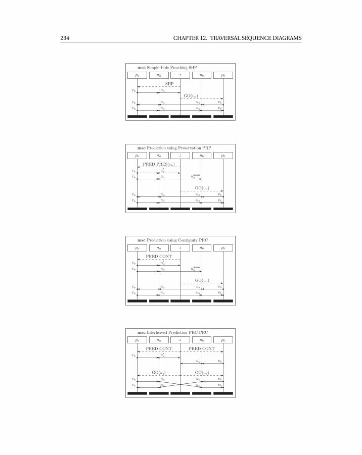
234 CHAPTER 12. TRAVERSAL SEQUENCE DIAGRAMS
pa na z nb pb
SHP
va ua
GO(ua)
vbubuava
va ua ub vb
msc Simple-Hole Punching SHP
pa na z nb pb
PRED PRES(va)
va u′a
va ua udumb
GO(ua)
vbubuava
va ua ub vb
msc Prediction using Preservation PRP
pa na z nb pb
PRED CONT
va u′a
va ua udumb
GO(ua)
vbubuava
va ua ub vb
msc Prediction using Contiguity PRC
pa na z nb pb
PRED CONT PRED CONT
va u′a
vbu′b
GO(ua)GO(ub)
vbubva ua
ub vbuava
msc Interleaved Prediction PRC-PRC


![Pioneer Avh-p4000dvd [ET]](https://img.pdfslide.net/doc/110x75/544b2f6fb1af9f88588b4aba/pioneer-avh-p4000dvd-et.jpg)