Embed Size (px)
Citation preview

AutoCAD® on Electrical SteroidsRandy Brunette – Autodesk, Inc.
MA3149 Using AutoCAD software to create electrical drawings and not using an electrical drafting package? I’ll bet you're wondering if AutoCAD® Electrical software can help. Sign up for this class to see how AutoCAD Electrical works with existing drawings and how to add electrical intelligence (such as intelligent ladders, electrical components, and automatic wire numbers) to those legacy files. We will also highlight some of the major productivity gains that are available in AutoCAD Electrical compared with stand-alone AutoCAD. Class attendees should have a basic understanding of AutoCAD.
Learning ObjectivesAt the end of this class, you will be able to:
Use AutoCAD Electrical tools to automate schematic creation
Extract reports from AutoCAD Electrical drawings
Add electrical automation and intelligence to legacy AutoCAD drawings
Modify the Swap Block and Attribute Mapping utilities
About the SpeakerRandy Brunette has joined Autodesk as an Electrical Subject Matter Expert. Randy’s duties on the CIA team include helping channel partners and customers through mentoring and understanding their business issues and finding solutions that solve their challenges.
Randy has been in the design field using Autodesk products over 27 years, with experience across multiple segments of the Manufacturing industry. He has been in an Application Engineer role for 18 years.
Prior to joining Autodesk, Randy was a sole proprietor of a consulting business specializing in AutoCAD Electrical, traveling in North America and Europe providing consulting services. Randy is a top rated speaker at Autodesk Universities, Technical Academies, and seminars. He has authored AutoCAD Electrical training manuals, videos, and other materials.

AutoCAD® on Electrical Steroids
* Preparation Notes:
1. Copy backup project files.2. Turn of display of SD Schematic Tools tab.3. Set Acad on AcadE Steroids project to active.4. Have OSNAP off.5. Copy Migration Attribute Mapping.txt to User directory.
Vista/Windows 7/8 - C:\Users\{username}\AppData\Roaming\Autodesk\AutoCAD Electrical {rel}\{ver}\enu\Support\User
6. Have powerpoint and AcadE running.7. Open Explorer to project folder.8. Change BOM reports to not show USER1. Edit format to show TAGS, QTY, SUB, MFG,
CATALOG, DESCRIPTION.9. Delete Project copy directory.
AutoCAD Electrical Overview
Built into AutoCADAutoCAD Electrical is an industry-specific version of AutoCAD software designed to meet the needs of electrical engineers designing industrial control systems. With AutoCAD Electrical, you can create control schematic drawings significantly faster than using standard AutoCAD.
AutoCAD Electrical offers a familiar AutoCAD working environment along with an intuitive menu system that provides access to many industry-specific tools that automate the electrical control systems design process.
AutoCAD Electrical is not just compatible with AutoCAD, it is AutoCAD. The functionality of AutoCAD Electrical is the same functionality of AutoCAD, just automated and enhanced. Almost every command of AutoCAD Electrical can be duplicated using standard AutoCAD commands.
The drawings created by AutoCAD Electrical are plain AutoCAD drawings. In fact, AutoCAD Electrical drawings can be editing by people using only AutoCAD, or even AutoCAD LT without corrupting or damaging the AutoCAD Electrical functionality.
2

AutoCAD® on Electrical Steroids
Blocks with AttributesAll intelligence is saved in the drawings themselves, not in an external database. This is accomplished using standard AutoCAD functionality such as blocks with attributes and xdata.
Since basic, standard functionality is being used, data is always accessible and easily available to users.
Reference files have generic formatsAutoCAD Electrical uses generic file formats such as Access databases and ASCII text files to store reference information used by and in the AutoCAD Electrical functionality. For example, the part number and pin list tables are stored in Access databases for speed and ease of use. Project file information, title block mappings, and default lookup lists are stored in ASCII text files.
AutoCAD Electrical uses these generic formats to help maintain its openness and ease of manipulation by the users. Not only does AutoCAD Electrical provide wizards and tools for editing most of the files, but the data files can be easily edited by users with any compatible program or editor. Users can even write custom programs access and manipulate the data in these files as needed for internal company processes.
Editing non-Electrical Drawings with AutoCAD ElectricalSince AutoCAD Electrical is a part of AutoCAD, editing non-electrical drawings poses no difficulties at all. All AutoCAD Electrical functionality is available depending on the level of intelligence incorporated in the drawing.
When blocks are inserted onto non-electrical lines, the lines still break, and the symbol is still inserted in the same way as if it had been inserted on an electrical wire.
Of course some functionality is not available. Wire numbers cannot be added to lines not established as wires. Data extractions such as Bill of Material reports will be incomplete unless all blocks in the drawing are converted to AutoCAD Electrical blocks.
Non-electrical drawings can be elevated to any level of AutoCAD Electrical intelligence, depending only on your requirements. You can just insert a single block, convert lines to wires or simply add wire numbers.
While AutoCAD Electrical provides many tools to add Electrical intelligence to non-Electrical drawings, it is not always best to update non-AutoCAD Electrical drawings. Sometimes it may be faster, using all of the productivity tools of AutoCAD Electrical, to simply re-create the drawing.
3

AutoCAD® on Electrical Steroids
Project ManagerThe AutoCAD Electrical Project Manager can also be used to manage non-AcadE drawings. All functionality of the Project Manager is available including the Next and Previous Project Drawings, title block updates and so on. (Hint: It can be a very useful tool for browsing drawing files!)
WD_M BlockThe existence of the WD_M block is the only thing that determines if a drawing is an AutoCAD Electrical drawing. The WD_M block does not have any graphics associated with it, and contains only invisible attributes. The block is inserted at the 0,0 point in the drawing and is invisible. The only way to see the block is to use the ATTDISP or ATTMODE commands to set the visibility of the attributes to On.
If the block does not exist, starting any AutoCAD Electrical command will prompt you to insert the block. If you deny permission, the command will still run, but every time more information or default values are required, you will be prompted again to allow the insertion of the block. Eventually you will not have to execute any more commands, or give up and allow it to be inserted.
The attributes contain the default information and settings for the drawing. Don’t worry about remembering all the attribute names and correct values to enter. The Drawing Properties command does this for you. Basically the Drawing Properties command is a specialized attribute editing tool that edits only one block, the WD_M block.
Conversion Tools Ribbon
The Conversion Tools toolbar contains many tools to help add intelligence to drawing created outside of the AutoCAD Electrical environment. Only a few are covered here.
4
AutoCAD® on Electrical Steroids
* Example – Insert WD_M Block and the Conversion Tools Ribbon
1. In the Project Manager, open, activate, and expand the project, ACAD On ACADE Steroids.
2. Expand the subfolder Convert.3. Right-click ACAD on ACADE Steroids-11.dwg. Click Open.4. On the Schematic tab, Other tools panel, click Drawing Properties.5. In the Alert dialog box, review project to drawing settings.6. Click OK.7. In the Drawing Properties dialog box, Drawing Settings tab, under Sheet Values, for
Sheet, enter 11.8. Review other drawing default settings.9. Click OK.10. Select the Conversion Tools tab.11. Review the purpose of the toolbar and some of the options.
Title Block Setup and Title Block UpdateYou can map project, drawing, and other data to any title block that is a block with attributes. Once the data is mapped to the title block you can update single or multiple attributes, for the current drawing, or across the entire project.
As a standard setup workflow, the Title Block Setup wizard allows you to map different attributes in multiple blocks. For example, this is useful when you have one block for the border and another for the revision information. However the wizard does not allow you to map the same electrical information to multiple attributes.
Here’s where a little manual editing can be very useful. For example in the class dataset, ACAD on ACADE Steroids-11.dwg has a different title block, with different attribute names, than the other files. To enable mapping to both sets of attributes at the same time, you open the WDT file using any ASCII editor and make manual edits, adding the additional mappings.
5

AutoCAD® on Electrical Steroids
In the example from the ACAD on ACADE Steroids.wdt file in the class dataset, notice there are multiple occasions where the AutoCAD Electrical information is mapped to several attributes.
1. This line contains mappings to two different title blocks.
2. This area shows the mapping of the SHEETMAX variable to both attributes, SHTS, and OFSHEET, each from different title blocks.
3. This area shows the mapping of the project description attributes to multiple title block attributes.
Caution: Using the Title Block Setup tool to map attributes after manually editing the WDT file overwrites the file with only the lines mapped in the tool. Duplicate lines and other manual edits will be lost!
* Example – Title Block Setup
1. In the Project Manager, right-click ACAD On ACADE Steroids. Select Descriptions.2. Review existing entries. Click OK.3. In the drawing, double-click the title block.4. In the Enhanced Attribute Editor dialog box, review existing attributes. Click OK.
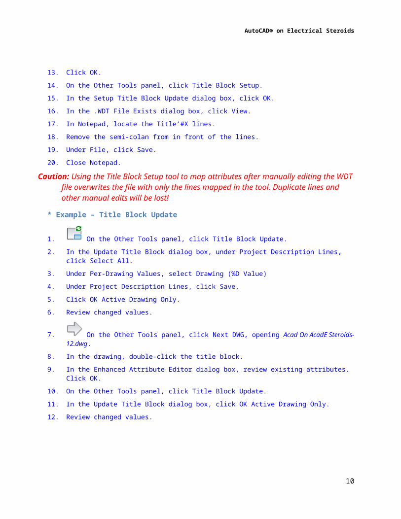
5. On the Project tab, Other Tools panel, click Title Block Setup.6. In the Setup Title Block Update dialog box, review the available options.7. Select <Project>.WDT File. Click OK.8. In the .WDT File Exists dialog box, click Edit.9. In the Title Block Setup – Project Values dialog box, review existing mapping settings.10. Under Attribute, for Date, from the selection list, select DRAWN_DATE.11. Click Drawing Values.12. In the Title Block Setup – Drawing Values dialog box, under Attribute, for Filename (No
Extension), from the selection list, select NUMBER.13. Click OK.14. On the Other Tools panel, click Title Block Setup.15. In the Setup Title Block Update dialog box, click OK.16. In the .WDT File Exists dialog box, click View.17. In Notepad, locate the Title’#X lines.18. Remove the semi-colan from in front of the lines.19. Under File, click Save.
6

AutoCAD® on Electrical Steroids
20. Close Notepad.Caution: Using the Title Block Setup tool to map attributes after manually editing the WDT file
overwrites the file with only the lines mapped in the tool. Duplicate lines and other manual edits will be lost!
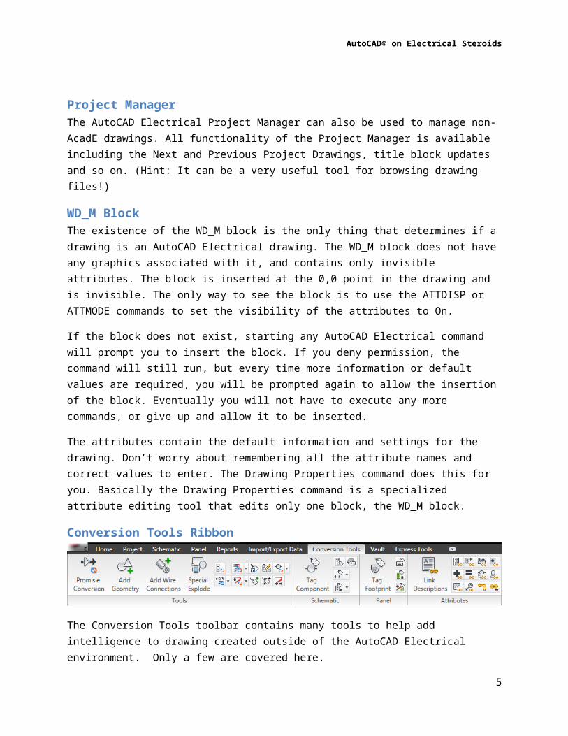
* Example – Title Block Update
1. On the Other Tools panel, click Title Block Update.2. In the Update Title Block dialog box, under Project Description Lines, click Select All.3. Under Per-Drawing Values, select Drawing (%D Value)4. Under Project Description Lines, click Save.5. Click OK Active Drawing Only.6. Review changed values.
7. On the Other Tools panel, click Next DWG, opening Acad On AcadE Steroids-12.dwg.
8. In the drawing, double-click the title block.9. In the Enhanced Attribute Editor dialog box, review existing attributes. Click OK.10. On the Other Tools panel, click Title Block Update.11. In the Update Title Block dialog box, click OK Active Drawing Only.12. Review changed values.
7

AutoCAD® on Electrical Steroids
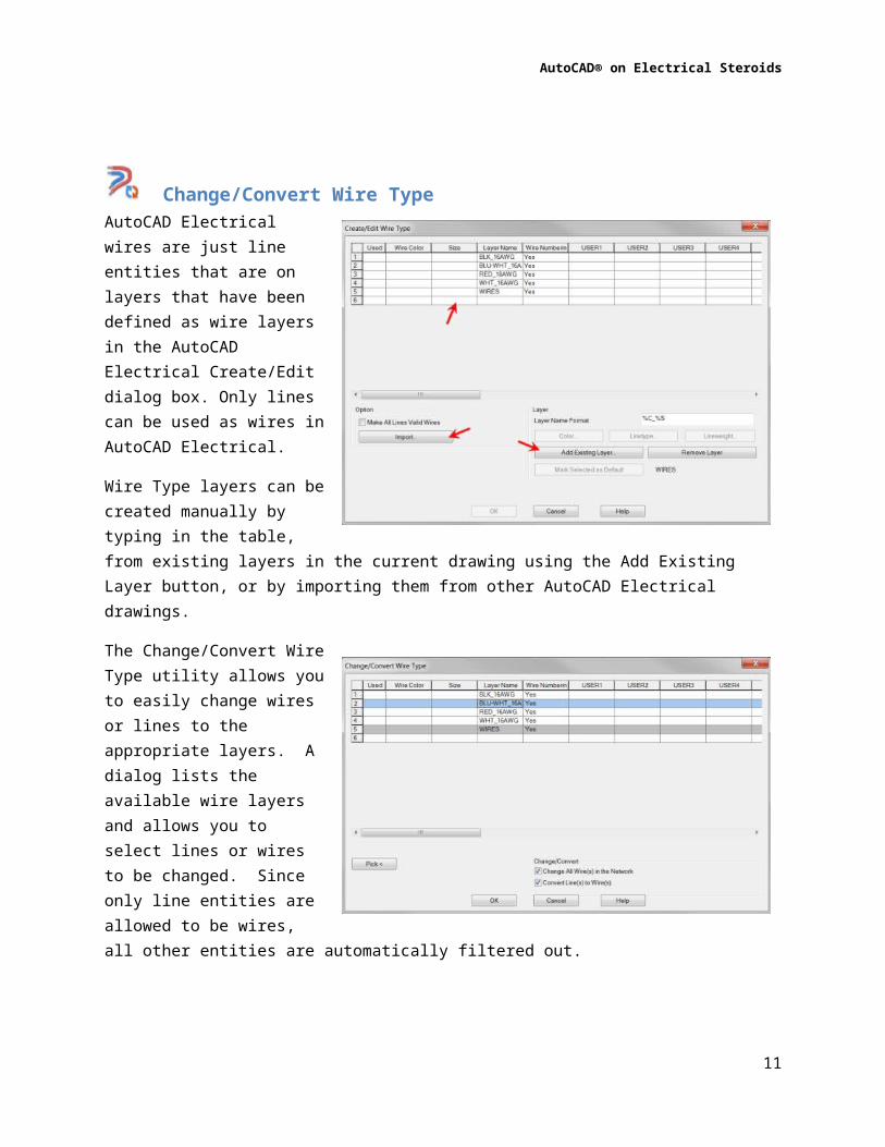
Change/Convert Wire TypeAutoCAD Electrical wires are just line entities that are on layers that have been defined as wire layers in the AutoCAD Electrical Create/Edit dialog box. Only lines can be used as wires in AutoCAD Electrical.
Wire Type layers can be created manually by typing in the table, from existing layers in the current drawing using the Add Existing Layer button, or by importing them from other AutoCAD Electrical drawings.
The Change/Convert Wire Type utility allows you to easily change wires or lines to the appropriate layers. A dialog lists the available wire layers and allows you to select lines or wires to be changed. Since only line entities are allowed to be wires, all other entities are automatically filtered out.
Note: Some tools like the Wire Layer Utility are available and used on electrical drawings also, but are assembled into a single toolbar for convenience.
* Example – Creating , Adding, and Importing Wire Types
1. Continuing on Acad On AcadE Steroids-12.dwg, on the Schematic tab, Edit Wires/Wire Numbers panel, click Create/Edit Wire Type.
Note: This drawing has only the default Wires wire type listed.2. In the Create/Edit Wire Type dialog box, in the list table, under Layer Name, enter
RED_16AWG. Press ENTER.
8

AutoCAD® on Electrical Steroids
3. Under Layer, click Color.4. In the Select Color dialog box, click RED. Click OK.5. In the Create/Edit Wire Type dialog box, click Add Existing Layer.6. In the Layers for Line “Wires” dialog box, click Pick.7. In the Select Layer for Wires dialog box, select BLK_16AWG. Click OK. Click OK again.8. In the Create/Edit Wire Type dialog box, click Import.9. In the Wire Type Import – Select Master Drawing dialog box, select Acad On AcadE
Steroids-04.dwg. Click Open.10. In the Import Wire Types dialog box, do the following:
Click Clear All. Press and hold the CTRL key. Select BLU_WHT_16AWG. Select WHT_16AWG. Click OK.
11. In the Create/Edit Wire Type dialog box, click OK.
* Example – Change/Convert Wire Type
1. On the Conversion Tools tab, Tools panel, click Change/Convert Wire Type.2. In the Change/Convert Wire Type dialog box, select BLK_16AWG. Click OK.3. In the drawing, select the upper left section of wires. (All wires above transformer.)
Press ENTER.4. Click Change/Convert Wire Type.5. In the Change/Convert Wire Type dialog box, select RED_16AWG. Click OK.6. In the drawing, select all remaining wires. Press ENTER.7. Click Change/Convert Wire Type.8. In the Change/Convert Wire Type dialog box, select WHT_16AWG. Click OK.9. In the drawing, select the right side wires. Press ENTER.10. Click Change/Convert Wire Type.11. In the Change/Convert Wire Type dialog box, select BLU/WHT_16AWG. Click OK.12. In the drawing, in the second column, select the left inner side wires. (hint, use
window.)
9
AutoCAD® on Electrical Steroids
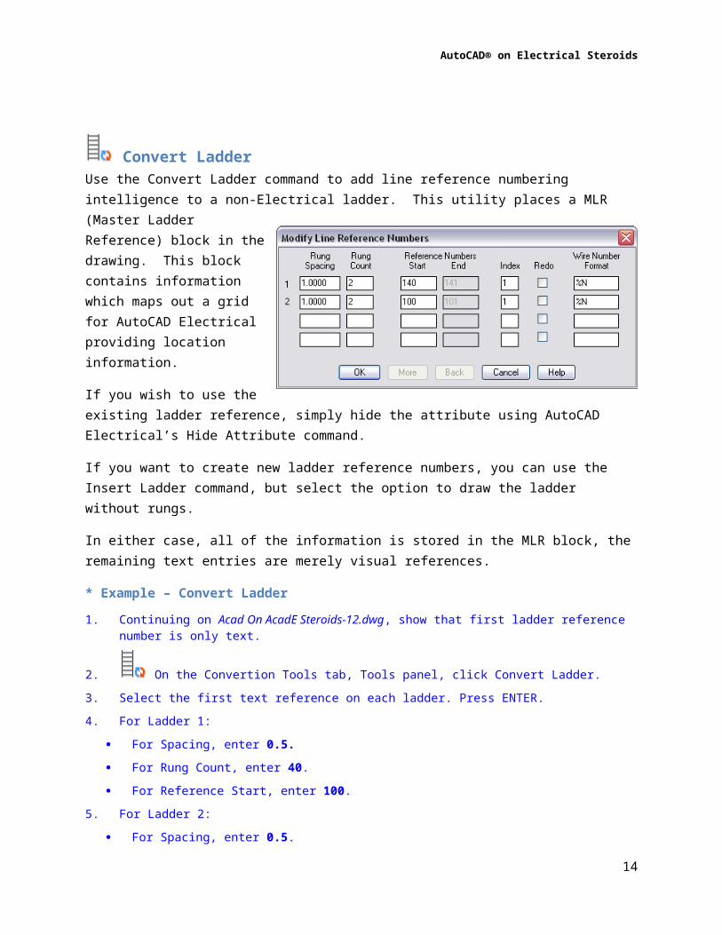
Convert LadderUse the Convert Ladder command to add line reference numbering intelligence to a non-Electrical ladder. This utility places a MLR (Master Ladder Reference) block in the drawing. This block contains information which maps out a grid for AutoCAD Electrical providing location information.
If you wish to use the existing ladder reference, simply hide the attribute using AutoCAD Electrical’s Hide Attribute command.
If you want to create new ladder reference numbers, you can use the Insert Ladder command, but select the option to draw the ladder without rungs.
In either case, all of the information is stored in the MLR block, the remaining text entries are merely visual references.
* Example – Convert Ladder
1. Continuing on Acad On AcadE Steroids-12.dwg, show that first ladder reference number is only text.
2. On the Convertion Tools tab, Tools panel, click Convert Ladder.3. Select the first text reference on each ladder. Press ENTER.4. For Ladder 1:
For Spacing, enter 0.5. For Rung Count, enter 40. For Reference Start, enter 100.
5. For Ladder 2: For Spacing, enter 0.5. For Rung Count, enter 40. For Reference Start, enter 140.
6. Click OK.7. Press Esc to end command.8. Show that first ladder reference number is now a block.
10
AutoCAD® on Electrical Steroids
* Example – Add Wire Numbers
1. On the Schematic tab, Insert Wires/Wire Numbers panel, click Wire Numbers.
2. In the Wire Tagging dialog box, select Tag/Retag Al. 3. Select Cross-Reference Signals.4. Select Line Reference.5. Click Pick Individual Wires.6. In the drawing, select all wires except 3 Phase power in upper left corner.
Convert text to wire numbersWith only a couple of selections, text can be converted into intelligent wire numbers. All you need to do is select a wire near to the text and then select the text itself. The text is converted into an intelligent wire number and associated with the wire.
If the line you select is not a wire, AutoCAD Electrical will automatically start the wire layer utility to convert the lines into wires.
* Example – Convert Text to Wire Numbers
1. In the drawing, zoom into wire numbers near transformer in top left corner. (1L3, 1L2, 2L3, 2L2)
2. Change wire 2L2 to layer 0, changing it to a normal line, (not a wire).
3. On the Conversion Tools tab, Tools panel, click Convert Text to Wire Numbers.4. Saving 2L2 for last, in the drawing, for each wire and wire number pair, select the wire
and then select the matching text number. 5. When selecting the non-wire line for 2L2, and Alert dialog box appears. Click OK.6. In the Change/Convert Wire Type dialog box, select BLK_16AWG. Click OK.7. In the drawing select both wire segments for wire 2L2. Press ENTER.8. Select 2L2.
Text is converted to fixed wire numbers.
11
AutoCAD® on Electrical Steroids
Stretch WireThe Stretch Wire command is useful for repairing gaps in your wiring. This utility is similar to AutoCAD’s lengthen or extend commands. You can automatically lengthen a line or wire until it meets a connection point on an electrical component.
Add AttributeYou can use the Add Attribute utility to add attributes individually to pre-existing blocks. You might use this tool to give extra intelligence to symbols in your drawing thereby having them show up on reports, etc.
You can even add xdata in a very similar fashion. In fact, AutoCAD Electrical has several utilities for adding, editing, and managing xdata on entities in your drawing.
* Example – Add Attribute
1. In the Project Manager, open ACAD on ACADE Steroids-14.dwg.2. Zoom in to the 1FLS flow switch on line 404.3. On the Reports tab, Schematic panel, click Reports.4. In the Schematic Reports dialog box, under Report Name, select Bill of Material.5. Under Bill of Material, select Active Drawing. Click OK.6. If prompted in the Qsave dialog box, click Always Qsave.
Note: Notice, No Data to Display message
Discuss only items listed are from swapped symbols. 7. Double-click flow switch symbol.8. In the Enhanced Attribute Editor, discuss existing attributes on Symbol, and that TAG1
and CAT are missing. Click OK.9. On the Home tab, Layers panel, set current layer to TAGS.
10. On the Conversion Tools tab, Tools panel, click Add Attribute.11. In the drawing, select flow switch 1FLS.12. In the Add Attribute dialog box, for Name, enter TAG1.
For value, enter 1FLS. For Height, enter .125. For Justification, select Center. Click OK.
13. In the drawing, select an insertion point above flow switch.
12
AutoCAD® on Electrical Steroids
14. Click Add Attribute.15. In the drawing, select flow switch 1FLS.16. In the Add Attribute dialog box, for Name, enter CAT.
For value, enter ACME-2468. For Height, enter .06. For Justification, select Center. Select Invisible. Click OK.
17. In the drawing, select an insertion point on flow switch.Note: Attribute disappears because of Invisible setting.
Note: The TAG1 attribute is required to be recognized as an ACADE symbol. The MFG and CAT attributes are required for catalogs lookups to work properly. The MFG attribute must have a value for component to appear in BOM report.
18. On the Reports tab, Schematic panel, click Reports.19. If prompted in the Qsave dialog box, click Always Qsave.20. In the Schematic Reports dialog box, under Report Name, select Bill of Material.21. Under Bill of Material, select Active Drawing. Click OK.22. Click Close.
Convert Block ToolsThe next three tools, Convert to Schematic Component, Swap/Update Block, and Block Replacement, allow you to change existing non-electrical objects and blocks into intelligent AutoCAD Electrical symbols. All three tools have functions to transfer existing attribute or text information onto the new block. Each tool works a little differently and has a different purpose.
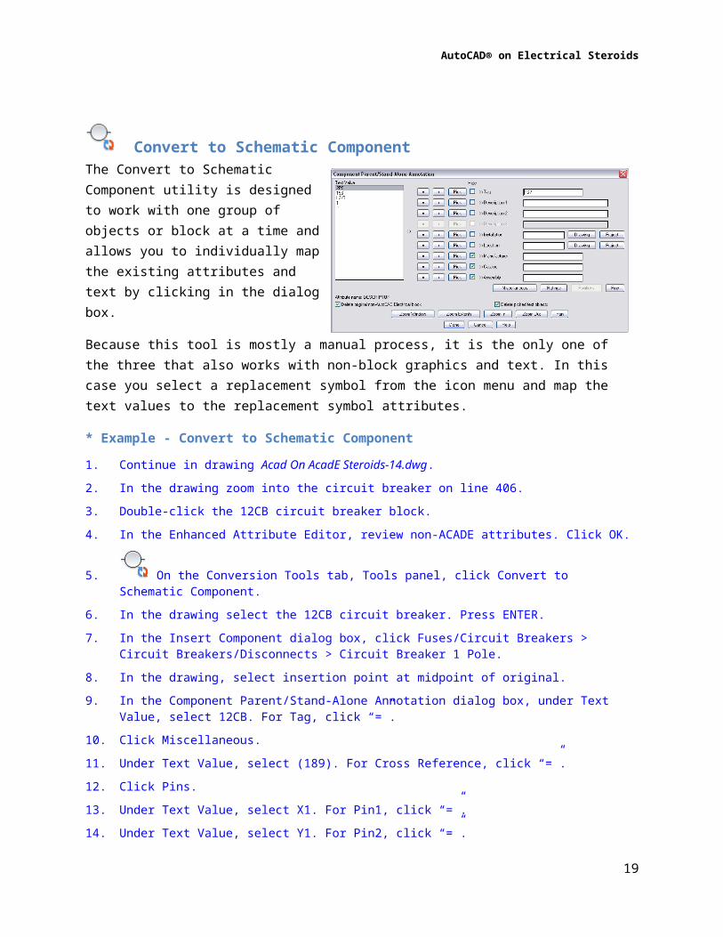
Convert to Schematic Component The Convert to Schematic Component utility is designed to work with one group of objects or block at a time and allows you to individually map the existing attributes and text by clicking in the dialog box.
Because this tool is mostly a manual process, it is the only one of the three that also works with non-block graphics and text. In this case you select a
13
AutoCAD® on Electrical Steroids
replacement symbol from the icon menu and map the text values to the replacement symbol attributes.
* Example - Convert to Schematic Component
1. Continue in drawing Acad On AcadE Steroids-14.dwg.2. In the drawing zoom into the circuit breaker on line 406.3. Double-click the 12CB circuit breaker block.4. In the Enhanced Attribute Editor, review non-ACADE attributes. Click OK.
5. On the Conversion Tools tab, Tools panel, click Convert to Schematic Component.6. In the drawing select the 12CB circuit breaker. Press ENTER.7. In the Insert Component dialog box, click Fuses/Circuit Breakers > Circuit
Breakers/Disconnects > Circuit Breaker 1 Pole.8. In the drawing, select insertion point at midpoint of original.9. In the Component Parent/Stand-Alone Annotation dialog box, under Text Value, select
12CB. For Tag, click “=”.10. Click Miscellaneous.11. Under Text Value, select (189). For Cross Reference, click “=”.12. Click Pins.13. Under Text Value, select X1. For Pin1, click “=”.14. Under Text Value, select Y1. For Pin2, click “=”.15. Click Done.
16. On the Conversion Tools tab, Tools panel, click Stretch Wire.17. In the drawing, select the two wires to connect to circuit breaker.
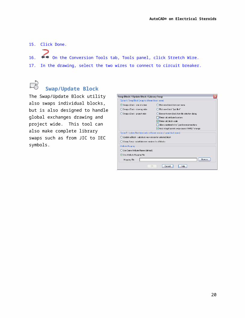
Swap/Update Block The Swap/Update Block utility also swaps individual blocks, but is also designed to handle global exchanges drawing and project wide. This tool can also make complete library swaps such as from JIC to IEC symbols.
14

AutoCAD® on Electrical Steroids
The attribute mapping for this tool is automatically completed using an external file in Excel, text, or CSV formats. This has to be set up before starting the command, but is much more efficient when making larger quantities of exchanges, especially for global drawing or project wide changes.
* Example - Swap Block
1. Continue in drawing ACAD on ACADE Steroids-14.dwg. Zoom into the top two rungs, 402-403.
2. On the Conversion Tools tab, Tools panel, Block Replacement flyout, click Swap/Update Block.
3. In the Swap Block/UpdateBlock/Library Swap dialog box, under Option A, for Swap A Block, select Drawing Wide.
4. Select Pick New Block From Icon Menu.5. Clear the Retain Old Attribute Locations checkbox.6. Clear the Retain Old Block Scale checkbox.7. Under Attribute Mapping, select Use Attribute Mapping File.8. Click Browse.9. In the Select Attribute Mapping File dialog box, for Files of Type, select .txt.10. Select Migration Attribute Mapping.txt. Click Open.11. In the Swap Block/UpdateBlock/Library Swap dialog box, click OK.
Note: Mapping file must be located in User directory.
12. From icon menu, click Pressure/Temperature > Pressure Switch, NO.
13. In the drawing, select either pressure switch on rung 402 or 403.14. Move the two new components into the gaps.
15. On the Conversion Tools tab, Tools panel, click Stretch Wire.16. In the drawing select the wires connecting to replacement switches.
15

AutoCAD® on Electrical Steroids
Block ReplacementThe Block Replacement tool is the most automated of the three tools, but also requires a little more configuration work. This tool is mainly designed to handle global exchanges drawing and project wide. You do not select the replacement blocks from the icon menu or from a library, but instead set up values in a spreadsheet to map from the old block names and attribute values to the new blocks.
A spreadsheet template file is provided with the default installation of the AutoCAD Electrical software. It is called “ace_migr_block_replace.xlt" and is located in the folder at:
C:\Users\Public\Documents\Autodesk\Acade {rel}\Support
There is also a copy of the file in the class exercise folder. You can open and edit this file and save it to any name or location you desire.
The Attribute worksheet is used for mapping the old attribute names to the corresponding AcadE attribute names. An example from the class exercise is shown. If attributes are not found on either symbol, the mapping is ignored.
The Block worksheet is where you map the old block names to the corresponding AcadE block names. You also have options to scale the AcadE block insertions to match the drawing scale, offset the insertion point of the AcadE blocks to position them correctly based on the existing block insertion point, create attribute name overrides, and attribute value overrides. An example from the class exercise is shown.
16

AutoCAD® on Electrical Steroids
* Example – Block Replacement
1. On the Quick Access toolbar, click Next Project Drawing, opening Acad On AcadE Steroids-15.dwg.
2. On the Conversion Tools tab, Tools panel, click Block Replacement.3. In the Block Replacement dialog box, select Active Drawing (All). Click OK.4. In the Select Mapping Spreadsheet dialog box, browse to the class exercise files folder.5. Right-click Acad on AcadE Steroids.xls and click Open.6. Review the mappings on both the Attribute and Block worksheets. Close Excel.7. In the Select Mapping Spreadsheet dialog box, select Acad On AcadE Steroids.xls.
Click Save.Note: Not all of the existing blocks in the drawing were mapped in the file. Those that were mapped
are replaced with AcadE blocks and attribute values are transferred appropriately.
Mark and Verify drawingsThe Mark/Verify functionality (found under the Project flyout) is useful for monitoring changes in your project drawings during the design/building process. For example, you can send drawings to your customers for approval and check for changes when they are returned. Or you can run a project wide update and check for changes than might have occurred.
When the selected drawings are processed using the Mark option, an invisible tag is placed on each entity in the drawing. Later on, using the Verity option, each entity tag is examined to determine if any changes have taken place.
The Verify report includes any changes made to an entity, including moving, editing or deletion. The report can even be fed into the Surf command, allowing you to quickly and easily view each change in context.
Warning: This is not a revision control or a document management system! Only one mark is allowed at a time. When the drawings are marked, any previous mark and any history of changes is deleted. This is a simple and easy to use tool for monitoring changes in your drawing set.
17
AutoCAD® on Electrical Steroids
Note: For Mark/Verify to detect deleted components or wire numbers, it stores information in the projects “scratch” database file. If this database is deleted, the Mark/Verify function will not be able to report deleted items. Newly inserted entities and changed items will continue to be reported.
* Example – Mark/Verify Dwgs
1. On the Quick Access toolbar, click Previous Project Drawing, opening drawing Acad On AcadE Steroids-14. Zoom into rungs 415-417.
2. On the Project tab, Project Tools panel, click Mark/Verify Dwgs.3. In the Mark and Verify dialog box, do the following:
Under Mark/Verify Drawing or Project, select Active Drawing. Under What to Do, select Mark. Select Include Non-AutoCAD Electrical Blocks Select Include Lines/Wires. Click OK.
4. In the Enter Your Initials dialog box for Initials, enter {Your Initials}.5. For Comment 1, enter Mark and Verify Example. Click OK.6. On the Home tab, Modify panel, click Erase.7. In the drawing, select circuits on rungs 416 and 417. Press ENTER.8. Click Copy.9. In the drawing, select circuit on rung 415. Press ENTER.10. For Base Point, select left quadrant of input 13 symbol.11. For Second Point, select left quadrant of input 14 and 15 symbols. Press ESC.
12. On the Project tab, Project Tools panel, click Mark/Verify Dwgs.13. In the Mark and Verify dialog box, select Active Drawing.14. Under What to Do, select Verify. Click OK.15. Review report16. Click Close.
18
AutoCAD® on Electrical Steroids
Summary
AutoCAD Electrical is built on top of and uses inherent AutoCAD functionality. This allows you to use AutoCAD Electrical to work with non-electrical drawings as well. All electrical components and symbols are generic AutoCAD entities allowing you to use non Electrical programs such as AutoCAD and AutoCAD LT to manage your drawings.
AutoCAD Electrical benefits to remember:
One time entering of most drawing information
Flexible editing with AutoCAD program environment
Quick and easy revisions to drawings
It’s Fun!
19
AutoCAD® on Electrical Steroids
Bonus - Wire Connection BlockIf you have a non-Electrical drawing and need to make minor edits such as attaching wires to an existing block, this might be the trick for you! Included in the class files are two wire connection blocks, one parent and one child. The blocks contain invisible AutoCAD Electrical attributes and a very small graphic (to allow you to select it after insertion).
Insert these at the ends of your wires and fill out the attributes appropriately. Change the lines to wires, and Presto! You now have a valid wire and component data for Wiring reports and BOMs.
* Bonus Example – Wire Connection Symbol
17. In the Project Manager, right-click ACAD on ACADE Steroids-11.dwg. Click Open.18. In the drawing, zoom in to TH1. (Lower left corner of drawing.)19. On the Schematic tab, Insert Components panel, click Icon Menu.20. In the Insert Component dialog box, for Type It, enter
HDV1_Wire_Connection_Bottom. Click OK.21. In the drawing, select an insertion point at the connection point for terminal R1.22. In the Insert/Edit Component dialog box, do the following:
For Component Tag, enter TH1. Under Description, for Line 1, enter THERMISTOR. Under Description, for Line 2, enter RELAY. Under Pins, for 1, enter R1. Click OK.
23. On the Schematic tab, Insert Components panel, click Icon Menu.24. In the Insert Component dialog box, for Type It, enter
HDV2_Wire_Connection_Bottom. Click OK.25. In the drawing, select an insertion point at the connection point for terminal R2.26. In the Insert/Edit Child Component dialog box, do the following:
For Component Tag, click Drawing. In the Active Drawing List For Family dialog box, select TH1. Click OK Under Pins, for 1, enter R2. Click OK.
27. On the Insert Wires/Wire Numbers panel, click Multiple Bus.28. In the Multiple Wire Bus dialog box, under Horizontal, for spacing, enter 0.375.29. Under Starting At, select Component (Multiple Wires). Click OK.30. In the drawing select the two wire connections previously added. Press ENTER.31. Drag the cursor down and to the right.
20

AutoCAD® on Electrical Steroids
32. At the keyboard, enter F. Press ENTER33. Position ends of wires at approximately same location as wires below.34. On the Schematic tab, Insert Wires/Wire Numbers panel, click Wire Numbers.35. In the Wire Tagging dialog box, do the following:
Under Wire Tag Mode, select Sequential For Start, enter 20. Click Drawing-wide.
36. On the Reports tab, Schematic panel, click Reports.37. In the Schematic Reports dialog box, under Report Name, select From/To. Click OK.38. If prompted, in the Qsave dialog box, click Always Qsave.39. In the Location Code Selection dialog box, on the left side, under Location Codes, click
(??).40. Repeat Step 19 for right side. Click OK.41. In Report Generator dialog box, click Close.42. In the Location Code Selection dialog box, click Cancel.
21