Embed Size (px)
Citation preview
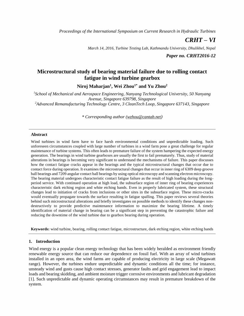
Proceedings of the International Symposium on Current Research in Hydraulic Turbines
CRHT – VI
March 14, 2016, Turbine Testing Lab, Kathmandu University, Dhulikhel, Nepal
Paper no. CRHT2016-12
Microstructural study of bearing material failure due to rolling contact
fatigue in wind turbine gearbox
Niroj Maharjan1, Wei Zhou1* and Yu Zhou2
1School of Mechanical and Aerospace Engineering, Nanyang Technological University, 50 Nanyang
Avenue, Singapore 639798, Singapore 2Advanced Remanufacturing Technology Centre, 3 CleanTech Loop, Singapore 637143, Singapore
* Corresponding author ([email protected])
Abstract
Wind turbines in wind farm have to face harsh environmental conditions and unpredictable loading. Such
unforeseen circumstances coupled with large number of turbines in a wind farm pose a great challenge for regular
maintenance of turbine systems. This often leads to premature failure of the system hampering the expected energy
generation. The bearings in wind turbine gearboxes are usually the first to fail prematurely. Thus, study of material
alterations in bearings is becoming very significant to understand the mechanisms of failure. This paper discusses
how the contact fatigue cracks appear in the bearings and the typical microstructural changes that occur due to
contact force during operation. It examines the microstructural changes that occur in inner ring of 6309 deep groove
ball bearings and 7209 angular contact ball bearings by using optical microscopy and scanning electron microscopy.
The bearing material undergoes characteristic contact fatigue failure as the result of high loading during the long-
period service. With continued operation at high load, the subsurface region of inner ring of bearing experiences
characteristic dark etching region and white etching bands. Even in properly lubricated system, these structural
changes lead to initiation of cracks from inclusions or other sites in the subsurface region. These micro-cracks
would eventually propagate towards the surface resulting in fatigue spalling. This paper reviews several theories
behind such microstructural alterations and briefly investigates on possible methods to identify these changes non-
destructively to provide predictive maintenance information to maximize the bearing lifetime. A timely
identification of material change in bearing can be a significant step in preventing the catastrophic failure and
reducing the downtime of the wind turbine due to gearbox bearing during operation.
Keywords: wind turbine, bearing, rolling contact fatigue, microstructure, dark etching region, white etching bands
1. Introduction
Wind energy is a popular clean energy technology that has been widely heralded as environment friendly
renewable energy source that can reduce our dependence on fossil fuel. With an array of wind turbines
installed in an open area, the wind farms are capable of producing electricity in large scale (Megawatt
range). However, the turbines endure unpredictable and dynamic conditions all the time; for instance,
unsteady wind and gusts cause high contact stresses, generator faults and grid engagement lead to impact
loads and bearing skidding, and ambient moisture trigger corrosive environments and lubricant degradation
[1]. Such unpredictable and dynamic operating circumstances may result in premature breakdown of the
system.
Gearbox bearings in turbine system are usually the first to succumb to damage and malfunction. According
to Jain and Hunt [2], for a typical wind turbine, gearbox failures account for about 20% of downtime,
majority of which can be attributed to fault in bearings. Even the bearings designed with utmost precision
and cleanliness may fail prematurely in just 1 or 2 years even though they are originally designed for at
least 20 years of useful life [3] due to continuous operation at large number of cycles and high contact load
by accumulation of plastic deformation [4]. A lot of researches have been carried out to understand the
causes and mechanisms of how such failures occur. Many factors such as wrong bearing alignment, high
load application, improper lubrication, presence of foreign particles, bearing material cleanliness and other
operating conditions are responsible for damage of bearing in a certain mode. The combined effect of these
parameters results in a particular mode of bearing failure.
The failure in bearings usually occur in the form of scuffing, micropitting, wear, macropitting, false
brinnelling, and surface cracking [5]. For a bearing manufactured for high speed operation and working in
well-maintained conditions, rolling contact fatigue is the ultimate mode of failure in bearings [6] i.e. if the
bearing survives all other conditions of failure, it will fail by rolling contact fatigue. The severe cyclic
contact loading results in a characteristic microstructural change in the bearing material during running-in
process which accumulate over time forming microplastic deformation [7]. The fatigue failure is generally
manifested in the form of a spall or crack. However, long before the spalling, some changes in
microstructure of bearing material occurs during operation due to the combined effect of high mechanical
and thermal loading [8], [9]. These structural changes depend on various factors like loading conditions
(contact stress, loading cycle, etc.), testing temperature which is raised mainly by plastic deformation
beneath contact surface and resistivity to tempering of the material [10].
The microstructural changes are primarily caused by the decay of parent martensite and appear as dark
etching region and 30° and 80° white etching bands due to their preferential etching characteristics [11]–
[16]. Such microstructure decay ultimately leads to localized damage and increase in probability for crack
initiation and fatigue failure. The failure usually occurs on the surface as pits formed due to dents and scars
or at subsurface level at microstructural discontinuities where the resultant stress exceeds the local yield
limit [17].
This paper discusses the general mechanism of rolling contact fatigue in wind turbine gearbox bearings.
The reason behind such failure is still not properly understood. Though many techniques have been
proposed for evaluating such premature failure, a comprehensive study and extensive laboratory experiment
to identify the main parameters driving microstructure decay is still lacking. This paper mainly focuses on
the characterization of microstructural changes that occur in bearing material during contact fatigue,
presents the preliminary experimental results, and briefly discusses the probable cause of such damage and
methods to detect it.
2. Experimental
The material used for the investigation was inner ring of 6309 Deep Groove Ball Bearing (DGBB) and
7209 Angular Contact Ball Bearing (ACBB) manufactured by SKF. The inner rings were made of AISI
52100 steel with the following nominal chemical composition (in wt. %): 0.93-1.05 C, 1.35-1.60 Cr, 0.25-
0.45 Mn, 0.15-0.35 Si, 0.10 (max.) Mo and balance Fe.
Three inner rings of 6309 bearings and 2 inner rings of 7209 bearings were used for experiment. It is to be
noted that both types of bearings were made of same material and hence underwent similar structural
changes depending on the testing criteria. The bearings were tested in following conditions as shown in
Table 1 which corresponds to the extreme operating conditions experienced in a wind farm.
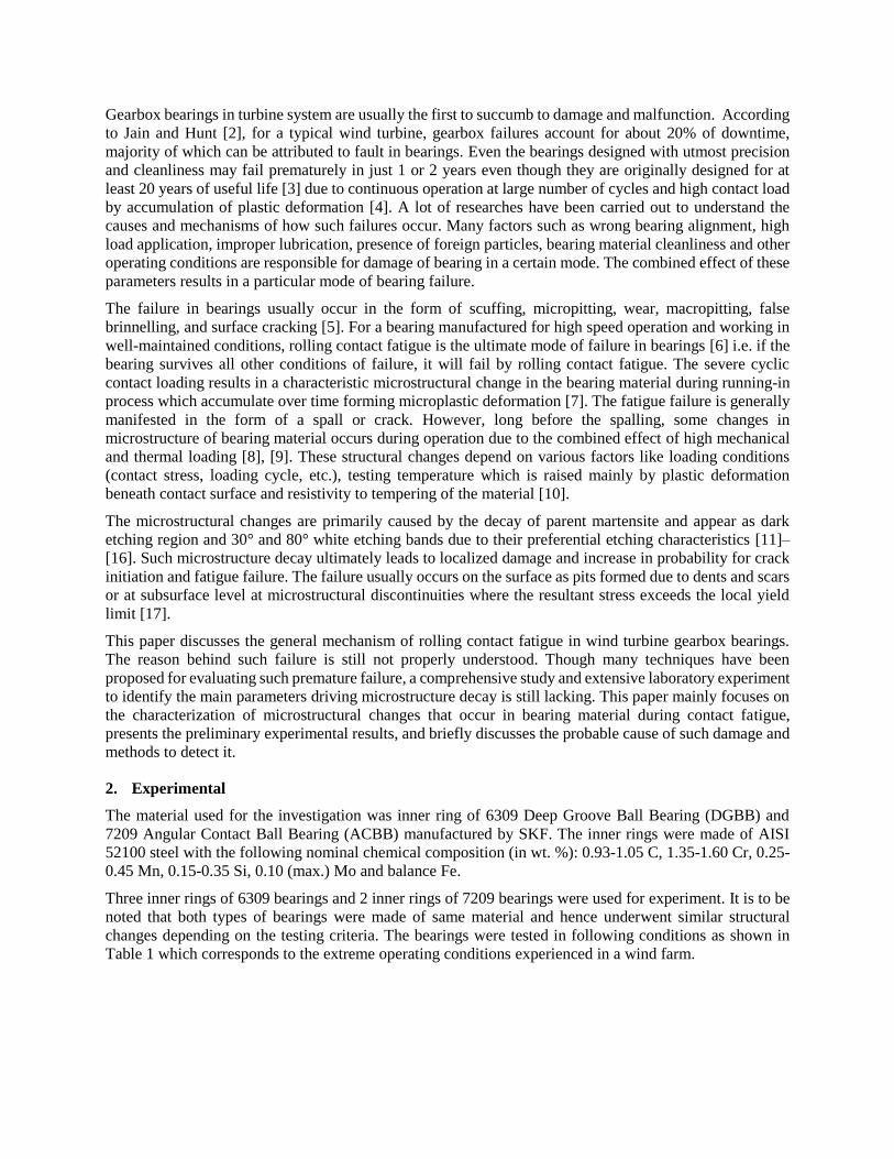
In order to study the microstructural changes, the inner rings
of bearing samples were sectioned in radial and transverse
direction (see Fig. 1) using precision diamond cutter to prepare
metallographic samples. The radial and transverse cut samples
are represented with subscripts 1 and 2 respectively in later
part of this paper.
The cut samples were ground on progressively finer grades of
emery papers up to 4000 grit and then polished with 9 µm and
3 µm diamond suspension followed by a final polish in silica
suspension. The polished samples were etched in 2% nital
(aqueous) solution for 4 seconds and cleaned with ethanol.
The microstructure obtained was analyzed using Carl Zeiss
Axioskop 2 optical microscope, scanning electron microscope
(SEM, JOEL model 5600LV) coupled with Energy Dispersive
Spectroscopy (EDS) system. The Vickers hardness of all
specimens was measured using the FM300e series Automatic
Micro-hardness Tester from Future-Tech with 500 g load and
15 s dwell time with at least 40 indents on each of the samples.
Table 1. List of samples and their testing conditions
SN Samples Composition
Contact Load for
DGBB [GPa] / Axial
Load for ACBB [kN]
C/P=2.66
Test
Temperature
[°C]
Number of
Revolution
1 A1, A2 Inner ring of DGBB 2.7 53 2.6 ͯ 106
2 B1, B2 Inner ring of DGBB 3.3 83 2.6 ͯ 106
3 C1, C2 Inner ring of DGBB 3.3 83 136 ͯ 106
4 D1,D2 Inner ring of ACBB 25 70 1033 ͯ106
5 E1, E2 Inner ring of ACBB 25 70 1100 ͯ106
3. Experimental results and discussion
3.1. Microstructures
The microstructure of inner ring of bearing is primarily composed of martensite. Martensite is hard, tough
and can resist high amount of wear and fatigue [18]. Hence, it is ideal for use in bearing. The martensite
used in bearing is often tempered to some temperature below critical point in order to strengthen its
toughness and reduce brittleness. When a bearing undergoes repeated rolling and sliding contacts (in
millions of revolution) under high loading with perfect elastohydrodynamic lubricated condition, the
volume under the contact path experiences very high stresses resulting in accumulation of microplastic
deformations [17]. These microplastic deformation manifests itself as dark etching regions and white
etching bands.
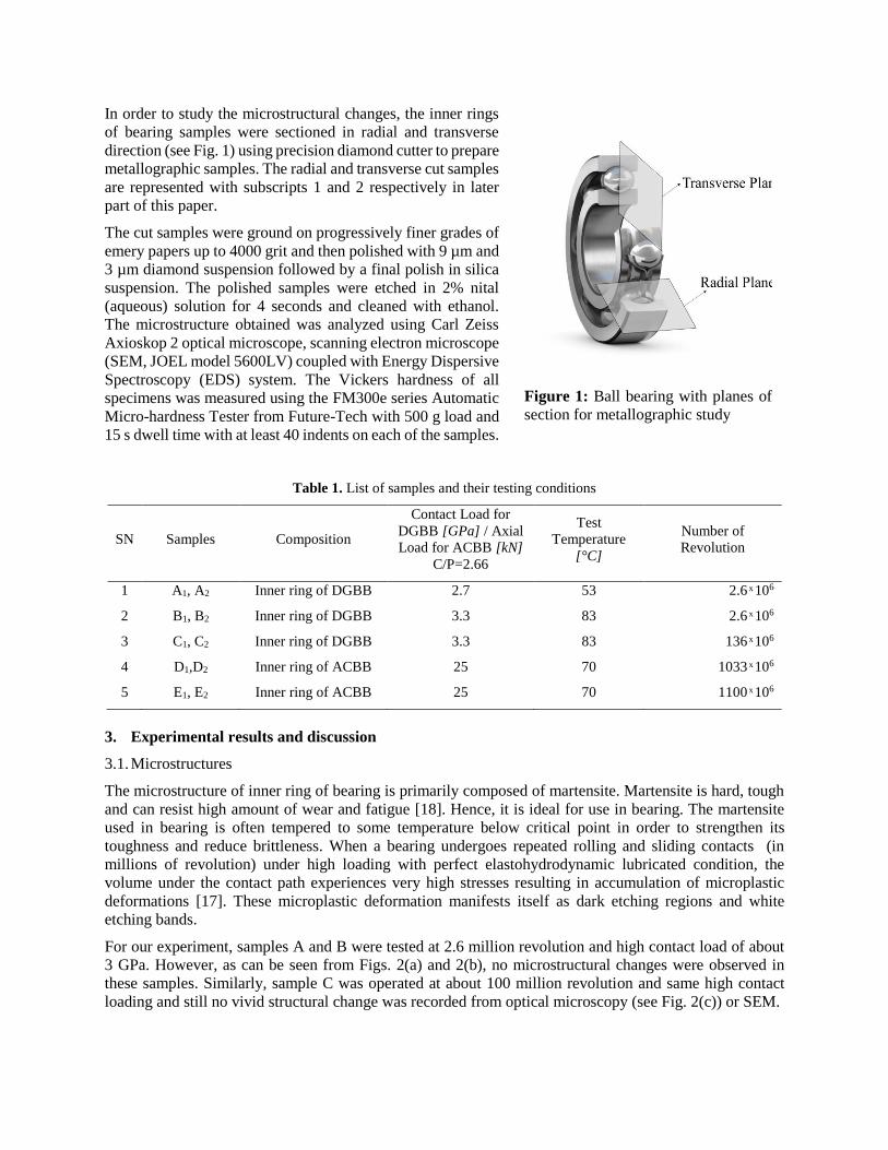
For our experiment, samples A and B were tested at 2.6 million revolution and high contact load of about
3 GPa. However, as can be seen from Figs. 2(a) and 2(b), no microstructural changes were observed in
these samples. Similarly, sample C was operated at about 100 million revolution and same high contact
loading and still no vivid structural change was recorded from optical microscopy (see Fig. 2(c)) or SEM.
Figure 1: Ball bearing with planes of
section for metallographic study
(a) (b)
(c) (d)
(e) (f)
Figure 2: Micrographs of different specimens after 2% nital etch. (a), (b), (c), (d) and (e) transverse
section of sample A,B,C,D and E respectively. (f) radial section of sample E. Note the formation of 30°
and 80° WEBs in samples D2 and E2 at the subsurface region.
However, for samples D and E, which were tested at more than 1000 million cycles of revolutions, white
bands were observed at the region of 100-400 µm below the contact surface (Figs. 2(c), 2(d), 2(e)). The
bands were of two types and were observed to overlap each other. The first one was oriented at about 30°
to the contact surface and around 2-5 µm in width with a length of approximately 50 µm. The other band
seemed to grow on top of previous white bands and was oriented approximately 80° to the contact surface
with 8-10 µm thickness. These bands were identified as commonly quoted 30° and 80° white etching bands
(WEBs) which form at subsurface layer after etching with 2% nital solution. In the radial section, these
bands were inseparable and clustered beneath the contact surface forming a white crescent at sub-surface
layer (Fig. 2(f)). The results obtained from the experiment comply with the historical data analysis by
Warhadpande et al [9] which concludes that these changes do not occur below a certain threshold loading
and number of cycles of revolution.
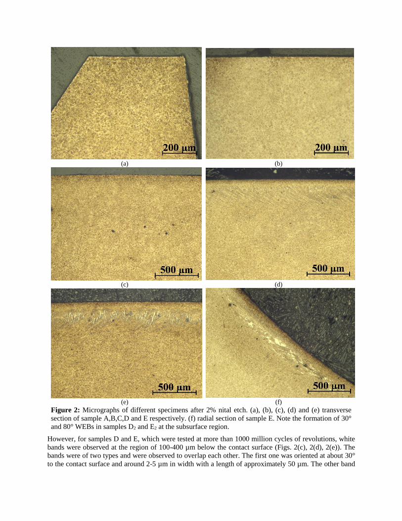
Fig. 3 shows electron images of sample E2 through the WEB region. SEM images revealed some micro-
cracks beneath the WEB region in samples D and E oriented parallel to the bands. It is understood that such
cracks initiate as a small scratch at start, but grow on to become large through summation. It is to be noted
that the maximum von Mises stress during rolling contact also occurs at the similar depth [19]. Therefore,
it can be safely assumed that these cracks are resulted from the strains developed at sub-surface during
rolling contact. The cracks further propagate to the surface and finally the bearing spalling occurs.
(a) (b)
Figure 3: SEM Images of sample E2 (a) Crack oriented parallel to 30° band (b) two cracks at sub-surface
layer propagating by addition
A significant phenomenon observed during the study was the formation of WEBs in absence of dark etching
region for samples D and E. A lot of literature suggests that dark etching regions at sub-surface layer is
followed by appearance of WEBs [9], [14], [16], [20]. While there is a good agreement to this notion, some
researchers believe that dark band formation is not a pre-requisite for WEBs appearance and these bands
can appear in absence of or prior to formation of dark etching regions [15][17] . However, very few have
proven this theory through direct experimental observation. The result obtained in this study clearly shows
that white bands can occur independently even in absence of dark bands.
3.2. Micro-hardness analysis
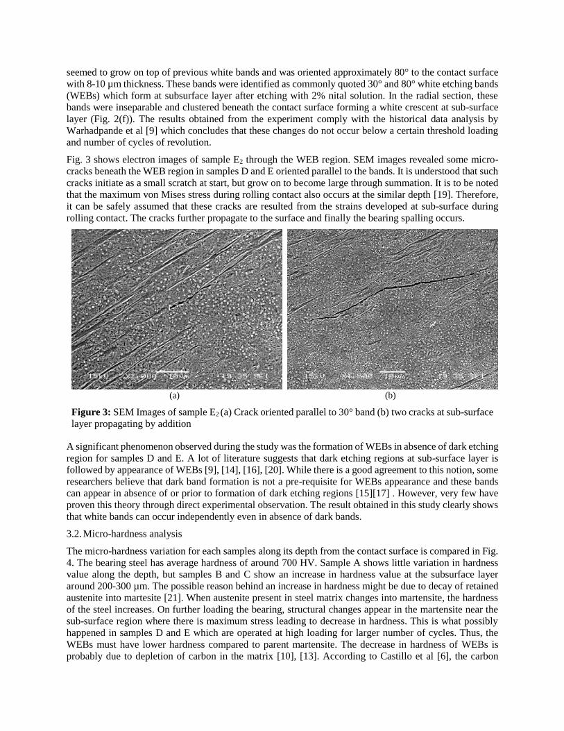
The micro-hardness variation for each samples along its depth from the contact surface is compared in Fig.
4. The bearing steel has average hardness of around 700 HV. Sample A shows little variation in hardness
value along the depth, but samples B and C show an increase in hardness value at the subsurface layer
around 200-300 µm. The possible reason behind an increase in hardness might be due to decay of retained
austenite into martesite [21]. When austenite present in steel matrix changes into martensite, the hardness
of the steel increases. On further loading the bearing, structural changes appear in the martensite near the
sub-surface region where there is maximum stress leading to decrease in hardness. This is what possibly
happened in samples D and E which are operated at high loading for larger number of cycles. Thus, the
WEBs must have lower hardness compared to parent martensite. The decrease in hardness of WEBs is
probably due to depletion of carbon in the matrix [10], [13]. According to Castillo et al [6], the carbon
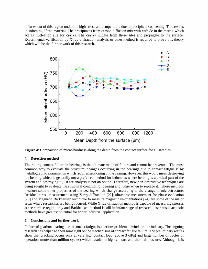
diffuses out of this region under the high stress and temperature due to precipitate coarsening. This results
in softening of the material. The precipitates from carbon diffusion mix with carbide in the matrix which
act as nucleation site for cracks. The cracks initiate from these sites and propagate to the surface.
Experimental verification by X-ray diffraction analysis or other method is required to prove this theory
which will be the further work of this research.
Figure 4: Comparison of micro-hardness along the depth from the contact surface for all samples
4. Detection method
The rolling contact failure in bearings is the ultimate mode of failure and cannot be prevented. The most
common way to evaluate the structural changes occurring in the bearings due to contact fatigue is by
metallographic examination which requires sectioning of the bearing. However, this would mean destroying
the bearing which is generally not a preferred method for industries where bearing is a critical part of the
system and destroying it just for analysis is not an option. Therefore, new non-destructive techniques are
being sought to evaluate the structural condition of bearing and judge when to replace it. These methods
measure some other properties of the bearing which change according to the change in microstructure.
Residual stress measurement using X-ray diffraction [22], ultrasonic measurement for phase evaluation
[23] and Magnetic Barkhausen technique to measure magnetic re-orientations [24] are some of the major
areas where researches are being focused. While X-ray diffraction method is capable of measuring stresses
at the surface region only and Barkhausen method is still in infant stage of research, laser based acoustic
methods have greatest potential for wider industrial application.
5. Conclusions and further work
Failure of gearbox bearing due to contact fatigue is a serious problem in wind turbine industry. The ongoing
research has helped to shed some light on the mechanisms of contact fatigue failure. The preliminary results
show that cracking occurs only at very high contact load (above 3 GPa) and large number of cycles of
operation (more than million cycles) which results in high contact and thermal pressure. Although it is
0 200 400 600 800 1000 1200550
600
650
700
750
800
Mean m
icro
hard
ness (
HV
)
Mean Depth from the surface (µm)
A
B
C
D
E
believed that DERs appear prior to formation of WEBs, the preliminary results show that WEBs can occur
independently without formation of DER. The microscopic observation reveal formation of 30° and 80°
white bands on top of each other with 80° bands appearing near the contact surface. The hardness of white
bands were found to be less than that of parent martensite and it is understood that the crack will initiate
from this region for sub-surface fatigue spalling to occur. The development of a novel non-destructive
technique to characterize such structural changes will be the next step for this research.
Acknowledgements
The authors would like to thank SKF for providing the tested bearings and the financial support from ARTC
(Advanced Remanufacturing and Technology Center), Singapore.
References
[1] Greco, A., Sheng, S., Keller, J., and Erdemir, A., “Material wear and fatigue in wind turbine Systems”
Wear, 2013; 302, 1583–1591
[2] Jain, S., and Hunt, H., “A dynamic model to predict the occurrence of skidding in wind-turbine
bearings”, J. Phys. Conf. Ser., 2011; 305, 012027
[3] Stadler, K., and Studbenrauch, K., “Premature bearing failures in industrial gearboxes”, SKF
[4] Glaeser, W.A., and Shaffer, S. J., “Contact Fatigue,” in ASM Handbook, ASM Handbook Committee,
Ed. ASM International, 1996; 19, 331–336
[5] Blau, P.J., Walker, L.R., Xu, H., Parten, R., Qu, J., Geer, T., Division, T., and Ridge, O., "Wear Analysis
of Wind Turbine Gearbox Bearings", 2010
[6] Rivera-Diaz-del-Castillo, P.E.J, “Rolling contact fatigue in bearings : phenomenology and modelling
techniques”, SKF University Technology Center, UK, 1–40
[7] Glaeser, W.A., and Shaffer, S.J., “Contact Fatigue,” ASM Handbook, 1996; 19:2, 331–336
[8] Bhargava, V., Hahn, G.T., and Rubin, C.A., “Rolling contact deformation and microstructural changes
in high strength bearing steel”, Wear, 1989; 133:1, 65–71
[9] Warhadpande, A., Sadeghi, F., and Evans, R.D., “Microstructural Alterations in Bearing Steels under
Rolling Contact Fatigue Part 1—Historical Overview”, Tribology Transactions, 2013; 56:3, 349–358
[10] Muro, H., and Tsushima, N., “Microstructural, microhardness and residual stress changes due to rolling
contact”, Wear, 1970; 15:5, 309–330
[11] Gegner, J., “Tribological Aspects of Rolling Bearing Failures,” 2011 [Online]; Available:
http://www.intechopen.com/books/tribology-lubricants-and-lubrication/tribological-aspects-of-rolling-
bearingfailure
[12] Grabulov, A., “Fundamentals of Rolling Contact Fatigue”, PhD Thesis, University of Belgrade, Serbia,
2010
[13] Sadeghi, F., Jalalahmadi, B., Slack, T.S., Raje, N., and Arakere, N.K., “A Review of Rolling Contact
Fatigue,” Journal of Tribology, 2009; 131:041403–01
[14] Swahn, H., Becker, P.C., and Vingsbo, O., “Martensite Decay during Rolling-Contact Fatigue in Ball-
Bearings”, Metallurgical Transactions A—Physical Metallurgy Material Science, 1976; 7:8, 1099–1110
[15] Lund, T., “Structural Alterations in Fatigue-tested Ball Bearing steel”, Jernkontorets Ann, 1969; 153:7,
337–343
[16] Jones, A.B., “Metallographic Observations of Ball Bearing Fatigue Phenomenon,” American Society
of Testing of Materials, Philadelphia, 1947
[17] Kang, J.H., Hosseinkhani, B., and Rivera-Diaz-del-Castillo, P.E.J., “Rolling contact fatigue in
bearings: multiscale overview”, Material Science Technology, 2012; 28, 44–49
[18] Bhadeshia, H.K.D.H., “Steels for bearings”, Prog. Mater. Sci., 2012; 57:2, 268–435
[19] Gegner, J., “Tribological Aspects of Rolling Bearing Failures” C.-H. Kuo (ed.), Tribology and
Lubricants, 2011; 33–94
[20] Bush, J.J., Grube, G.L., and Robinson, G.H., “Microstructural and residual stress changes in hardened
steel due to Rolling Contact”, Rolling Contact Phenomenon, 1962; 365–399
[21] Voskamp, A.P., “Material Response to Rolling Contact Loading,” Journal of Tribology, 1985; 107:3
[22] Fitzpatrick, M., Fry, A., Holdway, P., Kandil, F., Shackleton, J., and Suominen, L., “Determination of
Residual Stresses by X-ray Diffraction - Issue 2,” Measurement Good Practice Guide, 2005; 52
[23] Croxford, A.J., Wilcox, P.D., Drinkwater, B.W., and Nagy, P.B., “The use of non-collinear mixing for
nonlinear ultrasonic detection of plasticity and fatigue,” Journal of Acoustic Society of America, 2009;
126:5, EL117–EL122
[24] Davut, K., and Gur, C.H., “Monitoring the microstructural changes during tempering of quenched SAE
5140 steel by magnetic barkhausen noise”, Journal of Nondestructive Evaluation, 2007; 26, 107–113