Embed Size (px)
Citation preview
r '-(A L E C 0iYJ
NACA
RESEARCH MEMORANDUM
A FLOW CALORIMETER FOR DETERMINING COMBUSTION EFFICIENCY
FROM RESIDUAL ENTHALPY OF EXHAUST GASES
By Albert Evans and Robert R. Hibbard
Lewis Flight Propulsion Laboratory Cleveland, Ohio
NATIONAL ADVISORY COMMITTEE FOR AERONAUTICS
WASHINGTON March 10, 1954
https://ntrs.nasa.gov/search.jsp?R=19930088015 2018-06-14T19:43:17+00:00Z
NACA RM E53L21b
NATIONAL ADVISORY CONNITTEE FOR AERONAUTICS
RESEARCH MEMORANDUM
A FLOW CALORIMETER FOR DETERMINING CONBUSTION EFFICIENCY
PROM RESIDUAL ENTHALPY OF EAUST GASES
By Albert Evans and Robert R. Hubbard.
Flow calorimetry was investigated as a means of determining com-bustion efficiency of turbojet and ram-jet combustors by measurement of the residual enthalpy of combustion of the exhaust gases. Development of a suitable calorimeter, its calibration, and its operation are de- scribed. herein. Briefly, the calorimeter catalytically oxidizes the combustible constituents of exhaust-gas samples, and the resultant temperature rise is measured. This temperature rise is related to the residual enthalpy of combustion of the sample by previous calibration of the calorimeter. Combustion efficiency was calculated from a knowl-edge of the residual enthalpy of combustion of the exhaust gas and the combustor input enthalpy.
An accuracy of 0.2 Btu per cubic foot was obtained with prepared fuel-air mixtures having total enthalpies in the range expected for turbojet or ram-jet exhaust samples. Combustion efficiencies of single turbojet combustors measured by both the flow-calorimeter and heat-balance methods compared within 3 percentage units.
Although development of the calorimeter is incomplete, the method appears to be suitable for determining combustion efficiencies at high combustor temperatures where ordinary thermocouples cannot be used. Flow calorimetry is fundamentally more accurate than heat-balance methods at high values of combustion efficiency and can be used to verify near-100-percent efficiency data.
INTRODUCTION
The combustion efficiency of a ram-jet or turbojet engine combustor is not usually determined by measurement of the combustible content of the exhaust gases, because the method involves analysis for a number of compounds whose individual concentrations are very low. The combustible content of exhaust gases is generally found by determining the concen-trations of individual or classes of components and then summing the
2 NACA RM E53L21b
heats of combustion of each. This method Is madö difficult by the pres-ence of a large number of compounds, which represent a variety of types, as well as the low concentration of individual compounds. Combustibles known to be present in exhaust gases include primarily carbon monoxide, hydrogen, and methane; but small amounts of alcohols, formaldehyde, and formic acid have also been reported (refs. 1 to 3). Individual concen-trations reported in reference 1 vary from 0.01 to 0.50 percent by volume. Analysis of such complex and dilute mixtures by conventional macrochemical techniques is difficult, tedious, time-consuming, and uneconomical. However, exhaust-gas analysis is still of interest in evaluating combustion processes, since it can be used (1) to confirm efficiency values which are determined by other means, (2) to make de-terminations in some cases where other methods are unsuitable, and (3) to gain some insight as to the nature of the chemical processes which cause combustion inefficiency.
Exhaust-gas analysis might find wider usage if it could be more easily applied, especially, if an inexpensive device could be developed which would continuously indicate exhaust-gas composition in a flowing. stream. The use of flow calorimetry to determine residual enthalpy appeared to meet these prerequisites. Calorimetry would not require the separate determination of the various types of combustible but would require only that the combustibles be oxidized and the resultant temper-ature rise be measured. The temperature rise that is potentially avail-able upon completion of the oxidation of engine exhaust gases can be shown with a simple calculation. For example, a turbojet operating at a fuel-air ratio of 0.02 and a combustion efficiency of 90 percent ex-hausts a gas which has a residual enthalpy of combustion of 2.75 Btu per cubic foot. A temperature rise of about 700 C would be obtained upon adiabatically completing the oxidation of this gas. Although adiabatic conditions are difficult to obtain in practical systems, a substantial temperature rise can be expected. Flow calorimetry therefore appears to be a practical method for the determination of the total combustibles present.
Complete oxidation of fuel-lean systems can be obtained by either heating the gas to a high temperature (8500 to 9000 C) or to a lower temperature (5000 C) if a catalyst is used. The problems of temperature measurement, materials of construction, and thermal insulation are more easily met at the lower-temperature conditions where a catalyst is required.
In an investigation at the NACA Lewis laboratory, a catalytic, flow-type calorimeter was used for the indication of the combustible content of turbojet and ram-jet exhausts. Development of the calorimeter is briefly described in the appendix; and the resultant instrument, Its calibration, and its operation are discussed herein. Results obtained both in laboratory tests and in limited testing with exhaust-gas
NACA PM E53L21b 3
samples are presented. The possibility of using residual-enthalpy-of-combustion measurements, made by flow calorimetry, to determine com-bustion efficiency of turbojet engines and combustors is discussed.
COMBUSTIBLE CONSTITUENTS OF EXHAUST GAS
As previously stated, hydrogen, carbon monoxide, and methane are the principal combustible components in turbojet exhaust gases although hydrocarbons of molecular weights higher than that of methane are also of interest. Hydrogen and carbon monoxide are the most easily oxidized combustibles likely to be found in exhaust gases, and methane is the most difficult to oxidize. A considerable amount of data was obtained on fuel-air mixtures containing these three combustibles and, also, on mixtures containing ethane and ethylene. The latter two gases are inter-mediate between hydrogen and carbon monoxide on one hand and methane on the other in their ease of oxidizability. A calorimetric technique capable of handling these five combustibles would be expected to be effective on all the combustibles which would be present in exhanet gases. Fuel-air mixtures containing these five compounds received greater attention although some data were also obtained on mixtures containing other hydrocarbons and an alcohol.
APPARATUS
Development of the flow calorimeter was essentially a matter of finding a suitable oxidation catalyst and determining the optimum con-ditions for its use, such as temperature, flow rate, and geometry of the reaction chamber. The effects of these variables and the details of the development are described briefly in the appendix. Following the preliminary investigations, a flow calorimeter was constructed, and the most promising combination of catalyst, flow rate, and reaction-chamber diameter was incorporated. A description of the resultant in-strument, its calibration, and Its use are presented in the following paragraphs.
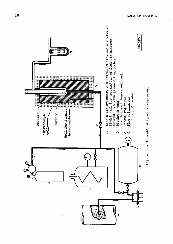
Auxiliary apparatus used to test and to calibrate the.calorimeter, to prepare fuel-air mixtures, and to measure temperatures and flow rates are shown by schematic diagram in figure 1. A size H gas cylinder filled with a 5.8 Btu per cubic foot ethylene-air mixture at a pressure of 1700 pounds per square inch was used as a standard fuel-air mixture for calibrating the calorimeter. Other fuel-air mixtures were prepared in a 12-gallon (45.4 liter) galvanized-iron tank equipped-with a motor-driven oscillating mixing arm operated through a flexible copper bellows. Turbojet-combustor exhaust-gas samples were removed from the exhaust duct by means of sampling probes and a diaphragm pump. Samples were either collected In a 33-liter stainless-steel tank or pumped. directly
NACA RM E53L21b
to the calorimeter. Flow rate was measured at room temperature and pressure downstream of the reactor by means of a capillary-type flow-meter. Temperatures were measured with iron-conatantan thermocouples and a portable potentiometer.
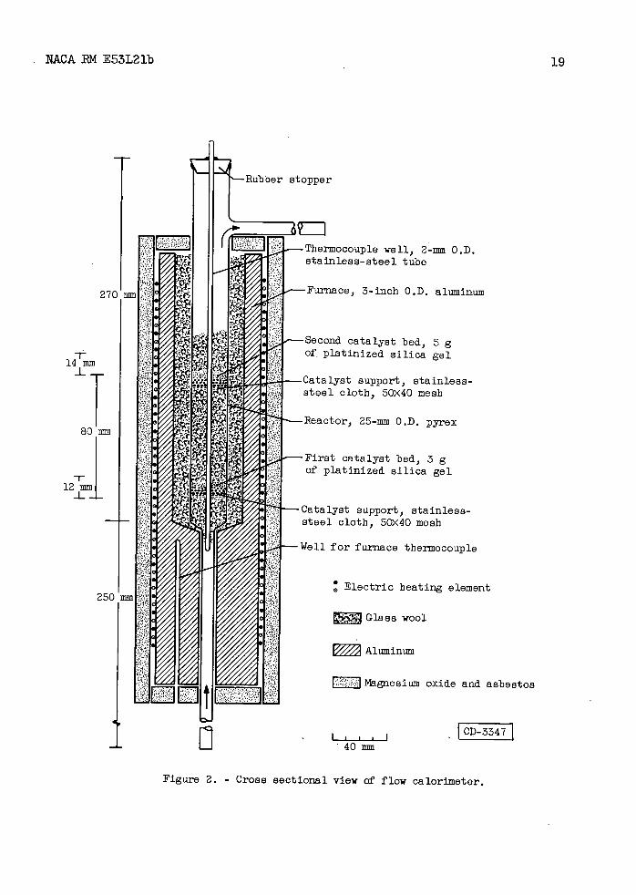
The calorimeter proper consists of a reactor, which contains the catalyst and In which oxidation takes place, and a furnace for maintain-ing the desired temperature. Principal features of the flow calorimeter are shown in figure 1 and a detailed scale drawing is presented in figure 2. The reactor, made of pyrex glass, consisted of an Inlet sec-tion, a reaction chamber, and an outlet sidearm. The relatively long Inlet section fit snugly in the furnace bore to promote efficient heat transfer so that sample gas would be heated to furnace temperature be-fore reaching the catalyst. The reaction chamber, which was 25 milli- meters in outside diameter, contained two catalyst beds; the first consisted of 3 game of platinized silica gel supported on 50x40 mesh stainless-steel wire cloth mounted 25 millimeters above the inlet section. The second catalyst bed consisting of 5 grams of the same catalyst was similarly supported 80 millimeters above the bottom of the first bed.. This distance allowed the gas temperature to return to approximately 5000 C; conditions at the first catalyst bed were thus duplicated. The second catalyst bed provided a check for completeness of oxidation at the first catalyst bed. Spaces above, below, and be-tween the catalyst beds were filled with loosely packed glass wool. The space between the reaction chamber and the aluminum block was filled with glass-wool insulation to reduce heat losses from the reactor while oxidation was taking place. A small thermocouple well, consisting of 0.080-inch-outside-diameter and a 0.014-inch-wall stainless-steel tube closed at the lower end, was mounted concentrically inside the reactor and extended through the reaction chamber and a short distance into the inlet,. It was found that temperatures inside the reactor could be meas-ured more conveniently by a single movable thermocouple in the well than by fixed thermocouple junctions, although heat losses were undoubtedly large because of the high thermal conductivity of the metal tube. The reactor was mounted vertically Inside the furnace to minimize channel-ling In the catalyst bed, and the direction of flow was upward.
An electrically heated, aluminum block furnace was used. to maintain uniform temperature distribution. Two separate electric heating ele-ments were located in double spiral grooves (not shown in fig. 2) which were cut in the outer surface of the cylindrical furnace body. Each ele-ment consisted of approximately 30 feet of 26 gauge Nichrome wire insu-lated with ceramic beads. Both elements were used to heat the furnace rapidly to operating temperature, but only one was needed to maintain a constant temperature of 5000 ±100 C. This element was connected in series with a 0 to 25 ohm variable resistor to a 110-volt supply, and it required approximately 150 watts to maintain operating temperature. A 1/8-inch-diameter hole drilled in the aluminum block (see figs. 1 and 2) provided a well for the furnace thermocouple.
NACA RM E53L2 lb
5
Preparation of Fuel-Air Mixtures
After the 12-gallon tank was throughly flushed with air, the tank was evacuated to 1.5 to 2.0 millimeters of mercury absolute. Fuel was admitted to the desired pressure; then air was added to a total pressure of 25 to 30 pounds per square inch gage. The mixture was stirred for at least 1 hour before use. The enthalpy of combustion of the mixtures, in terms of Btu per cubic foot at a temperature of 250 C and pressure of 760 millimeters of mercury absolute, was calculated from the lower heating values and the partial pressures of the combustibles in the fuel-air mixtures. Accuracy of the enthalpy values was ±0.1 Btu per cubic foot. Mixtures of lower concentration were made by dilution with air.
Calibration
The calorimeter was operated at a furnace temperature of 5000 C and a flow rate of 1.75 cubic feet per hour (see appendix). For the purpose of calibrating the calorimeter, various fuel-air mixtures of known en-thalpy were passed through the reactor and the maximum temperature rise was measured. The flameless oxidation of the fuel that occurred within the first catalyst bed resulted in a localized "hot spot" or point of maximum temperature rise along the thermocouple well. The position of this hot spot was located by means of the movable thermocouple and recorded as the distance from the bottom of the thermocouple well to the junction. In order to facilitate this measurement, a reference line was made on the thermocouple wire at the top of the well, with the junc-tion at the bottom of the well, so that vertical displacement of the line was equal to that of the junction. Maximum temperature rise was calculated from the difference between the maximum electromotive force of the thermocouple inside the reactor and that of the thermocouple in-side the furnace. All temperature-rise measurements were made at ther-mal equilibrium, which was established In 3 to 5 minutes. Temperature profile was obtained by measuring temperature rise at numerous points along the axis of the reactor. When the temperature profile along the axis of the reactor was determined with air alone at the calibration flow rate, it was found that, although the temperature profile was flat over most of the reactor length, a slight drop occurred in the region of the second catalyst bed. Since true temperature rise is the difference between temperature with oxidation and without oxidation of fuel, all temperature rises reported were corrected to the air-calibration pro-file. These corrections were less than 20 C in the region of the first catalyst bed and approximately 50 C at the second catalyst bed.
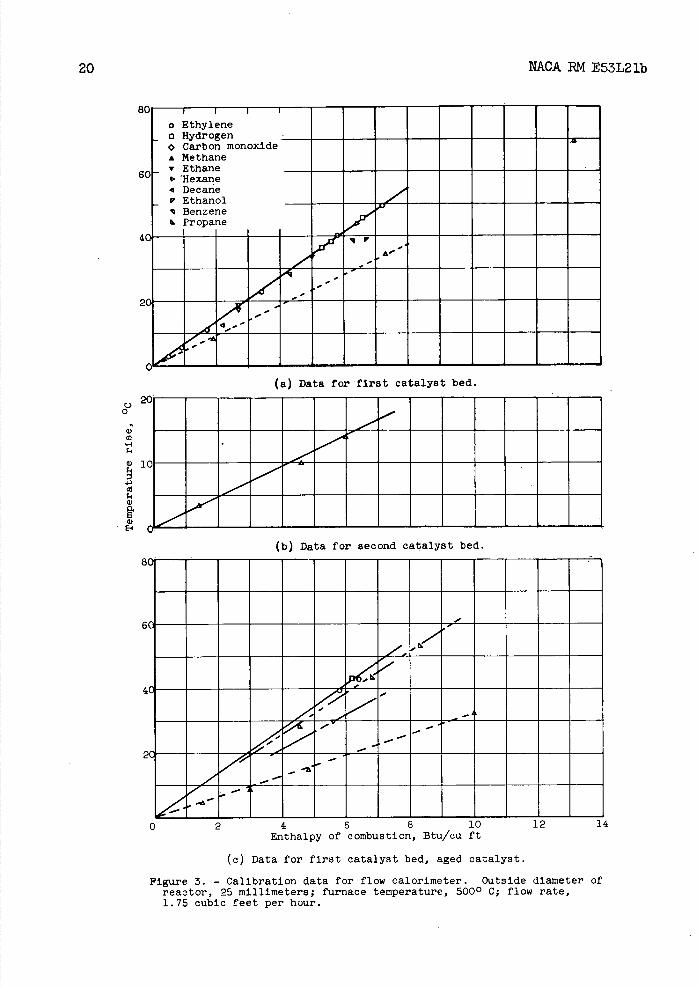
The relations between the measured temperature rise at the first catalyst bed and enthalpy of combustion are shown in figure 3(a) for nine
6 NACA RM E53L21b
combustibles including hexane, d.ecane, benzene, ethanol, and the five representative compounds. The range of enthalpy is that expected of normal turbojet exhaust-gas samples. All points for hydrogen, carbon monoxide, ethylene, and ethane fall along the same straight line passing through the origin. As hydrogen and carbon monoxide are easily oxidized by the catalyst used, even at much lower temperatures, and as no temper-ature rise was observed at the second catalyst bed, complete oxidation can be assumed; and the straight line in figure 3(a) represents the maxi-mum-temperature rise attainable with this calorimeter. Thus, a measure of the oxidation efficiency of the catalyst can be determined for diffi-cultly oxidized gases from the ratio of the temperature rise obtained with such a mixture of known enthalpy to that indicated by the solid line of figure 3(a) for the same enthalpy.
The slope of the solid line in figure 3(a) (calibration line) is approximately 25 percent of the slope of the theoretical line for ideal, adiabatic combustion. Although high heat loss from the reaction zone is thus indicated, the condition is not serious, since the method is empirical and the temperature rises obtainable with mixtures having en-thalpies greater than 1 Btu per cubic foot are sufficiently large for accurate measurement.
With a straight-line relation established, one experimental point for any one of the easily oxidized gases and the origin can be used to establish the calibration line. For this purpose, the standard. ethylene-air mixture with an enthalpy of 5.8 Btu per cubic foot was used to check the calibration line prior to each sample rim.
Inspection of figure 3(a) shows that one of three benzene points, the single points for both ethanol and decane, and the three methane points all fall below the calibration line. Inaccuracies in the prepa-ration of the fuel-air mixtures may account for the benzene and decane deviations. This is especially likely in the case of the decane mixture, which was prepared by saturating air with decane at 00 C and was intro-duced directly into the calorimeter. Failure to attain equilibrium vapor pressure by as little as 0.02 millimeter would account for the deviation of this point. The ethanol-air mixture may have undergone pre-oxidation ahead of the catalyst since the maximum-temperature lo-cation was observed 18 millimeters upstream of that for other combusti-bles. In any case, failure to reach the calibration-line temperature rise with these fuels is of little practical significance, since the concentrations of these and similar types of compounds in exhaust gases are likely to be very small and the calorimeter does indicate their concentration to within 20 percent of the true value.
The incomplete oxidation indicated for methane in the first cat-alyst stage is important since this compound is likely to be present in significant concentrations in exhaust gases. Therefore, special
NACA RM E53L21b
7
provision had to be made to determine completely the enthalpy due to this compound. It was concluded on the basis of figure 3(a) that methane would be the only combustible remaining after passage through the first catalyst bed and that, if the second catalyst bed were empirically cali-brated for methane alone, complete oxidation at this stage would not be necessary. Methane calibration of the second catalyst bed is shown in figure 3(b). The temperature rise was measured with the movable thermo-couple; and the enthalpy of the methane-air mixture, after it passed through the first catalyst bed, was calculated from the following equation:
h2 = h1 (l - E/lOO) (i)
where
h2 enthalpy of combustion after passage through first catalyst bed, Btu/cu ft
h 1 known enthalpy of combustion of prepared methane-air mixture, Btu/cu ft
E catalyst oxidation efficiency at first catalyst bed, percent
The equal slopes of the methane calibration lines in figures 3(a) and 3(b) show equal catalytic efficiencies, but It should be pointed out that this need not always be true.
Measurement of Exhaust-Gas Enthalpy and Combustion Efficiency
The enthalpy of an exhaust-gas sample is based on the maximum temperature rise at each catalyst bed at thermal equilibrium and at the same furnace temperature and flow rate used for calibration. Enthalpy can be determined either graphically from figures 3(a) and 3(b) or cal-culated from the following equation:
H = Kl T1 + K2T2
(2)
where
H total enthalpy of sample, Btu/cu ft
K1 enthalpy equivalent per degree temperature rise at first catalyst bed, evaluated from calibration line, fig. 3(a)
K2 enthalpy equivalent per degree temperature rise at second cat-alyst bed, evaluated from fig. 3(b)
8 NACA RM E53L21b
AT 1 temperature rise at first catalyst bed, °C
AT2 temperature rise at second catalyst bed, 00
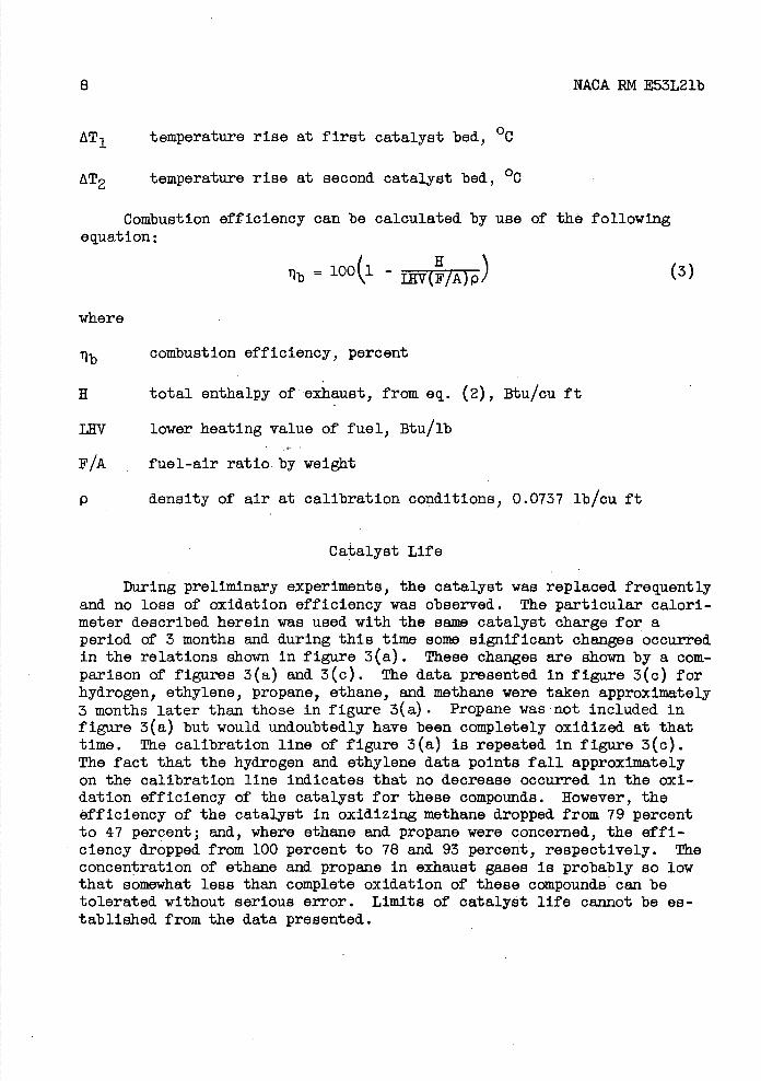
Combustion efficiency can be calculated by use of the following equation:
Ib = 100 - HI(F/A)pJ (3)
where
Tib combustion efficiency, percent
H total enthalpy of exhaust, from eq. (2), Btu/cu ft
LffV lower heating value of fuel, Btu/lb
F/A fuel-air ratio by weight
P density of air at calibration conditions, 0.0737 lb/cu ft
Catalyst Life
During preliminary experiments, the catalyst was replaced frequently and no loss of oxidation efficiency was observed. The particular calori-meter described herein was used with the same catalyst charge for a period of 3 months and during this time some significant changes occurred in the relations shown in figure 3(a). These changes are shown by a com-parison of figures 3(a) and 3(c). The data presented In figure 3(c) for hydrogen, ethylene, propane, ethane, and methane were taken approximately 3 months later than those in figure 3(a). Propane was not Included in figure 3(a) but would undoubtedly have been completely oxidized at that time. The calibration line of figure 3(a) is repeated In figure 3(c). The fact that the hydrogen and ethylene data points fall approximately on the calibration line indicates that no decrease occurred In the oxi-dation efficiency of the catalyst for these compounds. However, the efficiency of the catalyst In oxidizing methane dropped from 79 percent to 47 percent; and, where ethane and propane were concerned, the effi-ciency dropped from 100 percent to 78 and 93 percent, respectively. The concentration of ethane and propane In exhaust gases is probably so low that somewhat less than complete oxidation of these compounds can be tolerated without serious error. Limits of catalyst life cannot be es-tablished from the data presented.
NACA RM E53L21b 9
Methane calibration of the second catalyst bed was repeated and was found to be the seine as in figure 3(b); this indicated a longer catalyst life here, possibly because of the lower temperature. Thus, the decline in oxidation efficiency at the first catalyst bed presents no problem so long as the methane calibration of the second catalyst bed holds. Here, again, limits of catalyst life could not be established and occasional recalibration was necessary.
RESULTS
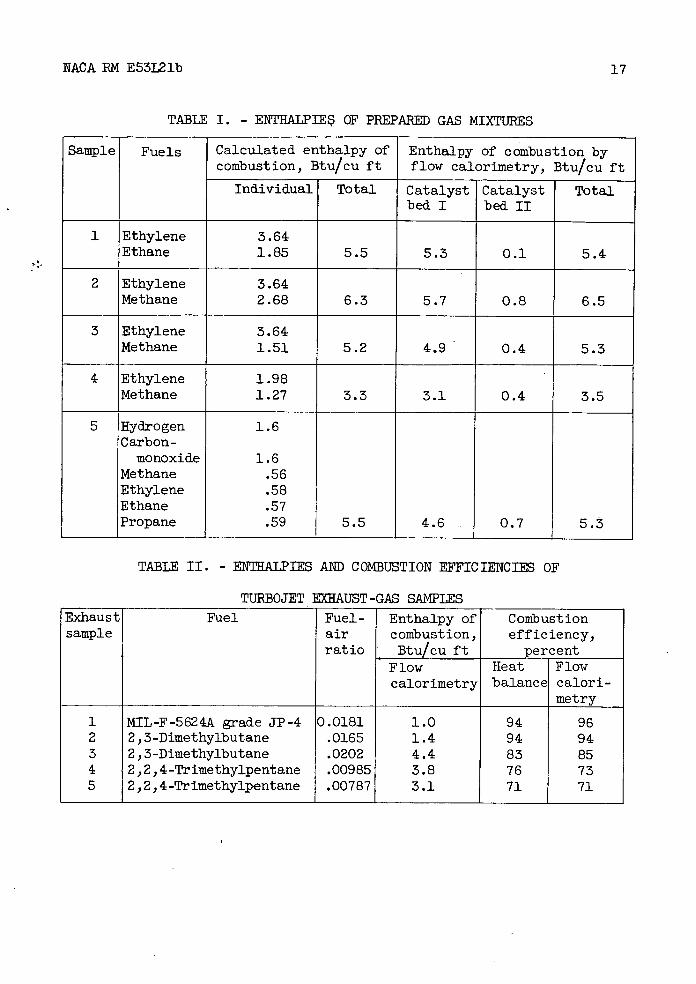
The flow calorimeter was tested with one six-fuel and four two-fuel mixtures. Enthalpies were calculated from partial pressures of the fuels and are accurate to £0.1 Btu per cubic foot. These calculated values are shown in table I together with enthalpies measured by the flow calorimeter. The calculated and experimental values agree within £0.2 Btu per cubic foot, experimental results being high for the ethylene-methane mixtures and low for the thylene-ethane and the six-fuel mixtures. No loss of accuracy was observed for the more complex mixture.
Five samples of turbojet exhaust gas were obtained from two single-combustor testing facilities. Samples 1, 2, and 3 (see table II) were obtained from a single-combustor test installation equipped with three water-cooled pitot—type probes, and samples 4 and 5 were obtained from a similar test installation by means of six uncooled probes. Probes were installed at a position corresponding to the turbine inlet and were arranged radially at centers of annuli of equal areas. Connection to the pump and storage tank was made through a manifold and approximately 6 feet of copper tube. A variety of fuel types, fuel-air ratios, and combustion efficiencies were included in these experiments so that samples might be fairly representative of those to be expected in rou-tine practice. Enthalpy measurements were made within 1/2 hour of sam-pling. In table II are presented combustion efficiencies calculated by the heat-balance method together with enthalpies and combustion efficien-cies measured by flow calorimetry. The heat-balance method is fully des-cribed in reference 4 but, briefly, it involves the use of thermocouples to measure the temperature rise across the combustor which is compared to a theoretical temperature rise. Combustion efficiencies in table II, de-termined by the two methods, compare within 3 percentage units.
DISCUSSION
At present, the development of the flow calorimeter cannot be con-sidered complete, but the results presented heroin show flow calorimetry to be a practical method of measuring residual enthalpy of combustion of exhaust gases and estimating combustion efficiency. The calorimeter is
10
NACA RN E53L21b
portable and simple to operate and can be connected directly to the sampling-probe line; thus, the need for sampling vessels is eliminated. The only service required is a 110-volt electrical outlet for the fur-nace and the diaphragm-pump motor.
Accuracy of enthalpy measurements made with the flow calorimeter can be estimated from the possible errors in measurement of the quan-tities in equation (2). Errors in AT, and AT 2 were small and have
been neglected. Therefore, the relative error in H will be about equal to that in K1 or K2 . K1 was evaluated from the calibration
(solid) line in figure 3(a) and its accuracy depends upon errors in the enthalpy of prepared fuel-air mixtures (0.1 Btu/cu ft) and the repro-ducibility of the calorimeter. From the average of 10 runs made over a period of 3 months with the standard ethylene-air mixture (5.8 Btu/cu ft) and the same reactor and catalyst charge, the reproducibility of results was found to be ±1.00 C. These inaccuracies indicate a probable maximum error in the determination of the residual enthalpy of combustion of ex-haust gases of about ±0.2 Btu per cubic foot. Accuracies of this order are shown in the results listed in table I and indicate the average potential accuracy of enthalpy measurements made with the flow calori-meter when the enthalpy content is of the order of 5 Btu per cubic foot. Experience with very lean mixtures has indicated that the calorimeter Is sensitive to about 0.1 Btu per cubic foot, and it is probable that an accuracy somewhat better than 0.2 Btu per cubic foot can be obtained with these very lean mixtures.
The results presented in table II do not necessarily Indicate the accuracy of combustion-efficiency measurements by either the heat-balance or the flow-calorimetric methods, although an effort was made to maintain good sampling conditions in these cases. Table II provides a comparison of the two methods only; a maximum difference of 3 percent combustion efficiency is considered good. However a comparison of the equations used to calculate combustion efficiency by the heat-balance and flow- calorimetric methods shows that the calorimetric method is inherently more accurate at high combustion-efficiency levels. In heat-balance methods the following equation is used
bLffVx F/Ax p(4)
where
H* enthalpy rise determined from difference between average inlet and average outlet temperatures, measured by thermocouples, Btu/cu ft
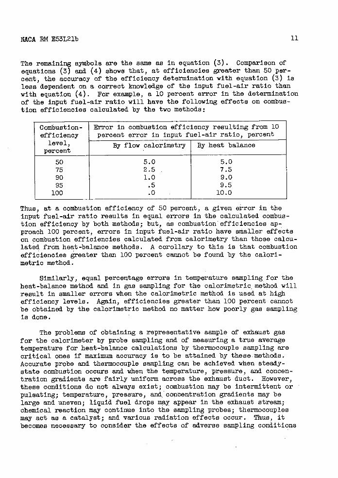
NCA RM E53L21b 11
The remaining symbols are the same as in equation (3). Comparison of equations (3) and (4) shows that, at efficiencies greater than 50 per-cent, the accuracy of the efficiency determination with equation (3) is less dependent on a correct knowledge of the input fuel-air ratio than with equation (4). For example, a 10 percent error in the determination of the Input fuel-air ratio will have the following effects on combus-tion efficiencies calculated by the two methods:
Combustion- efficiency
level,
Error in combustion efficiency resulting from 10 percent error In input fuel-air ratio, percent
By flow calorimetry By heat balance percent
50 5.0 5.0 75 2.5 7.5 90 1.0 9.0 95 .5 9.5
100 .0 10.0
Thus, at a combustion efficiency of 50 percent, a given error in the input fuel-air ratio results in equal errors In the calculated combus-tion efficiency by both methods; but, as combustion efficiencies ap-proach 100 percent, errors in input fuel-air ratio have smaller effects on combustion efficiencies calculated from calorimetry than those calcu-lated from heat-balance methods. A corollary to this Is that combustion efficiencies greater than 100 percent cannot be found by the calori-metric method.
Similarly, equal percentage errors in temperature sampling for the heat-balance method and In gas sampling for the calorimetric method will result in smaller errors when the calorimetric method is used at high efficiency levels. Again, efficiencies greater than 100 percent cannot be obtained by the calorimetric method no matter how poorly gas sampling Is done.
The problems of obtaining a representative sample of exhaust gas for the calorimeter by probe sampling and of measuring a true average temperature for heat-balance calculations by thermocouple sampling are critical ones if maximum accuracy is to be attained by these.methods. Accurate probe and thermocouple sampling can be achieved when steady-state combustion occurs and when the temperature, pressure, and concen-tration gradients are fairly uniform across the exhaust duct. However, these conditions do not always exist; combustion may be intermittent or pulsating; temperature, pressure, and concentration gradients may be large and uneven; liquid fuel drops may appear in the exhaust stream; chemical reaction may continue Into the sampling probes; thermocouples may act as a catalyst; and various radiation effects occur. Thus, it becomes necessary to consider the effects of adverse sampling conditions
12
NACA RM E53L21b
In all applications of the two methods. In this respect, thermocouples have an advantage over gas-sampling probes In that a larger number of thermocouples can be Installed in a given exhaust duct.
Although the flow calorimeter Is not as suitable for large scale, routine measurements as are thermocouples, the calorimetric method., be-cause of its greater inherent accuracy, would be valuable for verifying near-100-percent efficiency data obtained by other methods. Also, the flow calorimeter may be used at high combustor temperatures where the life of ordinary thermocouples Is too short for practical use and precious-metal thermocouples have not been satisfactory.
Aside from sampling difficulties, the principal disadvantages of the flow calorimeter are the time lag of about 4 minutes to establish thermal equilibrium and the uncertain and possibly short life of the catalyst. These problems require further investigation.
SUMMARY OF RESULTS AND CONCLUSIONS
Flow calorimetry was shown to be a feasible method of determining the combustion efficiency of ram-jet and turbojet combustors by measure-ment of the residual enthalpy of combustion of the exhaust gases. A suitable flow calorimeter, its calibration, and Its operation were de-scribed. Briefly, the calorimeter catalytically oxidizes the combustible constituents of exhaust-gas samples, and the resultant temperature rise is measured. This temperature rise was related to the residual enthalpy of combustion of the sample by previous calibration of the calorimeter, and the combustion efficiency was calculated from measured residual en-thalpy of combustion of the exhaust gas and the combustor Input enthalpy. The catalyst used was capable of completely oxidizing all the combus-tibles except methane, and a second oxidation stage was provided to determine completely enthalpy due to this compound.
Accuracy of enthalpy measurements was shown to be ±0.2 Btu per cubic foot with prepared fuel-air mixtures. Combustion efficiencies measured by flow calorimetry and the heat-balance method compared within 3 per-centage units. Although the flow calorimeter Is not as suitable for routine measurements as thermocouples, the method. Is fundamentally more accurate at high combustion-efficiency levels; and it could be used to verify near-100-percent efficiency data obtained by other methods. More important, the method may be used at high combustor temperatures where thermocouple life Is too short for practical use.
NACA EM E53L21b
13
Development of the flow calorimeter cannot be considered complete. Problems requiring further Investigation are the time lag required to attain thermal equilibrium, the need for two-stage oxidation of methane, and the uncertain and possibly short catalyst life.
Lewis Flight Propulsion Laboratory National Advisory Committee for Aeronautics
Cleveland, Ohio, December 21, 1953
14 NACA RN E53L21b
APPENDIX - DEVELOPMENT OF FLOW CALOBIMTER
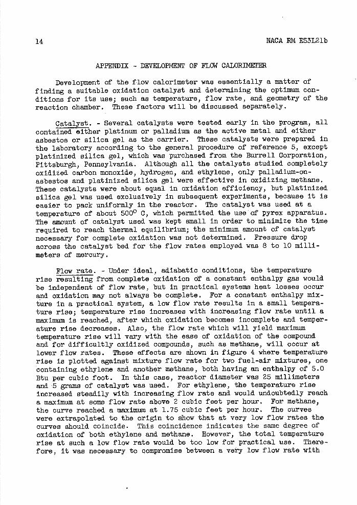
Development of the flow calorimeter was essentially a matter of finding a suitable oxidation catalyst and determining the optimum con-ditions for its use; such as temperature, flow rate, and geometry of the reaction chamber. These factors will be discussed separately.
Catalyst. - Several catalysts were tested early in the program, all contained either platinum or palladium as the active metal and either asbestos or silica gel as the carrier. These catalysts were prepared in the laboratory according to the general procedure of reference 5, except platinized silica gel, which was purchased from the Burrell Corporation, Pittsburgh, Pennsylvania. Although all the catalysts studied completely oxidized carbon monoxide, hydrogen, and ethylene, only palladium-on-asbestos and platinized silica gel were effective in oxidizing methane. These catalysts were about equal in oxidation efficiency, but platinized silica gel was used exclusively in subsequent experiments, because it is easier to pack uniformly in the reactor. The catalyst was used at a temperature of about 5000 C, which permitted the use of pyrex apparatus. The amount of catalyst used was kept small in order to minimize the time required to reach thermal equilibrium; the minimum amount of catalyst necessary for complete oxidation was not determined. Pressure drop across the catalyst bed for the flow rates employed was 8 to 10 milli-meters of mercury.
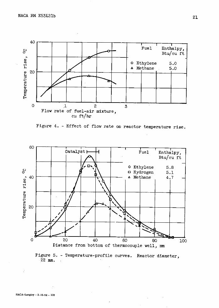
Flow rate. - Under ideal, adiabatic conditions, the temperature rise resulting from complete oxidation of a constant enthalpy gas would be independent of flow rate, but in practical systems heat losses occur and oxidation may not always be complete. For a constant enthalpy mix-ture in a practical system, a low flow rate results in a small tempera-ture rise; temperature rise increases with increasing flow rate until a maximum is reached, after which oxidation becomes incomplete and temper-ature rise decreases. Also, the flow rate which will yield maximum temperature rise will vary with the ease of oxidation of the compound and for difficultly oxidized compounds, such as methane, will occur at lower flow rates. These effects are shown in figure 4 where temperature rise is plotted, against mixture flow rate for two fuel-air mixtures, one containing ethylene and another methane, both having an enthalpy of 5.0 Btu per cubic foot. In this case, reactor diameter was 25 millimeters and 5 grains of catalyst was used. For ethylene, the temperature rise increased steadily with increasing flow rate and would undoubtedly reach a maximum at some flow rate above 2 cubic feet per hour. For methane, the curve reached a maximum at 1.75 cubic feet per hour. The curves were extrapolated to the origin to show that at very low flow rates the curves should. coincide. This coincidence indicates the same degree of oxidation of both ethylene and methane. However, the total temperature rise at such a low flow rate would be too low for practical use. There-fore, it was necessary to compromise between a very low flow rate with
NACA RM E53L21b 15
complete oxidation but very little temperature rise and a high flow rate with partial oxidation but higher temperature rise. The flow rate chosen was 1.75 cubic feet per hour, at which maximum temperature rise was ob-tained with methane.
Reaction chamber. - The important dimension of the reaction chamber was its diameter, which determined linear flow velocity through the cat-alyst bed for a given volume flow rate. In order to explain the effect of reactor diameter, temperature-profile curves are presented in figure 5 for three fuel-air mixtures - hydrogen, ethylene, and methane. The re-actor diameter was 22 millimeters and the position of the catalyst bed is shown. It can be seen that maximum temperature rise occurred at different levels within the catalyst bed and in the order of the oxid.iza-bility of the fuels. Maximum of the methane curve occurred approximately 8 millimeters above the level at which maximum temperature rise occurred for hydrogen while the maximum for ethylene occurred between these two extremes. In order to obtain maximum temperature rise with a mixture of these compounds, oxidation of all compounds must occur at the same level. When the same amount of catalyst was used with a 32 millimeter outside diameter reactor (which reduced the linear flow velocity through the catalyst) the maximum for both the methane and hydrogen curves occurred at the same level. However, the magnitude of the temperature rises ob-tained was considerably reduced. When a 13-millimeter-outside-diameter reactor was used, the magnitude of the temperature rises Increased, but the maximums occurred at levels 28 millimeters apart. In a compromise, a 25-millimeter-outside-diameter reactor was selected and, the maximum distance between oxidation levels was found to be 4 millimeters.
It will be noticed in figure 5 that considerable temperature rise occurred ahead of the catalyst. This Is believed to be due to heat con-duction along the thermocouple well rather than oxidation ahead of the catalyst.
From these preliminary investigations, it was decided to use plati-nized silica gel at 5000 C as the catalyst, a 25-millimeter-outside-diameter reaction chamber, and a volume flow rate of 1.75 cubic feet per hour.
1. Macfarlane, J. J.: The Application of Chemical Analysis to the Investigation of Gas Turbine Combustion Problems. Proc. mt. Cong. Pure and Appl. Chem., vol. 4, 1947, pp. 533-542.
2. Lloyd, Peter: Determination of Gas-Turbine Combustion-Chamber Effi-ciency by Chemical Means. Trans. A.S.M.E., vol. 70, no. 4, May 1948, pp. 335-341.
16
NACA RN E53L21b
3. Ruegg, F. W., and Halpern, C.: Gravimetric Analysis of Exhaust Gas from Gas Turbine Combustion Chambers. Jour. Res. Nat. Bur. Standards, vol. 45, no. 2 1 Aug. 1950, pp. 113-121.
4. Olson, Walter T., and Berrard.o, Everett: Temperature Measurements and. Combustion Efficiency in Combustors for Gas-Turbine Engines. Trans. A.S.M.E., vol. 70, no. 4, May 1948, PP. 329-333; discussion,
PP . 333-334.
5. Platanov, M. S., and Nelaasova, Olga V.: Selective Combustion of Hydrogen, Carbon Monoxide, and Methane by Means of Palladium Catalyzer. Chem. Abs., vol. 31, no. 1, Jan. 10, 1937, p. 69. (Abs. from Za. f. Analytische Chem., Bd. 106, 1936, pp. 416-427.)
NACA RM E53L21'b
17
TABLE I. - ENTHALPIES OF PREPARED GAB MIXTURES
Sample Fuels Calculated enthalpy of combustion, Btu/cu ft
Enthalpy of combustion by flow calorimetry, Btu/cu ft
Individual Total Catalyst Catalyst Total bed I bed II
1 Ethylene 3.64 Ethane 1.85 5.5 5.3 0.1 5.4
2 Ethylene 3.64 Methane 2.68 6.3 5.7 0.8 6.5
3 Ethylene 3.64 Methane 1.51 5.2 4.9 0.4 5.3
4 Ethylene 1.98 Methane 1.27 3.3 3.1 0.4 3.5
5 Hydrogen 1.6 Carbon-monoxide 1.6
Methane .56 Ethylene .58 Ethane .57 Propane .59 5.5 4.6 0.7 5.3
TABLE II. - ENTHALPIES AND COMBUSTION EFFICIENCIES OF
TURBOJET EXHAUST-GAS SAMPLES Exhaust sample
Fuel Fuel- air ratio
Enthalpy of combustion, Btu/cu ft
- Combustion efficiency,
percent Flow Heat Flow calorimetry balance calori-
______ metry
1 MIL-F-5624A grade JP-4 0.0181 1.0 94 96 2 2,3-Dimethylbutane .0165 1.4 94 94 3 2,3-Ditnethylbutane .0202 4.4 83 85 4 2,2,4-Trimethylpentane .00985 3.8 76 73 5 2,2,4-Trimethylpentane .00787 3.1 71 71
-1 I -P
-po
CH
- 0 4a r-4 cqo p1 -P
r-1 LOi
4,
w -p -P liD
r-lr1 r4 0
r4Q) q1
C) -Pgj Po g r1 Pi 4-2
w
,-1ra
-i -P 4-' C) ,-4 al -4
P4 i4 0 '-1 I -4 4
I -4 0 Pi c
(I)r1 CQ . r4
E-1=o
C.)
.4.,
ca
cEj
18 NACA RM E53L21b
NACA PM E53L21b
19
T 270 rim
14 mm
80 mm
ml12 mm
250 mm
I 0
per
iermocouple well, 2-mm O.D. ;ainless-steel tube
Lrrnace, 3-inch O.D. aluminum
cond catalyst bed, 5 g platinized silica gel
talyst support, stainless-eel cloth, 50x40 mesh
actor, 25-mm O.D. pyrex
rst catalyst bed, 3 g platinized silica gel
balyst support, stainless-sel cloth, 50X40 mesh
Ll for furnace thermocouple
: Electric heating element
Glass wool
Aluminum
Magnesium oxide and asbestos
CD-3347
40 mm
Figure 2. - Cross sectional view of flow calorimeter.
I I I I
o Ethylene
-
- a Hydrogen _.o Carbon monoxide £ Methane vEthane
-
Hexane i Decane
- rEthanol --
-
Benzene Propane
,/ -----
8C
6(
4(
2(
o- -
(a) Data for first catalyst bed.
20 NACA RM E53L21b
(b) Data for second catalyst bed.
7 --- - 4(---------------------ol (7 - --
- — — — 2(--
L)Enthalpy of combustion, Btu/cu ft
(c) Data for first catalyst bed, aged catalyst.
Figure 3. - Calibration data for flow calorimeter. Outside diameter of reactor, 25 millimeters; furnace temperature, 5000 C; flow rate, 1.75 cubic feet per hour.
0 0
cd
-1
0. C S
E-4
NACA RM E53L21b 21
0 0
a)
•r
a) 20
4) ci
a)
ft ci)
E-
-
I I Fuel Enthalpy,
Btu/cu ft
0 Ethylene 5.0 4 Methane 5.0
0 .1 2 3 Flow rate of fuel-air mixture,
cu ft/hr
Figure 4. - Effect of flow rate on reactor temperature rise.
60
Ló
- 40 a) ci
a)
4) ci
ci) 20 ft a) El
CatalystI I
Fuel Enthalpy,
X Btu/cu ft
0 Ethylene 5.8 0 Hydrogen 5.1
I 4 Methane 4.7 - ____
/
,V
0 20 40 60 80 100 Distance from bottom of thermocouple well, rum
Figure 5. - Temperature-profile curves. Reactor diameter, 22 mm.
NACA-Langley - 3-10-54 - 330