Embed Size (px)
Citation preview
Confidential Slide 1
Moldflow Analysis Report
Description: 3 D dimension of this part is 160.58mmX86.63mmX53.49 mm
Volume of this part is 35.22 cm^3
To be sure that the design reasonable and injection molding feasible, we used Moldflow
MPI6.1 to analyze
Confidential Slide 2
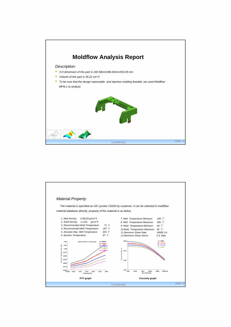
Material Property:
The material is specified as GE cycolac C6200 by customer, it can be selected in moldflow
material database directly, property of the material is as below.
1. Melt Density 0.98129 g/cm^3
2. Solid Density 1.1161 g/cm^3
3. Recommended Mold Temperature 71℃
4. Recommended Melt Temperature 267℃
5. Absolute Max. Melt Temperature 325℃
6. Ejection Temperature 87 ℃
7. Melt Temperature Minimum 248 ℃8. Melt Temperature Maximum 285 ℃9. Mold Temperature Minimum 60 ℃10.Mold Temperature Maximum 82 ℃11.Maximum Shear Rate 40000 1/s12.Maximum Shear Stress 0.4 Mpa
PVT graph Viscosity graph
Confidential Slide 3
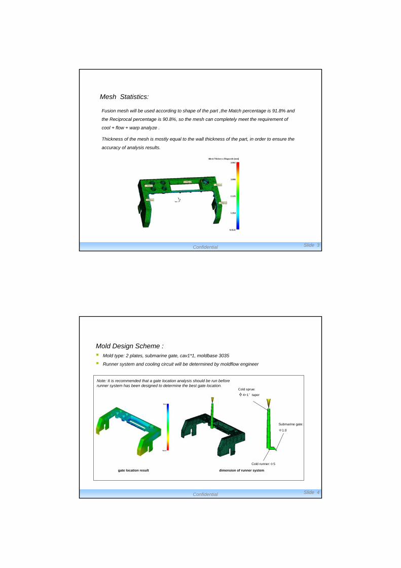
Mesh Statistics:
Fusion mesh will be used according to shape of the part ,the Match percentage is 91.8% and
the Reciprocal percentage is 90.8%, so the mesh can completely meet the requirement of
cool + flow + warp analyze .
Thickness of the mesh is mostly equal to the wall thickness of the part, in order to ensure the
accuracy of analysis results.
Confidential Slide 4
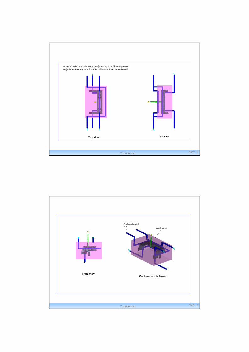
Mold Design Scheme : Mold type: 2 plates, submarine gate, cav1*1, moldbase 3035
Runner system and cooling circuit will be determined by moldflow engineer
Note: It is recommended that a gate location analysis should be run before runner system has been designed to determine the best gate location.
gate location result dimension of runner system
Cold runner:φ5
Cold sprue:
φ4+1°taper
Submarine gate:
Φ1.0
Confidential Slide 5
Note: Cooling circuits were designed by moldflow engineer , only for reference, and it will be different from actual mold
Top view Left view
Confidential Slide 6
Front viewCooling circuits layout
Work piece
Cooling channel Φ8
Confidential Slide 7
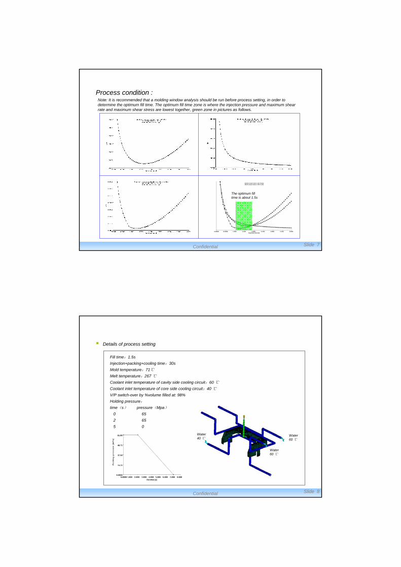
Process condition :
The optimum fill time is about 1.5s
Note: It is recommended that a molding window analysis should be run before process setting, in order to determine the optimum fill time. The optimum fill time zone is where the injection pressure and maximum shear rate and maximum shear stress are lowest together, green zone in pictures as follows.
Confidential Slide 8
Details of process setting
Fill time:1.5s
Injection+packing+cooling time:30s
Mold temperature:71℃
Melt temperature:267 ℃
Coolant inlet temperature of cavity side cooling circuit:60 ℃
Coolant inlet temperature of core side cooling circuit:40 ℃
V/P switch-over by %volume filled at: 98%
Holding pressure:
time(s) pressure(Mpa)
0 65
2 65
5 0
Water 40 ℃
Water 60 ℃
Water 60 ℃
Confidential Slide 9
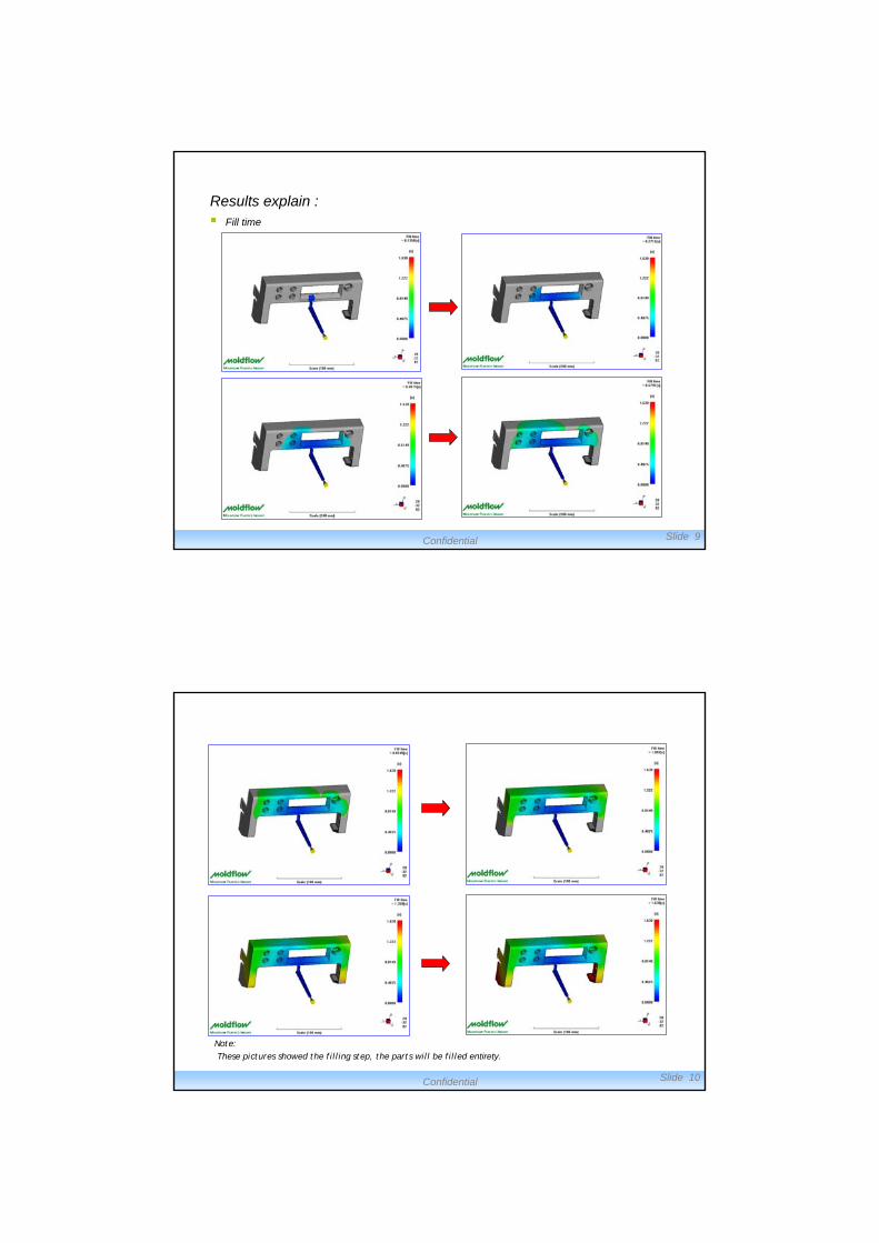
Results explain : Fill time
Confidential Slide 10
Note:These pictures showed the filling step, the parts will be filled entirety.
Confidential Slide 11
AnimationAnimation
Confidential Slide 12
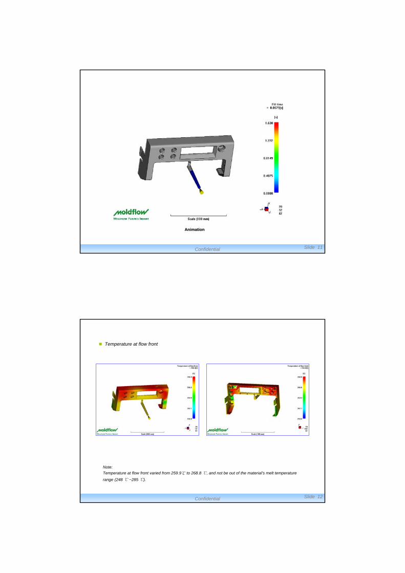
Temperature at flow front
Note:
Temperature at flow front varied from 259.9℃ to 268.8 ℃, and not be out of the material’s melt temperature
range (248 ℃ ~285 ℃).
Confidential Slide 13
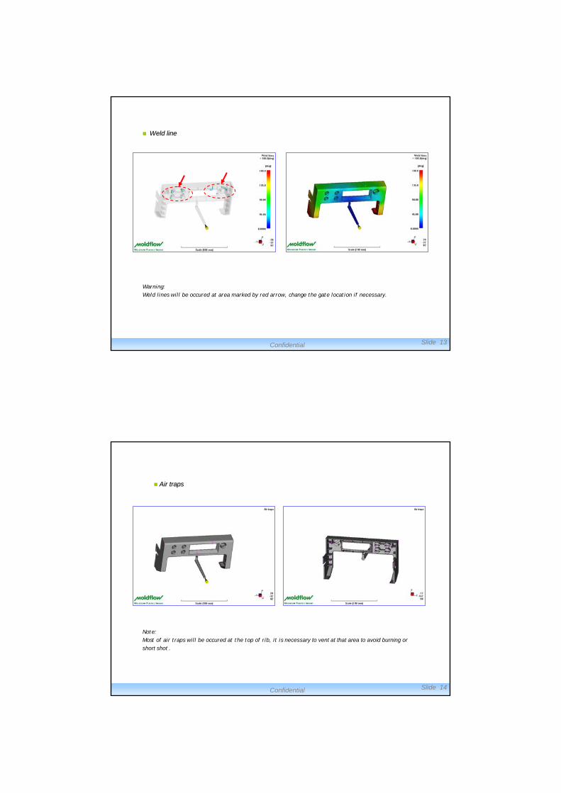
Weld lineWeld line
Warning:Weld lines will be occured at area marked by red arrow, change the gate location if necessary.
Confidential Slide 14
Note:Most of air traps will be occured at the top of rib, it is necessary to vent at that area to avoid burning or
short shot .
Air trapsAir traps
Confidential Slide 15
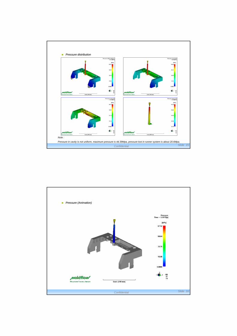
Pressure distributionPressure distribution
Note :
Pressure in cavity is not uniform, maximum pressure is 44.39Mpa, pressure lost in runner system is about 20.6Mpa.
Confidential Slide 16
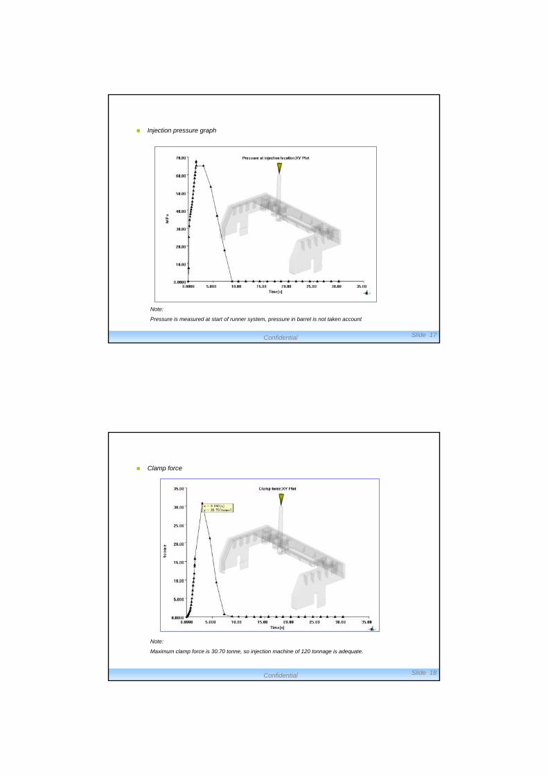
Pressure Pressure (Animation)(Animation)
Confidential Slide 17
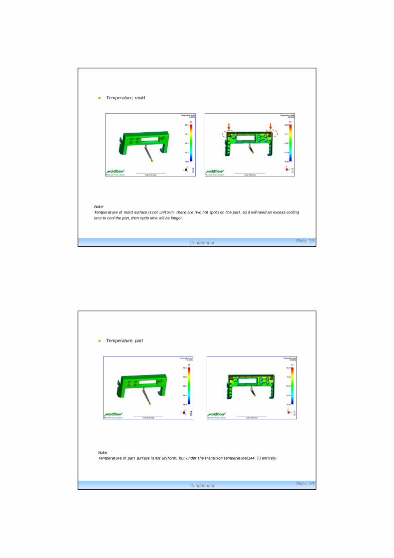
Injection pressure graph
Note:
Pressure is measured at start of runner system, pressure in barrel is not taken account
Confidential Slide 18
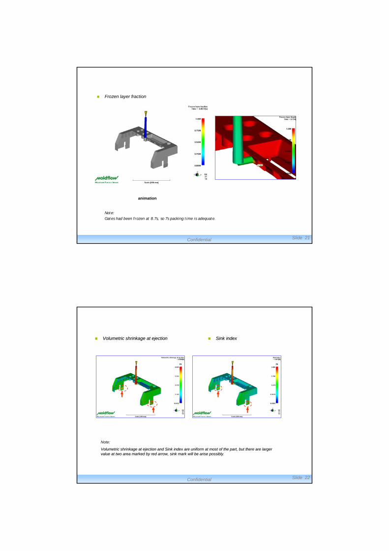
Clamp force
Note:
Maximum clamp force is 30.70 tonne, so injection machine of 120 tonnage is adequate.
Confidential Slide 19
Temperature, mold
Note:Temperature of mold surface is not uniform, there are two hot spots on the part, so it will need an excess cooling
time to cool the part, then cycle time will be longer.
Confidential Slide 20
Temperature, part
Note:Temperature of part surface is not uniform, but under the transition temperature(144 ℃) entirely.
Confidential Slide 21
Frozen layer fraction
Note:Gates had been frozen at 8.7s, so 7s packing time is adequate.
animation
Confidential Slide 22
Volumetric shrinkage at ejectionVolumetric shrinkage at ejection Sink indexSink index
Note:
Volumetric shrinkage at ejection and Sink index are uniform at mVolumetric shrinkage at ejection and Sink index are uniform at most of the part, but there are larger ost of the part, but there are larger value at two area marked by red arrow, sink mark will be arise pvalue at two area marked by red arrow, sink mark will be arise possibly. ossibly.
Confidential Slide 23
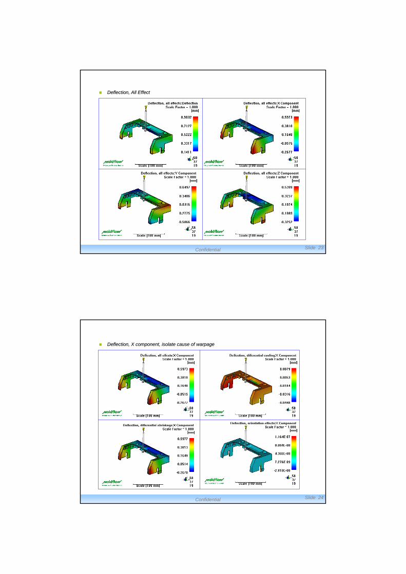
Deflection, All EffectDeflection, All Effect
Confidential Slide 24
Deflection, X component, isolate cause of Deflection, X component, isolate cause of warpagewarpage
Confidential Slide 25
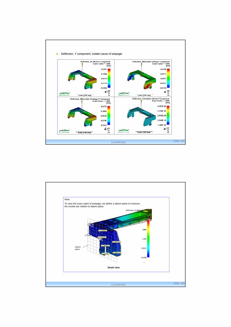
Deflection, Y component, isolate cause of Deflection, Y component, isolate cause of warpagewarpage
Confidential Slide 26
Detail view
Note:
To view the exact value of warpage, we define a datum plane to measure, the results are relative to datum plane.
Datum plane
Confidential Slide 27
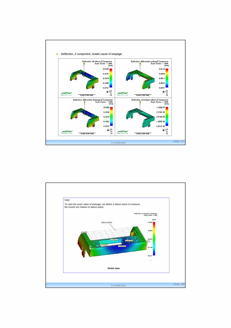
Deflection, Z component, isolate cause of Deflection, Z component, isolate cause of warpagewarpage
Confidential Slide 28
Detail view
Note:
To view the exact value of warpage, we define a datum plane to measure, the results are relative to datum plane.
Datum plane
Confidential Slide 29
Conclusion And Advice:
It is known from the analysis results that:
The part will be full filled easily, and injection machine of 120 tonnage is adequate;
Weld lines will be arised at part surface, this will cause an unexpected influence to
the quality, change the gate location to avoid or improve weld lines if necessary ;
Warpage value is high, Diff Shrinkage are the primary cause of warpage.
Confidential Slide 30
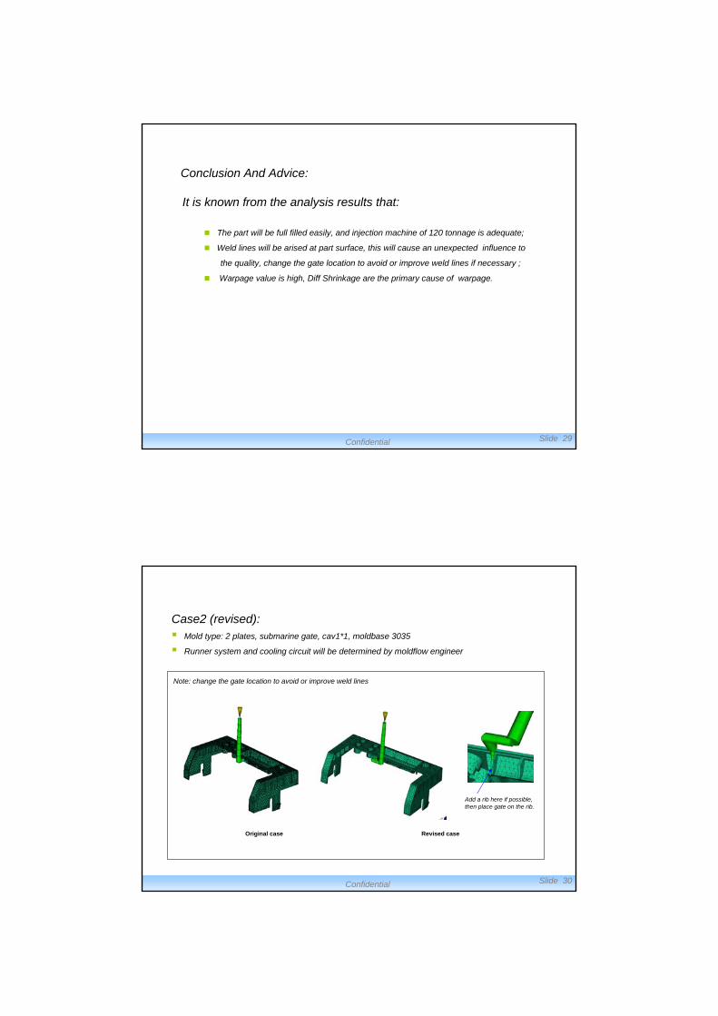
Case2 (revised): Mold type: 2 plates, submarine gate, cav1*1, moldbase 3035
Runner system and cooling circuit will be determined by moldflow engineer
Note: change the gate location to avoid or improve weld lines
Original case Revised case
Add a rib here if possible, then place gate on the rib.
Confidential Slide 31
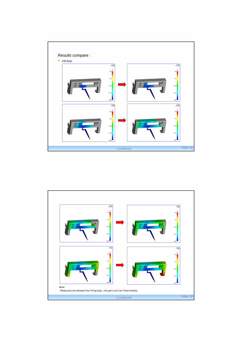
Results compare : Fill time
Confidential Slide 32
Note:These pictures showed the filling step, the parts will be filled entirety.
Confidential Slide 33
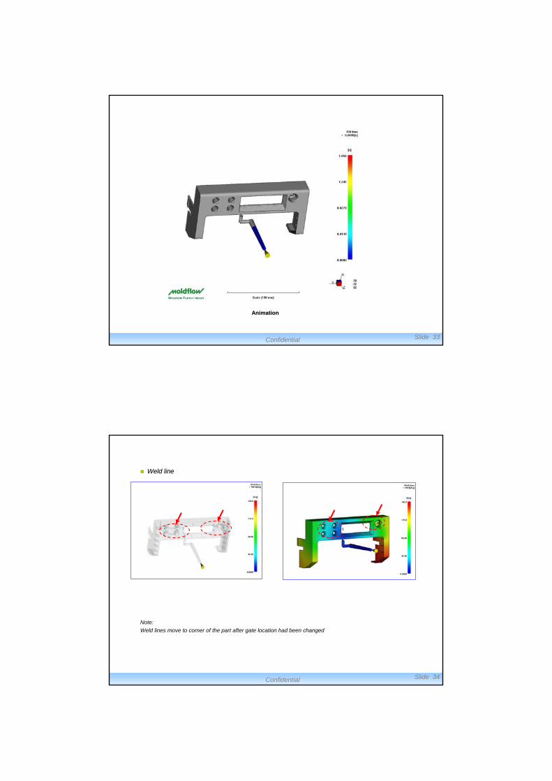
AnimationAnimation
Confidential Slide 34
Weld lineWeld line
Note:
Weld lines move to corner of the part after gate location had been changed
Confidential Slide 35
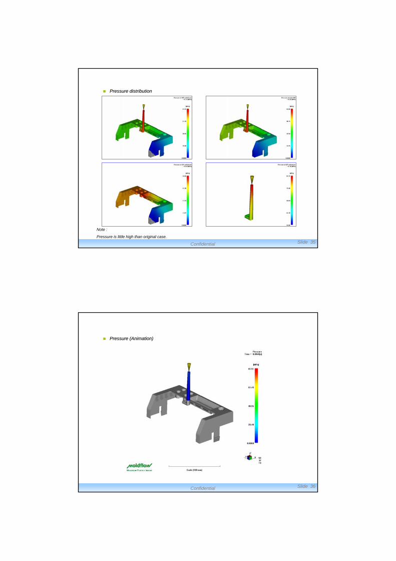
Pressure distributionPressure distribution
Note :
Pressure is little high than original case.
Confidential Slide 36
Pressure Pressure (Animation)(Animation)
Confidential Slide 37
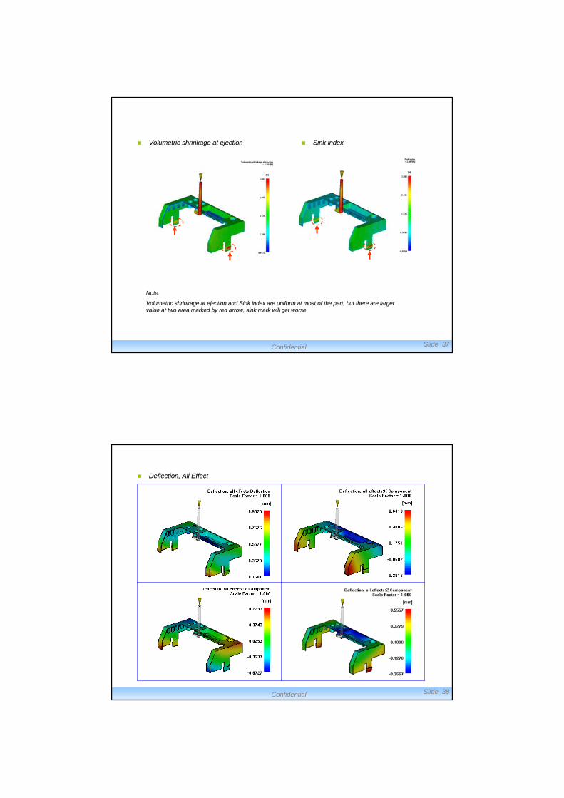
Volumetric shrinkage at ejectionVolumetric shrinkage at ejection Sink indexSink index
Note:
Volumetric shrinkage at ejection and Sink index are uniform at mVolumetric shrinkage at ejection and Sink index are uniform at most of the part, but there are larger ost of the part, but there are larger value at two area marked by red arrow, sink mark will get worse.value at two area marked by red arrow, sink mark will get worse.
Confidential Slide 38
Deflection, All EffectDeflection, All Effect
Confidential Slide 39
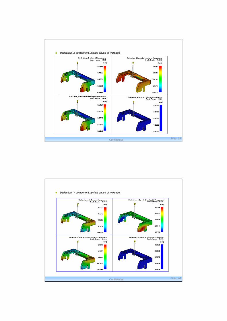
Deflection, X component, isolate cause of Deflection, X component, isolate cause of warpagewarpage
Confidential Slide 40
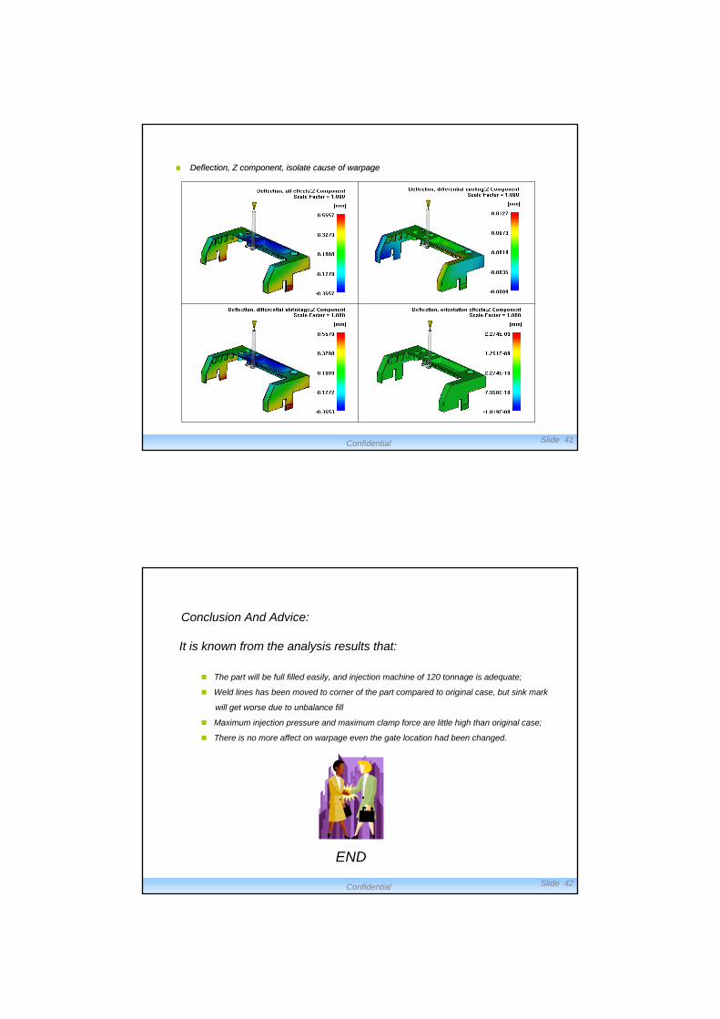
Deflection, Y component, isolate cause of Deflection, Y component, isolate cause of warpagewarpage
Confidential Slide 41
Deflection, Z component, isolate cause of Deflection, Z component, isolate cause of warpagewarpage
Confidential Slide 42
Conclusion And Advice:
END
It is known from the analysis results that:
The part will be full filled easily, and injection machine of 120 tonnage is adequate;
Weld lines has been moved to corner of the part compared to original case, but sink mark
will get worse due to unbalance fill
Maximum injection pressure and maximum clamp force are little high than original case;
There is no more affect on warpage even the gate location had been changed.