Embed Size (px)
Citation preview

1
MTEC PAC300
Photoacoustic Detector
Operating Instructions
January 2017
MTEC Photoacoustics, Inc.
3507 Oakland St.
Ames, IA 50014 USA
Telephone and Fax: 1 515 292 7974
www.mtecpas.com

2
Table of Contents
1. First and Foremost: Three Key Precautions to Protect PAC300 from Damage 1.1 Protecting Microphone during Purging ………………………………............3 1.2 Caution to Avoid Breaking Window ……………………………………………….3 1.3 Protecting Window from Moisture Damage …………………………………..3
2. Unpacking 2.1 Unsealing the Hermetically Sealed Shipping/Storage Case ……………..3
2.2 Packing List …………………………………………………………………………………...3 2.3 Damage Inspection …………………………………………………………………………4
3. PAC300 Description 3.1 Introduction to the PAC300 ………………………………………………………………….4
4. Set-Up Directions
4.1 Insert Rear Lever …………………………………………………………………………….5
4.2 Mounting and Alignment of the PAC300 in the FTIR ……………………..…6
4.3 Electrical Connections …………………………………………………………………….9
4.4 Purge Gas Connections …………………………………………………………………..10
5. Operation
5.1 Preamplifier Gain Control …………………………………………………………..….10
5.2 Rear Lever Operation …………………………………………………………………….11
5.3 Sample Cup Loading ……………………………………………………………………..11
5.4 Sample Cup Insertion …………………………………………………………………..…13
5.5 Purging ………………………………………………………………………………………....14
5.6 FTIR Spectrum Acquisition Parameters ………………………………………..…14
5.7 Test Procedure ……………………………………………………………………………….15
5.8 Acquiring and Normalizing a Sample Spectrum …………………………..…15
5.9 Advanced Methods of Photoacoustic Spectroscopy ……………………...16
5.10 Storage of the PAC30 ……………………………………………………………………16
6. User Adjustments and Servicing
6.1 Setting the Sample and Reference Cup O-ring Seal Compression …..17
6.2 Window Replacement ……………………………………………………………………17
7. Service Assistance
7.1 Returning Units for Factory Servicing ……………………………………………..19
7.2 Foreign Returns ……………………………………………………………………………….19
8. Product Warranty and Disclaimer …………………………………………………………………..….20

3
1. First and Foremost: Three Key Precautions to Protect PAC300 from Damage
1.1 Protecting Microphone during Purging Purging with zero grade helium gas is used to enhance the sensitivity of photoacoustic measurements and to reduce the moisture level in the sample chamber which superimposes a water vapor spectrum on the sample spectrum and also interferes with condensed sample signal generation. However, a too high gas flow rate can easily damage the PAC300’s sensitive microphone. Accidental high flow rates may occur when gas valves are being opened or adjusted. The PAC300 microphone is protected from gas flow surges as long as the rear lever is in the SEAL position. 1.2 Caution to Avoid Breaking Window Do not place samples in the brass sample cup that extend above 1 mm from the top of the cup. Samples that extend above the top of the cup will break the PAC300’s window. 1.3 Protecting Window from Moisture Damage The PAC300’s KBr window is moisture sensitive. The window can be protected from moisture damage by storing the unit in its hermetically sealed case with a 10 g packet of indicating silica gel ( http://silicagelpackets.com/indicating-silica-gel-packets/indicating-silica-gel-packets/10-gram-indicating.html ).
2. Unpacking
2.1 Unsealing the Hermetically Sealed Shipping/Storage Case In cold weather, it is advisable to let the case warm up for 24 hrs. before opening to prevent moisture condensation on the KBr window. 2.2 Packing List All PAC300 photoacoustic accessories include: 1. PAC300 with focusing mirror and KBr window. 2. Black handled sample holder (inserted in PAC300) with brass sample nest, five small and five large removable sample cups, five nest spacers to elevate samples, sample cup fixture and funnel, tweezers and Allen wrench to adjust cup o-ring compression. 3. Carbon reference sample mounted in black handle. 4. Liquid crystal for imaging IR beam position. 5. Helium flow meter. 6. Hermetically sealed shipping/storage case
4
Some accessories may also include one or more of the following: 1. FTIR specific baseplate mounting. 2. Desk-top power supply. 3. Glassy carbon phase reference. 4. FTIR specific connection cable(s). 5. PAC300 elevation adjustment shims. 6. FTIR purge coupling. 7. SH003 and/or SH004 options.
2.3 Damage Inspection
Please examine items for evidence of shipping damage. Report any damage to the carrier and to MTEC for direct purchases or the reseller that shipped the accessory.
3. PAC300 Description 3.1 Introduction to the PAC300
The PAC300 enables direct measurement by photoacoustic detection of optical absorption spectra of solids and semisolids and is primarily used in FTIR spectrometers: http://www.mtecpas.com/Docs/Photoacoustic%20Technology%20Overview.pdf . The detector can be used for a wide range of measurements as described in the applications literature and literature bibliography: http://www.mtecpas.com/applicationslibrary.html , http://www.mtecpas.com/Docs/FTIR%20PAS%20Bibliography%20Draft%205.pdf .
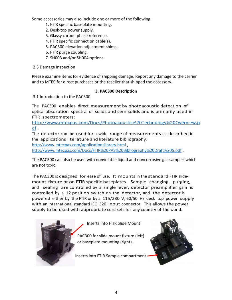
The PAC300 can also be used with nonvolatile liquid and noncorrosive gas samples which are not toxic. The PAC300 is designed for ease of use. It mounts in the standard FTIR slide- mount fixture or on FTIR specific baseplates. Sample changing, purging, and sealing are controlled by a single lever, detector preamplifier gain is controlled by a 12 position switch on the detector, and the detector is powered either by the FTIR or by a 115/230 V, 60/50 Hz desk top power supply with an international standard IEC 320 input connector. This allows the power supply to be used with appropriate cord sets for any country of the world.
Inserts into FTIR Slide Mount
Inserts into FTIR Sample compartment
PAC300 for slide mount fixture (left)
or baseplate mounting (right).

5
4. Set-Up Directions
4.1 Insert Rear Lever
The stainless steel rear lever is packed separately from the PAC300 in the shipping case
and should be inserted into one of the three slots on the back of the PAC300. Use the slot
that allows the lever to rotate most conveniently in your FTIR through the 90 degrees of
rotation necessary to purge and seal the sample. Note that the sample holder can be
inserted from either side of the PAC300 to accommodate both right-to-left and left-to-
right beam directions in different FTIRs.
Purge Inlet
Sample Holder
Rear Lever
FTIR Purge Coupler
Baseplate

6
4.2 Mounting and Alignment of the PAC300 in the FTIR
The PAC300 is either mounted on an FTIR specific baseplate or in the standard sample slide mount found in all FTIRs. Baseplate and slide mounted PAC300s are prealigned and usually will not require the adjustments described below. Alignment can be checked using the infrared heat sensitive liquid crystals supplied with the PAC300.
Lever
Slots
Color Change Indicates FTIR beam focal spot. If the spot is centered in the cup, the PAC300 is aligned.
PAC300 needs to be moved horizontally perpendicular to the IR beam to center the spot in sample cup.
IR Beam
1
2

7
In order to check alignment, place a liquid crystal in the sample cup following the directions in its package. Then block the infrared beam and insert the sample holder with the liquid crystal into the PAC300. Fully open the aperture of the FTIR. Elevate the crystal by moving the rear lever to the CLOSED PURGE position. Remove the beam block, wait several seconds, remove the sample cup, and examine the image pattern before it fades as the temperature falls. The types of images that may be observed are shown above. Image 1 indicates ideal alignment. Image 2 shows side-to-side misalignment. This can be corrected by moving the PAC300 perpendicular to the beam in the direction opposite to the misalignment direction. The side-to-side adjustment can be made as shown below either by loosening the screws on the baseplate and sliding the PAC300 side-to-side or by adjusting the slide plate relative to its mounting yoke.
Image 3 indicates that the PAC300 needs to be raised. The height of baseplate mounted PAC300s can be adjusted with the screws that support the accessory on the baseplate as shown below.
PAC300 needs to be moved vertically to center the spot in sample cup.
3
Shims for height adjustment
Side-to-side adjustment
Side-to-side adjustment
8
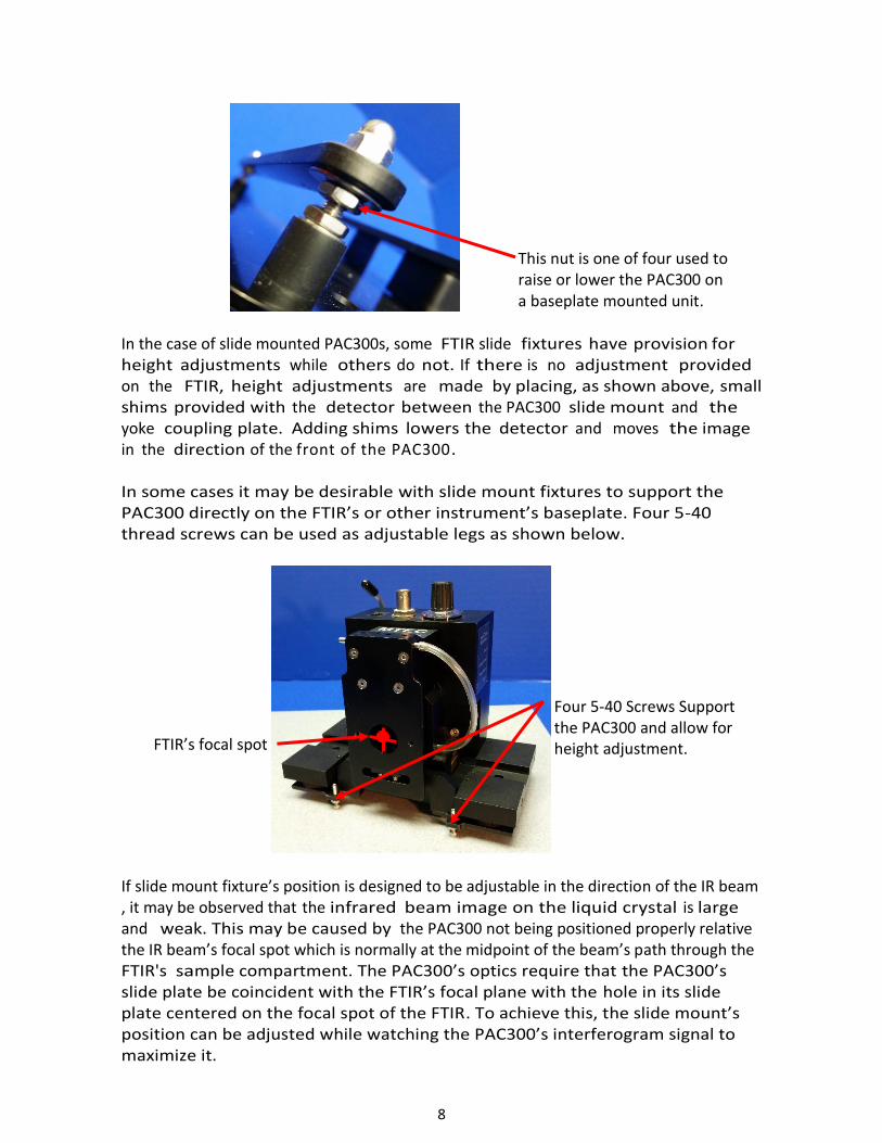
In the case of slide mounted PAC300s, some FTIR slide fixtures have provision for height adjustments while others do not. If there is no adjustment provided on the FTIR, height adjustments are made by placing, as shown above, small shims provided with the detector between the PAC300 slide mount and the yoke coupling plate. Adding shims lowers the detector and moves the image in the direction of the front of the PAC300. In some cases it may be desirable with slide mount fixtures to support the PAC300 directly on the FTIR’s or other instrument’s baseplate. Four 5-40 thread screws can be used as adjustable legs as shown below.
If slide mount fixture’s position is designed to be adjustable in the direction of the IR beam , it may be observed that the infrared beam image on the liquid crystal is large and weak. This may be caused by the PAC300 not being positioned properly relative the IR beam’s focal spot which is normally at the midpoint of the beam’s path through the FTIR's sample compartment. The PAC300’s optics require that the PAC300’s slide plate be coincident with the FTIR’s focal plane with the hole in its slide plate centered on the focal spot of the FTIR. To achieve this, the slide mount’s position can be adjusted while watching the PAC300’s interferogram signal to maximize it.
This nut is one of four used to raise or lower the PAC300 on a baseplate mounted unit.
Four 5-40 Screws Support the PAC300 and allow for height adjustment. FTIR’s focal spot

9
4.3 Electrical Connections The PAC300 is powered either by the FTIR or an MTEC desktop power supply. The power and signal cables are connected to the vibration isolated part of the accessory after first being secured to the stationary part to avoid transmitting mechanical vibrations to the PAC300’s sensitive microphone.
The desktop power supply has +15 and -15 Volt outputs and connects to either 115V 60 Hz or 230V 50 Hz power lines. It has an IEC 320 power cord connector and an RJ9 output connector.
The PAC300’s preamplifier gain is adjustable in 12 steps from 2X to 10,000X to accommodate samples with different thermal properties and FTIR mirror velocities.
Power In
Signal Out
Gain Switch
On-Off switch 120/230 Volt switch

10
4.4 Purge Gas Connections
Purging with Zero Grade Helium increases the signal by a factor of 2 to 3 and helps to exhaust
moisture and CO2 from the sample chamber. A two stage gas regulator valve should be
connected to a helium tank with its output connected to the MTEC flow meter. The
flowmeter output is connected to the inlet of the stationary part of the PAC300. Its outlet is
connected to the vibration isolated sample chamber. Consult Section 5.5 before purging the
PAC300.
5. Operation
5.1 Preamplifier Gain Control
A twelve position switch controls the gain as follows:
step# 1 2 3 4 5 6 7 8 9 10 11 12 gain 2 5 10 20 50 100 200 500 1000 2000 5000 10,000 factor
The gain should be set high enough to give an interferogram amplitude of
several volts but not too high to either cause preamplifier clipping (<20V peak-
to-peak) or to overload the FTIR's A to D converter.
Higher gains are used for higher FTIR mirror velocities because the signal
amplitude decreases as modulation frequency increases. Higher gains are
also used when sample spectra are being acquired relative to carbon
reference background spectra because totally absorbing carbon generates
higher signal amplitudes than partially absorbing samples which usually also
have higher thermal mass.
To Gas Cylinder
Line Pressure
Tank Pressure
Control Flow Rate Only with this Valve
Leave This Valve Always Open
Rear Lever Always In the SEAL Position When Adjusting Valves
Flow Rate 10cc/s or Less

11
5.2 Rear Lever Operation
The rear lever rotates over an angle of 90 degrees to elevate the sample holder
into the detector's sample chamber and to compress the holder’s o-ring to
seal the chamber. The lever also automatically controls the purge valve during
the 90 degree rotation. A detent snap device indexes four rotational positions
over the 90 degree rotation. These are the OPEN, OPEN PURGE, CLOSED
PURGE, and SEAL positions which are shown schematically on the detector's
sides for easy reference during operation.
In the OPEN position the sample holder may be withdrawn or inserted for sample change. In the OPEN PURGE position purge gas flows through the sample chamber and
out the bottom because the sample holder o-ring is not sealed.
In the CLOSED PURGE position purge gas flows past a hole leading to the
sample chamber but not through it. Consequently, purging is slower but
there is no flow over the sample which might blow powders out of the cup.
In the SEAL position the sample chamber is sealed and spectra may be acquired. The purge gas still can flow but is sealed from the sample chamber so the microphone is protected from any surges in the gas flow that might occur when gas valves are being opened, adjusted or closed.
5.3 Sample Cup Loading
The PAC300 is supplied with five small and five large sample cups and five brass spacer inserts. The cups and inserts fit into a brass nest which is attached to the black sample holder handle. The slot in the brass part should be kept oriented perpendicular to the handle length. The o-ring seals the detector when the lever is rotated fully to the SEAL location and must be kept clean.
v
Brass nest rim Sample cups Sample cup elevation spacers

12
To avoid breaking the detector window, do not place anything which extends higher than the rim of the brass nest because when the rear lever is rotated to the SEAL location, the rim is located just below the detector window. Anything extending above the rim will be forced into the window and break it. Samples, depending on size, are placed in the small sample cups or in the large brass cup holder (in the latter case with or without a large sample cup). The brass spacer inserts are used to eliminate excess volume in the sample cup. A higher signal level is consequently obtained because the signal is inversely proportional to the gas volume. The inserts and sample levels in cups should be chosen so that the sample is approximately 1 mm or more below the brass cup holder rim. This distance allows the photoacoustic signal to be generated in the gas without thermal interference by the window above the sample.
Course samples may be placed in cups using tweezers. Fine powders may be loaded with the funnel by first placing cups either directly in the brass nest or in the slotted cup fixture and then placing the funnel in position. An alternative approach is to scoop powders from storage containers with the sample cups held by tweezers and then use the slotted cup fixture to align the tweezers in order to facilitate easy insertion of the cup into the brass cup holder. Be careful not to spill samples onto the o-ring. Only enough sample to cover the bottom of the sample cup is necessary.
Samples (both micro and macro) that evolve H20 vapor should be run with a desiccant in the sample chamber to avoid vapor bands in spectra. Magnesium perchlorate is a very effective desiccant and can often be used safely. This chemical is, however, a strong oxidizing agent and may create a hazard when used in close proximity with certain samples. It is the operator's responsibility to consult and observe appropriate safety information

13
The desiccant is placed in a large sample cup. This cup is inserted into the brass holder, a slotted spacer insert is placed over the desiccant cup, and the slots are aligned to permit gas circulation between the desiccant and sample cups. Finally, the sample is put in a second cup which is inserted above the desiccant cup. Never leave desiccant in the sample cup when the detector is not sealed because a corrosive liquid will form as moisture is collected by the desiccant from the room air. If the detector is stored for an extended time, check the status of the desiccant periodically.
There are several effective approaches in addition to the desiccative cup, which may be used alone or in combination to reduce vapor band interference from a sample. These approaches include vacuum and/or oven drying of samples prior to measurements, reduction of the amount of sample placed in the cup, dry gas purging (zero grade helium), and spectral subtraction. Interference bands may also be present due to residual vapors in the detector from the previous samples, degassing of internal components, or from the storage box. These bands can be readily reduced to an acceptable level by purging. Note that bands due to vapor absorption in the detector are always positive pointing whereas vapor absorption in the spectrometer produces negative pointing bands.
5.4 Sample Cup Insertion
The sample cup can be inserted from either side of the detector since different sides of the detector are accessible with different FTIRs. The sample holder is ready to be slid into place for elevation into the sample chamber and sealing by the rear lever.
Desiccant
Slotted Spacer

14
5.5 Purging
Purging increases the signal level by approximately a factor of 2 to 3 and
reduces moisture in the sample chamber. Care must be taken in purging the
detector, however, to avoid large pressure fluctuations that could damage the
microphone.
Use clean dry helium gas such as "zero grade". Only the primary
pressure regulator valve on the gas cylinder should be used to control the
flow rate as indicated in Section 4.4. If the regulator has a second valve at
the regulator output set this valve to the full open position and leave it so
set. Keep the detector lever in the SEAL position whenever the gas is being
turned on or off and when the flow is being adjusted. These are the times
when pressure surges are most likely to occur and the SEAL position isolates
the microphone.
Use a flow rate of 10-20 cc/s for most samples.
For fine powders reduce the flow to 5 cc/s or lower until the CLOSED
PURGE location is reached to avoid blowing the powder into the
detector.
Ten seconds purge time in each of the purge locations is usually sufficient.
Longer times may be necessary if considerable moisture is present.
Leaving the detector sealed with desiccant under the sample cup for an
extended time during measurements is the best way to remove the last traces
of moisture.
When the detector is initially purged with helium there will be a
gradual decrease in signal amplitude as helium exchanges with air in the
rear volume of the microphone that is connected to the sample chamber by a
fine capillary. This drift will be minimized if helium is kept sealed in the
detector at all times. The signal will also gradually decrease due to diffusion of
helium at the o-ring seals. Signal drift can be eliminated by purging with dry
nitrogen but the signal enhancement of helium is lost.
5.6 FTIR Spectrum Acquisition Parameters For general use, the following are usually appropriate: 1. Minimum mirror velocity that is stable 2. Maximum source aperture
3. Resolution of 8 cm-1 4. Scan number depending on signal-to-noise ratio required

15
5.7 Test Procedure 1. Remove the red protective cap, place the carbon black reference (Fig. 4.11) in the detector and purge the detector, if desired.
CAUTION. Do not allow anything to contact the black absorber surface of the carbon reference. It is easily damaged. Keep the red protective cap on the carbon black reference when not in use. Do not leave the carbon black reference in the detector when a background spectrum is not being acquired. 2. Adjust the detector gain for a peak-to-peak amplitude of several
volts. This will assure t h a t the preamplifier is not clipping (clipping occurs
at approximately 20 volts maximum peak-to-peak) and that the FTIR input is
not overloading.
3. If the PAC300 detector initially does not produce a signal, disconnect and then reconnect the telephone connector on the white cable located next to the detector's gain switch.
4. Acquire two single beam spectra of 8 scans at 8 cm-1 resolution and an OPD mirror velocity of 0.16 cm/s with the MTEC carbon reference. If the FTIR spectrometer does not have an OPD velocity of 0.16 cm/s substitute the closest available. 5. Ratio the two single beam spectra to obtain a 100% line. Peak-to- peak
noise should be 0.4% or less at 2000 cm-1 for most FTIR instruments using a helium purge. The peak-to-peak noise will be found to increase if a higher mirror velocity is used due to the slow time response of photoacoustic signal generation. 5.8 Acquiring and Normalizing a Sample Spectrum 1. Load the sample (see 5.3 and 5.4) and purge (see 5.5) the detector, if desired. 2. Set the detector gain to provide a signal level which is less than or equal to what was used for the carbon black spectrum (see 5.7) and acquire the sample spectrum (see 5.6). 3. Divide the sample spectrum by a carbon black spectrum in order to obtain an absorbance like spectrum of the sample. Some FTIR’s have parameter settings to automatically ratio the sample to reference spectra and display it in photoacoustic units.
Do not touch black surface!

16
Advanced photoacoustic spectroscopic methods utilize both the magnitude and phase of the photoacoustic signal often to investigate depth varying composition in the form of layers or gradients. Glassy carbon is the best phase reference material for such investigations.
5.9 Advanced Methods of Photoacoustic Spectroscopy A general overview of some interesting advanced applications is available here: http://www.mtecpas.com/Docs/Photoacoustic%20Technology%20Overview.pdf. The PAC300 can be used to study samples with depth varying composition in the form of layers and gradients over depth ranges of a few tens of microns. If deeper depths are of interest, MTEC’s MicroLap device (http://www.mtecpas.com/microlap.html) can be used on planar samples. For further information in general see: http://www.mtecpas.com/Docs/MicroLap%20Technology.pdf http://www.mtecpas.com/Docs/MicroLap3.pdf http://www.mtecpas.com/Docs/Introduction%20to%20Photoacoustic%20Spectroscopy%20with%20Step%20Scan%20and%20Constant%20Velocity%20Scan%20FTIR%20Spectrometers.pdf http://www.mtecpas.com/Docs/BCG.pdf http://www.mtecpas.com/Docs/MicroLap1.pdf http://www.mtecpas.com/Docs/MicroLap2.pdf MTEC offers two options with sampling heads for sequential diffuse reflectance, photoacoustic absorbance, and transmittance measurements (Option SH003) and for microsamples in the form of single particles and fibers (Option SH004). For further information see: http://www.mtecpas.com/Docs/MTEC%20Sampling%20Head%20Options.pdf http://www.mtecpas.com/Docs/Prac%20Guide%20to%20FTIR%20Photoacoustic.pdf
5.10 Storage of the PAC300
The PAC300’s KBr window is moisture sensitive. The window can be protected from moisture damage by storing the unit in its hermetically sealed case with a 10 g silica gel desiccant pack with indicator to tell when to change to fresh desiccant: http://silicagelpackets.com/indicating-silica-gel-packets/indicating-silica-gel-packets/10-gram-indicating.html

17
6. User Adjustments and Servicing
6.1 Setting the Sample and Reference Cup O-ring Seal Compression
Two set screws control the compression of the sample cup's o-ring seal. These
screws must be adjusted symmetrically to extend the same distance in order
to avoid cocking the o-ring flange relative to the detector body. When
properly adjusted, the sample holder handle should not be moveable side-
to-side relative to the housing when the rear lever is in the SEAL position.
6.2 Window Replacement
MTEC offers KBR, quartz, CsI, KRS5, and Polyethylene windows. It is
recommended that the detector be returned to MTEC for window
replacement. If the user prefers to replace the window, follow the following
directions.
Disconnect the power and signal cables and the purge line.
Loosen the top set screw, remove the two top slide plate screws and the
attached part which clamps the cables.
No side-to-side motion in rear lever SEAL position

18
Loosen the upper vibration isolator nuts and back off the screws as shown to
allow the detector to be lifted off the lower vibration isolation platform.
The detector’s mirror can now be removed by unscrewing its two attachment
screws to expose the four screws of the window’s o-ring compression plate.
Once these screws are removed using a ball point Allan wrench, the plate can
be lifted off and the window replaced (diameter=18mm, thickness=3mm).
Great care must be taken in tightening the screws to compress the window
o-ring. The screws must be tightened in very small equal angle increments
with a light touch to avoid cracking the window. Carefully tighten the four
compression screws to compress the o-ring while keeping an equal gap on all
sides between the compression plate and the detector housing. The
detector should be reassembled by reversing the disassembly steps.
Remove
Loosen

19
7. Service Assistance
7.1 Returning Units for Factory Servicing
Please contact MTEC for authorization prior to shipping any items for repair. (MTEC email: [email protected], telephone: 1-515-292-7974; telefax: 1-515-292-7974.) All transportation charges and insurance are the customer's responsibility. A purchase order number must be provided before repairs will be made. (See also Section 7 for Product Warranty.) Package the return carefully, securing all parts to prevent damage during transit. Seal the empty sample cup in the detector. Send the entire system including power supply and cables. Shipping address for returns: MTEC Photoacoustics, Inc. 3507 Oakland Street Ames, Iowa 50014 U.S.A.
7.2 Foreign Returns
If possible, ship the package via a courier, such as Federal Express, who will
act on behalf of MTEC as a customs broker. This simplifies the return,
expedites clearance through U.S. Customs, and saves extra freight
forwarder costs to MTEC which are billed back to the customer. Prepay the
air waybill through to Ames, Iowa. Consign to the shipping address above,
and list MTEC's telephone number (515-292-7974). To avoid complications
and delays, label the shipment "free domicile." This simplifies U.S. Customs
clearance. A copy of an invoice showing the total value is required for
customs. This invoice must state the value, that the product was "Made in
the U.S.A." and is a "Returned American Product for Repair Only." Please
follow your local shipper's instructions concerning all shipping requirements.
If the return is made through a freight forwarder, be sure the freight is
prepaid to Ames, Iowa, if possible, or at least to Des Moines, Iowa. Use the
"free domicile" declaration to avoid complications and delays.

20
8. Product Warranty and Disclaimer
PRODUCT WARRANTY MTEC Photoacoustics, Inc. warrants the Model 300 Photoacoustic Detector and its accessories to be free from defects in material or workmanship and to operate to published specifications under normal use, for a period of one year from the date of original shipment. No other warranty is expressed or implied. If examination by MTEC Photoacoustics, Inc. discloses a product defect, obligation is limited to repairing, replacing, or giving credit for the purchase price, at our option. KBr windows, carbon black references, batteries, Option SH003 absorber elements, and Option SH004 tungsten needles are not warranted. MTEC Photoacoustics is not liable for any consequential damages or for any damages which might occur during vacuum and/or bake out operations. Components other than those manufactured by MTEC Photoacoustics, Inc., including microphones will carry the original manufacturer's warranty. All transportation charges on items returned are the customer's responsibility. Contact MTEC for authorization prior to returning any items for warranty claims.(See Section 7.)
PRODUCT DISCLAIMER
MTEC Photoacoustics, Inc. will not assume responsibility for any damages to
persons or to property due to the operation of or to results obtained with the
MTEC Model 300 photoacoustic detector system.


![MTEC Overview (for posting).pptx [Read-Only]mtec-sc.org/wp-content/uploads/2016/07/MTEC... · 2:50‐2:55pm Project Solicitations Polly Graham, MTEC Program Manager 2:55 ... and royalty](https://img.pdfslide.net/doc/110x75/5f9990c7435b11253e2d0154/mtec-overview-for-postingpptx-read-onlymtec-scorgwp-contentuploads201607mtec.jpg)