Embed Size (px)
Citation preview

The N4-45 continues the N4-15 tradition to provide superior VOR/ILS systems performance for high-performance aircraft where aerodynamic drag and weight must be held to a minimum.
The N4-45 has been designed from the ground up to incorporate latest developments in structural materials, but retaining the electrical performance so many have come to expect from a balanced loop VOR/LOC antenna.
The complete N4-45 fit and function have not changed the form from that of the N4-15. While identical in all outward appearances, it incorporates a new integrated radiating boot material design for today’s environment and to reduce costs.
Antenna ProductsNAVIGATION
N4-45VOR/LOC Antenna
SPECIFICATIONS FOR: N4-45 VOR/LOC ANTENNA
All data contained herein is subject to change without notice.For additional information E-mail: [email protected]
1099-85 (M38)Cleared by OFOISR for Public Release
ELECTRICAL
Frequency Range 108 – 118 MHz
VSWR 5.0:1
Impedance 50 Ohms
Polarization Horizontal
Radiation Patterns Omnidirectional
Power Handling Receiver Only
MECHANICAL
Connector TNC Female
Weight 5.5 lbs (2.46 kg)
ABOUT YAW AXIS ABOUT YAW AXISFIELD PATTERNS
ABOUT ROLL AXIS
ISOTROPIC ISOTROPIC ISOTROPIC
FLORIDA | NEW YORK | VIRGINIA | BRAZIL | UNITED KINGDOM | UAE | SINGAPORE
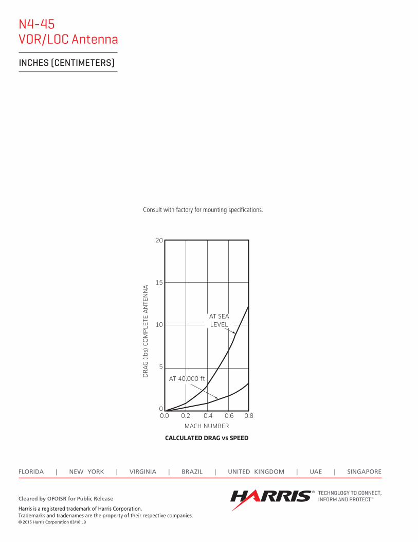
N4-45VOR/LOC Antenna
INCHES (CENTIMETERS)
Harris is a registered trademark of Harris Corporation. Trademarks and tradenames are the property of their respective companies.© 2015 Harris Corporation 03/16 LB
Cleared by OFOISR for Public Release
Consult with factory for mounting specifications.
DR
AG
(lb
s) C
OM
PLE
TE A
NTE
NN
A
20
15
10
5
00.0 0.2 0.4
MACH NUMBER
AT 40,000 ft
AT SEA LEVEL
0.6 0.8
CALCULATED DRAG vs SPEED