Embed Size (px)
Citation preview
T3 TREADMILLOwner’s Manual
8972901 REV B-3

1
AMERICAS
North AmericaLife Fitness Inc.5100 N River RoadSchiller Park, IL 60176 U.S.ATelephone: (847) 288 3300Fax: (847) 288 3703Service Telephone: (800) 351 3737Service Email: [email protected]/Marketing Email:
[email protected] Hours: 7:00 am-6:00 pm (CST)
Brazil Life Fitness BrasilAv. Cidade Jardim, 900Jd. PaulistanoSão Paulo, SP 01454-000BRAZILSAC: 0800 773 8282Telephone: +55 (11) 3095 5200Fax: +55 (11) 3095 5201Service Email: [email protected]/Marketing Email: [email protected] Operating Hours:
9:00 - 17:00 (BRT) (Monday-Friday)Store Operating Hours:
9:00 -20:00 (BRT) (Monday-Friday)10:00 - 16:00 (BRT) (Saturday)
Latin America & Caribbean*Life Fitness Inc.5100 N River RoadSchiller Park, IL 60176 U.S.ATelephone: (847) 288 3300Fax: (847) 288 3703Service Email: [email protected]/Marketing Email:[email protected] Hours: 7:00am-6:00pm (CST)
EUROPE, MIDDLE EAST, & AFRICA (EMEA)Netherlands & LuxemburgLife Fitness Atlantic BVBijdorpplein 25-312992 LB BarendrechtTHE NETHERLANDSTelephone: (+31) 180 646 666Fax: (+31) 180 646 699Service Email: [email protected]/Marketing Email:
[email protected] Hours: 9.00h-17.00h (CET)
United Kingdom & IrelandLife Fitness UK LTDQueen AdelaideEly, Cambs, CB7 4UBTelephone: General Office (+44) 1353.666017Customer Support (+44) 1353.665507Fax: (+44) 1353.666018Service Email: [email protected]/Marketing Email: [email protected] Hours:
General Office: 9.00am - 5.00pm (GMT)Customer Support: 8.30am - 5.00pm (GMT)
Germany & SwitzerlandLife Fitness Europe GMBHSiemensstraße 385716 UnterschleißheimGERMANYTelephone: (+49) 89.31 77 51.0 (Germany)
(+41) 0848 000 901 (Switzerland)Fax: (+49) 89.31 77 51.99 (Germany)(+41) 043 818 07 20 (Switzerland)Service Email: [email protected]/Marketing Email: [email protected] Hours: 08.30 -16.30h (CET)
AustriaLife Fitness AustriaVertriebs G.m.b.H.Dückegasse 7-9/3/36 1220 ViennaAUSTRIATelephone: (+43) 1.61.57.198Fax: (+43) 1.61.57.198.20Service Email: [email protected]/Sales Email: [email protected] Hours: 08:30-16.30.h (MEZ)
SpainLife Fitness IBERIAC/Frederic Mompou 5,1º1ª08960 Sant Just Desvern BarcelonaSPAINTelephone: (+34) 93.672.4660Fax: (+34) 93.672.4670Service Email: [email protected]/Marketing Email: [email protected] Hours:
9.00h-18.00h (Monday-Thursday)8.30h-15.00h (Friday)
BelgiumLife Fitness Benelux NVParc Industrial de Petit-Rechain4800 VerviersBELGIUMTelephone: (+32) 87 300 942Fax: (+32) 87 300 943Service Email: [email protected]/Marketing Email:[email protected] Hours: 9.00h -17.00h (CET)
ItalyLife Fitness Europe GmbHSiemensstraße 385716 UnterschleißheimGERMANYTelephone: (+39) 02-55378611 Service: 800438836 (In Italy)Fax: (+39) 02-55378699Service Email: [email protected]/Marketing Email: [email protected] Hours: 08:30 - 16:30h (CET)
All Other EMEA countries &Distributor Business C-EMEA*Bijdorpplein 25-312992 LB BarendrechtTHE NETHERLANDSTelephone: (+31) 180 646 644Fax: (+31) 180 646 699Service Email: [email protected]/Marketing Email:
[email protected] Hours: 9.00h-17.00h (CET)
ASIA PACIFIC (AP)JapanLife Fitness JapanNippon Brunswick Bldg., #8F5-27-7 SendagayaShibuya-Ku, TokyoJapan 151-0051Telephone: (+81) 3.3359.4309Fax: (+81) 3.3359.4307Service Email: [email protected] Sales/Marketing Email: [email protected] Hours: 9.00h-17.00h (JAPAN)
China and Hong KongLife Fitness Asia Pacific LTDRoom 2610, Miramar Tower132 Nathan RoadTsimshatsui, KowloonHONG KONGTelephone: (+852) 2891.6677Fax: (+852) 2575.6001Service Email: [email protected]/Marketing Email: [email protected] Hours: 9.00h-18.00h
All Other Asia Pacific countries &distributor business Asia Pacific*Room 2610, Miramar Tower132 Nathan RoadTsimshatsui, KowloonHONG KONGTelephone: (+852) 2891.6677Fax: (+852) 2575.6001Service Email: [email protected]/Marketing Email: [email protected] Hours: 9.00h-18.00h
CORPORATE HEADQUARTERS5100 River Road
Schiller Park, Illinois 60176 • U.S.A.847.288.3300 • FAX: 847.288.3703
Service phone number: 800.351.3737 (toll-free within U.S.A., Canada)
Global Website: www.lifefitness.com
INTERNATIONAL OFFICES
Before using this product, it is essential to read this ENTIRE operation manual and ALL installation instructions.
This will help in setting up the equipment quickly and in instructing others on how to use it correctly and safely.
Note: This equipment generates, uses and can radiate radio frequency energy, and if not installed and used in accor-dance with the operation manual, may cause harmful interference to radio communications. However, there is no guar-antee that the interference will not occur in a particular installation. If this equipment does cause harmful interference toradio or television reception, which can be determined by turning the equipment off and on, the user is encouraged to tryto correct the interference by one or more of the following measures:
• Re-orient or relocate the receiving antenna.• Increase the separation between the equipment and the receiver.• Connect the equipment into an outlet on a circuit different from that to which the receiver is connected.• Consult the dealer or an experienced radio/TV technician for help.
Class HB (Home): Domestic use.
CAUTION: Any changes or modifications to this equipment could void the product warranty.
Any service other than cleaning or user maintenance, must be performed by an authorized service representative. Thereare no user-serviceable parts.
2

3
TABLE OF CONTENTS
1. Important Safety Instructions . . . . . . . . . . . . . . . . . . . . . . . . . . . . . . . . . . . . . . . . . . . . . . . . . . . . . . . . . . .5
2. Life Fitness T3 Treadmill Design Illustration . . . . . . . . . . . . . . . . . . . . . . . . . . . . . . . . . . . . . . . . . . . . . . .7
3. Assembly . . . . . . . . . . . . . . . . . . . . . . . . . . . . . . . . . . . . . . . . . . . . . . . . . . . . . . . . . . . . . . . . . . . . . . . . . .8
3.1 Unpacking . . . . . . . . . . . . . . . . . . . . . . . . . . . . . . . . . . . . . . . . . . . . . . . . . . . . . . . . . . . . . . . . . . . . . . . . .8
3.2 Component List & Hardware . . . . . . . . . . . . . . . . . . . . . . . . . . . . . . . . . . . . . . . . . . . . . . . . . . . . . . . . . . .9
3.3 Installing Uprights and Handlebars . . . . . . . . . . . . . . . . . . . . . . . . . . . . . . . . . . . . . . . . . . . . . . . . . . . . .10
3.4 Installing the Console . . . . . . . . . . . . . . . . . . . . . . . . . . . . . . . . . . . . . . . . . . . . . . . . . . . . . . . . . . . . . . . .11
3.5 Attaching the Power Cord . . . . . . . . . . . . . . . . . . . . . . . . . . . . . . . . . . . . . . . . . . . . . . . . . . . . . . . . . . . .12
3.6 Calibration . . . . . . . . . . . . . . . . . . . . . . . . . . . . . . . . . . . . . . . . . . . . . . . . . . . . . . . . . . . . . . . . . . . . . . . . .12
4. Setup . . . . . . . . . . . . . . . . . . . . . . . . . . . . . . . . . . . . . . . . . . . . . . . . . . . . . . . . . . . . . . . . . . . . . . . . . . . .13
5. Activity Zone and Heart Rate Sensor Overview . . . . . . . . . . . . . . . . . . . . . . . . . . . . . . . . . . . . . . . . . . . .15
6. Service and Technical Data . . . . . . . . . . . . . . . . . . . . . . . . . . . . . . . . . . . . . . . . . . . . . . . . . . . . . . . . . . .17
6.1 Troubleshooting . . . . . . . . . . . . . . . . . . . . . . . . . . . . . . . . . . . . . . . . . . . . . . . . . . . . . . . . . . . . . . . . . . . .17
6.2 Preventive Maintenance Tips . . . . . . . . . . . . . . . . . . . . . . . . . . . . . . . . . . . . . . . . . . . . . . . . . . . . . . . . . .19
6.3 How to Adjust and Tension the Striding Belt . . . . . . . . . . . . . . . . . . . . . . . . . . . . . . . . . . . . . . . . . . . . . .20
6.4 Using and Testing the Safety Stop Pull Cord . . . . . . . . . . . . . . . . . . . . . . . . . . . . . . . . . . . . . . . . . . . . . .21
6.5 How to Obtain Product Service . . . . . . . . . . . . . . . . . . . . . . . . . . . . . . . . . . . . . . . . . . . . . . . . . . . . . . . .21
7. Specifications . . . . . . . . . . . . . . . . . . . . . . . . . . . . . . . . . . . . . . . . . . . . . . . . . . . . . . . . . . . . . . . . . . . . . .22
8. Warranty Information . . . . . . . . . . . . . . . . . . . . . . . . . . . . . . . . . . . . . . . . . . . . . . . . . . . . . . . . . . . . . . . .23
© 2011 Life Fitness, a division of Brunswick Corporation. All rights reserved.
4
This Operation Manual describes the functions of the following product:
Life Fitness Treadmill Model:
T3Thank you for purchasing a Life Fitness treadmill. Before using this product please read this user manual in its entiretyto ensure that you have the knowledge to safely and properly operate all of the features on your treadmill. We hope youachieve the product experience on your treadmill that you expect, but if you do have any service issues please go to theHow to Obtain Product Service section which will provide information on obtaining domestic and international productservice. See "Specifications" in this manual for product specific features.
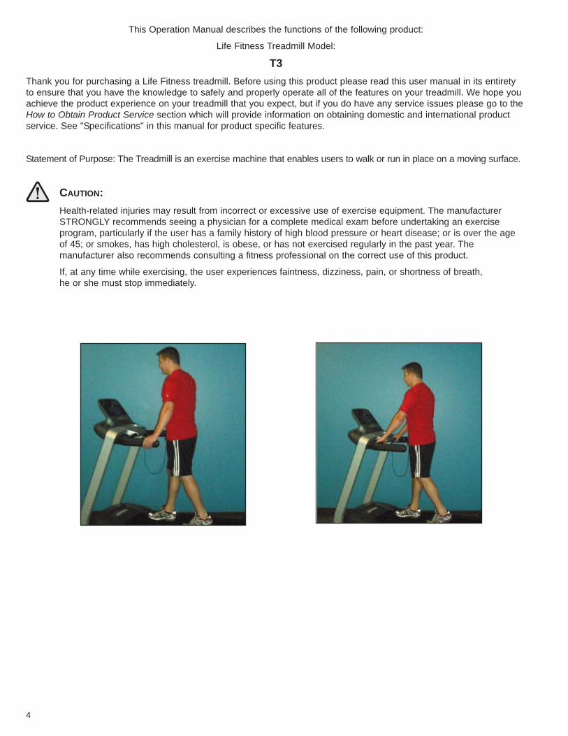
Statement of Purpose: The Treadmill is an exercise machine that enables users to walk or run in place on a moving surface.
CAUTION:Health-related injuries may result from incorrect or excessive use of exercise equipment. The manufacturerSTRONGLY recommends seeing a physician for a complete medical exam before undertaking an exercise program, particularly if the user has a family history of high blood pressure or heart disease; or is over the ageof 45; or smokes, has high cholesterol, is obese, or has not exercised regularly in the past year. The manufacturer also recommends consulting a fitness professional on the correct use of this product.
If, at any time while exercising, the user experiences faintness, dizziness, pain, or shortness of breath, he or she must stop immediately.
1 IMPORTANT SAFETY INSTRUCTIONSWARNING: READ ALL INSTRUCTIONS BEFORE USING THE TREADMILL. SAVE THESE INSTRUCTIONS.
DANGER: To reduce the risk of electrical shock, always unplug this Life Fitness product before cleaning or attempting any maintenance activity.
WARNING: To reduce the risk of burns, fire, electric shock, or injury, it is imperative to connect each product to aproperly grounded electrical outlet.
WARNING: This treadmill has immobilization software. Only activate the software immobilization when the treadmillis not in use. Refer to this Owner’s Manual for instructions on immobilizing the treadmill. Keep the instructions out ofthe reach of children.
WARNING: Do not move the treadmill by lifting the console. Do not use the console as a handlebar during a workout.
WARNING: Heart rate monitoring systems may be inaccurate. Over exercising may result in serious injury or death.If you feel faint stop exercising immediately.
WARNING: Any adjustment devices that could interfere with the user’s movement should not be left projecting.
WARNING: Equipment should be installed on a stable base and be properly leveled.
Risk of injury to persons – To avoid injury use extreme caution when stepping onto or off of a moving belt.
• To disconnect, turn power OFF at the ON/OFF switch, then remove plug from electrical outlet.
• Never operate a Life Fitness product if it has a damaged power cord or electrical plug, or if it has been dropped,damaged, or even partially immersed in water. Contact Life Fitness Customer Services.
• Position this product so the power cord plug is accessible to the user.
• Keep the power cord away from heated surfaces. Do not pull the equipment by the power cord or use the cordas a handle. Do not run the power cord on the floor, under or along the side of the treadmill.
• If the electrical supply cord is damaged it must be replaced by the manufacturer, an authorized service agent, ora similarly qualified person to avoid a hazard.
• Do not use this product in areas where aerosol spray products are being used or where oxygen is being administered. Such substances create the danger of combustion and explosion.
• Always follow the console instructions for proper operation.
• This appliance is not intended for use by persons (including children) with reduced physical, sensory or mentalcapabilities, or lack of experience and knowledge, unless they have been given supervision or instruction con-cerning use of the appliance by a person responsible for their safety.
• Children should be supervised to ensure that they do not play with the appliance.
• Do not use this product outdoors, near swimming pools, or in areas of high humidity.
• Never operate a Life Fitness product with the air openings blocked. Keep air openings free of lint, hair or anyobstructing material.
• Never insert objects into any openings in this product. If an object should drop inside, turn off the power, unplugthe power cord from the outlet and carefully retrieve it. If the item cannot be reached, contact Life FitnessCustomer Services.
• Never place liquids of any type directly on the unit, except in a bottle holder or accessory tray. Lidded containersare recommended.
• When using the treadmill, wear shoes with rubber or high traction soles. Do not use shoes with heels, leathersoles, cleats or spikes. Make sure no stones are embedded in the soles. Do not use this product in bare feet.Keep all loose clothing, shoelaces and towels away from moving parts.
• Do not reach into or underneath the unit, or tip it on its side during operation.
• Keep an open area of 6.5 feet (2 meters) by 3 feet (1 meter) behind the treadmill clear of any obstructions,including walls, furniture and other equipment.
• Allow LCD consoles to “normalize” with respect to temperature for one hour before plugging the unit in and/orusing.
5
• Use the handrails whenever additional stability is required. In case of emergency, such as tripping, the usershould grab the handrails and place his/her feet on the side platforms. The handrails may be held to enhancestability as needed, but are not for continuous use.
• Never walk or jog backwards on the treadmill.• Immobilize the treadmill so the motors will not run when the unit is not in use. To do this, press and hold both
the SPEED DOWN ARROW and the STOP key on the activity zone.• Use this unit only for its intended use as described in this manual. Do not use attachments not recommended by
the manufacturer.• In conformity with the European Union Machinery directive 2006/42/EC, this equipment runs at sound pressure
levels below 70 dB(A) at the average operating speed of 8 km/hr.• The universal electrical grounding symbol is:
6
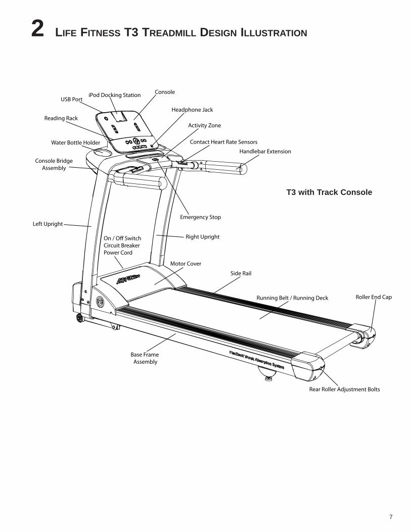
2 LIFE FITNESS T3 TREADMILL DESIGN ILLUSTRATION
Water Bottle Holder
Reading Rack
iPod Docking Station Console
Emergency Stop
Contact Heart Rate Sensors
Motor Cover
Side Rail
Running Belt / Running Deck
Rear Roller Adjustment Bolts
Roller End Cap
On / Off SwitchCircuit BreakerPower Cord
Activity Zone
USB Port
Headphone Jack
Handlebar Extension
Right Upright
Base Frame Assembly
Left Upright
Console BridgeAssembly
7
T3 with Track Console
3 ASSEMBLYFor safety, and to save time and effort, read this Owner’s Manual completely before installing your Life Fitness Treadmill.Place the treadmill near where it will be used before beginning the unpacking procedure.
3.1 UNPACKING
These unpacking instructions assume you have already done the following:
• Removed the top of the shipping carton.
• Removed the styrofoam packing material.
• Removed these assembly instructions from the bridge assembly carton.
The best method for unpacking the rest of the treadmill proceeds as follows:
• Remove the bridge assembly carton from the base unit.
• Break down the sides of the inner shipping carton.
• Remove the treadmill uprights from the shipping carton.
• Assemble the treadmill. Once assembly is complete:
- Roll the treadmill off of the shipping carton and to the location where it will be used.
8
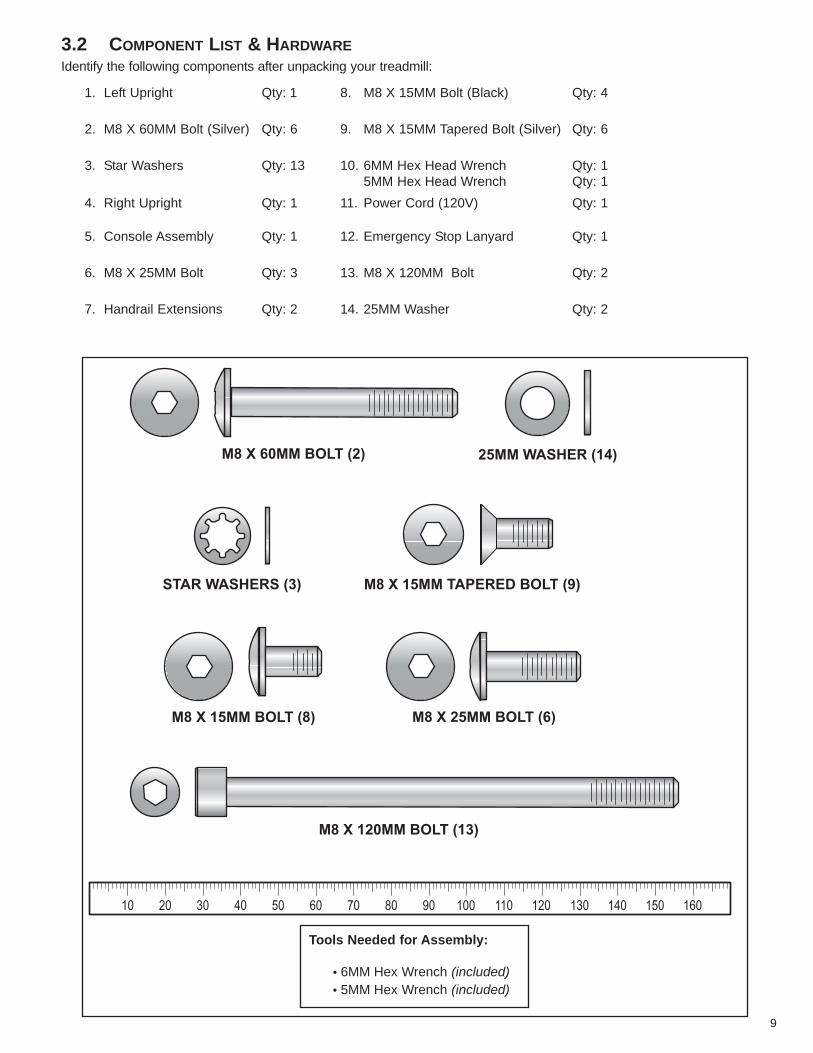
3.2 COMPONENT LIST & HARDWAREIdentify the following components after unpacking your treadmill:
M8 X 60MM BOLT (2)
STAR WASHERS (3)
25MM WASHER (14)
M8 X 15MM TAPERED BOLT (9)
M8 X 15MM BOLT (8) M8 X 25MM BOLT (6)
M8 X 120MM BOLT (13)
10 706020 8030 9040 100 12050 110 130 140 150 160
Tools Needed for Assembly:
• 6MM Hex Wrench (included)• 5MM Hex Wrench (included)
1. Left Upright Qty: 1 8. M8 X 15MM Bolt (Black) Qty: 4
2. M8 X 60MM Bolt (Silver) Qty: 6 9. M8 X 15MM Tapered Bolt (Silver) Qty: 6
3. Star Washers Qty: 13 10. 6MM Hex Head Wrench5MM Hex Head Wrench
Qty: 1Qty: 1
4. Right Upright Qty: 1 11. Power Cord (120V) Qty: 1
5. Console Assembly Qty: 1 12. Emergency Stop Lanyard Qty: 1
6. M8 X 25MM Bolt Qty: 3 13. M8 X 120MM Bolt Qty: 2
7. Handrail Extensions Qty: 2 14. 25MM Washer Qty: 2
9
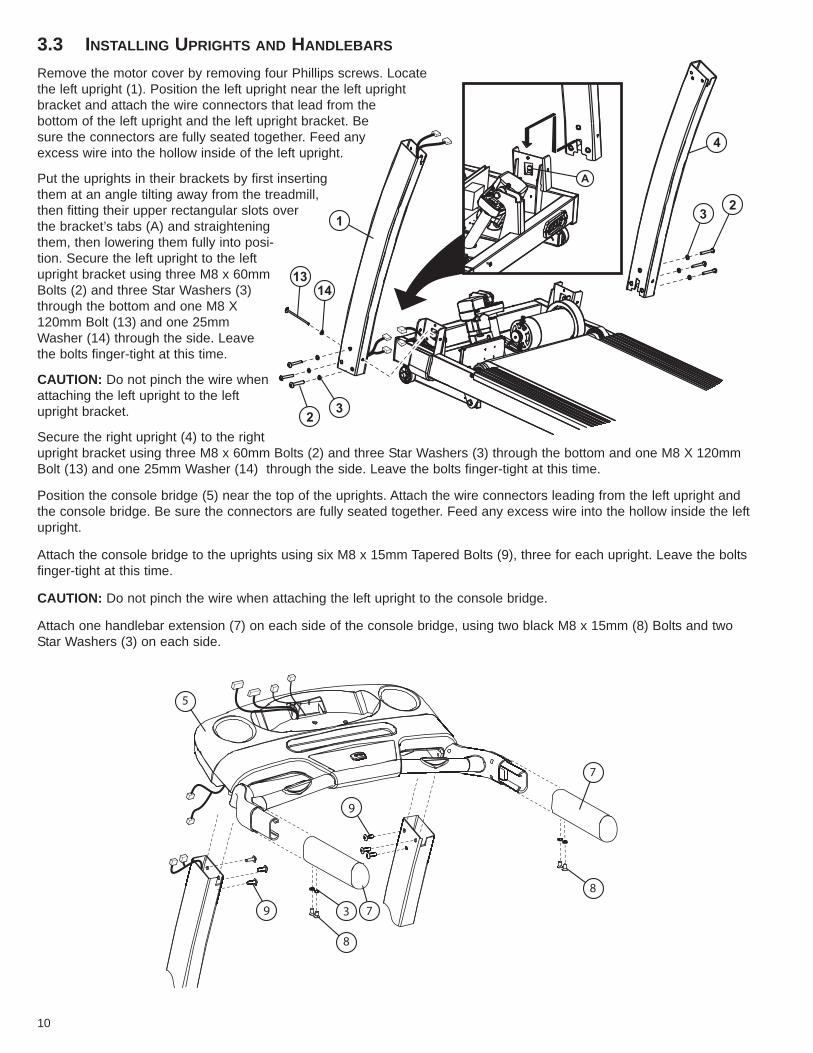
3.3 INSTALLING UPRIGHTS AND HANDLEBARS
Remove the motor cover by removing four Phillips screws. Locatethe left upright (1). Position the left upright near the left uprightbracket and attach the wire connectors that lead from thebottom of the left upright and the left upright bracket. Besure the connectors are fully seated together. Feed anyexcess wire into the hollow inside of the left upright.
Put the uprights in their brackets by first insertingthem at an angle tilting away from the treadmill,then fitting their upper rectangular slots overthe bracket’s tabs (A) and straighteningthem, then lowering them fully into posi-tion. Secure the left upright to the leftupright bracket using three M8 x 60mmBolts (2) and three Star Washers (3)through the bottom and one M8 X120mm Bolt (13) and one 25mmWasher (14) through the side. Leavethe bolts finger-tight at this time.
CAUTION: Do not pinch the wire whenattaching the left upright to the leftupright bracket.
Secure the right upright (4) to the rightupright bracket using three M8 x 60mm Bolts (2) and three Star Washers (3) through the bottom and one M8 X 120mmBolt (13) and one 25mm Washer (14) through the side. Leave the bolts finger-tight at this time.
Position the console bridge (5) near the top of the uprights. Attach the wire connectors leading from the left upright andthe console bridge. Be sure the connectors are fully seated together. Feed any excess wire into the hollow inside the leftupright.
Attach the console bridge to the uprights using six M8 x 15mm Tapered Bolts (9), three for each upright. Leave the boltsfinger-tight at this time.
CAUTION: Do not pinch the wire when attaching the left upright to the console bridge.
Attach one handlebar extension (7) on each side of the console bridge, using two black M8 x 15mm (8) Bolts and twoStar Washers (3) on each side.
13
14
39
9
7
8
8
7
5
10
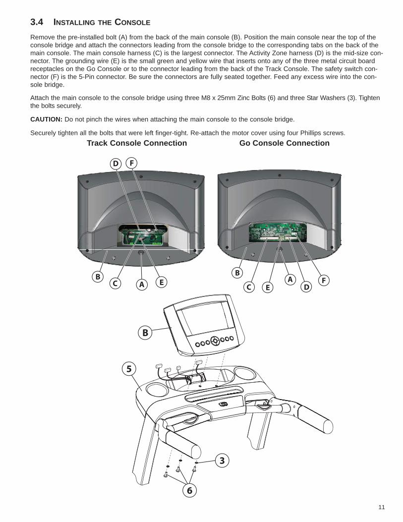
3.4 INSTALLING THE CONSOLE
Remove the pre-installed bolt (A) from the back of the main console (B). Position the main console near the top of theconsole bridge and attach the connectors leading from the console bridge to the corresponding tabs on the back of themain console. The main console harness (C) is the largest connector. The Activity Zone harness (D) is the mid-size con-nector. The grounding wire (E) is the small green and yellow wire that inserts onto any of the three metal circuit boardreceptacles on the Go Console or to the connector leading from the back of the Track Console. The safety switch con-nector (F) is the 5-Pin connector. Be sure the connectors are fully seated together. Feed any excess wire into the con-sole bridge.
Attach the main console to the console bridge using three M8 x 25mm Zinc Bolts (6) and three Star Washers (3). Tightenthe bolts securely.
CAUTION: Do not pinch the wires when attaching the main console to the console bridge.
Securely tighten all the bolts that were left finger-tight. Re-attach the motor cover using four Phillips screws.
B
C EA
DF
B
5
6
3
BA
D
C
F
E
11
Go Console ConnectionTrack Console Connection
3.5 ATTACHING THE POWER CORD
Insert the female plug of your treadmill’s power cord into the male outlet next to your treadmill’s power switch.Note: T3 treadmills shipped in the USA and Canada are supplied with a North American line cord. Attach the cord suitedto your area.
3.6 CALIBRATION
Before using your treadmill please follow the calibration instructions below. Please stand to the side of your treadmillduring calibration.
1. Turn treadmill on, or if on press the RESET key.
2. The console will display "PLEASE WAIT" or "WAIT".
3. When "PLEASE WAIT" or "WAIT" disappears and the screen is blank press and hold the PAUSE key until"DIAGNOSTICS" appears.
4. Use the arrow keys to scroll through the diagnostics menu to "CALIBRATION" or "CALIB".
5. Press enter to select "CALIBRATION" or "CALIB".
6. Press the START key located on the activity zone to begin calibration.
7. Your treadmill will now automatically cycle through a series of tests including speed and incline adjustments inorder to complete calibration.
8. When successfully completed the console will display "PASS".
***If there was an error during calibration the console will display "FAIL".
***If a failure occurred press STOP twice and restart the process at Step 1.
***If failure occurs again take note of the error number display and contact Life Fitness customer support at 1-800-351-3737 (U.S.A. and Canada).
9. Upon successful completion press the RESET key three times to exit calibration mode.
12
4 SETUP
ELECTRICAL POWER REQUIREMENTSMost Life Fitness Treadmills are intended for use on a normal 120 volt circuit in the United States and Canada. Below isa table that provides the current rating for this product based on supply voltage. Make sure that the treadmill model sup-ports the proper line voltage for the installation location before plugging into the outlet. Line voltage is noted on the prod-uct’s serial label.
Supply Voltage (VAC) Frequency (Hz) Maximum Current (Amps)120 50 / 60 12230 50 / 60 10
ELECTRICAL GROUNDING REQUIREMENTS
This Life Fitness product must be properly grounded. If the unit malfunctions or breaks down, proper grounding provides the path of least resistance for the electric current, which reduces the risk of shock to anyone touching or usingthe equipment. Each unit is equipped with an electrical cord, which includes an equipment grounding conductor and agrounding plug. The plug must be inserted into an outlet that has been properly installed and grounded in accordancewith all local codes and ordinances. A temporary adapter must not be used to connect this plug to a two-pole receptaclein North America. If a properly grounded, correct amperage outlet is not available, a qualified electrician must install one.
DANGER: A risk of electrical shock may result from improper connection of the equipment’s grounding conductor. Checkwith a qualified electrician if you are unsure about proper grounding techniques. Do not modify the plug provided withthis product. If it will not fit an electrical outlet, have a proper outlet installed by a qualified electrician.
TURNING THE UNIT ON
To turn the treadmill on, locate the ON/OFF power switch at the front of the treadmill near the power cord and turn it ON.
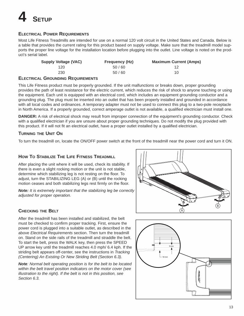
HOW TO STABILIZE THE LIFE FITNESS TREADMILL
After placing the unit where it will be used, check its stability. Ifthere is even a slight rocking motion or the unit is not stable,determine which stabilizing leg is not resting on the floor. Toadjust, turn the STABILIZING LEG (A) or (B) until the rockingmotion ceases and both stabilizing legs rest firmly on the floor.
Note: It is extremely important that the stabilizing leg be correctlyadjusted for proper operation.
CHECKING THE BELT
After the treadmill has been installed and stabilized, the beltmust be checked to confirm proper tracking. First, ensure thepower cord is plugged into a suitable outlet, as described in theabove Electrical Requirements section. Then turn the treadmillon. Stand on the side rails of the treadmill and straddle the belt.To start the belt, press the WALK key, then press the SPEEDUP arrow key until the treadmill reaches 4.0 mph/ 6.4 kph. If thestriding belt appears off-center, see the instructions in Tracking(Centering) An Existing Or New Striding Belt (Section 6.3).
Note: Normal belt operating position is for the belt to be locatedwithin the belt travel position indicators on the motor cover (seeillustration to the right). If the belt is not in this position, seeSection 6.3.
AB
9 mm
18 mm
13

POWER SWITCH
Located on the front panel at the base of the treadmill, the ON/OFF switch has two positions - "I" (one) for ON and "0"(zero) for OFF.
IMMOBILIZING THE TREADMILL
When it is necessary to immobilize the treadmill, press and hold both the SPEED DOWN ARROW and the STOP keyson the activity zone. Use the same key sequence to mobilize the treadmill.
14
5 ACTIVITY ZONE AND HEART RATE SENSOR OVERVIEW
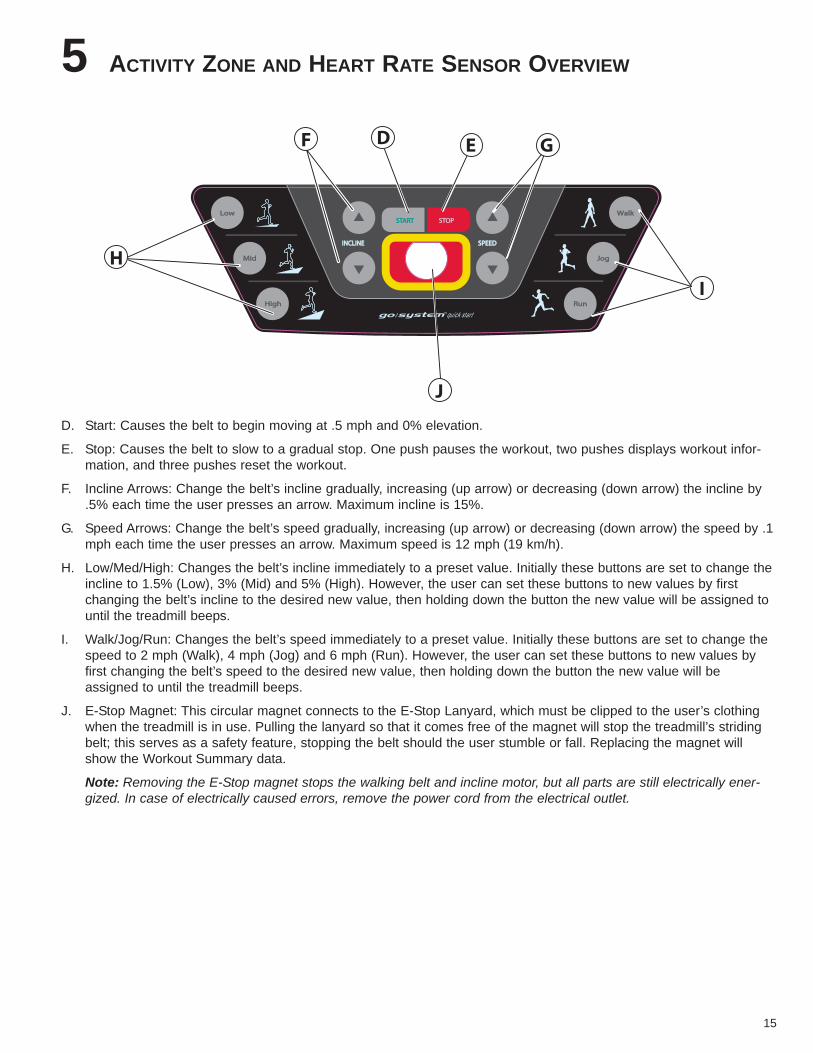
D. Start: Causes the belt to begin moving at .5 mph and 0% elevation.
E. Stop: Causes the belt to slow to a gradual stop. One push pauses the workout, two pushes displays workout infor-mation, and three pushes reset the workout.
F. Incline Arrows: Change the belt’s incline gradually, increasing (up arrow) or decreasing (down arrow) the incline by.5% each time the user presses an arrow. Maximum incline is 15%.
G. Speed Arrows: Change the belt’s speed gradually, increasing (up arrow) or decreasing (down arrow) the speed by .1mph each time the user presses an arrow. Maximum speed is 12 mph (19 km/h).
H. Low/Med/High: Changes the belt’s incline immediately to a preset value. Initially these buttons are set to change theincline to 1.5% (Low), 3% (Mid) and 5% (High). However, the user can set these buttons to new values by firstchanging the belt’s incline to the desired new value, then holding down the button the new value will be assigned tountil the treadmill beeps.
I. Walk/Jog/Run: Changes the belt’s speed immediately to a preset value. Initially these buttons are set to change thespeed to 2 mph (Walk), 4 mph (Jog) and 6 mph (Run). However, the user can set these buttons to new values byfirst changing the belt’s speed to the desired new value, then holding down the button the new value will beassigned to until the treadmill beeps.
J. E-Stop Magnet: This circular magnet connects to the E-Stop Lanyard, which must be clipped to the user’s clothingwhen the treadmill is in use. Pulling the lanyard so that it comes free of the magnet will stop the treadmill’s stridingbelt; this serves as a safety feature, stopping the belt should the user stumble or fall. Replacing the magnet willshow the Workout Summary data.
Note: Removing the E-Stop magnet stops the walking belt and incline motor, but all parts are still electrically ener-gized. In case of electrically caused errors, remove the power cord from the electrical outlet.
STARTSTART STOPSTOP
RunRun
WalkWalk
JogJog
LowLow
MidMid
HighHigh
INCLINEINCLINE SPEEDSPEED
F
I
J
D E G
H
15
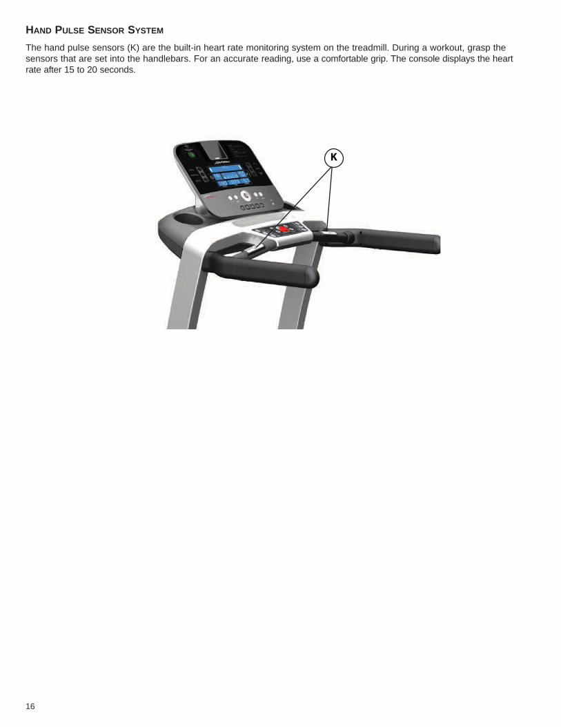
HAND PULSE SENSOR SYSTEM
The hand pulse sensors (K) are the built-in heart rate monitoring system on the treadmill. During a workout, grasp thesensors that are set into the handlebars. For an accurate reading, use a comfortable grip. The console displays the heartrate after 15 to 20 seconds.
K
16
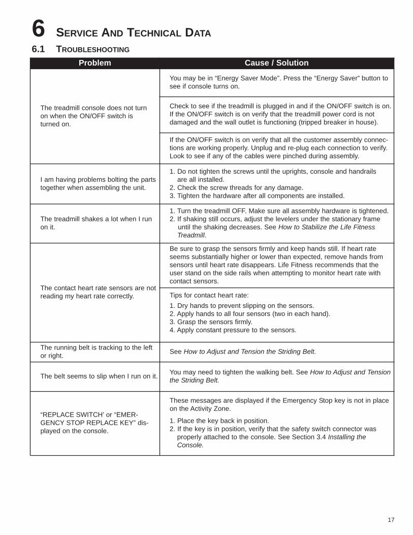
6 SERVICE AND TECHNICAL DATA6.1 TROUBLESHOOTING
Problem Cause / Solution
The treadmill console does not turn on when the ON/OFF switch is turned on.
You may be in “Energy Saver Mode”. Press the “Energy Saver” button tosee if console turns on.
Check to see if the treadmill is plugged in and if the ON/OFF switch is on.If the ON/OFF switch is on verify that the treadmill power cord is not damaged and the wall outlet is functioning (tripped breaker in house).
If the ON/OFF switch is on verify that all the customer assembly connec-tions are working properly. Unplug and re-plug each connection to verify.Look to see if any of the cables were pinched during assembly.
I am having problems bolting the partstogether when assembling the unit.
1. Do not tighten the screws until the uprights, console and handrails are all installed.
2. Check the screw threads for any damage.3. Tighten the hardware after all components are installed.
The treadmill shakes a lot when I runon it.
1. Turn the treadmill OFF. Make sure all assembly hardware is tightened.2. If shaking still occurs, adjust the levelers under the stationary frame
until the shaking decreases. See How to Stabilize the Life FitnessTreadmill.
The contact heart rate sensors are notreading my heart rate correctly.
Be sure to grasp the sensors firmly and keep hands still. If heart rateseems substantially higher or lower than expected, remove hands fromsensors until heart rate disappears. Life Fitness recommends that theuser stand on the side rails when attempting to monitor heart rate withcontact sensors.
Tips for contact heart rate:1. Dry hands to prevent slipping on the sensors.2. Apply hands to all four sensors (two in each hand).3. Grasp the sensors firmly.4. Apply constant pressure to the sensors.
The running belt is tracking to the leftor right. See How to Adjust and Tension the Striding Belt.
The belt seems to slip when I run on it. You may need to tighten the walking belt. See How to Adjust and Tensionthe Striding Belt.
“REPLACE SWITCH’ or “EMER-GENCY STOP REPLACE KEY” dis-played on the console.
These messages are displayed if the Emergency Stop key is not in placeon the Activity Zone.
1. Place the key back in position.2. If the key is in position, verify that the safety switch connector was
properly attached to the console. See Section 3.4 Installing the Console.
17
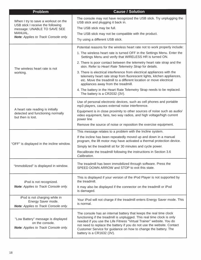
Problem Cause / Solution
When I try to save a workout on theUSB stick I receive the following message: UNABLE TO SAVE SEEMANUAL.Note: Applies to Track Console only.
The console may not have recognized the USB stick. Try unplugging theUSB stick and plugging it back in.
The USB stick may be full.
The USB stick may not be compatible with the product.
Try using a different USB stick.
The wireless heart rate is not working.
Potential reasons for the wireless heart rate not to work properly include:
1. The wireless heart rate is turned OFF in the Settings Menu. Enter the Settings Menu and verify that WIRELESS HR is turned ON.
2. There is poor contact between the telemetry heart rate strap and theskin. Refer to Heart Rate Telemetry Strap for details.
3. There is electrical interference from electrical appliances with thetelemetry heart rate strap from fluorescent lights, kitchen appliances,etc. Move the treadmill to a different location or move electrical appliances away from the treadmill.
4. The battery in the Heart Rate Telemetry Strap needs to be replaced.The battery is a CR2032 (3V).
A heart rate reading is initially detected and functioning normally but then is lost.
Use of personal electronic devices, such as cell phones and portable mp3 players, causes external noise interference.
Equipment is in close proximity to other sources of noise such as audio/video equipment, fans, two way radios, and high voltage/high currentpower line
Remove the source of noise or reposition the exercise equipment.
“OFF” is displayed in the incline window.
This message relates to a problem with the Incline system.
If the incline has been repeatedly moved up and down in a manual program, the lift motor may have activated a thermal protection device.
Simply let the treadmill sit for 30 minutes and cycle power.
Recalibrate the treadmill following the instructions in Section 3.6Calibration.
“Immobilized” is displayed in window. The treadmill has been immobilized through software. Press the SPEED DOWN ARROW and STOP to exit this state.
iPod is not recognized.Note: Applies to Track Console only.
This is displayed if your version of the iPod Player is not supported by the treadmill.
It may also be displayed if the connector on the treadmill or iPod is damaged.
iPod is not charging while in Energy Saver mode.
Note: Applies to Track Console only.
Your iPod will not charge if the treadmill enters Energy Saver mode. Thisis normal.
”Low Battery” message is displayed on the console.
Note: Applies to Track Console only.
The console has an internal battery that keeps the real time clock functioning if the treadmill is unplugged. This real time clock is only needed if you use the Life Fitness ”Virtual Trainer” website. You do not need to replace the battery if you do not use the website. ContactCustomer Service for guidance on how to change the battery. The battery is a CR1632 (3V).
18
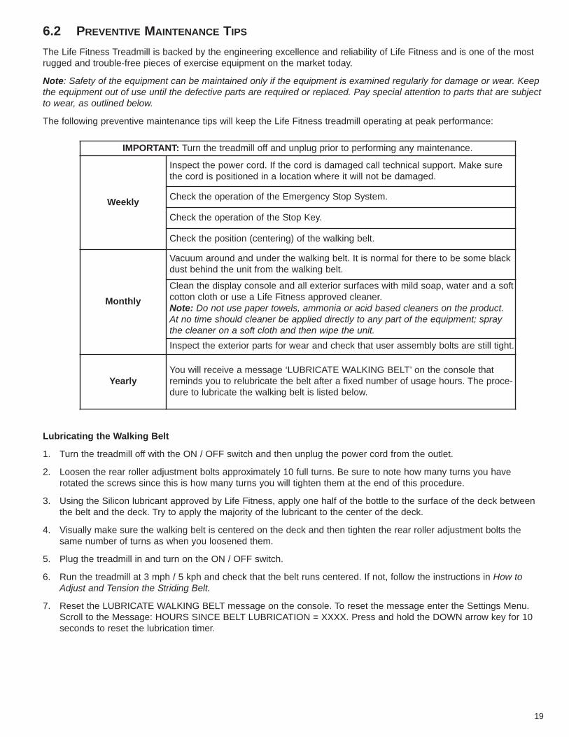
6.2 PREVENTIVE MAINTENANCE TIPS
The Life Fitness Treadmill is backed by the engineering excellence and reliability of Life Fitness and is one of the mostrugged and trouble-free pieces of exercise equipment on the market today.
Note: Safety of the equipment can be maintained only if the equipment is examined regularly for damage or wear. Keepthe equipment out of use until the defective parts are required or replaced. Pay special attention to parts that are subjectto wear, as outlined below.
The following preventive maintenance tips will keep the Life Fitness treadmill operating at peak performance:
Lubricating the Walking Belt
1. Turn the treadmill off with the ON / OFF switch and then unplug the power cord from the outlet.
2. Loosen the rear roller adjustment bolts approximately 10 full turns. Be sure to note how many turns you have rotated the screws since this is how many turns you will tighten them at the end of this procedure.
3. Using the Silicon lubricant approved by Life Fitness, apply one half of the bottle to the surface of the deck betweenthe belt and the deck. Try to apply the majority of the lubricant to the center of the deck.
4. Visually make sure the walking belt is centered on the deck and then tighten the rear roller adjustment bolts thesame number of turns as when you loosened them.
5. Plug the treadmill in and turn on the ON / OFF switch.
6. Run the treadmill at 3 mph / 5 kph and check that the belt runs centered. If not, follow the instructions in How toAdjust and Tension the Striding Belt.
7. Reset the LUBRICATE WALKING BELT message on the console. To reset the message enter the Settings Menu.Scroll to the Message: HOURS SINCE BELT LUBRICATION = XXXX. Press and hold the DOWN arrow key for 10seconds to reset the lubrication timer.
IMPORTANT: Turn the treadmill off and unplug prior to performing any maintenance.
Weekly
Inspect the power cord. If the cord is damaged call technical support. Make sure the cord is positioned in a location where it will not be damaged.
Check the operation of the Emergency Stop System.
Check the operation of the Stop Key.
Check the position (centering) of the walking belt.
Monthly
Vacuum around and under the walking belt. It is normal for there to be some blackdust behind the unit from the walking belt.
Clean the display console and all exterior surfaces with mild soap, water and a softcotton cloth or use a Life Fitness approved cleaner. Note: Do not use paper towels, ammonia or acid based cleaners on the product.At no time should cleaner be applied directly to any part of the equipment; spraythe cleaner on a soft cloth and then wipe the unit. Inspect the exterior parts for wear and check that user assembly bolts are still tight.
YearlyYou will receive a message ‘LUBRICATE WALKING BELT’ on the console that reminds you to relubricate the belt after a fixed number of usage hours. The proce-dure to lubricate the walking belt is listed below.
19
LIFE FITNESS APPROVED CLEANERS
Two preferred cleaners have been approved by Life Fitness reliability experts: PureGreen 24 and Gym Wipes. Bothcleaners will safely and effectively remove dirt, grime and sweat from equipment. PureGreen 24 and the AntibacterialForce formula of Gym Wipes are both disinfectants that are effective against MRSA and H1N1.
PureGreen 24 is available in a convenient spray. Apply the spray to a microfiber cloth and wipe down the equipment.Use PureGreen 24 on the equipment for at least 2 minutes for general disinfection purposes and at least 10 minutes forfungus and viral control.
Gym Wipes are large, durable pre-moistened wipes to use on the equipment before and after workouts. Use Gym Wipeson the equipment for at least 2 minutes for general disinfection purposes.
Contact Life Fitness Customer Support Services to order these cleaners. Call 1-800-351-3737 or email: [email protected].
LIFE FITNESS COMPATIBLE CLEANERS
Mild soap and water or a mild non-abrasive household cleaner can also be used to clean the display and all exterior sur-faces. Use a soft cotton cloth only. Apply the cleaner to the cotton cloth before cleaning. DO NOT use ammonia or acidbased cleaners. DO NOT use abrasive cleaners. DO NOT use paper towels. DO NOT apply cleaners directly to theequipment surfaces.
6.3 HOW TO ADJUST AND TENSION THE STRIDING BELT
Do not move the treadmill or place hands under the treadmill while it is plugged into an electrical outlet!
Tool Required: 6MM Hex Key Wrench
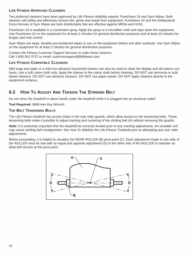
THE BELT TENSIONING BOLTS
The Life Fitness treadmill has access holes in the rear roller guards, which allow access to the tensioning bolts. Thesetensioning bolts make it possible to adjust tracking and centering of the striding belt (A) without removing the guards.
Note: It is extremely important that the treadmill be correctly leveled prior to any tracking adjustments. An unstable unitmay cause striding belt misalignment. See How To Stabilize the Life Fitness Treadmill prior to attempting any rear rolleradjustments.
Before proceeding, it is helpful to visualize the REAR ROLLER (B) pivot point (C). Each adjustment made to one side ofthe ROLLER must be met with an equal and opposite adjustment (D) to the other side of the ROLLER to maintain anideal belt tension at the pivot point.
20
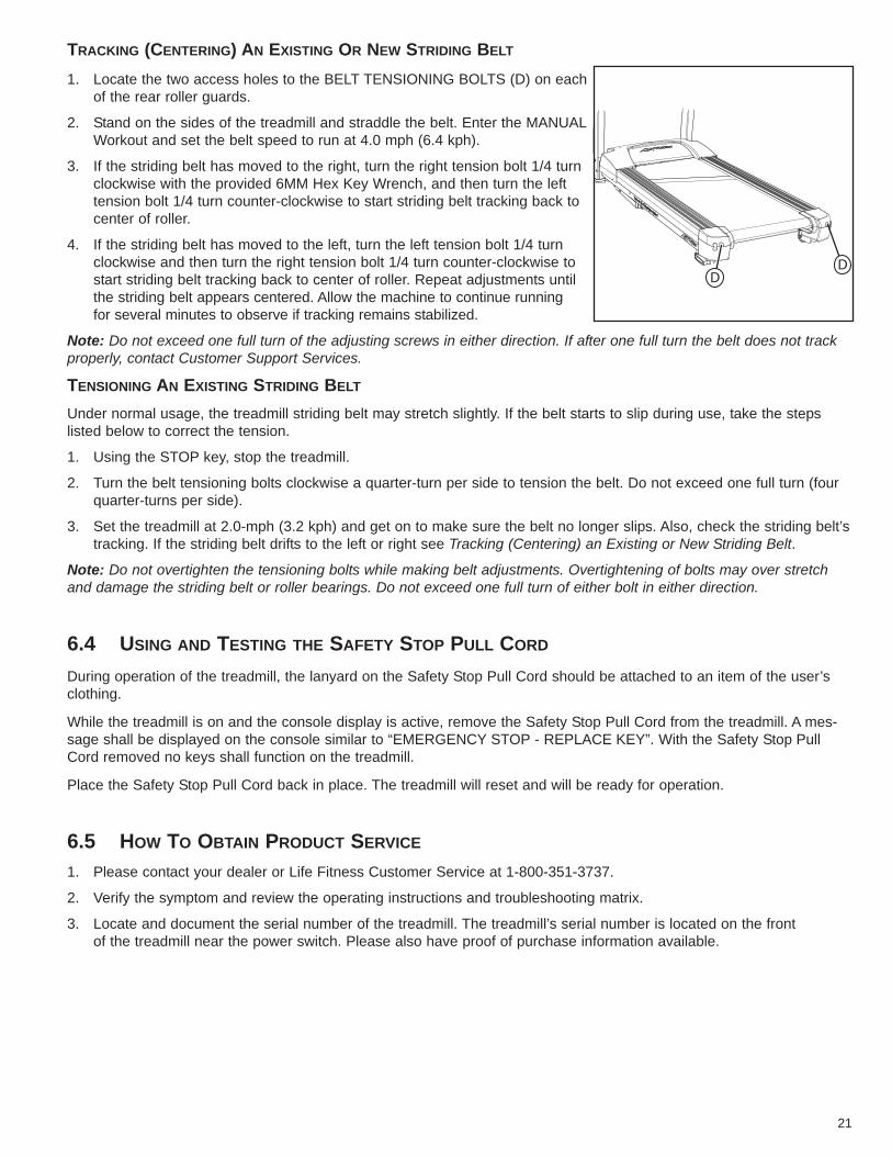
TRACKING (CENTERING) AN EXISTING OR NEW STRIDING BELT
1. Locate the two access holes to the BELT TENSIONING BOLTS (D) on eachof the rear roller guards.
2. Stand on the sides of the treadmill and straddle the belt. Enter the MANUALWorkout and set the belt speed to run at 4.0 mph (6.4 kph).
3. If the striding belt has moved to the right, turn the right tension bolt 1/4 turnclockwise with the provided 6MM Hex Key Wrench, and then turn the lefttension bolt 1/4 turn counter-clockwise to start striding belt tracking back tocenter of roller.
4. If the striding belt has moved to the left, turn the left tension bolt 1/4 turnclockwise and then turn the right tension bolt 1/4 turn counter-clockwise tostart striding belt tracking back to center of roller. Repeat adjustments untilthe striding belt appears centered. Allow the machine to continue running for several minutes to observe if tracking remains stabilized.
Note: Do not exceed one full turn of the adjusting screws in either direction. If after one full turn the belt does not trackproperly, contact Customer Support Services.
TENSIONING AN EXISTING STRIDING BELT
Under normal usage, the treadmill striding belt may stretch slightly. If the belt starts to slip during use, take the steps listed below to correct the tension.
1. Using the STOP key, stop the treadmill.
2. Turn the belt tensioning bolts clockwise a quarter-turn per side to tension the belt. Do not exceed one full turn (fourquarter-turns per side).
3. Set the treadmill at 2.0-mph (3.2 kph) and get on to make sure the belt no longer slips. Also, check the striding belt’stracking. If the striding belt drifts to the left or right see Tracking (Centering) an Existing or New Striding Belt.
Note: Do not overtighten the tensioning bolts while making belt adjustments. Overtightening of bolts may over stretchand damage the striding belt or roller bearings. Do not exceed one full turn of either bolt in either direction.
6.4 USING AND TESTING THE SAFETY STOP PULL CORD
During operation of the treadmill, the lanyard on the Safety Stop Pull Cord should be attached to an item of the user’sclothing.
While the treadmill is on and the console display is active, remove the Safety Stop Pull Cord from the treadmill. A mes-sage shall be displayed on the console similar to “EMERGENCY STOP - REPLACE KEY”. With the Safety Stop PullCord removed no keys shall function on the treadmill.
Place the Safety Stop Pull Cord back in place. The treadmill will reset and will be ready for operation.
6.5 HOW TO OBTAIN PRODUCT SERVICE
1. Please contact your dealer or Life Fitness Customer Service at 1-800-351-3737.
2. Verify the symptom and review the operating instructions and troubleshooting matrix.
3. Locate and document the serial number of the treadmill. The treadmill’s serial number is located on the front of the treadmill near the power switch. Please also have proof of purchase information available.
DD
21
22
7 SPECIFICATIONS
LIFE FITNESS T3 TREADMILL SPECIFICATIONS
Designed use: Home
Maximum user weight: 350 pounds / 159 kilograms
Speed range: 0.5 - 12.0 mph (0.8 - 19 km/h) in 0.1 increments
Elevation range: 0%-15% (in 0.5% increments)
Motor: 3 HP continuous duty DC
Rollers: Front: 2.6" (67mm) precision crowned
Back: 2.0" (50mm) precision crowned
Belt: 60" Length x 20" Width (152cm Length x 50cm Width), multi-ply
Deck: Flex Deck cushioning, not reversible
Handrails: Ergo Crossbar with side handrails.
Accessory tray: Standard, designed into system
Warranty: 10 years motor, 5 years parts,
3 years console, 1 year labor, and
lifetime on frame and springs
Physical Dimensions:
Length: 79.5 inches / 202 centimeters
Width: 34.5 inches / 88 centimeters
Height: 57.5 inches / 146 centimeters
Weight: 243 pounds / 110 kilograms
Shipping Dimensions:
Carton Length: 86.25 inches / 219 centimeters
Carton Width: 33 inches / 84 centimeters
Carton Height: 14 inches / 35.5 centimeters
Total Weight: 270 pounds / 122.5 kilograms
8 WARRANTY INFORMATION
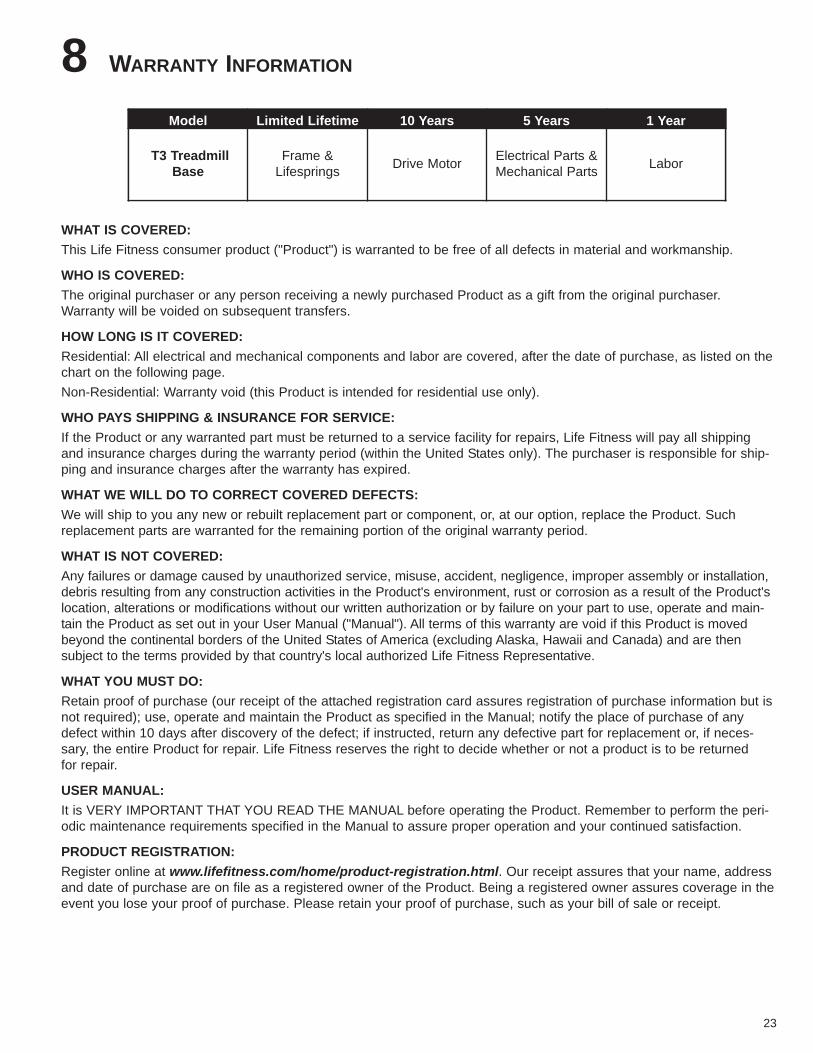
WHAT IS COVERED:This Life Fitness consumer product ("Product") is warranted to be free of all defects in material and workmanship.
WHO IS COVERED:The original purchaser or any person receiving a newly purchased Product as a gift from the original purchaser.Warranty will be voided on subsequent transfers.
HOW LONG IS IT COVERED:Residential: All electrical and mechanical components and labor are covered, after the date of purchase, as listed on thechart on the following page. Non-Residential: Warranty void (this Product is intended for residential use only).
WHO PAYS SHIPPING & INSURANCE FOR SERVICE:If the Product or any warranted part must be returned to a service facility for repairs, Life Fitness will pay all shippingand insurance charges during the warranty period (within the United States only). The purchaser is responsible for ship-ping and insurance charges after the warranty has expired.
WHAT WE WILL DO TO CORRECT COVERED DEFECTS:We will ship to you any new or rebuilt replacement part or component, or, at our option, replace the Product. Suchreplacement parts are warranted for the remaining portion of the original warranty period.
WHAT IS NOT COVERED:Any failures or damage caused by unauthorized service, misuse, accident, negligence, improper assembly or installation,debris resulting from any construction activities in the Product's environment, rust or corrosion as a result of the Product'slocation, alterations or modifications without our written authorization or by failure on your part to use, operate and main-tain the Product as set out in your User Manual ("Manual"). All terms of this warranty are void if this Product is movedbeyond the continental borders of the United States of America (excluding Alaska, Hawaii and Canada) and are then subject to the terms provided by that country's local authorized Life Fitness Representative.
WHAT YOU MUST DO:Retain proof of purchase (our receipt of the attached registration card assures registration of purchase information but isnot required); use, operate and maintain the Product as specified in the Manual; notify the place of purchase of anydefect within 10 days after discovery of the defect; if instructed, return any defective part for replacement or, if neces-sary, the entire Product for repair. Life Fitness reserves the right to decide whether or not a product is to be returned for repair.
USER MANUAL:It is VERY IMPORTANT THAT YOU READ THE MANUAL before operating the Product. Remember to perform the peri-odic maintenance requirements specified in the Manual to assure proper operation and your continued satisfaction.
PRODUCT REGISTRATION:Register online at www.lifefitness.com/home/product-registration.html. Our receipt assures that your name, addressand date of purchase are on file as a registered owner of the Product. Being a registered owner assures coverage in theevent you lose your proof of purchase. Please retain your proof of purchase, such as your bill of sale or receipt.
23
Model Limited Lifetime 10 Years 5 Years 1 Year
T3 Treadmill Base
Frame &Lifesprings Drive Motor Electrical Parts &
Mechanical Parts Labor
HOW TO GET PARTS & SERVICE:Refer to page one of this manual for your local service contact information. Reference your name, address and the serialnumber of your Product (consoles and frames may have separate serial numbers). They will tell you how to get areplacement part, or, if necessary, arrange for service where your Product is located.
EXCLUSIVE WARRANTY:THIS LIMITED WARRANTY IS IN LIEU OF ALL OTHER WARRANTIES OF ANY KIND EITHER EXPRESSED ORIMPLIED, INCLUDING BUT NOT LIMITED TO THE IMPLIED WARRANTIES OF MERCHANTABILITY AND FITNESSFOR A PARTICULAR PURPOSE, AND ALL OTHER OBLIGATIONS OR LIABILITIES ON OUR PART. We neitherassume nor authorize any person to assure for us any other obligation or liability concerning the sale of this Product.Under no circumstances shall we be liable under this warranty, or otherwise, of any damage to any person or property,including any lost profits or lost savings, for any special, indirect, secondary, incidental or consequential damages of anynature arising out of the use of or inability to use this Product. Some states do not allow the exclusion or limitation ofimplied warranties or of liability for incidental or consequential damages, so the above limitations or exclusions may notapply to you. Warranties may vary outside the U.S. Contact Life Fitness for details.CHANGES IN WARRANTY NOT AUTHORIZED:No one is authorized to change, modify or extend the terms of this limited warranty.EFFECT OF U.S. STATE LAWS:
This warranty gives you specific legal rights and you may have other rights which vary from state to state.
24