Embed Size (px)
Citation preview
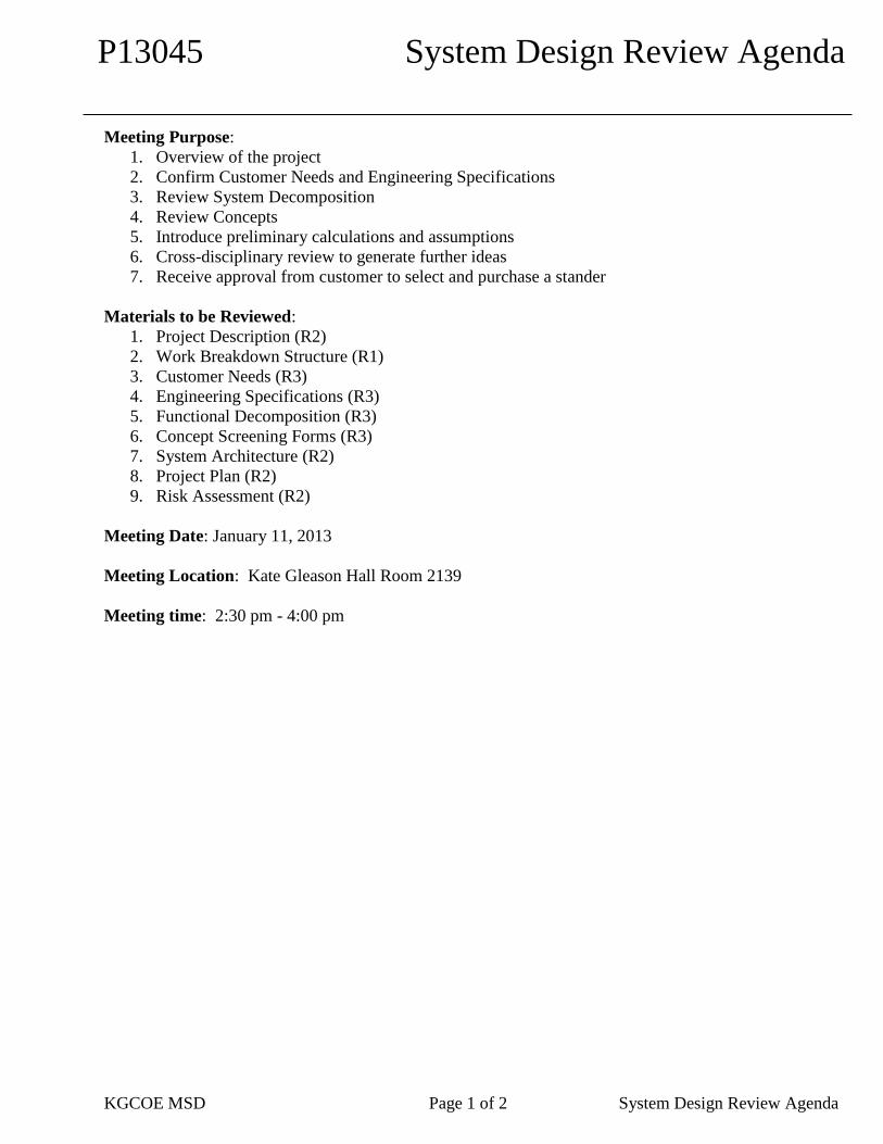
P13045 System Design Review Agenda
KGCOE MSD Page 1 of 2 System Design Review Agenda
Meeting Purpose:
1. Overview of the project
2. Confirm Customer Needs and Engineering Specifications
3. Review System Decomposition
4. Review Concepts
5. Introduce preliminary calculations and assumptions
6. Cross-disciplinary review to generate further ideas
7. Receive approval from customer to select and purchase a stander
Materials to be Reviewed:
1. Project Description (R2)
2. Work Breakdown Structure (R1)
3. Customer Needs (R3)
4. Engineering Specifications (R3)
5. Functional Decomposition (R3)
6. Concept Screening Forms (R3)
7. System Architecture (R2)
8. Project Plan (R2)
9. Risk Assessment (R2)
Meeting Date: January 11, 2013
Meeting Location: Kate Gleason Hall Room 2139
Meeting time: 2:30 pm - 4:00 pm
KGCOE MSD Page 2 of 2 System Design Review Agenda
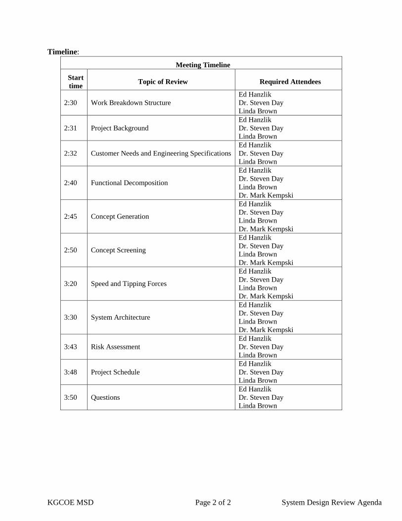
Timeline:
Meeting Timeline
Start
time Topic of Review Required Attendees
2:30 Work Breakdown Structure
Ed Hanzlik
Dr. Steven Day
Linda Brown
2:31 Project Background
Ed Hanzlik
Dr. Steven Day
Linda Brown
2:32 Customer Needs and Engineering Specifications
Ed Hanzlik
Dr. Steven Day
Linda Brown
2:40 Functional Decomposition
Ed Hanzlik
Dr. Steven Day
Linda Brown
Dr. Mark Kempski
2:45 Concept Generation
Ed Hanzlik
Dr. Steven Day
Linda Brown
Dr. Mark Kempski
2:50 Concept Screening
Ed Hanzlik
Dr. Steven Day
Linda Brown
Dr. Mark Kempski
3:20 Speed and Tipping Forces
Ed Hanzlik
Dr. Steven Day
Linda Brown
Dr. Mark Kempski
3:30 System Architecture
Ed Hanzlik
Dr. Steven Day
Linda Brown
Dr. Mark Kempski
3:43 Risk Assessment
Ed Hanzlik
Dr. Steven Day
Linda Brown
3:48 Project Schedule
Ed Hanzlik
Dr. Steven Day
Linda Brown
3:50 Questions
Ed Hanzlik
Dr. Steven Day
Linda Brown

Senior Design Project Data Sheet
Project Description
Project Background: Mobile assist devices are designed to give someone with a disability some independence and feeling of inclusion. In the case of this project, we are trying to mobilize a pediatric standing device so that a disabled child can stand on the same level as their peers and move at the same pace. This project has never been attempted as a senior design project in the past and as out benchmarking has shown, there is no similar device on the market currently. A device that most closely related to this device would be the wheelchair that stands up vertically and turns into a mobile stander.
Problem Statement: The objective of this project is to mobilize a pediatric stander to increase independence and mobility for a child with a disability.
Objectives/Scope: 1. Mobilize a pediatric stander 2. Add no more than 20 pounds to the existing device 3. Incorporate a collision avoidance sensor system 4. Be able to control the device with multiple types of
inputs (joystick, touch screen, etc) 5. Develop a “training” mode for the device 6. Have the ability to remotely control the device
Deliverables: Mobilized Pediatric Stander
System Design
Detailed Design
Expected Project Benefits: Improved mobility and independence of user
Training mode to train the new user on the device
Safe, user friendly controls
Versatile controls to fit various users
Core Team Members: Heather Beam
Thomas Bean
Megan Chapman
Steven Geiger
Kimberly Keating
Strategy & Approach
Assumptions & Constraints: The team will spend a good amount of time studying the mechanics of the existing device and then decide exactly how to mobilize it. This will involve adding a rechargeable power system, motorized wheels, and a control system. The proposed budget is $6000 which was obtained through a grant which seems very reasonable at this point.
Issues & Risks: Components of the device will not be
compatible with each other
Device will not be stable or safe enough for use
Sensors for collision detection will interfere with each other
Project does not get finished on time
Unable to create versatility for use with multiple children
Project goes over budget
Power supply will not be sufficient enough for all components
Unable to incorporate raise/lower feature
Project # Project Name Project Track Project Family
P13045 Mobile Pediatric
Stander
Biomedical Systems
and Technologies
Medical Mobility
Device Engineering Start Term Team Guide Project Sponsor Doc. Revision
2012-W Ed Hanzlik Linda Brown 2

P13045 Work Breakdown Structure Megan Chapman-Project Leader
Construct schedule
Monitor budget
Distribute workload
Assist Heather with Mechanical Engineer work
Heather Beam-Lead Mechanical Engineer Design motorized wheel system
Design mounting mechanisms
Design raise/lower system
Steven Geiger-Lead Controls Engineer
Design user interface and control system
Design Trainer mode
Work with Tom to design Trainer Mode
Kimberly Keating-Systems Engineer Develop safety tests
Help monitor budget
Conduct safety tests
Thomas Bean-Controls Engineer
Design sensor integration
Assist Steve with control system programming
Work with Steve to design Trainer Mode
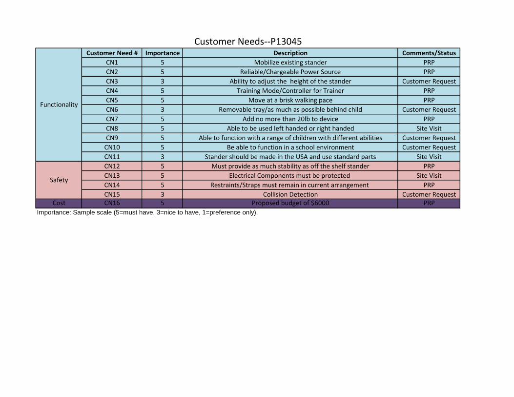
Customer Need # Importance Description Comments/Status
CN1 5 Mobilize existing stander PRP
CN2 5 Reliable/Chargeable Power Source PRP
CN3 3 Ability to adjust the height of the stander Customer Request
CN4 5 Training Mode/Controller for Trainer PRP
CN5 5 Move at a brisk walking pace PRP
CN6 3 Removable tray/as much as possible behind child Customer Request
CN7 5 Add no more than 20lb to device PRP
CN8 5 Able to be used left handed or right handed Site Visit
CN9 5 Able to function with a range of children with different abilities Customer Request
CN10 5 Be able to function in a school environment Customer Request
CN11 3 Stander should be made in the USA and use standard parts Site Visit
CN12 5 Must provide as much stability as off the shelf stander PRP
CN13 5 Electrical Components must be protected Site Visit
CN14 5 Restraints/Straps must remain in current arrangement PRP
CN15 3 Collision Detection Customer RequestCost CN16 5 Proposed budget of $6000 PRP
Customer Needs--P13045
Safety
Importance: Sample scale (5=must have, 3=nice to have, 1=preference only).
Functionality
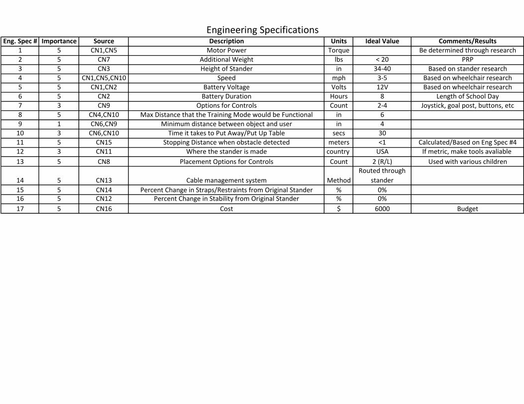
Eng. Spec # Importance Source Description Units Ideal Value Comments/Results
1 5 CN1,CN5 Motor Power Torque Be determined through research
2 5 CN7 Additional Weight lbs < 20 PRP
3 5 CN3 Height of Stander in 34-40 Based on stander research
4 5 CN1,CN5,CN10 Speed mph 3-5 Based on wheelchair research
5 5 CN1,CN2 Battery Voltage Volts 12V Based on wheelchair research
6 5 CN2 Battery Duration Hours 8 Length of School Day
7 3 CN9 Options for Controls Count 2-4 Joystick, goal post, buttons, etc
8 5 CN4,CN10 Max Distance that the Training Mode would be Functional in 6
9 1 CN6,CN9 Minimum distance between object and user in 4
10 3 CN6,CN10 Time it takes to Put Away/Put Up Table secs 30
11 5 CN15 Stopping Distance when obstacle detected meters <1 Calculated/Based on Eng Spec #4
12 3 CN11 Where the stander is made country USA If metric, make tools avaliable
13 5 CN8 Placement Options for Controls Count 2 (R/L) Used with various children
14 5 CN13 Cable management system Method
Routed through
stander
15 5 CN14 Percent Change in Straps/Restraints from Original Stander % 0%16 5 CN12 Percent Change in Stability from Original Stander % 0%
17 5 CN16 Cost $ 6000 Budget
Engineering Specifications

Mo
tor
Po
wer
Ad
dit
ion
al W
eigh
t
Hei
ght
of
Stan
der
Spee
d
Bat
tery
Vo
ltag
e
Bat
tery
Du
rati
on
Op
tio
ns
for
Co
ntr
ols
Max
Dis
tan
ce t
hat
th
e Tr
ain
ing
Mo
de
wo
uld
be
Fun
ctio
nal
Dis
tan
ce o
f Ta
ble
Aw
ay f
rom
Ch
ild
Tim
e it
tak
es t
o P
ut
Aw
ay/P
ut
Up
Tab
le
Sto
pp
ing
Dis
tan
ce w
hen
ob
stac
le d
etec
ted
Wh
ere
the
stan
der
is m
ade
Am
bid
extr
ou
s
Pro
tect
ed e
lect
rica
l co
mp
on
ents
fro
m w
ater
an
d e
xter
nal
fac
tors
Per
cen
t C
han
ge in
Str
aps/
Res
trai
nts
fro
m O
rigi
nal
Sta
nd
er
Per
cen
t C
han
ge in
Sta
bili
ty f
rom
Ori
gin
al S
tan
der
Co
st
Needs 1 2 3 4 5 6 7 8 9 10 11 12 13 14 15 16 17
Mobilize existing stander 1 X X X
Reliable/Chargeable Power Source 2 X X
Ability to adjust the height of the stander 3 X
Training Mode/Controller for Trainer 4 X
Move at a brisk walking pace 5 X X X X
Removable tray/as much as possible behind child 6
Add no more than 20lb to device 7 X
Able to be used left handed or right handed 8 X
Able to function with a range of children with different abilities 9 X X
Be able to function in a school environment 10 X X X
Stander should be made in the USA and use standard parts 11 X
Must provide as much stability as off the shelf stander 12 X
Electrical Components must be protected 13 X
Restraints/Straps must remain in current arrangement 14 X
Collision Detection 15 X
Proposed budget of $6000 16 X
Specifications
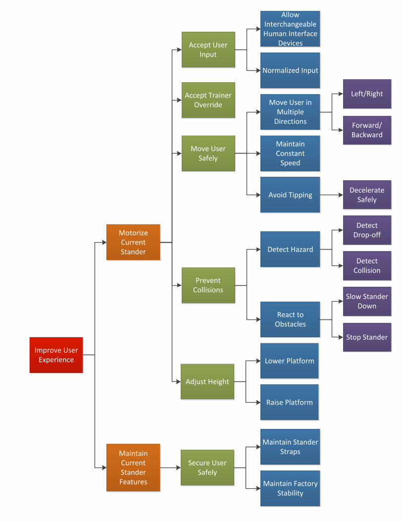
Motorize Current Stander
Accept User Input
Move User Safely
Prevent Collisions
Allow Interchangeable Human Interface
Devices
Normalized Input
Move User in Multiple
Directions
Maintain Constant
Speed
Adjust Height
Raise Platform
Lower Platform
Detect Hazard
React to Obstacles
Left/Right
Forward/Backward
Stop Stander
Slow Stander Down
Accept Trainer Override
Avoid TippingDecelerate
Safely
Detect Collision
Detect Drop-off
Maintain Current Stander Features
Improve User Experience
Secure User Safely
Maintain Stander Straps
Maintain Factory Stability

Concept Generation
Accept User Input
Field Goal
Head Array
Joystick
Push Button Switch
Touch Screen (iPad)
Tongue Switch
Accept Trainer Override
Bluetooth
Wire Connection
Wifi
Move User Safely Motorized Wheels
Treads
Detect Hazard
Infrared Sensor
Cliff Sensor
Laser Rangefinder
Thermal Imaging Sensor
Ultrasonic Sensor
Contact Switch
Adjust Height
Hydraulic Adjustable
Pneumatic Adjustable
Power Adjustable
Stander
Rifton Dynamic Stander
Snug Seat Gecko Standing Frame
Sung Seat Rabbit Mobile Stander
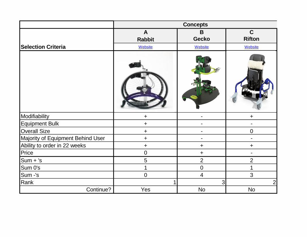
Concepts
A B C
Rabbit Gecko Rifton
Selection Criteria Website Website Website
Modifiability + - +
Equipment Bulk + - -
Overall Size + - 0
Majority of Equipment Behind User + - -
Ability to order in 22 weeks + + +
Price 0 + -
Sum + 's 5 2 2
Sum 0's 1 0 1
Sum -'s 0 4 3
Rank 1 3 2
Continue? Yes No No
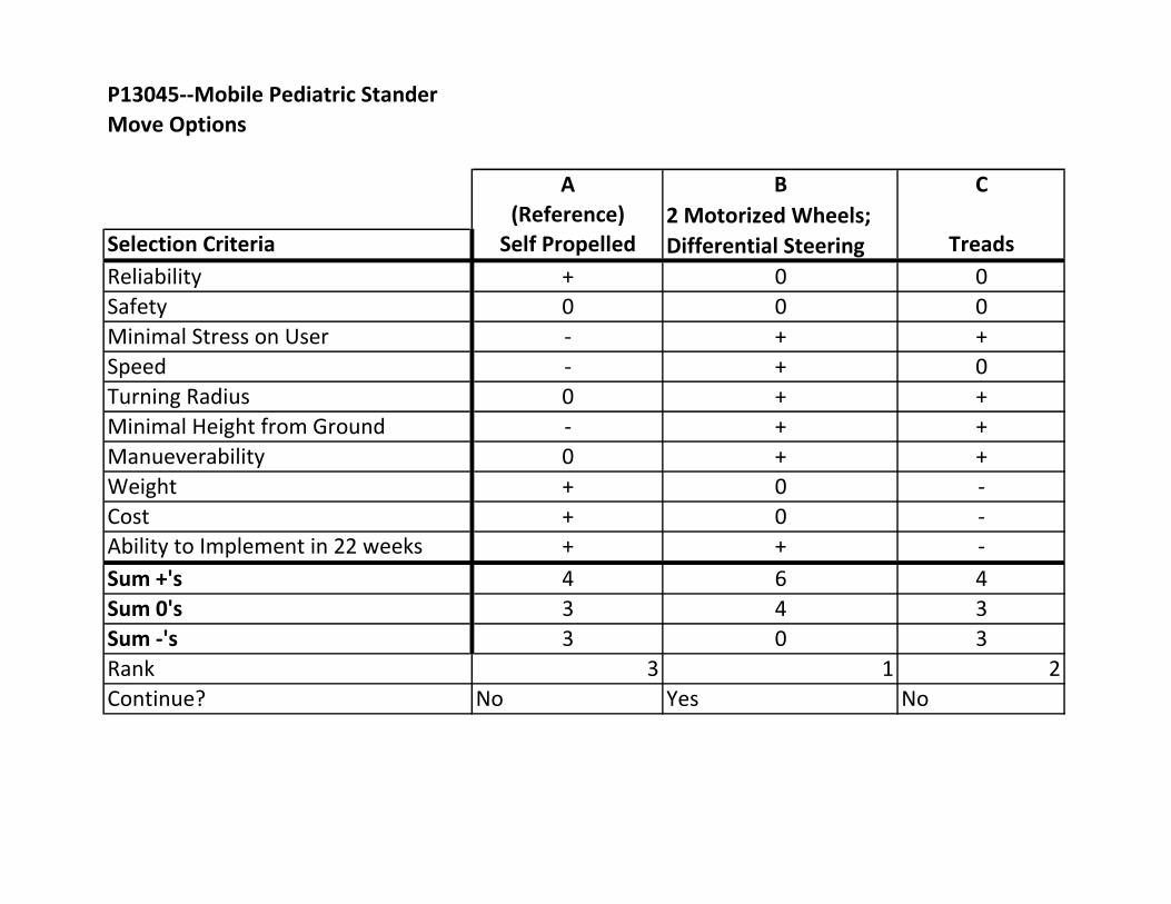
P13045--Mobile Pediatric Stander
Move Options
A B C
(Reference)
Selection Criteria Self Propelled Treads
Reliability + 0 0
Safety 0 0 0
Minimal Stress on User - + +
Speed - + 0
Turning Radius 0 + +
Minimal Height from Ground - + +
Manueverability 0 + +
Weight + 0 -
Cost + 0 -
Ability to Implement in 22 weeks + + -
Sum +'s 4 6 4
Sum 0's 3 4 3
Sum -'s 3 0 3
Rank 3 1 2
Continue? No Yes No
2 Motorized Wheels;
Differential Steering

P13045--Mobile Pediatric Stander
Wheel Placement Options
A B C
(Reference)
Selection Criteria Center Placement Front Placement Rear Placement
Stability 0 0 +
Speed 0 0 0
Turning Radius + 0 -
Obstacle Handling - + 0
Smoothness of Ride 0 + +
Cost 0 0 0
Ability to Implement in 22 weeks + + +
Sum +'s 2 3 3
Sum 0's 4 4 3
Sum -'s 1 0 1
Rank 3 1 2
Continue? No Yes Yes
Source
P13045--Mobile Pediatric Stander
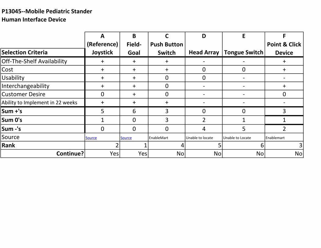
Human Interface Device
A B C D E F
(Reference)
Selection Criteria Joystick Head Array Tongue Switch
Off-The-Shelf Availability + + + - - +
Cost + + + 0 0 +
Usability + + 0 0 - -
Interchangeability + + 0 - - +
Customer Desire 0 + 0 - - 0
Ability to Implement in 22 weeks + + + - - -
Sum +'s 5 6 3 0 0 3
Sum 0's 1 0 3 2 1 1
Sum -'s 0 0 0 4 5 2
Source Source Source EnableMart Unable to locate Unable to Locate Enablemart
Rank 2 1 4 5 6 3
Continue? Yes Yes No No No No
Point & Click
Device
Push Button
Switch
Field-
Goal

P13045--Mobile Pediatric Stander
Raise/Lower System
A B C D
(Reference)
Selection Criteria Manual Hydraulic Pneumatic Motor Driven
Safety + 0 0 0
Easily Adjustable - + + +
Reliability + 0 0 0
Cost + - + +
Time to Adjust - + + +
Wide Height Range 0 + + +
Ability to Implement in 22 weeks + 0 + +
Sum +'s 4 3 5 5
Sum 0's 1 3 2 2
Sum -'s 2 1 0 0
Rank 3 4 1 1
Continue? No No Yes Yes

P13045--Mobile Pediatric Stander
Trainer Mode System
A B C
(Reference)
Selection Criteria Wired Bluetooth Wifi
Portability - + +
Connection Reliability + 0 -
Range - 0 +
Cost + 0 0
Ability to Implement in 22 weeks + + 0
Sum +'s 3 2 2
Sum 0's 0 3 2
Sum -'s 2 0 1
Rank 1 2 3
Continue? Yes Yes No

P13045--Mobile Pediatric Stander
Hazard Detection System
A B C D E F
(Reference)
Selection Criteria
Ultrasonic
Sensor
Laser
Rangefinder
Infrared
Sensor
Thermal Imaging
Sensor
Contact
Switch
Cliff
Sensor
Off-The-Shelf Availability 0 0 0 - 0 +
Cost 0 - - - + +
Minimum Range 0 + - - + 0
Maximum Range 0 + - + - 0
Ease of Interpreting Output 0 0 0 - + +
Ability to Implement in 22 weeks 0 0 0 - 0 +
Sum +'s 0 2 0 1 3 4
Sum 0's 6 3 3 0 2 2
Sum -'s 0 1 3 5 1 0
Rank 2 3 4 6 5 1
Continue? Yes Yes No No Yes Yes

General System Architecture

Proposed System Design
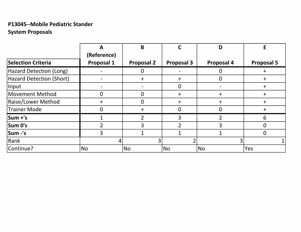
P13045--Mobile Pediatric Stander
System Proposals
A B C D E
(Reference)
Selection Criteria Proposal 1 Proposal 2 Proposal 3 Proposal 4 Proposal 5
Hazard Detection (Long) - 0 - 0 +
Hazard Detection (Short) - + + 0 +
Input - - 0 - +
Movement Method 0 0 + + +
Raise/Lower Method + 0 + + +
Trainer Mode 0 + 0 0 +
Sum +'s 1 2 3 2 6
Sum 0's 2 3 2 3 0
Sum -'s 3 1 1 1 0
Rank 4 3 2 3 1
Continue? No No No No Yes

Number Risk Item Cause Effect Like
liho
od
Seve
rity
Imp
ort
ance
Action to Minimize Risk Owner
Briefly describe the risk
What are the possible
cause(s) of this risk?
What Is the effect on any or
all of the project deliverables
if the cause actually
happens? L*S
What action(s) will you take (and
by when) to prevent, reduce the
impact of, or transfer the risk of
this occurring?
Who is
responsible for
following
through on
mitigation?
1
Components of device will
not be compatible with
each other
Poor planning and
research of parts
Spend more money to order
replacement parts 2 3 6
Communicate with team
members to perform analysis and
research Tom
2
Device is not stable/safe
enough to use
Poor design/engineerng
analysis Unusable device 2 3 6
Conduct multiple trials
throughout the process and
conduct safety tests Kim
3
Sensors will interfere with
each other
Poor design and
implementation of
collision avoidance
system
Device will not move properly
and will have
jerky/inconsistent
movements 2 3 6
Design sensor system and conduct
various tests Tom
4
Customer needs exceed our
engineering abilities
Requested device is too
complex for our abilities
Device will not perform all
desired functions 2 2 4
Communicate with customer and
guide to insure customer needs
are sufficiently met Heather
5
Weight constraints are not
achievable
Poor planning and
execution of design
Device will not meet
customer specifications 2 2 4
Keep track of weight of all
components Steve
6
Project does not get done
on time Poor time management
Poor grade in MSD, unhappy
customer 1 3 3 Create a schedule and stick to it Megan
7
Unable to create versatility
for use with multiple
children
Incompatibility of
components Personalized device 3 1 3
Research a wide variety of
controls Steve
8 Project goes overbudget
Mismanagement of the
budget
The project may not be
completed 1 2 2
Keep track of cost of all
components in a spreadsheet Megan
9
The power supply will not
be sufficient
Poor design/engineerng
analysis
Device will be too heavy to
handle or power output will
not be powerful enough 1 2 2
Perform power analysis when
components are added to ensure
enough power is available Tom
10
Unable to incorporate
raise/lower feature
Too much added weight,
unsafe addition All customer needs not met 2 1 2
Research hydraulics and other
possibilities for customer need Heather
1=low likelihood/severity/importance, 6=high likelihood/severity/importance