Embed Size (px)
Citation preview

107321-P1Rev F, 2/98
Instruction Manual
MKS Type PDR-D-1/PDR-D-2Power Supply
Digital Readout
Six Shattuck RoadAndover, MA 01810-2449(800) 227-8766 or (978) 975-2350
Fax: (978) 975-0093E-mail: [email protected]
Web site: http://www.mksinst.com

WARRANTYType PDR-D-1/PDR-D-2 Equipment
MKS Instruments, Inc. (MKS) warrants that the equipment described above (the
“equipment”) manufactured by MKS shall be free from defects in materials and
workmanship for a period of one year from date of shipment and will for a period of two
years from the date of shipment, correctly perform all date-related operations, including
without limitation accepting data entry, sequencing, sorting, comparing, and reporting,
regardless of the date the operation is performed or the date involved in the operation,
provided that, if the equipment exchanges data or is otherwise used with equipment,
software, or other products of others, such products of others themselves correctly
perform all date-related operations and store and transmit dates and date-related data
in a format compatible with MKS equipment. THIS WARRANTY IS MKS’ SOLE
WARRANTY CONCERNING DATE-RELATED OPERATIONS.
For the period commencing with the date of shipment of this equipment and ending one
year later in the case of defects in materials and workmanship, but two years later in the
case of failure to comply with the date-related operations warranty, MKS will, at its
option, either repair or replace any part which is defective in materials or workmanship
or with respect to the date-related operations warranty without charge to the purchaser.
The foregoing shall constitute the exclusive and sole remedy of the purchaser for any
breach by MKS of this warranty.
The purchaser, before returning any equipment covered by this warranty, which is
asserted to be defective by the purchaser, shall make specific written arrangements
with respect to the responsibility for shipping the equipment and handling any other
incidental charges with the MKS sales representative or distributor from which the
equipment was purchased or, in the case of a direct purchase from MKS, with the MKShome office in Andover, Massachusetts, USA.
This warranty does not apply to any equipment which has not been installed and used
in accordance with the specifications recommended by MKS for the proper and normal
use of the equipment. MKS shall not be liable under any circumstances for indirect,
special, consequential, or incidental damages in connection with, or arising out of, the
sale, performance, or use of the equipment covered by this warranty.
MKS recommends that all MKS pressure and flow products be calibrated periodically
(typically every 6 to 12 months) to ensure accurate readings. When a product is
returned to MKS for this periodic re-calibration it is considered normal preventative
maintenance not covered by any warranty.
THIS WARRANTY IS IN LIEU OF ALL OTHER RELEVANT WARRANTIES,
EXPRESSED OR IMPLIED, INCLUDING THE IMPLIED WARRANTY OF
MERCHANTABILITY AND THE IMPLIED WARRANTY OF FITNESS FOR A
PARTICULAR PURPOSE, AND ANY WARRANTY AGAINST INFRINGEMENT OF
ANY PATENT.
11-98 107321-P1

107321-P1Rev F, 2/98
MKS Type PDR-D-1/PDR-D-2Power Supply
Digital Readout

Copyright © 1998 by MKS Instruments, Inc.
All rights reserved. No part of this work may be reproduced or transmitted in any form or byany means, electronic or mechanical, including photocopying and recording, or by anyinformation storage or retrieval system, except as may be expressly permitted in writing by MKSInstruments, Inc.
Printed in the United States of America
Baratron is a registered trademark of MKS Instruments, Inc., Andover, MA
Table of Contents
iii
Table of Contents
Safety Information.................................................................................................................. 1
Symbols Used in This Instruction Manual.................................................................. 1
Symbols Found on the Unit ....................................................................................... 2
Safety Procedures and Precautions ............................................................................. 3
Sicherheitshinweise................................................................................................................ 5
In dieser Betriebsanleitung vorkommende Symbole ................................................... 5
Am Gerät angebrachte Symbole................................................................................. 6
Sicherheitsvorschriften und Vorsichtsmaßnahmen...................................................... 7
Informations relatives à la sécurité.......................................................................................... 9
Symboles utilisés dans ce manuel d'utilisation ........................................................... 9
Symboles apparaissant sur l'appareil .......................................................................... 10
Mesures de sécurité et mises en garde ........................................................................ 11
Información sobre seguridad................................................................................................... 13
Símbolos usados en el manual de instrucciones.......................................................... 13
Símbolos que aparecen en la unidad........................................................................... 14
Procedimientos y precauciones de seguridad .............................................................. 15
Chapter One: General Information......................................................................................... 17
Introduction ............................................................................................................... 17
How This Manual is Organized.................................................................................. 18
Customer Support ...................................................................................................... 19
Chapter Two: Installation ...................................................................................................... 21
How To Unpack the Type PDR-D Unit...................................................................... 21
Unpacking Checklist ..................................................................................... 21
Interface Cables ......................................................................................................... 22
Generic Shielded Cable Description .............................................................. 22
Cable Connections ........................................................................................ 23
Product Location and Requirements........................................................................... 23
Table of Contents
iv
Operating Environmental Requirements.........................................................23
Electrical Information.................................................................................................23
Grounds.........................................................................................................23
Setup..........................................................................................................................24
Chapter Three: Overview .......................................................................................................25
Front Panel Controls ..................................................................................................25
Zero Control ..................................................................................................25
How To Access Front Panel Controls.............................................................26
Span Adjust ...................................................................................................26
Decimal Point Selector ..................................................................................27
Rear Panel Controls....................................................................................................28
Pressure Transducer Connector ......................................................................28
Fuse Holder ...................................................................................................28
Line Cord ......................................................................................................29
Chapter Four: Operation ........................................................................................................31
General Information ...................................................................................................31
Theory of Operation ...................................................................................................31
Pressure Signal ..............................................................................................31
Overrange Comparator...................................................................................31
Display and Decimal Selector ........................................................................31
Power Supplies ..............................................................................................32
Chapter Five: Maintenance and Troubleshooting....................................................................33
General Information ...................................................................................................33
How To Clean the Unit ..................................................................................33
Fault Isolation ............................................................................................................33
Appendix A: Product Specifications.......................................................................................35
Electrical Specifications .............................................................................................35
Performance Specifications ........................................................................................35
Physical Specifications...............................................................................................35
Environmental Specifications .....................................................................................35
Appendix B: Model Code Explanation...................................................................................37

Table of Contents
v
Model Code............................................................................................................... 37
Index...................................................................................................................................... 39

Table of Contents
vi
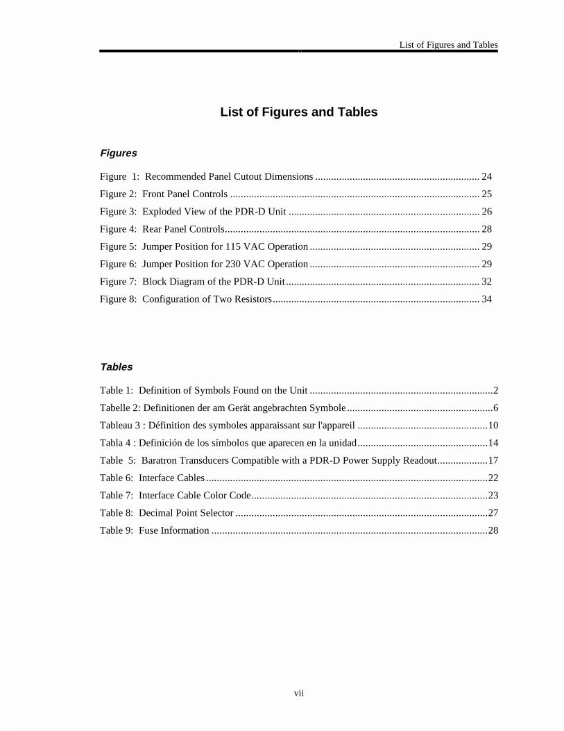
List of Figures and Tables
vii
List of Figures and Tables
Figures
Figure 1: Recommended Panel Cutout Dimensions .............................................................. 24
Figure 2: Front Panel Controls .............................................................................................. 25
Figure 3: Exploded View of the PDR-D Unit ........................................................................ 26
Figure 4: Rear Panel Controls................................................................................................ 28
Figure 5: Jumper Position for 115 VAC Operation ................................................................ 29
Figure 6: Jumper Position for 230 VAC Operation ................................................................ 29
Figure 7: Block Diagram of the PDR-D Unit ......................................................................... 32
Figure 8: Configuration of Two Resistors.............................................................................. 34
Tables
Table 1: Definition of Symbols Found on the Unit .....................................................................2
Tabelle 2: Definitionen der am Gerät angebrachten Symbole.......................................................6
Tableau 3 : Définition des symboles apparaissant sur l'appareil .................................................10
Tabla 4 : Definición de los símbolos que aparecen en la unidad.................................................14
Table 5: Baratron Transducers Compatible with a PDR-D Power Supply Readout...................17
Table 6: Interface Cables ..........................................................................................................22
Table 7: Interface Cable Color Code.........................................................................................23
Table 8: Decimal Point Selector ...............................................................................................27
Table 9: Fuse Information ........................................................................................................28

List of Figures and Tables
viii
Safety Information Symbols Used in This Instruction Manual
1
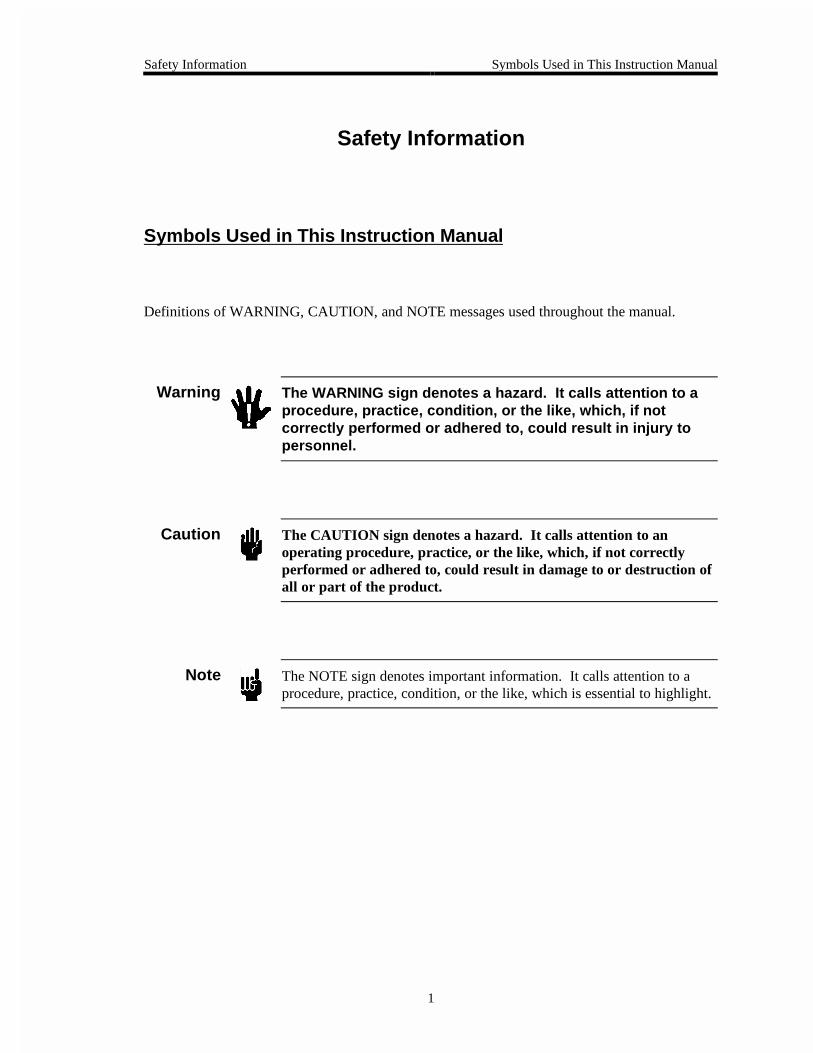
Safety Information
Symbols Used in This Instruction Manual
Definitions of WARNING, CAUTION, and NOTE messages used throughout the manual.
Warning The WARNING sign denotes a hazard. It calls attention to aprocedure, practice, condition, or the like, which, if notcorrectly performed or adhered to, could result in injury topersonnel.
Caution The CAUTION sign denotes a hazard. It calls attention to anoperating procedure, practice, or the like, which, if not correctlyperformed or adhered to, could result in damage to or destruction ofall or part of the product.
Note The NOTE sign denotes important information. It calls attention to aprocedure, practice, condition, or the like, which is essential to highlight.
Symbols Found on the Unit Safety Information
2
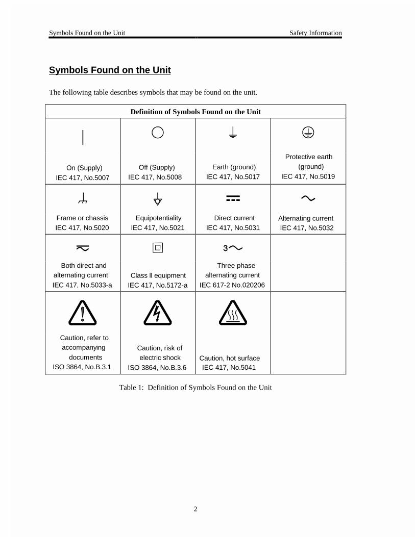
Symbols Found on the Unit
The following table describes symbols that may be found on the unit.
Definition of Symbols Found on the Unit
|
On (Supply) IEC 417, No.5007
Off (Supply)IEC 417, No.5008
Earth (ground) IEC 417, No.5017
Protective earth (ground)
IEC 417, No.5019
Frame or chassis IEC 417, No.5020
Equipotentiality IEC 417, No.5021
Direct current IEC 417, No.5031
Alternating currentIEC 417, No.5032
Both direct andalternating current
IEC 417, No.5033-aClass ll equipment
IEC 417, No.5172-a
Three phasealternating current
IEC 617-2 No.020206
Caution, refer toaccompanying
documentsISO 3864, No.B.3.1
Caution, risk ofelectric shock
ISO 3864, No.B.3.6Caution, hot surfaceIEC 417, No.5041
Table 1: Definition of Symbols Found on the Unit
Safety Information Safety Procedures and Precautions
3
Safety Procedures and Precautions
The following general safety precautions must be observed during all phases of operation of thisinstrument. Failure to comply with these precautions or with specific warnings elsewhere inthis manual violates safety standards of intended use of the instrument and may impair theprotection provided by the equipment. MKS Instruments, Inc. assumes no liability for thecustomer’s failure to comply with these requirements.
DO NOT SUBSTITUTE PARTS OR MODIFY INSTRUMENT
Do not install substitute parts or perform any unauthorized modification to the instrument.Return the instrument to an MKS Calibration and Service Center for service and repair to ensurethat all safety features are maintained.
SERVICE BY QUALIFIED PERSONNEL ONLY
Operating personnel must not remove instrument covers. Component replacement and internaladjustments must be made by qualified service personnel only.
GROUNDING THE PRODUCT
This product is grounded through the grounding conductor of the power cord. To avoid electricalshock, plug the power cord into a properly wired receptacle before connecting it to the productinput or output terminals. A protective ground connection by way of the grounding conductor inthe power cord is essential for safe operation.
DANGER ARISING FROM LOSS OF GROUND
Upon loss of the protective-ground connection, all accessible conductive parts (including knobsand controls that may appear to be insulating) can render an electrical shock.
GROUND AND USE PROPER ELECTRICAL FITTINGS
Dangerous voltages are contained within this instrument. All electrical fittings and cables mustbe of the type specified, and in good condition. All electrical fittings must be properly connectedand grounded.
USE THE PROPER POWER CORD
Use only a power cord that is in good condition and which meets the input power requirementsspecified in the manual.
Use only a detachable cord set with conductors that have a cross-sectional area equal to or greaterthan 0.75 mm2. The power cable should be approved by a qualified agency such as VDE,Semko, or SEV.

Safety Procedures and Precautions Safety Information
4
USE THE PROPER POWER SOURCE
This product is intended to operate from a power source that does not apply more voltagebetween the supply conductors, or between either of the supply conductors and ground, than thatspecified in the manual.
USE THE PROPER FUSE
Use only a fuse of the correct type, voltage rating, and current rating, as specified for yourproduct.
DO NOT OPERATE IN EXPLOSIVE ATMOSPHERES
To avoid explosion, do not operate this product in an explosive environment unless it has beenspecifically certified for such operation.
HIGH VOLTAGE DANGER
High voltage is present in the cable, and in the sensor when the controller is turned on.

Sicherheitshinweise In dieser Betriebsanleitung vorkommende Symbole
5
Sicherheitshinweise
In dieser Betriebsanleitung vorkommende Symbole
Definition der mit WARNUNG!, VORSICHT! und HINWEIS überschriebenen Abschnitte indieser Betriebsanleitung.
Warnung! &CU 5[ODQN 9#4070) YGKUV CWH GKPG )GHCJTGPSWGNNG JKP 'U
OCEJV CWH GKPGP #TDGKVUCDNCWH GKPG #TDGKVUYGKUG GKPGP
<WUVCPF QFGT GKPG UQPUVKIG )GIGDGPJGKV CWHOGTMUCO FGTGP
WPUCEJIGO·G #WUHÒJTWPI D\Y WPIGPÒIGPFG
$GTÒEMUKEJVKIWPI \W -ÌTRGTXGTNGV\WPI HÒJTGP MCPP
8QTUKEJV Das Symbol VORSICHT! weist auf eine Gefahrenquelle hin. Esmacht auf einen Bedienungsablauf, eine Arbeitsweise oder einesonstige Gegebenheit aufmerksam, deren unsachgemäße Ausführungbzw. Ungenügende Berücksichtigung zu einer Beschädigung oderZerstörung des Produkts oder von Teilen des Produkts führen kann.
*KPYGKU Das Symbol HINWEIS weist auf eine wichtige Mitteilung hin, die aufeinen Arbeitsablauf, eine Arbeitsweise, einen Zustand oder eine sonstigeGegebenheit von besonderer Wichtigkeit aufmerksam macht.
Am Gerät angebrachte Symbole Sicherheitshinweise
6
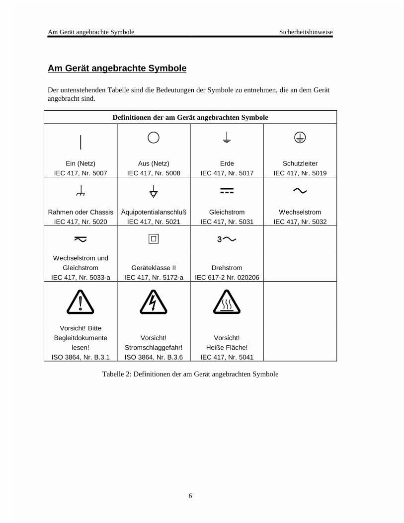
Am Gerät angebrachte Symbole
Der untenstehenden Tabelle sind die Bedeutungen der Symbole zu entnehmen, die an dem Gerätangebracht sind.
Definitionen der am Gerät angebrachten Symbole
|Ein (Netz)
IEC 417, Nr. 5007
Aus (Netz)
IEC 417, Nr. 5008
Erde
IEC 417, Nr. 5017
Schutzleiter
IEC 417, Nr. 5019
Rahmen oder Chassis
IEC 417, Nr. 5020
Äquipotentialanschluß
IEC 417, Nr. 5021
Gleichstrom
IEC 417, Nr. 5031
Wechselstrom
IEC 417, Nr. 5032
Wechselstrom und
Gleichstrom
IEC 417, Nr. 5033-a
Geräteklasse II
IEC 417, Nr. 5172-a
Drehstrom
IEC 617-2 Nr. 020206
Vorsicht! Bitte
Begleitdokumente
lesen!
ISO 3864, Nr. B.3.1
Vorsicht!
Stromschlaggefahr!
ISO 3864, Nr. B.3.6
Vorsicht!
Heiße Fläche!
IEC 417, Nr. 5041
Tabelle 2: Definitionen der am Gerät angebrachten Symbole

Sicherheitshinweise Sicherheitsvorschriften und Vorsichtsmaßnahmen
7
Sicherheitsvorschriften und Vorsichtsmaßnahmen
Die untenstehenden allgemeinen Sicherheitsvorschriften sind bei allen Betriebs-phasendieses Instruments zu befolgen. Jede Mißachtung dieser Sicherheits-vorschriften odersonstiger spezifischer Warnhinweise in dieser Betriebsanleitung stellt eineZuwiderhandlung der für dieses Instrument geltenden Sicherheits-standards dar und kanndie an diesem Instrument vorgesehenen Schutzvor-richtungen unwirksam machen. MKSInstruments, Inc. haftet nicht für eine Mißachtung dieser Sicherheitsvorschriften seitensdes Kunden.
Keine Teile austauschen und keine Veränderungen vornehmen!
Bauen Sie in das Instrument keine Ersatzteile ein, und nehmen Sie keine eigenmächtigenÄnderungen am Gerät vor! Schicken Sie das Instrument zu Wartungs- und Reparatur-zwecken aneinen MKS-Kalibrierungs- und -Kundendienst ein! Dadurch wird sicher-gestellt, daß alleSicherheitseinrichtungen voll funktionsfähig bleiben.
Wartung nur durch qualifizierte Fachleute!
Das Gehäuse des Instruments darf vom Bedienpersonal nicht geöffnet werden. Das Auswechselnvon Bauteilen und das Vornehmen von internen Einstellungen ist nur von qualifiziertenFachleuten durchzuführen.
Produkt erden!
Dieses Produkt ist mit einer Erdleitung und einem Schutzkontakt am Netzstecker versehen. Umder Gefahr eines elektrischen Schlages vorzubeugen, ist das Netzkabel an einer vorschriftsmäßiggeerdeten Schutzkontaktsteckdose anzuschließen, bevor es an den Eingangs- bzw.Ausgangsklemmen des Produkts angeschlossen wird. Das Instrument kann nur sicher betriebenwerden, wenn es über den Erdleiter des Netzkabels und einen Schutzkontakt geerdet wird.
Gefährdung durch Verlust der Schutzerdung!
Geht die Verbindung zum Schutzleiter verloren, besteht an sämtlichen zugänglichen Teilen ausstromleitendem Material die Gefahr eines elektrischen Schlages. Dies gilt auch für Knöpfe undandere Bedienelemente, die dem Anschein nach isoliert sind.
Sicherheitsvorschriften und Vorsichtsmaßnahmen Sicherheitshinweise
8
Erdung und Verwendung geeigneter elektrischer Armaturen!
In diesem Instrument liegen gefährliche Spannungen an. Alle verwendeten elektrischenArmaturen und Kabel müssen dem angegebenen Typ entsprechen und sich in einwand-freiemZustand befinden. Alle elektrischen Armaturen sind vorschriftsmäßig anzubringen und zu erden.
Richtiges Netzkabel verwenden!
Das verwendete Netzkabel muß sich in einwandfreiem Zustand befinden und den in derBetriebsanleitung enthaltenen Anschlußwerten entsprechen.
Das Netzkabel muß abnehmbar sein. Der Querschnitt der einzelnen Leiter darf nicht weniger als0,75 mm2 betragen. Das Netzkabel sollte einen Prüfvermerk einer zuständigen Prüfstelle tragen,z.B. VDE, Semko oder SEV.
Richtige Stromquelle verwenden!
Dieses Produkt ist für eine Stromquelle vorgesehen, bei der die zwischen den Leitern bzw.zwischen jedem der Leiter und dem Masseleiter anliegende Spannung den in dieserBetriebsanleitung angegebenen Wert nicht überschreitet.
Richtige Sicherung benutzen!
Es ist eine Sicherung zu verwenden, deren Typ, Nennspannung und Nennstromstärke denAngaben für dieses Produkt entsprechen.
Gerät nicht in explosiver Atmosphäre benutzen!
Um der Gefahr einer Explosion vorzubeugen, darf dieses Gerät nicht in der Nähe explosiverStoffe eingesetzt werden, sofern es nicht ausdrücklich für diesen Zweck zertifiziert worden ist.
Hochspannungsgefahr!
Bei eingeschaltetem Steuerteil liegt im Kabel und im Sensor Hochspannung an.
Informations relatives à la sécurité Symboles utilisés dans ce manuel d'utilisation
9
Informations relatives à la sécurité
Symboles utilisés dans ce manuel d'utilisation
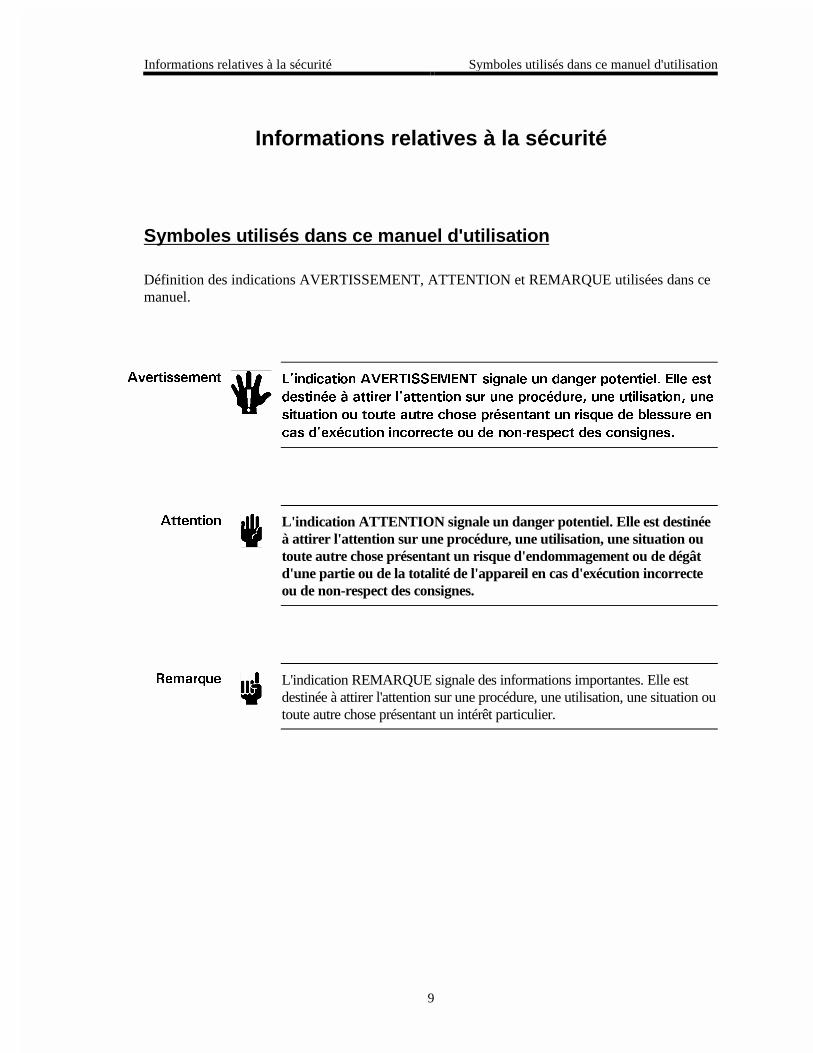
Définition des indications AVERTISSEMENT, ATTENTION et REMARQUE utilisées dans cemanuel.
#XGTVKUUGOGPV .KPFKECVKQP #8'46+55'/'06 UKIPCNG WP FCPIGT RQVGPVKGN 'NNG GUV
FGUVKP¾G ¯ CVVKTGT NCVVGPVKQP UWT WPG RTQE¾FWTG WPG WVKNKUCVKQP WPG
UKVWCVKQP QW VQWVG CWVTG EJQUG RT¾UGPVCPV WP TKUSWG FG DNGUUWTG GP
ECU FGZ¾EWVKQP KPEQTTGEVG QW FG PQPTGURGEV FGU EQPUKIPGU
#VVGPVKQP L'indication ATTENTION signale un danger potentiel. Elle est destinéeà attirer l'attention sur une procédure, une utilisation, une situation outoute autre chose présentant un risque d'endommagement ou de dégâtd'une partie ou de la totalité de l'appareil en cas d'exécution incorrecteou de non-respect des consignes.
4GOCTSWG L'indication REMARQUE signale des informations importantes. Elle estdestinée à attirer l'attention sur une procédure, une utilisation, une situation outoute autre chose présentant un intérêt particulier.
Symboles apparaissant sur l'appareil Informations relatives à la sécurité
10
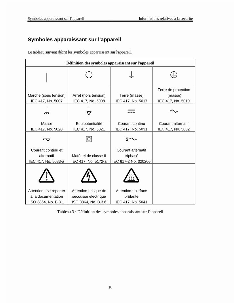
Symboles apparaissant sur l'appareil
Le tableau suivant décrit les symboles apparaissant sur l'appareil.
Définition des symboles apparaissant sur l'appareil
|
Marche (sous tension)
IEC 417, No. 5007
Arrêt (hors tension)
IEC 417, No. 5008
Terre (masse)
IEC 417, No. 5017
Terre de protection
(masse)
IEC 417, No. 5019
Masse
IEC 417, No. 5020
Equipotentialité
IEC 417, No. 5021
Courant continu
IEC 417, No. 5031
Courant alternatif
IEC 417, No. 5032
Courant continu et
alternatif
IEC 417, No. 5033-a
Matériel de classe II
IEC 417, No. 5172-a
Courant alternatif
triphasé
IEC 617-2 No. 020206
Attention : se reporter
à la documentation
ISO 3864, No. B.3.1
Attention : risque de
secousse électrique
ISO 3864, No. B.3.6
Attention : surface
brûlante
IEC 417, No. 5041
Tableau 3 : Définition des symboles apparaissant sur l'appareil
Informations relatives à la sécurité Mesures de sécurité et mises en garde
11
Mesures de sécurité et mises en garde
Prendre toutes les précautions générales suivantes pendant toutes les phases d'utilisation de cetappareil. Le non-respect de ces précautions ou des avertissements contenus dans ce manuelentraîne une violation des normes de sécurité relatives à l'utilisation de l'appareil et le risque deréduire le niveau de protection fourni par l'appareil. MKS Instruments, Inc. ne prend aucuneresponsabilité pour les conséquences de tout non-respect des consignes de la part de ses clients.
NE PAS SUBSTITUER DES PIÈCES OU MODIFIER L'APPAREIL
Ne pas utiliser de pièces détachées autres que celles vendues par MKS Instruments, Inc. oumodifier l'appareil sans l'autorisation préalable de MKS Instruments, Inc. Renvoyer l'appareil àun centre d'étalonnage et de dépannage MKS pour tout dépannage ou réparation afin de s'assurerque tous les dispositifs de sécurité sont maintenus.
DÉPANNAGE EFFECTUÉ UNIQUEMENT PAR UN PERSONNEL QUALIFIÉ
L'opérateur de l'appareil ne doit pas enlever le capot de l'appareil. Le remplacement descomposants et les réglages internes doivent être effectués uniquement par un personneld'entretien qualifié.
MISE À LA TERRE DE L'APPAREIL
Cet appareil est mis à la terre à l'aide du fil de terre du cordon d'alimentation. Pour éviter toutrisque de secousse électrique, brancher le cordon d'alimentation sur une prise de courantcorrectement câblée avant de le brancher sur les bornes d'entrée ou de sortie de l'appareil. Unemise à la terre de protection à l'aide du fil de terre du cordon d'alimentation est indispensablepour une utilisation sans danger de l'appareil.
DANGER LIÉ À UN DÉFAUT DE TERRE
En cas de défaut de terre, toutes les pièces conductrices accessibles (y compris les boutons decommande ou de réglage qui semblent être isolés) peuvent être source d'une secousse électrique.
MISE À LA TERRE ET UTILISATION CORRECTE D'ACCESSOIRES ÉLECTRIQUES
Des tensions dangereuses existent à l'intérieur de l'appareil. Tous les accessoires et les câblesélectriques doivent être conformes au type spécifié et être en bon état. Tous les accessoiresélectriques doivent être correctement connectés et mis à la terre.
Mesures de sécurité et mises en garde Informations relatives à la sécurité
12
UTILISATION D'UN CORDON D'ALIMENTATION APPROPRIÉ
Utiliser uniquement un cordon d'alimentation en bon état et conforme aux exigences de puissanced'entrée spécifiées dans le manuel.
Utiliser uniquement un cordon d'alimentation amovible avec des conducteurs dont la section estégale ou supérieure à 0,75 mm2. Le cordon d'alimentation doit être approuvé par un organismecompétent tel que VDE, Semko ou SEV.
UTILISATION D'UNE ALIMENTATION APPROPRIÉE
Cet appareil est conçu pour fonctionner en s'alimentant sur une source de courant électriquen'appliquant pas une tension entre les conducteurs d'alimentation, ou entre les conducteursd'alimentation et le conducteur de terre, supérieure à celle spécifiée dans le manuel.
UTILISATION D'UN FUSIBLE APPROPRIÉ
Utiliser uniquement un fusible conforme au type, à la tension nominale et au courant nominalspécifiés pour l'appareil.
NE PAS UTILISER DANS UNE ATMOSPHÈRE EXPLOSIVE
Pour éviter tout risque d'explosion, ne pas utiliser l'appareil dans une atmosphère explosive àmoins qu'il n'ait été approuvé pour une telle utilisation.
DANGER DE HAUTE TENSION
Une haute tension est présente dans le câble et dans le capteur lorsque le contrôleur est soustension.
Información sobre seguridad Símbolos usados en el manual de instrucciones
13
Información sobre seguridad
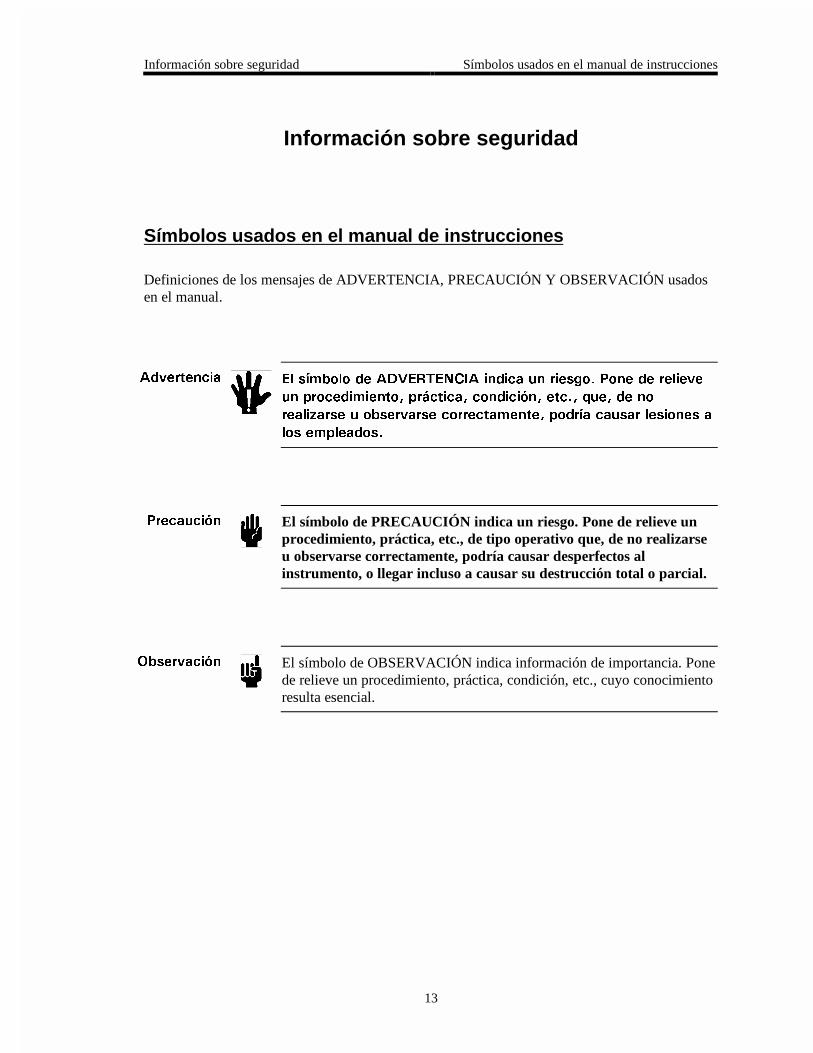
Símbolos usados en el manual de instrucciones
Definiciones de los mensajes de ADVERTENCIA, PRECAUCIÓN Y OBSERVACIÓN usadosen el manual.
#FXGTVGPEKC 'N UÃODQNQ FG #&8'46'0%+# KPFKEC WP TKGUIQ 2QPG FG TGNKGXG
WP RTQEGFKOKGPVQ RT±EVKEC EQPFKEKÉP GVE SWG FG PQ
TGCNK\CTUG W QDUGTXCTUG EQTTGEVCOGPVG RQFTÃC ECWUCT NGUKQPGU C
NQU GORNGCFQU
2TGECWEKÉP El símbolo de PRECAUCIÓN indica un riesgo. Pone de relieve unprocedimiento, práctica, etc., de tipo operativo que, de no realizarseu observarse correctamente, podría causar desperfectos alinstrumento, o llegar incluso a causar su destrucción total o parcial.
1DUGTXCEKÉP El símbolo de OBSERVACIÓN indica información de importancia. Ponede relieve un procedimiento, práctica, condición, etc., cuyo conocimientoresulta esencial.
Símbolos que aparecen en la unidad Información sobre seguridad
14
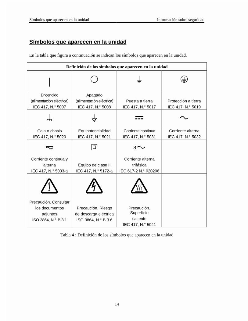
Símbolos que aparecen en la unidad
En la tabla que figura a continuación se indican los símbolos que aparecen en la unidad.
Definición de los símbolos que aparecen en la unidad
|Encendido
(alimentación eléctrica)
IEC 417, N.° 5007
Apagado
(alimentación eléctrica)
IEC 417, N.° 5008
Puesta a tierra
IEC 417, N.° 5017
Protección a tierra
IEC 417, N.° 5019
Caja o chasis
IEC 417, N.° 5020
Equipotencialidad
IEC 417, N.° 5021
Corriente continua
IEC 417, N.° 5031
Corriente alterna
IEC 417, N.° 5032
Corriente continua y
alterna
IEC 417, N.° 5033-a
Equipo de clase II
IEC 417, N.° 5172-a
Corriente alterna
trifásica
IEC 617-2 N.° 020206
Precaución. Consultar
los documentos
adjuntos
ISO 3864, N.° B.3.1
Precaución. Riesgo
de descarga eléctrica
ISO 3864, N.° B.3.6
Precaución.Superficie
caliente
IEC 417, N.° 5041
Tabla 4 : Definición de los símbolos que aparecen en la unidad
Información sobre seguridad Procedimientos y precauciones de seguridad
15
Procedimientos y precauciones de seguridad
Las precauciones generales de seguridad que figuran a continuación deben observarsedurante todas las fases de funcionamiento del presente instrumento. La no observancia dedichas precauciones, o de las advertencias específicas a las que se hace referencia en elmanual, contraviene las normas de seguridad referentes al uso previsto del instrumento ypodría impedir la protección que proporciona el instrumento. MKS Instruments, Inc., noasume responsabilidad alguna en caso de que el cliente haga caso omiso de estosrequerimientos.
NO UTILIZAR PIEZAS NO ORIGINALES NI MODIFICAR EL INSTRUMENTO
No se debe instalar piezas que no sean originales ni modificar el instrumento sin autorización.Para garantizar que las prestaciones de seguridad se observen en todo momento, enviar elinstrumento al Centro de servicio y calibración de MKS cuando sea necesaria su reparación yservicio de mantenimiento.
REPARACIONES EFECTUADAS ÚNICAMENTE POR TÉCNICOS ESPECIALIZADOS
Los operarios no deben retirar las cubiertas del instrumento. El cambio de piezas y los reajustesinternos deben efectuarlos únicamente técnicos especializados.
PUESTA A TIERRA DEL INSTRUMENTO
Este instrumento está puesto a tierra por medio del conductor de tierra del cable eléctrico. Paraevitar descargas eléctricas, enchufar el cable eléctrico en una toma debidamente instalada, antesde conectarlo a las terminales de entrada o salida del instrumento. Para garantizar el uso sinriesgos del instrumento resulta esencial que se encuentre puesto a tierra por medio del conductorde tierra del cable eléctrico.
PELIGRO POR PÉRDIDA DE LA PUESTA A TIERRA
Si se pierde la conexión protectora de puesta a tierra, todas las piezas conductoras a las que setiene acceso (incluidos los botones y mandos que pudieran parecer estar aislados) podríanproducir descargar eléctricas.
PUESTA A TIERRA Y USO DE ACCESORIOS ELÉCTRICOS ADECUADOS
Este instrumento funciona con voltajes peligrosos. Todos los accesorios y cables eléctricos debenser del tipo especificado y mantenerse en buenas condiciones. Todos los accesorios eléctricosdeben estar conectados y puestos a tierra del modo adecuado.
Procedimientos y precauciones de seguridad Información sobre seguridad
16
USAR EL CABLE ELÉCTRICO ADECUADO
Usar únicamente un cable eléctrico que se encuentre en buenas condiciones y que cumpla losrequisitos de alimentación de entrada indicados en el manual.
Usar únicamente un cable desmontable instalado con conductores que tengan un área de seccióntransversal equivalente o superior a 0,75mm². El cable eléctrico debe estar aprobado por unaentidad autorizada como, por ejemplo, VDE, Semko o SEV.
USAR LA FUENTE DE ALIMENTACIÓN ELÉCTRICA ADECUADA
Este instrumento debe funcionar a partir de una fuente de alimentación eléctrica que no apliquemás voltaje entre los conductores de suministro, o entre uno de los conductores de suministro yla puesta a tierra, que el que se especifica en el manual.
USAR EL FUSIBLE ADECUADO
Usar únicamente un fusible del tipo, clase de voltaje y de corriente adecuados, según lo que seespecifica para el instrumento.
EVITAR SU USO EN ENTORNOS EXPLOSIVOS
Para evitar el riesgo de explosión, no usar este instrumento o en un entorno explosivo, a no serque haya sido certificado para tal uso.
PELIGRO POR ALTO VOLTAJE
Cuando el controlador está encendido, se registra alto voltaje en el cable y en el sensor.
Chapter One: General Information Introduction
17
Chapter One: General Information
Introduction
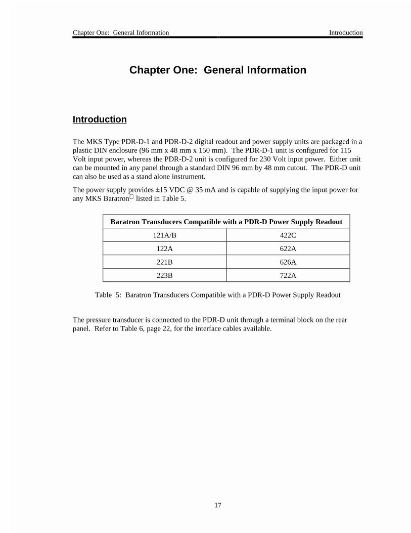
The MKS Type PDR-D-1 and PDR-D-2 digital readout and power supply units are packaged in aplastic DIN enclosure (96 mm x 48 mm x 150 mm). The PDR-D-1 unit is configured for 115Volt input power, whereas the PDR-D-2 unit is configured for 230 Volt input power. Either unitcan be mounted in any panel through a standard DIN 96 mm by 48 mm cutout. The PDR-D unitcan also be used as a stand alone instrument.
The power supply provides ±15 VDC @ 35 mA and is capable of supplying the input power forany MKS Baratron listed in Table 5.
Baratron Transducers Compatible with a PDR-D Power Supply Readout
121A/B 422C
122A 622A
221B 626A
223B 722A
Table 5: Baratron Transducers Compatible with a PDR-D Power Supply Readout
The pressure transducer is connected to the PDR-D unit through a terminal block on the rearpanel. Refer to Table 6, page 22, for the interface cables available.
How This Manual is Organized Chapter One: General Information
18
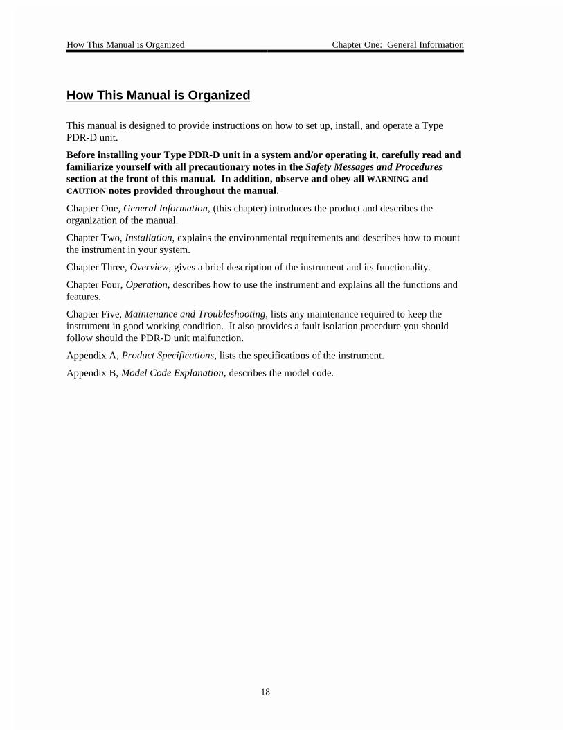
How This Manual is Organized
This manual is designed to provide instructions on how to set up, install, and operate a TypePDR-D unit.
Before installing your Type PDR-D unit in a system and/or operating it, carefully read andfamiliarize yourself with all precautionary notes in the Safety Messages and Proceduressection at the front of this manual. In addition, observe and obey all WARNING andCAUTION notes provided throughout the manual.
Chapter One, General Information, (this chapter) introduces the product and describes theorganization of the manual.
Chapter Two, Installation, explains the environmental requirements and describes how to mountthe instrument in your system.
Chapter Three, Overview, gives a brief description of the instrument and its functionality.
Chapter Four, Operation, describes how to use the instrument and explains all the functions andfeatures.
Chapter Five, Maintenance and Troubleshooting, lists any maintenance required to keep theinstrument in good working condition. It also provides a fault isolation procedure you shouldfollow should the PDR-D unit malfunction.
Appendix A, Product Specifications, lists the specifications of the instrument.
Appendix B, Model Code Explanation, describes the model code.
Chapter One: General Information Customer Support
19
Customer Support
Standard maintenance and repair services are available at all of our regional MKS Calibrationand Service Centers, listed on the back cover. In addition, MKS accepts the instruments of othermanufacturers for recalibration using the Primary and Transfer Standard calibration equipmentlocated at all of our regional service centers. Should any difficulties arise in the use of your TypePDR-D instrument, or to obtain information about companion products MKS offers, contact anyauthorized MKS Calibration and Service Center. If it is necessary to return the instrument toMKS, please obtain an ERA Number (Equipment Return Authorization Number) from the MKSCalibration and Service Center before shipping. The ERA Number expedites handling andensures proper servicing of your instrument.
Please refer to the inside of the back cover of this manual for a list of MKS Calibration andService Centers.
Warning All returns to MKS Instruments must be free of harmful,corrosive, radioactive, or toxic materials.

Customer Support Chapter One: General Information
20
This page intentionally left blank.
Chapter Two: Installation How To Unpack the Type PDR-D Unit
21
Chapter Two: Installation
How To Unpack the Type PDR-D Unit
MKS has carefully packed the Type PDR-D unit so that it will reach you in perfect operatingorder. Upon receiving the unit, however, you should check for defects, cracks, brokenconnectors, etc., to be certain that damage has not occurred during shipment.
Note Do not discard any packing materials until you have completed yourinspection and are sure the unit arrived safely.
If you find any damage, notify your carrier and MKS immediately. If it is necessary to return theunit to MKS, obtain an ERA Number (Equipment Return Authorization Number) from the MKSService Center before shipping. Please refer to the inside of the back cover of this manual for alist of MKS Calibration and Service Centers.
Caution Only qualified individuals should perform the installation and anyuser adjustments. They must comply with all the necessary ESD andhandling precautions while installing and adjusting the instrument.Proper handling is essential when working with all highly sensitiveprecision electronic instruments.
Unpacking Checklist
Standard Equipment:
• Type PDR-D-1 or PDR-D-2 Unit
• Type PDR-D-1/PDR-D-2 Instruction Manual (this book)
• Fuse carrier (part number 025-4911)
• MD. plastic shield (part number 172-6438)
• Two screws
Optional Equipment:
• Interface cables
Interface Cables Chapter Two: Installation
22
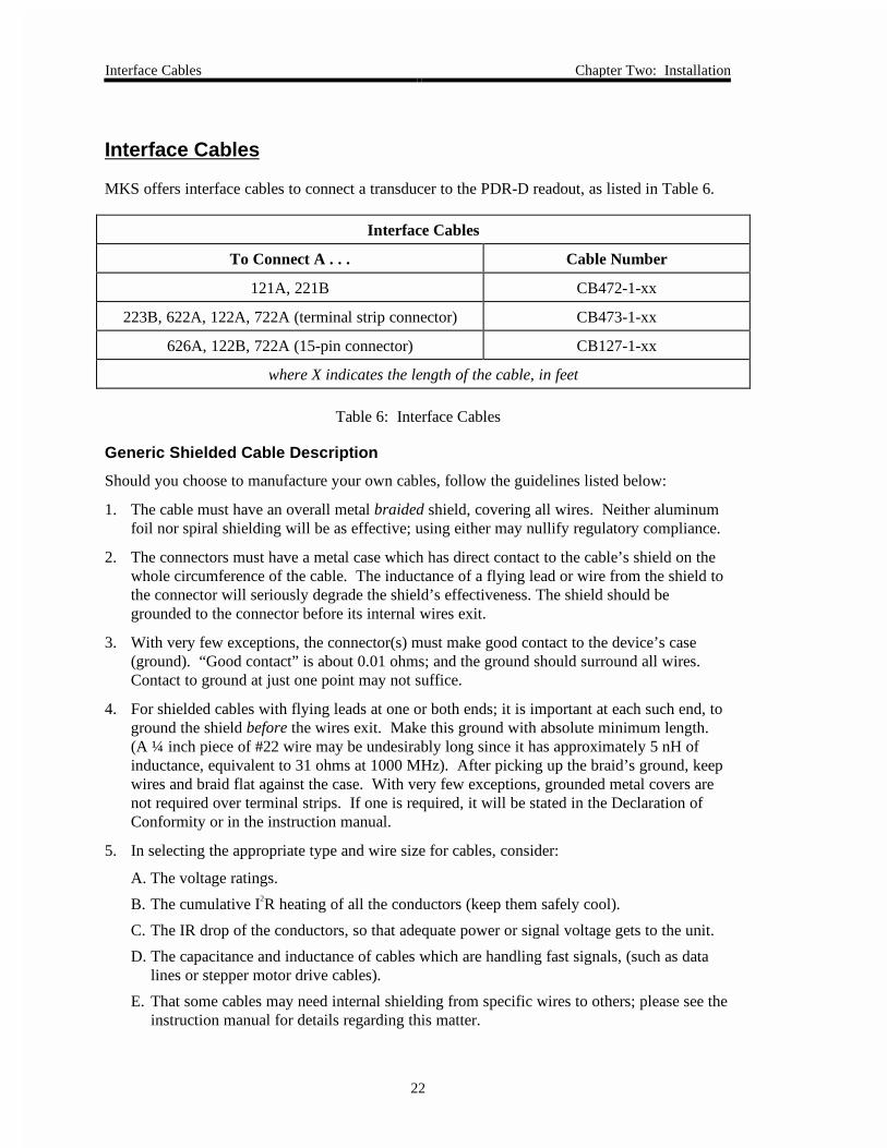
Interface Cables
MKS offers interface cables to connect a transducer to the PDR-D readout, as listed in Table 6.
Interface Cables
To Connect A . . . Cable Number
121A, 221B CB472-1-xx
223B, 622A, 122A, 722A (terminal strip connector) CB473-1-xx
626A, 122B, 722A (15-pin connector) CB127-1-xx
where X indicates the length of the cable, in feet
Table 6: Interface Cables
Generic Shielded Cable Description
Should you choose to manufacture your own cables, follow the guidelines listed below:
1. The cable must have an overall metal braided shield, covering all wires. Neither aluminumfoil nor spiral shielding will be as effective; using either may nullify regulatory compliance.
2. The connectors must have a metal case which has direct contact to the cable’s shield on thewhole circumference of the cable. The inductance of a flying lead or wire from the shield tothe connector will seriously degrade the shield’s effectiveness. The shield should begrounded to the connector before its internal wires exit.
3. With very few exceptions, the connector(s) must make good contact to the device’s case(ground). “Good contact” is about 0.01 ohms; and the ground should surround all wires.Contact to ground at just one point may not suffice.
4. For shielded cables with flying leads at one or both ends; it is important at each such end, toground the shield before the wires exit. Make this ground with absolute minimum length.(A ¼ inch piece of #22 wire may be undesirably long since it has approximately 5 nH ofinductance, equivalent to 31 ohms at 1000 MHz). After picking up the braid’s ground, keepwires and braid flat against the case. With very few exceptions, grounded metal covers arenot required over terminal strips. If one is required, it will be stated in the Declaration ofConformity or in the instruction manual.
5. In selecting the appropriate type and wire size for cables, consider:
A. The voltage ratings.
B. The cumulative I2R heating of all the conductors (keep them safely cool).
C. The IR drop of the conductors, so that adequate power or signal voltage gets to the unit.
D. The capacitance and inductance of cables which are handling fast signals, (such as datalines or stepper motor drive cables).
E. That some cables may need internal shielding from specific wires to others; please see theinstruction manual for details regarding this matter.
Chapter Two: Installation Product Location and Requirements
23
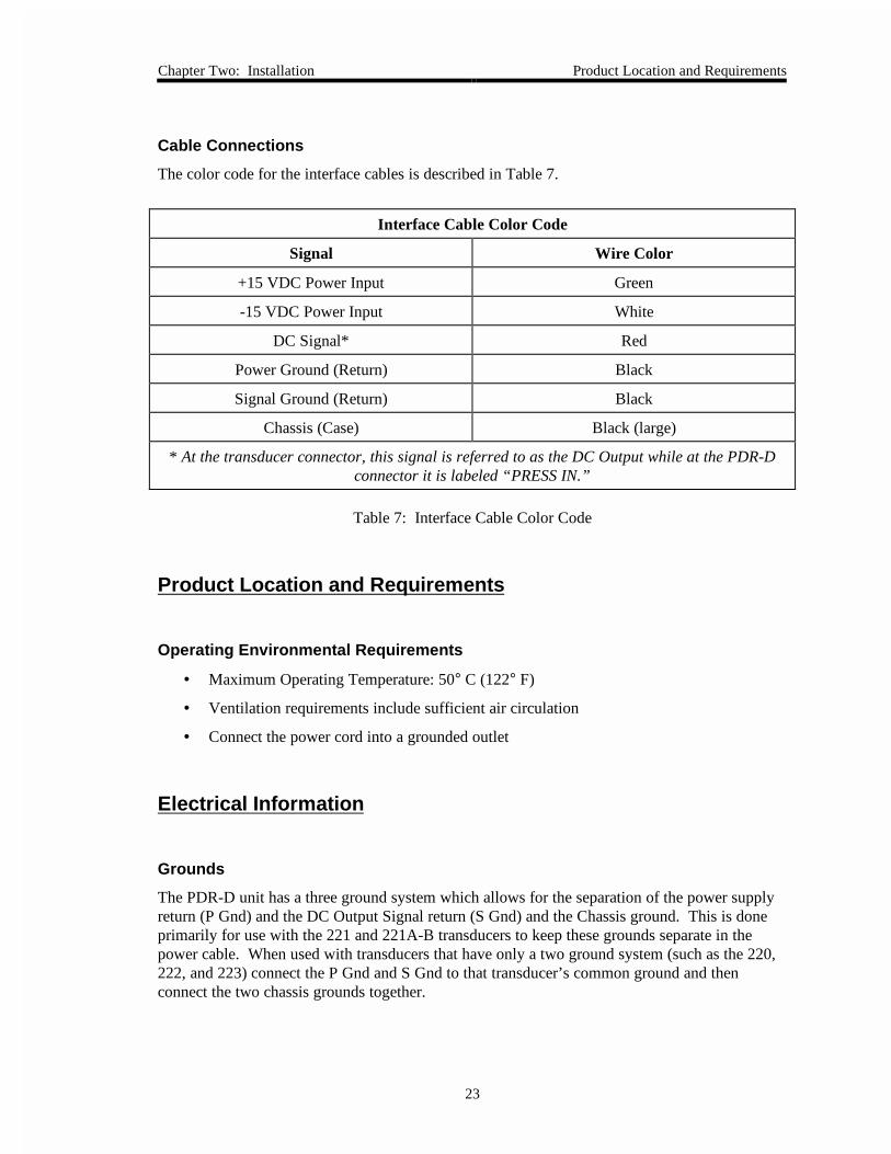
Cable Connections
The color code for the interface cables is described in Table 7.
Interface Cable Color Code
Signal Wire Color
+15 VDC Power Input Green
-15 VDC Power Input White
DC Signal* Red
Power Ground (Return) Black
Signal Ground (Return) Black
Chassis (Case) Black (large)
* At the transducer connector, this signal is referred to as the DC Output while at the PDR-Dconnector it is labeled “PRESS IN.”
Table 7: Interface Cable Color Code
Product Location and Requirements
Operating Environmental Requirements
• Maximum Operating Temperature: 50° C (122° F)
• Ventilation requirements include sufficient air circulation
• Connect the power cord into a grounded outlet
Electrical Information
Grounds
The PDR-D unit has a three ground system which allows for the separation of the power supplyreturn (P Gnd) and the DC Output Signal return (S Gnd) and the Chassis ground. This is doneprimarily for use with the 221 and 221A-B transducers to keep these grounds separate in thepower cable. When used with transducers that have only a two ground system (such as the 220,222, and 223) connect the P Gnd and S Gnd to that transducer’s common ground and thenconnect the two chassis grounds together.
Setup Chapter Two: Installation
24
Setup
Note Mount the PDR-D unit in a location that provides sufficient aircirculation.
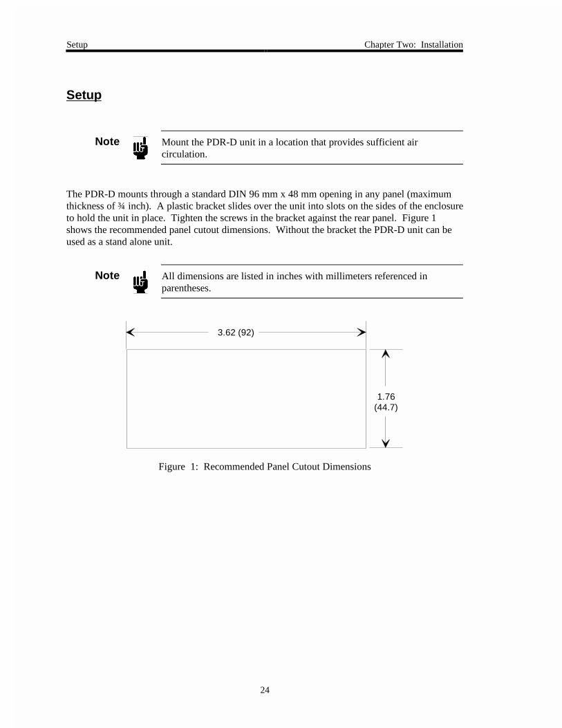
The PDR-D mounts through a standard DIN 96 mm x 48 mm opening in any panel (maximumthickness of ¾ inch). A plastic bracket slides over the unit into slots on the sides of the enclosureto hold the unit in place. Tighten the screws in the bracket against the rear panel. Figure 1shows the recommended panel cutout dimensions. Without the bracket the PDR-D unit can beused as a stand alone unit.
Note All dimensions are listed in inches with millimeters referenced inparentheses.
3.62 (92)
1.76(44.7)
Figure 1: Recommended Panel Cutout Dimensions
Chapter Three: Overview Front Panel Controls
25
Chapter Three: Overview
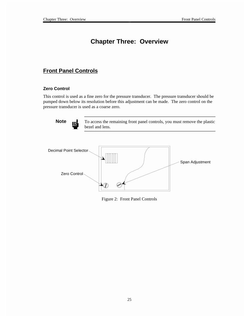
Front Panel Controls
Zero Control
This control is used as a fine zero for the pressure transducer. The pressure transducer should bepumped down below its resolution before this adjustment can be made. The zero control on thepressure transducer is used as a coarse zero.
Note To access the remaining front panel controls, you must remove the plasticbezel and lens.
Decimal Point Selector
Zero Control
Span Adjustment
Figure 2: Front Panel Controls
Front Panel Controls Chapter Three: Overview
26
How To Access Front Panel Controls
Figure 3 shows the how the components of the PDR-D enclosure fit together.
Figure 3: Exploded View of the PDR-D Unit
Span Adjust
This control is used to set the proper full scale display reading for a full scale input, that is, a +10VDC input yields a display of +10000.
Note The span adjustment is made at the factory. Do not adjust the spancontrol.
Chapter Three: Overview Front Panel Controls
27
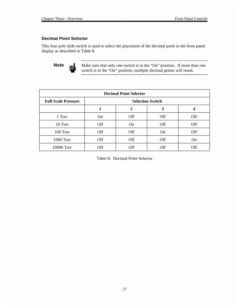
Decimal Point Selector
This four pole slide switch is used to select the placement of the decimal point in the front paneldisplay as described in Table 8.
Note Make sure that only one switch is in the “On” position. If more than oneswitch is in the “On” position, multiple decimal points will result.
Decimal Point Selector
Full Scale Pressure Selection Switch
1 2 3 4
1 Torr On Off Off Off
10 Torr Off On Off Off
100 Torr Off Off On Off
1000 Torr Off Off Off On
10000 Torr Off Off Off Off
Table 8: Decimal Point Selector
Rear Panel Controls Chapter Three: Overview
28
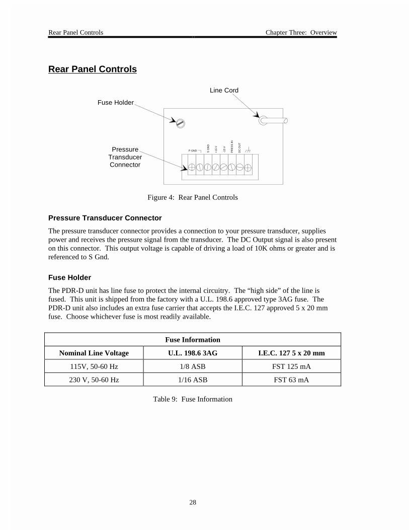
Rear Panel Controls
P GND S G
ND
+15
V
-15
V
PR
ES
S IN
DC
OU
T
PressureTransducer Connector
Fuse Holder
Line Cord
Figure 4: Rear Panel Controls
Pressure Transducer Connector
The pressure transducer connector provides a connection to your pressure transducer, suppliespower and receives the pressure signal from the transducer. The DC Output signal is also presenton this connector. This output voltage is capable of driving a load of 10K ohms or greater and isreferenced to S Gnd.
Fuse Holder
The PDR-D unit has line fuse to protect the internal circuitry. The “high side” of the line isfused. This unit is shipped from the factory with a U.L. 198.6 approved type 3AG fuse. ThePDR-D unit also includes an extra fuse carrier that accepts the I.E.C. 127 approved 5 x 20 mmfuse. Choose whichever fuse is most readily available.
Fuse Information
Nominal Line Voltage U.L. 198.6 3AG I.E.C. 127 5 x 20 mm
115V, 50-60 Hz 1/8 ASB FST 125 mA
230 V, 50-60 Hz 1/16 ASB FST 63 mA
Table 9: Fuse Information
Chapter Three: Overview Rear Panel Controls
29
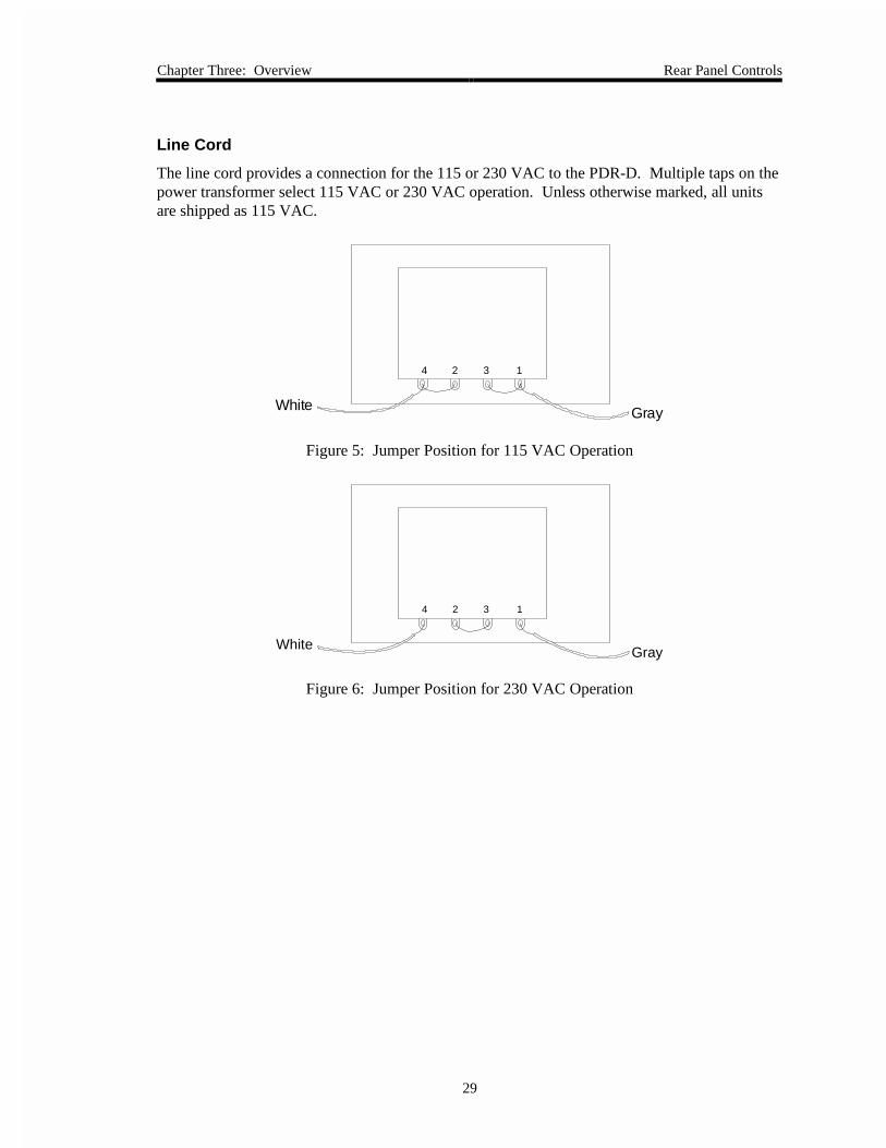
Line Cord
The line cord provides a connection for the 115 or 230 VAC to the PDR-D. Multiple taps on thepower transformer select 115 VAC or 230 VAC operation. Unless otherwise marked, all unitsare shipped as 115 VAC.
White Gray
4 2 3 1
Figure 5: Jumper Position for 115 VAC Operation
White Gray
4 2 3 1
Figure 6: Jumper Position for 230 VAC Operation

Rear Panel Controls Chapter Three: Overview
30
This page intentionally left blank.
Chapter Four: Operation General Information
31
Chapter Four: Operation
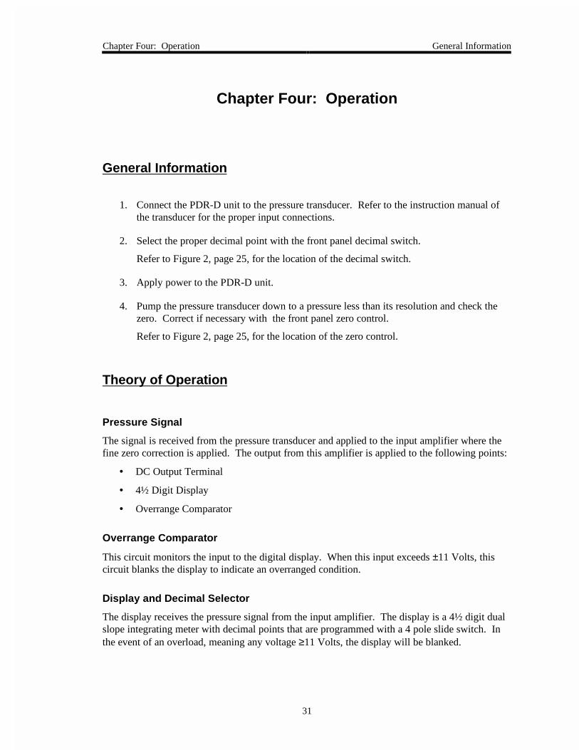
General Information
1. Connect the PDR-D unit to the pressure transducer. Refer to the instruction manual ofthe transducer for the proper input connections.
2. Select the proper decimal point with the front panel decimal switch.
Refer to Figure 2, page 25, for the location of the decimal switch.
3. Apply power to the PDR-D unit.
4. Pump the pressure transducer down to a pressure less than its resolution and check thezero. Correct if necessary with the front panel zero control.
Refer to Figure 2, page 25, for the location of the zero control.
Theory of Operation
Pressure Signal
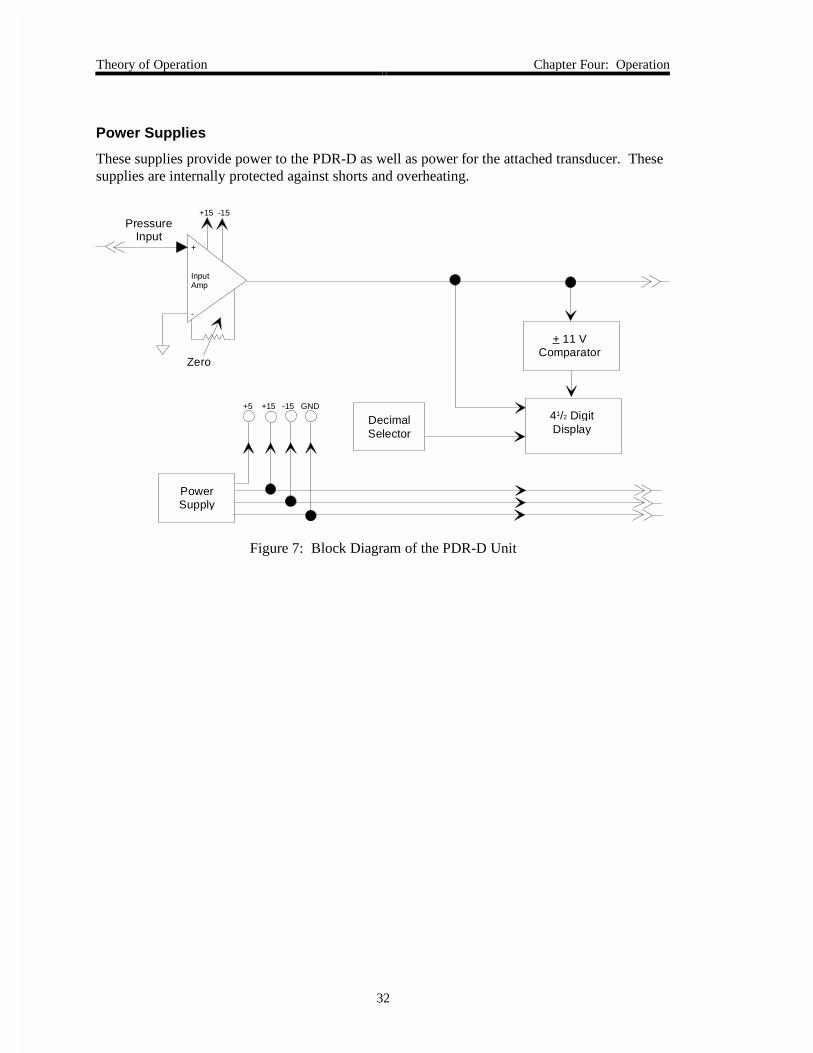
The signal is received from the pressure transducer and applied to the input amplifier where thefine zero correction is applied. The output from this amplifier is applied to the following points:
• DC Output Terminal
• 4½ Digit Display
• Overrange Comparator
Overrange Comparator
This circuit monitors the input to the digital display. When this input exceeds ±11 Volts, thiscircuit blanks the display to indicate an overranged condition.
Display and Decimal Selector
The display receives the pressure signal from the input amplifier. The display is a 4½ digit dualslope integrating meter with decimal points that are programmed with a 4 pole slide switch. Inthe event of an overload, meaning any voltage ≥11 Volts, the display will be blanked.
Theory of Operation Chapter Four: Operation
32
Power Supplies
These supplies provide power to the PDR-D as well as power for the attached transducer. Thesesupplies are internally protected against shorts and overheating.
+
InputAmp
-
+15 -15
Zero
+ 11 VComparator
41/2 DigitDisplay
Decimal Selector
PowerSupply
+5 +15 -15 GND
PressureInput
Figure 7: Block Diagram of the PDR-D Unit

Chapter Five: Maintenance and Troubleshooting General Information
33
Chapter Five: Maintenance and Troubleshooting
General Information
Periodically check for wear on the cables and inspect the enclosure for visible signs of damage.
Should it become necessary to attempt repair of the unit in the field, first isolate the source of theproblem; the pressure transducer or the PDR-D unit. Any repair to the pressure transducer willusually require a recalibration. The PDR-D unit may be repaired without calibration as long asnone of the calibration adjustments have been tampered with or changed.
How To Clean the Unit
Periodically wipe down the unit with a damp cloth.
Fault Isolation
The first approach to deal with a problem in a system is to isolate the section of the system wherethe fault lies. Once this is done, the problem can be corrected. The PDR-D unit and theassociated pressure transducer can be broken down into the following sections:
• Power Supply
• Pressure Signal Amplification and Readout
Since a problem in the power supply will effect the performance of all sections, it is important tobegin the fault isolation at this point.
1. Measure the ±15 Volt supplies on the pressure transducer connector. (Reference to PGnd.) The voltages should be within the range of 14.7 to 15.3 Volts and the AC rippleshould be less than 10 mV peak-to-peak.
2. Measure the +5 Volt supply referenced to D Gnd. The voltage should measure +4.75 to5.25 Volts and the AC ripple should be below 20 mV peak-to-peak. If the voltages insteps 1 and 2 are within the correct range, proceed to step 5. If the voltages are incorrect,continue with step 3.
3. Disconnect the pressure transducer and repeat the voltage measurements. If the voltagesare now correct, the pressure transducer is at fault. If the voltages are still incorrect, theproblem is in the circuits of the PDR-D unit or the power supply itself.
Fault Isolation Chapter Five: Maintenance and Troubleshooting
34
4. Isolate the power supply from the circuits in the PDR-D unit by disconnecting the powersupply jumpers. This will indicate a defective supply or some form of short ormalfunction in the PDR-D circuits.
If the power supply is defective, return the unit to MKS for further diagnostic testing. Ifthe power supply is functioning properly, continue with step 5.
5. Examine the pressure signal path through the system.
6. Use an external meter to measure the output of the pressure transducer (PRESS IN) at therear terminal block of the PDR-D unit. If this voltage closely (±0.2 V) tracks1 thevoltage that is displayed on the front panel meter, but is still in error, the PDR-D unit isfunctioning properly and the problem is in the pressure transducer or cable. If thevoltage does not track, proceed to step 7.
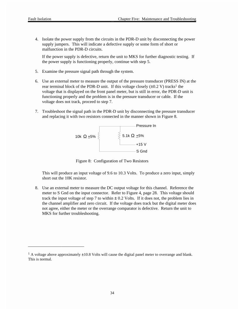
7. Troubleshoot the signal path in the PDR-D unit by disconnecting the pressure transducerand replacing it with two resistors connected in the manner shown in Figure 8.
Pressure In
5.1k +5%Ω
+15 V
S Gnd
10k +5%Ω
Figure 8: Configuration of Two Resistors
This will produce an input voltage of 9.6 to 10.3 Volts. To produce a zero input, simplyshort out the 10K resistor.
8. Use an external meter to measure the DC output voltage for this channel. Reference themeter to S Gnd on the input connector. Refer to Figure 4, page 28. This voltage shouldtrack the input voltage of step 7 to within ± 0.2 Volts. If it does not, the problem lies inthe channel amplifier and zero circuit. If the voltage does track but the digital meter doesnot agree, either the meter or the overrange comparator is defective. Return the unit toMKS for further troubleshooting.
1 A voltage above approximately ±10.8 Volts will cause the digital panel meter to overrange and blank.This is normal.
Appendix A: Product Specifications Electrical Specifications
35
Appendix A: Product Specifications
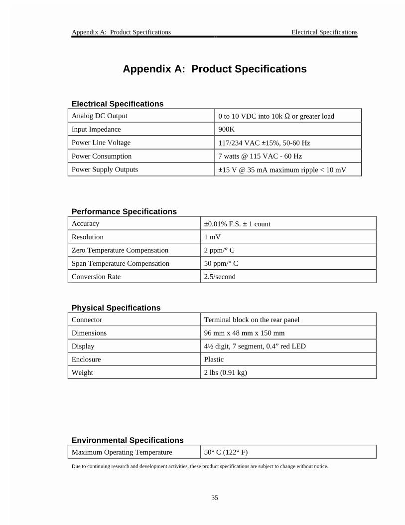
Electrical SpecificationsAnalog DC Output 0 to 10 VDC into 10k Ω or greater load
Input Impedance 900K
Power Line Voltage 117/234 VAC ±15%, 50-60 Hz
Power Consumption 7 watts @ 115 VAC - 60 Hz
Power Supply Outputs ±15 V @ 35 mA maximum ripple < 10 mV
Performance SpecificationsAccuracy ±0.01% F.S. ± 1 count
Resolution 1 mV
Zero Temperature Compensation 2 ppm/° C
Span Temperature Compensation 50 ppm/° C
Conversion Rate 2.5/second
Physical SpecificationsConnector Terminal block on the rear panel
Dimensions 96 mm x 48 mm x 150 mm
Display 4½ digit, 7 segment, 0.4” red LED
Enclosure Plastic
Weight 2 lbs (0.91 kg)
Environmental SpecificationsMaximum Operating Temperature 50° C (122° F)
Due to continuing research and development activities, these product specifications are subject to change without notice.

Environmental Specifications Appendix A: Product Specifications
36
Appendix B: Model Code Explanation Model Code
37
Appendix B: Model Code Explanation
Model Code
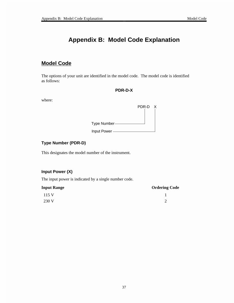
The options of your unit are identified in the model code. The model code is identifiedas follows:
PDR-D-X
where:
Type Number
Input Power
XPDR-D
Type Number (PDR-D)
This designates the model number of the instrument.
Input Power (X)
The input power is indicated by a single number code.
Input Range Ordering Code
115 V 1
230 V 2

Model Code Appendix B: Model Code Explanation
38
This page intentionally left blank.
Index
39
Index
B
Baratron, 17
C
Cable, color code, 23
Cables, 22
Customer support, 19
D
Decimal point selector, 26, 31
Dimensions, 24
DIN, 17, 24
Display, 31, 35
E
Electrical, 23, 33, 35
F
Fault isolation, 33
Front panel, 25
Fuse holder, 28
Fuse information, 28
G
Grounds, 23
I
Input power, 29, 37
Interface cables, 22
L
Line cord, 29
M
Maintenance, 33
Manual organization, 18
Model code, 37
Mounting, 24
O
Operation, 31
Overrange comparator, 31, 34
P
PDR-D-1, 17, 29
PDR-D-2, 17, 29
Power supply, 32, 34
Pressure signal, 31
Pressure transducer connector, 28
R
Rear panel, 28
Returning the product, 19, 21
S
Safety information, 1–16
Span adjust, 26
Specifications
electrical, 35
environmental, 35

Index
40
performance, 35
physical, 35
T
Temperature, 23
Troubleshooting, 33
V
Ventilation, 23
Z
Zero control, 25, 31