Embed Size (px)
Citation preview

Performance Analysis of Distance Protection Using Different Impedance Calculation Methods
Mohit Sharma, Megger Vijay Shanmugasundaram, PowerGrid Engineering LLC
Introduction
Various combinations of voltages and currents are possible in the power system in an event of fault. Distance relays use these voltage and current phasors, obtained from PTs and CTs, to calculate impedance. The relay operates when the calculated impedance is below the reach or set impedance. The operation can be better understood when plotted on an impedance plane. Mho circles and quadrilateral characteristic are essentially the most popular characteristics used all across the world since they are inherently directional and provide well defined reach with minimal over reaching and under reaching errors. All the impedance points that lie within the characteristic are considered operating points.
Validation of the reach settings, operating times and the characteristic itself is crucial to ensure proper functionality of the distance element. This involves simulating different fault scenarios by injecting different voltage and current values from a test equipment. There are different calculation methods that can be used to perform the testing. This paper provides a detailed explanation of those methods and their performance analysis with different settings and characteristics implemented in one of the digital relays.
Testing of Distance Elements
Over the years, different methods have been adopted to test the characteristics, reach and maximum torque angle of a distance relay as part of acceptance testing. The methodology of testing has been slowly progressing from steady state to simulating real system conditions but the selection of the most appropriate method is a subjective matter and it depends on various factors such as time constraints, application and test set limitations. The paper will discuss three of the most common implemented methods- constant voltage, constant current and constant source impedance, and will cover the benefits and drawbacks of one method over the other.
a) Constant Voltage Method
It is a steady state testing method that is accomplished by keeping fault voltages constant but increasing the magnitude of current. The distance element operates when the ratio of applied test voltage to current reaches the impedance pick-up point. This method has been proven successful on many occasions provided there is availability of the right test equipment. The number of voltage and current channels on a test equipment is also a deciding factor if

thorough testing for all the fault types- three phase, phase to phase and phase to ground faults is desired.
In the past, this method had been achieved by the usage of variable autotransformers and phase shifters to produce appropriate voltages and currents. As the technology in electronics progressed, modern test equipment evolved were able to generate both voltage and current with accurate phase angle differences. Albeit advances in the output levels of test equipment, it is still not possible to manufacture something that can output infinite voltage, infinite current and be suitable for every single test scenario.
Short transmission lines have reach settings with low magnitudes. It can possibly lead to requirement of high currents if a low value of voltage is held constant. As an example, let us consider simulating a phase to phase (AB) fault for line with line impedance of 0.057 Ω at 83.76
degrees. The nominal secondary voltage is assumed as 67 V. If Zone-1 reach is set at 85% of the line impedance, the value turns out to be 0.05 ohms in this example. The secondary faulted values for Zone-1 at a constant voltage of 33.5 V would be as below:
Phase Magnitude Angle Frequency Magnitude Angle Frequency A 335 A 53.76 60 33.5 V 30 60 B 335 A 233.76 60 33.5 V 90 60 C 0 240 60 69 V 240 60
It is evident that the amount of current required to be injected is 335 A on one phase. None of modern test equipment can deliver such a high magnitude. So, it is usually the output current limitations of the test set that determines the test method.
The reduction of voltage to meet the needs of output current limitations is a way around to test the elements in this case. The downside is that the voltage required to test a very low reach setting might not be sufficient enough to act as a polarizing quantity. A self-polarized relay will not operate at all due to unavailability of voltage polarization. However, there can be several real time conditions that can lead to complete voltage collapse such as close-in bolted faults. Relays cannot afford to not operate during such conditions.
For this reason, many distance relays, of both electro-mechanical and micro-processor design, use memory action to produce a short duration output for zero voltage faults at the relay location. The polarizing circuit contains a tuned circuit and, in effect, “remembers” the previous faulted voltage long enough for the relay to make a decision as to whether the fault is in forward or reverse direction.
The memory action creates a dynamic characteristic which either expands or shrinks compared to the steady state characteristic. Consider a close-in fault in the forward direction. The impedance point will be close to zero but in the positive direction as shown in Figure [1]. The location of the relay is at origin O. To make sure the characteristic realizes this as an internal

fault, the relay expands the characteristic as shown by the dotted circle in the figure. Shrinking happens when the impedance point is close to zero but in the reverse direction to clearly distinguish as an external fault.
Fig 1: Effect of Mho Expansion
When testing a memory polarized distance unit, the way the pre-fault and faulted voltages are managed affects the test results. The memory effect will not be noticeable when constant voltage method is applied. Advanced methods such as constant source impedance has to be employed to test the true behavior of a relay.
b) Constant Current Method
It is a steady state method where the fault currents are kept constant while the voltages are ramped down until the desired impedance is seen by the relay. Similar to the constant voltage method, the impedance point is brought from a region outside the characteristic to the inside till the relay operates. The characteristic can be validated by choosing a few testing points at different phase angles with reference to the line angle (MTA).
As discussed before, constant current method has benefits of keeping the current constant within the rated output of a test set. Testing reach points on short lines can be successfully accomplished by this method.
Identical to constant voltage method, this method does not test the dynamic expansion and contraction of the characteristic.

c) Constant Source Impedance Method
By changing either voltage or current, the characteristic will change. This change is caused in part by the equivalent source impedance that is behind the protective relay. By not varying both voltages and currents at the same time, the source impedance will change with each test point on the characteristic curve. The memory effect can truly be tested by changing both voltages and currents and keeping the source impedance constant.
The diameter of the initial dynamic characteristic will be equal to the sum of source impedance and the relay reach. On that account, expansion of mho characteristic depends on the magnitude of source impedance, a concept commonly known as “expanding back to source”. Higher the ratio of source impedance to line impedance (SIR) of a system, higher will be the expansion.
The theory of symmetrical components is important in order to design a constant source impedance model. If the source impedance is not known, then an educated guess can be made to simulate different cases. It is easiest to determine the source impedance in terms of its ratio to line impedance since it is most likely to be known. Let us now dive in to the calculations behind constant source impedance model.
Fig 2: Dynamic mho with source impedance and positive reach
With the help of geometry, the dynamic reach of the mho circle can be determined. Fig [2] shows an expanded mho characteristic with the relay position centered at origin. The assumption is that the circle is designed for a forward zone. The line segment that extends back from the origin in third quadrant till the edge of the circle is the source impedance Zs. For ease in understanding, the source impedance angle was chosen to be equivalent to the positive sequence line impedance angle so that the system would remain homogenous.
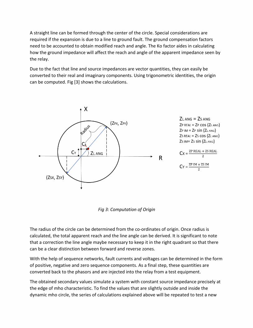
A straight line can be formed through the center of the circle. Special considerations are required if the expansion is due to a line to ground fault. The ground compensation factors need to be accounted to obtain modified reach and angle. The Ko factor aides in calculating how the ground impedance will affect the reach and angle of the apparent impedance seen by the relay.
Due to the fact that line and source impedances are vector quantities, they can easily be converted to their real and imaginary components. Using trigonometric identities, the origin can be computed. Fig [3] shows the calculations.
Fig 3: Computation of Origin
The radius of the circle can be determined from the co-ordinates of origin. Once radius is calculated, the total apparent reach and the line angle can be derived. It is significant to note that a correction the line angle maybe necessary to keep it in the right quadrant so that there can be a clear distinction between forward and reverse zones.
With the help of sequence networks, fault currents and voltages can be determined in the form of positive, negative and zero sequence components. As a final step, these quantities are converted back to the phasors and are injected into the relay from a test equipment.
The obtained secondary values simulate a system with constant source impedance precisely at the edge of mho characteristic. To find the values that are slightly outside and inside the dynamic mho circle, the series of calculations explained above will be repeated to test a new

impedance point. Modern testing solutions perform the whole calculations through software programs to reduce the testing time.
Performance Analysis of Different Methods
The main purpose of performance analysis of all the three testing methods is to provide user an idea about the differences. The performance parameters in this paper will be strictly limited to characteristic test for faults at different fault angles. Two different characteristics for one of the most popular transmission digital relays will be carefully studied for the above parameter. The relay in consideration has a +/- 3% tolerance on reach settings.
For this paper, the power system being discussed is modeled in Fig [4] below.
Fig. 4: Single source power system model with mho based protection
Unlike most other papers on this topic, the system being modeled uses a single source instead of a two source model. Using a single source model simplifies the calculations required to determine the faulted voltages and currents. The positive sequence line impedance of the line protected ZL is 3.77 ohms at 83.46o maximum torque angle. CT and PT ratios are 600 and 3000 respectively. The nominal line voltage at PT secondary is 115 V.
A) Mho Characteristic Enabled:
Case 1 – Constant Voltage Method for Mho Circle
This case reflects the operation of zone-1 pick-up for a characteristic test using constant voltage method. A steady state voltage of half the nominal voltage is selected. For the power system model described above, the phase to neutral value of voltage will be 33.5 V. It is an arbitrarily chosen value so that the current is under the output rating of the test equipment. The comparative analysis for all the constant voltage method cases will be performed with the same
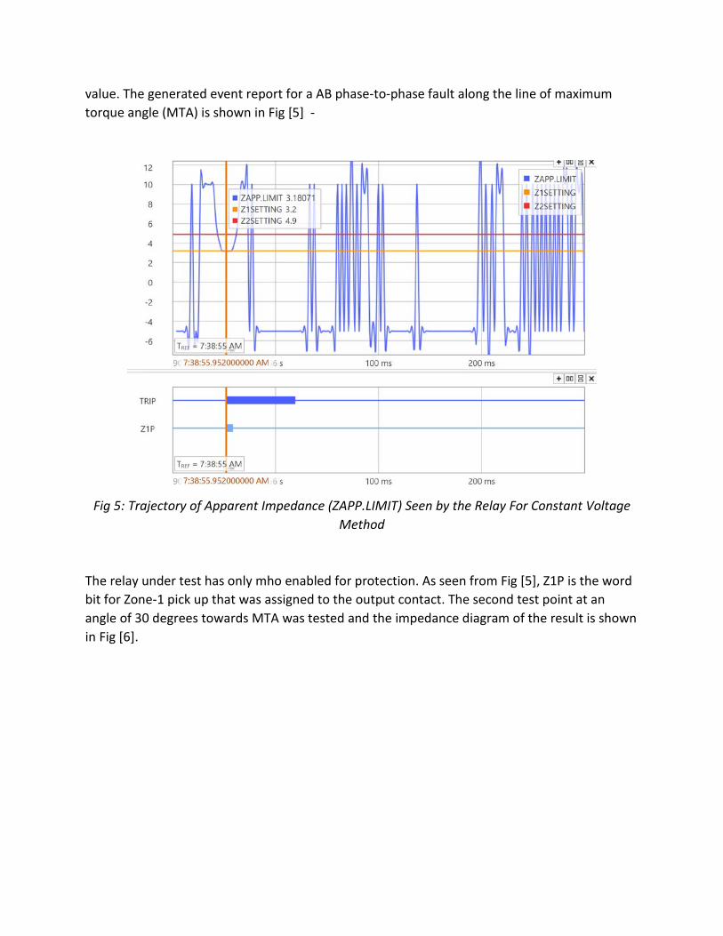
value. The generated event report for a AB phase-to-phase fault along the line of maximum torque angle (MTA) is shown in Fig [5] -
Fig 5: Trajectory of Apparent Impedance (ZAPP.LIMIT) Seen by the Relay For Constant Voltage Method
The relay under test has only mho enabled for protection. As seen from Fig [5], Z1P is the word bit for Zone-1 pick up that was assigned to the output contact. The second test point at an angle of 30 degrees towards MTA was tested and the impedance diagram of the result is shown in Fig [6].

Fig 6: Impedance Diagram for Constant Voltage Method at 30o Test Angle
The results of the test conducted are shown in Table 1.
Test Angle Measured Faulted Voltage at Pick-Up (VAN)
Measured Faulted Current at Pick-Up (IAN)
Theoretical Impedance (Ω)
Calculated Impedance (Ω)
% Error
83.46O 33.5 V 5.269 A 3.2 3.18 0.625 30O 33.5 V 8.778 A 1.93 1.908 1.14
Table 1: Results of Constant Voltage Method on Mho Characteristic
Case 2 – Constant Current Method for Mho Circle
This case reflects the operation of Zone-1 pick-up for a characteristic test using constant current method. For the power system model described above, the assumed phase to neutral value of faulted current is held at 9.959 A. The comparative analysis for all the constant current method cases will be performed with the same value. The generated event report for a AB phase-to-phase fault along the line of maximum torque angle (MTA) is shown in Fig [7].

Fig 7: Trajectory of Apparent Impedance (ZAPP.LIMIT) Seen by the Relay For Constant Current Method
The trip equation has the word bit for mho phase-to-phase AB element (MAB1) as shown in Fig [6]. The vertical orange colored cursor shows the exact point at which the output contact of the relay was closed. It can be seen that the calculated impedance by the relay at the time of operation was 3.172 Ω. The second test point at an angle of 30 degrees towards MTA was tested and the impedance diagram of the result is shown in Fig [8].

Fig 8: Impedance Diagram for Constant Current Method at 30o Test Angle
The results obtained from this method are noted in Table 2. Theoretical impedance shown in Table 2 is the expected pick-up value whereas calculated impedance is the measured value at which the relay operated.
Test Angle Measured Faulted Voltage at Pick-Up (VAN)
Measured Faulted Current at Pick-Up
(IAN)
Theoretical Impedance
(Ω)
Calculated Impedance
(Ω)
% Error
83.46O 63.18 V 9.959 A 3.2 3.172 0.87
30O 37.84 V 9.959 A 1.93 1.9 1.14
Table 2: Results of Constant Current Method on Mho Characteristic

Case 3- Constant Source Impedance Method for Mho Circle
This case reflects the operation of Zone-1 pick-up for a characteristic test using constant source impedance method. Healthy pre-fault values are applied before the faulted quantities to provide source impedance to the relay. For testing, a value equal to 20% of the positive sequence line impedance is assumed. The resulted source impedance turns out to be 0.2 x 3.77 = 0.754 Ω. Another guess is made for the source impedance angle. It is kept to be same as the maximum torque angle for simplicity in calculations of faulted voltages and currents. Pulse ramping technique is employed for this test because of the possibility of high values of faulted phasors. The generated event report for a AB phase-to- phase fault along the line of maximum torque angle (MTA) is shown in Fig [9].
Fig 9: Trajectory of Apparent Impedance (ZAPP.LIMIT) Seen by the Relay For Constant Source Impedance Method
It can be seen that the calculated impedance by the relay at the time of operation was 3.182 Ω, better in terms of accuracy compared to the above discussed methods. The second test point at an angle of 30 degrees towards MTA was tested and the impedance diagram of the result is shown in Fig [10].

Fig 10: Dynamic Impedance Diagram for Constant Source Impedance Method at 30o Test Angle
The results obtained from this test are presented in Table 3. The faulted voltages and currents are yielded from symmetrical component theory. Only A phase phasor quantities are shown in the table.
Test Angle Measured Faulted Voltage at Pick-Up (VAN)
Measured Faulted Current at Pick-Up
(IAN)
Theoretical Impedance
(Ω)
Calculated Impedance
(Ω)
% Error
83.46O 60.76 V 20.723 A 3.2 3.182 0.56
30O 59.83 V 19.825 A 1.93 2.208 12.62
Table 3: Results of Constant Source Impedance Method on Mho Characteristic

Interpretation of Results
Table 1 and 2 do not have notable differences both at MTA and at an angle far off from MTA. However, Table 3 has around 13% error in pick-up at 30o phase angle. It is simply because constant source impedance model is tracking the dynamic expansion of the characteristic whereas theoretical impedances are the values at steady state. Fig [9] shows that the chosen source impedance is accurate enough to trip the relay on the edge of dynamic mho.
Another striking point to observe is that there is negligible expansion at MTA but noticeable at angles far from MTA. All the models have almost same results along the line of maximum torque angle (MTA).
B) Quadrilateral Characteristic Enabled
The power system model is considered similar to that designed for mho characteristic but the settings for pick-up are different in such a fashion that they provide a high resistive coverage.
Zone-1 reactive reach (XP1) = 3.2 ohms
Zone-1 resistive reach (RP1) = 12.48 ohms
Fig. 10a: Single source power system model with Quad based protection
The positive sequence line impedance of the line protected ZL is kept same at 3.77 ohms at 83.46o maximum torque angle. CT and PT ratios are 600 and 3000 respectively. The nominal line voltage at PT secondary is 115 V.
Case 4: Constant Voltage Method for Quad
Similar to the application on mho element, constant voltage in this case is held at 33.5 V. The test points for a AB phase-to-phase fault along the line of maximum torque angle (MTA) of 83.46o and for a test angle of 15o is shown in Fig [11].
G
21
3.77 Ω at 83.46 degrees MTA

Fig 11: Test Points for a Constant Voltage Method
The red cross in Fig [11] signify that the actual impedance recorded by the relay is outside the tolerance on the expected impedance. Green dots imply a pass in test. The following results were obtained after this test-
Test Angle Measured Faulted Voltage at Pick-Up (VAN)
Measured Faulted Current at Pick-Up
(IAN)
Theoretical Impedance
(Ω)
Calculated Impedance
(Ω)
% Error
83.46O 33.5 V 5.25 A 3.2 3.19 0.31
15O 33.5 V 1.404 A 12.36 11.93 3.48
Table 4: Results of Constant Voltage Method on Quad Characteristic
Case 5: Constant Current Method for Quad
Similar to the application on mho element, constant current in this case is held at 9.959 A. The test points for a AB phase-to-phase fault along the line of maximum torque angle (MTA) of 83.46o and for a test angle of 15o is shown in Fig [12]-

Fig 12: Test Points for a Constant Current Method
The following results were obtained after this test-
Test Angle Measured Faulted Voltage at Pick-Up (VAN)
Measured Faulted Current at Pick-Up
(IAN)
Theoretical Impedance
(Ω)
Calculated Impedance
(Ω)
% Error
83.46O 63.54 V 9.959 A 3.2 3.19 0.31
15O 98.09 V 4.9 A 12.36 10.01 19.01
Table 5: Results of Constant Current Method on Quad Characteristic
Case 6: Constant Source Impedance Method for Quad
Similar to the application on mho element, constant source impedance in this case is held at 0.754 Ω at 83.46o source angle. The test points for a AB phase-to-phase fault along the line of maximum torque angle (MTA) of 83.46o and for a test angle of 15o is shown in Fig [13].

Fig 13: Test Points for a Constant Source Impedance Method
The following results were obtained after this test-
Test Angle Measured Faulted Voltage at Pick-Up (VAN)
Measured Faulted Current at Pick-Up
(IAN)
Theoretical Impedance
(Ω)
Calculated Impedance
(Ω)
% Error
83.46O 11.94 V 17.39 A 3.2 3.19 0.31
15O 46.3 V 4.58 A 12.36 12.03 2.67
Table 6: Results of Constant Source Impedance Method on Quad Characteristic
Interpretation of Results
Quad elements usually do not follow the principle of memory voltage polarization. The question that arises in mind is what could be some other reasons of change in apparent impedances for 15o angle at the time of trip for all the three testing methods as seen in Table 4, 5 and 6. One logical explanation here could be the effect of directional elements as supervisory units for distance elements. The relay under test uses negative sequence quantities to adjust forward and reverse thresholds on a quad characteristic. Since constant voltage and current methods changes the sequence components, it might affect the actual characteristics of the relay.

Another observation is from Table 5. It shows us that the value of voltage computed for 9.959 A at 15o exceeded the rating of the instrument. A drop in current had to be done so that the voltages were within the specifications of the test instrument.
Conclusion
The effect of dynamic behavior of mho circle can accurately be validated by constant source impedance model. If the right match to the system’s source impedance can be found, precise testing of expansion and contraction can be achieved. On the contrary, constant voltage and current models for the above cases track the steady state characteristic and provides the true nature of relay’s response only when the memory polarization is disabled.
The point of intersection between dynamic and steady state mho circles is along the line of maximum torque angle (MTA). For that reason, the impact of memory polarization on the characteristic can be better realized at fault angles far off from MTA.
Other observations from this paper is if symmetrical components are used to calculate faulted voltages and currents, the directional units supervising the distance elements will be transparent to the testing procedure.