Embed Size (px)
Citation preview
UNCONTROLLED COPY
Planning and designing for pedestrians: guidelines
Department of Transport
Department of Planning
Public Transport Authority
Planning and Designing for Pedestrians: Guidelines
1(Version 6- 01/12/16)
Introduction
Contents
Foreword 3
Acknowledgements 4
1. Quick Reference Index 5
2. Setting the Scene 18
2.1 Government Roles 19
2.2 Strategic Context 21
3. Standards and Guidelines 27
3.1 Standards and Guidelines Summary 28
3.2 MRWA Standards and Guidelines 31
3.3 Other State Government Standards and Guidelines 34
3.4 Local Government Standards and Guidelines 36
3.5 Austroads Guide to Traffic Management and Guide to Road Design Series 38
3.6 Australian Standards Series 44
3.7 International Good Practice Examples 50
4. Legislation and Regulations 52
4.1 Disability Discrimination Act 1992 53
4.2 Road Traffic Code 2000 54
4.3 Main Roads Act 1930 62
5. Land Use Planning 63
5.1 Land Use Planning 64
6. Pedestrian Characteristics 68
6.1 Pedestrian Characteristics 69
7. Pedestrian Paths 76
7.1 Path Widths 77
7.2 Street Furniture 87
7.3 Grates / Covers 91
7.4 Vertical Clearances 93
7.5 Surfaces 95
7.6 Gradients and Ramps 98
(Version 6 - 01/12/2016)
Planning and Designing for Pedestrians: Guidelines
2
Introduction
7.7 Steps and Stairs 103
7.8 Crossovers / Driveways 105
7.9 Barricades (including chicanes and bollards) 106
8. Pedestrian Crossing Elements 108
8.1 Kerb Crossing Ramps and Pedestrian Cut-Throughs 109
8.2 Grab Rails 116
8.3 Tactile Ground Surface Indicators (TGSI) 118
8.4 Audio-Tactile Facilities 125
9. Pedestrian Crossing Facilities 129
9.1 Sight Lines 130
9.2 Pedestrian Crossing Warrants 135
9.3 Mid-Block Crossings 140
9.4 Non-Signalised Intersection Crossings 159
9.5 Signalised Intersection Crossings 163
9.6 Roundabouts 172
9.7 Grade Separated Crossings 177
9.8 Railway Crossings 180
10. Pedestrian Guidance Measures 183
10.1 Lighting 184
10.2 Directional, Service and Tourist Signs 188
10.3 Pedestrian Warning Signs 192
11. Speed and Environmental Changes 194
11.1 School Speed Zones 195
11.2 Variable Speed Zones 200
11.3 Shared Zones 202
11.4 Traffic Calming 206
12. Accessible Car Parking Bays 211
12.1 Accessible Car Parking Bays 212
13. Abbreviations 216
14. References 217
Planning and Designing for Pedestrians: Guidelines
3(Version 6- 01/12/16)
Introduction
Foreword It is my pleasure to introduce to you the comprehensive ‘Planning and Designing for Pedestrians: Guidelines’ which outlines good practice for the design and construction of pedestrian facilities in WA.
Pedestrians form the largest single road-user group. In these Guidelines, the word ‘pedestrian’ includes all non-vehicular mobility (including the use of, for example, wheelchairs, guide dogs or other mobility aids).
Nearly all short trips could be undertaken on foot and even longer trips, whether the main mode of transport is by private car, public transport or cycling - require the road user to be a pedestrian at some stage of the journey. Walking is a key element in the way West Australians travel to work, school and local facilities.
Pedestrians are among the most vulnerable group of road users. In 2010, pedestrians formed 13 per cent of fatalities in the Perth metropolitan region. Not only do they have the least physical protection, pedestrian fatalities comprised disproportionately of the very young and the elderly. While some of these fatalities may be due to a number of factors, pedestrians are unprotected if involved in a crash. It is, therefore, essential to provide facilities that are well designed and appropriate to the particular situation and user group to enhance pedestrian safety throughout the road network system.
Planning and designing good pedestrian infrastructure with well-connected and amenable facilities will benefit the whole community. Creating communities that encourage people to choose walking as a mode of transport is a way to foster more sustainable, healthier and safer communities. Independent travel will be possible for more people including the elderly, children, families and people with disability. Currently one in five people in Australia have a disability. Two out of three people over 75 have a disability and the prevalence of disability will increase further with the ageing of the Australian population. It is estimated that the total number of people who identify themselves as having a disability will increase by about 38 per cent to around 632,600 by 2023.1
Eventually we hope it will be an enjoyable experience to walk, push your pram or wheel your wheelchair all the way along a route safe in the knowledge that problems with crossing roads, negotiating high kerbs and narrow pavements and finding somewhere easily to have a rest are things of the past.
It is great that these Guidelines are a single source document outlining the policies, planning, guidelines and standards for good pedestrian infrastructure and facilities. It is also pleasing to see that there is great interest across government to ensure that people can travel in a safe environment.
This document is a good example of intersectoral collaboration and has been coordinated by the Department of Transport with funding from Departments of Transport, Planning, Disability Services Commission and the Royal Automobile Club of Western Australia and support from WA Local Government Authority, Public Transport Authority, Main Roads WA and the Institute of Public Works Engineering Australia.
Reece Waldock
Director General of Transport
1 Disability Services Commission, WA, Count Me In, page 27

(Version 6 - 01/12/2016)
Planning and Designing for Pedestrians: Guidelines
4
Introduction
Acknowledgements The ‘Planning and Designing for Pedestrians: Guidelines’ is a unique collaboration of the Departments of Transport, Planning, Disability Services Commission, Main Roads WA, WA Local Government Association, Public Transport Authority, The Royal Automobile Club of WA and the Institute of Public Works Engineering Australia WA. The Department of Transport commissioned AECOM and Lachlan Millar and Associates to review and revise the 2004 ‘Infrastructure for Pedestrians’ Manual.Special thanks to the following organisations for funding the project:• DepartmentofTransport• DepartmentofPlanning• DisabilityServicesCommission• TheRoyalAutomobileClubofWA• MainRoadsWAProject Steering Committee members:• AliceHaning(Chair)–DepartmentofTransport• JillianWoolmer–DepartmentofTransport• ShanthiGolestani–DepartmentofPlanning• GaryMcCarney–DepartmentofPlanning• CarolineCarabott–MainRoadsWA• JeffEdwards–DisabilityServicesCommission• JimAltham-PublicTransportAuthority• NinaHewson–WALocalGovernmentAssociation• MarianneCarey-TheRoyalAutomobileClubofWA• FrankStrever–InstituteofPublicWorksEngineeringAustralia(IPWEA)Special acknowledgement to IPWEA and professionals in both state, local and non government organisations that have reviewed and provided feedback on the document.
Photos, graphics and images A special thanks to all organisations for contributing the photos, graphics and images for the use of this Guideline.The images in this document are reproduced with permission from SAI Global under licence number 1111-c055.
Disclaimer: This Guideline is an uncontrolled copy and is to be used at the discretion of each individual. The content of this Guideline is correct at the time of release. It is up to each individual to refer back to the relevant resource centres for the current practices.Any representation, statement, opinion or advice expressed or implied in this publication is made in good faith and on the basis that the government, its employees and agents are not liable for any damage or loss whatsoever which may occur as a result of action taken or not taken (as the case may be) in respect of any representation, statement, opinion or advice referred to herein. Professional advice should be obtained before applying the information contained in this document to particular circumstances.
Published by the Department of Transport140WilliamStreet,PERTHWA6000 T: 08 655 16000 www.transport.wa.gov.au [email protected]
First published November 2011 © Western Australia
Planning and Designing for Pedestrians: Guidelines
5(Version 6 - 01/12/16)
1. Quick Reference Index
1. Quick Reference Index
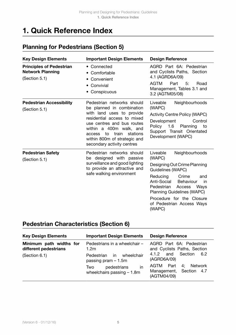
Planning for Pedestrians (Section 5)
Key Design Elements Important Design Elements Design Reference
Principles of Pedestrian Network Planning
(Section 5.1)
• Connected• Comfortable• Convenient• Convivial• Conspicuous
AGRD Part 6A: Pedestrian and Cyclists Paths, Section 4.1 (AGRD6A/09)
AGTM Part 5: Road Management, Tables 3.1 and 3.2 (AGTM05/08)
Pedestrian Accessibility
(Section 5.1)
Pedestrian networks should be planned in combination with land uses to provide residential access to mixed use centres and bus routes within a 400m walk, and access to train stations within 800m of strategic and secondary activity centres
Liveable Neighbourhoods (WAPC)
Activity Centre Policy (WAPC)
Development Control Policy 1.6 Planning to Support Transit Orientated Development (WAPC)
Pedestrian Safety
(Section 5.1)
Pedestrian networks should be designed with passive surveillance and good lighting to provide an attractive and safe walking environment
Liveable Neighbourhoods (WAPC)
Designing Out Crime Planning Guidelines (WAPC)
Reducing Crime and Anti-Social Behaviour in Pedestrian Access Ways Planning Guidelines (WAPC)
Procedure for the Closure of Pedestrian Access Ways (WAPC)
Pedestrian Characteristics (Section 6)
Key Design Elements Important Design Elements Design Reference
Minimum path widths for different pedestrians
(Section 6.1)
Pedestriansinawheelchair–1.2m
Pedestrian in wheelchair passingpram–1.5m
Two pedestrians in wheelchairspassing–1.8m
AGRD Part 6A: Pedestrian and Cyclists Paths, Section 4.1.2 and Section 6.2 (AGRD6A/09)
AGTM Part 4; Network Management, Section 4.7 (AGTM04/09)
(Version 6 - 01/12/2016)
Planning and Designing for Pedestrians: Guidelines
6
1. Quick Reference Index
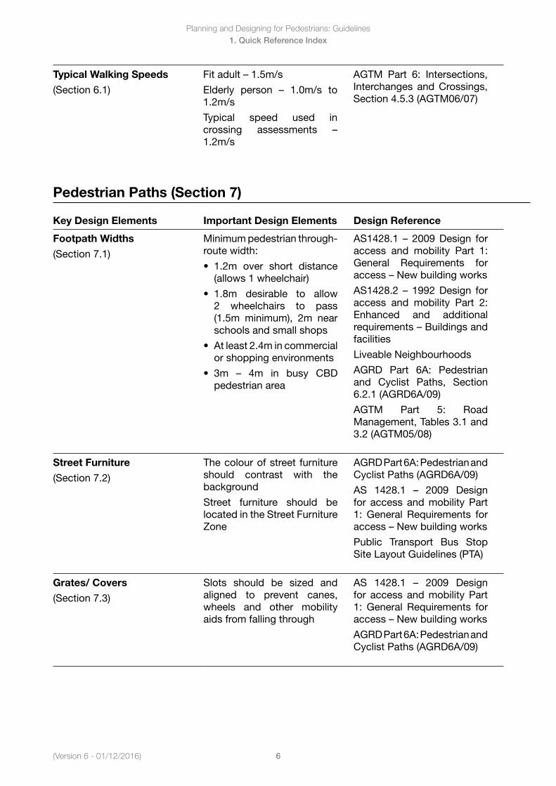
Typical Walking Speeds
(Section 6.1)
Fitadult–1.5m/s
Elderly person – 1.0m/s to1.2m/s
Typical speed used in crossing assessments –1.2m/s
AGTM Part 6: Intersections, Interchanges and Crossings, Section 4.5.3 (AGTM06/07)
Pedestrian Paths (Section 7)
Key Design Elements Important Design Elements Design Reference
Footpath Widths
(Section 7.1)
Minimum pedestrian through-route width:
• 1.2m over short distance(allows 1 wheelchair)
• 1.8m desirable to allow2 wheelchairs to pass (1.5m minimum), 2m near schools and small shops
• Atleast2.4mincommercial or shopping environments
• 3m – 4m in busy CBDpedestrian area
AS1428.1 – 2009Design foraccess and mobility Part 1: General Requirements for access–Newbuildingworks
AS1428.2 – 1992Design foraccess and mobility Part 2: Enhanced and additional requirements–Buildingsandfacilities
Liveable Neighbourhoods
AGRD Part 6A: Pedestrian and Cyclist Paths, Section 6.2.1 (AGRD6A/09)
AGTM Part 5: Road Management, Tables 3.1 and 3.2 (AGTM05/08)
Street Furniture
(Section 7.2)
The colour of street furniture should contrast with the background
Street furniture should be located in the Street Furniture Zone
AGRD Part 6A: Pedestrian and Cyclist Paths (AGRD6A/09)
AS 1428.1 – 2009 Designfor access and mobility Part 1: General Requirements for access–Newbuildingworks
Public Transport Bus Stop Site Layout Guidelines (PTA)
Grates/ Covers
(Section 7.3)
Slots should be sized and aligned to prevent canes, wheels and other mobility aids from falling through
AS 1428.1 – 2009 Designfor access and mobility Part 1: General Requirements for access–Newbuildingworks
AGRD Part 6A: Pedestrian and Cyclist Paths (AGRD6A/09)
Planning and Designing for Pedestrians: Guidelines
7(Version 6 - 01/12/16)
1. Quick Reference Index
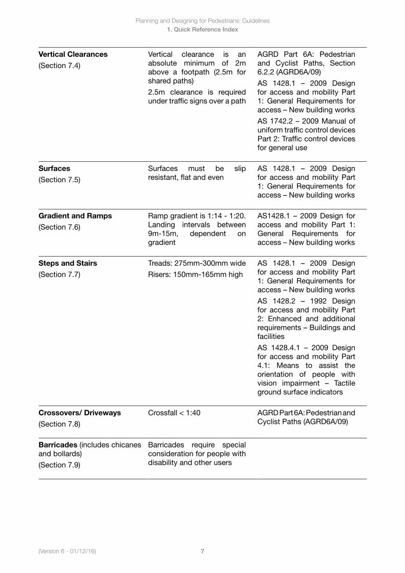
Vertical Clearances
(Section 7.4)
Vertical clearance is an absolute minimum of 2m above a footpath (2.5m for shared paths)
2.5m clearance is required under traffic signs over a path
AGRD Part 6A: Pedestrian and Cyclist Paths, Section 6.2.2 (AGRD6A/09)
AS 1428.1 – 2009 Designfor access and mobility Part 1: General Requirements for access–Newbuildingworks
AS1742.2–2009Manualofuniform traffic control devices Part 2: Traffic control devices for general use
Surfaces
(Section 7.5)
Surfaces must be slip resistant, flat and even
AS 1428.1 – 2009 Designfor access and mobility Part 1: General Requirements for access–Newbuildingworks
Gradient and Ramps
(Section 7.6)
Ramp gradient is 1:14 - 1:20. Landing intervals between 9m-15m, dependent on gradient
AS1428.1 – 2009Design foraccess and mobility Part 1: General Requirements for access–Newbuildingworks
Steps and Stairs
(Section 7.7)
Treads: 275mm-300mm wide
Risers: 150mm-165mm high
AS 1428.1 – 2009 Designfor access and mobility Part 1: General Requirements for access–Newbuildingworks
AS 1428.2 – 1992 Designfor access and mobility Part 2: Enhanced and additional requirements–Buildingsandfacilities
AS 1428.4.1 – 2009 Designfor access and mobility Part 4.1: Means to assist the orientation of people with vision impairment – Tactileground surface indicators
Crossovers/ Driveways
(Section 7.8)
Crossfall < 1:40 AGRD Part 6A: Pedestrian and Cyclist Paths (AGRD6A/09)
Barricades (includes chicanes and bollards)
(Section 7.9)
Barricades require special consideration for people with disability and other users
(Version 6 - 01/12/2016)
Planning and Designing for Pedestrians: Guidelines
8
1. Quick Reference Index
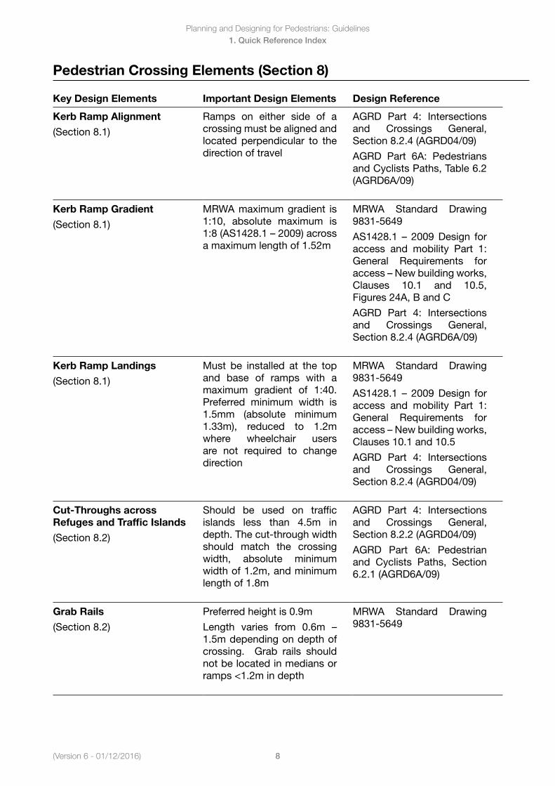
Pedestrian Crossing Elements (Section 8)
Key Design Elements Important Design Elements Design Reference
Kerb Ramp Alignment
(Section 8.1)
Ramps on either side of a crossing must be aligned and located perpendicular to the direction of travel
AGRD Part 4: Intersections and Crossings General, Section 8.2.4 (AGRD04/09)
AGRD Part 6A: Pedestrians and Cyclists Paths, Table 6.2 (AGRD6A/09)
Kerb Ramp Gradient
(Section 8.1)
MRWA maximum gradient is 1:10, absolute maximum is 1:8(AS1428.1–2009)acrossa maximum length of 1.52m
MRWA Standard Drawing 9831-5649
AS1428.1 – 2009Design foraccess and mobility Part 1: General Requirements for access–Newbuildingworks,Clauses 10.1 and 10.5, Figures 24A, B and C
AGRD Part 4: Intersections and Crossings General, Section 8.2.4 (AGRD6A/09)
Kerb Ramp Landings
(Section 8.1)
Must be installed at the top and base of ramps with a maximum gradient of 1:40. Preferred minimum width is 1.5mm (absolute minimum 1.33m), reduced to 1.2m where wheelchair users are not required to change direction
MRWA Standard Drawing 9831-5649
AS1428.1 – 2009Design foraccess and mobility Part 1: General Requirements for access–Newbuildingworks,Clauses 10.1 and 10.5
AGRD Part 4: Intersections and Crossings General, Section 8.2.4 (AGRD04/09)
Cut-Throughs across Refuges and Traffic Islands
(Section 8.2)
Should be used on traffic islands less than 4.5m in depth. The cut-through width should match the crossing width, absolute minimum width of 1.2m, and minimum length of 1.8m
AGRD Part 4: Intersections and Crossings General, Section 8.2.2 (AGRD04/09)
AGRD Part 6A: Pedestrian and Cyclists Paths, Section 6.2.1 (AGRD6A/09)
Grab Rails
(Section 8.2)
Preferred height is 0.9m
Length varies from 0.6m –1.5m depending on depth of crossing. Grab rails should not be located in medians or ramps <1.2m in depth
MRWA Standard Drawing 9831-5649
Planning and Designing for Pedestrians: Guidelines
9(Version 6 - 01/12/16)
1. Quick Reference Index
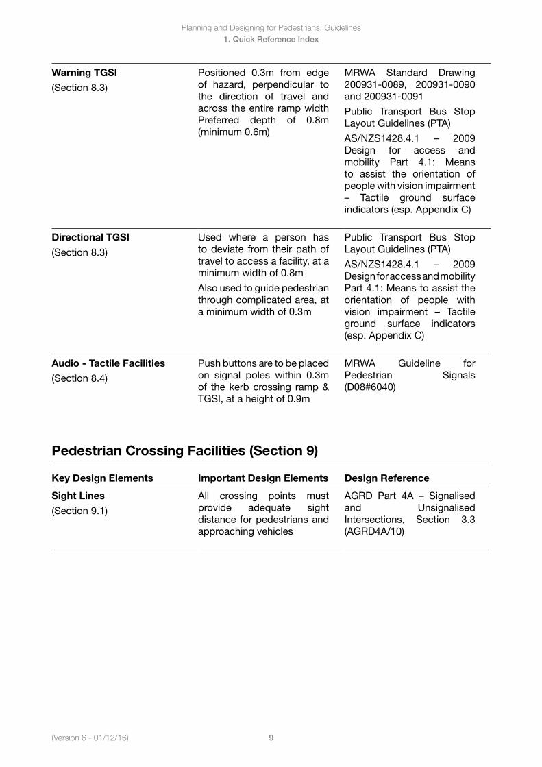
Warning TGSI
(Section 8.3)
Positioned 0.3m from edge of hazard, perpendicular to the direction of travel and across the entire ramp width Preferred depth of 0.8m (minimum 0.6m)
MRWA Standard Drawing 200931-0089, 200931-0090 and 200931-0091
Public Transport Bus Stop Layout Guidelines (PTA)
AS/NZS1428.4.1 – 2009Design for access and mobility Part 4.1: Means to assist the orientation of people with vision impairment – Tactile ground surfaceindicators (esp. Appendix C)
Directional TGSI
(Section 8.3)
Used where a person has to deviate from their path of travel to access a facility, at a minimum width of 0.8m
Also used to guide pedestrian through complicated area, at a minimum width of 0.3m
Public Transport Bus Stop Layout Guidelines (PTA)
AS/NZS1428.4.1 – 2009Design for access and mobility Part 4.1: Means to assist the orientation of people with vision impairment – Tactileground surface indicators (esp. Appendix C)
Audio - Tactile Facilities
(Section 8.4)
Push buttons are to be placed on signal poles within 0.3m of the kerb crossing ramp & TGSI, at a height of 0.9m
MRWA Guideline for Pedestrian Signals (D08#6040)
Pedestrian Crossing Facilities (Section 9)
Key Design Elements Important Design Elements Design Reference
Sight Lines
(Section 9.1)
All crossing points must provide adequate sight distance for pedestrians and approaching vehicles
AGRD Part 4A – Signalisedand Unsignalised Intersections, Section 3.3 (AGRD4A/10)
(Version 6 - 01/12/2016)
Planning and Designing for Pedestrians: Guidelines
10
1. Quick Reference Index
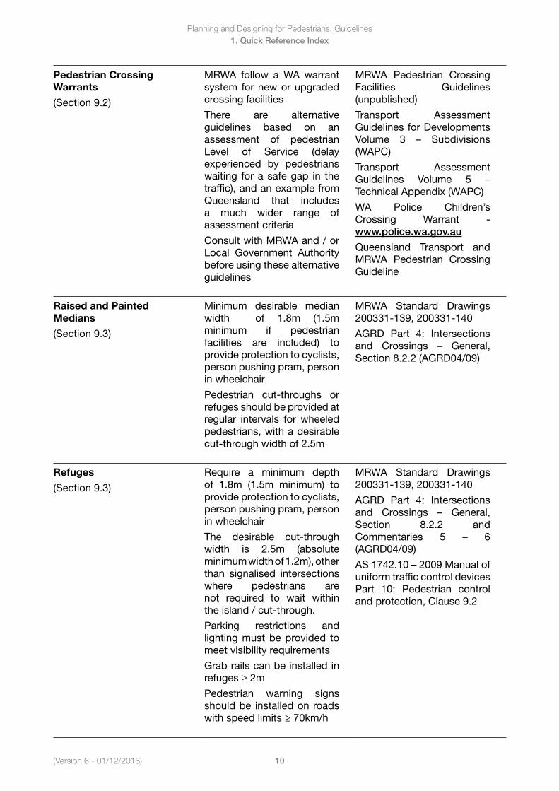
Pedestrian Crossing Warrants
(Section 9.2)
MRWA follow a WA warrant system for new or upgraded crossing facilities
There are alternative guidelines based on an assessment of pedestrian Level of Service (delay experienced by pedestrians waiting for a safe gap in the traffic), and an example from Queensland that includes a much wider range of assessment criteria
Consult with MRWA and / or Local Government Authority before using these alternative guidelines
MRWA Pedestrian Crossing Facilities Guidelines (unpublished)
Transport Assessment Guidelines for Developments Volume 3 – Subdivisions(WAPC)
Transport Assessment Guidelines Volume 5 –Technical Appendix (WAPC)
WA Police Children’s Crossing Warrant - www.police.wa.gov.au
Queensland Transport and MRWA Pedestrian Crossing Guideline
Raised and Painted Medians
(Section 9.3)
Minimum desirable median width of 1.8m (1.5m minimum if pedestrian facilities are included) to provide protection to cyclists, person pushing pram, person in wheelchair
Pedestrian cut-throughs or refuges should be provided at regular intervals for wheeled pedestrians, with a desirable cut-through width of 2.5m
MRWA Standard Drawings 200331-139, 200331-140
AGRD Part 4: Intersections and Crossings – General,Section 8.2.2 (AGRD04/09)
Refuges
(Section 9.3)
Require a minimum depth of 1.8m (1.5m minimum) to provide protection to cyclists, person pushing pram, person in wheelchair
The desirable cut-through width is 2.5m (absolute minimum width of 1.2m), other than signalised intersections where pedestrians are not required to wait within the island / cut-through.
Parking restrictions and lighting must be provided to meet visibility requirements
Grab rails can be installed in refuges ≥ 2m
Pedestrian warning signs should be installed on roads with speed limits ≥ 70km/h
MRWA Standard Drawings 200331-139, 200331-140
AGRD Part 4: Intersections and Crossings – General,Section 8.2.2 and Commentaries 5 – 6(AGRD04/09)
AS1742.10–2009Manualofuniform traffic control devices Part 10: Pedestrian control and protection, Clause 9.2
Planning and Designing for Pedestrians: Guidelines
11(Version 6 - 01/12/16)
1. Quick Reference Index
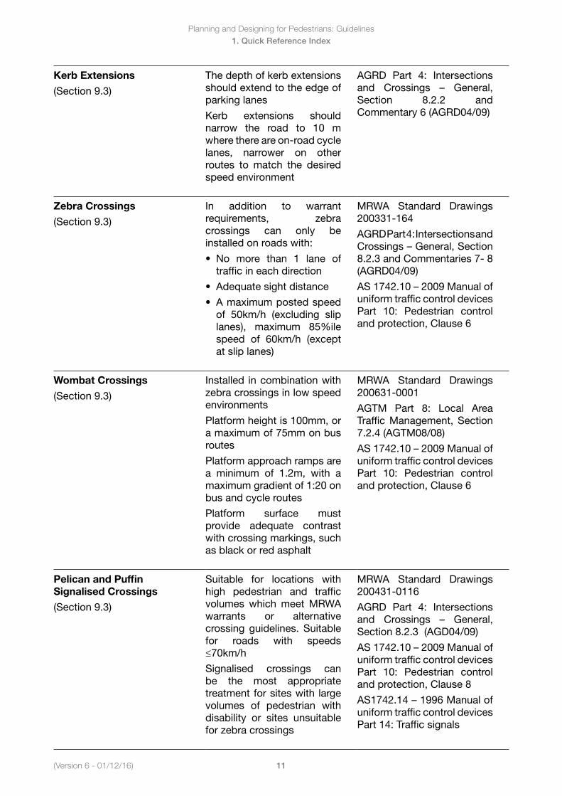
Kerb Extensions
(Section 9.3)
The depth of kerb extensions should extend to the edge of parking lanes
Kerb extensions should narrow the road to 10 m where there are on-road cycle lanes, narrower on other routes to match the desired speed environment
AGRD Part 4: Intersections and Crossings – General,Section 8.2.2 and Commentary 6 (AGRD04/09)
Zebra Crossings
(Section 9.3)
In addition to warrant requirements, zebra crossings can only be installed on roads with:
• No more than 1 lane oftraffic in each direction
• Adequatesightdistance
• Amaximumpostedspeedof 50km/h (excluding slip lanes), maximum 85%ile speed of 60km/h (except at slip lanes)
MRWA Standard Drawings 200331-164
AGRD Part 4: Intersections and Crossings–General,Section8.2.3 and Commentaries 7- 8 (AGRD04/09)
AS1742.10–2009Manualofuniform traffic control devices Part 10: Pedestrian control and protection, Clause 6
Wombat Crossings
(Section 9.3)
Installed in combination with zebra crossings in low speed environments
Platform height is 100mm, or a maximum of 75mm on bus routes
Platform approach ramps are a minimum of 1.2m, with a maximum gradient of 1:20 on bus and cycle routes
Platform surface must provide adequate contrast with crossing markings, such as black or red asphalt
MRWA Standard Drawings 200631-0001
AGTM Part 8: Local Area Traffic Management, Section 7.2.4 (AGTM08/08)
AS1742.10–2009Manualofuniform traffic control devices Part 10: Pedestrian control and protection, Clause 6
Pelican and Puffin Signalised Crossings
(Section 9.3)
Suitable for locations with high pedestrian and traffic volumes which meet MRWA warrants or alternative crossing guidelines. Suitable for roads with speeds ≤70km/h
Signalised crossings can be the most appropriate treatment for sites with large volumes of pedestrian with disability or sites unsuitable for zebra crossings
MRWA Standard Drawings 200431-0116
AGRD Part 4: Intersections and Crossings – General,Section 8.2.3 (AGD04/09)
AS1742.10–2009Manualofuniform traffic control devices Part 10: Pedestrian control and protection, Clause 8
AS1742.14–1996Manualofuniform traffic control devices Part 14: Traffic signals
(Version 6 - 01/12/2016)
Planning and Designing for Pedestrians: Guidelines
12
1. Quick Reference Index
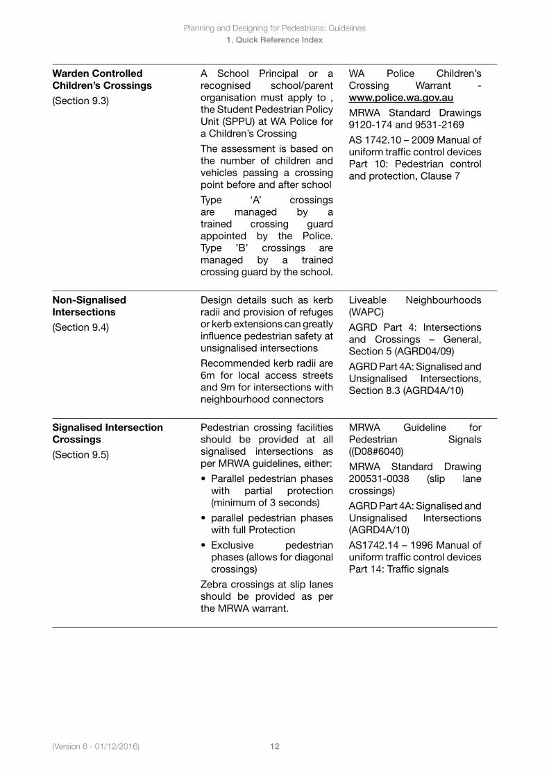
Warden Controlled Children’s Crossings
(Section 9.3)
A School Principal or a recognised school/parent organisation must apply to , the Student Pedestrian Policy Unit (SPPU) at WA Police for a Children’s Crossing
The assessment is based on the number of children and vehicles passing a crossing point before and after school
Type ‘A’ crossings are managed by a trained crossing guard appointed by the Police. Type ’B’ crossings are managed by a trained crossing guard by the school.
WA Police Children’s Crossing Warrant - www.police.wa.gov.au
MRWA Standard Drawings 9120-174 and 9531-2169
AS1742.10–2009Manualofuniform traffic control devices Part 10: Pedestrian control and protection, Clause 7
Non-Signalised Intersections
(Section 9.4)
Design details such as kerb radii and provision of refuges or kerb extensions can greatly influence pedestrian safety at unsignalised intersections
Recommended kerb radii are 6m for local access streets and 9m for intersections with neighbourhood connectors
Liveable Neighbourhoods (WAPC)
AGRD Part 4: Intersections and Crossings – General,Section 5 (AGRD04/09)
AGRD Part 4A: Signalised and Unsignalised Intersections, Section 8.3 (AGRD4A/10)
Signalised Intersection Crossings
(Section 9.5)
Pedestrian crossing facilities should be provided at all signalised intersections as per MRWA guidelines, either:
• Parallelpedestrianphases with partial protection (minimum of 3 seconds)
• parallel pedestrian phases with full Protection
• Exclusive pedestrianphases (allows for diagonal crossings)
Zebra crossings at slip lanes should be provided as per the MRWA warrant.
MRWA Guideline for Pedestrian Signals ((D08#6040)
MRWA Standard Drawing 200531-0038 (slip lane crossings)
AGRD Part 4A: Signalised and Unsignalised Intersections (AGRD4A/10)
AS1742.14–1996Manualofuniform traffic control devices Part 14: Traffic signals

Planning and Designing for Pedestrians: Guidelines
13(Version 6 - 01/12/16)
1. Quick Reference Index
Roundabouts
(Section 9.6)
Roundabouts should be designed with adequate entry curvature or deflection to reduce the speed of approaching vehicles
Recommended to locate kerb ramps and median cut-throughs at least 6m from the vehicle holding line (1 - 2 car lengths)
Where pedestrian volumes are high and there is speed environment ≤ 40km/h, zebra crossings can be considered
In some cases, signalised intersections may be more appropriate where pedestrian and traffic volumes are high, or there is a large proportion of children, elderly or pedestrians with disability
MRWA Standard Drawings 200331-197, 200331-201 and 200331-202
AGTM Part 6: Intersections, Interchanges and Crossings, Section 4 (AGTM06/07)
AGRD Part 4B: Roundabouts, Section 5.2 (AGRD4B/11)
Grade Separated Crossings
(Section 9.7)
Generally only provided along arterial roads with high traffic volumes and traffic speeds.
To encourage pedestrian patronage across grade separated facilities:
• Overpasses shouldbe constructed with a maximum change in level of 6.5m
• Underpasses shouldallow visibility along the length of the underpass and be constructed with a maximum change in level of 3.5m
AGTM Part 6: Intersections, Interchanges and Crossings, Table 8.1 (AGTM06/07)
AGRD Part 4C; Interchanges, Section 4.4 (AGRD4C/09)
AS5100.1 – 2004 Bridgedesign Part 1: Scope and general principles, Clause 9.1 and Clause 12
Designing Out Crime Planning Guidelines (WAPC)
Railway Crossings
(Section 9.8)
At grade railway crossings can be:
• Uncontrolled pedestrianmazes at non-electric railway crossings (at sites with adequate sight lines)
• Automatic lockable gatesat electric railway crossings
AS1742.7 – 2007Manual ofuniform traffic control devices Part 7: Railway crossings, Clause 6 and Appendix F
AGTM Part 6: Intersections, Interchanges and Crossings, Table 8.1 (AGTM06/07)
AGRD Part 4: Intersections and Crossings – General,Section 10.6 (AGRD04/09)
(Version 6 - 01/12/2016)
Planning and Designing for Pedestrians: Guidelines
14
1. Quick Reference Index
Pedestrian Guidance Measures (Section 10)
Key Design Elements Important Design Elements Design Reference
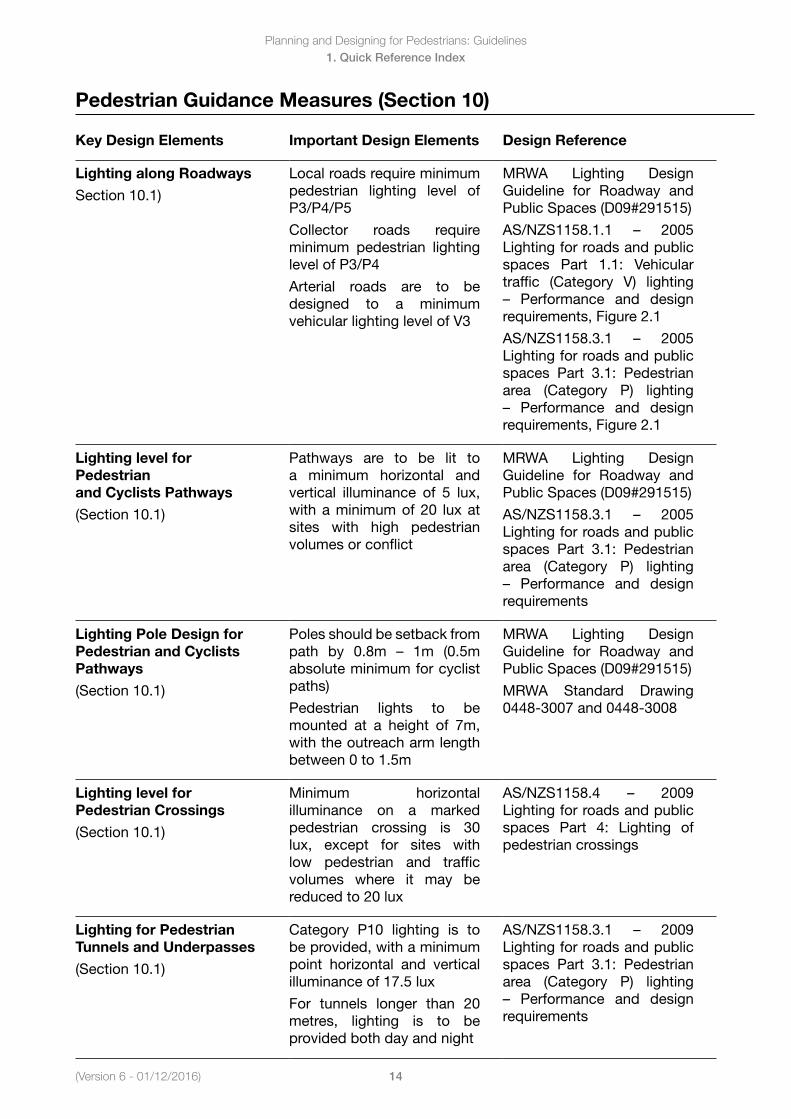
Lighting along Roadways
Section 10.1)
Local roads require minimum pedestrian lighting level of P3/P4/P5
Collector roads require minimum pedestrian lighting level of P3/P4
Arterial roads are to be designed to a minimum vehicular lighting level of V3
MRWA Lighting Design Guideline for Roadway and Public Spaces (D09#291515)
AS/NZS1158.1.1 – 2005Lighting for roads and public spaces Part 1.1: Vehicular traffic (Category V) lighting – Performance and designrequirements, Figure 2.1
AS/NZS1158.3.1 – 2005Lighting for roads and public spaces Part 3.1: Pedestrian area (Category P) lighting – Performance and designrequirements, Figure 2.1
Lighting level for Pedestrian and Cyclists Pathways
(Section 10.1)
Pathways are to be lit to a minimum horizontal and vertical illuminance of 5 lux, with a minimum of 20 lux at sites with high pedestrian volumes or conflict
MRWA Lighting Design Guideline for Roadway and Public Spaces (D09#291515)
AS/NZS1158.3.1 – 2005Lighting for roads and public spaces Part 3.1: Pedestrian area (Category P) lighting – Performance and designrequirements
Lighting Pole Design for Pedestrian and Cyclists Pathways
(Section 10.1)
Poles should be setback from path by 0.8m – 1m (0.5mabsolute minimum for cyclist paths)
Pedestrian lights to be mounted at a height of 7m, with the outreach arm length between 0 to 1.5m
MRWA Lighting Design Guideline for Roadway and Public Spaces (D09#291515)
MRWA Standard Drawing 0448-3007 and 0448-3008
Lighting level for Pedestrian Crossings
(Section 10.1)
Minimum horizontal illuminance on a marked pedestrian crossing is 30 lux, except for sites with low pedestrian and traffic volumes where it may be reduced to 20 lux
AS/NZS1158.4 – 2009Lighting for roads and public spaces Part 4: Lighting of pedestrian crossings
Lighting for Pedestrian Tunnels and Underpasses
(Section 10.1)
Category P10 lighting is to be provided, with a minimum point horizontal and vertical illuminance of 17.5 lux
For tunnels longer than 20 metres, lighting is to be provided both day and night
AS/NZS1158.3.1 – 2009Lighting for roads and public spaces Part 3.1: Pedestrian area (Category P) lighting – Performance and designrequirements
Planning and Designing for Pedestrians: Guidelines
15(Version 6 - 01/12/16)
1. Quick Reference Index
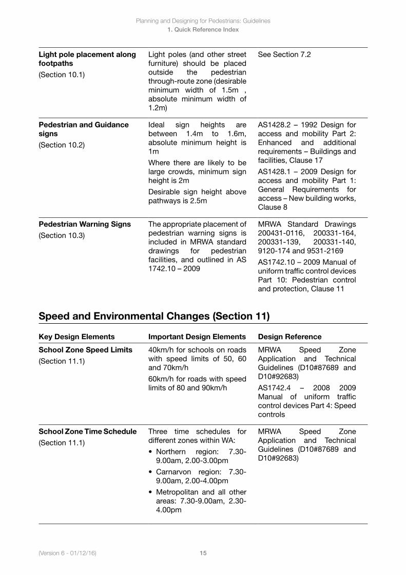
Light pole placement along footpaths
(Section 10.1)
Light poles (and other street furniture) should be placed outside the pedestrian through-route zone (desirable minimum width of 1.5m , absolute minimum width of 1.2m)
See Section 7.2
Pedestrian and Guidance signs
(Section 10.2)
Ideal sign heights are between 1.4m to 1.6m, absolute minimum height is 1m
Where there are likely to be large crowds, minimum sign height is 2m
Desirable sign height above pathways is 2.5m
AS1428.2 – 1992Design foraccess and mobility Part 2: Enhanced and additional requirements–Buildingsandfacilities, Clause 17
AS1428.1 – 2009Design foraccess and mobility Part 1: General Requirements for access–Newbuildingworks,Clause 8
Pedestrian Warning Signs
(Section 10.3)
The appropriate placement of pedestrian warning signs is included in MRWA standard drawings for pedestrian facilities, and outlined in AS 1742.10–2009
MRWA Standard Drawings 200431-0116, 200331-164, 200331-139, 200331-140, 9120-174 and 9531-2169
AS1742.10–2009Manualofuniform traffic control devices Part 10: Pedestrian control and protection, Clause 11
Speed and Environmental Changes (Section 11)
Key Design Elements Important Design Elements Design Reference
School Zone Speed Limits
(Section 11.1)
40km/h for schools on roads with speed limits of 50, 60 and 70km/h
60km/h for roads with speed limits of 80 and 90km/h
MRWA Speed Zone Application and Technical Guidelines (D10#87689 and D10#92683)
AS1742.4 – 2008 2009Manual of uniform traffic control devices Part 4: Speed controls
School Zone Time Schedule
(Section 11.1)
Three time schedules for different zones within WA:
• Northern region: 7.30-9.00am, 2.00-3.00pm
• Carnarvon region: 7.30-9.00am, 2.00-4.00pm
• Metropolitan and all otherareas: 7.30-9.00am, 2.30-4.00pm
MRWA Speed Zone Application and Technical Guidelines (D10#87689 and D10#92683)
(Version 6 - 01/12/2016)
Planning and Designing for Pedestrians: Guidelines
16
1. Quick Reference Index
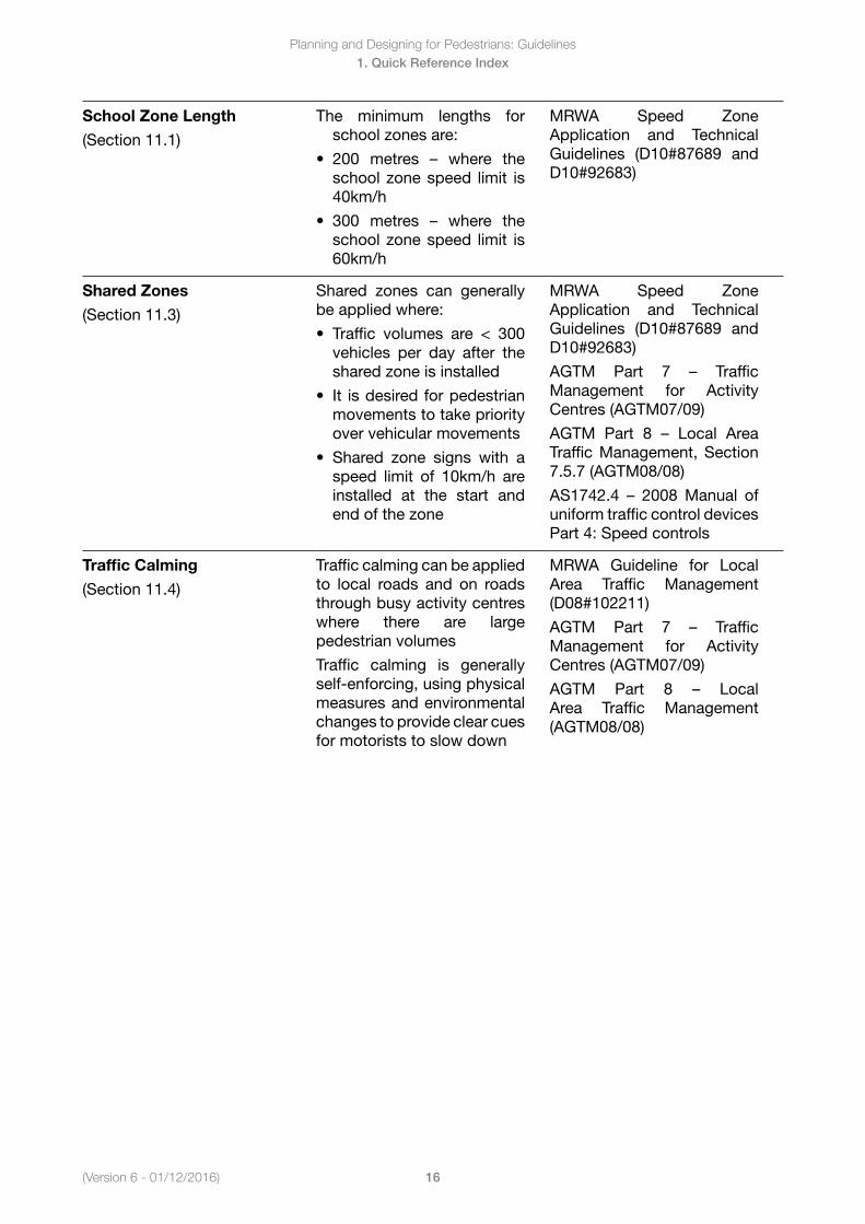
School Zone Length
(Section 11.1)
The minimum lengths for school zones are:
• 200 metres – where theschool zone speed limit is 40km/h
• 300 metres – where theschool zone speed limit is 60km/h
MRWA Speed Zone Application and Technical Guidelines (D10#87689 and D10#92683)
Shared Zones
(Section 11.3)
Shared zones can generally be applied where:
• Traffic volumes are < 300vehicles per day after the shared zone is installed
• It isdesiredforpedestrianmovements to take priority over vehicular movements
• Shared zone signs with aspeed limit of 10km/h are installed at the start and end of the zone
MRWA Speed Zone Application and Technical Guidelines (D10#87689 and D10#92683)
AGTM Part 7 – TrafficManagement for Activity Centres (AGTM07/09)
AGTM Part 8 – Local AreaTraffic Management, Section 7.5.7 (AGTM08/08)
AS1742.4 – 2008Manual ofuniform traffic control devices Part 4: Speed controls
Traffic Calming
(Section 11.4)
Traffic calming can be applied to local roads and on roads through busy activity centres where there are large pedestrian volumes
Traffic calming is generally self-enforcing, using physical measures and environmental changes to provide clear cues for motorists to slow down
MRWA Guideline for Local Area Traffic Management (D08#102211)
AGTM Part 7 – TrafficManagement for Activity Centres (AGTM07/09)
AGTM Part 8 – LocalArea Traffic Management (AGTM08/08)
Planning and Designing for Pedestrians: Guidelines
17(Version 6 - 01/12/16)
1. Quick Reference Index
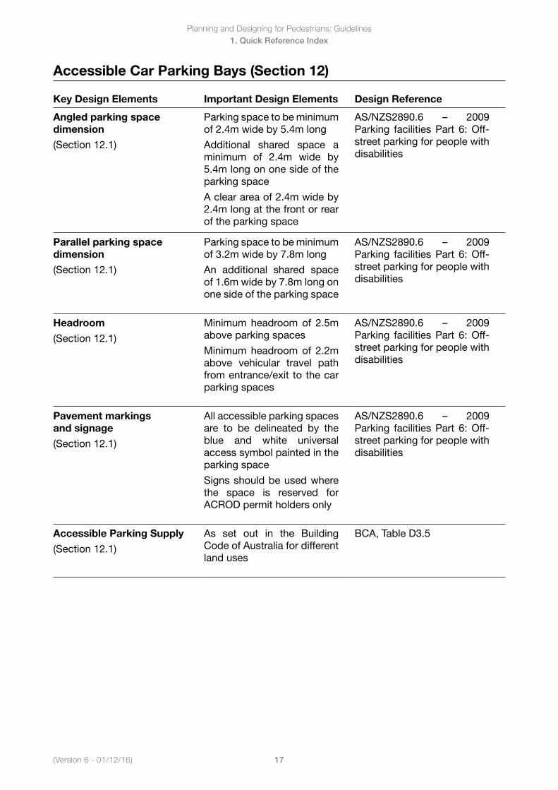
Accessible Car Parking Bays (Section 12)
Key Design Elements Important Design Elements Design Reference
Angled parking space dimension
(Section 12.1)
Parking space to be minimum of 2.4m wide by 5.4m long
Additional shared space a minimum of 2.4m wide by 5.4m long on one side of the parking space
A clear area of 2.4m wide by 2.4m long at the front or rear of the parking space
AS/NZS2890.6 – 2009Parking facilities Part 6: Off-street parking for people with disabilities
Parallel parking space dimension
(Section 12.1)
Parking space to be minimum of 3.2m wide by 7.8m long
An additional shared space of 1.6m wide by 7.8m long on one side of the parking space
AS/NZS2890.6 – 2009Parking facilities Part 6: Off-street parking for people with disabilities
Headroom
(Section 12.1)
Minimum headroom of 2.5m above parking spaces
Minimum headroom of 2.2m above vehicular travel path from entrance/exit to the car parking spaces
AS/NZS2890.6 – 2009Parking facilities Part 6: Off-street parking for people with disabilities
Pavement markings and signage
(Section 12.1)
All accessible parking spaces are to be delineated by the blue and white universal access symbol painted in the parking space
Signs should be used where the space is reserved for ACROD permit holders only
AS/NZS2890.6 – 2009Parking facilities Part 6: Off-street parking for people with disabilities
Accessible Parking Supply
(Section 12.1)
As set out in the Building Code of Australia for different land uses
BCA, Table D3.5
Planning and Designing for Pedestrians: Guidelines
18(Version 6 - 01/12/2016)
2. Setting the Scene
2. Setting the Scene
In this Section
2.1 Government Roles
2.1.1 State Government Roles
2.1.2 Local Government Roles
2.2 Strategic Context
2.2.1 International Charter for Walking
2.2.2 National Disability Strategy 2010 - 2020
2.2.3 HealthySpacesandPlaces
2.2.4 Walk WA: A Walking Strategy for Western Australia 2007 - 2020
2.2.5 Towards Zero (2008-2020)
2.2.6 RoadWise Program (since 1994)
2.2.7 Directions 2031 and Beyond (2010)
2.2.8 Activity Centres for Perth and Peel Policy
2.2.9 CountMeIn–DisabilityFutureDirections(2009)
2.2.10 Liveable Neighbourhoods (2007; updated 2009)
(Version 6 - 01/12/2016)
Planning and Designing for Pedestrians: Guidelines
19
2. Setting the Scene
2.1 Government Roles
Objective
To describe the roles of different government agencies involved in developing and promoting a walkable environment.
Key Points
State and Local Government have a range of interlinked roles and responsibilities.
Government organisations work together to raise the profile of walking and encourage walking at a strategic level as a healthy and sustainable transport mode.
2.1.1 State Government Roles
Department of Transport
The Department of Transport recognises that walking is a legitimate mode of transport to replace short car trips. The Department’s purpose is to ‘provide a safe, accessible, sustainable and efficient transport services, which promote economic prosperity and enhance the lifestyles of all.’ The Department was a joint partner of the Walk WA: A Walking Strategy for Western Australia 2007 – 2020 which sets out the vision that ‘By 2020, Western Australia will be a vibrant, safe, accessible place with a supportive walking environment where all West Australians enjoy walking for transport, health and recreation’.
www.transport.com.au
Department of Planning
Provides the strategic direction for planning policy and urban and regional development in Western Australia. Planning strategies and regulations influence the walkability of new developments. An example is Transit Orientated Development which seeks to concentrate activities within a walkable catchment area, encouraging people to walk within a centre to access a range of daily activities. Planning guidelines also influence the safety and attractiveness of streets, increasing interaction between buildings and adjacent paths to reduce crime and improve personal safety.
www.planning.wa.gov.au
Disability Services Commission
Is the State Government agency responsible for advancing opportunities, community participation and quality of life for people with disability through services and funding. As well as directly assisting people with disability, the Commission facilitates improved community access through education, information, publications and support. This includes guidance on planning for better access, from consultation and universal design to legislative requirements.
www.disability.wa.gov.au
Physical Activity Taskforce (Be Active WA)
Promoted under the Be Active WA banner, the Taskforce links programs and initiatives conducted by a range of government and community agencies. The Taskforce was formed in 2001 in response to the long-term decline of Western Australia physical activity levels. One of the major focus areas is the Walk WA strategy, developed in conjunction with State and Local Government. Walk WA provides a coordinated action plan to support more walking in our communities, leading to health, transport and environmental outcomes. www.beactive.wa.gov.au
Planning and Designing for Pedestrians: Guidelines
20(Version 6 - 01/12/2016)
2. Setting the Scene
Main Roads Western Australia (MRWA)
Is responsible for managing the state road network, which includes highways and freeways within Western Australia as well as ensuring safe and efficient road access for all road users including pedestrians. Main Roads responsibility includes the development of standard guidelines and detailed standard drawings for state and local road infrastructure.
Main Roads are the approving body for ensuring consistent application of signs and pavement markings on all roads in Western Australia. For this reason, Main Roads are involved in the design and approval process of pedestrian facilities on state and local road networks.
www.mainroads.wa.gov.au
Public Transport Authority (PTA)
Is responsible for Transperth and school bus services, regional coach services and maintenance and delivery of passenger and freight rail networks. Walking forms part of every public transport trip, highlighting the importance of planning accessible walking links to and from bus stops and train stations. As well, bus stop infrastructure is often located within footpath areas, requiring consideration of other footpath users as well as passenger access. PTA often coordinates the delivery of new bus or station infrastructure with Local Government and / or MRWA. PTA has developed guidelines on the design of bus stop infrastructure to provide a consistent approach across Western Australia, and have a long-term Bus Stop Accessibility Works Program. PTA is also responsible for providing safe pedestrian access across rail corridors, and assists with the development of shared path networks along these corridors.
www.pta.wa.gov.au
2.1.2 Local Government Roles
WA Local Government Association
The WA Local Government Association (WALGA) lobbies and negotiates on behalf of the 140 Local Governments in WA. As the peak lobbying and advocacy organisation, it has a strong influence on how policy decisions are made that affect the sector. Senior WALGA staff regularly consult with Ministers, politicians and senior bureaucrats and negotiate supplier agreements with senior executives of organisations with the capacity to deliver state-wide services.
www.walga.asn.au
Local Government
Councils are responsible for planning, constructing and maintaining much of the pedestrian network, specifically responsible for facilities on local distributor and access roads, and through many parks and reserves.
Councils are also responsible for approving the design of many new residential developments, and regeneration projects for town centres and recreational areas. The design and connectivity of these areas play a major role in the overall walkability of a neighbourhood.
Councils also implement TravelSmart projects promoting walking opportunities. This includes establishing walking groups, developing local walking plans and installing wayfinding signage. TravelSmart Officers work with schools to improve the safety and attractiveness of walk to school routes.
Check local government websites for Council policies, projects and technical specifications in each city or shire region.
Links to Local Government websites are available on the following page:
www.walga.asn.au/about_lg/council_websites

(Version 6 - 01/12/2016)
Planning and Designing for Pedestrians: Guidelines
21
2. Setting the Scene
2.2 Strategic Context
Objective
To describe the key policies and strategies at the International, National, State and Local Government level.
Key Points
Walking is promoted as a healthy and sustainable transport mode at all levels of government.
2.2.1 International Charter for WalkingThe International Charter for Walking was developed through the WALK21 international conference series in Melbourne, 2006. The Charter provides a common framework to help communities across the world refocus their existing policies, activities and relationships to create a culture where people choose to walk. Local, State and National Government organisations are encouraged to commit to the Charter, alongside individual community members.
The Charter focuses on the following strategic principles:
• Increasedinclusivemobility• Welldesignedandmanagedspacesandplacesforpeople• Improvedintegrationofnetworks• Supportiveland-useandspatialplanning• Reducedroaddanger• Lesscrimeandfearofcrime• Moresupportiveauthorities• Acultureofwalking
The Charter includes a practical list of actions that can be made in most communities, with authorities encouraged to add actions in response to specific local needs. A copy of the Charter can be found on the Walk 21 website www.walk21.com/charter
Planning and Designing for Pedestrians: Guidelines
22(Version 6 - 01/12/2016)
2. Setting the Scene
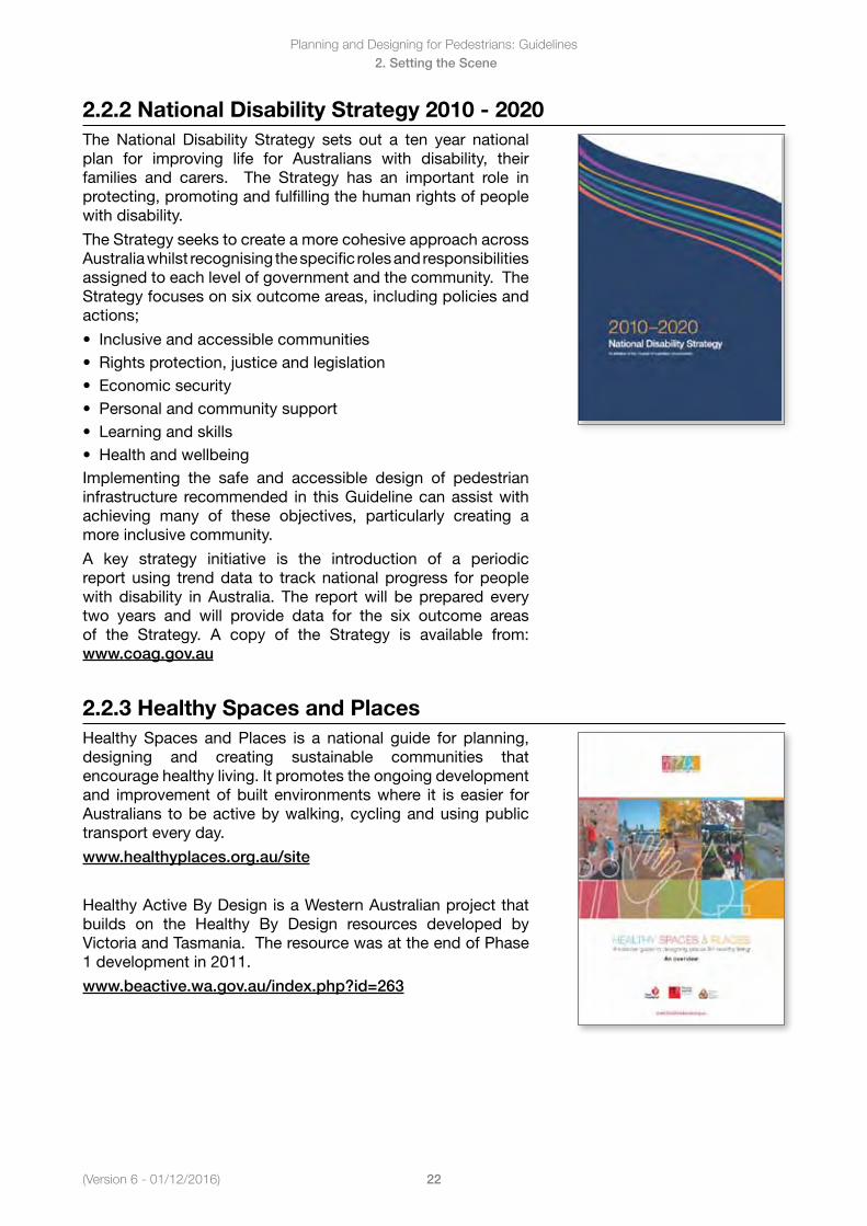
2.2.2 National Disability Strategy 2010 - 2020The National Disability Strategy sets out a ten year national plan for improving life for Australians with disability, their families and carers. The Strategy has an important role in protecting, promoting and fulfilling the human rights of people with disability.
The Strategy seeks to create a more cohesive approach across Australia whilst recognising the specific roles and responsibilities assigned to each level of government and the community. The Strategy focuses on six outcome areas, including policies and actions;
• Inclusiveandaccessiblecommunities• Rightsprotection,justiceandlegislation• Economicsecurity• Personalandcommunitysupport• Learningandskills• HealthandwellbeingImplementing the safe and accessible design of pedestrian infrastructure recommended in this Guideline can assist with achieving many of these objectives, particularly creating a more inclusive community.
A key strategy initiative is the introduction of a periodic report using trend data to track national progress for people with disability in Australia. The report will be prepared every two years and will provide data for the six outcome areas of the Strategy. A copy of the Strategy is available from: www.coag.gov.au
2.2.3 Healthy Spaces and PlacesHealthySpaces andPlaces is a national guide for planning,designing and creating sustainable communities that encourage healthy living. It promotes the ongoing development and improvement of built environments where it is easier for Australians to be active by walking, cycling and using public transport every day.
www.healthyplaces.org.au/site
HealthyActiveByDesignisaWesternAustralianprojectthatbuilds on the Healthy By Design resources developed byVictoria and Tasmania. The resource was at the end of Phase 1 development in 2011.
www.beactive.wa.gov.au/index.php?id=263
(Version 6 - 01/12/2016)
Planning and Designing for Pedestrians: Guidelines
23
2. Setting the Scene
2.2.4 Walk WA: A Walking Strategy for Western Australia 2007 - 2020
The Walk WA Strategy recognises the health, transport and environmental benefits of supporting more people to walk, more often throughout WA. People walk regularly for both recreation and transport, with walking being the most popular physical activity for adults in Western Australia.
People most commonly walk on local streets and paths, and the Strategy aims to improve these environments to enable more people to walk. The Strategy includes a detailed action plan for local and state government stakeholders, with short term targets to:
• Increasetheproportionofadultswhoreportwalking;• Increasethenumberofwalkingtripsperadultperweek.• Increasetheproportionofschool-agedchildrenwhowalkto
and from school.Improving existing or constructing new pedestrian facilities will play an important role in achieving the Walk WA objectives and targets.
www.beactive.wa.gov.au/index.php?id=350
2.2.5 Towards Zero (2008-2020)
Towards Zero is Western Australia’s road safety strategy for 2008-2020. The target is to see a reduction of 11,000 people killed or seriously injured on WA roads between 2008 and 2020.
The strategy outlines four cornerstones for a safe road system regarding road user behaviour, road infrastructure, speeds and vehicles. Of particular importance to pedestrian safety is the safe speeds cornerstone. The objective to prevent death and serious injury is ultimately to ensure impact speeds are within human tolerance, which is less than 30 km/h for a pedestrian and car conflict.
Towards Zero outlines five guiding principles to achieve a safe system:
• The limits of human performance – acknowledging thathumans make mistakes and that fallibility is essential.
• The limitsofhumantolerancetoviolent forces–seekingtokeep forces in collisions within our physical limits.
• Sharedresponsibility–takinganindividualandsharedroleinroad safety.
• Aforgivingroadsystem–aimingforan‘inherentlysafe’roadsystem designed such that when crashes do occur, deaths and serious injuries can be avoided.
• Increaseduseofpublic transport– reducing thenumberofvehicles on the road.
www.ors.wa.gov.au/Towards-Zero.aspx
Planning and Designing for Pedestrians: Guidelines
24(Version 6 - 01/12/2016)
2. Setting the Scene
2.2.6 RoadWise Program (since 1994)
The RoadWise Program is the WALGA’s Community Road Safety Program and has been in operation since 1994. The aim of RoadWise is to facilitate the involvement of Local Government and the community (through the community road safety network) in adopting and applying the safe system approach and specific initiatives of the Towards Zero strategy.
The Program consists of a community road safety network, supported by regional road safety officers who work with Local Government, RoadWise Committees, road safety partner agencies and the Community Road Safety Grants Program.
The RoadWise Program is supported by the Road Safety Council of WA and funded through the Road Trauma Trust Fund; which is one third of speed and red light camera infringements received in WA. The RoadWise Program is applied throughout the state with a Road Safety Officer based in each region.
www.walga.asn.au
www.roadwise.asn.au/
The Road Safety Around School Guidelines are particularly useful:
www.roadwise.asn.au/resources
2.2.7 Directions 2031 and Beyond (2010)
Directions 2031is a strategic plan for the future growth of the metropolitan Perth and Peel region. It provides a framework to guide the detailed planning and delivery of housing, infrastructure and services necessary to accommodate a population growth of between 35 and 40 percent between 2010 and 2031.
Directions 2031 identifies a connected city model as the preferred medium-density future growth scenario. This includes the following growth characteristics:
• Reducing energy dependency and greenhouse gasemissions.
• Planning and developing key public transport corridors,urban corridors and transit oriented developments to accommodate increased housing needs and encourage reduced vehicle use.
• Creating and enhancing transport and freight movementnetworks between activity centres and Industrial centres.
www.planning.wa.gov.au/publications/826.asp
(Version 6 - 01/12/2016)
Planning and Designing for Pedestrians: Guidelines
25
2. Setting the Scene
2.2.8 Activity Centres for Perth and Peel Policy
The main purpose of Activity Centre policy is to specify broad planning requirements for the planning and development of new activity centres and the redevelopment and renewal of existing centres in Perth and Peel. The policy outlines the hierarchy of centres for Perth and Peel, and identifies requirements such as walkable catchments, public transport access and residential catchments for the different centre categories.
The Activity Centre policy and Directions 2031 provide a consistent planned network of activity centres, aiming to evenly distribute jobs, services and amenities throughout Perth and Peel.
The policy also reflects the Western Australian Planning Commission’s (WAPC) intention to encourage and consolidate residential and commercial development in mixed-use activity centres so that they contribute to a balanced network.
www.planning.wa.gov.au/publications/1178.asp
2.2.9 Count Me In – Disability Future Directions (2009)
The Disability Future Directions strategy identifies 13 priorities to facilitate change in transport, housing, community attitudes, education, employment and technology over the next 15 to 20 years in Western Australia. The strategy seeks to develop a good future for people with disability, families and carers, and to benefit many other West Australians, such as elderly people.
One of the strategy priorities is ‘well-planned and accessible communities’. A key recommendation is for greater consultation with people with disability, family and carers in the planning and development of projects. Increased innovation in the development of accessible communities and universal housing design is another key focus.
www.disability.wa.gov.au/cmistrat.html
Planning and Designing for Pedestrians: Guidelines
26(Version 6 - 01/12/2016)
2. Setting the Scene
2.2.10 Liveable Neighbourhoods (2007; updated 2009)
Liveable Neighbourhoods was adopted by the WA Planning Commission as an alternative to previous subdivision policies. It proposes to achieve compact, better defined and more sustainable urban communities.
Among the principle aims of the policy document are:
• Toprovideforanurbanstructureofwalkableneighbourhoodsclustering to form towns of compatible mixed uses in order to reduce car dependence for access to employment, retail and community facilities
• Toensureaccesstoservicesandfacilitiesaredesignedforall users, including users with disabilities
• Toprovideforaccessgenerallybywayofaninterconnectednetwork of streets which facilitate safe, efficient and pleasant walking, cycling and driving.
www.planning.wa.gov.au/publications/ 919.asp
Planning and Designing for Pedestrians: Guidelines
27(Version 6 - 01/12/2016)
3. Standards and Guidelines
3. Standards and Guidelines
In this Section
3.1 Standards and Guidelines Summary
3.1.1 Standards and Guidelines for State Government Controlled Roads
3.1.2 Standards and Guidelines for Local Roads
3.1.3 Non-Standard Design
3.2 MRWA Standards and Guidelines
3.2.1 MRWA Online Reference Material
3.2.2 Relevant MRWA Policies and Guidelines
3.2.3 Relevant MRWA Standard Drawings
3.3 Other State Government Standards and Guidelines
3.3.1 Liveable Neighbourhoods (2007; updated 2009)
3.3.2 Transport Assessment Guidelines for Developments
3.3.3 Public Transport Bus Stop Layout Guidelines
3.4 Local Government Standards and Guidelines
3.4.1 Local Government
3.4.2 Road Safety Around Schools Guidelines
3.4.3 Walkability Audit Tool
3.5 Austroads Guide to Traffic Management and Guide to Road Design Series
3.5.1 Austroads Guide to Traffic Management Series
3.5.2 Austroads Guide to Road Design Series
3.6 Australian Standards
3.6.1 AS/NZS1158–LightingforRoadsandPublicSpacesSeries
3.6.2 AS1428–DesignforAccessandMobilitySeries
3.6.3 AS1742 Manual of Uniform Traffic Control Devices Series
3.6.4 AS2353 Pedestrian Push-Button Assemblies
3.6.5 AS2890 Parking Facilities Series
3.6.6 AS5100 Bridge Design Series
3.7 International Good Practice Examples
3.7.1 Manual for Streets, UK
3.7.2 Context Sensitive Solutions (CSS), Institute of Transportation Engineers 2010
(Version 6 - 01/12/2016)
Planning and Designing for Pedestrians: Guidelines
28
3. Standards and Guidelines
3.1 Standards and Guidelines Summary
Objective
To describe the range of standards and guidelines which are relevant for pedestrian infrastructure.
Key Points
There is a range of reference material which can be applicable for pedestrian facilities.
3.1.1 Standards and Guidelines for State Government Controlled Roads
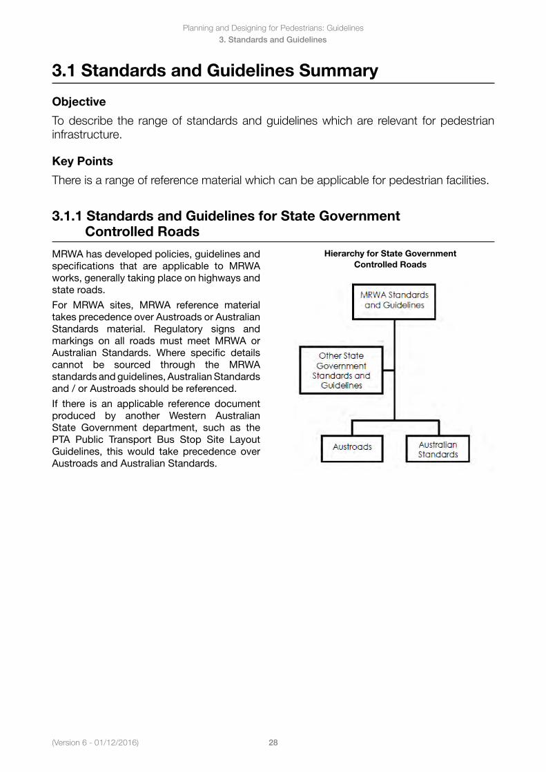
MRWA has developed policies, guidelines and specifications that are applicable to MRWA works, generally taking place on highways and state roads.
For MRWA sites, MRWA reference material takes precedence over Austroads or Australian Standards material. Regulatory signs and markings on all roads must meet MRWA or Australian Standards. Where specific details cannot be sourced through the MRWA standards and guidelines, Australian Standards and / or Austroads should be referenced.
If there is an applicable reference document produced by another Western Australian State Government department, such as the PTA Public Transport Bus Stop Site Layout Guidelines, this would take precedence over Austroads and Australian Standards.
Hierarchy for State Government Controlled Roads
Planning and Designing for Pedestrians: Guidelines
29(Version 6 - 01/12/2016)
3. Standards and Guidelines
3.1.2 Standards and Guidelines for Local Roads
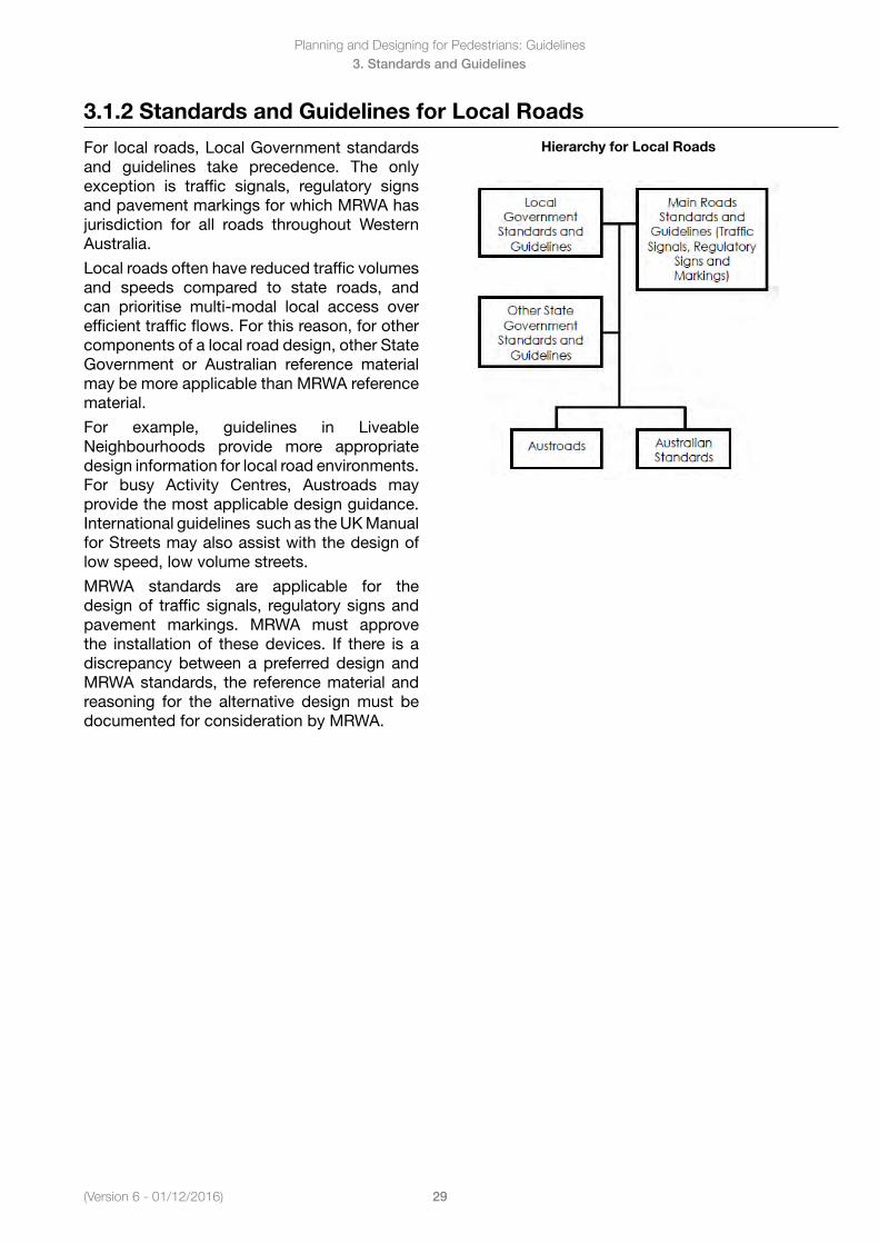
For local roads, Local Government standards and guidelines take precedence. The only exception is traffic signals, regulatory signs and pavement markings for which MRWA has jurisdiction for all roads throughout Western Australia.
Local roads often have reduced traffic volumes and speeds compared to state roads, and can prioritise multi-modal local access over efficient traffic flows. For this reason, for other components of a local road design, other State Government or Australian reference material may be more applicable than MRWA reference material.
For example, guidelines in Liveable Neighbourhoods provide more appropriate design information for local road environments. For busy Activity Centres, Austroads may provide the most applicable design guidance. International guidelines such as the UK Manual for Streets may also assist with the design of low speed, low volume streets.
MRWA standards are applicable for the design of traffic signals, regulatory signs and pavement markings. MRWA must approve the installation of these devices. If there is a discrepancy between a preferred design and MRWA standards, the reference material and reasoning for the alternative design must be documented for consideration by MRWA.
Hierarchy for Local Roads
(Version 6 - 01/12/2016)
Planning and Designing for Pedestrians: Guidelines
30
3. Standards and Guidelines
3.1.3 Non-Standard Design
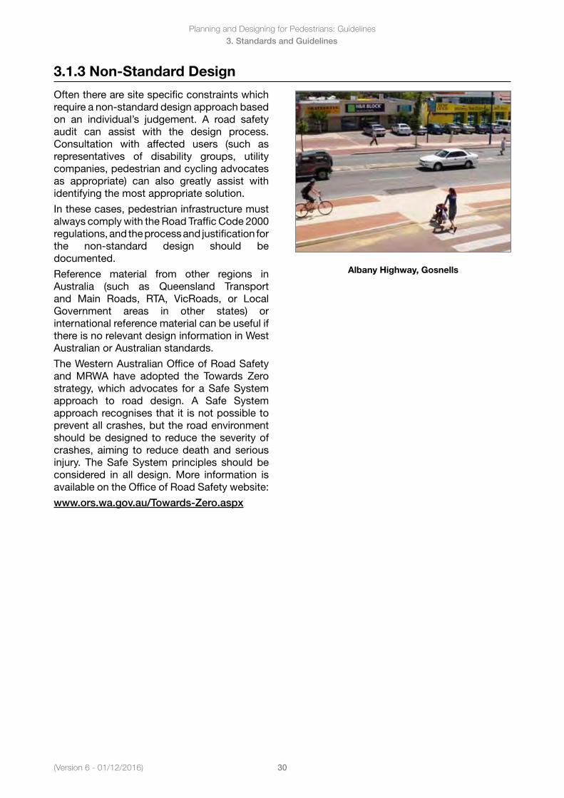
Often there are site specific constraints which require a non-standard design approach based on an individual’s judgement. A road safety audit can assist with the design process. Consultation with affected users (such as representatives of disability groups, utility companies, pedestrian and cycling advocates as appropriate) can also greatly assist with identifying the most appropriate solution.
In these cases, pedestrian infrastructure must always comply with the Road Traffic Code 2000 regulations, and the process and justification for the non-standard design should be documented.
Reference material from other regions in Australia (such as Queensland Transport and Main Roads, RTA, VicRoads, or Local Government areas in other states) or international reference material can be useful if there is no relevant design information in West Australian or Australian standards.
The Western Australian Office of Road Safety and MRWA have adopted the Towards Zero strategy, which advocates for a Safe System approach to road design. A Safe System approach recognises that it is not possible to prevent all crashes, but the road environment should be designed to reduce the severity of crashes, aiming to reduce death and serious injury. The Safe System principles should be considered in all design. More information is available on the Office of Road Safety website:
www.ors.wa.gov.au/Towards-Zero.aspx
Albany Highway, Gosnells
Planning and Designing for Pedestrians: Guidelines
31(Version 6 - 01/12/2016)
3. Standards and Guidelines
3.2 MRWA Standards and Guidelines
Objective
To outline MRWA standards and guidelines which are relevant for pedestrian infrastructure.
Key Points
MRWA have an extensive online library of policies, guidelines and standards.
3.2.1 MRWA Online Reference Material
MRWA standards, guidelines and other technical Information are available on the MRWAwebsite–www.mainroads.wa.gov.au
From the MRWA home page, following the links to:
• BuildingRoads(tabattopofhomepage)• Technical & Standards (in the list on left
hand side of web page)There is an extensive range of reference material available in this section. Follow the links through to the relevant reference area. For the design of pedestrian infrastructure, relevant information will generally be in the ‘Road and Traffic Engineering’ section, with specific pedestrian information in the ‘Geometric Design’ and ‘Traffic Management’ subsections.
To search through a list of available documents within each subsection, use the keyword search function at the top of the web page.
3.2.2 Relevant MRWA Policies and Guidelines
A number of MRWA policies and guidelines are referenced in this Manual. A list of these guidelines is provided below. These documents can be found on the MRWA website (unless otherwise noted).
• Draft Pavement Marking Guidelines (includes information on pedestrian crossing markings) (not available on the MRWA website)
• DisabilityAccessandInclusionPlan2012-2016• GuidelinesforAssessingPedestrianLevelofService• GuidelinetoPedestrianandCyclistFacilities(Doc#67-08-67)• GuidelineforPedestrianSignals(D08#6040)• GuidelinesforPedestrianCrossingWarrants–WorkingDocument(notavailableontheMRWA
website)• GuidelineforLocalAreaTrafficManagement(D08#102211)• SpeedZoningPolicyandGuidelines(D10#87684,D10#87689,D10#92683)
(Version 6 - 01/12/2016)
Planning and Designing for Pedestrians: Guidelines
32
3. Standards and Guidelines
3.2.3 Relevant MRWA Standard Drawings
A number of MRWA standard drawings are referenced in this Manual. These standard drawings can be found on the MRWA website, either by searching for a specific subject area or searching the list of all MRWA standard drawings:
www.mainroads.wa.gov.au
To find the complete list of MRWA standard drawings, from the MRWA home page follow the links to:
• BuildingRoads• Standards&Technical• MainRoadsDrawings:
• StandardContractDrawings(pavementmarkings,lightingandsigninstallation)or• GuidelineDrawings(Intersections,roundabouts,LATM)
To stay up to date with changes to MRWA standard drawings , subscribe to the MRWA automatic update service:
http://standards.mainroads.wa.gov.au
A list of the standard and guideline drawings referenced in this manual are provided below. It should be noted that drawings referenced in the Manual should only be viewed as an indicative layout; with specific site constraints to be considered for each individual design location. In addition, check the MRWA for any drawing updates occurring after the Manual publication.
Pedestrian Crossing Ramps
9831-5649 Ramp and Grab Rail Details
200931-0089 Directional Tactile Ground Surface Indicators - Ramp Type ‘A’ and ‘B’ Details
200931-0090DirectionalTactileGroundSurfaceIndicators–ModifiedCutThroughCornerTreatmentDetail
200931-0091DirectionalTactileGroundSurfaceIndicators–MedianGapDetails
Mid-Block Pedestrian Crossing Facilities
9120-174TrafficWardenControlled–SignsandPavementMarking
9531-2169AdvanceWarningFlashingSignals–SchoolCrossingSignalLayoutSignsandPavementMarkings
200331-139TypicalTreatmentforMedianIslands–PedestrianrefugeIsland(LaneWidth≤5.5m)
200331-140TypicalTreatmentforMedianIslands–PedestrianrefugeIsland(LaneWidth>5.5m)
200331-164 Signs and Line Marking for Pedestrian Zebra Crossing
200431-0116TrafficControlSignals–PuffinandPelicanCrossings–SignsandPavementMarking
200631-0001RoadHump–WombatCrossing
Lighting for Pedestrian Facilities
0448-3007 PSP Lighting Layout & Pole Schedule
0448-3008 PSP Lighting Light Pole Detail
Planning and Designing for Pedestrians: Guidelines
33(Version 6 - 01/12/2016)
3. Standards and Guidelines
Pedestrian Facilities at Intersections
The following drawings include some details on pedestrian facilities at different types of intersections.
200131-0084IntersectionsatGrade–Sheet4of8AustroadsRuralRightTurnType‘C’HighEntryAngle for Left Turn Slip Lane
200131-0085 Intersections atGrade – Sheet 5 of 8 – Free flow Left Turn Slip Lanes, AuxiliaryAcceleration Lanes & Seagull Island Alternative Dual Carriageway in Major Road
200131-0086 Signalised intersection with Double Left and Right Turn Lanes, Dual Carriageway in Both Lanes
200431-0065IntersectionsatGrade–Sheet7of8SignalisedIntersectionswithDoubleLeftTurnLanes, Right Turn Acceleration Lane, Dual Carriageway in Both Roads
200331-196SingleLaneRoundabouts–Step3of4
200331-201DualLaneRoundabouts–Step3of4
200331-141TypicalTreatmentforMedianIsland–IntersectionMedianIsland
2000331-142TypicalTreatmentforMedianIslands–LeftIn,LeftOutPartialClosure
200531-0038 Zebra Crossing at Slip Lane
200631-0002TypicalTreatmentforSeagullClosures–LeftTurnEntryandExitOnly
201131-0001TypicalTreatmentforEntryStatements–RaisedPavementatT-Junction
(Version 6 - 01/12/2016)
Planning and Designing for Pedestrians: Guidelines
34
3. Standards and Guidelines
3.3 Other State Government Standards and Guidelines
Objective
To outline other State Government standards and guidelines which are relevant for pedestrian infrastructure.
Key Points
Some other State Government authorities have developed design standards specific to road infrastructure.
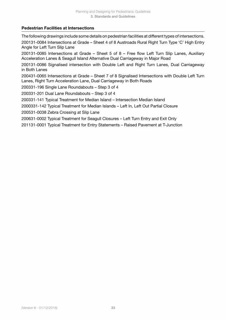
3.3.1 Liveable Neighbourhoods (2007; updated 2009)
The Liveable Neighbourhoods policy aims to achieve more compact, better defined and sustainable urban communities.
Liveable Neighbourhoods includes technical guidelines on the planning and design of walkable neighbourhoods. This includes recommendations on the street layout and footpath width.HoweveritshouldbenotedthedimensionsincludedinLiveable Neighbourhoods reflects the minimum width of the pedestrian through-route which should be provided along local roads. Local Government planning guidelines may require more generous footpath dimensions, and wider footpaths should be provided wherever possible. The dimensions in Liveable Neighbourhoods also assume all street furniture (including light poles and traffic signs) are located in the verge outside of the footpath width.
www.planning.wa.gov.au/publications/ 919.asp
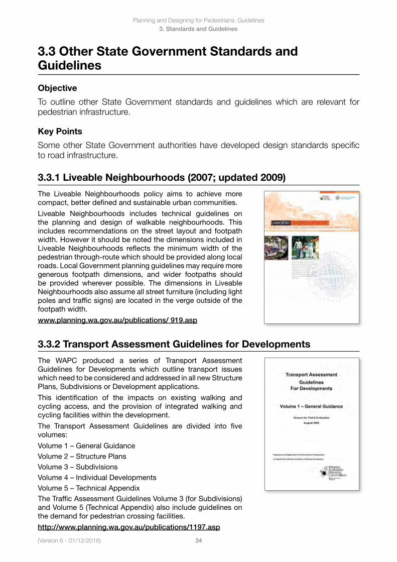
3.3.2 Transport Assessment Guidelines for Developments
The WAPC produced a series of Transport Assessment Guidelines for Developments which outline transport issues which need to be considered and addressed in all new Structure Plans, Subdivisions or Development applications.
This identification of the impacts on existing walking and cycling access, and the provision of integrated walking and cycling facilities within the development.
The Transport Assessment Guidelines are divided into five volumes:
Volume1–GeneralGuidanceVolume2–StructurePlansVolume3–SubdivisionsVolume4–IndividualDevelopmentsVolume5–TechnicalAppendixThe Traffic Assessment Guidelines Volume 3 (for Subdivisions) and Volume 5 (Technical Appendix) also include guidelines on the demand for pedestrian crossing facilities.
http://www.planning.wa.gov.au/publications/1197.asp
Planning and Designing for Pedestrians: Guidelines
35(Version 6 - 01/12/2016)
3. Standards and Guidelines
3.3.3 Public Transport Bus Stop Layout Guidelines
The Public Transport Authority (PTA) is responsible for the provision of all public transport services and facilities, and ensuring they comply with the requirements of the Disability Discrimination Act and the associated Disability Standards for Accessible Public Transport.
The objective of the Public Transport Bus Stop Layout Guidelines is to improve bus to bus stop accessibility by making the general bus stop area free of impediments that can act as mobility barriers. The Guidelines provides approved bus stop designs which include the application of tactile ground surface indicators (TGSIs) and wheelchair access at all new and existing bus stop locations.
There are other PTA Guidelines available that provide more detail on best practice approaches regarding planning public transport networks, prioritising bus services on transport networks and implementing traffic management devices along bus routes.
www.pta.wa.gov.au
(Version 6 - 01/12/2016)
Planning and Designing for Pedestrians: Guidelines
36
3. Standards and Guidelines
3.4 Local Government Standards and Guidelines
Objective
To outline Local Government standards and guidelines which are relevant for pedestrian infrastructure.
Key Points
Some Local Government Authorities have developed design standards specific to a local area.
3.4.1 Local Government
A number of Local Government Authorities have developed policies, guidelines or standard drawings which impact the design or use of pedestrian facilities. Examples include:
• Technicaldesignandconstructionnotesforroadinfrastructure• Saferdesignguidelinesfordesigningoutcrime(particularly
relevant for the location and lighting of pedestrian paths)• Technicaldesignandconstructionnotesforroadinfrastructure• Alfrescodiningpolicies,specifyingtheminimumclear-width
to be maintained for pedestrian access • Lighting policies, specifying minimum lighting levels for
different streets and paths• GuidelinesforconstructionworksaffectingfootpathsWhen working on local streets or reserves, always check with the Local Government Authority for relevant policies, guidelines or drawings. Much of this information is available on the Local Government Authority website.
3.4.2 Road Safety Around Schools Guidelines
The WA Local Government Association’s RoadWise Program has produced a comprehensive package of information, tools and advice to assist Local Governments and school communities to identify and address traffic management and road safety issues around schools.
Local Governments are encouraged to use the guidelines and distribute these to schools. Support and advice on using the guidelines is available from RoadWise Regional Road Safety Officers. The guidelines also aim to assist school communities in the identification of road safety issues in their school environment and develop strategies to address these issues.
www.roadwise.asn.au/
Planning and Designing for Pedestrians: Guidelines
37(Version 6 - 01/12/2016)
3. Standards and Guidelines
3.4.3 Walkability Audit Tool
The Walkability Audit Tool is a tool for use by officers of local government authorities, consultants and community groups to identify issues to improve pedestrian safety, accessibility and amenity. The tool can be used to help identify appropriate improvement measures and document the findings of the situation in an audit report to develop an action plan for the Council.
Walking audit tools are useful in two ways. The Tool flags what an auditor needs to check and provides a consistent audit framework to compare audit findings and outcomes. The document provides information on the steps to organise an audit and how to use the forms with supporting information when conducting an onsite audit.
www.transport.wa.gov.au/
(Version 6 - 01/12/2016)
Planning and Designing for Pedestrians: Guidelines
38
3. Standards and Guidelines
3.5 Austroads Guide to Traffic Management and Guide to Road Design Series
Objective
To outline the range of information available on pedestrian infrastructure throughout the new Austroads Guides.
Key Points
Reference and guidance measures to assist with planning and designing streets for pedestrians is included throughout the new Austroads Guides.
3.5.1 Austroads Guide to Traffic Management Series
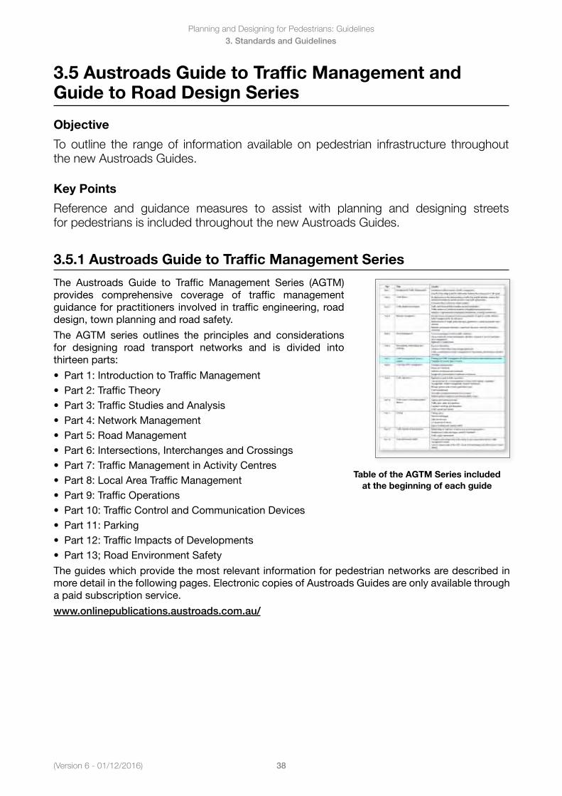
The Austroads Guide to Traffic Management Series (AGTM) provides comprehensive coverage of traffic management guidance for practitioners involved in traffic engineering, road design, town planning and road safety.
The AGTM series outlines the principles and considerations for designing road transport networks and is divided into thirteen parts:
• Part1:IntroductiontoTrafficManagement• Part2:TrafficTheory• Part3:TrafficStudiesandAnalysis• Part4:NetworkManagement• Part5:RoadManagement• Part6:Intersections,InterchangesandCrossings• Part7:TrafficManagementinActivityCentres• Part8:LocalAreaTrafficManagement• Part9:TrafficOperations• Part10:TrafficControlandCommunicationDevices• Part11:Parking• Part12:TrafficImpactsofDevelopments• Part13;RoadEnvironmentSafety
Table of the AGTM Series included at the beginning of each guide
The guides which provide the most relevant information for pedestrian networks are described in more detail in the following pages. Electronic copies of Austroads Guides are only available through a paid subscription service.
www.onlinepublications.austroads.com.au/
Planning and Designing for Pedestrians: Guidelines
39(Version 6 - 01/12/2016)
3. Standards and Guidelines
AGTM Part 3: Traffic Studies and Analysis (AGTM03/09)
Outlines the importance of traffic data and its analysis for transport planning and design. It provides guidance on the different types of traffic studies and surveys that can be undertaken, their use and application, and methods for traffic data collection and analysis.
Includes examples of pedestrian surveys in Appendix E.
AGTM Part 4: Network Management (AGTM04/09)
Discusses broader issues and considerations for managing road networks to provide effective traffic management for all road users.
Includes a brief summary of considerations for pedestrian networks and crossings, including discussion of different pedestrian characteristics in Section 4.7.
AGTM Part 5: Road Management (AGTM05/08)
Focuses on principles and issues for the management of mid-block traffic between major intersections. Includes guidance under the four key areas of access management, road space allocation, lane management and speed limits.
Includes a summary of road space considerations for pedestrians in Table 3.1 and 3.2.
(Version 6 - 01/12/2016)
Planning and Designing for Pedestrians: Guidelines
40
3. Standards and Guidelines
AGTM Part 6: Intersections, Interchanges and Crossings (AGTM06/07
Focuses on traffic management principles and issues and treatments related to intersections, interchanges and crossings.
It includes information and guidelines on factors that need to be considered in the selection of an appropriate type of intersection and in the functional design of intersections.
Includes a summary of issues for different road users (Table 3.3), discussion on pedestrians issues at roundabouts and typical walking speeds (Section 4.5.3), a summary of all road user requirements at arterial and local road signalised crossings (Table 5.2 and 5.3), and a more detailed discussion of pedestrian crossing facilities (Section 8).
AGTM Part 7: Traffic Management in Activity Centres (AGTM07/09)
Activity Centres are characterised by high levels of activity and interaction, especially by pedestrians. Activity centres often have a focus on ‘place making’ or the creation of vibrant hubs which bring people together. This guide addresses the need to balance providing for vehicular access and circulation, and providing for pedestrian, cyclist and public transport needs without compromising the functionality of a site.
The guide outlines operational and physical measures for all users on road networks through activity centres. The guide includes examples of activity centres around Australia where different approaches to lowering speeds and reducing conflict have been implemented. Specific details on providing for pedestrians are included in Section 3.8.
AGTM Part 8: Local Area Traffic Management (AGTM08/08)
Outlines principles, processes, issues and resource requirements for implementing Local Area Traffic Management schemes.
Includes design information and examples of a range of schemes and treatments. Lowering speed limits and discouraging unnecessary through-traffic assists with the safety and amenity of pedestrian networks.
Planning and Designing for Pedestrians: Guidelines
41(Version 6 - 01/12/2016)
3. Standards and Guidelines
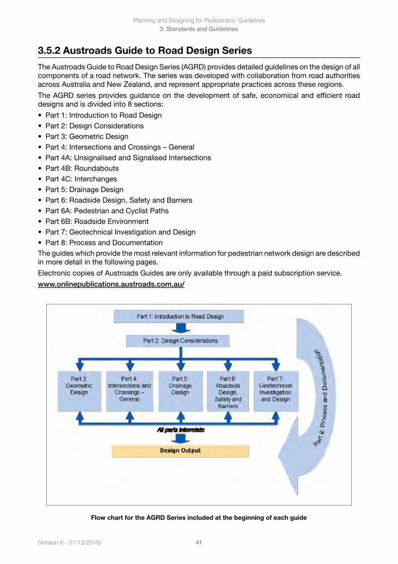
3.5.2 Austroads Guide to Road Design Series
The Austroads Guide to Road Design Series (AGRD) provides detailed guidelines on the design of all components of a road network. The series was developed with collaboration from road authorities across Australia and New Zealand, and represent appropriate practices across these regions.
The AGRD series provides guidance on the development of safe, economical and efficient road designs and is divided into 8 sections:
• Part1:IntroductiontoRoadDesign• Part2:DesignConsiderations• Part3:GeometricDesign• Part4:IntersectionsandCrossings–General• Part4A:UnsignalisedandSignalisedIntersections• Part4B:Roundabouts• Part4C:Interchanges• Part5:DrainageDesign• Part6:RoadsideDesign,SafetyandBarriers• Part6A:PedestrianandCyclistPaths• Part6B:RoadsideEnvironment• Part7:GeotechnicalInvestigationandDesign• Part8:ProcessandDocumentationThe guides which provide the most relevant information for pedestrian network design are described in more detail in the following pages.
Electronic copies of Austroads Guides are only available through a paid subscription service.
www.onlinepublications.austroads.com.au/
Flow chart for the AGRD Series included at the beginning of each guide
(Version 6 - 01/12/2016)
Planning and Designing for Pedestrians: Guidelines
42
3. Standards and Guidelines
AGRD Part 3: Geometric Design (AGRD03/10)
Covers geometric design elements such as operating speed, sight distance, horizontal and vertical geometry, and consideration of cross-section widths. This includes information on the recommended lane widths and dimensions for on-road cyclist and parking facilities.
The information in this guide generally replaces that which was previously provided in the Austroads Urban and Rural Road Design Guides (Austroads 2002b and Austroads 2003).
Includes information on assumptions used in sight distance assessments (Section 5.2.2) and Stopping Sight Distance calculations (Section 5.3).
AGRD Part 4: Intersections and Crossings General (AGRD04/09)
Provides design information on elements common to all at-grade intersections, such as design considerations for all road users, design process, choice of design vehicle, provision for public transport and property access.
This guide also provides detailed information on the selection and design of pedestrian mid-block crossing facilities (Section 8), including discussion on issues and considerations for different facilities in Commentaries 4 – 9). It also includesinformation on the design of railway crossings in Section 10.
AGRD Part 4A: Unsignalised and Signalised Crossings (AGRD4A/10)
Provides guidance on the detailed geometric design of all at-grade intersections (excluding roundabouts).
Includes information on sight distances at pedestrian crossings in Section 3.3.
Also includes some information on the design of kerb radii for specific design vehicles in Section 8.3 (these radii may not be appropriate for local road intersections).
Planning and Designing for Pedestrians: Guidelines
43(Version 6 - 01/12/2016)
3. Standards and Guidelines
AGRD Part 4B: Roundabouts (AGRD4B/11)
Provides guidance on the geometric design of roundabouts, including design principles, procedure, and guidelines to develop safe and efficient roundabout layouts. Includes a new design method for roundabouts that focuses on the entry curvature to achieve a reduction in vehicle approach speeds rather than applying the deflection method previously recommended.
Includes design consideration for pedestrians in Section 5.2, including information on pedestrian crossing assessments.
AGRD Part 4C: Interchanges (AGRD4C/09)
The focus of this part is the detailed geometric design of the grade separations, ramps and ramp terminals associated with interchanges, particularly with respect to cross-section, design speed, sight distance, horizontal and vertical alignment, sight distance and the layouts of ramp terminals at the freeway and at the minor road.
Includes a brief discussion on pedestrian grade separated crossings in Section 4.4, and on the provision for pedestrians and grade-separated interchanges in Section 13.
AGRD Part 6A: Pedestrian and Cyclist Paths (AGRD6A/09)
Covers the geometric design of all types of pedestrian and cycling paths. This includes the design of paths in road reserves, through parkland reserves, or beside rivers or coastal areas to provide safe and convenient routes and facilities for pedestrian and cyclists. The guide includes information on pedestrian space requirements and the principles of pedestrian network planning. It does not include any information related to pedestrian crossings, this is covered in AGTM Part 6 and AGRD Part 4, 4A, 4B and 4C.
(Version 6 - 01/12/2016)
Planning and Designing for Pedestrians: Guidelines
44
3. Standards and Guidelines
3.6 Australian Standards Series
Objective
To outline the relevant Australian Standards which include information on pedestrian infrastructure.
Key Points
Australian Standards outlines the minimum design requirements for pedestrian infrastructure.
Australian Standards
There are many Australian Standards (AS) that will be applicable when designing and constructing the pedestrian environment, including:
• AS/NZS1158Series–LightingforRoadsandPublicSpaces• AS1428Series–DesignforAccessandMobility• AS1742Series–ManualofUniformTrafficControlDevices• AS/NZS2890Series-ParkingFacilities• AS5100Series–BridgeDesignThe Australian Standards referenced in this manual are summarised in the following section.
Electronic copies of Australian Standards are only available through a paid subscription service.
www.standards.org.au/
3.6.1 AS/NZS1158 – Lighting for Roads and Public Spaces Series
AS/NZS1158.1.1 – 2005 (includes Amendment 1 2009)Part 1 - Vehicular traffic (Category V) lighting - Performance and design requirements
Lighting along arterial roads is generally required to meet the AS 1158.1.1 performance and design requirements. Reference should still be made to AS/NZS1158.3.1 to ensure lighting along adjacent footpaths meets the minimum pedestrian lighting requirements.
Planning and Designing for Pedestrians: Guidelines
45(Version 6 - 01/12/2016)
3. Standards and Guidelines
AS/NZS1158.3.1 – 2005 (includes Amendment 1 2008 and Amendment 2 2010)Part 3 - Pedestrian area (Category P) lighting - Performance and design requirements
This standard outlines the minimum lighting performance and design requirements along local roads, paths and through public spaces. Local governments may have additional policy and design requirements.
AS/NZS1158.4 – 2009Part 4: Lighting of pedestrian crossings
Outlines the minimum lighting performance and design requirements for pedestrian crossings, to ensure pedestrian are clearly visible to approaching motorists before entering and on a road crossing. All crossings likely to be used in the evenings and at night should meet the minimum lighting requirements to ensure the safety of pedestrians.
3.6.2 AS1428 – Design for Access and Mobility Series
AS1428.1 – 2009 (includes Amendment 1 2010)Part1:Generalrequirementsforaccess–newbuildingwork
A reference document that provides technical information on the design of facilities that will enable the minimal amount of access required by people with disability. This standard includes 80% of wheelchairs and 80% of users. Areas covered include specifications for providing:
• Circulationspaces• Kerbramps• Ramps,steps• Accessibletoilets• Signage
(Version 6 - 01/12/2016)
Planning and Designing for Pedestrians: Guidelines
46
3. Standards and Guidelines
AS1428.2 – 1992Part2:Enhancedandadditionalrequirements–Buildingsandfacilities
A reference document that provides technical information on the design of facilities that will enable access for people with disability including 90% of wheelchairs and 90% of users. This document also includes average and common reach ranges etc, for people with disability, providing valuable information for those designing non standard facilities to meet the needs of people of all ages and abilities.
AS/NZS1428.4.1 – 2009 (includes Amendment 1 2010)Part 4: Means to assist the orientation of people with visual impairment–Tactilegroundsurfaceindicators
This document provides information on the design and application of both hazard and directional tactile ground surface indicators (TGSI’s), within the pedestrian environment. It describes how these indicators compliment a system of other environmental guidance cues that assist people with a vision impairment to safely navigate around the community.
3.6.3 AS1742 Manual of Uniform Traffic Control Devices Series
AS1742.2 – 2009 (includes Amendment 1 2009)Part 2: Traffic control devices for general use
This Standard specifies requirements for regulatory and warning signs, pavement markings and other devices for general use on roads, and sets out the way they are applied at intersections and interchanges, between intersections, and at a number of specific situations. Includes information on vertical clearances underneath signs.
Planning and Designing for Pedestrians: Guidelines
47(Version 6 - 01/12/2016)
3. Standards and Guidelines
AS1742.4 – 2008 (includes Amendment 1 2009)Part 2: Speed controls
Includes information on traffic control devices used to reduce speed through particular environments (speed zones). This includes information on shared zones and school zone signage.
AS1742.7 – 2007 (includes Amendment 1 2007)Part 7: Railway crossings
This Standard specifies traffic control devices to be used to control and warn traffic at and in advance of railway crossings at grade. It specifies the way in which these devices are used to achieve the level of traffic control required for the safety of rail traffic and road users, including pedestrians.
Includes layout diagrams for a number of different pedestrian rail crossing options.
AS1742.10 – 2009Part 10: Pedestrian control and protection
Outlines requirements for the control and protection of pedestrians, including pedestrian and children’s crossings, mid-block pedestrian actuated traffic signals, pedestrian refuges and malls.
Information on temporary pedestrian facilities at roadworks is covered in S 1742.3, and information on shared pedestrian / bicycle paths is covered in AS 1742.9.
(Version 6 - 01/12/2016)
Planning and Designing for Pedestrians: Guidelines
48
3. Standards and Guidelines
AS1742.14 – 1996Part 14: Traffic signals
Sets out the requirements for the layout of signals and display aspects used at traffic signals.
Includes general information on pedestrian displays at traffic signals, and the placement of pedestrian push buttons.
3.6.4 AS2353 Pedestrian Push-Button Assemblies
Specifies the requirements for the design, construction and performance of pedestrian push-button assemblies and associated equipment, which are designed to facilitate the safe movement of pedestrians at locations controlled by traffic signals.
Includes requirements for the generation of audio-tactile signals, for use in conjunction with push-button assemblies, to assist pedestrians who are visually impaired.
3.6.5 AS2890 Parking Facilities Series
AS/NZS2890.6 – 2009Part 6: Off-street parking for people with disabilities
Outlines the minimum dimension and access requirements for accessible parking spaces.
The minimum supply rates for accessible parking spaces are outlined in the Building Code Australia.
Planning and Designing for Pedestrians: Guidelines
49(Version 6 - 01/12/2016)
3. Standards and Guidelines
3.6.6 AS5100 Bridge Design Series
AS5100.1 – 2004 (includes Amendment 1 2010)Part 1: Scope and general requirements
(This Standard is also designated as AUSTROADS publication AP-G15.1/04)
Provides information on the design of pedestrian bridges, including details on barriers to protect pedestrians and passing vehicles on roads or railways below pedestrian bridges.
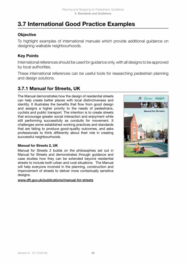
(Version 6 - 01/12/2016)
Planning and Designing for Pedestrians: Guidelines
50
3. Standards and Guidelines
3.7 International Good Practice Examples
Objective
To highlight examples of international manuals which provide additional guidance on designing walkable neighbourhoods.
Key Points
International references should be used for guidance only, with all designs to be approved by local authorities.
These international references can be useful tools for researching pedestrian planning and design solutions.
3.7.1 Manual for Streets, UK
The Manual demonstrates how the design of residential streets can help create better places with local distinctiveness and identity. It illustrates the benefits that flow from good design and assigns a higher priority to the needs of pedestrians, cyclists and public transport. The intention is to create streets that encourage greater social interaction and enjoyment while still performing successfully as conduits for movement. It challenges some established working practices and standards that are failing to produce good-quality outcomes, and asks professionals to think differently about their role in creating successful neighbourhoods.
Manual for Streets 2, UKManual for Streets 2 builds on the philosophies set out in Manual for Streets and demonstrates through guidance and case studies how they can be extended beyond residential streets to include both urban and rural situations. The Manual will help everyone involved in the planning, construction and improvement of streets to deliver more contextually sensitive designs.
www.dft.gov.uk/publications/manual-for-streets
Planning and Designing for Pedestrians: Guidelines
51(Version 6 - 01/12/2016)
3. Standards and Guidelines
3.7.2 Context Sensitive Solutions (CSS), Institute of Transportation Engineers 2010
The Context Sensitive Approach considers the total context within which a transportation project will exist. It is a collaborative, interdisciplinary approach involving all stakeholders to develop a transportation facility that fits its physical setting and preserves scenic, aesthetic, historic and environmental resources, while maintaining safety and mobility. In the past the design speed has been encouraged to be as high as is practical. The CSS recommends that the design speed become a function of the thoroughfare type and context (i.e. residential or commercial). Setting the design speed closer to the target speeds encourages operating speeds that are appropriate and enforceable.
www.ite.org/css/
Planning and Designing for Pedestrians: Guidelines
52(Version 6 - 01/12/2016)
4. Legislation and Regulations
4. Legislation and Regulations
In this Section
4.1 Disability Discrimination Act 1992
4.2 Road Traffic Code 2000
4.2.1 Pedestrian and Cyclist Definition
4.2.2 Paths Used by Pedestrians
4.2.3 Giving Way to Pedestrians
4.2.4 Non-Signalised Mid-Block Crossings
4.2.5 Signalised Crossings
4.2.6 Crossing the Carriageway at or near a Marked Crossing
4.2.7 Use of the Carriageway by Pedestrians at other than a Crossing
4.2.8 Access Prohibitions
4.2.9 Shared Zones
4.2.10 Railway Level Crossings
4.3 Main Roads Act 1930
4.3.1 Main Roads Act 1930
(Version 6 - 01/12/2016)
Planning and Designing for Pedestrians: Guidelines
53
4. Legislation and Regulations
4.1 Disability Discrimination Act 1992
Objective
To describe the Disability legislation pertaining to pedestrian infrastructure.
Key Points
There are legislative requirements that relate to infrastructure for pedestrians.
The Disability Discrimination Act provides uniform protection for everyone in Australia against discrimination based on disability. The Act ensures equality before the law and promotes acceptance within the community of the fundamental rights of people with disability.
Disability discrimination happens when people with disability are treated less fairly than people without disability. Disability discrimination also occurs when people are treated less fairly because they are relatives, friends, carers, co-workers or associates of a person with disability.
The Disability Discrimination Act makes it against the law to discriminate against someone if they have a disability in the following areas of life:
• Employment• Education• Accesstopremises(whichincludepublicfootpathsandwalkwaysundertheAct)• Provisionofgoods,servicesandfacilities• Accommodation• Buyingland• Activitiesofclubsandassociations• Sport• AdministrationofCommonwealthGovernmentlawsandprogramsWhere a person believes they have been discriminated against in breach of the Disability DiscriminationActtheycanmakeacomplainttotheAustralianHumanRightsCommissionaboutthe person, business or organisation alleged to have behaved in a discriminatory manner.
www.comlaw.gov.au/Details/C2010C00023
Planning and Designing for Pedestrians: Guidelines
54(Version 6 - 01/12/2016)
4. Legislation and Regulations
4.2 Road Traffic Code 2000Objective
To outline the current traffic regulations relevant to pedestrians.
Key Points
Regulations provide a legislative framework to control the movement of pedestrians and other road users.
Traffic laws that govern pedestrians and other road users in Western Australia are contained in the Road Traffic Code 2000. These laws are intended to provide safer conditions for all road users by regulating the way the road is used.
The rules outlined in the following pages are only a selection of all the regulations contained in the Road Traffic Code.
Rules relating specifically to pedestrian and cyclist behaviour are provided in Part 14. Rules relating to motorist behaviour where pedestrians are present are found throughout the Code. Specific rules on giving way at pedestrian crossings and in shared zones are provided in Part 7.
Note: The term “pedestrian crossing” used in the Road Traffic Code has been replaced by “zebra crossing” in this paper to avoid confusion with other pedestrian crossings.
www.slp.wa.gov.au
4.2.1 Pedestrian and Cyclist Definition
A pedestrian is defined as any person on foot, in a pram, or a person with disability in a unmotorised or motorised wheelchair, and includes:
• Apersonpushingaperambulatororwheelchair• Apersonwheelingabicycleorawheeledtoy,ifthepersoniscompletelydismountedfromthe
bicycle or wheeled toy• Apersoninoronawheeledrecreationaldeviceoramotorisedscooter• Apersonunder12yearsofageinoronawheeledtoyMore information on road rules for motorised scooters (or gophers) is available through the Department of Transport website:
Information for Gopher Users
A wheeled recreational device is defined as device used to transport a person which is propelled by human power or gravity only. The definition covers roller skates, skateboards and unicycles. All people using these devices are legally classified as pedestrians.
A motorised scooter is defined as a device with two or more wheels used by a single person and propelled by an electric motor, provided the motor is not capable of travelling at more 10km/h on level ground and the maximum motor output is 200 watts. All people using these devices are legally classified as pedestrians.
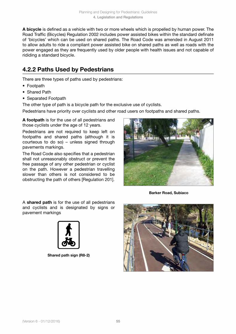
(Version 6 - 01/12/2016)
Planning and Designing for Pedestrians: Guidelines
55
4. Legislation and Regulations
A bicycle is defined as a vehicle with two or more wheels which is propelled by human power. The Road Traffic (Bicycles) Regulation 2002 includes power assisted bikes within the standard definate of ‘bicycles’ which can be used on shared paths. The Road Code was amended in August 2011 to allow adults to ride a compliant power assisted bike on shared paths as well as roads with the power engaged as they are frequently used by older people with health issues and not capable of rididing a standard bicycle.
4.2.2 Paths Used by Pedestrians
There are three types of paths used by pedestrians:
• Footpath• SharedPath• SeparatedFootpathThe other type of path is a bicycle path for the exclusive use of cyclists.
Pedestrians have priority over cyclists and other road users on footpaths and shared paths.
A footpath is for the use of all pedestrians and those cyclists under the age of 12 years.
Pedestrians are not required to keep left on footpaths and shared paths (although it is courteous to do so) – unless signed throughpavements markings.
The Road Code also specifies that a pedestrian shall not unreasonably obstruct or prevent the free passage of any other pedestrian or cyclist on the path. However a pedestrian travellingslower than others is not considered to be obstructing the path of others [Regulation 201].
Barker Road, Subiaco
A shared path is for the use of all pedestrians and cyclists and is designated by signs or pavement markings
Shared path sign (R8-2)
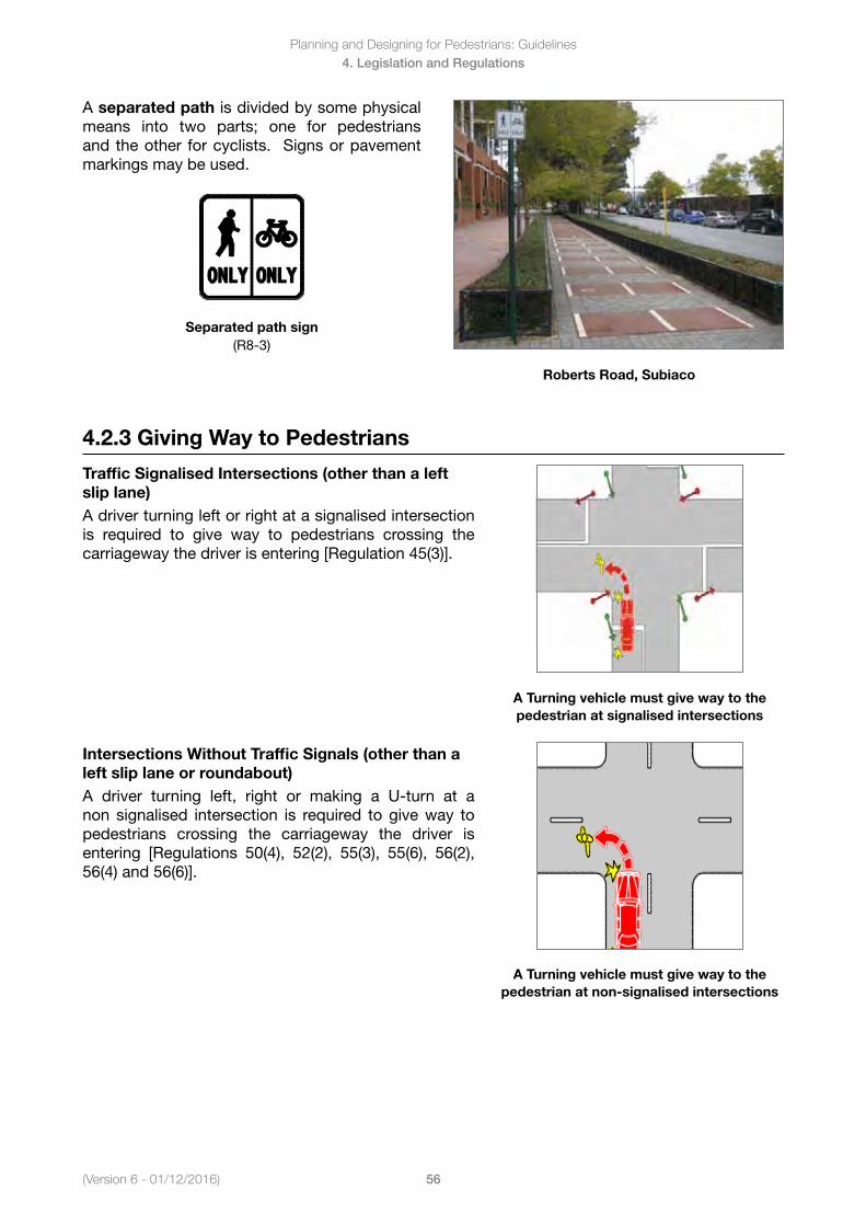
Planning and Designing for Pedestrians: Guidelines
56(Version 6 - 01/12/2016)
4. Legislation and Regulations
A separated path is divided by some physical means into two parts; one for pedestrians and the other for cyclists. Signs or pavement markings may be used.
Separated path sign(R8-3)
Roberts Road, Subiaco
4.2.3 Giving Way to Pedestrians
Traffic Signalised Intersections (other than a left slip lane)A driver turning left or right at a signalised intersection is required to give way to pedestrians crossing the carriageway the driver is entering [Regulation 45(3)].
A Turning vehicle must give way to the pedestrian at signalised intersections
Intersections Without Traffic Signals (other than a left slip lane or roundabout)A driver turning left, right or making a U-turn at a non signalised intersection is required to give way to pedestrians crossing the carriageway the driver is entering [Regulations 50(4), 52(2), 55(3), 55(6), 56(2), 56(4) and 56(6)].
A Turning vehicle must give way to the pedestrian at non-signalised intersections
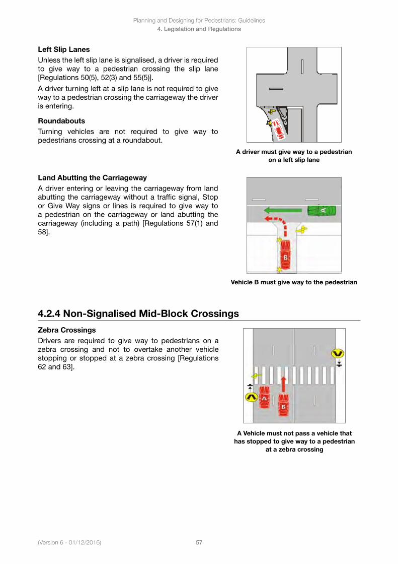
(Version 6 - 01/12/2016)
Planning and Designing for Pedestrians: Guidelines
57
4. Legislation and Regulations
Left Slip LanesUnless the left slip lane is signalised, a driver is required to give way to a pedestrian crossing the slip lane [Regulations 50(5), 52(3) and 55(5)].
A driver turning left at a slip lane is not required to give way to a pedestrian crossing the carriageway the driver is entering.
RoundaboutsTurning vehicles are not required to give way to pedestrians crossing at a roundabout.
A driver must give way to a pedestrian on a left slip lane
Land Abutting the CarriagewayA driver entering or leaving the carriageway from land abutting the carriageway without a traffic signal, Stop or Give Way signs or lines is required to give way to a pedestrian on the carriageway or land abutting the carriageway (including a path) [Regulations 57(1) and 58].
Vehicle B must give way to the pedestrian
4.2.4 Non-Signalised Mid-Block Crossings
Zebra CrossingsDrivers are required to give way to pedestrians on a zebra crossing and not to overtake another vehicle stopping or stopped at a zebra crossing [Regulations 62 and 63].
A Vehicle must not pass a vehicle that has stopped to give way to a pedestrian
at a zebra crossing
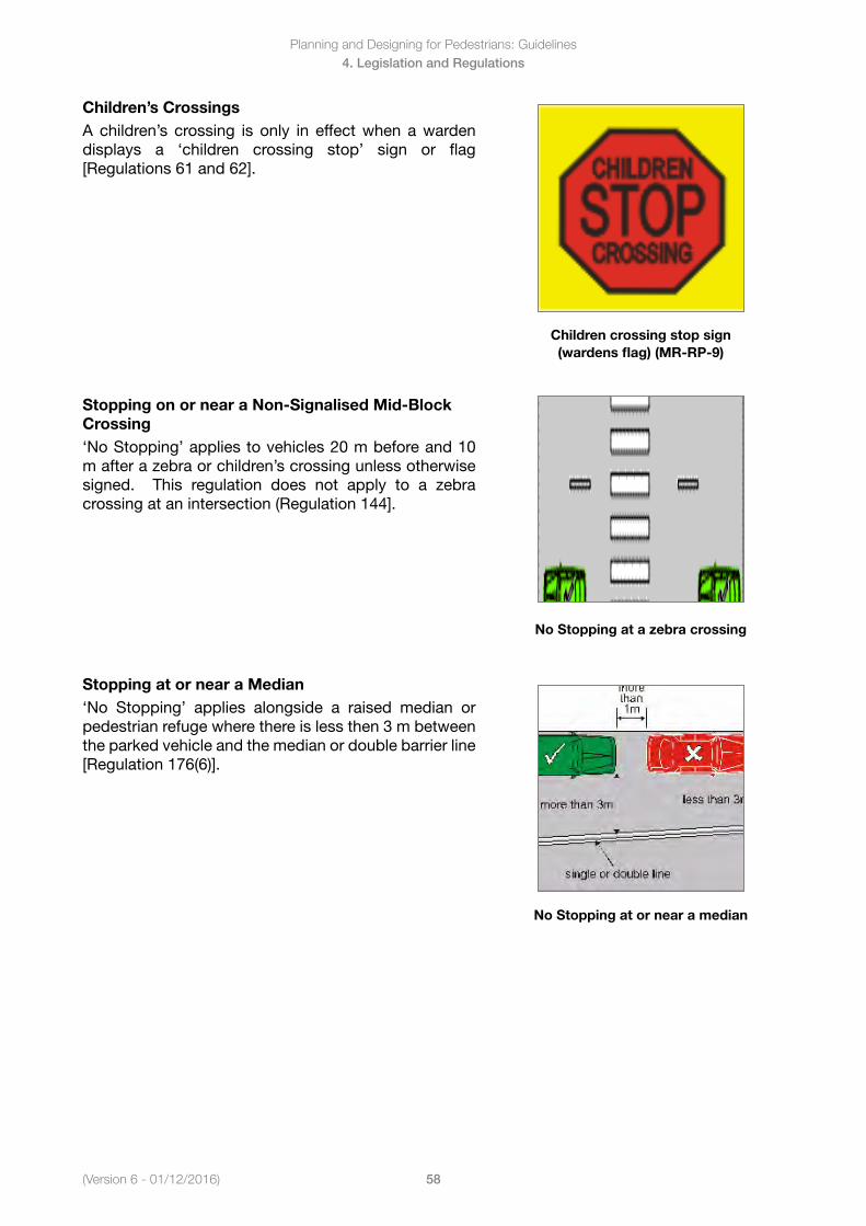
Planning and Designing for Pedestrians: Guidelines
58(Version 6 - 01/12/2016)
4. Legislation and Regulations
Children’s CrossingsA children’s crossing is only in effect when a warden displays a ‘children crossing stop’ sign or flag [Regulations 61 and 62].
Children crossing stop sign (wardens flag) (MR-RP-9)
Stopping on or near a Non-Signalised Mid-Block Crossing ‘No Stopping’ applies to vehicles 20 m before and 10 m after a zebra or children’s crossing unless otherwise signed. This regulation does not apply to a zebra crossing at an intersection (Regulation 144].
No Stopping at a zebra crossing
Stopping at or near a Median ‘No Stopping’ applies alongside a raised median or pedestrian refuge where there is less then 3 m between the parked vehicle and the median or double barrier line [Regulation 176(6)].
No Stopping at or near a median
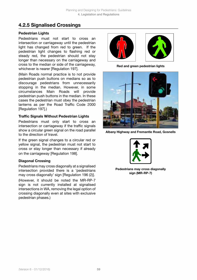
(Version 6 - 01/12/2016)
Planning and Designing for Pedestrians: Guidelines
59
4. Legislation and Regulations
4.2.5 Signalised Crossings
Pedestrian LightsPedestrians must not start to cross an intersection or carriageway until the pedestrian light has changed from red to green. If the pedestrian light changes to flashing red or steady red, the pedestrian should not stay longer than necessary on the carriageway and cross to the median or side of the carriageway, whichever is nearer [Regulation 197].
(Main Roads normal practice is to not provide pedestrian push buttons on medians so as to discourage pedestrians from unnecessarily stopping in the median. However, in somecircumstances Main Roads will provide pedestrian push buttons in the median. In these cases the pedestrian must obey the pedestrian lanterns as per the Road Traffic Code 2000 [Regulation 197].)
Traffic Signals Without Pedestrian LightsPedestrians must only start to cross an intersection or carriageway if the traffic signals show a circular green signal on the road parallel to the direction of travel.
If the green signal changes to a circular red or yellow signal, the pedestrian must not start to cross or stay longer than necessary if already on the carriageway [Regulation 198].
Diagonal CrossingPedestrians may cross diagonally at a signalised intersection provided there is a ‘pedestrians may cross diagonally’ sign [Regulation 196 (2)].
(However, it should be noted the MR-RP-7sign is not currently installed at signalised intersections in WA, removing the legal option of crossing diagonally even at sites with exclusive pedestrian phases.)
Red and green pedestrian lights
Albany Highway and Fremantle Road, Gosnells
Pedestrians may cross diagonally sign (MR-RP-7)
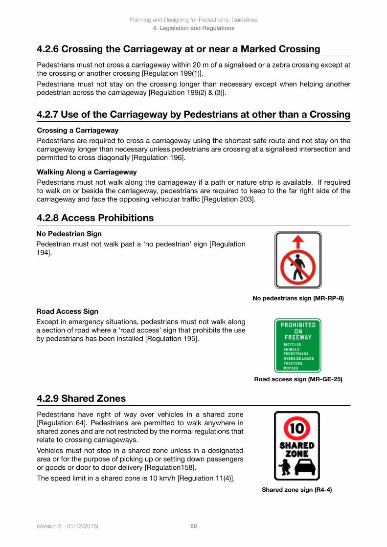
Planning and Designing for Pedestrians: Guidelines
60(Version 6 - 01/12/2016)
4. Legislation and Regulations
4.2.6 Crossing the Carriageway at or near a Marked Crossing
Pedestrians must not cross a carriageway within 20 m of a signalised or a zebra crossing except at the crossing or another crossing [Regulation 199(1)].
Pedestrians must not stay on the crossing longer than necessary except when helping another pedestrian across the carriageway [Regulation 199(2) & (3)].
4.2.7 Use of the Carriageway by Pedestrians at other than a Crossing
Crossing a CarriagewayPedestrians are required to cross a carriageway using the shortest safe route and not stay on the carriageway longer than necessary unless pedestrians are crossing at a signalised intersection and permitted to cross diagonally [Regulation 196].
Walking Along a CarriagewayPedestrians must not walk along the carriageway if a path or nature strip is available. If required to walk on or beside the carriageway, pedestrians are required to keep to the far right side of the carriageway and face the opposing vehicular traffic [Regulation 203].
4.2.8 Access Prohibitions
No Pedestrian Sign Pedestrian must not walk past a ‘no pedestrian’ sign [Regulation 194].
No pedestrians sign (MR-RP-8)
Road Access SignExcept in emergency situations, pedestrians must not walk along a section of road where a ‘road access’ sign that prohibits the use by pedestrians has been installed [Regulation 195].
Road access sign (MR-GE-25)
4.2.9 Shared Zones
Pedestrians have right of way over vehicles in a shared zone [Regulation 64]. Pedestrians are permitted to walk anywhere in shared zones and are not restricted by the normal regulations that relate to crossing carriageways.
Vehicles must not stop in a shared zone unless in a designated area or for the purpose of picking up or setting down passengers or goods or door to door delivery [Regulation158].
The speed limit in a shared zone is 10 km/h [Regulation 11(4)].
Shared zone sign (R4-4)
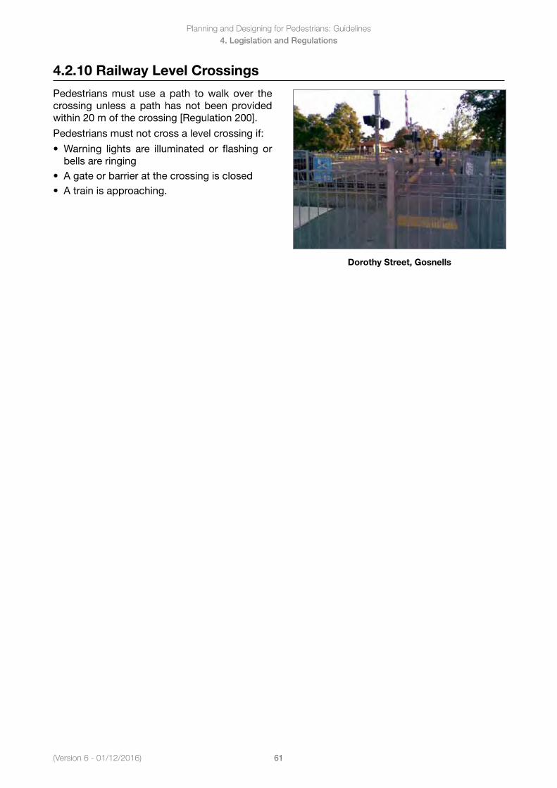
(Version 6 - 01/12/2016)
Planning and Designing for Pedestrians: Guidelines
61
4. Legislation and Regulations
4.2.10 Railway Level Crossings
Pedestrians must use a path to walk over the crossing unless a path has not been provided within 20 m of the crossing [Regulation 200].
Pedestrians must not cross a level crossing if:
• Warning lights are illuminated or flashing orbells are ringing
• Agateorbarrieratthecrossingisclosed• Atrainisapproaching.
Dorothy Street, Gosnells
Planning and Designing for Pedestrians: Guidelines
62(Version 6 - 01/12/2016)
4. Legislation and Regulations
4.3 Main Roads Act 1930
Objective
To outline the current legislation as it relates to the responsibility of MRWA and local government in respect to the provision and maintenance of roads and footpaths
Key Points
The legislation defines the types of road that MRWA are responsible for but also by implication identifies the responsibility for other roads to lie with local government.
MRWA may also carry out improvements on secondary roads but ongoing maintenance would be carried out by local government.
It also identifies MRWA’s responsibility for Traffic Signals and signs.
4.3.1 Main Roads Act 1930
The Main Roads Act 1930 sets out the responsibilities in respect of the construction, operation and maintenance of highways, main roads and secondary roads.
MRWA are therefore responsible for all works which take place on main roads and highways which would include any pedestrian facilitiesontheirnetwork.HowevertheactalsostatesthatMRWAmay carry out works on secondary roads following the approval of the relevant local government. The ongoing maintenance of these roads would however lie with the local authority.
The legislation also sets out the responsibility of MRWA in respect to the operation and maintenance of all Traffic Signals and signs.
The implication of this is that standards and guidelines relating to road construction must be to MRWA standards on highways and main roads, but to local government standards on other roads. However Traffic Signals and Signs should only beprovided to MRWA standards and guidelines.
Planning and Designing for Pedestrians: Guidelines
63(Version 6 - 01/12/2016)
5. Land Use Planning
5. Land Use Planning
5.1 Land Use Planning
5.1.1 Pedestrian Network Planning
5.1.2 Pedestrian Safety and Amenity
5.1.3 Urban Form
5.1.4 Development Scale
5.1.5 Access to Public Transport
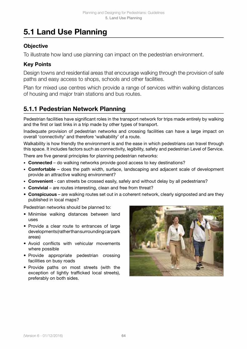
(Version 6 - 01/12/2016)
Planning and Designing for Pedestrians: Guidelines
64
5. Land Use Planning
5.1 Land Use Planning
Objective
To illustrate how land use planning can impact on the pedestrian environment.
Key Points
Design towns and residential areas that encourage walking through the provision of safe paths and easy access to shops, schools and other facilities.
Plan for mixed use centres which provide a range of services within walking distances of housing and major train stations and bus routes.
5.1.1 Pedestrian Network Planning
Pedestrian facilities have significant roles in the transport network for trips made entirely by walking and the first or last links in a trip made by other types of transport.
Inadequate provision of pedestrian networks and crossing facilities can have a large impact on overall ‘connectivity’ and therefore ‘walkability’ of a route.
Walkability is how friendly the environment is and the ease in which pedestrians can travel through this space. It includes factors such as connectivity, legibility, safety and pedestrian Level of Service.
There are five general principles for planning pedestrian networks:
• Connected – do walking networks provide good access to key destinations?• Comfortable–doesthepathwidth,surface, landscapingandadjacentscaleofdevelopment
provide an attractive walking environment? • Convenient - can streets be crossed easily, safely and without delay by all pedestrians?• Convivial – are routes interesting, clean and free from threat?• Conspicuous –arewalkingroutessetoutinacoherentnetwork,clearlysignpostedandarethey
published in local maps?
Pedestrian networks should be planned to:
• Minimise walking distances between landuses
• Provide a clear route to entrances of largedevelopments (rather than surrounding car park areas)
• Avoid conflicts with vehicular movementswhere possible
• Provide appropriate pedestrian crossingfacilities on busy roads
• Provide paths on most streets (with theexception of lightly trafficked local streets), preferably on both sides.
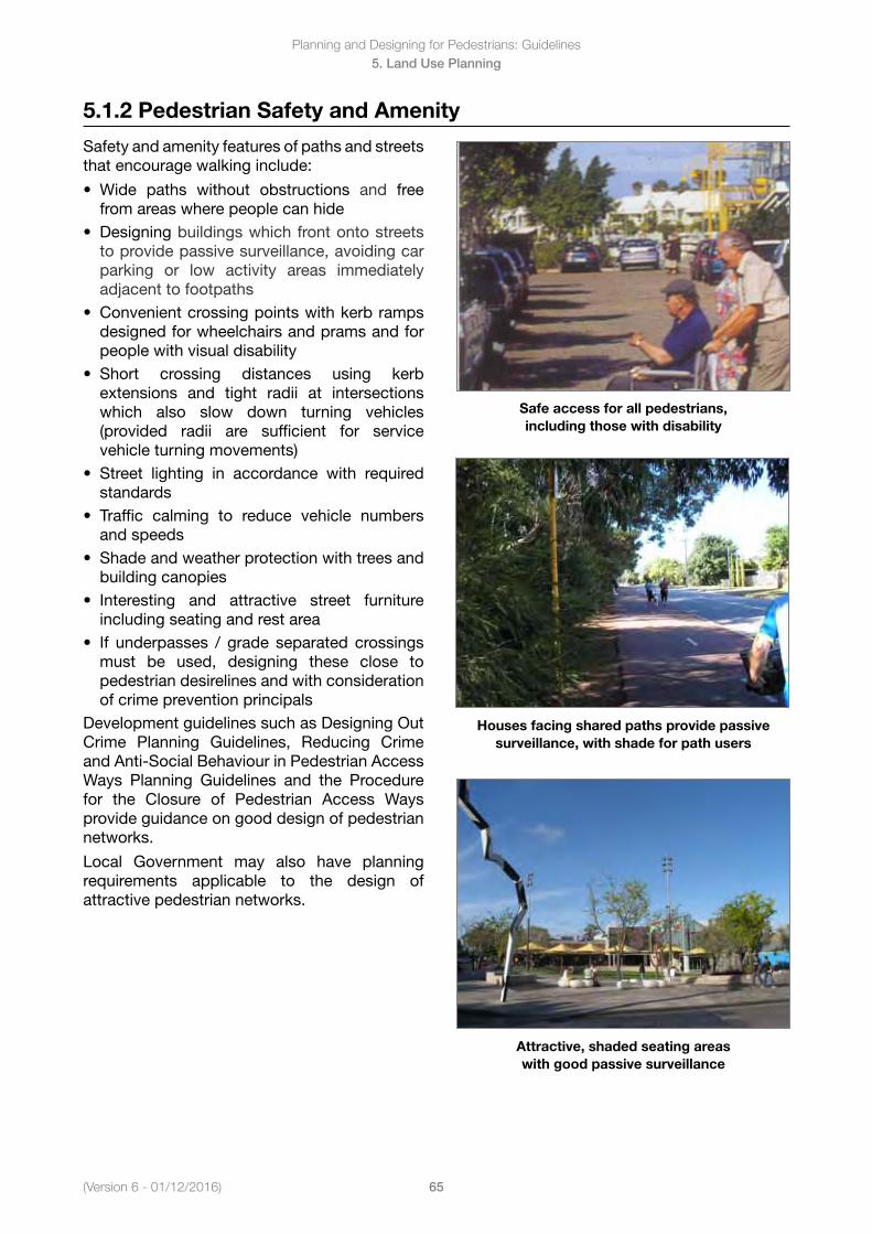
Planning and Designing for Pedestrians: Guidelines
65(Version 6 - 01/12/2016)
5. Land Use Planning
5.1.2 Pedestrian Safety and Amenity
Safety and amenity features of paths and streets that encourage walking include:
• Wide paths without obstructions and freefrom areas where people can hide
• Designing buildings which front onto streetsto provide passive surveillance, avoiding carparking or low activity areas immediatelyadjacent to footpaths
• Convenientcrossingpointswithkerbrampsdesigned for wheelchairs and prams and forpeople with visual disability
• Short crossing distances using kerbextensions and tight radii at intersectionswhich also slow down turning vehicles(provided radii are sufficient for servicevehicle turning movements)
• Street lighting in accordance with requiredstandards
• Traffic calming to reduce vehicle numbersand speeds
• Shadeandweatherprotectionwithtreesandbuilding canopies
• Interesting and attractive street furnitureincluding seating and rest area
• If underpasses / grade separated crossingsmust be used, designing these close topedestrian desirelines and with considerationof crime prevention principals
Development guidelines such as Designing Out Crime Planning Guidelines, Reducing Crime and Anti-Social Behaviour in Pedestrian Access Ways Planning Guidelines and the Procedure for the Closure of Pedestrian Access Ways provide guidance on good design of pedestrian networks.
Local Government may also have planning requirements applicable to the design of attractive pedestrian networks.
Safe access for all pedestrians, including those with disability
Houses facing shared paths provide passive surveillance, with shade for path users
Attractive, shaded seating areas with good passive surveillance
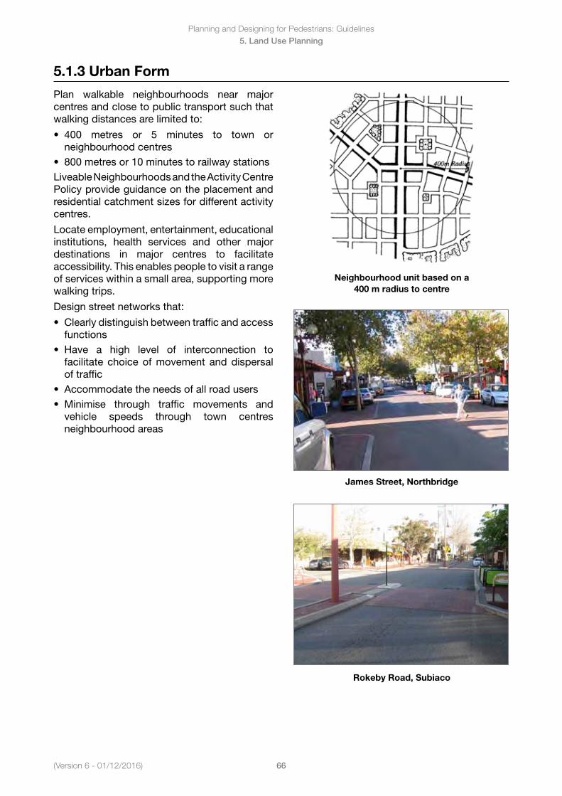
(Version 6 - 01/12/2016)
Planning and Designing for Pedestrians: Guidelines
66
5. Land Use Planning
5.1.3 Urban Form
Plan walkable neighbourhoods near major centres and close to public transport such that walking distances are limited to:
• 400 metres or 5 minutes to town orneighbourhood centres
• 800metresor10minutestorailwaystationsLiveable Neighbourhoods and the Activity Centre Policy provide guidance on the placement and residential catchment sizes for different activity centres.
Locate employment, entertainment, educational institutions, health services and other major destinations in major centres to facilitate accessibility. This enables people to visit a range of services within a small area, supporting more walking trips.
Design street networks that:
• Clearlydistinguishbetweentrafficandaccessfunctions
• Have a high level of interconnection tofacilitate choice of movement and dispersalof traffic
• Accommodatetheneedsofallroadusers• Minimise through traffic movements and
vehicle speeds through town centresneighbourhood areas
Neighbourhood unit based on a 400 m radius to centre
James Street, Northbridge
Rokeby Road, Subiaco
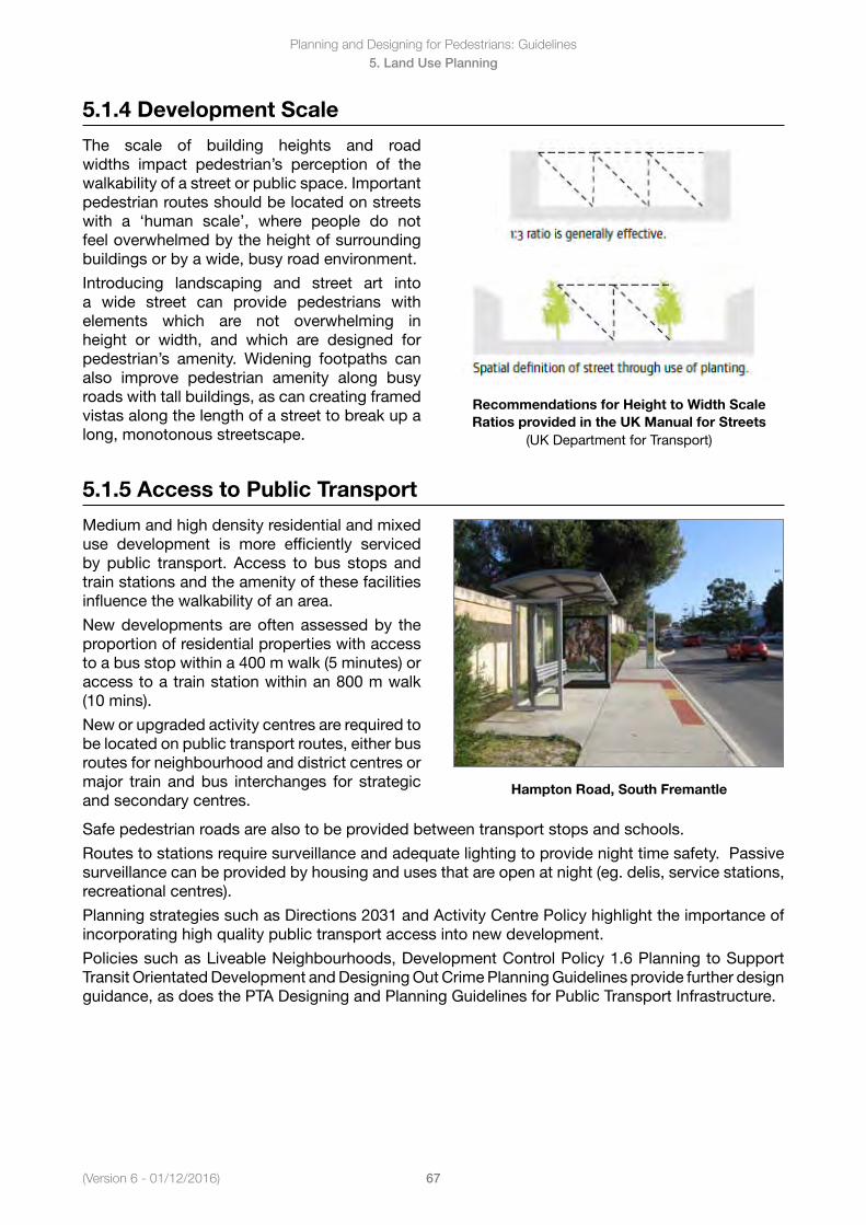
Planning and Designing for Pedestrians: Guidelines
67(Version 6 - 01/12/2016)
5. Land Use Planning
5.1.4 Development Scale
The scale of building heights and road widths impact pedestrian’s perception of the walkability of a street or public space. Important pedestrian routes should be located on streets with a ‘human scale’, where people do not feel overwhelmed by the height of surrounding buildings or by a wide, busy road environment.
Introducing landscaping and street art into a wide street can provide pedestrians with elements which are not overwhelming in height or width, and which are designed for pedestrian’s amenity. Widening footpaths can also improve pedestrian amenity along busy roads with tall buildings, as can creating framed vistas along the length of a street to break up a long, monotonous streetscape.
Recommendations for Height to Width Scale Ratios provided in the UK Manual for Streets
(UK Department for Transport)
5.1.5 Access to Public Transport
Medium and high density residential and mixed use development is more efficiently serviced by public transport. Access to bus stops and train stations and the amenity of these facilities influence the walkability of an area.
New developments are often assessed by the proportion of residential properties with access to a bus stop within a 400 m walk (5 minutes) or access to a train station within an 800 m walk (10 mins).
New or upgraded activity centres are required to be located on public transport routes, either bus routes for neighbourhood and district centres or major train and bus interchanges for strategic and secondary centres.
Hampton Road, South Fremantle
Safe pedestrian roads are also to be provided between transport stops and schools.
Routes to stations require surveillance and adequate lighting to provide night time safety. Passive surveillance can be provided by housing and uses that are open at night (eg. delis, service stations, recreational centres).
Planning strategies such as Directions 2031 and Activity Centre Policy highlight the importance of incorporating high quality public transport access into new development.
Policies such as Liveable Neighbourhoods, Development Control Policy 1.6 Planning to Support Transit Orientated Development and Designing Out Crime Planning Guidelines provide further design guidance, as does the PTA Designing and Planning Guidelines for Public Transport Infrastructure.
Planning and Designing for Pedestrians: Guidelines
68(Version 6 - 01/12/2016)
6. Pedestrian Charateristics
6. Pedestrian Characteristics
6.1 Pedestrian Characteristics
6.1.1 Characteristics
6.1.2 Fit Ambulant
6.1.3 Young Children
6.1.4 Pedestrians with Prams
6.1.5 Seniors
6.1.6 Vision Impairments
6.1.7 HearingImpairments
6.1.8 Cognitive Impairments
6.1.9 Limited Walking Ability
6.1.10 Wheelchair Users
6.1.11 Typical Walking Speeds
6.1.12 Universal Design
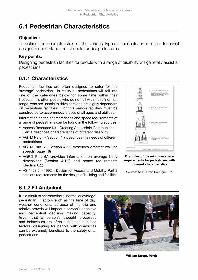
(Version 6 - 01/12/2016)
Planning and Designing for Pedestrians: Guidelines
69
6. Pedestrian Charateristics
6.1 Pedestrian Characteristics
Objective:To outline the characteristics of the various types of pedestrians in order to assist designers understand the rationale for design features.
Key points:Designing pedestrian facilities for people with a range of disability will generally assist all pedestrians.
6.1.1 Characteristics
Pedestrian facilities are often designed to cater for the ‘average’ pedestrian. In reality all pedestrians will fall into one of the categories below for some time within their lifespan. It is often people who do not fall within this ‘normal’ range, who are unable to drive cars and are highly dependent on pedestrian facilities. For this reason facilities must be constructed to accommodate uses of all ages and abilities.
Information on the characteristics and space requirements of a range of pedestrians can be found in the following sources:
• AccessResourceKit-CreatingAccessibleCommunities-Part 1 describes characteristics of different disability
• AGTMPart4–Section4.7describestheneedsofdifferentpedestrians
• AGTMPart6–Section4.5.3describesdifferentwalkingspeeds (page 48)
• AGRD Part 6A provides information on average bodydimensions (Section 4.1.2) and space requirements(Section 6.2)
• AS1428.2–1992–DesignforAccessandMobilityPart2sets out requirements for the design of building and facilities
Examples of the minimum space requirements for pedestrians with
different characteristics
Source: AGRD Part 6A Figure 6.1
6.1.2 Fit Ambulant
It is difficult to characterise a ‘normal or average’ pedestrian. Factors such as the time of day, weather conditions, purpose of the trip and relative crowds will impact a person’s cognitive and perceptual decision making capacity. Given that a person’s thought processes and behaviours are often a reaction to these factors, designing for people with disabilities can be extremely beneficial to the safety of all pedestrians.
William Street, Perth
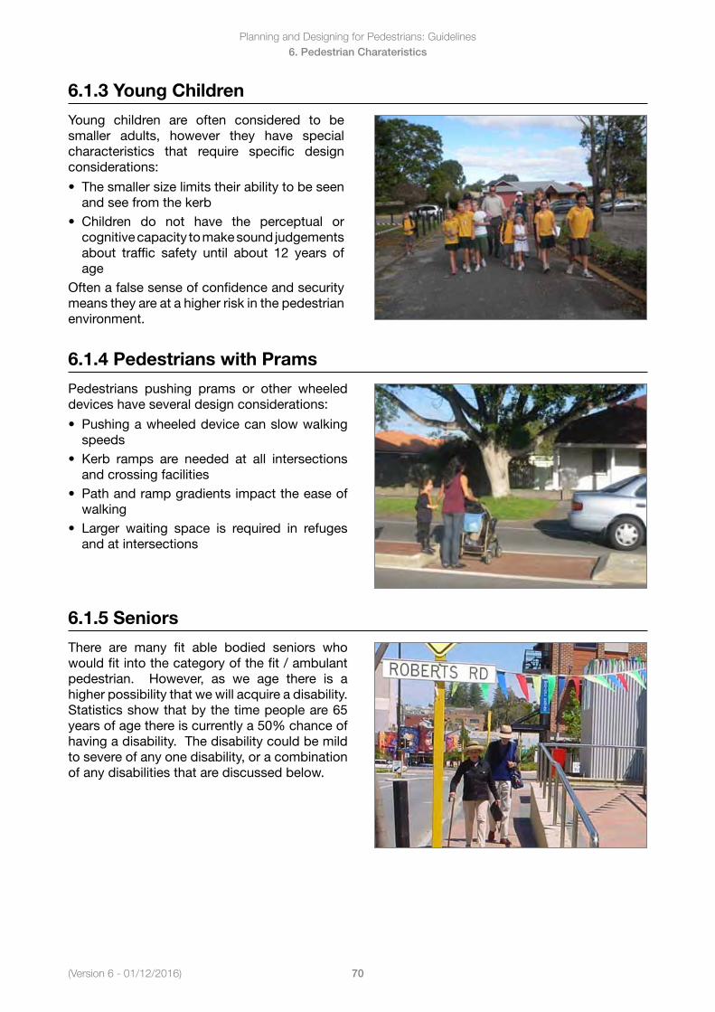
Planning and Designing for Pedestrians: Guidelines
70(Version 6 - 01/12/2016)
6. Pedestrian Charateristics
6.1.3 Young Children
Young children are often considered to be smaller adults, however they have special characteristics that require specific design considerations:
• Thesmallersizelimitstheirabilitytobeseenand see from the kerb
• Children do not have the perceptual orcognitive capacity to make sound judgements about traffic safety until about 12 years ofage
Often a false sense of confidence and security means they are at a higher risk in the pedestrian environment.
6.1.4 Pedestrians with Prams
Pedestrians pushing prams or other wheeled devices have several design considerations:
• Pushingawheeleddevicecanslowwalkingspeeds
• Kerb ramps are needed at all intersectionsand crossing facilities
• Pathandrampgradientsimpacttheeaseofwalking
• Larger waiting space is required in refugesand at intersections
6.1.5 Seniors
There are many fit able bodied seniors who would fit into the category of the fit / ambulant pedestrian. However, as we age there is ahigher possibility that we will acquire a disability. Statistics show that by the time people are 65 years of age there is currently a 50% chance of having a disability. The disability could be mild to severe of any one disability, or a combination of any disabilities that are discussed below.
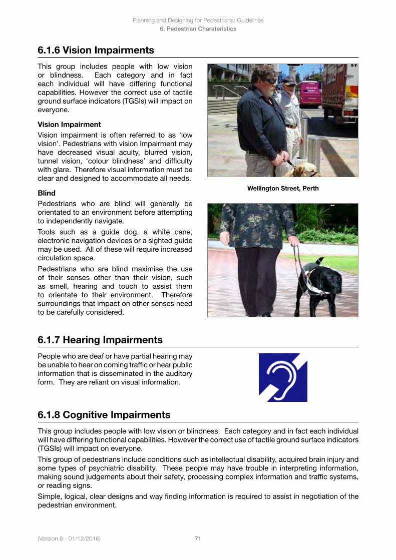
(Version 6 - 01/12/2016)
Planning and Designing for Pedestrians: Guidelines
71
6. Pedestrian Charateristics
6.1.6 Vision Impairments
This group includes people with low vision or blindness. Each category and in fact each individual will have differing functional capabilities.Howeverthecorrectuseoftactileground surface indicators (TGSIs) will impact on everyone.
Vision ImpairmentVision impairment is often referred to as ‘low vision’. Pedestrians with vision impairment may have decreased visual acuity, blurred vision, tunnel vision, ‘colour blindness’ and difficulty with glare. Therefore visual information must be clear and designed to accommodate all needs.
BlindPedestrians who are blind will generally be orientated to an environment before attempting to independently navigate.
Tools such as a guide dog, a white cane, electronic navigation devices or a sighted guide may be used. All of these will require increased circulation space.
Pedestrians who are blind maximise the use of their senses other than their vision, such as smell, hearing and touch to assist them to orientate to their environment. Therefore surroundings that impact on other senses need to be carefully considered.
Wellington Street, Perth
6.1.7 Hearing Impairments
People who are deaf or have partial hearing may be unable to hear on coming traffic or hear public information that is disseminated in the auditory form. They are reliant on visual information.
6.1.8 Cognitive Impairments
This group includes people with low vision or blindness. Each category and in fact each individual willhavedifferingfunctionalcapabilities.Howeverthecorrectuseoftactilegroundsurfaceindicators(TGSIs) will impact on everyone.
This group of pedestrians include conditions such as intellectual disability, acquired brain injury and some types of psychiatric disability. These people may have trouble in interpreting information, making sound judgements about their safety, processing complex information and traffic systems, or reading signs.
Simple, logical, clear designs and way finding information is required to assist in negotiation of the pedestrian environment.
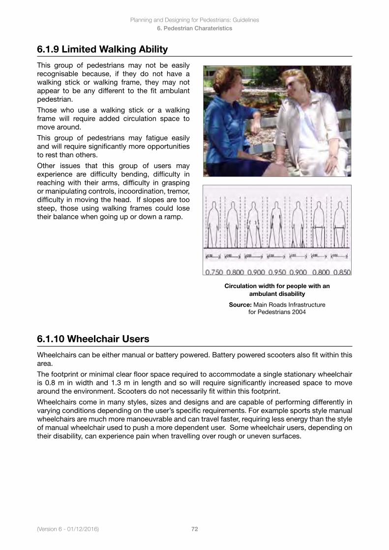
Planning and Designing for Pedestrians: Guidelines
72(Version 6 - 01/12/2016)
6. Pedestrian Charateristics
6.1.9 Limited Walking Ability
This group of pedestrians may not be easily recognisable because, if they do not have a walking stick or walking frame, they may not appear to be any different to the fit ambulant pedestrian.
Those who use a walking stick or a walking frame will require added circulation space to move around.
This group of pedestrians may fatigue easily and will require significantly more opportunities to rest than others.
Other issues that this group of users may experience are difficulty bending, difficulty in reaching with their arms, difficulty in grasping or manipulating controls, incoordination, tremor, difficulty in moving the head. If slopes are too steep, those using walking frames could lose their balance when going up or down a ramp.
Circulation width for people with an ambulant disability
Source: Main Roads Infrastructure for Pedestrians 2004
6.1.10 Wheelchair Users
Wheelchairs can be either manual or battery powered. Battery powered scooters also fit within this area.
The footprint or minimal clear floor space required to accommodate a single stationary wheelchair is 0.8 m in width and 1.3 m in length and so will require significantly increased space to move around the environment. Scooters do not necessarily fit within this footprint.
Wheelchairs come in many styles, sizes and designs and are capable of performing differently in varying conditions depending on the user’s specific requirements. For example sports style manual wheelchairs are much more manoeuvrable and can travel faster, requiring less energy than the style of manual wheelchair used to push a more dependent user. Some wheelchair users, depending on their disability, can experience pain when travelling over rough or uneven surfaces.
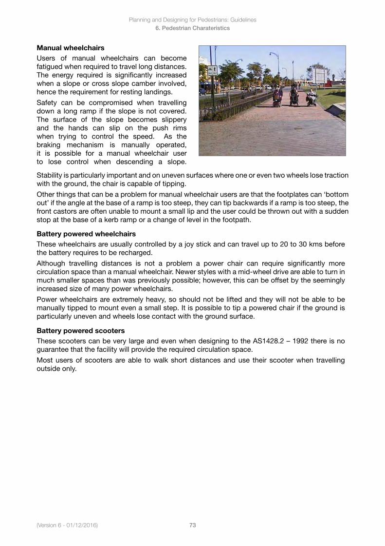
(Version 6 - 01/12/2016)
Planning and Designing for Pedestrians: Guidelines
73
6. Pedestrian Charateristics
Manual wheelchairsUsers of manual wheelchairs can become fatigued when required to travel long distances. The energy required is significantly increased when a slope or cross slope camber involved, hence the requirement for resting landings.
Safety can be compromised when travelling down a long ramp if the slope is not covered. The surface of the slope becomes slippery and the hands can slip on the push rims when trying to control the speed. As the braking mechanism is manually operated, it is possible for a manual wheelchair user to lose control when descending a slope.
Stability is particularly important and on uneven surfaces where one or even two wheels lose traction with the ground, the chair is capable of tipping.
Other things that can be a problem for manual wheelchair users are that the footplates can ‘bottom out’ if the angle at the base of a ramp is too steep, they can tip backwards if a ramp is too steep, the front castors are often unable to mount a small lip and the user could be thrown out with a sudden stop at the base of a kerb ramp or a change of level in the footpath.
Battery powered wheelchairsThese wheelchairs are usually controlled by a joy stick and can travel up to 20 to 30 kms before the battery requires to be recharged.
Although travelling distances is not a problem a power chair can require significantly more circulation space than a manual wheelchair. Newer styles with a mid-wheel drive are able to turn in much smaller spaces than was previously possible; however, this can be offset by the seemingly increased size of many power wheelchairs.
Power wheelchairs are extremely heavy, so should not be lifted and they will not be able to be manually tipped to mount even a small step. It is possible to tip a powered chair if the ground is particularly uneven and wheels lose contact with the ground surface.
Battery powered scootersThesescooterscanbeverylargeandevenwhendesigningtotheAS1428.2–1992thereisnoguarantee that the facility will provide the required circulation space.
Most users of scooters are able to walk short distances and use their scooter when travelling outside only.
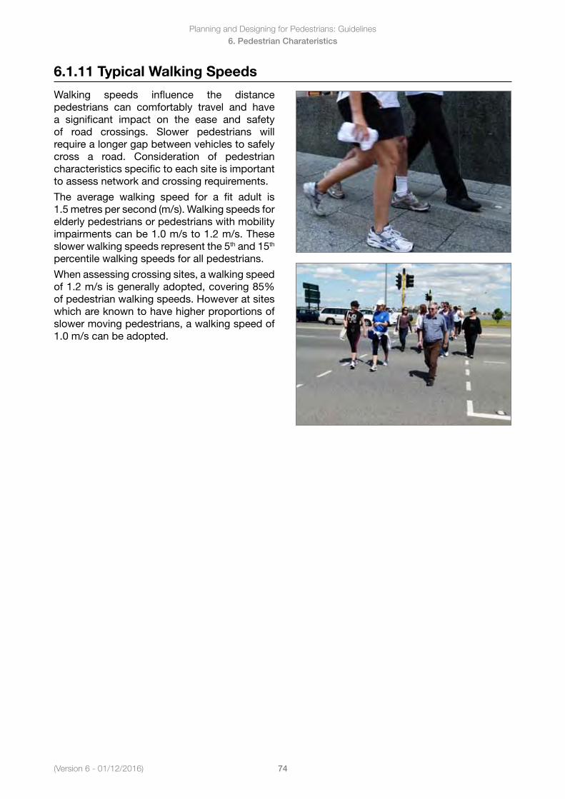
Planning and Designing for Pedestrians: Guidelines
74(Version 6 - 01/12/2016)
6. Pedestrian Charateristics
6.1.11 Typical Walking Speeds
Walking speeds influence the distance pedestrians can comfortably travel and have a significant impact on the ease and safety of road crossings. Slower pedestrians will require a longer gap between vehicles to safely cross a road. Consideration of pedestrian characteristics specific to each site is important to assess network and crossing requirements.
The average walking speed for a fit adult is 1.5 metres per second (m/s). Walking speeds for elderly pedestrians or pedestrians with mobility impairments can be 1.0 m/s to 1.2 m/s. These slower walking speeds represent the 5th and 15th percentile walking speeds for all pedestrians.
When assessing crossing sites, a walking speed of 1.2 m/s is generally adopted, covering 85% ofpedestrianwalkingspeeds.Howeveratsiteswhich are known to have higher proportions of slower moving pedestrians, a walking speed of 1.0 m/s can be adopted.
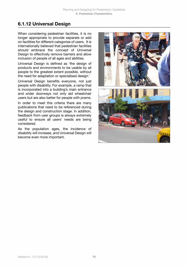
(Version 6 - 01/12/2016)
Planning and Designing for Pedestrians: Guidelines
75
6. Pedestrian Charateristics
6.1.12 Universal Design
When considering pedestrian facilities, it is no longer appropriate to provide separate or add on facilities for different categories of users. It is internationally believed that pedestrian facilities should embrace the concept of Universal Design to effectively remove barriers and allow inclusion of people of all ages and abilities.
Universal Design is defined as ‘the design of products and environments to be usable by all people to the greatest extent possible, without the need for adaptation or specialised design.’
Universal Design benefits everyone, not just people with disability. For example, a ramp that is incorporated into a building’s main entrance and wider doorways not only aid wheelchair users but are also better for people with prams.
In order to meet this criteria there are many publications that need to be referenced during the design and construction stage. In addition, feedback from user groups is always extremely useful to ensure all users’ needs are being considered.
As the population ages, the incidence of disability will increase, and Universal Design will become even more important.
Planning and Designing for Pedestrians: Guidelines
76(Version 6 - 01/12/2016)
7. Pedestrian Paths
7. Pedestrian PathsIn this Section7.1 Path Widths
7.1.1 Path Audit Tools7.1.2 Types of Path Facilities7.1.3 Location of Paths7.1.4 Path location - Factors for consideration7.1.5 Zones Associated with Footpaths
7.2 Street Furniture7.2.1 Placement of Street Furniture 7.2.2 Colour7.2.3 Seating7.2.4 Bins7.2.5 Drinking Fountains7.2.6 Telephones7.2.7 Street Trees and Vegetation7.2.8 Bus Stop Shelter and Signs
7.3 Grates / Covers7.3.1 Grates
7.4 Vertical Clearances
7.5 Surfaces7.5.1 Paved Path Surfaces7.5.2 Crossfall and Camber7.5.3 Drainage
7.6 Gradients and Ramps7.6.1 Footpath Definition7.6.2 Ramp Definition7.6.3 Length of Ramps7.6.4 Width7.6.5 Ramp and Footpath Landings7.6.6 Landing Dimensions7.6.7 HandrailPositionsonRamps7.6.8 HandrailDetails7.6.9 Edge Treatments7.6.10 Warning Tactile Ground Surface Indicators (TGSI)
7.7 Steps and Stairs7.7.1 Geometry7.7.2 Nosing7.7.3 HandrailDetails
7.8 Crossovers / Driveways7.8.1 Warning TGSI
7.9 Barricades (including chicanes and bollards)7.9.1 Chicanes and Mazes7.9.2 Temporary Barricades
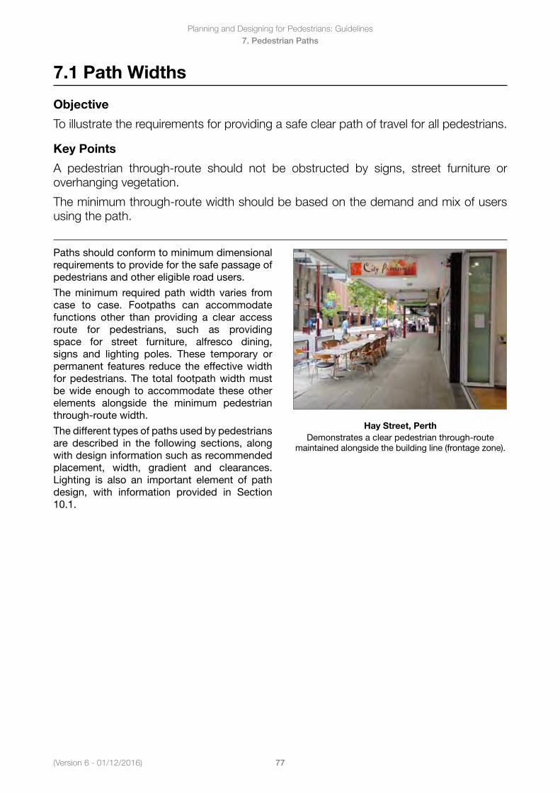
(Version 6 - 01/12/2016)
Planning and Designing for Pedestrians: Guidelines
77
7. Pedestrian Paths
7.1 Path Widths
Objective
To illustrate the requirements for providing a safe clear path of travel for all pedestrians.
Key Points
A pedestrian through-route should not be obstructed by signs, street furniture or overhanging vegetation.
The minimum through-route width should be based on the demand and mix of users using the path.
Paths should conform to minimum dimensional requirements to provide for the safe passage of pedestrians and other eligible road users.
The minimum required path width varies from case to case. Footpaths can accommodate functions other than providing a clear access route for pedestrians, such as providing space for street furniture, alfresco dining, signs and lighting poles. These temporary or permanent features reduce the effective width for pedestrians. The total footpath width must be wide enough to accommodate these other elements alongside the minimum pedestrian through-route width.
The different types of paths used by pedestrians are described in the following sections, along with design information such as recommended placement, width, gradient and clearances. Lighting is also an important element of path design, with information provided in Section 10.1.
Hay Street, PerthDemonstrates a clear pedestrian through-route
maintained alongside the building line (frontage zone).
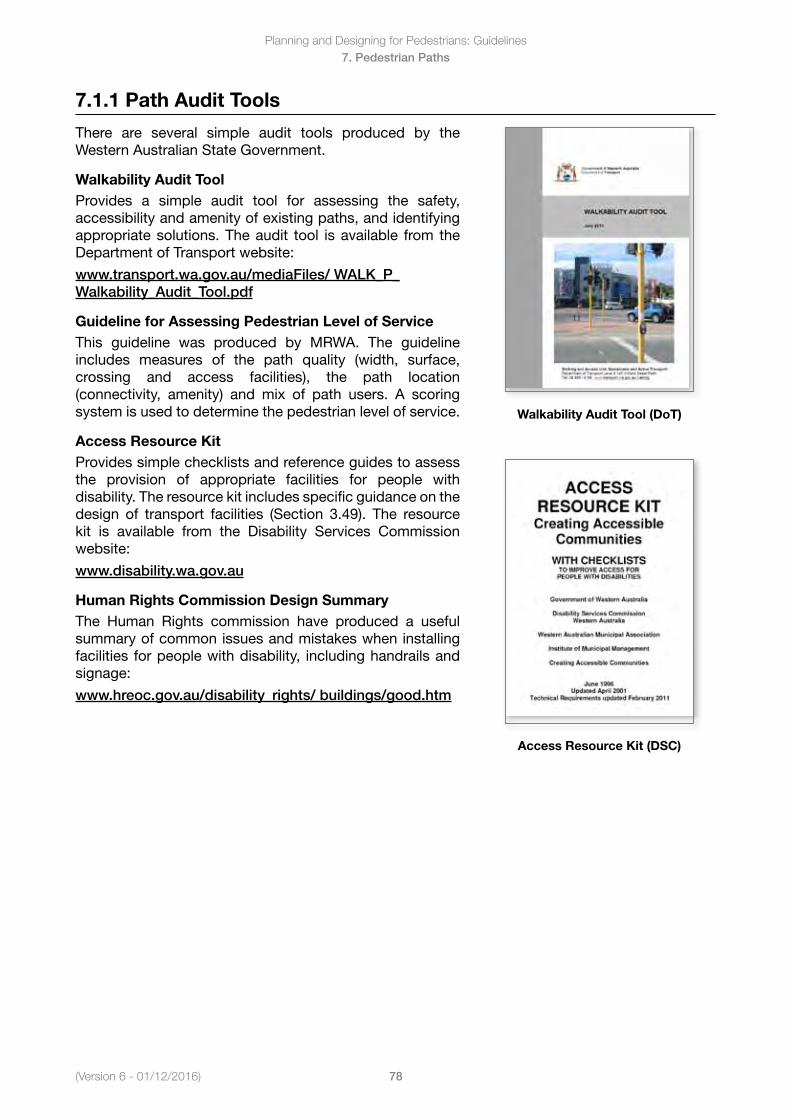
Planning and Designing for Pedestrians: Guidelines
78(Version 6 - 01/12/2016)
7. Pedestrian Paths
7.1.1 Path Audit Tools
There are several simple audit tools produced by the Western Australian State Government.
Walkability Audit ToolProvides a simple audit tool for assessing the safety, accessibility and amenity of existing paths, and identifying appropriate solutions. The audit tool is available from the Department of Transport website:
www.transport.wa.gov.au/mediaFiles/ WALK_P_Walkability_Audit_Tool.pdf
Guideline for Assessing Pedestrian Level of Service This guideline was produced by MRWA. The guideline includes measures of the path quality (width, surface, crossing and access facilities), the path location (connectivity, amenity) and mix of path users. A scoring system is used to determine the pedestrian level of service.
Access Resource KitProvides simple checklists and reference guides to assess the provision of appropriate facilities for people with disability. The resource kit includes specific guidance on the design of transport facilities (Section 3.49). The resource kit is available from the Disability Services Commission website:
www.disability.wa.gov.au
Human Rights Commission Design SummaryThe Human Rights commission have produced a usefulsummary of common issues and mistakes when installing facilities for people with disability, including handrails and signage:
www.hreoc.gov.au/disability_rights/ buildings/good.htm
Walkability Audit Tool (DoT)
Access Resource Kit (DSC)
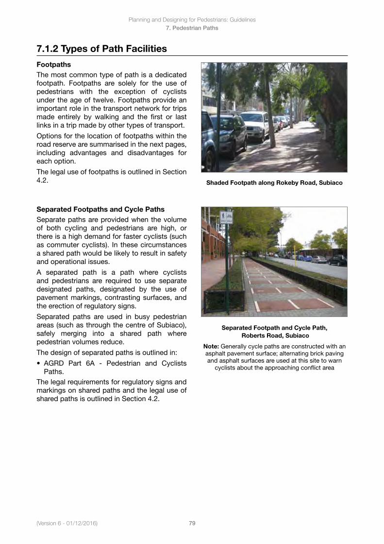
(Version 6 - 01/12/2016)
Planning and Designing for Pedestrians: Guidelines
79
7. Pedestrian Paths
7.1.2 Types of Path Facilities
FootpathsThe most common type of path is a dedicated footpath. Footpaths are solely for the use of pedestrians with the exception of cyclists under the age of twelve. Footpaths provide an important role in the transport network for trips made entirely by walking and the first or last links in a trip made by other types of transport.
Options for the location of footpaths within the road reserve are summarised in the next pages, including advantages and disadvantages for each option.
The legal use of footpaths is outlined in Section 4.2. Shaded Footpath along Rokeby Road, Subiaco
Separated Footpaths and Cycle PathsSeparate paths are provided when the volume of both cycling and pedestrians are high, or there is a high demand for faster cyclists (such as commuter cyclists). In these circumstances a shared path would be likely to result in safety and operational issues.
A separated path is a path where cyclists and pedestrians are required to use separate designated paths, designated by the use of pavement markings, contrasting surfaces, and the erection of regulatory signs.
Separated paths are used in busy pedestrian areas (such as through the centre of Subiaco), safely merging into a shared path where pedestrian volumes reduce.
The design of separated paths is outlined in:
• AGRD Part 6A - Pedestrian and CyclistsPaths.
The legal requirements for regulatory signs and markings on shared paths and the legal use of shared paths is outlined in Section 4.2.
Separated Footpath and Cycle Path, Roberts Road, Subiaco
Note: Generally cycle paths are constructed with an asphalt pavement surface; alternating brick paving and asphalt surfaces are used at this site to warn
cyclists about the approaching conflict area
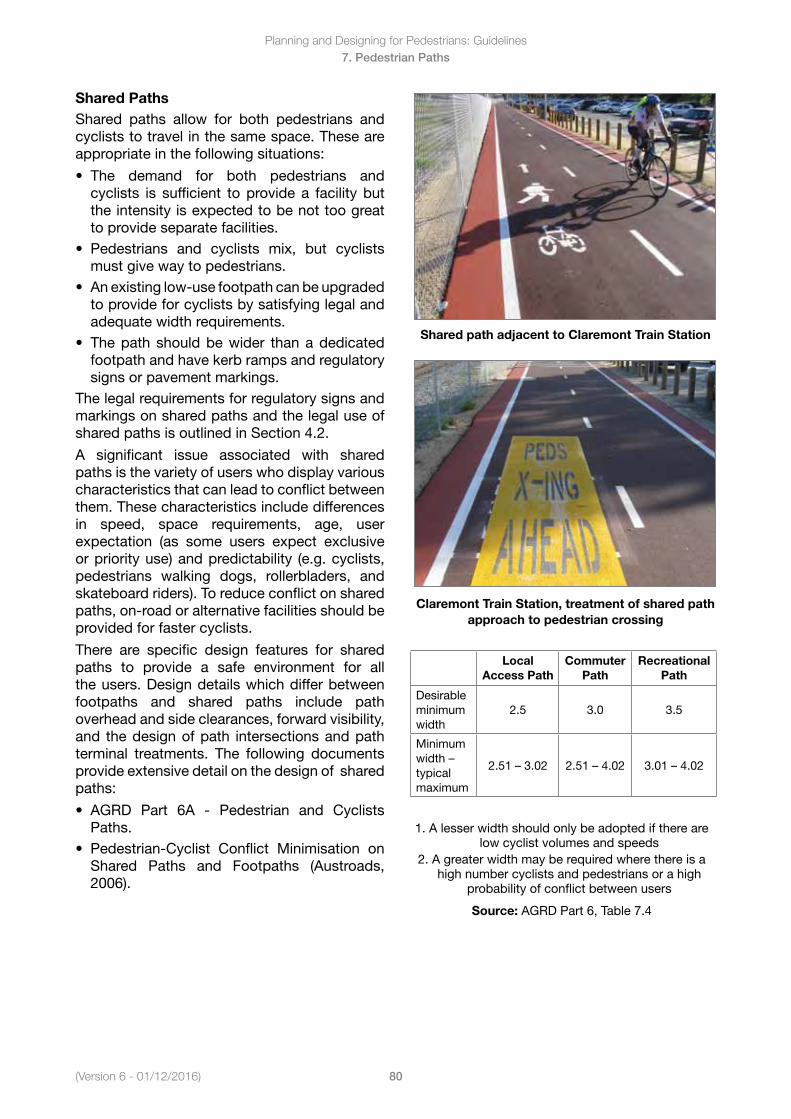
Planning and Designing for Pedestrians: Guidelines
80(Version 6 - 01/12/2016)
7. Pedestrian Paths
Shared PathsShared paths allow for both pedestrians and cyclists to travel in the same space. These are appropriate in the following situations:
• The demand for both pedestrians andcyclists is sufficient to provide a facility butthe intensity is expected to be not too greatto provide separate facilities.
• Pedestrians and cyclists mix, but cyclistsmust give way to pedestrians.
• Anexistinglow-usefootpathcanbeupgradedto provide for cyclists by satisfying legal andadequate width requirements.
• Thepath shouldbewider thanadedicatedfootpath and have kerb ramps and regulatorysigns or pavement markings.
The legal requirements for regulatory signs and markings on shared paths and the legal use of shared paths is outlined in Section 4.2.
A significant issue associated with shared paths is the variety of users who display various characteristics that can lead to conflict between them. These characteristics include differences in speed, space requirements, age, user expectation (as some users expect exclusive or priority use) and predictability (e.g. cyclists, pedestrians walking dogs, rollerbladers, and skateboard riders). To reduce conflict on shared paths, on-road or alternative facilities should be provided for faster cyclists.
There are specific design features for shared paths to provide a safe environment for all the users. Design details which differ between footpaths and shared paths include path overhead and side clearances, forward visibility, and the design of path intersections and path terminal treatments. The following documents provide extensive detail on the design of shared paths:
• AGRD Part 6A - Pedestrian and CyclistsPaths.
• Pedestrian-Cyclist Conflict Minimisation onShared Paths and Footpaths (Austroads,2006).
Shared path adjacent to Claremont Train Station
Claremont Train Station, treatment of shared path approach to pedestrian crossing
Local Access Path
Commuter Path
Recreational Path
Desirable minimum width
2.5 3.0 3.5
Minimum width–typical maximum
2.51–3.02 2.51–4.02 3.01–4.02
1. A lesser width should only be adopted if there arelow cyclist volumes and speeds
2. A greater width may be required where there is ahigh number cyclists and pedestrians or a high
probability of conflict between users
Source: AGRD Part 6, Table 7.4
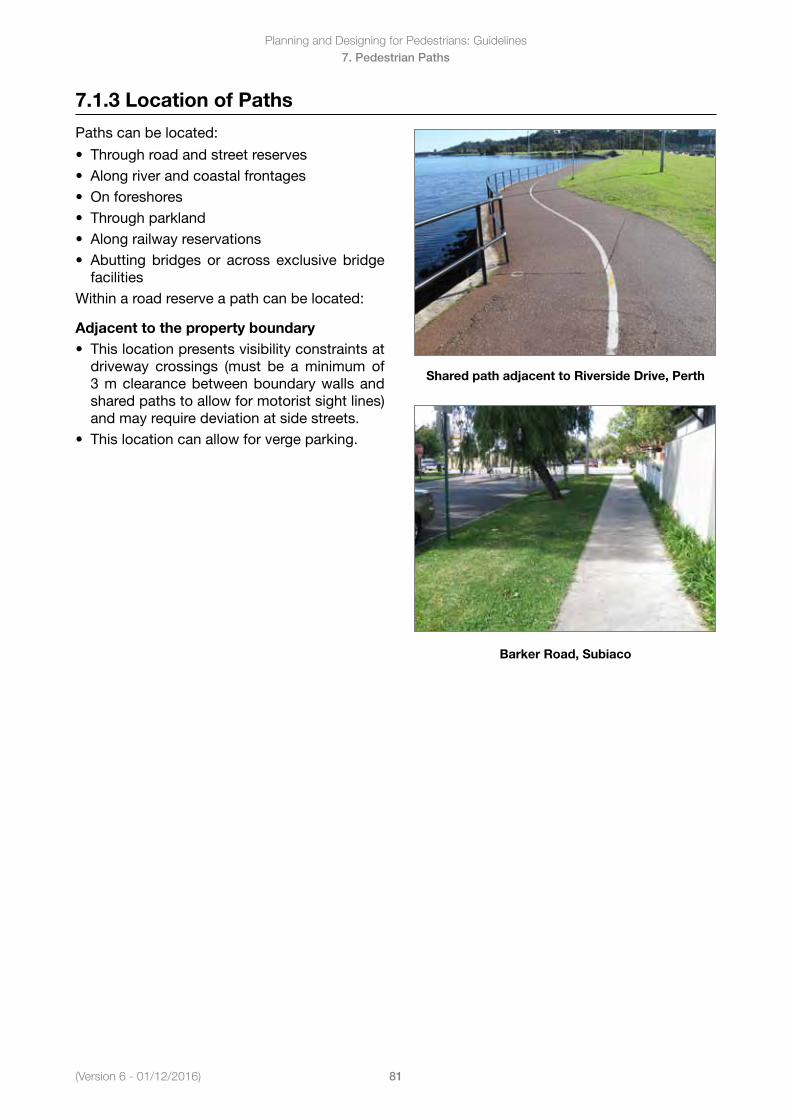
(Version 6 - 01/12/2016)
Planning and Designing for Pedestrians: Guidelines
81
7. Pedestrian Paths
7.1.3 Location of Paths
Paths can be located:
• Throughroadandstreetreserves• Alongriverandcoastalfrontages• Onforeshores• Throughparkland• Alongrailwayreservations• Abuttingbridges or across exclusive bridge
facilitiesWithin a road reserve a path can be located:
Adjacent to the property boundary• Thislocationpresentsvisibilityconstraintsat
driveway crossings (must be a minimum of3 m clearance between boundary walls andshared paths to allow for motorist sight lines)and may require deviation at side streets.
• Thislocationcanallowforvergeparking.
Shared path adjacent to Riverside Drive, Perth
Barker Road, Subiaco
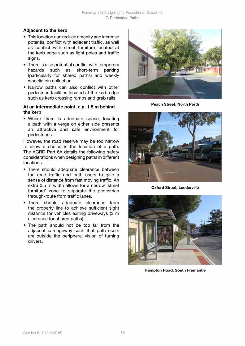
Planning and Designing for Pedestrians: Guidelines
82(Version 6 - 01/12/2016)
7. Pedestrian Paths
Adjacent to the kerb• Thislocationcanreduceamenityandincrease
potential conflict with adjacent traffic, as wellas conflict with street furniture located atthe kerb edge such as light poles and trafficsigns.
• Thereisalsopotentialconflictwithtemporaryhazards such as short-term parking(particularly for shared paths) and weeklywheelie bin collection.
• Narrow paths can also conflict with otherpedestrian facilities located at the kerb edgesuch as kerb crossing ramps and grab rails.
At an intermediate point, e.g. 1.5 m behind the kerb• Where there is adequate space, locating
a path with a verge on either side presentsan attractive and safe environment forpedestrians.
However, the road reservemaybe toonarrowto allow a choice in the location of a path. The AGRD Part 6A details the following safety considerations when designing paths in different locations:
• There should adequate clearance betweenthe road traffic and path users to give asense of distance from fast moving traffic. Anextra 0.5 m width allows for a narrow ‘streetfurniture’ zone to separate the pedestrianthrough-route from traffic lanes.
• There should adequate clearance fromthe property line to achieve sufficient sightdistance for vehicles exiting driveways (3 mclearance for shared paths).
• The path should not be too far from theadjacent carriageway such that path usersare outside the peripheral vision of turningdrivers.
Peach Street, North Perth
Oxford Street, Leederville
Hampton Road, South Fremantle
(Version 6 - 01/12/2016)
Planning and Designing for Pedestrians: Guidelines
83
7. Pedestrian Paths
7.1.4 Path location - Factors for consideration
Close to kerb • Inmanycasesistheonlyoptionbecauseoftheroadreservewidthavailable.• Offers thebest visibility of path users to drivers reversing out of their properties, particularly
where high screen walls exist at the boundaries.• Willbeusedintwodirectionsandallowscycliststorunoffthepathandrideagainsttheflowof
motor traffic on the road pavement. Overseas experience has shown wrong-way movements tobe a major problem (Cross and Fisher 1977).
• Mayresultinparkedcarsbeingahazardtocyclistsduetotheopeningofvehicledoorsintothepath.
• Mayresultinpersonsenteringandexitingparkedcarsbeingputatriskduetotheproximityofbicycle movements to the cars.
• Followsthelongitudinalprofileofthekerbandisthereforegenerallycheapertoconstructbecauseof reduced earthworks.
• Maybepreferredbyabuttinglandownersintermsofprivacyandnaturestripdisruption.• May result in theeffectivepathwidthbeing reducedbykerb returns (however, theuseofAS
1428.1 style side ramps (see Figure 8 in AS 1428.1) would be of some assistance at driveways orthe path profile being adversely affected at the cross over.
• Ifwide,maybeviewedasdetractingfromtheappearanceofthestreetscapeandmayimplyahigher speed environment.
• Islesspleasantforcyclistsbecauseoftrafficnoise,fumesandspeed,andperhapsthesplashingof water from gutters.
• Mayberelativelyunaffectedbythepresenceoffencesvaryinginheightandtype,orhavingsharpor exposed edges or protrusions.
Near property boundary• Providesamorepleasantcyclingenvironmentandisperceivedtobesaferforinexperiencedor
young cyclists.• Maylimitvisibilityofpathuserstodriversreversingoutofdriveways,ortodriversturningleftfrom
the abutting carriageway, where path users are beyond the driver’s peripheral vision.• Doesnotnecessarilyfollowthekerbprofileandmayresultinsteepergradientsforcyclistsorbe
more costly to construct.• Maybeviewedashavingalowernegativevisualimpactonthestreetthanakerbsidepath.• Maybeunacceptabletoabuttinglandowners.• Ismoreefficientforthemailservice,ifthenaturestripisverywide.• Shouldpreferablybedeviatedtoalocationatleastonecarlengthbackfromroadintersections,
adjacent to which the path crosses, to facilitate passage behind a queued car).• Allowsspaceforgarbage(e.g.wheelie)binstobeaccommodatedclearofpathandforpitlids
for utilities to be located outside of the path surface. Pit lids should not be located within pathsas they can create an uncomfortable ride and constitute a trip hazard for pedestrians.
Factors considered in the choice of path alignment in road reservationsSource: AGRD Part 6A, Table 5.1
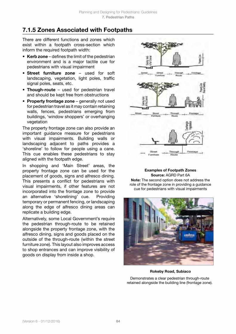
Planning and Designing for Pedestrians: Guidelines
84(Version 6 - 01/12/2016)
7. Pedestrian Paths
7.1.5 Zones Associated with Footpaths
There are different functions and zones which exist within a footpath cross-section which inform the required footpath width:
• Kerb zone–definesthelimitofthepedestrianenvironment and is a major tactile cue forpedestrians with visual impairment
• Street furniture zone – used for softlandscaping, vegetation, light poles, trafficsignal poles, seats, etc.
• Though-route – used for pedestrian traveland should be kept free from obstructions
• Property frontage zone–generallynotusedfor pedestrian travel as it may contain retaining walls, fences, pedestrians emerging frombuildings, ‘window shoppers’ or overhangingvegetation
The property frontage zone can also provide an important guidance measure for pedestrians with visual impairments. Building walls or landscaping adjacent to paths provides a ‘shoreline’ to follow for people using a cane. This cue enables these pedestrians to stay aligned with the footpath edge.
In shopping and ‘Main Street’ areas, the property frontage zone can be used for the placement of goods, signs and alfresco dining. This presents a conflict for pedestrians with visual impairments, if other features are not incorporated into the frontage zone to provide an alternative ‘shorelining’ cue. Providing temporary or permanent fencing, or landscaping along the edge of alfresco dining areas can replicate a building edge.
Alternatively, some Local Government’s require the pedestrian through-route to be retained alongside the property frontage zone, with the alfresco dining, signs and goods placed on the outside of the through-route (within the street furniture zone). This layout also improves access to shop entrances and can improve visibility of goods on display from inside a shop.
Examples of Footpath Zones Source: AGRD Part 6A
Note: The second option does not address the role of the frontage zone in providing a guidance
cue for pedestrians with visual impairments
Rokeby Road, Subiaco
Demonstrates a clear pedestrian through-route retained alongside the building line (frontage zone).
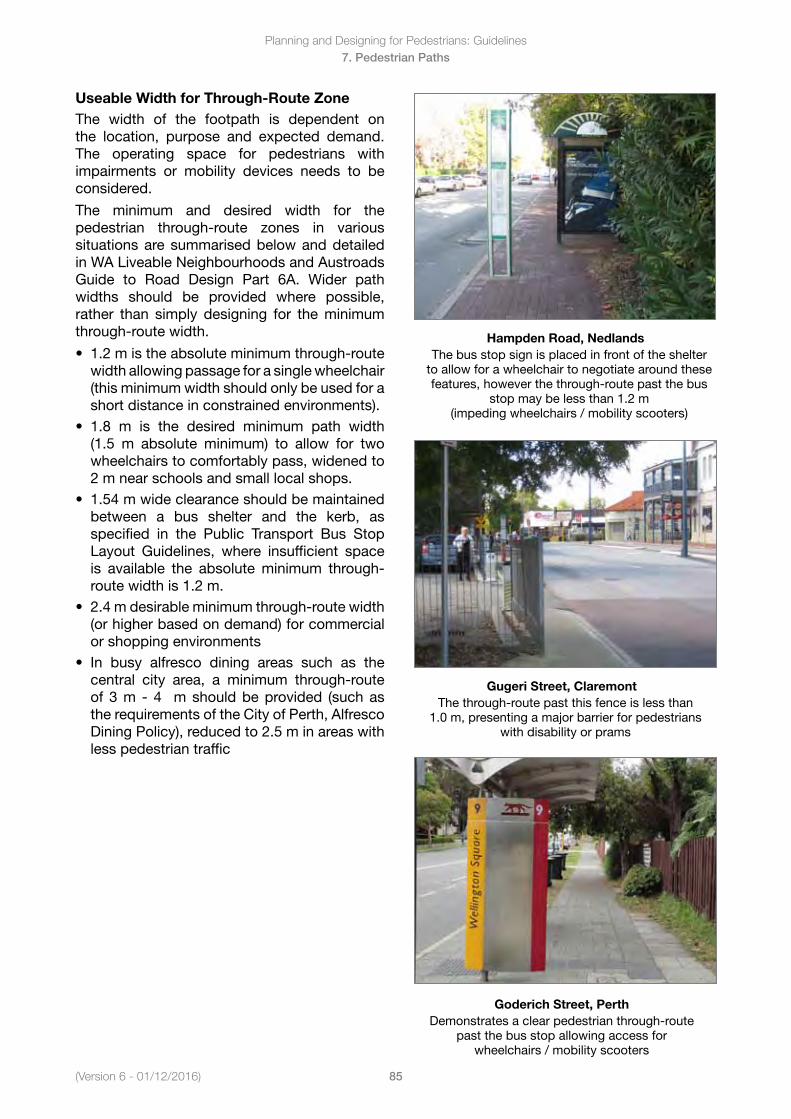
(Version 6 - 01/12/2016)
Planning and Designing for Pedestrians: Guidelines
85
7. Pedestrian Paths
Useable Width for Through-Route ZoneThe width of the footpath is dependent on the location, purpose and expected demand. The operating space for pedestrians with impairments or mobility devices needs to be considered.
The minimum and desired width for the pedestrian through-route zones in various situations are summarised below and detailed in WA Liveable Neighbourhoods and Austroads Guide to Road Design Part 6A. Wider path widths should be provided where possible, rather than simply designing for the minimum through-route width.
• 1.2mistheabsoluteminimumthrough-routewidth allowing passage for a single wheelchair (this minimum width should only be used for ashort distance in constrained environments).
• 1.8 m is the desired minimum path width(1.5 m absolute minimum) to allow for twowheelchairs to comfortably pass, widened to2 m near schools and small local shops.
• 1.54mwideclearanceshouldbemaintainedbetween a bus shelter and the kerb, asspecified in the Public Transport Bus StopLayout Guidelines, where insufficient spaceis available the absolute minimum through-route width is 1.2 m.
• 2.4mdesirableminimumthrough-routewidth(or higher based on demand) for commercialor shopping environments
• In busy alfresco dining areas such as thecentral city area, a minimum through-routeof 3 m - 4 m should be provided (such asthe requirements of the City of Perth, AlfrescoDining Policy), reduced to 2.5 m in areas withless pedestrian traffic
Hampden Road, NedlandsThe bus stop sign is placed in front of the shelter
to allow for a wheelchair to negotiate around these features, however the through-route past the bus
stop may be less than 1.2 m (impeding wheelchairs / mobility scooters)
Gugeri Street, ClaremontThe through-route past this fence is less than
1.0 m, presenting a major barrier for pedestrians with disability or prams
Goderich Street, PerthDemonstrates a clear pedestrian through-route
past the bus stop allowing access for wheelchairs / mobility scooters
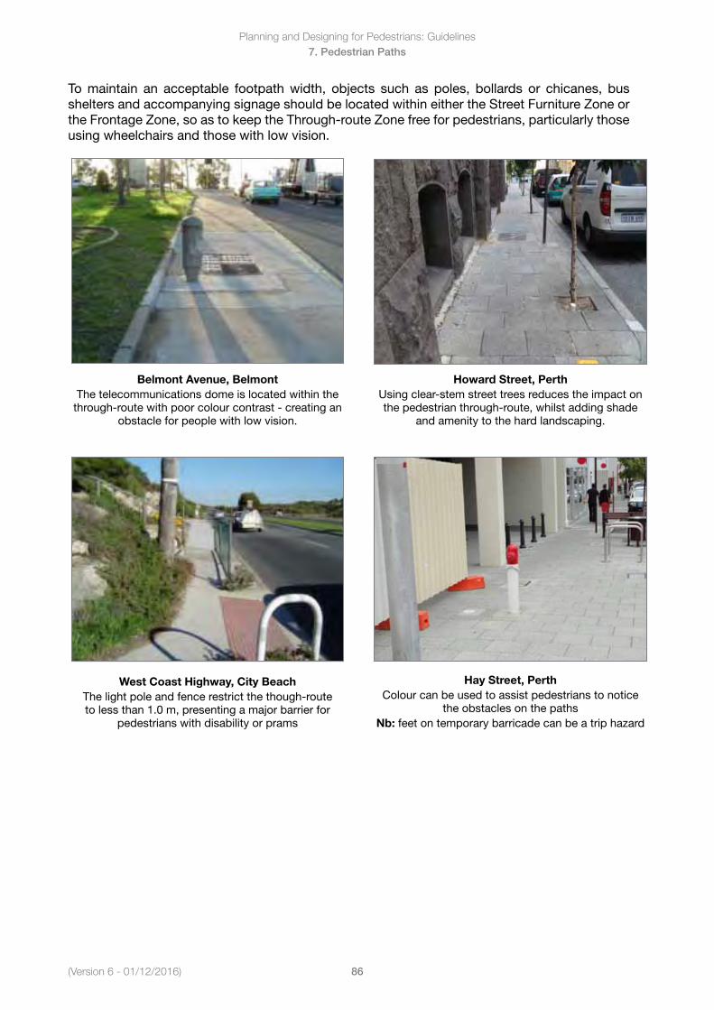
Planning and Designing for Pedestrians: Guidelines
86(Version 6 - 01/12/2016)
7. Pedestrian Paths
To maintain an acceptable footpath width, objects such as poles, bollards or chicanes, bus shelters and accompanying signage should be located within either the Street Furniture Zone or the Frontage Zone, so as to keep the Through-route Zone free for pedestrians, particularly those using wheelchairs and those with low vision.
Belmont Avenue, BelmontThe telecommunications dome is located within the
through-route with poor colour contrast - creating an obstacle for people with low vision.
West Coast Highway, City BeachThe light pole and fence restrict the though-route to less than 1.0 m, presenting a major barrier for
pedestrians with disability or prams
Howard Street, PerthUsing clear-stem street trees reduces the impact on the pedestrian through-route, whilst adding shade
and amenity to the hard landscaping.
Hay Street, PerthColour can be used to assist pedestrians to notice
the obstacles on the pathsNb: feet on temporary barricade can be a trip hazard
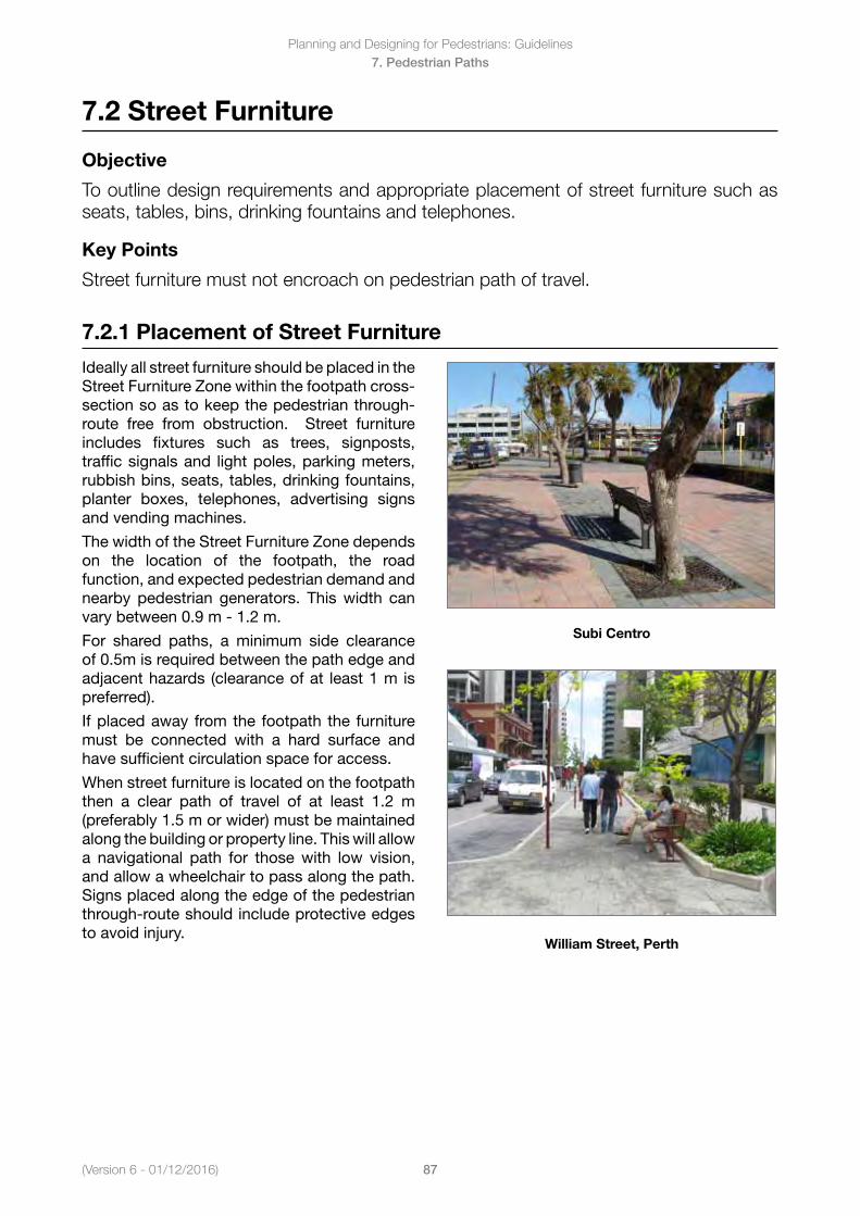
(Version 6 - 01/12/2016)
Planning and Designing for Pedestrians: Guidelines
87
7. Pedestrian Paths
7.2 Street Furniture
Objective
To outline design requirements and appropriate placement of street furniture such as seats, tables, bins, drinking fountains and telephones.
Key Points
Street furniture must not encroach on pedestrian path of travel.
7.2.1 Placement of Street Furniture
Ideally all street furniture should be placed in the Street Furniture Zone within the footpath cross-section so as to keep the pedestrian through-route free from obstruction. Street furniture includes fixtures such as trees, signposts, traffic signals and light poles, parking meters, rubbish bins, seats, tables, drinking fountains, planter boxes, telephones, advertising signs and vending machines.
The width of the Street Furniture Zone depends on the location of the footpath, the road function, and expected pedestrian demand and nearby pedestrian generators. This width can vary between 0.9 m - 1.2 m.
For shared paths, a minimum side clearance of 0.5m is required between the path edge and adjacent hazards (clearance of at least 1 m is preferred).
If placed away from the footpath the furniture must be connected with a hard surface and have sufficient circulation space for access.
When street furniture is located on the footpath then a clear path of travel of at least 1.2 m (preferably 1.5 m or wider) must be maintained along the building or property line. This will allow a navigational path for those with low vision, and allow a wheelchair to pass along the path. Signs placed along the edge of the pedestrian through-route should include protective edges to avoid injury.
Subi Centro
William Street, Perth
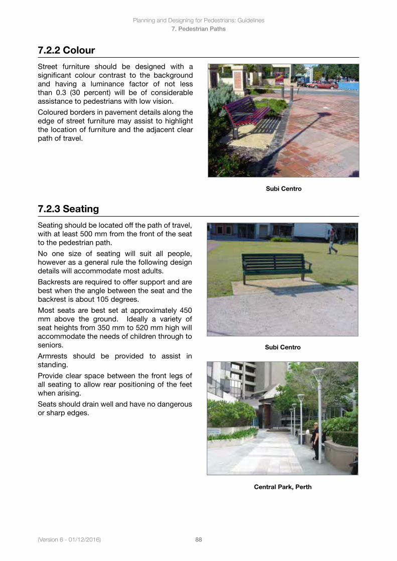
Planning and Designing for Pedestrians: Guidelines
88(Version 6 - 01/12/2016)
7. Pedestrian Paths
7.2.2 Colour
Street furniture should be designed with a significant colour contrast to the background and having a luminance factor of not less than 0.3 (30 percent) will be of considerable assistance to pedestrians with low vision.
Coloured borders in pavement details along the edge of street furniture may assist to highlight the location of furniture and the adjacent clear path of travel.
Subi Centro
7.2.3 Seating
Seating should be located off the path of travel, with at least 500 mm from the front of the seat to the pedestrian path.
No one size of seating will suit all people, however as a general rule the following design details will accommodate most adults.
Backrests are required to offer support and are best when the angle between the seat and the backrest is about 105 degrees.
Most seats are best set at approximately 450 mm above the ground. Ideally a variety of seat heights from 350 mm to 520 mm high will accommodate the needs of children through to seniors.
Armrests should be provided to assist in standing.
Provide clear space between the front legs of all seating to allow rear positioning of the feet when arising.
Seats should drain well and have no dangerous or sharp edges.
Subi Centro
Central Park, Perth
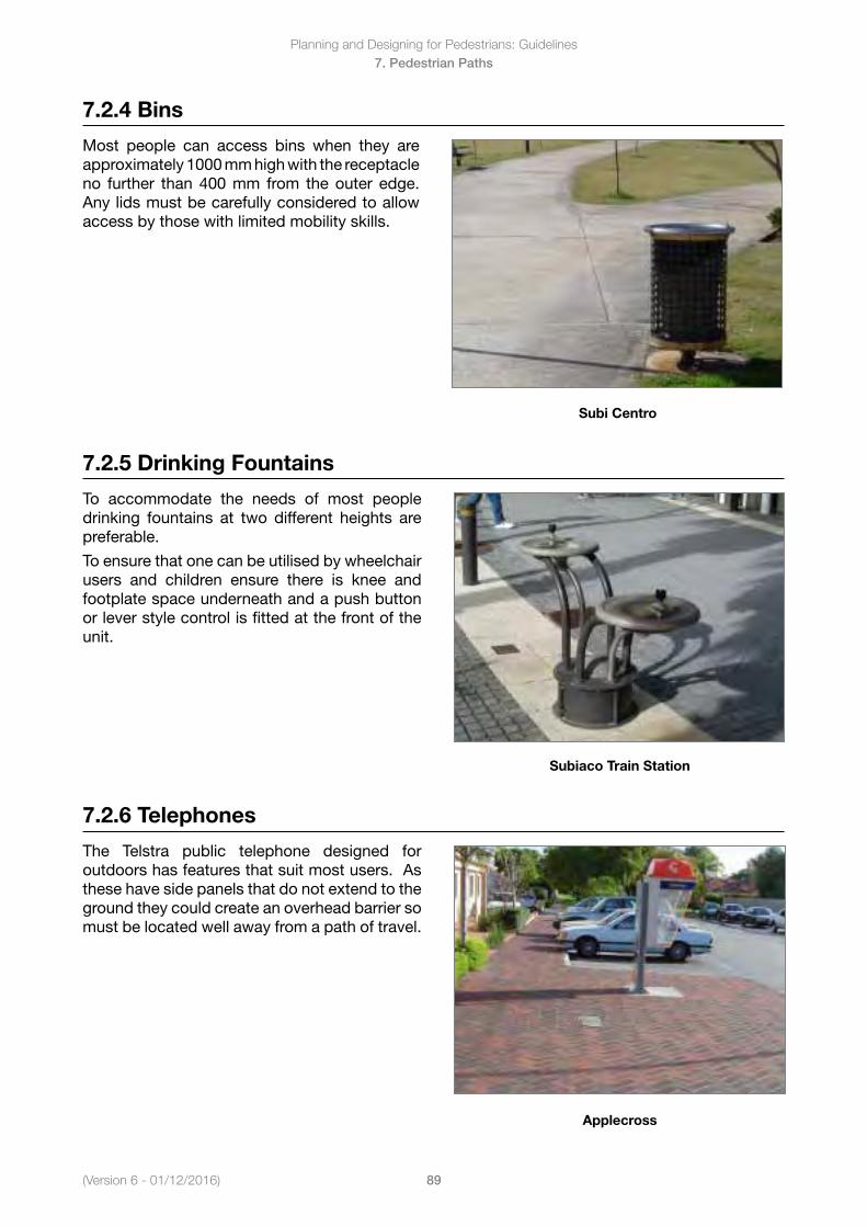
(Version 6 - 01/12/2016)
Planning and Designing for Pedestrians: Guidelines
89
7. Pedestrian Paths
7.2.4 Bins
Most people can access bins when they are approximately 1000 mm high with the receptacle no further than 400 mm from the outer edge. Any lids must be carefully considered to allow access by those with limited mobility skills.
Subi Centro
7.2.5 Drinking Fountains
To accommodate the needs of most people drinking fountains at two different heights are preferable.
To ensure that one can be utilised by wheelchair users and children ensure there is knee and footplate space underneath and a push button or lever style control is fitted at the front of the unit.
Subiaco Train Station
7.2.6 Telephones
The Telstra public telephone designed for outdoors has features that suit most users. As these have side panels that do not extend to the ground they could create an overhead barrier so must be located well away from a path of travel.
Applecross
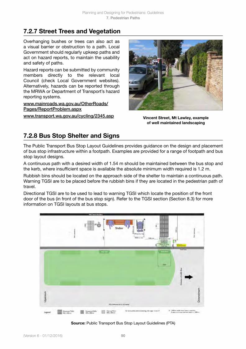
Planning and Designing for Pedestrians: Guidelines
90(Version 6 - 01/12/2016)
7. Pedestrian Paths
7.2.7 Street Trees and Vegetation
Overhanging bushes or trees can also act as a visual barrier or obstruction to a path. Local Government should regularly upkeep paths and act on hazard reports, to maintain the usability and safety of paths.
Hazardreportscanbesubmittedbycommunitymembers directly to the relevant local Council (check Local Government websites). Alternatively, hazards can be reported through the MRWA or Department of Transport’s hazard reporting systems.
www.mainroads.wa.gov.au/OtherRoads/Pages/ReportProblem.aspx
www.transport.wa.gov.au/cycling/2345.asp Vincent Street, Mt Lawley, example of well maintained landscaping
7.2.8 Bus Stop Shelter and Signs
The Public Transport Bus Stop Layout Guidelines provides guidance on the design and placement of bus stop infrastructure within a footpath. Examples are provided for a range of footpath and bus stop layout designs.
A continuous path with a desired width of 1.54 m should be maintained between the bus stop and the kerb, where insufficient space is available the absolute minimum width required is 1.2 m.
Rubbish bins should be located on the approach side of the shelter to maintain a continuous path. Warning TGSI are to be placed before the rubbish bins if they are located in the pedestrian path of travel.
Directional TGSI are to be used to lead to warning TGSI which locate the position of the front door of the bus (in front of the bus stop sign). Refer to the TGSI section (Section 8.3) for more information on TGSI layouts at bus stops.
Source: Public Transport Bus Stop Layout Guidelines (PTA)
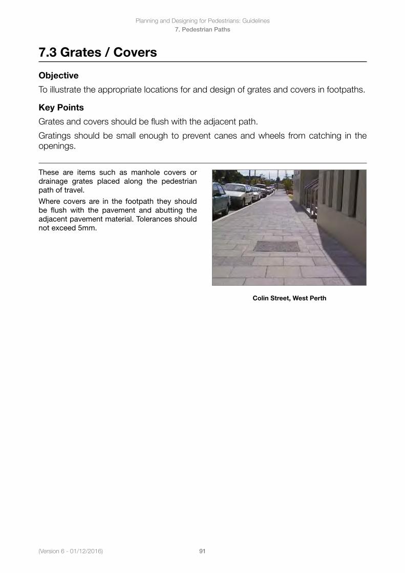
(Version 6 - 01/12/2016)
Planning and Designing for Pedestrians: Guidelines
91
7. Pedestrian Paths
7.3 Grates / Covers
Objective
To illustrate the appropriate locations for and design of grates and covers in footpaths.
Key Points
Grates and covers should be flush with the adjacent path.
Gratings should be small enough to prevent canes and wheels from catching in the openings.
These are items such as manhole covers or drainage grates placed along the pedestrian path of travel.
Where covers are in the footpath they should be flush with the pavement and abutting the adjacent pavement material. Tolerances should not exceed 5mm.
Colin Street, West Perth
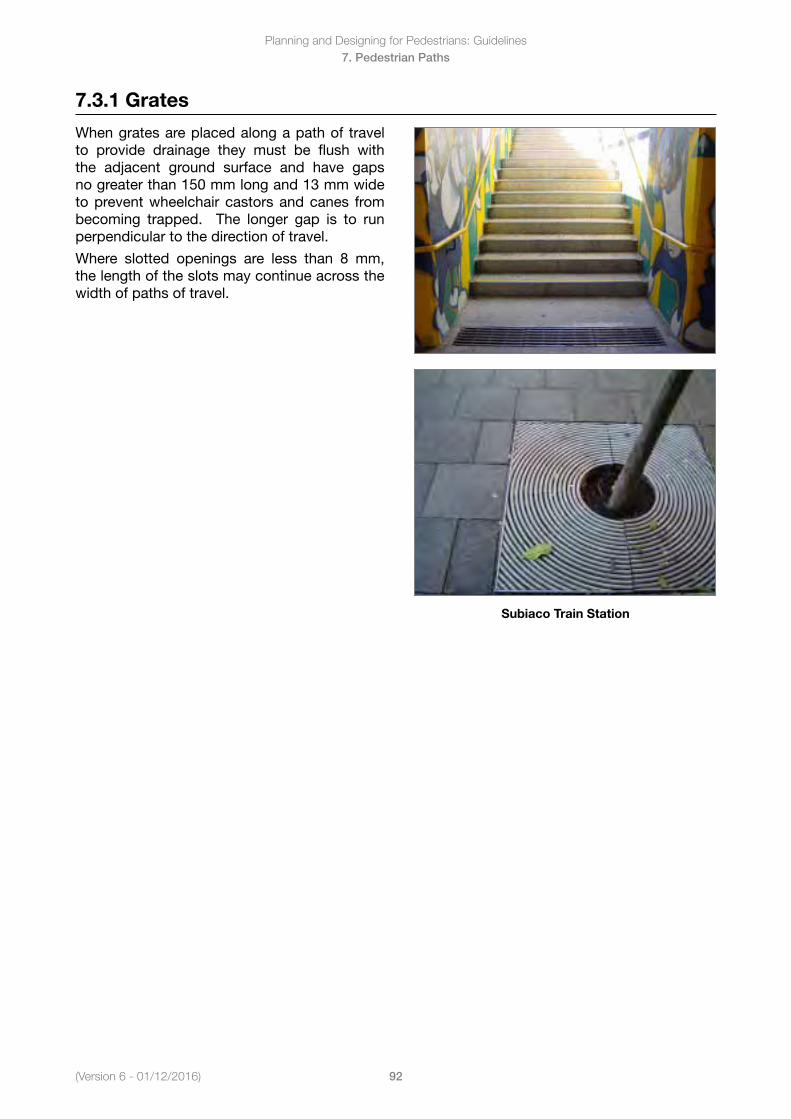
Planning and Designing for Pedestrians: Guidelines
92(Version 6 - 01/12/2016)
7. Pedestrian Paths
7.3.1 Grates
When grates are placed along a path of travel to provide drainage they must be flush with the adjacent ground surface and have gaps no greater than 150 mm long and 13 mm wide to prevent wheelchair castors and canes from becoming trapped. The longer gap is to run perpendicular to the direction of travel.
Where slotted openings are less than 8 mm, the length of the slots may continue across the width of paths of travel.
Subiaco Train Station
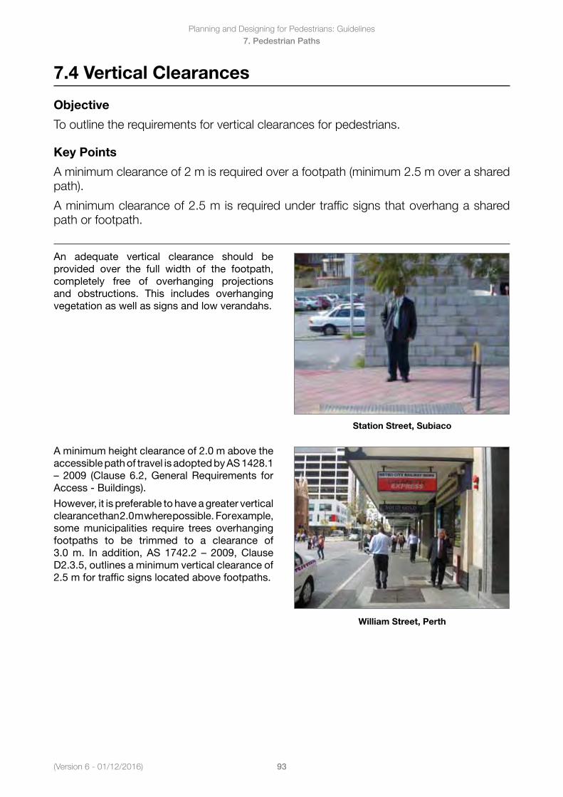
(Version 6 - 01/12/2016)
Planning and Designing for Pedestrians: Guidelines
93
7. Pedestrian Paths
7.4 Vertical Clearances
Objective
To outline the requirements for vertical clearances for pedestrians.
Key Points
A minimum clearance of 2 m is required over a footpath (minimum 2.5 m over a shared path).
A minimum clearance of 2.5 m is required under traffic signs that overhang a shared path or footpath.
An adequate vertical clearance should be provided over the full width of the footpath, completely free of overhanging projections and obstructions. This includes overhanging vegetation as well as signs and low verandahs.
Station Street, Subiaco
A minimum height clearance of 2.0 m above the accessible path of travel is adopted by AS 1428.1 – 2009 (Clause6.2,GeneralRequirements forAccess - Buildings).
However,itispreferabletohaveagreaterverticalclearance than 2.0 m where possible. For example, some municipalities require trees overhanging footpaths to be trimmed to a clearance of 3.0m. In addition, AS 1742.2 – 2009,ClauseD2.3.5, outlines a minimum vertical clearance of 2.5 m for traffic signs located above footpaths.
William Street, Perth
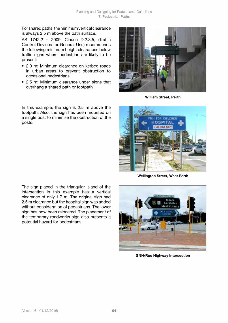
Planning and Designing for Pedestrians: Guidelines
94(Version 6 - 01/12/2016)
7. Pedestrian Paths
For shared paths, the minimum vertical clearance is always 2.5 m above the path surface.
AS 1742.2 – 2009, Clause D.2.3.5, (TrafficControl Devices for General Use) recommends the following minimum height clearances below traffic signs where pedestrian are likely to be present:
• 2.0m:Minimumclearanceonkerbedroadsin urban areas to prevent obstruction tooccasional pedestrians
• 2.5m:Minimumclearanceundersigns thatoverhang a shared path or footpath
William Street, Perth
In this example, the sign is 2.5 m above the footpath. Also, the sign has been mounted on a single post to minimise the obstruction of the posts.
Wellington Street, West Perth
The sign placed in the triangular island of the intersection in this example has a vertical clearance of only 1.7 m. The original sign had 2.5 m clearance but the hospital sign was added without consideration of pedestrians. The lower sign has now been relocated. The placement of the temporary roadworks sign also presents a potential hazard for pedestrians.
GNH/Roe Highway Intersection
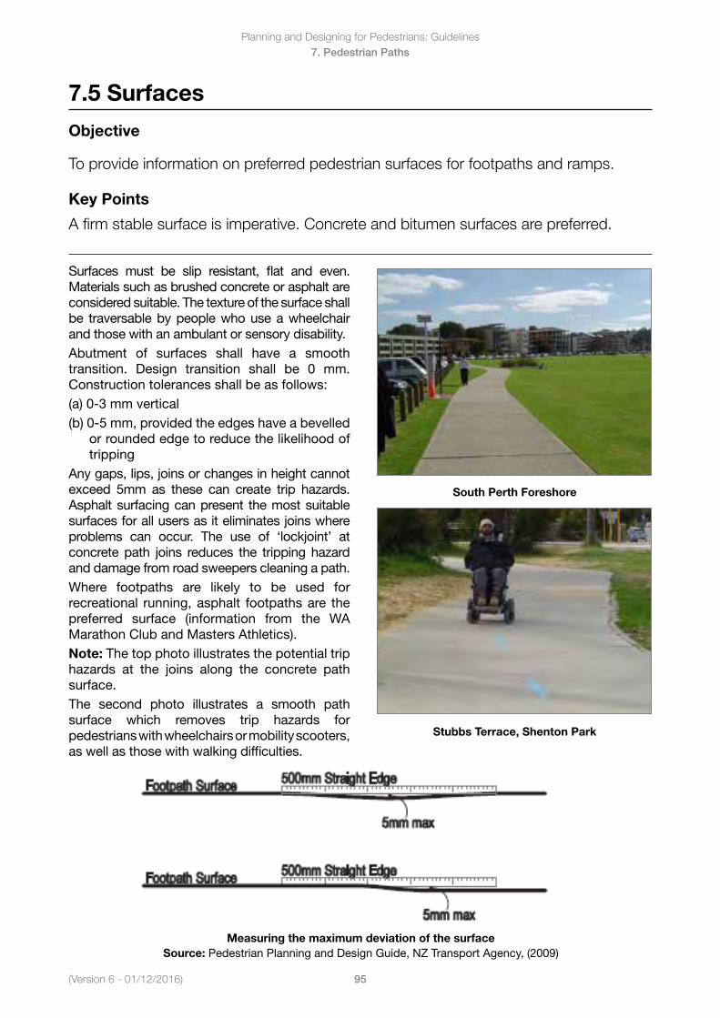
(Version 6 - 01/12/2016)
Planning and Designing for Pedestrians: Guidelines
95
7. Pedestrian Paths
7.5 Surfaces
Objective
To provide information on preferred pedestrian surfaces for footpaths and ramps.
Key Points
A firm stable surface is imperative. Concrete and bitumen surfaces are preferred.
Surfaces must be slip resistant, flat and even. Materials such as brushed concrete or asphalt are considered suitable. The texture of the surface shall be traversable by people who use a wheelchair and those with an ambulant or sensory disability.Abutment of surfaces shall have a smooth transition. Design transition shall be 0 mm. Construction tolerances shall be as follows:(a) 0-3 mm vertical(b) 0-5 mm, provided the edges have a bevelled
or rounded edge to reduce the likelihood of tripping
Any gaps, lips, joins or changes in height cannot exceed 5mm as these can create trip hazards. Asphalt surfacing can present the most suitable surfaces for all users as it eliminates joins where problems can occur. The use of ‘lockjoint’ at concrete path joins reduces the tripping hazard and damage from road sweepers cleaning a path.Where footpaths are likely to be used for recreational running, asphalt footpaths are the preferred surface (information from the WA Marathon Club and Masters Athletics).Note: The top photo illustrates the potential trip hazards at the joins along the concrete path surface.The second photo illustrates a smooth path surface which removes trip hazards for pedestrians with wheelchairs or mobility scooters, as well as those with walking difficulties.
South Perth Foreshore
Stubbs Terrace, Shenton Park
Measuring the maximum deviation of the surfaceSource: Pedestrian Planning and Design Guide, NZ Transport Agency, (2009)
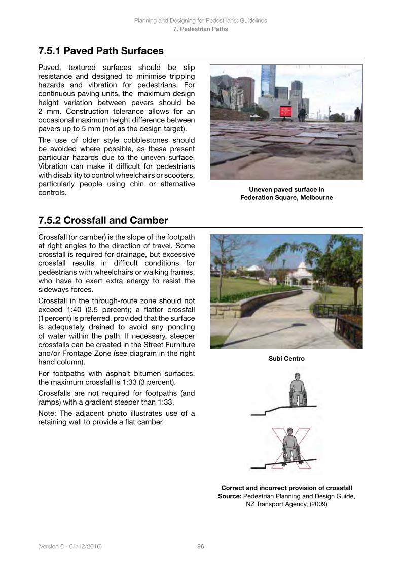
Planning and Designing for Pedestrians: Guidelines
96(Version 6 - 01/12/2016)
7. Pedestrian Paths
7.5.1 Paved Path Surfaces
Paved, textured surfaces should be slip resistance and designed to minimise tripping hazards and vibration for pedestrians. For continuous paving units, the maximum design height variation between pavers should be 2 mm. Construction tolerance allows for an occasional maximum height difference between pavers up to 5 mm (not as the design target).
The use of older style cobblestones should be avoided where possible, as these present particular hazards due to the uneven surface. Vibration can make it difficult for pedestrians with disability to control wheelchairs or scooters, particularly people using chin or alternative controls. Uneven paved surface in
Federation Square, Melbourne
7.5.2 Crossfall and Camber
Crossfall (or camber) is the slope of the footpath at right angles to the direction of travel. Some crossfall is required for drainage, but excessive crossfall results in difficult conditions for pedestrians with wheelchairs or walking frames, who have to exert extra energy to resist the sideways forces.
Crossfall in the through-route zone should not exceed 1:40 (2.5 percent); a flatter crossfall (1percent) is preferred, provided that the surface is adequately drained to avoid any ponding of water within the path. If necessary, steeper crossfalls can be created in the Street Furniture and/or Frontage Zone (see diagram in the right hand column).
For footpaths with asphalt bitumen surfaces, the maximum crossfall is 1:33 (3 percent).
Crossfalls are not required for footpaths (and ramps) with a gradient steeper than 1:33.
Note: The adjacent photo illustrates use of a retaining wall to provide a flat camber.
Subi Centro
Correct and incorrect provision of crossfall Source: Pedestrian Planning and Design Guide,
NZ Transport Agency, (2009)
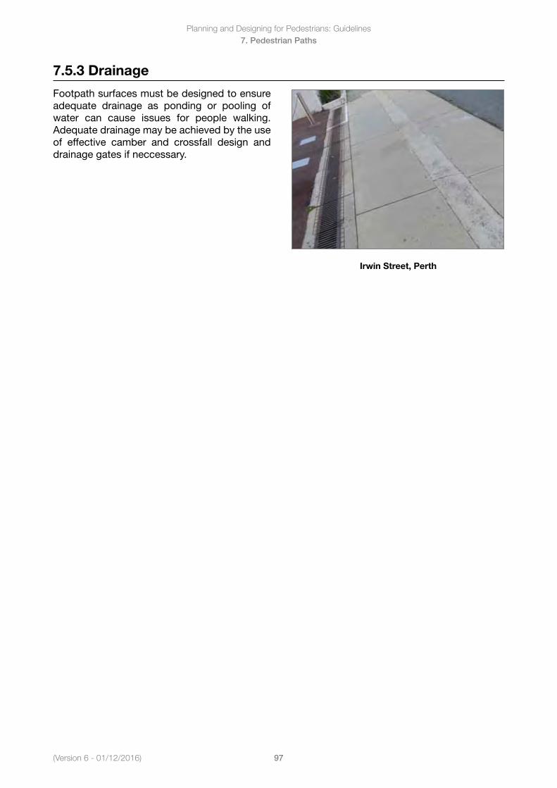
(Version 6 - 01/12/2016)
Planning and Designing for Pedestrians: Guidelines
97
7. Pedestrian Paths
7.5.3 Drainage
Footpath surfaces must be designed to ensure adequate drainage as ponding or pooling of water can cause issues for people walking. Adequate drainage may be achieved by the use of effective camber and crossfall design and drainage gates if neccessary.
Irwin Street, Perth
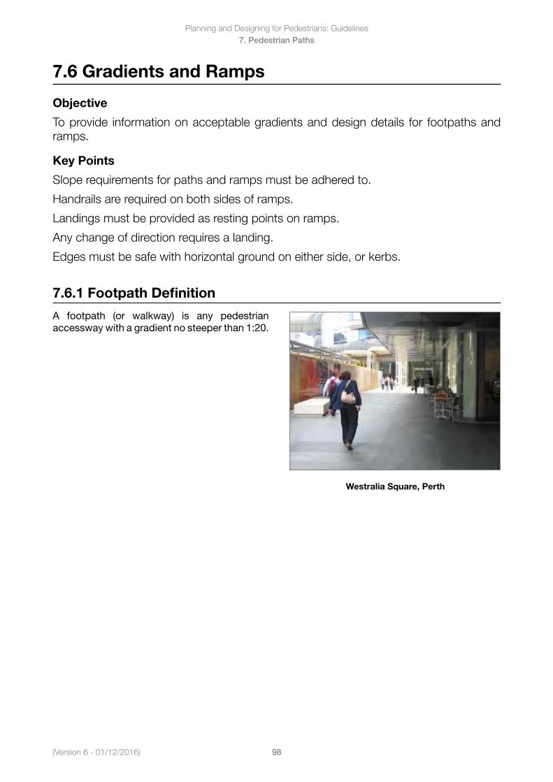
Planning and Designing for Pedestrians: Guidelines
98(Version 6 - 01/12/2016)
7. Pedestrian Paths
7.6 Gradients and Ramps
Objective
To provide information on acceptable gradients and design details for footpaths and ramps.
Key Points
Slope requirements for paths and ramps must be adhered to.
Handrails are required on both sides of ramps.
Landings must be provided as resting points on ramps.
Any change of direction requires a landing.
Edges must be safe with horizontal ground on either side, or kerbs.
7.6.1 Footpath Definition
A footpath (or walkway) is any pedestrian accessway with a gradient no steeper than 1:20.
Westralia Square, Perth
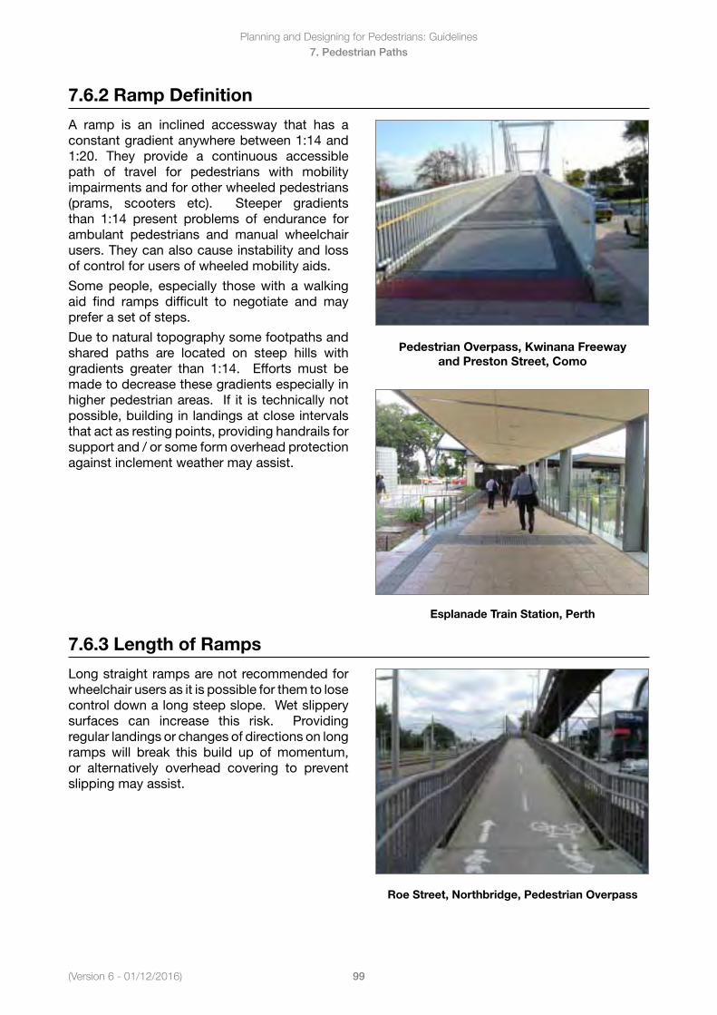
(Version 6 - 01/12/2016)
Planning and Designing for Pedestrians: Guidelines
99
7. Pedestrian Paths
7.6.2 Ramp Definition
A ramp is an inclined accessway that has a constant gradient anywhere between 1:14 and 1:20. They provide a continuous accessible path of travel for pedestrians with mobility impairments and for other wheeled pedestrians (prams, scooters etc). Steeper gradients than 1:14 present problems of endurance for ambulant pedestrians and manual wheelchair users. They can also cause instability and loss of control for users of wheeled mobility aids.
Some people, especially those with a walking aid find ramps difficult to negotiate and may prefer a set of steps.
Due to natural topography some footpaths and shared paths are located on steep hills with gradients greater than 1:14. Efforts must be made to decrease these gradients especially in higher pedestrian areas. If it is technically not possible, building in landings at close intervals that act as resting points, providing handrails for support and / or some form overhead protection against inclement weather may assist.
Pedestrian Overpass, Kwinana Freeway and Preston Street, Como
Esplanade Train Station, Perth
7.6.3 Length of Ramps
Long straight ramps are not recommended for wheelchair users as it is possible for them to lose control down a long steep slope. Wet slippery surfaces can increase this risk. Providing regular landings or changes of directions on long ramps will break this build up of momentum, or alternatively overhead covering to prevent slipping may assist.
Roe Street, Northbridge, Pedestrian Overpass
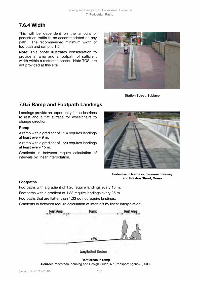
Planning and Designing for Pedestrians: Guidelines
100(Version 6 - 01/12/2016)
7. Pedestrian Paths
7.6.4 Width
This will be dependent on the amount of pedestrian traffic to be accommodated on any path. The recommended minimum width of footpath and ramp is 1.5 m.
Note: This photo illustrates consideration to provide a ramp and a footpath of sufficient width within a restricted space. Note TGSI are not provided at this site.
Station Street, Subiaco
7.6.5 Ramp and Footpath Landings
Landings provide an opportunity for pedestrians to rest and a flat surface for wheelchairs to change direction.
RampA ramp with a gradient of 1:14 requires landings at least every 9 m.
A ramp with a gradient of 1:20 requires landings at least every 15 m.
Gradients in between require calculation of intervals by linear interpolation.
Pedestrian Overpass, Kwinana Freeway and Preston Street, Como
FootpathsFootpaths with a gradient of 1:20 require landings every 15 m.
Footpaths with a gradient of 1:33 require landings every 25 m.
Footpaths that are flatter than 1:33 do not require landings.
Gradients in between require calculation of intervals by linear interpolation.
Rest areas in ramp Source: Pedestrian Planning and Design Guide, NZ Transport Agency, (2009)
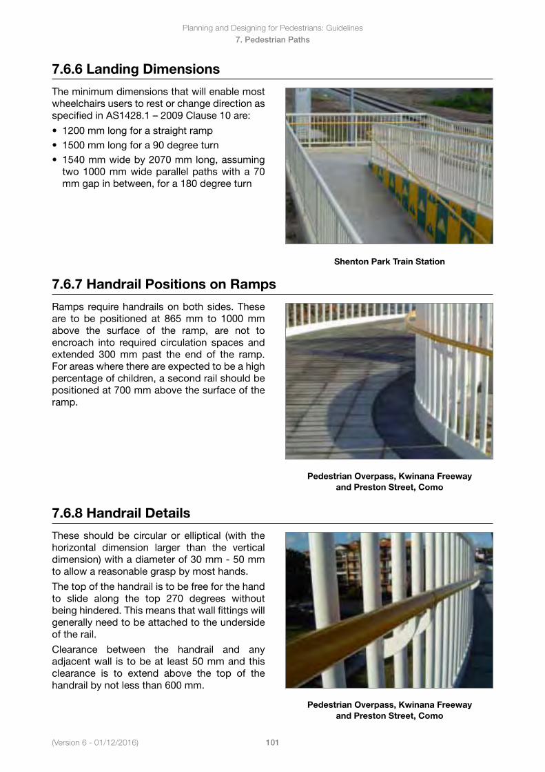
(Version 6 - 01/12/2016)
Planning and Designing for Pedestrians: Guidelines
101
7. Pedestrian Paths
7.6.6 Landing Dimensions
The minimum dimensions that will enable most wheelchairs users to rest or change direction as specifiedinAS1428.1–2009Clause10are:
• 1200mmlongforastraightramp• 1500mmlongfora90degreeturn• 1540mmwideby2070mmlong,assuming
two 1000 mm wide parallel paths with a 70mm gap in between, for a 180 degree turn
Shenton Park Train Station
7.6.7 Handrail Positions on Ramps
Ramps require handrails on both sides. These are to be positioned at 865 mm to 1000 mm above the surface of the ramp, are not to encroach into required circulation spaces and extended 300 mm past the end of the ramp. For areas where there are expected to be a high percentage of children, a second rail should be positioned at 700 mm above the surface of the ramp.
Pedestrian Overpass, Kwinana Freeway and Preston Street, Como
7.6.8 Handrail Details
These should be circular or elliptical (with the horizontal dimension larger than the vertical dimension) with a diameter of 30 mm - 50 mm to allow a reasonable grasp by most hands.
The top of the handrail is to be free for the hand to slide along the top 270 degrees without being hindered. This means that wall fittings will generally need to be attached to the underside of the rail.
Clearance between the handrail and any adjacent wall is to be at least 50 mm and this clearance is to extend above the top of the handrail by not less than 600 mm.
Pedestrian Overpass, Kwinana Freeway and Preston Street, Como
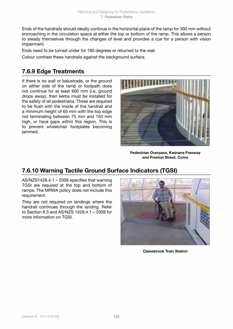
Planning and Designing for Pedestrians: Guidelines
102(Version 6 - 01/12/2016)
7. Pedestrian Paths
Ends of the handrails should ideally continue in the horizontal plane of the ramp for 300 mm without encroaching in the circulation space at either the top or bottom of the ramp. This allows a person to steady themselves through the changes of level and provides a cue for a person with vision impairment.
Ends need to be turned under for 180 degrees or returned to the wall.
Colour contrast these handrails against the background surface.
7.6.9 Edge Treatments
If there is no wall or balustrade, or the ground on either side of the ramp or footpath does not continue for at least 600 mm (i.e. ground drops away), then kerbs must be installed for the safety of all pedestrians. These are required to be flush with the inside of the handrail and a minimum height of 65 mm with the top edge not terminating between 75 mm and 150 mm high, or have gaps within this region. This is to prevent wheelchair footplates becoming jammed.
Pedestrian Overpass, Kwinana Freeway and Preston Street, Como
7.6.10 Warning Tactile Ground Surface Indicators (TGSI)
AS/NZS1428.4.1–2009specifiesthatwarningTGSI are required at the top and bottom of ramps. The MRWA policy does not include this requirement.
They are not required on landings where the handrail continues through the landing. Refer toSection8.3andAS/NZS1428.4.1–2009formore information on TGSI.
Claisebrook Train Station
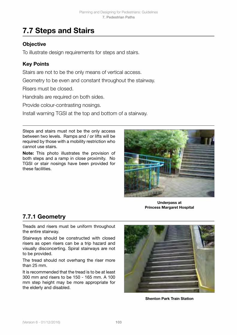
(Version 6 - 01/12/2016)
Planning and Designing for Pedestrians: Guidelines
103
7. Pedestrian Paths
7.7 Steps and Stairs
Objective
To illustrate design requirements for steps and stairs.
Key Points
Stairs are not to be the only means of vertical access.
Geometry to be even and constant throughout the stairway.
Risers must be closed.
Handrails are required on both sides.
Provide colour-contrasting nosings.
Install warning TGSI at the top and bottom of a stairway.
Steps and stairs must not be the only access between two levels. Ramps and / or lifts will be required by those with a mobility restriction who cannot use stairs.
Note: This photo illustrates the provision of both steps and a ramp in close proximity. No TGSI or stair nosings have been provided for these facilities.
Underpass at Princess Margaret Hospital
7.7.1 Geometry
Treads and risers must be uniform throughout the entire stairway.
Stairways should be constructed with closed risers as open risers can be a trip hazard and visually disconcerting. Spiral stairways are not to be provided.
The tread should not overhang the riser more than 25 mm.
It is recommended that the tread is to be at least 300 mm and risers to be 150 - 165 mm. A 100 mm step height may be more appropriate for the elderly and disabled.
Shenton Park Train Station
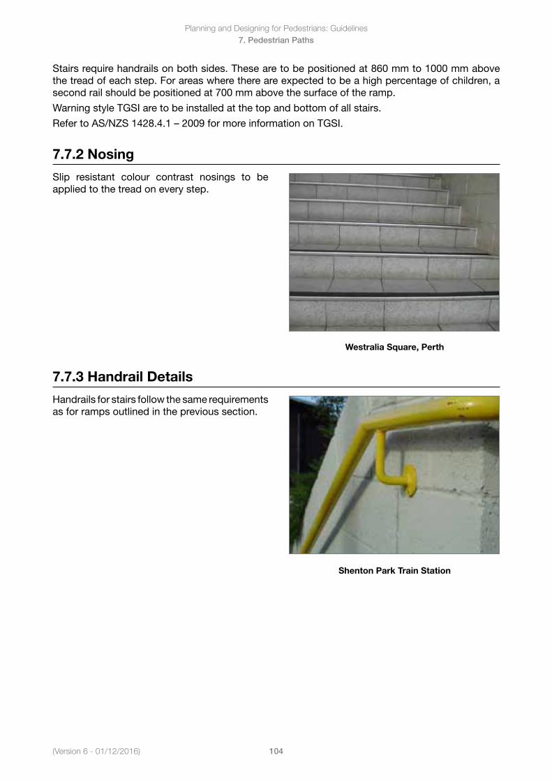
Planning and Designing for Pedestrians: Guidelines
104(Version 6 - 01/12/2016)
7. Pedestrian Paths
Stairs require handrails on both sides. These are to be positioned at 860 mm to 1000 mm above the tread of each step. For areas where there are expected to be a high percentage of children, a second rail should be positioned at 700 mm above the surface of the ramp.
Warning style TGSI are to be installed at the top and bottom of all stairs.
RefertoAS/NZS1428.4.1–2009formoreinformationonTGSI.
7.7.2 Nosing
Slip resistant colour contrast nosings to be applied to the tread on every step.
Westralia Square, Perth
7.7.3 Handrail Details
Handrailsforstairsfollowthesamerequirementsas for ramps outlined in the previous section.
Shenton Park Train Station
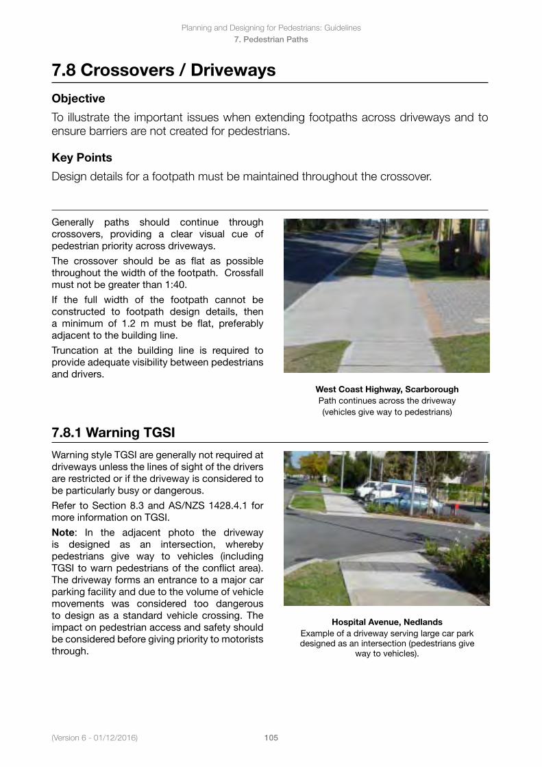
(Version 6 - 01/12/2016)
Planning and Designing for Pedestrians: Guidelines
105
7. Pedestrian Paths
7.8 Crossovers / Driveways
Objective
To illustrate the important issues when extending footpaths across driveways and to ensure barriers are not created for pedestrians.
Key Points
Design details for a footpath must be maintained throughout the crossover.
Generally paths should continue through crossovers, providing a clear visual cue of pedestrian priority across driveways.
The crossover should be as flat as possible throughout the width of the footpath. Crossfall must not be greater than 1:40.
If the full width of the footpath cannot be constructed to footpath design details, then a minimum of 1.2 m must be flat, preferably adjacent to the building line.
Truncation at the building line is required to provide adequate visibility between pedestrians and drivers.
West Coast Highway, ScarboroughPath continues across the driveway (vehicles give way to pedestrians)
7.8.1 Warning TGSI
Warning style TGSI are generally not required at driveways unless the lines of sight of the drivers are restricted or if the driveway is considered to be particularly busy or dangerous.
Refer to Section 8.3 and AS/NZS 1428.4.1 for more information on TGSI.
Note: In the adjacent photo the driveway is designed as an intersection, whereby pedestrians give way to vehicles (including TGSI to warn pedestrians of the conflict area). The driveway forms an entrance to a major car parking facility and due to the volume of vehicle movements was considered too dangerous to design as a standard vehicle crossing. The impact on pedestrian access and safety should be considered before giving priority to motorists through.
Hospital Avenue, NedlandsExample of a driveway serving large car park designed as an intersection (pedestrians give
way to vehicles).
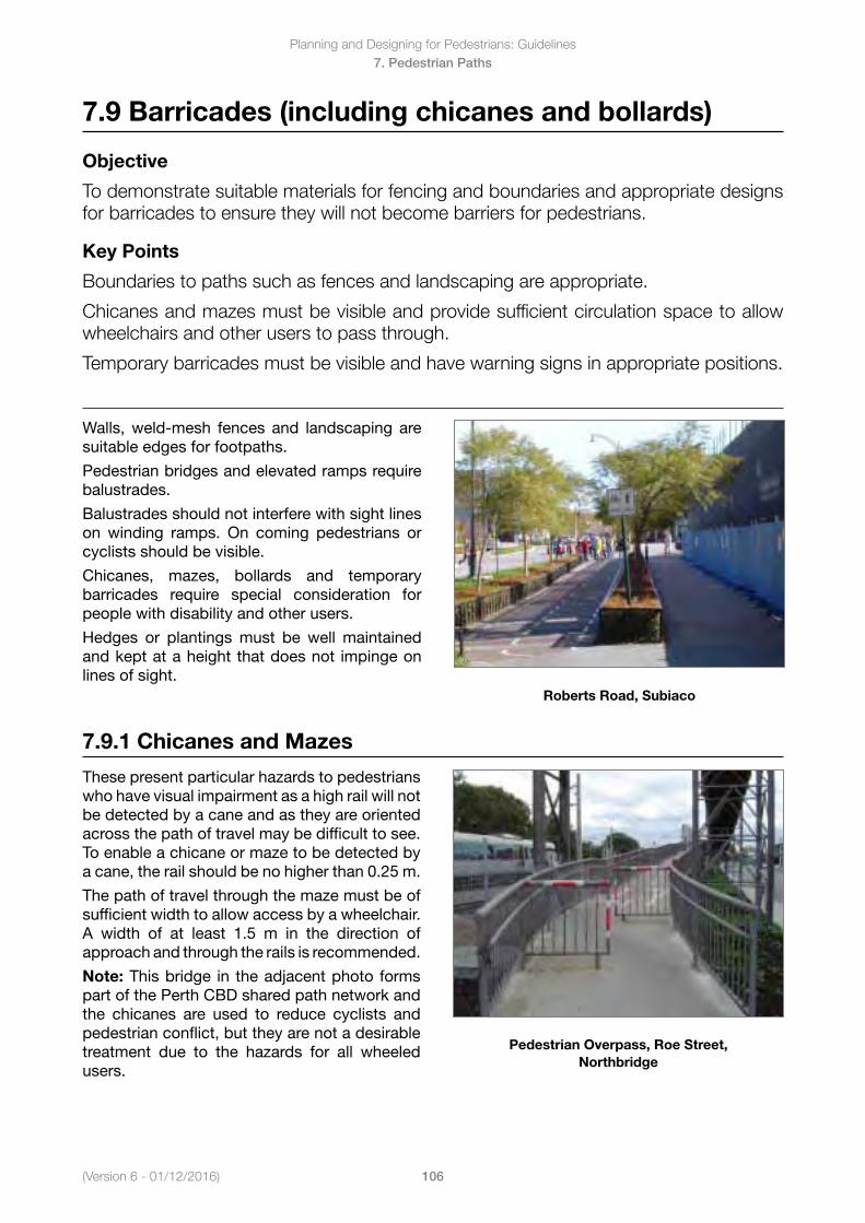
Planning and Designing for Pedestrians: Guidelines
106(Version 6 - 01/12/2016)
7. Pedestrian Paths
7.9 Barricades (including chicanes and bollards)
Objective
To demonstrate suitable materials for fencing and boundaries and appropriate designs for barricades to ensure they will not become barriers for pedestrians.
Key Points
Boundaries to paths such as fences and landscaping are appropriate.
Chicanes and mazes must be visible and provide sufficient circulation space to allow wheelchairs and other users to pass through.
Temporary barricades must be visible and have warning signs in appropriate positions.
Walls, weld-mesh fences and landscaping are suitable edges for footpaths.
Pedestrian bridges and elevated ramps require balustrades.
Balustrades should not interfere with sight lines on winding ramps. On coming pedestrians or cyclists should be visible.
Chicanes, mazes, bollards and temporary barricades require special consideration for people with disability and other users.
Hedges or plantingsmust be well maintainedand kept at a height that does not impinge on lines of sight.
Roberts Road, Subiaco
7.9.1 Chicanes and Mazes
These present particular hazards to pedestrians who have visual impairment as a high rail will not be detected by a cane and as they are oriented across the path of travel may be difficult to see. To enable a chicane or maze to be detected by a cane, the rail should be no higher than 0.25 m.
The path of travel through the maze must be of sufficient width to allow access by a wheelchair. A width of at least 1.5 m in the direction of approach and through the rails is recommended.
Note: This bridge in the adjacent photo forms part of the Perth CBD shared path network and the chicanes are used to reduce cyclists and pedestrian conflict, but they are not a desirable treatment due to the hazards for all wheeled users.
Pedestrian Overpass, Roe Street, Northbridge
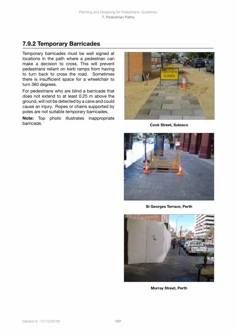
(Version 6 - 01/12/2016)
Planning and Designing for Pedestrians: Guidelines
107
7. Pedestrian Paths
7.9.2 Temporary Barricades
Temporary barricades must be well signed at locations in the path where a pedestrian can make a decision to cross. This will prevent pedestrians reliant on kerb ramps from having to turn back to cross the road. Sometimes there is insufficient space for a wheelchair to turn 360 degrees.
For pedestrians who are blind a barricade that does not extend to at least 0.25 m above the ground, will not be detected by a cane and could cause an injury. Ropes or chains supported by poles are not suitable temporary barricades.
Note: Top photo illustrates inappropriate barricade. Cook Street, Subiaco
St Georges Terrace, Perth
Murray Street, Perth
Planning and Designing for Pedestrians: Guidelines
108(Version 6 - 01/12/2016)
8. Pedestrian Crossing Elements
8. Pedestrian Crossing Elements
In this Section
8.1 Kerb Crossing Ramps and Pedestrian Cut-Throughs 8.1.1 Alignment and Surface of Kerb Ramps
8.1.2 Gradient and Length of Kerb Ramps
8.1.3 Camber of Kerb Ramps
8.1.4 Landings at Kerb Ramps
8.1.5 Type A Kerb Ramp
8.1.6 Type B Kerb Ramp
8.1.7 Description of Pedestrian Cut-Throughs
8.1.8 Alignment of Cut-Through
8.1.9 Width of Pedestrian Cut-Throughs
8.1.10 Transition of Cut-Throughs
8.2 Grab Rails 8.2.1 Design
8.2.2 Location
8.3 Tactile Ground Surface Indicators 8.3.1 Consultation with User Groups
8.3.2 Types of TGSI
8.3.3 Warning TGSI
8.3.4 Warning TGSI Applications
8.3.5 Directional TGSI
8.3.6 TGSI at Kerb Ramps
8.3.7 TGSI at Bus Stops
8.3.8 TGSI at Cut-Throughs
8.4 Audible/Tactile Pedestrian Signals 8.4.1 Usage
8.4.2 Position of Push Button Assembly
8.4.3 Push Button Orientation
8.4.4 Push Button Orientation for Exclusive Pedestrian Phases
8.4.5 Push Button Orientation for Parallel Pedestrian Phases
8.4.6 Circulation Space
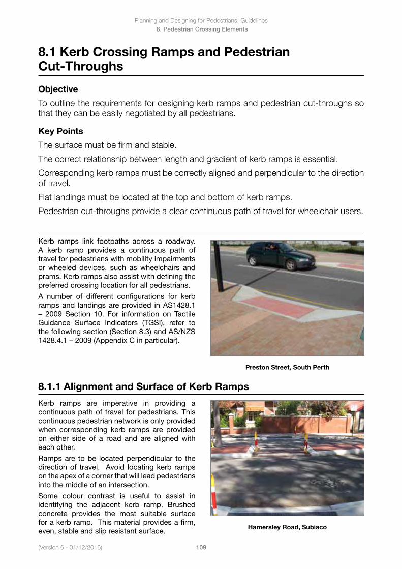
(Version 6 - 01/12/2016)
Planning and Designing for Pedestrians: Guidelines
109
8. Pedestrian Crossing Elements
8.1 Kerb Crossing Ramps and Pedestrian Cut-Throughs
Objective
To outline the requirements for designing kerb ramps and pedestrian cut-throughs so that they can be easily negotiated by all pedestrians.
Key Points
The surface must be firm and stable.
The correct relationship between length and gradient of kerb ramps is essential.
Corresponding kerb ramps must be correctly aligned and perpendicular to the direction of travel.
Flat landings must be located at the top and bottom of kerb ramps.
Pedestrian cut-throughs provide a clear continuous path of travel for wheelchair users.
Kerb ramps link footpaths across a roadway. A kerb ramp provides a continuous path of travel for pedestrians with mobility impairments or wheeled devices, such as wheelchairs and prams. Kerb ramps also assist with defining the preferred crossing location for all pedestrians.
A number of different configurations for kerb ramps and landings are provided in AS1428.1 – 2009 Section 10. For information on TactileGuidance Surface Indicators (TGSI), refer to the following section (Section 8.3) and AS/NZS 1428.4.1–2009(AppendixCinparticular).
Preston Street, South Perth
8.1.1 Alignment and Surface of Kerb Ramps
Kerb ramps are imperative in providing a continuous path of travel for pedestrians. This continuous pedestrian network is only provided when corresponding kerb ramps are provided on either side of a road and are aligned with each other.
Ramps are to be located perpendicular to the direction of travel. Avoid locating kerb ramps on the apex of a corner that will lead pedestrians into the middle of an intersection.
Some colour contrast is useful to assist in identifying the adjacent kerb ramp. Brushed concrete provides the most suitable surface for a kerb ramp. This material provides a firm, even, stable and slip resistant surface. Hamersley Road, Subiaco
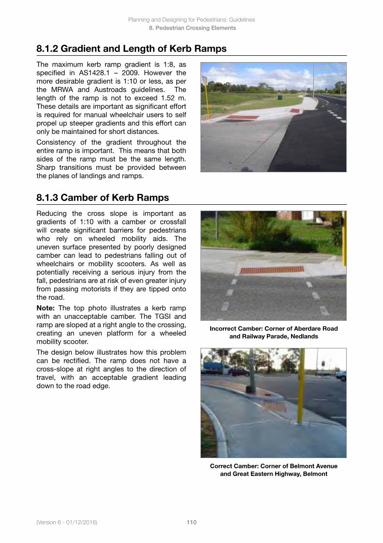
Planning and Designing for Pedestrians: Guidelines
110(Version 6 - 01/12/2016)
8. Pedestrian Crossing Elements
8.1.2 Gradient and Length of Kerb Ramps
The maximum kerb ramp gradient is 1:8, as specified in AS1428.1 – 2009. However themore desirable gradient is 1:10 or less, as per the MRWA and Austroads guidelines. The length of the ramp is not to exceed 1.52 m. These details are important as significant effort is required for manual wheelchair users to self propel up steeper gradients and this effort can only be maintained for short distances.
Consistency of the gradient throughout the entire ramp is important. This means that both sides of the ramp must be the same length. Sharp transitions must be provided between the planes of landings and ramps.
8.1.3 Camber of Kerb Ramps
Reducing the cross slope is important as gradients of 1:10 with a camber or crossfall will create significant barriers for pedestrians who rely on wheeled mobility aids. The uneven surface presented by poorly designed camber can lead to pedestrians falling out of wheelchairs or mobility scooters. As well as potentially receiving a serious injury from the fall, pedestrians are at risk of even greater injury from passing motorists if they are tipped onto the road.
Note: The top photo illustrates a kerb ramp with an unacceptable camber. The TGSI and ramp are sloped at a right angle to the crossing, creating an uneven platform for a wheeled mobility scooter.
The design below illustrates how this problem can be rectified. The ramp does not have a cross-slope at right angles to the direction of travel, with an acceptable gradient leading down to the road edge.
Incorrect Camber: Corner of Aberdare Road and Railway Parade, Nedlands
Correct Camber: Corner of Belmont Avenue and Great Eastern Highway, Belmont
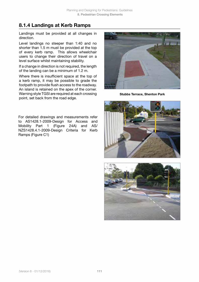
(Version 6 - 01/12/2016)
Planning and Designing for Pedestrians: Guidelines
111
8. Pedestrian Crossing Elements
8.1.4 Landings at Kerb Ramps
Landings must be provided at all changes in direction.
Level landings no steeper than 1:40 and no shorter than 1.5 m must be provided at the top of every kerb ramp. This allows wheelchair users to change their direction of travel on a level surface whilst maintaining stability.
If a change in direction is not required, the length of the landing can be a minimum of 1.2 m.
Where there is insufficient space at the top of a kerb ramp, it may be possible to grade the footpath to provide flush access to the roadway. An island is retained on the apex of the corner. Warning style TGSI are required at each crossing point, set back from the road edge.
Stubbs Terrace, Shenton Park
For detailed drawings and measurements refer to AS1428.1-2009-Design for Access and Mobility Part 1 (Figure 24A) and AS/NZS1428.4.1-2009-Design Criteria for Kerb Ramps (Figure C1)
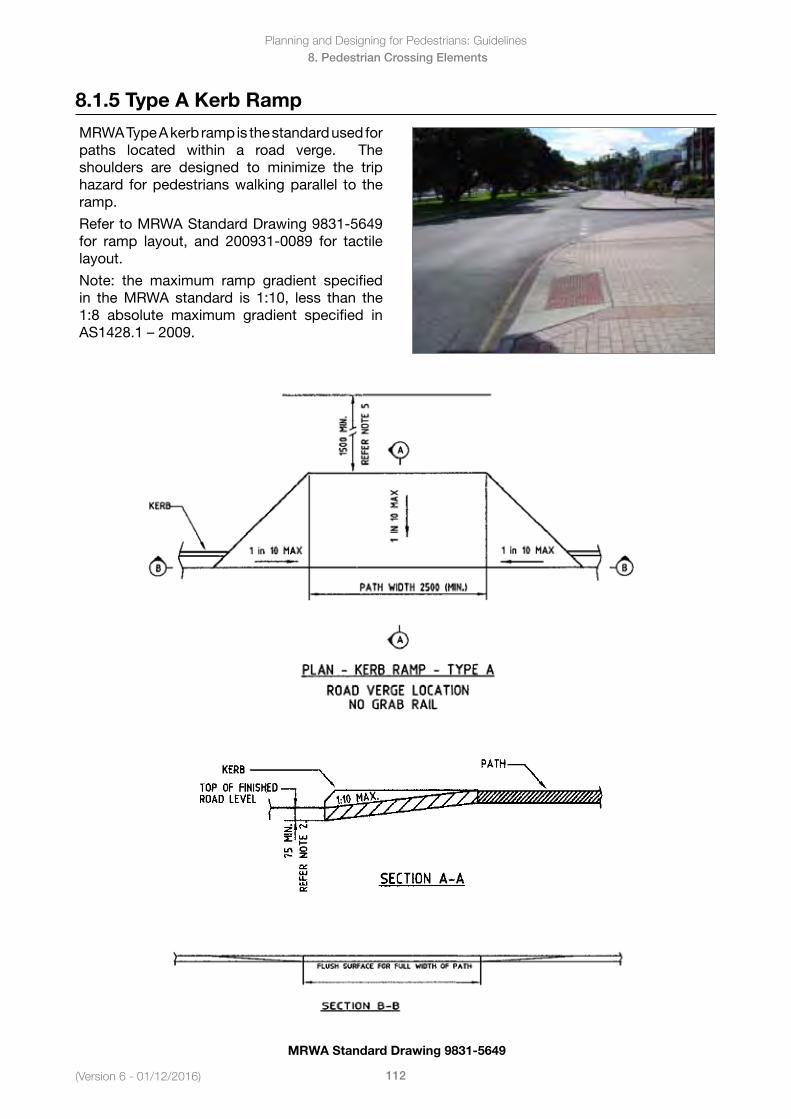
Planning and Designing for Pedestrians: Guidelines
112(Version 6 - 01/12/2016)
8. Pedestrian Crossing Elements
8.1.5 Type A Kerb Ramp
MRWA Type A kerb ramp is the standard used for paths located within a road verge. The shoulders are designed to minimize the trip hazard for pedestrians walking parallel to the ramp.
Refer to MRWA Standard Drawing 9831-5649 for ramp layout, and 200931-0089 for tactile layout.
Note: the maximum ramp gradient specified in the MRWA standard is 1:10, less than the 1:8 absolute maximum gradient specified in AS1428.1–2009.
MRWA Standard Drawing 9831-5649
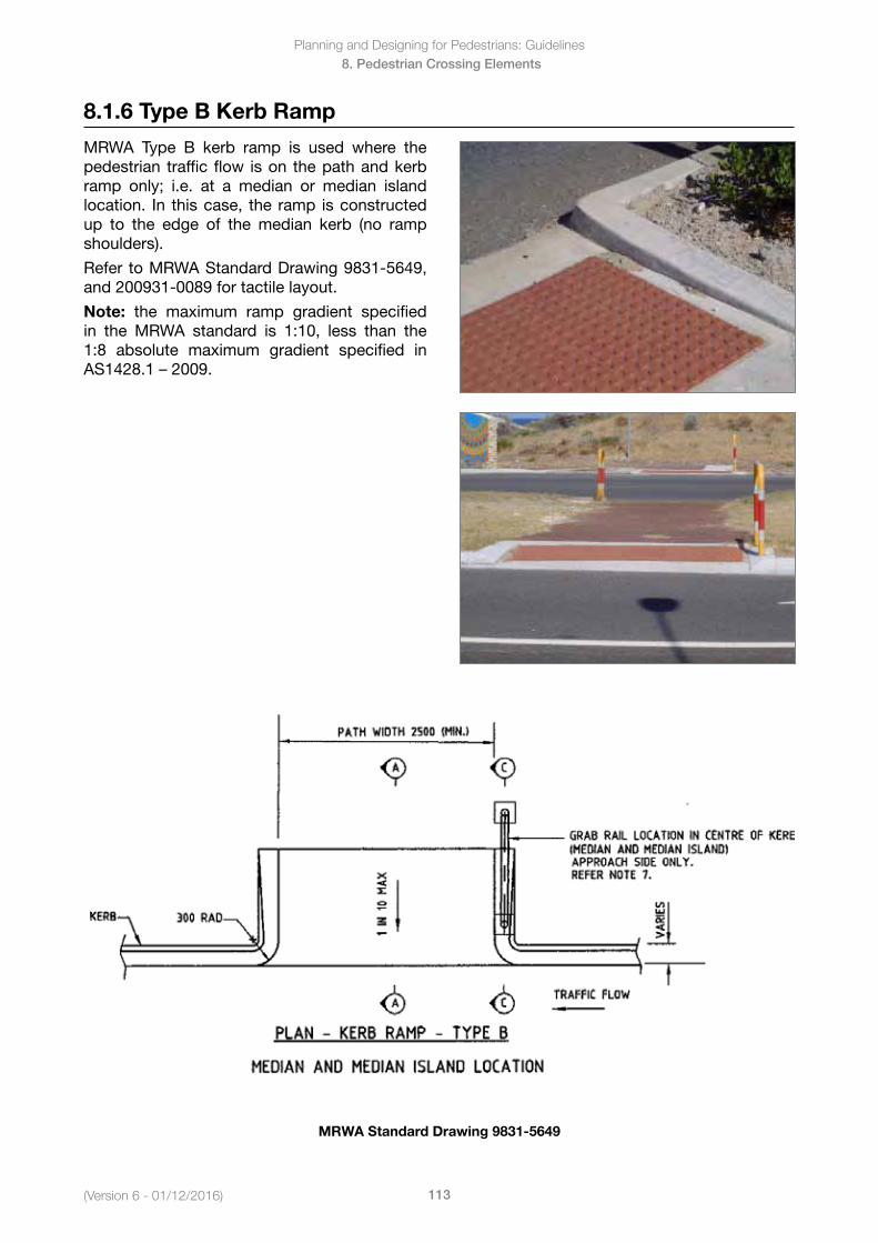
(Version 6 - 01/12/2016)
Planning and Designing for Pedestrians: Guidelines
113
8. Pedestrian Crossing Elements
8.1.6 Type B Kerb Ramp
MRWA Type B kerb ramp is used where the pedestrian traffic flow is on the path and kerb ramp only; i.e. at a median or median island location. In this case, the ramp is constructed up to the edge of the median kerb (no ramp shoulders).
Refer to MRWA Standard Drawing 9831-5649, and 200931-0089 for tactile layout.
Note: the maximum ramp gradient specified in the MRWA standard is 1:10, less than the 1:8 absolute maximum gradient specified in AS1428.1–2009.
MRWA Standard Drawing 9831-5649
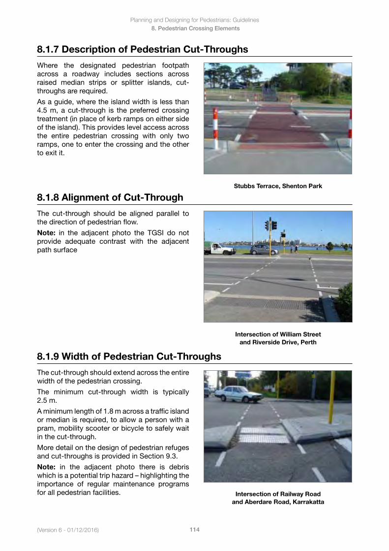
Planning and Designing for Pedestrians: Guidelines
114(Version 6 - 01/12/2016)
8. Pedestrian Crossing Elements
8.1.7 Description of Pedestrian Cut-Throughs
Where the designated pedestrian footpath across a roadway includes sections across raised median strips or splitter islands, cut-throughs are required.
As a guide, where the island width is less than 4.5 m, a cut-through is the preferred crossing treatment (in place of kerb ramps on either side of the island). This provides level access across the entire pedestrian crossing with only two ramps, one to enter the crossing and the other to exit it.
Stubbs Terrace, Shenton Park
8.1.8 Alignment of Cut-Through
The cut-through should be aligned parallel to the direction of pedestrian flow.
Note: in the adjacent photo the TGSI do not provide adequate contrast with the adjacent path surface
Intersection of William Street and Riverside Drive, Perth
8.1.9 Width of Pedestrian Cut-Throughs
The cut-through should extend across the entire width of the pedestrian crossing.
The minimum cut-through width is typically 2.5 m.
A minimum length of 1.8 m across a traffic island or median is required, to allow a person with a pram, mobility scooter or bicycle to safely wait in the cut-through.
More detail on the design of pedestrian refuges and cut-throughs is provided in Section 9.3.
Note: in the adjacent photo there is debris whichisapotentialtriphazard–highlightingtheimportance of regular maintenance programs for all pedestrian facilities. Intersection of Railway Road
and Aberdare Road, Karrakatta
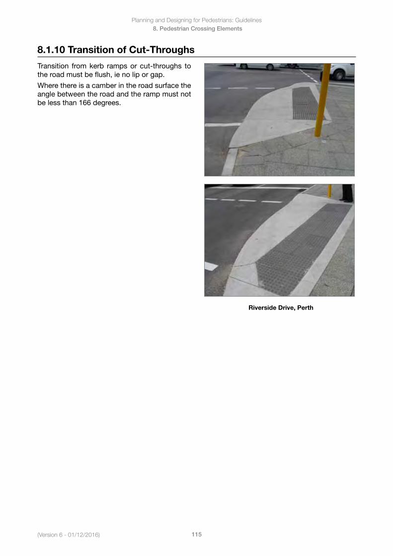
(Version 6 - 01/12/2016)
Planning and Designing for Pedestrians: Guidelines
115
8. Pedestrian Crossing Elements
8.1.10 Transition of Cut-Throughs
Transition from kerb ramps or cut-throughs to the road must be flush, ie no lip or gap.
Where there is a camber in the road surface the angle between the road and the ramp must not be less than 166 degrees.
Riverside Drive, Perth
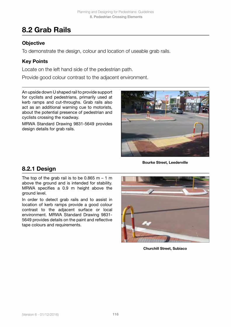
Planning and Designing for Pedestrians: Guidelines
116(Version 6 - 01/12/2016)
8. Pedestrian Crossing Elements
8.2 Grab Rails
Objective
To demonstrate the design, colour and location of useable grab rails.
Key Points
Locate on the left hand side of the pedestrian path.
Provide good colour contrast to the adjacent environment.
An upside down U shaped rail to provide support for cyclists and pedestrians, primarily used at kerb ramps and cut-throughs. Grab rails also act as an additional warning cue to motorists, about the potential presence of pedestrian and cyclists crossing the roadway.
MRWA Standard Drawing 9831-5649 provides design details for grab rails.
Bourke Street, Leederville
8.2.1 Design
Thetopofthegrabrailistobe0.865m–1mabove the ground and is intended for stability. MRWA specifies a 0.9 m height above the ground level.
In order to detect grab rails and to assist in location of kerb ramps provide a good colour contrast to the adjacent surface or local environment. MRWA Standard Drawing 9831-5649 provides details on the paint and reflective tape colours and requirements.
Churchill Street, Subiaco
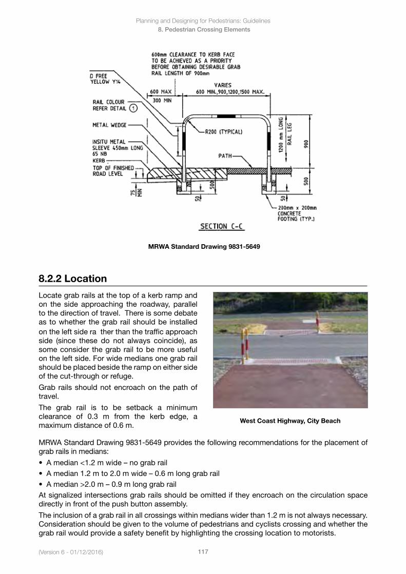
(Version 6 - 01/12/2016)
Planning and Designing for Pedestrians: Guidelines
117
8. Pedestrian Crossing Elements
8.2.2 Location
Locate grab rails at the top of a kerb ramp and on the side approaching the roadway, parallel to the direction of travel. There is some debate as to whether the grab rail should be installed on the left side ra ther than the traffic approach side (since these do not always coincide), as some consider the grab rail to be more useful on the left side. For wide medians one grab rail should be placed beside the ramp on either side of the cut-through or refuge.
Grab rails should not encroach on the path of travel.
The grab rail is to be setback a minimum clearance of 0.3 m from the kerb edge, a maximum distance of 0.6 m.
West Coast Highway, City Beach
MRWA Standard Drawing 9831-5649 provides the following recommendations for the placement of grab rails in medians:
• Amedian<1.2mwide–nograbrail• Amedian1.2mto2.0mwide–0.6mlonggrabrail• Amedian>2.0m–0.9mlonggrabrailAt signalized intersections grab rails should be omitted if they encroach on the circulation space directly in front of the push button assembly.
The inclusion of a grab rail in all crossings within medians wider than 1.2 m is not always necessary. Consideration should be given to the volume of pedestrians and cyclists crossing and whether the grab rail would provide a safety benefit by highlighting the crossing location to motorists.
MRWA Standard Drawing 9831-5649
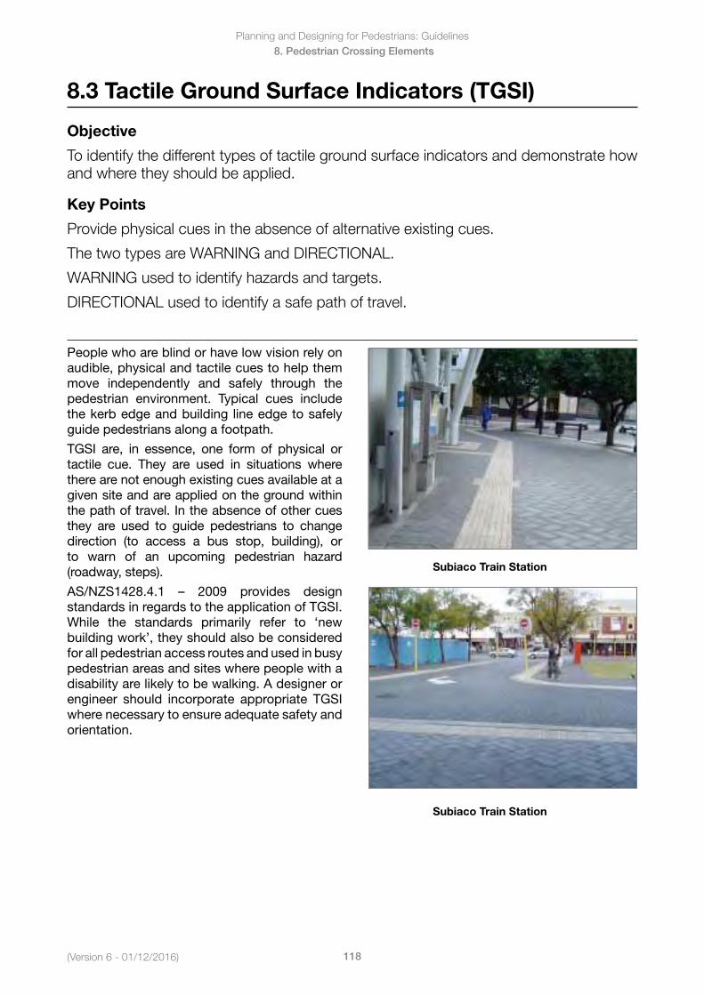
Planning and Designing for Pedestrians: Guidelines
118(Version 6 - 01/12/2016)
8. Pedestrian Crossing Elements
8.3 Tactile Ground Surface Indicators (TGSI)
Objective
To identify the different types of tactile ground surface indicators and demonstrate how and where they should be applied.
Key Points
Provide physical cues in the absence of alternative existing cues.
The two types are WARNING and DIRECTIONAL.
WARNING used to identify hazards and targets.
DIRECTIONAL used to identify a safe path of travel.
People who are blind or have low vision rely on audible, physical and tactile cues to help them move independently and safely through the pedestrian environment. Typical cues include the kerb edge and building line edge to safely guide pedestrians along a footpath.
TGSI are, in essence, one form of physical or tactile cue. They are used in situations where there are not enough existing cues available at a given site and are applied on the ground within the path of travel. In the absence of other cues they are used to guide pedestrians to change direction (to access a bus stop, building), or to warn of an upcoming pedestrian hazard (roadway, steps).
AS/NZS1428.4.1 – 2009 provides designstandards in regards to the application of TGSI. While the standards primarily refer to ‘new building work’, they should also be considered for all pedestrian access routes and used in busy pedestrian areas and sites where people with a disability are likely to be walking. A designer or engineer should incorporate appropriate TGSI where necessary to ensure adequate safety and orientation.
Subiaco Train Station
Subiaco Train Station
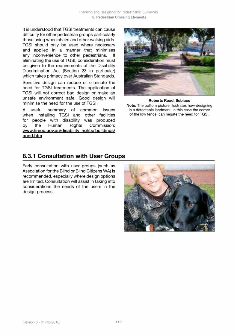
(Version 6 - 01/12/2016)
Planning and Designing for Pedestrians: Guidelines
119
8. Pedestrian Crossing Elements
It is understood that TGSI treatments can cause difficulty for other pedestrian groups particularly those using wheelchairs and other walking aids. TGSI should only be used where necessary and applied in a manner that minimises any inconvenience to other pedestrians. If eliminating the use of TGSI, consideration must be given to the requirements of the Disability Discrimination Act (Section 23 in particular) which takes primacy over Australian Standards.
Sensitive design can reduce or eliminate the need for TGSI treatments. The application of TGSI will not correct bad design or make an unsafe environment safe. Good design will minimise the need for the use of TGSI.
A useful summary of common issues when installing TGSI and other facilities for people with disability was produced by the Human Rights Commission: www.hreoc.gov.au/disability_rights/ buildings/good.htm
Roberts Road, SubiacoNote: The bottom picture illustrates how designing
in a detectable landmark, in this case the corner of the low fence, can negate the need for TGSI.
8.3.1 Consultation with User Groups
Early consultation with user groups (such as Association for the Blind or Blind Citizens WA) is recommended, especially where design options are limited. Consultation will assist in taking into considerations the needs of the users in the design process.
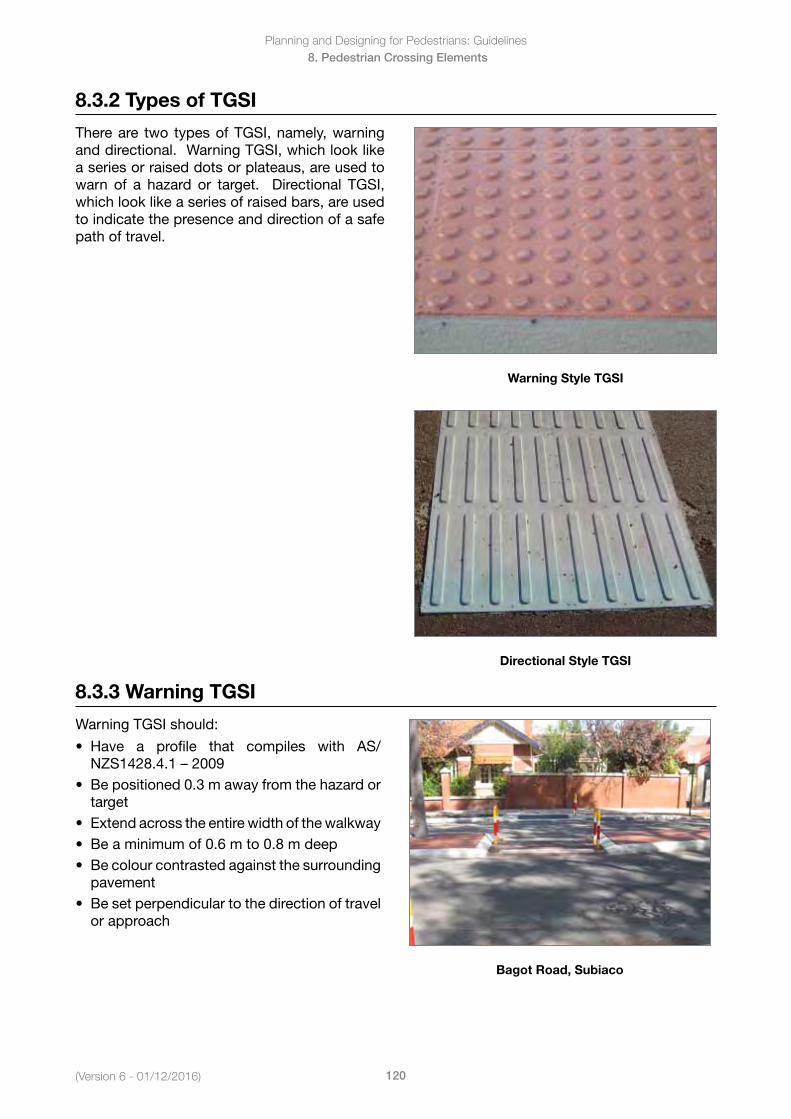
Planning and Designing for Pedestrians: Guidelines
120(Version 6 - 01/12/2016)
8. Pedestrian Crossing Elements
8.3.2 Types of TGSI
There are two types of TGSI, namely, warning and directional. Warning TGSI, which look like a series or raised dots or plateaus, are used to warn of a hazard or target. Directional TGSI, which look like a series of raised bars, are used to indicate the presence and direction of a safe path of travel.
Warning Style TGSI
Directional Style TGSI
8.3.3 Warning TGSI
Warning TGSI should:
• Have a profile that compiles with AS/NZS1428.4.1–2009
• Bepositioned0.3mawayfromthehazardortarget
• Extendacrosstheentirewidthofthewalkway• Beaminimumof0.6mto0.8mdeep• Becolourcontrastedagainstthesurrounding
pavement• Besetperpendiculartothedirectionoftravel
or approach
Bagot Road, Subiaco
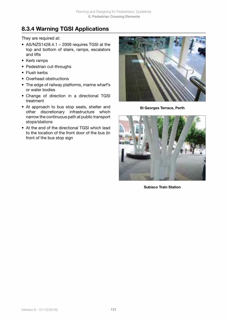
(Version 6 - 01/12/2016)
Planning and Designing for Pedestrians: Guidelines
121
8. Pedestrian Crossing Elements
8.3.4 Warning TGSI Applications
They are required at:
• AS/NZS1428.4.1–2009requiresTGSIatthetop and bottom of stairs, ramps, escalatorsand lifts
• Kerbramps• Pedestriancut-throughs• Flushkerbs• Overheadobstructions• Theedgeofrailwayplatforms,marinewharf’s
or water bodies• Change of direction in a directional TGSI
treatment• At approach to bus stop seats, shelter and
other discretionary infrastructure whichnarrow the continuous path at public transport stops/stations
• AttheendofthedirectionalTGSIwhichleadto the location of the front door of the bus (infront of the bus stop sign
St Georges Terrace, Perth
Subiaco Train Station
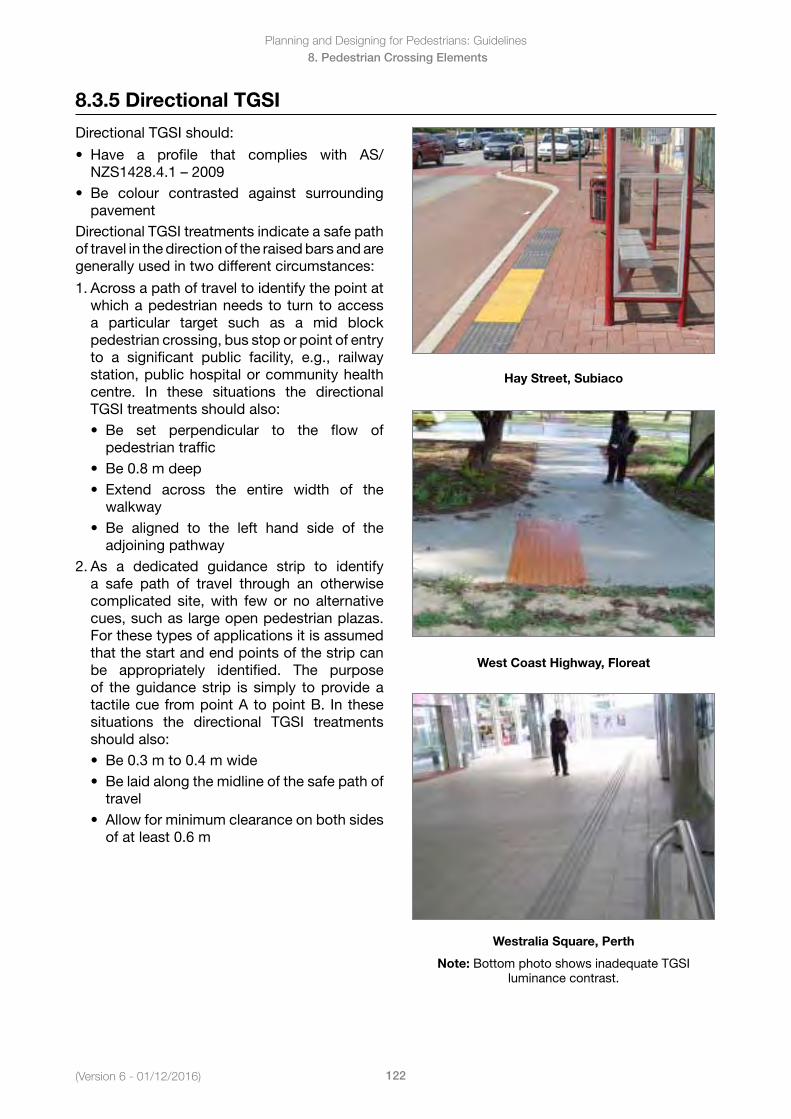
Planning and Designing for Pedestrians: Guidelines
122(Version 6 - 01/12/2016)
8. Pedestrian Crossing Elements
8.3.5 Directional TGSI
Directional TGSI should:
• Have a profile that complies with AS/NZS1428.4.1–2009
• Be colour contrasted against surroundingpavement
Directional TGSI treatments indicate a safe path of travel in the direction of the raised bars and are generally used in two different circumstances:
1. Across a path of travel to identify the point atwhich a pedestrian needs to turn to accessa particular target such as a mid blockpedestrian crossing, bus stop or point of entryto a significant public facility, e.g., railwaystation, public hospital or community healthcentre. In these situations the directionalTGSI treatments should also:• Be set perpendicular to the flow of
pedestrian traffic• Be0.8mdeep• Extend across the entire width of the
walkway• Be aligned to the left hand side of the
adjoining pathway2. As a dedicated guidance strip to identify
a safe path of travel through an otherwisecomplicated site, with few or no alternativecues, such as large open pedestrian plazas.For these types of applications it is assumedthat the start and end points of the strip canbe appropriately identified. The purposeof the guidance strip is simply to provide atactile cue from point A to point B. In thesesituations the directional TGSI treatmentsshould also:• Be0.3mto0.4mwide• Belaidalongthemidlineofthesafepathof
travel• Allowforminimumclearanceonbothsides
of at least 0.6 m
Hay Street, Subiaco
West Coast Highway, Floreat
Westralia Square, Perth
Note: Bottom photo shows inadequate TGSI luminance contrast.
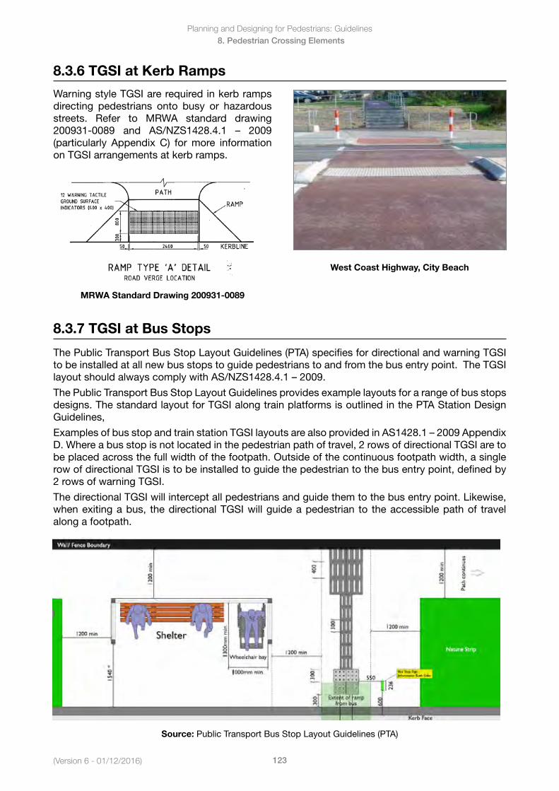
(Version 6 - 01/12/2016)
Planning and Designing for Pedestrians: Guidelines
123
8. Pedestrian Crossing Elements
8.3.6 TGSI at Kerb Ramps
Warning style TGSI are required in kerb ramps directing pedestrians onto busy or hazardous streets. Refer to MRWA standard drawing 200931-0089 and AS/NZS1428.4.1 – 2009(particularly Appendix C) for more information on TGSI arrangements at kerb ramps.
MRWA Standard Drawing 200931-0089
West Coast Highway, City Beach
8.3.7 TGSI at Bus Stops
The Public Transport Bus Stop Layout Guidelines (PTA) specifies for directional and warning TGSI to be installed at all new bus stops to guide pedestrians to and from the bus entry point. The TGSI layoutshouldalwayscomplywithAS/NZS1428.4.1–2009.
The Public Transport Bus Stop Layout Guidelines provides example layouts for a range of bus stops designs. The standard layout for TGSI along train platforms is outlined in the PTA Station Design Guidelines,
ExamplesofbusstopandtrainstationTGSIlayoutsarealsoprovidedinAS1428.1–2009AppendixD. Where a bus stop is not located in the pedestrian path of travel, 2 rows of directional TGSI are to be placed across the full width of the footpath. Outside of the continuous footpath width, a single row of directional TGSI is to be installed to guide the pedestrian to the bus entry point, defined by 2 rows of warning TGSI.
The directional TGSI will intercept all pedestrians and guide them to the bus entry point. Likewise, when exiting a bus, the directional TGSI will guide a pedestrian to the accessible path of travel along a footpath.
Source: Public Transport Bus Stop Layout Guidelines (PTA)
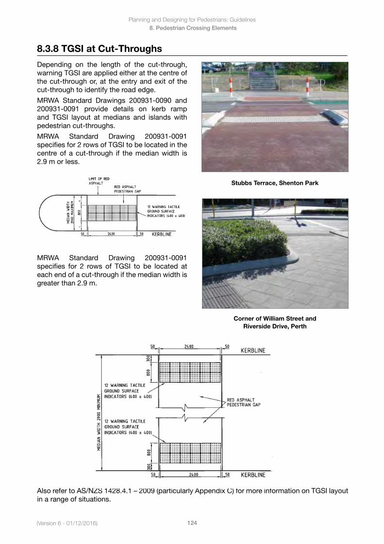
Planning and Designing for Pedestrians: Guidelines
124(Version 6 - 01/12/2016)
8. Pedestrian Crossing Elements
8.3.8 TGSI at Cut-Throughs
Depending on the length of the cut-through, warning TGSI are applied either at the centre of the cut-through or, at the entry and exit of the cut-through to identify the road edge.
MRWA Standard Drawings 200931-0090 and 200931-0091 provide details on kerb ramp and TGSI layout at medians and islands with pedestrian cut-throughs.
MRWA Standard Drawing 200931-0091 specifies for 2 rows of TGSI to be located in the centre of a cut-through if the median width is 2.9 m or less.
MRWA Standard Drawing 200931-0091 specifies for 2 rows of TGSI to be located at each end of a cut-through if the median width is greater than 2.9 m.
Stubbs Terrace, Shenton Park
Corner of William Street and Riverside Drive, Perth
AlsorefertoAS/NZS1428.4.1–2009(particularlyAppendixC)formoreinformationonTGSIlayoutin a range of situations.
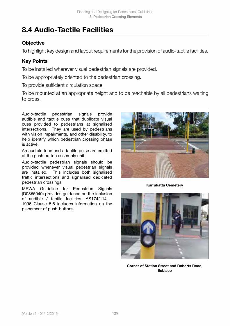
(Version 6 - 01/12/2016)
Planning and Designing for Pedestrians: Guidelines
125
8. Pedestrian Crossing Elements
8.4 Audio-Tactile Facilities
Objective
To highlight key design and layout requirements for the provision of audio-tactile facilities.
Key Points
To be installed wherever visual pedestrian signals are provided.
To be appropriately oriented to the pedestrian crossing.
To provide sufficient circulation space.
To be mounted at an appropriate height and to be reachable by all pedestrians waiting to cross.
Audio-tactile pedestrian signals provide audible and tactile cues that duplicate visual cues provided to pedestrians at signalised intersections. They are used by pedestrians with vision impairments, and other disability, to help identify which pedestrian crossing phase is active.
An audible tone and a tactile pulse are emitted at the push button assembly unit.
Audio-tactile pedestrian signals should be provided whenever visual pedestrian signals are installed. This includes both signalised traffic intersections and signalised dedicated pedestrian crossings.
MRWA Guideline for Pedestrian Signals (D08#6040) provides guidance on the inclusion of audible / tactile facilities. AS1742.14 –1996 Clause 5.6 includes information on the placement of push-buttons.
Karrakatta Cemetery
Corner of Station Street and Roberts Road, Subiaco
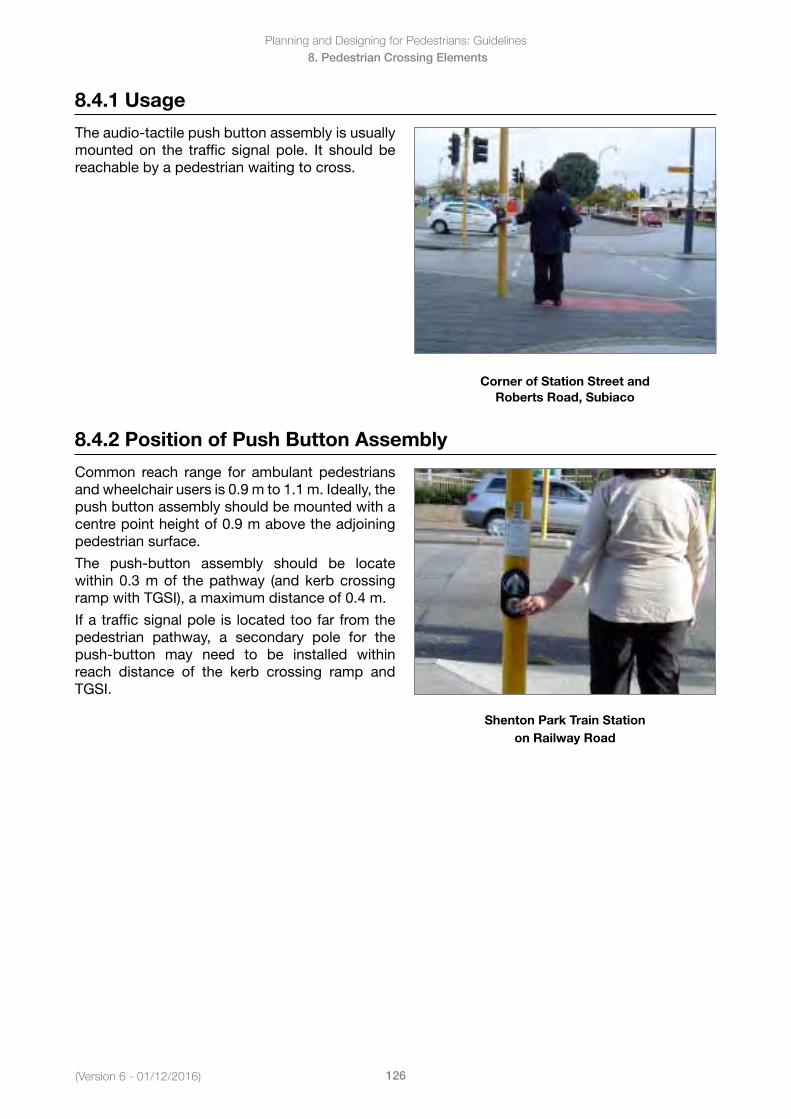
Planning and Designing for Pedestrians: Guidelines
126(Version 6 - 01/12/2016)
8. Pedestrian Crossing Elements
8.4.1 Usage
The audio-tactile push button assembly is usually mounted on the traffic signal pole. It should be reachable by a pedestrian waiting to cross.
Corner of Station Street and Roberts Road, Subiaco
8.4.2 Position of Push Button Assembly
Common reach range for ambulant pedestrians and wheelchair users is 0.9 m to 1.1 m. Ideally, the push button assembly should be mounted with a centre point height of 0.9 m above the adjoining pedestrian surface.
The push-button assembly should be locate within 0.3 m of the pathway (and kerb crossing ramp with TGSI), a maximum distance of 0.4 m.
If a traffic signal pole is located too far from the pedestrian pathway, a secondary pole for the push-button may need to be installed within reach distance of the kerb crossing ramp and TGSI.
Shenton Park Train Station on Railway Road
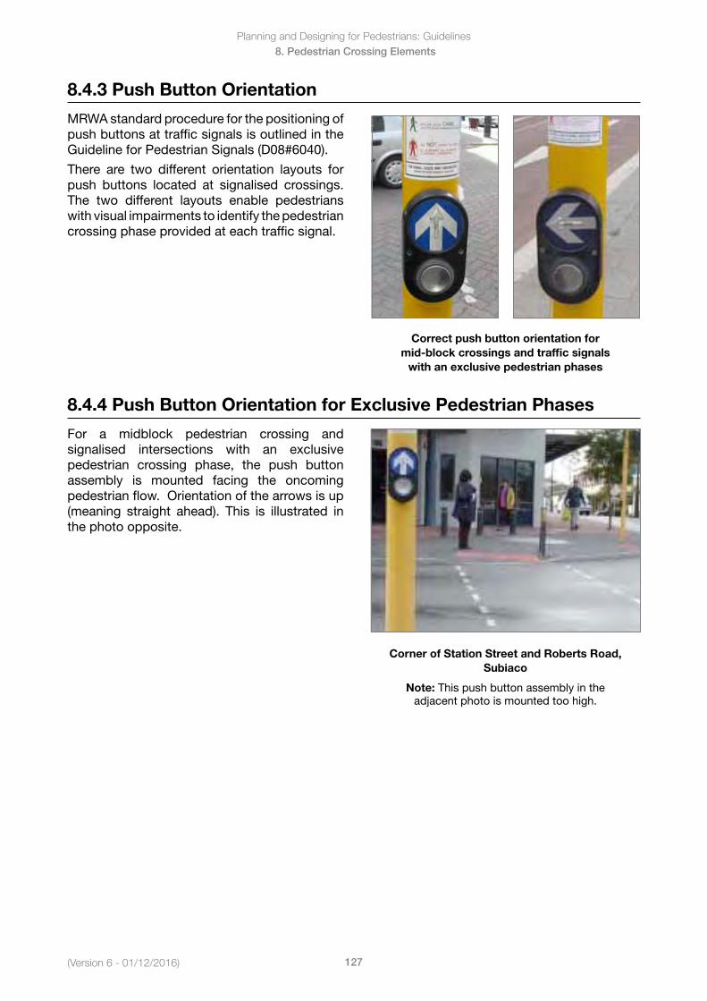
(Version 6 - 01/12/2016)
Planning and Designing for Pedestrians: Guidelines
127
8. Pedestrian Crossing Elements
8.4.3 Push Button Orientation
MRWA standard procedure for the positioning of push buttons at traffic signals is outlined in the Guideline for Pedestrian Signals (D08#6040).
There are two different orientation layouts for push buttons located at signalised crossings. The two different layouts enable pedestrians with visual impairments to identify the pedestrian crossing phase provided at each traffic signal.
Correct push button orientation for mid-block crossings and traffic signals
with an exclusive pedestrian phases
8.4.4 Push Button Orientation for Exclusive Pedestrian Phases
For a midblock pedestrian crossing and signalised intersections with an exclusive pedestrian crossing phase, the push button assembly is mounted facing the oncoming pedestrian flow. Orientation of the arrows is up (meaning straight ahead). This is illustrated in the photo opposite.
Corner of Station Street and Roberts Road, Subiaco
Note: This push button assembly in the adjacent photo is mounted too high.
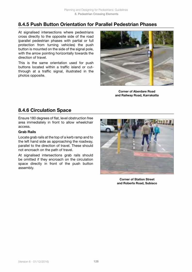
Planning and Designing for Pedestrians: Guidelines
128(Version 6 - 01/12/2016)
8. Pedestrian Crossing Elements
8.4.5 Push Button Orientation for Parallel Pedestrian Phases
At signalised intersections where pedestrians cross directly to the opposite side of the road (parallel pedestrian phases with partial or full protection from turning vehicles) the push button is mounted on the side of the signal pole, with the arrow pointing horizontally towards the direction of travel.
This is the same orientation used for push buttons located within a traffic island or cut-through at a traffic signal, illustrated in the photos opposite.
Corner of Aberdare Road and Railway Road, Karrakatta
8.4.6 Circulation Space
Ensure 180 degrees of flat, level obstruction free area immediately in front to allow wheelchair access.
Grab Rails
Locate grab rails at the top of a kerb ramp and to the left hand side as approaching the roadway, parallel to the direction of travel. These should not encroach on the path of travel.
At signalised intersections grab rails should be omitted if they encroach on the circulation space directly in front of the push button assembly.
Corner of Station Street and Roberts Road, Subiaco
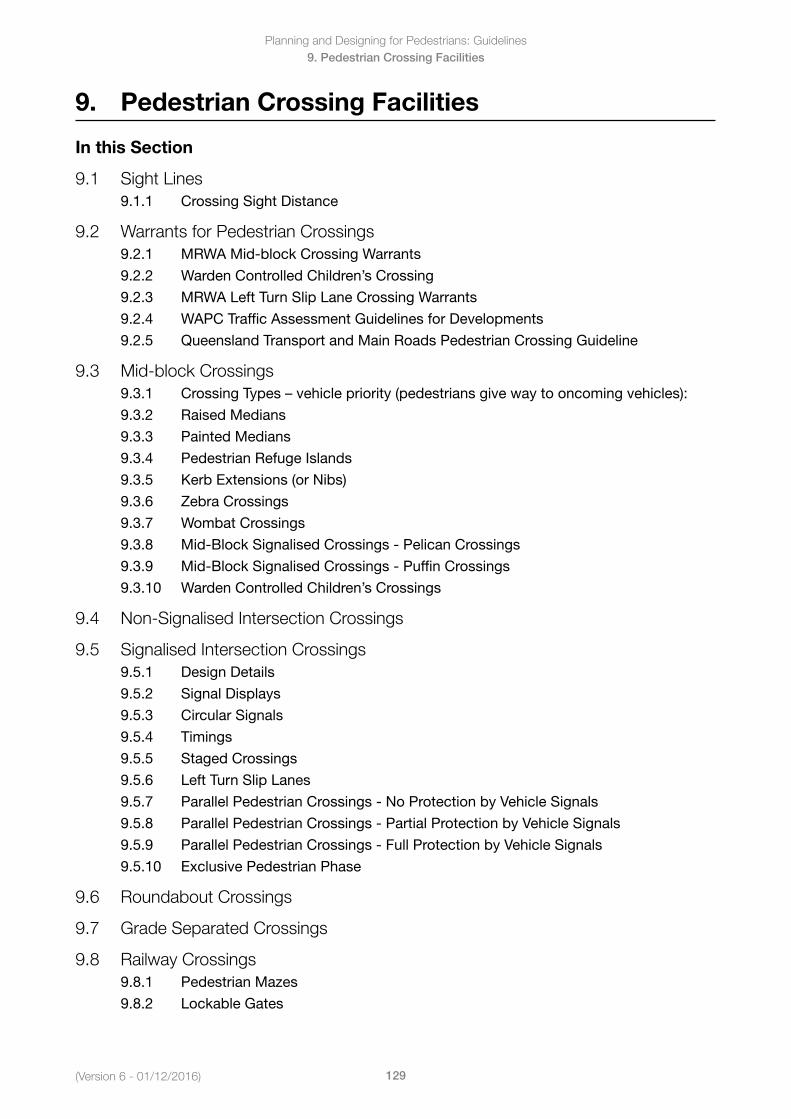
Planning and Designing for Pedestrians: Guidelines
129(Version 6 - 01/12/2016)
9. Pedestrian Crossing Facilities
9. Pedestrian Crossing Facilities
In this Section
9.1 Sight Lines9.1.1 Crossing Sight Distance
9.2 Warrants for Pedestrian Crossings9.2.1 MRWA Mid-block Crossing Warrants
9.2.2 Warden Controlled Children’s Crossing
9.2.3 MRWA Left Turn Slip Lane Crossing Warrants
9.2.4 WAPC Traffic Assessment Guidelines for Developments
9.2.5 Queensland Transport and Main Roads Pedestrian Crossing Guideline
9.3 Mid-block Crossings9.3.1 CrossingTypes–vehiclepriority(pedestriansgivewaytooncomingvehicles):
9.3.2 Raised Medians
9.3.3 Painted Medians
9.3.4 Pedestrian Refuge Islands
9.3.5 Kerb Extensions (or Nibs)
9.3.6 Zebra Crossings
9.3.7 Wombat Crossings
9.3.8 Mid-Block Signalised Crossings - Pelican Crossings
9.3.9 Mid-Block Signalised Crossings - Puffin Crossings
9.3.10 Warden Controlled Children’s Crossings
9.4 Non-Signalised Intersection Crossings
9.5 Signalised Intersection Crossings9.5.1 Design Details
9.5.2 Signal Displays
9.5.3 Circular Signals
9.5.4 Timings
9.5.5 Staged Crossings
9.5.6 Left Turn Slip Lanes
9.5.7 Parallel Pedestrian Crossings - No Protection by Vehicle Signals
9.5.8 Parallel Pedestrian Crossings - Partial Protection by Vehicle Signals
9.5.9 Parallel Pedestrian Crossings - Full Protection by Vehicle Signals
9.5.10 Exclusive Pedestrian Phase
9.6 Roundabout Crossings
9.7 Grade Separated Crossings
9.8 Railway Crossings9.8.1 Pedestrian Mazes
9.8.2 Lockable Gates
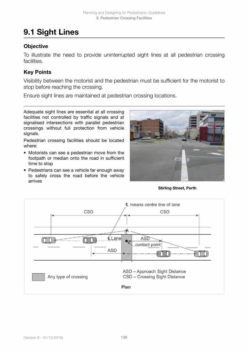
(Version 6 - 01/12/2016)
Planning and Designing for Pedestrians: Guidelines
130
9. Pedestrian Crossing Facilities
9.1 Sight Lines
Objective
To illustrate the need to provide uninterrupted sight lines at all pedestrian crossing facilities.
Key Points
Visibility between the motorist and the pedestrian must be sufficient for the motorist to stop before reaching the crossing.
Ensure sight lines are maintained at pedestrian crossing locations.
Adequate sight lines are essential at all crossing facilities not controlled by traffic signals and at signalised intersections with parallel pedestrian crossings without full protection from vehicle signals.
Pedestrian crossing facilities should be located where:
• Motoristscanseeapedestrianmovefromthefootpath or median onto the road in sufficienttime to stop
• Pedestrianscanseeavehiclefarenoughawayto safely cross the road before the vehiclearrives
Stirling Street, Perth
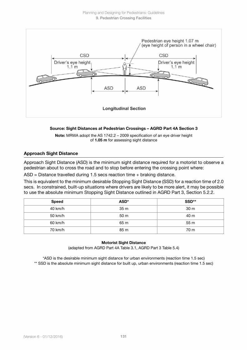
Planning and Designing for Pedestrians: Guidelines
131(Version 6 - 01/12/2016)
9. Pedestrian Crossing Facilities
Source: Sight Distances at Pedestrian Crossings – AGRD Part 4A Section 3
Note: MRWAadopttheAS1742.2–2009specificationofaneyedriverheight of 1.05 m for assessing sight distance
Approach Sight Distance
Approach Sight Distance (ASD) is the minimum sight distance required for a motorist to observe a pedestrian about to cross the road and to stop before entering the crossing point where:
ASD = Distance travelled during 1.5 secs reaction time + braking distance.
This is equivalent to the minimum desirable Stopping Sight Distance (SSD) for a reaction time of 2.0 secs. In constrained, built-up situations where drivers are likely to be more alert, it may be possible to use the absolute minimum Stopping Sight Distance outlined in AGRD Part 3, Section 5.2.2.
Speed ASD* SSD**
40 km/h 35 m 30 m
50 km/h 50 m 40 m
60 km/h 65 m 55 m
70 km/h 85 m 70 m
Motorist Sight Distance(adapted from AGRD Part 4A Table 3.1, AGRD Part 3 Table 5.4)
*ASD is the desirable minimum sight distance for urban environments (reaction time 1.5 sec)** SSD is the absolute minimum sight distance for built up, urban environments (reaction time 1.5 sec)
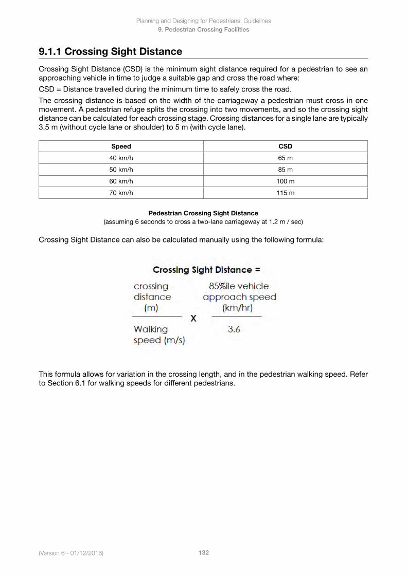
(Version 6 - 01/12/2016)
Planning and Designing for Pedestrians: Guidelines
132
9. Pedestrian Crossing Facilities
9.1.1 Crossing Sight Distance
Crossing Sight Distance (CSD) is the minimum sight distance required for a pedestrian to see an approaching vehicle in time to judge a suitable gap and cross the road where:
CSD = Distance travelled during the minimum time to safely cross the road.
The crossing distance is based on the width of the carriageway a pedestrian must cross in one movement. A pedestrian refuge splits the crossing into two movements, and so the crossing sight distance can be calculated for each crossing stage. Crossing distances for a single lane are typically 3.5 m (without cycle lane or shoulder) to 5 m (with cycle lane).
Speed CSD
40 km/h 65 m
50 km/h 85 m
60 km/h 100 m
70 km/h 115 m
Pedestrian Crossing Sight Distance(assuming 6 seconds to cross a two-lane carriageway at 1.2 m / sec)
Crossing Sight Distance can also be calculated manually using the following formula:
This formula allows for variation in the crossing length, and in the pedestrian walking speed. Refer to Section 6.1 for walking speeds for different pedestrians.
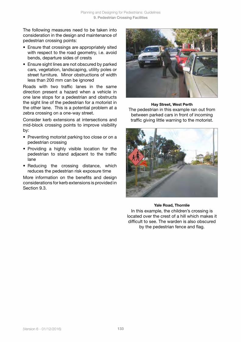
Planning and Designing for Pedestrians: Guidelines
133(Version 6 - 01/12/2016)
9. Pedestrian Crossing Facilities
The following measures need to be taken into consideration in the design and maintenance of pedestrian crossing points:
• Ensurethatcrossingsareappropriatelysitedwith respect to the road geometry, i.e. avoidbends, departure sides of crests
• Ensuresightlinesarenotobscuredbyparkedcars, vegetation, landscaping, utility poles orstreet furniture. Minor obstructions of widthless than 200 mm can be ignored
Roads with two traffic lanes in the same direction present a hazard when a vehicle in one lane stops for a pedestrian and obstructs the sight line of the pedestrian for a motorist in the other lane. This is a potential problem at a zebra crossing on a one-way street.
Consider kerb extensions at intersections and mid-block crossing points to improve visibility by:
• Preventingmotoristparkingtoocloseoronapedestrian crossing
• Providing a highly visible location for thepedestrian to stand adjacent to the trafficlane
• Reducing the crossing distance, whichreduces the pedestrian risk exposure time
More information on the benefits and design considerations for kerb extensions is provided in Section 9.3.
Hay Street, West PerthThe pedestrian in this example ran out from between parked cars in front of incoming traffic giving little warning to the motorist.
Yale Road, Thornlie
In this example, the children’s crossing is located over the crest of a hill which makes it difficult to see. The warden is also obscured
by the pedestrian fence and flag.
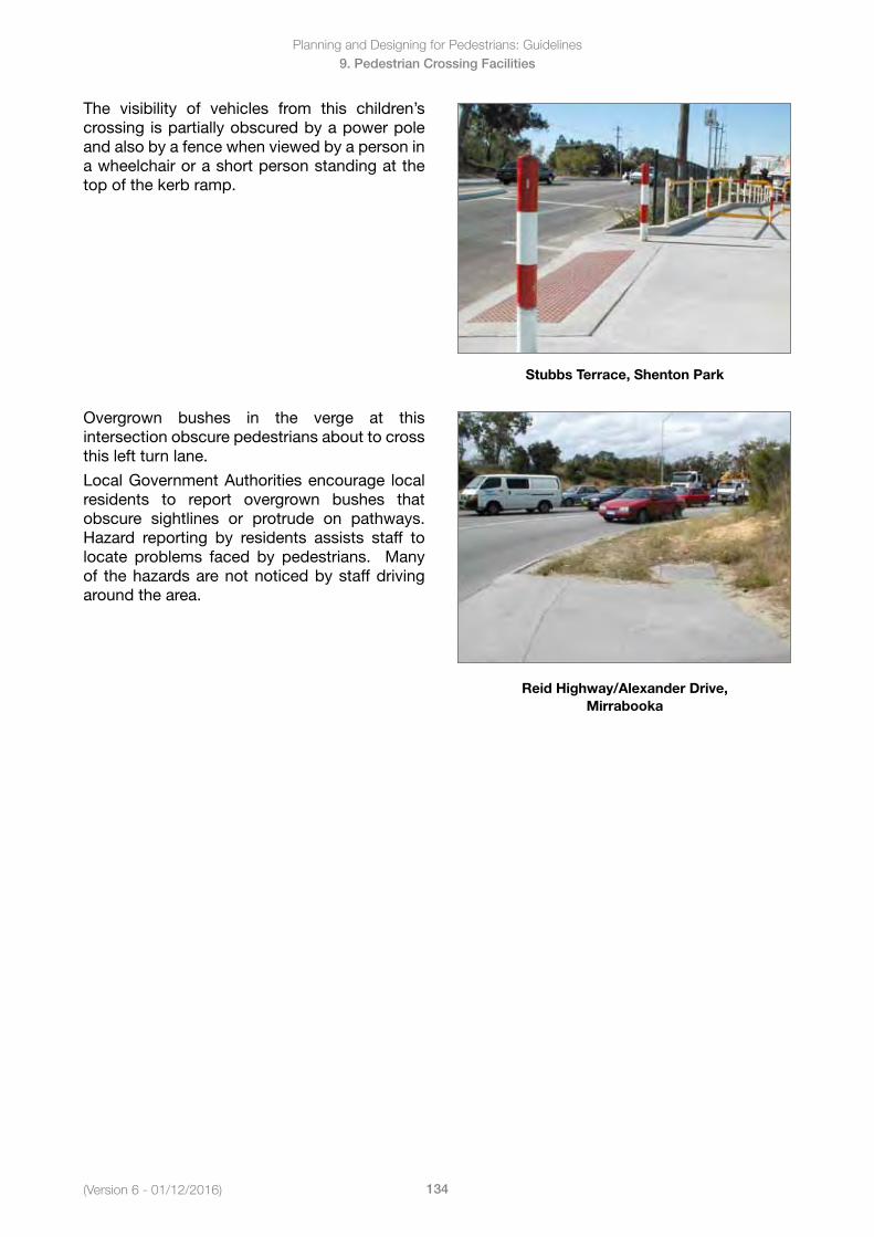
(Version 6 - 01/12/2016)
Planning and Designing for Pedestrians: Guidelines
134
9. Pedestrian Crossing Facilities
The visibility of vehicles from this children’s crossing is partially obscured by a power pole and also by a fence when viewed by a person in a wheelchair or a short person standing at the top of the kerb ramp.
Stubbs Terrace, Shenton Park
Overgrown bushes in the verge at this intersection obscure pedestrians about to cross this left turn lane.
Local Government Authorities encourage local residents to report overgrown bushes that obscure sightlines or protrude on pathways. Hazard reporting by residents assists staff tolocate problems faced by pedestrians. Many of the hazards are not noticed by staff driving around the area.
Reid Highway/Alexander Drive, Mirrabooka
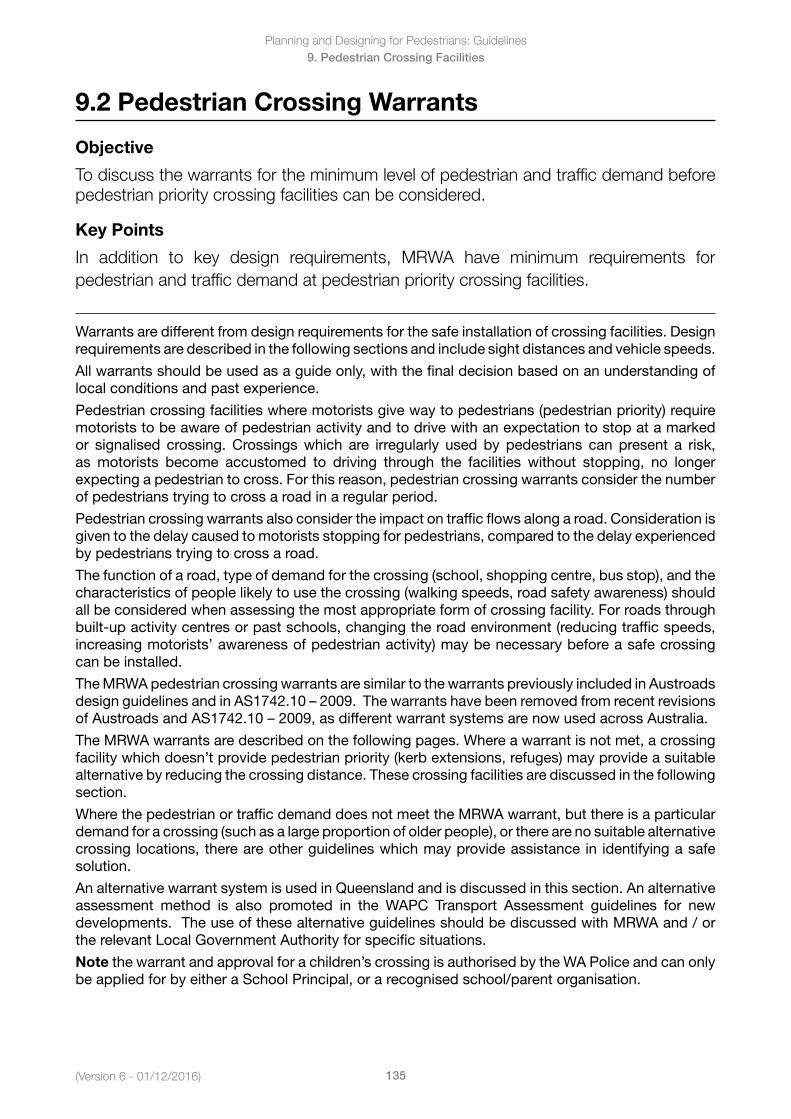
Planning and Designing for Pedestrians: Guidelines
135(Version 6 - 01/12/2016)
9. Pedestrian Crossing Facilities
9.2 Pedestrian Crossing Warrants
Objective
To discuss the warrants for the minimum level of pedestrian and traffic demand before pedestrian priority crossing facilities can be considered.
Key Points
In addition to key design requirements, MRWA have minimum requirements for pedestrian and traffic demand at pedestrian priority crossing facilities.
Warrants are different from design requirements for the safe installation of crossing facilities. Design requirements are described in the following sections and include sight distances and vehicle speeds.
All warrants should be used as a guide only, with the final decision based on an understanding of local conditions and past experience.
Pedestrian crossing facilities where motorists give way to pedestrians (pedestrian priority) require motorists to be aware of pedestrian activity and to drive with an expectation to stop at a marked or signalised crossing. Crossings which are irregularly used by pedestrians can present a risk, as motorists become accustomed to driving through the facilities without stopping, no longer expecting a pedestrian to cross. For this reason, pedestrian crossing warrants consider the number of pedestrians trying to cross a road in a regular period.
Pedestrian crossing warrants also consider the impact on traffic flows along a road. Consideration is given to the delay caused to motorists stopping for pedestrians, compared to the delay experienced by pedestrians trying to cross a road.
The function of a road, type of demand for the crossing (school, shopping centre, bus stop), and the characteristics of people likely to use the crossing (walking speeds, road safety awareness) should all be considered when assessing the most appropriate form of crossing facility. For roads through built-up activity centres or past schools, changing the road environment (reducing traffic speeds, increasing motorists’ awareness of pedestrian activity) may be necessary before a safe crossing can be installed.
The MRWA pedestrian crossing warrants are similar to the warrants previously included in Austroads designguidelinesandinAS1742.10–2009.ThewarrantshavebeenremovedfromrecentrevisionsofAustroadsandAS1742.10–2009,asdifferentwarrantsystemsarenowusedacrossAustralia.
The MRWA warrants are described on the following pages. Where a warrant is not met, a crossing facility which doesn’t provide pedestrian priority (kerb extensions, refuges) may provide a suitable alternative by reducing the crossing distance. These crossing facilities are discussed in the following section.
Where the pedestrian or traffic demand does not meet the MRWA warrant, but there is a particular demand for a crossing (such as a large proportion of older people), or there are no suitable alternative crossing locations, there are other guidelines which may provide assistance in identifying a safe solution.
An alternative warrant system is used in Queensland and is discussed in this section. An alternative assessment method is also promoted in the WAPC Transport Assessment guidelines for new developments. The use of these alternative guidelines should be discussed with MRWA and / or the relevant Local Government Authority for specific situations.
Note the warrant and approval for a children’s crossing is authorised by the WA Police and can only be applied for by either a School Principal, or a recognised school/parent organisation.
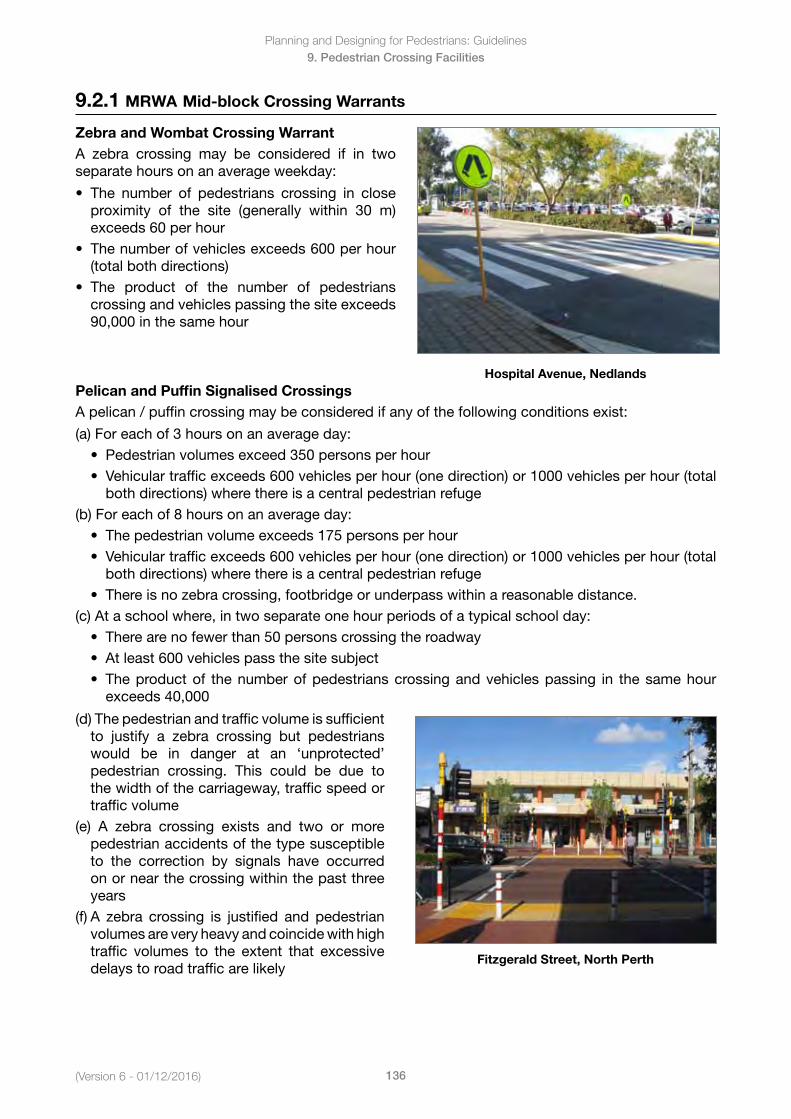
(Version 6 - 01/12/2016)
Planning and Designing for Pedestrians: Guidelines
136
9. Pedestrian Crossing Facilities
9.2.1 MRWA Mid-block Crossing Warrants
Zebra and Wombat Crossing WarrantA zebra crossing may be considered if in two separate hours on an average weekday:
• The number of pedestrians crossing in closeproximity of the site (generally within 30 m)exceeds 60 per hour
• Thenumberofvehiclesexceeds600perhour(total both directions)
• The product of the number of pedestrianscrossing and vehicles passing the site exceeds90,000 in the same hour
Hospital Avenue, NedlandsPelican and Puffin Signalised CrossingsA pelican / puffin crossing may be considered if any of the following conditions exist:
(a) For each of 3 hours on an average day:• Pedestrianvolumesexceed350personsperhour• Vehiculartrafficexceeds600vehiclesperhour(onedirection)or1000vehiclesperhour(total
both directions) where there is a central pedestrian refuge(b) For each of 8 hours on an average day:
• Thepedestrianvolumeexceeds175personsperhour• Vehiculartrafficexceeds600vehiclesperhour(onedirection)or1000vehiclesperhour(total
both directions) where there is a central pedestrian refuge• Thereisnozebracrossing,footbridgeorunderpasswithinareasonabledistance.
(c) At a school where, in two separate one hour periods of a typical school day:• Therearenofewerthan50personscrossingtheroadway• Atleast600vehiclespassthesitesubject• Theproductof thenumberofpedestrianscrossingandvehiclespassing in thesamehour
exceeds 40,000
(d) The pedestrian and traffic volume is sufficient to justify a zebra crossing but pedestrians would be in danger at an ‘unprotected’ pedestrian crossing. This could be due to the width of the carriageway, traffic speed or traffic volume
(e) A zebra crossing exists and two or more pedestrian accidents of the type susceptible to the correction by signals have occurred on or near the crossing within the past three years
(f) A zebra crossing is justified and pedestrian volumes are very heavy and coincide with high traffic volumes to the extent that excessive delays to road traffic are likely
Fitzgerald Street, North Perth
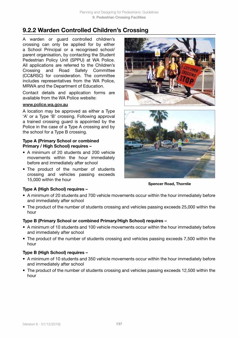
Planning and Designing for Pedestrians: Guidelines
137(Version 6 - 01/12/2016)
9. Pedestrian Crossing Facilities
A warden or guard controlled children’s crossing can only be applied for by either a School Principal or a recognised school/parent organisation, by contacting the Student Pedestrian Policy Unit (SPPU) at WA Police. All applications are referred to the Children’s Crossing and Road Safety Committee (CC&RSC) for consideration. The committee includes representatives from the WA Police, MRWA and the Department of Education.
Contact details and application forms are available from the WA Police website:
www.police.wa.gov.au
A location may be approved as either a Type ‘A’ or a Type ‘B’ crossing. Following approval a trained crossing guard is appointed by the Police in the case of a Type A crossing and by the school for a Type B crossing.
Type A (Primary School or combined Primary / High School) requires – • Aminimumof20studentsand200vehicle
movements within the hour immediatelybefore and immediately after school
• The product of the number of studentscrossing and vehicles passing exceeds15,000 within the hour
Spencer Road, ThornlieType A (High School) requires – • Aminimumof20studentsand700vehiclemovementsoccurwithinthehourimmediatelybefore
and immediately after school• Theproductofthenumberofstudentscrossingandvehiclespassingexceeds25,000withinthe
hour
Type B (Primary School or combined Primary/High School) requires – • Aminimumof10studentsand100vehiclemovementsoccurwithinthehourimmediatelybefore
and immediately after school• Theproductofthenumberofstudentscrossingandvehiclespassingexceeds7,500withinthe
hour
Type B (High School) requires – • Aminimumof10studentsand350vehiclemovementsoccurwithinthehourimmediatelybefore
and immediately after school• Theproductofthenumberofstudentscrossingandvehiclespassingexceeds12,500withinthe
hour
9.2.2 Warden Controlled Children’s Crossing
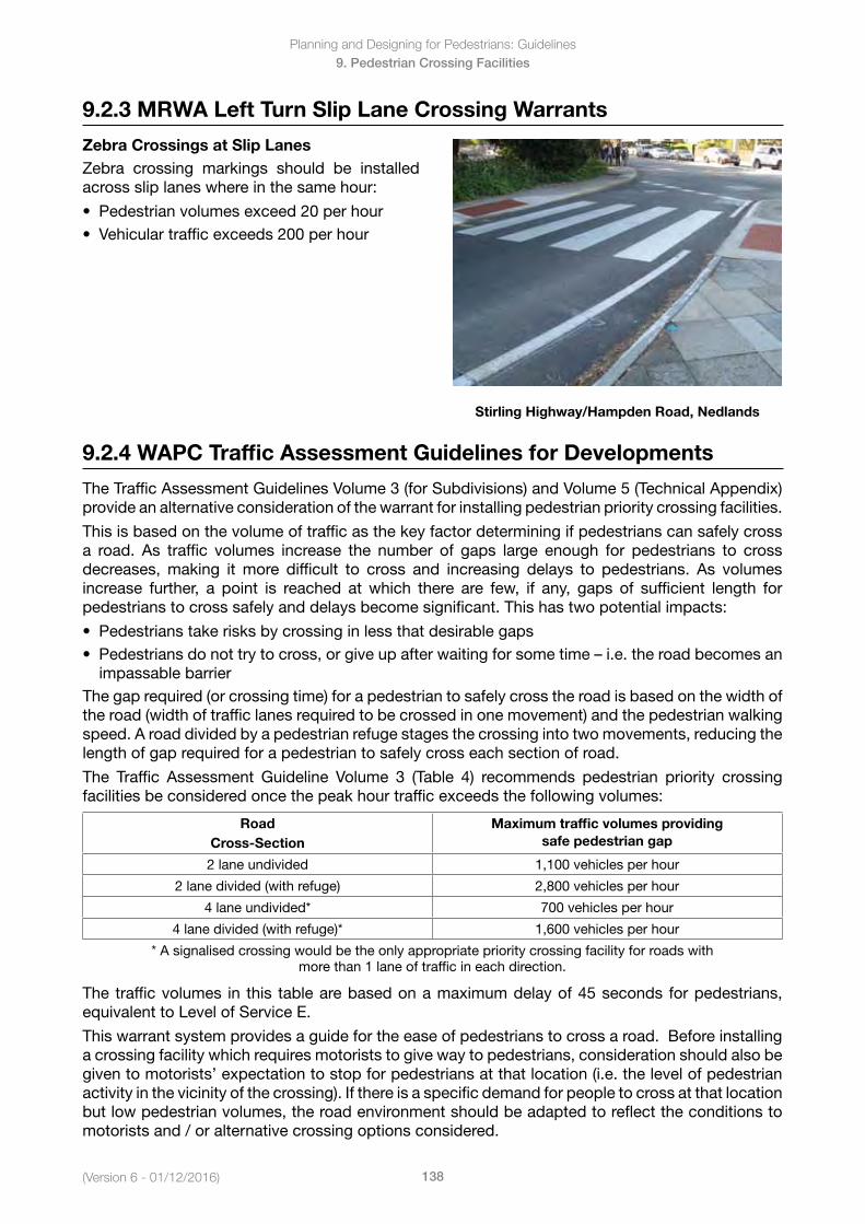
(Version 6 - 01/12/2016)
Planning and Designing for Pedestrians: Guidelines
138
9. Pedestrian Crossing Facilities
9.2.3 MRWA Left Turn Slip Lane Crossing Warrants
Zebra Crossings at Slip LanesZebra crossing markings should be installed across slip lanes where in the same hour:
• Pedestrianvolumesexceed20perhour• Vehiculartrafficexceeds200perhour
Stirling Highway/Hampden Road, Nedlands
9.2.4 WAPC Traffic Assessment Guidelines for Developments
The Traffic Assessment Guidelines Volume 3 (for Subdivisions) and Volume 5 (Technical Appendix) provide an alternative consideration of the warrant for installing pedestrian priority crossing facilities.
This is based on the volume of traffic as the key factor determining if pedestrians can safely cross a road. As traffic volumes increase the number of gaps large enough for pedestrians to cross decreases, making it more difficult to cross and increasing delays to pedestrians. As volumes increase further, a point is reached at which there are few, if any, gaps of sufficient length for pedestrians to cross safely and delays become significant. This has two potential impacts:
• Pedestrianstakerisksbycrossinginlessthatdesirablegaps• Pedestriansdonottrytocross,orgiveupafterwaitingforsometime–i.e.theroadbecomesan
impassable barrierThe gap required (or crossing time) for a pedestrian to safely cross the road is based on the width of the road (width of traffic lanes required to be crossed in one movement) and the pedestrian walking speed. A road divided by a pedestrian refuge stages the crossing into two movements, reducing the length of gap required for a pedestrian to safely cross each section of road.
The Traffic Assessment Guideline Volume 3 (Table 4) recommends pedestrian priority crossing facilities be considered once the peak hour traffic exceeds the following volumes:
Road Cross-Section
Maximum traffic volumes providing safe pedestrian gap
2 lane undivided 1,100 vehicles per hour
2 lane divided (with refuge) 2,800 vehicles per hour
4 lane undivided* 700 vehicles per hour
4 lane divided (with refuge)* 1,600 vehicles per hour
* A signalised crossing would be the only appropriate priority crossing facility for roads withmore than 1 lane of traffic in each direction.
The traffic volumes in this table are based on a maximum delay of 45 seconds for pedestrians, equivalent to Level of Service E.
This warrant system provides a guide for the ease of pedestrians to cross a road. Before installing a crossing facility which requires motorists to give way to pedestrians, consideration should also be given to motorists’ expectation to stop for pedestrians at that location (i.e. the level of pedestrian activity in the vicinity of the crossing). If there is a specific demand for people to cross at that location but low pedestrian volumes, the road environment should be adapted to reflect the conditions to motorists and / or alternative crossing options considered.
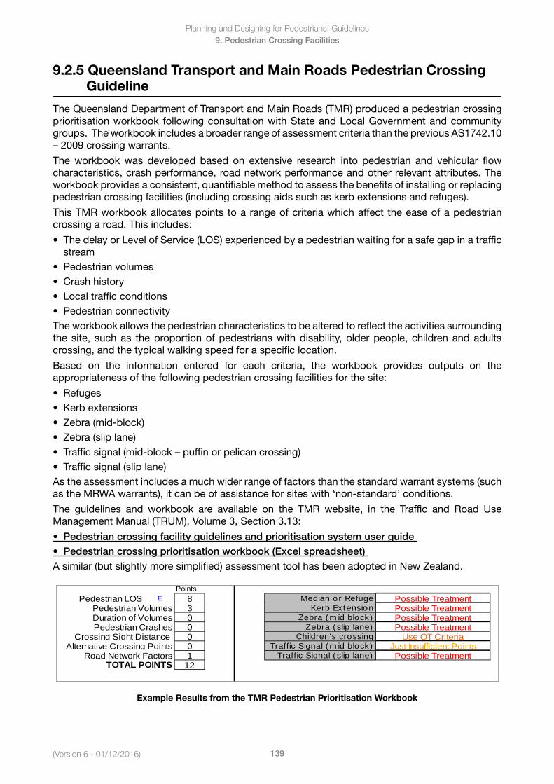
Planning and Designing for Pedestrians: Guidelines
139(Version 6 - 01/12/2016)
9. Pedestrian Crossing Facilities
9.2.5 Queensland Transport and Main Roads Pedestrian Crossing Guideline
The Queensland Department of Transport and Main Roads (TMR) produced a pedestrian crossing prioritisation workbook following consultation with State and Local Government and community groups. The workbook includes a broader range of assessment criteria than the previous AS1742.10 – 2009crossingwarrants.
The workbook was developed based on extensive research into pedestrian and vehicular flow characteristics, crash performance, road network performance and other relevant attributes. The workbook provides a consistent, quantifiable method to assess the benefits of installing or replacing pedestrian crossing facilities (including crossing aids such as kerb extensions and refuges).
This TMR workbook allocates points to a range of criteria which affect the ease of a pedestrian crossing a road. This includes:
• ThedelayorLevelofService(LOS)experiencedbyapedestrianwaitingforasafegapinatrafficstream
• Pedestrianvolumes• Crashhistory• Localtrafficconditions• PedestrianconnectivityThe workbook allows the pedestrian characteristics to be altered to reflect the activities surrounding the site, such as the proportion of pedestrians with disability, older people, children and adults crossing, and the typical walking speed for a specific location.
Based on the information entered for each criteria, the workbook provides outputs on the appropriateness of the following pedestrian crossing facilities for the site:
• Refuges• Kerbextensions• Zebra(mid-block)• Zebra(sliplane)• Trafficsignal(mid-block–puffinorpelicancrossing)• Trafficsignal(sliplane)As the assessment includes a much wider range of factors than the standard warrant systems (such as the MRWA warrants), it can be of assistance for sites with ‘non-standard’ conditions.
The guidelines and workbook are available on the TMR website, in the Traffic and Road Use Management Manual (TRUM), Volume 3, Section 3.13:
• Pedestriancrossingfacilityguidelinesandprioritisationsystemuserguide• Pedestriancrossingprioritisationworkbook(Excelspreadsheet)A similar (but slightly more simplified) assessment tool has been adopted in New Zealand.
PointsPedestrian LOS E 8 Median or Refuge Possible Treatment
Pedestrian Volumes 3 Kerb Extension Possible TreatmentDuration of Volumes 0 Zebra (mid block) Possible TreatmentPedestrian Crashes 0 Zebra (slip lane) Possible Treatment
Crossing Sight Distance 0 Children's crossing Use QT CriteriaAlternative Crossing Points 0 Traffic Signal (mid block) Just Insufficient Points
Road Network Factors 1 Traffic Signal (slip lane) Possible TreatmentTOTAL POINTS 12
Example Results from the TMR Pedestrian Prioritisation Workbook
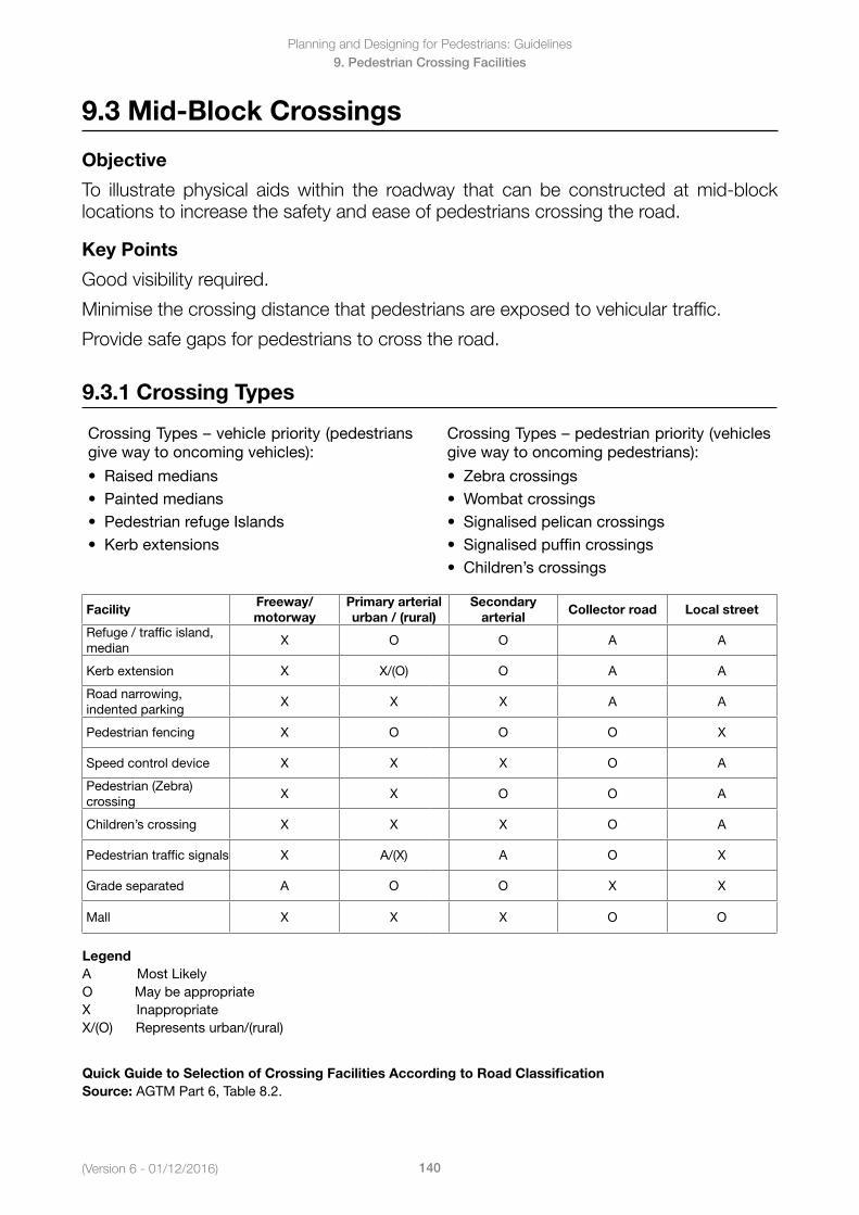
(Version 6 - 01/12/2016)
Planning and Designing for Pedestrians: Guidelines
140
9. Pedestrian Crossing Facilities
9.3 Mid-Block Crossings
Objective
To illustrate physical aids within the roadway that can be constructed at mid-block locations to increase the safety and ease of pedestrians crossing the road.
Key Points
Good visibility required.
Minimise the crossing distance that pedestrians are exposed to vehicular traffic.
Provide safe gaps for pedestrians to cross the road.
9.3.1 Crossing Types
CrossingTypes–vehiclepriority(pedestriansgive way to oncoming vehicles):
• Raisedmedians• Paintedmedians• PedestrianrefugeIslands• Kerbextensions
CrossingTypes–pedestrianpriority(vehiclesgive way to oncoming pedestrians):
• Zebracrossings• Wombatcrossings• Signalisedpelicancrossings• Signalisedpuffincrossings• Children’scrossings
FacilityFreeway/ motorway
Primary arterial urban / (rural)
Secondary arterial
Collector road Local street
Refuge / traffic island, median
X O O A A
Kerb extension X X/(O) O A A
Road narrowing, indented parking
X X X A A
Pedestrian fencing X O O O X
Speed control device X X X O A
Pedestrian (Zebra) crossing
X X O O A
Children’s crossing X X X O A
Pedestrian traffic signals X A/(X) A O X
Grade separated A O O X X
Mall X X X O O
LegendA Most LikelyO May be appropriateX InappropriateX/(O) Represents urban/(rural)
Quick Guide to Selection of Crossing Facilities According to Road ClassificationSource: AGTM Part 6, Table 8.2.
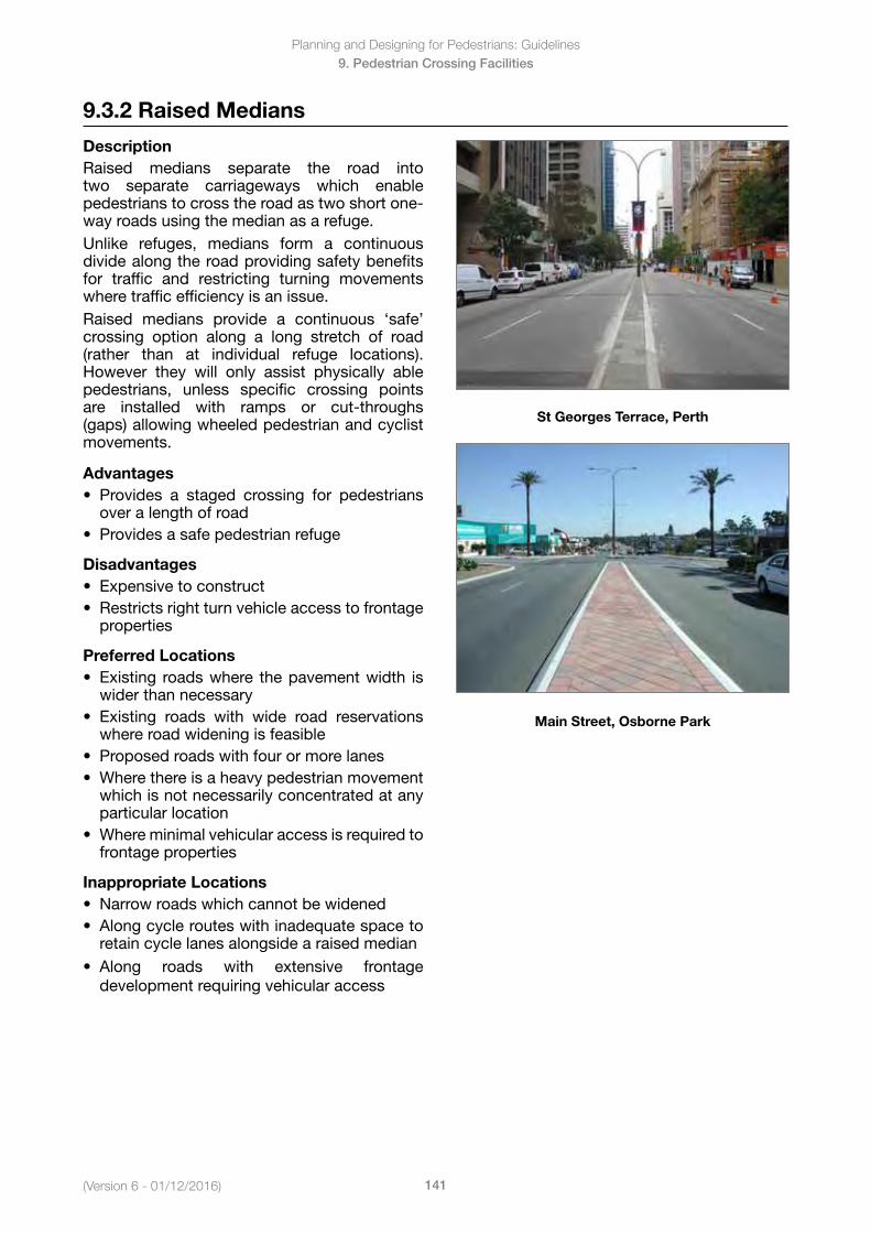
Planning and Designing for Pedestrians: Guidelines
141(Version 6 - 01/12/2016)
9. Pedestrian Crossing Facilities
9.3.2 Raised Medians
DescriptionRaised medians separate the road into two separate carriageways which enable pedestrians to cross the road as two short one-way roads using the median as a refuge. Unlike refuges, medians form a continuous divide along the road providing safety benefits for traffic and restricting turning movements where traffic efficiency is an issue.Raised medians provide a continuous ‘safe’ crossing option along a long stretch of road (rather than at individual refuge locations). However they will only assist physically ablepedestrians, unless specific crossing points are installed with ramps or cut-throughs (gaps) allowing wheeled pedestrian and cyclist movements.
Advantages• Provides a staged crossing for pedestrians
over a length of road• Providesasafepedestrianrefuge
Disadvantages• Expensivetoconstruct• Restrictsrightturnvehicleaccesstofrontage
properties
Preferred Locations• Existing roadswhere thepavementwidth is
wider than necessary• Existing roads with wide road reservations
where road widening is feasible• Proposedroadswithfourormorelanes• Wherethereisaheavypedestrianmovement
which is not necessarily concentrated at anyparticular location
• Whereminimalvehicularaccessisrequiredtofrontage properties
Inappropriate Locations• Narrowroadswhichcannotbewidened• Alongcyclerouteswithinadequatespaceto
retain cycle lanes alongside a raised median• Along roads with extensive frontage
development requiring vehicular access
St Georges Terrace, Perth
Main Street, Osborne Park
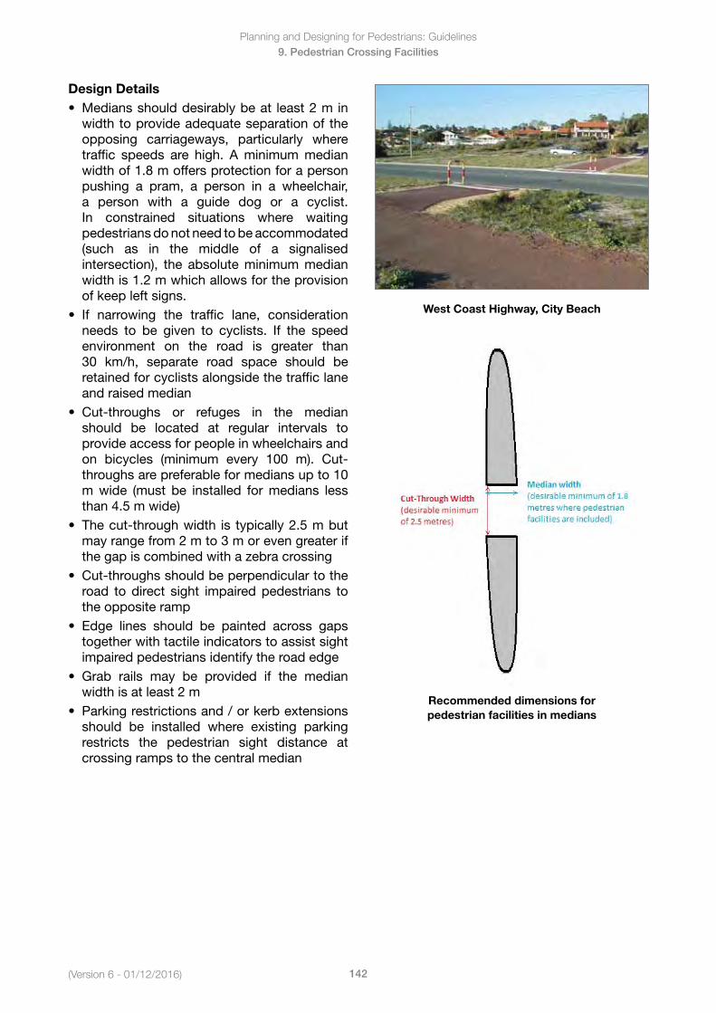
(Version 6 - 01/12/2016)
Planning and Designing for Pedestrians: Guidelines
142
9. Pedestrian Crossing Facilities
Design Details• Mediansshoulddesirablybeat least2min
width to provide adequate separation of theopposing carriageways, particularly wheretraffic speeds are high. A minimum medianwidth of 1.8 m offers protection for a personpushing a pram, a person in a wheelchair,a person with a guide dog or a cyclist.In constrained situations where waitingpedestrians do not need to be accommodated (such as in the middle of a signalisedintersection), the absolute minimum medianwidth is 1.2 m which allows for the provisionof keep left signs.
• If narrowing the traffic lane, considerationneeds to be given to cyclists. If the speedenvironment on the road is greater than30 km/h, separate road space should beretained for cyclists alongside the traffic laneand raised median
• Cut-throughs or refuges in the medianshould be located at regular intervals toprovide access for people in wheelchairs andon bicycles (minimum every 100 m). Cut-throughs are preferable for medians up to 10m wide (must be installed for medians lessthan 4.5 m wide)
• Thecut-throughwidth is typically2.5mbutmay range from 2 m to 3 m or even greater ifthe gap is combined with a zebra crossing
• Cut-throughsshouldbeperpendiculartotheroad to direct sight impaired pedestrians tothe opposite ramp
• Edge lines should be painted across gapstogether with tactile indicators to assist sightimpaired pedestrians identify the road edge
• Grab rails may be provided if the medianwidth is at least 2 m
• Parkingrestrictionsand/orkerbextensionsshould be installed where existing parkingrestricts the pedestrian sight distance atcrossing ramps to the central median
West Coast Highway, City Beach
Recommended dimensions for pedestrian facilities in medians
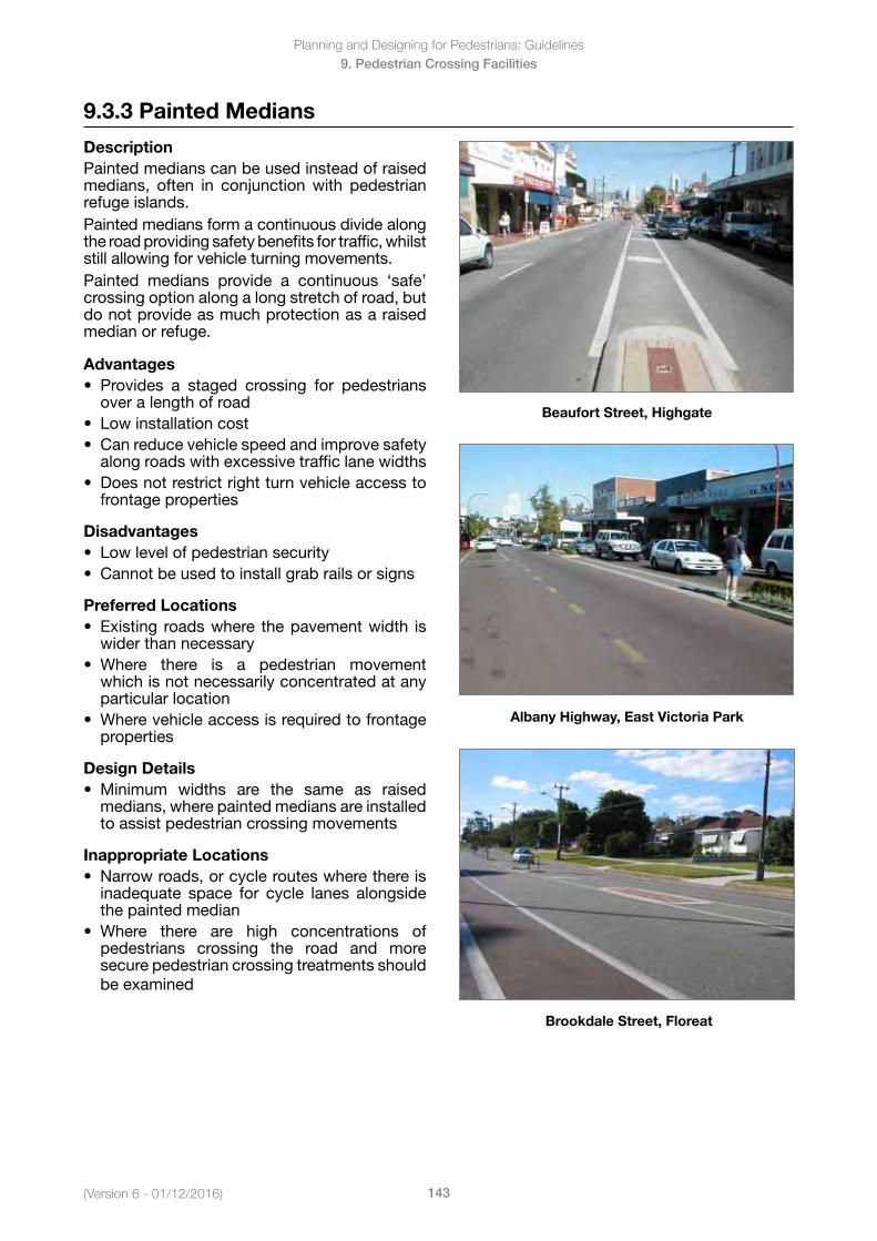
Planning and Designing for Pedestrians: Guidelines
143(Version 6 - 01/12/2016)
9. Pedestrian Crossing Facilities
9.3.3 Painted Medians
DescriptionPainted medians can be used instead of raised medians, often in conjunction with pedestrian refuge islands. Painted medians form a continuous divide along the road providing safety benefits for traffic, whilst still allowing for vehicle turning movements.Painted medians provide a continuous ‘safe’ crossing option along a long stretch of road, but do not provide as much protection as a raised median or refuge.
Advantages• Provides a staged crossing for pedestrians
over a length of road• Lowinstallationcost• Canreducevehiclespeedandimprovesafety
along roads with excessive traffic lane widths• Doesnotrestrictrightturnvehicleaccessto
frontage properties
Disadvantages• Lowlevelofpedestriansecurity• Cannotbeusedtoinstallgrabrailsorsigns
Preferred Locations• Existing roadswhere thepavementwidth is
wider than necessary• Where there is a pedestrian movement
which is not necessarily concentrated at any particular location
• Wherevehicleaccessisrequiredtofrontageproperties
Design Details• Minimum widths are the same as raised
medians, where painted medians are installed to assist pedestrian crossing movements
Inappropriate Locations• Narrowroads,orcyclerouteswherethereis
inadequate space for cycle lanes alongside the painted median
• Where there are high concentrations ofpedestrians crossing the road and more secure pedestrian crossing treatments should be examined
Beaufort Street, Highgate
Albany Highway, East Victoria Park
Brookdale Street, Floreat
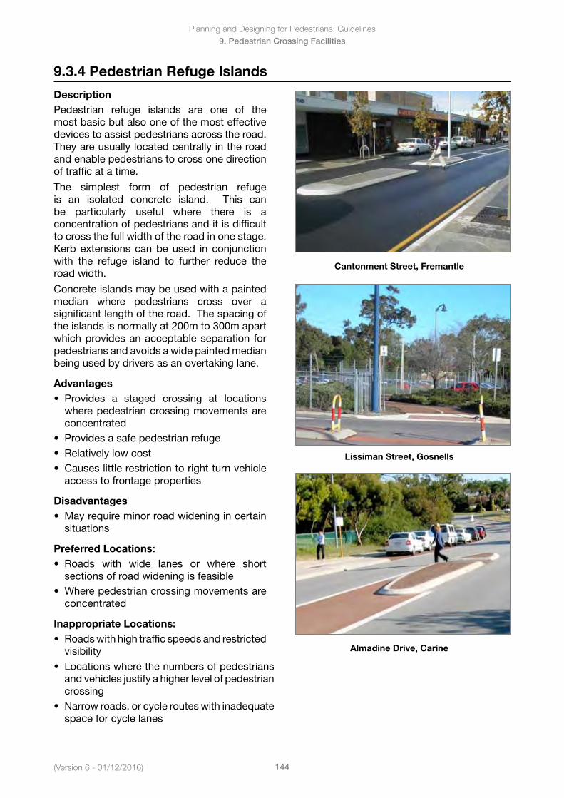
(Version 6 - 01/12/2016)
Planning and Designing for Pedestrians: Guidelines
144
9. Pedestrian Crossing Facilities
9.3.4 Pedestrian Refuge Islands
DescriptionPedestrian refuge islands are one of the most basic but also one of the most effective devices to assist pedestrians across the road. They are usually located centrally in the road and enable pedestrians to cross one direction of traffic at a time.
The simplest form of pedestrian refuge is an isolated concrete island. This can be particularly useful where there is a concentration of pedestrians and it is difficult to cross the full width of the road in one stage. Kerb extensions can be used in conjunction with the refuge island to further reduce the road width.
Concrete islands may be used with a painted median where pedestrians cross over a significant length of the road. The spacing of the islands is normally at 200m to 300m apart which provides an acceptable separation for pedestrians and avoids a wide painted median being used by drivers as an overtaking lane.
Advantages• Provides a staged crossing at locations
where pedestrian crossing movements areconcentrated
• Providesasafepedestrianrefuge• Relativelylowcost• Causeslittlerestrictiontorightturnvehicle
access to frontage properties
Disadvantages• Mayrequireminorroadwideningincertain
situations
Preferred Locations:• Roads with wide lanes or where short
sections of road widening is feasible• Wherepedestriancrossingmovementsare
concentrated
Inappropriate Locations:• Roadswithhightrafficspeedsandrestricted
visibility
Cantonment Street, Fremantle
Lissiman Street, Gosnells
Almadine Drive, Carine
• Locationswherethenumbersofpedestriansand vehicles justify a higher level of pedestrian crossing
• Narrowroads,orcyclerouteswithinadequatespace for cycle lanes
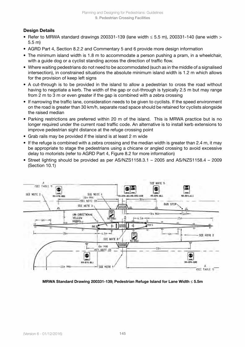
Planning and Designing for Pedestrians: Guidelines
145(Version 6 - 01/12/2016)
9. Pedestrian Crossing Facilities
Design Details• RefertoMRWAstandarddrawings200331-139(lanewidth≤5.5m),200331-140(lanewidth>
5.5 m)• AGRDPart4,Section8.2.2andCommentary5and6providemoredesigninformation• Theminimumislandwidthis1.8mtoaccommodateapersonpushingapram,inawheelchair,
with a guide dog or a cyclist standing across the direction of traffic flow.• Wherewaitingpedestriansdonotneedtobeaccommodated(suchasinthemiddleofasignalised
intersection), in constrained situations the absolute minimum island width is 1.2 m which allowsfor the provision of keep left signs
• Acut-through is tobeprovided in the island toallowapedestrian tocross the roadwithouthaving to negotiate a kerb. The width of the gap or cut-through is typically 2.5 m but may rangefrom 2 m to 3 m or even greater if the gap is combined with a zebra crossing
• Ifnarrowingthetrafficlane,considerationneedstobegiventocyclists.Ifthespeedenvironmenton the road is greater than 30 km/h, separate road space should be retained for cyclists alongsidethe raised median
• Parking restrictionsarepreferredwithin20mof the island. This isMRWApracticebut isnolonger required under the current road traffic code. An alternative is to install kerb extensions toimprove pedestrian sight distance at the refuge crossing point
• Grabrailsmaybeprovidediftheislandisatleast2mwide• Iftherefugeiscombinedwithazebracrossingandthemedianwidthisgreaterthan2.4m,itmay
be appropriate to stage the pedestrians using a chicane or angled crossing to avoid excessivedelay to motorists (refer to AGRD Part 4, Figure 8.2 for more information)
• Street lightingshouldbeprovidedasperAS/NZS1158.3.1–2005andAS/NZS1158.4–2009(Section 10.1)
MRWA Standard Drawing 200331-139; Pedestrian Refuge Island for Lane Width ≤ 5.5m
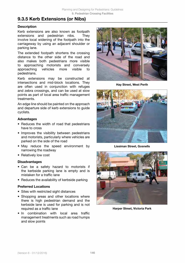
(Version 6 - 01/12/2016)
Planning and Designing for Pedestrians: Guidelines
146
9. Pedestrian Crossing Facilities
9.3.5 Kerb Extensions (or Nibs)
DescriptionKerb extensions are also known as footpath extensions and pedestrian nibs. They involve local widening of the footpath into the carriageway by using an adjacent shoulder or parking lane.
The extended footpath shortens the crossing distance to the other side of the road and also makes both pedestrians more visible to approaching motorists and conversely approaching vehicles more visible to pedestrians.
Kerb extensions may be constructed at intersections and mid-block locations. They are often used in conjunction with refuges and zebra crossings, and can be used at slow points as part of local area traffic management treatments.
An edge line should be painted on the approach and departure side of kerb extensions to guide cyclists.
Advantages• Reduces thewidthof road thatpedestrians
have to cross• Improves the visibility between pedestrians
and motorists, particularly where vehicles areparked on the side of the road
• May reduce the speed environment bynarrowing the roadway
• Relativelylowcost
Disadvantages• Can be a safety hazard to motorists if
the kerbside parking lane is empty and ismistaken for a traffic lane
• Reducestheavailabilityofkerbsideparking
Preferred Locations• Siteswithrestrictedsightdistances• Shopping areas and other locations where
there is high pedestrian demand and thekerbside lane is used for parking and is notrequired as a traffic lane
Hay Street, West Perth
Lissiman Street, Gosnells
Harper Street, Victoria Park
• In combination with local area trafficmanagement treatments such as road humpsand slow points
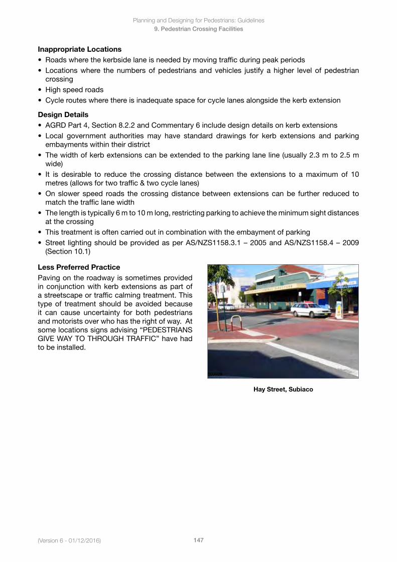
Planning and Designing for Pedestrians: Guidelines
147(Version 6 - 01/12/2016)
9. Pedestrian Crossing Facilities
Inappropriate Locations• Roadswherethekerbsidelaneisneededbymovingtrafficduringpeakperiods• Locationswhere thenumbersofpedestriansandvehicles justify ahigher level ofpedestrian
crossing• Highspeedroads• Cyclerouteswherethereisinadequatespaceforcyclelanesalongsidethekerbextension
Design Details• AGRDPart4,Section8.2.2andCommentary6includedesigndetailsonkerbextensions• Local government authorities may have standard drawings for kerb extensions and parking
embayments within their district• Thewidthofkerbextensionscanbeextendedtotheparkinglaneline(usually2.3mto2.5m
wide)• It is desirable to reduce the crossing distance between the extensions to amaximumof 10
metres (allows for two traffic & two cycle lanes)• Onslower speed roads thecrossingdistancebetweenextensionscanbe further reduced to
match the traffic lane width• Thelengthistypically6mto10mlong,restrictingparkingtoachievetheminimumsightdistances
at the crossing• Thistreatmentisoftencarriedoutincombinationwiththeembaymentofparking• Street lightingshouldbeprovidedasperAS/NZS1158.3.1–2005andAS/NZS1158.4–2009
(Section 10.1)
Less Preferred PracticePaving on the roadway is sometimes provided in conjunction with kerb extensions as part of a streetscape or traffic calming treatment. This type of treatment should be avoided because it can cause uncertainty for both pedestrians and motorists over who has the right of way. At some locations signs advising “PEDESTRIANS GIVEWAYTOTHROUGHTRAFFIC”havehadto be installed.
Hay Street, Subiaco
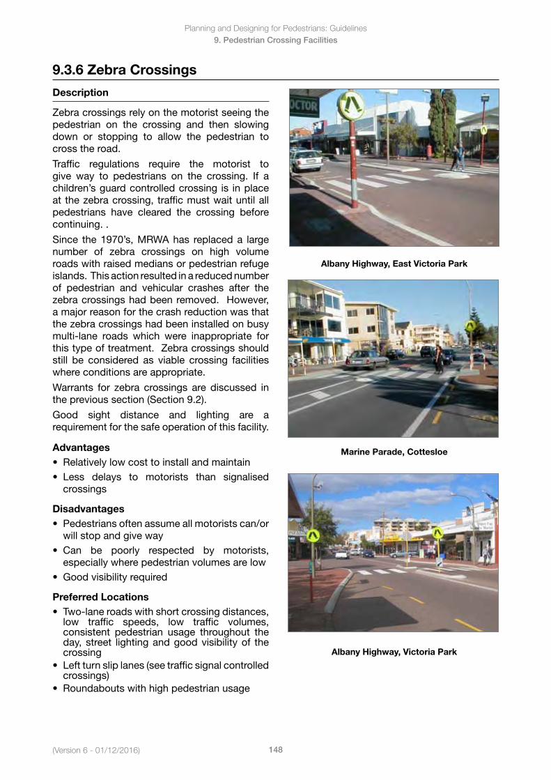
(Version 6 - 01/12/2016)
Planning and Designing for Pedestrians: Guidelines
148
9. Pedestrian Crossing Facilities
9.3.6 Zebra Crossings
Description
Zebra crossings rely on the motorist seeing the pedestrian on the crossing and then slowing down or stopping to allow the pedestrian to cross the road.
Traffic regulations require the motorist to give way to pedestrians on the crossing. If a children’s guard controlled crossing is in place at the zebra crossing, traffic must wait until all pedestrians have cleared the crossing before continuing. .
Since the 1970’s, MRWA has replaced a large number of zebra crossings on high volume roads with raised medians or pedestrian refuge islands. This action resulted in a reduced number of pedestrian and vehicular crashes after the zebracrossingshadbeenremoved.However,a major reason for the crash reduction was that the zebra crossings had been installed on busy multi-lane roads which were inappropriate for this type of treatment. Zebra crossings should still be considered as viable crossing facilities where conditions are appropriate.
Warrants for zebra crossings are discussed in the previous section (Section 9.2).
Good sight distance and lighting are a requirement for the safe operation of this facility.
Advantages• Relativelylowcosttoinstallandmaintain• Less delays to motorists than signalised
crossings
Disadvantages• Pedestriansoftenassumeallmotoristscan/or
will stop and give way• Can be poorly respected by motorists,
especially where pedestrian volumes are low• Goodvisibilityrequired
Preferred Locations• Two-lane roads with short crossing distances,
low traffic speeds, low traffic volumes, consistent pedestrian usage throughout the day, street lighting and good visibility of the crossing
• Leftturnsliplanes(seetrafficsignalcontrolledcrossings)
• Roundaboutswithhighpedestrianusage
Albany Highway, East Victoria Park
Marine Parade, Cottesloe
Albany Highway, Victoria Park
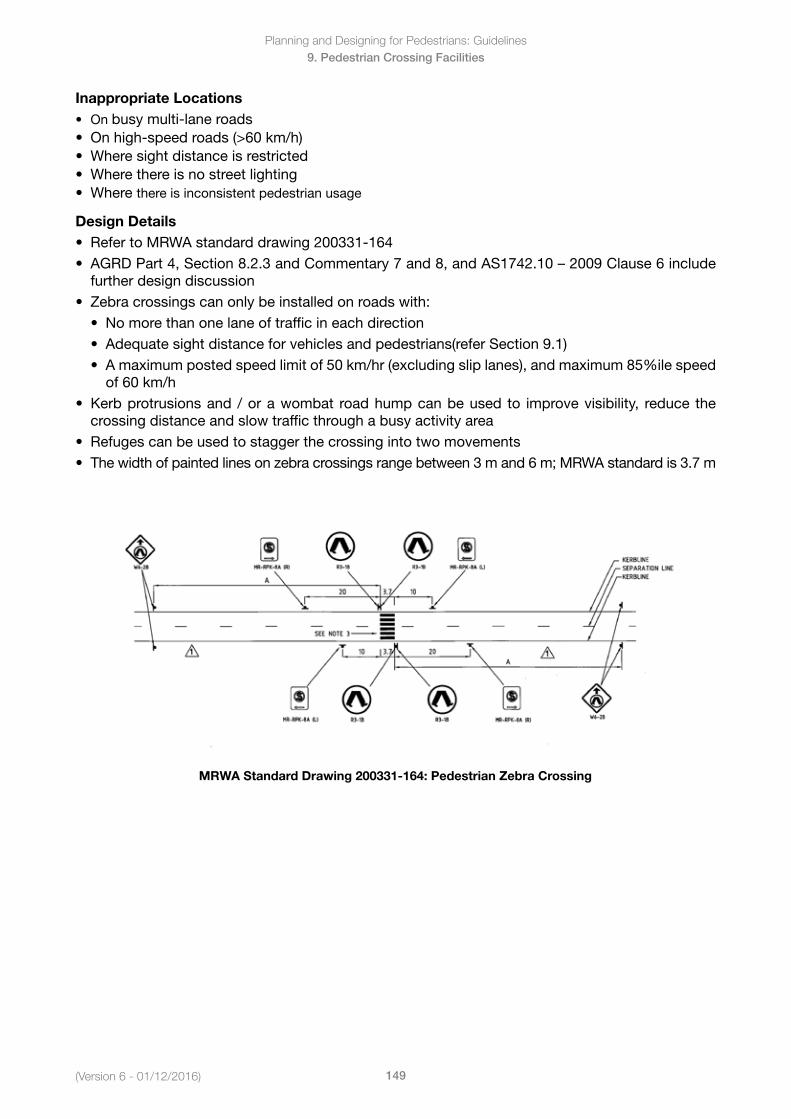
Planning and Designing for Pedestrians: Guidelines
149(Version 6 - 01/12/2016)
9. Pedestrian Crossing Facilities
Inappropriate Locations• On busy multi-lane roads• Onhigh-speedroads(>60km/h)• Wheresightdistanceisrestricted• Wherethereisnostreetlighting• Wherethere is inconsistent pedestrian usage
Design Details• RefertoMRWAstandarddrawing200331-164• AGRDPart4,Section8.2.3andCommentary7and8,andAS1742.10–2009Clause6include
further design discussion• Zebracrossingscanonlybeinstalledonroadswith:
• Nomorethanonelaneoftrafficineachdirection• Adequatesightdistanceforvehiclesandpedestrians(referSection9.1)• Amaximumpostedspeedlimitof50km/hr(excludingsliplanes),andmaximum85%ilespeed
of 60 km/h• Kerbprotrusionsand /orawombat roadhumpcanbeused to improvevisibility, reduce the
crossing distance and slow traffic through a busy activity area• Refugescanbeusedtostaggerthecrossingintotwomovements• Thewidthofpaintedlinesonzebracrossingsrangebetween3mand6m;MRWAstandardis3.7m
MRWA Standard Drawing 200331-164: Pedestrian Zebra Crossing
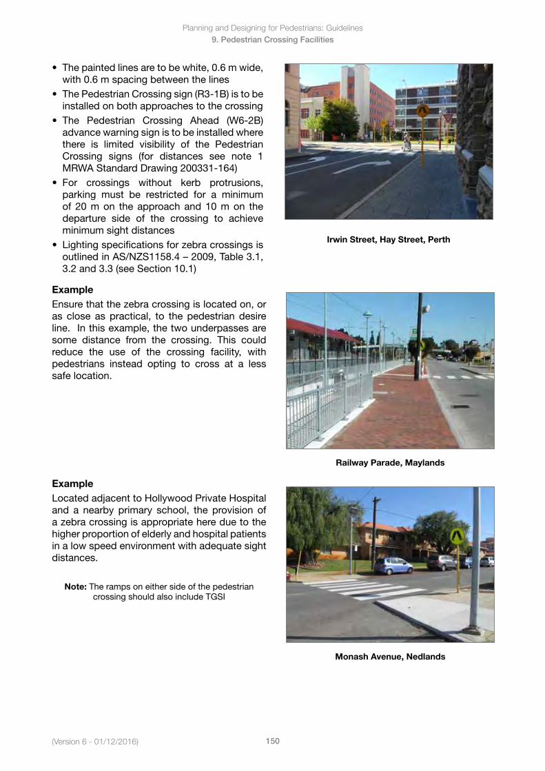
(Version 6 - 01/12/2016)
Planning and Designing for Pedestrians: Guidelines
150
9. Pedestrian Crossing Facilities
• Thepaintedlinesaretobewhite,0.6mwide,with 0.6 m spacing between the lines
• ThePedestrianCrossingsign(R3-1B)istobeinstalled on both approaches to the crossing
• The Pedestrian Crossing Ahead (W6-2B)advance warning sign is to be installed wherethere is limited visibility of the PedestrianCrossing signs (for distances see note 1MRWA Standard Drawing 200331-164)
• For crossings without kerb protrusions,parking must be restricted for a minimumof 20 m on the approach and 10 m on thedeparture side of the crossing to achieveminimum sight distances
• LightingspecificationsforzebracrossingsisoutlinedinAS/NZS1158.4–2009,Table3.1,3.2 and 3.3 (see Section 10.1)
Irwin Street, Hay Street, Perth
ExampleEnsure that the zebra crossing is located on, or as close as practical, to the pedestrian desire line. In this example, the two underpasses are some distance from the crossing. This could reduce the use of the crossing facility, with pedestrians instead opting to cross at a less safe location.
Railway Parade, Maylands
Example LocatedadjacenttoHollywoodPrivateHospitaland a nearby primary school, the provision of a zebra crossing is appropriate here due to the higher proportion of elderly and hospital patients in a low speed environment with adequate sight distances.
Note: The ramps on either side of the pedestrian crossing should also include TGSI
Monash Avenue, Nedlands
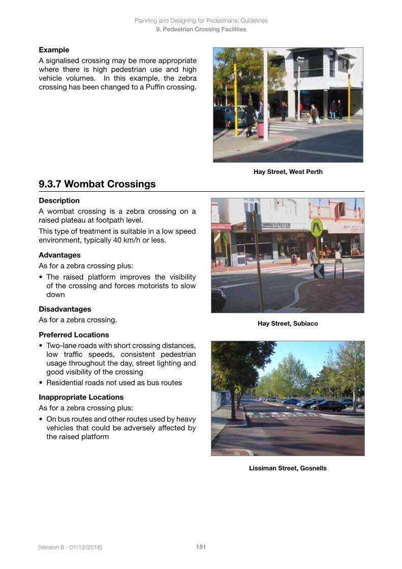
Planning and Designing for Pedestrians: Guidelines
151(Version 6 - 01/12/2016)
9. Pedestrian Crossing Facilities
ExampleA signalised crossing may be more appropriate where there is high pedestrian use and high vehicle volumes. In this example, the zebra crossing has been changed to a Puffin crossing.
Hay Street, West Perth
9.3.7 Wombat Crossings
DescriptionA wombat crossing is a zebra crossing on a raised plateau at footpath level.
This type of treatment is suitable in a low speed environment, typically 40 km/h or less.
AdvantagesAs for a zebra crossing plus:
• The raised platform improves the visibilityof the crossing and forces motorists to slowdown
DisadvantagesAs for a zebra crossing.
Preferred Locations• Two-laneroadswithshortcrossingdistances,
low traffic speeds, consistent pedestrianusage throughout the day, street lighting andgood visibility of the crossing
• Residentialroadsnotusedasbusroutes
Inappropriate LocationsAs for a zebra crossing plus:
• Onbusroutesandotherroutesusedbyheavyvehicles that could be adversely affected bythe raised platform
Hay Street, Subiaco
Lissiman Street, Gosnells
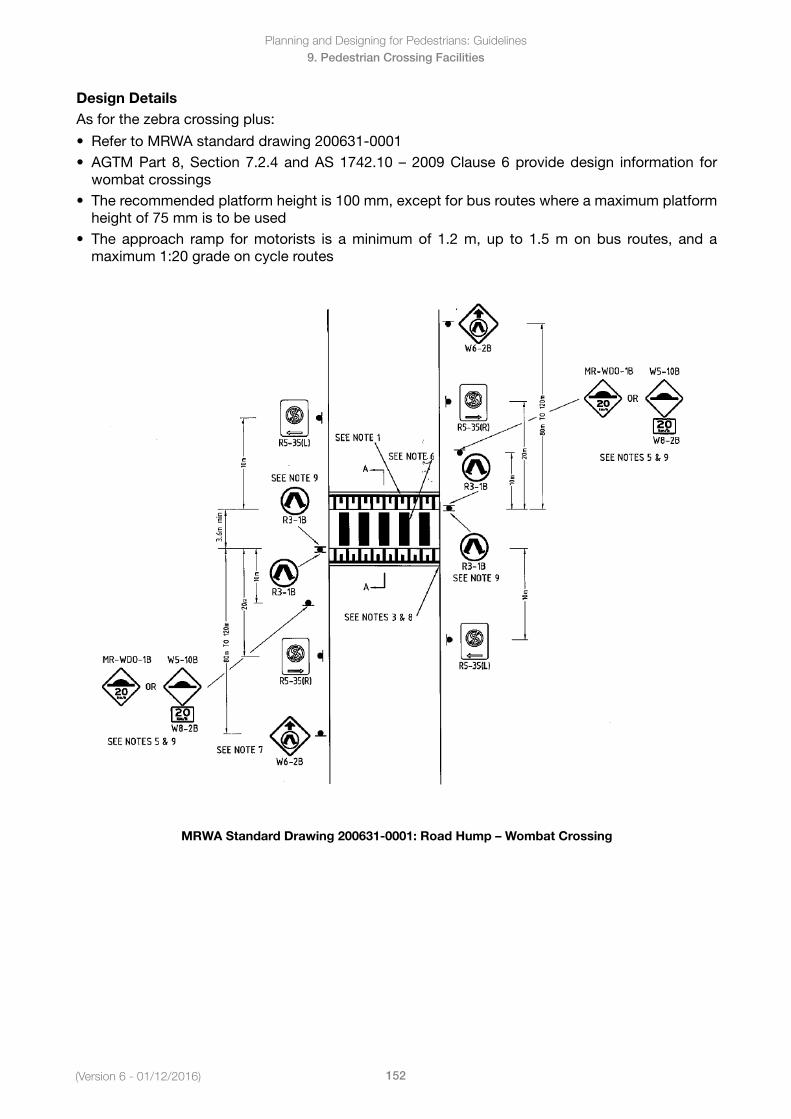
(Version 6 - 01/12/2016)
Planning and Designing for Pedestrians: Guidelines
152
9. Pedestrian Crossing Facilities
Design DetailsAs for the zebra crossing plus:
• RefertoMRWAstandarddrawing200631-0001• AGTMPart8,Section7.2.4andAS1742.10–2009Clause6providedesign information for
wombat crossings• Therecommendedplatformheightis100mm,exceptforbusrouteswhereamaximumplatform
height of 75 mm is to be used• The approach ramp formotorists is aminimumof 1.2m, up to 1.5monbus routes, and a
maximum 1:20 grade on cycle routes
MRWA Standard Drawing 200631-0001: Road Hump – Wombat Crossing
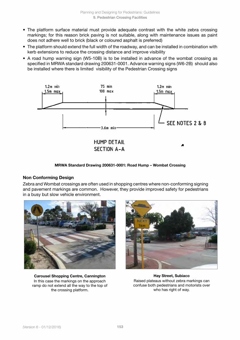
Planning and Designing for Pedestrians: Guidelines
153(Version 6 - 01/12/2016)
9. Pedestrian Crossing Facilities
• The platform surfacematerialmust provide adequate contrastwith thewhite zebra crossingmarkings; for this reason brick paving is not suitable, along with maintenance issues as paintdoes not adhere well to brick (black or coloured asphalt is preferred)
• Theplatformshouldextendthefullwidthoftheroadway,andcanbeinstalledincombinationwithkerb extensions to reduce the crossing distance and improve visibility
• Aroadhumpwarningsign (W5-10B) is tobe installed inadvanceof thewombatcrossingasspecified in MRWA standard drawing 200631-0001. Advance warning signs (W6-2B) should alsobe installed where there is limited visibility of the Pedestrian Crossing signs
MRWA Standard Drawing 200631-0001: Road Hump – Wombat Crossing
Non Conforming DesignZebra and Wombat crossings are often used in shopping centres where non-conforming signing andpavementmarkingsarecommon.However,theyprovideimprovedsafetyforpedestriansin a busy but slow vehicle environment.
Carousel Shopping Centre, CanningtonIn this case the markings on the approach
ramp do not extend all the way to the top of the crossing platform.
Hay Street, SubiacoRaised plateaus without zebra markings can confuse both pedestrians and motorists over
who has right of way.
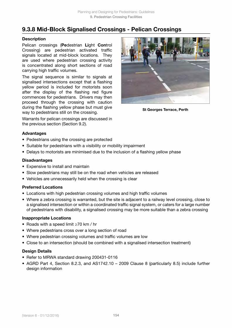
(Version 6 - 01/12/2016)
Planning and Designing for Pedestrians: Guidelines
154
9. Pedestrian Crossing Facilities
9.3.8 Mid-Block Signalised Crossings - Pelican Crossings
DescriptionPelican crossings (Pedestrian Light Control Crossing) are pedestrian activated traffic signals located at mid-block locations. They are used where pedestrian crossing activity is concentrated along short sections of road carrying high traffic volumes.
The signal sequence is similar to signals at signalised intersections except that a flashing yellow period is included for motorists soon after the display of the flashing red figure commences for pedestrians. Drivers may then proceed through the crossing with caution during the flashing yellow phase but must give way to pedestrians still on the crossing.
Warrants for pelican crossings are discussed in the previous section (Section 9.2).
St Georges Terrace, Perth
Advantages• Pedestriansusingthecrossingareprotected• Suitableforpedestrianswithavisibilityormobilityimpairment• Delaystomotoristsareminimisedduetotheinclusionofaflashingyellowphase
Disadvantages • Expensivetoinstallandmaintain• Slowpedestriansmaystillbeontheroadwhenvehiclesarereleased• Vehiclesareunnecessarilyheldwhenthecrossingisclear
Preferred Locations• Locationswithhighpedestriancrossingvolumesandhightrafficvolumes• Whereazebracrossingiswarranted,butthesiteisadjacenttoarailwaylevelcrossing,closeto
a signalised intersection or within a coordinated traffic signal system, or caters for a large numberof pedestrians with disability, a signalised crossing may be more suitable than a zebra crossing
Inappropriate Locations• Roadswithaspeedlimit≥70km/hr• Wherepedestrianscrossoveralongsectionofroad• Wherepedestriancrossingvolumesandtrafficvolumesarelow• Closetoanintersection(shouldbecombinedwithasignalisedintersectiontreatment)
Design Details• RefertoMRWAstandarddrawing200431-0116• AGRDPart4,Section8.2.3,andAS1742.10–2009Clause8 (particularly8.5) include further
design information
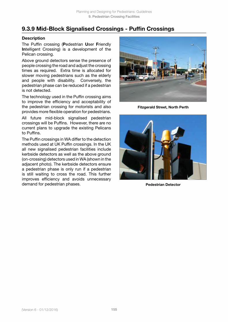
Planning and Designing for Pedestrians: Guidelines
155(Version 6 - 01/12/2016)
9. Pedestrian Crossing Facilities
9.3.9 Mid-Block Signalised Crossings - Puffin Crossings
DescriptionThe Puffin crossing (Pedestrian User Friendly Intelligent Crossing) is a development of the Pelican crossing.
Above ground detectors sense the presence of people crossing the road and adjust the crossing times as required. Extra time is allocated for slower moving pedestrians such as the elderly and people with disability. Conversely, the pedestrian phase can be reduced if a pedestrian is not detected.
The technology used in the Puffin crossing aims to improve the efficiency and acceptability of the pedestrian crossing for motorists and also provides more flexible operation for pedestrians.
All future mid-block signalised pedestrian crossingswillbePuffins.However,therearenocurrent plans to upgrade the existing Pelicans to Puffins.
The Puffin crossings in WA differ to the detection methods used at UK Puffin crossings. In the UK all new signalised pedestrian facilities include kerbside detectors as well as the above ground (on-crossing) detectors used in WA (shown in the adjacent photo). The kerbside detectors ensure a pedestrian phase is only run if a pedestrian is still waiting to cross the road. This further improves efficiency and avoids unnecessary demand for pedestrian phases.
Fitzgerald Street, North Perth
Pedestrian Detector
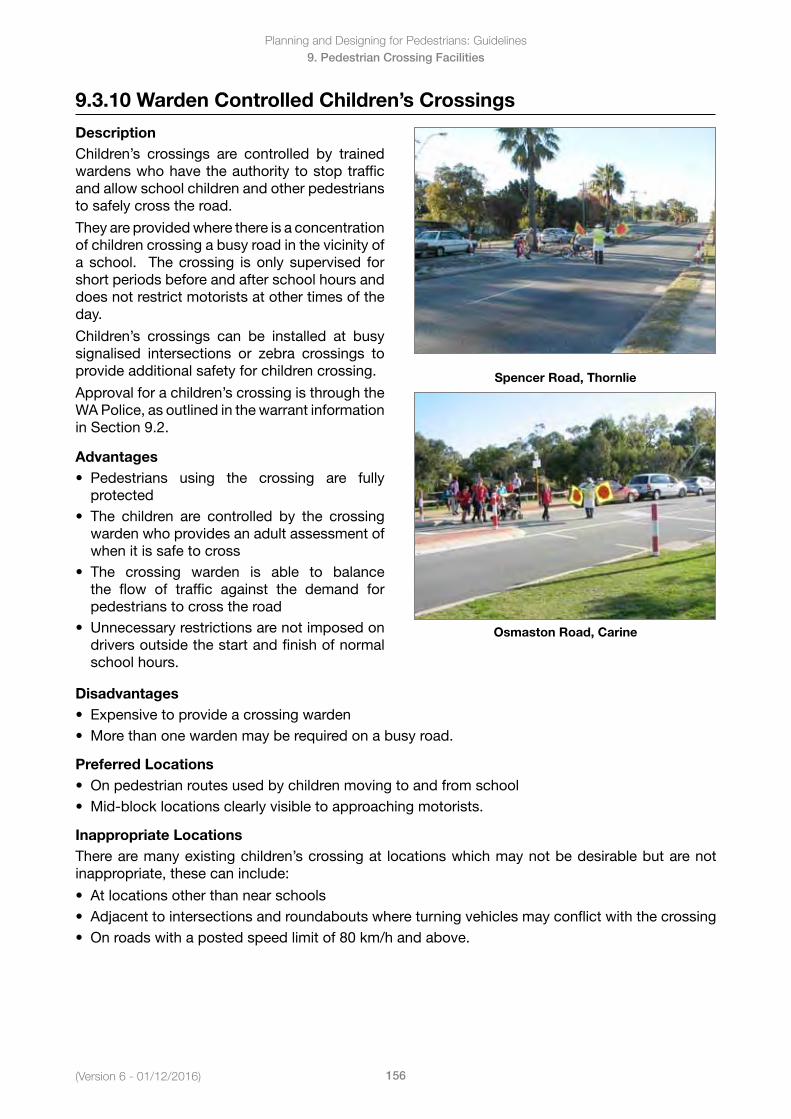
(Version 6 - 01/12/2016)
Planning and Designing for Pedestrians: Guidelines
156
9. Pedestrian Crossing Facilities
9.3.10 Warden Controlled Children’s Crossings
DescriptionChildren’s crossings are controlled by trained wardens who have the authority to stop traffic and allow school children and other pedestrians to safely cross the road.
They are provided where there is a concentration of children crossing a busy road in the vicinity of a school. The crossing is only supervised for short periods before and after school hours and does not restrict motorists at other times of the day.
Children’s crossings can be installed at busy signalised intersections or zebra crossings to provide additional safety for children crossing.
Approval for a children’s crossing is through the WA Police, as outlined in the warrant information in Section 9.2.
Advantages• Pedestrians using the crossing are fully
protected• The children are controlled by the crossing
warden who provides an adult assessment ofwhen it is safe to cross
• The crossing warden is able to balancethe flow of traffic against the demand forpedestrians to cross the road
• Unnecessaryrestrictionsarenotimposedondrivers outside the start and finish of normalschool hours.
Spencer Road, Thornlie
Osmaston Road, Carine
Disadvantages• Expensivetoprovideacrossingwarden• Morethanonewardenmayberequiredonabusyroad.
Preferred Locations• Onpedestrianroutesusedbychildrenmovingtoandfromschool• Mid-blocklocationsclearlyvisibletoapproachingmotorists.
Inappropriate LocationsThere are many existing children’s crossing at locations which may not be desirable but are not inappropriate, these can include:
• Atlocationsotherthannearschools• Adjacenttointersectionsandroundaboutswhereturningvehiclesmayconflictwiththecrossing• Onroadswithapostedspeedlimitof80km/handabove.
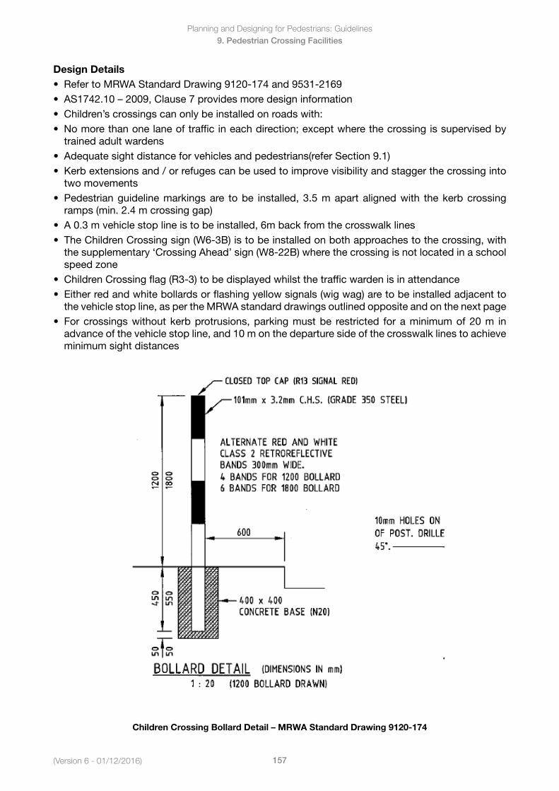
Planning and Designing for Pedestrians: Guidelines
157(Version 6 - 01/12/2016)
9. Pedestrian Crossing Facilities
Design Details• RefertoMRWAStandardDrawing9120-174and9531-2169• AS1742.10–2009,Clause7providesmoredesigninformation• Children’scrossingscanonlybeinstalledonroadswith:• Nomorethanonelaneoftrafficineachdirection;exceptwherethecrossingissupervisedby
trained adult wardens• Adequatesightdistanceforvehiclesandpedestrians(referSection9.1)• Kerbextensionsand/orrefugescanbeusedtoimprovevisibilityandstaggerthecrossinginto
two movements• Pedestrianguidelinemarkingsare tobe installed,3.5mapartalignedwith thekerbcrossing
ramps (min. 2.4 m crossing gap)• A0.3mvehiclestoplineistobeinstalled,6mbackfromthecrosswalklines• TheChildrenCrossingsign(W6-3B)istobeinstalledonbothapproachestothecrossing,with
the supplementary ‘Crossing Ahead’ sign (W8-22B) where the crossing is not located in a schoolspeed zone
• ChildrenCrossingflag(R3-3)tobedisplayedwhilstthetrafficwardenisinattendance• Eitherredandwhitebollardsorflashingyellowsignals(wigwag)aretobeinstalledadjacentto
the vehicle stop line, as per the MRWA standard drawings outlined opposite and on the next page• Forcrossingswithoutkerbprotrusions,parkingmustbe restricted foraminimumof20m in
advance of the vehicle stop line, and 10 m on the departure side of the crosswalk lines to achieveminimum sight distances
Children Crossing Bollard Detail – MRWA Standard Drawing 9120-174
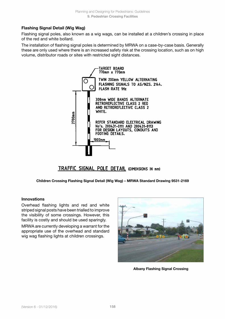
(Version 6 - 01/12/2016)
Planning and Designing for Pedestrians: Guidelines
158
9. Pedestrian Crossing Facilities
Flashing Signal Detail (Wig Wag)Flashing signal poles, also known as a wig wags, can be installed at a children’s crossing in place of the red and white bollard.
The installation of flashing signal poles is determined by MRWA on a case-by-case basis. Generally these are only used where there is an increased safety risk at the crossing location, such as on high volume, distributor roads or sites with restricted sight distances.
Children Crossing Flashing Signal Detail (Wig Wag) – MRWA Standard Drawing 9531-2169
InnovationsOverhead flashing lights and red and white striped signal posts have been trialled to improve the visibility of some crossings.However, thisfacility is costly and should be used sparingly.
MRWA are currently developing a warrant for the appropriate use of the overhead and standard wig wag flashing lights at children crossings.
Albany Flashing Signal Crossing
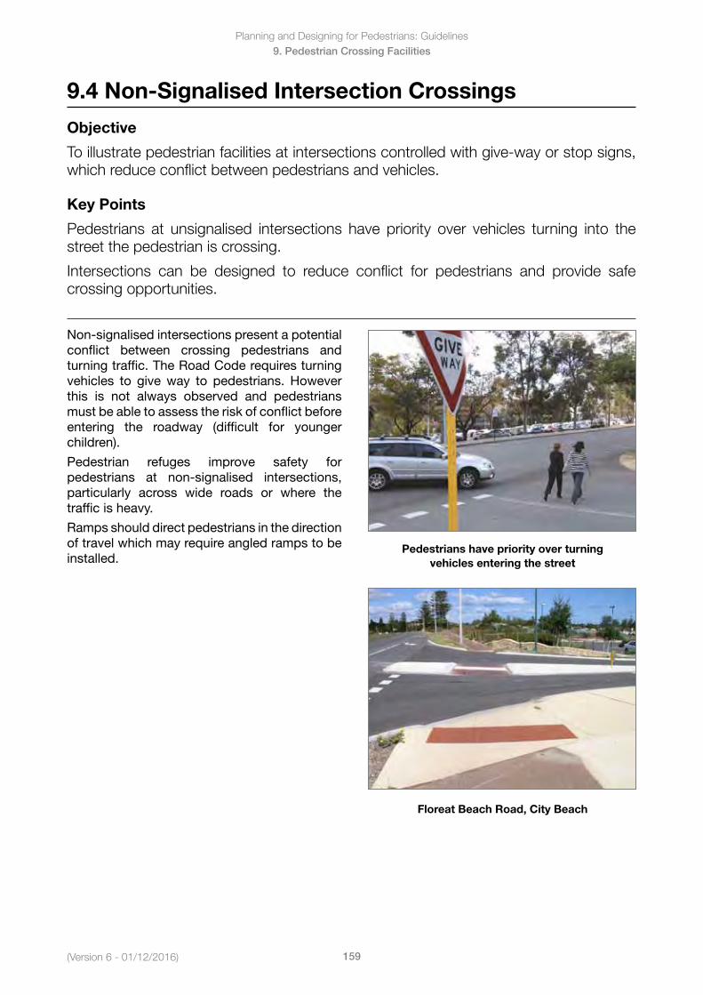
Planning and Designing for Pedestrians: Guidelines
159(Version 6 - 01/12/2016)
9. Pedestrian Crossing Facilities
9.4 Non-Signalised Intersection Crossings
Objective
To illustrate pedestrian facilities at intersections controlled with give-way or stop signs, which reduce conflict between pedestrians and vehicles.
Key Points
Pedestrians at unsignalised intersections have priority over vehicles turning into the street the pedestrian is crossing.
Intersections can be designed to reduce conflict for pedestrians and provide safe crossing opportunities.
Non-signalised intersections present a potential conflict between crossing pedestrians and turning traffic. The Road Code requires turning vehicles to giveway to pedestrians. Howeverthis is not always observed and pedestrians must be able to assess the risk of conflict before entering the roadway (difficult for younger children).
Pedestrian refuges improve safety for pedestrians at non-signalised intersections, particularly across wide roads or where the traffic is heavy.
Ramps should direct pedestrians in the direction of travel which may require angled ramps to be installed.
Pedestrians have priority over turning vehicles entering the street
Floreat Beach Road, City Beach
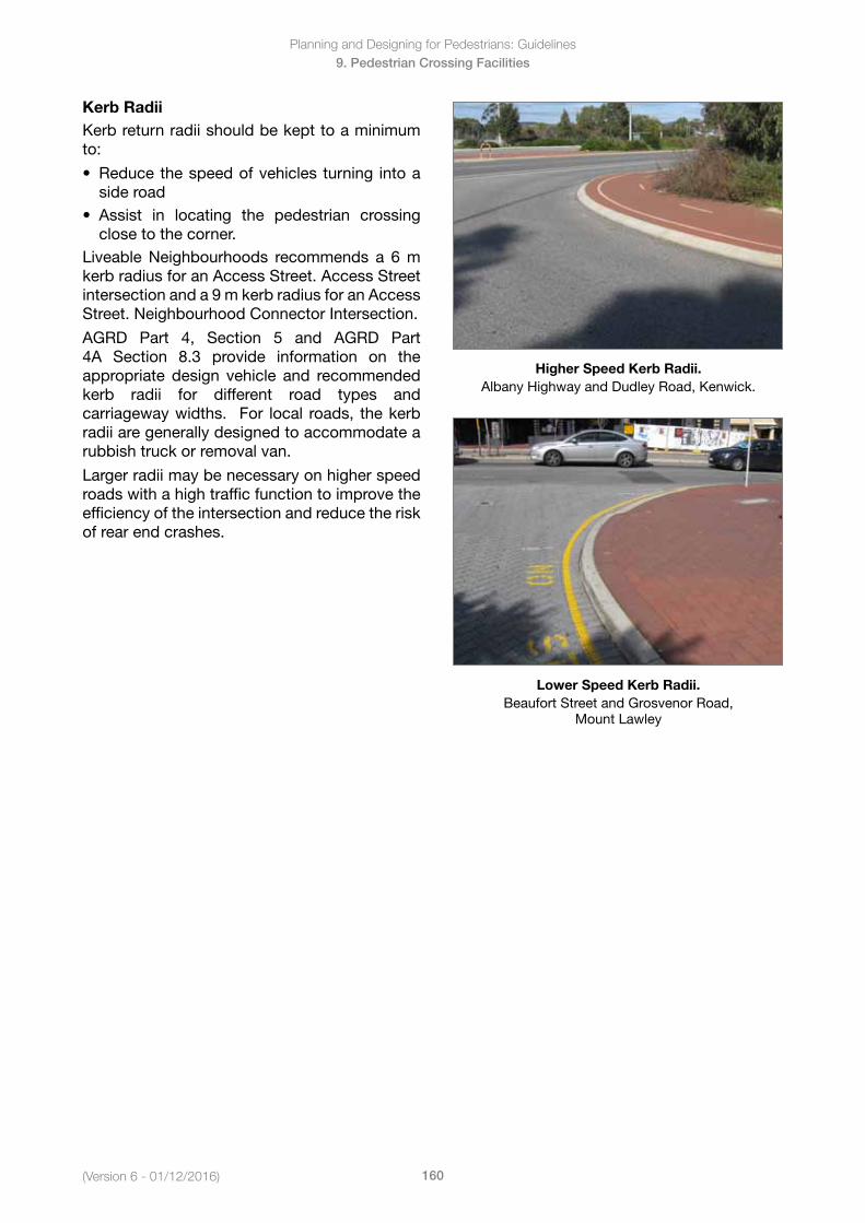
(Version 6 - 01/12/2016)
Planning and Designing for Pedestrians: Guidelines
160
9. Pedestrian Crossing Facilities
Kerb RadiiKerb return radii should be kept to a minimum to:
• Reducethespeedofvehicles turning intoaside road
• Assist in locating the pedestrian crossingclose to the corner.
Liveable Neighbourhoods recommends a 6 m kerb radius for an Access Street. Access Street intersection and a 9 m kerb radius for an Access Street. Neighbourhood Connector Intersection.
AGRD Part 4, Section 5 and AGRD Part 4A Section 8.3 provide information on the appropriate design vehicle and recommended kerb radii for different road types and carriageway widths. For local roads, the kerb radii are generally designed to accommodate a rubbish truck or removal van.
Larger radii may be necessary on higher speed roads with a high traffic function to improve the efficiency of the intersection and reduce the risk of rear end crashes.
Higher Speed Kerb Radii.AlbanyHighwayandDudleyRoad,Kenwick.
Lower Speed Kerb Radii.Beaufort Street and Grosvenor Road,
Mount Lawley
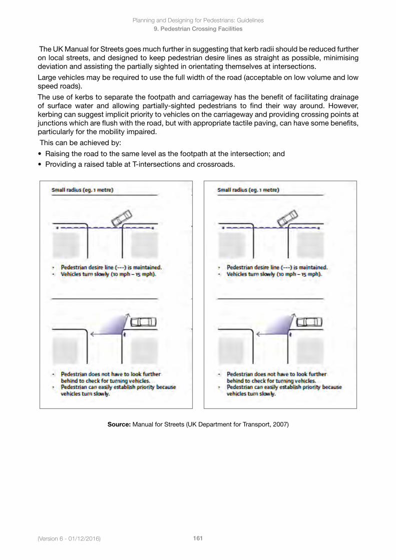
Planning and Designing for Pedestrians: Guidelines
161(Version 6 - 01/12/2016)
9. Pedestrian Crossing Facilities
The UK Manual for Streets goes much further in suggesting that kerb radii should be reduced further on local streets, and designed to keep pedestrian desire lines as straight as possible, minimising deviation and assisting the partially sighted in orientating themselves at intersections.
Large vehicles may be required to use the full width of the road (acceptable on low volume and low speed roads).
The use of kerbs to separate the footpath and carriageway has the benefit of facilitating drainage of surface water and allowing partially-sighted pedestrians to find their way around. However,kerbing can suggest implicit priority to vehicles on the carriageway and providing crossing points at junctions which are flush with the road, but with appropriate tactile paving, can have some benefits, particularly for the mobility impaired.
This can be achieved by:
• Raisingtheroadtothesamelevelasthefootpathattheintersection;and• ProvidingaraisedtableatT-intersectionsandcrossroads.
Source: Manual for Streets (UK Department for Transport, 2007)
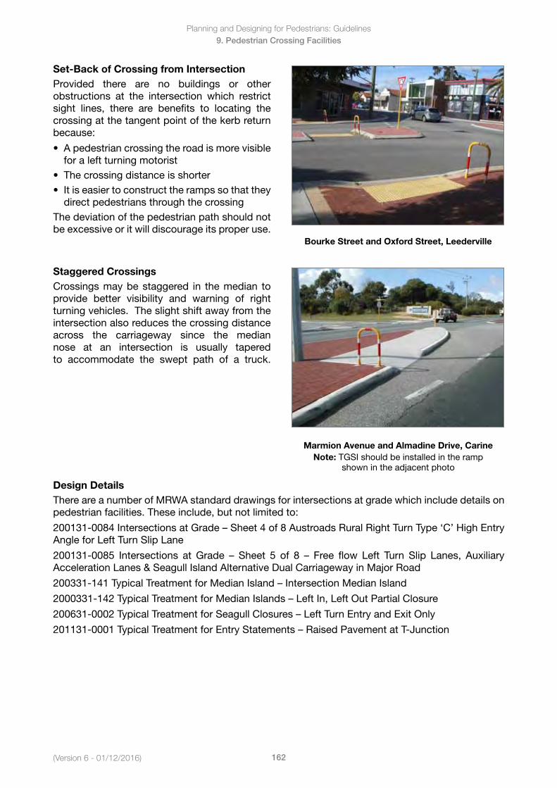
(Version 6 - 01/12/2016)
Planning and Designing for Pedestrians: Guidelines
162
9. Pedestrian Crossing Facilities
Set-Back of Crossing from IntersectionProvided there are no buildings or other obstructions at the intersection which restrict sight lines, there are benefits to locating the crossing at the tangent point of the kerb return because:
• Apedestriancrossingtheroadismorevisiblefor a left turning motorist
• Thecrossingdistanceisshorter• Itiseasiertoconstructtherampssothatthey
direct pedestrians through the crossingThe deviation of the pedestrian path should not be excessive or it will discourage its proper use.
Bourke Street and Oxford Street, Leederville
Staggered CrossingsCrossings may be staggered in the median to provide better visibility and warning of right turning vehicles. The slight shift away from the intersection also reduces the crossing distance across the carriageway since the median nose at an intersection is usually tapered to accommodate the swept path of a truck.
Marmion Avenue and Almadine Drive, CarineNote: TGSI should be installed in the ramp
shown in the adjacent photo
Design DetailsThere are a number of MRWA standard drawings for intersections at grade which include details on pedestrian facilities. These include, but not limited to:
200131-0084IntersectionsatGrade–Sheet4of8AustroadsRuralRightTurnType‘C’HighEntryAngle for Left Turn Slip Lane
200131-0085 Intersections atGrade – Sheet 5 of 8 – Free flow Left Turn Slip Lanes, AuxiliaryAcceleration Lanes & Seagull Island Alternative Dual Carriageway in Major Road
200331-141TypicalTreatmentforMedianIsland–IntersectionMedianIsland
2000331-142TypicalTreatmentforMedianIslands–LeftIn,LeftOutPartialClosure
200631-0002TypicalTreatmentforSeagullClosures–LeftTurnEntryandExitOnly
201131-0001TypicalTreatmentforEntryStatements–RaisedPavementatT-Junction
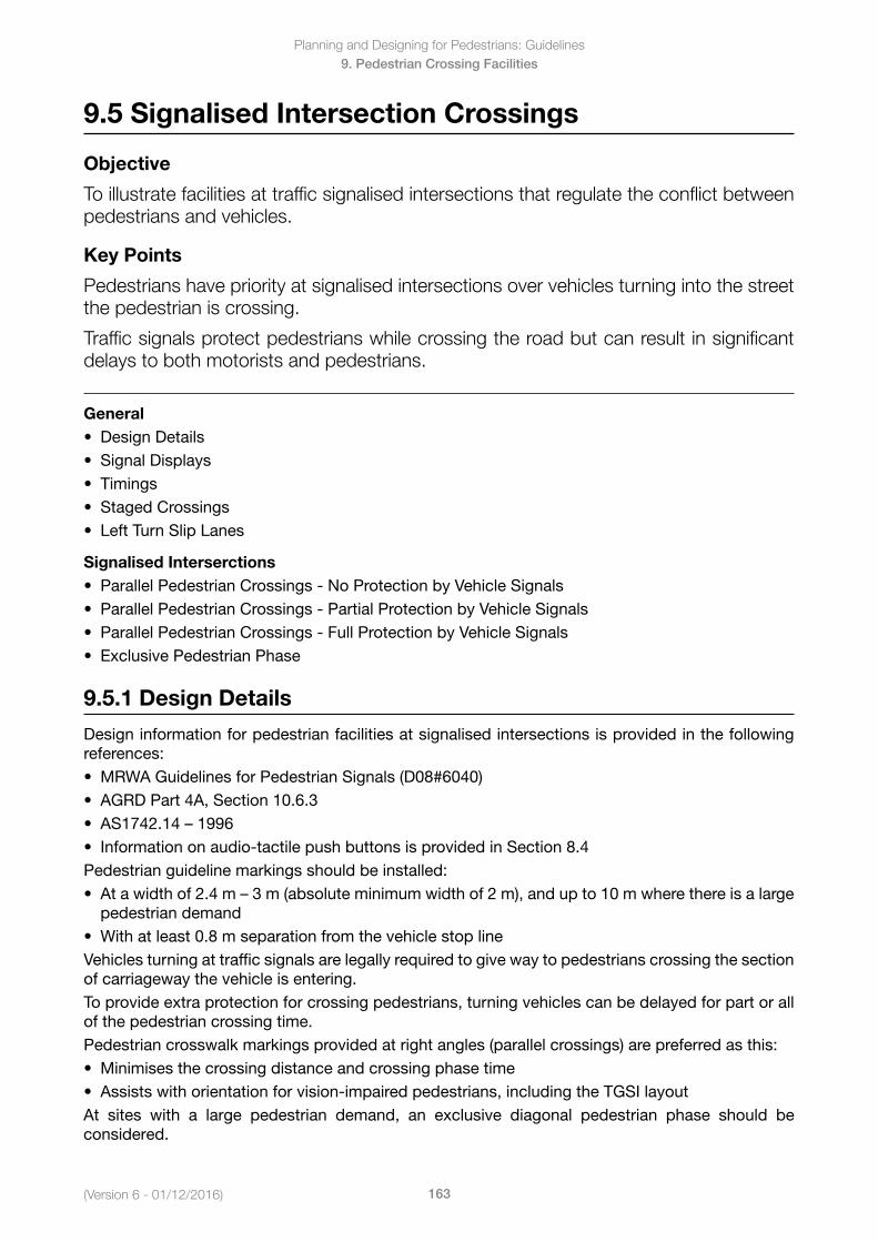
Planning and Designing for Pedestrians: Guidelines
163(Version 6 - 01/12/2016)
9. Pedestrian Crossing Facilities
9.5 Signalised Intersection Crossings
Objective
To illustrate facilities at traffic signalised intersections that regulate the conflict between pedestrians and vehicles.
Key Points
Pedestrians have priority at signalised intersections over vehicles turning into the street the pedestrian is crossing.
Traffic signals protect pedestrians while crossing the road but can result in significant delays to both motorists and pedestrians.
General• DesignDetails• SignalDisplays• Timings• StagedCrossings• LeftTurnSlipLanes
Signalised Interserctions• ParallelPedestrianCrossings-NoProtectionbyVehicleSignals• ParallelPedestrianCrossings-PartialProtectionbyVehicleSignals• ParallelPedestrianCrossings-FullProtectionbyVehicleSignals• ExclusivePedestrianPhase
9.5.1 Design Details
Design information for pedestrian facilities at signalised intersections is provided in the following references:• MRWAGuidelinesforPedestrianSignals(D08#6040)• AGRDPart4A,Section10.6.3• AS1742.14–1996• Informationonaudio-tactilepushbuttonsisprovidedinSection8.4Pedestrian guideline markings should be installed:• Atawidthof2.4m–3m(absoluteminimumwidthof2m),andupto10mwherethereisalarge
pedestrian demand• Withatleast0.8mseparationfromthevehiclestoplineVehicles turning at traffic signals are legally required to give way to pedestrians crossing the section of carriageway the vehicle is entering.To provide extra protection for crossing pedestrians, turning vehicles can be delayed for part or all of the pedestrian crossing time. Pedestrian crosswalk markings provided at right angles (parallel crossings) are preferred as this:• Minimisesthecrossingdistanceandcrossingphasetime• Assistswithorientationforvision-impairedpedestrians,includingtheTGSIlayoutAt sites with a large pedestrian demand, an exclusive diagonal pedestrian phase should be considered.
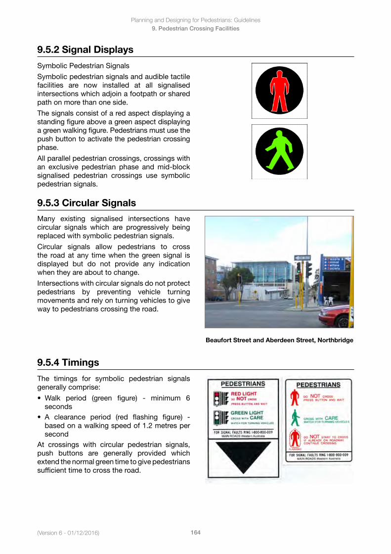
(Version 6 - 01/12/2016)
Planning and Designing for Pedestrians: Guidelines
164
9. Pedestrian Crossing Facilities
9.5.2 Signal Displays
Symbolic Pedestrian Signals
Symbolic pedestrian signals and audible tactile facilities are now installed at all signalised intersections which adjoin a footpath or shared path on more than one side.
The signals consist of a red aspect displaying a standing figure above a green aspect displaying a green walking figure. Pedestrians must use the push button to activate the pedestrian crossing phase.
All parallel pedestrian crossings, crossings with an exclusive pedestrian phase and mid-block signalised pedestrian crossings use symbolic pedestrian signals.
9.5.3 Circular Signals
Many existing signalised intersections have circular signals which are progressively being replaced with symbolic pedestrian signals.
Circular signals allow pedestrians to cross the road at any time when the green signal is displayed but do not provide any indication when they are about to change.
Intersections with circular signals do not protect pedestrians by preventing vehicle turning movements and rely on turning vehicles to give way to pedestrians crossing the road.
Beaufort Street and Aberdeen Street, Northbridge
9.5.4 Timings
The timings for symbolic pedestrian signals generally comprise:
• Walk period (green figure) - minimum 6seconds
• A clearance period (red flashing figure) -based on a walking speed of 1.2 metres persecond
At crossings with circular pedestrian signals, push buttons are generally provided which extend the normal green time to give pedestrians sufficient time to cross the road.
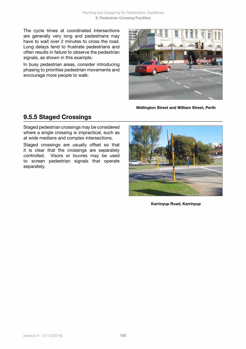
Planning and Designing for Pedestrians: Guidelines
165(Version 6 - 01/12/2016)
9. Pedestrian Crossing Facilities
The cycle times at coordinated intersections are generally very long and pedestrians may have to wait over 2 minutes to cross the road. Long delays tend to frustrate pedestrians and often results in failure to observe the pedestrian signals, as shown in this example.
In busy pedestrian areas, consider introducing phasing to prioritise pedestrian movements and encourage more people to walk.
Wellington Street and William Street, Perth
9.5.5 Staged Crossings
Staged pedestrian crossings may be considered where a single crossing is impractical, such as at wide medians and complex intersections.
Staged crossings are usually offset so that it is clear that the crossings are separately controlled. Visors or louvres may be used to screen pedestrian signals that operate separately.
Karrinyup Road, Karrinyup
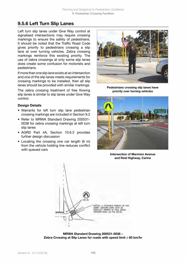
(Version 6 - 01/12/2016)
Planning and Designing for Pedestrians: Guidelines
166
9. Pedestrian Crossing Facilities
9.5.6 Left Turn Slip Lanes
Left turn slip lanes under Give Way control at signalised intersections may require crossing markings to ensure the safety of pedestrians. It should be noted that the Traffic Road Code gives priority to pedestrians crossing a slip lane at over turning vehicles. Zebra crossing markings reinforce this existing priority. The use of zebra crossings at only some slip lanes does create some confusion for motorists and pedestrians.
If more than one slip lane exists at an intersection and one of the slip lanes meets requirements for crossing markings to be installed, then all slip lanes should be provided with similar markings.
The zebra crossing treatment of free flowing slip lanes is similar to slip lanes under Give Way control.
Design Details• Warrants for left turn slip lane pedestrian
crossing markings are included in Section 9.2• Refer toMRWAStandardDrawing 200531-
0038 for zebra crossing markings at left turnslip lanes
• AGRD Part 4A, Section 10.6.3 providesfurther design discussion
• Locating the crossing one car length (6m)from the vehicle holding line reduces conflictwith queued cars
Pedestrians crossing slip lanes have priority over turning vehicles
\
Intersection of Marmion Avenue and Reid Highway, Carine
MRWA Standard Drawing 200531-0038 – Zebra Crossing at Slip Lanes for roads with speed limit ≤ 60 km/hr
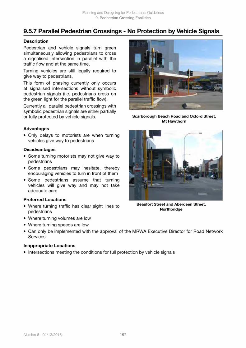
Planning and Designing for Pedestrians: Guidelines
167(Version 6 - 01/12/2016)
9. Pedestrian Crossing Facilities
9.5.7 Parallel Pedestrian Crossings - No Protection by Vehicle Signals
DescriptionPedestrian and vehicle signals turn green simultaneously allowing pedestrians to cross a signalised intersection in parallel with the traffic flow and at the same time.
Turning vehicles are still legally required to give way to pedestrians.
This form of phasing currently only occurs at signalised intersections without symbolic pedestrian signals (i.e. pedestrians cross on the green light for the parallel traffic flow).
Currently all parallel pedestrian crossings with symbolic pedestrian signals are either partially or fully protected by vehicle signals. Scarborough Beach Road and Oxford Street,
Mt Hawthorn
Advantages• Only delays to motorists are when turning
vehicles give way to pedestrians
Disadvantages • Someturningmotoristsmaynotgivewayto
pedestrians• Some pedestrians may hesitate, thereby
encouraging vehicles to turn in front of them• Some pedestrians assume that turning
vehicles will give way and may not takeadequate care
Preferred Locations• Where turning traffichasclearsight lines to
pedestrians
Beaufort Street and Aberdeen Street, Northbridge
• Whereturningvolumesarelow• Whereturningspeedsarelow• CanonlybeimplementedwiththeapprovaloftheMRWAExecutiveDirectorforRoadNetwork
Services
Inappropriate Locations• Intersectionsmeetingtheconditionsforfullprotectionbyvehiclesignals
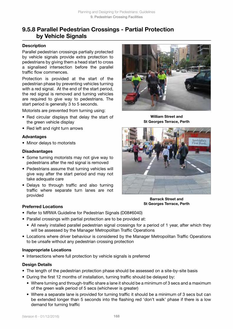
(Version 6 - 01/12/2016)
Planning and Designing for Pedestrians: Guidelines
168
9. Pedestrian Crossing Facilities
9.5.8 Parallel Pedestrian Crossings - Partial Protection by Vehicle Signals
DescriptionParallel pedestrian crossings partially protected by vehicle signals provide extra protection to pedestrians by giving them a head start to cross a signalised intersection before the parallel traffic flow commences.
Protection is provided at the start of the pedestrian phase by preventing vehicles turning with a red signal. At the end of the start period, the red signal is removed and turning vehicles are required to give way to pedestrians. The start period is generally 3 to 5 seconds.
Motorists are prevented from turning using:
• Red circular displays that delay the start ofthe green vehicle display
• Redleftandrightturnarrows
Advantages• Minordelaystomotorists
Disadvantages • Someturningmotoristsmaynotgivewayto
pedestrians after the red signal is removed• Pedestriansassumethatturningvehicleswill
give way after the start period and may nottake adequate care
• Delays to through traffic and also turningtraffic where separate turn lanes are notprovided
William Street and St Georges Terrace, Perth
Barrack Street and St Georges Terrace, Perth
Preferred Locations• RefertoMRWAGuidelineforPedestrianSignals(D08#6040)• Parallelcrossingswithpartialprotectionaretobeprovidedat:
• Allnewlyinstalledparallelpedestriansignalcrossingsforaperiodof1year,afterwhichtheywill be assessed by the Manager Metropolitan Traffic Operations
• LocationswheredriverbehaviourisconsideredbytheManagerMetropolitanTrafficOperationsto be unsafe without any pedestrian crossing protection
Inappropriate Locations• Intersectionswherefullprotectionbyvehiclesignalsispreferred
Design Details• Thelengthofthepedestrianprotectionphaseshouldbeassessedonasite-by-sitebasis• Duringthefirst12monthsofinstallation,turningtrafficshouldbedelayedby:
• Whereturningandthrough-trafficsharealaneitshouldbeaminimumof3secsandamaximumof the green walk period of 5 secs (whichever is greater)
• Whereaseparatelaneisprovidedforturningtrafficitshouldbeaminimumof3secsbutcanbe extended longer than 5 seconds into the flashing red ‘don’t walk’ phase if there is a lowdemand for turning traffic
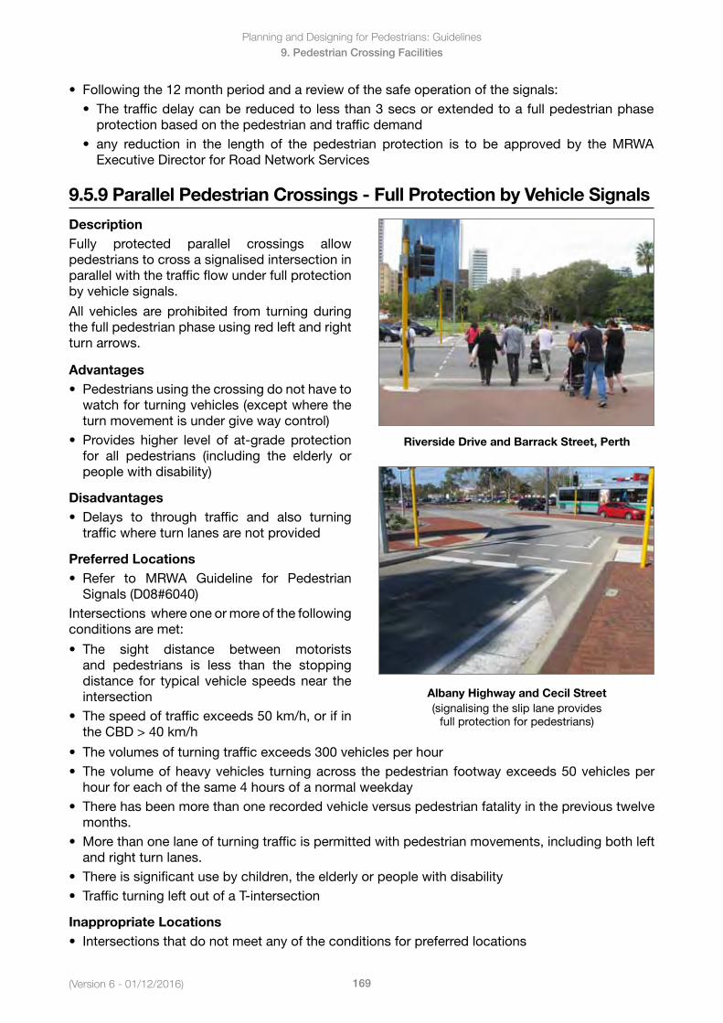
Planning and Designing for Pedestrians: Guidelines
169(Version 6 - 01/12/2016)
9. Pedestrian Crossing Facilities
• Followingthe12monthperiodandareviewofthesafeoperationofthesignals:• Thetrafficdelaycanbereducedtolessthan3secsorextendedtoafullpedestrianphase
protection based on the pedestrian and traffic demand• any reduction in the length of the pedestrian protection is to be approved by theMRWA
Executive Director for Road Network Services
9.5.9 Parallel Pedestrian Crossings - Full Protection by Vehicle Signals
DescriptionFully protected parallel crossings allow pedestrians to cross a signalised intersection in parallel with the traffic flow under full protection by vehicle signals.
All vehicles are prohibited from turning during the full pedestrian phase using red left and right turn arrows.
Advantages• Pedestriansusingthecrossingdonothaveto
watch for turning vehicles (except where theturn movement is under give way control)
• Provides higher level of at-grade protectionfor all pedestrians (including the elderly orpeople with disability)
Disadvantages • Delays to through traffic and also turning
traffic where turn lanes are not provided
Preferred Locations• Refer to MRWA Guideline for Pedestrian
Signals (D08#6040)Intersections where one or more of the following conditions are met:
• The sight distance between motoristsand pedestrians is less than the stoppingdistance for typical vehicle speeds near theintersection
• Thespeedoftrafficexceeds50km/h,orifintheCBD>40km/h
Riverside Drive and Barrack Street, Perth
Albany Highway and Cecil Street (signalising the slip lane provides
full protection for pedestrians)
• Thevolumesofturningtrafficexceeds300vehiclesperhour• Thevolumeofheavyvehicles turningacross thepedestrian footwayexceeds50vehiclesper
hour for each of the same 4 hours of a normal weekday• Therehasbeenmorethanonerecordedvehicleversuspedestrianfatalityintheprevioustwelve
months.• Morethanonelaneofturningtrafficispermittedwithpedestrianmovements,includingbothleft
and right turn lanes.• Thereissignificantusebychildren,theelderlyorpeoplewithdisability• TrafficturningleftoutofaT-intersection
Inappropriate Locations• Intersectionsthatdonotmeetanyoftheconditionsforpreferredlocations
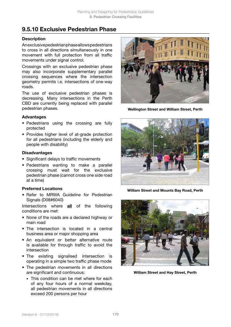
(Version 6 - 01/12/2016)
Planning and Designing for Pedestrians: Guidelines
170
9. Pedestrian Crossing Facilities
9.5.10 Exclusive Pedestrian Phase
DescriptionAn exclusive pedestrian phase allows pedestrians to cross in all directions simultaneously in one movement with full protection from all traffic movements under signal control.
Crossings with an exclusive pedestrian phase may also incorporate supplementary parallel crossing sequences where the intersection geometry permits i.e. intersections of one-way roads.
The use of exclusive pedestrian phases is decreasing. Many intersections in the Perth CBD are currently being replaced with parallel pedestrian phases.
Advantages• Pedestrians using the crossing are fully
protected• Provides higher level of at-grade protection
for all pedestrians (including the elderly andpeople with disability)
Disadvantages • Significantdelaystotrafficmovements• Pedestrians wanting to make a parallel
crossing must wait for the exclusivepedestrian phase (cannot cross one side roadat a time)
Preferred Locations• Refer to MRWA Guideline for Pedestrian
Signals (D08#6040)Intersections where all of the following conditions are met:
• Noneoftheroadsareadeclaredhighwayormain road
• The intersection is located in a centralbusiness area or major shopping area
• An equivalent or better alternative routeis available for through traffic to avoid theintersection
• The existing signalised intersection isoperating in a simple two traffic phase mode
• The pedestrian movements in all directionsare significant and continuous:• This condition can be met where for each
of any four hours of a normal weekday,all pedestrian movements in all directionsexceed 200 persons per hour
Wellington Street and William Street, Perth
William Street and Mounts Bay Road, Perth
William Street and Hay Street, Perth

Planning and Designing for Pedestrians: Guidelines
171(Version 6 - 01/12/2016)
9. Pedestrian Crossing Facilities
• Vehicular turning movements at the intersection are sufficiently high to impede reasonablepedestrian movement:• This condition can be met where for each of the same four hours of a normal week day, all
vehicular turning movements in all directions exceed 400 vehicles per hour
Inappropriate Locations• Intersectionsthatdonotmeetalltheconditionsforpreferredlocations
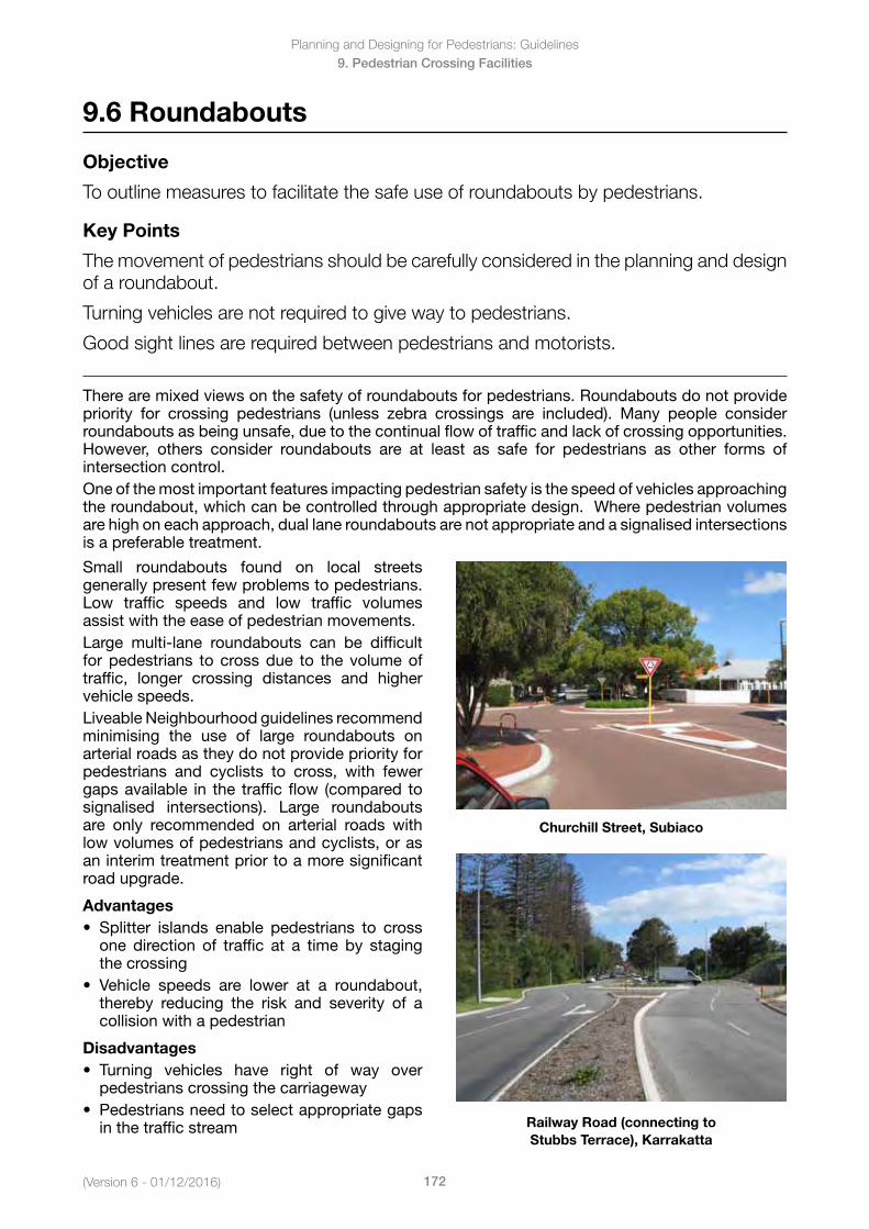
(Version 6 - 01/12/2016)
Planning and Designing for Pedestrians: Guidelines
172
9. Pedestrian Crossing Facilities
9.6 Roundabouts
Objective
To outline measures to facilitate the safe use of roundabouts by pedestrians.
Key Points
The movement of pedestrians should be carefully considered in the planning and design of a roundabout.
Turning vehicles are not required to give way to pedestrians.
Good sight lines are required between pedestrians and motorists.
There are mixed views on the safety of roundabouts for pedestrians. Roundabouts do not provide priority for crossing pedestrians (unless zebra crossings are included). Many people consider roundabouts as being unsafe, due to the continual flow of traffic and lack of crossing opportunities. However, others consider roundabouts are at least as safe for pedestrians as other forms ofintersection control.One of the most important features impacting pedestrian safety is the speed of vehicles approaching the roundabout, which can be controlled through appropriate design. Where pedestrian volumes are high on each approach, dual lane roundabouts are not appropriate and a signalised intersections is a preferable treatment.
Small roundabouts found on local streets generally present few problems to pedestrians. Low traffic speeds and low traffic volumes assist with the ease of pedestrian movements.Large multi-lane roundabouts can be difficult for pedestrians to cross due to the volume of traffic, longer crossing distances and higher vehicle speeds.Liveable Neighbourhood guidelines recommend minimising the use of large roundabouts on arterial roads as they do not provide priority for pedestrians and cyclists to cross, with fewer gaps available in the traffic flow (compared to signalised intersections). Large roundabouts are only recommended on arterial roads with low volumes of pedestrians and cyclists, or as an interim treatment prior to a more significant road upgrade.
Advantages• Splitter islands enable pedestrians to cross
one direction of traffic at a time by staging the crossing
• Vehicle speeds are lower at a roundabout,thereby reducing the risk and severity of a collision with a pedestrian
Disadvantages• Turning vehicles have right of way over
pedestrians crossing the carriageway• Pedestriansneedtoselectappropriategaps
in the traffic stream
Churchill Street, Subiaco
Railway Road (connecting to Stubbs Terrace), Karrakatta
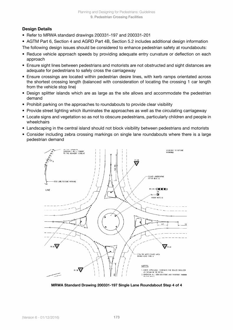
Planning and Designing for Pedestrians: Guidelines
173(Version 6 - 01/12/2016)
9. Pedestrian Crossing Facilities
Design Details• RefertoMRWAstandarddrawings200331-197and200331-201• AGTMPart6,Section4andAGRDPart4B,Section5.2includesadditionaldesigninformationThe following design issues should be considered to enhance pedestrian safety at roundabouts:
• Reducevehicleapproachspeedsbyprovidingadequateentrycurvatureordeflectiononeachapproach
• Ensuresightlinesbetweenpedestriansandmotoristsarenotobstructedandsightdistancesareadequate for pedestrians to safely cross the carriageway
• Ensurecrossingsarelocatedwithinpedestriandesirelines,withkerbrampsorientatedacrossthe shortest crossing length (balanced with consideration of locating the crossing 1 car lengthfrom the vehicle stop line)
• Designsplitter islandswhichareas largeasthesiteallowsandaccommodatethepedestriandemand
• Prohibitparkingontheapproachestoroundaboutstoprovideclearvisibility• Providestreetlightingwhichilluminatestheapproachesaswellasthecirculatingcarriageway• Locatesignsandvegetationsoasnottoobscurepedestrians,particularlychildrenandpeoplein
wheelchairs• Landscapinginthecentralislandshouldnotblockvisibilitybetweenpedestriansandmotorists• Considerincludingzebracrossingmarkingsonsinglelaneroundaboutswherethereisalarge
pedestrian demand
MRWA Standard Drawing 200331-197 Single Lane Roundabout Step 4 of 4
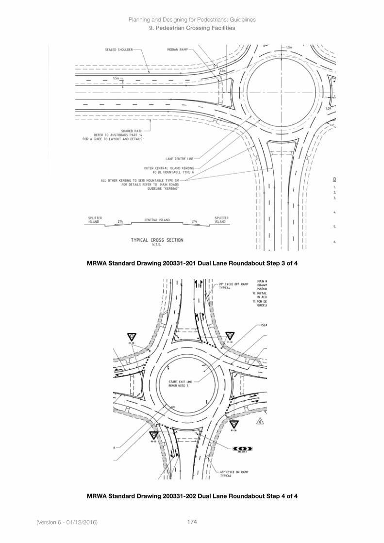
(Version 6 - 01/12/2016)
Planning and Designing for Pedestrians: Guidelines
174
9. Pedestrian Crossing Facilities
MRWA Standard Drawing 200331-201 Dual Lane Roundabout Step 3 of 4
MRWA Standard Drawing 200331-202 Dual Lane Roundabout Step 4 of 4
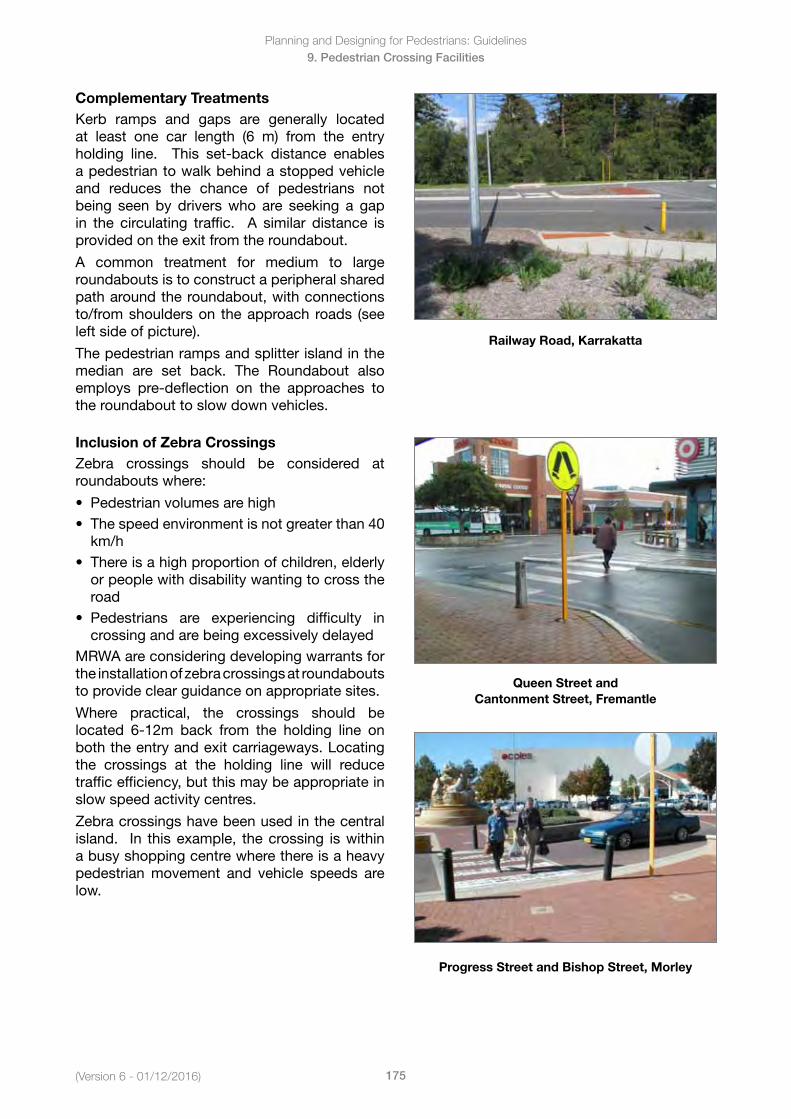
Planning and Designing for Pedestrians: Guidelines
175(Version 6 - 01/12/2016)
9. Pedestrian Crossing Facilities
Complementary TreatmentsKerb ramps and gaps are generally located at least one car length (6 m) from the entry holding line. This set-back distance enables a pedestrian to walk behind a stopped vehicle and reduces the chance of pedestrians not being seen by drivers who are seeking a gap in the circulating traffic. A similar distance is provided on the exit from the roundabout.
A common treatment for medium to large roundabouts is to construct a peripheral shared path around the roundabout, with connections to/from shoulders on the approach roads (see left side of picture).
The pedestrian ramps and splitter island in the median are set back. The Roundabout also employs pre-deflection on the approaches to the roundabout to slow down vehicles.
Railway Road, Karrakatta
Inclusion of Zebra CrossingsZebra crossings should be considered at roundabouts where:
• Pedestrianvolumesarehigh• Thespeedenvironmentisnotgreaterthan40
km/h• Thereisahighproportionofchildren,elderly
or people with disability wanting to cross theroad
• Pedestrians are experiencing difficulty incrossing and are being excessively delayed
MRWA are considering developing warrants for the installation of zebra crossings at roundabouts to provide clear guidance on appropriate sites.
Where practical, the crossings should be located 6-12m back from the holding line on both the entry and exit carriageways. Locating the crossings at the holding line will reduce traffic efficiency, but this may be appropriate in slow speed activity centres.
Zebra crossings have been used in the central island. In this example, the crossing is within a busy shopping centre where there is a heavy pedestrian movement and vehicle speeds are low.
Queen Street and Cantonment Street, Fremantle
Progress Street and Bishop Street, Morley
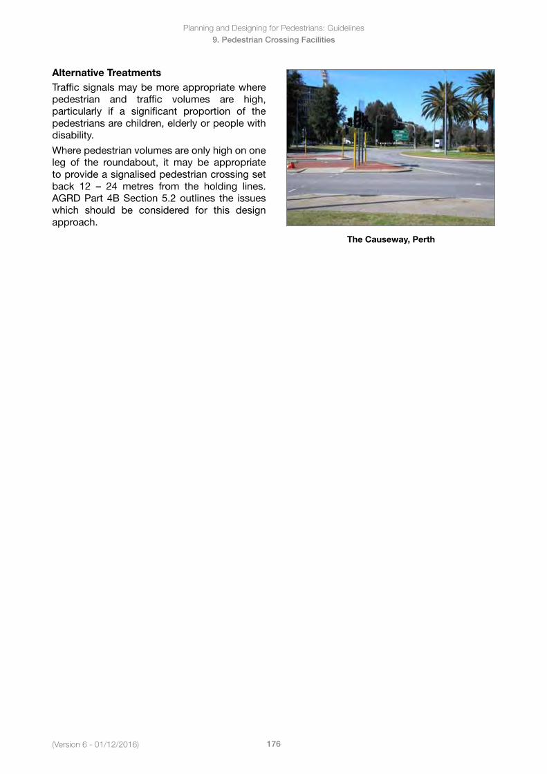
(Version 6 - 01/12/2016)
Planning and Designing for Pedestrians: Guidelines
176
9. Pedestrian Crossing Facilities
Alternative TreatmentsTraffic signals may be more appropriate where pedestrian and traffic volumes are high, particularly if a significant proportion of the pedestrians are children, elderly or people with disability.
Where pedestrian volumes are only high on one leg of the roundabout, it may be appropriate to provide a signalised pedestrian crossing set back 12 – 24 metres from the holding lines.AGRD Part 4B Section 5.2 outlines the issues which should be considered for this design approach.
The Causeway, Perth
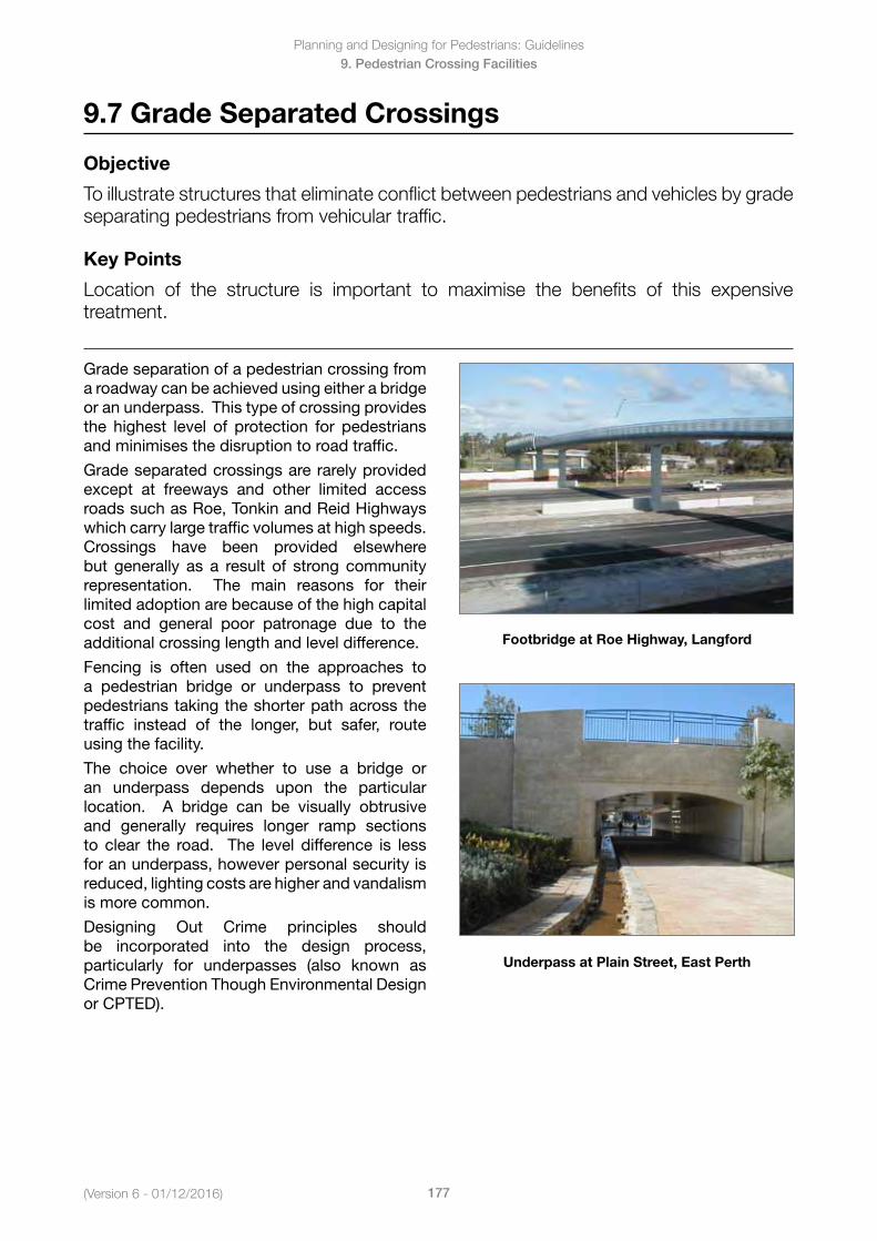
Planning and Designing for Pedestrians: Guidelines
177(Version 6 - 01/12/2016)
9. Pedestrian Crossing Facilities
9.7 Grade Separated Crossings
Objective
To illustrate structures that eliminate conflict between pedestrians and vehicles by grade separating pedestrians from vehicular traffic.
Key Points
Location of the structure is important to maximise the benefits of this expensive treatment.
Grade separation of a pedestrian crossing from a roadway can be achieved using either a bridge or an underpass. This type of crossing provides the highest level of protection for pedestrians and minimises the disruption to road traffic.
Grade separated crossings are rarely provided except at freeways and other limited access roadssuchasRoe,TonkinandReidHighwayswhich carry large traffic volumes at high speeds. Crossings have been provided elsewhere but generally as a result of strong community representation. The main reasons for their limited adoption are because of the high capital cost and general poor patronage due to the additional crossing length and level difference.
Fencing is often used on the approaches to a pedestrian bridge or underpass to prevent pedestrians taking the shorter path across the traffic instead of the longer, but safer, route using the facility.
The choice over whether to use a bridge or an underpass depends upon the particular location. A bridge can be visually obtrusive and generally requires longer ramp sections to clear the road. The level difference is less for an underpass, however personal security is reduced, lighting costs are higher and vandalism is more common.
Designing Out Crime principles should be incorporated into the design process, particularly for underpasses (also known as Crime Prevention Though Environmental Design or CPTED).
Footbridge at Roe Highway, Langford
Underpass at Plain Street, East Perth
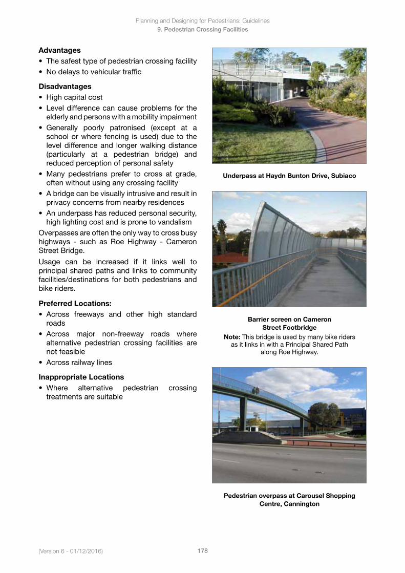
(Version 6 - 01/12/2016)
Planning and Designing for Pedestrians: Guidelines
178
9. Pedestrian Crossing Facilities
Advantages• Thesafesttypeofpedestriancrossingfacility• Nodelaystovehiculartraffic
Disadvantages• Highcapitalcost• Leveldifferencecancauseproblemsforthe
elderly and persons with a mobility impairment• Generally poorly patronised (except at a
school or where fencing is used) due to thelevel difference and longer walking distance(particularly at a pedestrian bridge) andreduced perception of personal safety
• Many pedestrians prefer to cross at grade,often without using any crossing facility
• Abridgecanbevisuallyintrusiveandresultinprivacy concerns from nearby residences
• Anunderpasshasreducedpersonalsecurity,high lighting cost and is prone to vandalism
Overpasses are often the only way to cross busy highways - such as Roe Highway - CameronStreet Bridge.
Usage can be increased if it links well to principal shared paths and links to community facilities/destinations for both pedestrians and bike riders.
Preferred Locations:• Across freeways and other high standard
roads• Across major non-freeway roads where
alternative pedestrian crossing facilities arenot feasible
• Acrossrailwaylines
Inappropriate Locations• Where alternative pedestrian crossing
treatments are suitable
Underpass at Haydn Bunton Drive, Subiaco
Barrier screen on Cameron Street Footbridge
Note: This bridge is used by many bike riders as it links in with a Principal Shared Path
alongRoeHighway.
Pedestrian overpass at Carousel Shopping Centre, Cannington
Planning and Designing for Pedestrians: Guidelines
179(Version 6 - 01/12/2016)
9. Pedestrian Crossing Facilities
Design Details• AGTMPart6Table8.1andAGRDPart4CSection4.4includeabriefdiscussionofconsiderations
for grade separated crossings• AS5100.1–2004Clause9.1andClause12includedesigninformationforpedestrianbridges• Bridgesandunderpassesmustbeaccessibleforpedestrianswithdisability:
• Informationonrampgradients,TGSIandbalustradesisincludedinSection7.6and7.9• Toencouragepatronageofgradeseparatedfacilities:
• Themaximumchangeinlevelforoverpassesshouldbeabout6.5m• Themaximumchangeinlevelforunderpassesshouldbeabout3.5m,withpedestriansable
to see along the length of the underpass• Overheadclearancewithinthestructuremustallowforsafepedestrianandcyclistpassage:• Minimum clearance of 2.5 m for routes used by pedestrians and cyclists (Refer to Section 7.4)
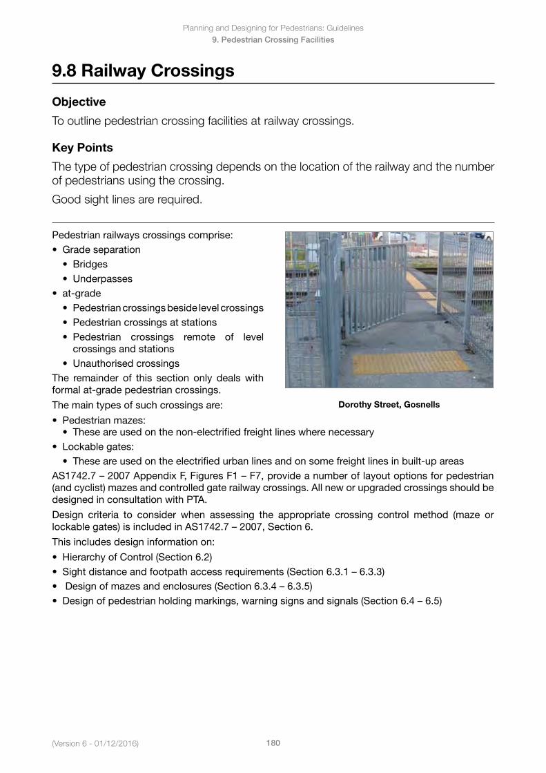
(Version 6 - 01/12/2016)
Planning and Designing for Pedestrians: Guidelines
180
9. Pedestrian Crossing Facilities
9.8 Railway Crossings
Objective
To outline pedestrian crossing facilities at railway crossings.
Key Points
The type of pedestrian crossing depends on the location of the railway and the number of pedestrians using the crossing.
Good sight lines are required.
Pedestrian railways crossings comprise:• Gradeseparation
• Bridges• Underpasses
• at-grade• Pedestriancrossingsbesidelevelcrossings• Pedestriancrossingsatstations• Pedestrian crossings remote of level
crossings and stations• Unauthorisedcrossings
The remainder of this section only deals with formal at-grade pedestrian crossings.
The main types of such crossings are:
• Pedestrianmazes:
Dorothy Street, Gosnells
• These are used on the non-electrified freight lines where necessary• Lockablegates:
• Theseareusedontheelectrifiedurbanlinesandonsomefreightlinesinbuilt-upareasAS1742.7–2007AppendixF,FiguresF1–F7,provideanumberoflayoutoptionsforpedestrian(and cyclist) mazes and controlled gate railway crossings. All new or upgraded crossings should be designed in consultation with PTA.
Design criteria to consider when assessing the appropriate crossing control method (maze or lockablegates)isincludedinAS1742.7–2007,Section6.
This includes design information on:
• HierarchyofControl(Section6.2)• Sightdistanceandfootpathaccessrequirements(Section6.3.1–6.3.3)• Designofmazesandenclosures(Section6.3.4–6.3.5)• Designofpedestrianholdingmarkings,warningsignsandsignals(Section6.4–6.5)
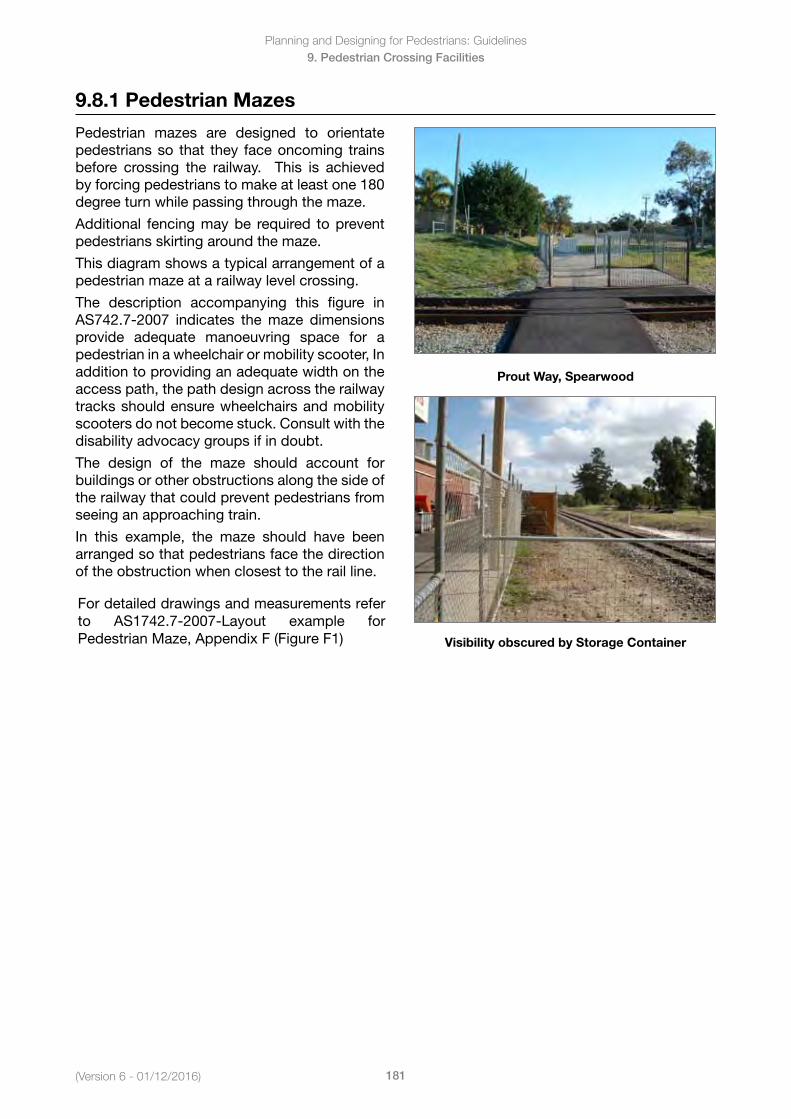
Planning and Designing for Pedestrians: Guidelines
181(Version 6 - 01/12/2016)
9. Pedestrian Crossing Facilities
9.8.1 Pedestrian Mazes
Pedestrian mazes are designed to orientate pedestrians so that they face oncoming trains before crossing the railway. This is achieved by forcing pedestrians to make at least one 180 degree turn while passing through the maze.
Additional fencing may be required to prevent pedestrians skirting around the maze.
This diagram shows a typical arrangement of a pedestrian maze at a railway level crossing.
The description accompanying this figure in AS742.7-2007 indicates the maze dimensions provide adequate manoeuvring space for a pedestrian in a wheelchair or mobility scooter, In addition to providing an adequate width on the access path, the path design across the railway tracks should ensure wheelchairs and mobility scooters do not become stuck. Consult with the disability advocacy groups if in doubt.
The design of the maze should account for buildings or other obstructions along the side of the railway that could prevent pedestrians from seeing an approaching train.
In this example, the maze should have been arranged so that pedestrians face the direction of the obstruction when closest to the rail line.
Prout Way, Spearwood
Visibility obscured by Storage Container
For detailed drawings and measurements refer to AS1742.7-2007-Layout example for Pedestrian Maze, Appendix F (Figure F1)
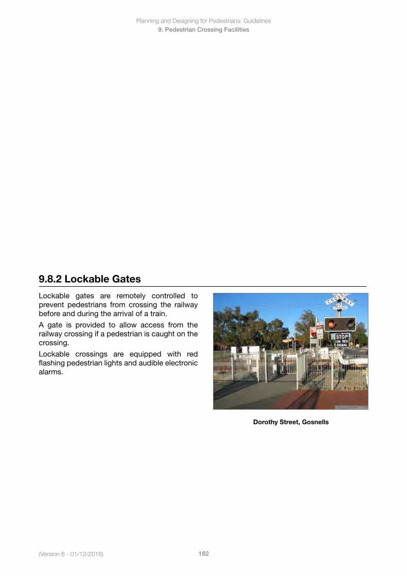
(Version 6 - 01/12/2016)
Planning and Designing for Pedestrians: Guidelines
182
9. Pedestrian Crossing Facilities
9.8.2 Lockable Gates
Lockable gates are remotely controlled to prevent pedestrians from crossing the railway before and during the arrival of a train.
A gate is provided to allow access from the railway crossing if a pedestrian is caught on the crossing.
Lockable crossings are equipped with red flashing pedestrian lights and audible electronic alarms.
Dorothy Street, Gosnells
Planning and Designing for Pedestrians: Guidelines
183(Version 6 - 01/12/2016)
10. Pedestrian Guidance Measures
10. Pedestrian Guidance Measures
In this Section
10.1 Lighting
10.1.1 Critical Areas of illumination
10.1.2 Pedestrian Crossings
10.1.3 Pedestrian and Cyclist Pathways
10.1.4 Underpasses and Tunnels
10.1.5 Location of Lights
10.2 Directional, Service and Tourist Signs
10.2.1 Location
10.2.2 Direction Signs
10.2.3 Visibility
10.2.4 Legibility
10.2.5 Font
10.2.6 Colour Contrast
10.2.7 Glare and Reflective Surfaces
10.2.8 Pavement Markings
10.3 Pedestrian Warning Signs
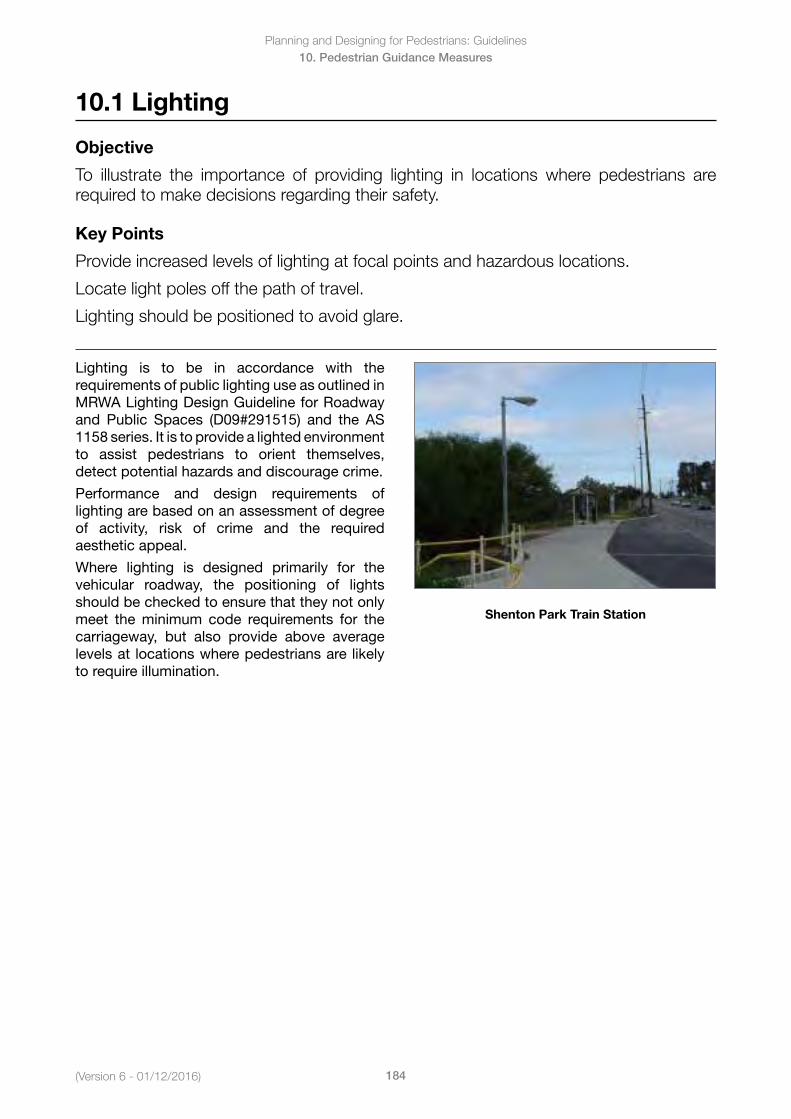
(Version 6 - 01/12/2016)
Planning and Designing for Pedestrians: Guidelines
184
10. Pedestrian Guidance Measures
10.1 Lighting
Objective
To illustrate the importance of providing lighting in locations where pedestrians are required to make decisions regarding their safety.
Key Points
Provide increased levels of lighting at focal points and hazardous locations.
Locate light poles off the path of travel.
Lighting should be positioned to avoid glare.
Lighting is to be in accordance with the requirements of public lighting use as outlined in MRWA Lighting Design Guideline for Roadway and Public Spaces (D09#291515) and the AS 1158 series. It is to provide a lighted environment to assist pedestrians to orient themselves, detect potential hazards and discourage crime.
Performance and design requirements of lighting are based on an assessment of degree of activity, risk of crime and the required aesthetic appeal.
Where lighting is designed primarily for the vehicular roadway, the positioning of lights should be checked to ensure that they not only meet the minimum code requirements for the carriageway, but also provide above average levels at locations where pedestrians are likely to require illumination.
Shenton Park Train Station
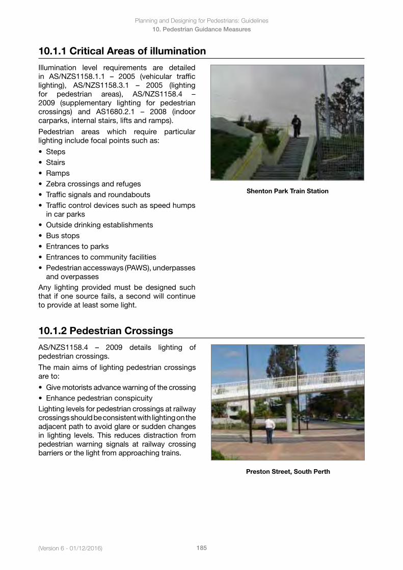
Planning and Designing for Pedestrians: Guidelines
185(Version 6 - 01/12/2016)
10. Pedestrian Guidance Measures
10.1.1 Critical Areas of illumination
Illumination level requirements are detailed in AS/NZS1158.1.1 – 2005 (vehicular trafficlighting), AS/NZS1158.3.1 – 2005 (lightingfor pedestrian areas), AS/NZS1158.4 –2009 (supplementary lighting for pedestrian crossings) and AS1680.2.1 – 2008 (indoorcarparks, internal stairs, lifts and ramps).
Pedestrian areas which require particular lighting include focal points such as:
• Steps• Stairs• Ramps• Zebracrossingsandrefuges• Trafficsignalsandroundabouts• Trafficcontroldevicessuchasspeedhumps
in car parks• Outsidedrinkingestablishments• Busstops• Entrancestoparks• Entrancestocommunityfacilities• Pedestrianaccessways(PAWS),underpasses
and overpassesAny lighting provided must be designed such that if one source fails, a second will continue to provide at least some light.
Shenton Park Train Station
10.1.2 Pedestrian Crossings
AS/NZS1158.4 – 2009 details lighting ofpedestrian crossings.
The main aims of lighting pedestrian crossings are to:
• Givemotoristsadvancewarningofthecrossing• EnhancepedestrianconspicuityLighting levels for pedestrian crossings at railway crossings should be consistent with lighting on the adjacent path to avoid glare or sudden changes in lighting levels. This reduces distraction from pedestrian warning signals at railway crossing barriers or the light from approaching trains.
Preston Street, South Perth
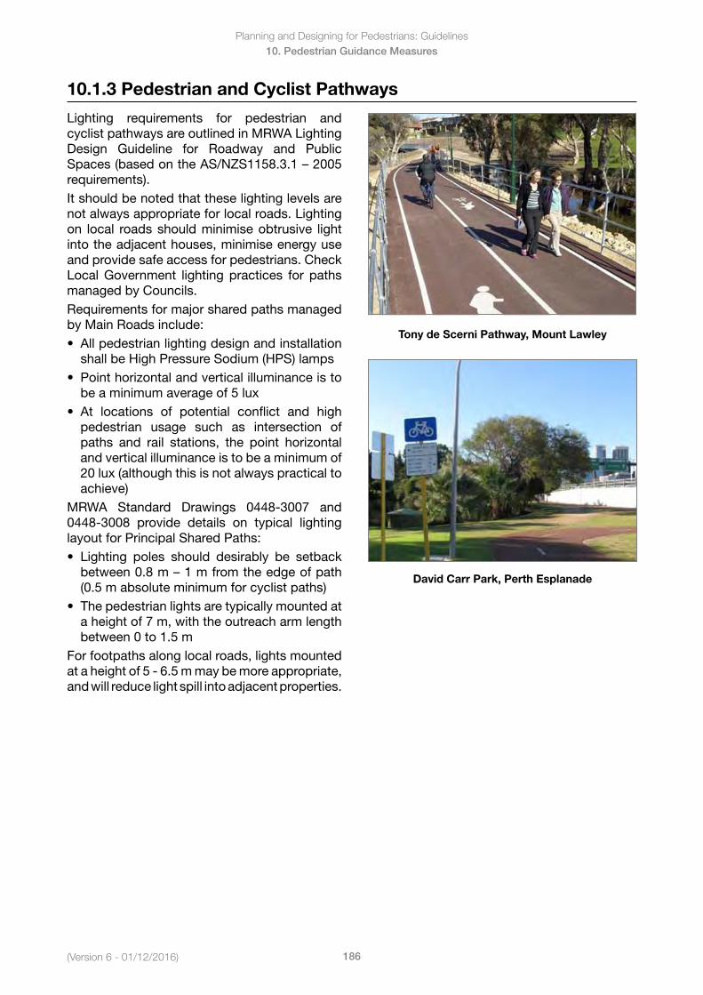
(Version 6 - 01/12/2016)
Planning and Designing for Pedestrians: Guidelines
186
10. Pedestrian Guidance Measures
10.1.3 Pedestrian and Cyclist Pathways
Lighting requirements for pedestrian and cyclist pathways are outlined in MRWA Lighting Design Guideline for Roadway and Public Spaces(basedontheAS/NZS1158.3.1–2005requirements). It should be noted that these lighting levels are not always appropriate for local roads. Lighting on local roads should minimise obtrusive light into the adjacent houses, minimise energy use and provide safe access for pedestrians. Check Local Government lighting practices for paths managed by Councils.Requirements for major shared paths managed by Main Roads include:• Allpedestrianlightingdesignandinstallation
shallbeHighPressureSodium(HPS)lamps• Pointhorizontalandverticalilluminanceisto
be a minimum average of 5 lux• At locations of potential conflict and high
pedestrian usage such as intersection ofpaths and rail stations, the point horizontaland vertical illuminance is to be a minimum of20 lux (although this is not always practical toachieve)
MRWA Standard Drawings 0448-3007 and 0448-3008 provide details on typical lighting layout for Principal Shared Paths:• Lighting poles should desirably be setback
between0.8m–1mfromtheedgeofpath(0.5 m absolute minimum for cyclist paths)
• Thepedestrianlightsaretypicallymountedata height of 7 m, with the outreach arm lengthbetween 0 to 1.5 m
For footpaths along local roads, lights mounted at a height of 5 - 6.5 m may be more appropriate, and will reduce light spill into adjacent properties.
Tony de Scerni Pathway, Mount Lawley
David Carr Park, Perth Esplanade
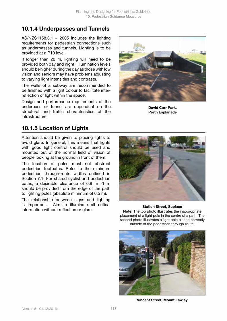
Planning and Designing for Pedestrians: Guidelines
187(Version 6 - 01/12/2016)
10. Pedestrian Guidance Measures
10.1.4 Underpasses and Tunnels
AS/NZS1158.3.1 – 2005 includes the lightingrequirements for pedestrian connections such as underpasses and tunnels. Lighting is to be provided at a P10 level.
If longer than 20 m, lighting will need to be provided both day and night. Illumination levels should be higher during the day as those with low vision and seniors may have problems adjusting to varying light intensities and contrasts.
The walls of a subway are recommended to be finished with a light colour to facilitate inter-reflection of light within the space.
Design and performance requirements of the underpass or tunnel are dependent on the structural and traffic characteristics of the infrastructure.
David Carr Park, Perth Esplanade
10.1.5 Location of Lights
Attention should be given to placing lights to avoid glare. In general, this means that lights with good light control should be used and mounted out of the normal field of vision of people looking at the ground in front of them.
The location of poles must not obstruct pedestrian footpaths. Refer to the minimum pedestrian through-route widths outlined in Section 7.1. For shared cyclist and pedestrian paths, a desirable clearance of 0.8 m -1 m should be provided from the edge of the path to lighting poles (absolute minimum of 0.5 m).
The relationship between signs and lighting is important. Aim to illuminate all critical information without reflection or glare.
Station Street, SubiacoNote: The top photo illustrates the inappropriate
placement of a light pole in the centre of a path. The second photo illustrates a light pole placed correctly
outside of the pedestrian through-route.
Vincent Street, Mount Lawley
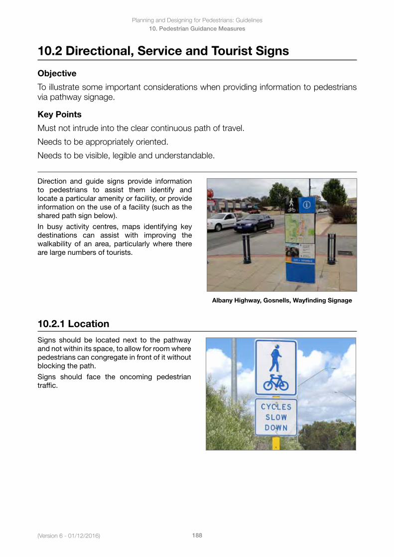
(Version 6 - 01/12/2016)
Planning and Designing for Pedestrians: Guidelines
188
10. Pedestrian Guidance Measures
10.2 Directional, Service and Tourist Signs
Objective
To illustrate some important considerations when providing information to pedestrians via pathway signage.
Key Points
Must not intrude into the clear continuous path of travel.
Needs to be appropriately oriented.
Needs to be visible, legible and understandable.
Direction and guide signs provide information to pedestrians to assist them identify and locate a particular amenity or facility, or provide information on the use of a facility (such as the shared path sign below).
In busy activity centres, maps identifying key destinations can assist with improving the walkability of an area, particularly where there are large numbers of tourists.
Albany Highway, Gosnells, Wayfinding Signage
10.2.1 Location
Signs should be located next to the pathway and not within its space, to allow for room where pedestrians can congregate in front of it without blocking the path.
Signs should face the oncoming pedestrian traffic.
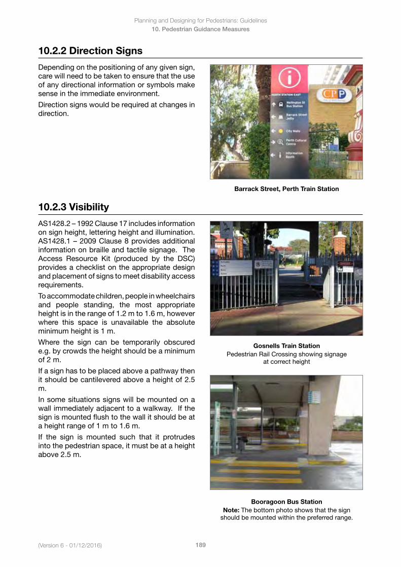
Planning and Designing for Pedestrians: Guidelines
189(Version 6 - 01/12/2016)
10. Pedestrian Guidance Measures
10.2.2 Direction Signs
Depending on the positioning of any given sign, care will need to be taken to ensure that the use of any directional information or symbols make sense in the immediate environment.
Direction signs would be required at changes in direction.
Barrack Street, Perth Train Station
10.2.3 Visibility
AS1428.2–1992Clause17includesinformationon sign height, lettering height and illumination. AS1428.1–2009Clause8providesadditionalinformation on braille and tactile signage. The Access Resource Kit (produced by the DSC) provides a checklist on the appropriate design and placement of signs to meet disability access requirements.
To accommodate children, people in wheelchairs and people standing, the most appropriate height is in the range of 1.2 m to 1.6 m, however where this space is unavailable the absolute minimum height is 1 m.
Where the sign can be temporarily obscured e.g. by crowds the height should be a minimum of 2 m.
If a sign has to be placed above a pathway then it should be cantilevered above a height of 2.5 m.
In some situations signs will be mounted on a wall immediately adjacent to a walkway. If the sign is mounted flush to the wall it should be at a height range of 1 m to 1.6 m.
If the sign is mounted such that it protrudes into the pedestrian space, it must be at a height above 2.5 m.
Gosnells Train Station Pedestrian Rail Crossing showing signage
at correct height
Booragoon Bus StationNote: The bottom photo shows that the sign
should be mounted within the preferred range.
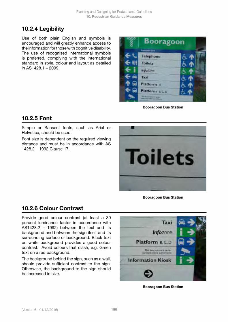
(Version 6 - 01/12/2016)
Planning and Designing for Pedestrians: Guidelines
190
10. Pedestrian Guidance Measures
10.2.4 Legibility
Use of both plain English and symbols is encouraged and will greatly enhance access to the information for those with cognitive disability. The use of recognised international symbols is preferred, complying with the international standard in style, colour and layout as detailed inAS1428.1–2009.
Booragoon Bus Station
10.2.5 Font
Simple or Sanserif fonts, such as Arial or Helvetica,shouldbeused.
Font size is dependent on the required viewing distance and must be in accordance with AS 1428.2–1992Clause17.
Booragoon Bus Station
10.2.6 Colour Contrast
Provide good colour contrast (at least a 30 percent luminance factor in accordance with AS1428.2 – 1992) between the text and itsbackground and between the sign itself and its surrounding surface or background. Black text on white background provides a good colour contrast. Avoid colours that clash, e.g. Green text on a red background.
The background behind the sign, such as a wall, should provide sufficient contrast to the sign. Otherwise, the background to the sign should be increased in size.
Booragoon Bus Station
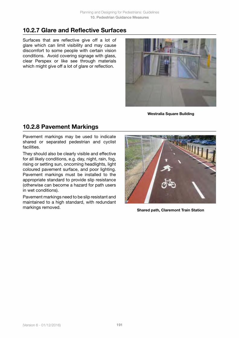
Planning and Designing for Pedestrians: Guidelines
191(Version 6 - 01/12/2016)
10. Pedestrian Guidance Measures
10.2.7 Glare and Reflective Surfaces
Surfaces that are reflective give off a lot of glare which can limit visibility and may cause discomfort to some people with certain vision conditions. Avoid covering signage with glass, clear Perspex or like see through materials which might give off a lot of glare or reflection.
Westralia Square Building
10.2.8 Pavement Markings
Pavement markings may be used to indicate shared or separated pedestrian and cyclist facilities.
They should also be clearly visible and effective for all likely conditions, e.g. day, night, rain, fog, rising or setting sun, oncoming headlights, light coloured pavement surface, and poor lighting. Pavement markings must be installed to the appropriate standard to provide slip resistance (otherwise can become a hazard for path users in wet conditions).
Pavement markings need to be slip resistant and maintained to a high standard, with redundant markings removed.
Shared path, Claremont Train Station
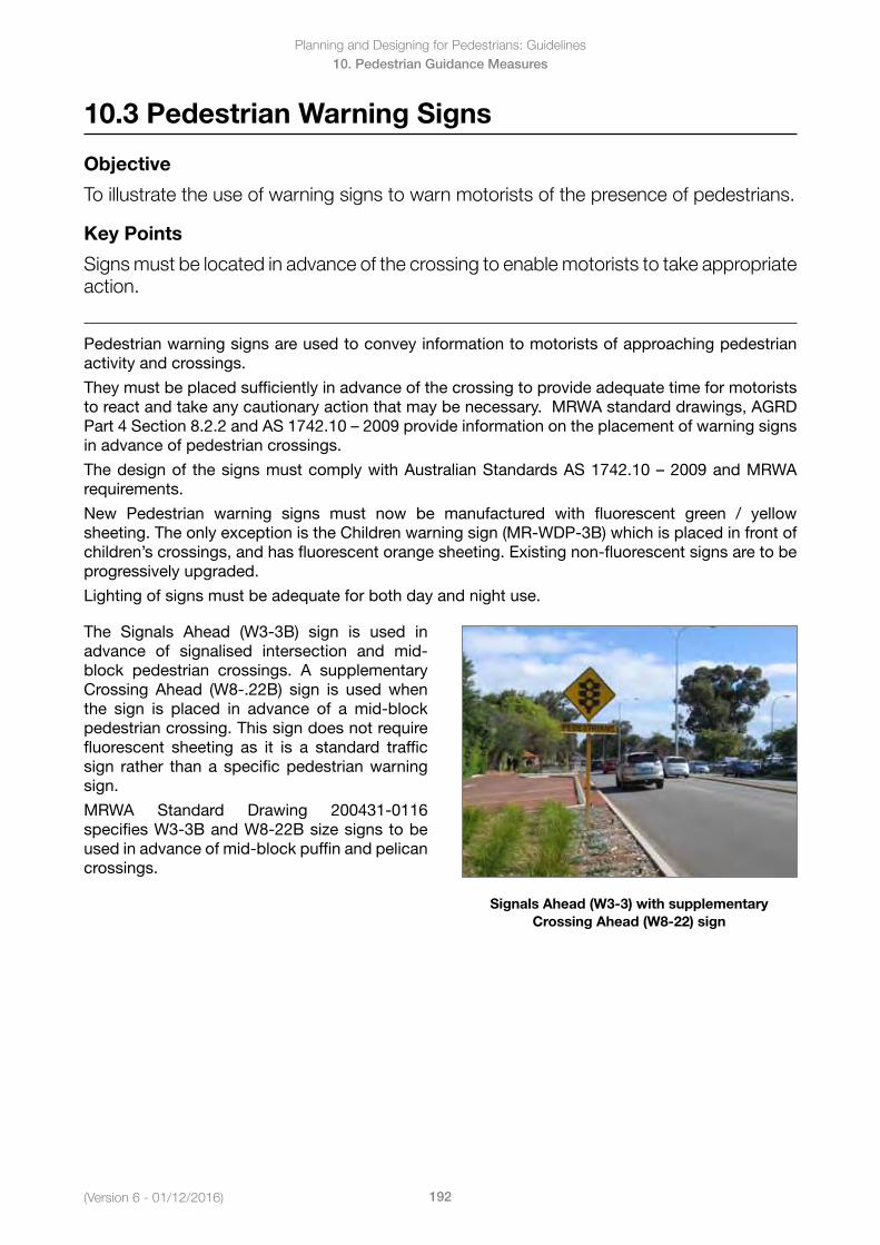
(Version 6 - 01/12/2016)
Planning and Designing for Pedestrians: Guidelines
192
10. Pedestrian Guidance Measures
10.3 Pedestrian Warning Signs
Objective
To illustrate the use of warning signs to warn motorists of the presence of pedestrians.
Key Points
Signs must be located in advance of the crossing to enable motorists to take appropriate action.
Pedestrian warning signs are used to convey information to motorists of approaching pedestrian activity and crossings.
They must be placed sufficiently in advance of the crossing to provide adequate time for motorists to react and take any cautionary action that may be necessary. MRWA standard drawings, AGRD Part4Section8.2.2andAS1742.10–2009provideinformationontheplacementofwarningsignsin advance of pedestrian crossings.
Thedesignof thesignsmustcomplywithAustralianStandardsAS1742.10–2009andMRWArequirements.
New Pedestrian warning signs must now be manufactured with fluorescent green / yellow sheeting. The only exception is the Children warning sign (MR-WDP-3B) which is placed in front of children’s crossings, and has fluorescent orange sheeting. Existing non-fluorescent signs are to be progressively upgraded.
Lighting of signs must be adequate for both day and night use.
The Signals Ahead (W3-3B) sign is used in advance of signalised intersection and mid-block pedestrian crossings. A supplementary Crossing Ahead (W8-.22B) sign is used when the sign is placed in advance of a mid-block pedestrian crossing. This sign does not require fluorescent sheeting as it is a standard traffic sign rather than a specific pedestrian warning sign.
MRWA Standard Drawing 200431-0116 specifies W3-3B and W8-22B size signs to be used in advance of mid-block puffin and pelican crossings.
Signals Ahead (W3-3) with supplementary Crossing Ahead (W8-22) sign
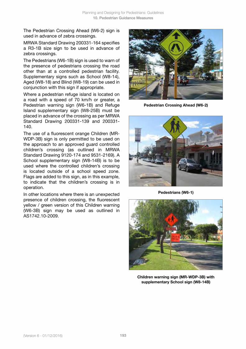
Planning and Designing for Pedestrians: Guidelines
193(Version 6 - 01/12/2016)
10. Pedestrian Guidance Measures
The Pedestrian Crossing Ahead (W6-2) sign is used in advance of zebra crossings.
MRWA Standard Drawing 200331-164 specifies a R3-1B size sign to be used in advance of zebra crossings.
The Pedestrians (W6-1B) sign is used to warn of the presence of pedestrians crossing the road other than at a controlled pedestrian facility. Supplementary signs such as School (W8-14), Aged (W8-18) and Blind (W8-19) can be used in conjunction with this sign if appropriate.
Where a pedestrian refuge island is located on a road with a speed of 70 km/h or greater, a Pedestrian warning sign (W6-1B) and Refuge Island supplementary sign (W8-25B) must be placed in advance of the crossing as per MRWA Standard Drawing 200331-139 and 200331-140.
The use of a fluorescent orange Children (MR-WDP-3B) sign is only permitted to be used on the approach to an approved guard controlled children’s crossing (as outlined in MRWA Standard Drawing 9120-174 and 9531-2169). A School supplementary sign (W8-14B) is to be used where the controlled children’s crossing is located outside of a school speed zone. Flags are added to this sign, as in this example, to indicate that the children’s crossing is in operation.
In other locations where there is an unexpected presence of children crossing, the fluorescent yellow / green version of this Children warning (W6-3B) sign may be used as outlined in AS1742.10-2009.
Pedestrian Crossing Ahead (W6-2)
Pedestrians (W6-1)
Children warning sign (MR-WDP-3B) with supplementary School sign (W8-14B)
Planning and Designing for Pedestrians: Guidelines
194(Version 6- 01/12/2016)
11. Speed and Environmental Changes
11. Speed and Environmental Changes
In this Section
11.1 School Speed Zones
11.1.1 Speed Limits
11.1.2 Times of Operation
11.1.3 Selection Criteria
11.1.4 Length of School Zone
11.1.5 Signs and Pavement Markings
11.2 Variable Speed Zones
11.2.1 Design and Approval
11.2.2 Examples
11.3 Shared Zones
11.3.1 Criteria
11.3.2 Roadways and Parking
11.3.3 Traffic Calming in Shared Zones
11.3.4 Signs
11.4 Traffic Calming
11.4.1 Traffic Management in Activity Centres
11.4.2 Physical and Regulatory Techniques
11.4.3 Precautions
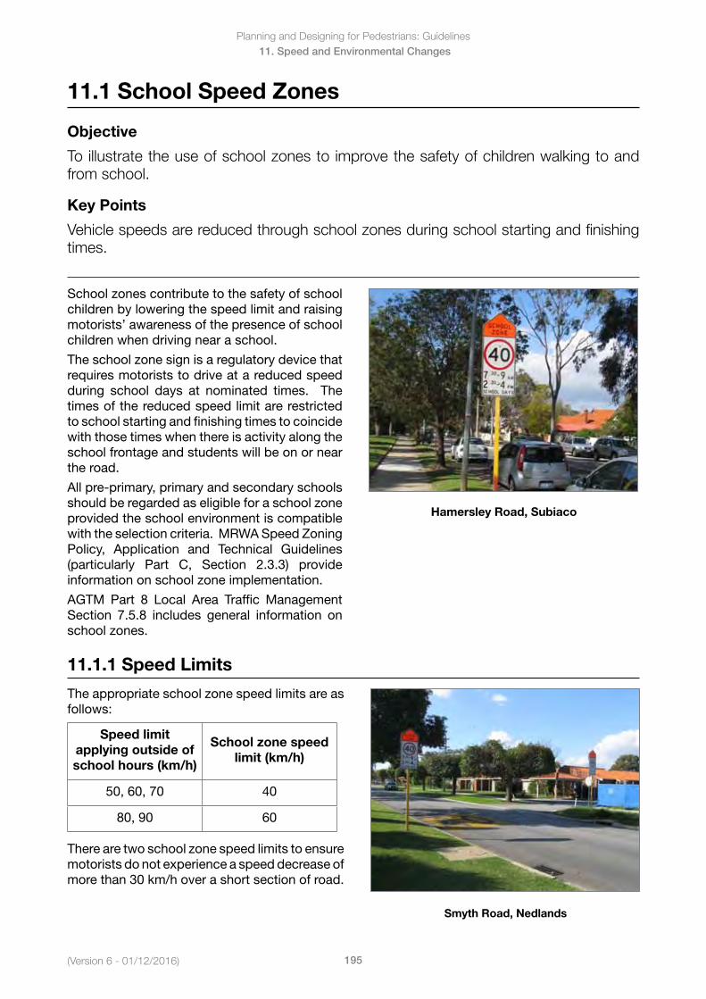
(Version 6 - 01/12/2016)
Planning and Designing for Pedestrians: Guidelines
195
11. Speed and Environmental Changes
11.1 School Speed Zones
Objective
To illustrate the use of school zones to improve the safety of children walking to and from school.
Key Points
Vehicle speeds are reduced through school zones during school starting and finishing times.
School zones contribute to the safety of school children by lowering the speed limit and raising motorists’ awareness of the presence of school children when driving near a school.
The school zone sign is a regulatory device that requires motorists to drive at a reduced speed during school days at nominated times. The times of the reduced speed limit are restricted to school starting and finishing times to coincide with those times when there is activity along the school frontage and students will be on or near the road.
All pre-primary, primary and secondary schools should be regarded as eligible for a school zone provided the school environment is compatible with the selection criteria. MRWA Speed Zoning Policy, Application and Technical Guidelines (particularly Part C, Section 2.3.3) provide information on school zone implementation.
AGTM Part 8 Local Area Traffic Management Section 7.5.8 includes general information on school zones.
Hamersley Road, Subiaco
11.1.1 Speed Limits
The appropriate school zone speed limits are as follows:
Speed limit applying outside of school hours (km/h)
School zone speed limit (km/h)
50, 60, 70 40
80, 90 60
There are two school zone speed limits to ensure motorists do not experience a speed decrease of more than 30 km/h over a short section of road.
Smyth Road, Nedlands
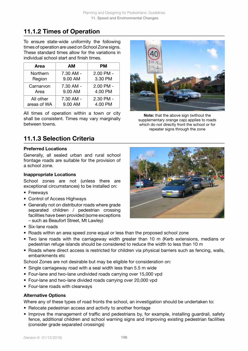
Planning and Designing for Pedestrians: Guidelines
196(Version 6- 01/12/2016)
11. Speed and Environmental Changes
11.1.2 Times of Operation
To ensure state-wide uniformity the following times of operation are used on School Zone signs. These standard times allow for the variations in individual school start and finish times.
Area AM PM
Northern Region
7.30 AM - 9.00 AM
2.00 PM - 3.30 PM
Carnarvon Area
7.30 AM - 9.00 AM
2.00 PM - 4.00 PM
All other areas of WA
7.30 AM - 9.00 AM
2.30 PM - 4.00 PM
All times of operation within a town or city shall be consistent. Times may vary marginally between towns.
Note: that the above sign (without the supplementary orange cap) applies to roads which do not directly front the school or for
repeater signs through the zone
11.1.3 Selection Criteria
Preferred LocationsGenerally, all sealed urban and rural school frontage roads are suitable for the provision of a school zone.
Inappropriate LocationsSchool zones are not (unless there are exceptional circumstances) to be installed on:• Freeways• ControlofAccessHighways• Generallynotondistributorroadswheregrade
separated children / pedestrian crossingfacilities have been provided (some exceptions– suchasBeaufortStreet,MtLawley)
• Six-laneroads• Roadswithinanareaspeedzoneequalorlessthantheproposedschoolzone• Two lane roadswith the carriagewaywidth greater than 10m (Kerb extensions,medians or
pedestrian refuge islands should be considered to reduce the width to less than 10 m• Roadswheredirectaccessisrestrictedforchildrenviaphysicalbarrierssuchasfencing,walls,
embankments etcSchool Zones are not desirable but may be eligible for consideration on:• Singlecarriagewayroadwithasealwidthlessthan5.5mwide• Four-laneandtwo-laneundividedroadscarryingover15,000vpd• Four-laneandtwo-lanedividedroadscarryingover20,000vpd• Four-laneroadswithclearways
Alternative OptionsWhere any of these types of road fronts the school, an investigation should be undertaken to:• Relocatepedestrianaccessandactivitytoanotherfrontage• Improvethemanagementoftrafficandpedestriansby,forexample,installingguardrail,safety
fence, additional children and school warning signs and improving existing pedestrian facilities(consider grade separated crossings)
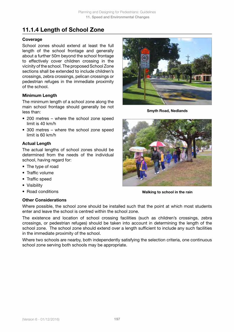
(Version 6 - 01/12/2016)
Planning and Designing for Pedestrians: Guidelines
197
11. Speed and Environmental Changes
11.1.4 Length of School Zone
CoverageSchool zones should extend at least the full length of the school frontage and generally about a further 50m beyond the school frontage to effectively cover children crossing in the vicinity of the school. The proposed School Zone sections shall be extended to include children’s crossings, zebra crossings, pelican crossings or pedestrian refuges in the immediate proximity of the school.
Minimum LengthThe minimum length of a school zone along the main school frontage should generally be not less than:
• 200metres –where the school zonespeedlimit is 40 km/h
• 300metres –where the school zonespeedlimit is 60 km/h
Actual LengthThe actual lengths of school zones should be determined from the needs of the individual school, having regard for:
• Thetypeofroad• Trafficvolume• Trafficspeed• Visibility• Roadconditions
Smyth Road, Nedlands
Walking to school in the rain
Other ConsiderationsWhere possible, the school zone should be installed such that the point at which most students enter and leave the school is centred within the school zone.
The existence and location of school crossing facilities (such as children’s crossings, zebra crossings, or pedestrian refuges) should be taken into account in determining the length of the school zone. The school zone should extend over a length sufficient to include any such facilities in the immediate proximity of the school.
Where two schools are nearby, both independently satisfying the selection criteria, one continuous school zone serving both schools may be appropriate.
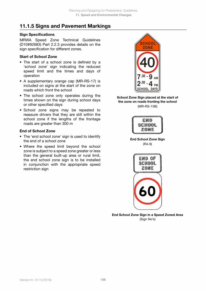
Planning and Designing for Pedestrians: Guidelines
198(Version 6- 01/12/2016)
11. Speed and Environmental Changes
11.1.5 Signs and Pavement Markings
Sign SpecificationsMRWA Speed Zone Technical Guidelines (D10#92683) Part 2.2.3 provides details on the sign specification for different zones.
Start of School Zone• The start of a school zone is defined by a
‘school zone’ sign indicating the reducedspeed limit and the times and days ofoperation
• A supplementaryorangecap (MR-RS-17) isincluded on signs at the start of the zone onroads which front the school
• The school zone only operates during thetimes shown on the sign during school daysor other specified days
• School zone signs may be repeated toreassure drivers that they are still within theschool zone if the lengths of the frontageroads are greater than 300 m
End of School Zone• The‘endschoolzone’signisusedtoidentify
the end of a school zone• Where the speed limit beyond the school
zone is subject to a speed zone greater or lessthan the general built-up area or rural limit,the end school zone sign is to be installedin conjunction with the appropriate speedrestriction sign
School Zone Sign placed at the start of the zone on roads fronting the school
(MR-RS-15B)
End School Zone Sign (R4-9)
End School Zone Sign in a Speed Zoned Area(Sign No’s)
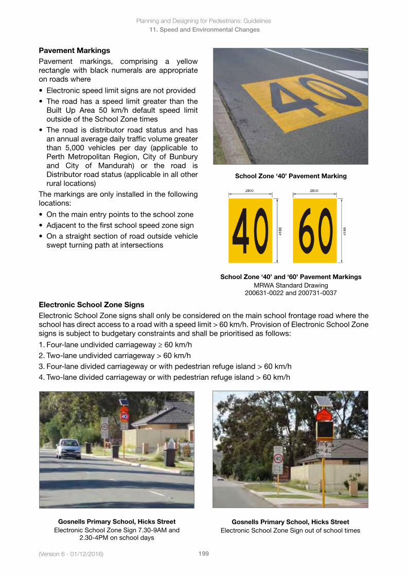
(Version 6 - 01/12/2016)
Planning and Designing for Pedestrians: Guidelines
199
11. Speed and Environmental Changes
Pavement MarkingsPavement markings, comprising a yellow rectangle with black numerals are appropriate on roads where
• Electronicspeedlimitsignsarenotprovided• The roadhasaspeed limitgreater than the
Built Up Area 50 km/h default speed limitoutside of the School Zone times
• The road is distributor road status and hasan annual average daily traffic volume greaterthan 5,000 vehicles per day (applicable toPerth Metropolitan Region, City of Bunburyand City of Mandurah) or the road isDistributor road status (applicable in all otherrural locations)
The markings are only installed in the following locations:
• Onthemainentrypointstotheschoolzone• Adjacenttothefirstschoolspeedzonesign• Onastraightsectionofroadoutsidevehicle
swept turning path at intersections
School Zone ‘40’ Pavement Marking
School Zone ‘40’ and ‘60’ Pavement MarkingsMRWA Standard Drawing
200631-0022 and 200731-0037
Electronic School Zone SignsElectronic School Zone signs shall only be considered on the main school frontage road where the schoolhasdirectaccesstoaroadwithaspeedlimit>60km/h.ProvisionofElectronicSchoolZonesigns is subject to budgetary constraints and shall be prioritised as follows:
1. Four-lane undivided carriageway ≥ 60 km/h2. Two-laneundividedcarriageway>60km/h3. Four-lanedividedcarriagewayorwithpedestrianrefugeisland>60km/h4. Two-lanedividedcarriagewayorwithpedestrianrefugeisland>60km/h
Gosnells Primary School, Hicks Street Electronic School Zone Sign 7.30-9AM and
2.30-4PM on school days
Gosnells Primary School, Hicks Street Electronic School Zone Sign out of school times
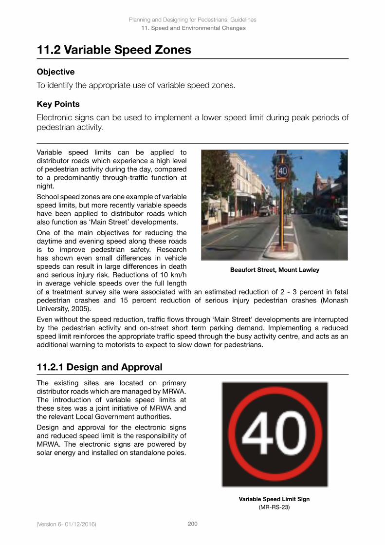
Planning and Designing for Pedestrians: Guidelines
200(Version 6- 01/12/2016)
11. Speed and Environmental Changes
11.2 Variable Speed Zones
Objective
To identify the appropriate use of variable speed zones.
Key Points
Electronic signs can be used to implement a lower speed limit during peak periods of pedestrian activity.
Variable speed limits can be applied to distributor roads which experience a high level of pedestrian activity during the day, compared to a predominantly through-traffic function at night.
School speed zones are one example of variable speed limits, but more recently variable speeds have been applied to distributor roads which also function as ‘Main Street’ developments.
One of the main objectives for reducing the daytime and evening speed along these roads is to improve pedestrian safety. Research has shown even small differences in vehicle speeds can result in large differences in death and serious injury risk. Reductions of 10 km/h in average vehicle speeds over the full length
Beaufort Street, Mount Lawley
of a treatment survey site were associated with an estimated reduction of 2 - 3 percent in fatal pedestrian crashes and 15 percent reduction of serious injury pedestrian crashes (Monash University, 2005).
Even without the speed reduction, traffic flows through ‘Main Street’ developments are interrupted by the pedestrian activity and on-street short term parking demand. Implementing a reduced speed limit reinforces the appropriate traffic speed through the busy activity centre, and acts as an additional warning to motorists to expect to slow down for pedestrians.
11.2.1 Design and Approval
The existing sites are located on primary distributor roads which are managed by MRWA. The introduction of variable speed limits at these sites was a joint initiative of MRWA and the relevant Local Government authorities.
Design and approval for the electronic signs and reduced speed limit is the responsibility of MRWA. The electronic signs are powered by solar energy and installed on standalone poles.
Variable Speed Limit Sign (MR-RS-23)
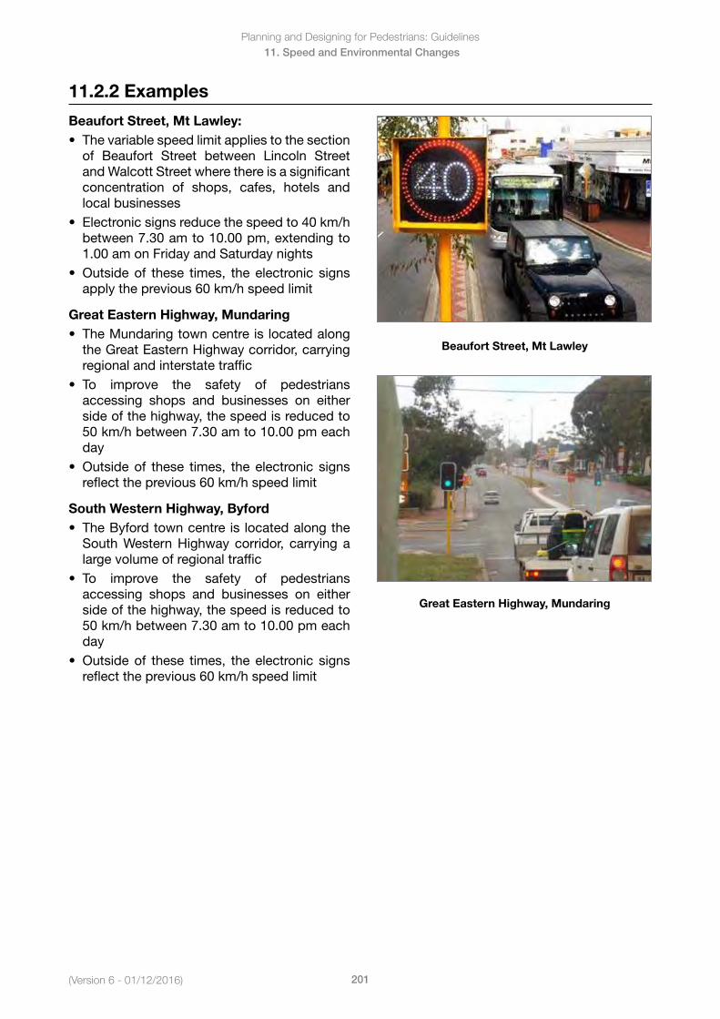
(Version 6 - 01/12/2016)
Planning and Designing for Pedestrians: Guidelines
201
11. Speed and Environmental Changes
11.2.2 Examples
Beaufort Street, Mt Lawley:• Thevariablespeedlimitappliestothesection
of Beaufort Street between Lincoln Streetand Walcott Street where there is a significantconcentration of shops, cafes, hotels andlocal businesses
• Electronicsignsreducethespeedto40km/hbetween 7.30 am to 10.00 pm, extending to1.00 am on Friday and Saturday nights
• Outsideof these times, theelectronic signsapply the previous 60 km/h speed limit
Great Eastern Highway, Mundaring• TheMundaringtowncentreislocatedalong
theGreatEasternHighwaycorridor,carryingregional and interstate traffic
• To improve the safety of pedestriansaccessing shops and businesses on eitherside of the highway, the speed is reduced to50 km/h between 7.30 am to 10.00 pm eachday
• Outsideof these times, theelectronic signsreflect the previous 60 km/h speed limit
South Western Highway, Byford• TheByfordtowncentreis locatedalongthe
SouthWesternHighway corridor, carrying alarge volume of regional traffic
• To improve the safety of pedestriansaccessing shops and businesses on eitherside of the highway, the speed is reduced to50 km/h between 7.30 am to 10.00 pm eachday
• Outsideof these times, theelectronic signsreflect the previous 60 km/h speed limit
Beaufort Street, Mt Lawley
Great Eastern Highway, Mundaring
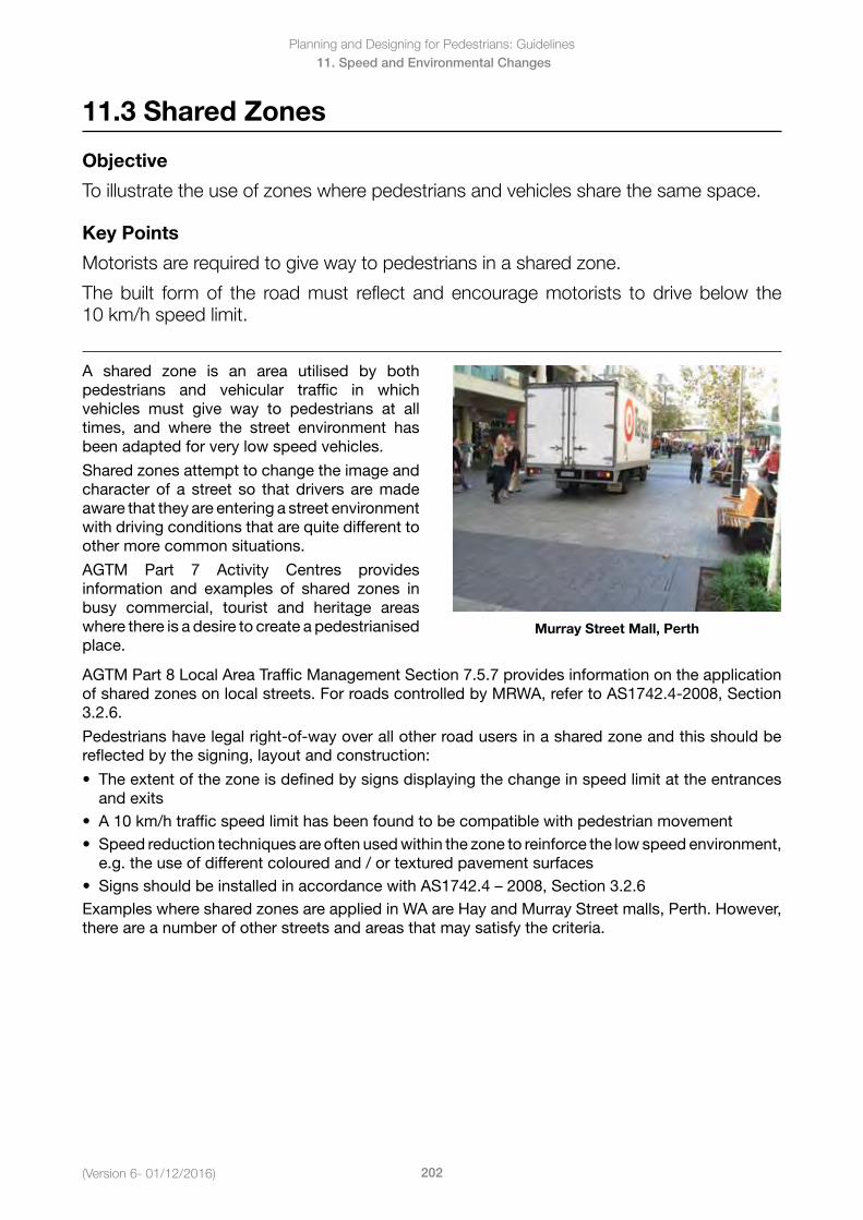
Planning and Designing for Pedestrians: Guidelines
202(Version 6- 01/12/2016)
11. Speed and Environmental Changes
11.3 Shared Zones
Objective
To illustrate the use of zones where pedestrians and vehicles share the same space.
Key Points
Motorists are required to give way to pedestrians in a shared zone.
The built form of the road must reflect and encourage motorists to drive below the 10 km/h speed limit.
A shared zone is an area utilised by both pedestrians and vehicular traffic in which vehicles must give way to pedestrians at all times, and where the street environment has been adapted for very low speed vehicles.
Shared zones attempt to change the image and character of a street so that drivers are made aware that they are entering a street environment with driving conditions that are quite different to other more common situations.
AGTM Part 7 Activity Centres provides information and examples of shared zones in busy commercial, tourist and heritage areas where there is a desire to create a pedestrianised place.
Murray Street Mall, Perth
AGTM Part 8 Local Area Traffic Management Section 7.5.7 provides information on the application of shared zones on local streets. For roads controlled by MRWA, refer to AS1742.4-2008, Section 3.2.6.
Pedestrians have legal right-of-way over all other road users in a shared zone and this should be reflected by the signing, layout and construction:
• Theextentofthezoneisdefinedbysignsdisplayingthechangeinspeedlimitattheentrancesand exits
• A10km/htrafficspeedlimithasbeenfoundtobecompatiblewithpedestrianmovement• Speedreductiontechniquesareoftenusedwithinthezonetoreinforcethelowspeedenvironment,
e.g. the use of different coloured and / or textured pavement surfaces• SignsshouldbeinstalledinaccordancewithAS1742.4–2008,Section3.2.6ExampleswheresharedzonesareappliedinWAareHayandMurrayStreetmalls,Perth.However,there are a number of other streets and areas that may satisfy the criteria.
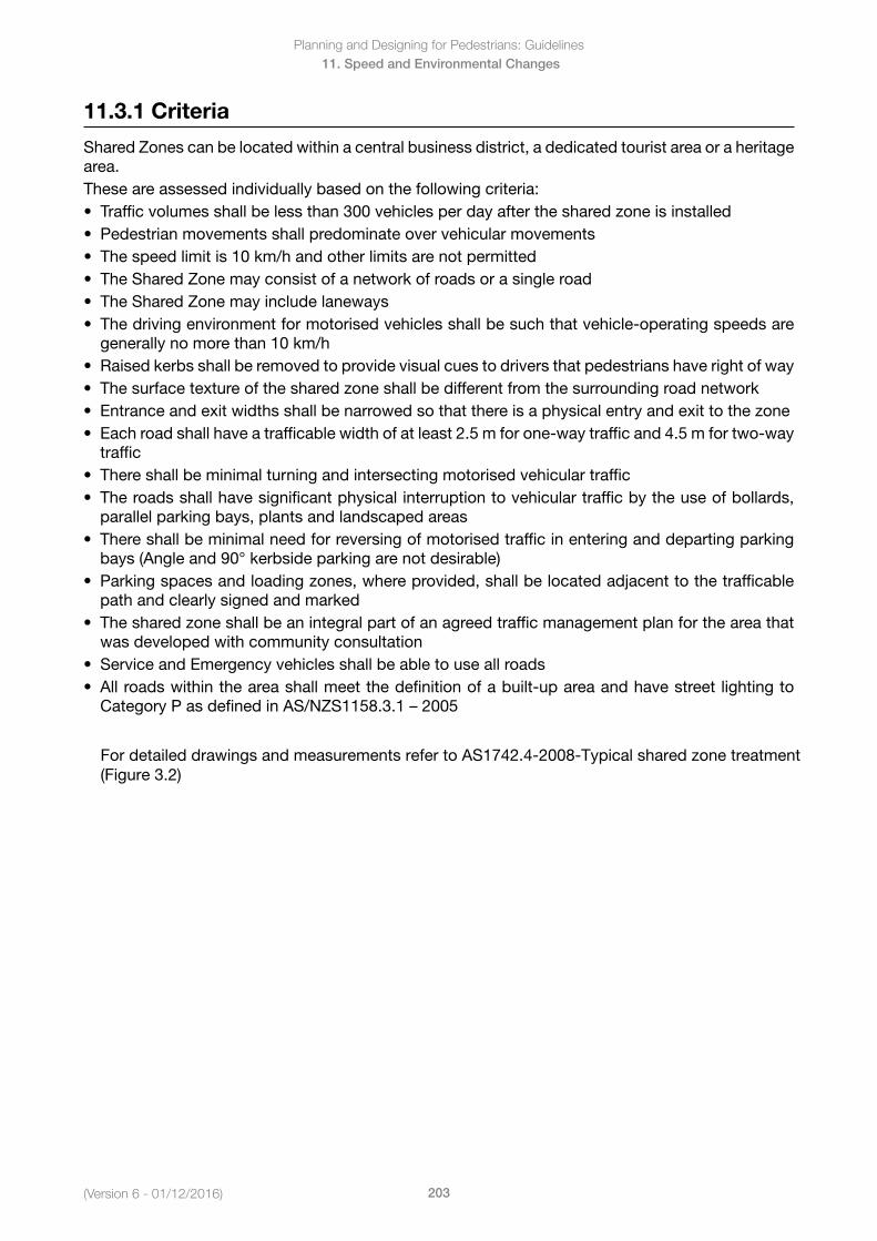
(Version 6 - 01/12/2016)
Planning and Designing for Pedestrians: Guidelines
203
11. Speed and Environmental Changes
11.3.1 Criteria
Shared Zones can be located within a central business district, a dedicated tourist area or a heritage area. These are assessed individually based on the following criteria:• Trafficvolumesshallbelessthan300vehiclesperdayafterthesharedzoneisinstalled• Pedestrianmovementsshallpredominateovervehicularmovements• Thespeedlimitis10km/handotherlimitsarenotpermitted• TheSharedZonemayconsistofanetworkofroadsorasingleroad• TheSharedZonemayincludelaneways• Thedrivingenvironmentformotorisedvehiclesshallbesuchthatvehicle-operatingspeedsare
generally no more than 10 km/h• Raisedkerbsshallberemovedtoprovidevisualcuestodriversthatpedestrianshaverightofway• Thesurfacetextureofthesharedzoneshallbedifferentfromthesurroundingroadnetwork• Entranceandexitwidthsshallbenarrowedsothatthereisaphysicalentryandexittothezone• Eachroadshallhaveatrafficablewidthofatleast2.5mforone-waytrafficand4.5mfortwo-way
traffic• Thereshallbeminimalturningandintersectingmotorisedvehiculartraffic• Theroadsshallhavesignificantphysicalinterruptiontovehiculartrafficbytheuseofbollards,
parallel parking bays, plants and landscaped areas• Thereshallbeminimalneedforreversingofmotorisedtrafficinenteringanddepartingparking
bays (Angle and 90° kerbside parking are not desirable)• Parkingspacesandloadingzones,whereprovided,shallbelocatedadjacenttothetrafficable
path and clearly signed and marked• Thesharedzoneshallbeanintegralpartofanagreedtrafficmanagementplanfortheareathat
was developed with community consultation• ServiceandEmergencyvehiclesshallbeabletouseallroads• Allroadswithintheareashallmeetthedefinitionofabuilt-upareaandhavestreet lightingto
CategoryPasdefinedinAS/NZS1158.3.1–2005
For detailed drawings and measurements refer to AS1742.4-2008-Typical shared zone treatment (Figure 3.2)
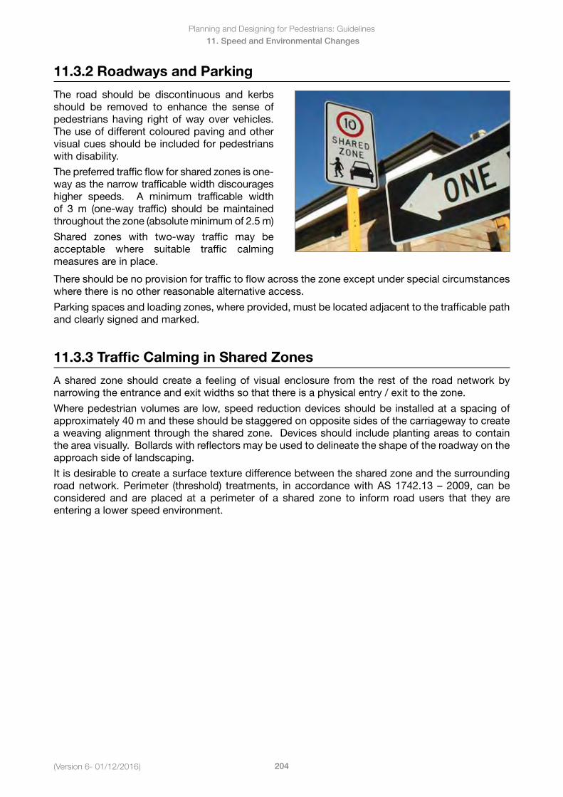
Planning and Designing for Pedestrians: Guidelines
204(Version 6- 01/12/2016)
11. Speed and Environmental Changes
11.3.2 Roadways and Parking
The road should be discontinuous and kerbs should be removed to enhance the sense of pedestrians having right of way over vehicles. The use of different coloured paving and other visual cues should be included for pedestrians with disability.
The preferred traffic flow for shared zones is one-way as the narrow trafficable width discourages higher speeds. A minimum trafficable width of 3 m (one-way traffic) should be maintained throughout the zone (absolute minimum of 2.5 m)
Shared zones with two-way traffic may be acceptable where suitable traffic calming measures are in place.
There should be no provision for traffic to flow across the zone except under special circumstances where there is no other reasonable alternative access.
Parking spaces and loading zones, where provided, must be located adjacent to the trafficable path and clearly signed and marked.
11.3.3 Traffic Calming in Shared Zones
A shared zone should create a feeling of visual enclosure from the rest of the road network by narrowing the entrance and exit widths so that there is a physical entry / exit to the zone.
Where pedestrian volumes are low, speed reduction devices should be installed at a spacing of approximately 40 m and these should be staggered on opposite sides of the carriageway to create a weaving alignment through the shared zone. Devices should include planting areas to contain the area visually. Bollards with reflectors may be used to delineate the shape of the roadway on the approach side of landscaping.
It is desirable to create a surface texture difference between the shared zone and the surrounding roadnetwork.Perimeter (threshold) treatments, inaccordancewithAS1742.13–2009,canbeconsidered and are placed at a perimeter of a shared zone to inform road users that they are entering a lower speed environment.
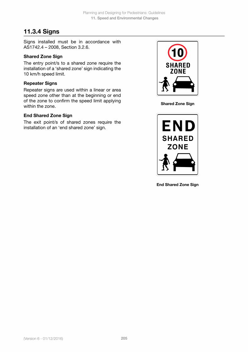
(Version 6 - 01/12/2016)
Planning and Designing for Pedestrians: Guidelines
205
11. Speed and Environmental Changes
11.3.4 Signs
Signs installed must be in accordance with AS1742.4–2008,Section3.2.6.
Shared Zone SignThe entry point/s to a shared zone require the installation of a ‘shared zone’ sign indicating the 10 km/h speed limit.
Repeater SignsRepeater signs are used within a linear or area speed zone other than at the beginning or end of the zone to confirm the speed limit applying within the zone.
End Shared Zone SignThe exit point/s of shared zones require the installation of an ‘end shared zone’ sign.
Shared Zone Sign
End Shared Zone Sign
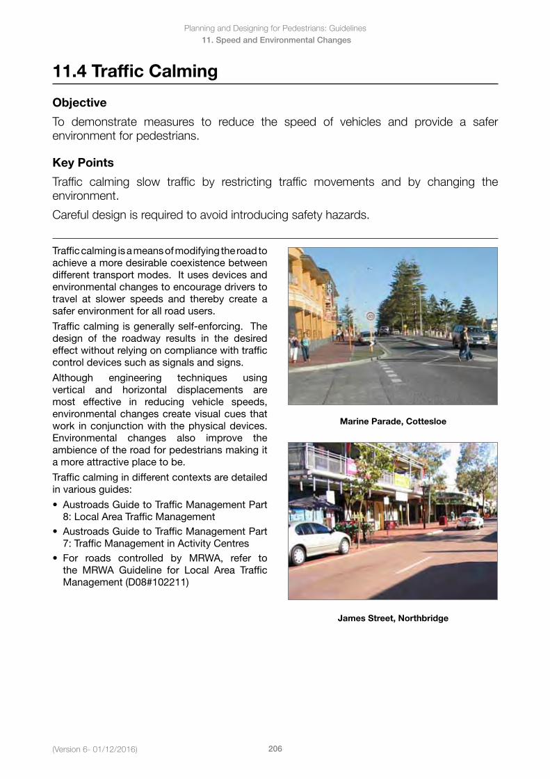
Planning and Designing for Pedestrians: Guidelines
206(Version 6- 01/12/2016)
11. Speed and Environmental Changes
11.4 Traffic Calming
Objective
To demonstrate measures to reduce the speed of vehicles and provide a safer environment for pedestrians.
Key Points
Traffic calming slow traffic by restricting traffic movements and by changing the environment.
Careful design is required to avoid introducing safety hazards.
Traffic calming is a means of modifying the road to achieve a more desirable coexistence between different transport modes. It uses devices and environmental changes to encourage drivers to travel at slower speeds and thereby create a safer environment for all road users.
Traffic calming is generally self-enforcing. The design of the roadway results in the desired effect without relying on compliance with traffic control devices such as signals and signs.
Although engineering techniques using vertical and horizontal displacements are most effective in reducing vehicle speeds, environmental changes create visual cues that work in conjunction with the physical devices. Environmental changes also improve the ambience of the road for pedestrians making it a more attractive place to be.
Traffic calming in different contexts are detailed in various guides:
• AustroadsGuidetoTrafficManagementPart8: Local Area Traffic Management
• AustroadsGuidetoTrafficManagementPart7: Traffic Management in Activity Centres
• For roads controlled by MRWA, refer tothe MRWA Guideline for Local Area TrafficManagement (D08#102211)
Marine Parade, Cottesloe
James Street, Northbridge
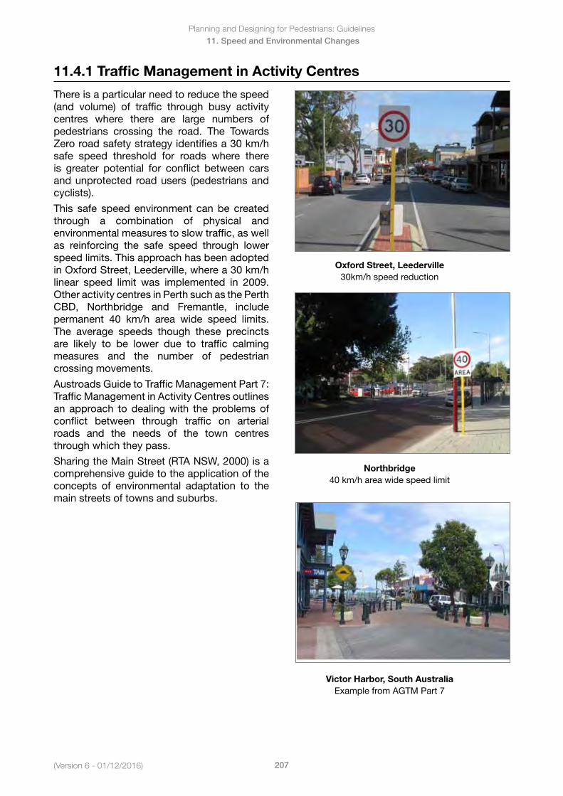
(Version 6 - 01/12/2016)
Planning and Designing for Pedestrians: Guidelines
207
11. Speed and Environmental Changes
11.4.1 Traffic Management in Activity Centres
There is a particular need to reduce the speed (and volume) of traffic through busy activity centres where there are large numbers of pedestrians crossing the road. The Towards Zero road safety strategy identifies a 30 km/h safe speed threshold for roads where there is greater potential for conflict between cars and unprotected road users (pedestrians and cyclists).
This safe speed environment can be created through a combination of physical and environmental measures to slow traffic, as well as reinforcing the safe speed through lower speed limits. This approach has been adopted in Oxford Street, Leederville, where a 30 km/h linear speed limit was implemented in 2009. Other activity centres in Perth such as the Perth CBD, Northbridge and Fremantle, include permanent 40 km/h area wide speed limits. The average speeds though these precincts are likely to be lower due to traffic calming measures and the number of pedestrian crossing movements.
Austroads Guide to Traffic Management Part 7: Traffic Management in Activity Centres outlines an approach to dealing with the problems of conflict between through traffic on arterial roads and the needs of the town centres through which they pass.
Sharing the Main Street (RTA NSW, 2000) is a comprehensive guide to the application of the concepts of environmental adaptation to the main streets of towns and suburbs.
Oxford Street, Leederville30km/h speed reduction
Northbridge 40 km/h area wide speed limit
Victor Harbor, South AustraliaExample from AGTM Part 7
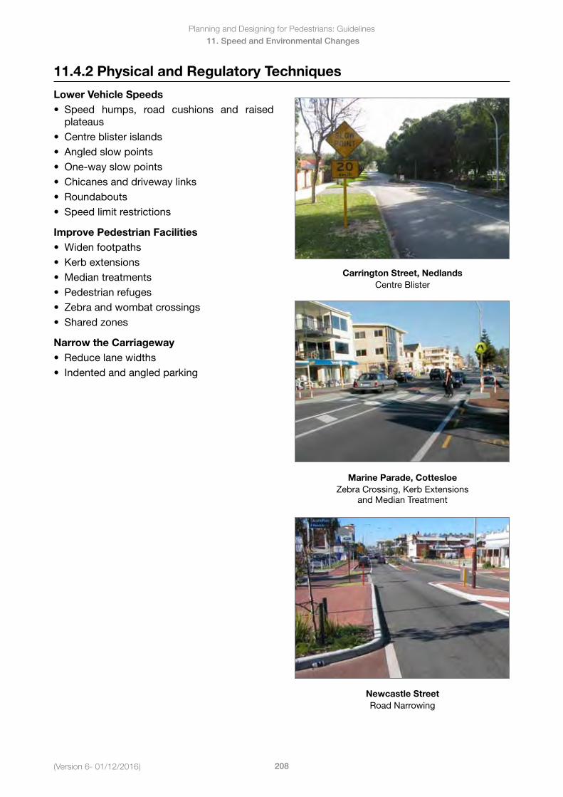
Planning and Designing for Pedestrians: Guidelines
208(Version 6- 01/12/2016)
11. Speed and Environmental Changes
11.4.2 Physical and Regulatory Techniques
Lower Vehicle Speeds• Speed humps, road cushions and raised
plateaus• Centreblisterislands• Angledslowpoints• One-wayslowpoints• Chicanesanddrivewaylinks• Roundabouts• Speedlimitrestrictions
Improve Pedestrian Facilities• Widenfootpaths• Kerbextensions• Mediantreatments• Pedestrianrefuges• Zebraandwombatcrossings• Sharedzones
Narrow the Carriageway• Reducelanewidths• Indentedandangledparking
Carrington Street, NedlandsCentre Blister
Marine Parade, CottesloeZebra Crossing, Kerb Extensions
and Median Treatment
Newcastle StreetRoad Narrowing
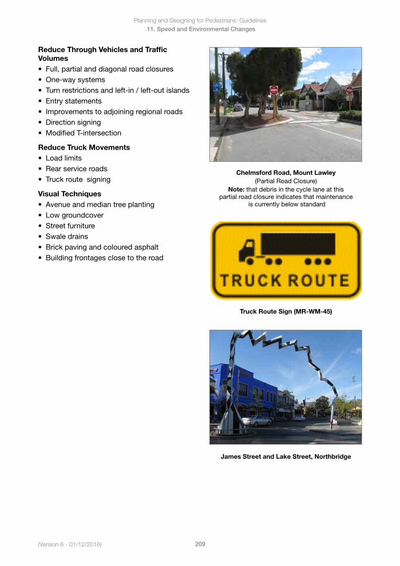
(Version 6 - 01/12/2016)
Planning and Designing for Pedestrians: Guidelines
209
11. Speed and Environmental Changes
Reduce Through Vehicles and Traffic Volumes• Full,partialanddiagonalroadclosures• One-waysystems• Turnrestrictionsandleft-in/left-outislands• Entrystatements• Improvementstoadjoiningregionalroads• Directionsigning• ModifiedT-intersection
Reduce Truck Movements• Loadlimits• Rearserviceroads• Truckroutesigning
Visual Techniques• Avenueandmediantreeplanting• Lowgroundcover• Streetfurniture• Swaledrains• Brickpavingandcolouredasphalt• Buildingfrontagesclosetotheroad
Chelmsford Road, Mount Lawley(Partial Road Closure)
Note: that debris in the cycle lane at this partial road closure indicates that maintenance
is currently below standard
Truck Route Sign (MR-WM-45)
James Street and Lake Street, Northbridge
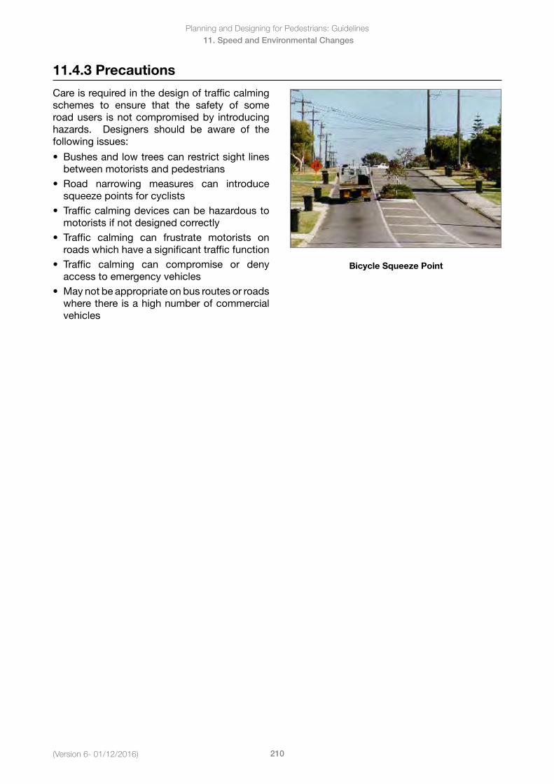
Planning and Designing for Pedestrians: Guidelines
210(Version 6- 01/12/2016)
11. Speed and Environmental Changes
11.4.3 Precautions
Care is required in the design of traffic calming schemes to ensure that the safety of some road users is not compromised by introducing hazards. Designers should be aware of the following issues:
• Bushesandlowtreescanrestrictsightlinesbetween motorists and pedestrians
• Road narrowing measures can introducesqueeze points for cyclists
• Trafficcalmingdevicescanbehazardoustomotorists if not designed correctly
• Traffic calming can frustrate motorists onroads which have a significant traffic function
• Traffic calming can compromise or denyaccess to emergency vehicles
• Maynotbeappropriateonbusroutesorroadswhere there is a high number of commercialvehicles
Bicycle Squeeze Point
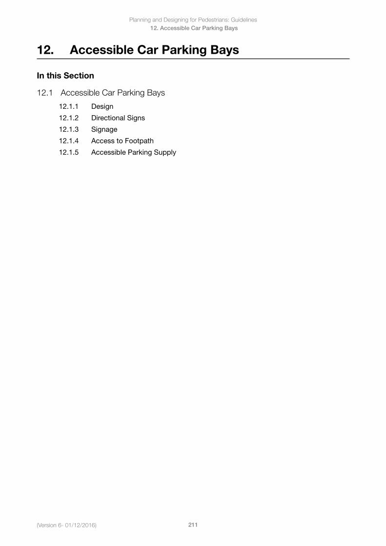
Planning and Designing for Pedestrians: Guidelines
211(Version 6- 01/12/2016)
12. Accessible Car Parking Bays
12. Accessible Car Parking Bays
In this Section
12.1 Accessible Car Parking Bays
12.1.1 Design
12.1.2 Directional Signs
12.1.3 Signage
12.1.4 Access to Footpath
12.1.5 Accessible Parking Supply
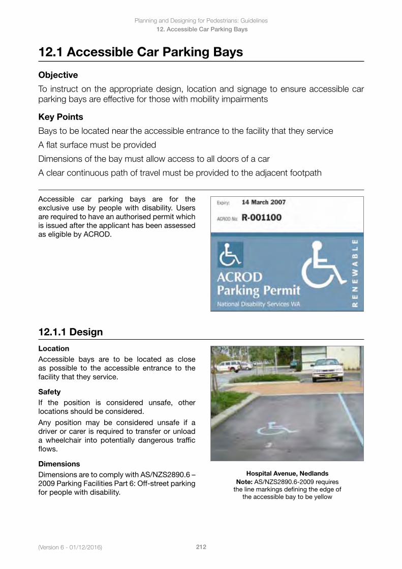
(Version 6 - 01/12/2016)
Planning and Designing for Pedestrians: Guidelines
212
12. Accessible Car Parking Bays
12.1 Accessible Car Parking Bays
Objective
To instruct on the appropriate design, location and signage to ensure accessible car parking bays are effective for those with mobility impairments
Key Points
Bays to be located near the accessible entrance to the facility that they service
A flat surface must be provided
Dimensions of the bay must allow access to all doors of a car
A clear continuous path of travel must be provided to the adjacent footpath
Accessible car parking bays are for the exclusive use by people with disability. Users are required to have an authorised permit which is issued after the applicant has been assessed as eligible by ACROD.
12.1.1 Design
LocationAccessible bays are to be located as close as possible to the accessible entrance to the facility that they service.
SafetyIf the position is considered unsafe, other locations should be considered.
Any position may be considered unsafe if a driver or carer is required to transfer or unload a wheelchair into potentially dangerous traffic flows.
DimensionsDimensionsaretocomplywithAS/NZS2890.6–2009 Parking Facilities Part 6: Off-street parking for people with disability.
Hospital Avenue, NedlandsNote: AS/NZS2890.6-2009 requires
the line markings defining the edge of the accessible bay to be yellow
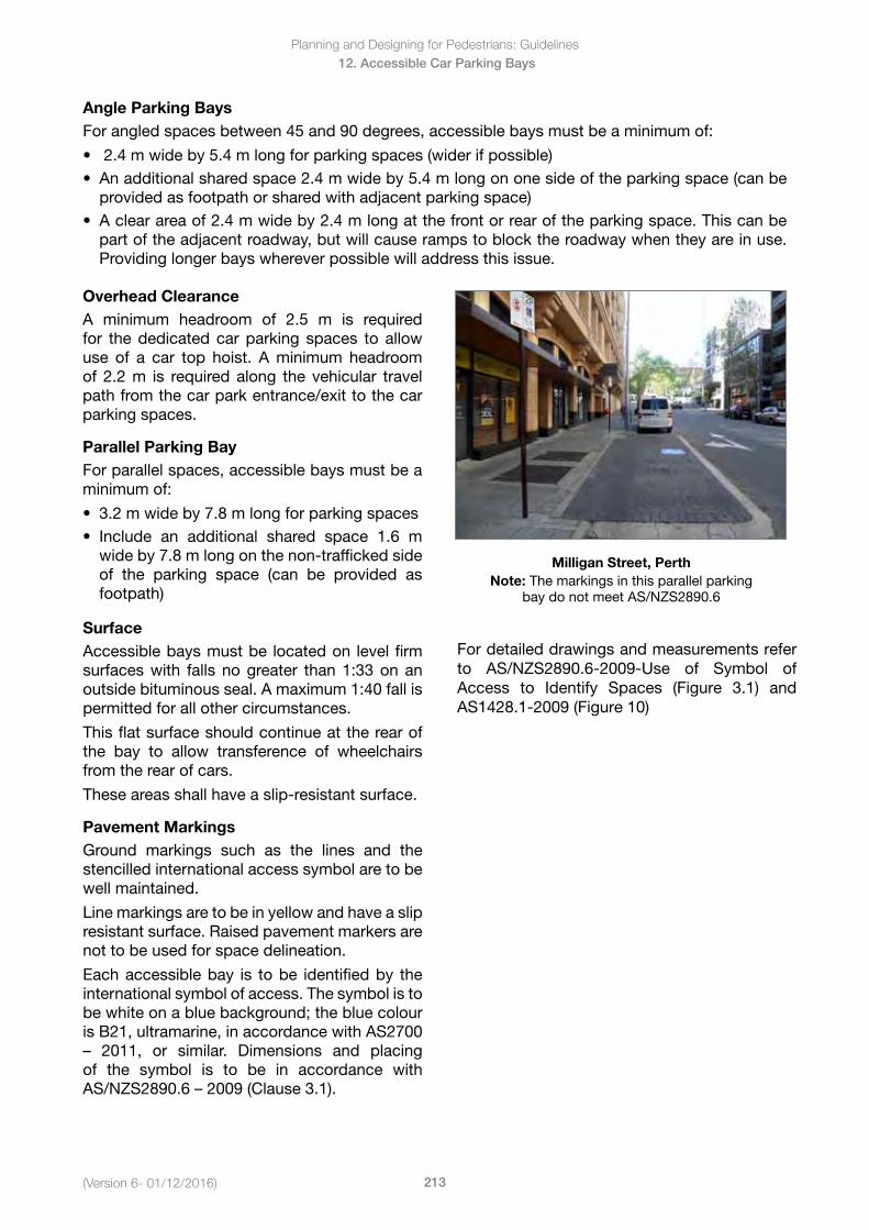
Planning and Designing for Pedestrians: Guidelines
213(Version 6- 01/12/2016)
12. Accessible Car Parking Bays
Angle Parking Bays For angled spaces between 45 and 90 degrees, accessible bays must be a minimum of:
• 2.4mwideby5.4mlongforparkingspaces(widerifpossible)• Anadditionalsharedspace2.4mwideby5.4mlongononesideoftheparkingspace(canbe
provided as footpath or shared with adjacent parking space)• Aclearareaof2.4mwideby2.4mlongatthefrontorrearoftheparkingspace.Thiscanbe
part of the adjacent roadway, but will cause ramps to block the roadway when they are in use.Providing longer bays wherever possible will address this issue.
Overhead ClearanceA minimum headroom of 2.5 m is required for the dedicated car parking spaces to allow use of a car top hoist. A minimum headroom of 2.2 m is required along the vehicular travel path from the car park entrance/exit to the car parking spaces.
Parallel Parking BayFor parallel spaces, accessible bays must be a minimum of:
• 3.2mwideby7.8mlongforparkingspaces• Include an additional shared space 1.6 m
wide by 7.8 m long on the non-trafficked sideof the parking space (can be provided asfootpath)
Milligan Street, PerthNote: The markings in this parallel parking
bay do not meet AS/NZS2890.6
SurfaceAccessible bays must be located on level firm surfaces with falls no greater than 1:33 on an outside bituminous seal. A maximum 1:40 fall is permitted for all other circumstances.
This flat surface should continue at the rear of the bay to allow transference of wheelchairs from the rear of cars.
These areas shall have a slip-resistant surface.
Pavement MarkingsGround markings such as the lines and the stencilled international access symbol are to be well maintained.
Line markings are to be in yellow and have a slip resistant surface. Raised pavement markers are not to be used for space delineation.
Each accessible bay is to be identified by the international symbol of access. The symbol is to be white on a blue background; the blue colour is B21, ultramarine, in accordance with AS2700 – 2011, or similar. Dimensions and placingof the symbol is to be in accordance with AS/NZS2890.6–2009(Clause3.1).
For detailed drawings and measurements refer to AS/NZS2890.6-2009-Use of Symbol of Access to Identify Spaces (Figure 3.1) and AS1428.1-2009 (Figure 10)
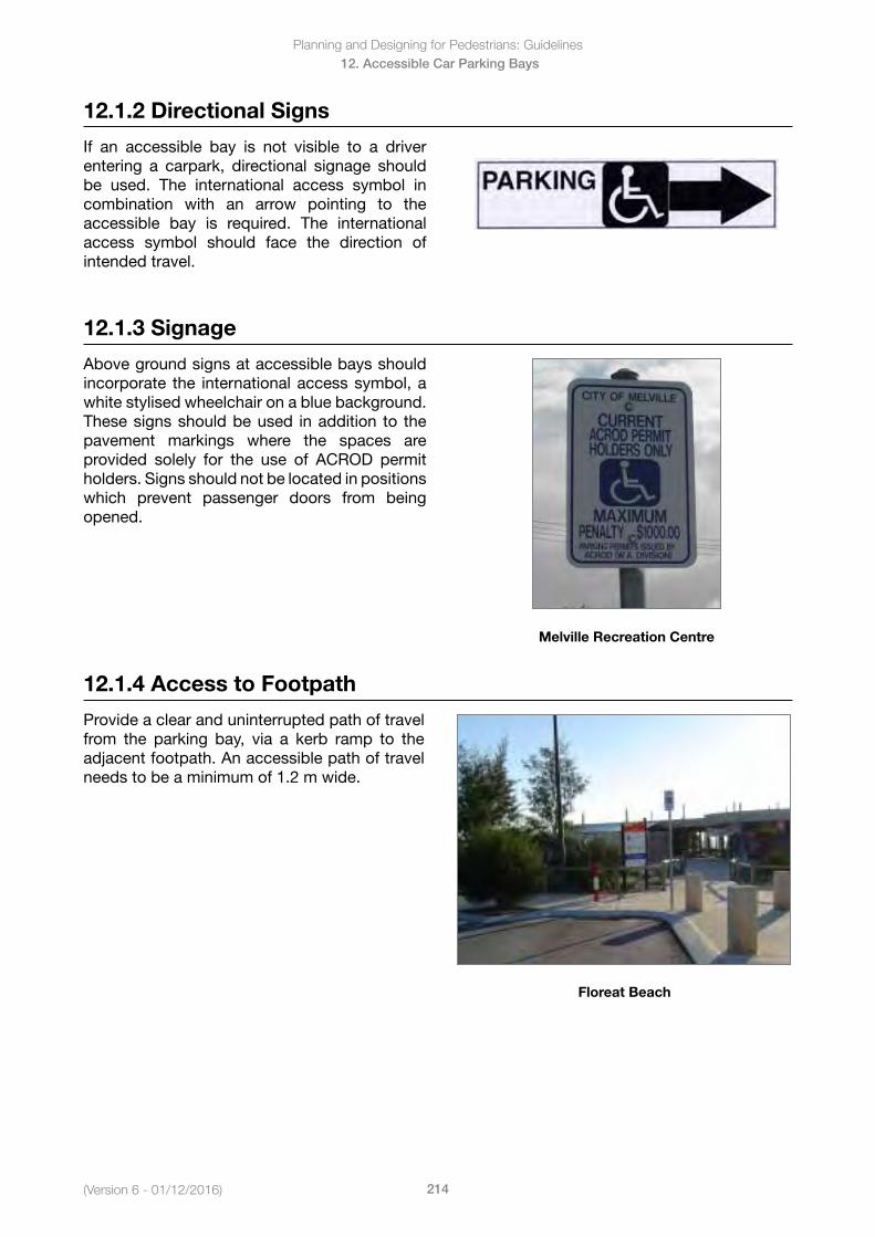
(Version 6 - 01/12/2016)
Planning and Designing for Pedestrians: Guidelines
214
12. Accessible Car Parking Bays
12.1.2 Directional Signs
If an accessible bay is not visible to a driver entering a carpark, directional signage should be used. The international access symbol in combination with an arrow pointing to the accessible bay is required. The international access symbol should face the direction of intended travel.
12.1.3 Signage
Above ground signs at accessible bays should incorporate the international access symbol, a white stylised wheelchair on a blue background. These signs should be used in addition to the pavement markings where the spaces are provided solely for the use of ACROD permit holders. Signs should not be located in positions which prevent passenger doors from being opened.
Melville Recreation Centre
12.1.4 Access to Footpath
Provide a clear and uninterrupted path of travel from the parking bay, via a kerb ramp to the adjacent footpath. An accessible path of travel needs to be a minimum of 1.2 m wide.
Floreat Beach
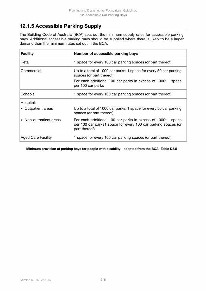
Planning and Designing for Pedestrians: Guidelines
215(Version 6- 01/12/2016)
12. Accessible Car Parking Bays
12.1.5 Accessible Parking Supply
The Building Code of Australia (BCA) sets out the minimum supply rates for accessible parking bays. Additional accessible parking bays should be supplied where there is likely to be a larger demand than the minimum rates set out in the BCA.
Facility Number of accessible parking bays
Retail 1 space for every 100 car parking spaces (or part thereof)
Commercial Up to a total of 1000 car parks: 1 space for every 50 car parking spaces (or part thereof)
For each additional 100 car parks in excess of 1000: 1 space per 100 car parks
Schools 1 space for every 100 car parking spaces (or part thereof)
Hospital:
• Outpatient areas
• Non-outpatient areas
Up to a total of 1000 car parks: 1 space for every 50 car parking spaces (or part thereof),
For each additional 100 car parks in excess of 1000: 1 space per 100 car parks1 space for every 100 car parking spaces (or part thereof)
Aged Care Facility 1 space for every 100 car parking spaces (or part thereof)
Minimum provision of parking bays for people with disability - adapted from the BCA- Table D3.5
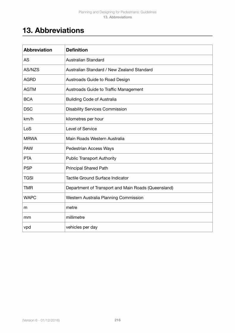
Planning and Designing for Pedestrians: Guidelines
216(Version 6 - 01/12/2016)
13. Abbreviations
13. Abbreviations
Abbreviation Definition
AS Australian Standard
AS/NZS Australian Standard / New Zealand Standard
AGRD Austroads Guide to Road Design
AGTM Austroads Guide to Traffic Management
BCA Building Code of Australia
DSC Disability Services Commission
km/h kilometres per hour
LoS Level of Service
MRWA Main Roads Western Australia
PAW Pedestrian Access Ways
PTA Public Transport Authority
PSP Principal Shared Path
TGSI Tactile Ground Surface Indicator
TMR Department of Transport and Main Roads (Queensland)
WAPC Western Australia Planning Commission
m metre
mm millimetre
vpd vehicles per day
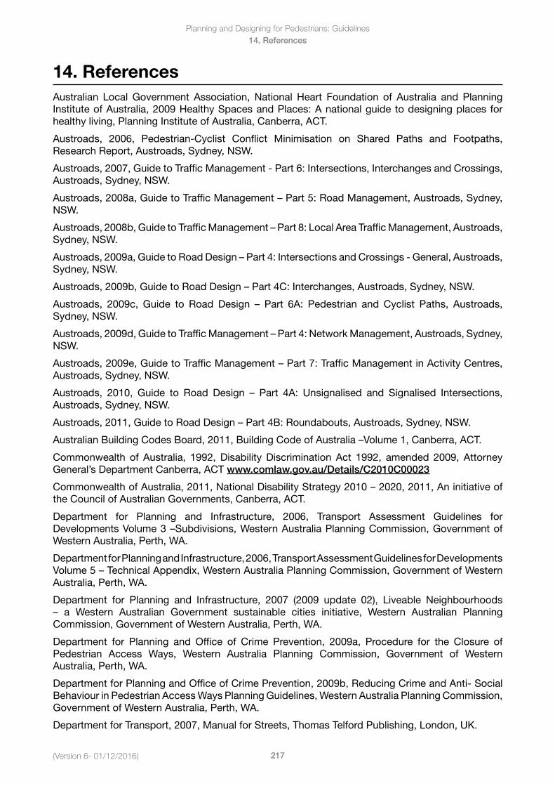
Planning and Designing for Pedestrians: Guidelines
217(Version 6- 01/12/2016)
14. References
14. ReferencesAustralian Local Government Association, National Heart Foundation of Australia and PlanningInstituteofAustralia,2009HealthySpacesandPlaces:Anationalguidetodesigningplacesforhealthy living, Planning Institute of Australia, Canberra, ACT.
Austroads, 2006, Pedestrian-Cyclist Conflict Minimisation on Shared Paths and Footpaths, Research Report, Austroads, Sydney, NSW.
Austroads, 2007, Guide to Traffic Management - Part 6: Intersections, Interchanges and Crossings, Austroads, Sydney, NSW.
Austroads,2008a,GuidetoTrafficManagement–Part5:RoadManagement,Austroads,Sydney,NSW.
Austroads,2008b,GuidetoTrafficManagement–Part8:LocalAreaTrafficManagement,Austroads,Sydney, NSW.
Austroads,2009a,GuidetoRoadDesign–Part4:IntersectionsandCrossings-General,Austroads,Sydney, NSW.
Austroads,2009b,GuidetoRoadDesign–Part4C:Interchanges,Austroads,Sydney,NSW.
Austroads, 2009c, Guide to Road Design – Part 6A: Pedestrian and Cyclist Paths, Austroads,Sydney, NSW.
Austroads,2009d,GuidetoTrafficManagement–Part4:NetworkManagement,Austroads,Sydney,NSW.
Austroads,2009e,GuidetoTrafficManagement–Part7:TrafficManagementinActivityCentres,Austroads, Sydney, NSW.
Austroads, 2010, Guide to Road Design – Part 4A: Unsignalised and Signalised Intersections,Austroads, Sydney, NSW.
Austroads,2011,GuidetoRoadDesign–Part4B:Roundabouts,Austroads,Sydney,NSW.
AustralianBuildingCodesBoard,2011,BuildingCodeofAustralia–Volume1,Canberra,ACT.
Commonwealth of Australia, 1992, Disability Discrimination Act 1992, amended 2009, Attorney General’s Department Canberra, ACT www.comlaw.gov.au/Details/C2010C00023
CommonwealthofAustralia,2011,NationalDisabilityStrategy2010–2020,2011,Aninitiativeofthe Council of Australian Governments, Canberra, ACT.
Department for Planning and Infrastructure, 2006, Transport Assessment Guidelines for DevelopmentsVolume3–Subdivisions,WesternAustraliaPlanningCommission,GovernmentofWestern Australia, Perth, WA.
Department for Planning and Infrastructure, 2006, Transport Assessment Guidelines for Developments Volume5– Technical Appendix, Western Australia Planning Commission, Government of Western Australia, Perth, WA.
Department for Planning and Infrastructure, 2007 (2009 update 02), Liveable Neighbourhoods – a Western Australian Government sustainable cities initiative, Western Australian PlanningCommission, Government of Western Australia, Perth, WA.
Department for Planning and Office of Crime Prevention, 2009a, Procedure for the Closure of Pedestrian Access Ways, Western Australia Planning Commission, Government of Western Australia, Perth, WA.
Department for Planning and Office of Crime Prevention, 2009b, Reducing Crime and Anti- Social Behaviour in Pedestrian Access Ways Planning Guidelines, Western Australia Planning Commission, Government of Western Australia, Perth, WA.
Department for Transport, 2007, Manual for Streets, Thomas Telford Publishing, London, UK.
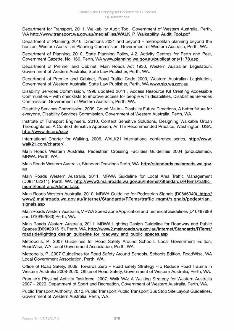
(Version 6 - 01/12/2016)
Planning and Designing for Pedestrians: Guidelines
218
14. References
Department for Transport, 2011, Walkability Audit Tool, Government of Western Australia, Perth, WA http://www.transport.wa.gov.au/mediaFiles/WALK_P_Walkability_Audit_Tool.pdf
DepartmentofPlanning,2010,Directions2031andbeyond–metropolitanplanningbeyondthehorizon, Western Australian Planning Commission, Government of Western Australia, Perth, WA.
Department of Planning, 2010, State Planning Policy, 4.2, Activity Centres for Perth and Peel, Government Gazette, No. 166, Perth, WA www.planning.wa.gov.au/publications/1178.asp
Department of Premier and Cabinet, Main Roads Act 1930, Western Australian Legislation, Government of Western Australia, State Law Publisher, Perth, WA.
Department of Premier and Cabinet, Road Traffic Code 2000, Western Australian Legislation, Government of Western Australia, State Law Publisher, Perth, WA www.slp.wa.gov.au
Disability Services Commission, 1996 updated 2011 , Access Resource Kit Creating Accessible Communities–withcheckliststoimproveaccessforpeoplewithdisabilities,DisabilitiesServicesCommission, Government of Western Australia, Perth, WA.
DisabilityServicesCommission,2009,CountMeIn–DisabilityFutureDirections,Abetterfutureforeveryone, Disability Services Commission, Government of Western Australia, Perth, WA.
Institute of Transport Engineers, 2010, Context Sensitive Solutions, Designing Walkable Urban Thoroughfares: A Context Sensitive Approach, An ITE Recommended Practice, Washington, USA, http://www.ite.org/css/
International Charter for Walking, 2006, WALK21 international conference series, http://www.walk21.com/charter/
Main Roads Western Australia, Pedestrian Crossing Facilities Guidelines 2004 (unpublished), MRWA, Perth, WA.
Main Roads Western Australia, Standard Drawings Perth, WA. http://standards.mainroads.wa.gov.au
Main Roads Western Australia, 2011, MRWA Guideline for Local Area Traffic Management (D08#102211), Perth, WA. http://www2.mainroads.wa.gov.au/Internet/Standards/RTems/traffic_mgmt/local_area/default.asp
Main Roads Western Australia, 2010, MRWA Guideline for Pedestrian Signals (D08#6040), http://www2.mainroads.wa.gov.au/Internet/Standards/RTems/traffic_mgmt/signals/pedestrian_signals.asp
Main Roads Western Australia, MRWA Speed Zone Application and Technical Guidelines (D10#87689 and D10#92683) Perth, WA.
Main Roads Western Australia, 2011, MRWA Lighting Design Guideline for Roadway and Public Spaces (D09#291515), Perth, WA. http://www2.mainroads.wa.gov.au/Internet/Standards/RTems/roadside/lighting_design_guideline_for_roadway_and_public_spaces.asp
Metropolis, P., 2007 Guidelines for Road Safety Around Schools, Local Government Edition, RoadWise, WA Local Government Association, Perth, WA.
Metropolis, P., 2007 Guidelines for Road Safety Around Schools, Schools Edition, RoadWise, WA Local Government Association, Perth, WA.
OfficeofRoadSafety,2009,TowardsZero–RoadsafetyStrategy -ToReduceRoadTrauma inWestern Australia 2008-2020, Office of Road Safety, Government of Western Australia, Perth, WA.
Premier’s Physical Activity Taskforce, 2007. Walk WA: A Walking Strategy for Western Australia 2007–2020.DepartmentofSportandRecreation,GovernmentofWesternAustralia,Perth,WA.
Public Transport Authority, 2010, Public Transport Public Transport Bus Stop Site Layout Guidelines. Government of Western Australia, Perth, WA.
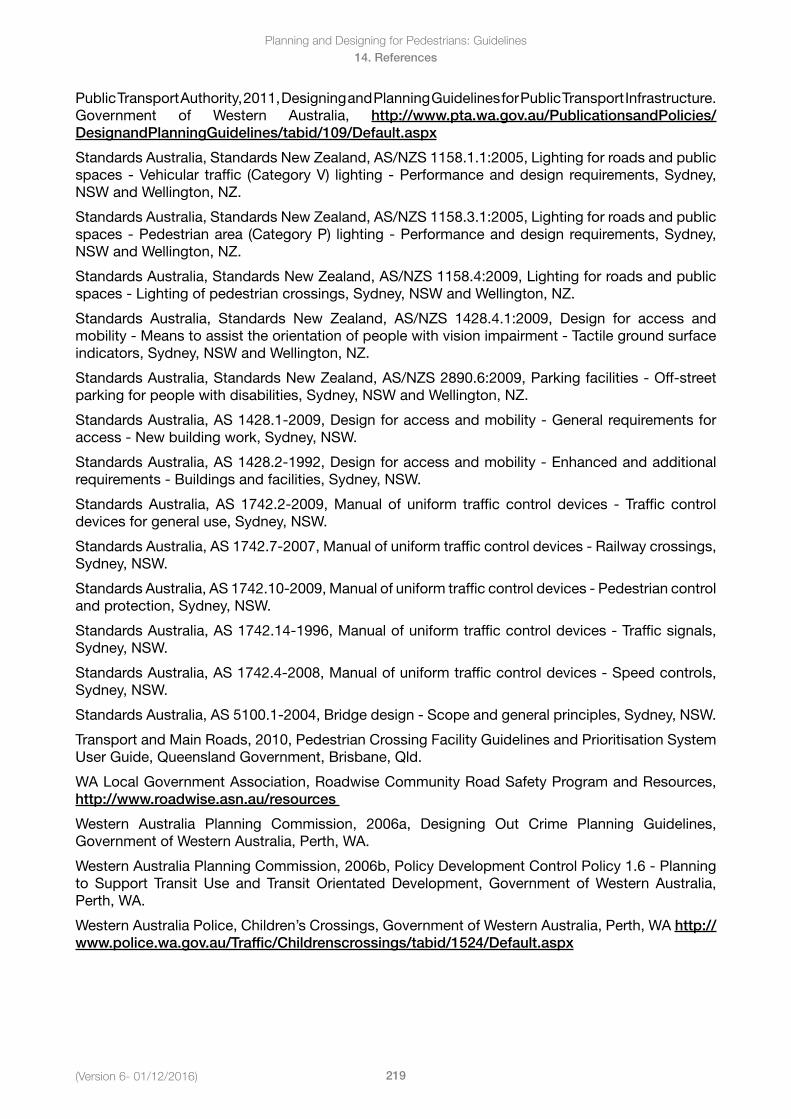
Planning and Designing for Pedestrians: Guidelines
219(Version 6- 01/12/2016)
14. References
Public Transport Authority, 2011, Designing and Planning Guidelines for Public Transport Infrastructure. Government of Western Australia, http://www.pta.wa.gov.au/PublicationsandPolicies/DesignandPlanningGuidelines/tabid/109/Default.aspx
Standards Australia, Standards New Zealand, AS/NZS 1158.1.1:2005, Lighting for roads and public spaces - Vehicular traffic (Category V) lighting - Performance and design requirements, Sydney, NSW and Wellington, NZ.
Standards Australia, Standards New Zealand, AS/NZS 1158.3.1:2005, Lighting for roads and public spaces - Pedestrian area (Category P) lighting - Performance and design requirements, Sydney, NSW and Wellington, NZ.
Standards Australia, Standards New Zealand, AS/NZS 1158.4:2009, Lighting for roads and public spaces - Lighting of pedestrian crossings, Sydney, NSW and Wellington, NZ.
Standards Australia, Standards New Zealand, AS/NZS 1428.4.1:2009, Design for access and mobility - Means to assist the orientation of people with vision impairment - Tactile ground surface indicators, Sydney, NSW and Wellington, NZ.
Standards Australia, Standards New Zealand, AS/NZS 2890.6:2009, Parking facilities - Off-street parking for people with disabilities, Sydney, NSW and Wellington, NZ.
Standards Australia, AS 1428.1-2009, Design for access and mobility - General requirements for access - New building work, Sydney, NSW.
Standards Australia, AS 1428.2-1992, Design for access and mobility - Enhanced and additional requirements - Buildings and facilities, Sydney, NSW.
Standards Australia, AS 1742.2-2009, Manual of uniform traffic control devices - Traffic control devices for general use, Sydney, NSW.
Standards Australia, AS 1742.7-2007, Manual of uniform traffic control devices - Railway crossings, Sydney, NSW.
Standards Australia, AS 1742.10-2009, Manual of uniform traffic control devices - Pedestrian control and protection, Sydney, NSW.
Standards Australia, AS 1742.14-1996, Manual of uniform traffic control devices - Traffic signals, Sydney, NSW.
Standards Australia, AS 1742.4-2008, Manual of uniform traffic control devices - Speed controls, Sydney, NSW.
Standards Australia, AS 5100.1-2004, Bridge design - Scope and general principles, Sydney, NSW.
Transport and Main Roads, 2010, Pedestrian Crossing Facility Guidelines and Prioritisation System User Guide, Queensland Government, Brisbane, Qld.
WA Local Government Association, Roadwise Community Road Safety Program and Resources, http://www.roadwise.asn.au/resources
Western Australia Planning Commission, 2006a, Designing Out Crime Planning Guidelines, Government of Western Australia, Perth, WA.
Western Australia Planning Commission, 2006b, Policy Development Control Policy 1.6 - Planning to Support Transit Use and Transit Orientated Development, Government of Western Australia, Perth, WA.
Western Australia Police, Children’s Crossings, Government of Western Australia, Perth, WA http://www.police.wa.gov.au/Traffic/Childrenscrossings/tabid/1524/Default.aspx