Embed Size (px)
Citation preview
Plans for FP7 at DESY, October 30th, 2006 CERN Jacek Sekutowicz
1/19
Proposed Joint Research Activity at DESY in Frame of FP7 Status October 2006.
General Remark
JRA at DESY has been meant as R&D program for the performance improvement of two existing facilities at DESY:
1. TTF-II / FLASH 2. Cryomodule Test Bed (CMTB).
All achievements can be later implemented in the European XFEL and other FEL facilities in Europe and World-wide

Plans for FP7 at DESY, October 30th, 2006 CERN Jacek Sekutowicz
2/19
Work package (WP) Responsible person at DESY
Implementation/ Future Implementation
1 Superconducting RF gun J. Sekutowicz FLASH/XFEL/FELs
2 CW operating transmitter J. Sekutowicz CMTB/XFEL/FELs
3 LLRF controls S. Simrock FLASH/XFEL/FELs
4 Timing & synchronization for SC FEL H. Schlarb FLASH/XFEL/FELs
5 Large grain / single crystal Nb resonators W. Singer CMTB/FLASH/XFEL/FELs
6 Improvement of the 3.9 GHz higher harmonic system
M. Huening FLASH/SC FEL
7 "LOLA" at 3 GHz-Longitudinal bunch phase-space measurements
M. Huening FLASH/XFEL/FELs
8 HOM beam monitors N. Baboi FLASH/XFEL/FELs
Summary of SRF WPs proposed at DESY
Topics and Implementations

Plans for FP7 at DESY, October 30th, 2006 CERN Jacek Sekutowicz
3/19
Work package (WP) Collaborating Countries
Collaborating Institutions
1 Superconducting RF gun Germany, Italy, Poland, USA
DESY, INFN, INS, JLab, BNL, SLAC
2 CW operating transmitter Germany, USA DESY, FuG, CPI
3 LLRF controls Germany, Poland, Italy, France; Switzerland
DESY, IPNO Orsay, INFN Padova, PSI, ISE, IN2P3, DMCS
4 Timing & synchronization for SC FEL Germany, UK, Turkey DESY, Daresbury, Bilkent
5 Large grain / single crystal Nb resonators Germany, USA DESY, JLab, OSU, CUT, IBF, Wuppertal Uni.
6 Improvement of the 3.9 GHz higher harmonic system
Germany, USA DESY, FNAL
7 "LOLA" at 3 GHz-Longitudinal bunch phase-space measurements
Germany, USA DESY, SLAC, Univ. Darmstadt
8 HOM beam monitors Germany, France, UK, USA, Japan
DESY, SLAC, FNAL, CEA, KEK…
Summary of SRF WPs proposed at DESY
Countries and Institutions

Plans for FP7 at DESY, October 30th, 2006 CERN Jacek Sekutowicz
4/19
Work package (WP) FTEs over whole FP7 period
Estimated Total Costs [k€]
(FTEs not included)
1 Superconducting RF gun 2 710
2 CW operating transmitter 2 350 (IOT) + 350 (Power supply) +100 (Preamp.)
3 LLRF controls 58 (4 years period) 2590
4 Timing & synchronization for SC FEL 20 2200
5 Large grain / single crystal Nb resonators Not defined yet 500
6 Improvement of the 3.9 GHz higher harmonic system
6 1360
7 "LOLA" at 3 GHz-Longitudinal bunch phase-space measurements
6 210
8 HOM beam monitors 6 (3 years) 1620
Total (Preliminary Status, October 2006) 100 x 70k€ 7000 k€ 9990
Summary of SRF WPs proposed at DESY, cont
Costs and FTEs

Plans for FP7 at DESY, October 30th, 2006 CERN Jacek Sekutowicz
5/19
1. Superconducting RF gun
MotivationSCR-gun operating in continuous wave (cw) or near-cw mode, which does not exist at present, will allow for much higher number of bunches generated per second and will increase average brilliance of many FEL facilities driven by the superconducting accelerators.
Technology differs from other approachesBulk niobium 1.5-cell cavity with arc deposited emitting spot of lead, which is very good superconductor. Use of superconducting photo-cathode simplifies construction of the cavity which operate with very long life time cathode.
Encouraging results of Quantum Efficiency tests and RF-tests of half cell with the lead spot have been published by the applying Collaboration.
1.E+08
1.E+09
1.E+10
0 10 20 30 40 50Epeak[MV/m]
Qo
"Nb Plug"Lead Plug #2
0.000
0.006
4.0 4.5 5.0 5.5 6.0 6.5 7.0
Pb: vacuum-depositedPb: bulkPb: electro-platedNb: bulkPb: arc-depositedPb: magnetron-deposited
190
nm
193
nm
200
nm
210
nm21
3 nm
220
nm
230
nm
240
nm
Ep [eV]
QE
248
nm

Plans for FP7 at DESY, October 30th, 2006 CERN Jacek Sekutowicz
6/19
1. Superconducting RF gun
What should be done in the frame of work package
Cavities, Auxiliaries and PreparationsFabrication of two Nb prototypes of the 1.5-cell RF-gun cavityPreparation and cryogenic testing of cavities Cavity transport costs (round trip INS-DESY)
RF- modeling cost (SLAC- sub partner)CryostatTuner Input Coupler
:Apparatus for coating which will be added to the existing setup
Ultra high vacuum Turbo pumpValve Leak detector Power supplier for arc discharging Laser initializing the arc Clean Room
Plans for FP7 at DESY, October 30th, 2006 CERN Jacek Sekutowicz
7/19
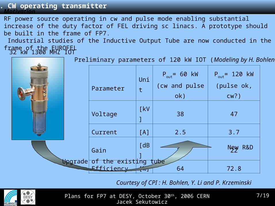
2. CW operating transmitter
MotivationRF power source operating in cw and pulse mode enabling substantial increase of the duty factor of FEL driving sc linacs. A prototype should be built in the frame of FP7. Industrial studies of the Inductive Output Tube are now conducted in the frame of the EUROFEL
Preliminary parameters of 120 kW IOT (Modeling by H. Bohlen)
ParameterUnit
Pout= 60 kW
(cw and pulse ok)
Pout= 120 kW
(pulse ok, cw?)
Voltage [kV] 38 47
Current [A] 2.5 3.7
Gain [dB] 22 22
Efficiency [%] 64 72.8
32 kW 1300 MHZ IOT
Upgrade of the existing tube
New R&D
Courtesy of CPI : H. Bohlen, Y. Li and P. Krzeminski
Plans for FP7 at DESY, October 30th, 2006 CERN Jacek Sekutowicz
8/19
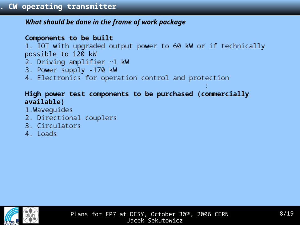
2. CW operating transmitter
What should be done in the frame of work package
Components to be built 1. IOT with upgraded output power to 60 kW or if technically possible to 120 kW2. Driving amplifier ~1 kW3. Power supply -170 kW4. Electronics for operation control and protection
:High power test components to be purchased (commercially available) 1.Waveguides2. Directional couplers3. Circulators4. Loads

Plans for FP7 at DESY, October 30th, 2006 CERN Jacek Sekutowicz
9/19
3. LLRF controls
MotivationAdvance RF Control Technology in the areas of hardware and software to meet the requirements for FLASH and European XFEL.
What should be done in the frame of work package1. Develop LLRF implementation as HA ATCA System 2. Develop concept for modular system 3. Develop multi-channel ASIC version of downconverter 4. Develop multi-channel downconverter board based on ASIC to standard component 5. High degree of automation for large scale system, operability 6. Reliability and availability optimization and cost reduction 7. Technical performance, pushing the envelope of performance
Sub-tasks
1. HA (High Availability) LLRF Implementation in ATCA
The demand for high availability, modularity, standardization and long time support favors the choice of the ATCA and TCA standard with carrier boards and AMC modules. This technology is basis for the ILC technical design. Presently none of the required AMC boards for ADCs, DACs, downconverters, clock synthesizers etc. are available. Therefore a development of these boards using state-of-the-art technology is necessary.
Plans for FP7 at DESY, October 30th, 2006 CERN Jacek Sekutowicz
10/19
Sub-tasks, cont.
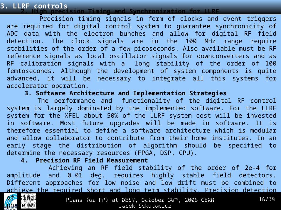
2. High precision Timing and Synchronization for LLRF Precision timing signals in form of clocks and event triggers are required for digital control
system to guarantee synchronicity of ADC data with the electron bunches and allow for digital RF field detection. The clock signals are in the 100 MHz range require stabilities of the order of a few picoseconds. Also available must be RF reference signals as local oscillator signals for downconverters and as RF calibration signals with a long stability of the order of 100 femtoseconds. Although the development of system components is quite advanced, it will be necessary to integrate all this systems for accelerator operation.
3. Software Architecture and Implementation Strategies The performance and functionality of the digital RF control system is largely dominated by
the implemented software. For the LLRF system for the XFEL about 50% of the LLRF system cost will be invested in software. Most future upgrades will be made in software. It is therefore essential to define a software architecture which is modular and allow collaborator to contribute from their home institutes. In an early stage the distribution of algorithm should be specified to determine the necessary resources (FPGA, DSP, CPU).
4. Precision RF Field Measurement Achieving an RF field stability of the order of 2e-4 for amplitude and 0.01 deg. requires
highly stable field detectors. Different approaches for low noise and low drift must be combined to achieve the required short and long term stability. Precision detection of single bunch induced transients is necessary to determine the beam phase without risk of vacuum loss and beamline activation.
3. LLRF controls
Plans for FP7 at DESY, October 30th, 2006 CERN Jacek Sekutowicz
11/19
Sub-tasks, cont..
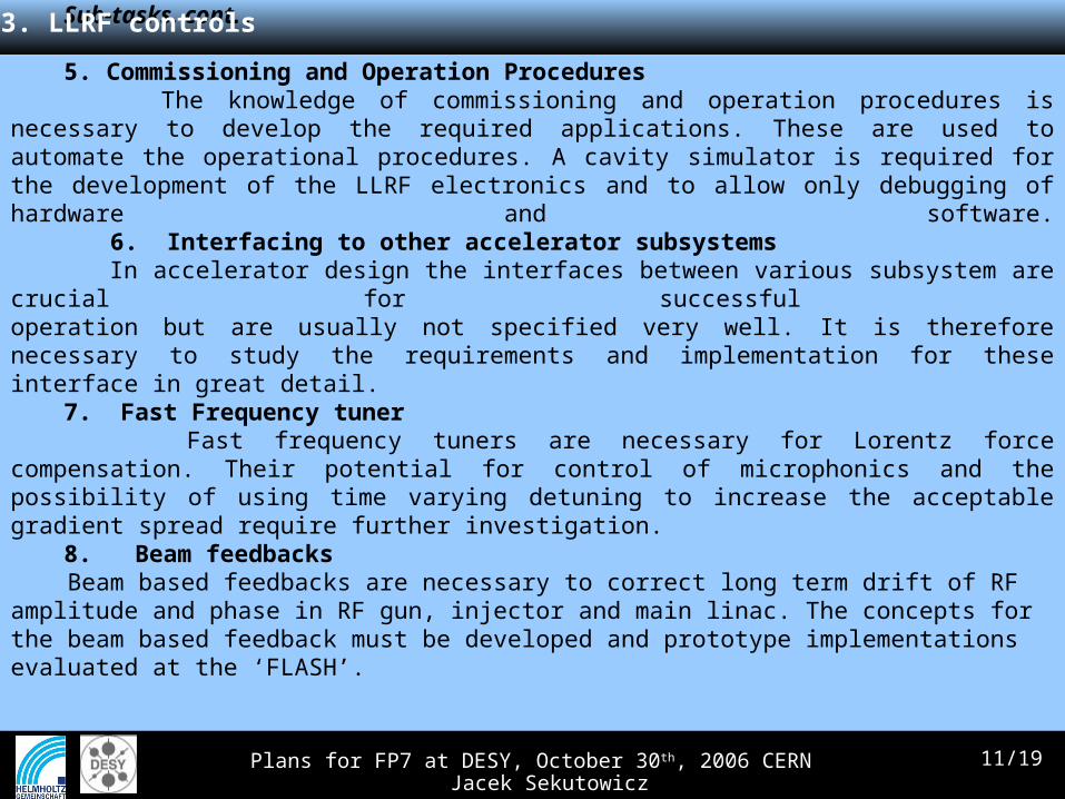
5. Commissioning and Operation Procedures The knowledge of commissioning and operation procedures is necessary to develop the
required applications. These are used to automate the operational procedures. A cavity simulator is required for the development of the LLRF electronics and to allow only debugging of hardware and software. 6. Interfacing to other accelerator subsystems
In accelerator design the interfaces between various subsystem are crucial for successful operation but are usually not specified very well. It is therefore necessary to study the requirements and implementation for these interface in great detail.
7. Fast Frequency tuner Fast frequency tuners are necessary for Lorentz force compensation. Their potential for
control of microphonics and the possibility of using time varying detuning to increase the acceptable gradient spread require further investigation.
8. Beam feedbacks Beam based feedbacks are necessary to correct long term drift of RF amplitude and phase in RF gun, injector and main linac. The concepts for the beam based feedback must be developed and prototype implementations evaluated at the ‘FLASH’.
3. LLRF controls

Plans for FP7 at DESY, October 30th, 2006 CERN Jacek Sekutowicz
12/19
4. Timing & synchronization for SC FEL
MotivationSynchronization on sub-femtosecond time scale especially for all kind of pump-probe experiments
For FELs:
Photo-cathode laser
RF gun
Booster
undulator
Pump-probe laser
Acc. module
compressor
Introduces unavoidable timing jitter ~ 30-60fs
Manipulation laser
Femtosecondoptical link
Only way towards fs with external seed laser!
Plans for FP7 at DESY, October 30th, 2006 CERN Jacek Sekutowicz
13/19
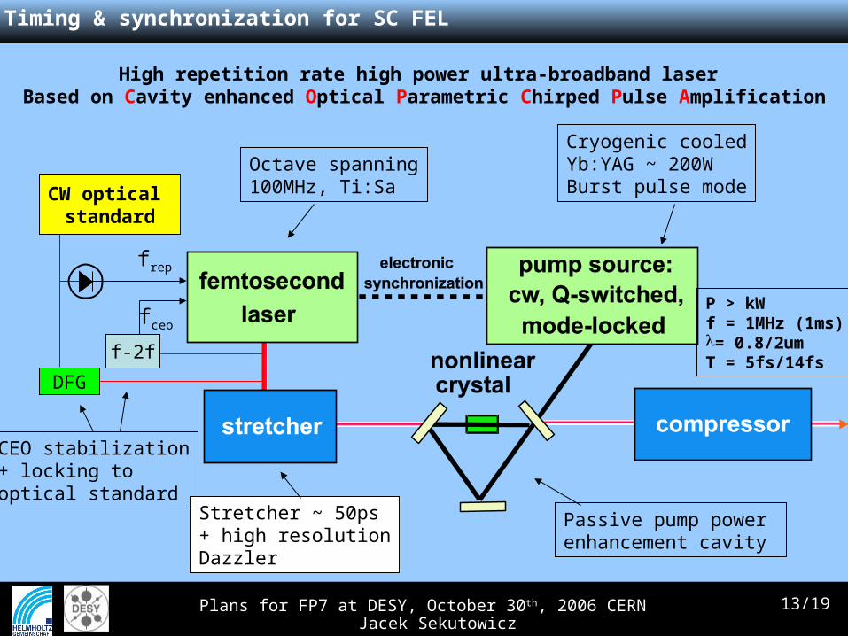
High repetition rate high power ultra-broadband laser Based on Cavity enhanced Optical Parametric Chirped Pulse Amplification
f-2f
fceo
DFG
frep
CW optical standard
Octave spanning100MHz, Ti:Sa
Stretcher ~ 50ps+ high resolutionDazzler
CEO stabilization+ locking to optical standard
Cryogenic cooledYb:YAG ~ 200WBurst pulse mode
Passive pump powerenhancement cavity
P > kWf = 1MHz (1ms)= 0.8/2umT = 5fs/14fs
4. Timing & synchronization for SC FEL
Plans for FP7 at DESY, October 30th, 2006 CERN Jacek Sekutowicz
14/19
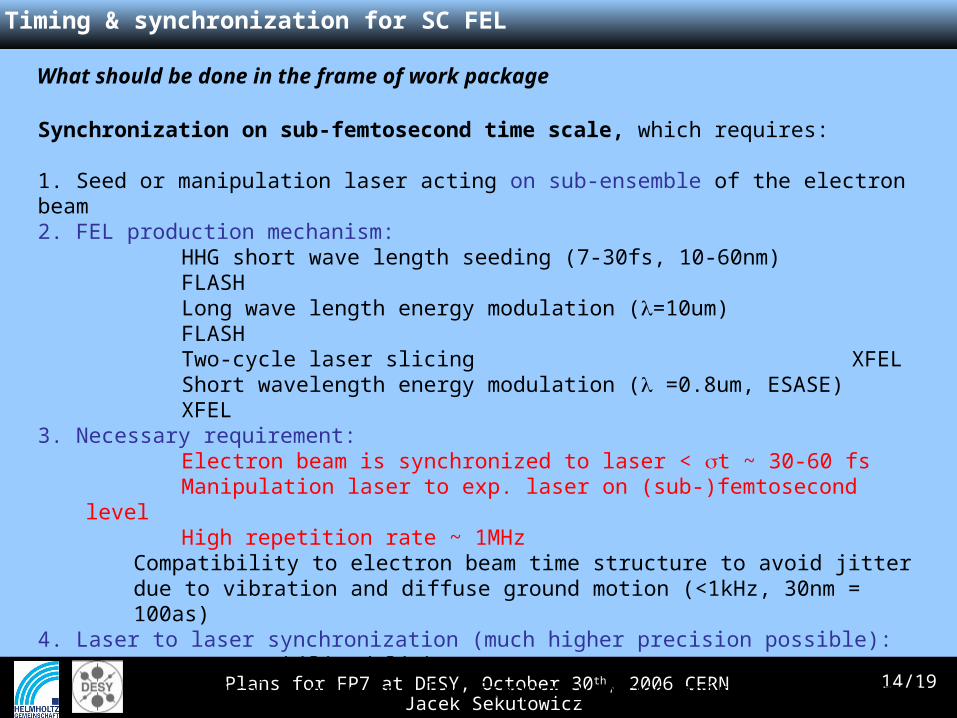
4. Timing & synchronization for SC FEL
Synchronization on sub-femtosecond time scale, which requires:
1. Seed or manipulation laser acting on sub-ensemble of the electron beam 2. FEL production mechanism:
HHG short wave length seeding (7-30fs, 10-60nm) FLASHLong wave length energy modulation (=10um) FLASHTwo-cycle laser slicing XFELShort wavelength energy modulation ( =0.8um, ESASE) XFEL
3. Necessary requirement:Electron beam is synchronized to laser < t ~ 30-60 fsManipulation laser to exp. laser on (sub-)femtosecond levelHigh repetition rate ~ 1MHz
Compatibility to electron beam time structure to avoid jitter due to vibration and diffuse ground motion (<1kHz, 30nm = 100as)
4. Laser to laser synchronization (much higher precision possible):Fceo stabilized linkOptical-clocks for low frequency phase noise stabilization
What should be done in the frame of work package
Plans for FP7 at DESY, October 30th, 2006 CERN Jacek Sekutowicz
15/19
5. Large grain / single crystal Nb resonators
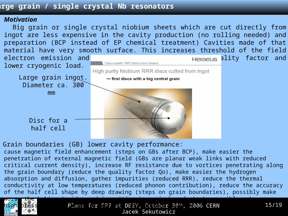
Motivation Big grain or single crystal niobium sheets which are cut directly from ingot are less expensive in the cavity production (no rolling needed) and preparation (BCP instead of EP chemical treatment) Cavities made of that material have very smooth surface. This increases threshold of the field electron emission and potentially leads to higher quality factor and lower cryogenic load.
Large grain ingot. Diameter ca. 300 mm
Disc for a half cell
Grain boundaries (GB) lower cavity performance:cause magnetic field enhancement (steps on GBs after BCP), make easier the penetration of external magnetic field (GBs are planar weak links with reduced critical current density), increase RF resistance due to vortices penetrating along the grain boundary (reduce the quality factor Qo), make easier the hydrogen absorption and diffusion, gather impurities (reduced RRR), reduce the thermal conductivity at low temperatures (reduced phonon contribution), reduce the accuracy of the half cell shape by deep drawing (steps on grain boundaries), possibly make worse the baking (oxides and impurities in grain boundaries), possibly make worse high pressure water rinsing (enhance the surface roughness)

Plans for FP7 at DESY, October 30th, 2006 CERN Jacek Sekutowicz
16/19
5. Large grain / single crystal Nb resonators
What should be done in the frame of work package
Large Grain Niobium (LGN):• Fabrication, preparation (BCP compare to EP) and RF tests of single cell/nine cell cavities from LGN of different suppliers.• Investigation of centrifugal barrel polishing (tumbling) influence on LGN cavity performance• Investigation of the deep drawing peculiarities and shape accuracy in LGN cavities.
Single Crystal Niobium (SCN):• Fabrication, preparation (BCP compare to EP) and RF tests of single cell/ nine cell 1.3/3.9 GHz cavities from SCN• Investigation of the influence of SCN orientation on cavity performance with the aim to define the optimal orientation• Investigation of the SCN orientation influence on electrical, magnetic, thermal, mechanical properties• Investigation of the surface layers covered differently oriented SCN and those influence on the baking procedure• Investigation of electron beam welding conditions, deformation degree and annealing parameters in order to define the conditions allowing not destroy the SCN
Plans for FP7 at DESY, October 30th, 2006 CERN Jacek Sekutowicz
17/19
6. Improvement of the 3.9 GHz higher harmonic system
What should be done in the frame of work packageFLASH will have 1 module with four 9-cell 3.9 GHz cavities manufactured and processed at FNAL, Approx. 36 Cavities needed for the European XFEL. This is too much to be processed at FNAL.Processing and testing facilities are required at DESY.
Motivation Linearization of the bunch phase-space for lower longitudinal emittance and better bunch compression.
Extend the testing infrastructure to allow for preparation of 3.9 GHz Cavities1. BCP treatment2. High-Pressure Rinse3, Cryostat Insert4. RF Equipment / Amplifier 5. Four Cavities for Qualification of Facility
6. Replace 1st iteration module 7. Higher Gradient8. Larger Fill Factor (XFEL Prototype)9. New HOM Coupler

Plans for FP7 at DESY, October 30th, 2006 CERN Jacek Sekutowicz
18/19
7. "LOLA" at 3 GHz-bunch length and longitudinal phase-space measurements
Motivation• Most powerful diagnostics for the longitudinal phase space• At present a 2.856 GHz structure donated by SLAC is used (fill time ~700 ns)
What should be done in the frame of work package
Design changes we have in mind– Change frequency to 3.0 GHz (a harmonic of the M.O. and bunch frequency)– Reduce fill time to below 400 ns (to accommodate 5 MHz bunch repetition rate)

Plans for FP7 at DESY, October 30th, 2006 CERN Jacek Sekutowicz
19/19
8. HOM beam monitors
Motivation HOM can be used as beam position monitors and linac alignment monitors, Very useful for all
sc linear accelerators (FLASH, European XFEL, 4GLS…)
Following Diagnostics can be done with HOMs: – beam position– cavity position and tilt in cryomodule– feedback– phase measurement
What should be done in the frame of work package
• diagnostics• measurement of the axis for various modes, in various cavities; • study of cell misalignment, • cavity deformation• measurement of polarization axis for various modes, in various cavities• other possible studies: coupler kicks, steering effect