Embed Size (px)
Citation preview
© HAROLD ASPDEN, 1997 ENERGY SCIENCE REPORT NO. 7
ENERGY SCIENCE REPORT NO. 7
POWER FROM MAGNETISM: THE TRANSVERSE RELUCTANCE MOTOR
by
© HAROLD ASPDEN, 1997
Contents
Section Title page
Introduction 1
Basic Energy Anomaly 2
A Test Result from the Experimental Motor 7
Test Result Significance 13
Test Machine Description 16
Supplementary Commentary 18
APPENDIX I: LC Circuit Loss Analysis 22
APPENDIX II: Machine Description in Patent Specification 24-40
******
THE TRANSVERSE RELUCTANCE MOTOR
© HAROLD ASPDEN, 1997 ENERGY SCIENCE REPORT NO. 7
POWER FROM MAGNETISM: THE TRANSVERSE RELUCTANCE MOTOR
Introduction
This Energy Science Report is Part I of a research report documenting progress ona project funded by the U.K. Department of Trade and Industry as a Stage I SMARTAWARD*. This was awarded in August 1994 to Thermodynamics Limited in an opencompetition based on an invention submission by the author. The object of the researchis to establish whether or not a magnetic reluctance motor can derive any of its power bytapping the thermodynamic field background and the proposal suggested a novel form ofmotor construction with this objective.
At this interim report stage (May, 1995) tests on an experimental machine give apreliminary indication that such thermal effects, which involve magnetocaloric cooling,do exist and account for the enhanced efficiency anomalies observed. This machine,which has technological features hitherto unexplored and which meant that its design issomewhat of an exploratory nature, provides the evidence needed to design a viableprototype demonstration machine system. The latter should now progress on a muchshorter time scale and will be the basis of the Part II report.
The content of this report will not relate to the many problems that beset thisproject in its initial period, nor to the spin-off research findings, which also have a specialinterest, nor to the different machine constructions explored en route. What will bedisclosed is:
(a) The author's original reasons for expecting a thermodynamic power gainin the pursuit of this project,
(b) The experimental evidence supporting the above proposition as derivedfrom detailed analysis of one set of test results on the primary machine and
(c) The constructional features of that machine which will also be the basis ofthe onward design of the prototype to be tested for the next Report.
The tentative conclusion emerging from what is here reported is that we can hopeto see a way forward to magnetic reluctance motor development which brings in sight thepossibility of generating electrical power by tapping the ambient thermodynamic fieldbackground. Success in such a venture would bring with it a much-needed new non-polluting energy resource.
_______
* "Small Firms Merit Award for Research and Technology.
THE TRANSVERSE RELUCTANCE MOTOR2
© HAROLD ASPDEN, 1997 ENERGY SCIENCE REPORT NO. 7
Basic Energy Anomaly
It is hoped that technical specialists reading this report will not prejudge thefindings by believing, inappropriately, that the Second Law of Thermodynamics appliesto this particular technology. This preliminary section gives a background introductionto the scientific principles underlying the work, including comment on its thermodynamicprinciples.
The magnetic reluctance motor differs in operating principle from normal d.c. ora.c. motors in that it relies upon magnetic induction, a process which involves storingenergy in gaps between magnetic poles. The more familiar electromagnetic machineoperates by passing current through windings which are acted upon by magnetic poles toset up the drive force causing machine rotation. In the reluctance motor it is the releaseof energy from the pole gaps as they close that feeds the drive power to the machine.
When we consider how a d.c. voltage power supply is used to feed that priminginduction energy to the reluctance motor the equivalent circuit is seen to be one havingwinding resistance R and inductance L connected in series to a supply providing an EMFE resulting in a current I.
By applying standard electrical theory it is an easy task to calculate the proportionof energy input that goes into the I2R losses and the proportion LI2/2 that is stored byinductance. Their ratio changes as the current builds up and would become extremelylarge if the flow were allowed to continue long enough in its effort to reach the ultimatevalue Io of E/R.
However, as in the reluctance motor, we commutate the flow, allowing just enoughinductance energy into the machine to give it the drive power before switching the currentoff. The time period involved need not therefore be any greater than 25% of the periodof the magnetic flux cycle resulting from successive pole gap closure and separation, thisbeing determined by the synchronous frequency of the machine. For the 8-pole machinetest reported later this becomes 1/200 second at 50 Hz and 375 rpm. At 1500 rpm the 25%duty cycle would be of 1/800 second duration.
Even though these time periods are short, the design of the machine has to be suchthat a sufficient input energy can reach that inductance in that short time and that meansthat the winding resistance has to be low.
However, a design compromise is needed here. It might seem reasonable to requireoperation for which that charging time period is of the same order as the time constant ofthat inductive circuit, namely L/R seconds, thinking that if this were not so then the fullinductance of the machine would not be harnessed to give the machine its best powerrating.
The question at issue, is the amount of the loss in the resistance in relation to theenergy fed to inductance.
THE TRANSVERSE RELUCTANCE MOTOR 3
© HAROLD ASPDEN, 1997 ENERGY SCIENCE REPORT NO. 7
For an ongoing power input rate simple calculation (see Appendix) gives this ratioas a function of time as:
eRt/L - 1 (1)
which at the end of the period θ defined by the time constant L/R becomes e-1 or 1.718.This means that only 37% of the power input at the end of this period can be finding itsway into the drive of the machine, because 63% is being lost.
As shown in the Appendix if the cumulative energy input during that time periodL/R is calculated, based on a linear inductance assumption, then 54% finds its way into thepower drive and 46% is lost in that resistance R.
Of course, if, as is the case, the inductance increases as the poles of the machineclose this will progressively shorten the relevant time period in (1) and reduce theproportion representing loss, but it would still seem surprising that there could be areduction of an overall loss percentage to 10% or even 20%.
Yet, as is well established, magnetic reluctance motors can operate in the 80-90%efficiency range, even taking into account magnetization losses in their core structures.
This can be explained by the design expedient of putting a strong input EMF onthe motor winding so that the input pulses develop a rapid rate of change of the magneticflux accounting for the inductive energy input. This develops a back EMF which leaveslittle potential drop across the low resistance of the winding. The pulse period must thenbe much shorter than the time constant L/R, so that the current is switched off before themagnetic circuit begins to saturate. This is tantamount also to using a very low resistancewinding, an awkward design constraint if the coils forming that winding have to fit onsalient poles.
Modern electronic switching technology, which in itself brings with it another formof loss, has progressed to the point where the expense of the current pulsing makes themagnetic reluctance motor a viable alternative to the normal a.c. induction motor. Evenso,we need to look at ways of developing the reluctance motor further, not only with thatwinding resistance and the L/R factor in mind but also with regard to the followingargument concerning a thermodynamic factor.
Given the high efficiencies obtained by reluctance motors and accepting thatdesigners will know precisely where the loss occurs, there is really no fully justifiablebasis for suggesting that existing magnetic reluctance motor technology may be alreadyderiving benefit from a magnetocaloric energy regeneration effect. However, this authordoes wonder if, marginally at least, such an effect is already assisting motor performance.
THE TRANSVERSE RELUCTANCE MOTOR4
© HAROLD ASPDEN, 1997 ENERGY SCIENCE REPORT NO. 7
If a pulse duration period commensurate with the circuit time constant L/R wereto be used and the I2R losses were 50% of motor input power, then to regain the 90% levelof efficiency the inductance energy would need to be augmented by the equivalent of 40%of motor input from the quantum field background. The latter governs the atomic electronquantization in the ferromagnetic state in iron and plays a key role in magnetocaloriccooling.
In this case, the flux recovery cycle of the machine would result in environmentalcooling within that field system and this would draw on the heat generated in theresistance to gave the overall appearance of an efficient motor. So here might be animportant technological phenomenon that we may, in some small measure, be usingunknowingly in our reluctance motors, but one we could use to much more advantage ifit were researched and well understood.
The author, therefore, has had occasion to examine more closely what is of recordin university teaching concerning how energy is stored in an air gap in a magnetic circuit.
The author's Ph.D. thesis had concerned anomalous energy losses in iron based onresearch (1950-1953) in Professor E.B. Moullin's Department of Electrical Engineeringat Cambridge and one needs to look no further than a textbook by Professor Moullin. Onpages 172-174 of his 'Principles of Electromagnetism', (Clarendon Press, Oxford, 1955),an experiment is reported which describes the inexplicable aspects of apparent magneticflux linkage between two magnetic cores separated by an air gap. The teaching conclusionwas that leakage flux defies calculation when one tries to theorize about experimentalresults.
This author, having developed suspicions about the thermodynamic aspectsdiscussed above, has come, many years later to see the Moullin experiment with new eyes.The evidence is clearly there indicating that the energy in the air gap is greater than theenergy supplied as inductive input to the magnetizing winding, greater by a factor thatincreases with increasing magnetic flux density.
This led the author, in the first of these Energy Science Reports, to describe andreport findings on an experiment based on that performed by Professor Moullin, in orderto confirm this position. That experiment involved a sequence of tests on static cores withsuccessively different air gap spacings and has been reported by this author to a conferenceon the new energy topic held in Denver, Colorado. It has since been repeatedindependently by others, all of whom confirm that there is a significant energy gain.
The magnetic reluctance motor is the device one turns to if one wishes to use thatexcess energy before it is recaptured by the magnetic core system during the reset period.It was this background that inspired the inventive concepts which are now under test inthis SMART AWARD project.
THE TRANSVERSE RELUCTANCE MOTOR 5
© HAROLD ASPDEN, 1997 ENERGY SCIENCE REPORT NO. 7
To end this introductory section, and before moving on to present test data on theexperimental motor, a few words concerning the Second Law of Thermodynamics areappropriate.
This law is based on the doctrine of the impossible, namely that one cannot takeheat from a source and convert it into useful power in a machine unless that source shedsheat to an absorbing medium at lower temperature. Now, in a magnetic core, or in an airgap between magnetic poles, there is an activity that accounts for energy storage byinductance. That activity involves electric charge in motion and reacting to the appliedfield. That reacting charge is kept active by thermal motion, whether this be mere thermalnoise in the magnetic circuit seated in conduction electrons or whether, as applies in thevacuum gap, that 'noise' is and the quantum activity known to physicists as 'zero-point'field energy. If energy is fed by machine excitation into that inductance then the energysupplied, whether driven by current in a magnetizing winding or augmented by theferromagnetic core it embraces, must be pooled with that thermal energy. It is shed asheat. Then, when the demagnetization process occurs or the pole gap closes to reduce theinductive energy stored, so there is cooling as energy is used to do work. The latter maybe by setting up an EMF in the magnetizing winding or by mechanical work derived fromthe force action between the poles, but this thermodynamic activity is an ongoing andessential part of the physical property we describe as inductance. Its return is not by arandom heat diffusion process, simply because the applied magnetic field set up by currentin a winding brings order into the reacting charge motion and orientates its vector inreadiness for an eventual collapse directed into the winding as a back EMF.
Electrical science does not ascribe temperature to the field energy stored byinduction. Accordingly, scientists reading this will not be familiar with this summarydescription. However, no reasonable scientist could assert that this process is in any wayrestrained by a need to comply with the Second Law of Thermodynamics. The latter onlyconcerns true heat engines that operate between set temperature limits and not to machineswhich know only one temperature, the ambient temperature, and in which magnetism isthe catalyst converting heat into electricity.
This latter statement needs just a little qualification because MHD technology issubject to the Carnot efficiency limitations, MHD being the magnetohydrodynamictechnology of the 1960 period, in which ionized gas passes through a transverse magneticfield which cools the gas to develop an EMF producing electrical output in the mutuallyorthogonal direction.
Here, the heat is that of ions in a gas and the gas emerges at a lower temperaturethan at entry. If we consider instead the energy associated with the motion of freeelectrons in metals or the charges that sustain displacement currents in the field mediumof space, then that temperature property, so far as it concerns the hidden charge reactingto the inductive field becomes at best something that is notional and unrelated to thetemperature of a machine proper. That hidden charge, whether in the system of freeelectrons or in the zero-point field of the vacuum medium, becomes the 'prime mover'
THE TRANSVERSE RELUCTANCE MOTOR6
© HAROLD ASPDEN, 1997 ENERGY SCIENCE REPORT NO. 7
reacting to shed heat energy to sustain the EMFs regenerating useful power frominductance and recovers heat by cooling the surrounding atoms in the machine structure.
To use the Second Law of Thermodynamics to argue against this, one mustcontend that there are two temperatures and assign a temperature to the 'prime mover' thatdiffers from the ambient temperature of the machine. The 'prime mover', however, in iron,for example, is the free electron population and one is told in physics that such electronshave very high Fermi velocities and so are, notionally, kept at very high temperatures. Ifsuch temperatures are so high, they are higher both for inward transfer of inductive energyand the later return of that energy. The Second Law of Thermodynamics can only applyto one way energy transfer but inductance is a two-way phenomenon, as we well knowfrom the highly tuned resonant oscillatory conditions that can be established in inductivecircuits.
Even by normal equipartition of energy rules concerning particle collisions withinthe iron core, the free electrons we need to account for electrical conduction are kept inmotion at higher effective temperatures than the surrounding atoms.
One can, therefore, argue that the Second Law of Thermodynamics has to beconfined to the machines such as steam engines and internal combustion engines and notapplied to the inductive properties of the reluctance motor. This is in spite of the fact thatthe latter do involve thermodynamic energy processes.
Unquestionably, however, the doctrinaire attitude of academic physicists on thisquestion of the Second Law of Thermodynamics has precluded acceptance of this author'slong standing explanation of electromagnetic induction and related gyromagnetic reactionphenomena.
Enough has been said for the moment on this scientific debate and this Report neednot take the argument further. What matters is the experimental evidence reported in thenext section. The real purpose of this Part I introductory discourse has been to argue thatthe thermodynamic foundations of the invention to be described are on very firm groundand can be traced by survey of this author's work of published record in scientificperiodicals and books.
THE TRANSVERSE RELUCTANCE MOTOR 7
© HAROLD ASPDEN, 1997 ENERGY SCIENCE REPORT NO. 7
A Test Result from the Experimental Motor
The design and construction of the motor will form the subject of a followingsection. Here it suffices to state that the motor has two magnetizing windings which areinductively coupled, the excitation of which can switch the magnetism of a permanentmagnet between a path through the pole gaps to develop drive torque or a leakage pathwhere no torque is developed. The intention is that the magnets will do the work neededto drive the motor, buffering energy through inductance, and absorbing ambient heat toreplenish that shed by the magnets, with applied electrical input power serving essentiallyto control flux switching.
As will be seen the design precludes any torque reaction from normalelectrodynamic effects between current in the magnetizing windings and magnetic flux inthe machine, thereby restricting any motor drive to a true magnetic reluctance actionseated in the inductive field energy. The reason is that all conductor turns on the windings,to the extent that they are linked by magnetic leakage flux, can only assert forces indirections that are radial with respect to the machine axis.
As a summary statement, the test to be described gives reason to believe that thethermodynamic efficiency gain predicted as a basis for the project has been confirmed.It remains now to build a prototype machine and a new control system designed to a moreeffective specification which can now be formulated from the data provided by this test.
Note that, so far as this test result is concerned, emphasis is placed upon theestablishment of the principle that a magnetic reluctance motor can operate with anefficiency enhanced by magnetocaloric cooling, the ultimate hope being to secure evidenceof 'over-unity' performance. By 'over-unity' is meant a mechanical output powerexceeding the electrical input power owing to thermodynamic input involvingenvironmental cooling.
The dominant pursuit, the focus of the SMART AWARD, has however been theless ambitious aim at a modest efficiency improvement by investigating the possibility ofself-commutation by a 'shaded-pole' construction of unusual design which has similarthermodynamic implications.
Both technical objectives have been served by the same test machine. Noteparticularly that this 'self-commutation' objective explains why the machine has noconventional commutator, a feature which has made the broader scope of the researchtesting of the machine particularly difficult.
The test reported here was a no-load test in the sense that the only mechanicalfunction was that of running both a drive motor and the test machine as a mechanically-coupled system. The task is the assessment of the inherent operational electrical andmechanical characteristics of the test machine. This latter has a very special and unusual
THE TRANSVERSE RELUCTANCE MOTOR8
© HAROLD ASPDEN, 1997 ENERGY SCIENCE REPORT NO. 7
design configuration which has made it impossible to use standard electrical engineeringknowledge to make a reliable prediction of its response to applied power.
Besides this, as can be seen from the opening text of this section, there are certaincomplexities in the magnetic circuit form, which includes permanent magnets, and the polegap configuration as well as end effects, not to mention eddy-current reactions. All thesepose unusual design considerations, involving non-linear characteristics and non-harmonictime characteristics, and so are best explored empirically.
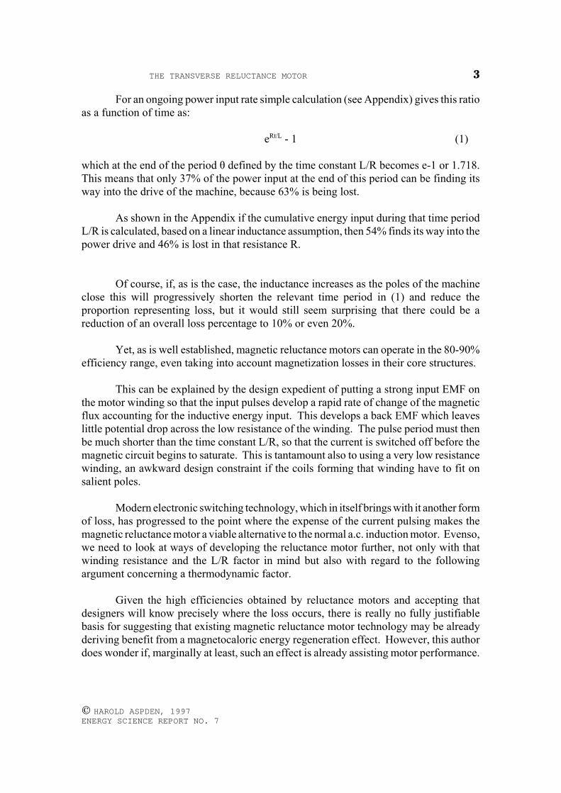
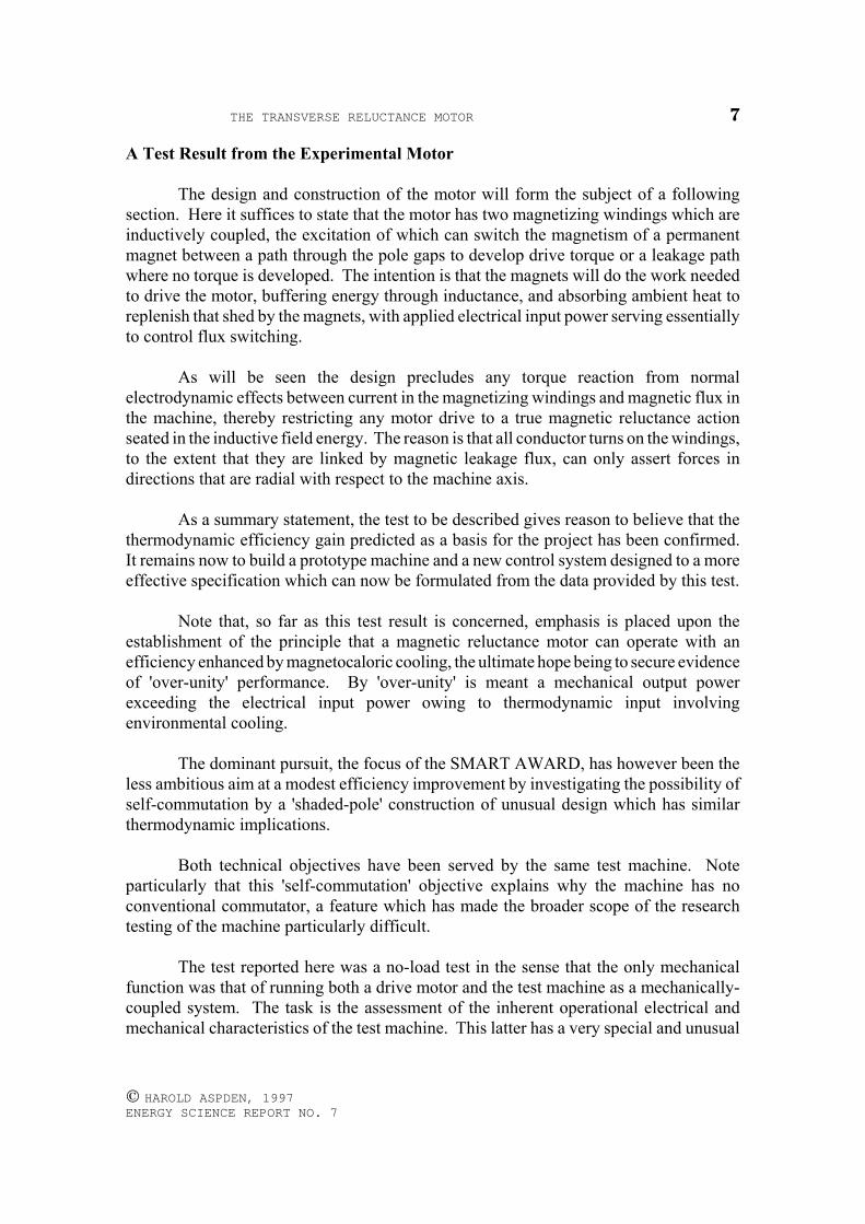
The Equivalent Circuit of the Test Configuration
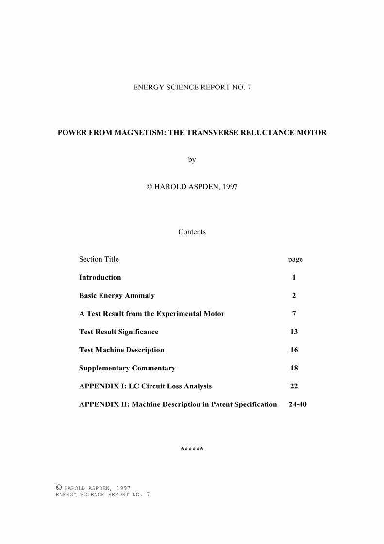
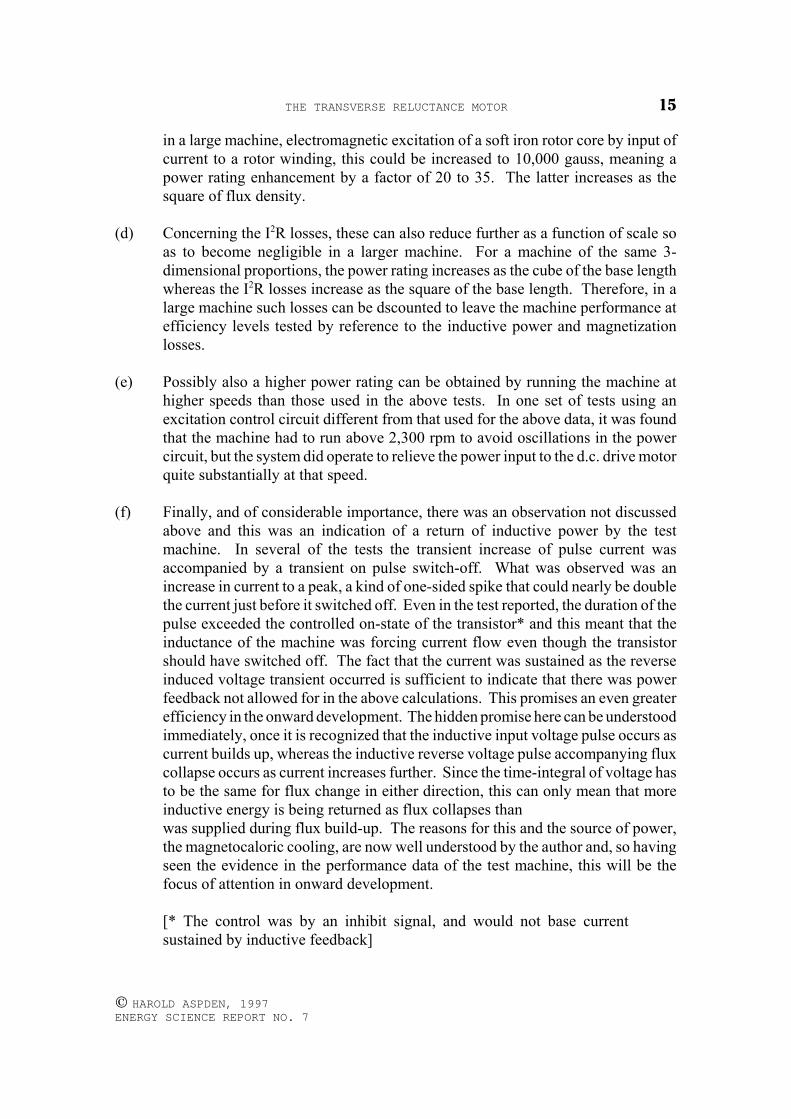
This is shown in Fig. 1 where the two machines are depicted by the broken line ashaving mechanically coupled shafts and each machine has its own circuit powered by astabilized d.c. voltage supply.
The d.c. drive motor has a permanent magnet stator system and rotor windings fedas a single input through a commutator incorporated in the machine. It has a high torqueand a maximum speed rating of 5,100 rpm when driven by a 12 volt d.c. supply, itsmaximum power rating being 65 watts.
Fig. 1
[Note that as the research developed, the 'shaded-pole' feature wasimplemented by providing laminated stator cores, which were mounted inthe motor in a 'transverse' sense and were tilted in the forward direction ofrotor spin. The word 'transverse' means that they were arranged to act in across-wise direction. This explains the title of this Report.]
THE TRANSVERSE RELUCTANCE MOTOR 9
© HAROLD ASPDEN, 1997 ENERGY SCIENCE REPORT NO. 7
It was chosen because the cogging effect owing to the the stepping action of thepole structure of the test machine showed the need for a good drive torque, but evenso thesystem had to be given a hand-start by bringing the poles out-of-register when the d.c.motor was started up. This requirement will be avoided in the onward construction of theprototype machine.
Vm was measured by a digital voltmeter (d.c. scale) and its waveform observed onan oscilloscope.
Vi was also observed as a waveform on an oscilloscope.
The machine speed was measured using an optical tachometer.
The 2.2Ω and 2.6Ω external resistors were included as load devices to bufferpotential drop and, in the case of the d.c. motor, to allow its power supply to remainunadjusted whilst the motor changed speed during the test.
The 0.65Ω resistance was the measured internal resistance of the d.c. drive motorwinding, whereas the windings on the test machine had a 2.6Ω resistance.
Test Machine not Excited
The drive motor was run coupled to the test machine at 800 rpm and id was foundto be 1.03 amps with Vd of 5.5V.
Total power input: (5.5)(1.03) 5.665 wattsPower in 2.2Ω load: (2.2)(1.03)2 2.334 watts Power supplied to motor: 3.331 wattsLoss in 1.2Ω winding: (0.65)(1.03)2 0.690 wattsDrive power to system: 2.641 watts
After the system had been operated with the above voltage input but with the testmachine excited the following further measurement at higher input voltage with the testmachine non-excited was performed at higher speed.
The drive motor was run coupled to the test machine at 1350 rpm and id was foundto be 1.15 amps with Vd of 7.1V.
Total power input: (7.1)(1.15) 8.165 wattsPower in 2.2Ω load: (2.2)(1.15)2 2.910 watts Power supplied to motor: 5.255 wattsLoss in 0.65Ω winding: (0.65)(1.15)2 0.860 wattsDrive power to system: 4.395 watts
THE TRANSVERSE RELUCTANCE MOTOR10
© HAROLD ASPDEN, 1997 ENERGY SCIENCE REPORT NO. 7
Test Machine Excited
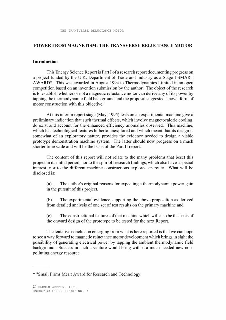
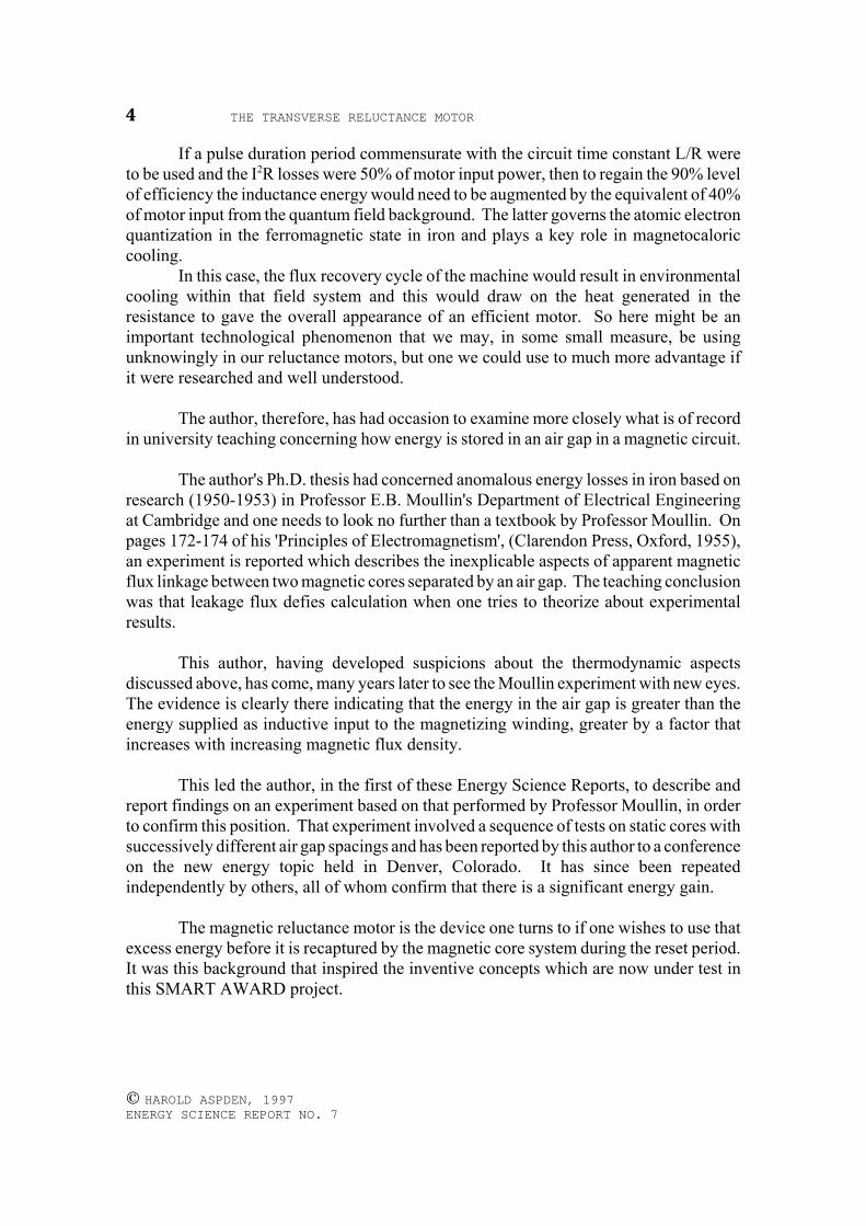
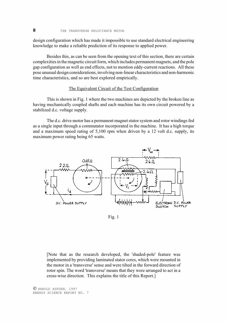
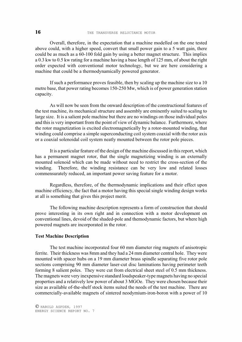
Vd was held at 5.5V and the test machine now powered by adjusting a regulatingpotentiometer controlling a power transistor used as a switch, avoiding an oscillationmode, to result in a Vm waveform of the form shown in Fig. 2. The d.c. supply voltage tothe transistor circuit was 12.26V.
Fig. 2
Note that the trace showed an upward surge just before the current ceased. Thiswill be explained later, but for the immediate purpose we will interpret the waveform asbeing a rectangular pulse with an initial exponential transient, such as one expects fromswitching a d.c. step voltage into an inductance. Note that Vm as a voltage is really ameasure of current in a 2.6Ω load resistor.
The measured d.c. average of this voltage waveform was 1.31V and the machineran on this setting at 1350 rpm with the drive motor current id having reduced to 0.64amps.
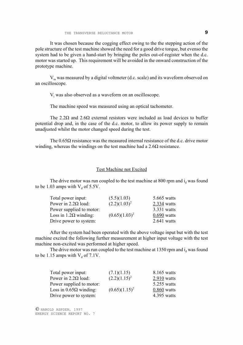
From the waveform it was estimated that the switched-on duty cycle of the testmachine was 60% and it was clear that the exponential rise in the signal represented theinductive power input needed to sustain magnetization loss and the true drive power fedto the test machine, whereas most of the power was dissipated in the I2R loss of the loadresistance and the machine winding as well as by potential drop in the power transistorused for this test.
This 60% duty cycle was longer than had been intended but it did serve to give aresult as control settings providing such pulse duration were found more effective than theshorter pulses obtained by biasing the control. However, this is most certainly onlybecause the timing of pulse onset was not optimally set owing to a weakness in theelectronic circuit design used and this, too, will be overcome once the main prototypemachine system is built. Such redesisgn will avoid reliance on the close magneticcoupling of the power input winding and the winding used to produce the commutatingcontrol signal.
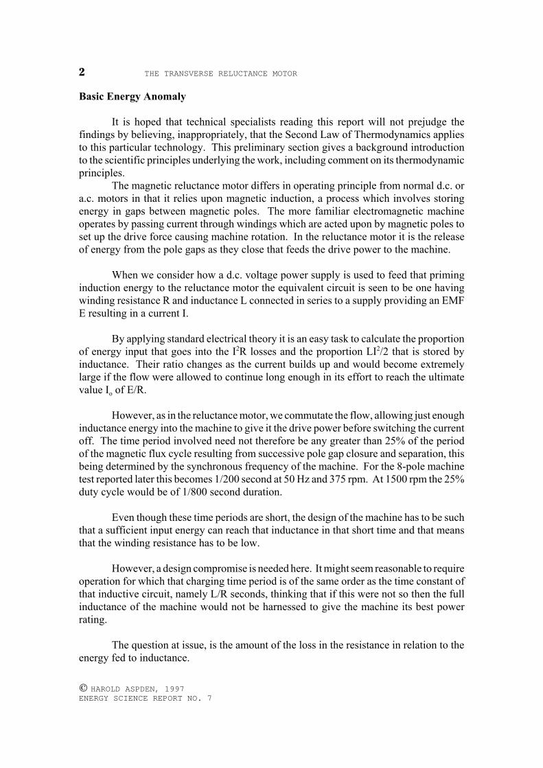
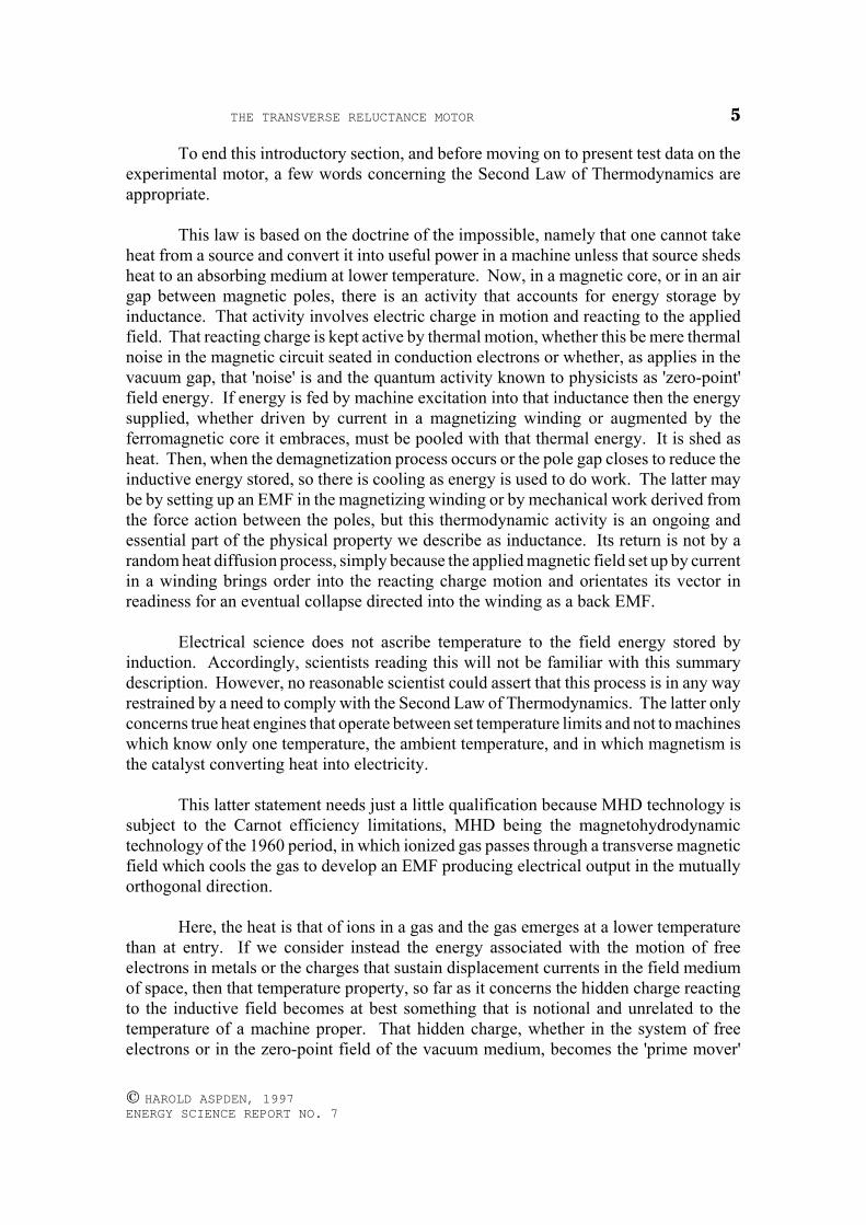
Fig. 3
THE TRANSVERSE RELUCTANCE MOTOR 11
© HAROLD ASPDEN, 1997 ENERGY SCIENCE REPORT NO. 7
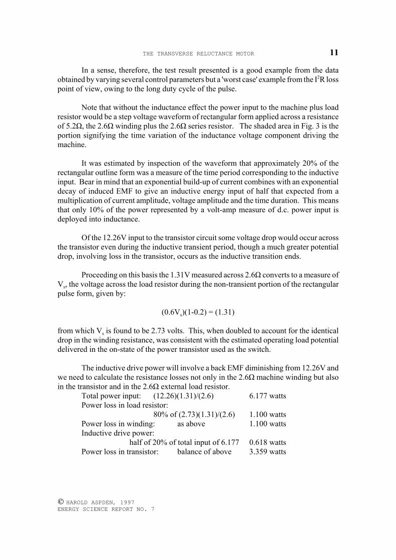
In a sense, therefore, the test result presented is a good example from the dataobtained by varying several control parameters but a 'worst case' example from the I2R losspoint of view, owing to the long duty cycle of the pulse.
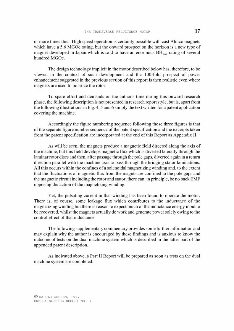
Note that without the inductance effect the power input to the machine plus loadresistor would be a step voltage waveform of rectangular form applied across a resistanceof 5.2Ω, the 2.6Ω winding plus the 2.6Ω series resistor. The shaded area in Fig. 3 is theportion signifying the time variation of the inductance voltage component driving themachine.
It was estimated by inspection of the waveform that approximately 20% of therectangular outline form was a measure of the time period corresponding to the inductiveinput. Bear in mind that an exponential build-up of current combines with an exponentialdecay of induced EMF to give an inductive energy input of half that expected from amultiplication of current amplitude, voltage amplitude and the time duration. This meansthat only 10% of the power represented by a volt-amp measure of d.c. power input isdeployed into inductance.
Of the 12.26V input to the transistor circuit some voltage drop would occur acrossthe transistor even during the inductive transient period, though a much greater potentialdrop, involving loss in the transistor, occurs as the inductive transition ends.
Proceeding on this basis the 1.31V measured across 2.6Ω converts to a measure ofVs, the voltage across the load resistor during the non-transient portion of the rectangularpulse form, given by:
(0.6Vs)(1-0.2) = (1.31)
from which Vs is found to be 2.73 volts. This, when doubled to account for the identicaldrop in the winding resistance, was consistent with the estimated operating load potentialdelivered in the on-state of the power transistor used as the switch.
The inductive drive power will involve a back EMF diminishing from 12.26V andwe need to calculate the resistance losses not only in the 2.6Ω machine winding but alsoin the transistor and in the 2.6Ω external load resistor.
Total power input: (12.26)(1.31)/(2.6) 6.177 wattsPower loss in load resistor:
80% of (2.73)(1.31)/(2.6) 1.100 wattsPower loss in winding: as above 1.100 wattsInductive drive power:
half of 20% of total input of 6.177 0.618 wattsPower loss in transistor: balance of above 3.359 watts
THE TRANSVERSE RELUCTANCE MOTOR12
© HAROLD ASPDEN, 1997 ENERGY SCIENCE REPORT NO. 7
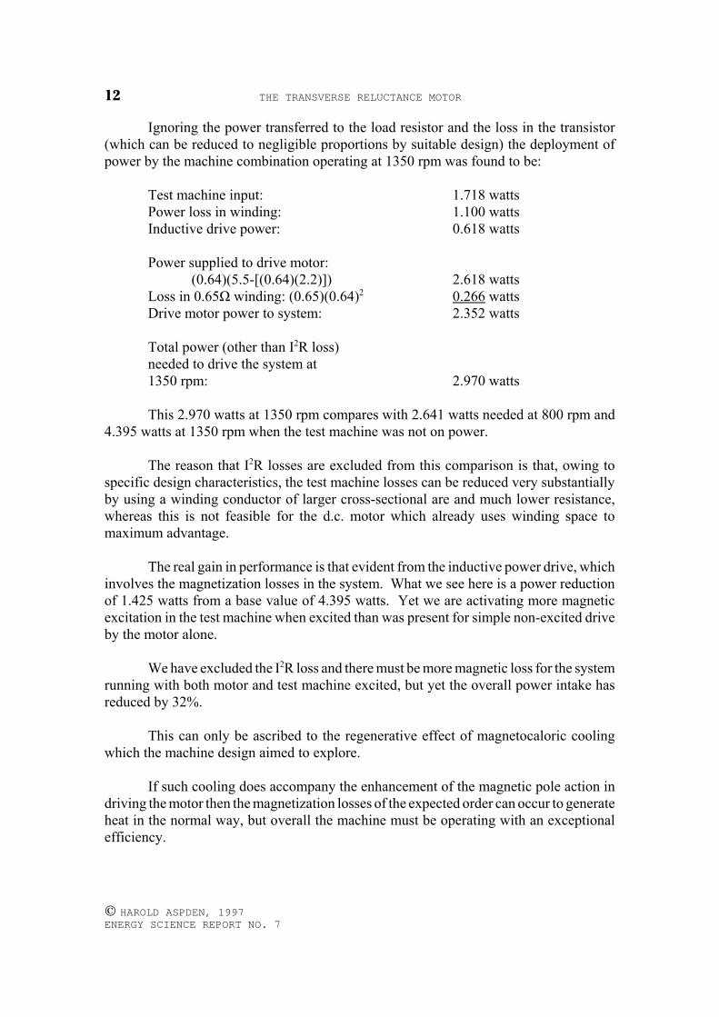
Ignoring the power transferred to the load resistor and the loss in the transistor(which can be reduced to negligible proportions by suitable design) the deployment ofpower by the machine combination operating at 1350 rpm was found to be:
Test machine input: 1.718 wattsPower loss in winding: 1.100 wattsInductive drive power: 0.618 watts
Power supplied to drive motor:(0.64)(5.5-[(0.64)(2.2)]) 2.618 watts
Loss in 0.65Ω winding: (0.65)(0.64)2 0.266 wattsDrive motor power to system: 2.352 watts
Total power (other than I2R loss)needed to drive the system at1350 rpm: 2.970 watts
This 2.970 watts at 1350 rpm compares with 2.641 watts needed at 800 rpm and4.395 watts at 1350 rpm when the test machine was not on power.
The reason that I2R losses are excluded from this comparison is that, owing tospecific design characteristics, the test machine losses can be reduced very substantiallyby using a winding conductor of larger cross-sectional are and much lower resistance,whereas this is not feasible for the d.c. motor which already uses winding space tomaximum advantage.
The real gain in performance is that evident from the inductive power drive, whichinvolves the magnetization losses in the system. What we see here is a power reductionof 1.425 watts from a base value of 4.395 watts. Yet we are activating more magneticexcitation in the test machine when excited than was present for simple non-excited driveby the motor alone.
We have excluded the I2R loss and there must be more magnetic loss for the systemrunning with both motor and test machine excited, but yet the overall power intake hasreduced by 32%.
This can only be ascribed to the regenerative effect of magnetocaloric coolingwhich the machine design aimed to explore.
If such cooling does accompany the enhancement of the magnetic pole action indriving the motor then the magnetization losses of the expected order can occur to generateheat in the normal way, but overall the machine must be operating with an exceptionalefficiency.
THE TRANSVERSE RELUCTANCE MOTOR 13
© HAROLD ASPDEN, 1997 ENERGY SCIENCE REPORT NO. 7
The test, as interpreted above, does establish that there is an anomalous excesspower phenomenon at work.
Test Result Significance
The tests were made with the test machine rotating clockwise, which was thedirection corresponding to the shaded-pole construction of the stator pole pieces.Anticlockwise rotation for the same input power conditions gave speeds some 10% belowthose measured for clockwise rotation.
Therefore this feature, in aiding commutation, is contributing to machineperformance and will now be accentuated further in the onward construction of theprototype machine.
This prototype version of the machine will be designed to overcome the testdifficulties encountered in the pulse control of the machine as tested above. The testssuffered from the problem of correctly timing the onset of the pulse current and itsduration. When the design parameters of such a control could be ascertained from the testsit became apparent that the best way forward was to design instead a machine having adual excitation so as to avoid the inductive coupling of the single excitation which set upunwanted oscillations and so limited scope for full power testing.
The machine had a size and weight commensurate with a normal motor of severalhundred watts rating and yet was tested at 1350 rpm, taking a coupled d.c. motor up to thatspeed from a base speed of 800 rpm, with only 0.329 watts of additional input drivepower! This excludes the power needed to sustain I2R losses in the windings of the twomachines, but the corresponding increment in such power was only 0.676 watts. Theabove data show 0.690 watts as drive motor winding loss at 800 rpm, 1.100 watts as lossin the test machine winding at 1350 rpm and 0.266 watts loss in the drive motor windingunder combined operational conditions at the latter speed.
As is explained below, the latter losses can be very substantially reduced but theprime attention has to focus first upon the thermodynamic implications to clarify a verybasic issue.
The question at issue is whether one can be 100% sure that the machine is actingregeneratively in a thermodynamic sense. There is every indication that it is, but there isone open question that is crucial to scaling up the design to a high power machine.
The answer to the question will decide whether this research is leading to a newmachine technology of highly efficient motors, which can, as it were, feed on the heat theygenerate and so come close to being 100% efficient or whether it can lead to a technologybreakthrough of far greater importance.
THE TRANSVERSE RELUCTANCE MOTOR14
© HAROLD ASPDEN, 1997 ENERGY SCIENCE REPORT NO. 7
There is good reason, by reference to the Moullin-type of experiment alreadymentioned, to suspect that we can draw on energy feeding the underlying quantum fieldthat powers the atomic spins in a ferromagnet. If this is so then the magnetocaloriccooling process has much more to offer than the near-to-100% efficient electric motor. Insight comes the possibility of building a new form of power generator.
In other tests on the same machine system as that discussed above it was found thatincreased current input to the test machine could reduce the d.c. drive motor current to 0.2amp, less than 20% of its normal value, but it was not possible with the particular test rigused to run the system with only the test machine on power.
The objective there was to see if one might reach a stage where the d.c. motorcurrent reversed as it became a generator. Then one could explore the degree to whichmagnetocaloric cooling can be exploited in a power generation mode.
Clarification of this issue will be the objective of the Part II Report which willfollow from tests on the prototype machine now under construction.
In the meantime, the following technical points emerging from the above testfindings are to be noted:
(a) The I2R losses attributable to the test machine winding can be reduced by a factorof 5 at least, because it should be possible to limit the inductive power input to lessthan 40% of the pulse period used in the test and because a single winding of 2.6Ωwas used instead of two such windings in series driven at half current. The secondwinding was deployed, contrary to original design intention, to provide thecommutating signal control for the electronic switch and the pulse period waslonger than it should have been and its onset poorly timed owing to control settingsadjusted to avoid feedback-induced oscillations. The latter problems can easily beeliminated with a dual test machine combination. The machine design wouldallow the winding resistance to be reduced very substantially if the weight and costof the copper could be justified by the efficiency gain.
(b) The use of only 4 magnets in the test machine may mean that end effects whichweaken the operation owing to magnetic leakage can be present. These can bereduced relatively by using more magnets and a longer rotor axis. The latter wasaccepted as a limitation in the design of the first machine, dictated by availabilityof stator pole pioece laminations, but the findings now warrant building the longermachine. More magnets on a longer stator with the pole gap spacing halvedshould give power enhancement by a factor of 3 or more, without appreciablychanging the overall size of the machine.
(c) The magnets used in the machine tested above developed a flux density in thestator having an a.c. RMS value of between 600 and 800 gauss, which implies aunidirectional polarization of 1700 to 2260 gauss. By using stronger magnets or,
THE TRANSVERSE RELUCTANCE MOTOR 15
© HAROLD ASPDEN, 1997 ENERGY SCIENCE REPORT NO. 7
in a large machine, electromagnetic excitation of a soft iron rotor core by input ofcurrent to a rotor winding, this could be increased to 10,000 gauss, meaning apower rating enhancement by a factor of 20 to 35. The latter increases as thesquare of flux density.
(d) Concerning the I2R losses, these can also reduce further as a function of scale soas to become negligible in a larger machine. For a machine of the same 3-dimensional proportions, the power rating increases as the cube of the base lengthwhereas the I2R losses increase as the square of the base length. Therefore, in alarge machine such losses can be dscounted to leave the machine performance atefficiency levels tested by reference to the inductive power and magnetizationlosses.
(e) Possibly also a higher power rating can be obtained by running the machine athigher speeds than those used in the above tests. In one set of tests using anexcitation control circuit different from that used for the above data, it was foundthat the machine had to run above 2,300 rpm to avoid oscillations in the powercircuit, but the system did operate to relieve the power input to the d.c. drive motorquite substantially at that speed.
(f) Finally, and of considerable importance, there was an observation not discussedabove and this was an indication of a return of inductive power by the testmachine. In several of the tests the transient increase of pulse current wasaccompanied by a transient on pulse switch-off. What was observed was anincrease in current to a peak, a kind of one-sided spike that could nearly be doublethe current just before it switched off. Even in the test reported, the duration of thepulse exceeded the controlled on-state of the transistor* and this meant that theinductance of the machine was forcing current flow even though the transistorshould have switched off. The fact that the current was sustained as the reverseinduced voltage transient occurred is sufficient to indicate that there was powerfeedback not allowed for in the above calculations. This promises an even greaterefficiency in the onward development. The hidden promise here can be understoodimmediately, once it is recognized that the inductive input voltage pulse occurs ascurrent builds up, whereas the inductive reverse voltage pulse accompanying fluxcollapse occurs as current increases further. Since the time-integral of voltage hasto be the same for flux change in either direction, this can only mean that moreinductive energy is being returned as flux collapses than was supplied during flux build-up. The reasons for this and the source of power,the magnetocaloric cooling, are now well understood by the author and, so havingseen the evidence in the performance data of the test machine, this will be thefocus of attention in onward development.
[* The control was by an inhibit signal, and would not base currentsustained by inductive feedback]
THE TRANSVERSE RELUCTANCE MOTOR16
© HAROLD ASPDEN, 1997 ENERGY SCIENCE REPORT NO. 7
Overall, therefore, in the expectation that a machine modelled on the one testedabove could, with a higher speed, convert that small power gain to a 5 watt gain, therecould be as much as a 60-100 fold gain by using a better magnet structure. This impliesa 0.3 kw to 0.5 kw rating for a machine having a base length of 125 mm, of about the rightorder expected with conventional motor technology, but we are here considering amachine that could be a thermodynamically powered generator.
If such a performance proves feasible, then by scaling up the machine size to a 10metre base, that power rating becomes 150-250 Mw, which is of power generation stationcapacity.
As will now be seen from the onward description of the constructional features ofthe test machine, its mechanical structure and assembly are eminently suited to scaling tolarge size. It is a salient pole machine but there are no windings on those individual polesand this is very important from the point of view of dynamic balance. Furthermore, wherethe rotor magnetization is excited electromagnetically by a rotor-mounted winding, thatwinding could comprise a simple superconducting coil system coaxial with the rotor axisor a coaxial solenoidal coil system neatly mounted between the rotor pole pieces.
It is a particular feature of the design of the machine discussed in this report, whichhas a permanent magnet rotor, that the single magnetizing winding is an externallymounted solenoid which can be made without need to restrict the cross-section of thewinding. Therefore, the winding resistance can be very low and related lossescommensurately reduced, an important power saving feature for a motor.
Regardless, therefore, of the thermodynamic implications and their effect uponmachine efficiency, the fact that a motor having this special single winding design worksat all is something that gives this project merit.
The following machine description represents a form of construction that shouldprove interesting in its own right and in connection with a motor development onconventional lines, devoid of the shaded-pole and themodynamic factors, but where highpowered magnets are incorporated in the rotor.
Test Machine Description
The test machine incorporated four 60 mm diameter ring magnets of anisotropicferrite. Their thickness was 8mm and they had a 24 mm diameter central hole. They weremounted with spacer hubs on a 19 mm diameter brass spindle separating five rotor polesections comprising 90 mm diameter laser-cut disc laminations having perimeter teethforming 8 salient poles. They were cut from electrical sheet steel of 0.5 mm thickness.The magnets were very inexpensive standard loudspeaker-type magnets having no specialproperties and a relatively low power of about 3 MGOe. They were chosen because theirsize as available of-the-shelf stock items suited the needs of the test machine. There arecommercially-available magnets of sintered neodymium-iron-boron with a power of 10
THE TRANSVERSE RELUCTANCE MOTOR 17
© HAROLD ASPDEN, 1997 ENERGY SCIENCE REPORT NO. 7
or more times this. High speed operation is certainly possible with cast Alnico magnetswhich have a 5.6 MGOe rating, but the onward prospect on the horizon is a new type ofmagnet developed in Japan which is said to have an enormous BHmax rating of severalhundred MGOe.
The design technology implicit in the motor described below has, therefore, to beviewed in the context of such development and the 100-fold prospect of powerenhancement suggested in the previous section of this report is then realistic even wheremagnets are used to polarize the rotor.
To spare effort and demands on the author's time during this onward researchphase, the following description is not presented in research report style, but is, apart fromthe following illustrations in Fig. 4, 5 and 6 simply the text written for a patent applicationcovering the machine.
Accordingly the figure numbering sequence following those three figures is thatof the separate figure number sequence of the patent specification and the excerpts takenfrom the patent specification are incorporated at the end of this Report as Appendix II.
As will be seen, the magnets produce a magnetic field directed along the axis ofthe machine, but this field develops magnetic flux which is diverted laterally through thelaminar rotor discs and then, after passage through the pole gaps, diverted again in a returndirection parallel with the machine axis to pass through the bridging stator laminations.All this occurs within the confines of a solenoidal magnetizing winding and, to the extentthat the fluctuations of magnetic flux from the magnts are confined to the pole gaps andthe magnetic circuit including the rotor and stator, there can, in principle, be no back EMFopposing the action of the magnetizing winding.
Yet, the pulsating current in that winding has been found to operate the motor.There is, of course, some leakage flux which contributes to the inductance of themagnetizing winding but there is reason to expect much of the inductance energy input tobe recovered, whilst the magnets actually do work and generate power solely owing to thecontrol effect of that inductance.
The following supplementary commentary provides some further information andmay explain why the author is encouraged by these findings and is anxious to know theoutcome of tests on the dual machine system which is described in the latter part of theappended patent description.
As indicated above, a Part II Report will be prepared as soon as tests on the dualmachine system are completed.
THE TRANSVERSE RELUCTANCE MOTOR18
© HAROLD ASPDEN, 1997 ENERGY SCIENCE REPORT NO. 7
Supplementary Commentary
The above test data is subject to some modification which can best be explainedby first explaining that the first test on the machine was a test using half-wave rectified50Hz a.c.
This meant running the machine at low speed (375 rpm), not enough to test theshaded-pole feature, which was the dominant interest owing to the funding arrangements.These tests were therefore of a cursory nature just to see if half-wave current pulses didaffect the machine in the manner expected, but more particularly to get a measure of theinduced back EMF and so the level of flux activity across the pole gaps and to see howsuch pulse input relieved load on the drive motor.
It proved extremely difficult to get the adjustments of the controls just right withthe motor running at 375 rpm for the expected sychronisation to establish itself. Then, andonly then, was it possible to reduce slowly, stage by stage, the current input to the d.c.drive motor while holding that 375 rpm speed. In spite of this, several such tests wereperformed and the a.c. magnetizing current and voltage was measured as the power inputto the d.c. motor progressively reduced.
Each such test proved very satisfying, because the saving in d.c. power input to thedrive motor far outweighed the a.c. input as measured in VA (volt-amps), without regardto power factor. Effort was made to take run the system with the test machine driving thed.c. motor as a generator, but with the test system used the system lost the 50Hzsynchronism once the d.c. input current had reduced to about one third of its originalvalue.
The problem here arose because the d.c.power suply used was a stabilized voltagesupply and it could not drop below a 4.5 volts, which is why a load resistor had been putin series with the motor. Although some time was spent in effort to overcome this, theauthor was more anxious to develop a control system for running the machine at muchhigher speed and so these 50 Hz tests were abandoned.
One important aspect of the test was, however, the monitoring of both the currentwaveform as supplied to one test machine winding in relation to the voltage waveforminduced in the unloaded magnetically-coupled and near identical second winding.Together these waveforms gave an insight into the inductive power fed in and returnedfrom the machine over the cyclic period of pole closure and separation.
It was then very evident that the power factor governing the a.c. power input wassuch as to indicate a quite significant excess power, even assuming that the d.c. drivemotor was only 50% efficient. Ostensibly, it seemed that the test machine had to beoperating above 100% efficiency by drawing on thermal heat input.
THE TRANSVERSE RELUCTANCE MOTOR 19
© HAROLD ASPDEN, 1997 ENERGY SCIENCE REPORT NO. 7
The most important observation, however, apart from finding that a pulseamplitude of about 0.8 amps in the single test winding was needed in the test, was thatvery nearly all of the inductive power input to the machine was being returned by the a.c.circuit. The volt-amp product reversed polarity as the half-wave current decreased. Itcould do this because the rectifier diode used could sustain current flow by the windinggenerating a forward EMF.
Now, here was a feature that was important. With the machine driven by thepermanent magnet system the inductive power fed in to secure flux switching was not allused in adding power to the machine drive and even in these 50 Hz tests, where currentwas reducing as flux collapsed, most was, it seems, recoverable. This had beenanticipated, or at least hoped for, in developing the machine design because of the relativeconfiguration of the source magnets and the stator pole pieces, but it was gratifying to seethis confirmation.
This then became a reason for examining the prospect of building or procuring ana.c. power source that could operate efficiently at 250-400 Hz to power an inductive loadregeneratively through a diode. The attendant problem was also that of assuring sufficientfrequency stability to be compliant with the synchronous operation of a motor notreceiving its power drive as such from that supply.
This pursuit tended to runaway with the time available for the project, withpartially successful results using the same test machine. Eventually, to move the projectforward, the author decided to use a simple electronic power drive where one machinewinding signalled the control timing needed to put power on the other winding. A pnppower transistor was connected so as to deliver its collector-base current to one windingin its ON-state, and inhibited so as to be in the OFF-state when the other winding delivereda positive polarity signal to the base.
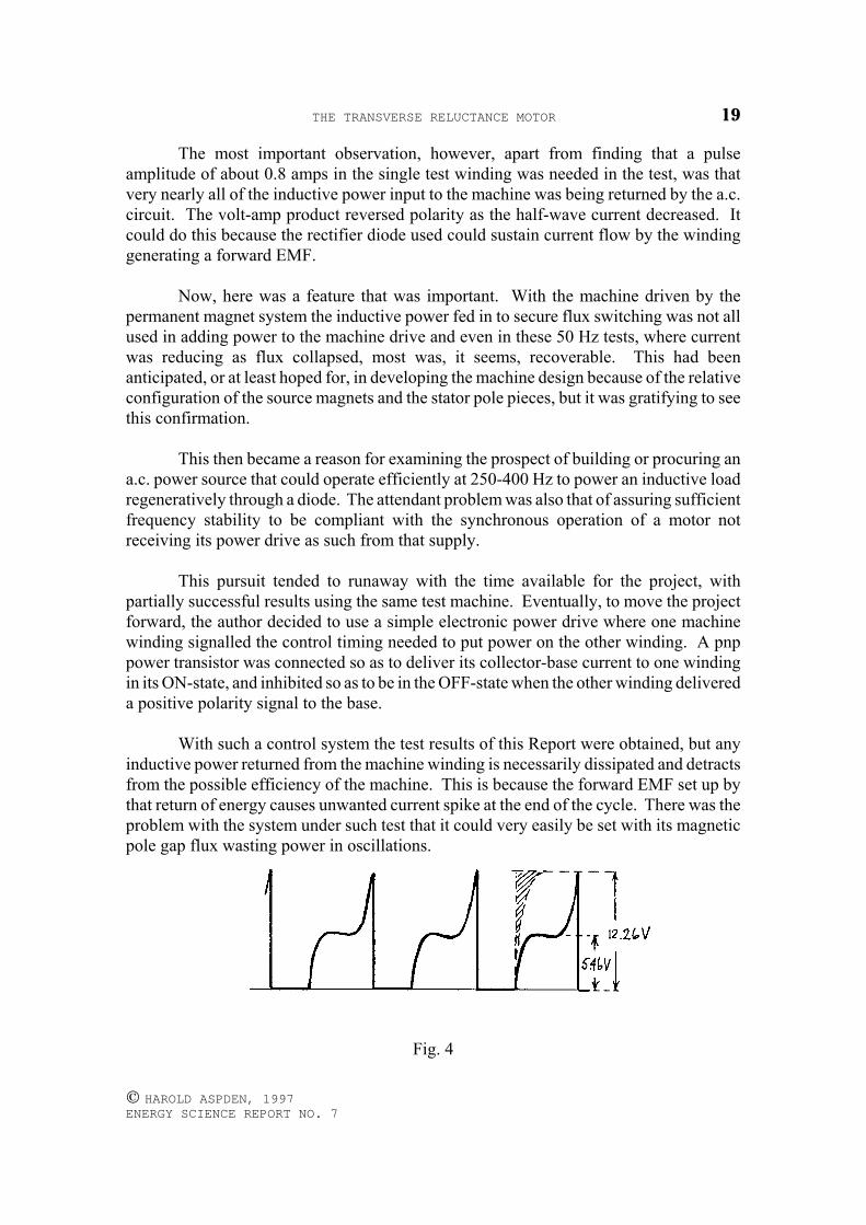
With such a control system the test results of this Report were obtained, but anyinductive power returned from the machine winding is necessarily dissipated and detractsfrom the possible efficiency of the machine. This is because the forward EMF set up bythat return of energy causes unwanted current spike at the end of the cycle. There was theproblem with the system under such test that it could very easily be set with its magneticpole gap flux wasting power in oscillations.
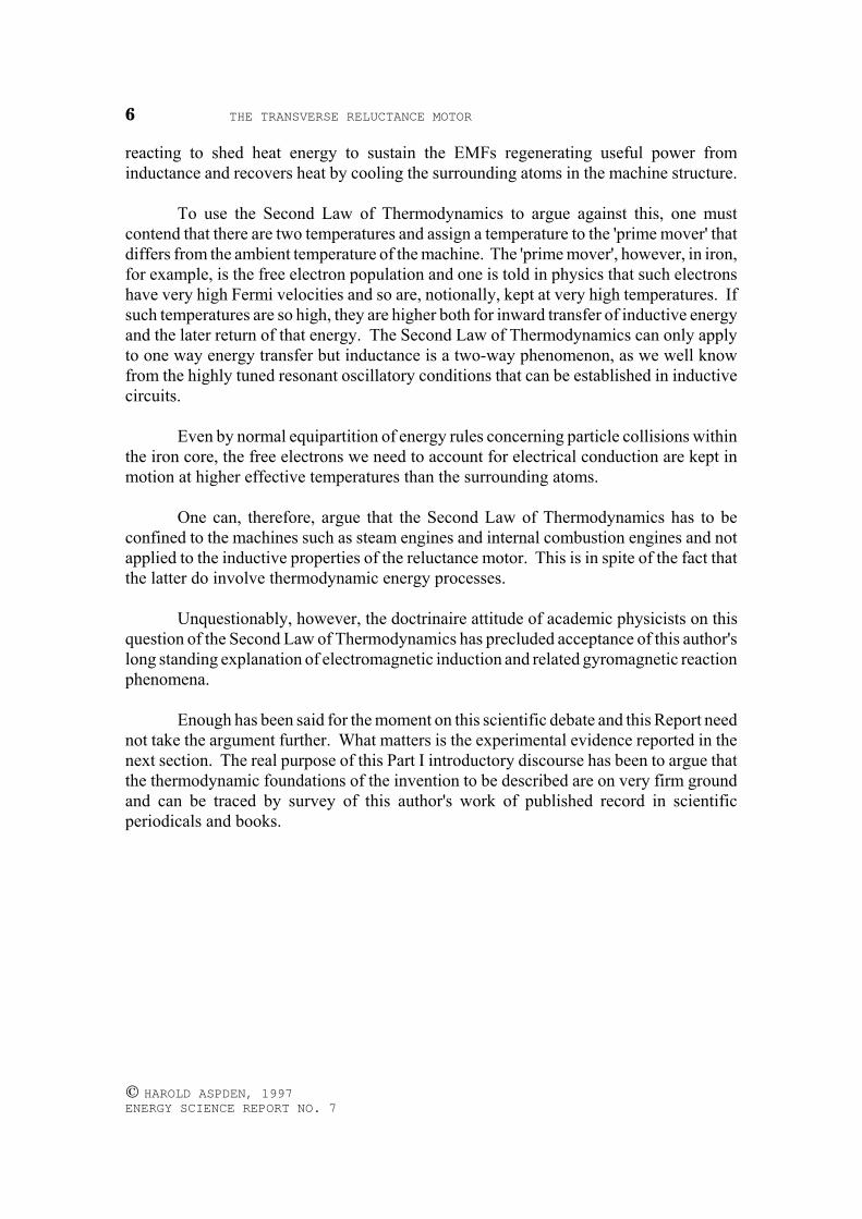
Fig. 4
THE TRANSVERSE RELUCTANCE MOTOR20
© HAROLD ASPDEN, 1997 ENERGY SCIENCE REPORT NO. 7
Had a capacitor been incorporated without informed design based on testperformance then that too could have aided oscillation, rather than helping to suppresssuch effects whilst storing energy for use in the next machine cycle.
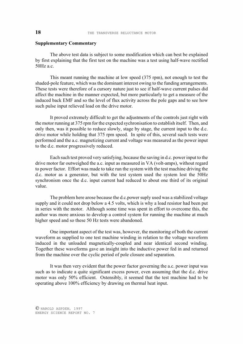
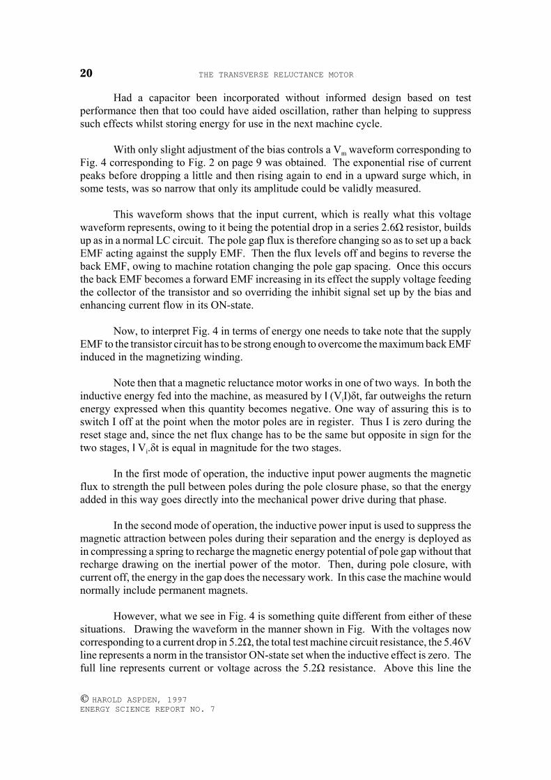
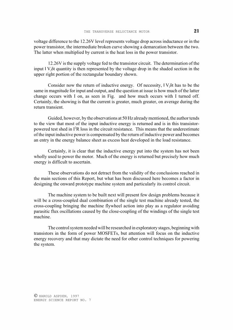
With only slight adjustment of the bias controls a Vm waveform corresponding toFig. 4 corresponding to Fig. 2 on page 9 was obtained. The exponential rise of currentpeaks before dropping a little and then rising again to end in a upward surge which, insome tests, was so narrow that only its amplitude could be validly measured.
This waveform shows that the input current, which is really what this voltagewaveform represents, owing to it being the potential drop in a series 2.6Ω resistor, buildsup as in a normal LC circuit. The pole gap flux is therefore changing so as to set up a backEMF acting against the supply EMF. Then the flux levels off and begins to reverse theback EMF, owing to machine rotation changing the pole gap spacing. Once this occursthe back EMF becomes a forward EMF increasing in its effect the supply voltage feedingthe collector of the transistor and so overriding the inhibit signal set up by the bias andenhancing current flow in its ON-state.
Now, to interpret Fig. 4 in terms of energy one needs to take note that the supplyEMF to the transistor circuit has to be strong enough to overcome the maximum back EMFinduced in the magnetizing winding.
Note then that a magnetic reluctance motor works in one of two ways. In both theinductive energy fed into the machine, as measured by I(ViI)δt, far outweighs the returnenergy expressed when this quantity becomes negative. One way of assuring this is toswitch I off at the point when the motor poles are in register. Thus I is zero during thereset stage and, since the net flux change has to be the same but opposite in sign for thetwo stages, IVi.δt is equal in magnitude for the two stages.
In the first mode of operation, the inductive input power augments the magneticflux to strength the pull between poles during the pole closure phase, so that the energyadded in this way goes directly into the mechanical power drive during that phase.
In the second mode of operation, the inductive power input is used to suppress themagnetic attraction between poles during their separation and the energy is deployed asin compressing a spring to recharge the magnetic energy potential of pole gap without thatrecharge drawing on the inertial power of the motor. Then, during pole closure, withcurrent off, the energy in the gap does the necessary work. In this case the machine wouldnormally include permanent magnets.
However, what we see in Fig. 4 is something quite different from either of thesesituations. Drawing the waveform in the manner shown in Fig. With the voltages nowcorresponding to a current drop in 5.2Ω, the total test machine circuit resistance, the 5.46Vline represents a norm in the transistor ON-state set when the inductive effect is zero. Thefull line represents current or voltage across the 5.2Ω resistance. Above this line the
THE TRANSVERSE RELUCTANCE MOTOR 21
© HAROLD ASPDEN, 1997 ENERGY SCIENCE REPORT NO. 7
voltage difference to the 12.26V level represents voltage drop across inductance or in thepower transistor, the intermediate broken curve showing a demarcation between the two.The latter when multiplied by current is the heat loss in the power transistor.
12.26V is the supply voltage fed to the transistor circuit. The determination of theinput IViδt quantity is then represented by the voltage drop in the shaded section in theupper right portion of the rectangular boundary shown.
Consider now the return of inductive energy. Of necessity, IViδt has to be thesame in magnitude for input and output, and the question at issue is how much of the latterchange occurs with I on, as seen in Fig. and how much occurs with I turned off.Certainly, the showing is that the current is greater, much greater, on average during thereturn transient.
Guided, however, by the observations at 50 Hz already mentioned, the author tendsto the view that most of the input inductive energy is returned and is in this transistor-powered test shed in I2R loss in the circuit resistance. This means that the underestimateof the input inductive power is compensated by the return of inductive power and becomesan entry in the energy balance sheet as excess heat developed in the load resistance.
Certainly, it is clear that the inductive energy put into the system has not beenwholly used to power the motor. Much of the energy is returned but precisely how muchenergy is difficult to ascertain.
These observations do not detract from the validity of the conclusions reached inthe main sections of this Report, but what has been discussed here becomes a factor indesigning the onward prototype machine system and particularly its control circuit.
The machine system to be built next will present few design problems because itwill be a cross-coupled dual combination of the single test machine already tested, thecross-coupling bringing the machine flywheel action into play as a regulator avoidingparasitic flux oscillations caused by the close-coupling of the windings of the single testmachine.
The control system needed will be researched in exploratory stages, beginning withtransistors in the form of power MOSFETs, but attention will focus on the inductiveenergy recovery and that may dictate the need for other control techniques for poweringthe system.
THE TRANSVERSE RELUCTANCE MOTOR22
© HAROLD ASPDEN, 1997 ENERGY SCIENCE REPORT NO. 7
APPENDIX I
LC Circuit Loss Analysis
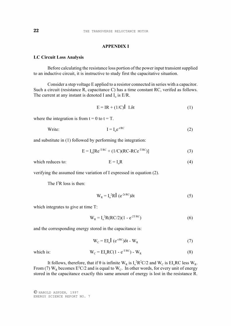
Before calculating the resistance loss portion of the power input transient suppliedto an inductive circuit, it is instructive to study first the capacitative situation.
Consider a step voltage E applied to a resistor connected in series with a capacitor.Such a circuit (resistance R, capacitance C) has a time constant RC, verifed as follows.The current at any instant is denoted I and Io is E/R.
E = IR + (1/C)I I.δt (1)
where the integration is from t = 0 to t = T.
Write: I = Ioe-t/RC (2)
and substitute in (1) followed by performing the integration:
E = Io[Re-T/RC + (1/C)(RC-RCe-T/RC)] (3)
which reduces to: E = IoR (4)
verifying the assumed time variation of I expressed in equation (2).
The I2R loss is then:
WR = Io2RI(e-2t/RC)δt (5)
which integrates to give at time T:
WR = Io2R(RC/2)(1 - e-2T/RC) (6)
and the corresponding energy stored in the capacitance is:
WC = EIoI(e-t/RC)δt - WR (7)
which is: WC = EIoRC(1 - e-T/RC) - WR (8)
It follows, therefore, that if θ is infinite WR is Io2R2C/2 and WC is EIoRC less WR.
From (7) WR becomes E2C/2 and is equal to WC. In other words, for every unit of energystored in the capacitance exactly this same amount of energy is lost in the resistance R.
THE TRANSVERSE RELUCTANCE MOTOR 23
© HAROLD ASPDEN, 1997 ENERGY SCIENCE REPORT NO. 7
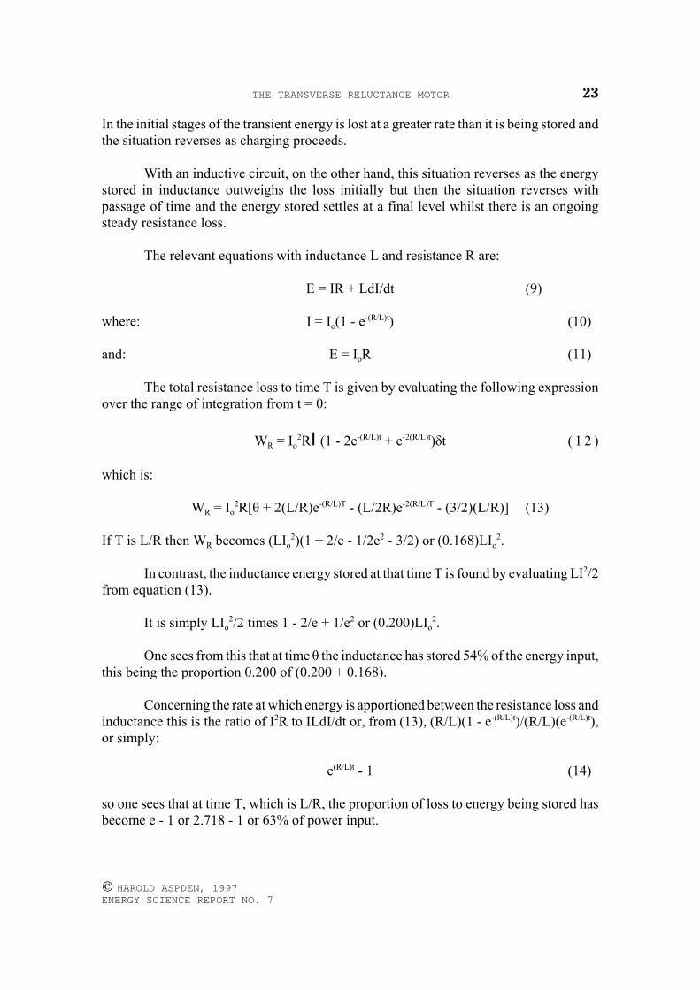
In the initial stages of the transient energy is lost at a greater rate than it is being stored andthe situation reverses as charging proceeds.
With an inductive circuit, on the other hand, this situation reverses as the energystored in inductance outweighs the loss initially but then the situation reverses withpassage of time and the energy stored settles at a final level whilst there is an ongoingsteady resistance loss.
The relevant equations with inductance L and resistance R are:
E = IR + LdI/dt (9)
where: I = Io(1 - e-(R/L)t) (10)
and: E = IoR (11)
The total resistance loss to time T is given by evaluating the following expressionover the range of integration from t = 0:
WR = Io2RI(1 - 2e-(R/L)t + e-2(R/L)t)δt ( 1 2 )
which is:
WR = Io2R[θ + 2(L/R)e-(R/L)T - (L/2R)e-2(R/L)T - (3/2)(L/R)] (13)
If T is L/R then WR becomes (LIo2)(1 + 2/e - 1/2e2 - 3/2) or (0.168)LIo
2.
In contrast, the inductance energy stored at that time T is found by evaluating LI2/2from equation (13).
It is simply LIo2/2 times 1 - 2/e + 1/e2 or (0.200)LIo
2.
One sees from this that at time θ the inductance has stored 54% of the energy input,this being the proportion 0.200 of (0.200 + 0.168).
Concerning the rate at which energy is apportioned between the resistance loss andinductance this is the ratio of I2R to ILdI/dt or, from (13), (R/L)(1 - e-(R/L)t)/(R/L)(e-(R/L)t),or simply:
e(R/L)t - 1 (14)
so one sees that at time T, which is L/R, the proportion of loss to energy being stored hasbecome e - 1 or 2.718 - 1 or 63% of power input.
THE TRANSVERSE RELUCTANCE MOTOR24
© HAROLD ASPDEN, 1997 ENERGY SCIENCE REPORT NO. 7
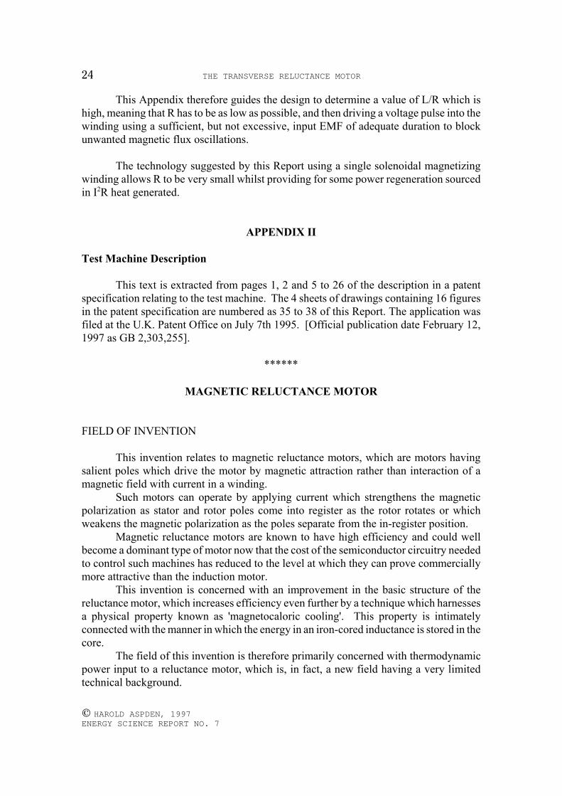
This Appendix therefore guides the design to determine a value of L/R which ishigh, meaning that R has to be as low as possible, and then driving a voltage pulse into thewinding using a sufficient, but not excessive, input EMF of adequate duration to blockunwanted magnetic flux oscillations.
The technology suggested by this Report using a single solenoidal magnetizingwinding allows R to be very small whilst providing for some power regeneration sourcedin I2R heat generated.
APPENDIX II
Test Machine Description
This text is extracted from pages 1, 2 and 5 to 26 of the description in a patentspecification relating to the test machine. The 4 sheets of drawings containing 16 figuresin the patent specification are numbered as 35 to 38 of this Report. The application wasfiled at the U.K. Patent Office on July 7th 1995. [Official publication date February 12,1997 as GB 2,303,255].
******
MAGNETIC RELUCTANCE MOTOR
FIELD OF INVENTION
This invention relates to magnetic reluctance motors, which are motors havingsalient poles which drive the motor by magnetic attraction rather than interaction of amagnetic field with current in a winding.
Such motors can operate by applying current which strengthens the magneticpolarization as stator and rotor poles come into register as the rotor rotates or whichweakens the magnetic polarization as the poles separate from the in-register position.
Magnetic reluctance motors are known to have high efficiency and could wellbecome a dominant type of motor now that the cost of the semiconductor circuitry neededto control such machines has reduced to the level at which they can prove commerciallymore attractive than the induction motor.
This invention is concerned with an improvement in the basic structure of thereluctance motor, which increases efficiency even further by a technique which harnessesa physical property known as 'magnetocaloric cooling'. This property is intimatelyconnected with the manner in which the energy in an iron-cored inductance is stored in thecore.
The field of this invention is therefore primarily concerned with thermodynamicpower input to a reluctance motor, which is, in fact, a new field having a very limitedtechnical background.
THE TRANSVERSE RELUCTANCE MOTOR 25
© HAROLD ASPDEN, 1997 ENERGY SCIENCE REPORT NO. 7
BACKGROUND OF INVENTION
The background relevant to this invention, so far as it is known to the Applicant,will be described in the following specification, by reference to the drawings. At this stageit suffices to make simple bibliographical reference to the following patents which arediscussed in this specification. These are:
GB Patent No. 2,234,863 corresponding to U.S. Patent No. 4,975,608, GB PatentApplication No. 2,267,995 corresponding to U.S. Patent No. 5,376,184, and GB PatentApplication No. 2,282,708, the first four of these having the same applicant as applies tothe subject invention and the latter having additionally, as co-applicant, Robert GeorgeAdams of New Zealand. GB Patent No. 547,668 granted to Stanley Isaiah Hitchcock.
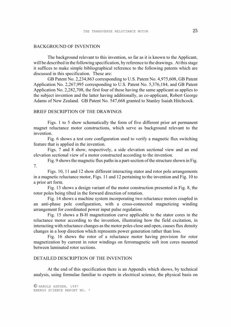
BRIEF DESCRIPTION OF THE DRAWINGS
Figs. 1 to 5 show schematically the form of five different prior art permanentmagnet reluctance motor constructions, which serve as background relevant to theinvention.
Fig. 6 shows a test core configuration used to verify a magnetic flux switchingfeature that is applied in the invention.
Figs. 7 and 8 show, respectively, a side elevation sectional view and an endelevation sectional view of a motor constructed according to the invention.
Fig. 9 shows the magnetic flux paths in a part-section of the structure shown in Fig.7.
Figs. 10, 11 and 12 show different interacting stator and rotor pole arrangementsin a magnetic reluctance motor, Figs. 11 and 12 pertaining to the invention and Fig. 10 toa prior art form.
Fig. 13 shows a design variant of the motor construction presented in Fig. 8, therotor poles being tilted in the forward direction of rotation.
Fig. 14 shows a machine system incorporating two reluctance motors coupled inan anti-phase pole configuration, with a cross-connected magnetizing windingarrangement for coordinated power input pulse regulation.
Fig. 15 shows a B-H magnetization curve applicable to the stator cores in thereluctance motor according to the invention, illustrating how the field excitation, ininteracting with reluctance changes as the motor poles close and open, causes flux densitychanges in a loop direction which represents power generation rather than loss.
Fig. 16 shows the rotor of a reluctance motor having provision for rotormagnetization by current in rotor windings on ferromagnetic soft iron cores mountedbetween laminated rotor sections.
DETAILED DESCRIPTION OF THE INVENTION
At the end of this specification there is an Appendix which shows, by technicalanalysis, using formulae familiar to experts in electrical science, the physical basis on
THE TRANSVERSE RELUCTANCE MOTOR26
© HAROLD ASPDEN, 1997 ENERGY SCIENCE REPORT NO. 7
which this invention relies. What is described and claimed has been established byexperiment, but inasmuch as it will surprise many experts in the art to learn thatthermodynamic effects can contribute to the improved efficiency of an electric motor, theApplicant has deemed it prudent to give the formal scientific basis for the research whichunderlies this invention.
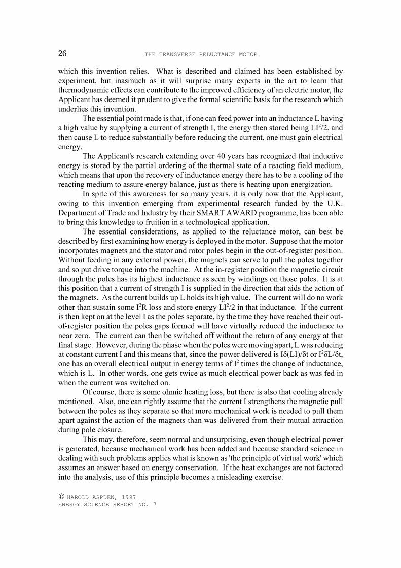
The essential point made is that, if one can feed power into an inductance L havinga high value by supplying a current of strength I, the energy then stored being LI2/2, andthen cause L to reduce substantially before reducing the current, one must gain electricalenergy.
The Applicant's research extending over 40 years has recognized that inductiveenergy is stored by the partial ordering of the thermal state of a reacting field medium,which means that upon the recovery of inductance energy there has to be a cooling of thereacting medium to assure energy balance, just as there is heating upon energization.
In spite of this awareness for so many years, it is only now that the Applicant,owing to this invention emerging from experimental research funded by the U.K.Department of Trade and Industry by their SMART AWARD programme, has been ableto bring this knowledge to fruition in a technological application.
The essential considerations, as applied to the reluctance motor, can best bedescribed by first examining how energy is deployed in the motor. Suppose that the motorincorporates magnets and the stator and rotor poles begin in the out-of-register position.Without feeding in any external power, the magnets can serve to pull the poles togetherand so put drive torque into the machine. At the in-register position the magnetic circuitthrough the poles has its highest inductance as seen by windings on those poles. It is atthis position that a current of strength I is supplied in the direction that aids the action ofthe magnets. As the current builds up L holds its high value. The current will do no workother than sustain some I2R loss and store energy LI2/2 in that inductance. If the currentis then kept on at the level I as the poles separate, by the time they have reached their out-of-register position the poles gaps formed will have virtually reduced the inductance tonear zero. The current can then be switched off without the return of any energy at thatfinal stage. However, during the phase when the poles were moving apart, L was reducingat constant current I and this means that, since the power delivered is Iδ(LI)/δt or I2δL/δt,one has an overall electrical output in energy terms of I2 times the change of inductance,which is L. In other words, one gets twice as much electrical power back as was fed inwhen the current was switched on.
Of course, there is some ohmic heating loss, but there is also that cooling alreadymentioned. Also, one can rightly assume that the current I strengthens the magnetic pullbetween the poles as they separate so that more mechanical work is needed to pull themapart against the action of the magnets than was delivered from their mutual attractionduring pole closure.
This may, therefore, seem normal and unsurprising, even though electrical poweris generated, because mechanical work has been added and because standard science indealing with such problems applies what is known as 'the principle of virtual work' whichassumes an answer based on energy conservation. If the heat exchanges are not factoredinto the analysis, use of this principle becomes a misleading exercise.
THE TRANSVERSE RELUCTANCE MOTOR 27
© HAROLD ASPDEN, 1997 ENERGY SCIENCE REPORT NO. 7
Now consider the situation where that same current I is applied in the oppositedirection to weaken the magnetic flux between the poles when they are fully in register.The current experiences a back EMF in the windings and only senses flux rate of change;it has no knowledge of the biasing magnetic field set up by the magnets. There will beinductance energy supplied as input amounting to LI2/2 as before. In this case the polescan separate without there being any strong magnetic attraction demanding mechanicalenergy, because the magnetic flux has been biased to a zero value. As the poles separatethe current can reduce progressively to keep the zero flux condition and no exchange ofinductive power occurs. The overall result is that the energy input LI2/2 has been spentand mechanical energy gained from the magnet during the pole closure phase. These twoenergies can be presumed to be equal, but if the motor has the design described below, itis found that the mechanical drive power of the machine exceeds the inductive powerinput. It is then a matter of design to reduce the I2R heating loss so as to gain overallenhancement of motor efficiency by the magnetocaloric cooling thus evidenced.
The reluctance motor which has variable pole gaps complicates the situationrepresented in the Appendix, the more so if magnets are involved, and it should beexplained that using the magnetizing current to divert flux from the magnet and along aleakage path will set up demagnetization effects which effectively reduce the inductanceL. This allows the value of the current I and the angular position of the rotor in adjustingthe pole gaps to combine as a control determining LI.
As one then sees from the Appendix, the root principle of the power gain argumentis that if one can contrive to reduce LI of a circuit whilst it carries constant current I, thenthe inductance will deliver more energy output than was supplied and there will becommensurate cooling in the inductor core. By suitable positioning of magnets ormagnetizing windings in a reluctance motor, this becomes feasible technologically.
The essential design factor in this is the positioning of the magnets or windingswhich govern the inductance at positions not directly linked by a magnetic field to the seatof the inductive action. Here 'magnetic field' is used in the context of ampere-turns andis distinct from the magnetic flux which necessarily provides the inductive linkage. Themagnets or windings can be placed in positions offset from the pole gaps in a reluctancemotor or positioned with axes orthogonally angled with respect to the flux direction in thepole gaps.
Referring to Figs. 1 to 6, the background applicable to this invention will now bedescribed.
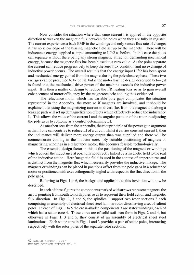
In each of these figures the components marked with arrows represent magnets, thearrow pointing from south to north poles so as to represent their field action and magneticflux direction. In Figs. 1, 3 and 5, the spindles 1 support two rotor sections 2 eachcomprising an assembly of electrical sheet steel laminar rotor discs having a set of salientpoles. In each of Figs. 1 to 5 the cross-shaded components 3 are stator windings, each ofwhich has a stator core 4. These cores are of solid soft-iron form in Figs. 2 and 4, butotherwise in Figs. 1, 3 and 5, they consist of an assembly of electrical sheet steellaminations. Each stator core in Figs. 1 and 3 provides a pair of stator poles, interactingrespectively with the rotor poles of the separate rotor sections.
THE TRANSVERSE RELUCTANCE MOTOR28
© HAROLD ASPDEN, 1997 ENERGY SCIENCE REPORT NO. 7
Fig. 1 shows a prior art reluctance motor disclosed by this Applicant in GB PatentNo. 2,234,863, corresponding to US Patent No. 4,975,608. In principle the motor theredisclosed has magnetizing windings 3 which, when energized, block the through-passageof magnetic flux sourced in the magnets, forcing diversion around a path through outerbridging yokes 5 to the poles on stators 3 and corresponding poles of the two rotor sections2. These rotor sections serve, according to the angular position of the spindle 1, to openor close pole gaps between the rotor and stator so that flux from one pair of magnets in onestator core can return as flux through another pair of magnets on an adjacent stator core.There is an even number of such stator cores and the magnets of adjacent stator cores arearranged with opposite polarization directions to assure this.
By pulsing current through the windings 3 at times when the poles are closing, thisallows the magnets to drive the motor. As the poles separate the current is switched offand the magnetic flux diverts through the stator 4, the path of least reluctance, leaving thepoles free to separate.
The relevance of this prior art disclosure is its showing of magnetizing windingsthat are mounted parallel with the spindle axis and so are orthogonal with respect to theflux direction across the pole gap.
In the invention, the subject of this patent application, a superior constructionincorporating the magnets in the body of the rotor is disclosed. It has been found easierto exclude from the pole gaps the flux sourced in the magnets if the latter are rotor-mounted, as opposed to stator mounted.
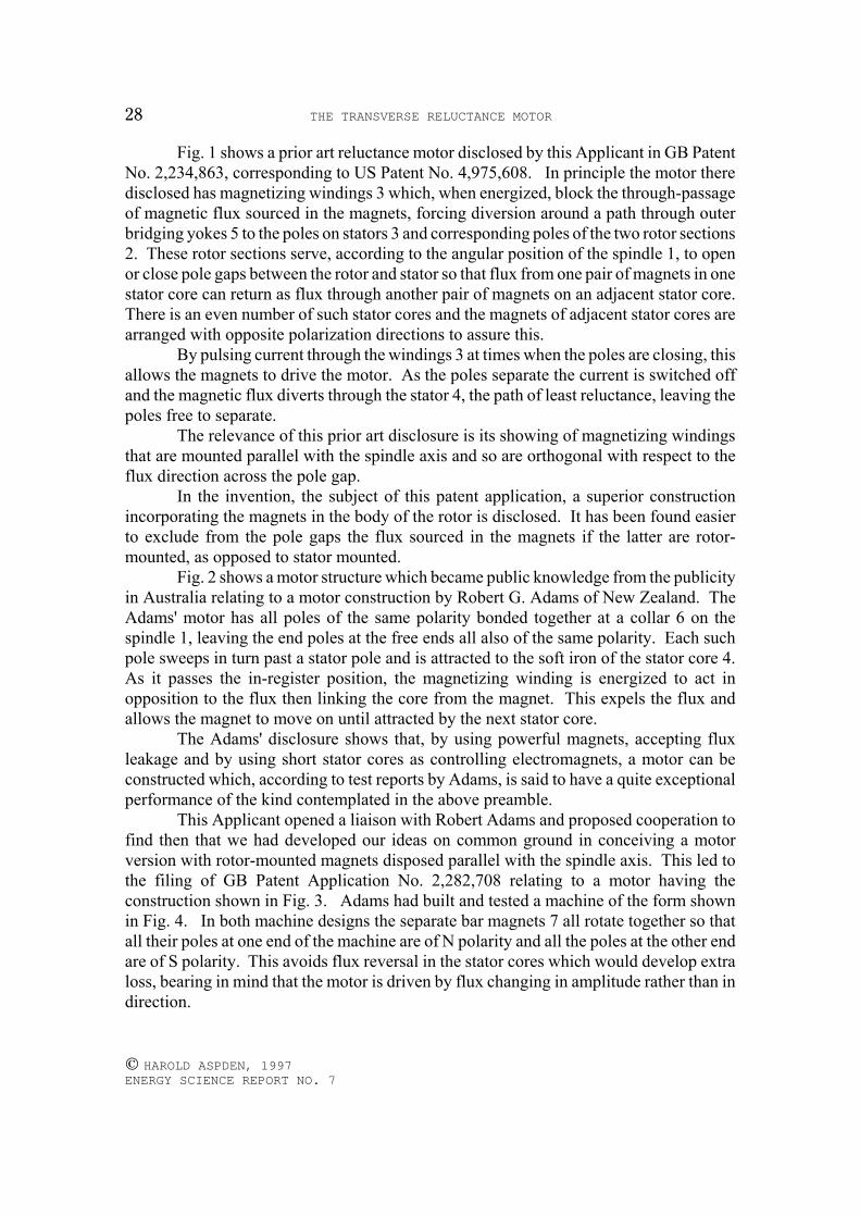
Fig. 2 shows a motor structure which became public knowledge from the publicityin Australia relating to a motor construction by Robert G. Adams of New Zealand. TheAdams' motor has all poles of the same polarity bonded together at a collar 6 on thespindle 1, leaving the end poles at the free ends all also of the same polarity. Each suchpole sweeps in turn past a stator pole and is attracted to the soft iron of the stator core 4.As it passes the in-register position, the magnetizing winding is energized to act inopposition to the flux then linking the core from the magnet. This expels the flux andallows the magnet to move on until attracted by the next stator core.
The Adams' disclosure shows that, by using powerful magnets, accepting fluxleakage and by using short stator cores as controlling electromagnets, a motor can beconstructed which, according to test reports by Adams, is said to have a quite exceptionalperformance of the kind contemplated in the above preamble.
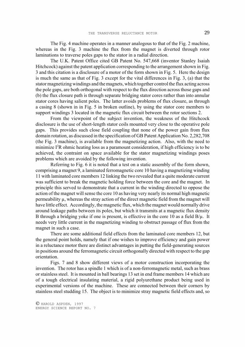
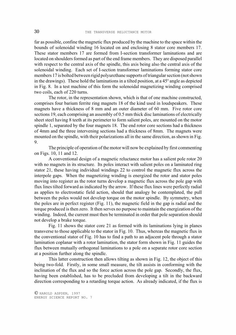
This Applicant opened a liaison with Robert Adams and proposed cooperation tofind then that we had developed our ideas on common ground in conceiving a motorversion with rotor-mounted magnets disposed parallel with the spindle axis. This led tothe filing of GB Patent Application No. 2,282,708 relating to a motor having theconstruction shown in Fig. 3. Adams had built and tested a machine of the form shownin Fig. 4. In both machine designs the separate bar magnets 7 all rotate together so thatall their poles at one end of the machine are of N polarity and all the poles at the other endare of S polarity. This avoids flux reversal in the stator cores which would develop extraloss, bearing in mind that the motor is driven by flux changing in amplitude rather than indirection.
THE TRANSVERSE RELUCTANCE MOTOR 29
© HAROLD ASPDEN, 1997 ENERGY SCIENCE REPORT NO. 7
The Fig. 4 machine operates in a manner analogous to that of the Fig. 2 machine,whereas in the Fig. 3 machine the flux from the magnet is diverted through rotorlaminations to traverse poles gaps to the stator in a radial direction.
The U.K. Patent Office cited GB Patent No. 547,668 (inventor Stanley IsaiahHitchcock) against the patent application corresponding to the arrangement shown in Fig.3 and this citation is a disclosure of a motor of the form shown in Fig. 5. Here the designis much the same as that of Fig. 3 except for the vital differences in Fig. 3, (a) that thestator magnetizing windings and the magnets, which together control the flux acting acrossthe pole gaps, are both orthogonal with respect to the flux direction across those gaps and(b) the flux closure path is through separate bridging stator cores rather than into annularstator cores having salient poles. The latter avoids problems of flux closure, as througha casing 8 (shown in in Fig. 5 in broken outline), by using the stator core members tosupport windings 3 located in the magnetic flux circuit between the rotor sections 2.
From the viewpoint of the subject invention, the weakness of the Hitchcockdisclosure is the use of short-length stator coils mounted very close to the operative polegaps. This provides such close field coupling that none of the power gain from fluxdomain rotation, as discussed in the specification of GB Patent Application No. 2,282,708(the Fig. 3 machine), is available from the magnetizing action. Also, with the need tominimize I2R ohmic heating loss as a paramount consideration, if high efficiency is to beachieved, the contraint on space available for the stator magnetizing windings posesproblems which are avoided by the following invention.
Referring to Fig. 6 it is noted that a test on a static assembly of the form shown,comprising a magnet 9, a laminated ferromagnetic core 10 having a magnetizing winding11 with laminated core members 12 linking the two revealed that a quite moderate currentwas sufficient to break the magnetic holding force between the core and the magnet. Inprinciple this served to demonstrate that a current in the winding directed to oppose theaction of the magnet will sense the core 10 as having very nearly its normal high magneticpermeability µ, whereas the stray action of the direct magnetic field from the magnet willhave little effect. Accordingly, the magnetic flux, which the magnet would normally drivearound leakage paths between its poles, but which it transmits at a magnetic flux densityB through a bridging yoke if one is present, is effective in the core 10 as a field B/µ. Itneeds very little current in the magnetizing winding to obstruct passage of flux from themagnet in such a case.
There are some additional field effects from the laminated core members 12, butthe general point holds, namely that if one wishes to improve efficiency and gain powerin a reluctance motor there are distinct advantages in putting the field-generating sourcesin positions around the ferromagnetic circuit orthogonally directed with respect to the gaporientation.
Figs. 7 and 8 show different views of a motor construction incorporating theinvention. The rotor has a spindle 1 which is of a non-ferromagnetic metal, such as brassor stainless steel. It is mounted in ball bearings 13 set in end frame members 14 which areof a tough electrical insulating material, a rigid polyurethane product being used inexperimental versions of the machine. These are connected between their corners bystainless steel studding 15. The object is to minimize stray magnetic field effects and, so
THE TRANSVERSE RELUCTANCE MOTOR30
© HAROLD ASPDEN, 1997 ENERGY SCIENCE REPORT NO. 7
far as possible, confine the magnetic flux produced by the machine to the space within thebounds of solenoidal winding 16 located on and enclosing 8 stator core members 17.These stator members 17 are formed from I-section transformer laminations and arelocated on shoulders formed as part of the end frame members. They are disposed parallelwith respect to the central axis of the spindle, this axis being also the central axis of thesolenoidal winding. Each set of I-section transformer laminations forming stator coremembers 17 is bolted between rigid polyurethane supports of triangular section (not shownin the drawings). These hold the laminations in a tilted position, at a 45o angle as depictedin Fig. 8. In a test machine of this form the solenoidal magnetizing winding comprisedtwo coils, each of 220 turns.
The rotor, in the representation shown, which is that of one machine constructed,comprises four barium ferrite ring magnets 18 of the kind used in loudspeakers. Thesemagnets have a thickness of 8 mm and an outer diameter of 60 mm. Five rotor coresections 19, each comprising an assembly of 0.5 mm thick disc laminations of electricallysheet steel having 8 teeth at its perimeter to form salient poles, are mounted on the motorspindle 1, separated by the four magnets 18. The end rotor core sections had a thicknessof 4mm and the three intervening sections had a thickness of 8mm. The magnets weremounted on the spindle, with their polarizations all in the same direction, as shown in Fig.9.
The principle of operation of the motor will now be explained by first commentingon Figs. 10, 11 and 12.
A conventional design of a magnetic reluctance motor has a salient pole rotor 20with no magnets in its structure. Its poles interact with salient poles on a laminated ringstator 21, these having individual windings 22 to control the magnetic flux across theinterpole gaps. When the magnetizing winding is energized the rotor and stator polesmoving into register as the rotor turns develop a magnetic flux across the pole gap withflux lines tilted forward as indicated by the arrow. If these flux lines were perfectly radialas applies to electrostatic field action, should that analogy be contemplated, the pullbetween the poles would not develop torque on the motor spindle. By symmetry, whenthe poles are in perfect register (Fig. 11), the magnetic field in the gap is radial and thetorque produced is then zero. It then serves no purpose to maintain the energization of thewinding. Indeed, the current must then be terminated in order that pole separation shouldnot develop a brake torque.
Fig. 11 shows the stator core 21 as formed with its laminations lying in planestransverse to those applicable to the stator in Fig. 10. Thus, whereas the magnetic flux inthe conventional stator of Fig. 10 has to find a path to an adjacent pole through a statorlamination coplanar with a rotor lamination, the stator form shown in Fig. 11 guides theflux between mutually orthogonal laminations to a pole on a separate rotor core sectionat a position further along the spindle.
This latter construction then allows tilting as shown in Fig. 12, the object of thisbeing two-fold. Firstly, in some small measure, the tilt assists in conforming with theinclination of the flux and so the force action across the pole gap. Secondly, the flux,having been established, has to be precluded from developing a tilt in the backwarddirection corresponding to a retarding torque action. As already indicated, if the flux is
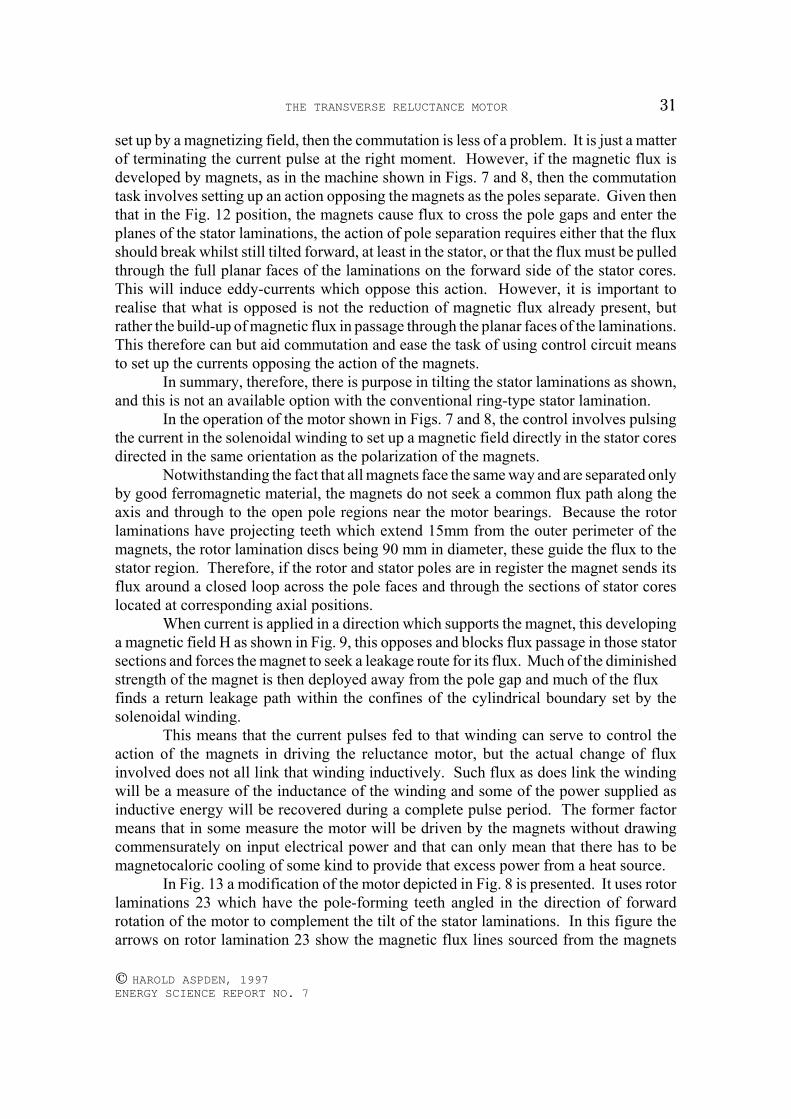
THE TRANSVERSE RELUCTANCE MOTOR 31
© HAROLD ASPDEN, 1997 ENERGY SCIENCE REPORT NO. 7
set up by a magnetizing field, then the commutation is less of a problem. It is just a matterof terminating the current pulse at the right moment. However, if the magnetic flux isdeveloped by magnets, as in the machine shown in Figs. 7 and 8, then the commutationtask involves setting up an action opposing the magnets as the poles separate. Given thenthat in the Fig. 12 position, the magnets cause flux to cross the pole gaps and enter theplanes of the stator laminations, the action of pole separation requires either that the fluxshould break whilst still tilted forward, at least in the stator, or that the flux must be pulledthrough the full planar faces of the laminations on the forward side of the stator cores.This will induce eddy-currents which oppose this action. However, it is important torealise that what is opposed is not the reduction of magnetic flux already present, butrather the build-up of magnetic flux in passage through the planar faces of the laminations.This therefore can but aid commutation and ease the task of using control circuit meansto set up the currents opposing the action of the magnets.
In summary, therefore, there is purpose in tilting the stator laminations as shown,and this is not an available option with the conventional ring-type stator lamination.
In the operation of the motor shown in Figs. 7 and 8, the control involves pulsingthe current in the solenoidal winding to set up a magnetic field directly in the stator coresdirected in the same orientation as the polarization of the magnets.
Notwithstanding the fact that all magnets face the same way and are separated onlyby good ferromagnetic material, the magnets do not seek a common flux path along theaxis and through to the open pole regions near the motor bearings. Because the rotorlaminations have projecting teeth which extend 15mm from the outer perimeter of themagnets, the rotor lamination discs being 90 mm in diameter, these guide the flux to thestator region. Therefore, if the rotor and stator poles are in register the magnet sends itsflux around a closed loop across the pole faces and through the sections of stator coreslocated at corresponding axial positions.
When current is applied in a direction which supports the magnet, this developinga magnetic field H as shown in Fig. 9, this opposes and blocks flux passage in those statorsections and forces the magnet to seek a leakage route for its flux. Much of the diminishedstrength of the magnet is then deployed away from the pole gap and much of the flux finds a return leakage path within the confines of the cylindrical boundary set by thesolenoidal winding.
This means that the current pulses fed to that winding can serve to control theaction of the magnets in driving the reluctance motor, but the actual change of fluxinvolved does not all link that winding inductively. Such flux as does link the windingwill be a measure of the inductance of the winding and some of the power supplied asinductive energy will be recovered during a complete pulse period. The former factormeans that in some measure the motor will be driven by the magnets without drawingcommensurately on input electrical power and that can only mean that there has to bemagnetocaloric cooling of some kind to provide that excess power from a heat source.
In Fig. 13 a modification of the motor depicted in Fig. 8 is presented. It uses rotorlaminations 23 which have the pole-forming teeth angled in the direction of forwardrotation of the motor to complement the tilt of the stator laminations. In this figure thearrows on rotor lamination 23 show the magnetic flux lines sourced from the magnets
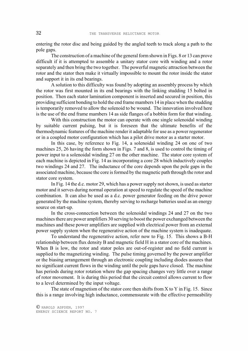
THE TRANSVERSE RELUCTANCE MOTOR32
© HAROLD ASPDEN, 1997 ENERGY SCIENCE REPORT NO. 7
entering the rotor disc and being guided by the angled teeth to track along a path to thepole gaps.
The construction of a machine of the general form shown in Figs. 8 or 13 can provedifficult if it is attempted to assemble a unitary stator core with winding and a rotorseparately and then bring the two together. The powerful magnetic attraction between therotor and the stator then make it virtually impossible to mount the rotor inside the statorand support it in its end bearings.
A solution to this difficulty was found by adopting an assembly process by whichthe rotor was first mounted in its end bearings with the linking studding 15 bolted inposition. Then each stator lamination component is inserted and secured in position, thisproviding sufficient bonding to hold the end frame mambers 14 in place when the studdingis temporarily removed to allow the solenoid to be wound. The innovation involved hereis the use of the end frame mambers 14 as side flanges of a bobbin form for that winding.
With this construction the motor can operate with one single solenoidal windingby suitable current pulsing, but it is foreseen that the ultimate benefits of thethermodynamic features of the machine render it adaptable for use as a power regeneratoror in a coupled motor configuration which has a pilot drive motor as a starter motor.
In this case, by reference to Fig. 14, a solenoidal winding 24 on one of twomachines 25, 26 having the form shown in Figs. 7 and 8, is used to control the timing ofpower input to a solenoidal winding 27 on the other machine. The stator core system ofeach machine is depicted in Fig. 14 as incorporating a core 28 which inductively couplestwo windings 24 and 27. The inductance of the core depends upon the pole gaps in theassociated machine, because the core is formed by the magnetic path through the rotor andstator core system.
In Fig. 14 the d.c. motor 29, which has a power supply not shown, is used as startermotor and it serves during normal operation at speed to regulate the speed of the machinecombination. It can also be used as a d.c. power generator feeding on the drive powergenerated by the machine system, thereby serving to recharge batteries used as an energysource on start-up.
In the cross-connection between the solenoidal windings 24 and 27 on the twomachines there are power amplifiers 30 serving to boost the power exchanged between themachines and these power amplifiers are supplied with electrical power from an externalpower supply system when the regenerative action of the machine system is inadequate.
To understand the regenerative action, refer now to Fig. 15. This shows a B-Hrelationship between flux density B and magnetic field H in a stator core of the machines.When B is low, the rotor and stator poles are out-of-register and no field current issupplied to the magnetizing winding. The pulse timing governed by the power amplifieror the biasing arrangement through an electronic coupling including diodes assures thatno significant current flows in the winding until the pole gaps have closed. The machinehas periods during rotor rotation where the gap spacing changes very little over a rangeof rotor movement. It is during this period that the circuit control allows current to flowto a level determined by the input voltage.
The state of magnetism of the stator core then shifts from X to Y in Fig. 15. Sincethis is a range involving high inductance, commensurate with the effective permeability
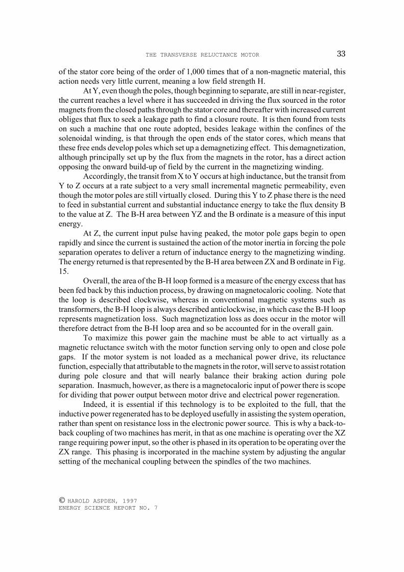
THE TRANSVERSE RELUCTANCE MOTOR 33
© HAROLD ASPDEN, 1997 ENERGY SCIENCE REPORT NO. 7
of the stator core being of the order of 1,000 times that of a non-magnetic material, thisaction needs very little current, meaning a low field strength H.
At Y, even though the poles, though beginning to separate, are still in near-register,the current reaches a level where it has succeeded in driving the flux sourced in the rotormagnets from the closed paths through the stator core and thereafter with increased currentobliges that flux to seek a leakage path to find a closure route. It is then found from testson such a machine that one route adopted, besides leakage within the confines of thesolenoidal winding, is that through the open ends of the stator cores, which means thatthese free ends develop poles which set up a demagnetizing effect. This demagnetization,although principally set up by the flux from the magnets in the rotor, has a direct actionopposing the onward build-up of field by the current in the magnetizing winding.
Accordingly, the transit from X to Y occurs at high inductance, but the transit fromY to Z occurs at a rate subject to a very small incremental magnetic permeability, eventhough the motor poles are still virtually closed. During this Y to Z phase there is the needto feed in substantial current and substantial inductance energy to take the flux density Bto the value at Z. The B-H area between YZ and the B ordinate is a measure of this inputenergy.
At Z, the current input pulse having peaked, the motor pole gaps begin to openrapidly and since the current is sustained the action of the motor inertia in forcing the poleseparation operates to deliver a return of inductance energy to the magnetizing winding.The energy returned is that represented by the B-H area between ZX and B ordinate in Fig.15.
Overall, the area of the B-H loop formed is a measure of the energy excess that hasbeen fed back by this induction process, by drawing on magnetocaloric cooling. Note thatthe loop is described clockwise, whereas in conventional magnetic systems such astransformers, the B-H loop is always described anticlockwise, in which case the B-H looprepresents magnetization loss. Such magnetization loss as does occur in the motor willtherefore detract from the B-H loop area and so be accounted for in the overall gain.
To maximize this power gain the machine must be able to act virtually as amagnetic reluctance switch with the motor function serving only to open and close polegaps. If the motor system is not loaded as a mechanical power drive, its reluctancefunction, especially that attributable to the magnets in the rotor, will serve to assist rotationduring pole closure and that will nearly balance their braking action during poleseparation. Inasmuch, however, as there is a magnetocaloric input of power there is scopefor dividing that power output between motor drive and electrical power regeneration.
Indeed, it is essential if this technology is to be exploited to the full, that theinductive power regenerated has to be deployed usefully in assisting the system operation,rather than spent on resistance loss in the electronic power source. This is why a back-to-back coupling of two machines has merit, in that as one machine is operating over the XZrange requiring power input, so the other is phased in its operation to be operating over theZX range. This phasing is incorporated in the machine system by adjusting the angularsetting of the mechanical coupling between the spindles of the two machines.
THE TRANSVERSE RELUCTANCE MOTOR34
© HAROLD ASPDEN, 1997 ENERGY SCIENCE REPORT NO. 7
The induced EMFs in windings 24 are anti-phase signals so that by suitableelectronics, or simply diode interposition, they can be used to cross-feed power betweenthe machines when set with the appropriate pole position phasing.
A typical test on one machine system using the structure shown in Figs. 7 and 8 hasshown that more inductive energy is returned in each flux cycle than is supplied as input,even though the d.c. starter motor itself drew a reduced power whilst the whole systemincreased in speed from 800 rpm to 1350 rpm. In this case the inductive power gain,though positive, was marginal in comparison with the mechanical power gain, but thefindings were a very clear indication that the theoretical basis of this invention, with itsreliance on a magnetocaloric cooling as a source of excess electrical power input, issoundly based.
Although the invention has been described in its form as implemented in a testprototype, which used permanent magnets, it is to be understood that the essentialcomponent is the ferromagnetic core in the system, which need not be of permanentmagnet material.
In its technological application, the optimum design based on this inventiondepends upon the scale of the machine. A large machine system can employ rotor andstator structures which are simply electromagnetic in form, provided the core isferromagnetic. The key feature of the invention is the way in which the reluctance of thecore effective in the magnetizing winding can be switched from a high inductance stateto a low inductance state by means not directly coupled to that magnetizing winding. Thespecific design of the reluctance motor by which the pole closure and pole separationdesign serve this reluctance switching functions is the attribute which brings about theenhanced efficiency condition. The permanent magnets are not essential and, indeed, arotor built with a soft iron ring cores 31 to replace the magnets with rotor windings 32such as is shown in Fig. 16 could serve quite well functionally and in fact better in costterms in a large machine.
The rotor winding, supplied through slip rings, would merely carry a steady d.c.current and the flux changes resulting from the pole opening and closing would set upeddy-currents which involve a moderate loss. However, these currents would have limitedcore penetration and would tend to sustain a steady magnetic flux condition in the bodyof the rotor. As with the coercive force action of a permanent magnet, these would helpto force the leakage flux action that is part of the functional operation of the machine asdescribed.
The importance of the enveloping solenoidal winding as the primary magnetizingwinding governing motor operation can be seen when it is realized that, if individualwindings are used on each stator core, these would need to be segmented along the corelength so as not to obstruct the pole gaps. The enveloping solenoidal winding hastherefore several advantages, namely its low resistance because of its unrestricted outerdiameter, its ease of assembly and its continuity along the body of the machine.
In machines constructed by the Applicant to test this invention, the motor endframe members were of electrically insulating material because some pulsating magneticflux leaks from the open ends of the stator core members. This leakage seems essentialif provision of a return flux path through a ferromagnetic casing is to be avoided.
THE TRANSVERSE RELUCTANCE MOTOR 35
© HAROLD ASPDEN, 1997 ENERGY SCIENCE REPORT NO. 7
However, the end frame members could be metal castings of spider-like constructionwhich, with the axial studding 15, provide no closed circuit linked by the changingmagnetic flux. The eddy-current losses in the end frame members would then be reducedto those set up by a small amount of flux penetration into the thin spider limbs connectingthe studding and the central hubs supporting the motor bearings.
APPENDIX OF THE PATENT SPECIFICATION
Ferromagnetic Inductor Energy Analysis
The energy stored in an inductance L formed by a magnetizing winding mountedon a ferromagnetic core is the integral:
II[δ(LI)/δt]δt (1)evaluated over the range from zero current I to the applicable level of current.
This can be written as:I[LδI/δt + I2δL/δt]δt (2)
which is I2∆L+LI2/2 where ∆L is the change of inductance, assuming this occurs at thelevel of current I.
It follows from this that if L is reduced when I is high and increased when I is low,the inductance can deliver more energy during the current reduction phase than is suppliedto it during the current input phase. This may sound anomalous but it is consistent withbasic physical principles, because the process by which an inductance stores energyinvolves heating and cooling. Heat is shed when the inductance is energized, because theelectromagnetic induction polarizes the reacting field in the manner described in theAppendix of the published specification of GB Patent Application No. 2,267,995 or thatin U.S. Patent No. 5,376,184. Conversely, there is cooling, known in physics asmagnetocaloric cooling, upon deenergization. There the energy balance is attributable tothermal effects which are not formulated in the above expression.
To prove that more energy can be extracted from an inductance than is suppliedto it, suppose that the inductance has a high value L as the current increases and aprogressively lower value L-∆L as the current is sustained at a high level, the current notbeing switched off until the inductance is very low.
The energy input during the current increase phase is then given by:L(I)2/2 (3)
and the energy output at the transition when L reduces is given by:∆L(I)2 (4)
with further energy output during the current decrease phase:(L-∆L)(I)2/2 (5)
Since there is no current when the transition to increased inductance occurs, thesethree energy components are all we need consider. Together they show a net gain ofelectrical energy of half the expression (4).
This assumes that the inductance can be changed without expending energy equalto that gained and this is not possible for an air-cored inductance. It is possible by using
THE TRANSVERSE RELUCTANCE MOTOR36
© HAROLD ASPDEN, 1997 ENERGY SCIENCE REPORT NO. 7
a ferromagnetic core, for example, by adjusting an air gap in the core, assuming the gapis positioned somewhere in the core not directly field-coupled with the magnetizingwinding. Here the word 'field' (H as used in Fig. 15) has a meaning distinct from magneticflux (B) which necessarily does couple the air gap with the magnetizing winding.
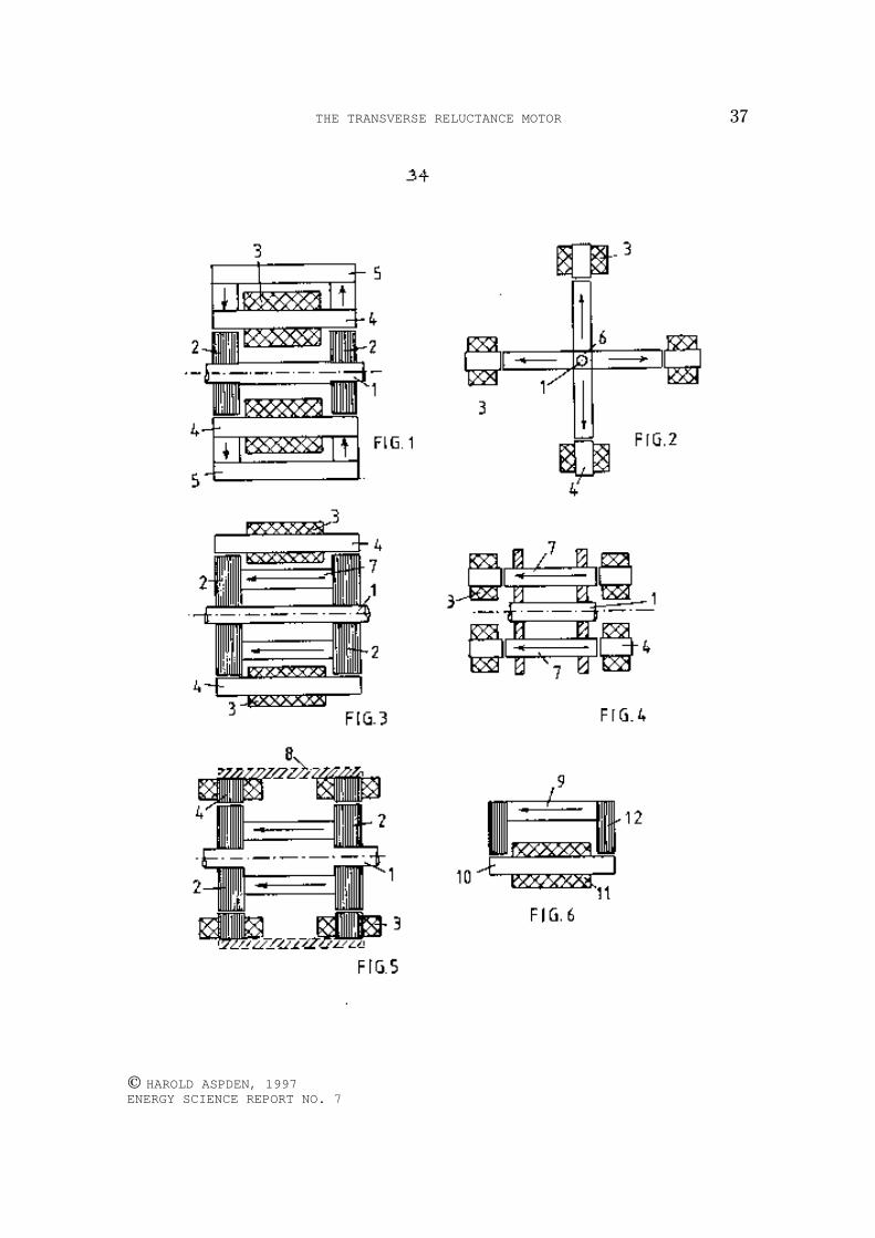
THE TRANSVERSE RELUCTANCE MOTOR 37
© HAROLD ASPDEN, 1997 ENERGY SCIENCE REPORT NO. 7
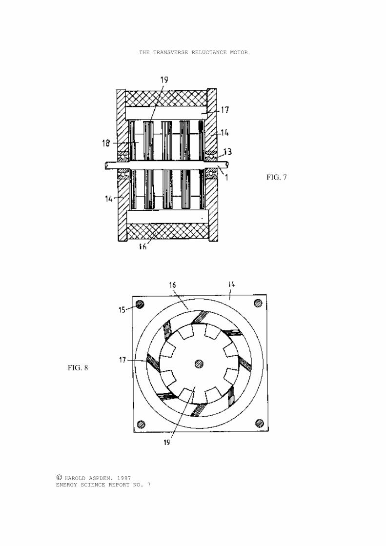
THE TRANSVERSE RELUCTANCE MOTOR
© HAROLD ASPDEN, 1997 ENERGY SCIENCE REPORT NO. 7
FIG. 7
FIG. 8

THE TRANSVERSE RELUCTANCE MOTOR
© HAROLD ASPDEN, 1997 ENERGY SCIENCE REPORT NO. 7
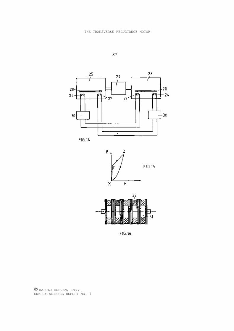
THE TRANSVERSE RELUCTANCE MOTOR
© HAROLD ASPDEN, 1997 ENERGY SCIENCE REPORT NO. 7