Embed Size (px)
Citation preview

Printed in England HA463296 Issue 5
EUROTHERMDRIVES
514C
Product Manual
Copyright Eurotherm Drives Limited 2001
All rights strictly reserved. No part of this document may be stored in a retrieval system, or transmittedin any form or by any means to persons not employed by a Eurotherm group company without written permission from Eurotherm Drives Ltd.Although every effort has been taken to ensure the accuracy of this document it may be necessary,without notice, to make amendments or correct omissions. Eurotherm Drives cannot accept responsibilityfor damage, injury, or expenses resulting therefrom.

WARRANTY
Eurotherm Drives warrants the goods against defects in design, materials and workmanship forthe period of 12 months from the date of delivery on the terms detailed in Eurotherm Drives
Standard Conditions of Sale IA058393C.
Eurotherm Drives reserves the right to change the content and product specification withoutnotice.
COPYRIGHT in this document is reserved to Eurotherm Drives Ltd.
INTENDED USERS
This manual is to be made available to all persons who are required to configure, install or service theequipment described herein or any other associated operation.

CONTROLLER
WARNING!
Signal and control terminals are insulated from the live supplies by double/reinforced(class 2) protective insulation. The heatsink is protected by bonding to earth (class 1insulation). This connection is the responsibility of the user.
Only qualified personnel who thoroughly understand the operation of this equipment andany associated machinery should install, start-up, or attempt maintenance of thisequipment. Non-compliance with this warning may result in serious personal injuryand/or equipment damage.
Never work on any control equipment or motors without first removing all power suppliesfrom the equipment.
These controllers are NOT Fail Safe. Control Failure may cause the motor to run at FullSpeed. The Speed control potentiometer and Run circuit are ineffective in thesesituations, BE SURE to provide an independent and positive means of disconnectingincoming power under emergency conditions.
It is the responsibility of the user to ensure the effectiveness and safety of operation intheir application of this product, especially under these fault conditions.
Caution
This equipment contains ESDESDESDESD (Electrostatic Discharge) sensitive parts. Observe staticcontrol precautions when servicing this device.
This equipment was tested before it left our factory. However, before installation andstart up, inspect all equipment for transit damage, loose parts, packing materials, etc.
Ruptured semiconductor devices may release toxic materials. Contact Eurotherm Drivesor the semiconductor manufacturer for proper disposal procedures for semiconductors orother material.
This controller is designed for use in a cubicle mount enclosure (see page 1-1).

FILTER
WARNING
AC supply filters produce earth leakage currents in excess of 3.5 mA.
AC supply filters contain capacitors allow at least 1 minute before servicing.
AC supply filters should be permanently earthed, use the second Protective Groundterminal as an independent earth.
Eurotherm Drives do not recommend the use of RCDs since the operation of RCDs can becompromised by the Filter Leakage. Special RCDs (type B - IEC755) are required due toAC and DC components flowing in the earth leakage current. All loads requiringprotection with an RCD would be at risk.

514CContents
Chapter 1 Product Overview 1-1Description...................................................................1-1Product Range..............................................................1-1540 TO 514C upgrade ................................................1-1EMC and the 'CE' Mark.................................................1-2Certificates ...................................................................1-4Product Identification ....................................................1-5Technical Specification..................................................1-6Environmental Requirements.........................................1-8EMC Technical Ratings .................................................1-9Product Code ...............................................................1-9
Chapter 2 Pre-Installation Planning 2-1Basic Wiring Diagrams .................................................2-1Terminal Descriptions ...................................................2-2Terminal Comparison 540/1 to 514C...........................2-4Block Diagram .............................................................2-1Functional Differences 514C - 540 ...............................2-1
Chapter 3 Installation Procedure 3-1Installation Precautions .................................................3-1Mechanical Installation .................................................3-1Electrical Installation .....................................................3-3Requirements for UL Compliance..................................3-5
Chapter 4 Setting-Up & Commissioning 4-1Option Switches ...........................................................4-1Potentiometers..............................................................4-2Basic Setting-up Procedure............................................4-3Running Performance Adjustments ................................4-7
Chapter 5 Diagnostics and Fault Finding 5-1Diagnostic Leds ............................................................5-1Drive Trips ...................................................................5-2Diagnostic Test Point Descriptions .................................5-2Troubleshooting ...........................................................5-4
Chapter 6 Service and Repair 6-1DISPOSAL ....................................................................6-1
Modification Record

Product Overview 1-1
514C Product Manual
Chapter 1 Product Overview
DESCRIPTION
The 514C controller is intended for use in an Industrial Environment, it should be mountedwithin an enclosure which provides protection to the controller and the user.
The controller should be permanently earthed at the terminals provided.
The 514C controller is designed to control the speed of a DC Shunt wound or permanentmagnet motor. It will provide control of the motor speed in all 4 Quadrants of operation.
The controllers are designed to operate from a single phase AC mains supply in the range of110 Vac to 415 Vac at 50 or 60 Hz. An auxiliary supply is required for internal power supplygeneration and main supply contactor sequencing. Coding is derived from the main powerterminals and is functional over the whole input voltage range.
The Speed of the DC Motor is controlled using a linear closed loop system with a feedbacksignal from either tachogenerator or armature voltage, the feedback source being switchselectable.
A current loop within the speed loop always ensures that controlled levels of current areapplied to the motor, actual levels being scaleable via programmable switches.
Motor protection is provided by a Stall detection circuit which will remove current from themotor after approximately 60 seconds.
Controller protection is provided by a Instantaneous Overcurrent trip circuit overridingcontrol in the event of a Short Circuit.
PRODUCT RANGE
Product Rating
514C/04 4A DC Full Load Current
514C/08 8A DC Full Load Current
514C/16 16A DC Full Load Current
514C/32 32A DC Full Load Current
540 TO 514C UPGRADE
The 514C is designed to be functionally equivalent to the 540 series controllers not a directreplacement. Comparisons between the two controllers connectors are included throughoutthe manual.
Chapter 2 describes the terminal connectors to the 514C controller, in that section on page 2.4is given a terminal to terminal comparison of 540/1 to 514C.

1-2 Product Overview
514C Product Manual
EMC AND THE 'CE' MARK
'CE' EMC Responsibility
The subject of CE marking and EMC is explored in more detail in a separate EurothermApplication manual entitled ‘EMC Installation Guidelines for modules and systems’, partnumber HA388879, available from your local Eurotherm Drives office. The followingsections are the minimum necessary for installation and basic understanding.
Eurotherm Drives are adhering to the CEMEP recommendations on ‘CE’ marking for EMC.According to SI No. 2372, implementing the EMC directive into UK law, the requirement toCE mark for EMC, applies only to relevant apparatus that has ‘intrinsic function’ to theend user and which is placed on the market (supplied). The majority of drivemodules/systems sold by Eurotherm Drives will be incorporated into a highersystem/apparatus or machine which includes (at least) the motor, cable and a driven loadbefore providing intrinsic function to the end user. As such the majority of Eurotherm Drivesproducts are categorised as components (CEMEP validity field 2) and it would be incorrectfor Eurotherm Drives to apply the CE mark or produce an EC Declaration of Conformity inrespect of EMC. It is the manufacturer/supplier/installer of the relevant apparatus (with theintrinsic function to the end user) who must demonstrate conformance to the EMC directive
However, in a minority of cases, single drives may have intrinsic function to the end user. Anexample is that of ‘add on’ intrinsic function, where an existing fixed speed motorapplication (such as a fan or a pump) is converted to variable speed with an add on drivemodule (CEMEP validity field 1). In this application Eurotherm Drives CE mark its drivemodule and issue an EC declaration of conformity. Because the validity of the ‘CE’ mark forEMC is not known when the product is manufactured, the ‘CE’ mark will be applied via theproduct manual, and will not be on the product label. From 1997, when the ‘CE’ mark for theLow Voltage Directive becomes mandatory, the CE mark will appear on the product label, butits validity for EMC can only be identified from the product manual.
The validity of the ‘CE’ mark can be identified from the flowchart in figure A, refer to SI No.2372 for clarification of relevant apparatus.
To assist manufacturers/suppliers/installers of relevant apparatus, the Eurotherm Drive 514Cmodules are EMC compliant to EN50081-1 (1992), EN50082-1 (1992), EN50081-2 (1994)and prEN50082-2 (1992), when fitted with the specified filter and installed according to theseinstructions, as confirmed by the Manufacturers EMC declaration to be found at the end ofthis chapter. Manufacturers/suppliers/installers of relevant apparatus (CEMEP validity fields3 & 4) may use this compliance as a basis for their own justification of overall compliancewith the EMC Directive.
It must be clearly understood by the customer before installation commences who is legallyresponsible for conformance with the EMC Directive. Misappropriation of the CE mark is acriminal offence.

Product Overview 1-3
514C Product Manual
Figure A Eurotherm EMC ‘CE’ Mark Validity Chart
THE E.D. EC DECLARATION OF CONFORMITY FOR EMC IS VALID FOR THE SPECIFIED ED MODULE
START
IS E.D. MODULE RELEVANT APPARATUS
WITH INTRINSIC FUNCTION TO END USER (CEMEP
VALIDITY FIELD 1)
NO
YES
FIT THE SPECIFIED E.D. EMC FILTER
WILL THE E.D. PRODUCT BE INSTALLED
ACCORDING TO THE INSTALLATIONGUIDELINES
NO
YES
E.D. = EUROTHERM DRIVES LIMITED
EMC 'CE' MARK CAN BE APPLIED TO E.D.
MODULE TO GENERIC EMC STANDARDS:
EN50081-1(1992), EN50081-2(1994) AND
EN50082-1(1992) (AND prEN50082-2(1992)).
EMC INSTALLATION GUIDELINES
STATED IN MANUAL
EMC CHARACTERISTICS STATED IN MANUAL
OPTIONAL E.D. FILTERS AVAILABLE TO ASSIST USERSIN CONFORMANCE WITH THE
EMC DIRECTIVE
A GLOBAL EMC SOLUTION
MAYBE ADVANTAGEOUS
CEMEP VALIDITY FIELDS
2, 3 AND 4
THE E.D. MANUFACTURERS DECLARATIONFOR EMC IS VALID FOR THE SPECIFIEDMODULE WHEN INSTALLED CORRECTLY
NO EMC 'CE'MARK APPLIED TO E.D MODULE
MANUFACTURER/SUPPLIER/INSTALLERS
RESPONSIBILITY TO CONFORM WITH EMC DIRECTIVE.
E.D. EMC CHARACTERISTICS AND MANUFACTURERSDECLARATION MAY BE USED AS A BASIS IN THE
RELEVANT APPARATUS
OVERALL PRODCT JUSTIFICATION

1-4 Product Overview
514C Product Manual
CERTIFICATES
514C
EC DECLARATIONS OF CONFORMITY
Date CE marked first applied: 06/02/1997
Issued for EMC Directive Low Voltage Directive The drive is CE
compliancewith the EMCDirective whenthe unit is usedas relevantapparatus.
In accordance with the EEC Directive89/336/EEC and amended by 92/31/EEC and93/68/EEC, Article 10 and Annex 1, (EMC
DIRECTIVE)
We Eurotherm Drives Limited, address asbelow, declare under our sole responsibility
that the above Electronic Products wheninstalled and operated with reference to the
instructions in the Product Manual (providedwith each piece of equipment) is in accordance
with the relevant clauses from the followingstandards:-
BSEN50081-2 (1994), BS EN50081-1 (1992)BSEN50082-1# (1998), BSEN50082-2#* (1995)
In accordance with the EEC Directive73/23/EEC and amended by 93/68/EEC,
Article 13 and Annex III, (LOW VOLTAGEDIRECTIVE)
We Eurotherm Drives Limited, address asbelow, declare under our sole responsibility
that the above Electronic Products wheninstalled and operated with reference to the
instructions in the Product Manual
(provided with each piece of equipment), is inaccordance with the following standard :-
EN50178 (1998)
marked inaccordance withthe low voltagedirective forelectricalequipment andappliances in thevoltage rangewhen installedcorrectly.
MANUFACTURERS DECLARATIONS
This is EMC Declaration Machinery Directive Since the
provided to aidyourjustification forEMCcompliancewhen the unitis used as acomponent.
We Eurotherm Drives Limited, address asbelow, declare under our sole responsibility
that the above Electronic Products wheninstalled and operated with reference to the
instructions in the Product Manual (providedwith each piece of equipment) is in accordancewith the relevant clauses from the following
standards:-
BSEN50081-2 (1994), BS EN50081-1 (1992)BSEN50082-1# (1998), BSEN50082-2#*
(1995)
The above Electronic Productsare components to be incorporated into
machinery and may not be operated alone.The complete machinery or installation usingthis equipment may only be put into service
when the safety considerations of the Directive89/392/EEC are fully adhered to.
Particular reference should be made toEN60204-1 (Safety of Machinery - Electrical
Equipment of Machines).All instructions, warnings and safety
information of the Product Manual must beadhered to.
potential hazardsare mainlyelectrical ratherthan mechanical,the drive does notfall under themachinerydirective.However, we dosupply amanufacturer'sdeclaration for
when the drive isused(as acomponent) inmachinery.
Dr Martin Payn (Conformance Officer)
* For information only.
# Compliant with these immunity standards without specified EMC filters.
EUROTHERM DRIVES LIMITED An Invensys CompanyNEW COURTWICK LANE, LITTLEHAMPTON, WEST SUSSEX BN17 7RZTELEPHONE: +44(0)1903 737000 FAX: +44(0)1903 737100
Registered Number: 1159876 England. Registered Office: Invensys House, Carlisle Place, London SW1P 1BX
File Name: I:\Manuals\514C Controller\HA463296 Issue 5\HA463296.doc © 2001 EUROTHERM DRIVES LIMITED
ISS: DATE DRN: MP CHKD: J.Mc DRAWING NUMBER: HK463413.919
A 06/02/97
EUROTHERMDRIVES
TITLE:
Declarations of ConformitySHT 1
OF1 SHTS

Product Overview 1-5
514C Product Manual
PRODUCT IDENTIFICATION
FIELD TERMINALS
HEATSINK
LEGENDPLATE
CONTROL
FIXINGPOINTS
PCB
PROTECTIVEGROUND
RAMP UP
RAMP DOWNSPEED PROPORTIONAL
CURRENT LIMIT
IR COMPENSATION
MAX SPEED CALIBRATION
ZERO SPEED ADJUSTZERO SPEED THRESHOLD
SPEED INTEGRAL
CURRENT PROPORTIONAL
CURRENT INTEGRAL
P1P2P3P4P5P6P7P8P9
P10P11P12
L2 STALL TRIPL1 POWER ON
L3 OVERCURRENT
L4 PLL LOCK
L5 CURRENT LIMIT
POWERPCB
AUXILIARY
POWERTERMINALS
SW1
SW2 SW3 SW4
A1 A2 A3 A4A1 A2 A3 A4A1 A2 A3 A4A1 A2 A3 A4
EUROTHERMDRIVES
514C
CAUTION
CAUTION
AVERTISSEMENT
CAUTION
1
ONSW1
TenthsUnitTens
1 2 3 4 5 6 7 8 9 10
FL1 FL2 F- F+ L2/N L1 A+ A-
DIAGNOSTIC SOCKET
Option Switches
Current CalibrationSwitches
Before Switching ON Refer to the Manual for Installation and Safety,Switch and Transformer Setting Information.
Risk of Electric Shock - More than One Disconnect Switch may be Requiredto De-energise the Equipment Before Servicing
Risque de decharge electrique. La coupure de plusieurs interrupteurs poutetre necessaire avant utilisation - voir le schema
Compatible with Type B RCD Protection Devices Only
POTENTIOMETERSDIAGNOSTIC LEDS
CONTROL TERMINAL BLOCK
SUPPLY AUXILIARY SUPPLYSELECTOR SWITCH
24 23 22 21 20 19 18 17 16 15 14 13 12 11 10 9 8 7 6 5 4 3 2 1

1-6 Product Overview
514C Product Manual
TECHNICAL SPECIFICATION
General
SPEED CONTROLControl Action Closed Loop with Proportional Integral Control and
Adjustable StabilitySpeed Feedback Armature Voltage Tachogenerator
100% Load Regulation 2 % Typical 0.1 % Typical
Maximum Torque/Speed Range 20:1 100:1
Overload 150% for 60 seconds.
TORQUE CONTROL
Control Action Closed Loop with Proportional Integral Control.
Accuracy 2 %
Overspeed Inherent.
Overload None 100% continuous (consideration must be givento motor when operating at low speed).
INPUTS / OUTPUTS
Analogue Setpoint Ramp 0 to ±10V 100 Kohm
Inputs Positive Trim Setpoint 0 to ±10V 100 Kohm
Negative Trim Setpoint 0 to ±10V 100 Kohm
Current Limit 0 to +7.5V 50 Kohm
Current Demand 0 to ±10V 100 Kohm
Tachogenerator Input 0 to ±350Vdc 220 KohmThermistor /Microtherm Input
<200 ohm = Normal>1800 ohm = Overtemperature
5 Kohm
Outputs Setpoint Ramp 0 to ±10V 5 mA
Analogue Total Setpoint 0 to ±10V 5 mA
Speed 0 to ±10V 5 mA
Current Demand 0 to ±10V 5 mA
Current Meter 0 to ±5V (0 to Ical) 5 mABipolar or Modulus See SW1/8
+10V Reference +10V 5 mA
-10V Reference - 10V 5 mA
Digital Run +10 to +24V 100 Kohm
Inputs Enable +10 to +24V 100 Kohm
Stall Override +10 100 Kohm
Digital Health +24V 50 mA Source
Outputs Zero Speed or Setpoint +24V 50 mA Source

Product Overview 1-7
514C Product Manual
Electrical Ratings
INPUT RATINGS SYMBOL 514C/04 514C/08 514C/16 514C/32
Supply Voltage Vs 110 - 480 Vac ± 10%Maximum SupplyVoltage (Derived from
480Vac L - L Non earth referenced (IT)or earth referenced (TN)
Three Phase Supply) 480Vac L - N Earth referenced (TN)Supply Current Is 6A 12A 24A 48A
Supply Frequency fs 50/60 Hz ñ 5 Hz
Auxiliary Supply Vaux 110/120 or 220/240 Vac ±10%
Aux. Supply Current Iaux 3A (Includes Contactor Coil Current)
Contactor CoilCurrent
3A Maximum
Installation Category Overvoltage Category III
Earth Leakage Without Filter - 5mA (1)
Current at 480Vac With Filter - 50mA
OUTPUT RATINGS
Nominal ArmatureVoltage Va
90 Vdc at 110/120 Vac
180 Vdc at 220/240 Vac
320 Vdc at 380/415 VacMaximum ArmatureCurrent
Ia 4A dc ±10% 8A dc ±10% 16A dc ±10% 32A dc ±10%
Armature CurrentCalibration 100%
Ical 0.1 to 4A
in 0.1A steps
0.1 to 8A
in 0.1A steps
0.1 to 16A in 0.1A
steps
0.1 to 32A
in 0.1A steps
Nominal Motor Power Pm 1.125kW 2.25 kW 4.5 kW 9 kW
at 320 Vdc Armature HP 11/2 HP 3 HP 6 HP 12 HP
Overload 150% for 60 seconds
Field Current If 3 A dc
Field Voltage Vf 0.9 X Supply Voltage (Vs)Maximum ArmatureForm Factor
1.5
Thyristor I2t 300 A2sTypical ControllerDissipation at Ia 100%
15W (2) 25W (2) 50W (2) 75W (2)
UL Listed Rating @180V dc
HP 1/2 HP 1 HP 3 HP 5 HP
Notes:- (1) Permanent earthing mandatory.
(2) See page 3-2 for filter watt loss information.

1-8 Product Overview
514C Product Manual
Mechanical
514C/04 514C/08 514C/16 514C/32
Overall Width 160mm
Overall Height 240mm
Overall Depth 90mm 90mm 130mm 130mm
Weight 1.6Kg 1.6Kg 3.0Kg 3.0Kg
Airflow Clearance 75mm Above and Below
Mounting Centres 210mm Vertical x 148mm Horizontal
Control Terminals -1 to 24
Screw Terminals will accept 2.5mm2 stranded wire.
Terminal Tightening Torque 0.45 Nm, 4.0 lbf-in.
Auxiliary SupplyTerminals - A1 to A4
Screw Terminals will accept 4mm2 stranded wire.
Terminal Tightening Torque 0.5 Nm, 4.5 lbf-in.
Field Terminals - FL1,FL2, F-, F+
Screw Terminals will accept 4mm2 stranded wire.
Terminal Tightening Torque 0.5 Nm, 4.5 lbf-in.
Power Terminals -L2/N, L1, A+, A-
M5 Studs with Clamp.
Terminal Tightening Torque 2.7 Nm, 24 lbf-in.
Earth (Grounding)Terminals
M5 Cheese Head Screw.
Terminal Tightening Torque 7.1 Nm, 63 lbf-in.
ENVIRONMENTAL REQUIREMENTS
Enclosure Chassis Mounting IP00 (UL open-type)
Operating Temperature 0 to +40oC. (Derate 1.5%/Degree above 40oC).
Humidity 85% R.H. at 40oC. (Non-condensing).
Altitude Above 1000m derate at 1% / 100m.
Storage Temperature -25oC to +55oC.
Pollution Pollution Degree 2.
Transport Temperature -25oC to +70oC.
Overvoltage III
Product Overview 1-9
514C Product Manual
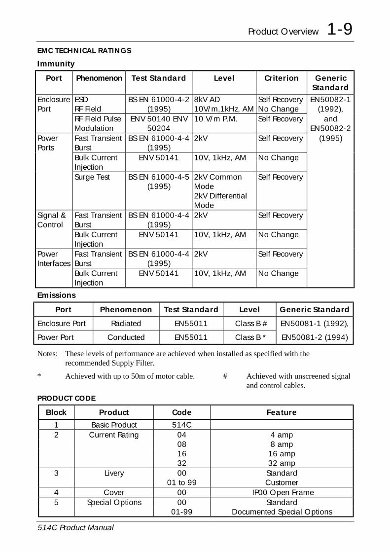
EMC TECHNICAL RATINGS
Immunity
Port Phenomenon Test Standard Level Criterion GenericStandard
EnclosurePort
ESDRF Field
BS EN 61000-4-2(1995)
8kV AD10V/m,1kHz, AM
Self RecoveryNo Change
EN50082-1(1992),
RF Field PulseModulation
ENV 50140 ENV50204
10 V/m P.M. Self Recovery andEN50082-2
PowerPorts
Fast TransientBurst
BS EN 61000-4-4(1995)
2kV Self Recovery (1995)
Bulk CurrentInjection
ENV 50141 10V, 1kHz, AM No Change
Surge Test BS EN 61000-4-5(1995)
2kV CommonMode2kV DifferentialMode
Self Recovery
Signal &Control
Fast TransientBurst
BS EN 61000-4-4(1995)
2kV Self Recovery
Bulk CurrentInjection
ENV 50141 10V, 1kHz, AM No Change
PowerInterfaces
Fast TransientBurst
BS EN 61000-4-4(1995)
2kV Self Recovery
Bulk CurrentInjection
ENV 50141 10V, 1kHz, AM No Change
Emissions
Port Phenomenon Test Standard Level Generic Standard
Enclosure Port Radiated EN55011 Class B # EN50081-1 (1992),
Power Port Conducted EN55011 Class B * EN50081-2 (1994)
Notes: These levels of performance are achieved when installed as specified with therecommended Supply Filter.
* Achieved with up to 50m of motor cable. # Achieved with unscreened signal and control cables.
PRODUCT CODE
Block Product Code Feature
1 Basic Product 514C2 Current Rating 04 4 amp
08 8 amp16 16 amp32 32 amp
3 Livery 00 Standard01 to 99 Customer
4 Cover 00 IP00 Open Frame5 Special Options 00 Standard
01-99 Documented Special Options

2-1 Pre-Installation Planning
514C Product Manual
Chapter 2 Pre-Installation PlanningBASIC WIRING DIAGRAMS
Basic Connection
FS5 FS6
1 3 4 5 6 7 8 9 10 11 12 14 15 16 19 2313
10K
SPEED
FS1
L1 L2/N
FS2
A4
RUN
TACHOGENERATOR
Branch Protection (Fuses or Circuit Breaker)
10K
10K100%
CURRENTLIMIT
EXTERNAL
(Optional)
SETPOINT
Speed RelayHealth Relay
PE
0 to
24 A3 A2 A1
AC Supply Contactor
22
Microtherm
A+ A- F+ F-
��
FL1 FL2
FS3 FS4
DC Motor
OPTIONAL
20
ENABLE
Auxillary AC Supply
�
Mains Supply
PEGRD
Signal Ground
1
2
GND
1 It is recommended that the “0V/common” be connected to protective earth/ground for safetyreasons. In a system comprising of more than one controller, the 0V/common” signalsshould be connected together and joined to protective earth/ground at one point only.
2 Stall override link between terminals 14 and 15 required when using controller in currentcontrol.
EMC Connections With Filter
ProductL1L2PE
F+F-
A+A-PE
��
�������Screened Cable
AC Supply
��
FL1FL2
Filter
Screened Cable
PE
A3A4A1A2
For more guidelines/details, see Eurotherm Drives EMC Installation Guidelines for Modules andSystems part number HA388879 available from your local Eurotherm Drives office.

Pre-Installation Planning 2-2
514C Product Manual
TERMINAL DESCRIPTIONS
Control TerminalsTERMINAL FUNCTION DESCRIPTION NOTES
T1 Tacho Feedback Motor Mounted Tachogenerator Input.Proportional to Motor Speed.
+350 Vdc Max. Approx220 kohm.
T2 Not ConnectedT3 Speed Meter Output Analogue Output,
0 to ±10V for 0 to ±100% Speed.5mA outputS/C protected
T4 DO NOT USE Pending Change.T5 Run Input Digital Input to Run Controller.
+24V to Run.0V to Stop.
T6 Current MeterOutput
Analogue Output, 0 to +7.5V = ±150%Calibrated CurrentSW1/5 Off = BipolarSW1/5 On = Magnitude
5mA outputS/C protected
T7 Torque/CurrentLimit Input
Analogue Input,0 to +7.5V = 0 to 150% of CalibratedCurrent.
approx.100 kohm
T8 0V Common Analogue / Digital Signal CommonT9 Setpoint Ramp
OutputAnalogue Output,0 to ±10V = 0 to ±100% RampedSetpoint.
5mA outputS/C protected
T10 Positive Trim SpeedSetpoint Input
Analogue Input,0 to ±10V = 0 to ±100% Speed.
approx.100 kohm
T11 0V Common Analogue / Digital Signal Common.T12 Total Setpoint Sum
OutputAnalogue Output,0 to ±10V = 0 to ±100% Speed.
5mA outputS/C protected
T13 Setpoint Ramp Input Analogue Input,0 to +10V = 0 to 100% ForwardSpeed.0 to -10V = 0 to 100% Reverse Speed.
approx.100 kohm
T14 +10V ReferenceOutput
Analogue Output,+10V Reference for Speed/ CurrentSetpoints.
5mA outputS/C protected
T15 Stall Override Input Digital Input to Override Stall Detection+10V = Override.
approx.100 kohm
T16 -10V ReferenceOutput
Analogue Output,-10V Reference for Speed/ CurrentSetpoints.
5mA outputS/C protected
T17 Negative TrimSpeed SetpointInput
Analogue Input,0 to +10V = 0 to 100% Reverse Speed0 to -10V = 0 to 100% Forward Speed.
approx.100 kohm

2-3 Pre-Installation Planning
514C Product Manual
TERMINAL FUNCTION DESCRIPTION NOTES
T18 Current DemandInput / Output
Analogue Input or Output:SW1/8 'ON' = Current DemandOutput.SW1/8 'OFF' = Current Demand Input.0 to ±7.5V = 0 to ±150% Current.
5mA outputS/C protected approx.100 kohm.
T19 Health Output Digital Output,+24V = Healthy.
50mA SourceShort Circuit Protected.
T20 Enable Input Digital Input to Enable Controller.+10V to +24V to Enable.0V to Disable.
100k approx.
T21 Inverted SetpointSum Output
Analogue Output,0 to -10V = 0 to 100% Forward Speed.
5mA outputS/C protected.
T22 Thermistor /Microtherm Input
Motor Thermistor or Microtherm Sensor<200 ohm to 0V = Normal.>1800 ohm to 0V= Overtemperature.
5k approx.
T23 Zero Speed Output/Zero SetpointOutput
Digital Output,+24V = Stopped/Zero Setpoint. 0V = Running/Non zero setpoint.
50mA SourceShort Circuit Protected.
T24 +24V +24V Supply Output. 20mA. For use on thedrive only.
Caution
The +24v supply from the drive (terminal T24) is for use with the drive only. Itshould be used with the RUN circuit (terminal 5) to control the drives internalrelay to switch the contactor and can be used with the ENABLE circuit (terminalT20).
DO NOT use the +24v supply to power any circuit or device external to thedrive. This includes external relays, PLC’s, and any other equipment.
Using the +24v external to the drive could result in drive malfunction or damage,damage to connected equipment, and could endanger personnel.

Pre-Installation Planning 2-4
514C Product Manual
TERMINAL COMPARISON 540/1 TO 514C
Function Terminal540/1
Terminal514C
Common A1 T8
Armature Current (Direct) A2 -
Setpoint Ramp Reset A3 -
Setpoint Ramp Input A4 T13
Setpoint Ramp Output A5 T9
Setpoint Input 1 - Positive Trim Speed Setpoint I/P A6 T10
Setpoint Input 2 A7 -
Inverted Sub-Total Output - Inverted Setpoint Sum O/P A8 T21
Setpoint Input 3 (Inverted) - Negative Trim Speed Setpoint I/P A9 T17
Total Setpoint A10 T12
+10V Reference A11 T14
-10V Reference A12 T16
Common B1 T11
Tachogenerator Input B2 T1
Current Demand Isolate B3 -
Current Demand Output B4 T18
Auxiliary Current Demand Input B5 T18
Select Auxiliary Current Input B6 -
Auxiliary Current Limit Positive B7 -
Main Current Limit B8 T7
+10V Reference B9 T14
Auxiliary Current Limit Negative B10 -
Buffered Speed Output B11 T3
Buffered Current Output B12 T6

2-5 Pre-Installation Planning
514C Product Manual
Function Terminal540/1
Terminal514C
Common C1 T8/11
Thermistor C2 T22
Auxiliary Enable C3 -
+24V C4 T24
Enable C5 T20
Maintain C6 -
Start / Run C7 T5
Ready Output C8 -
Zero Speed Output C9 T23
Drive Operational / Health C10 T19
+24V C11 T24
Unused C12 -
DO NOT USE Pending Change - T4
Stall Override - T15
Switches
Function 540/1 514C
Speed Calibration No Yes SW1/2
Tachogenerator or Armature Voltage No Yes SW1/3
Zero Output Speed or Setpoint No Yes SW1/4
Current Bipolar or Modulus Yes S1 Yes S1/5
Ramp Isolate Yes S3 Yes SW1/6
Standstill Yes S2 Yes SWQ1/7
Current Demand Output or Current Demand Input No Yes SW1/8
Contactor Dropout on Overcurrent No Yes SW1/9
Standstill Comparator Source No Yes SW1/10
Ramp Rate Yes S4 No
Current Calibration No Yes SW2/3/4

Pre-Installation Planning 2-6
514C Product Manual
Auxiliary Supply Terminals
TERMINAL FUNCTION DESCRIPTION NOTES
A1 AC SupplyContactor Coil.
AC Supply to AC SupplyContactor Switched Live.
540/1 Terminal D12
A2 AC SupplyContactor Coil.
AC Supply to AC SupplyContactor Neutral.
540/1 Terminal D11
A3 Auxiliary AC SupplyNeutral.
Auxiliary Supply for PowerSupplies and Contactor.
540/1 Terminal D10
A4 Auxiliary AC SupplyLive.
Auxiliary Supply for PowerSupplies and Contactor.
540/1 Terminal D9
Power Terminals
TERMINAL FUNCTION DESCRIPTION NOTES
L1 AC Input Line 1 Mains Supply Line 1 Input L1
L2/N AC Input Line 2/Neutral
Mains Supply Line 2 Input orNeutral
L2/N
A+ Armature Positive Motor Armature Positive Output. A+
A- Armature Negative Motor Armature NegativeOutput.
A-
Ground
Field Terminals
TERMINAL FUNCTION DESCRIPTION NOTES
F- Field Negative Motor Field Negative DC Output 540/1 Terminal D7
F+ Field Positive Motor Field Positive DC Output 540/1 Terminal D5
FL2 Field Rectifier Supply Mains Supply Input Field Rectifier 540/1 Terminal D3
FL1 Field Rectifier Supply Mains Supply Input Field Rectifier 540/1 Terminal D1
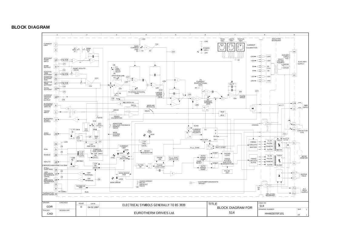
BLOCK DIAGRAM
IA>0
IA=0
ISA -10V
10V
PHASEANGLE
-1+1
MAINSUPPLY
L2/N
L1
A.C.C.T.
P6CURRENT
PROPORTIONAL
P7CURRENTINTEGRAL
GAIN
AUTO LOGIC
RESET
RAMPRANGEAUTO
RAMPRANGE
RAMP
GENERATIONEND STOP
PULSE&FIRING
P.L.L. SYNC
MDEMAND
S
POLARITY
SCAN
CURRENT
SOFT START
GATINGTH5-8
CIRCUITSFIRING
SLAVE
-+
-
+
SLAVE
-
+
SUPPLYFIELD
A.C
-
+
FIELDMOTOR
A-
ARMATUREMOTOR
HEATSINKMOUNTED ON
+
CIRCUITS
FIRING
MASTER
MASTER-
TH1-4+
-
RBA+
N
COILCONTACTOR
L
-10V
+10V
1
6
+1
12
10 ++
G
-11V
++
+11V
P10
COMPIR
SPEED PROP GAINP3
-2%
RAMP ISOLATE9
13
4
7
RATEUP DOWN
RATE
+2%
BIPOLAR/MODULUS
MAX SPEED CAL
P8 GAIN
+10V
-
-
+
+10V
8
11
16
0V
14
15
19
RUN
INTERNAL
-10VINTERNAL
ORGATE
3 I/P
+10V
NO FAULT
TRIP
OVERCURRENT
OVERCURRENT
+24V
5
GATEAND4 I/P
+24V
0V
23
OUTPUTZERO
PLL SYNC+24V
3
OR2 I/P
GATE
2 I/PAND GATE
10%ZEROSPEED
S.PZERO
STALL STALLDETECTION
SYSTEMENABLE
MAIN
0.5%ZERO
THRESHOLD
P12
DETECTOR256
-90FILTER PHASE
LOCK LOOP
P.L.L. SYNDIVIDE
CURRENTLIMIT
RAMPINPUT
RAMPOUTPUT
NEGATIVETRIM
TOTALSETPOINT
CURRENTDEMAND
TACHOINPUT
SETPOINT
INPUT/
BUFFEREDCURRENT100%=5V
BUFFEREDSPEED
RUN
ENABLE
STALLOVER RIDE
+10VPRECISIONREFERENCE(10mA)-10VPRECISIONREFERENCE(10mA)
HEALTH
S.O.T.
BOUNDARYISOLATION
CODING
C
COM P
VA50
A3
0V (SIGNAL)
LED3
LED2
LED5
LIMITCURRENT
SYNC
LED4
PLL
-1+1
-1
ZCUSTOMER DIAGNOSTICSOCKET
P2P1
20
LOGIC ENABLESTANDSTILL
Z7
Z8
ARMATUREVOLTAGE FEEDBACKENABLE
OUTPUT
+1
17
18
POSITIVETRIMSETPOINT
SETPOINT
SPEED
P11ZERO
ADJUST
Z26
Z16
SPEEDCALIBRATION
Z27
21
SW1/6
INVERTEDSETPOINTSUM
ZEROOUTPUT
SELECT
SW1/4
SW1/10
24
SW1/7
22THERMISTOR/MICROTHERM
Z6
SW1/2
SW1/3
SW1/1
SW1/5
0V
OVERCURRENTRELAYDROPOUTSW1/9
F+
F-
A1
A2
GATEAND2 I/P
RESETGENERATOR
-+ ++
FILTER
Z11
FILTER
Z12
FILTERZ14
Z15
Z18
Z9
Z5
Z2
Z3
FL1
FL2
+24V
POWERLED 1
-24V
CURRENT
CALIBRATION
+24V
+15V
0V
+24V
+15V
0V
0V
(SIGNAL)
0V
-15V
-24V
-15V
-24V
ISOLATIONBOUNDARY
FUSESUPPLY
AUXILIARY
A4
AUXILIARYSUPPLY
REQUIRED
SELECTVOLTAGE
1
1
USED ON
DRAWING NUMBER SHT.
OF
987654321
514
HH463070F101
TITLEDRAWN CHECKED
CAD
DATE
TRACED DESIGN APP.
GDR
514EUROTHERM DRIVES Ltd.
ISSUE
(ENERGISED WHEN DRIVE O.K) 50mA.
THERMISTORTRIP
SPEED
P4 SPEED INTEGRAL
+
Z17
++
-10V
-
CURRENTDEMANDISOLATE
SW1/8
Z19
Z24P5LIMIT
CURRENT
0V
MAIN7.5V
+
0V
IMA
0V
GAIN
Z25
++
+++
123
456789 00 1
23
456
89
7
9876 5
32
10
4
SW3UNITS
SW4TENTHS
SW2TENS
0V
+-
CLOCK M1E/S
S1
IA=0
S
M
COM P
PULSEOSC
T5-T8
SLAVE
PULSE
TRANS'FR
T1-T4
SLAVE
PULSE
TRANS'FR
RLA
D 04.02.1997ELECTRICAL SYMBOLS GENERALLY TO BS 3939
BLOCK DIAGRAM FOR
OUTPUT
220/240
110/120

2-9 Pre-Installation Planning
514C Product Manual
FUNCTIONAL DIFFERENCES 514C - 540
Feature 540 Series 514C
Overload Inverse Time reduced CurrentLimit.
Stall Detection & Timed Inhibit.
Overload 200% for 10 seconds. 150% for 60 seconds.Overcurrent - 300% Instantaneous Trip.Ramp 0.1 to 2 secs or 1 to 20 secs. 1 to 40 seconds.Ramp Reset Internal & External. Internal.Speed SetpointInputs
Ramp, Input No 1, Input No 2and Inverted Input No 3.
Ramp, Positive Trim & Negative TrimInput.
Auxiliary CurrentClamp Positive
Auxiliary Current Limit of PositiveDemand.
Not Provided.
Auxiliary CurrentClamp Negative
Auxiliary Current Limit ofNegative Demand.
Not Provided.
Current DemandOutput
Speed Loop Current DemandOutput.
Current Demand O/P or Ext. CurrentDemand I/P.
Current DemandIsolate
Isolates Speed Loop CurrentDemand from Current Path.
DIL Switch Selectable.
External CurrentDemand I/P
Additional Current Demand. Current Demand O/P or Ext. CurrentDemand I/P.
Current DemandConnect
Enable Input of External CurrentDemand.
Not Provided.
Armature CurrentOutput
External IR Compensation viaArmature Current Output.
Internally provided.
Auxiliary Enable External Trip / Enable. Not Provided.Ready Drive Ready Output. Not Provided.Stop Input Maintain for Momentary Start. Not Provided.Field Fail Field Current detector. Not Provided.Stack Fuses Semiconductor Fusing. Not Provided.Relays Output Sink unprotected. Output Source Short Circuit Protected.EMC Complies with EMC Directive.LVD Complies with Low Voltage Directive.
WARNING
THE 514C IS NOT A DIRECT REPLACEMENT FOR THE 540/1 IT ISFUNCTIONALLY EQUIVALENT.
NOTE WHEN A 514C IS USED TO REPLACE A 540 WITH THE HEALTH AND/OR ZEROSPEED RELAYS UTILISED THE RELAYS MUST BE RECONNECTED BETWEENOUTPUT AND SIGNAL COMMON NOT +24V.

Setting up & Commissioning 3-1
514C Product Manual
Chapter 3 Installation ProcedureINSTALLATION PRECAUTIONS
Before connecting AC supplies to this equipment.
1) Ensure good airflow over the heatsink. Maintain clearance of 75mm above and belowcontroller. For safety maintain a clearance of 20mm at the sides of the controller.
2) Operating temperature range does not exceed 0 to +40øC.
3) Controller is used in a Pollution Degree 2 environment.
4) Avoid vibration.
MECHANICAL INSTALLATION
D A
FC
(measurement for 514C/04 and 08)
C(measurement for 514C/16 and 32)
G
RAMP UP
RAMP DOWNSPEED PROPORTIONAL
CURRENT LIMIT
IR COMPENSATION
MAX SPEED CALIBRATION
ZERO SPEED ADJUSTZERO SPEED THRESHOLD
SPEED INTEGRAL
CURRENT PROPORTIONAL
CURRENT INTEGRAL
P1P2P3P4P5P6P7P8P9P10P11P12
L2 STALL TRIP
L1 POWER ON
L3 OVERCURRENT
L4 PLL LOCK
L5 CURRENT LIMIT
SW1
SW2 SW3 SW4
EUROTHERMDRIVES
514C
CAUTION
CAUTION
AVERTISSEMENT
CAUTION
1
ON
TenthsUnitTens
1 2 3 4 5 6 7 8 9 10
FL1 FL2 F- F+ L2/N L1 A+ A-
Before Switching ON Refer to the Manual for Installation and Safety,Switch and Transformer Setting Information.
Risk of Electric Shock - More than One Disconnect Switch may be Requiredto De-energise the Equipment Before Servicing
Risque de decharge electrique. La coupure de plusieurs interrupteurs poutetre necessaire avant utilisation - voir le schema
Compatible with Type B RCD Protection Devices Only
E
B
PRODUCT OVERALLDIMENSIONS
FIXINGCENTRES
SIZE SLOT DETAIL
A B C D E F G
514C/04 240mm 160mm 90mm 210mm 148mm M6 15mm 7mm
514C/08 240mm 160mm 90mm 210mm 148mm M6 15mm 7mm
514C/16 240mm 160mm 130mm 210mm 148mm M6 15mm 7mm
514C/32 240mm 160mm 130mm 210mm 148mm M6 15mm 7mm

3-2 Setting up & Commissioning
514C Product Manual
FilterFilterFilterFilter
L1 L2PE PELINE
LOAD
4 Holes M6 Insert
4 Holes M6 Clearance
230mm Leads
M5 Ring Lugs PE L1 L2BlackRedGreen
/Yellow
C E LA
HB
D
W
Product Filter WattLoss
Overall Dimensions FixingCentres
ProductFixing
Terminal
L W H E A B C D
514C/04 CO389113 18W 264 165 45 240 253 120 210 148 4mm2
514C/08 CO389113 18W 264 165 45 240 253 120 210 148 4mm2
514C/16 CO389113 18W 264 165 45 240 253 120 210 148 4mm2
514C/32 CO389114 36W 264 165 70 240 253 120 210 148 6mm2

Setting up & Commissioning 3-3
514C Product Manual
Installation Information
MOTORMOTORMOTORMOTOR
1) Ensure motor is mechanically secure and mounted according to manufacturersspecifications and practice.
2) Inspect brush gear, ensure commutator is in good condition and brushes are free to movein brush box and in good condition.
3) Check obstructions in motor vents to maintain cooling air path.
4) Ensure motor armature choke (if specified) is correctly wired.
5) Ensure motor is free to rotate and that pulleys and couplings are correctly aligned.
6) Ensure transit damage has not occurred to motor windings or connections. Disconnect thecontroller before carrying out electrical measurement e.g. insulation resistance.
ELECTRICAL INSTALLATION
RECOMMENDATIONSRECOMMENDATIONSRECOMMENDATIONSRECOMMENDATIONS
1) Although the controller is designed to provide double or reinforced insulation between theuser and bare live parts, it is recommended that the “0v/Signal Ground” is earthed. Wherea number of controllers are used in a system the “0v/Signal Ground” terminals should begrounded together and earthed at one point.
2) The controller is designed for armature current form factor of 1.5 or less. It isrecommended that a armature choke be fitted where a form factor of less than 1.5 currentcannot be guaranteed.
3) Due to the earth leakage currents the controller and filter should be permanently earthed.This can be achieved by either connecting two earthing conductors of the required value,see table 3.1, or connecting one earthing conductor of at least 10mm2.
4) Unused Analogue Inputs should be “grounded” (i.e., connected to 0V/Signal Ground) toeliminate interference.
WIRINGWIRINGWIRINGWIRING
1) Control cabling 0.75sq.mm minimum.
Auxiliary supply cable 1.5mm2
Field cable 1.5mm2
2) Power cable to be minimum 600VAC rated at 1.5 x armature current.
3) High speed semi-conductor fuses of the correct rating are recommended for incomingsupply protection. The 514C is not internally fused.
4) Ensure a protective earth connection is made compatible with the rating.
5) Isolated control wiring should not be run close to the power cabling. If screened cablesare used (recommended on setpoints and tachogenerators) connect screens to earth only atcontroller end.
6) Eurotherm Drives can supply fuse assemblies which can be bulkhead mounted and alsoact as convenient supply isolators.

3-4 Setting up & Commissioning
514C Product Manual
Function Rating Cable Size Fuse Isolator Kit FuseRating
ED Part No.
514C/04 Supply 6A 1.5mm2/16AWG LA057605U012 12A fuse CH390123
Motor 4A 1.5mm2/16AWG (10A U.S.)
Ground 1.5mm2/16AWG
514C/08 Supply 12A 2.5mm2/14AWG LA057605U016 16A fuse
(15A U.S.)
CH390163
Motor 8A 2.5mm2/14AWG
Ground 2.5mm2/14AWG
514C/16 Supply 24A 6mm2/10AWG LA057605U032 32A fuse
(30A U.S.)
CH390323
Motor 16A 6mm2/10AWG
Ground 6mm2/10AWG
514C/32 Supply 48A 16mm2/6AWG LA057605U050 50A fuse
(60A U.S.)
CH390054
Motor 32A 16mm2/6AWG
Ground 16mm2/6AWG
ALL Field 3A 1.5mm2/16AWG LA054664 10A CH230014
TABLE 3.1 Recommended Cable Sizes.
Note:- The cable sizes shown are based on a Form Factor of 1.5 and an overload allowance of110% (giving a multiplier of 1.65), they are selected for the notional rating of each controller.Smaller cable may be used if the controller is calibrated at a lower current level.
Terminal Tightening Torques
Control 0.45 Nm 0.33 lbf-ft 4.0 lbf-in
Auxiliary Supply & Field 0.5 Nm 0.375 lbf-ft 4.5 lbf-in
Power 2.7 Nm 2 lbf-ft 24 lbf-in
Earth (Grounding) 7.1 Nm 5.25 lbf-ft 63 lbf-in

Setting up & Commissioning 3-5
514C Product Manual
REQUIREMENTS FOR UL COMPLIANCE
UL and c-UL Listing applicable to 514C/04, 514C/08 and 514C/16 Series only.
Motor Overload ProtectionMotor Overload ProtectionMotor Overload ProtectionMotor Overload Protection
An external motor overload protective device must be provided by the installer.
This device can be a thermal sensor located within the motor winding monitored by themicrotherm input but this combination cannot be evaluated by Underwriters Laboratories Inc.,hence it is the responsibility of the installer/local inspector determine whether the combinationis in compliance with the National Electrical Code NEC/NFPA-70, or local coderequirements.
Field Grounding TerminalsField Grounding TerminalsField Grounding TerminalsField Grounding Terminals
The International Grounding Symbol (IEC Publication 417, Symbol 5019) is used todesignate the field grounding terminals.
The field grounding terminal is a single screw, sized No. 10 (M5). UL Listed (ZMVV)pressure wire connectors rated No. 14 AWG (copper) must be used for Models 514C/04,514C/08. UL Listed (SMVV) pressure wire connectors rated No. 10 AWG (copper) must beused for Models 514C/16.
Short Circuit ProtectionShort Circuit ProtectionShort Circuit ProtectionShort Circuit Protection
UL Listed fuses, Class RK5, rated 250V ac or 600V ac (as appropriate, depending on the ratedinput voltage of the drive), 50A maximum, must be installed upstream of the drive.
Short Circuit RatingShort Circuit RatingShort Circuit RatingShort Circuit Rating
Models rated more than 1Hp. Suitable for use on a circuit capable of delivering not more than5000 RMS Symmetrical Amperes, 480V maximum.
Operating Ambient TemperatureOperating Ambient TemperatureOperating Ambient TemperatureOperating Ambient Temperature
The maximum operating ambient temperature rating is 40oC.
Field Wiring Temperature RatingField Wiring Temperature RatingField Wiring Temperature RatingField Wiring Temperature Rating
Use 60oC or 60/75oC copper conductors only.
Field Wiring Terminal MarkingsField Wiring Terminal MarkingsField Wiring Terminal MarkingsField Wiring Terminal Markings
For terminal connections, refer to page 2-6, “Auxiliary Supply terminals”, “Power Terminals”,“Field Terminals” and page 2-2, “Control Terminals”.
Power Field Wiring TerminalsPower Field Wiring TerminalsPower Field Wiring TerminalsPower Field Wiring Terminals
The pressure terminal connectors provided on models 514C/04, 514C/08 accept a maximumcopper conductor size of No. 14 AWG. The pressure terinal connectors provided on models514C/16 accept a maximum copper conductor size of No. 10 AWG.
Terminal Tightening torqueTerminal Tightening torqueTerminal Tightening torqueTerminal Tightening torque
Refer to page 3-4 “Terminal Tightening Torques” for the tightening torques for power, controland grounding terminals.

4-1 Setting up & Commissioning
514C Product Manual
Chapter 4 Setting-Up & CommissioningOPTION SWITCHES
Speed Feedback
SW1/1 SW1/2 FEEDBACK VOLTAGE
OFF ON 10 - 25V USE P10 TO TRIMON ON 25 - 75V MAXIMUM SPEEDOFF OFF 75 - 125V TO REQUIREDON OFF 125 - 325V VALUE
TABLE 4.1 Full speed tachogenerator/armature feedback voltage.
Example:
(a) Customer wishes to run motor at 1500rpm with a 60V/1000rpm tachogenerator.Feedback voltage = 90V.From Table 4.1 set SW1 OFF SW2 OFF adjust P10 to give desired speed.
(b) Customer wishes to run motor at 2000rpm with 320V armature.Feedback voltage = 320VFrom Table 4.1 set SW1 ON SW2 OFF adjust P10 to give desired speed.
Note:- It is necessary to set these switches for both tachogenerator and armature voltage feedback.
General Purpose Switches
SW1/3 Speed Feedback (OFF) Tachogenerator Feedback for Speed Control.(ON) Armature Voltage Feedback for Speed Control.
SW1/4 Zero Output (OFF) Zero Speed Output.(ON) Zero Setpoint Output.
SW1/5 Current Meter (OFF) Bipolar Output.(ON) Modulus Output.
SW1/6 Ramp Isolate (OFF) Ramp Connected.(ON) Ramp Isolated.
SW1/7 Standstill Logic (OFF) Disabled.(ON) Enabled.
SW1/8 Current Demand (OFF) T18 = Current Demand Input.(ON) T18 = Current Demand Output.
SW1/9 Contactor Drop Outon Over-Current
(OFF) Contactor Drops Out on Over Current trip
(ON) Contactor does not Drop Out on Over Current tripSW1/10 Setpoint Comparator. (OFF) Total Setpoint.
(ON) Ramped Setpoint Input.Default switch settings are
SW1/1 = Off SW1/2 = On SW1/3 = On SW1/4 = Off SW1/5 = Off SW1/6 = Off
SW1/7 = Off SW1/8 = On SW1/9 = Off SW1/10 = Off
Setting up & Commissioning 4-2
514C Product Manual
Current Calibration
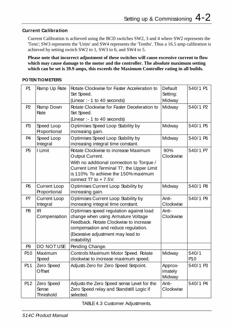
Current Calibration is achieved using the BCD switches SW2, 3 and 4 where SW2 represents the'Tens'; SW3 represents the 'Units' and SW4 represents the 'Tenths'. Thus a 16.5 amp calibration isachieved by setting switch SW2 to 1, SW3 to 6, and SW4 to 5.
Please note that incorrect adjustment of these switches will cause excessive current to flowwhich may cause damage to the motor and the controller. The absolute maximum settingwhich can be set is 39.9 amps, this exceeds the Maximum Controller rating in all builds.
POTENTIOMETERS
P1 Ramp Up Rate Rotate Clockwise for Faster Acceleration toSet Speed.(Linear :- 1 to 40 seconds)
DefaultSetting:Midway
540/1 P1
P2 Ramp DownRate
Rotate Clockwise for Faster Deceleration toSet Speed.(Linear :- 1 to 40 seconds)
Midway 540/1 P2
P3 Speed LoopProportional
Optimises Speed Loop Stability byincreasing gain.
Midway 540/1 P5
P4 Speed LoopIntegral
Optimises Speed Loop Stability byincreasing integral time constant.
Midway 540/1 P6
P5 I Limit Rotate Clockwise to increase MaximumOutput Current.With no additional connection to Torque /Current Limit Terminal T7, the Upper Limitis 110%. To achieve the 150% maximumconnect T7 to +7.5V.
90%Clockwise
540/1 P7
P6 Current LoopProportional
Optimises Current Loop Stability byincreasing gain.
Midway 540/1 P8
P7 Current LoopIntegral
Optimises Current Loop Stability byincreasing integral time constant.
Anti-Clockwise
540/1 P9
P8 IRCompensation
Optimises speed regulation against loadchange when using Armature VoltageFeedback. Rotate Clockwise to increasecompensation and reduce regulation.(Excessive adjustment may lead toinstability)
Anti-Clockwise
P9 DO NOT USE Pending Change.P10 Maximum
SpeedControls Maximum Motor Speed. Rotateclockwise to increase maximum speed.
Midway 540/1P10
P11 Zero SpeedOffset
Adjusts Zero for Zero Speed Setpoint. Approx-imatelyMidway
540/1 P3
P12 Zero SpeedSenseThreshold
Adjusts the Zero Speed sense Level for theZero Speed relay and Standstill Logic ifselected.
Anti-Clockwise
540/1 P4
TABLE 4.3 Customer Adjustments.

4-3 Setting up & Commissioning
514C Product Manual
BASIC SETTING-UP PROCEDURE
Preliminary Precautions
BEFORE ATTEMPTING TO CONNECT POWER:-
CONTROLLERCONTROLLERCONTROLLERCONTROLLER
Check:-
1. The Auxiliary Supply Voltage is correctly selected on the Power Board.
2. The Main Power Supply Voltage is within the operating range of the controller.
3. The Armature Voltage and current ratings are compatible with controller supplied.
4. The Field Voltage and current ratings are suitable.
5. All external wiring circuits are correct, i.e:- a) Auxiliary connectionsb) Power connectionsc) Control connectionsd) Motor connections
NOTE: Completely disconnect the controller before point to point checking with a buzzer orwhen checking insulation with a megger.
6. For damage to equipment.
7. For loose ends, clippings, drilling swarf etc., lodged in the drive or ancillary equipment.
MOTORMOTORMOTORMOTOR
1. Inspect the motor, in particular the commutator for any extraneous matter. If an air supply isavailable, it is recommended to blow over the commutator.
Check the brushes are properly seated and that the brush spring tension is adequate.
If possible check that the motor (and vent fan if fitted) can be turned freely by hand.
Preparation
MACHINEMACHINEMACHINEMACHINE
Check:-
1. That rotation of the motor in either direction will not cause damage.
2. That nobody else is working on another part of the equipment that will be affected bypowering up.
3. That other equipment will not be adversely affected by powering up.
CONTROLLERCONTROLLERCONTROLLERCONTROLLER
1. Prevent application of the main power supply by removal of the supply fuses.
2. Disconnect the load from the motor shaft if possible.
3. If there is any doubt as to the integrity of a particular installation, insert a high wattage resistor(i.e. fire bar elements) in series with the motor armature.
4. If it is possible to rotate the motor, and tachogenerator feedback is in use, check that forwardrotation results in positive tacho feedback, i.e. terminal 1 is positive with respect to terminal 8or 11.

Setting up & Commissioning 4-4
514C Product Manual
5. Check switch selection
SW1/1 ) Speed Range (see table 4.1)SW1/2 )SW1/3 Tachogenerator / VA (see switch options on page 4.1)SW1/4 Zero Speed / Zero Setpoint (see switch options on page 4.1)SW1/5 Current Meter OutputSW1/6 Use of Setpoint RampSW1/7 Standstill LogicSW1/8 Current Demand strategySW1/9 Contactor Drop Out on Over-CurrentSW1/10 Zero Setpoint source
6. SW2, 3 and 4 Check Current Calibration.
7. Check all pots are set thus:-
Potentiometers P4, P5, P6, P8, P10, P12 fully anticlockwise.(Potentiometer P5 will be set to 90% clockwise when the drive is unpacked).Potentiometers P1, P2 , P3 and P6 mid position.Potentiometer P11 should be left at the factory set position (approximately midway) until zerospeed adjustment is required.
8. Check auxiliary supply transformer tap is compatible with the auxiliary supply voltage.
9. Check external run contacts are open.
10. Check external set points are all zero.
Power-UpAlthough fairly general, the following assumes the system to be a simple speed control driveand motor.
1. When all the preceding steps are completed the auxiliary power supply can be connected toterminals A3 and A4, (but do not connect the L1 and L2 main power supply at this stage).Immediately check that the correct voltage appears between A3 and A4.
2. Now check:-
i) The drive condition indicators - these are 5 LED lamps at the top left corner of theproduct. The “Power-On” should be on.
ii) Check that the +24v (nominal) supply at terminal T24 (with respect to T8 or T11) isbetween 22 and 30 volts dc.
iii) If a Diagnostic Test Unit (5570) is available, check the ± 15v supplies on switchpositions 1 and 4.
iv) Check the + 10v supply rail:
Switch to diagnostic test point 2 or measure the voltage between terminals T14 (+10v)and T8 (0v).
v) Check the -10v supply rail:
Switch to diagnostic test point 3 or measure the voltage between terminals T16 (-10v)and T8 (0v).
Note:- If the supply voltages are incorrect check setting of Auxiliary Supply Selector Switch.
3. If a Diagnostic Test Unit is available, check that all other test point readings are as shown inDiagnostic Chart 3.

4-5 Setting up & Commissioning
514C Product Manual
4. Check that a speed demand signal is available. This will normally appear as an input to theSetpoint Ramp on terminal T13 (diagnostic test point 11).Additional setpoint inputs may also appear at:Positive trim, terminal T10 (diagnostic 12)
Negative trim, terminal T17 (diagnostic 13)
Note: The sum of the setpoint voltages appears at terminal T12 (diagnostic 15) as the TotalSetpoint voltage.
5. Check the polarity of the tachogenerator signal, if used, by rotating the motor shaft manually inthe “forward” direction (i.e., the direction which should correspond to a positive setpoint at T13):The voltage at terminal T1 (or T3) should go positive.
If armature voltage feedback is being used the polarity of the feedback signal is inherentlycorrect. It is however important to ensure that the speed scaling has been set correctly even inarmature voltage feedback mode.
6. Apply the ‘RUN’ signal to T5 and maintain.The main supply contactor (L1 and L2) should close.Remove the ‘RUN’ signal.The main supply contactor should open. If not disconnect all power supplies and check therun circuit and contactor wiring.
Note: The main contactor should NEVER be operated by any means other than the driveinternal contactor control circuit as shown in the basic wiring diagram.
WARNING!
DO NOT PROCEED FURTHER UNLESS THE RUN CIRCUIT ANDCONTACTOR OPERATE CORRECTLY.
7. Turn off all power supplies to the equipment and when the whole system is totally isolatedand safe, re-connect the Main L1 and L2 supply.
8. Turn on Auxiliary single phase supply.
9. Turn on Main L1 and L2 supply.
10. Turn the Speed Setpoints to zero so that the Total Setpoint voltage is zero (terminal T12,Diagnostic 15).
11. Check that the Main Current Limit preset (P5) is turned to zero (fully anti-clockwise).
12. Initiate “Drive Run” and immediately check that the correct field voltage appears betweenterminals F+ and F-. Note that this will be high voltage dc, so proceed with extreme caution.
Do not continue if this is not correct, but switch off all supplies and check Field Voltage iscompatible with supply.
Check that the motor ventilation fan, if fitted, is rotating in the correct direction. Check thedirection visually as the fan starts since a centrifugal fan may produce considerable air floweven when rotating in the wrong direction.
13. Check that LED 4 PLL Lock is illuminated. Refer to the Diagnostic section for explanation ofthe LED functions.
14. Check that the Standstill Logic is switched OFF (SW1/7).
NOTE:-
a) During the following stages (15 and 16) be ready to stop the drive immediately shouldthe motor overspeed.

Setting up & Commissioning 4-6
514C Product Manual
b) Before altering any connections make sure that all Auxiliary and Main power suppliesare totally isolated from the drive and equipment and that the motor is stationary.
15. Adjust the Speed Setpoint so that the Total Setpoint voltage is about 0.5 Volts (terminal T12,Diagnostic 15).
Note:- If the Ramped Speed Setpoint is being used with default ramp settings the totalsetpoint will take time to change.
Slowly increase the Main Current Limit setting (P5) up to about 20% FLC (i.e., not more that 1volt at Diagnostic test position 24). Since the Total Setpoint is set to 0.5v the motor speed shouldincrease to only 5% of full speed. If this speed is exceeded, than the tacho polarity is wrong ortacho scaling is incorrect, quickly turn the Main Current Limited (P5) to zero (anti-clockwise).
Initiate Stop and de-energise the controller.
If overspeeding occurred while using a tachogenerator for speed feedback correct wiring as follows:
Problem Action
a)
b)
Direction correct but overspeeding:
Direction incorrect and overspeeding:
Reverse tacho polarity only
Reverse field polarity only
When armature voltage feedback is used for speed feedback it is direction insensitive andoverspeeding due to incorrect feedback cannot occur, excess speed is probably due toincorrect feedback scaling, check setting of switches SW1 and SW2.
If the motor runs under control but in the wrong direction correct as follows either:-
a)
b)
Armature Control
Tachogenerator Control
Reverse Field polarity
Reverse Field and Tachogenerator Polarity
16. When the Main Current Limited (P5) set to about 20% FLC slowly increase the Total Setpointvoltage to +1 volt (terminal T12, Diagnostic 15). The motor should now run at about 10%Full Speed.
Note: When correctly connected and operating normally at constant speed the Speed Feedbackvoltage (Diagnostic 16) will be equal to the Total Setpoint voltage (Diagnostic 15) but is of theopposite polarity. Under these conditions the Speed Error voltage (Diagnostic 17) will be zero.If this condition cannot be achieved, the system is probably in current limit (this is likely at thisstage if the output load is coupled to the motor shaft). Increase the setting of the Main CurrentLimit (P5) slowly until the motor accelerates to set speed and the Speed Error signal falls to zero.
17. Adjust the Total Setpoint voltage to about -1v and check that the motor runs in control in thereverse direction.
18. Set the Speed Setpoint to zero and adjust the Speed Zero preset potentiometer (P11) forminimum shaft creep. (Alternatively the Speed Zero potentiometer may be used to adjust thebalance of maximum speed in forward and reverse directions).
19. Gradually increase the Speed Setpoint to maximum and check that the shaft speed isnominally correct. Adjust P10 to desired speed. Check that the armature voltage does notexceed rated value.
Note: If the load is connected to the motor it may be necessary to increase the Main CurrentLimit control (P5) setting to achieve full speed.
20. Reverse the Speed Setpoint and check the maximum reverse speed.
21. Set the Main Current Limit (P5) to maximum. If in doubt monitor Diagnostic 24 and set to 5vi.e., 100% current.

4-7 Setting up & Commissioning
514C Product Manual
RUNNING PERFORMANCE ADJUSTMENTS
GENERAL
If the controller is operating in tachogenerator mode the IR compensation potentiometer (P8)must be anti-clockwise.
The Proportional and Integral potentiometers (P3, P4, P6 P7) as preset by Eurotherm Driveswill provide stable and responsive performance under most load conditions. Thus ifinstability is observed it is important to first check the load and coupling:
If there is a cyclic variation of the armature current check the mechanical couplings to the load- this is a common cause of apparent instability in either the speed or motor current. If speedinstability is present check whether the repetition rate of the instability is related to themechanical revolution of the load - if it is then the instability frequency will vary with speed.This form of instability may be reduced by adjustment of the drive presets, but totalelimination of the problem may require improvement of the load characteristics.
Instability due to incorrect setting of the drive control parameters can occur and isrecognisable because its frequency will be independent of the motor speed. If this form ofinstability is present, or if the application demands that the drive is trimmed for optimumresponse, then the stability controls may be adjusted as follows. Note that while the speedstability and response may be improved without the use of a Diagnostic Unit or Oscilloscopeit is difficult to optimise the current response without such instrumentation. Consequently,the following procedure assumes that both instruments are available.
Current Loop Adjustment (P6 and P7)
1. With all power supplies disconnected, disconnect the field wires from terminals F+ and F-labelling each wire clearly so that it can later be reconnected with the correct polarity.Connect the Stall Override terminal T15 to +10v.
NOTE:
(i) It is now possible to operate the motor in a stalled condition. Great care must be takennot to damage the motor by overheating. If the motor is fitted with a force ventilationfan, arrange that it is connected and running during the test. In any case DO NOTremain in the stalled condition for long periods.
(ii) Although the field supply is disconnected the motor may still produce some torque dueto residual or compound field flux. It is essential therefore, to mechanically lock themotor shaft, or apply sufficient load to prevent rotation during the following procedure.
2. The optimum setting of the Current Proportional and Integral presets (P6 and P7) depends, tosome extent, on the setting of the Main Current Limit (P5). Thus P5 should be correctlyadjusted to suit the load, before adjustment of P6 and P7 is attempted.
3. When the Main Current Limit control is correctly set, proceed as follows:
Ensure that a step change can be applied to the speed setpoint path.
Connect the Diagnostic Unit to the Control printed circuit board. Connect the Oscilloscope tothe output sockets on the Diagnostic Unit and switch to Diagnostic 26. This provides accessto a safe, isolated signal representing the armature current waveform where ± 1.1v = ± 100%full load current.
4. Reconnect the supplies, switch on and RUN. Observe the armature current waveform whilechanging the polarity of the Current Demand signal (by varying the Speed Setpoint). With each

Setting up & Commissioning 4-8
514C Product Manual
change of Current Demand polarity the current should increase rapidly, but without overshootand then remain steady. If necessary adjust P6 and P7 slowly to obtain a Critically Dampedperformance, i.e., the fastest response possible without overshoot, as shown in Figure 3.
Figures 1 and 2 show typical armature current waveforms where P6 and P7 are incorrectly setand indicate the adjustment required to improve the drive performance to conform with that ofFigure 3.
In general, clockwise rotation of the presets will improve the speed of response, but rotatingthe controls too far will tend to introduce overshoot.
FIGURE 1.
Current Loop controls incorrectly set.ARMATURE CURRENT WAVEFORM:
Integral Time Constant too short -increase Current Loop Integral TimeConstant by rotating P7 anticlockwise.
FIGURE 2.
ARMATURE CURRENT WAVEFORM:Current Loop controls incorrectly set.Proportional Gain too low - increaseCurrent Loop Proportional Gain byrotating P6 clockwise.
FIGURE 3.
ARMATURE CURRENT WAVEFORM:Current Loop Response (P6 and P7)correctly adjusted.
5. When the Current Loop response adjustment is completed, switch off the drive and disconnectall supplies.
Reconnect the field wires to terminals F+ and F- ensuring that they are replaced in theiroriginal positions i.e., with correct polarity. Remove any mechanical devices previously usedto lock the motor shaft.
Speed Loop Adjustment (P3 and P4)
1. If the Speed Setpoint is applied via the setpoint ramp turn P1 and P2 fully clockwiseminimum ramp time. Set the Speed Setpoint to zero. Switch the Diagnostic Unit to position16 so that the Oscilloscope displays the scaled Tacho Feedback signal (± 2.7v = ± 100%).
2. Reconnect the supplies switch on andinitiate “Run”. Apply a small setchange (about 20%) to the SpeedSetpoint input and observe the speedresponse. If necessary adjust the SpeedProportional and Speed Integral presets(P3 and P4) gradually to obtain aCritically Damped performance, i.e.,the fastest response possible withoutovershoot, as shown in Figure 4, Curve(c). In general, clockwise rotation ofthe presets will improve the rate ofresponse, but advancing the controlstoo far will tend to introduce overshoot.The optimum setting of P3 and P4 willbe a compromise between the twoextremes shown in Curves (a) and (b),Figure 4.
(a) Under Damped
(b) Over Damped
(c) Critically Damped
X %
SPEEDFEEDBACK(Diagnostic 16)
X %
SPEEDSETPOINT(Diagnostic 15)
TIME
TIME
FIGURE 4. TYPICAL SPEED RESPONSE CURVES

5-1 Diagnostics and Fault Finding
514C Product Manual
Chapter 5 Diagnostics and Fault FindingDIAGNOSTIC LEDS
LED1 POWER ON Illuminated when the Auxiliary Supply is energised.
LED2 STALL TRIP Illuminated when the Controller has detected a Stall orCurrent Limit Condition for more than 60 seconds.
LED3 OVERCURRENT Illuminated when the Armature Current exceedsapproximately 3½ times Calibrated Current.
LED4 PLL LOCK Illuminated when the Main AC Supply is energisedand the Electronic Phase Lock Loop is Synchronised.
LED5 CURRENT LIMIT Illuminated when the Controller is in Current Limit andSpeed Control is lost, i.e. a stall condition, after 60seconds the controller will trip.
RAMP UP
RAMP DOWNSPEED PROPORTIONAL
CURRENT LIMIT
IR COMPENSATION
MAX SPEED CALIBRATION
ZERO SPEED ADJUSTZERO SPEED THRESHOLD
SPEED INTEGRAL
CURRENT PROPORTIONAL
CURRENT INTEGRAL
P1P2P3P4P5P6P7P8P9
P10P11P12
L2 STALL TRIPL1 POWER ON
L3 OVERCURRENT
L4 PLL LOCK
L5 CURRENT LIMIT
SW1
SW2 SW3 SW4
A1 A2 A3 A4A1 A2 A3 A4A1 A2 A3 A4A1 A2 A3 A4
EUROTHERMDRIVES
514C
CAUTION
CAUTION
AVERTISSEMENT
CAUTION
1
ON
1 2 3 4 5 6 7 8 9 10
FL1 FL2 F- F+ L2/N L1 A+ A-
Before Switching ON Refer to the Manual for Installation and Safety,Switch and Transformer Setting Information.
Risk of Electric Shock - More than One Disconnect Switch may be Requiredto De-energise the Equipment Before Servicing
Risque de decharge electrique. La coupure de plusieurs interrupteurs poutetre necessaire avant utilisation - voir le schema
Compatible with Type B RCD Protection Devices Only
DIAGNOSTIC LEDS

Diagnostics and Fault Finding 5-2
514C Product Manual
DRIVE TRIPS
When a fault occurs the drive will trip and display the cause of the trip on the indicator LEDsor on the diagnostic (test point 6) for the Thermistor/Microtherm Trip.
The Stall Trip (LED2 on) and the Thermistor/Microtherm Trip are reset by re-applying the runsignal to Terminal 5. The drive will then re-start. (It is necessary to remove then re-apply therun signal.)
An Overcurrent (LED3 on) is not reset by the Run signal re-application as this trip canindicate that a major fault has occurred. The overcurrent trip is reset by removing then re-applying the auxiliary supply. Remove the Run signal before removing the auxiliary supply.
Resetting the Stall Trip does not reset the drive’s internal timer that caused the trip. If thedrive is operated in current limit (LED5 illuminated) immediately after a Stall Trip the tripcould re-occur. This protects the drive and the motor from continuous overload operation.However, it is possible to prevent the stall trip by using the Stall Override (Terminal 15)
DIAGNOSTIC TEST POINT DESCRIPTIONS
TestNode
Description Condition Voltage
1 Internal +15V Supply Auxiliary Supply On +15V ±0.15V2 External +10V Supply Auxiliary Supply On +10V ±0.025V3 External -10V Supply Auxiliary Supply On -10V ±0.025V4 Internal -15V Supply Auxiliary Supply On -15V ±0.15V5 Drive Enable Enable +10V to +24V
Terminal T20 Inhibit 0V6 Motor Microtherm Normal +12V to +15V
/Thermistor Overtemperature 0V to 2V7 At Zero Setpoint At Zero Setpoint +13V±2V
Above Zero Setpoint 0V8 At Zero Speed At Zero Speed +13V±2V
Above Zero Speed 0V9 Run Run +24V±4V
Terminal T5 Inhibit 0V10 Health Healthy +24V±4V
Terminal T19 Unhealthy 0V11 Setpoint Ramp Input 100% Forward Speed +10V
Terminal T13 Zero Speed 0V100% Reverse Speed -10V
12 Positive Trim Setpoint 100% Forward Speed +10VTerminal T10 Zero Speed 0V
100% Reverse Speed -10V13 Inverted Setpoint Sum 100% Forward Speed -10V
Terminal T21 Zero Speed 0V100% Reverse Speed +10V
14 Negative Trim Setpoint 100% Forward Speed -10VTerminal T17 Zero Speed 0V
100% Reverse Speed +10V
5-3 Diagnostics and Fault Finding
514C Product Manual
TestNode
Description Condition Voltage
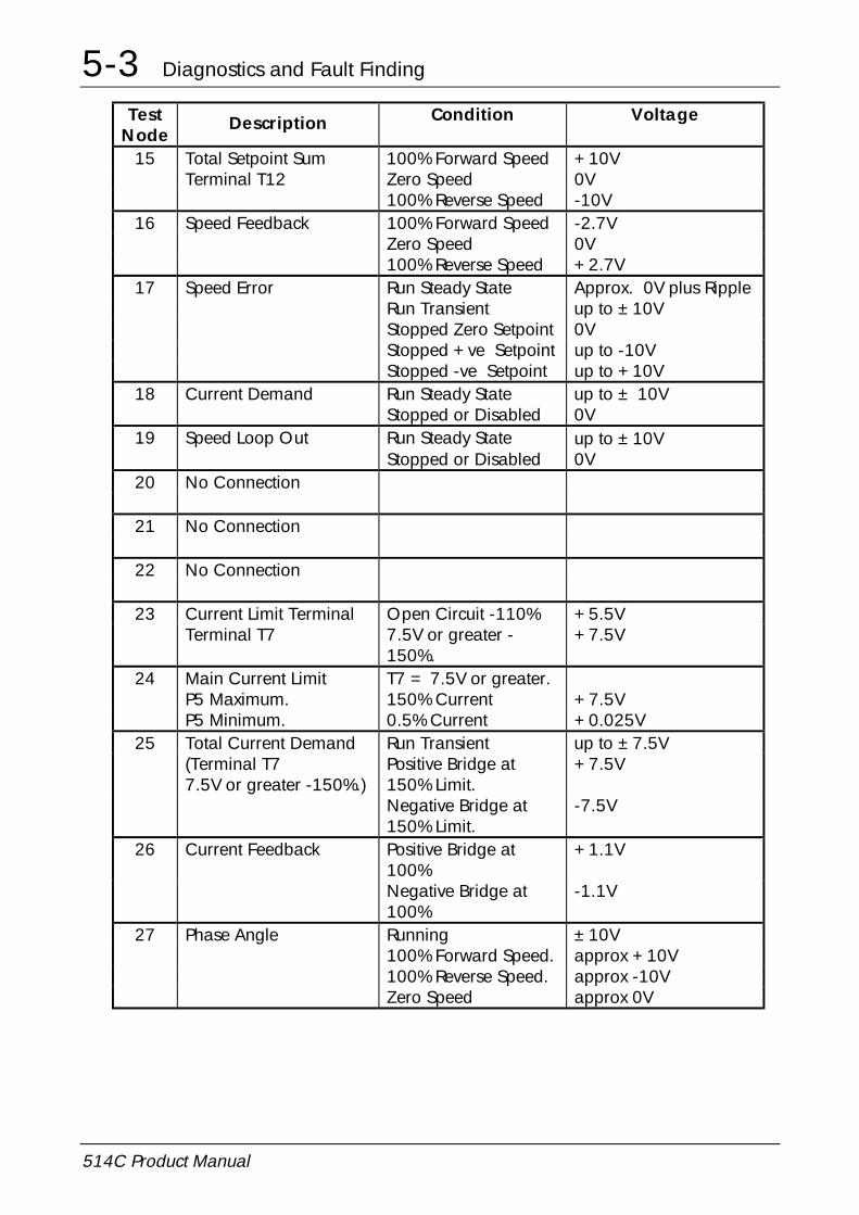
15 Total Setpoint Sum 100% Forward Speed +10VTerminal T12 Zero Speed 0V
100% Reverse Speed -10V16 Speed Feedback 100% Forward Speed -2.7V
Zero Speed 0V100% Reverse Speed +2.7V
17 Speed Error Run Steady State Approx. 0V plus RippleRun Transient up to ±10VStopped Zero Setpoint 0VStopped +ve Setpoint up to -10VStopped -ve Setpoint up to +10V
18 Current Demand Run Steady State up to ± 10VStopped or Disabled 0V
19 Speed Loop Out Run Steady State up to ± 10VStopped or Disabled 0V
20 No Connection
21 No Connection
22 No Connection
23 Current Limit Terminal Open Circuit -110% +5.5VTerminal T7 7.5V or greater -
150%.+7.5V
24 Main Current Limit T7 = 7.5V or greater.P5 Maximum. 150% Current +7.5VP5 Minimum. 0.5% Current +0.025V
25 Total Current Demand Run Transient up to ±7.5V(Terminal T77.5V or greater -150%.)
Positive Bridge at150% Limit.
+7.5V
Negative Bridge at150% Limit.
-7.5V
26 Current Feedback Positive Bridge at100%
+1.1V
Negative Bridge at100%
-1.1V
27 Phase Angle Running ±10V100% Forward Speed. approx +10V100% Reverse Speed. approx -10VZero Speed approx 0V

Diagnostics and Fault Finding 5-4
514C Product Manual
TROUBLESHOOTING
PROBLEM POSSIBLE CAUSE REMEDY"Power On" LED 1Not Illuminated
No Auxiliary SupplyAvailable.
Check Auxiliary Supply Availability. Isthe Supply Fuse fitted or the CircuitBreaker closed?
Auxiliary Supply Fuse. Supply fuse Blown. InvestigateContactor connections or TransformerTapping Switch position.
Incorrect Supply VoltageApplied to Controller.
Check that the Supply Voltage iscompatible with the TransformerTapping Switch position.
Illuminated but drivedoes not operate.
Incorrect Auxiliary SupplySwitch Setting.
Correct Auxiliary Supply Switch Setting.
Controller “Trips”Immediately afterDrive Run command.
Microtherm not wired. Connect Microtherm to terminals T22and T11 or if Microtherm not availablelink T22 to T11.
“PLL LOCK” LED 4not illuminated afterDrive Run command.
Main Power Supply notpresent.
1) Main Contactor not Energised.Check Run Command & Contactorwiring.
2) Is the Supply Fuse fitted or theCircuit Breaker closed?
Motor will not turnafter Drive Run
Enable Signal notpresent.
Check Control Circuit Wiring.
Command. No Speed Setpoint. Check Total Setpoint terminal T12.Check Setpoint Potentiometer & Wiring.If using the Setpoint Ramp Input T13check SW1/6 is OFF.
No Armature Current. Check P5 adjustment & ExternalCurrent Limit Potentiometer setting &wiring (if used).
No Field. Check Field AC Supply and Fieldconnections.
Motor Jammed. Free Obstruction.Motor Runs with“Current Limit”LED5 illuminated
Incorrect Current LimitSetting.
Check P5 setting.Check External Current limit setting &wiring if used.
and Stops after shortperiod with "Stall"
Incorrect CurrentCalibration.
Check Current Calibration SwitchesSW2, 3 & 4.
LED2 Illuminated Motor Jammed. Free Obstruction.Motor Runs andStops after short
Maximum ControllerOutput Exceeded
Check compatibility of Motor Voltageto Controller Output Voltage.
period with "Stall"LED2 Illuminated
Incorrect FeedbackVoltage Calibration
Check Feedback Voltage CalibrationSwitches SW1/1 & SW1/2. Note theseSwitches must be set for bothTachogenerator & Armature VoltageFeedback.
Faulty Tachogeneratorand/or Coupling.
Check Tachogenerator (use ArmatureVoltage Feedback Temporarily).

5-5 Diagnostics and Fault Finding
514C Product Manual
PROBLEM POSSIBLE CAUSE REMEDYMotor Runs but stopsafter a period with"Overcurrent Trip"LED 3 Illuminated.
Overcurrent. Check Motor wiring and Motor forearth faults.Check controller for Faulty ThyristorDevices.
Motor Runs but stopsafter a periodindicating Controller
Motor Overtemperaturetrip from MotorMicrotherm.
Check cooling Fan if used. Fan rotationmay be reversed giving airflow butinsufficient for adequate cooling.
Unhealthy. Check Cooling path.Motor runs at FullSpeed only
TachogeneratorFeedback. IncorrectTachogenerator Polarityor Open CircuitTachogenerator
Check Tachogenerator viability andconnectivity.Check Speed Feedback CalibrationSwitches.Check Max Speed CalibratePotentiometer P10.
Armature VoltageFeedback.
Check Speed Feedback CalibrationSwitches.Check Max Speed CalibratePotentiometer P10.
Open Circuit SpeedSetpoint Potentiometer
Check Terminal 13 or 10 asappropriate
Motor runs with ZeroSetpoint.
Zero Speed OffsetAdjustment
Adjust P11 to give Zero Speed
Motor Speedunstable at Constant
Stability Adjustment. See General Running performanceadjustments Chapter 4.
Speed Setpoint. Current Stability Adjust Current Loop StabilityPotentiometers P6 & P7.
Speed Stability Adjust Speed Loop StabilityPotentiometers P3 & P4.
IR Compensation. No IR compensation forTachogenerator Feedback. Reduce P8for Armature Voltage Feedback
Drive does notproduce required
Drive incorrectlycalibrated.
Set SW2, SW3, SW4 to correctcalibration current.
current. Current calibration setincorrectly.
The maximum current that the drivecan produce is its rated current.Setting the calibration above this cancause damage.Settings above 39.9Amps will causeerroneous calibration values.DO NOT CALIBRATE THE DRIVEABOVE RATED CURRENT.
Current Limit set wrongly. Check the current limit diagnostic 23and the main current limit diagnostic24. Adjust P5 and external currentlimit pot (if used).

Service and Repair 6-1
514C Product Manual
Chapter 6 Service and RepairThe product has no user serviceable parts and should be returned to Eurotherm Drives forrepair. The product should be returned in the original packaging if possible or else reasonablecare should be taken in the packing of the product to ensure that no transport damage beincurred.
Technical Support can be obtained by contacting Eurotherm Drives at the address given oryour local supplier.
DISPOSAL
This product contains materials which are consignable waste under the Special WasteRegulations 1996 which complies with the EC Hazardous Waste Directive – Directive91/689/EEC.
We recommend you dispose of the appropriate materials in accordance with the validenvironmental control laws. The following table shows which materials can be recycled andwhich have to be disposed of in a special way.
Matrial Recycle Disposal
metal yes no
plastics material yes no
printed circuit board no yes
The printed circuit board should be disposed of in one of two ways:
1. High temperature incineration (minimum temperature 1200oC) by an incineratorauthorised under parts A or B of the Environmental Protection Act.
2. Disposal in an engineered land fill site that is licensed to take aluminium electrolyticcapacitors. Do not dispose of in a land fill site set aside for domestic waste.
Packaging
During transport our products are protected by suitable packaging. This is entirelyenvironemntally compatible and should be taken for central disposal as secondary rawmaterial.

ISS. MODIFICATION ECN No. DATE DRAWN CHK'D
514C Product Manual.Sheet 1 filed in drawing office.
4 Added to Product Identification diagram“Auxiliary Supply Selector Switch”.Page 3-3 Added to Recommendations, “UnusedAnalogue ... interference”.Page 4-4 Added to Power-Up, v), “Note ...switch”.Page 4-6 Added to 15. “Note ... change.”Page 5-4 Added to Troubleshooting“Illuminated but Drive does not operate”. 12307 15.4.98 FEP GDR
5 Page 1-4 New CE EMC Declarations. 13908 15.1.01 FEP CMPages 1-8 changed Terminal Tightening Torquefrom 0.6 Nm to 0.45 and 4.5 lbf-in to 4.0.0.6 Nm to 0.5 and added (UL open-type).
13831
Page 1-11 Added “Overvoltage”. “Page 3-4 changed Terminal tightening TorqueControl settings from 0.6 to 0.45, 0.4 to 0.33,4.5 to 4.0 and Auxiliary settings from 0.6 to 0.5and 0.4 to 0.375.
“
Page 3-5 Re-written for UL CompliancePage 6-1 Added Disposal information.
“
Address list added to back cover. 13164
FIRST USED ON MODIFICATION RECORD
514C Product Manual
EUROTHERM DRIVES
DRAWING NUMBER
ZZ463296
SHT. 2
OF 2