Embed Size (px)
Citation preview

SJG Series Stationary Hydraulic Lift Table
Instruction
PT. ENERGI KHARISMA ABADI
Add:Raya Waru No. 38, Kedungrejo, Sidoarjo, 61256 Surabaya, Indonesia.
Tel: +62 31 855 5579 Fax: +62 31 853 1117
http://www.newleadeng.com

Preface
Thank you very much for your support to PT. ENERGI KHARISMA ABADI. In
order to operate in a safe and correct manner, and prolong its life-span, we
sincerely hope that you could read the instructions carefully before using the
equipment.
Our fixed scissors elevating work platform is divided into single fork type,
multistage scissor type and double fork type. It is widely used in factories, shops,
port, warehouse, mining, transportation and other industries. This equipment is for
stable lifting, safe, reliable, convenient, good quality.
Shall you facing problems upon operating this equipment, please refer to the
manual booklet for trouble-shooting purposes.

Safety Code
General safety rules
1. Know your machine
For your own safety, read this manual carefully. Being familiar with platform
applications and limitations associated with the platform, as well as potential
hazards.
2. Work area should be kept clean.
Clutter region as well as the work table can cause accidents.
3. Do not use under a dangerous environments
The Platform should be fixed in a sturdy designated pit, do not use in the wet or
rainy place, or be exposed to the rain. Keep the working area under good lighting
condition.
4. Unauthorized personnel do not get close to the lift table.
The operation maintenance platform for designated authorized professionals,
operating personnel in the work area must maintain a safe distance.
5. It must be clearly marked at the location of installation with warning signs "
without permission, shall not enter".
6. Do not force to operate the machine. Platform is designed at rated stroke speed,
under safety considerations.

7. Loading and unloading must be done carefully. The goods has to be placed at
center of platform as far as possible. Must not place rolling objects without taking
care, such as: lifting equipment like pallet truck, that might cause uneven lifting
due to moving about on the platform
8. Shall there be any sudden incident occur, such as pipe burst, shearing
deformation, the shaft pin loosening, etc. Immediate repair action must be carried
out, before continue using it.
9. Shall there be any power failure during operation where the platform is in lifting
position, loosen the "manual drop" switch anti-clock wise, and let the platform
lowered down slowly to the ground level, then tighten the "manual drop" switch
again at clock-wise to resume.
10. Do not press down button, while there are work carrying out at particular lifting
height.
11. Shall the equipment is not in operating, ensure the platform is lowered down
to the ground level, and shut off the power supply.
12. Do not carry out any maintenance job when the equipment is operating.
13. Before repair work carry out, shut down the power supply.
14. Study the usage of spare parts, before applying on the equipment.
15. Do not let the equipment operate unattended, and do not operate when it is
locked.

16. Platform safety device as shown below, the trip switch, safety contact edge
and explosion-proof valve. Safety device for permanent deformation after the
need to replace
1) The lifting switch is mounted based on manufacturer’s design. Shall you
need to make any adjustment, must be attended by authorized personnel.

2) Do not re-adjust the control system, as it has been tested and calibrated by
the manufacturer.
3) Explosion-proof valve is mounted and calibrated at the inlet of the cylinder,
do not re-adjust.
17. Warning signs as shown below
1) DANGER Electric Shock Risk
2) WARNING! SHEAR HAZARD.
3) Do not enter before supporting.

4) Do not stand, Sit or Climb on the Scissor Lift

2.1 Specification table
Parameter
Specification
SJG 3T-5M
Rated capacity(Kg) 3000
Lifting height (mm) 5000
Raised height (mm) 6050
Lower height (mm) 1050
Platform size (mm) 2500*2000
Elevating time (s) 60
Motor power (kw) 3.7
Total weight (kg) 2500
2.2 Machine Noise
Machinery was designed and constructed that risks resulting from the emission
of airborne noise are reduced to the lowest level taking accounting of technical
progress and the availability of means of reducing noise, in particular at source
DECLARED NOISE EMISSION VALUES in accordance with ISO 7960.
normal load
condition
full load
condition
Declared A-Weighted Emission
Sound Pressure Level , lpAd , in dB
re 20 μPa , at the operator’s
64 70
position.
Values determined according to specific test code ISO 3746.
The figures quoted are emission levels and are not necessarily safe work levels.
Whilst there a correlation between emission levels and exposure levels. This
cannot be used reliably to determine whether or not further precautions are
required. Factors that influence the actual level of exposure of work piece include
the duration of noise (i.e. The number of other adjacent machines).
2.3 Function of the Machine
2.3.1 Function of the machine
This machine can produce the following products
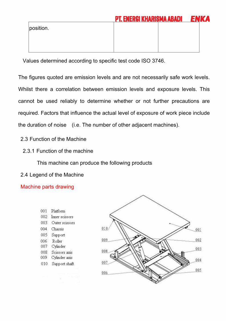
2.4 Legend of the Machine
Machine parts drawing

2.5 Dimension Drawing
2.6 machine size chart
a .Single fork structure
b. double fork structure.

3. Installation
3.1 Safety Rules for Machine Movement
3.1.1 When transports, please check the weight and the equipment hoisting
chart which the equipment specification provides, choose appropriately
hangs meets the tool to prevented damages the personnel or the
equipment.
3.1.2 On the equipment, do not push folds other heavy items.
3.1.3 At the site plan, choose the appropriate installation position, and
according to equipment gross weight with concrete placement
appropriate ground.
3.1.4 If the discovery equipment damage or lacks the spare part, please do not
operate.
3.1.5 Is reliable after the concrete ground, according to site plan, places the
adjustment horn in the ground, steadily lays aside the equipment on the
horn, through horn adjuster level.
3.2 Lifting the Machine/Drawing
3.2.1 Try to lift the equipment 20cm above the ground, observe its parallelism,
shall there be unbalance, do re- adjust the steel wire and lift again.
3.1.2 When hoisting, please strictly according to the hoisting chart position,
looks for the center of gravity spot, the level hoisting up before, after
does not allow, left, to be right not balanced hoists up, in order to the
equipment side turns, creates the personnel or the equipment damage.
3.1.3 After the hoisting up, lifting the machinery do not permit the person under
the machine, in order to avoid any endangers accident to occur.

Erection diagram
Platform lifting, according to the rope penetrates through the lifting ear
3.3 Selection of Location
Please uses under the below environmental condition,avoid mounting the
lifting table in a position where the noise of the table is magnified
Environmen
t
Environment
temperature
-10 --45 (does not ice up)
Environment
humidity
Below 90%RH(does not
congeal dew)
Storage -20 --65
temperature
Environment In room(non-corrosiveness
gas, flammable gas, oil mist
and so on)
Altitude above
sea level
Below elevation 1000m
Installation position
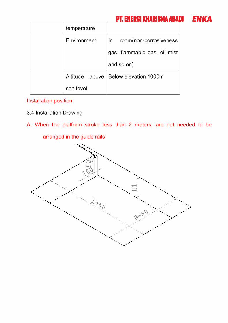
3.4 Installation Drawing
A. When the platform stroke less than 2 meters, are not needed to be
arranged in the guide rails

B, when the platform travel greater than 2 meters, to install guide
Install drawing

3.5 Installation and Leveling
The equipment need not be fixed with bolts. After the whole machine is already, adjust the regulating bolts under the mainframe and tighten the bolts between the automatically carrying bottle machine and rinsing bottle machine to ensure the same altitude and the machine frame level.

Installation and adjustment of level
The platform is mounted on a sturdy flat cement pit ( can bear the weight lifting
platform with 2 times the load and ). The platform into the ship direction to retain
30 ~ 35 mm distance to convenience goods goods.
The platform with four mounting plate, placing it in the machine at the bottom of
the four corners of the space position.
The machine is placed properly in the pit, adjust the level to a proper position.
The steps are as follows:
(1 ) in pit next to connect platform tubing and wire, can rise fall operation
platform
(2 ) lifting platform into the pit
(3 ) adjustment level, until the shipments into the direction parallel with the
ground
(4 ) steel plate can be placed in the machine at the bottom of the four corners
of the void position, from the middle to the underground drilling plate hole
diameter of 16 100 mm deep in the mounting hole
(5 ) sank into the expansion screws and lock nuts
(6 ) four steel plates and a base are welded together
(7 ) platform hydraulic station to be placed in an accessible location, and the
adjusting manual lowering valve, operating personnel can see platform down
state
(8 ) platform installation position of the vertical height for above 3 metres, the
client need to make the platform and the mounting position closely connected into
a whole, so as to avoid the danger caused by falling down the platform.

3.6 Power Supply Requirement
The equipment is supplied with 380V、50Hz AC of three phase and four wires, and
use 3×50mm2+1×25mm2cable, the grounding cable is connected with the
machine to ensure reliability
3.7 Connect Power Source Wires
(1) The machine has been factory pre-wired before shipment, according to the
specified voltage on the purchase order. However, before connecting the power
wires to your factory power supply, confirm again that the voltage of the
machine is the same as that of-your power supply.
(2) The power source connection points are located on the terminal plates inside
the electrical control box, and are marked "L1, L2, L3.". The machine should
be properly grounded to prevent the danger of electrical shock. The ground
wire connection point is marked "PE".
(3) After the power wires have been connected, make sure they are corrected to
the correct points as instructed below.
(4) The machine must be properly grounded to prevent possible injury from
electrical shock.
(5) All electrical connections should be performed by qualified electrical
personnel.

Note: the machine must be properly grounded
Ear thing mode for connecting the Yellow / green wire to the power supply and the
grounding end. In any case, power the machine connected to the power supply
must be determined before the machine has been grounded.
3.8 Check Connection of Power Wires
After connect all the power wires, please check the correctness of them
3.9 Pneumatic Supply Connection
The compressed air should be introduced to the automatically filling machine with pipes.
The compressed air must be clean and without water.
3.10 Oil Pressure Supply Connection
There are tap water and drain set near the equipment for cleaning the machine
and releasing waste water. Finished product water will be introduced to rinsing
pump and filling pump, at the same time drainage need to be prolonged to drain.
The pressure of the oil must maintain at ≤19MPa,and the temperature of the oil
must maintain at 50oC.

3.10 temporary storage
If machines in the delivery not immediately after installation and use, must be
machine stored in dry place.

4.1 staff operating location map
Personnel operating location map
Platform control box should be fixed at 1.2 m from the ground, and can not be
caught in the rain where air can not damp ; easy to operate.
Safety loading method and safety precautions:
Safety load method and safety precautions.
(1 ) platform mounted and fixed rear can use
(2 ) platform down to ground level at the lowest position will be rated load
cargo smooth handling to the platform, and try to make the goods weight on the
platform 's center position, the goods do not move
(3 ) checked the cargo cannot exceed the mesa, and not high
(4 ) determine correct, then press button will rise, cargo lift to rated height

4.2 Control Panel operation panel description
1)Checking before operation
a) Dustless uniform needed for the operator and no dust inside the booth
b) Whether there is enough fuel or leakage.
c) Checking the electrical and gas equipments.
d) Checking the power for control panel and whether there are some unusual
possibilities
2) Preparation for the work-piece to be sprayed
- Please strictly comply the following regulation in order to keep the
work-piece being sprayed inside the booth clean
- Do cleaning jobs well before work-piece enters the booth
- Keep grounding well in case of static electricity inside the booth
- Please use the special tools for dustless
- Please get rid of the dust and greasy from the work-piece after starting the
running for 5-15minutes

3) The description of the control pane
Platform operating panel.
4.3 Emergency Stop
Lifting platform for electric control box and an operating handle are respectively
provided with a red emergency stop button. On the platform during operation,
operation personnel needs observation platform operation, if the abnormal
phenomena, should immediately press the emergency stop button, anomalies
excluded, the emergency stop button to reset.

4.4 Operation Procedure
A, inching control operation:
The closed electric control box and the power switch ( in the installation of
equipment in former users have ).
The electric control box and then close the power switch Q, the power indicator
light HD light.
The hold up the green button is not loosened, table rise, rises to the position after
the rise of travel switch controls the automatic stop, and then release the button
up the end of the process. In the rising process may also be required to release
this button in the effective stroke of worktable in arbitrary height at the stop.
The hold down white button is loosen, table drop, fall in place after the release of
this button, workbench to stop the decline decline across the end of the process.
In the process of decline may also need to release this button in the effective
stroke of worktable in arbitrary height at the stop. Note: the rate of decline is
controllable. According to the body weight, adjust the rate of decline : the
clockwise direction regulating throttle valve slower rate, counterclockwise
adjustment throttle valve fall faster.
The work in process of sudden power failure, table static in the air, it must be
manually drop function will cargo fell to the lowest safe position. Methods : the
counterclockwise direction regulating pine" manual lowering valve" of the table
slowly lowered to the ground, then clockwise to tighten the" manual lowering
valve", in order to resume normal work after. Note: this circuit is provided with

under-voltage protection function, when the power supply power supply is
suddenly broken, total power circuit automatically disconnects power restoration
must be approved by the manual operation, the total power circuit can
automatically switch on, return to normal work.
The finished work, work cannot be suspended in the air or rises to the highest
position, must fall to the lowest position, and cut off the power.
B, the self-locking control operation:
The closed electric control box and the power switch ( in the installation of
equipment in former users have ).
The electric control box and then close the power switch Q, the power indicator
light HD light.
The press the desired floor up button then release circuit self-locking, work began
to rise, rise to the corresponding level of the upstream limit switch control is
automatically stopped. In the rising process can not be arbitrarily stop, unless the
emergency stop.
The press the desired floor down button immediately after release, circuit
self-locking, work began to decline, down to the corresponding level by the down
limit switch control is automatically stopped. In the process of falling can not
arbitrarily stop, unless the emergency stop. Note: this circuit is provided with

under-voltage protection function, when the power supply power supply is
suddenly broken, total power circuit automatically disconnects power restoration
must be approved by the manual operation, the total power circuit can
automatically switch on, return to normal work.
In different floors are a set of operating switch, its function and the control box
panel.
In the work process of sudden power failure, can use manual lowering function
will work table and the cargo dropped to its lowest level, to ensure safety. Method
of operating the same point control.
The finished work, work cannot be suspended in the air or rises to the highest
position, must fall to the lowest position, and cut off the power.

5 examples of maintenance and troubleshooting
5.1 maintenance:
The 1 rotating pin shaft, wheel, rail often keep the grease lubrication, each
part time lubrication ; ; check fastening pin shafts and nuts, washers, whether
there is loose, if there is tight.
2 new product a month replacement of hydraulic oil once, later replaced every
six months. Hydraulic oil general winter for the N32 number, summer for the N46
number. In general I designated the hydraulic oil as the Great Wall 68 #
wear-resistant circulating hydraulic oil. The user can replace the similar nature of
the hydraulic oil.
3 remain installed the pit position without hydronephrosis, each rail (upper and
lower, the vertical guide rail ) on no dust or other obstacles. Periodic removal
platform surrounding the waste / dust / grunge.
4 often check up limit switch, decline limit switch, safety switch and the
operating buttons are failure, there is the timely repair or replacement.
5 often check the tubing, cable is whether the deformation, hardening and
damage, leakage or short circuit condition; the pipe joint is loose, there is no oil or
oil leakage phenomenon, there is the timely repair or replacement.

6 each track and the guide wheel, the connecting pin shaft and the shaft sleeve
clearance is used for a long time to wear too much, if you replaced immediately
before use.
7 hydraulic tubing specifications for the diameter of 6 mm, 18 mm diameter,
nominal working pressure of 48MPa in failure cases need to be replaced : the
whole tubing from the interface removed, selected the same types of tubing cut
the same length, with good pipe joints, the pressure pipe machine pressure, then
loaded to the same set.
8 under the action of external force, the tubing at the interface may loosen the
oil spill, is not normal operation platform. If in the process of the use of oil spills,
the platform may rise speed slows or cannot lift, or will slow down. The operator
should safely in the case of timely tightening, or let the platform to a minimum
position for the repair processing. If the interface joint damage occurs, it may also
occur in the case of oil spills, requires replacement of the same type of parts.

Fault analysis and solution of 5.2 : ( lifting platform in repair needs in accordance
with EN 1570 Appendix C to test)
Fault
phenomeno
n
Reason Solve
The power
indicator
light does
not shine
1. No power
2. Power indicator don't close
3. The light broken
4. Fuse broken
5. Others
1.Check the line
2.Close the power indicator
3.Change
4.check the wire and change again
Push the lift
up can not
lift
1. Lift power broken
2. Indicator can not contact
3. Motor broken
4. Fuse broken
5. Manual lift down has problem
6. Wire broken
7. Pressure regulating valve
pressure too low
8. Pump problem
1.Change new one
2.Contact with the line again
3.Change the wire power line
4.Change
5.Check it and fix the button
6.Check and repair it
7.Adjust the pressure
8.Change or repair
1. Switch broken 1. Change
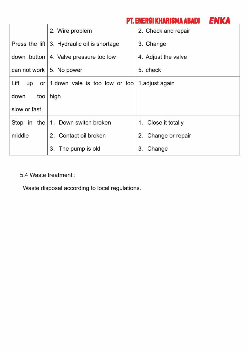
Press the lift
down button
can not work
2. Wire problem
3. Hydraulic oil is shortage
4. Valve pressure too low
5. No power
2. Check and repair
3. Change
4. Adjust the valve
5. check
Lift up or
down too
slow or fast
1.down vale is too low or too
high
1.adjust again
Stop in the
middle
1.Down switch broken
2.Contact oil broken
3.The pump is old
1.Close it totally
2.Change or repair
3.Change
5.4 Waste treatment :
Waste disposal according to local regulations.

6 Electrical System
6.1 electrical system safety rules
1 only after formal training and professional knowledge of the staff can be
electrical repair and troubleshooting.
2 do not modify or omit protection interlock device.
3 before starting the read and pay attention to the warning signs.
4 when troubleshooting to determine when to cut off power supply, the main
switch must be unlocked.
5 pay attention to wet areas, in order to prevent electric shock.
6 the power to any equipment, personnel must be clear.
7 do not open the electrical box, unless there is a check electrical equipment
needs.
8 do not modify the circuit, unless the manufacturer Qualification Authorization.
9 when the replacement of electrical parts, must first determine whether it meets
the specifications, including wire color code.
10 when in the operation of electrical apparatus when not wearing metal glasses,
such as necklaces. Also do not wear the rings, watches, bracelets.

English Edition
1 Only personnel who are properly trained and have adequate knowledge and
skill should undertake all electrical / electronic troubleshooting and repair.
2 Do not alter or bypass protective interlocks.
3 Before starting read and , observe all warning labels.
4 When trouble shooting make sure the power source has been disconnected
and main switch has been locked.
5 Take extra precautions in damp areas to protect you from accidental
grounding.
6 Before applying power to any equipment it must be established, without a
doubt, that all persons are clear.
7 Do not open the electrical control panel unless it is necessary to check the
electrical equipment.
8 Do not alter the electrical circuits unless authorized to do so by the
manufacturer.
9 When replacing electrical components, make sure they conform to the
manufacturer s specifications, including proper color coding.
10 Do not wear metal frame glasses , metallic necklaces or chains while working
on any electrical equipment . Also do not wear any ring, watch or bracelet while
operating electrical equipment.

6.2Electrical Drawing circuit diagram ( Figure)
Platform circuit diagram
7.1 Pneumatic/ Oil pressure circuit Drawing