Embed Size (px)
Citation preview

ENVEST ENVIRONMENTAL LTD. Innovation in Business Centre, GMIT, Westport Road, Castlebar, Co. Mayo. www.envest.ie Registered in Ireland (Company Reg. No: 517536 / Company Tax Reg. No.: 9841869R, Directors: M. Keegan, C. Staunton)
Ref: ENV-1367/CS/08 Date: 11th May 2015 Ms Elizabeth Leacy Administration Officer Office of Climate, Licensing and Resource Use Environmental Protection Agency Johnstown Castle Estate County Wexford Dear Elizabeth,
Re. Glenmore Biogas Ltd.: Reg. No. P1004-02 – Response to FI Letter
In response to your letter dated 5th May 2015, the following provides a response to the
queries raised.
FI dated 05/05/20152015 – Regulation 9 of SI 137 of 2013
Q1 Provide an amended drawing (Drawing No. Figure B1) showing the SuDS
drainage area within the red line boundary of the installation, as confirmed in
response to Question 13a of the Regulation 10 Notification dated 12th February
2015. [Regulation (9)(2)(g)]
R.1 Please find attached amended drawing (Figure B1) showing the SuDS drainage
area within the red line boundary of the installation.
Q.2 Outline the procedure to be followed in the event that a batch of digestate fails
the test against the quality standard including in situations where the digestate
is being stored off site. [Regulation (9)(2)(g)].
R.2 It is proposed to transfer stable digestate from the AD plant to the proposed
lagoon facility for temporary storage prior to end use proposals (application to
land as OF/SI on agricultural and forestry lands). The digestate will be tested
for conformance with an accepted and known quality standard at the AD plant
prior to being transported to the storage lagoon. Digestate for testing will be
dispensed from the secondary digester to a dedicated 25,000 litre batch
holding tank located within the feedstock reception building. From here a
sample will be taken and sent for analysis. Sampling of digestate will be
For
insp
ectio
n pur
pose
s only
.
Conse
nt of
copy
right
owne
r req
uired
for a
ny ot
her u
se.
EPA Export 21-05-2015:23:35:08

ENVEST ENVIRONMENTAL LTD. Innovation in Business Centre, GMIT, Westport Road, Castlebar, Co. Mayo. www.envest.ie Registered in Ireland (Company Reg. No: 517536 / Company Tax Reg. No.: 9841869R, Directors: M. Keegan, C. Staunton)
representative of the portion of production sampled (see attached flow
schematic and layout drawings [001 & 009] showing location of digestate
holding /testing tank). In addition continuous monitoring of conditions and
parameters will be undertaken in advance of dispensing digestate from the
secondary digester for testing /transfer to the storage lagoon. Forward
knowledge of parameters such volatile fatty acids (VFA) of digestate in the
system will give indicative results as to expected residual biogas potential
(RBP) of the digestate.
Treated waste that fails to meet the quality standard for digestate (i.e.
Maximum Respiration Activity, Pathogenic Organism Content Limits, Impurity
Content Limits and Organic Matter Content Limit) will either be recycled to the
process or treated as waste. Treated waste that fails to meet the criteria for
metal concentration limits will be treated as a waste and not recycled to the
process. Treated waste which fails to meet the quality standard and is sent
off-site for disposal at a waste licensed facility will be transported only by an
authorised waste contractor. A record of all non-conforming batches will be
kept and will be available for inspection.
In the event of a failure to meet the digestate quality standard, a review and
evaluation of feedstock and /or process changes relevant to the sampled batch
of material prior to the sampling date will be undertaken. Corrective actions
will be undertaken which will include re-sampling, recycling of material and
increase to the frequency of digestate batch testing until such time that
conditions /digestate is deemed to be stable and in compliance. Once
digestate is deemed to be compliant and the corrective actions have been
completed, the normal digestate monitoring programme will be reinstalled.
We also wish to inform you that planning permission was granted by Donegal County
Council on the 7th May to Glenmore Biogas Limited for development as set out under
planning permission ref 14/51399.
Yours sincerely,
Colm Staunton
Director For and on behalf of Envest Environmental Ltd.
For
insp
ectio
n pur
pose
s only
.
Conse
nt of
copy
right
owne
r req
uired
for a
ny ot
her u
se.
EPA Export 21-05-2015:23:35:08

ENVEST ENVIRONMENTAL LTD. Innovation in Business Centre, GMIT, Westport Road, Castlebar, Co. Mayo. www.envest.ie Registered in Ireland (Company Reg. No: 517536 / Company Tax Reg. No.: 9841869R, Directors: M. Keegan, C. Staunton)
Attachments
Amended Layout Drawing Showing Red Line Boundary (Ref. Figure B1)
Amended Site Layout Drawing (Ref. 001)
Amended Feedstock Building Layout Drawing (Ref. 009)
Amended Process Flow Schematic, v1.4
Revised Non Technical Summary
For
insp
ectio
n pur
pose
s only
.
Conse
nt of
copy
right
owne
r req
uired
for a
ny ot
her u
se.
EPA Export 21-05-2015:23:35:08

CO2 Building
Access Road
Reception Building
Control BuildingBiogas Purif ication & Bottling Plant
Pump House Building& Anaerobic Digestors
Flare Stack
CHP Engine
Reception Building OCU Stack
207800
207800
207900
207900
208000
208000
208100
208100
208200
208200
208300
208300
208400
208400
208500
208500
208600
208600
208700
208700
3956
00
3956
00
3957
00
3957
00
3958
00
3958
00
3959
00
3959
00
3960
00
3960
00
3961
00
3961
00
3962
00
3962
00
Client:Glenmore Biogas Ltd.
Project:Anaerobic Digestion, CHP Plant & Biogas Purification Plant.
Prepared by:Envest Environmental Ltd.www.envest.ie
Project Number:ENV-1367
Drawing Title / Scenario:Site Location Mapshowing Redline Boundary.
Drawing Number:Figure B1
Scale : 2,500:1 @ A3
07.05.15
For
insp
ectio
n pur
pose
s only
.
Conse
nt of
copy
right
owne
r req
uired
for a
ny ot
her u
se.
EPA Export 21-05-2015:23:35:08

Digester 2
Digester 1
Digester 4
Digester 3
Feed
Building
Control
Building
Pre Pit
CO2
Compression
Building
Compressor
Gas Purification
and Bottle Plant
Pump
House
Building
Flare
R
e
t
a
in
in
g
W
a
ll
S
t
r
u
c
t
u
r
e
R
e
t
a
i
n
i
n
g
W
a
l
l
S
t
r
u
c
t
u
r
e
R
e
t
a
i
n
i
n
g
W
a
l
l
S
t
r
u
c
t
u
r
e
Compressor
G
a
s
T
r
a
i
l
e
r
G
a
s
T
r
a
i
l
e
r
Concrete Access Road
W
e
i
g
h
B
r
i
d
g
e
Lorry Washdown Area
C
o
n
c
r
e
t
e
A
c
c
e
s
s
R
o
a
d
Surface water
overflow /
Washwater P.S.
1.0m high RC
Bund Wall
1.0m high RC
Bund Wall
1.0m high RC
Bund Wall
1.0m high RC
Bund Wall
1.0m high RC
Bund Wall
R
e
t
a
i
n
i
n
g
W
a
l
l
S
t
r
u
c
t
u
r
e
R
e
t
a
i
n
i
n
g
W
a
l
l
S
t
r
u
c
t
u
r
e
R
e
t
a
i
n
i
n
g
W
a
l
l
S
t
r
u
c
t
u
r
e
R
e
t
a
i
n
i
n
g
W
a
l
l
S
t
r
u
c
t
u
r
e
C
o
n
c
r
e
t
e
A
c
c
e
s
s
R
o
a
d
C
o
n
c
r
e
t
e
A
c
c
e
s
s
R
o
a
d
100m3
Washwater
Storage Tank
CHP Unit
132.708 m
133.000 m
133.000 m
133.000 m
133.000 m
133.145 m
135.000 m
133.174 m
130.242 m
123.500 m
123.500 m
123.500 m
124.500 m
123.549 m
123.500 m
123.500 m
123.500 m
123.500 m
123.500 m
123.500
123.500
124.500
128.547 m
127.300 m
125.010 m
Concrete Hardstanding
Concrete Hardstanding
C
o
n
c
r
e
t
e
H
a
r
d
s
t
a
n
d
i
n
g
Carbon Filter
and Stack for
Odour Control
Lorry Loadin Area
Digester Draindown/
Tankering Area
Bunded Fuel
Storage Tank
Area designated for
quatantine skip
11m3 covered and sealed
RO RO quarantine skip
Digestate
Quarantine Tank
Quarantine Tank
Liquid Feedstock
Tanks
Pasturisation Tanks
Holding / Isolation Tank
Date:
Scales:
Project Title:
Drawing Title:
Client/Architect:
Drawn by:
Checked by:
Approved by:
DRAWING
Status. Date. By. Check. Drawing Status Details. Appr.
Sheet Size:
Revision:Project Number:
Drawing Number:
Orig. Zone. Level. Type. Disc. Number.
E
Glenmore AD Plant
-
Site Layout
PRELIMINARY
WIS
SKL
LAM
141051
NOV 2014
1:200
A0
DC 00 ZZ GA C 001
Rev Date By Details Check Appr
- 25-7-14 SKL First issue - LAM
A 8-8-14 SKL Buildings Amended - LAM
B 19-8-14 SKL Prepit and CHP Building relocated - LAM
C 17-11-14 SKL Buildings relocated and Layout revised - LAM
D 18-11-14 SKL Odour Control Added - LAM
E 10-3-15 SKL Pipework, Drainage and Structures amended - LAM
1 : 200
Site Layout
1
Note:-
1. This drawing to be read in conjuction with all relevant
Engineers Drawings and documentation.
2. All levels in metres to Malin Ordnance Datum.
3. All dimensions in mm unless noted otherwise.
For
insp
ectio
n pur
pose
s only
.
Conse
nt of
copy
right
owne
r req
uired
for a
ny ot
her u
se.
EPA Export 21-05-2015:23:35:09
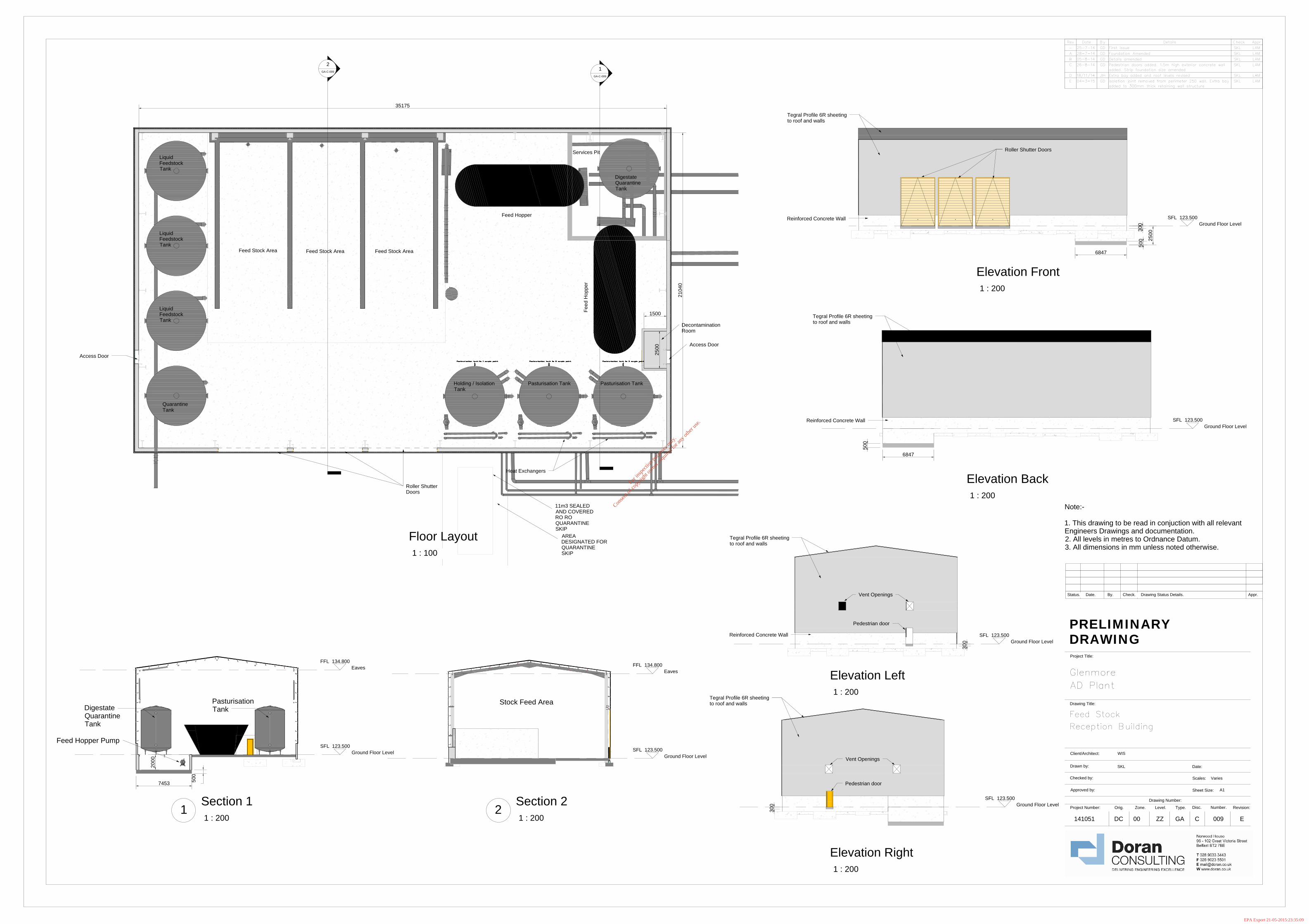
35175
21040
1
GA-C-009
2
GA-C-009
Feed Stock Area
Feed Stock Area
Feed Hopper
Feed H
opper
Pasturisation Tank Pasturisation Tank
Liquid
Feedstock
Tank
Liquid
Feedstock
Tank
Liquid
Feedstock
Tank
Heat Exchangers
Services Pit
Access Door
Access Door
Roller Shutter
Doors
Quarantine
Tank
Holding / Isolation
Tank
Feed Stock Area
Decontamination
Room
1500
2500
AREA
DESIGNATED FOR
QUARANTINE
SKIP
11m3 SEALED
AND COVERED
RO RO
QUARANTINE
SKIP
Digestate
Quarantine
Tank
SFL 123.500
Ground Floor Level
2500
500
300
6847
Tegral Profile 6R sheeting
to roof and walls
Reinforced Concrete Wall
Roller Shutter Doors
SFL 123.500
Ground Floor Level
50
0
6847
Tegral Profile 6R sheeting
to roof and walls
Reinforced Concrete Wall
SFL 123.500
Ground Floor Level
30
0
Vent Openings
Tegral Profile 6R sheeting
to roof and walls
Pedestrian door
Reinforced Concrete Wall
SFL 123.500
Ground Floor Level
300
Vent Openings
Tegral Profile 6R sheeting
to roof and walls
Pedestrian door
SFL 123.500
Ground Floor Level
FFL 134.800
Eaves
7453
50
0
20
00
Feed Hopper
Pasturisation
Tank
Feed Hopper Pump
Digestate
Quarantine
Tank
SFL 123.500
Ground Floor Level
FFL 134.800
Eaves
Stock Feed Area
Date:
Scales:
Revision:
Project Title:
Drawing Title:
Client/Architect:
Drawn by:
Checked by:
Approved by:
Project Number:
DRAWING
Drawing Number:
Sheet Size:
Status. Date. By. Check. Drawing Status Details. Appr.
Orig. Zone. Level. Type. Disc. Number.
E
Glenmore
AD Plant
Feed Stock
Reception Building
PRELIMINARY
WIS
SKL
141051
Varies
A1
DC 00 ZZ GA C 009
Rev Date By Details Check Appr
- 25-7-14 GD First issue SKL LAM
A 28-7-14 GD Foundation Amended SKL LAM
B 05-8-14 GD Details amended SKL LAM
C 26-8-14 GD Pedestrian doors added. 1.5m high exterior concrete wall
added. Strip foundation size amended
SKL LAM
D 18/11/14 JIH Extra bay added and roof levels revised SKL LAM
E 04-3-15 GD Isolation joint removed from perimeter 250 wall. Extra bay
added to 300mm thick retaining wall structure
SKL LAM
1 : 100
Floor Layout
1 : 200
Elevation Front
1 : 200
Elevation Back
1 : 200
Elevation Left
1 : 200
Elevation Right
1 : 200
Section 1
1
1 : 200
Section 2
2
Note:-
1. This drawing to be read in conjuction with all relevant
Engineers Drawings and documentation.
2. All levels in metres to Ordnance Datum.
3. All dimensions in mm unless noted otherwise.
For
insp
ectio
n pur
pose
s only
.
Conse
nt of
copy
right
owne
r req
uired
for a
ny ot
her u
se.
EPA Export 21-05-2015:23:35:09

For
insp
ectio
n pur
pose
s only
.
Conse
nt of
copy
right
owne
r req
uired
for a
ny ot
her u
se.
EPA Export 21-05-2015:23:35:09

Glenmore Biogas Ltd Attachment A
ENV-1367 (May 2015) A-1
Attachment A
Non-Technical Summary
(May 2015)
For
insp
ectio
n pur
pose
s only
.
Conse
nt of
copy
right
owne
r req
uired
for a
ny ot
her u
se.
EPA Export 21-05-2015:23:35:09

Glenmore Biogas Ltd Attachment A
ENV-1367 (May 2015) A-2
Table of Contents 1 GENERAL .......................................................................................... 3
2 PROPOSED SITE LOCATION ................................................................. 3
3 MANAGEMENT OF THE INSTALLATION ................................................... 4
4 INFRASTRUCTURE AND OPERATION ...................................................... 5
5 EMISSIONS AND IMPACT ON THE ENVIRONMENT .................................. 14
5.1 Atmospheric ........................................................................................... 14 5.2 Surface Waters ....................................................................................... 14 5.3 Sewer .................................................................................................... 14 5.4 Ground .................................................................................................. 14 5.5 Noise ..................................................................................................... 14
6 CONTROL AND MONITORING ............................................................. 15
7 RESOURCE USE AND ENERGY EFFICIENCY ........................................... 15
8 ACCIDENT PREVENTION AND EMERGENCY RESPONSE ........................... 16
9 REMEDIATION, DECOMMISSIONING, RESTORATION AND AFTERCARE ...... 17
For
insp
ectio
n pur
pose
s only
.
Conse
nt of
copy
right
owne
r req
uired
for a
ny ot
her u
se.
EPA Export 21-05-2015:23:35:09

Glenmore Biogas Ltd Attachment A
ENV-1367 (May 2015) A-3
1 GENERAL
Glemore Biogas Limited (formerly Glenmore Estate Aghaveagh NW Ltd.) was granted
planning permission (Ref. 13/51569) in July 2014 to construct a commercial centralised
anaerobic digester for the production of renewable energy and fertiliser. The
development will involve the construction of four primary digesters with collection
domes, a co-joining pump room and other structures associated with the operation of an
anaerobic digester system including the following: feedstock reception building, feed
hoppers, pre pit, CHP building, gas compression & carbon dioxide compression building,
flare and biogas purification and bottling unit.
A subsequent application (Ref. 14/51399) for planning permission and retention planning
was granted permission in May 2015 by the planning authority. .
The primary products generated at the site are biogas and digestate. The biogas will be
captured, cleaned and bottled and sold on for use as a bio-fuel and /or used to combust
in the on-site CHP to produce electricity and heat. It is expected that no more than 20
tonnes of biogas will be stored on the site at any one time (<7.5tonnes purified biogas -
biomethane). Carbon dioxide will also be recovered from the biogas and sold to the food
industry. The proposal will also produce up to 90,000 tpa of digestate which will be used
for fertiliser on agricultural and forestry lands.
2 PROPOSED SITE LOCATION
The proposed AD plant will be located on 0.72 hectares located within the south-western
area of lands known as the Glenmore Estate. The site is situated in the townland of
Aghaveagh which is situated along the River Finn half way between Donegal town and
Letterkenny, approximately 30km from each. The site is also approximately 30km west
of Strabane in the north of Ireland. The twin towns of Ballybofey and Stranorlar are
nearest to the proposal site approximately 6km to the east. The proposal site is located
a short distance from the R252 Glenfin Road west of Ballybofey. The R252 is a rural road
that connects the N56 in western Donegal to the N13/15 corridor in the east of the
County (Donegal Town to Letterkenny). The surrounding area of Aghaveagh is primarily
rural and agricultural. Small-scale farms and rural dwellings are most common with
some large-scale farming operations also present throughout the Finn Valley.
The site slopes downwards from south to north and away from the point of access.
Access to the site is via an existing laneway through the Estate from the R253 road. A
portion of the R253 road between the entrance to the estate and the R253’s junction
with the R252 Glenfin Road has been included within the site boundary because two
For
insp
ectio
n pur
pose
s only
.
Conse
nt of
copy
right
owne
r req
uired
for a
ny ot
her u
se.
EPA Export 21-05-2015:23:35:09

Glenmore Biogas Ltd Attachment A
ENV-1367 (May 2015) A-4
passing bays and minor alteration of road levels are proposed to facilitate the proposed
development.
The proposed site layout is shown on engineering drawing 141051-DC-00-ZZ-GA-C-001.
The site is accessed from the R253 road via a laneway through Glenmore Estate
3 MANAGEMENT OF THE INSTALLATION
Glenmore Biogas Ltd will have the ultimate responsibility for health, safety and
environmental issues relating to the operation of the facility. A suitably qualified and
technically competent Operations and Maintenance (O&M) Contractor, with previous
experience operating and maintaining power plants will be contracted by Glenmore
Biogas Ltd. The O&M Contractor will have responsibility for the day to day operation and
maintenance of the plant as well as environmental monitoring and reporting. The
contract between the Operator and the O&M Contractor will specify health and safety
and environmental obligations and responsibilities.
The plant manager will report directly to Glenmore Biogas Ltd. Site specific management
systems and operating procedures will be developed. The systems and procedures will
be continuously reviewed and developed by the operator and O&M contractor in
accordance with the principles of continuous improvement. The Plant Manager will be
directly responsible for the implementation of the Operators Health and Safety; all other
site personnel will have varying degrees of responsibility for their implementation.
Operations will be carried out in accordance with legislative requirements and the
conditions of the IE Licence and Planning Permission.
All personnel will be technically competent and suitably qualified to undertake their
assigned tasks. Training records will be maintained on site, available for inspection.
Personnel with responsibilities for operations, maintenance, health and safety and the
environment will receive task specific technical training, as required. A training needs
programme and matrix will be developed and updated on a regular basis. The
programme will take account of any incidents, amendments to site licence conditions,
changes to legislation, operations, operating procedures, emergency response and best
practice guidelines.
A site specific EMS will be developed and implemented for the facility in accordance with
ISO14001:2004 in due course. The EMS will provide the framework for environmental
management, ongoing assessment of environmental performance and continual
improvement at the power plant. The implementation of the EMS will include regular
For
insp
ectio
n pur
pose
s only
.
Conse
nt of
copy
right
owne
r req
uired
for a
ny ot
her u
se.
EPA Export 21-05-2015:23:35:09

Glenmore Biogas Ltd Attachment A
ENV-1367 (May 2015) A-5
cross-functional management reviews and will be subject to both internal and external
audits.
4 INFRASTRUCTURE AND OPERATION
The digestion system is a Continuously Stirred Tank Reactor (CSTR) type plant and will
be semi continuously fed with consistent pasteurised feedstock. Digested material will
be removed in batches representing a proportion of the total digester content.
Associated engineering drawings, civil and structural, are attached to Appendix D. Table
1 lists the main components of the facility and associated details.
Table 1 Details of the Proposed Facility Components
Item Details Weighbridge 1 no. at secured site entrance Feedstock Reception Building 1 no. for reception of all wastes Quarantine Area 1 no. beside feedstock reception building (sealed skip) Feedstock Bays 3 no. within feedstock reception building Pasteurisation Tanks and Heat Exchangers
2 no. within feedstock reception building (50m3 each)
Holding Tank 1 no. within feedstock reception building. To facilitate microbial testing /verification
Liquid Feed Tank 3 no. within feedstock reception building within delivery connection on western (front) side of building
Feed Hoppers 2 no. within feedstock reception building Digestate batch holding tank 1 no. within feedstock reception building Services Pit 1 no. within feedstock reception building containing
quickmix unit and macerator Pre-Pit 1 no. of 190m3 capacity Pump House Building 1 no. located between digestion tanks. Contains
delivery pipework, pasteurisation pumps and heat exchangers
Digestion Tanks 2 no. Primary and 2 no. Secondary
4 no. of 3,886m3 capacity each
Containerised CHP 1 x combined heat and power (CHP) containerised unit Gas Purification and Bottling Plant and Carbon Dioxide Compression Building
Containing; • Buildings • Containerised compressors (2 no.) • Storage tanks (2 no.) • CApureTM system & associated plant • Cooling tower (1 no.) • Truck filling point • Gas trailer areas (2 no.)
Control Building 1 no. containing; • Electrical substation areas containing bunded
electrical transformers • Welfare facilities – toilet and shower • Canteen • Storage room – bunded chemicals • Generator room • Panel room • SCADA /Control room
For
insp
ectio
n pur
pose
s only
.
Conse
nt of
copy
right
owne
r req
uired
for a
ny ot
her u
se.
EPA Export 21-05-2015:23:35:09

Glenmore Biogas Ltd Attachment A
ENV-1367 (May 2015) A-6
Item Details • Laboratory • 17.5m height stack (from ground level)
Gas Flare 1 no. for emergency use at 17.5m above ground level Odour Control System 1 no. on the feedstock reception building. Odorous
gases from the feedstock reception building areas will be extracted by fans and discharged into the impregnated carbon filter (ICF). From the outlet of the ICF the treated gas is finally discharged to atmosphere via an exhaust stack mounted directly on the carbon filter. The stack will be 17.5m above ground level (4.5m above roof of the tallest building on site)
Vehicle Wash Down Area 1 no. outdoor area -steam clean wash Process Drainage Recovering and containing contaminated waters and
effluents from process areas (e.g. CHP) Storm Water Drainage Separate isolated storm drainage system to manage
stormwater from non-risk areas to be designed in consideration of SuDS
Lighting Fencing and Security Gates
Along roads and around site perimeter
A description of the main items of plant and infrastructure proposed is as follows:
Weighbridge A weighbridge will be installed at the site entrance to provide for recording of material
inputs and outputs. This is important for both regulatory compliance and to effectively
manage the operation.
Waste (feedstock) Reception Building A reception building for the solid feedstock will be installed to receive the feedstock,
check the quality of feedstock, pre-treat the feedstock and process it through the plant.
The structural design of the waste reception building will be conventional structural steel
supported on reinforced concrete foundations. Steel columns will be fire protected as
necessary to comply with the building regulations. A 1.5m high reinforced concrete wall
will form external walls area (excluding openings) Tegral 6R sheeting used to sheet
remaining walls areas and roof area. Three (3 no.) fast acting roller shutter doors will be
provided for access and egress by delivery and other vehicles on the western side of the
building. Pedestrian access doors are also provided on the southern and northern sides
of the building.
A feedstock acceptance agreement will be completed by both the plant operator and the
feedstock supplier and the feedstock acceptance agreement will be kept on file for each
supplier of feedstock, both ABP and non-ABP, to the plant. The plant will follow a first-in
first-out (FIFO) procedure whereby older deliveries of waste are removed before newer
waste has been deposited for use.
For
insp
ectio
n pur
pose
s only
.
Conse
nt of
copy
right
owne
r req
uired
for a
ny ot
her u
se.
EPA Export 21-05-2015:23:35:09

Glenmore Biogas Ltd Attachment A
ENV-1367 (May 2015) A-7
It is not proposed to source or accept wastes containing packaging and other such
contaminants. Therefore there will be no requirement for screening for plastics and
other unsuitable materials.
The reception of waste feedstock will be carried out in an enclosed building which will be
kept under negative air pressure; this along with automatic door management and the
use of an air curtain, will significantly reduce the likelihood of fugitive emissions,
including noise, dust and odour. Exhaust air from the reception hall will be treated prior
to discharge to atmosphere. The reception building will provide adequate space to allow
control over waste delivery in order to minimise the amount of time that feedstock is
stockpiled before being processed.
The operating areas for unloading, preparing and processing feedstock will be
undertaken on an impermeable paved surface (i.e. to prevent the transmission of liquids
beyond the pavement surface) designed to the relevant British Standard. The surface
will be designed to be suitable to accommodate all of the static and dynamic loads
imposed by the vehicles, stored materials, machinery and process plant within the
proposed facility. The design, construction and maintenance of the pavement surface
will accommodate movements, reversing and tipping of vehicles, the use of unloading
areas for storage of waste, the use of mechanical shovels on the floor to move waste,
water containing contaminants dripping from vehicles and the washing down of the floor
for cleaning purposes. Feedstock unloading and preparation areas will be finished with a
proprietary finish to provide sufficient resistance to chemicals and abrasion for the stated
design life. The surface will have appropriate skid resistance and be suitable for
pressure jet washing.
Cleaning and wash down will be collected into gullies which will drain to the pre-pit for
use within the process. The self-contained drainage system within the reception building
will prevent any spillage entering the storage systems or escaping off-site. A vehicle
wash down area including wheel-wash facilities is located to the south of the reception
building for washing and disinfecting (steam wash) delivery vehicles on exit from the
reception hall. The provision of water and steam will be used to allow for cleaning of
vehicles and other transport equipment following delivery.
The air extraction system on the reception will be designed to ensure three (3 no.) air
changes per hour equivalent to 13,488m3/h based on the volume of the building. The
system will be designed to allow higher numbers of air changes within the building where
there is possibility of higher or more acute odour release; e.g. the system will be capable
of ramping up to 43,200m3/h when a roller shutter door is open. Any air movement will
For
insp
ectio
n pur
pose
s only
.
Conse
nt of
copy
right
owne
r req
uired
for a
ny ot
her u
se.
EPA Export 21-05-2015:23:35:09
Glenmore Biogas Ltd Attachment A
ENV-1367 (May 2015) A-8
be controlled to ensure air flows are from low odour areas to high odour areas. A
proposed stack height of 17.5m (4.5m above the highest roof level) is proposed which
will be mounted onto a carbon bed to abate odours from the waste reception building.
The reception area must be designed appropriately for the properties of the anticipated
feedstock inputs and it includes sufficient space and flexibility to manage changes in the
volume and properties of feedstock and vehicles that could occur over the lifespan of the
facility.
Three feedstock bays (4.55m wide) are included within the reception building where
feedstock deliveries are required to be offloaded for inspection and acceptance sampling
prior to pre-treatment. These bays will be managed to ensure waste is not stored for
more than 5 days and will be cleaned weekly. Should the inspection or analysis indicate
that the wastes fail to meet the acceptance criteria, then such loads will be stored in a
dedicated quarantine area within the reception building and dealt with appropriately.
Liquid feed-stocks will be received into three fully enclosed tanks within the reception
building by means of closed pipes. The liquid waste will be delivered via closed pipework
to the to the pasteurisation units from here.
Manure produced from the five adjoining cattle sheds will be transported by pipeline
from the below ground storage tanks beneath the sheds to the plant in order to avoid
disease risks associated with vehicles returning from the plant to the farm.
At the waste reception stage, the feedstock material will remain in storage for the least
time possible. The operator will empty the bunkers periodically (at least once a week) to
prevent a build-up of older waste in the bunker. This is because a high proportion of
waste is putrescible and will degrade aerobically and depending on the depth,
anaerobically, generating odour and leachate.
Two pasteurisation tanks (50m3) will be provided within the reception building.
Pasteurisation (pre digestion) will be carried out on all waste materials being processed
by the facility. An application for Stage 1 Approval of a Type 1 plant from the
Department of Agriculture Food and the Marine is currently being prepared.
The plant will be equipped with e.g. macerators capable of reducing the particle size of
the feedstock to the required size (<12mm) prior to entering the pasteurisation unit.
Batches of feedstock will be pasteurised at 70oC for 60 minutes.
The pasteurisation units will be equipped with sufficient temperature probes to provide
evidence that all the material is kept above the minimum temperature for the required
For
insp
ectio
n pur
pose
s only
.
Conse
nt of
copy
right
owne
r req
uired
for a
ny ot
her u
se.
EPA Export 21-05-2015:23:35:09

Glenmore Biogas Ltd Attachment A
ENV-1367 (May 2015) A-9
period of time. The plant will be equipped with recording equipment that will allow a
live, real-time thermograph to be produced from the temperature probe readings. The
probes, recording system and the thermographs produced will be tamperproof.
Pre Pit Process effluents generated at the site will be collected and discharged to a pre-pit
(190m3 capacity) prior to being pumped and processed within the waste reception
building and AD process. The pre-pit will receive process effluent collected by internal
drains (e.g. within the reception building and pump house building) and drainage from
external risk areas; i.e. external areas that have the potential for causing contamination
of surface drain water will be separated from the overall surface water drainage and
discharged to the enclosed pre-pit.
Digesters Four (4 no.) primary digesters all with a 27.6m diameter and capacity of 3,886m3 will be
installed at the site. The total capacity of the digester tanks is of 15,544m3. Following
the pasteurisation process, feedstock will be fed to the digesters where it will be retained
for about 63 days. This is sufficient time for it to digest and for as much gas as possible
to be extracted in order to maximise the revenue stream. The outputs from the
digestion phase are digestate and gas. It is proposed that the treated digestate from the
facility will be transported off-site to an approved Department of Agriculture Food and
Marine (DAFM) nearby storage facility. Biogas generated will be purified on site and
used in the bottling plant and the combined heat and power (CHP) plant to produce heat
and electricity for house load (the excess will be fed back to the electricity grid). It is
proposed that purified bottled biogas will be transported off site for utilisation in gas
engines on industrial sites.
Gas Flare A gas flare stack will be installed near the southern boundary of the site. The flare will
only be required in exceptional /emergency circumstances; e.g. when excess biogas
cannot be utilised by the CHP plant or the bottling plant.
Gas Purification and Bottling Plant Biogas Treatment will primarily consists of the following processes
• Dewatering;
• Removal of H2S (potentially corrosive to engines);
• Removal of oxygen and nitrogen (where present);
• Removal of ammonia;
• Removal of siloxanes (if treating Sewage Sludge) ;
• Removal of particulates; and
For
insp
ectio
n pur
pose
s only
.
Conse
nt of
copy
right
owne
r req
uired
for a
ny ot
her u
se.
EPA Export 21-05-2015:23:35:09
Glenmore Biogas Ltd Attachment A
ENV-1367 (May 2015) A-10
• Removal of CO2 (for upgrading to biomethane).
• Gas bottling
The techniques used in biogas treatment to remove these different elements are outlined
below
• Dewatering
Biogas leaving the digester is saturated with water and this may condense in gas
pipelines. The condensate will be contaminated and may cause corrosion. It is important
that wet gas transmission pipes and storage vessels can be drained to prevent them
from becoming flooded with condensate. Water removal plant and traps /taps will be
provided.
• Desulphurisation
The main sulphur compound in biogas is hydrogen sulphide (H2S). H2S is formed during
microbial reduction of sulphur containing compounds (sulphates, peptides, amino acids).
It is reactive with most metals and the reactivity is enhanced by concentration and
pressure, the presence of water and elevated temperatures.
H2S can cause corrosion problems in gas engines. Hydrogen sulphide has an energy
value and burns readily. When combusted, it forms SO2 leading to acidic conditions in
the presence of moisture formed when methane is burned. The presence of H2S in the
gas may also result in more frequent oil changes being required. Gas engine
manufacturers set limits on H2S tolerances (typically below 500 ppm).
H2S concentrations in the biogas can be decreased by precipitation in the digester or by
treating the gas either as a stand-alone treatment or as part of carbon dioxide removal.
At the Glenmore Biogas plant, desulphurisation will be undertaken by absorbing H2S on
inner surfaces of engineered activated carbon with defined pore sizes. The addition of
oxygen (in the presence of water) oxidises H2S to elemental sulphur that binds to the
surface. Activated carbon is either impregnated or doped with permanganate or
potassium iodide (KI), potassium carbonate, or zinc oxide (ZnO) as catalysers. Due to
limits on oxygen levels in biomethane, oxidisation of sulphur is not a suitable technique
where the gas is intended for grid injection or use as vehicle fuel. Use of KI-doped
carbon or permanganate impregnated carbon is used to effect oxidation without the
need for oxygen. ZnO impregnated carbon is expensive but extremely efficient. H2S
concentrations of less than 1 ppm can be achieved.
• Oxygen and Nitrogen
For
insp
ectio
n pur
pose
s only
.
Conse
nt of
copy
right
owne
r req
uired
for a
ny ot
her u
se.
EPA Export 21-05-2015:23:35:09
Glenmore Biogas Ltd Attachment A
ENV-1367 (May 2015) A-11
Oxygen is not normally present in biogas as it will be consumed by facultative aerobic
microorganisms in the digester. If air is present in the digester then nitrogen will also be
present in biogas. Oxygen and nitrogen can be removed with activated carbon,
molecular sieves or membranes.
These gases will be removed to some extent in a desulphurisation process or in some
upgrading techniques. Both gases are difficult (expensive) to remove, and their presence
should be avoided if the gas is to be upgraded. The presence of oxygen and nitrogen is
less of a concern if the gas is used for CHP or boilers as air is added to the gas during
the combustion process.
• Ammonia
Levels of ammonia present in biogas depend on the digester substrate composition and
pH within the digester. High concentrations of ammonia are a problem for gas engines,
and are often limited by manufacturers (typically up to 100 mg Nm-3). The combustion of
ammonia leads to the formation of nitrous oxide (NOx) in the exhaust. Ammonia is
usually separated when the biogas is dried by cooling, as its solubility in water is high,
and most upgrading technologies are also selective for the removal of ammonia,
therefore a separate removal step is not normally required.
• Siloxanes
They are found in sewage treatment plants and landfill gas but are not usually found in
biogas generated from slurry or pure food waste. Most manufacturers of gas engines set
maximum limits for siloxanes in biogas.
Siloxanes form a highly abrasive white powder of silicon oxide when burned, which can
create problems in gas engines. Silicaceous deposits on valves, cylinder walls and liners
are the cause of extensive damage by erosion or blockage. Silicon compounds may also
reach the lubrication oil requiring more frequent oil changes.
Siloxanes can be removed by gas cooling, and adsorption on activated carbon. This
method is very effective but can be expensive since spent carbon needs to be replaced.
Another method for removing the compounds is absorption in a liquid mixture of
hydrocarbons, activated aluminium or silica gel, or by absorption in liquid mixtures of
hydrocarbons. Siloxanes may also be removed during a hydrogen sulphide removal
process.
• Particulates
Particulates may be present in biogas and can cause mechanical wear in gas engines and
turbines. All biogas plants must be equipped with some kind of filter and/or cyclone for
For
insp
ectio
n pur
pose
s only
.
Conse
nt of
copy
right
owne
r req
uired
for a
ny ot
her u
se.
EPA Export 21-05-2015:23:35:09

Glenmore Biogas Ltd Attachment A
ENV-1367 (May 2015) A-12
reduction of the amounts of particles in the biogas. Filters not only remove particulates
but also remove droplets of water or oil. Filters with a 2–5 micron mesh size are
normally regarded as appropriate for most downstream applications.
• Carbon dioxide (CO2) Removal
It is proposed to use Purac CApureTM technology for the removal of carbon dioxide. This
is done by a chemical absorption process as CO2 reacts with the absorption liquid.
CApureTM is a trade name for a special amine composition designed for CO2 removal. The
amine solution is mixed with 50% high purity water and is re-circulated in a completely
closed system. The CO2 removal unit consists of two absorption columns and a stripper
column.
The raw-gas enters the absorption column from the bottom and flows upwards. The
amine solution enters the column from the top and flows downwards and meets raw-gas.
The column is filled with surface enlarging packing to give a large contact surface
between raw-gas and amine solution.
The chemical absorption process takes place as the raw-gas meets the amine solution in
the counter current adsorption column. The upgraded biogas leaves the column from
the top and the CO2 enriched amine solution liquid at the bottom.
The enriched amine solution is pumped to the stripper column for desorption of the CO2
by heating to the boiling point, >105 °C depending on stripper pressure design. The
amine solution enters the stripper column from the top and flows downwards through
surface enlarging packages. The boiling of the liquid takes place in the lower part of the
column and the rising gas phase strips CO2 from the amine solution.
The enriched amine solution entering the stripper column is pre-heated by the hot
returning lean liquid stream. The remaining energy to raise the temperature above the
boiling point is transferred directly from steam or hot water to the lower part of the
stripper.
The CO2 leaves the stripper column at the top after being cooled in a condenser. The
CO2 stream has a very high purity and thereby a commercial value. The CO2 can be
used as cooling agent, in greenhouses or in beverage applications after further
treatment.
The upgrading process is adjusted to minimize the energy consumption through the use
of internal energy recovery. The heat energy recovered from the amine solution process
and condenser can be used for external heating purposes. The recovered energy is often
used for the heating of substrates entering the anaerobic digesters.
For
insp
ectio
n pur
pose
s only
.
Conse
nt of
copy
right
owne
r req
uired
for a
ny ot
her u
se.
EPA Export 21-05-2015:23:35:09

Glenmore Biogas Ltd Attachment A
ENV-1367 (May 2015) A-13
Incoming pressure to the upgrading unit can vary between 30 mbarg to 4 barg which
makes the technique easily adaptable to different local conditions.
The upgraded gas exits the treatment system with nominal pressure, and is saturated
with water. The gas is cooled down to 5°C before chemical drying. The gas is dried to a
dew point less than – 65°C @ 4 barg with a Thermal Swing Dryer (TSA) drier.
Figure 1 Biogas Treatment Process
• Gas Bottling Plant
The compression of the gas greatly reduces the volume of gas and reduces the number
of road movements required to ship it. C The gas will be pumped into a standard
containerised unit for transportation to the customers identified.
For
insp
ectio
n pur
pose
s only
.
Conse
nt of
copy
right
owne
r req
uired
for a
ny ot
her u
se.
EPA Export 21-05-2015:23:35:09

Glenmore Biogas Ltd Attachment A
ENV-1367 (May 2015) A-14
5 EMISSIONS AND IMPACT ON THE ENVIRONMENT
5.1 Atmospheric The proposed development site is located in a rural area with few sensitive locations in
the immediate vicinity of the proposed development location. During the operation of the
development there is the potential for atmospheric emissions from the combustion of
biogas and odours from the reception and processing of feedstock. It is proposed to
construct and operate an AD plant in which the majority of the biogas produced by the
AD process will be combusted in an on-site CHP plant used to power the facility and
export electricity to the National Grid and the remainder will be bottled in a Gas
Purification & Bottling Plant. Approximately 9 lorry movements will be delivering material
to the facility each day during normal operating hours. This waste will be accepted in to
the Waste Reception Building immediately to minimise the potential for generation of
fugitive odours.
The scheduled emission points in the proposed Anaerobic Digestion and CHP plant will be
regulated through the EPA Licensing process. This Odour and Air Quality Impact
Assessment has demonstrated that the emissions from the will not result in an air quality
impact in accordance with the Air Quality Standards Regulations 2011 (S.I. No. 180 of
2011). It was recommended that a stringent odour target value of C98, 1-Hour 1.5 ouE/m3,
relevant to potentially highly offensive odours, should be achieved at the surrounding
sensitive receptors. This is based on EPA and Environment Agency criteria as well as the
experience of the air quality specialist. The dispersion modeling indicates that based on
worst-case odour emission concentrations the existing odour dispersion experienced in
the vicinity of the site allows for the sites odour emissions to achieve the stringent odour
target value of C98, 1-Hour 1.5 ouE/m3.
5.2 Surface Waters There will be no discharges to surface waters from the activity.
5.3 Sewer There will be no discharges to sewer from the activity.
5.4 Ground There will be no discharges to ground from the activity.
5.5 Noise This noise impact assessment has compared the measured noise levels in proximity to
the nearest noise sensitive properties to the relevant guideline noise limits outlined in
For
insp
ectio
n pur
pose
s only
.
Conse
nt of
copy
right
owne
r req
uired
for a
ny ot
her u
se.
EPA Export 21-05-2015:23:35:09

Glenmore Biogas Ltd Attachment A
ENV-1367 (May 2015) A-15
the World Health Organisation (WHO) Guidelines for Community Noise and the EPA Guidance
Note for Noise: Licence Applications, Surveys and Assessments in Relation to Scheduled
Activities (NG4). The measured noise levels at the noise monitoring location are in
accordance with the relevant guideline noise limits outlined in the World Health
Organisation (WHO) Guidelines for Community Noise and the predicted noise levels at the
nearest residential properties are in accordance with the WHO Guidelines for Community
Noise during daytime and night-time.
The worst-case assessment of operational noise from the proposed fixed plant and traffic
movements associated with the proposed development has indicated that the EPA’s “Area
of Low Background Noise” limit criteria will not be exceeded at the nearest residential
properties. No site specific noise mitigation measures are deemed necessary. However,
as part of an Environmental Improvement Programme for the site, the developer will
focus on reducing noise breakout off site where possible and aim to improve noise
attenuation measures on the site.
6 CONTROL AND MONITORING
It is proposed that quarterly stack monitoring is undertaken from the CHP stack and
odour control abatement stack. Ambient noise monitoring (annual) at two locations and
surface water (quarterly) monitoring at one location on the River Finn is also proposed.
7 RESOURCE USE AND ENERGY EFFICIENCY
The site operator and manager will regularly review and assess all raw materials that are
used on site to ensure that they are most appropriate for use and reflect best practice
and BAT. The consumption of raw materials will be optimised and opportunities for the
reduction in raw material usage, where appropriate, will be implemented. The
availability of new and alternative raw materials with a reduced environmental impact
will be regularly reviewed. Should the operator wish to change any of the raw materials
used at the plant the EPA will be notified and invited to comment prior to the new
product being purchased.
It is proposed to process up to 90,000 tonnes of feedstock at the facility. This will result
in the following;
• 65,730 (MWh) of biogas recovered
• The annual house load will be 10,140(MWhe)
• The annual thermal load will be 6,548 (MWht)
• The maximum amount of compressed gas (biomethane) stored on site at any one
time will be less than 7.5tonnes.
For
insp
ectio
n pur
pose
s only
.
Conse
nt of
copy
right
owne
r req
uired
for a
ny ot
her u
se.
EPA Export 21-05-2015:23:35:09

Glenmore Biogas Ltd Attachment A
ENV-1367 (May 2015) A-16
• The maximum amout of recovered carbon dioxide stored on site at any one time
will be 100m3.
In accordance with the techniques for achieving BAT presented in Chapter 4 of Best
Available Techniques (BAT) for the Waste Treatment Industries 2006, 1 x combined heat
and power (CHP) containerised unit will be installed at the facility to convert biogas into
heat and electricity. The CHP plant will generate a consistent electrical supply and the
plant will be a net power producer with the excess electricity from the CHP engines
exported to the national grid via a substation incorporating transformers.
Heat will be recovered from the CHP engine and utilised to heat water, which will then be
used to raise and maintain the temperature of the pasteurisation and digestion tanks as
well as to dry digestate to reduce the total volume that requires export from the site. No
excess heat will be produced.
It is proposed that of the total volume of biogas generated in the digesters a portion of
this will be compressed and bottled in the Gas Purification and Bottling Plant, and
transported off site for utilisation elsewhere where it can be used in gas engines at
industrial sites.
8 ACCIDENT PREVENTION AND EMERGENCY RESPONSE
Glenmore Biogas Ltd will develop, implement and maintain a list of Health and Safety
documentation and Environmental plans, policies and procedures to achieve
Environmental, Health and Safety excellence. This commitment will be the responsibility
of management and employees in all functions.
The following list is a framework that Glenmore Biogas will develop, implement and
maintain on site.
• Company Health and Safety Management System including policies and procedures
• Environmental Management System which will be accredited to the international
standard ISO 14001
• Accident prevention and emergency incident response plan, policies and procedures
• Fire emergency response plan
For
insp
ectio
n pur
pose
s only
.
Conse
nt of
copy
right
owne
r req
uired
for a
ny ot
her u
se.
EPA Export 21-05-2015:23:35:09

Glenmore Biogas Ltd Attachment A
ENV-1367 (May 2015) A-17
9 REMEDIATION, DECOMMISSIONING, RESTORATION AND AFTERCARE
A Closure Restoration and Aftercare Management Plan and Environmental Liabilities Risk
Assessment have been prepared for the activity. It is recommended that this is
reviewed and updated in advance of commencement of operations at the site. The
assessments were prepared in accordance with the ‘Guidance on Assessing and Costing
Environmental Liabilities’ published by the EPA in 2014.
For
insp
ectio
n pur
pose
s only
.
Conse
nt of
copy
right
owne
r req
uired
for a
ny ot
her u
se.
EPA Export 21-05-2015:23:35:09

Digester 2
Digester 1
Digester 4
Digester 3
Feed
Building
Control
Building
Pre Pit
CO2
Compression
Building
Compressor
Gas Purification
and Bottle Plant
Pump
House
Building
Flare
R
e
t
a
in
in
g
W
a
ll
S
t
r
u
c
t
u
r
e
R
e
t
a
i
n
i
n
g
W
a
l
l
S
t
r
u
c
t
u
r
e
R
e
t
a
i
n
i
n
g
W
a
l
l
S
t
r
u
c
t
u
r
e
Compressor
G
a
s
T
r
a
i
l
e
r
G
a
s
T
r
a
i
l
e
r
Concrete Access Road
W
e
i
g
h
B
r
i
d
g
e
Lorry Washdown Area
C
o
n
c
r
e
t
e
A
c
c
e
s
s
R
o
a
d
Surface water
overflow /
Washwater P.S.
1.0m high RC
Bund Wall
1.0m high RC
Bund Wall
1.0m high RC
Bund Wall
1.0m high RC
Bund Wall
1.0m high RC
Bund Wall
R
e
t
a
i
n
i
n
g
W
a
l
l
S
t
r
u
c
t
u
r
e
R
e
t
a
i
n
i
n
g
W
a
l
l
S
t
r
u
c
t
u
r
e
R
e
t
a
i
n
i
n
g
W
a
l
l
S
t
r
u
c
t
u
r
e
R
e
t
a
i
n
i
n
g
W
a
l
l
S
t
r
u
c
t
u
r
e
C
o
n
c
r
e
t
e
A
c
c
e
s
s
R
o
a
d
C
o
n
c
r
e
t
e
A
c
c
e
s
s
R
o
a
d
100m3
Washwater
Storage Tank
CHP Unit
132.708 m
133.000 m
133.000 m
133.000 m
133.000 m
133.145 m
135.000 m
133.174 m
130.242 m
123.500 m
123.500 m
123.500 m
124.500 m
123.549 m
123.500 m
123.500 m
123.500 m
123.500 m
123.500 m
123.500
123.500
124.500
128.547 m
127.300 m
125.010 m
Concrete Hardstanding
Concrete Hardstanding
C
o
n
c
r
e
t
e
H
a
r
d
s
t
a
n
d
i
n
g
Carbon Filter
and Stack for
Odour Control
Lorry Loadin Area
Digester Draindown/
Tankering Area
Bunded Fuel
Storage Tank
Area designated for
quatantine skip
11m3 covered and sealed
RO RO quarantine skip
Digestate
Quarantine Tank
Quarantine Tank
Liquid Feedstock
Tanks
Pasturisation Tanks
Holding / Isolation Tank
Date:
Scales:
Project Title:
Drawing Title:
Client/Architect:
Drawn by:
Checked by:
Approved by:
DRAWING
Status. Date. By. Check. Drawing Status Details. Appr.
Sheet Size:
Revision:Project Number:
Drawing Number:
Orig. Zone. Level. Type. Disc. Number.
E
Glenmore AD Plant
-
Site Layout
PRELIMINARY
WIS
SKL
LAM
141051
NOV 2014
1:200
A0
DC 00 ZZ GA C 001
Rev Date By Details Check Appr
- 25-7-14 SKL First issue - LAM
A 8-8-14 SKL Buildings Amended - LAM
B 19-8-14 SKL Prepit and CHP Building relocated - LAM
C 17-11-14 SKL Buildings relocated and Layout revised - LAM
D 18-11-14 SKL Odour Control Added - LAM
E 10-3-15 SKL Pipework, Drainage and Structures amended - LAM
1 : 200
Site Layout
1
Note:-
1. This drawing to be read in conjuction with all relevant
Engineers Drawings and documentation.
2. All levels in metres to Malin Ordnance Datum.
3. All dimensions in mm unless noted otherwise.
For
insp
ectio
n pur
pose
s only
.
Conse
nt of
copy
right
owne
r req
uired
for a
ny ot
her u
se.
EPA Export 21-05-2015:23:35:10