Embed Size (px)
Citation preview
1© Ricardo plc 2015April 2015Unclassified - Public Domain
RAPID DESIGN AND DEVELOPMENT OF A SWITCHED RELUCTANCE TRACTION MOTOR
PC-Opera European User Group Meeting
Reluctance Motors – Synchrel Design & OptimisationDr Eddie Wearing, Chief EngineerInnovate UK project 400233
June 2015
2© Ricardo plc 2015June 2015Unclassified - Public Domain
RAPID DESIGN AND DEVELOPMENT OF A SWITCHED RELUCTANCE TRACTION MOTOR
• Why Synchronous Reluctance?
• Design
• Optimisation
• FE Environment
• The End Result
Reluctance Motors – Synchrel Design & Optimisation
3© Ricardo plc 2015June 2015Unclassified - Public Domain
RAPID DESIGN AND DEVELOPMENT OF A SWITCHED RELUCTANCE TRACTION MOTOR
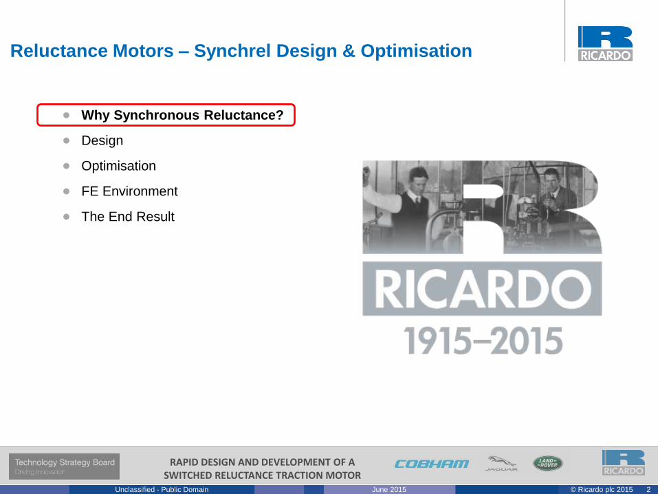
The wide variety of potential powertrain
architectures includes permanent magnet (PM),
AC induction, SR, wound field and others.
The anticipated duty cycle has a much stronger
effect on system design and selection in hybrid
and electric powertrains than for IC engines.
An optimal solution may look very different for
the same vehicle in different use cases.
A well crafted specification requires detailed
knowledge of the requirement and is the
cornerstone of good design.
The eDrive is far more efficient than the engine,
so it can operate away from its optimum
operating point to improve system performance.
Thermal challenges to balance heat flow
between the engine and generator.
The available envelope will always be small!
The selection of the eMachine topology is keyInduction motor:
Torque speed curve with
inverter control
IPM motor:
Performance trends
against load
Synchrel
motor:
Torque-speed-
efficiency map
There are many eMachine topologies. Rapid SR aimed to eliminate Permanent
Magnets by maximising reluctance torque through both SR & Synchrel motors.
Selecting the eMachine
260
Nm
110
6:4 SR Motor:
Torque ripple
variation by stator
& rotor pole
widths
4© Ricardo plc 2015June 2015Unclassified - Public Domain
RAPID DESIGN AND DEVELOPMENT OF A SWITCHED RELUCTANCE TRACTION MOTOR
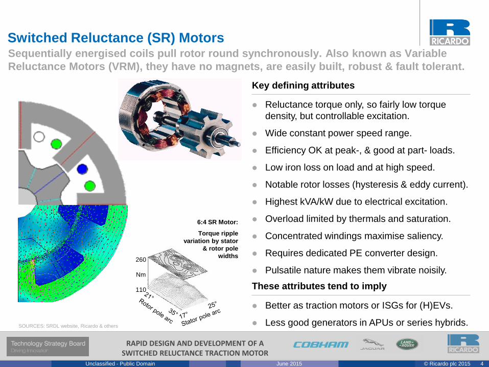
Reluctance torque only, so fairly low torque
density, but controllable excitation.
Wide constant power speed range.
Efficiency OK at peak-, & good at part- loads.
Low iron loss on load and at high speed.
Notable rotor losses (hysteresis & eddy current).
Highest kVA/kW due to electrical excitation.
Overload limited by thermals and saturation.
Concentrated windings maximise saliency.
Requires dedicated PE converter design.
Pulsatile nature makes them vibrate noisily.
Better as traction motors or ISGs for (H)EVs.
Less good generators in APUs or series hybrids.
Key defining attributes
These attributes tend to imply
Switched Reluctance (SR) MotorsSequentially energised coils pull rotor round synchronously. Also known as Variable
Reluctance Motors (VRM), they have no magnets, are easily built, robust & fault tolerant.
260
Nm
110
6:4 SR Motor:
Torque ripple
variation by stator
& rotor pole
widths
SOURCES: SRDL website, Ricardo & others
5© Ricardo plc 2015June 2015Unclassified - Public Domain
RAPID DESIGN AND DEVELOPMENT OF A SWITCHED RELUCTANCE TRACTION MOTOR
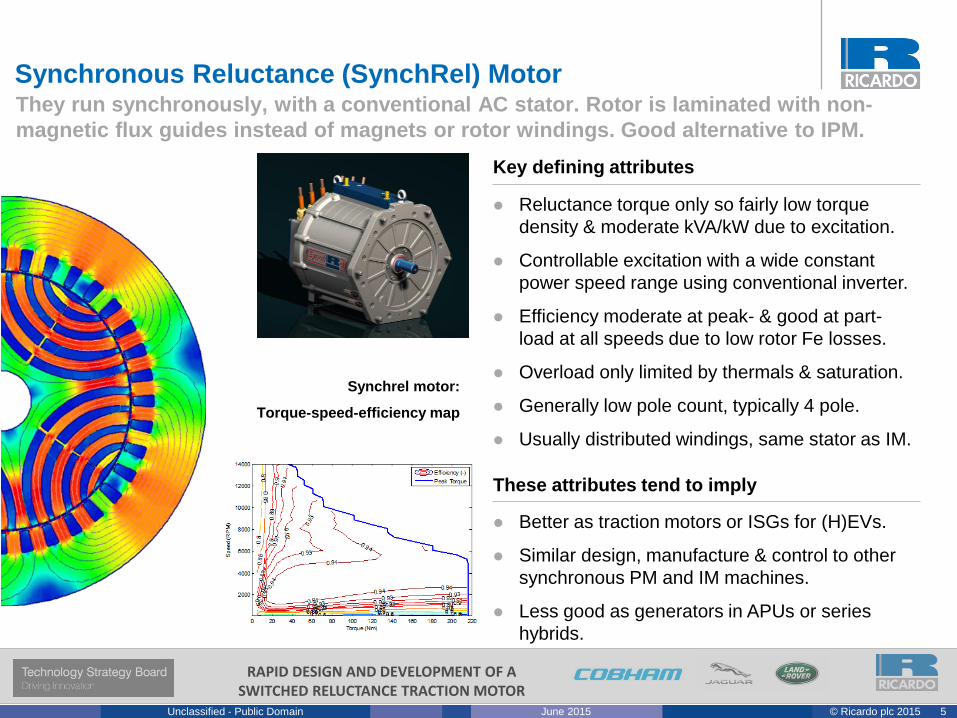
Reluctance torque only so fairly low torque
density & moderate kVA/kW due to excitation.
Controllable excitation with a wide constant
power speed range using conventional inverter.
Efficiency moderate at peak- & good at part-
load at all speeds due to low rotor Fe losses.
Overload only limited by thermals & saturation.
Generally low pole count, typically 4 pole.
Usually distributed windings, same stator as IM.
Better as traction motors or ISGs for (H)EVs.
Similar design, manufacture & control to other
synchronous PM and IM machines.
Less good as generators in APUs or series
hybrids.
Key defining attributes
These attributes tend to imply
Synchronous Reluctance (SynchRel) MotorThey run synchronously, with a conventional AC stator. Rotor is laminated with non-
magnetic flux guides instead of magnets or rotor windings. Good alternative to IPM.
Synchrel motor:
Torque-speed-efficiency map
6© Ricardo plc 2015June 2015Unclassified - Public Domain
RAPID DESIGN AND DEVELOPMENT OF A SWITCHED RELUCTANCE TRACTION MOTOR
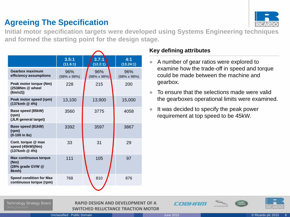
A number of gear ratios were explored to
examine how the trade-off in speed and torque
could be made between the machine and
gearbox.
To ensure that the selections made were valid
the gearboxes operational limits were examined.
It was decided to specify the peak power
requirement at top speed to be 45kW.
Key defining attributes
Agreeing The SpecificationInitial motor specification targets were developed using Systems Engineering techniques
and formed the starting point for the design stage.
Synchrel motor:
Torque-speed-efficiency map
3.5:1(11.6:1)
3.7:1(12.2:1)
4:1(13.24:1)
Gearbox maximum
efficiency assumptions96%
(98% x 98%)
96%(98% x 98%)
96%(98% x 98%)
Peak motor torque (Nm)
(2538Nm @ wheel
(6m/s2))
228 215 200
Peak motor speed (rpm)
(137kmh @ 4%)13,100 13,900 15,000
Base speed (85kW)
(rpm)
(JLR general target)
3560 3775 4058
Base speed (81kW)
(rpm)
(0-100 in 8s)
3392 3597 3867
Cont. torque @ max
speed (45kW)(Nm)
(137kmh @ 4%)
33 31 29
Max continuous torque
(Nm)
(28% grade GVW @
8kmh)
111 105 97
Speed condition for Max
continuous torque (rpm)768 810 876
7© Ricardo plc 2015June 2015Unclassified - Public Domain
RAPID DESIGN AND DEVELOPMENT OF A SWITCHED RELUCTANCE TRACTION MOTOR
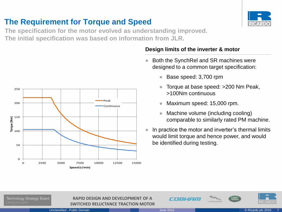
0
50
100
150
200
250
0 2500 5000 7500 10000 12500 15000
Torq
ue (N
m)
Speed (r/min)
Peak
Continuous
The specification for the motor evolved as understanding improved.
The initial specification was based on information from JLR.
Design limits of the inverter & motor
The Requirement for Torque and Speed
Both the SynchRel and SR machines were
designed to a common target specification:
Base speed: 3,700 rpm
Torque at base speed: >200 Nm Peak,
>100Nm continuous
Maximum speed: 15,000 rpm.
Machine volume (including cooling)
comparable to similarly rated PM machine.
In practice the motor and inverter’s thermal limits
would limit torque and hence power, and would
be identified during testing.
8© Ricardo plc 2015June 2015Unclassified - Public Domain
RAPID DESIGN AND DEVELOPMENT OF A SWITCHED RELUCTANCE TRACTION MOTOR
Cobham’s needs
Cobham had developed a variant of their PC-
Opera software for designing SynchRel motors.
It was important that Cobham know the material
properties; the lamination, housing & winding
dimensions; the voltages, frequencies and
currents applied; and the resulting inductances
and torques produced at clearly defined rotor
positions.
The project also included verification of thermal
models, for which Cobham needed to know the
temperature rise against time; the resulting
winding resistance; the thermal performance at
steady state temperature; the thermal
resistances; and clearly identified interface
values wherever possible.
This information was required for a range of
values that included high running speeds and
max torque.
Ricardo also had a role to play in supporting Cobham’s work to develop and validate
a new variant of Opera specifically for designing synchronous reluctance motors.
Developing the FE Environment
9© Ricardo plc 2015June 2015Unclassified - Public Domain
RAPID DESIGN AND DEVELOPMENT OF A SWITCHED RELUCTANCE TRACTION MOTOR
• Why Synchronous Reluctance?
• Design
• Optimisation
• FE Environment
• The End Result
Reluctance Motors – Synchrel Design & Optimisation
10© Ricardo plc 2015June 2015Unclassified - Public Domain
RAPID DESIGN AND DEVELOPMENT OF A SWITCHED RELUCTANCE TRACTION MOTOR
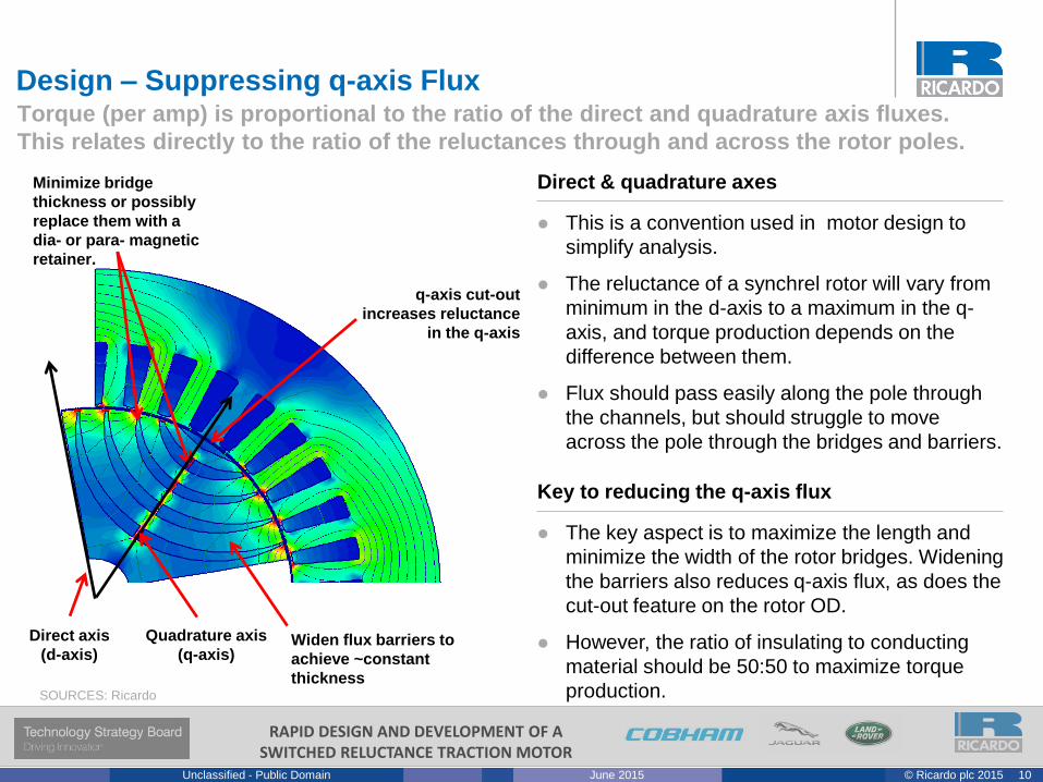
The key aspect is to maximize the length and
minimize the width of the rotor bridges. Widening
the barriers also reduces q-axis flux, as does the
cut-out feature on the rotor OD.
However, the ratio of insulating to conducting
material should be 50:50 to maximize torque
production.
Key to reducing the q-axis flux
Design – Suppressing q-axis FluxTorque (per amp) is proportional to the ratio of the direct and quadrature axis fluxes.
This relates directly to the ratio of the reluctances through and across the rotor poles.
SOURCES: Ricardo
Minimize bridge
thickness or possibly
replace them with a
dia- or para- magnetic
retainer.
q-axis cut-out
increases reluctance
in the q-axis
Widen flux barriers to
achieve ~constant
thickness
Quadrature axis
(q-axis)
Direct axis
(d-axis)
This is a convention used in motor design to
simplify analysis.
The reluctance of a synchrel rotor will vary from
minimum in the d-axis to a maximum in the q-
axis, and torque production depends on the
difference between them.
Flux should pass easily along the pole through
the channels, but should struggle to move
across the pole through the bridges and barriers.
Direct & quadrature axes
11© Ricardo plc 2015June 2015Unclassified - Public Domain
RAPID DESIGN AND DEVELOPMENT OF A SWITCHED RELUCTANCE TRACTION MOTOR
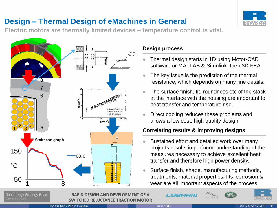
Sustained effort and detailed work over many
projects results in profound understanding of the
measures necessary to achieve excellent heat
transfer and therefore high power density.
Surface finish, shape, manufacturing methods,
treatments, material properties, fits, corrosion &
wear are all important aspects of the process.
Design process
Thermal design starts in 1D using Motor-CAD
software or MATLAB & Simulink, then 3D FEA.
The key issue is the prediction of the thermal
resistance, which depends on many fine details.
The surface finish, fit, roundness etc of the stack
at the interface with the housing are important to
heat transfer and temperature rise.
Direct cooling reduces these problems and
allows a low cost, high quality design.
Correlating results & improving designs
Design – Thermal Design of eMachines in GeneralElectric motors are thermally limited devices – temperature control is vital.
50
150
Staircase graph
calc
°C
1 342 5
6
7
8
1 8
12© Ricardo plc 2015June 2015Unclassified - Public Domain
RAPID DESIGN AND DEVELOPMENT OF A SWITCHED RELUCTANCE TRACTION MOTOR
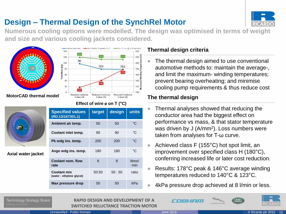
Thermal analyses showed that reducing the
conductor area had the biggest effect on
performance vs mass, & that stator temperature
was driven by J (A/mm2). Loss numbers were
taken from analyses for T-ω curve.
Achieved class F (155°C) hot spot limit, an
improvement over specified class H (180°C),
conferring increased life or later cost reduction.
Results: 178°C peak & 146°C average winding
temperatures reduced to 140°C & 123°C.
4kPa pressure drop achieved at 8 l/min or less.
The thermal design
Numerous cooling options were modelled. The design was optimised in terms of weight
and size and various cooling jackets considered.
Design – Thermal Design of the SynchRel Motor
Axial water jacket
MotorCAD thermal model
Effect of wire ø on T (°C)
Specified values (RD.13/167301.1)
target design units
Ambient air temp. 50 50 °C
Coolant inlet temp. 90 90 °C
Pk wdg ins. temp. 200 200 °C
Avge wdg ins. temp. 180 180 °C
Coolant nom. flow
rate
8 8 litres/
min
Coolant mix(water : ethylene glycol)
50:50 50 : 50 ratio
Max pressure drop 50 50 kPa
The thermal design aimed to use conventional
automotive methods to: maintain the average-,
and limit the maximum- winding temperatures;
prevent bearing overheating; and minimise
cooling pump requirements & thus reduce cost
Thermal design criteria
13© Ricardo plc 2015June 2015Unclassified - Public Domain
RAPID DESIGN AND DEVELOPMENT OF A SWITCHED RELUCTANCE TRACTION MOTOR
• Why Synchronous Reluctance?
• Design
• Optimisation
• FE Environment
• The End Result
Reluctance Motors – Synchrel Design & Optimisation
14© Ricardo plc 2015June 2015Unclassified - Public Domain
RAPID DESIGN AND DEVELOPMENT OF A SWITCHED RELUCTANCE TRACTION MOTOR
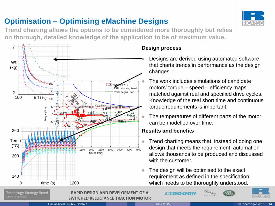
Design process
Designs are derived using automated software
that charts trends in performance as the design
changes.
The work includes simulations of candidate
motors’ torque – speed – efficiency maps
matched against real and specified drive cycles.
Knowledge of the real short time and continuous
torque requirements is important.
The temperatures of different parts of the motor
can be modelled over time.
Trend charting means that, instead of doing one
design that meets the requirement, automation
allows thousands to be produced and discussed
with the customer.
The design will be optimised to the exact
requirement as defined in the specification,
which needs to be thoroughly understood.
Results and benefits
Optimisation – Optimising eMachine DesignsTrend charting allows the options to be considered more thoroughly but relies
on thorough, detailed knowledge of the application to be of maximum value.
2
3
4
5
6
7
8
9
10
-100 -96 -92 -88 -84 -80 -76 -72
Machine efficiency [%]
To
tal m
oto
r w
eig
ht
[kg
]
30krpm 4pole -15 slot
40krpm 4 pole -15 slot
30krpm 2 pole -9 slot
30krpm 4 pole -18 slot
Candidate 3
Candidate 1
60krpm 4 pole -15 slot
Candidate 2
30krpm 6 pole 9 slot
7
Wt
(kg)
2100 Eff (%) 84
0.4
0.4 0.4 0.4
0.4
0.4 0.4 0.4
0.5
0.5 0.5 0.5
0.5
0.5 0.5 0.5
0.6
0.6 0.6 0.6
0.6
0.6 0.6 0.6
0.7
0.7 0.7 0.7
0.7
0.7 0.7 0.7
0.8
0.8 0.8 0.8
0.8
0.8 0.8 0.8
0.83
0.83 0.83 0.83
0.83
0.83 0.83 0.83
0.84
0.84 0.84
0.84
0.84 0.84
0.8
5
0.85 0.85
0.85
0.85 0.85
0.85
0.85 0.85
0.85
0.85 0.85
0.86
0.86
0.8
6
0.86
0.86
0.86
0.87
0.87
0.87
0.87
0.88
0.88
Speed (rpm)
Torq
ue (
Nm
)
0 500 1000 1500 2000 2500 3000 3500 4000 4500
-200
-150
-100
-50
0
50
100
150
200 Efficiency (-)
Peak Motoring Load
Peak Regen Load
0 time (s) 1200
260
Temp
(°C)
200
140
120.0
140.0
160.0
180.0
200.0
220.0
240.0
260.0
280.0
0 200 400 600 800 1000 1200 1400 1600
Time [s]
Te
mp
era
ture
[d
eg
C]
Magnet
EWdg_F
EWdg_R
Winding_Layer1
Winding_Layer2
Winding_Layer3
Winding_Layer4
Winding_Layer5
Winding_Layer6
15© Ricardo plc 2015June 2015Unclassified - Public Domain
RAPID DESIGN AND DEVELOPMENT OF A SWITCHED RELUCTANCE TRACTION MOTOR
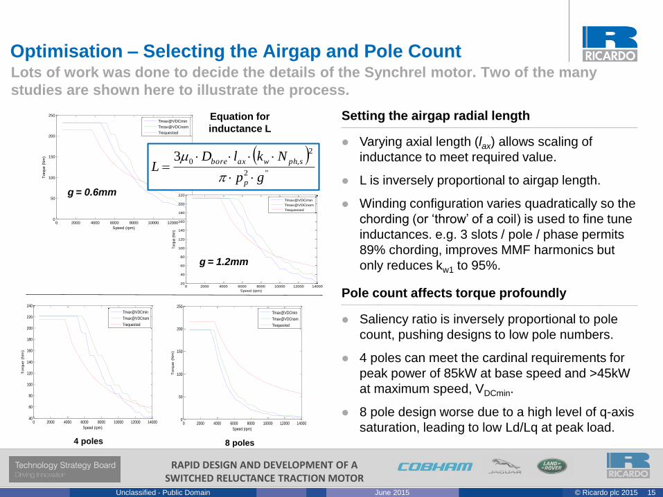
Varying axial length (lax) allows scaling of
inductance to meet required value.
L is inversely proportional to airgap length.
Winding configuration varies quadratically so the
chording (or ‘throw’ of a coil) is used to fine tune
inductances. e.g. 3 slots / pole / phase permits
89% chording, improves MMF harmonics but
only reduces kw1 to 95%.
Saliency ratio is inversely proportional to pole
count, pushing designs to low pole numbers.
4 poles can meet the cardinal requirements for
peak power of 85kW at base speed and >45kW
at maximum speed, VDCmin.
8 pole design worse due to a high level of q-axis
saturation, leading to low Ld/Lq at peak load.
Setting the airgap radial length
Pole count affects torque profoundly
Lots of work was done to decide the details of the Synchrel motor. Two of the many
studies are shown here to illustrate the process.
Optimisation – Selecting the Airgap and Pole Count
0 2000 4000 6000 8000 10000 12000 140000
50
100
150
200
250
Speed (rpm)
Torq
ue (
Nm
)
Tmax@VDCmin
Tmax@VDCnom
Trequested
g = 0.6mm
"2
2
,03
gp
NklDL
p
sphwaxbore
0 2000 4000 6000 8000 10000 12000 1400020
40
60
80
100
120
140
160
180
200
220
Speed (rpm)
Tor
que
(Nm
)
Tmax@VDCmin
Tmax@VDCnom
Trequested
g = 1.2mm
Equation for
inductance L
0 2000 4000 6000 8000 10000 12000 1400040
60
80
100
120
140
160
180
200
220
240
Speed (rpm)
Torq
ue (
Nm
)
Tmax@VDCmin
Tmax@VDCnom
Trequested
4 poles 8 poles
0 2000 4000 6000 8000 10000 12000 140000
50
100
150
200
250
Speed (rpm)
Torq
ue (
Nm
)
Tmax@VDCmin
Tmax@VDCnom
Trequested
16© Ricardo plc 2015June 2015Unclassified - Public Domain
RAPID DESIGN AND DEVELOPMENT OF A SWITCHED RELUCTANCE TRACTION MOTOR
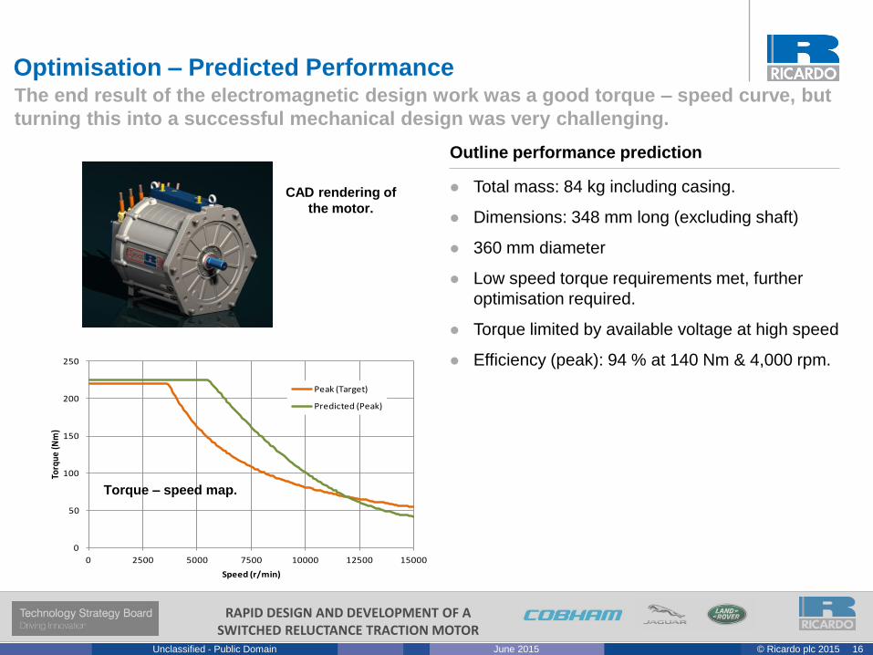
The end result of the electromagnetic design work was a good torque – speed curve, but
turning this into a successful mechanical design was very challenging.
Optimisation – Predicted Performance
CAD rendering of
the motor.
Total mass: 84 kg including casing.
Dimensions: 348 mm long (excluding shaft)
360 mm diameter
Low speed torque requirements met, further
optimisation required.
Torque limited by available voltage at high speed
Efficiency (peak): 94 % at 140 Nm & 4,000 rpm.
Outline performance prediction
0
50
100
150
200
250
0 2500 5000 7500 10000 12500 15000
Torq
ue (N
m)
Speed (r/min)
Peak (Target)
Predicted (Peak)
Torque – speed map.
17© Ricardo plc 2015June 2015Unclassified - Public Domain
RAPID DESIGN AND DEVELOPMENT OF A SWITCHED RELUCTANCE TRACTION MOTOR
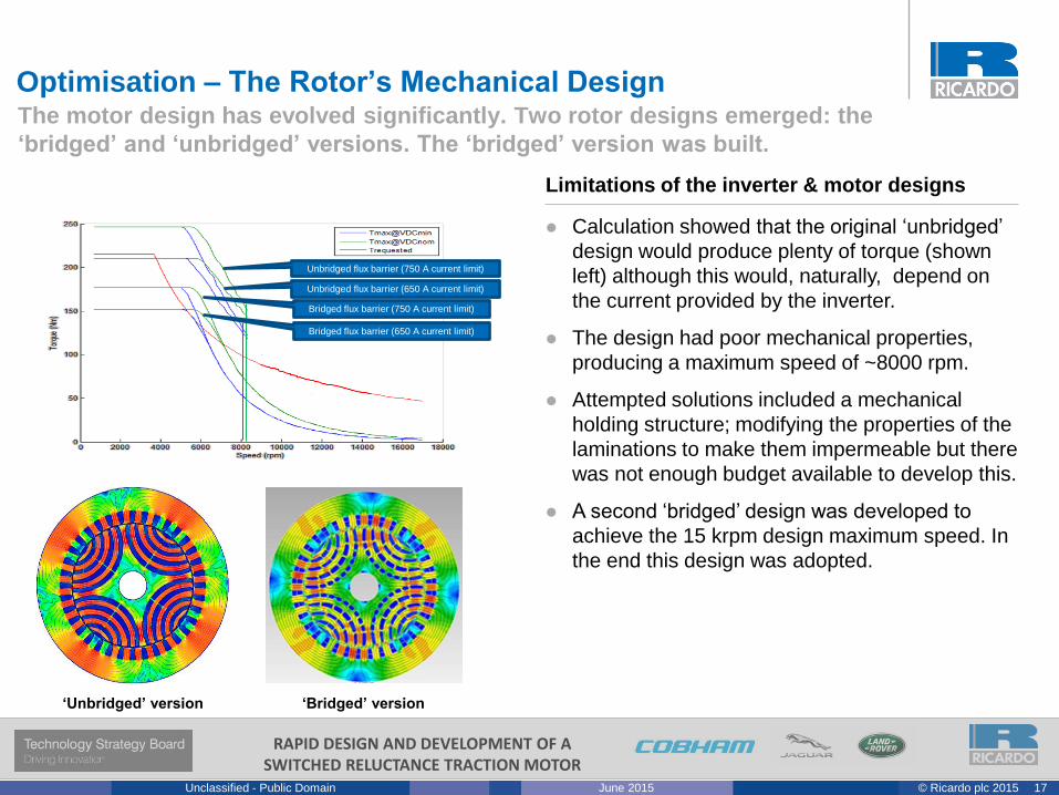
The motor design has evolved significantly. Two rotor designs emerged: the
‘bridged’ and ‘unbridged’ versions. The ‘bridged’ version was built.
Calculation showed that the original ‘unbridged’
design would produce plenty of torque (shown
left) although this would, naturally, depend on
the current provided by the inverter.
The design had poor mechanical properties,
producing a maximum speed of ~8000 rpm.
Attempted solutions included a mechanical
holding structure; modifying the properties of the
laminations to make them impermeable but there
was not enough budget available to develop this.
A second ‘bridged’ design was developed to
achieve the 15 krpm design maximum speed. In
the end this design was adopted.
Limitations of the inverter & motor designs
‘Bridged’ version‘Unbridged’ version
Optimisation – The Rotor’s Mechanical Design
Unbridged flux barrier (750 A current limit)
Unbridged flux barrier (650 A current limit)
Bridged flux barrier (750 A current limit)
Bridged flux barrier (650 A current limit)
18© Ricardo plc 2015June 2015Unclassified - Public Domain
RAPID DESIGN AND DEVELOPMENT OF A SWITCHED RELUCTANCE TRACTION MOTOR
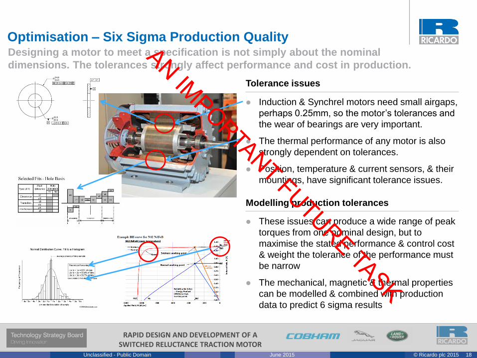
Optimisation – Six Sigma Production QualityDesigning a motor to meet a specification is not simply about the nominal
dimensions. The tolerances strongly affect performance and cost in production.
These issues can produce a wide range of peak
torques from one nominal design, but to
maximise the stated performance & control cost
& weight the tolerance of the performance must
be narrow
The mechanical, magnetic & thermal properties
can be modelled & combined with production
data to predict 6 sigma results
Modelling production tolerances
Induction & Synchrel motors need small airgaps,
perhaps 0.25mm, so the motor’s tolerances and
the wear of bearings are very important.
The thermal performance of any motor is also
strongly dependent on tolerances.
Position, temperature & current sensors, & their
mountings, have significant tolerance issues.
Tolerance issues
19© Ricardo plc 2015June 2015Unclassified - Public Domain
RAPID DESIGN AND DEVELOPMENT OF A SWITCHED RELUCTANCE TRACTION MOTOR
• Why Synchronous Reluctance?
• Design
• Optimisation
• FE Environment
• The End Result
Reluctance Motors – Synchrel Design & Optimisation
20© Ricardo plc 2015June 2015Unclassified - Public Domain
RAPID DESIGN AND DEVELOPMENT OF A SWITCHED RELUCTANCE TRACTION MOTOR
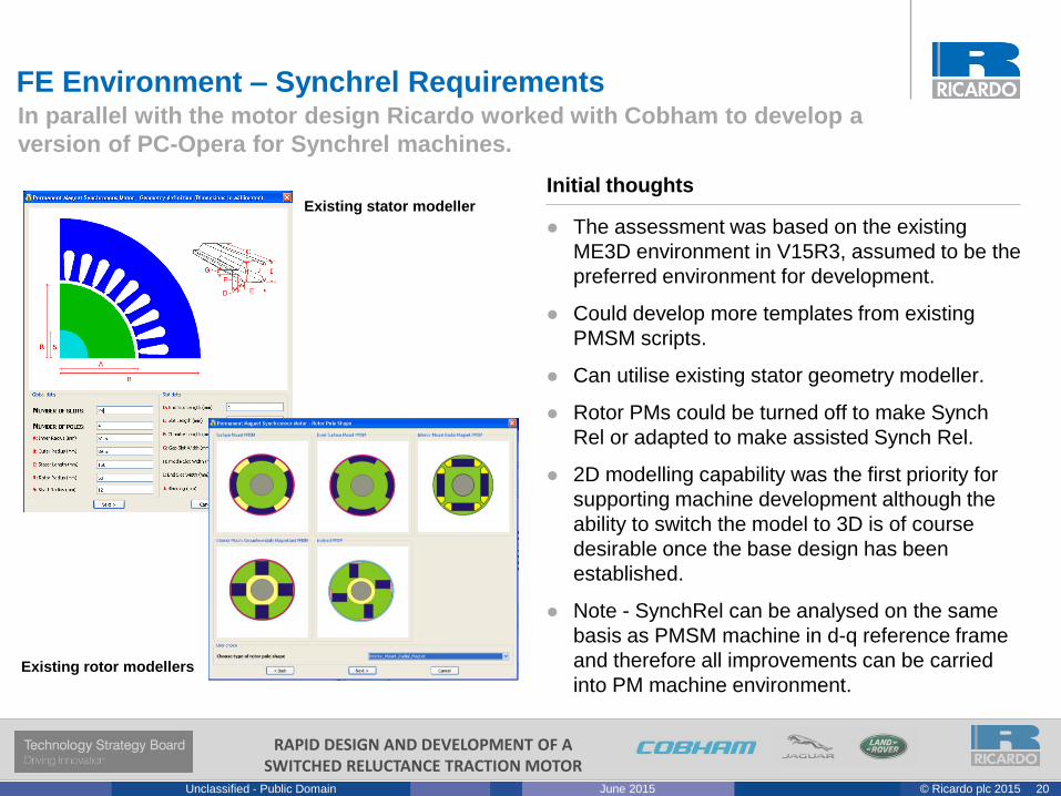
In parallel with the motor design Ricardo worked with Cobham to develop a
version of PC-Opera for Synchrel machines.
The assessment was based on the existing
ME3D environment in V15R3, assumed to be the
preferred environment for development.
Could develop more templates from existing
PMSM scripts.
Can utilise existing stator geometry modeller.
Rotor PMs could be turned off to make Synch
Rel or adapted to make assisted Synch Rel.
2D modelling capability was the first priority for
supporting machine development although the
ability to switch the model to 3D is of course
desirable once the base design has been
established.
Note - SynchRel can be analysed on the same
basis as PMSM machine in d-q reference frame
and therefore all improvements can be carried
into PM machine environment.
Initial thoughts
Existing rotor modellers
Existing stator modeller
FE Environment – Synchrel Requirements
21© Ricardo plc 2015June 2015Unclassified - Public Domain
RAPID DESIGN AND DEVELOPMENT OF A SWITCHED RELUCTANCE TRACTION MOTOR
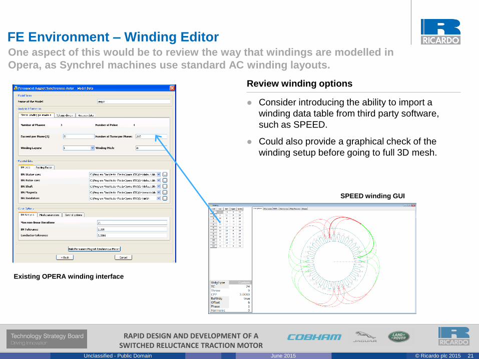
One aspect of this would be to review the way that windings are modelled in
Opera, as Synchrel machines use standard AC winding layouts.
Consider introducing the ability to import a
winding data table from third party software,
such as SPEED.
Could also provide a graphical check of the
winding setup before going to full 3D mesh.
Review winding options
Existing OPERA winding interface
SPEED winding GUI
FE Environment – Winding Editor
22© Ricardo plc 2015June 2015Unclassified - Public Domain
RAPID DESIGN AND DEVELOPMENT OF A SWITCHED RELUCTANCE TRACTION MOTOR
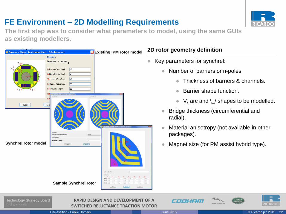
The first step was to consider what parameters to model, using the same GUIs
as existing modellers.
Key parameters for synchrel:
Number of barriers or n-poles
Thickness of barriers & channels.
Barrier shape function.
V, arc and \_/ shapes to be modelled.
Bridge thickness (circumferential and
radial).
Material anisotropy (not available in other
packages).
Magnet size (for PM assist hybrid type).
2D rotor geometry definitionExisting IPM rotor model
FE Environment – 2D Modelling Requirements
Sample Synchrel rotor
Synchrel rotor model
23© Ricardo plc 2015June 2015Unclassified - Public Domain
RAPID DESIGN AND DEVELOPMENT OF A SWITCHED RELUCTANCE TRACTION MOTOR
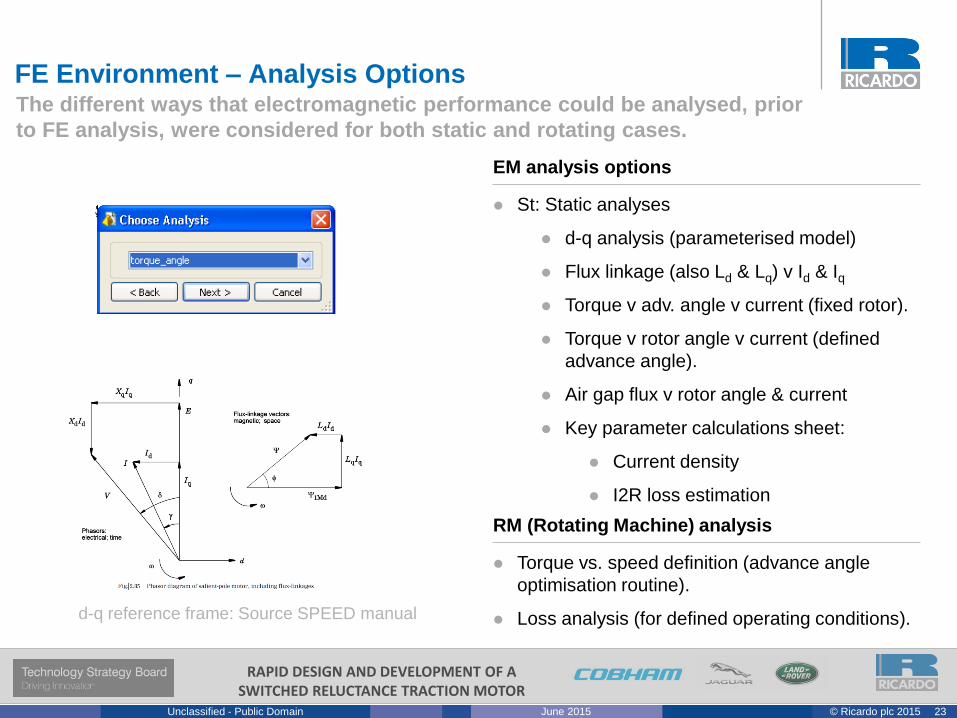
The different ways that electromagnetic performance could be analysed, prior
to FE analysis, were considered for both static and rotating cases.
Torque vs. speed definition (advance angle
optimisation routine).
Loss analysis (for defined operating conditions).
RM (Rotating Machine) analysis
FE Environment – Analysis Options
St: Static analyses
d-q analysis (parameterised model)
Flux linkage (also Ld & Lq) v Id & Iq
Torque v adv. angle v current (fixed rotor).
Torque v rotor angle v current (defined
advance angle).
Air gap flux v rotor angle & current
Key parameter calculations sheet:
Current density
I2R loss estimation
EM analysis options
d-q reference frame: Source SPEED manual
24© Ricardo plc 2015June 2015Unclassified - Public Domain
RAPID DESIGN AND DEVELOPMENT OF A SWITCHED RELUCTANCE TRACTION MOTOR
• Why Synchronous Reluctance?
• Design
• Optimisation
• FE Environment
• The End Result
Reluctance Motors – Synchrel Design & Optimisation
25© Ricardo plc 2015June 2015Unclassified - Public Domain
RAPID DESIGN AND DEVELOPMENT OF A SWITCHED RELUCTANCE TRACTION MOTOR
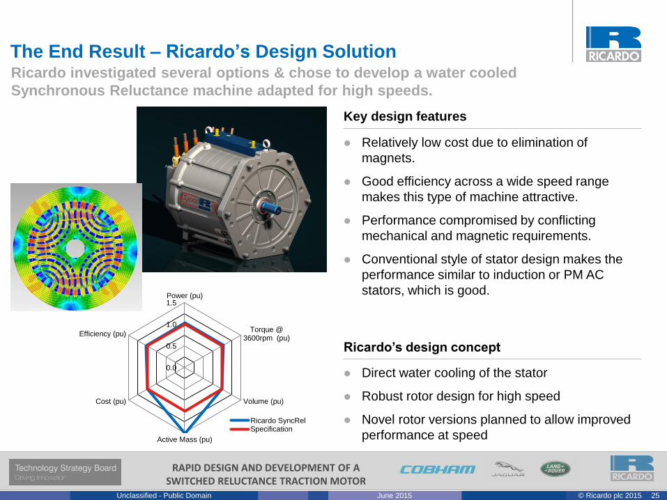
0.0
0.5
1.0
1.5Power (pu)
Torque @3600rpm (pu)
Volume (pu)
Active Mass (pu)
Cost (pu)
Efficiency (pu)
Ricardo SyncRelSpecification
Relatively low cost due to elimination of
magnets.
Good efficiency across a wide speed range
makes this type of machine attractive.
Performance compromised by conflicting
mechanical and magnetic requirements.
Conventional style of stator design makes the
performance similar to induction or PM AC
stators, which is good.
Key design features
The End Result – Ricardo’s Design SolutionRicardo investigated several options & chose to develop a water cooled
Synchronous Reluctance machine adapted for high speeds.
Direct water cooling of the stator
Robust rotor design for high speed
Novel rotor versions planned to allow improved
performance at speed
Ricardo’s design concept
26© Ricardo plc 2015June 2015Unclassified - Public Domain
RAPID DESIGN AND DEVELOPMENT OF A SWITCHED RELUCTANCE TRACTION MOTOR
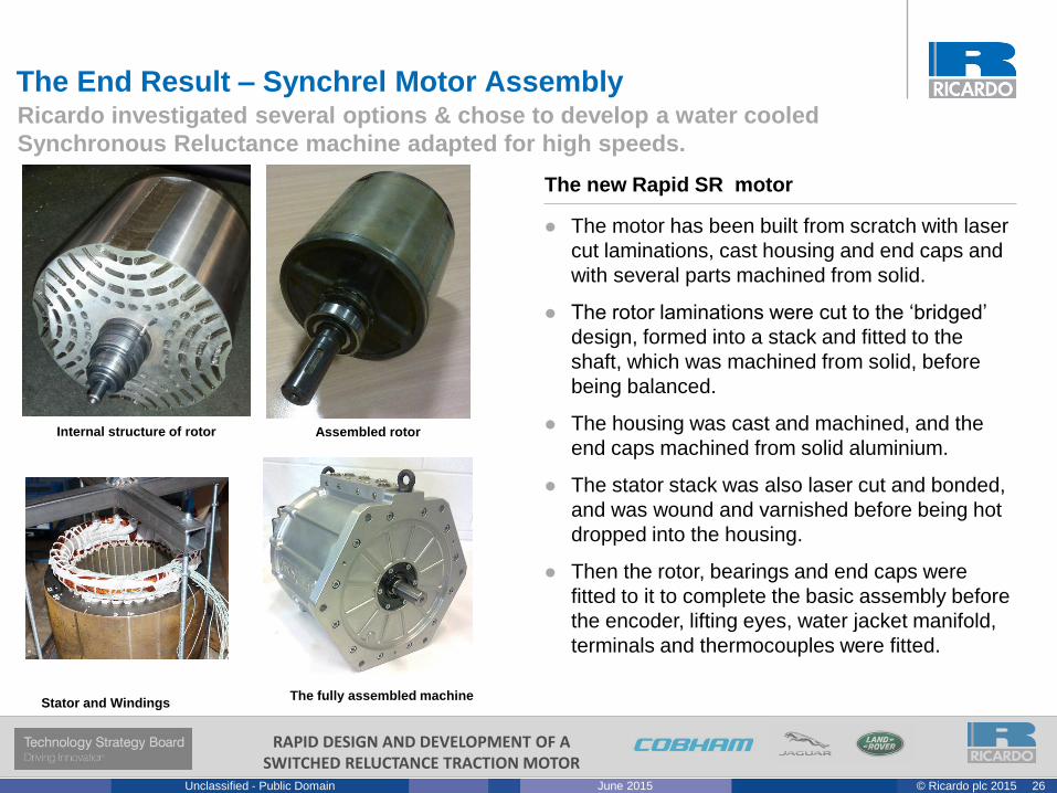
The End Result – Synchrel Motor AssemblyRicardo investigated several options & chose to develop a water cooled
Synchronous Reluctance machine adapted for high speeds.
Internal structure of rotor Assembled rotor
Stator and WindingsThe fully assembled machine
The motor has been built from scratch with laser
cut laminations, cast housing and end caps and
with several parts machined from solid.
The rotor laminations were cut to the ‘bridged’
design, formed into a stack and fitted to the
shaft, which was machined from solid, before
being balanced.
The housing was cast and machined, and the
end caps machined from solid aluminium.
The stator stack was also laser cut and bonded,
and was wound and varnished before being hot
dropped into the housing.
Then the rotor, bearings and end caps were
fitted to it to complete the basic assembly before
the encoder, lifting eyes, water jacket manifold,
terminals and thermocouples were fitted.
The new Rapid SR motor
27© Ricardo plc 2015June 2015Unclassified - Public Domain
RAPID DESIGN AND DEVELOPMENT OF A SWITCHED RELUCTANCE TRACTION MOTOR
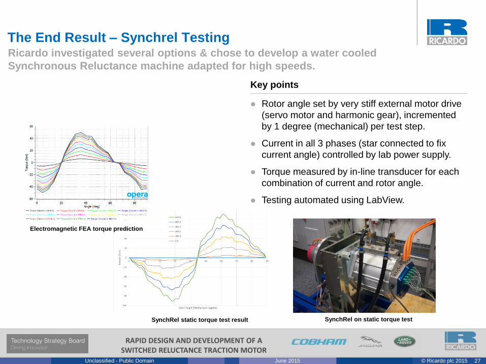
Rotor angle set by very stiff external motor drive
(servo motor and harmonic gear), incremented
by 1 degree (mechanical) per test step.
Current in all 3 phases (star connected to fix
current angle) controlled by lab power supply.
Torque measured by in-line transducer for each
combination of current and rotor angle.
Testing automated using LabView.
Key points
The End Result – Synchrel TestingRicardo investigated several options & chose to develop a water cooled
Synchronous Reluctance machine adapted for high speeds.
SynchRel on static torque testSynchRel static torque test result
Electromagnetic FEA torque prediction
28© Ricardo plc 2015June 2015Unclassified - Public Domain
RAPID DESIGN AND DEVELOPMENT OF A SWITCHED RELUCTANCE TRACTION MOTOR