Embed Size (px)
Citation preview
""
i
t
- * RM No. L7E08 . .
"
RESEARCH MEMORANDUM
MEASUREMENTS O F THE EFFECTS O F THICKNESS RATIO AND ASPECT
RATIO ON THE DRAG O F RECTANGULAR-PLAN-FORM
AIRFOILS AT TRANSONIC SPEEDS
Jim Rogers Thompson and Charles W. Mathews
NATIONAL AD-WSORY COMMITTEE FOR AERONAUTICS
WASHINGTON June 20,1947
OF TBE IWF!ECTs OF TBIccIcNE.SS RATIO AND ASPECT
RATIO ON TBE CWAG OF K E C W ~ - W - F o R M
SUMMARY
As part of bvest igat ion to determine the effect of variaticm of the basic airfoil parameters on airfoil drag characteristics at eramanic and susersonic speeds, a ser ies of recfxngula&plan-form airfoils having aspect ra t ios of 7 .6 and 5.1 and having NACA 65-006, 65-009, and @-OX! sectiom have been tested by the free -fall. method. In t h e present paper results are p ~ ~ ~ ~ t e d for two airfoils of the ser ies (thoee having HACA 65l0E sections and aspect ratios of 7.6 and 5.1) and m e compaJI.ed with results for other a i r f o i l s of the series which w e r e reported previously.
The msults shoved 42ux-b for the a i r f o i l s of thiclmese r a t i o 0.32 t he effect of re8,uctim of aspect ratio w&8 the same aa that previouely determined for t he &foils of thickne~s r a t i o 0.09; reduction of aspect ratfo &layea t he occurrence of the dreg rim by about 0.02 Mach number and reduced the drag a t speede above the drag rise.
A t sonic and low supersonio speed^ the pressure-drag coefpicient waa found t o vwy in proportion t o tale square of the tbiclmess r a t i o between values of t h i c h e s s r a t i o of 0 .Og and. 0.X but between values of t h i c k ~ e s s r a t i o of o .06 and 0.09 the emanent was somewhat less than 2.
IIT2RODUCTION
One of the problems encountered in the design of a trassonic or eupersonic airplane of any fixed configuration is that of seleoting the thickness of the wing section so that adequate s t ructural strength and a safe landing sped m y be obtaFned without penaliz- t h e airplane in high-speed fliwt by excesslve wing drag. It is well known tha t the best combination of strength and landing speed is obtained by use of relative* thick win@; however, thin-airfoi l theory for superemic speeds (reference f and mmy other pyers) predicts that far unswept wings of infinite aspect ra t io the wing drag is proportional to the square of the a i r fo i l - th i chess ratio. Thus a small reduction in wing thickness would result i n a cmsiderable savfng in supereonic wing drag ff the theory -8 directly applicable.
In order t o sovide i"crmt€on on t h i s asLd other -LC problem encountered Tn the desi@ of transonic and Entpersmic airplanes, the National Advisory Committee f o r Aeronautics has instituted a general research grogrmi on the *etg characteristics of airfoil sectfons, wing plan form, body shapes, ana wing-body cmff,watfons a t transonic and supersonfc speeds. As part of this propem, measurements have been made of the d m g of EEACA 65-006, 65 -009, and- 65 -OX? a i r f o i l s haviw rectangular plan f o r m of tvo different aspect ratios. Results obtained f o r the 6- and 9 percent- thick a i r fol le m e reported in references 2 t o 4 m d resuts f o r the 12-percent-thick airfoils are presented i n th i s ppr .
Drag results for t h e a l r f o i l s having XACA 65-012 sectfona w e presented as curve8 showing the variation of draig coefficient with Mach nmiber in t h e t rmson ic sped rq8 . These resul ts are compared w i t h the resul ts of references 2 t o 4 to determine the effects of thickness and aspect ratio an the airfoil &rag. Al though suprsonic thin-airfoi l t heom does not directly apply t o the t e s t reoults preserited because of the rounded alrfofl w e e ( r e s d t h g in mixed subsonic-supersonic flows occurring on the airfoil): f i n i t e thiclmess and aspect retio, possibility of separation effects, and so forth, the t e s t r e s u l t s are compared w i t h tlre theory t o provide some information on t h e importance of these differences.
The tea ts were performed by t h e Flight Research Divfeion of the Langley .laboratory by means of the freely-falling-body-method described in references 2 t o 4.
U.CA RM No. ~ 7 ~ 0 8 3 - .
fspeRATos A M ) METAOD
8
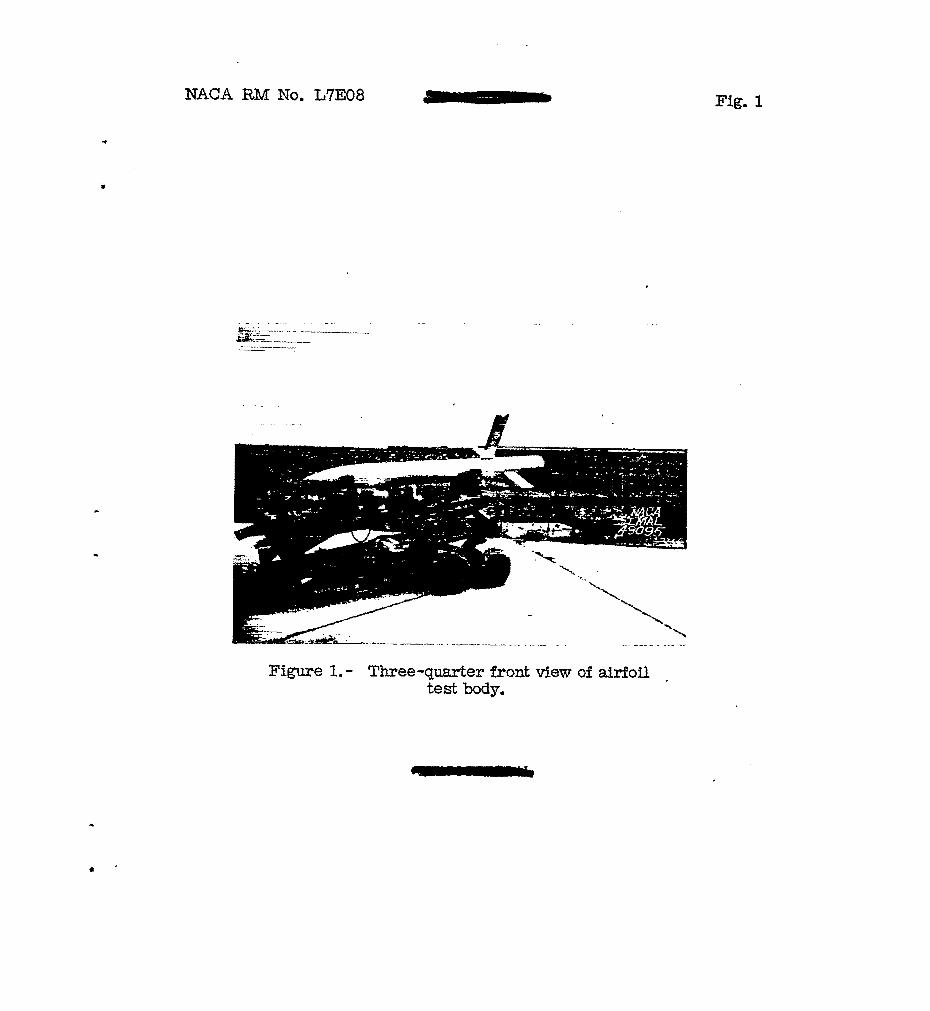
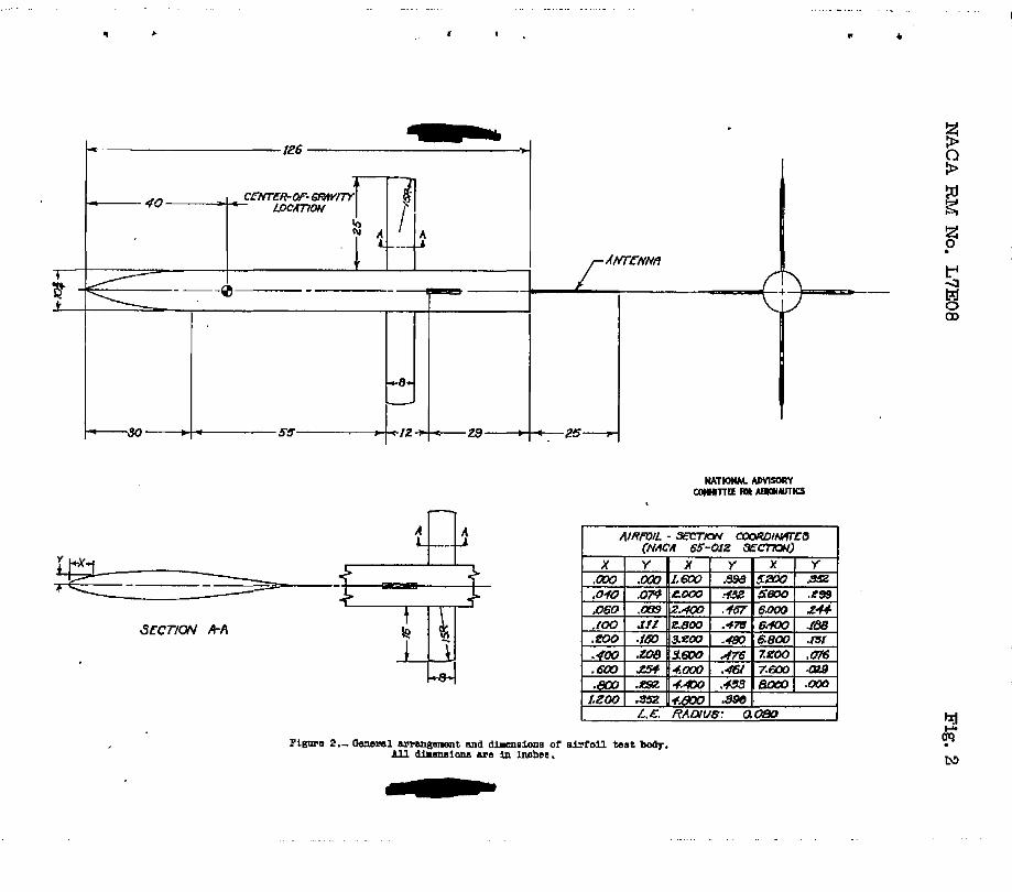
Test b d ~ and amails - The general a;rransemnt of t he b e t configuration is &own by the photograph (fig. I) and the details and dimensions are sham m %he line dra- (f la. 2) . The two test airfoils had rectangular ple;n f o r m ana PACA 65-012 sections of 8-inch chord; the over-all s p m of the front airfoi l w e 60- inches
and that of the rear airfoil vas 4.02 Inchse . The aspect ratios for 4
the t e s t a i r fo i l s (fncluding that p t of the airfoils . c r S t h l n the body) were 7.6 and 5.1. The t e s t -foils entered the born through ret-ular slots 9~ inches long md L inch wfde as did the a i r fo i l8 of references 2 t o 4. Tho Body on which khe a i r fo i l s were mounted had a f la t base ana wa8 identical with tho body used for the t e s t of reference 4. !T!he body aiI'Pered frcm those used. in the tests of references 2 a3la 3 only in t h a t A&e short tail fairing used 011 t h e previous test bodies was replaoed by the flat base.
3 4
1
Measmomen%. = Measurement of the desfred quantities w&8 accmplishoi! as in previoue *eta (references 2 to 4) through use
equipmnt. The following quantities were recorded at two 8epasa-b ground statfons by the telemetering sgste-m:
. of the NACA radio-telemetering sxstem and raclar and photothoodolfte
e
(I) Forco exerted a baly by each test M o i l &B measured by a sprjng balance
(2) T o t a l re"uardatian of body and a i r fo i l s as meamred by a sensitive accelerameter m o d with l c q i t u d f n a l axis of body
A time history of the position of tho body w i t h respect to ground axes during free fa l l w a s reccrded by rad= and photot&eodolite epuipnent, and a survey of atmospheric cmdftions anlying to the t e s t waa obtainod frcm synchronized records of atmospheric pressure, temperatme, and geometric altitude taken during t he descent of the a i r p b e f r o m which the t e s t body was droBed. The direction and swed,of the horizontal comment of the wind in tho range of altitude for w h i c h data axe presented were obta,ined frm raasu. a d photothedolite recmda of tAe pa-tlh of the ascension of a free balloon.
poduction OP data.- As in the previa= tests, the velocity of the body wlth respect t o ground axes, hereinafter referred to as grd velocity, was obtained both bg dif'ferentLatlan of the flight path
b -
4 I U C A RM No. L ~ E D ~
aetermined by radar and phototheoiiolite ecuipment and. by i.nte@ation of the vector of gravitational acceleration and the directed retardation measured by the longitudinal accelerometer. The tmre airspeed w m obtained by vectorially Eta&- the ground velocity and t h e horizontal wind velocity messured at the appropriate altitude.
The drq D of each a i r f o i l was obta.lned from the relation
R maswed reaction betmen airfoil and body, zounds
wT mi@ of a i r fo i l assembly supported on spr- balence, p o m b
reading of accelerometer (retardation), 3
The atmospheric pressure p: t3e tempezture T, and the airfoil frontal -ea F were combined w i t h sirrm.lteneous values of t r u e airspeed and a i r f o i l drag D t o obtain Mach number M and the r a t i o D h . Values of conventional coeff ic ient C were
obtained from t h e relation DF
where the ratio of specific heats y vas taken as 1.4. Drafs coefficfsnts based on plan area C,, were obtained by multiplying the ve.luee of' % by the ratio Gf frontal area t o plan area. Areas
used did not inclcde th&t area enclosed within the body.
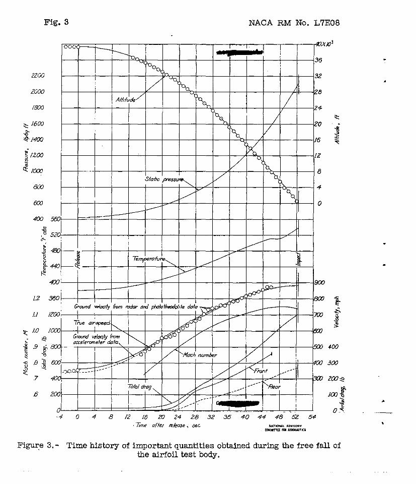
A time histoqr of Important q u a t i t i e s obtained in the premnt test is presented as figure 3 .
mACA €34 No. ~72308 5
The groun6-velocity data obteined from each of the tTro independent methods cf measurement ere presented in f i w e 3; the date, obtahed from the acceleroneter w e shmn as a daahed m e and the data obtained f r o m the redm and ghoto"&eodolite equipent, by the t e e t points. The maar and phototheodolite data are evenly distr lbubd about the a c c e l e r m t e r d a t a but contain a'scetter somevhat lwger than ueual for this equipnmt. Thie scatter result3 f'rom par t i a l farlure of equipment dur ing the test, which necemitated uee of a less precise auxlliaxy record* 6evice. Velocitr data frcm the radar and. Zhotctheodoli'ce e q u i - p n t m e not pwaented fcr the last 6 seconh of the free f a l l as the phobsaphs , which normlly allaw corrsctions to be made f o r -11 tracking errors, were not obtained d u r i i %his period. The t r u e eirspeed ~ras obtained from the gound velocity by u6e of the win& data and is shom on the t i m e history by a solid line. The hkch nuniber was calculated frm the t rue airsgced and temperature data and I s believed accurate within M.01.
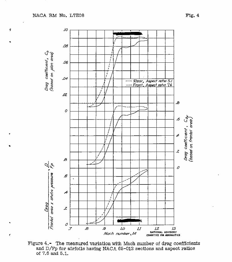
The r e s u l t s of the a i r f o i l i&ag meesurementc aye cmmarized in f l p e 4 where curves are presented which show the measured variatione of D/F2, Ch: md CD for the a i r f o i l s hevlng NACA 65-012 sections
and aspect ratio8 of 7.6 =a 5.1. d
Inasmch as t h e spring b-cee with which the airToi1 drag forces are measured must wtthstand the high drag forces occurring a t supersonfc Mach nmbere a r d h Q h peseures (low al t i tudes) , they axe necessarily relatively insensitive t o the slrall drag forces occurring st subcrit ical Mach ambers and lox pressures (hfgkaltftudes). The h g parmeters are therefore less acc -mte at the lowest Mach nuubers f o r which data are preeented then at eupereonic sgeeds where the &a;: is hi&. The veluea of the r a t i o D/Fp are believed to be accurete %%thin about s .o= a t €4 = o .8 and to within .007 a t M = 1.14. CorrespoadFrg values of C are within -003 a t 14 = 0.8 and within fO .GO25 at M = f. .14. These values correspond t o an error i n dr- meamement of about 1 percent of the full-scale- balance range for values of D / Q ; homver, the =lues of CD include an adfiitioml incremerit (which is appreciable only-.when % is lerge) due t o the -pcssible ur-certa&t-J ir, mcb number of f O .01.
D
!Che drag of the front airfoil exceeds& the r a g e of the tirag balance abo-at 6 seconds before e c t (see fig. 3 ) . No sfgnlficent data were loet,ho.rrever, ae the Mach number aid not increase assreciably after thie tine.
I
The D, -curves of figure 4 show #et for the f ront a i r fo i l F-D
(aspect r a t i o 7.6) the drag rose frm o .02 of etmosmeric pressure
6 - NACA RM No. ~7308
per unit of fron-1 area at M = O . & t o 0.50 a t M = 0.97 and then increased at a sloxor rate to 0.60 at M = I. 14. The drag of t h e rem ~irfoil. (aspect r a t i o 3.1) r m e from 0.02 of atmospheric pressure per unit of fron-kl &rea at .Id = 0.a t o 0.45 at M = 1.00 and then increased to 0.67 at M = 1.15-
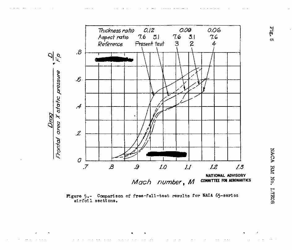
D The --data of figure 4 are compared in f i g m o 5 with results
obtahed in previous free-fall t e s t s o f atrfoila having NACA 6 5 - 0 6 and 65-009 zections . The aepect ra t io , airfoil sectLon, and reference from which those data vere taken are given in tabular form in the figure. Exmineticn of this figure reveaLB thht t h e curves are oi&lar in shape and are nearly parallel dur- the a3ruSt rise which characterizei? the curve6 at Mcch nmibero Juat below 1.00. In thi3 papr., the difference in Mach number beheen these pmallel portions of t h o Lw curves is dsfined a6 tihe kag- rise delay. It ia agj?arent that reducticn in aspect r a t i o or thickness ratio is el'I'ective ir? delqving t h e drag rise to s l igh t ly higher bkch numbers; reduction in aspct rctio *om 7.6 to 5.1 delays the 6rw rise by about 0.02 Mach nmber; & reduction of t h e airfoil-thickness ratio f r o m 0.12 to O.Gg or from 0 .OS e0 0.06 delays the drw rise a similar amount. l'he &&6"rir~e delay remltln(; f'rm reduction in a i r fo i l th ichese is about one -half t h e concomitant increase in the themeticsl critical Mach cumber f o r t h e airfoil secticm.
Fp
The drag-rise delays rasvlting from reduction of aspect ratio and thickness ratio are relatively small with respect t o the over- all accuracy of Bkch nuiber measuremnt (wJ.th3.n -$ .01). The re su l t s presented herein show, however; t ha t the mgn5tude of the drag-riee delay due to redxction of aspect ratio repcrted in reference 3 fo r airfoils h a v 9 q XACA 65-009 sections is about the same (with' An the limit of accuracy of the t e s t s ) for w i n g s having X4CA 65-012 eections.
For aFplication to practical airplane confivatiom, the ma@tude of t h e drq-rise effects premnted heroin may require ~ o m e mo&fficaticn t o account f o r t h e effect of the o y n slot^ "Chro~yh which the airfoile entered the body. The effect of these slotfl is cot known but i s bs l iem& to be e m u . In atfaition. for the airfoile having NACA 65-012 sectiom, a m a l l effect on t h e d ~ ~ y : of the airfoil of aspct ratio 5.1 results fmn! its l oca t im to the rear and ut a ri@t angle to .t;he airfoil cf c s l s z t ratig 7.6 tested cn the EIW body . Previous teats (references 2 and 3) whare identical airfoilr; were tested Fn t h e two posltions showed maximum discrepmcies i n t h e region of t h e drag rise of the Grdm of 0.01 Mach number, the order of accuracy of the MEch nmler meaauremnt.
.
.
XACA RM No. ~ 7 ~ 0 8 - 7
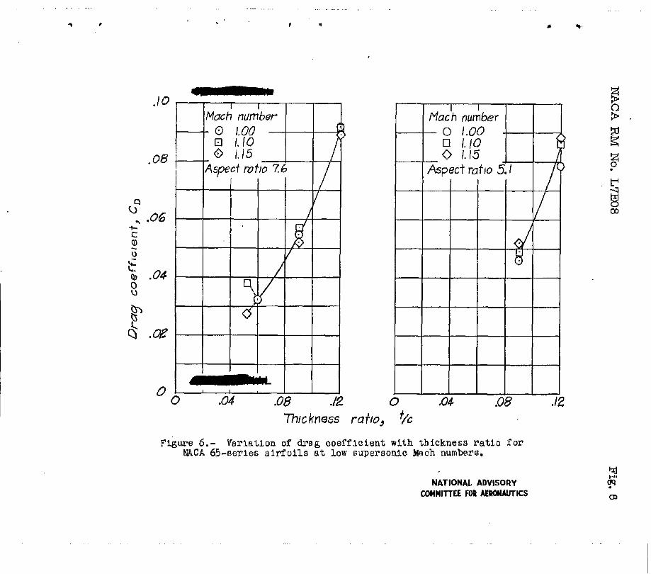
The variation of airfo5l total-drag coefficient CD with th fchess r a t io t / c is shmm L n f i g r e 6. For the a i r fo i l s of, aspect ratio 7.6, an increase EL thickness rat:o from 0.06 t o o .09 resulted in ar, increase in d r ~ coefficient from 0.032 t o about 0.055 f o r Mach n d e r 8 Fn the range e o n 1..00 to 1.15. In the same Mach number range, an jncrease in t;hic);nees r a t i o from 0.09 t o 0.12 resulted in 831. increase in drag coef'f'icient from about 0.055 to 0 .OgO
thickness r a t i o frm 0.09 t o 0.12 resulted in an increase in drag coefficient from about 0 .Ow to 0 .O@.
. Similarls.; f m the airfcil of aspect ratio 5 .I, an increase in
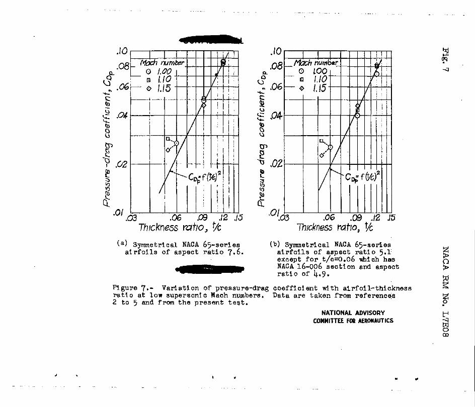
The variation of e i r f o i l 2reasure-drag coefficient C w i t h 4 t h i c h e s s ratio t / c is s h a m plotted in loga?ith?nic f o r n in figure 7 f o r X4CA &-eerie6 e+HoiU at sonic and low supersonic speeds. Separate plots ( f igs . 7(a) and 7(b)) are pm3S8Rted far the two aspect retios f o r which measurements b v e been =de. Airfoils tested in the front position m the body are used i n figure 7(a) but a i r f o i l s tested in the rem posit ion a r e wed i n f igme 7(b) becauae of the limLted mount of t e s t data available. A n est-tmted f r ic t ion-drq coeff ic ient of 0.006 ha6 been subtracted frm the da-b to obtain pressure-drag coefficients.
T h i n - a i r f o i l thecry for auperscmic spoeas, cs preaented in reference 1 m d in nmBrcuB other pagers, leads to the conclusim *et f o r a given Mach nmber and airfoi l section the pressure-drag coefficient i s prcqortimal t o the s q m of' t h e airfoil-thickness ratio. This relation, whfch may be represented in fig- 7 as a sizaight llne Gf slope 2, i s azbitreri ly 2laced on the figure eo tha t it passes thkou& the t e s t points f o r a 'chichess ratio of 0.09. Examination of f i w e 7(a) shms that the test point^ for a thickness ratio of 0.12 lie on the l i ne of slope 2 throug22 the points of thickneso ratio o .og, but the t e s t p ~ ~ t s of thfcknesa ratio 0.06 l i e scmevhat above t h e line. Thus, In the range of 0 .Og to 0 .E, the drag coefficient varies wit!\ thiclmess ratio about as the s2uare of t-lze "&ickness r a t io ) xheraas in the r q e from 0.06 to 0 .Og the exponent is scmchat mailer.
Similar results m e obtained f o r the lorer aspect ratio (fig. ~(b)) a t h o w the pslnts a t thictiness ratio 0.06 me not direct- c m w S b l e ~ L t h the other & & t a g These po;lntai which m e W e n from reference 5, appQ t o alrfo-i ls hslvinz an a e e c t ratio of 4.9, NACA 16-006 sectians,and used as s t a b i l i z i n g tail surfaces f o r a
different from the W-CA 5 5 - 0 6 sectian and as in ifhe t e s t of reference 5 the effect of the location of the a i r f o i l s partljr in t he
., body of reuclutim. As this a i r fo i l section is not a.2preciably
c wake of the body laay be presumed to be lfmitsd to a slight reduction I -
8 k NACA RM No. ~ 7 E o 8
in the drag of tihe airf'olle, the locatian of the t e c t points *om reference 5 above the line of S ~ G P 2 in figme 7(b ) povides additional confkmatlon of the result obaorved 3n f-e 7(a).
Thus, i f the assmption of a constent f'rictian-drag coefficient is vali&, the exprimental results show the same variation of pressure- drat coefficient w i t h t h l c h e s e ratio f o r the thicker a j r f o i l s as that indicated bS.' thin-airfoil theory. The theory is not s t r i c t l y applicable in th i s case, however, because of the rounded airfoil nom ( ree~tx tng IZI atxed subnonic-suporscmic flows occu- r iq on t he airfoil),
and aspect Hattos, and 80 f o r t h . Ae preliminary the problem ina-iates "&at an aCditiona1 variation coefficient w i t h thickness r a t io mi@~t result f r c m p e ~ e u r e drag no t considered in the theory (separation, conclusim can be reached concerning the applicabili ty
It ia considered deairable that f'urther research be yerforrnsd t o d e t e m b e whether the vesiation of d x q coefficient w i t h thichnees r a t d o here obtained is =lid et Mach llumbers beyond the low euper- sonic range, f o r thickr~ess r a t io s eualler than those already teRted, and for ether airfoj.1 sec t ions and plan forms (pe;rticular~a the so-called "eu~er san~c" airfoil Eect-ione). If the t rend here indlcsted at low l&ticlmosa r a t i o s is found t o be generally applicable, the large savinzs i n wing Crag which a r e estimated by mans of ovcpersonic thi2-airfoi l theory to result frcm reducing the airfoil-thicloless ratio would be considercbly reduced end the design considerations In regard to m e of extremely thfn ~ d q s on supersonic a i rc raf t cculd be modified.
Measurements have been made by t_?e f'reely felling body method of the drag of airfoils ham I U C A 65-012 eect ims an2 rectmgula;. plan f o x " of aspect ratio 7.6 end 3.1. Comparison of the results preseEted herein with resul ts of e i m i b r measurements of the drag of a i r fo i l s which had EUCA 63-005 sectiom a d identical aspect ratios and c.f an e i r fo i l which had M C A 65-006 secticna and an a q m t r a t i o of 7.6 rhova that:
2. ReEuction of the t h i c h e m ratio of HACA 65-seriea e i r f o i l s frcm 0.12 to 0.09 and from 0. Op to 0.05 also b h p a the occurrence of drag rise br about 0.02 Mach number. The &%-rice delay which resulted from r e d u c t l a in eirfoil-thfcknees ratio vas &out m e - half the concomitant increaee in the theoretical c r i t i c a l EIach number for the a i r f o i l secttor;.
3. At Mch nunibers from 1 .OO t o 1.15 the presswe-drag coefficient increamd in progortion tc the square of the t h i chees ratio betveen Chichess ratsos .of 0.09 a d 0 . E but increased In proportion t o a smewhat smaller power of the thickness ratfo between thickness ratios of 0.06 and 0.09. Further research should be perforrued t o detemine whether the variation of drag coefficient with thickness r a t i o here* presented is valid for other a l r fo i l sec t ims and at h i a e r mch nmbers and whether the trend is continued a t th i chess ratios l m e r -&an those so fcr tested.
LanQey Memwial Aeromutical Laboratory Xetional Advisory Comaittee f o r Aeronautics
L m g l e ~ Field, Va .
10 NACA RM No. ~ 7 ~ 0 8
1. Lighthill, M. J.: TKo-Dilrensional Supersonic Aerofoil lzleory. r-. R . & M. No- 199, British A . R . C . , 1944.
2. Mathem, Chaxleo W., md Thcnnpson, Jim Rogers : Comprat ive Drag Measurements a t Transonic Speeds of Roctmg111e;r and Swegt- Fack NAC.4 65? -009 Alrfoile. Mounted an a F r e e l y FallFng Body. INCA ACR . No. L5G30, 1945. -
3 . Mathem, Chwlea V., and Thmsm, Jim Rogers : Drag Measuremento at 'pramanic Speeds of IUCA 6 5 ~ 0 9 Airfoils Mounted on a Ersely FaLIAw Body t o Determine tlm Effects of Sweepback and Aspect Ratio. MACA RM No. L ~ K O ~ C , 1947.
4. Thoqpson, J i m Rogers, and Ma;t.ch-er, Bernard W. : Compwetive Drag &leasurerrents a t Transonic Speeds of an NACA 63-006 Airfoil and a Symmetrical Circular -arc Airfo i l MACA RM No I,6J3O, 1946.
5 Bailey, F I J., Jr , Mathem, Charles W., and Thompson, Jim Rogers: Drag Measurements at Tr~m~mxLc S p e b an a Freely Falling Body. NACA A m No. L5EO3, 1947.
NACA RM No. L7E08
r
Fig. 1
Figure 1.- Three-quarter front view of a i r f o i l .
test body.
. - .. . . .
* , -. . . . . . . . . . . . . . . . .
1 .
c . -1 126
.- . . . . . . .
I c
I
” -
-80- ” n
E
4 M 0 03
r
22 w
Fig. 3 NACA RM No. L7E08
f.2
Li
8
L
.
P
Figure 3.- Time history of important quantities obtained during the free f a l l of the airfoil test body.
NACA RM No. L7E08
. L
c
.7 -8 .9 1.0 IJ I 2 13 r /wmbeu~ COMMITTEE F[wI AERUNAUTICS
NATIONAL ADVISORY
Figure 4. - The measured variation with Mach number of drag coefficients and D/?$ for airfoils having NACA 65-012 sections and aspect ratios of 7.6 and 5.1.
. " . . .. . . . . .
QI $ r
Z
C 3
. . . . . . . . . . . . . .
. . . . ... .
1 +
.. . . . . . . . . . . . . . . . . . . . . . ,
I 'I
.. . . . .
* T
77wkness raflo, ?+ Figure 6.- Variation of d r a g c o e f f i c i e n t with th ickness ra t lo for
U C A 65-aeries a i r f o i l s a t low supersonic Mch numbers.
NATIONAL ADVISORY COnWlTTEE FOR AERONAUTICS
. . . .. . . . . .. . .
. . . . . . . . . . . . . . . . .
(a) Symmetrical NACA 65 - ser i e s a i r f o i l s of aspect rat io 7 .6 .
(b) Symmetrical NACA 65-seAea a t r f o i l s of aspect rat io 5.1 except for t/c=o.o6 &ich has NACA 16-006 s e c t i o n and aspect r a t i o of 4.9.
Q * ki
Ngure 7.- Variation o f pressure-drag coefficient with airfo i l - th ickness z r a t i o a t low supersonlc Mach numbers. Data are taken from references 2 t o 5 and from the present t e s t . 3
COHHITTEE F a AERONAUTICS 4
0 M 03
NATIONAL ADVISORY r
J
. . . . . . . . . . . . . . . . - -.
I I r,
. . . .
II'
II
~r.J~09 (iHC14l)
Thompson, J. R: Mathews, C. W.
AUTHOR!S)
'" ZCy ~ @(@C~:::::::;::AAoiIiC.l!. c - ~ -6~3 ~ 'U'Oo 61 6
DIVISION, Aerodyna mic s (2) 9 OOIG. AGE~~ ~Mllfa . SECTION, Wings and Airfoils (6) IW-L7El)(' ~ CROSS REFERENCES, Airfoils - Aerodynamics (07710); ~iI- .:;,:'}.
Airfoils - Drag (08200); Drag - REVISION ' Transonic 01320 l
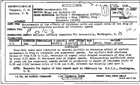
AMER. TITLE, Measurements of the effects of thickness ratio and aspect ratio on the drag of rectangular-pIan-form airfoils at transonic speeds
FORG'N. TITLE, P .. /Ie ",2. _ . '. ~ /" ORIGINATING AGENCY, N$1onal AdV~orY Colmdtl.ee1'or Aeronautics, Washington, D. C':) TIlANSLATION,
COUNTnY I LANGUAGE lFORG'N.cLAS~ V. s.cLASS'1 DATE .1 PAGEST/llUS'T FEATURES U.S. Eng. I. IConfd'l Jun' 47 1 17 1 7 photo, diagr, graphs
~OO'iTM~ Free-fall tests were ccnducted on several airfoils to determine effect of airfoil
parameters on drag at transonic and supersonic speeds. For airfoils with thickness ratios of from 0.06 to 0.12, reduction of aspect ratio delayed occurrence of drag rise by about 0.02 Mach; it decreased drap at higher speeds. Pressure-drag coefficient -l"tlUo' at sonic. and low supersonic speeds varied in proportion to square of thickness ratio of 0.09 and Oi12;' between ratio of 0.06 and 0.09, exponent was slightly less than 2.
NOTE: &qUQsts for copios of thio roport must bo oddrooaod to. N.A.C.A., \IllQhingtcm, D. C. .
T-2, IIQ. AIlI MATERIEL COMMAND ZS;;=1~NICAL ONDEX WRIGHT FIUO, OHIO, USAAf ~~I!. \1f-O..20tlAJIQ'J<1
UNCLASSlFlEDper authority C?fNAC:::A. Research Abstracts No.7.0_~. dated 21 sepumiber 1954. (14'- :Oct54) , . . , ·
5? ,,' 15',' ?-~') ~Y'Q!7 ..,: ~~~Al ! . s-v (1Jj.ltI~
"
. ~ '1<) } '1.1-~'~~?tI r~3~}J'