Embed Size (px)
Citation preview
1 r
",
J
J.
Inactive " 1\ t.i i;) \) l~'" J~\' UNCLASSIFIED
:r.0. 11 ~ -2 ...2..t. ' If.A. /~..).:ct RM No. L7A31
RESEARCH MEMORANDUM: for the
91vil Aeronautics Administration, Department of Commerce
ESTIMATED FLYING QUALITIES OF THE
MARrIN MODEL 202 AIRPLANE
By
Joseph Weil and Marsaret Spear
Langley Memorial Aeronautical Laboratory . Langley Field~ Va •
. CLASSIFIC!\Ti001 CANCELLED
By h.,.~--t/-i,~-I-a-:'----_---~ee ------~---~ ---------------------------------
NA llONAl ADVISORY COMMITTEE FOR AERONAUTICS
WASHINGTON
JAN 241
UNCLASSIFIEO . .i

NACA EM No. L7AJ,1
~-~~ --- ---~-.-
"mI"ljmllllrl~m' . 3 1176014375001
.'1 ._c UNCLASSIFIED
NATIONAL ADVISORY COMMITTEE FOR AERONAUTICS
RESEARCH MEMJRANDUM
for the
Civil Aeronautics Administration, Department of Commerce
ESrIMATED FLYING QUALITIES OF THE
MARTIN MODEL 202 AIBPL.A.b"E
By Joseph Weil and Margaret Spear
ADDENDUM
A conference on the Martin model 202 flying qualities estimations was held on January 20, 1947 with representatives of the Glenn L. Martin Company and the Civil Aeronautics Administration. At this time, it was learned that the 'positive range of the adjustable stabilizer on the prototype a1rplane had been changed from 4.40 to 2.50 . In addition, the maximum up and down elevator angles were increased by 50. These changes should substantially improve the marg!.nal elevator control problem. in the landing condition at the foremost center-of'-gravity position.
It was also learned that the Martin Company estimated the wing 10
dihedral to be increased by about 1'4 1n level flight as a result
of' structural deformation. No account was taken of the def'ormation 1n the analys1s, therefore, it would be expected that the adverse dihedral eff'ect cited Will be some'What alleviated.
UNCLASSiFIED
NACA RM: No. L7A3~
NATIONAL ADVISORY COMMrrl'EE FOR AERONAt7l'ICS
for the
Civi~ Aeronautics Administration, Department of Commerce
ESl'IMATED FLYING QUALITIES OF THE
MARTm MODEL 202 A.IRPLANE
By Joseph Weil and Margaret Spear
SUMMARY
The flying qualities of the Martin mode~ 202 airplane have been estimated chief~ fran the results of' tests of' an 0.0875-scale complete mode~ with power made in the Wright Brothers tunnel at the Massachusetts Institute of Technology and from partial span wing and isolated vertical tail tests made in the Georgia Tech Nine-Foot Tunnel. These estimated handUng qualities have been compared 'With existing Army-Navy and. CAA requirements for stability and control.
The results of the analysis indicate that the Martin model 202. airplane will possess satisfactory handling qualities in all respects except possibly in the following:
The amount of elevator contro~ available for landing or maneuvering in the ~anding condition is either marginal or insufficient when using the adjustable stabi~izer linked to the flaps. Moreover, indications are that the longitudinal trim changes W1l~ be neither large nor appreciably worse With a fixed stabilizer than with the contemplated arrangement utilizing the adJustable stabl1izer in an attempt to reduce the magnitude of the trim changes caused by flap deflection.
The available rudder control will probably enable landings to be made in crose Winds at 900 to the path of only 11 percent of the stalling velocity for some conditions.' This condition could probably be improved considerably; Chiefly by using somewhat less than full flap deflection.
ConSiderable nesative dihedral effect is probable in the landing and approach conditions Which could make t.lte airp~ne difficult if not dangerous to fly.
2 NACA EM No. L7A3l
The aileron ~oroes in abrupt r~lls at "cruising speeds are somewhat higher than the desired limits. Moreover, at the lower speeds the aileron forcea are undesirably low or overbalanced. No ohange in the linkage arrangement o~ the linked -balancing tab would be likely to ~prove the control forces for one condition without having a detrimental effect on the othe~. . However, it is shown that a spring-tab arrangement can be devised to provide reasonably satisfactory characteristics for all conditions.
INTRODUCTION
At the request of the Civil Aeronautics Administration, Department of CommarcQ, an estimate was made of the handling quali ties of the Martin model 20~ transport. This analysis was desired by the CAA as an advance indication of the flight oharacteristics to be anticipated for the prototype airplane. Availability of such knowledge was believed important from the standpoint of safety, facility in planning the flight-test program and subsequently in expediting the tests themselves.
It was originally planned to base the estimations on the results of complete model tests to be made in one of the Langley 7- by lO-foot tunnels. However, a rather extensive investigation by the Martin Cam~any of a complete model of the Martin model 202 had already been made at the Wright Brothers tunnel at M.l.T. (See references 1 to 4.) In addition, detailed isolated vertioal tail tests and tests of a partial ~pan Wing to obtain aileron characteristios had been made at the Georgia Tech nine-foot tunnel. (See re~erences 5 and 6.) Therefore, although the investigations did not cover all of the pOints desired for a oomplete estimation o~ handling qualities, the time-saving element prompted the ~c1aion to use these data which were already availablo.
COEFFICIENTS AND SYMBOLS
The folloWing coeffiCients and symbols appear in the text and figures:
Ch hinge-moment coe~ficient of a control s~f'Bce (H/qb '#) rate of' change of h1nga-mament coefficient with tail angle
of attack
"'i
NACA RM No .. L7A31 3
rate of change ot hinge-moment coefficient with control-surface deflection '
rate of change of contro1-surface hinge4nament coefficient With tab deflection
~ 1ift coefficient (Lift!qS)
Tc' effective thrust coefficisnt(effecti;: thrust)
it
CL-
CLt
13
g
Vi
~
VSr.,
VSG
Vs p
Vs ~
Vp
V
contro1-surface deflection With respect to chord line, degrees
stabilize~ setting with respect to wing root chord 11ne, degrees; posi~ive when trai1ing edge is doWn
angle of attack of wing root chord, degrees
angle of attack of tai1 surface, degrees
sideslip angJ.e, degrees
aqce1eration due to gravity (32.2 feet per second)
indicated airspeed ~'96~p:~)' mnes per hour
neutral-point location, percent mean aerodynamic chord
stalling speed in the landing condition, power off, miles per hour
stalling speed in the glide condition, power off, mi1es per hour .
stalling speed in the climb condition, 75 percent norma1 rated power, miles per hour
stal1ing speed in the approach condition, 45 percent norma1 rated power, miles per hour
design maneuvering speed (see reference 7)
true airspeed, feet per second
4
Fw
P
R
q
b
b'
-c
w
s
p
NACA EM No. L7A3J.
Wing-tip helix engle, radians
rudder pedal force, pounds,
elevator or s11.eron whe~l force, pounds
wheel deflection, degrees
rolling veloCity, ra4ians per second
, hinge moment of a 90ntrol $Ul"faoe I pound -feet
dynamic pressure (pV2/2.), pounds per square foot
wing span, feet
(With subscripts) ~pan of a control surface, feet
root-mean-square chord of a control surface behind hinge line, feet
airplane gross we:J.ght, pounds
wing area, square feet
mass density of air, sluga per cubic foot
mass denSity of air at sea level (0.002378 slug per cubic foot)
Subscripte:
e elevator
r rudder
a a11eron'
f landing flap
ebt ele.a~or linked balance tab
8tt elevator trim tab
rst rudder spring tab
NACA EM Not. L7A3~
rtt. rudder trim tab
abt ai~eron linked balance tab
att ai~eron tr~ tab
Abbreviations:
Wm
c.g.
eM
M.I.T.
propellers Windmi111ng
take-off power
norma1-rated. power
center of gravity.
~ng mean aerodynamic chord., feet
Civil Aeronautics Administration
Massachusetts Institute of Technology
AIRPLANE AND MODELS
.'
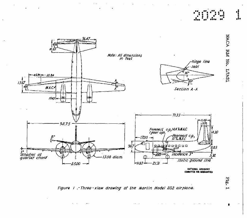
The Martin mod.el 202 airplane is an ali-metal, lOW-Wing, tWinengine monoplane with full cantilever wing and. tail. surfaces. A three-view drawing of the airplane is presented in figure 1. Among the design features are a fully retractable tricycle type a1iSh~ing gear with steerab1e nose wheel, double-slotted flaps interconnected by mechanical mean~ to an adjustable stabilizer for the purpose of minimizing tri:!n. changes' when the flaps are lowered or raised and. a vane type (Van Zelm) aUeron (see fig. 1) for which a smaller aileron can be used than is customary to obtain the same maximnm r.o11ing effectiveness, thus permitting the flap span to be increased.
The elevator and rudder can be aerodynamically balanced by an unsealed overhang and either a linked-balance tab or spring tab~ The ailerons are aerodynamically balanced by a sealed overhang and a linked-balance tab.
A summary of the physical characteristics of the airplane furnished by the manufacturer is presented in tables I, I:I, a.nd. In t.
The complete model tested. at M.I.T. was a 0.0875-scale model With power. Detaile of the model are given in references 1 to 4.

6 NACA EM No. L7A3l
A description of the O.30-soale vertical tail model and the 0.25-soale partial span wing panel model tested at Georgia Tech can be found in references 5 and 6, respectively.
TESTS AND ANALYSIS
Tast conditio~.- Most of th~ tasts in the Wright Brothere tunnel at M.I.T. were conducted at a dynamic pressure of 16.37 pounds per square foot which corresponded to an airspeed of about 80 miles per hour. The test effect:\.ve Reynolds number was about 666,000.
The tasts in the Georgia Tech wind tunnel of the vertical tail model and. of the partial apan wing model were made at a dynamic pressure of 25.58 pounds per square toot lIDich corresponded to an airspeed of about 100 miles per hour. The test effective Reynolds numbers were ~bout 3,920,000 and 2,758,000, respectively-
Model configurations and power conditiona.- The various airplane flight conditions were simulated in the complete model tests by a suitable variation of model confisuration and power condition. The conditions referred to repeatedly ,in this paper are summari~ed 1n the following table:
Airplane Model configuration
flight Landing Landing condition flaps gear Power
Gliding Retracted Up Propellers off Cru1'slng Retracted Up 75-percent N.R.P. Climbing Retracted Up 75-percent N.R.P. Approach 350 Down 45-percent N.R.P.
Landing 550 Down Propellers windmilling
Methode of Analysis
The Martin model 202 airplane is a commercial transport and hence is required to meet the stability and control requirements of the CAA (reference 7). However, the flying qualities have been analyzed using the latest Army-Navy specifications for stability and control as a guide (reference 8 or 9). This was done primarily
..
NACARM No. L7A31. 7
because of the more specific nature of these requirements for class II airplanes (transport category) as compared to the rather general coverage of the OM requirements. 'Where important· differences exist between the two sets of specifications which have a critical bearing on the estimations sUitable,reference is made in the text. It is to be noted that often the conditions for which model data were obtained did not correspond exactly to those specified in referenceS 8 or 9. ~stances where these differences have a ~ertlnent bearing Will also be brought out in the d1sc~sion.
'Xhe normal operating weisht of the Martin model 202 transport is around 36,000 :pounds {"'TIs = 4l .. 9} .' However, a majority of the power~on co~lete model tests were run pains a thrust coefficient variation based on a weight of 29,000 poundS (W/s = 33.7) and. . therefore it was often necessary to base estimates on this latter weisht. All estimates were made for the mean· operational or d'es'ign. center-of-gravity location unless otherWise t?pecif1ed. A weight-balance summary 1s given in table IV. ' .
The f].ying qualities of the airplane beve peen estimated. from the data reported in references 1 to 6 using methods similar to those outlined in references 10 to 13. It was assumed that the control surfaces are mass-balanced, that there is no friction or stretch in the control systamand that there is no fabric distortion. The pow/j:Ir-off stalling velocities of the airplane were based on values of ~x which were obtained. by extrapolating
the complete model tunnel data.
No hinge-moment data were available from which the control forces of the elevator could be estimated directly. Values of Cbat(O) and Ch5(-0.0037~/q) were therefore estimated
utilizing the lifting surface theory of refer~nce 14 and the results of hinge-moment correlations summarized in reference 15-The hinge moments were then estimated USing the ~ Iq calculated from complete model pitching-moment data. The tab effectIveness (Ch6t = -O.0047~/q) which was used to dot ermine the effects of a
linked balance tab and trim tab was obtained using the methods outlined in reference 16. The linkage factor which was used to convert the surface hinge moment to wheel force was supplied. by the manufacturer and is presented in figure 2 ..
In instances Where only propellers-off data were available, the effect of the Windmilling propellers on stability was estimated using the methods of reference 17.
8 NACA EM No.: L7A31
The rotary derivatives which were used in est1mating the dynamic stability characteristics of the airplane were calculated using the methods of references 18 to 20.
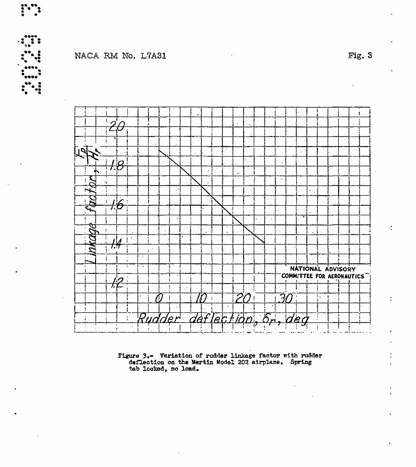
The rudder-control characteristios were computed using both complete model data (transferred to the stability aXis) and the results of the isolated vertical tail tests. The angles of attack· and tail loads required for trim were obtained from· complete model tests. The rudder deflection required for trim and. the rudder hinge moments were obtained from the isolated tail tests. It was possible to estimate the approx1lilate effective aspect ratio of the vertical tail using the lil)11ted rudder data 8vatlable from· complete model testa. The isoleted tail data were then corrected to this aspect ratio. The yawing ·moment due to the aileron deflection· . required for steady sideslips was accounted for. Calculations were made for only one of the·several possible rudder-balancing arrangements, namely, an unpreloaded spring tab with a spring constant of 12 pounds per degree tab deflection. This spring . strength was chosen primarily to provide acceptable forces in the critical asymmetric-power condition. A curve of rudder.linkage factor against rudder deflection is presented in figure 3. .
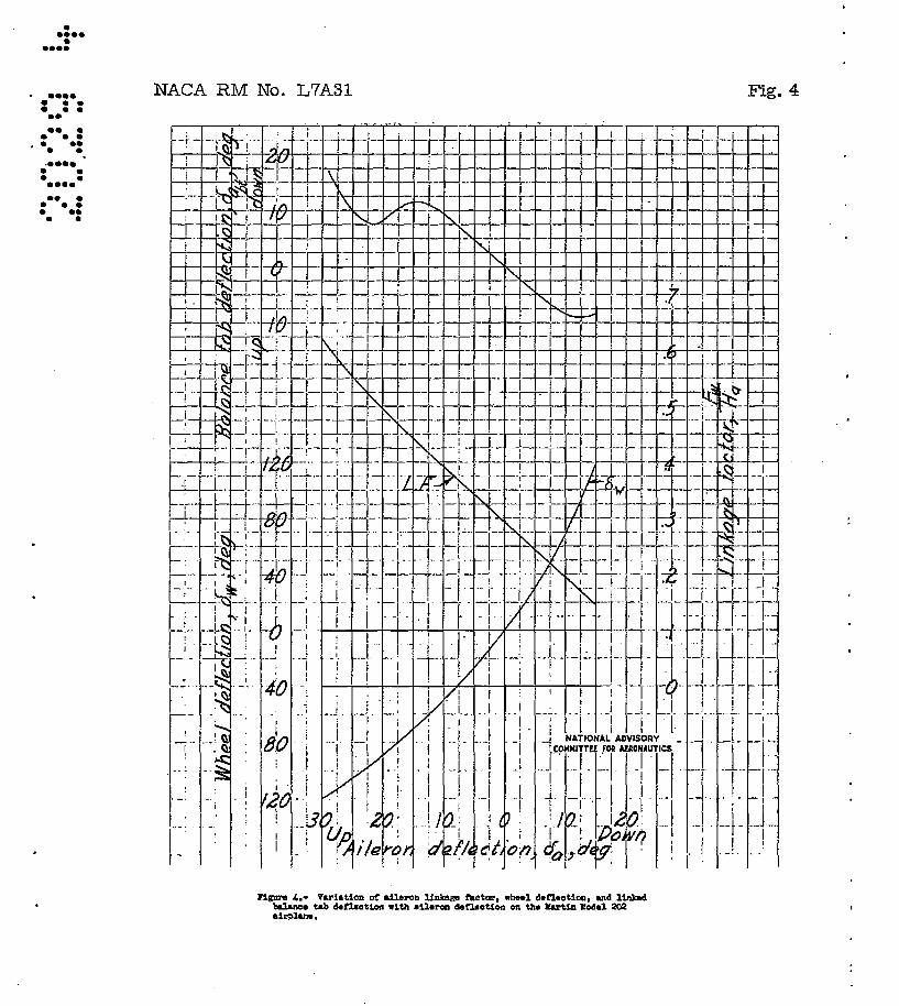
The aileron-control estimates were based on the results of the partial span wing tests made at Georgia Tech. The· tunnel· corrections were computed from reference 21 and it was found that the rolling-moment coefficients presented in reference 6 were about 8 percent too high, This was taken into oonsideration in the computations. Curves show~ng the nonlinear linked-balance tab deflections and linkag& factor against ailero:Q,. deflec.tion are presented in figure 4.
EsrIMATED FLYING QUAL;rTIES
The ~~Navy requirements are divided into four main sections in references 8 or 9, namely: .
D - Longitud.1na,l. Stability and Control E - Directional Stability and Control F - .La·teral Stabil1 ty and Control G - ·Stalling Characteristics
The items in the present paper are numbered to correspond with the requirements of ref"erences 8 or 9. Whe~ver a particular requirement was of such nature ·that an analysis was not deemed feasible using the available Wind-tunnel data, it has been omitted.

NACA EM ~o~ L7A3~ 9
The MBrtin model. 202 1i;t'e.psport £'a).1$ into tl:?13.· ca,~,esoff of. cliss n aircraft in references 8 or 9.
Section D - LonEd.tudinal.Stabi~ity a~d Co:c:t;rol. .
D-2 Static long! tudj Il!Jii stab!li ty ~ - Th.e airplane Rill possess positive static longitudinal stability, 'ele.vator fixed, tbro)lghout the cep.ter-of-graYrity range for all reqUired flight conditions. (See tig. 5.) I~ should bs notsd that the n~utral point curve for 75' percent normal-;rated power . (W /s = 33.7, pounds per s-quare f'oot) actually is equ;tva:J,.!3nt to appro:x:imately norma.l-rated power f'or the much more frequently encountered condition of' yl/S = 41.9 PO\Uld,s per square foot. IAal?lD:o:chas. m(:j estimated .value of Cha;. = 0,
th~ elevator-free neutral points should bl3 identical With the elevator-fixed.. neutral points. It should also be noted, however, that in order to obtain satisfactory maneuveriIig gt'~d1ente fo';!." an airplane of this size and speed, the elevator must be f'airly closely balanced {obtained through the use of a linked balancing tab in this instance) and email changes in the hinge.-Iilolllent paraDleters (from either non1inear:Lty, manuf'acturing Q.,1,ssimilar:L'UE;l8 or slight errors in the estimations) might easily cause the elevator-free neutral point to shift by 5 percent mean aerodynamic ch~d Qr m,ore. This would most likely cause difficulties in the climbing cong.1.tion (fig. 5) for in this condition the elevator,..nxed static IIlBrgin is a minimum. while the tail contribution, is coneiideral:1le. The. use. of a spring tab would largely redl,lCe the effects of any small 91Jangea in the control hinge moments on the stability because of the au~omatic compensation to these changes (repeatab1lity) which are an inherent characteristic of' spr1ng-ta? systems.
Application to CAA requ1rements.- The CAA requires elevatorfree stability specifically in the cruiSing, cltmbing, approach and landing conditione. However, the requirements either are the same or somewhat less severe than those of D-2 so that the preceeding discussion is applicable. The CM also concerns itself' With the stability becoming so great that excessive control forces Will be encountered in 'steady flight o. However J generally if the elevator balance is designed to give satisfactory control-force gradients ~ turning flight and control forces in landing, then satisfactory characteristics Will also be obtained in steady fligttt conditions.
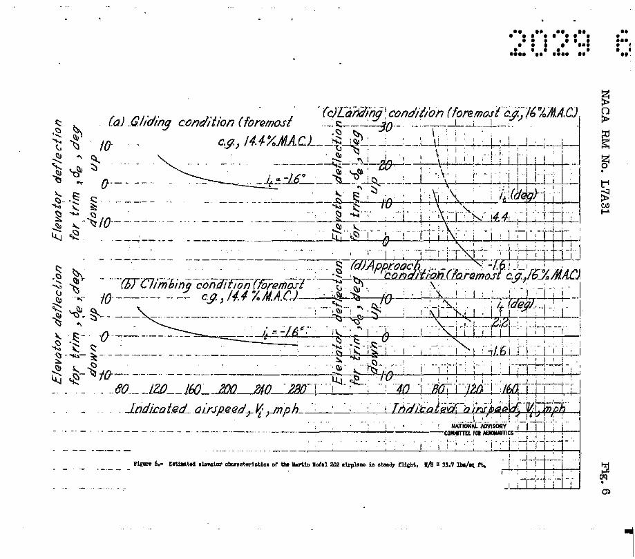
D-3 Elevator control power.- (1) It Will be possible to obtain steady-flight over the eqtire speed ranee for most of the required conditions. (See f'ig. 6.) The elevator control for stalling the airp.1/;!.ne .in the landing condition (at the foremost center of gravity),
10
however, becomes marg1na~w1 th the conteDqlleted flap tull down stabilizer setting of 4.4°. It the cruising stabilizer setting (-1.60 ) were used, ample elevator would be e.aileble. (S~e fig. 6(c).}
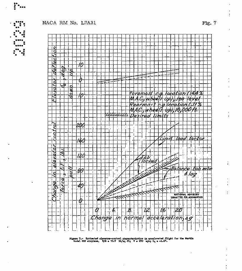
. (2) It should be no problem to obtain the positive limit load factor or max~um lift ooef~icient 1~ a tUrn in cruising flight conditions with the ;p:resen1j elevator, control (fig. 7). For 'turna in the landing cORdition lit .= 4.4°/1 however, the elevator available would probably ba inaufflc1ent to perfor.m the requirad maneuver at the foremost center of gt'Bv1 t:r through moat of the speed range in view of the aforamentioued marSinel control for stalling in steady fl~1; tn this sam& oo~1tion.
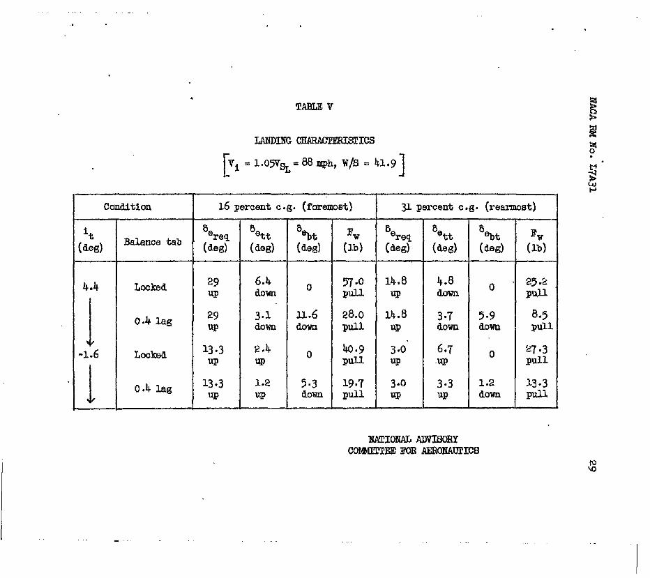
(3) The amount of'. e1.evfltor eathnated (trpm tests in the presence of a groundboa~d) to ~ ~~u1red to hold the a1rplane off the ground at a speed of 1.05Vst (68 Dile8 per hour, ~/s = 41.9) for various
arrensements 1s shown tn tt4 ble V.
It may be seen tbat the ele'\rstor control appears marginal for landing at the foremost center of' gravity for the contemplated prototype stabilizer setting of 4.40 • (MaXimum available up elevator is 300~ With the stabilizer set at -1.6° there is unques· tionably sufficient elevator for landIng throughout the center"ofgrevi ty range.
(5) Often B critical requirement for the adequacy of elevator control ia the ability of the control surface to raise the nose wheel during a take off at a sp~ed of 80 percent of Vst With the
center of gravity most forward.. No data were available, h.owever, with Which to estimate the take-off characteristics.
D-4 Elevator conyrol torces.· (l) and (2) Estimated characteristics in steady turning fliSht were computed for the most forward center-of-gravity location at sea level (a measure of' the maximum grad1ent) and With the center of grav! ty at the most rearward location for an altitudo of 10,000 feet (a measure of the minimum gradient).. For oach of these cond! tionB;, computatIons were made for the balance tab locked and a l1nked-balance-tab ratio of 0.4 lag (a linkage variation from 0.3 lead to 0.8 lag is provided for on the prototype airplane).
For all oonditions investlgate4 ohanges in normal e:ecel.eration will be apprOXimately proportional to the change in pilot applied control force. (See fig. 7.)
The ~adlentB ot elevator control force in steady turns at 270 miles p~ . hour, as estimated from data obtained With the model.
NACA RM No. L7A3~ .ll
in the cruising configuration, are much too hish in the tab ~ocked condition. Satisfactory gradients (between 20 and. 55 pounds per B,- references 8 or 9) are indicated, however,_ with a linked. balance tab ratio of 0.4 lag. Again, it must be stressed that minor changes in .Ch.a.t. and ChS could considerably change the estimated
characteristicE? • To illustrate this point computations were made to determine the effect of having sliently different hinge-moment parameters than were estimated. It was assumed that Cha.t and Ch8t
were changed by 0.0005 and 0115 WBS changed by -0.0005. Then, in
a turn at 270 miles per hour at sea level at the foremost center of grav! ty' the gradient is increased by about g1 pounds per,&-. for the 11nked-balance-tab ratio of 0.4 lag- On the other'hand, :i1' a spring tab system were reso:r:ted to, an increase of only 4 pounds per g would. be attained using a spring constant of e poUDds per degree tab deflection. Thus if a linked-baLance-tab arrangement can not be found which nil . be sa tisfactory for all condi tiona, a sui table spring ·tab or geared spring-tab' eystem would. probQbl.y' : furnish a satisfactory solution. -. .
(6) The control. forces required to hold the airplane off the groung.: at l.05VSL for two possible stabil.izer,settings and balance
arrangements with ,the airplane initially trimmed at l..4VSr, away from the ground are illustrated in table V«' It is seen that With 'a 0.4-lag balance tab the use of either the fixed or adjuBtab~e stabilizer would result in a wheel force lees than the limiting 50 pounds. .
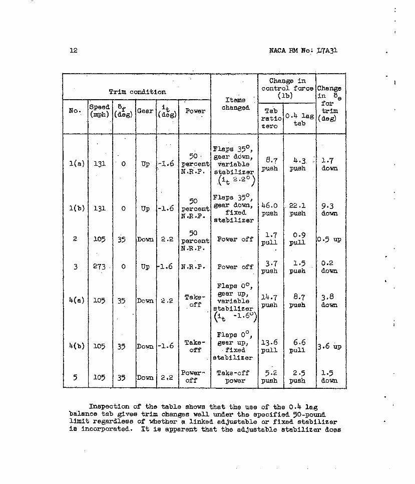
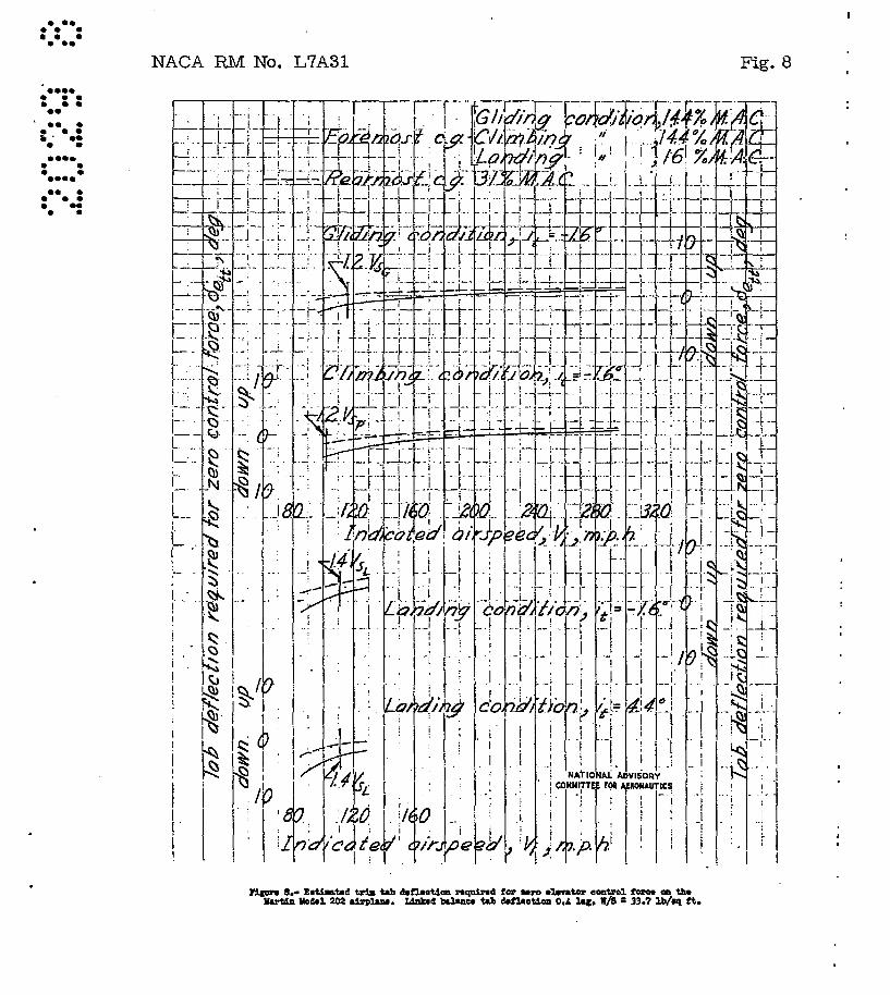
, ,D-6 Longitudinal trim changes. - As previously :mentioned the Martin ·.nPdei 202 has an adjUstable stabilizer 'liJ:lked to the flaps which moves when the flap is .,changed in a manner which was hoped to minimize the trim changes 'caused by flap deflection. The following table summarizes the estimated trim changes with a linked adjustable stabilizer as 'well aa for a fixed stabilizer {eet for 'trim in. cruising flight} •. rt shouid be noted: that a flap sett1D,s of 350 (approach) has been used in estimations requiring a landing setting (550 ) because of the insufficiency of the test data at the ~tter setting. The trim changes on the airplane caused by f~ flap deflection Will. therefore probably be somewhat different than the estimations indicate.
12
; Change in Trim concli tion control force Change
(lb) in 8e Items for No. Speed 8f Gear it Power changed Tab trim (mph) (deg) (deg) , . ratio 0.4 lag (deg)
zero tab
.. Flaps 35°,
50· gear down, 8·7 4.3, . '
1·7 lea) 131 0 Up '-:1;..6 ' per~ent variable ,.
, N.R oP. stabilizer push push down
'(it 2 0 2 0)
50 Flaps 350
,
l(b) 131 0 Up -J..6 percent gear down, 46.0 .22.1 9·3 N.R .P. fixed. push push down
stabilizer
50 J..7 0·9 0.5 up 2 105 35 Do'WIl 2.2 percent Power off pull pull N.R.P.
3 273 . 0 Up 1-1.6 N.R .P. Power off 3·7 1·5 . 0.2 push push down
Flaps 00 ,
Take- gear up, 24.7 8·7 3. 8 4(a) 105 35 Down "'::.2 off variable push push down stabilizer (it -J..6°)
Flaps 00,
4(b) 105 35 Down -1.6 Take- gear up, 13·6 6.6 3.6 up off . fixed pull pull stabilizer
5 105 35 Down 2.2 Power- Take-off 5·2 2·5 J..5 off power push :push down
Inspection of the table shows that the use of the 0.4 lag balance tab gives trim changes well under the specified 50-pound. limit regardless of whether ~ linked adjustable or fixed stabilizer 1s incorporated. It is apparent that the adjustable stabilizer doee
NACA EM No. L1A31 13
not always insure leee tr1i!l change than a fixed stabilizer .( oompare condi tions' 1 and 4). In fact 1 under certain comi tions the changes l)1ay be even greater with the adjustable stabi1izer. This consideration, the lack of information as to the magnitude of :trim changes with the flaps full down and, ~.addition, the ai'are- . mentioned marginal elevator control associated with the adjustable stabilizer probably would make it of prime interest to check the relative merits of a fixed and adjustable stabilizer on the first flying article. .
D-7 Longitudinal triInining device.- (2) .The 10ng1:tudina1 trimming device ia powerful enough to secUre zero elevator control forCeS over tne pe:p.ter-of-gravity range for the specified conditions.. (See fig. {3.) '.. .
Section E - Directional Stability and Control
E-l: Dynamic stabi1itY"- The rudder . fixed dynamic stabilitY' of the airplane was investigated for a crui~ing and a gliding fli~t condi tion. For the cruising condition . ( Vi :: 240 miles per. hour ) the airplane Will be spirally stable. The oscillatory stability' in this condition is such that the period of the oscillation will be about 3seconda and Will damp to 1/2 amplitude in somewhat lese than 1 cycle. In a gliding 'condi tion (Vi ::141 miles per hOur), however, the airplane Will be spirally unstable. But the epiral mode is such that the divergence will double in about 45 secoIids so that the pilot should have no difficulty in controlling it. The period of the oscillation in the gliding condition is about 5 seconds and is also rather heavily damped, the time to damp to half amplitude again being appreciably leee t~n 1 c.ycle.
E-2 Static directional stability.- (1) The airplane exhibits rudder fixed static directional stability for all flight conditione investigated. (See f:tg. 9.) It should be noted that the stability is high in the approach condition and particularly high in the landing condition. The angle of sideslip is roughly proportional to the rudder deflection from trim for all conditions.
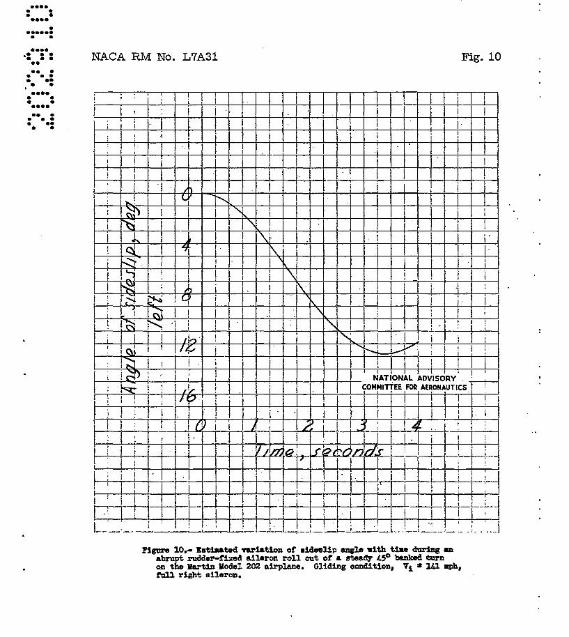
(2) The critical condition for sideslip caused byroll:tng i$ encountered in gliding fl.ighton the Martin MQdel 202 airplane. 'When gl.iding at Vi = ·141 miles per hour in a 450 banked turn, the rudder-fixed static directional stabi1it~ is such that the angle of sidesl.ip caused by full aileron deflection is only 12.80 which is . considerably leaa than. the permissible 20°" (See fig. 10.)
14 NACA BM No. L7A3l
(3) The rudder-force characteristics are such that with the rudder free the airplane will always tend to return to the trim condition with the Wings level. (See fig- 9.) Although there are no actual force reversals shown, there are tendencies toward over~ balance at the larger angles of sideslip. Moreover, overbalance may well occur on the airplane for some of these conditions if the basic limitations of the model hinge-moment data are considered. The date were insufficient, however, to establish whether or not rudder lock would occur at sideslip angles greater then 150
to 200 • If rudder lock is encountered on the airplane at the higher angles of Sideslip, it may be desirable to utilize a larger dorsal fin in order to a.el.iorate the deficiency. As Will. be pointed out later on in'"'the discussion calculations were made for only a spring tab system. With a linked-balance-tab arrans~ent or With a combination of the two arrangements even greater tendencies toward overbalancing would be encountered.
(4) The single-ensine condition investigated and referred to in this and subsequent sections pertaining to-asymmetric power conditione is for a climbing condition at a speed of about 1.2VBG'
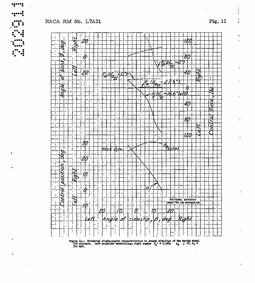
The thrust Simulated in the right engine (left propeller Windmilling) correspondt:id to about rated power at W/8 of 41.9. Althoush this condition is sometimes more stringent and at other times less stringent than those specified in references 7 to 9, similarity was generally close enough that the one condition investigated could be used throughout. The data were insufficient to establish whether or not the airplane could be balanced directionally in steady straight fligb.t for the aforementioned condi t10n with the rudder free and trim tab neutral. (See fig. 11.)
The amount of pitching moment resulting from sideslip althoush not mentioned in references 6 or 9 isgeneral~ considered to be of interest to airline, pIlots. This airplane Will probably meet requirement II-B of reference 22, for it is estimated that, for all conditions shown on figure 9, less than 10 elevator movement 1s needed tO,maintain longitudinal trim when the rudder ie moved 50 in either direction fram its trim position at zero bank.
E-3 Rudder control power.· (l) From the conditione investigated and shown in figure 9, it appears aafe to assume that the rudder will be suffiCiently powerful to trim the airplane 1n all probable steady symmetric flight conditione with the wings level.
(2) The only complete model yaw data available for the landing condition was at a 11ft coefficient corresponding to a speed of about 100 miles per hour- Using these data, it is estimated that,
NAOA RM No. L1A3~ 15
a landing at about eo iIi1les per hour in a cross-Wind at 16 m1~es per hour (20 percent VSr.) at 900 to the flight path would require
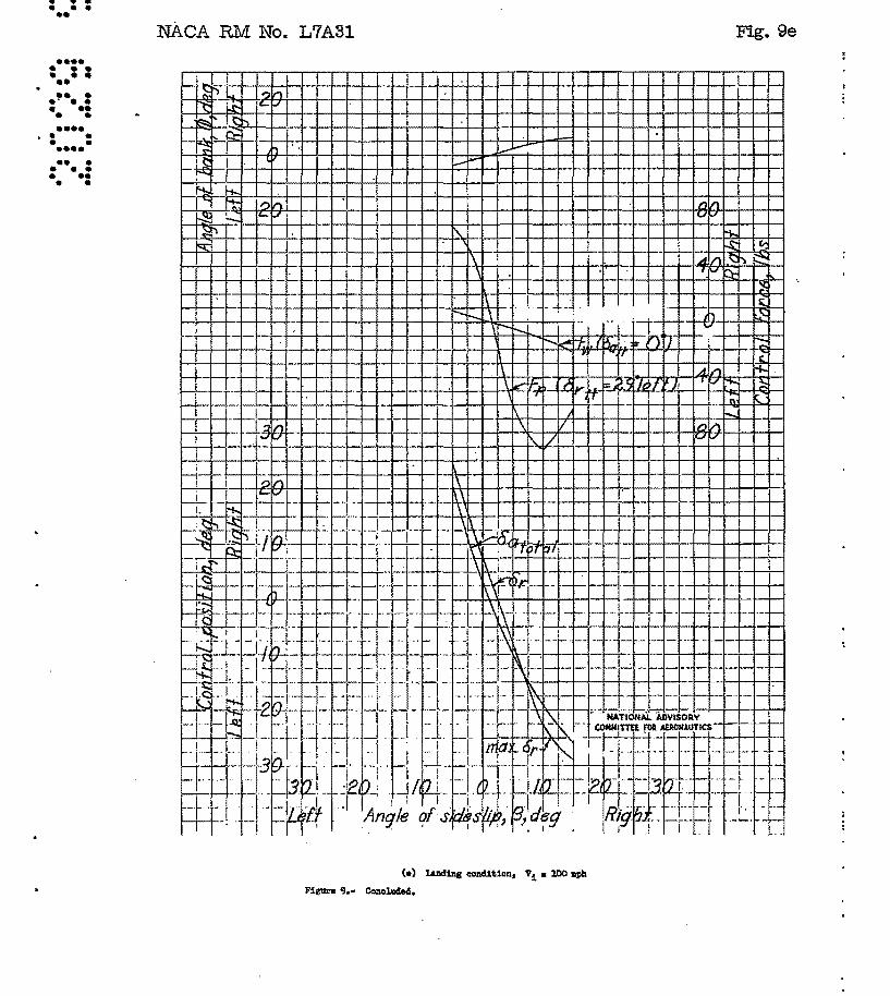
triIJl to be attainable at or; = 120 ~ideSlip. Jt can be seE?n, figure 9( e), that only about 60 left and 110 right .s1des~ip' can bj9 held.. with the contemplated maximum rudder deflection (:250 ). The trim$able Sideslip range could probably be increased by using less than the full down flap setting. (See fig. 9(d).) A slight increase would also be obtainable by increaSing the lli8ximuIli r1id~er throw to 1:300 , but the resulting increased severity of rudder. lock tendt9ncies might not warrj3nt the ch~ge. NO data were available With which to estimate the rudder control during take-offs.
(4) For the asymmetric power cond~tion investigated, figure 11, it is seen that about 220 right rudder is needE?d. to hold. zero sideslip. Rudder l$y not be ave.ilable to Illest the actu.9.l req'liirt9-ment- E-3-4, however, iilaelTlllch aE!' full take-off power was not simulated. Moreover, tile d;tre.ctional stability would be expe"Cted to be somewhat gr:-eater with the flaps in the take-off sett:1.ng (100 to 150 ). .
Application to OM requirements. - S~ficient rudder. control is probably available to execute 200 banked turns with or against the inoperative engine from a steady climb at a speed.of l.4V~
with maximum continuous power being applied to the operating engine. For although the thrust coeff'icient simulated in the model tests analyzed corresponded to only about rated power at 0L = 1.0 (w/s = 41.9) at the 0L for 1.4V~ (about 0.7) the
power represented wOuld be even greater than rated power for w/s = 33.7. .
No data were available for single engine operation in the approach condition, but because of the large directiohal stability, it is e~remely doubtful whether heaQ,ing changes of 150 against the inoperative engine could be achieved from trim with the wings levei.
(5) It is estimated that only about 4.50 of right rudder will be needed to overcome adverse ail.eron yaw during an abrupt full right aileron roll from a 450 banked turn in the gliding condition at L4VSQ.'
E-4 Budder pedal forces. - As has been previously mentioned, no particular' difficulty is expected to be encountered in obtaining satisfactory control forces because of the wide variety of linkage arrangements and springs of different strengths with which the
16 NACA EM No. L7A31
prototype airplane can be equipped. As an example calculations using one logical arrangement were msd~. This arrangement made use of en unpre10aded spring tab with a spring constant of 12 pounds per degree tab deflection.
(1) If the means suggested. are used to increase the trimmab1e Sideslip range, it is shown in figures 9(d) and 9(e) that the pedal forces will be considerably lees than 180 pounds for the required crose-wind. landing. Only about 20 pounds of rudder pedal force Will be reqUired to counteract the adverse aileron yaw in condition E"3-5.
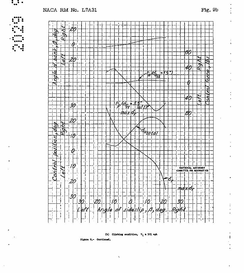
(2) The pedal force required to hold zero eideslip in the asymmetric pOWer condition inve~tisat~d was roughly 120 pounds with the trim tab set for Zero pedal force in the symmetriC climb condition. (See figs. 9(0) and 11.) The actual pedal force for the required condition would probably be somewhat larger as has been previously pointed out.
E-6 Directional trimming device.- (2) If a spring tab system is used on the rudder, soma thought should be given to the use of a separat~ tab :tor tr1mm1ng and balancing purposes. This is advisable because of the poSSib1lity of reduced tab effectiveness for balancing when most of the unsta1led lift range of the tab :I.s used up for trimming. Aleo in spring tab systems the teb hinge moments cauee the tab to blow back against the spring requiring extra effort on the part of the pilot_~n the. form of repeated trim jack adjustments. Because this airplane only attains· moCierat:ely high sp-e·ede and has not been designed for violent maneuvering} a combination spring and trim tab might be acceptable.
(3a) The directional trimming device is easily capable of reducing the rudder pedal force to zero in the gliding and climbing f1igAt conditions With the Wings level. (See figs. 9(b) and (c).)
(b) Ab'out 16.60 left tab (maximum deflection 200 ) is necessary to trim in the asymmetriC power condition investigated. Inasmuch as in this instance the required condition is slightly les8 savere, sufficient trim tab should be available to meet it.
Section F - Lateral Stability and Control
F-2 Static lateral stability.- (1) The airplane Will probably be laterally statically stable with both fixed or free ailerons in all flap-up conditions. (See figs. 9(a) tos(c).} However, because of the' effects of double-slotted flap daflection, considerable
NAOA:eM No. ~7A31 17
negative effective dihedral is lndic~ted in the computed approach and landing conditions (figs. 9(d), a~d 9~». 'The curves' of rollingmoment coefficient versus yaw angle fqr these latter conditions with the rudder fixed at 00 showed either a small amount of stability or neutral stability, but because of the hish directional stability present in these conditione and the large change in rolling moment with rudder deflection, the slope of the curve of total aileron deflection for trim against ~ indicates appreciable instability. It should be remembered that because of the limitations of the available data the flap-down estimates were made at speeds corresponding to angles of attack Which would be considerably lower than would. be normally used in the approach and landing conditions .. At these low angles of attack the flaps were stalled on the model casting same doubt on the" applicability of the data to the higher CL range or even the low C]:, . range at the hisher ~eynolds numbers of the airplane. Nevertheless, unless the rolling- and yawingmoment characteristics are much changed at the larger angles of att~ck, even the rudder-fixed dihedral effect will be negative l:>ecauee Of the greater adverse effect of power in the approach condition and because of the reduc,ed tail contribution to positive ' dihedral effect at the larger angles of attack in both the approach and landing condi tiona. If the dihedral effect indicated in figures 9( d) and5X e) persist on the airplane at the hisher lift coeffiCients, it is believed trouble may be encountered on several scores. In making instrument approaches at fairly low altitudes the pilot brackets a slender range leg, generally USing the rudder alone to accomplish this. The rate of spiral divergence would be hish and would. be continually initiated and aggravated by use of the rudd.er in obtaining and maintaining headings. In a final landing approach it would be possible to have the rudd.er fully deflected. when attempting to maintain a ground track while trying to raise a wing dropped by a gust. The pb/2.V available for leveling the wings in this condition would. give rolling velocities far below those now desired by airline pilots.
(2) The sma'll effective dihedral coupled. With a rather large directional stability insures that the roll1ngmoment caused by sideslip in a rudder-fixed aileron roll Will never be large enough to cause a reversal of rolling velocity because o~ aileron yaw.
{3) The variation of side force with angle of sideslip will be such that right bank aC90l!ipaniea risht steady sideslip and vice versa for aU conditions investigated. (See fig. 9.) "
F-3 Aileron control power.- (1) There are no d.1fferences between the Van Zelm ailerons used on the model 202 aPA co.p.ventional ailerons which would cause the airplane to rollln the wrong direction ~ediately after an abrupt aileron d~flect1on.
KAnA EM No. L1A31
(3) F.or all conditioll8 1nvest1sated., figure 12, the rolling velocity Will vary smoothly With aileron deflection and be approximately proportional to the amount of the d.eflection.
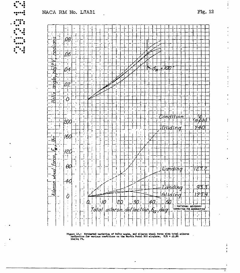
(4) The helix angle obtained with ma~mum aileron deflection will be approximately equal to or greater than the required pb/2V = 0.070 for all conditions except in the gliding flight cond.i tion at aapeed of 128 miles per hour (fig. 12) where a maximum value of pb/2V = 0.064 is obtainable. The values of pb/2V, however, were obtained fram the rolling-mament data of refe~ence 6 and contain an arbitrary correction factor of 20 percent to account for the effects of adverse yaw and wins tWist. This correction factor is believed to be conaer~ative ina~uch as the wing twist Will probably not be large at the speeds reached and the discussions of E-2-2 and F-2-2 indicate the adverse yaw effects will be··rather amall on this airplane.
(5) The value of pb will probably be considerably greater than 10' feet p~r .. ~ec·ond at 1.lVsx. when maximum. a11erondeflection is used.
(6) SuffiCient aileron control is available to secure lateral trim in the asymmetric power flight conditions investigated3 about two-thirds of the available aileron being required. (See f1g. 11.) Inasmuch as the ailerons remain effect! ve up to full throw; 1 t is probable that requirement F-3-6 could be met for any probable asymmetric power condition likely to be encountered flaps up.
(7) The ailerons are effective enousll to obtain a pb/ZV of 0.05 per 1000 of -wheel throw up to at le'ast a speed of 240 miles per hour ( approXimatel~. o.8vmax)' (See fig. Id.) .
F-4 AAI~r9n force8.- (1) The aileron control-force characteristiCS in rolling maneuvers and steady s:J.d.eslips sre not always of sufficient gradient to return the control to trim pOSition when cogniscence is taken of the allowable frictional limit of 6 pounds. (See figs. 9 and l~.) In fect, there is actual overbalancing indicated for an abrupt full roll in the gliding flight condition at the lower speed investigated (fig. 12).
(2) The estimated velue of o.8vmex in. level flight is approximately 240 miles Per hour. At this speed it would require a wheel force of' about 150 pounds, (fig. 12) to attain the required Pb/2V = 0.07. The force is considerably greater than the allowable 80 pounds. Moreover, because of' the overbalancing tendencies at the lower speeds, it does not appear feaSible to reduce the hlghspeed force by a change in the linke~ balance tab deflection rate.
• I
NAC1\. EM lio. L7.A.3l 19
Application to eM requ:i.remente. ':" :tn:rormatic;;h relative to CM rolling requirements can be gleaned from. the . !:Iection on streifgth requirements in reference 1. There it is stated that full aileron deflection is required only up to the design maneuvering speed (vp = approximately 170 miles per hour for this airPlane) and that when the design cruising speed is in excess of Vp the rate of roll required at the design cruiSing speed be not less than that obtained using full aileron deflection at Vp' Ass~ng a maximum. pb/2V of about 0.07 at Vp ' it is apparent that only a pb = 170 x 0.07 = 0.0495
2V 240 Will be required at 240 miles per hoUr. The control force required to obtain this pb/2V is about 95 pounds, (fig. 12) still over the So-pound limit, but possibly tolerable. Nevertheless, overbalancing is indicated at lower speeds and thus it was decided to investieate the characteristics with a spring-tab system.
Control forces and pb/2V were estimated for a spring-tab system with individual unpreloaded spring units with a spring strength of 2 pounds per degree tab deflection at zero aileron deflection •. Calculations were made for a spring tab the same size as the present linked tab and. for a spring tab of 50 percent increased effectiveness. Both tabs were assumed aerodynamically balanced with a deflection range of t15°. The cUrve of 8a veI"sus 8w sho'WIl in figure 4 was modified so that for tb.e same
maximutn. wheel deflection (1200 ) no reduction in maximum aileron deflection will be obtained when the spring tab is fully deflected. It can be seen, figure 13, that in the gliding condition at Vi = 240 miles per hour the wheel force for a pb/2V of 0.0495
is reduced to about 60 pounds with the tab of 50 percent increased effectiveness. Moreover, although in the gliding condition at Vi = 127 miles per hour there still ~xists a slight reduction in
control force for increased aileron deflection in the range of total deflections of between 220 and 350 , the objectionable overbalance has been eliminated,.. .
(3) The aileron control force for trim at zero sideslip in the aSyIllIllstric power flight condition investigated will be of the order of 20 pounds. This is far less than the limiting 80 pounds. (See fig. 11.)
E"-6 Lateral trimming devices. - (3a) The lateral tr~ng device Will be powerful enough to reduce the aileron force to zero in the gliding and. climbing conditions at all required speeds. (See figs. 9(b) and (c).)

20 NACA RM No. L7A31
(3b) Approximately maximum available trim tab (27.50) 'Will be
needed to reduce the aileron control force to zero at zero sideslip far the asymmetric power condition investigated. However, it should also be noted that the specific_condition outlined rcir F-6-3b should also be met inasmuch as it is of lees severity than tha,t shown. on figure 11. -
Section G - Stalling Characteristics
G-2 Stall warn1n§.- BeCause of differences in scale which will undoubtedly cause the stall characteristics to differ on the airplane and model, the discussion will be of a brief qualita'~ive nature baaed chiefly on the tUft studies and discussion of refer-ence 3. -.'
Good. atall warning Will be realized in the landing condition (ar = 550
) inasmuch as ·the root section unmistakably stalls firat. In the approach condition the stall also begins over the inbpsrd portion of the 'wing but spreads outboard over the ailerons more than in the landing condition. For the gliding condition (8f' = 00 )
the stall started at the inboard trailing edge and gradually .spread forward and outward. The addition of-power (8f' = 0 0 ) delayed the. stall in the nacelle region. For both flap-up conditions, a good portion ot the aileron region was stalled before CLmax was reached.
There generally Will be a fairly marked increase in the rearward travel of' the control column as stall approaches. (See fig. 6.) This is e.specially true in the landing condition.
G-3 Prevention of the complete stall.- The tuft sketches showed that a good portion of the ailerons ware stalled before CLmax' was
reached in the flap-up f-light conditions. The data of reference '6, however, indicate that considerable aileron effectiveness exists up to the stall •. In the landing condition, the ailerons remained UDstalled abo.ve the angle of attack for CLmax' As haa been shown previously, the available· elevator to stall with the stabilizer set in the flap-full-down position was marginal. However, for less positive stabilizer settings in the landing condition and in other conditions it should be possible to prevent or recover from the co~plete stall by the normal uao of the controls when corrective ection is taken immediately after the stall warning occurs.
G-4 Differential stalling of the wings.- Any differential stelling On the airpiane- will depend critically on the amount of
NACA EM No •• L7AJl 21
eay:mmet:ry in the actual airplane. Model date. ahoWe'd that in. flapdown. conditions the right wing panel stalled 'considerably earlier' than the left panel. It was also shown., however, that the stall occurred on the inboard portion of the wing so that the rolling or yawing moments incurred would probably be contro1lable*
CONCLTJDING BEMABKS
The results of the analysis based on the available wind-tunnel data indicate that tb.e Martin Model 202 airplane Will probably possesS satIsfactory handling qualities ~ all respects except possIbly in the fo1lowing. '
1. The amount of elevator control. available for landing or maneuvering in the landing condition is either marginal or :tnsuff1-cie~t when using the adjustable stabilizer linked to tb.e flaps. Moreover) indications are that tb.e longitudinal trim changes are neither larse nor appreciab~ worse With a fixed stabilizer than with the contemplated arrangement utilizing the adjustable stabilizer in an attempt to reduce the magnitude ,of the trim changes caused by flap deflection.
2. Indications are that the available rudder control Will enable landings to be made in cross Winds at 900 to the path of only 11 percent of the stalling velocity for some conditions. This condition could be improvedj chiefly by using somewhat less than full flap deflection.
3. Considerable nesative effective dihedral is probable in the landing and approach conditions which could make the airplane difficult if not dangerous to fly.
4. The aileron forces in abrupt rolls at cruising speeds are somewhat higher than the des1red limits. Moreover, at the lower speeds the a1leron forces are undesirably low or overbalancsd. No change in the linkage arrangement of the linked balancing tab would be likely to improve the control forces for one condition without having e detrimental effect on the other. However, a spring-tab

22 NACA EM No. L7A3l
a~eng~ent can be designed that will proVide reasonably satis-factory characteristios for ell conditions. .
Langley Memorial Aeronautical Laboratory National Advisory Committee for Aeronautics
Langley Field, Va.
Approved: /- . /
~A.- t.- Hartley A. Soule Ohief of Stability Research Division
eMIl
. . . I ./1 i'~~ 'I $.-4 '.f.,; ~
;. JO'aeph Weil Aeronautical Engineer
?/l a,I'F ,,-t-f 7. ~aA-Margaret F.' Spear EngineerIng Aide
. ,
. ,
NACA BM No. L7A3l
REFERENCES
1. Hess, Weiner F., and. CoughJ.in,t K .. J.: Wind Tunnel Results of Model 202 - First Series, 8.75i Scale ModeL Aero. Sec. Rep. No ~ 217, Tht;l Glenn L" Martin Co., March 1946.
23
2. Taylor, Robert D.: Wind. Tunnel Tests on' Glenn L. Martin Company Model M-202, Second Series. M.l.T. Wind Tunnel Rep~ No~ 714, Feb. 1946.
3. Cooper, I.. G.: Wind Tunnel Results of Model 202 Third Series Teste - 8.75; Model. Effect of Rutming Propellers. Aero. Sec. Rep. 'No. 225, The Glenn L. Martin Co.; March 1946.
4. Carell, Marguerite E.: Wind Tunnel Tests on Glenn L. Martin Company 'Model M"':'20'2, Fourth Series. M.l.T. Wind Tunnel Rep. No. T23, Feb. 1946r
5· Pope, A. 'Y.: 'Wind Tunnel Teste of the Model 20'2 Rudder" Georgia Tech. Rep. No. E-69, Daniel Guggenheim School:. of AeronautiCS, Feb. 1946.
6. Ducoffe, C. I.., Moseley, W. C., Jr., and Whitaker, Charles I.., Jr.: Wind Tunnel Tests of the Model 202 Aileron. Georgia Tech Rep. No. E-66, Daniel Guggenhaim School of AeronautiCS, Dec. 1945.
7. Anon~: Airplane Airworthiness -Transport Categories. pt. 04 of Civil Air Regulations, ,Civil Aero. Board, U. S. Dept. Commerce, Nov. 9, 1945.
8. Anon.: Specification for Stability and Control Characteristics of Airplanes. SR-119A, Bur. Aero., April 7, 1945.
9· Anon.: Stability and Control Characteristics of Airplanes. APJl' Specification No. R-18l5-A, April 7, 1945.
10. K'ayten, Gerald G.: Analysis of Wind-Tunnel Stability and Control Testa inTer.ma of Flying Qualities of Full-Scale Airplanes~ NACA ARB No. 3J22, 1943.
1L Zilmnerman, Charles H.: An Analysis of Lateral Stability in Power-Off Flight With Charts for Use in Design. NACA Rep. No. 589, 1937 ~
12. Swenson, Robert S., and Toll" Thomas A.: Estimation of Stick Forces from Wind-Tunnel Aileron Data.. NJ..CA ARB. No. 3J29, 1943.
24 NACA RM No. L7A31
13. Schuldenfrei, Marvin: Some Notes on the Determination of the Stick-Fixed Neutral Point from Wind-Tunne!.t Data. NACA RB No. 3120, 1943.
14. Swanson, Robert S., and Crandall, Stewart M.: Lifting-Surf'aceTheory Aspect-Ratio Corrections to the Lift and Hinge-Moment Parameters for Full-Span Elevators on Horizontal Tail Surfaces. NACA TN No. 1175, 1947.
15. Langley Research Department (Compiled by Thomas A. Toll): Summary of Lateral-Control Research. NACA TN No.. I 1947·
16. Crandall, stewart .N.} and Murray, Harry E.: Analysis of Available Data on the Effects of Tabs on Control-Surface Hinge Moments. NACA TN No. 1049, 1946.
17. Ribner, Herbert S.: Notes on the Propeller and Slipstream in Relati'oh to Stability. NACA ARB No. L4IJ2, 1944.
18. Pearson, Henry A., and Jones, Robert T.: Theoretical Sta bili ty and Control Charaoteristics of Wings With Various Amounts of Taper and TWist. NACA Rep. No. 635, 1938.
19. Bamber, Millard J.: Effect of Some Present -Day Airplane Design Trends on 'Requirements for Lateral Stab!l! ty. NACA TN No. 81I!-, 1941.
20. Swanson, Robert S., and Priddy, E. LaVerne: Lifting-SurfaceTheory, Values of the Damping in Roll and of the Parameter
, Used, in EstimatIng Aileron Stick Forcee. NACA ARB No L5F23, 1945·
21. Sivella, James C., and Deters, Owen J.: Jet-Boundary and PlanForm Corrections for Partial-Span Models With Reflection Plane, End Plate, or No End Plate in a Closed Ciroular Wind Tunnel. NACA TN No. 1077, 1946.
22. Gilruth, R. R.: Requirements for Satisfactory Flying Qualities of Airplanes. NACA ACR, April 1941.
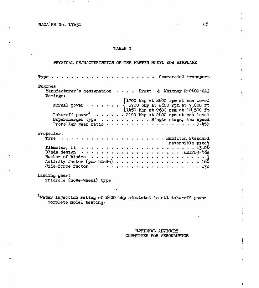
TABLE I
PHYSICAL CHARAorERIs.rrCS OF THE MARTIN MODEL 202 AIBPLANE
Type • • . . • . .. • . • a .. • , . . .. . . . . Commercial transport
Engines MBnufacturerts designation Ratings:
Normal power
Pratt & Whitney R-2€oO-CA3
•• 1700 bhp at 2600 rpm. at 7,000 ft {
1.100 bh.p at 2600 rIlDl at sea level
1450 bhp at 2600 rpm at 1.8,500 ft Take-off power). •• 2100 bhp at 2800 rpm at sea level. Supercharger type ••• • • Single stage, two speea Propeller gear ratio •••••••••••••••••• 0.450
Propeller: Type ..... ......
Diameter, ft Blade design Number of blades •• • • • • Activity factor (per blade) Side-force factor • • • • • • •
Landing gear: Tricycle (nose-wheel) type
• • • • t
. .
• Hamilton Standard reversible pitch
• • • • • 1.3·08 . . . • 2lil7B3 -48.R . 3 168 . . . • l.32
1 Water injection rating of 2400 bhp simulated in all. take-off power complete model testing.
NATIONAL ADVISORY COMM;l'laY.EE FOR AERONAurICS
NACA :eM No. L7A3~
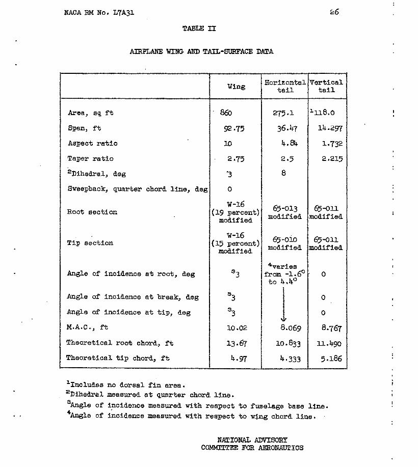
TABLE II
AIRPLANE WING AND TAIL-SUBFACE DATA
Area, sq ft
Span, ft
Aspect ratio
Taper ratio
2D1hed.ra~, deg
Wing
8Eo
92·75
10
2·15
'3
Horizonta~ Vertical tail tail
275.1 1ll8.0
36.47 ~4.297
4.84 1.732
2.5 2.215
8
Sweepback, quarter chord line, deg 0
Root section
Tip section
Angle of incidence at root, deg
Angle of incidence at break, deg
Angle of inCidence at tip, deg
M.A.C., ft
Theoretica~ root chord, ft
Theoretical tip chord, ft
1Includes no dorsal fin area.
w-16 (19 percent)
modified
65-0~3 65-011 modified modified
w-16 65-010 65-011 (15 percent) modified modified
modified
10.02
13·67
4·97
4.varies from-l.~' to 4.40
1 8.069
10.833
4.333
o
o
o
2Dihedra~ measured at quarter chord line. 3Angle of incidence measured with respect to fU6e~ge base line. ~Angle of i~cidence measured With respect to wtng chord line.
NATIONAL ADVISORY COMMITTEE FOR AERONAUTICS

TABLE ill
AIBPLANE COmOL-SOBFACE DATA
Aileron
Percent span 1}2 .2 Area, behind hinge line, aq ft 16.6 Balance area, sq it 4.32 Percent chord beh1.od. h1nge line 23·0 Mean chord, beh1nd hinge line, it 1.437 Distance to 1/4 taU M.A.C. fran
1/4 wing M.A,C' J it
Control deflect10n, deg 30 up 15 down
Trim-tab area, sq it 1·33 Span, it 4-Tab deflect1on, deg 12 up 16 down
Balance tab area, aq ft (2) Tab deflection, deg 9 up 12 dawn
10M Side ;Sama tab used for tr1m1ng and balancing
Flaps up 4 Flaps doWn (of'" 550) :Double slotted flaps Split flaps
Elevators Rudder WingS
Fuselage napas flaps
90 100 63·4 9·9 24·5 39·67 150 30 7·63 15·12
20.0 34.0 25·67 1.50 2.796
35·-'1-6 . 33·&; ~6 up 16 down 430 up 15 down 25 rignt 25 ~eft
3·43 3·93 7·1 6.50
:15 i20 (2) (2)
.8 lag .3 lead i10
Flap deflections, deS (corresponding powers)
For landinS • • • • • For take-off •••• Approach • • • • • • All other ooDdi tiona
NATIONAL ADVISORY COf«.U'lTEIil FOR Al!RONAUrICS
• • • 45-55 (power off) • .10-15 (2100~2400 hp) • . • • 30-35 (765 hp)
• • • Flaps retracted
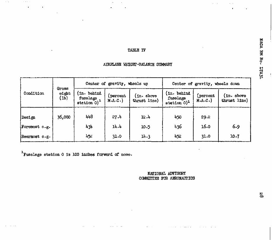
TABLE IV'
AIRl'IJINE WEIGHl' -BALANCE stJ1.!MARY
Center of grad ty, wheels up Center of ~avity, wheels down Gross
Condition eight (in. behind (percent (in. above (in. behind (percent (in. above (lb) fuselage 1 i'usela ge station 0) M.A.C. ) thrust line) station O}l M.A.C. ) thrust line)
Design 36,000 448 27·4 12.4 450 29·2
ForemoBt e.g. 434 14.4 10·5 436 16.0 6·9
HearmoBt e.g. 4']2 31.0 14·3 452 31.0 10·7
1 Fuselage station ° is 100 inches forward of nose.
NATIONiIL ADVISORY COMMlTl'EE FOR AEROIiAllrICS
Condition
it Balance tab (des)
4.4 Locked
1 0.4 lag
-1.6 Locked
1 0.4 lag
TABLE V
LANDING CILARAOfERISUCS
[Vi = 1.05Vsr. = 88 mph, w/S ::: 41.9 ]
16 percent e.g. (foremost) 31 percent c.g. (rear.most)
8 ereq 6 ett 8~t
(des) (des) (des)
29 6.4 0 up dOllll
29 3·1 ll.6 up down down
13·3 2.4 0 up up
13·3 1.2 5·3 up up down
Fw B Be 6~t ereq tt (lb) (deS) (deg) (deg)
57·0 14.8 4.8 0 pull up down
28.0 14.8 3·7 5·9 pull up down down
40·9 3·0 6.7 0 pull up -lIP
19·7 3·0 3·3 1.2 pull lIP up down
NATIONAL ADVISORY CQf.IIIlTTEE FOB AERONAUrICB
Fw (lb)
25·f:: pU;U
8·5 pull
:::7·3 pull
13·3 pull
.. . .. ~ ....... . • • • • .. . .' ... I - : :. • ••• •• •••• ••
Note: All dimensions In fQet
Section A~A
r-------7133-----"'i
FOfl!lfll()J/ (§ear v.
17.00 -..;
FlgurQ I . - Three' flew drawing 0/ t!le Marlin Model 20Z airplane,
•
·1 • •••
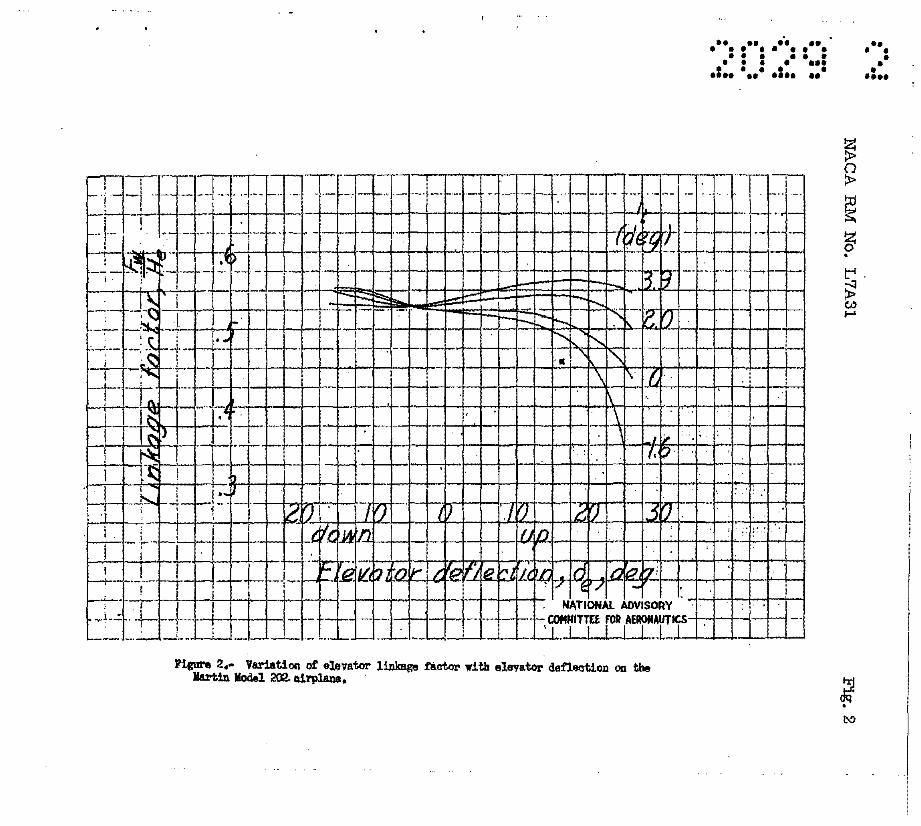
FiguN 2.- Variation of elevator link:Bge i'l!ator with elevator deflection on the IIal'tln lodel 202. airplane. '
•• •• •• •• • •• •• •• • ••• ••• • • • • ••• .: ••••••• :.. ee'
., • • • • • ••••
•• •• •• • • • • •
•••• 0: :: ", . •• • • •• • •• • • •••• • • • • •••• •• • • •• • •• • •
NACA RM No. L7A31 Fig. 3
i I .~ I I.~ ["-. . 0 I f ~ oj ! f· f"'\.
~ l/.~ j I I ~i !
I ; _-' I i I .. i -I
I I ;s I IlA 1
0
I I "
I : o!, I ; I r ! I : ! I 0 v·: •. ,; i .... i i j Ii' _____ -'--~_'___.-.... : ........:.'~~~._.J'"~ .. _.~ .• ~ __ ... _ ... ; ~~.' ..... J •••.• ~ .... i. -..ow ~ ......
Figure 3.- Variation of rudder linkage factor with rudder deflection on the Martin Model 202 airplane. Spring tab looked, no load.
• •••• • ••••
• • ••• • •• • •• •• •• • • •• •• •• • • ••••• • • • • •••• •• • • •• • •• • •
NACA RM No. L7A31
Figure 4.- Variation or alleroll l1nkase tact ..... wheel "ef'leoUOII. ane! linW balanoe tab c!et'hatiOll with eUeroa. c!erlection 011 the IlarUnl!odel 202 airplane.
Fig. 4

.. . .... ,.. .. . .' .. .. . ••• ••• • • • • ••• • • •• • .... '..... .... ..
~ .
. £l •
••••• • • •• • • • • •
•••••••••••••••• .': : .' ',,: ,:., ..... :.. ,,-
:3! OQ .
•• • ••• • • · , •••
1
•• • • • ••• •
•••• • •• · ... •• •• • • •• • ••
• • • •••• • • • • •••• •• • • •• • •• • •
NACA RIA No. L7A31
1---; f---+---1---+-·-f--I-+-l---I--+-I~-I-r--- -+-+-iH--+-+--t-+--+-+--ll- +-t--l-+--+-+ I I
I -it' t~
"'-..... f , ,
Fig. 7
1(.,
~ I I I--i--.<':I--+---f--!--+-+-I---I--I---+-+- 1--+-+.-+-+. -f- - --t-i-+--+-+-t--l-+--+-+-t--l-+--+--t-t--l-:-+--t--l
~ '" I ~ Ci )
'J ~
/:./
c:: ...;
'<. I ... ·l' ._.,... rr J ,"1- . ___ L~r/~~ 'hn.~r
I'1IUH '1.- Eat_ted .lna~tr.ol chaN.cteZ'ietloa 10 accelerated t11aht tor thII I!artiD l1a<!el :202 a11'plaDe. W/S. )).'1 lb/aq ttl V. 2'70 .pbl it • _1.6a •
• •• •• • •• • • ••
•••• • •• • •• •• , ... • •• ". -• • •••• • • • • •••• •• • • •• • •• • •
NACA RM No. L7A31
~I ...... 1 .. :::-.
t· ".~ .-I "' I ! I~ I r' i··~ I ~ ! I" 1 I \ ~:~"" ! ft.-::: I~ I" I I k~' I I;
! i~ I " .J.." '" . t 1_ I~ tV , ~ '~ I ' 1---
I
I I I r I
~ ~: I
1:'P:i I ".
Fig. 8

•••• • •• · ... ••
•••• • •• •••••• •• • • •• • •• • •
• • ••• • • • • •••• •• • • •• • •• • •
NACA RM No. L7A31 Fig. 9a
Ca) Ql1d1111 ccmd1tl1X1, Vi. l27.2 aph
fil"'" 9.- !.ti .... te4 atead7 814011lip char&cter1atiCI ~ the \Iarl1n Vo4eJ. ::!02. a.1rpl.ane. If/S • '13.7 u../~ ft.
• • • •• ••
•••• • •• • •• •• •• • • •• • •• • • •••• • • • • • •••• •• • • •• • •• • •
NACA RM No. L7A31 Fig. 9b
(b) CUI1b1loc cand! tion, V 1 = 101 .. pi!
Figure 9.- Cont.im.Ho4.
•••• • •• • •• ••
•••• •• •• • •• •• ••• • •• • •• • • •••• • • • • •••• •• • • •• ~ .. • •
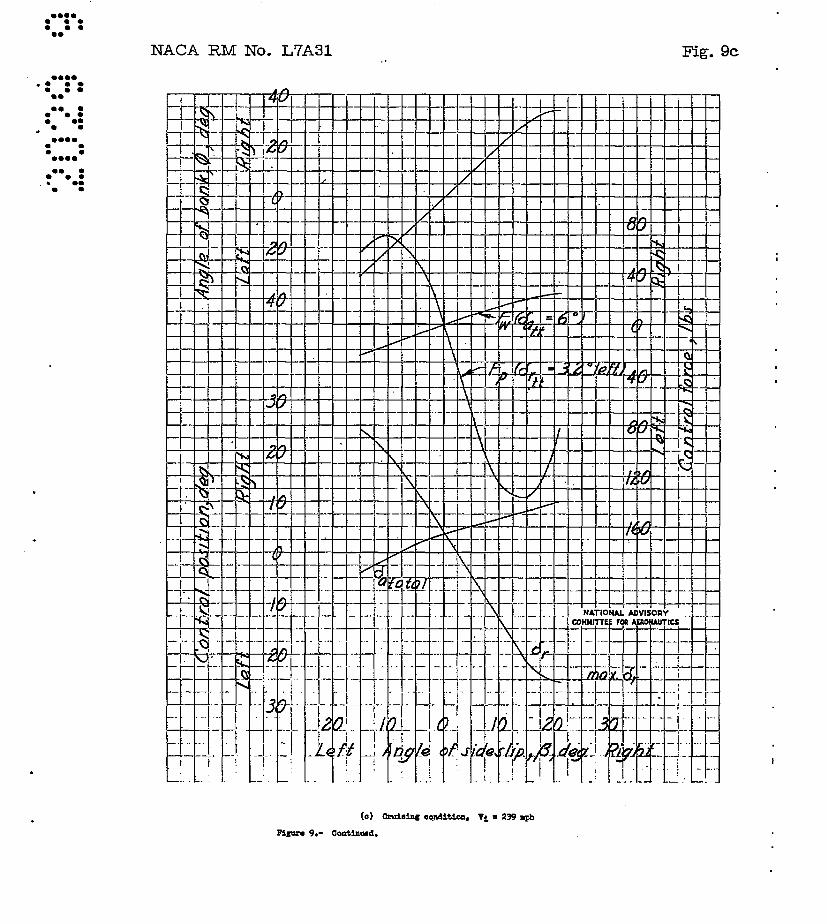
NACA RM No. L7A31 Fig. 9c
,., ~L 1_--HI4 ~~-+-+-H-+-++-l-f-+-+·-/-1--1-+-+-l--+-I--!:::-I-I-+-+-+--I-f-+-+-+-+-iT~!\ _ ~,...
h-~ - 1 --f-j-l-+--If--+-+-II-+-+--~I-+-f--f-II-+--JL-/-f-I'--I--+--I--/-+-1H--I-+--+-I-+-I ~ ~ I~~~~+~.~~+-~~.~~~~I~/~~~~++~~~++~M I--~--~. ~.;;11 !~~ --I--+--+--.j--I--l-+-+--+-+-~.j"_~-JI~/-+-I-.-I-l--l-4-~-I-+-t--I-+-I-+-~
, '-f-~ --I--I-+-+-,jIL....!/_-I--+-+-l--l-+-+-+-+-l--l-+-++-+-1--i f-r--~ I - 1-1--1--IL-i--+--+-+--I--l-+-I---+-...J.o1/"-.I---+--1--l1_-+-+-I-+-+-I--I-+-I-+-+-+--I--I-l f-t-~ c. j/
H-~~4-+-~-+~·+-+-~4-+-~4-~~/~~-+-+-+-+-~-I-+-+~-t--l--l-+~~~H-+-l--l-+~ ~f-+~+-1-4-+~-~~-+-I-.+-~~~~~~I--+~-I--I-4-+~I--+-+-4-4~1--+-I--II~V~-I~~-+-I-~
./ "\. t-I::: i
./ f\. In .~" I
1\ \
\
. !.-I 1---'--1--+--1-+-1-+1
_ ~ ; J ,
1--l'~-I-~+-~I~-~-I-~+-~-+-~+-+4-+-I-4-4-
(c) CruiaiIIC oO.l.d1t1ca, V1 .. :239 aph
F11UN 9.- CoAttnu.4.
-I-

• ••
•••• • •• • •• •• • •• • • •• •• •• • •
•••• • • .. ..... . •• • • •• •• • •
NACA RM No. L7A31
(d) Approub oODc!iUCII. Vi. ~ IIPh
1'1~ 9.- OCl>tim.1oId.
Fig.9d
i. , . -.................. - - -! I
-.-,
· ... • •• ••
•••• • •• • •• •• •• • •• • • • •• • • •••• •• • • • •••• •• • • •• • •• • •
meA RM No. L7A31
-+1 +~-I __ +~ ... J~'. .J _ -- --f-J+-+-+-..1- I. _1-'-1_ .......... 1--~"-+'£lH:!~;-/-:-+-+
(.) LaDo!Iinc condi t1cll. V:l.. 100 IIPh J'1e:Ure 9.- Co:lD1Ul!ed.
Fig. ge
l .
•••• • • • • •••• • •••••• • •
•••• . : :: •• •• • • •• • •• • • •••• • • • • •••• •• • • •• • •• • •
NACA RM No. L7A31 Fig. 10
,I i I ! ! I T Iii !
I I ! f" I I I I I i I
loot L l"--! I I ~ I '. r i i ~ I '\!! r
.l...! I I! \.~ I I i I , "
l
I:l. I! 1 !·I ~ : , I I ! ~ ), I i"i\ I I· i
1 ~ I! I '\" !
" '1\' " I I I • " r T T : I ' i I C:~_---+-I ~'--I_;-; -+--+-l~t-: -+--+-l-~+-+-- NATIONAL ADVISORY. -;-'~-l , kt- !' ,!,.. f i COMMlrnE FOA AE~ON~UTlCS.t
; t ; I : IC~· ! t l J ! I---'--r---I--'--
I iIi r I i I ; I il---,-t -+l-,-i-l-~!_i-----""+-!: o ......... LJ--i-I-rI_::-LJi-,:--I--+ .... L~~ll--+-L.:I-· iii 4. i : I :
i-~ -r-i -+1-11:--0-1-+, -t-~I!--i-+I-t--i-f!--+-' ·-i-,-t--i!!--f-l I: i +~:---:t-!-i -+--~or+'1 : I ilL i -+ I: ! i
" t i -r -1-+-+--I----lI-!--+-+-i -l I iii i +--~-r-::--
F1gare 10.- Bat1aated ft1"1atioD at aielel!llip angle with t1ae dur1Dg an abrupt rudde:r-t1xec! aileron roll out at & steadT 4~ banked &turn aD the Martin Kodel 202 airplane. Gliding oondition, Vi a 141 mph, f12ll. right aileron.
•••••• • • .. •••••• • • •••• • •• • •• • •• •• • • •• • •• • • •••• '. . • • •••• •• • • •• • •• • •
NACA RM No. L7A31 Fig. 11
•• • • •• • •• · " • •••••• • • •••• • •• ..... •• •• • • •• • •• • •
":. .... • • • • •••• •• • • •• • •• • •
NACA RM No. L7A31
I • . ' . ~.- ~ ~ : .
J~L. I t r
.. __ L ... .-.J. I I !.
.1 I , r
Fl1"" 12.- E,t1atat114 nriatiou of' helix &ll£la. ."., a1111rcm 1I'Mel f'croe 1I1th total. allirot> .den..Clti ... fOIl!' 'l"U'1a.J • ..-.lt1DDs Oil the Martin Pode1 202 a.trpla.M. 'Its .. a..ll6 lbs/eq ft..
Fig. 12

f .
... ~
, I
(
I