Embed Size (px)
Citation preview
-1- Revision 7/F3509
© Moffat Ltd, January 2009 E32 Convection Oven (Applies to units from S/N 40256)
SERVICE MANUAL
E32 CONVECTION OVEN
Applies to units from S/N 40256
-2- Revision 7/F3509
© Moffat Ltd, January 2009 E32 Convection Oven (Applies to units from S/N 40256)
WARNING: ALL INSTALLATION AND SERVICE REPAIR WORK MUST BE CARRIED OUT BY QUALIFIED PERSONS ONLY.
-3- Revision 7/F3509
© Moffat Ltd, January 2009 E32 Convection Oven (Applies to units from S/N 40256)
CONTENTS This manual is designed to take a more in depth look at the E32 convection oven for the purpose of making the unit more understandable to service people.
There are settings explained in this manual that should never require to be adjusted, but for completeness and those special cases where these settings are required to change, this manual gives a full explanation as to how, and what effects will result.
SECTION PAGE NO. 1. SPECIFICATIONS......................................................................................................... 5
2. INSTALLATION ............................................................................................................ 7 3. OPERATION.................................................................................................................. 10 3.1 Description of Controls 3.2 Explanation of Control System
4. MAINTENANCE............................................................................................................. 13 4.1 Cleaning 4.2 Routine Procedures
5. TROUBLE SHOOTING GUIDE ..................................................................................... 15
6. SERVICE PROCEDURES ............................................................................................. 18 6.1 Fault Diagnosis 6.2 Access 6.3 Replacement 6.4 Adjustment / Calibration
7. ELECTRICAL SCHEMATICS........................................................................................ 34
8. ELECTRICAL WIRING DIAGRAMS ............................................................................. 35
9. SPARE PARTS.............................................................................................................. 36
10. ACCESSORIES / OPTIONS.......................................................................................... 37
11. PARTS DIAGRAM ........................................................................................................ 38 11.1 Main Assembly 11.2 Control Panel Assembly
12. SERVICE CONTACTS.................................................................................................. 42
IMPORTANT: MAKING ALTERATIONS MAY VOID WARRANTIES AND APPROVALS.

-4- Revision 7/F3509
© Moffat Ltd, January 2009 E32 Convection Oven (Applies to units from S/N 40256)
-5- Revision 7/F3509
© Moffat Ltd, January 2009 E32 Convection Oven (Applies to units from S/N 40256)
FRONT
50
70
710
MWS
E1 280
WATER ENTRY
60
645
ELECTRICAL ENTRY
800
E1
MWS
E1 MWS
1. SPECIFICATIONS
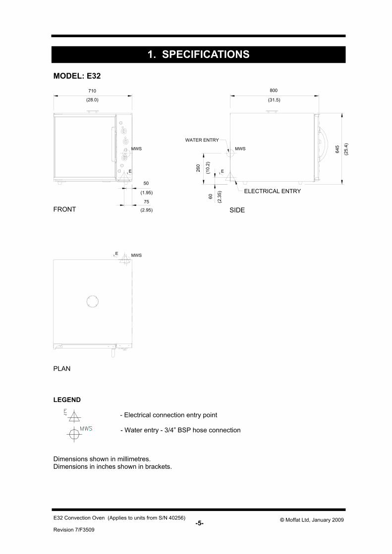
MODEL: E32
LEGEND
- Electrical connection entry point
- Water entry - 3/4” BSP hose connection
PLAN
Dimensions shown in millimetres. Dimensions in inches shown in brackets.
SIDE
(28.0)
710
(1.95)
50
75
(2.95)
800
(31.5)
645
(25.
4)
260
(10.
2)
60
(2.3
5)
-6- Revision 7/F3509
© Moffat Ltd, January 2009 E32 Convection Oven (Applies to units from S/N 40256)
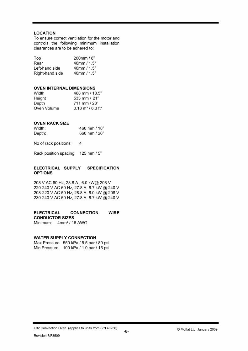
LOCATION To ensure correct ventilation for the motor and controls the following minimum installation clearances are to be adhered to: Top 200mm / 8” Rear 40mm / 1.5“ Left-hand side 40mm / 1.5” Right-hand side 40mm / 1.5” OVEN INTERNAL DIMENSIONS Width 468 mm / 18.5” Height 533 mm / 21” Depth 711 mm / 28” Oven Volume 0.18 m³ / 6.3 ft³ OVEN RACK SIZE Width: 460 mm / 18” Depth: 660 mm / 26” No of rack positions: 4 Rack position spacing: 125 mm / 5” ELECTRICAL SUPPLY SPECIFICATION OPTIONS 208 V AC 60 Hz, 28.8 A , 6.0 kW@ 208 V 220-240 V AC 60 Hz, 27.8 A, 6.7 kW @ 240 V 208-220 V AC 50 Hz, 28.8 A, 6.0 kW @ 208 V 230-240 V AC 50 Hz, 27.8 A, 6.7 kW @ 240 V ELECTRICAL CONNECTION WIRE CONDUCTOR SIZES Minimum: 4mm² / 16 AWG WATER SUPPLY CONNECTION Max Pressure 550 kPa / 5.5 bar / 80 psi Min Pressure 100 kPa / 1.0 bar / 15 psi
-7- Revision 7/F3509
© Moffat Ltd, January 2009 E32 Convection Oven (Applies to units from S/N 40256)
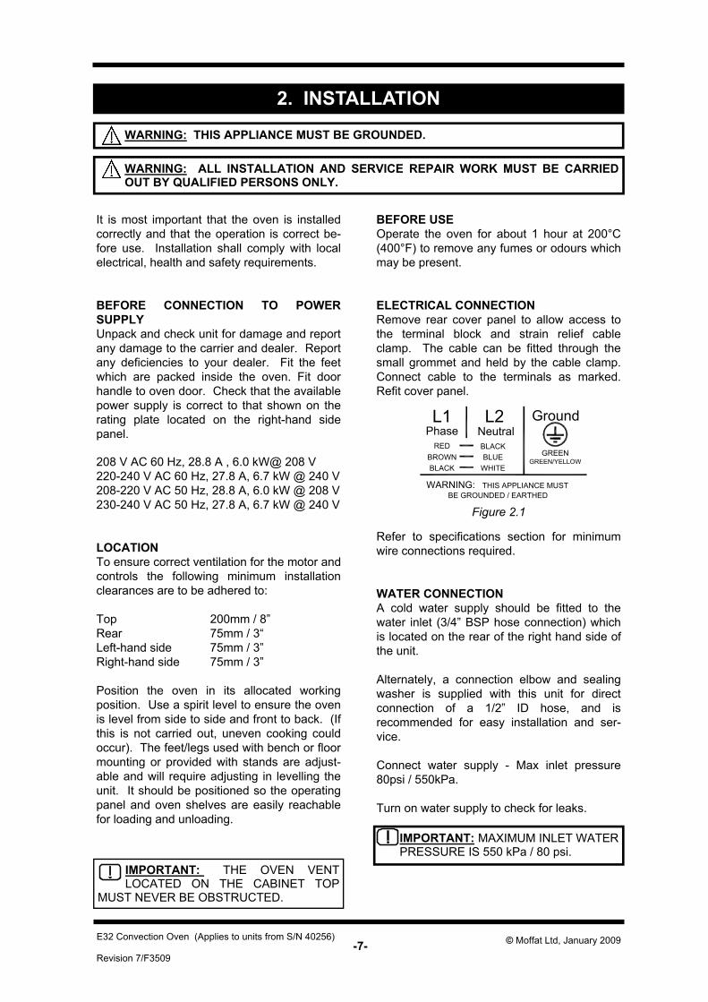
Refer to specifications section for minimum wire connections required. WATER CONNECTION A cold water supply should be fitted to the water inlet (3/4” BSP hose connection) which is located on the rear of the right hand side of the unit. Alternately, a connection elbow and sealing washer is supplied with this unit for direct connection of a 1/2” ID hose, and is recommended for easy installation and ser-vice. Connect water supply - Max inlet pressure 80psi / 550kPa. Turn on water supply to check for leaks.
It is most important that the oven is installed correctly and that the operation is correct be-fore use. Installation shall comply with local electrical, health and safety requirements. BEFORE CONNECTION TO POWER SUPPLY Unpack and check unit for damage and report any damage to the carrier and dealer. Report any deficiencies to your dealer. Fit the feet which are packed inside the oven. Fit door handle to oven door. Check that the available power supply is correct to that shown on the rating plate located on the right-hand side panel. 208 V AC 60 Hz, 28.8 A , 6.0 kW@ 208 V 220-240 V AC 60 Hz, 27.8 A, 6.7 kW @ 240 V 208-220 V AC 50 Hz, 28.8 A, 6.0 kW @ 208 V 230-240 V AC 50 Hz, 27.8 A, 6.7 kW @ 240 V LOCATION To ensure correct ventilation for the motor and controls the following minimum installation clearances are to be adhered to: Top 200mm / 8” Rear 75mm / 3“ Left-hand side 75mm / 3” Right-hand side 75mm / 3” Position the oven in its allocated working position. Use a spirit level to ensure the oven is level from side to side and front to back. (If this is not carried out, uneven cooking could occur). The feet/legs used with bench or floor mounting or provided with stands are adjust-able and will require adjusting in levelling the unit. It should be positioned so the operating panel and oven shelves are easily reachable for loading and unloading.
2. INSTALLATION
IMPORTANT: THE OVEN VENT LOCATED ON THE CABINET TOP
MUST NEVER BE OBSTRUCTED.
WARNING: THIS APPLIANCE MUST BE GROUNDED.
BEFORE USE Operate the oven for about 1 hour at 200°C (400°F) to remove any fumes or odours which may be present. ELECTRICAL CONNECTION Remove rear cover panel to allow access to the terminal block and strain relief cable clamp. The cable can be fitted through the small grommet and held by the cable clamp. Connect cable to the terminals as marked. Refit cover panel.
Figure 2.1
IMPORTANT: MAXIMUM INLET WATER PRESSURE IS 550 kPa / 80 psi.
WARNING: ALL INSTALLATION AND SERVICE REPAIR WORK MUST BE CARRIED OUT BY QUALIFIED PERSONS ONLY.
L1 L2 GroundPhase Neutral
REDBROWNBLACK
GREEN/YELLOWGREEN
WARNING: THIS APPLIANCE MUSTBE GROUNDED / EARTHED
BLACKBLUE
WHITE
-8- Revision 7/F3509
© Moffat Ltd, January 2009 E32 Convection Oven (Applies to units from S/N 40256)
1
3
2
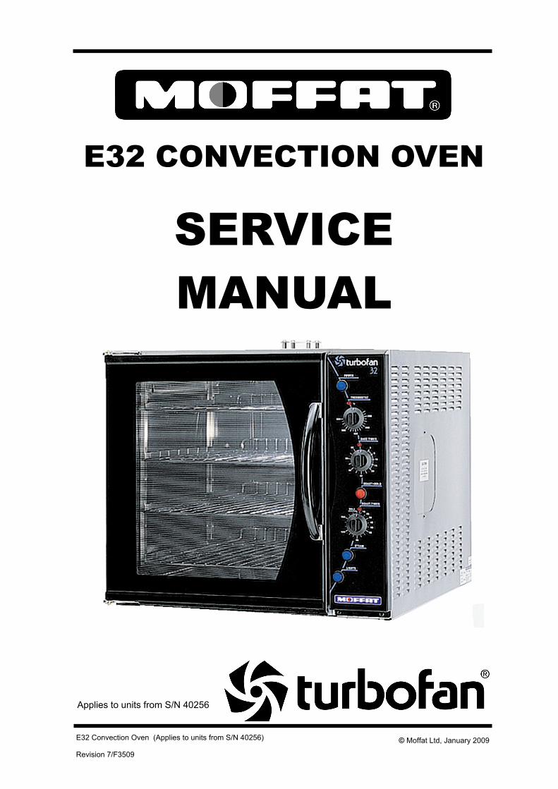
Figure 2.2
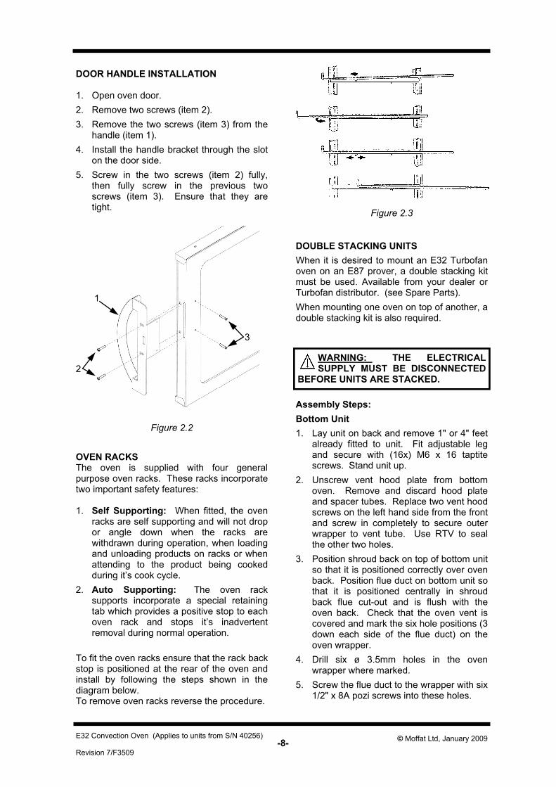
DOOR HANDLE INSTALLATION 1. Open oven door. 2. Remove two screws (item 2). 3. Remove the two screws (item 3) from the
handle (item 1). 4. Install the handle bracket through the slot
on the door side. 5. Screw in the two screws (item 2) fully,
then fully screw in the previous two screws (item 3). Ensure that they are tight.
OVEN RACKS The oven is supplied with four general purpose oven racks. These racks incorporate two important safety features: 1. Self Supporting: When fitted, the oven
racks are self supporting and will not drop or angle down when the racks are withdrawn during operation, when loading and unloading products on racks or when attending to the product being cooked during it’s cook cycle.
2. Auto Supporting: The oven rack supports incorporate a special retaining tab which provides a positive stop to each oven rack and stops it’s inadvertent removal during normal operation.
To fit the oven racks ensure that the rack back stop is positioned at the rear of the oven and install by following the steps shown in the diagram below. To remove oven racks reverse the procedure.
DOUBLE STACKING UNITS When it is desired to mount an E32 Turbofan oven on an E87 prover, a double stacking kit must be used. Available from your dealer or Turbofan distributor. (see Spare Parts). When mounting one oven on top of another, a double stacking kit is also required.
Figure 2.3
Assembly Steps: Bottom Unit 1. Lay unit on back and remove 1" or 4" feet
already fitted to unit. Fit adjustable leg and secure with (16x) M6 x 16 taptite screws. Stand unit up.
2. Unscrew vent hood plate from bottom oven. Remove and discard hood plate and spacer tubes. Replace two vent hood screws on the left hand side from the front and screw in completely to secure outer wrapper to vent tube. Use RTV to seal the other two holes.
3. Position shroud back on top of bottom unit so that it is positioned correctly over oven back. Position flue duct on bottom unit so that it is positioned centrally in shroud back flue cut-out and is flush with the oven back. Check that the oven vent is covered and mark the six hole positions (3 down each side of the flue duct) on the oven wrapper.
4. Drill six ø 3.5mm holes in the oven wrapper where marked.
5. Screw the flue duct to the wrapper with six 1/2" x 8A pozi screws into these holes.
WARNING: THE ELECTRICAL SUPPLY MUST BE DISCONNECTED
BEFORE UNITS ARE STACKED.
-9- Revision 7/F3509
© Moffat Ltd, January 2009 E32 Convection Oven (Applies to units from S/N 40256)
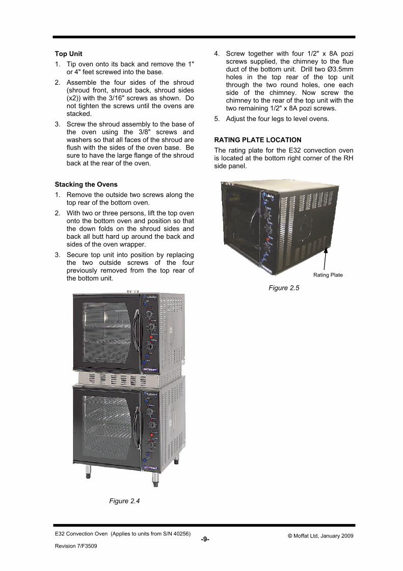
Rating Plate
Figure 2.5
Top Unit 1. Tip oven onto its back and remove the 1"
or 4" feet screwed into the base. 2. Assemble the four sides of the shroud
(shroud front, shroud back, shroud sides (x2)) with the 3/16" screws as shown. Do not tighten the screws until the ovens are stacked.
3. Screw the shroud assembly to the base of the oven using the 3/8" screws and washers so that all faces of the shroud are flush with the sides of the oven base. Be sure to have the large flange of the shroud back at the rear of the oven.
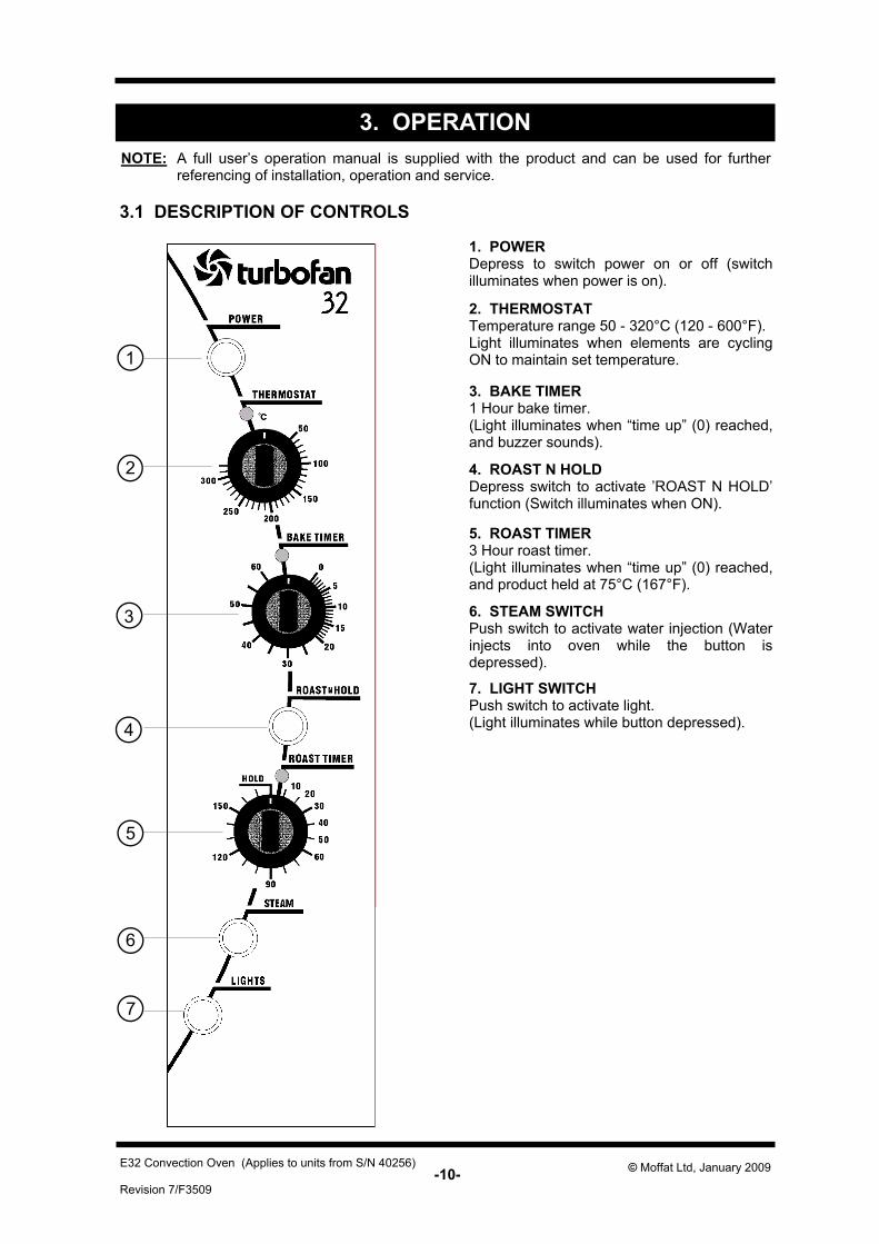
Stacking the Ovens 1. Remove the outside two screws along the
top rear of the bottom oven. 2. With two or three persons, lift the top oven
onto the bottom oven and position so that the down folds on the shroud sides and back all butt hard up around the back and sides of the oven wrapper.
3. Secure top unit into position by replacing the two outside screws of the four previously removed from the top rear of the bottom unit.
4. Screw together with four 1/2" x 8A pozi screws supplied, the chimney to the flue duct of the bottom unit. Drill two Ø3.5mm holes in the top rear of the top unit through the two round holes, one each side of the chimney. Now screw the chimney to the rear of the top unit with the two remaining 1/2" x 8A pozi screws.
5. Adjust the four legs to level ovens. RATING PLATE LOCATION The rating plate for the E32 convection oven is located at the bottom right corner of the RH side panel.
Figure 2.4
-10- Revision 7/F3509
© Moffat Ltd, January 2009 E32 Convection Oven (Applies to units from S/N 40256)
3.1 DESCRIPTION OF CONTROLS
2. THERMOSTAT Temperature range 50 - 320°C (120 - 600°F). Light illuminates when elements are cycling ON to maintain set temperature.
3. BAKE TIMER 1 Hour bake timer. (Light illuminates when “time up” (0) reached, and buzzer sounds).
6. STEAM SWITCH Push switch to activate water injection (Water injects into oven while the button is depressed).
1. POWER Depress to switch power on or off (switch illuminates when power is on).
5. ROAST TIMER 3 Hour roast timer. (Light illuminates when “time up” (0) reached, and product held at 75°C (167°F).
7. LIGHT SWITCH Push switch to activate light. (Light illuminates while button depressed).
4. ROAST N HOLD Depress switch to activate ’ROAST N HOLD’ function (Switch illuminates when ON).
3. OPERATION
7
6
5
4
1
2
3
NOTE: A full user’s operation manual is supplied with the product and can be used for further referencing of installation, operation and service.
-11- Revision 7/F3509
© Moffat Ltd, January 2009 E32 Convection Oven (Applies to units from S/N 40256)
3.2 EXPLANATION OF CONTROL SYSTEM
The E32 Turbofan convection oven features multi-function operator controls for which a correct understanding of their operation is required before carrying out any service or fault repair work. The control device functions are explained as follows: A power switch on the control panel isolates all to the controls of the oven. With the power switch Off all functions of the oven are inoperable. With the power switch On (illuminated) power is directly supplied to the 60 minute bake timer, steam (water injection) switch, door microswitch, light switch, and the temperature control circuit. The oven circulation fan will operate only when the thermostat is turned on. The control panel light switch will turn the oven lights on when the door is closed only when the light switch is held in. The oven lights will come on automatically when the door is open, as this is controlled by the door microswitch. The 60 minute timer is a mechanical timer and can therefore be operated with the oven’s power switch On or Off. However, only with the oven’s power switch On will the switch contacts of the 60 minute timer turn on the time-up buzzer and illuminate the time-up indicator on the control panel. The buzzer and time-up indicator provide indication that the time setting has run down to zero and at this point will remain On continuously until the 60 minute timer has been manually set back to the Off (vertical) position. The 60 minute timer does not control any other part of the oven’s operating system as this timer is independent of the temperature control and heating system. The steam (water injection) switch on the control panel can be operated whenever the power switch is On. The switch is momentary like the light switch and when depressed, will operate the electric solenoid valve at the rear of the oven and inject water across the elements and fan from the flat spray (vertical) nozzle positioned at the rear of the oven elements. Releasing the steam button will close the solenoid valve. This feature is used to instantaneously add steam into the oven. The temperature control of this oven is with a
capillary type thermostat which can be set to a required cooking temperature. The thermostat switch has a separate switch body assembled onto the front from the shaft assembly and when the thermostat is set to a cooking temperature, the switch contacts turn on the oven fan. The switch is closed (fan on) whenever the thermostat is not in the Off (vertical) position. The control panel indicator light above the thermostat knob cycles On and Off with the thermostat to indicate when the elements are on and the oven is heating. The E32 Turbofan convection oven has 6.5 kW of electric heating elements, comprising of a 3 kW inner coil, and a 3.5 kW outer coil, both of which make up the element assembly around the oven fan. The elements are switched on and off by the main oven thermostat or hold thermostat via a four-pole 25 Amp contactor located inside the control housing. Only two poles of the contactor are used, one for each element coil. The E32 Turbofan convection oven features a Roast-and-Hold system which can be used to automatically set the oven to a fixed holding temperature at the end of a timed cooking period. When the Roast-and-Hold switch is turned On the switch will illuminate and switch on a relay found inside the control panel, at the base of the control housing next to the door microswitch. When the relay is switched ON a normally closed switch pole on the relay is opened and the normal power supply to the oven thermostat is isolated. A second normally open switch pole is closed and this provides power to the 3 hour roast timer. If the roast timer is in the Hold (vertical) position the timer switch contacts will be in their normally closed position and supply power directly to the Hold thermostat located behind the control panel. The Hold thermostat is factory set to 75°C (167°F) and will supply power to the heating elements through the heating contactor as required to maintain its preset temperature. The thermostat heating light will also cycle On/Off as the Hold thermostat maintains temperature. In the Roast-and Hold mode the 3 hour timer can be set to a selected roasting time. During this time period the normally open switch contacts of the timer are closed. The timer has two change over switches and in this
-12- Revision 7/F3509
© Moffat Ltd, January 2009 E32 Convection Oven (Applies to units from S/N 40256)
position one is used to supply power to its timing motor and the other is used to switch power directly to the main oven thermostat. During the 3 hour timer run-down period the oven temperature will be controlled by the main oven thermostat to the set temperature and operate as previously described. When the 3 hour timer has run down and reached the Hold position the two switch contacts change over to their normally closed position which isolates power from the timer motor and the oven thermostat. It also switches power back to the oven hold thermostat. At this point the temperature control is now maintained by the hold thermostat as previously described. To cancel the hold circuit the Roast-and-Hold switch is turned Off. This turns off the contactor which removes power from the 3 hour timer and closes the contactor pole on the contactor that feeds the main oven thermostat. The Hold indicator light above the 3 Hour timer will illuminate whenever the oven is operating in hold mode (Roast ‘n Hold se-lected, and 3 Hour timer at zero position). The factory preset hold thermostat can be adjusted as required to change the holding temperature if necessary. Refer Service section for this procedure. The following Troubleshooting Guide should be used to identify any incorrect oven operation. On correct identification of the operating fault the Troubleshooting Guide will make reference to the corrective action required, or refer to the Fault Diagnosis section and/or Service section to assist in correction of the fault.
-13- Revision 7/F3509
© Moffat Ltd, January 2009 E32 Convection Oven (Applies to units from S/N 40256)
IMPORTANT: THIS UNIT IS NOT WATER PROOF.
DO NOT USE A WATER JET SPRAY TO CLEAN INTERIOR OR EXTERIOR OF THIS UNIT.
WARNING: ALWAYS TURN THE POWER SUPPLY OFF BEFORE CLEANING.
EXTERIOR Clean with a good quality stainless steel cleaning compound. Harsh abrasive cleaners may damage the surface. INTERIOR Ensure that the oven chamber is cool. Do not use wire brushes, steel wool or other abrasive materials. Clean the oven regularly with a good quality oven cleaner. Take care not to damage the fan or the tube at the right side of the oven which controls the thermostat. OVEN RACKS To remove, slide out to the stop position, raise the front edge up, and lift out. SIDE RACKS To remove, lift front top to disengage and slide rack forward. To replace, slide top rear slot in rack onto rear stud, then engage front keyhole on front stud. LAMP GLASS To remove glasses, unscrew anti-clockwise. To replace, screw in clockwise.
OVEN SEALS To remove, hold at their centre point and pull forward until they unclip. Remove side seals first, then top and bottom. The seals may be
4. MAINTENANCE
washed in the sink, but take care not to cut or damage them. To replace, ensure that the lip is facing the oven opening. Fit the top and bottom seals first, then the side seals. OVEN DOOR GLASS Clean with conventional glass cleaners.
IMPORTANT: DO NOT OVER TIGHTEN LAMP GLASS.
4.1 CLEANING
WARNING: ALL INSTALLATION AND SERVICE REPAIR WORK MUST BE CARRIED OUT BY QUALIFIED PERSONS ONLY.
-14- Revision 7/F3509
© Moffat Ltd, January 2009 E32 Convection Oven (Applies to units from S/N 40256)
4.2 ROUTINE PROCEDURES
PROCEDURE INTERVAL
DOOR SEALS Check for deterioration. 12 months
DOOR PIVOT BUSHES Check for wear. 12 months
DOOR CATCH Ensure that catch is adjusted such that the door closes properly.
12 months
ELEMENT Check that element resistance is correct to it’s rating (refer 6.3.15).
12 months
WATER NOZZLE Check for liming in water nozzle. 12 months
-15- Revision 7/F3509
© Moffat Ltd, January 2009 E32 Convection Oven (Applies to units from S/N 40256)
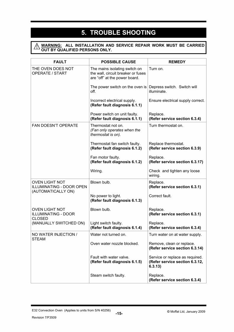
5. TROUBLE SHOOTING
FAULT POSSIBLE CAUSE REMEDY THE OVEN DOES NOT OPERATE / START
The mains isolating switch on the wall, circuit breaker or fuses are “off” at the power board. The power switch on the oven is off. Incorrect electrical supply. (Refer fault diagnosis 6.1.1) Power switch on unit faulty. (Refer fault diagnosis 6.1.1)
Turn on. Depress switch. Switch will illuminate. Ensure electrical supply correct. Replace. (Refer service section 6.3.4)
FAN DOESN’T OPERATE Thermostat not on. (Fan only operates when the thermostat is on). Thermostat fan switch faulty. (Refer fault diagnosis 6.1.2) Fan motor faulty. (Refer fault diagnosis 6.1.2) Wiring.
Turn thermostat on. Replace thermostat. (Refer service section 6.3.9) Replace. (Refer service section 6.3.17) Check and tighten any loose wiring.
OVEN LIGHT NOT ILLUMINATING - DOOR OPEN (AUTOMATICALLY ON) OVEN LIGHT NOT ILLUMINATING - DOOR CLOSED (MANUALLY SWITCHED ON)
Blown bulb. No power to light. (Refer fault diagnosis 6.1.3) Blown bulb. Light switch faulty. (Refer fault diagnosis 6.1.4)
Replace. (Refer service section 6.3.1) Correct fault. Replace. (Refer service section 6.3.1) Replace. (Refer service section 6.3.4)
NO WATER INJECTION / STEAM
Water not turned on. Oven water nozzle blocked. Fault with water valve. (Refer fault diagnosis 6.1.5) Steam switch faulty.
Turn water on at water supply. Remove, clean or replace. (Refer service section 6.3.14) Service or replace as required. (Refer service section 6.3.12, 6.3.13) Replace. (Refer service section 6.3.4)
WARNING: ALL INSTALLATION AND SERVICE REPAIR WORK MUST BE CARRIED OUT BY QUALIFIED PERSONS ONLY.
-16- Revision 7/F3509
© Moffat Ltd, January 2009 E32 Convection Oven (Applies to units from S/N 40256)
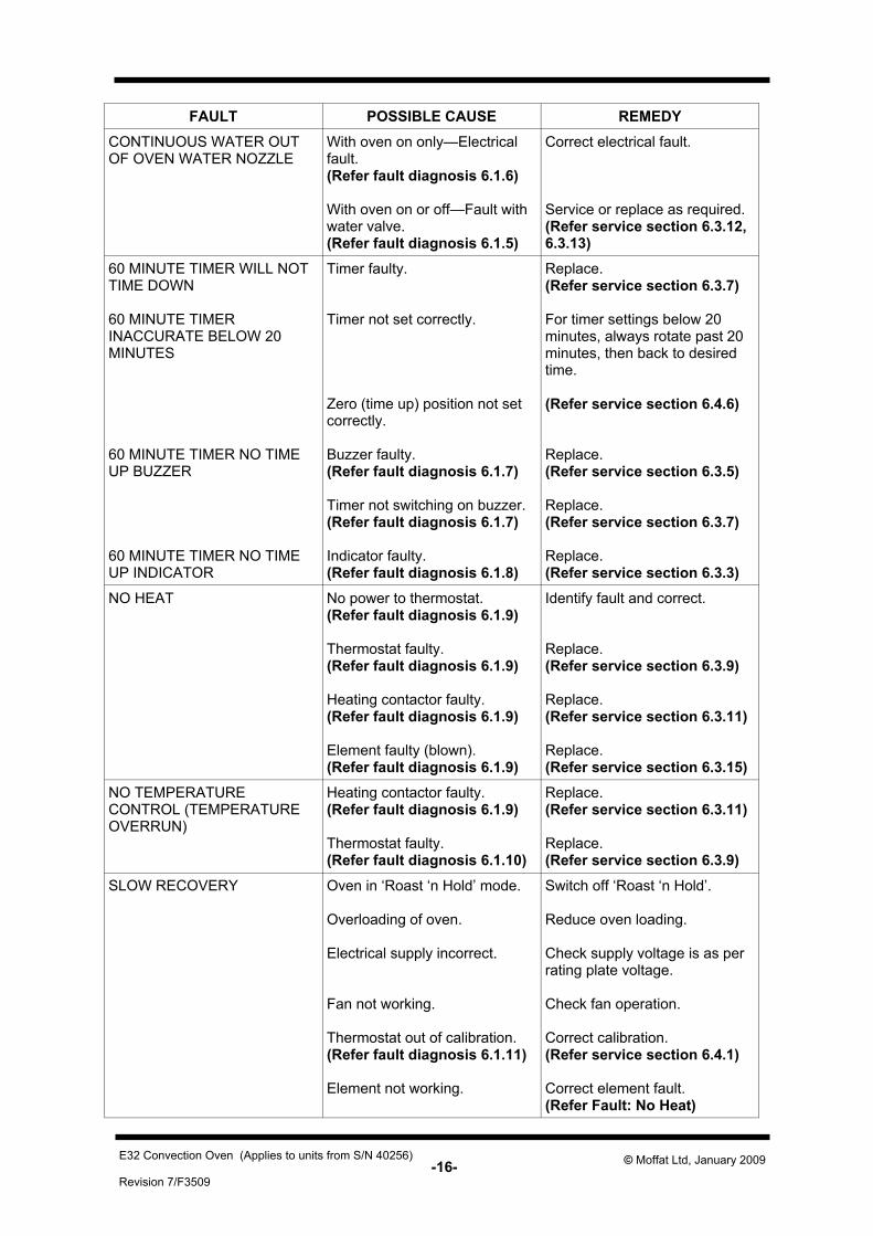
FAULT POSSIBLE CAUSE REMEDY CONTINUOUS WATER OUT OF OVEN WATER NOZZLE
With oven on only—Electrical fault. (Refer fault diagnosis 6.1.6) With oven on or off—Fault with water valve. (Refer fault diagnosis 6.1.5)
Correct electrical fault. Service or replace as required. (Refer service section 6.3.12, 6.3.13)
60 MINUTE TIMER WILL NOT TIME DOWN 60 MINUTE TIMER INACCURATE BELOW 20 MINUTES 60 MINUTE TIMER NO TIME UP BUZZER 60 MINUTE TIMER NO TIME UP INDICATOR
Timer faulty. Timer not set correctly. Zero (time up) position not set correctly. Buzzer faulty. (Refer fault diagnosis 6.1.7) Timer not switching on buzzer. (Refer fault diagnosis 6.1.7) Indicator faulty. (Refer fault diagnosis 6.1.8)
Replace. (Refer service section 6.3.7) For timer settings below 20 minutes, always rotate past 20 minutes, then back to desired time. (Refer service section 6.4.6) Replace. (Refer service section 6.3.5) Replace. (Refer service section 6.3.7) Replace. (Refer service section 6.3.3)
NO HEAT No power to thermostat. (Refer fault diagnosis 6.1.9) Thermostat faulty. (Refer fault diagnosis 6.1.9) Heating contactor faulty. (Refer fault diagnosis 6.1.9) Element faulty (blown). (Refer fault diagnosis 6.1.9)
Identify fault and correct. Replace. (Refer service section 6.3.9) Replace. (Refer service section 6.3.11) Replace. (Refer service section 6.3.15)
NO TEMPERATURE CONTROL (TEMPERATURE OVERRUN)
Heating contactor faulty. (Refer fault diagnosis 6.1.9) Thermostat faulty. (Refer fault diagnosis 6.1.10)
Replace. (Refer service section 6.3.11) Replace. (Refer service section 6.3.9)
SLOW RECOVERY Oven in ‘Roast ‘n Hold’ mode. Overloading of oven. Electrical supply incorrect. Fan not working. Thermostat out of calibration. (Refer fault diagnosis 6.1.11) Element not working.
Switch off ‘Roast ‘n Hold’. Reduce oven loading. Check supply voltage is as per rating plate voltage. Check fan operation. Correct calibration. (Refer service section 6.4.1) Correct element fault. (Refer Fault: No Heat)
-17- Revision 7/F3509
© Moffat Ltd, January 2009 E32 Convection Oven (Applies to units from S/N 40256)
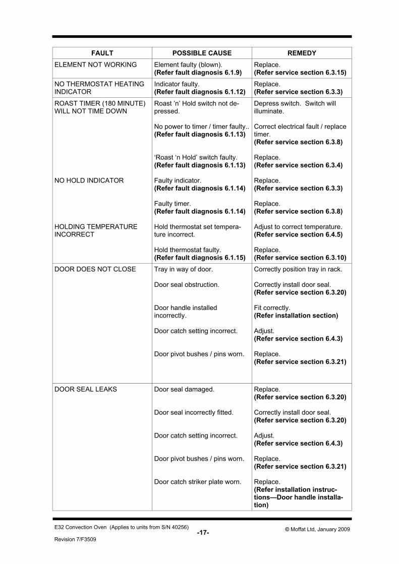
FAULT POSSIBLE CAUSE REMEDY
ELEMENT NOT WORKING Element faulty (blown). (Refer fault diagnosis 6.1.9)
Replace. (Refer service section 6.3.15)
NO THERMOSTAT HEATING INDICATOR
Indicator faulty. (Refer fault diagnosis 6.1.12)
Replace. (Refer service section 6.3.3)
ROAST TIMER (180 MINUTE) WILL NOT TIME DOWN NO HOLD INDICATOR HOLDING TEMPERATURE INCORRECT
Roast ’n’ Hold switch not de-pressed. No power to timer / timer faulty.. (Refer fault diagnosis 6.1.13) ‘Roast ‘n Hold’ switch faulty. (Refer fault diagnosis 6.1.13) Faulty indicator. (Refer fault diagnosis 6.1.14) Faulty timer. (Refer fault diagnosis 6.1.14) Hold thermostat set tempera-ture incorrect. Hold thermostat faulty. (Refer fault diagnosis 6.1.15)
Depress switch. Switch will illuminate. Correct electrical fault / replace timer. (Refer service section 6.3.8) Replace. (Refer service section 6.3.4) Replace. (Refer service section 6.3.3) Replace. (Refer service section 6.3.8) Adjust to correct temperature. (Refer service section 6.4.5) Replace. (Refer service section 6.3.10)
DOOR DOES NOT CLOSE Tray in way of door. Door seal obstruction. Door handle installed incorrectly. Door catch setting incorrect. Door pivot bushes / pins worn.
Correctly position tray in rack. Correctly install door seal. (Refer service section 6.3.20) Fit correctly. (Refer installation section) Adjust. (Refer service section 6.4.3) Replace. (Refer service section 6.3.21)
DOOR SEAL LEAKS
Door seal damaged. Door seal incorrectly fitted. Door catch setting incorrect. Door pivot bushes / pins worn. Door catch striker plate worn.
Replace. (Refer service section 6.3.20) Correctly install door seal. (Refer service section 6.3.20) Adjust. (Refer service section 6.4.3) Replace. (Refer service section 6.3.21) Replace. (Refer installation instruc-tions—Door handle installa-tion)
-18- Revision 7/F3509
© Moffat Ltd, January 2009 E32 Convection Oven (Applies to units from S/N 40256)
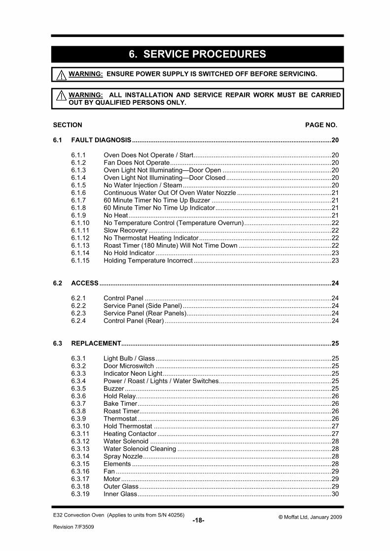
SECTION PAGE NO. 6.1 FAULT DIAGNOSIS..............................................................................................................20 6.1.1 Oven Does Not Operate / Start............................................................................20 6.1.2 Fan Does Not Operate.........................................................................................20 6.1.3 Oven Light Not Illuminating—Door Open ............................................................20 6.1.4 Oven Light Not Illuminating—Door Closed..........................................................20 6.1.5 No Water Injection / Steam..................................................................................20 6.1.6 Continuous Water Out Of Oven Water Nozzle ....................................................21 6.1.7 60 Minute Timer No Time Up Buzzer ..................................................................21 6.1.8 60 Minute Timer No Time Up Indicator................................................................21 6.1.9 No Heat................................................................................................................21 6.1.10 No Temperature Control (Temperature Overrun)................................................22 6.1.11 Slow Recovery .....................................................................................................22 6.1.12 No Thermostat Heating Indicator.........................................................................22 6.1.13 Roast Timer (180 Minute) Will Not Time Down ...................................................22 6.1.14 No Hold Indicator .................................................................................................23 6.1.15 Holding Temperature Incorrect ............................................................................23 6.2 ACCESS ................................................................................................................................24 6.2.1 Control Panel .......................................................................................................24 6.2.2 Service Panel (Side Panel) ..................................................................................24 6.2.3 Service Panel (Rear Panels)................................................................................24 6.2.4 Control Panel (Rear) ............................................................................................24 6.3 REPLACEMENT....................................................................................................................25 6.3.1 Light Bulb / Glass.................................................................................................25 6.3.2 Door Microswitch .................................................................................................25 6.3.3 Indicator Neon Light.............................................................................................25 6.3.4 Power / Roast / Lights / Water Switches..............................................................25 6.3.5 Buzzer ..................................................................................................................25 6.3.6 Hold Relay............................................................................................................26 6.3.7 Bake Timer...........................................................................................................26 6.3.8 Roast Timer..........................................................................................................26 6.3.9 Thermostat ...........................................................................................................26 6.3.10 Hold Thermostat ..................................................................................................27 6.3.11 Heating Contactor ................................................................................................27 6.3.12 Water Solenoid ....................................................................................................28 6.3.13 Water Solenoid Cleaning .....................................................................................28 6.3.14 Spray Nozzle........................................................................................................28 6.3.15 Elements ..............................................................................................................28 6.3.16 Fan .......................................................................................................................29 6.3.17 Motor ....................................................................................................................29 6.3.18 Outer Glass ..........................................................................................................29 6.3.19 Inner Glass...........................................................................................................30
WARNING: ENSURE POWER SUPPLY IS SWITCHED OFF BEFORE SERVICING.
6. SERVICE PROCEDURES
WARNING: ALL INSTALLATION AND SERVICE REPAIR WORK MUST BE CARRIED OUT BY QUALIFIED PERSONS ONLY.
-19- Revision 7/F3509
© Moffat Ltd, January 2009 E32 Convection Oven (Applies to units from S/N 40256)
6.3.20 Door Seals ...........................................................................................................30 6.3.21 Door Pivot Bushes ...............................................................................................30 6.3.22 Stainless Steel Door—Outer Glass .....................................................................31 6.3.23 Stainless Steel Door—Inner Glass ......................................................................31 6.4 ADJUSTMENT / CALIBRATION ..........................................................................................32 6.4.1 Thermostat Calibration.........................................................................................32 6.4.2 Door Microswitch Adjustment ..............................................................................33 6.4.3 Door Catch Adjustment........................................................................................33 6.4.4 Door Alignment ....................................................................................................33 6.4.5 Hold Temperature Adjustment.............................................................................33 6.4.6 60 Minute Timer Zero Position Adjustment..........................................................33
-20- Revision 7/F3509
© Moffat Ltd, January 2009 E32 Convection Oven (Applies to units from S/N 40256)
6.1 FAULT DIAGNOSIS
Incorrect electrical supply Check that the voltage across phase and neutral (L1 and L2) terminals of terminal block is the voltage as stated on the unit’s electrical rating plate. If incorrect, check electrical connection of supply wiring and / or check electrical supply.
6.1.1 OVEN DOES NOT OPERATE / START
Power switch faulty Check if power switch latches. If the switch does not latch, then switch is faulty—replace. With switch latched, check voltage across terminal one to terminal three or four. If there is no voltage, check for fault in wiring. Check voltage across terminal two to terminal three or four. If there is no voltage, then switch is faulty—replace. NOTE: When power switch is latched, it
should illuminate if operating cor-rectly.
6.1.2 FAN DOESN’T OPERATE
Fan motor faulty Check the supply voltage across motor termi-nals. If there is no voltage then check the electrical connections of supply wiring. If voltage is correct then check the oven fan for free rotation. Remove any obstruction. If fan is free to spin and the voltage supply is correct, then the motor is faulty—replace. Fan switch faulty Check that the thermostat has power to termi-nal 5 on switch body on the front of the ther-mostat when power switch is ON. If no volt-age check wiring. Check that terminal P5 has power switched to it when the thermostat is turned on. If no power to terminal P5 switch is faulty and thermostat c/w switch needs to be replaced.
6.1.3 OVEN LIGHTS NOT ILLUMINATING—DOOR OPEN (AUTOMATICALLY ON)
No power to lights Check the supply voltage across lamp hous-ing terminals at RH side rear of oven. If the voltage is correct, replace the bulb (if faulty). If the bulb is OK, check lamp housing.
6.1.4 OVEN LIGHTS NOT ILLUMINATING—DOOR CLOSED (MANUALLY SWITCHED ON)
Light switch faulty Check voltage to the bottom terminal of the switch. If there is no voltage, then check wiring. With switch depressed, check voltage at top terminal. If there is no voltage, then replace the switch. If voltage is correct, then check wiring to light. NOTE: Alternately, perform a continuity test
across the terminals with the light switch depressed.
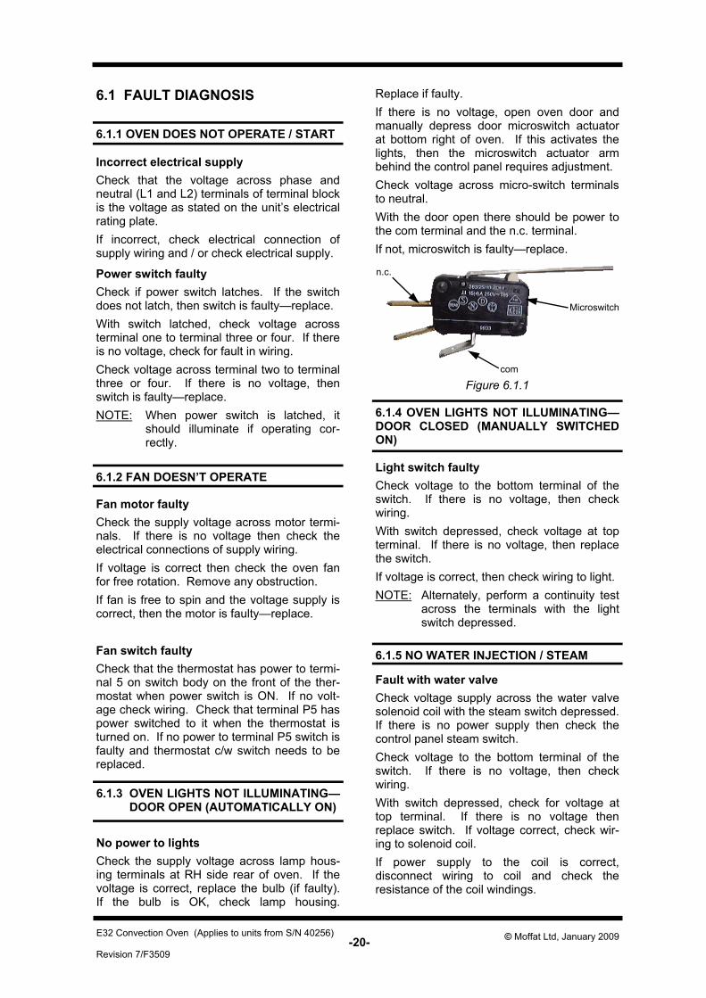
6.1.5 NO WATER INJECTION / STEAM Fault with water valve Check voltage supply across the water valve solenoid coil with the steam switch depressed. If there is no power supply then check the control panel steam switch. Check voltage to the bottom terminal of the switch. If there is no voltage, then check wiring. With switch depressed, check for voltage at top terminal. If there is no voltage then replace switch. If voltage correct, check wir-ing to solenoid coil. If power supply to the coil is correct, disconnect wiring to coil and check the resistance of the coil windings.
Microswitch
com
n.c.
Figure 6.1.1
Replace if faulty. If there is no voltage, open oven door and manually depress door microswitch actuator at bottom right of oven. If this activates the lights, then the microswitch actuator arm behind the control panel requires adjustment. Check voltage across micro-switch terminals to neutral. With the door open there should be power to the com terminal and the n.c. terminal. If not, microswitch is faulty—replace.
-21- Revision 7/F3509
© Moffat Ltd, January 2009 E32 Convection Oven (Applies to units from S/N 40256)
Correct coil resistance: 3650 ohms NOTE: If open circuit / high resistance, then the coil is faulty—replace. If coil resistance is correct, rewire and listen for an audible solenoid click when the steam switch is depressed. If solenoid can be heard functioning, and oven water nozzle is not blocked, then remove water solenoid and fittings and check for blockages.
6.1.6 CONTINUOUS WATER OUT OF OVEN WATER NOZZLE
Water solenoid electrical fault With control panel steam switch not depressed, check for power supply across solenoid coil. If there is power to the coil, then check wiring and steam switch (refer 6.1.5).
6.1.7 60 MINUTE TIMER NO TIME UP BUZZER
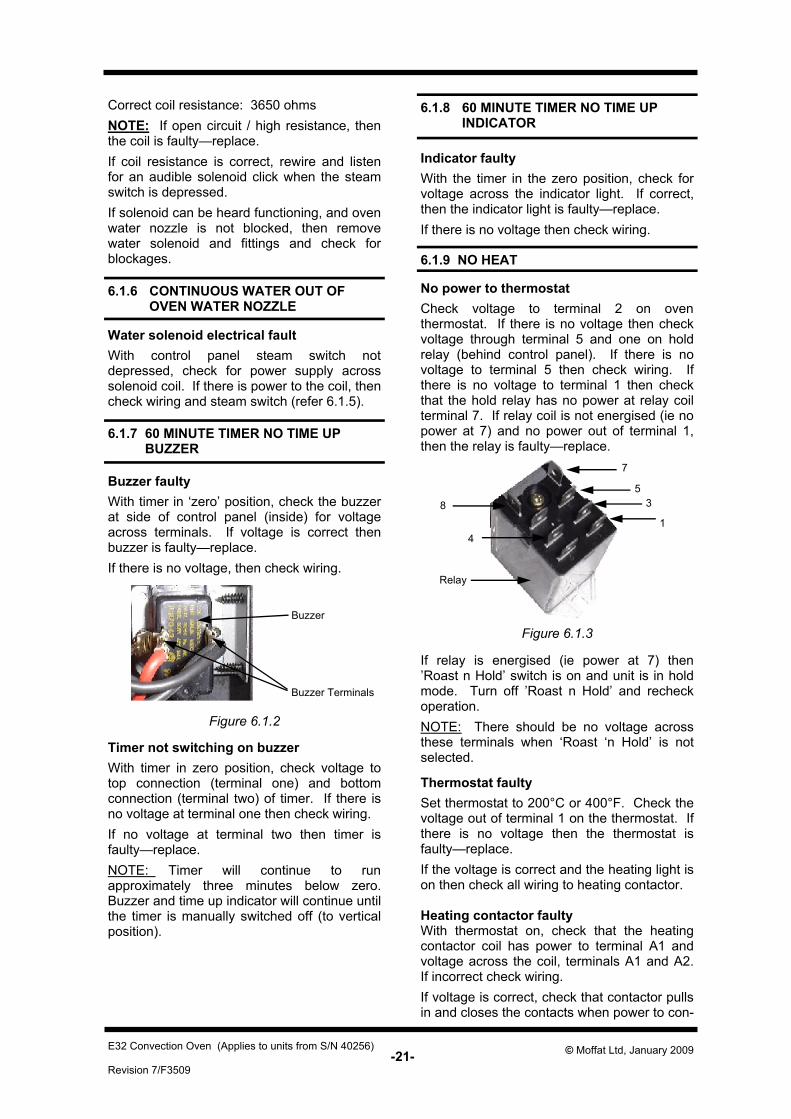
Buzzer faulty With timer in ‘zero’ position, check the buzzer at side of control panel (inside) for voltage across terminals. If voltage is correct then buzzer is faulty—replace. If there is no voltage, then check wiring.
Timer not switching on buzzer With timer in zero position, check voltage to top connection (terminal one) and bottom connection (terminal two) of timer. If there is no voltage at terminal one then check wiring. If no voltage at terminal two then timer is faulty—replace. NOTE: Timer will continue to run approximately three minutes below zero. Buzzer and time up indicator will continue until the timer is manually switched off (to vertical position).
6.1.9 NO HEAT
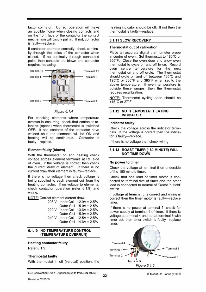
No power to thermostat Check voltage to terminal 2 on oven thermostat. If there is no voltage then check voltage through terminal 5 and one on hold relay (behind control panel). If there is no voltage to terminal 5 then check wiring. If there is no voltage to terminal 1 then check that the hold relay has no power at relay coil terminal 7. If relay coil is not energised (ie no power at 7) and no power out of terminal 1, then the relay is faulty—replace.
6.1.8 60 MINUTE TIMER NO TIME UP INDICATOR
Indicator faulty With the timer in the zero position, check for voltage across the indicator light. If correct, then the indicator light is faulty—replace. If there is no voltage then check wiring.
Thermostat faulty Set thermostat to 200°C or 400°F. Check the voltage out of terminal 1 on the thermostat. If there is no voltage then the thermostat is faulty—replace. If the voltage is correct and the heating light is on then check all wiring to heating contactor. Heating contactor faulty With thermostat on, check that the heating contactor coil has power to terminal A1 and voltage across the coil, terminals A1 and A2. If incorrect check wiring. If voltage is correct, check that contactor pulls in and closes the contacts when power to con-
Buzzer
Buzzer Terminals
Figure 6.1.2
If relay is energised (ie power at 7) then ’Roast n Hold’ switch is on and unit is in hold mode. Turn off ’Roast n Hold’ and recheck operation. NOTE: There should be no voltage across these terminals when ‘Roast ‘n Hold’ is not selected.
Figure 6.1.3
7
5 3
1 8
4
Relay
-22- Revision 7/F3509
© Moffat Ltd, January 2009 E32 Convection Oven (Applies to units from S/N 40256)
6.1.10 NO TEMPERATURE CONTROL (TEMPERATURE OVERRUN)
Heating contactor faulty Refer 6.1.9 Thermostat faulty With thermostat in off (vertical) position, the
6.1.11 SLOW RECOVERY Thermostat out of calibration Place an accurate digital thermometer probe in centre of oven. Set thermostat to 180°C or 355°F. Close the oven door and allow oven thermostat to cycle on and off twice. Record oven centre temperature for the next thermostat on and off cycle. The thermostat should cycle on and off between 165°C and 195°C or 330°F and 385°F when set to the above temperature. If oven temperature is outside these ranges, then the thermostat requires recalibration. NOTE: Thermostat cycling span should be ±15°C or 27°F
Indicator faulty Check the voltage across the indicator termi-nals. If the voltage is correct then the indica-tor is faulty—replace. If there is no voltage then check wiring.
6.1.12 NO THERMOSTAT HEATING INDICATOR
No power to timer Check the voltage at terminal 5 on underside of the 180 minute timer. Check that one lead of timer motor is con-nected to terminal five of timer and the other lead is connected to neutral of ‘Roast ’n Hold’ switch. If voltage at terminal 5 is correct and wiring is correct then the timer motor is faulty—replace timer. If there is no power at terminal 5, check for power supply at terminal 4 of timer. If there is voltage at terminal 4 and not at terminal 6 with timer set, then timer switch is faulty—replace timer.
6.1.13 ROAST TIMER (180 MINUTE) WILL NOT TIME DOWN
Figure 6.1.5
Terminal 4
Terminal 1
Terminal 2
Terminal 5 Terminal 3
Terminal 6
Terminal A1
Terminal 3
Terminal 2
Terminal A2
Terminal 1
Terminal 4
Figure 6.1.4
tactor coil is on. Correct operation will make an audible noise when closing contacts and on the front face of the contactor the contact mechanism will visibly pull in. If not, contactor is faulty—replace. If contactor operates correctly, check continu-ity through the poles of the contactor when closed. If no continuity through connected poles then contacts are blown and contactor requires replacing.
For checking elements where temperature overrun is occurring, check that contactor re-leases (opens) when thermostat is switched OFF. If not, contacts of the contactor have welded shut and elements will be ON and heating will be continuous. Contactor is faulty—replace. Element faulty (blown) With the thermostat on and heating check voltage across element terminals at RH side of oven. If the voltage is correct then check the current draw of element. If there is no current draw then element is faulty—replace. If there is no voltage then check voltage is being supplied to each element coil from the heating contactor. If no voltage to elements, check contactor operation (refer 6.1.9) and wiring. NOTE: Correct element current draw: 208 V : Inner Coil 12.9A ± 2.5% Outer Coil 15.0A ± 2.5% 220 V : Inner Coil 13.6A ± 2.5% Outer Coil 15.9A ± 2.5% 240 V : Inner Coil 12.5A ± 2.5% Outer Coil 14.6A ± 2.5%
heating indicator should be off. If not then the thermostat is faulty—replace.
-23- Revision 7/F3509
© Moffat Ltd, January 2009 E32 Convection Oven (Applies to units from S/N 40256)
‘Roast ‘n Hold’ switch faulty Check if the switch latches. If the switch does not latch then the switch is faulty—replace. With the switch latched, check voltage across terminal 1 to terminal 3 or 4. If there is no voltage then check for fault in wiring. Check voltage across terminal 2 to terminal 3 or 4. If there is no voltage then switch is faulty—replace. NOTE: When the switch is latched, it should illuminate if operating correctly.
If terminal 4 voltage is correct, check relay at the base of the control housing behind control panel is latched ON. If relay is ON then check wiring. If relay is not latched ON when ‘Roast ‘n Hold’ switch illuminated then check the voltage across terminals 7 and 8 of relay coil (fig 6.1.3). If the voltage is correct but the relay is in the off position then the relay is faulty—replace. If there is no voltage across 7 and 8 then check wiring.
Indicator faulty Check the voltage across the indicator termi-nals. If the voltage is correct then the indica-tor is faulty—replace. If there is no voltage then check wiring.
6.1.14 NO HOLD INDICATOR
Timer faulty NOTE: Timer in ‘HOLD’ position (vertical) and ‘Roast n Hold’ switch on (illuminated). Check the voltage at terminal three of timer, with timer in hold position. If the voltage is correct then check wiring. If there is no voltage then check voltage at terminal one of timer. If there is voltage at terminal one, but no voltage at terminal three with timer in hold position then timer switch is faulty—replace.
Hold thermostat faulty With the power switch on and illuminated, ‘Roast ‘n Hold’ switch on and illuminated, and the roast (180 minute) timer set to hold, check that the hold indicator is illuminated. With a cold oven (ie room temperature) check that the oven element is heating. Test the
6.1.15 HOLDING TEMPERATURE INCORRECT
voltage across the element terminals at the RH side of oven. If the voltage is correct then refer Fault: No heat (trouble shooting section). If there is no voltage at the element terminals, check the voltage at terminal 2 of the hold thermostat at RH side of control panel (fig 6.3.12). If there is no voltage then check wir-ing. If the voltage is correct, and the thermostat is adjusted above oven temperature, then check for output voltage at terminal 1 (bottom) of hold thermostat. If there is no voltage and the hold thermostat will not switch on then the thermostat is faulty—replace. If the voltage is correct but the element is not working then check wiring.
-24- Revision 7/F3509
© Moffat Ltd, January 2009 E32 Convection Oven (Applies to units from S/N 40256)
Figure 6.2.2
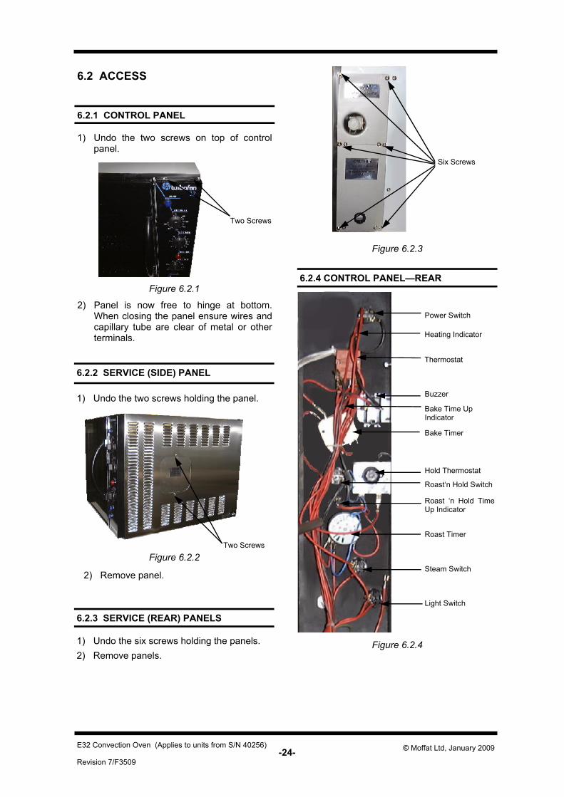
Buzzer
Power Switch
Heating Indicator
Thermostat
Bake Time Up Indicator
Roast‘n Hold Switch
Roast ‘n Hold Time Up Indicator
Roast Timer
Steam Switch
Light Switch
Hold Thermostat
Bake Timer
Two Screws
Two Screws
6.2 ACCESS
6.2.1 CONTROL PANEL
1) Undo the two screws on top of control panel.
1) Undo the two screws holding the panel.
6.2.2 SERVICE (SIDE) PANEL
1) Undo the six screws holding the panels. 2) Remove panels.
6.2.3 SERVICE (REAR) PANELS
2) Panel is now free to hinge at bottom. When closing the panel ensure wires and capillary tube are clear of metal or other terminals.
Figure 6.2.1
2) Remove panel.
Figure 6.2.3
6.2.4 CONTROL PANEL—REAR
Figure 6.2.4
Six Screws
-25- Revision 7/F3509
© Moffat Ltd, January 2009 E32 Convection Oven (Applies to units from S/N 40256)
Two Screws
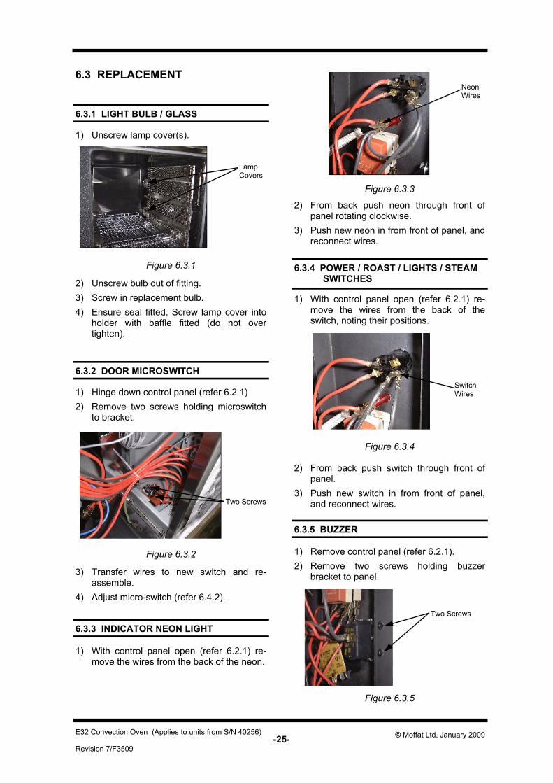
6.3 REPLACEMENT
6.3.1 LIGHT BULB / GLASS
6.3.2 DOOR MICROSWITCH
1) Unscrew lamp cover(s).
1) Hinge down control panel (refer 6.2.1) 2) Remove two screws holding microswitch
to bracket.
6.3.3 INDICATOR NEON LIGHT
1) With control panel open (refer 6.2.1) re-move the wires from the back of the neon.
6.3.4 POWER / ROAST / LIGHTS / STEAM SWITCHES
1) With control panel open (refer 6.2.1) re-move the wires from the back of the switch, noting their positions.
Two Screws
6.3.5 BUZZER
1) Remove control panel (refer 6.2.1). 2) Remove two screws holding buzzer
bracket to panel.
Figure 6.3.5
2) Unscrew bulb out of fitting. 3) Screw in replacement bulb. 4) Ensure seal fitted. Screw lamp cover into
holder with baffle fitted (do not over tighten).
Lamp Covers
Figure 6.3.1
3) Transfer wires to new switch and re-assemble.
4) Adjust micro-switch (refer 6.4.2).
Figure 6.3.2
2) From back push neon through front of panel rotating clockwise.
3) Push new neon in from front of panel, and reconnect wires.
2) From back push switch through front of panel.
3) Push new switch in from front of panel, and reconnect wires.
Neon Wires
Switch Wires
Figure 6.3.3
Figure 6.3.4
-26- Revision 7/F3509
© Moffat Ltd, January 2009 E32 Convection Oven (Applies to units from S/N 40256)
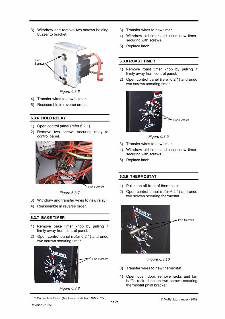
Two Screws
Two Screws
6.3.7 BAKE TIMER
1) Remove bake timer knob by pulling it firmly away from control panel.
2) Open control panel (refer 6.2.1) and undo two screws securing timer.
3) Withdraw and remove two screws holding buzzer to bracket.
4) Transfer wires to new buzzer. 5) Reassemble in reverse order.
Figure 6.3.6
6.3.8 ROAST TIMER
1) Remove roast timer knob by pulling it firmly away from control panel.
2) Open control panel (refer 6.2.1) and undo two screws securing timer.
6.3.9 THERMOSTAT
1) Pull knob off front of thermostat 2) Open control panel (refer 6.2.1) and undo
two screws securing thermostat.
3) Transfer wires to new timer. 4) Withdraw old timer and insert new timer,
securing with screws. 5) Replace knob.
3) Transfer wires to new timer. 4) Withdraw old timer and insert new timer,
securing with screws. 5) Replace knob.
Two Screws
Figure 6.3.7
Two Screws
Figure 6.3.8
4) Open oven door, remove racks and fan baffle rack. Loosen two screws securing thermostat phial bracket.
3) Transfer wires to new thermostat.
6.3.6 HOLD RELAY
1) Open control panel (refer 6.2.1). 2) Remove two screws securing relay to
control panel.
3) Withdraw and transfer wires to new relay. 4) Reassemble in reverse order.
Two Screws
Figure 6.3.9
Figure 6.3.10
-27- Revision 7/F3509
© Moffat Ltd, January 2009 E32 Convection Oven (Applies to units from S/N 40256)
6.3.10 HOLD THERMOSTAT
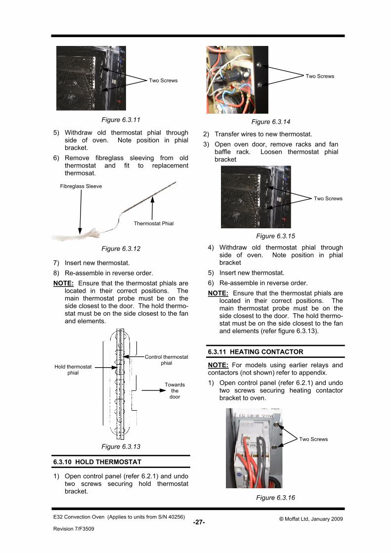
5) Withdraw old thermostat phial through side of oven. Note position in phial bracket.
6) Remove fibreglass sleeving from old thermostat and fit to replacement thermosat.
7) Insert new thermostat. 8) Re-assemble in reverse order. NOTE: Ensure that the thermostat phials are
located in their correct positions. The main thermostat probe must be on the side closest to the door. The hold thermo-stat must be on the side closest to the fan and elements.
Fibreglass Sleeve
Thermostat Phial
Figure 6.3.11
1) Open control panel (refer 6.2.1) and undo two screws securing hold thermostat bracket.
2) Transfer wires to new thermostat. 3) Open oven door, remove racks and fan
baffle rack. Loosen thermostat phial bracket
4) Withdraw old thermostat phial through side of oven. Note position in phial bracket
5) Insert new thermostat. 6) Re-assemble in reverse order. NOTE: Ensure that the thermostat phials are
located in their correct positions. The main thermostat probe must be on the side closest to the door. The hold thermo-stat must be on the side closest to the fan and elements (refer figure 6.3.13).
Figure 6.3.14
Figure 6.3.15
Figure 6.3.12
Two Screws Two Screws
Two Screws
6.3.11 HEATING CONTACTOR NOTE: For models using earlier relays and contactors (not shown) refer to appendix. 1) Open control panel (refer 6.2.1) and undo
two screws securing heating contactor bracket to oven.
Two Screws
Figure 6.3.16
Control thermostat phial
Hold thermostat phial
Towards the
door
Figure 6.3.13
-28- Revision 7/F3509
© Moffat Ltd, January 2009 E32 Convection Oven (Applies to units from S/N 40256)
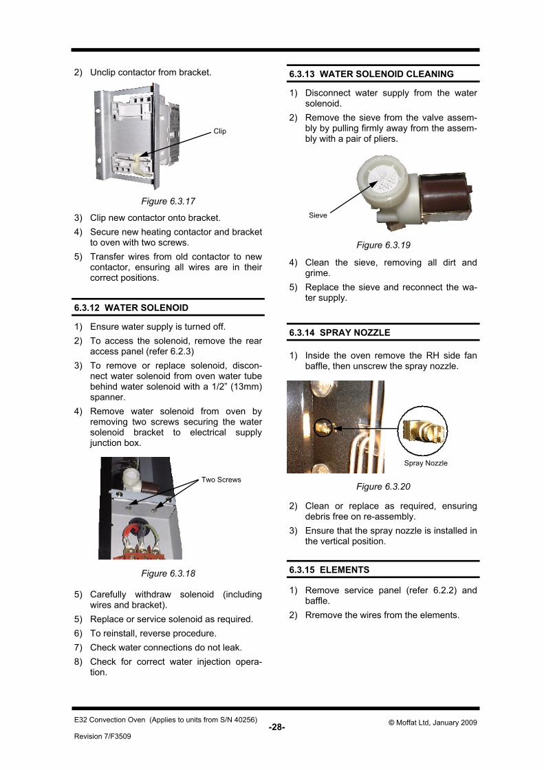
6.3.12 WATER SOLENOID
6.3.15 ELEMENTS
6.3.14 SPRAY NOZZLE 1) Ensure water supply is turned off. 2) To access the solenoid, remove the rear
access panel (refer 6.2.3) 3) To remove or replace solenoid, discon-
nect water solenoid from oven water tube behind water solenoid with a 1/2” (13mm) spanner.
4) Remove water solenoid from oven by removing two screws securing the water solenoid bracket to electrical supply junction box.
5) Carefully withdraw solenoid (including wires and bracket).
5) Replace or service solenoid as required. 6) To reinstall, reverse procedure. 7) Check water connections do not leak. 8) Check for correct water injection opera-
tion.
Figure 6.3.18
1) Inside the oven remove the RH side fan baffle, then unscrew the spray nozzle.
1) Remove service panel (refer 6.2.2) and baffle.
2) Rremove the wires from the elements.
Figure 6.3.19
Spray Nozzle
2) Clean or replace as required, ensuring debris free on re-assembly.
3) Ensure that the spray nozzle is installed in the vertical position.
6.3.13 WATER SOLENOID CLEANING 1) Disconnect water supply from the water
solenoid. 2) Remove the sieve from the valve assem-
bly by pulling firmly away from the assem-bly with a pair of pliers.
Sieve
4) Clean the sieve, removing all dirt and grime.
5) Replace the sieve and reconnect the wa-ter supply.
Figure 6.3.20 Two Screws
2) Unclip contactor from bracket.
Figure 6.3.17
Clip
3) Clip new contactor onto bracket. 4) Secure new heating contactor and bracket
to oven with two screws. 5) Transfer wires from old contactor to new
contactor, ensuring all wires are in their correct positions.
-29- Revision 7/F3509
© Moffat Ltd, January 2009 E32 Convection Oven (Applies to units from S/N 40256)
Two Screws
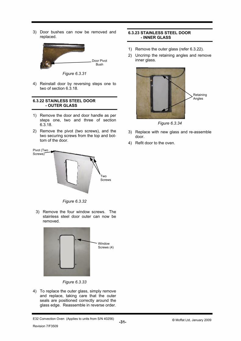
6.3.18 OUTER GLASS
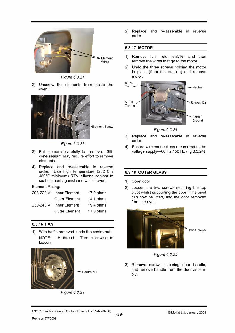
6.3.17 MOTOR
1) Remove fan (refer 6.3.16) and then remove the wires that go to the motor.
2) Undo the three screws holding the motor in place (from the outside) and remove motor.
1) Open door 2) Loosen the two screws securing the top
pivot whilst supporting the door. The pivot can now be lifted, and the door removed from the oven.
Figure 6.3.22
2) Unscrew the elements from inside the oven.
3) Pull elements carefully to remove. Sili-cone sealant may require effort to remove elements.
4) Replace and re-assemble in reverse order. Use high temperature (232°C / 450°F minimum) RTV silicone sealant to seal element against side wall of oven.
Element Rating: 208-220 V Inner Element 17.0 ohms Outer Element 14.1 ohms 230-240 V Inner Element 19.4 ohms Outer Element 17.0 ohms
3) Remove screws securing door handle, and remove handle from the door assem-bly.
Figure 6.3.21
Element Screw
Element Wires
6.3.16 FAN 1) With baffle removed undo the centre nut. NOTE: LH thread - Turn clockwise to
loosen.
Figure 6.3.25
Screws (3)
3) Replace and re-assemble in reverse order.
4) Ensure wire connections are correct to the voltage supply—60 Hz / 50 Hz (fig 6.3.24)
60 Hz Terminal
50 Hz Terminal
Earth / Ground
Neutral
2) Replace and re-assemble in reverse order.
Figure 6.3.24
Centre Nut
Figure 6.3.23

-30- Revision 7/F3509
© Moffat Ltd, January 2009 E32 Convection Oven (Applies to units from S/N 40256)
Door Seals Four Screws
Four Screws
6.3.19 INNER GLASS
1) Remove the outer glass (refer 6.3.18). Uncrimp the retaining lugs of the window spacer and remove the spacer and glass.
2) To replace, ensure the silicone rubber seal has not been displaced. Clean the glass and refit it. Place the window spacer in position and crimp the retaining lugs over to hold the glass in place. Refit outer glass as above.
Retaining Lugs
Figure 6.3.26
4) Remove four screws in top trim and four screws in bottom trim of door, and remove trim panels.
Figure 6.3.28
Figure 6.3.27
5) Lift outer glass away from door. 6) To replace, ensure that the two silicone
rubber seals are in place on the left hand and right hand side of the door frame. Clean the inside of the glass and refit it, ensuring that the silicone rubber seals cover the outer edges of the glass. Refit the trim panels.
Screws
Figure 6.3.29
Figure 6.3.30
6.3.20 DOOR SEALS
1) Open oven door. 2) To remove, hold at their centre point and
pull forward until they unclip
3) Refit new seals. Note: Fit top and bottom seals first, with
open side of seal facing down-wards. Fit side seals with open side facing outwards.
6.3.21 DOOR PIVOT BUSHES
1) Remove door as per steps one and two of section 6.3.18.
2) Remove the top and bottom pivot brackets (two screws).
Two Screws
-31- Revision 7/F3509
© Moffat Ltd, January 2009 E32 Convection Oven (Applies to units from S/N 40256)
Retaining Angles
Figure 6.3.31
Door Pivot Bush
3) Door bushes can now be removed and replaced.
4) Reinstall door by reversing steps one to two of section 6.3.18.
6.3.22 STAINLESS STEEL DOOR - OUTER GLASS
1) Remove the door and door handle as per steps one, two and three of section 6.3.18.
2) Remove the pivot (two screws), and the two securing screws from the top and bot-tom of the door.
3) Remove the four window screws. The stainless steel door outer can now be removed.
Figure 6.3.32
Pivot (Two Screws)
Two Screws
Figure 6.3.33
Window Screws (4)
4) To replace the outer glass, simply remove and replace, taking care that the outer seals are positioned correctly around the glass edge. Reassemble in reverse order.
1) Remove the outer glass (refer 6.3.22). 2) Uncrimp the retaining angles and remove
inner glass.
6.3.23 STAINLESS STEEL DOOR - INNER GLASS
Figure 6.3.34
3) Replace with new glass and re-assemble door.
4) Refit door to the oven.
-32- Revision 7/F3509
© Moffat Ltd, January 2009 E32 Convection Oven (Applies to units from S/N 40256)
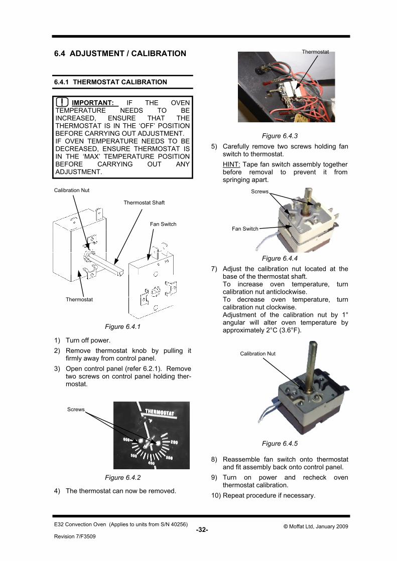
5) Carefully remove two screws holding fan switch to thermostat.
HINT: Tape fan switch assembly together before removal to prevent it from springing apart.
7) Adjust the calibration nut located at the base of the thermostat shaft.
To increase oven temperature, turn calibration nut anticlockwise.
To decrease oven temperature, turn calibration nut clockwise.
Adjustment of the calibration nut by 1° angular will alter oven temperature by approximately 2°C (3.6°F).
8) Reassemble fan switch onto thermostat and fit assembly back onto control panel.
9) Turn on power and recheck oven thermostat calibration.
10) Repeat procedure if necessary.
Screws
Fan Switch
Figure 6.4.4
Figure 6.4.5
Calibration Nut
Figure 6.4.3
Thermostat
Thermostat Shaft
Fan Switch
IMPORTANT: IF THE OVEN TEMPERATURE NEEDS TO BE INCREASED, ENSURE THAT THE THERMOSTAT IS IN THE ‘OFF’ POSITION BEFORE CARRYING OUT ADJUSTMENT. IF OVEN TEMPERATURE NEEDS TO BE DECREASED, ENSURE THERMOSTAT IS IN THE ‘MAX’ TEMPERATURE POSITION BEFORE CARRYING OUT ANY ADJUSTMENT.
1) Turn off power. 2) Remove thermostat knob by pulling it
firmly away from control panel. 3) Open control panel (refer 6.2.1). Remove
two screws on control panel holding ther-mostat.
4) The thermostat can now be removed.
Figure 6.4.2
Screws
Calibration Nut
Thermostat
Figure 6.4.1
6.4.1 THERMOSTAT CALIBRATION
6.4 ADJUSTMENT / CALIBRATION
-33- Revision 7/F3509
© Moffat Ltd, January 2009 E32 Convection Oven (Applies to units from S/N 40256)
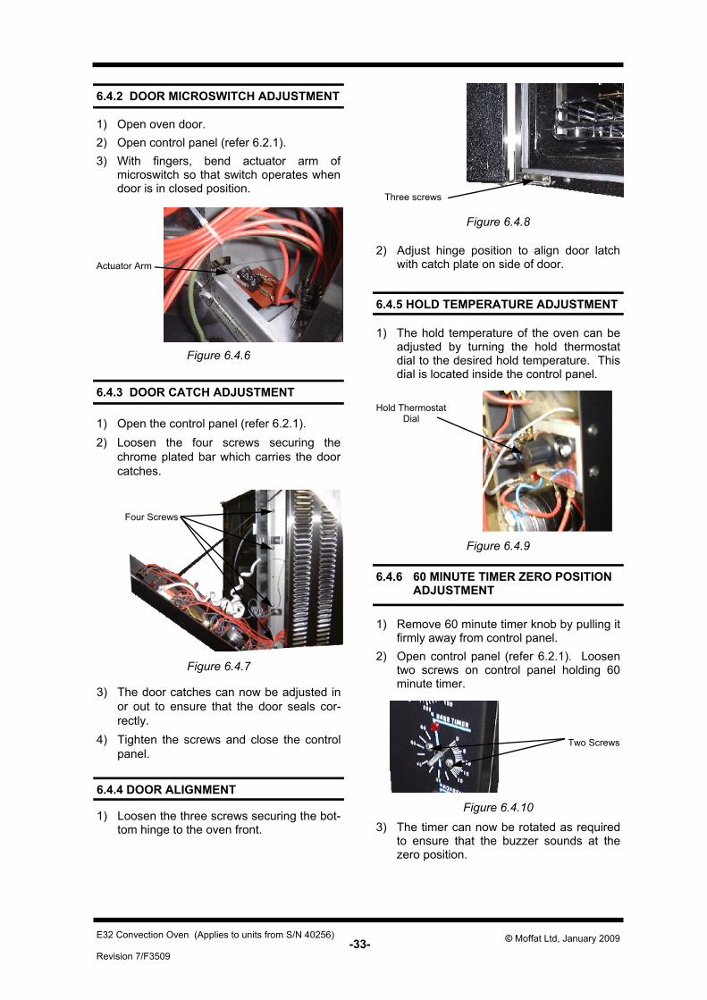
6.4.3 DOOR CATCH ADJUSTMENT
6.4.2 DOOR MICROSWITCH ADJUSTMENT
1) Open oven door. 2) Open control panel (refer 6.2.1). 3) With fingers, bend actuator arm of
microswitch so that switch operates when door is in closed position.
1) Open the control panel (refer 6.2.1). 2) Loosen the four screws securing the
chrome plated bar which carries the door catches.
3) The door catches can now be adjusted in or out to ensure that the door seals cor-rectly.
4) Tighten the screws and close the control panel.
Actuator Arm
Figure 6.4.6
Figure 6.4.9
Figure 6.4.7
6.4.5 HOLD TEMPERATURE ADJUSTMENT
1) The hold temperature of the oven can be adjusted by turning the hold thermostat dial to the desired hold temperature. This dial is located inside the control panel.
Hold Thermostat Dial
Figure 6.4.10
6.4.6 60 MINUTE TIMER ZERO POSITION ADJUSTMENT
1) Remove 60 minute timer knob by pulling it firmly away from control panel.
2) Open control panel (refer 6.2.1). Loosen two screws on control panel holding 60 minute timer.
Two Screws
3) The timer can now be rotated as required to ensure that the buzzer sounds at the zero position.
Four Screws
6.4.4 DOOR ALIGNMENT
1) Loosen the three screws securing the bot-tom hinge to the oven front.
Figure 6.4.8
2) Adjust hinge position to align door latch with catch plate on side of door.
Three screws
-34- Revision 7/F3509
© Moffat Ltd, January 2009 E32 Convection Oven (Applies to units from S/N 40256)
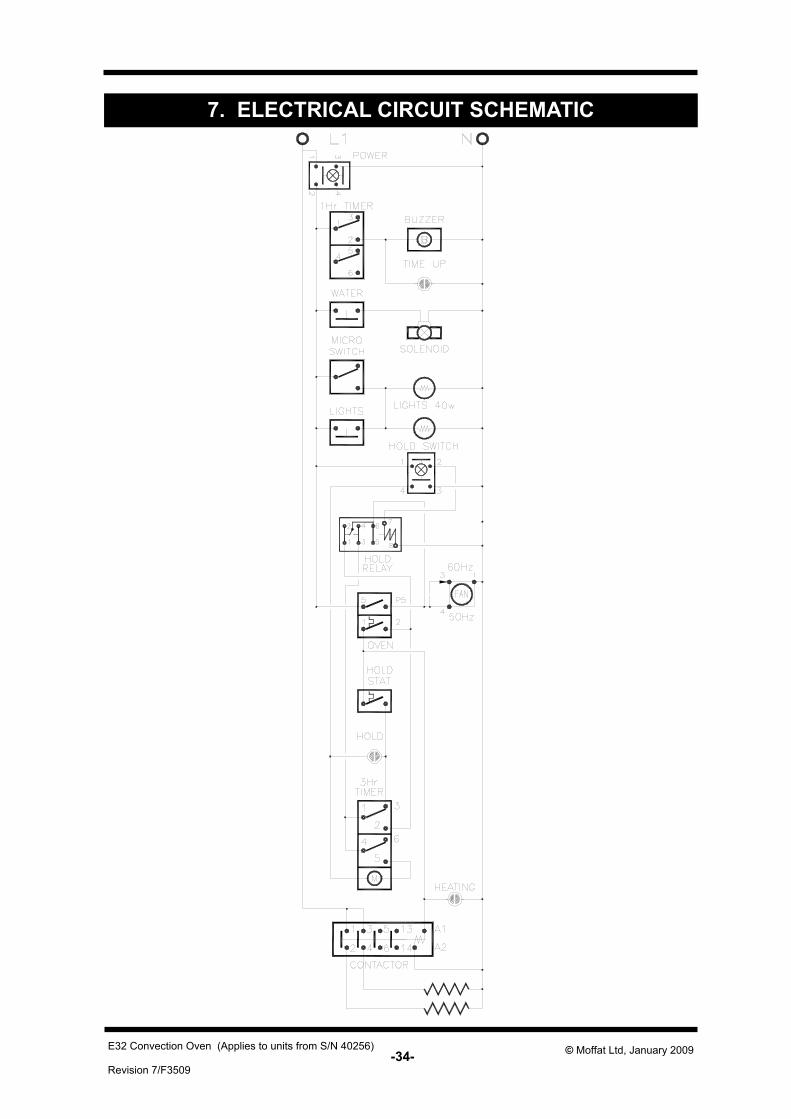
7. ELECTRICAL CIRCUIT SCHEMATIC
-35- Revision 7/F3509
© Moffat Ltd, January 2009 E32 Convection Oven (Applies to units from S/N 40256)
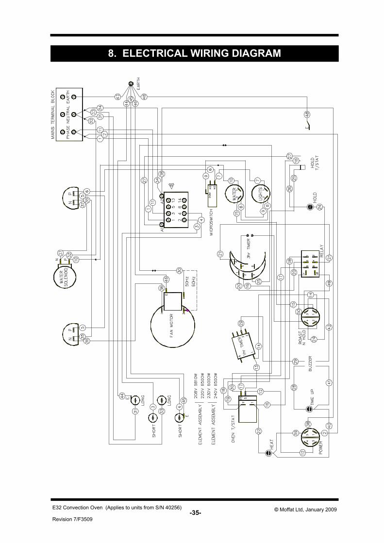
8. ELECTRICAL WIRING DIAGRAM
-36- Revision 7/F3509
© Moffat Ltd, January 2009 E32 Convection Oven (Applies to units from S/N 40256)
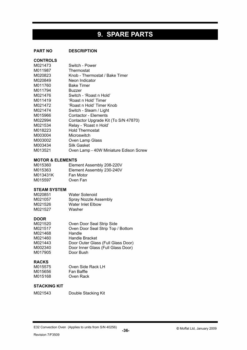
9. SPARE PARTS
PART NO DESCRIPTION
CONTROLS M021473 Switch - Power M011987 Thermostat M020823 Knob - Thermostat / Bake Timer M020849 Neon IndicatorM011760 Bake Timer M011794 Buzzer M021476 Switch - ‘Roast n Hold’ M011419 ‘Roast n Hold’ Timer M021472 ‘Roast n Hold’ Timer Knob M021474 Switch - Steam / Light M015966 Contactor - ElementsM022994 Contactor Upgrade Kit (To S/N 47870) M021534 Relay - ‘Roast n Hold’ M018223 Hold ThermostatM003004 MicroswitchM003002 Oven Lamp GlassM003434 Silk GasketM013521 Oven Lamp - 40W Miniature Edison Screw
MOTOR & ELEMENTS M015360 Element Assembly 208-220V M015363 Element Assembly 230-240V M013431K Fan Motor
Oven FanM015597
STEAM SYSTEM M020851 Water SolenoidM021057 Spray Nozzle Assembly M021526 Water Inlet Elbow M021527 Washer
DOOR M021520 Oven Door Seal Strip Side M021517 Oven Door Seal Strip Top / Bottom M021468 Handle M021460 Handle BracketM021443 Door Outer Glass (Full Glass Door) M002340 Door Inner Glass (Full Glass Door) M017905 Door Bush
RACKS M015575 Oven Side Rack LH M015656 Fan Baffle
Oven RackM015168
STACKING KIT M021543 Double Stacking Kit
-37- Revision 7/F3509
© Moffat Ltd, January 2009 E32 Convection Oven (Applies to units from S/N 40256)
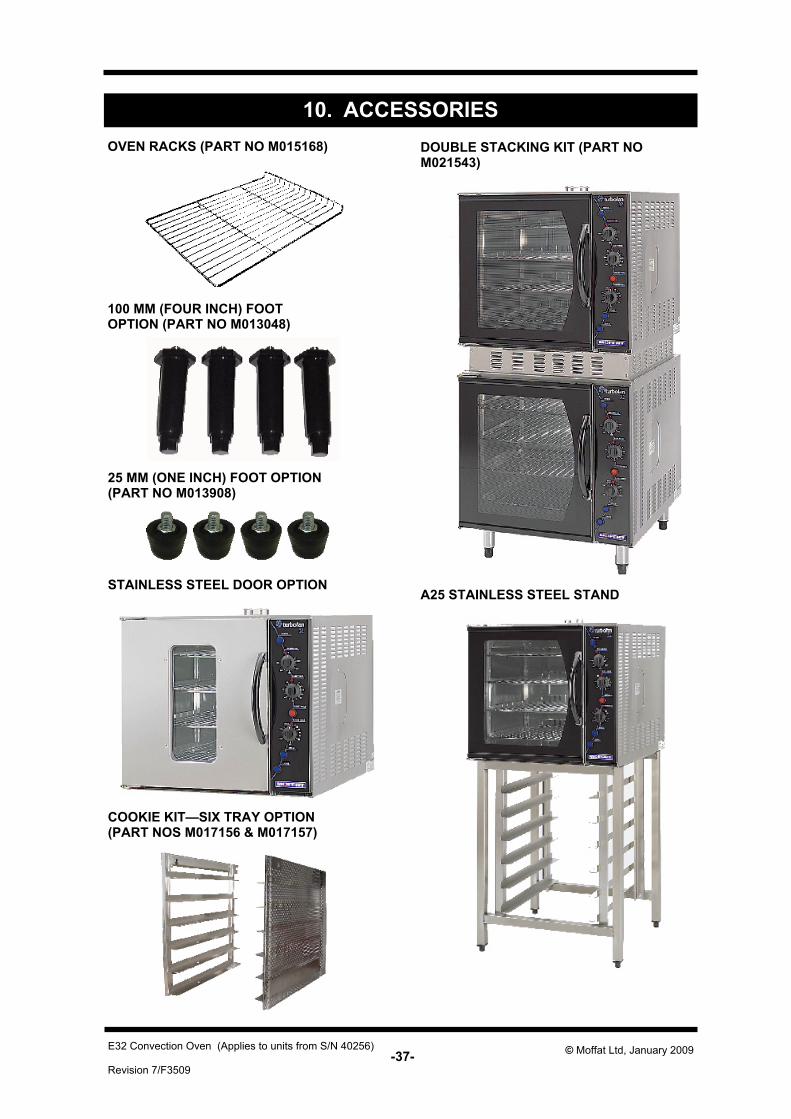
10. ACCESSORIESOVEN RACKS (PART NO M015168)
A25 STAINLESS STEEL STAND
DOUBLE STACKING KIT (PART NO M021543)
COOKIE KIT—SIX TRAY OPTION (PART NOS M017156 & M017157)
100 MM (FOUR INCH) FOOT OPTION (PART NO M013048)
25 MM (ONE INCH) FOOT OPTION (PART NO M013908)
STAINLESS STEEL DOOR OPTION
-38- Revision 7/F3509
© Moffat Ltd, January 2009 E32 Convection Oven (Applies to units from S/N 40256)
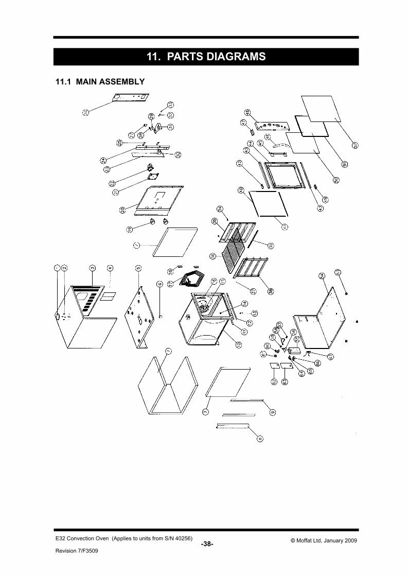
11. PARTS DIAGRAMS
11.1 MAIN ASSEMBLY
-39- Revision 7/F3509
© Moffat Ltd, January 2009 E32 Convection Oven (Applies to units from S/N 40256)
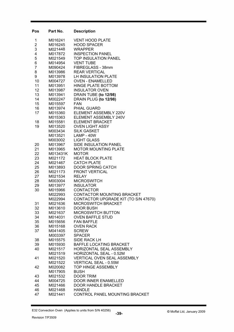
Pos Part No. Description
1 M016241 VENT HOOD PLATE 2 M016245 HOOD SPACER 3 M021448 WRAPPER 4 M017872 INSPECTION PANEL 5 M021549 TOP INSULATION PANEL 6 M014954 VENT TUBE 7 M090424 FIBREGLASS - 38mm 8 M013986 REAR VERTICAL 9 M013978 LH INSULATION PLATE 10 M004727 OVEN - ENAMELLED 11 M013951 HINGE PLATE BOTTOM 12 M013987 INSULATOR OVEN 13 M013941 DRAIN TUBE (to 12/98) 14 M002247 DRAIN PLUG (to 12/98) 15 M015597 FAN 16 M013974 PHIAL GUARD 17 M015360 ELEMENT ASSEMBLY 220V
M015363 ELEMENT ASSEMBLY 240V 18 M015581 ELEMENT BRACKET 19 M013520 OVEN LIGHT ASSY
M003434 SILK GASKET M013521 LAMP - 40W M003002 LIGHT GLASS
20 M013967 SIDE INSULATION PANEL 21 M013965 MOTOR MOUNTING PLATE 22 M013431K MOTOR 23 M021172 HEAT BLOCK PLATE 24 M021467 CATCH PLATE 25 M013893 DOOR SPRING CATCH 26 M021173 FRONT VERTICAL 27 M021534 RELAY 28 M003004 MICROSWITCH 29 M013977 INSULATOR 30 M015966 CONTACTOR
M022993 CONTACTOR MOUNTING BRACKET M022994 CONTACTOR UPGRADE KIT (TO S/N 47670)
31 M021636 MICROSWITCH BRACKET 32 M013610 DOOR BUSH 33 M021637 MICROSWITCH BUTTON 34 M014031 OVEN BAFFLE STUD 35 M015656 FAN BAFFLE 36 M015168 OVEN RACK 37 M041405 SCREW
M003397 SPACER 38 M015575 SIDE RACK LH 39 M015930 BAFFLE LOCATING BRACKET 40 M021517 HORIZONTAL SEAL ASSEMBLY M021519 HORIZONTAL SEAL - 0.52M 41 M021520 VERTICAL OVEN SEAL ASSEMBLY
M021522 VERTICAL SEAL - 0.55M 42 M020082 TOP HINGE ASSEMBLY M017905 BUSH 43 M021532 DOOR TRIM 44 M004725 DOOR INNER ENAMELLED 45 M021466 DOOR HANDLE BRACKET 46 M021468 HANDLE 47 M021441 CONTROL PANEL MOUNTING BRACKET
-40- Revision 7/F3509
© Moffat Ltd, January 2009 E32 Convection Oven (Applies to units from S/N 40256)
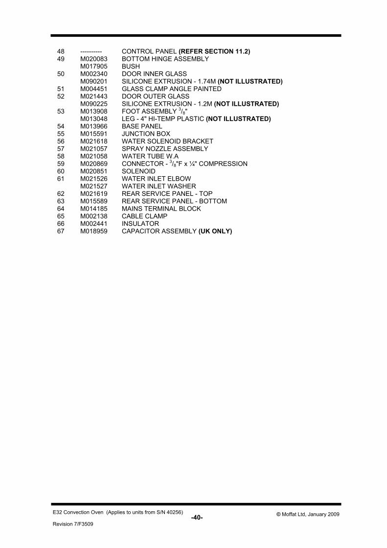
48 ---------- CONTROL PANEL (REFER SECTION 11.2) 49 M020083 BOTTOM HINGE ASSEMBLY M017905 BUSH 50 M002340 DOOR INNER GLASS
M090201 SILICONE EXTRUSION - 1.74M (NOT ILLUSTRATED) 51 M004451 GLASS CLAMP ANGLE PAINTED 52 M021443 DOOR OUTER GLASS
M090225 SILICONE EXTRUSION - 1.2M (NOT ILLUSTRATED) 53 M013908 FOOT ASSEMBLY 3/8"
M013048 LEG - 4" HI-TEMP PLASTIC (NOT ILLUSTRATED) 54 M013966 BASE PANEL 55 M015591 JUNCTION BOX 56 M021618 WATER SOLENOID BRACKET 57 M021057 SPRAY NOZZLE ASSEMBLY 58 M021058 WATER TUBE W.A 59 M020869 CONNECTOR - 3/8"F x ¼" COMPRESSION 60 M020851 SOLENOID 61 M021526 WATER INLET ELBOW
M021527 WATER INLET WASHER 62 M021619 REAR SERVICE PANEL - TOP 63 M015589 REAR SERVICE PANEL - BOTTOM 64 M014185 MAINS TERMINAL BLOCK 65 M002138 CABLE CLAMP 66 M002441 INSULATOR 67 M018959 CAPACITOR ASSEMBLY (UK ONLY)
-41- Revision 7/F3509
© Moffat Ltd, January 2009 E32 Convection Oven (Applies to units from S/N 40256)
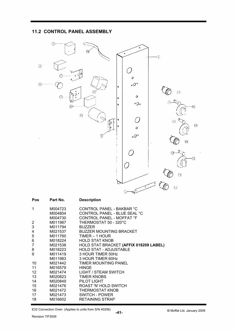
11.2 CONTROL PANEL ASSEMBLY
Pos Part No. Description
1 M004723 CONTROL PANEL - BAKBAR °C M004804 CONTROL PANEL - BLUE SEAL °C M004730 CONTROL PANEL - MOFFAT °F
2 M011987 THERMOSTAT 50 - 320°C 3 M011794 BUZZER 4 M021537 BUZZER MOUNTING BRACKET 5 M011760 TIMER – 1 HOUR 6 M018224 HOLD STAT KNOB 7 M021538 HOLD STAT BRACKET (AFFIX 018209 LABEL) 8 M018223 HOLD STAT - ADJUSTABLE 9 M011419 3 HOUR TIMER 50Hz
M011983 3 HOUR TIMER 60Hz 10 M021442 TIMER MOUNTING PANEL 11 M016579 HINGE 12 M021474 LIGHT / STEAM SWITCH 13 M020823 TIMER KNOBS 14 M020849 PILOT LIGHT 15 M021476 ROAST 'N' HOLD SWITCH 16 M021472 THERMOSTAT KNOB 17 M021473 SWITCH - POWER 18 M016602 RETAINING STRAP
-42- Revision 7/F3509
© Moffat Ltd, January 2009 E32 Convection Oven (Applies to units from S/N 40256)
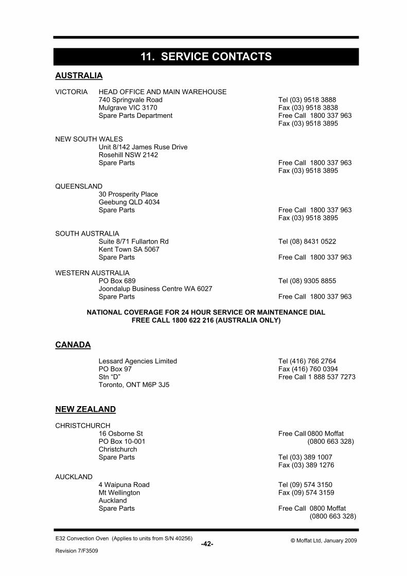
11. SERVICE CONTACTSAUSTRALIA
VICTORIA HEAD OFFICE AND MAIN WAREHOUSE 740 Springvale Road Tel (03) 9518 3888 Mulgrave VIC 3170 Fax (03) 9518 3838 Spare Parts Department Free Call 1800 337 963
Fax (03) 9518 3895
NEW SOUTH WALES Unit 8/142 James Ruse Drive Rosehill NSW 2142Spare Parts Free Call 1800 337 963
Fax (03) 9518 3895
QUEENSLAND 30 Prosperity Place Geebung QLD 4034 Spare Parts Free Call 1800 337 963
Fax (03) 9518 3895
SOUTH AUSTRALIA Suite 8/71 Fullarton Rd Tel (08) 8431 0522 Kent Town SA 5067 Spare Parts Free Call 1800 337 963
WESTERN AUSTRALIA PO Box 689 Tel (08) 9305 8855 Joondalup Business Centre WA 6027 Spare Parts Free Call 1800 337 963
NATIONAL COVERAGE FOR 24 HOUR SERVICE OR MAINTENANCE DIAL FREE CALL 1800 622 216 (AUSTRALIA ONLY)
CANADA
Lessard Agencies Limited Tel (416) 766 2764 PO Box 97 Fax (416) 760 0394 Stn “D” Free Call 1 888 537 7273 Toronto, ONT M6P 3J5
NEW ZEALAND
CHRISTCHURCH 16 Osborne St Free Call 0800 Moffat PO Box 10-001 (0800 663 328) ChristchurchSpare Parts Tel (03) 389 1007
Fax (03) 389 1276
AUCKLAND 4 Waipuna Road Tel (09) 574 3150 Mt Wellington Fax (09) 574 3159 AucklandSpare Parts Free Call 0800 Moffat
(0800 663 328)
-43- Revision 7/F3509
© Moffat Ltd, January 2009 E32 Convection Oven (Applies to units from S/N 40256)
UNITED KINGDOM
BLUESEAL LTDUnits 6-7 Mount St Tel 0121-327 5575 Business Park Fax 0121-327 9711 Birmingham B7 5QUEngland
UNITED STATES OF AMERICA
MOFFAT INC.3765 Champion BlvdWinston-Salem Tel 1-800-551 8795 NC27115 Fax 336 661 9546
NATIONAL COVERAGE FOR SERVICE OR MAINTENANCE DIAL FREE CALL 1800 551 8795 (USA ONLY)