Embed Size (px)
Citation preview

TAC PACK TCU PROGRAMMING REFERENCE


TAC PACK TCU PROGRAMMING REFERENCE
© Data Flow Systems, Inc . 605 N. John Rodes Blvd. , Melbourne , FL 32934
Phone 321-259-5009 • Fax 321-259-4006

NOTICE
Data Flow Systems, Inc. assumes no responsibility for any errors that may appear in this document, nor does it make any commitment to update the information contained herein. However, questions regarding the information contained in this document are welcomed.
Data Flow Systems also reserves the right to make changes to the specifications of TAC Pack TCU and to the information contained in this document at any time without notice.
This document contains information related to special features and functions that are only available when the TAC Pack TCU is utilized in a DFS TAC II SCADA System. These special features and functions may not be available when the TCU001 is utilized in a 3rd party SCADA System. If you are unsure about the availability of a feature or function, please contact DFS for clarification.
DFS-00367-011-03
This document las t rev ised : Apr i l 21 , 2018

i
TABLE OF CONTENTS
PREFACE .................................................................................................................................. 1 Purpose of this Manual ..................................................................................................................... 1 Downward Compatibility Issues ....................................................................................................... 1
PCU and PCU TAC Pack ............................................................................................................ 1 SCU and SCU TAC Pack ............................................................................................................ 2
Document Conventions..................................................................................................................... 2 Abbreviations Used in this Manual................................................................................................... 2
CHAPTER 1: DEFINITION OF TERMS ........................................................................................ 3 Abbreviations .................................................................................................................................... 3 Argument Stack................................................................................................................................. 3 Carriage Return (CR) ........................................................................................................................ 3 Control Stack .................................................................................................................................... 3 DFS Special (Telemetry) .................................................................................................................. 4 Expression......................................................................................................................................... 4
PI.................................................................................................................................................. 4 Logical Expression ...................................................................................................................... 4 Relational Expression .................................................................................................................. 5
Run Trap Mode ................................................................................................................................. 5 System Control Values...................................................................................................................... 5 Variables ........................................................................................................................................... 6
CHAPTER 2: COMMANDS AND STATEMENTS............................................................................ 9 EPROM Commands.......................................................................................................................... 9
EPROG Command....................................................................................................................... 9 ERASE Command ....................................................................................................................... 9 RAM Command......................................................................................................................... 10 ROM Command......................................................................................................................... 10 XFER Command ....................................................................................................................... 10
BASIC Commands.......................................................................................................................... 11 (Ctrl) C Command ..................................................................................................................... 11 CONT Command....................................................................................................................... 11 LIST Command ......................................................................................................................... 12 NEW Command......................................................................................................................... 12 NULL Command ....................................................................................................................... 13 RUN Command ......................................................................................................................... 13
BASIC Statements .......................................................................................................................... 14 CALL Statement ........................................................................................................................ 14 CHKTIMER Statement.............................................................................................................. 15 CLEAR Statement ..................................................................................................................... 15 CLEARS Statement ................................................................................................................... 15 DATA, READ, RESTORE Statements ..................................................................................... 17 DIM Statement........................................................................................................................... 18 DO, UNTIL Statements ............................................................................................................. 19 DO, WHILE Statements ............................................................................................................ 20 END Statement .......................................................................................................................... 21

ii
FOR, TO, NEXT Statements ......................................................................................................22 GOSUB, RETURN Statements ..................................................................................................23 GOTO Statement ........................................................................................................................25 IF, THEN, ELSE STATEMENTS..............................................................................................26 INPUT Statement........................................................................................................................27 LD@ Statement ..........................................................................................................................28
Memory Image Updating via PLC Editor .............................................................................29 Floating Point Format............................................................................................................29
LET Statement ............................................................................................................................30 MENU Statement........................................................................................................................31
MENU ...................................................................................................................................31 MENU ON.............................................................................................................................32 MENU OFF...........................................................................................................................32 MENU CLR...........................................................................................................................33 MENU (define menu pages)..................................................................................................33 MENU INPUT.......................................................................................................................34 MENU PLOT ........................................................................................................................35
ON Statement..............................................................................................................................36 ONERR Statement......................................................................................................................38 PH0., PH1., PH0.#, PH1.# Statements .......................................................................................38 POP Statement ............................................................................................................................39 PRINT or P. or ? Statement ........................................................................................................41
Special Print Formatting Statements .....................................................................................42 PRINT@ or P.@ or ?@ Statement .............................................................................................45 PRINT# or P.# or ?# Statement ..................................................................................................45 PUSH Statement .........................................................................................................................45 REM Statement...........................................................................................................................47 RROM Statement........................................................................................................................48 SETIMER Statement ..................................................................................................................48 ST@ Statement ...........................................................................................................................49 STOP Statement..........................................................................................................................50 STRING Statement .....................................................................................................................50
String Expression Calculation ...............................................................................................51 TAC II Interface Statements ............................................................................................................52
ANIN Statement .........................................................................................................................52 ANOUNT Statement ..................................................................................................................53 DEFMOD Statement ..................................................................................................................55 DGIN Statement .........................................................................................................................57
Positive Edge Trigger Option (,^) .........................................................................................59 DGOUT Statement .....................................................................................................................60
Using DGOUT to Control LEDs ...........................................................................................60 Using DGOUT to Manipulate Qualifier Point Status............................................................61
POLLOFF Statement ..................................................................................................................62 POLLON Statement....................................................................................................................63 SYSCHECK Statement ..............................................................................................................64
SYSCHECK on Remote Modules.........................................................................................65 SYSTIME Statement ..................................................................................................................65
Setting the System Time........................................................................................................67

iii
CHAPTER 3: OPERATORS AND EXPRESSIONS......................................................................... 69 Dual Operand Operators ................................................................................................................. 69
Arithmetic Operators ................................................................................................................. 69 Exponentiation Operator....................................................................................................... 69 Multiplication Operator ........................................................................................................ 69 Division Operator ................................................................................................................. 69 Addition Operator................................................................................................................. 69 Subtraction Operator............................................................................................................. 70
Logical Operators ...................................................................................................................... 70 AND Operator ...................................................................................................................... 70 OR Operator ......................................................................................................................... 70 Exclusive OR Operator......................................................................................................... 70
Unary Operators.............................................................................................................................. 71 General Purpose Operators ........................................................................................................ 71
Absolute Value Operator ...................................................................................................... 71 E - Exponent Operator .......................................................................................................... 71 Integer Operator.................................................................................................................... 71 Logarithmic Operator ........................................................................................................... 71 Not Operator ......................................................................................................................... 72 Random Number Operator ................................................................................................... 72 Sign Operator........................................................................................................................ 72 Square Root Operator ........................................................................................................... 73
Trigonometric Operators............................................................................................................ 73 Arctangent Operator ............................................................................................................. 73 Cosine Operator.................................................................................................................... 74 Sine Operator........................................................................................................................ 74 Tangent Operator.................................................................................................................. 74
Understanding Precedence Of Operators ........................................................................................ 75 How Relational Expressions Work ................................................................................................. 75 Strings and String Operators ........................................................................................................... 76
String Operators......................................................................................................................... 77 ASCII Operator..................................................................................................................... 77 Character Operator ............................................................................................................... 79 Clear Screen & Cursor “Home” Print Statements ................................................................ 79
Special Function Operators ............................................................................................................. 80 DBY ([expr]) ............................................................................................................................. 80 GET............................................................................................................................................ 80 XBY........................................................................................................................................... 81 System Control Values .............................................................................................................. 81
FREE .................................................................................................................................... 81 LEN ...................................................................................................................................... 81 MTOP ................................................................................................................................... 82
CHAPTER 4: ERROR MESSAGES AND ANOMALIES ................................................................. 83 Error Messages................................................................................................................................ 83
A-Stack ...................................................................................................................................... 83 Array Size .................................................................................................................................. 83 Arith. Overflow.......................................................................................................................... 83 Arith. Underflow....................................................................................................................... 84

iv
Bad Argument.............................................................................................................................84 Bad Syntax..................................................................................................................................84 C-Stack .......................................................................................................................................84 Can't Continue ............................................................................................................................85 Divide By Zero ...........................................................................................................................85 Extra Ignored ..............................................................................................................................85 I-Stack.........................................................................................................................................85 Illegal Direct ...............................................................................................................................85 Invalid Menu Option...................................................................................................................85 Line Too Long ............................................................................................................................85 Memory Allocation.....................................................................................................................86 No Data.......................................................................................................................................86 Programming ..............................................................................................................................86
Anomalies ........................................................................................................................................86 APPENDIX A: RESERVED KEYWORDS .................................................................................... 89 APPENDIX B: FREE EXTERNAL MEMORY STORAGE MAP ..................................................... 91

1
PREFACE
PURPOSE OF THIS MANUAL
This manual covers the DFS BASIC-52 commands and syntax that can be used when programming the TCU. If the TCU is being used in a non-pump control application or in an application that requires control processes beyond those provided in the TCU’s built-in pump control process, a customized program can be developed. Using DFS BASIC-52, the TCU can be programmed to perform a variety of automated tasks when interfaced with other DFS or Modbus-compatible telemetry equipment and field instrumentation.
It should be noted, however, that this manual does not include instructions on how to write BASIC programs. Books on programming in BASIC and QBasic can be found in local and Internet-based bookstores. There are also Web sites that provide information, including instruction and tutorials, on BASIC and QBasic. (QBasic is a version of BASIC that is similar enough to the original to be useful when learning to program the TCU.)
Note that this manual only provides information on programming the TCU. Instructions and diagrams for power, 3-phase monitor circuitry, individual I/O point, and telemetry wiring can be found in the TCU Installation and Operation Manual (part number DFS-00367-011-02).
DOWNWARD COMPATIBILITY ISSUES
When developing the TAC Pack TCU, DFS made every effort to make the TCU downward compatible with the Pump Control Unit (PCU), PCU TAC Pack, Supervisory & Control Unit (SCU), and SCU TAC Pack. There are a few important differences, however, that must be addressed when replacing one unit type with another.
Please note that the PCU, PCU TAC Pack, SCU, and SCU TAC Pack are not "upward" compatible with the TCU. DFS' Sales Department can provide assistance with ensuring that your system has appropriate replacement units on hand. Contact DFS' Sales Department (321-259-5009; [email protected]) for more information.
PCU and PCU TAC Pack
When using a TCU to replace a PCU that was providing power to an analog level transducer, transducer power must be acquired from pin P2-16 of the TCU. In a PCU installation, power could be acquired from pins P2-21 or P2-16. When upgrading to a TCU, the wire from P2-21 (PCU) must be moved to P2-16 (TCU). More information on wiring an analog level transducer can be found in the TCU Installation and Operation Manual.

Preface
TCU Programming Reference 2
SCU and SCU TAC Pack
In order for an existing SCU program to run interchangeably on both an SCU and a TCU, at least four modifications must be made to the program:
• Add code that determines if the program is running on a TCU or an SCU • Change how the program reads the phase monitor. The TCU's C3 and C4 points (Phase AB Voltage
and Phase AC Voltage, respectively) have greater ranges for the engineering and raw units values than those for the SCU. The ranges for an SCU are 151-300 VAC over a 0-255 raw units span. The ranges for a TCU are 0-350 VAC over a 0-3888 raw units span.
• Remap two I/O points wired to connector P2. In the SCU, pin P2-12 is mapped to HyperTAC II address point A11; pin P2-13 is mapped to point A12. In order for the TCU to be downwardly compatible with the Legacy PCU, and have the ability to transmit pulse input data to HyperTAC II, the TCU doesn’t map these two inputs the same as the SCU. In the TCU, pin P2-12 (Legacy PCU auxiliary digital monitor input, now available for use as a digital pulse input) is mapped to HyperTAC II address point A12; pin P2-13 (Legacy PCU alarm silence switch digital monitor input) is mapped to HyperTAC II address point B7.
• Change how the menus are displayed and how keypad entries are made. • Add a loop timer (optional) to compensate for the TCU’s quicker loop time.
These differences need to be addressed in the configuration and programming of any SCU being replaced by a TCU. An Engineering Information Bulletin (EIB) with detailed information on the SCU/TCU process conversion has been released. Contact DFS' Service Department for assistance with making the required modifications.
DOCUMENT CONVENTIONS
The following conventions are used throughout this manual:
• Bulleted lists provide information, not procedural steps. • Numbered lists provide sequential steps or hierarchal information. • Bold italic type is used for emphasis • Italic type is used to indicate text displayed on the LCD screen. • ALL CAPITALIZED ITALIC type is used for terminal names.
ABBREVIATIONS USED IN THIS MANUAL
H-O-A – Hand-Off-Auto I/O – Input/Output PCU – Pump Control Unit PLC – Programmable Logic Controller RTU – Remote Terminal Unit SCU – Supervisory & Control Unit TCU – TAC Pack Telemetry Control Unit

3
Chapter 1: DEFINITION OF TERMS
ABBREVIATIONS
[ ] indicates required parameter { } indicates optional parameter const constant cr carriage return expr expression ln num line number rel expr relational expression var variable
ARGUMENT STACK
The argument stack is memory reserved for transferring data values from one area of the TCU to another. When working with the argument stack, it is important to note that a value placed on the argument stack by one command, must be removed with another command.
An error occurs when accessing the argument stack in the following circumstances:
• Too many items are placed on the argument stack. • An attempt is made to remove a value from the argument stack when there is no value present
(except for the Menu Statement). Some commands that utilize the argument stack are MENU, SYSTIME, SYSCHECK, and telemetry function commands such as DGIN and DGOUT.
CARRIAGE RETURN (CR)
The carriage return represents the action of pressing the Enter or Return key on the console device or keyboard. All commands, when typed in at the command prompt (>), require a carriage return in order for the command to be executed. Throughout this manual, the carriage return is indicated by (cr).
CONTROL STACK
The control stack is external memory reserved for monitoring the foreground program operations. There are 158 bytes of external memory allocated to the control stack. This allows commands such as FOR---NEXT and GOSUB---RETURN to be executed.
• The FOR---NEXT (loop) statement requires 17 bytes of control stack memory. • The DO---UNTIL, DO---WHILE, and GOSUB---RETURN statements each require three bytes of
CONTROL STACK memory.
As a result, the maximum that DFS BASIC-52 can handle is nine nested FOR---NEXT loops (9 x 17 = 153).
A C-STACK error occurs if:
• A program attempts to use more control stack memory than is available in DFS BASIC-52. • A RETURN is executed before a GOSUB

Chapter 1: Definition of Terms
TCU Programming Reference 4
• A WHILE or UNTIL is executed before a DO • A NEXT is executed before a FOR.
DFS SPECIAL (TELEMETRY)
In the DFS BASIC-52 command set, there are special function commands that most likely will not appear in other versions of Industrial BASIC. These statements, explained in detail in Chapter 2: Commands and Statements, are designated with Type: DFS Special. Some of the DFS Special commands are used solely for the telemetry interface and are designated Type: Telemetry.
EXPRESSION
An expression is a logical or mathematical formula that involves operators, constants, and variables. Expressions can be simple or quite complex. A "stand alone" variable [var] or constant [const] is also considered an expression. This document will refer to expressions with the following indicator:
[expr]
In the example below, the letter A is a variable, the 3 and 15 are constants, and the + and > signs are operators. See Chapter 3: Operators and Expressions for details on operators.
A+3>15
PI
PI is a stored constant in DFS BASICS-52. This constant is stored as 3.1415926, instead of the more common 3.1415927, to reconcile errors found in the SIN, COS, and TAN operators. The number PI/2 is needed to calculate these operators and it is desirable, for the sake of accuracy, to have the equation PI/2 + PI/2 = PI hold true. This cannot be done if the last digit is an odd number, so the last digit of PI was rounded to 6 to make these calculations more accurate.
Logical Expression
Logical expressions are expressions that involve true/false decisions (see example below). Logical expressions can be assigned to a variable just like numeric expressions and can be used to derive intermediate logical variables used in decision-making. To do this, DFS BASIC-52 assigns the following values:
• A true value is equal to 65535.
• A false value is equal to 0 (zero).
Note: When the TCU is first turned on, all variables are equal to 0 (zero).
TR=NOT(FA)
In the example above, TR and FA are variables. By using the unary operator NOT, the value of TR is now 65535 while the value of FA is still 0 (zero). This is useful when variables in a program need to be assigned to an on state (TR) or off state (FA).

Chapter 1: Definition of Terms
TCU Programming Reference 5
Relational Expression
Relational expressions involve the following operators:
• = (equal)
• <> (not equal)
• > (greater than)
• < (less than)
• >= (greater than or equal to)
• <= (less than or equal to)
Relational expressions are used in control statements to "test" a condition (e.g., IF A<100 THEN...). Relational expressions always require two operands. In this document, relational expressions are indicated as follows:
[rel expr].
Programmer's Note: When using these variables in an IF statement, always place parenthesis around them to distinguish the variable from the rest of the statement. For example: IF (A=10); IF (B>=30)
The example below will display "Start OK" and cause the cursor to stop where it finishes printing whenever CALED and RAN are true, or when TIME is greater than 200. When CALED or RAN is false and TIME is less than 200, “Not started” will be displayed and the cursor will return to the beginning of the line on which it just wrote. See Chapter 3: Operators and Expressions for more details on relational expressions.
>LIST
10 START=(CALED).AND.(RAN).OR.(TIME>200)
20 IF (START) THEN PRINT "START OK" ELSE PRINT "NOT STARTED", CR ,
READY
>
RUN TRAP MODE
DFS BASIC-52 permits the user to “trap” the interpreter in Run mode. The TCU automatically enters Run mode on power up unless the 1 (one) key is held down while powering up the unit. When the 1 (one) key is held down during power up, the TCU switches into Debug mode.
SYSTEM CONTROL VALUES
The system control values include the following:
• LEN – returns the length of the program. • FREE – returns the number of bytes of free RAM. • MTOP – returns the last memory location assigned to BASIC.

Chapter 1: Definition of Terms
TCU Programming Reference 6
See Chapter 3: Operators and Expressions for details on the system control values.
VARIABLES
In DFS BASIC-52, variables can be defined using up to eight letters or numbers including the underscore character. The first character, however, must always be a letter. Below are examples of valid variables.
FRED VOLTAGE1 I_I1 ARRAY(ELE_1)
In this document, variables are indicated with:
[var]
Variable names cannot contain any of DFS BASIC-52’s reserved keywords (See Appendix A: Reserved Keywords for a list of reserved keywords). For example, the variables TABLE and GAIN cannot be used as variable names because TAB and IN are reserved keywords. If a reserved keyword is used when defining a variable, a BAD SYNTAX ERROR is generated.
IMPORTANT: To save time in searching for variables, DFS BASIC-52 only compares the first character, the last character, and the length of a variable name. Therefore, the following variables would be considered as the same because they each start with F, end with D, and are four characters long: FRED, FOOD, FEED, FLED. The following variables would not be considered the same: FRED, FRED1, FRED2, FEED3. Keep this in mind when defining variables to ensure that variable names don’t overlap.
The example below shows how variables can be defined in DFS BASIC-52.
>LIST
10 FRED=12
20 FEED=100
30 PRINT FRED
READY
>RUN
100
READY
>
Variables that include a one-dimensioned expression [expr] are often referred to as dimensioned or arrayed variables. Variables that are not dimensioned (as shown in the above example) are called scalar variables. The details concerning dimensioned variables are covered in the description of the DIM statement in Chapter 2: Commands and Statements.
DFS BASIC-52 allocates variables in a "static" manner. Each time a variable is used, BASIC allocates a portion of memory (8 bytes) specifically for that variable. This memory cannot be “de-allocated” on a

Chapter 1: Definition of Terms
TCU Programming Reference 7
variable-by-variable basis. For example, if you execute the statement Q=3, you cannot later tell BASIC that the variable Q no longer exists in order to “free up" the 8 bytes of memory that belong to Q. The only way to clear memory allocated to variables is to execute a CLEAR statement. The CLEAR statement "frees" all memory allocated to variables except memory allocated for STRING variables.
Programmer's Note: Relative to a dimensioned variable, it takes DFS BASIC-52 a lot less time to find a scalar variable. That's because there is no expression to evaluate in a scalar variable. If you want to make a program run as fast as possible, use dimensioned variables only when necessary. Use scalar for intermediate variables, then assign the result to a dimensioned variable.

Chapter 1: Definition of Terms
TCU Programming Reference 8
Notes

9
Chapter 2: COMMANDS AND STATEMENTS
EPROM COMMANDS
The sections that follow provide information on commands that can be used to manipulate programs stored in EPROM (Erasable Programmable Read Only Memory). Note that the TCU must be in Debug, or Program, mode in order to execute EPROM commands.
EPROG Command
Format: EPROG (cr)
The EPROG command copies the program currently stored in RAM into the next available memory location of the onboard write-protected memory.
After EPROG is executed, DFS BASIC-52 displays the number of the EPROM file that the program will occupy (1-8). The CHECKSUM is provided to verify proper programming.
In the example below, the program placed in the write-protected memory is the first program stored (located in the ROM 1 location).
Example:
>LIST
10 FOR X=1 TO 10
20 PRINT X
30 NEXT X
READY
>ERASE
>EPROG
1 (EECHECKSUM=00C8H)
>ROM
READY
>LIST
10 FOR X=1 TO 10
20 PRINT X
30 NEXT X
READY
>
ERASE Command
Format: ERASE[integer] (cr)
The ERASE command erases all EPROM programs from the EPROM file. This is normally done just before programming the EPROM with the EPROG command. The optional integer is used to indicate where erasing is to start. For example, if you wanted to erase all programs starting at the ROM 2 location, you would enter ERASE 2. Note that if there are three programs resident in the EPROM, you

Chapter 2: Commands and Statements
TCU Programming Reference 10
cannot erase program 2 without also erasing program 3. However, program 1 would remain in the EPROM. If no integer is entered, the entire EPROM (all eight locations) is erased.
This command should not be confused with the NEW command. The NEW command clears the program information out of the RAM location, not the ROM location.
RAM Command
Format: RAM (cr)
When RAM (short for Random Access Memory) is entered, DFS BASIC-52 makes RAM the active memory location. A program located in RAM may be "LISTed," RUN, or edited by the user. This is considered the Debug mode of operation and is the command interpreter mode that users interact with most while developing a program. DFS BASIC-52 starts in this mode when the TCU’s 1 (one) key is pressed and held during power up.
ROM Command
Format: ROM[integer] (cr)
When ROM[integer] is entered, DFS BASIC-52 makes the selected ROM (short for Read Only Memory) in the write-protected memory the active memory location. A program located in a ROM location can be LISTed or RUN. If no integer is typed after the ROM command, DFS BASIC-52 defaults to the ROM 1 location. Since the programs are stored sequentially in write-protected memory, the integer following the ROM command is used to indicate which program is to be run or listed. If you attempt to select a program that does not exist (for example, you type ROM8 and only 6 programs are stored in the write-protected memory), the message ERROR: PROM MODE is displayed.
DFS BASIC-52 does not transfer the program from EPROM to RAM when ROM mode is selected. As a result, you cannot edit a program in ROM mode. If you attempt to edit a program in ROM mode by typing in a line number, the message ERROR: PROM MODE is displayed. The XFER command, discussed in the next section, allows you to transfer a program from EPROM to RAM for editing purposes.
Since the ROM command does not transfer a program to RAM, it is possible to have different programs in ROM and RAM simultaneously. The user can "flip" back and forth between the two modes at any time. Another added benefit of not transferring a program to RAM is that all of the RAM memory can be used for variable storage when the program is stored in EPROM. The system control values MTOP and FREE always refer to RAM not EPROM. System control values are discussed in Chapter 3: Operators and Expressions on page 81.
XFER Command
Format: XFER (cr)
The XFER command transfers the currently selected program from ROM to RAM and then selects RAM mode. After the XFER command is executed, you may edit the program in the same manner that any RAM program may be edited. If XFER is typed while DFS BASIC-52 is in RAM mode, the program currently stored in RAM is transferred back into RAM and RAM mode is selected (this action produces no net result).

Chapter 2: Commands and Statements
TCU Programming Reference 11
BASIC COMMANDS
(Ctrl) C Command
From time to time, it is possible that a programmer writes a portion of code that leaves the program caught in an endless loop. If this occurs or if the programmer needs to stop the program for debugging purposes, the (Ctrl) C command can be issued from the terminal to stop the program. When the TCU is in Debug mode, the program stops, and the command prompt (>) appears. However, if the TCU is in RUN mode, the (Ctrl) C command merely restarts the program stored in the ROM 1 location.
When the TCU is in Debug mode, the (Ctrl) C command will also stop the program from listing after the LIST command has been issued.
When using the CALL command, it is necessary to enter a sequence of three (Ctrl) C commands to break out of the routine and stop or restart the program.
CONT Command
Format: CONT(cr)
If a program is stopped using (Ctrl) C or by executing a STOP statement, it can be resumed by typing CONT(cr). Between stopping and restarting the program, you can display or change the values of variables. However, you cannot issue the CONT command if:
• The program is modified (by typing or retyping a line number) while the program is stopped. • The program is stopped because of an error. • An error occurs due to a mistyped command while the program is stopped.
The example below shows how the CONT command can be used to resume program execution after (Ctrl) C has been used to stop the program.
>LIST
10 FOR X=1 TO 100
20 PRINT X
30 NEXT X
READY
>RUN12 (Ctrl-C typed at console)
STOP - IN LINE 20
READY
>PRINT X
3
>X=25
>CONT
25
26
27
28

Chapter 2: Commands and Statements
TCU Programming Reference 12
LIST Command
Format: LIST(cr)
The LIST(cr) command prints the program to the console device. Note that the list command "formats" the program in an easy to read manner. Spaces are inserted after the line number, and before and after statements. This feature is designed to aid in the debugging of DFS BASIC-52 programs. The "listing" of a program may be terminated at anytime by using the (Ctrl) C command from the console device.
Variations
Two variations of LIST are possible with DFS BASIC-52.
• LIST [1n num](cr) – Prints the program from the designated line number (integer) to the end of the program.
• LIST [1n num]-[1n num](cr) – Prints the program from the first line number (integer) to the second line number (integer). The two line numbers must be separated by a hyphen ( - ).
The example below illustrates how both variations of the LIST command can be used.
>LIST
10 PRINT "LOOP PROGRAM"
20 FOR X=1 TO 3
30 PRINT X
40 NEXT X
50 END
READY
>LIST 30
30 PRINT X
40 NEXT X
50 END
READY
>LIST 20-40
20 FOR X=1 TO 3
30 PRINT X
40 NEXT X
READY
>
NEW Command
Format: NEW(cr)
When NEW(cr) is entered, DFS BASIC-52 deletes the program currently stored in RAM. This command also:
• Resets all scalar and array variables to 0 (zero). • Clears all string variables. • Clears all BASIC evoked interrupts.

Chapter 2: Commands and Statements
TCU Programming Reference 13
Note that the real time clock, memory allocated for strings, and the internal stack pointer value (location 3EH) are not affected. In general, NEW (cr) is used to erase a program and all variables.
This command should not be confused with the ERASE command. The ERASE command clears the program information out of the ROM location(s), not the RAM location.
NULL Command
Format: NULL[integer](cr)
The NULL command determines how many null characters (00H) DFS BASIC-52 will output after a carriage return. After initialization, NULL = 0. The NULL command was more important in the past when a "pure" mechanical printer was the most common I/O device. Most modern printers contain some kind of RAM buffer that virtually eliminates the need to output null characters after a carriage return.
Note: The NULL count used by DFS BASIC-52 is stored in internal RAM location 21 (15H). The NULL value can be changed dynamically in a program by using a DBY(21)=[expr] statement. The [expr] can be any value between 0 and 255 (0FFH) inclusive.
RUN Command
Format: RUN(cr)
The RUN command and GOTO statement are the only methods available in Command mode for executing a program located in RAM or ROM, and placing the DFS BASIC-52 interpreter in Run mode.
After RUN(cr) is typed:
1. All variables are set equal to zero.
2. All BASIC evoked interrupts are cleared.
3. Program execution begins with the first line number of the selected program. Program execution may be terminated at any time by typing a (Ctrl) C on the console device.
Variations
Unlike some Basic interpreters, DFS BASIC-52 does not permit line numbers to follow the RUN command (for example, RUN 100). Execution always begins with the first line number. To obtain the same functionality as the RUN[1n num] command, use the GOTO[1n num] statement in the direct mode (see the GOTO statement in Chapter 2: Commands and Statements).
You can also use the RROM[integer] command, which instructs the interpreter to run the program in the ROM location specified by the integer (only the values 1 through 8 may be used). See the RROM statement in Chapter 2: Commands and Statements.
Correct use of the RUN command is shown in the example below.
>LIST
10 FOR X=1 TO 3
20 PRINT X
30 NEXT X
READY
(continued on next page…)

Chapter 2: Commands and Statements
TCU Programming Reference 14
>RUN
1
2
3
READY
>
BASIC STATEMENTS
CALL Statement
Format: CALL [integer]
Mode: Command; Run
Type: Control
The CALL [integer] statement is used to call certain debug assembly language programs. These routines are generally used by the programmer while troubleshooting the program. The valid integer values are:
0 Causes the TCU to do a power on reset, which • Clears all variables. • De-allocates memory reserved for strings. • Clears the program stored in RAM if the program does not include the ‘0 REM DEBUG’
line of code.
1 Causes the TCU to do a power on reset, which: • Clears all variables. • De-allocates memory reserved for strings. • Clears the program stored in RAM if the program does not include the ‘0 REM DEBUG’
line of code.
2 Switches the display to monitor the TCU to RIM communications.
3 Switches the display to watch the PRINT statements executed in the TCU program.
4 Logs fault code on stack
5 Adjusts LCD contrast
7 Clear fault code table
When the values 2 is used during program execution, all text sent to the display by the PRINT statement will be suspended while bus communication messages to and from the TCU are displayed. To view the print statements, a CALL3 command must first be executed.
To break out of the CALL2 mode entered at the command line, enter the (Ctrl) C command three times.
Chapter 2: Commands and Statements
TCU Programming Reference 15
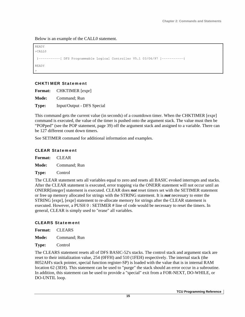
Below is an example of the CALL0 statement.
READY
>CALL0
)-----------[ DFS Programmable Logical Controller V5.1 03/06/97 ]-----------(
READY
>
CHKTIMER Statement
Format: CHKTIMER [expr]
Mode: Command; Run
Type: Input/Output - DFS Special
This command gets the current value (in seconds) of a countdown timer. When the CHKTIMER [expr] command is executed, the value of the timer is pushed onto the argument stack. The value must then be “POPped” (see the POP statement, page 39) off the argument stack and assigned to a variable. There can be 127 different count down timers.
See SETIMER command for additional information and examples.
CLEAR Statement
Format: CLEAR
Mode: Command; Run
Type: Control
The CLEAR statement sets all variables equal to zero and resets all BASIC evoked interrupts and stacks. After the CLEAR statement is executed, error trapping via the ONERR statement will not occur until an ONERR[integer] statement is executed. CLEAR does not reset timers set with the SETIMER statement or free up memory allocated for strings with the STRING statement. It is not necessary to enter the STRING [expr], [expr] statement to re-allocate memory for strings after the CLEAR statement is executed. However, a PUSH 0 : SETIMER # line of code would be necessary to reset the timers. In general, CLEAR is simply used to "erase" all variables.
CLEARS Statement
Format: CLEARS
Mode: Command; Run
Type: Control
The CLEARS statement resets all of DFS BASIC-52's stacks. The control stack and argument stack are reset to their initialization value, 254 (0FFH) and 510 (1FEH) respectively. The internal stack (the 8052AH's stack pointer, special function register-SP) is loaded with the value that is in internal RAM location 62 (3EH). This statement can be used to "purge" the stack should an error occur in a subroutine. In addition, this statement can be used to provide a "special" exit from a FOR-NEXT, DO-WHILE, or DO-UNTIL loop.

Chapter 2: Commands and Statements
TCU Programming Reference 16
An example of the CLEARS statement is provided below.
>LIST
5 STRING 3,1
10 CLEAR : DO
15 PRINT "MULTIPLICATION TEST.",
16 PRINT " YOU HAVE 5 SECONDS FOR EACH PROBLEM. BEGIN!!!"
20 FOR T=1 TO 3
30 N=INT(RND*10) : A=N*T
40 PRINT "WHAT IS",N,"*",T,
50 PUSH 5 : SETIMER 1 : INPUT R
60 CHKTIMER 1 : POP TMR1
70 IF (R=A).AND.(TMR1>0) THEN PRINT "THAT'S CORRECT!" : COR=COR+1
80 IF (R<>A).AND.(TMR1>0) THEN PRINT "THAT'S INCORRECT."
90 IF (TMR1=0) THEN PRINT "YOU WEREN'T QUICK ENOUGH!"
100 NEXT T
105 PRINT "YOU ANSWERED ",COR," PROBLEMS OUT OF ",T-1," CORRECTLY."
110 INPUT "DO YOU WANT TO TRY AGAIN (Y,N)",$(0)
120 AGAIN=(ASC($(0),1)=89)
130 IF NOT(AGAIN) THEN CLEAR S
140 WHILE (AGAIN)
READY
>
Programmer's Note: When the CLEARS statement is LISTed, it will appear as CLEAR S.
In the example above, if you select any character other than a capital Y, the TCU program delivers the following output. DO YOU WANT TO TRY AGAIN (Y,N)y
ERROR: C-STACK - IN LINE 140
140 WHILE (AGAIN)
---------------------X
READY
>
This error occurred because in line 130, the variable AGAIN is false and the stack is cleared with the CLEARS statement. Therefore the stack pointer linking the WHILE statement to the DO statement was reset (cleared).

Chapter 2: Commands and Statements
TCU Programming Reference 17
DATA, READ, RESTORE Statements
Format: DATA -- READ -- RESTORE
Mode: Run
Type: Assign
DATA The DATA statement specifies expressions that may be retrieved by a READ statement. If you use multiple expressions per line, you must separate them with a comma.
READ The READ statement retrieves the expressions that are specified in the DATA statement and assigns the value of the expression to the variable in the READ statement. The READ statement must always be followed by one or more variables. If more than one variable follows a READ statement, they must be separated by a comma.
RESTORE The RESTORE statement "resets" the internal read pointer back to the beginning of the first data line so that the data may be read again.
Below is an example using the DATA, READ, and RESTORE statements.
>LIST
10 FOR A=1 TO 3
20 READ B,C
30 PRINT B,C
40 NEXT A
50 RESTORE
60 READ A,B
70 PRINT A,B
80 DATA 10,20,10/2,20/2,SIN(PI),COS(PI)
READY
>RUN
10 20
5 10
0 -1
10 20
Every time a READ statement is encountered, the next consecutive expression in the DATA statement is evaluated and assigned to the variable in the READ statement. DATA statements can be placed anywhere within a program; they will not be executed nor will they cause an error. DATA statements are considered to be chained together, so that they appear to be one large DATA statement. If at anytime all the DATA has been read and another READ statement is executed, the program is terminated and the message ERROR: NO DATA - IN LINE XX is printed to the console device.

Chapter 2: Commands and Statements
TCU Programming Reference 18
DIM Statement
Format: DIM (Array Var(integer))
Mode: Command; Run
Type: Assignment
The DIM statement reserves storage for matrices (Note that the storage area is first assumed to be zero). Matrices in DFS BASIC 52 can have only one dimension and the size of the dimensioned array cannot exceed 255 elements [for example, DIM (254)]. Once a variable is dimensioned in a program, it cannot be re-dimensioned. An attempt to re-dimension an array will cause an ARRAY SIZE error. If an arrayed variable that has not been dimensioned by the DIM statement is used, BASIC will assign a default value of 10 to the array size. All arrays are set equal to zero when the RUN command, NEW command, or CLEAR statement is executed.
The number of bytes allocated for an array is six times the array size plus one. For example, the line of code DIM A(99) would require 606 bytes of storage [(100+1)*6]. Remember that the first array variable would be A(0) and the last one would be A(99) after executing DIM A(99) to create a 100-element array. The size of a dimensioned array is usually limited by memory size.
Variations
More than one variable can be dimensioned by a single DIM statement [for example, DIM A(10), B(15), A1(20)]. In addition, the integer designating the number of array variables can be represented by a variable [for example, DIM A(NUM), B(NUM+1)], where NUM is a valid array size integer.
The example below shows the error that results when you attempt to re-dimension an array.
>LIST
10 A(5)=23 : REM BASIC ASSIGNS DEFAULT OF 10 TO ARRAY SIZE HERE
20 DIM A(5) : REM ARRAY CANNOT BE REDIMENSIONED
READY
>RUN
ERROR: ARRAY SIZE - IN LINE 20
20 DIM A(5) : REM ARRAY CANNOT BE REDIMENSIONED
---------------X
READY
>
In the example below, the array variable PMP is dimensioned to 6, which allows it to have seven elements (0 to 6).
>LIST
10 DIM PMP(6)
20 FOR X = 0 TO 6
22 PMP(X) = X+1
(continued on next page…)

Chapter 2: Commands and Statements
TCU Programming Reference 19
24 PRINT PMP(X),
30 NEXT X
READY
>RUN
1 2 3 4 5 6 7
DO, UNTIL Statements
Format: DO -- UNTIL [rel expr]
Mode: Run
Type: Control
The DO -- UNTIL instruction provides a means of "loop control" within a DFS BASIC-52 program. The operation of this statement is similar to DO -- WHILE except that all statements between the DO and the UNTIL will be executed until the relational expression following the UNTIL statement is true. DO -- UNTIL and DO -- WHILE statements can be nested.
The first example below illustrates a simple DO -- UNTIL; the second example uses a nested DO -- UNTIL.
Simple DO -- UNTIL
>LIST
5 REM SIMPLE DO -- UNTIL
10 A=0
20 DO
30 A=A+1
40 PRINT A
50 UNTIL A=4
60 PRINT "DONE"
READY
>RUN
1
2
3
4
DONE

Chapter 2: Commands and Statements
TCU Programming Reference 20
Nested DO -- UNTIL
>LIST
5 REM NESTED DO -- UNTIL
10 A=0 : B=0
20 DO : A=A+1 : DO : B=B+1
25 PRINT A,B,A*B
30 UNTIL B=3
40 B=0
50 UNTIL A=2
READY
>RUN
1 1 1
1 2 2
1 3 3
2 1 2
2 2 4
2 3 6
DO, WHILE Statements
Format: DO -- WHILE [rel expr]
Mode: Run
Type: Control
The DO -- WHILE instruction provides a means of "loop control" within a DFS BASIC-52 program. The operation of this statement is similar to DO -- UNTIL except that all statements between DO and WHILE will be executed as long as the relational expression following the WHILE statement is true. DO -- WHILE and DO -- UNTIL statements can be nested.
Simple DO -- WHILE
>LIST
5 REM SIMPLE DO -- WHILE
10 DO
20 A=A+1
30 PRINT A
40 WHILE A<4
50 PRINT "DONE"
READY
>RUN
(continued on next page…)

Chapter 2: Commands and Statements
TCU Programming Reference 21
1
2
3
4
DONE
Nested DO -- WHILE
>LIST
5 REM NESTED DO -- WHILE AND DO -- UNTIL
10 DO : A=A+1 : DO : B=B+1
20 PRINT A,B,A*B
30 WHILE B<3
40 B=0
50 UNTIL A=2
READY
>RUN
1 1 1
1 2 2
1 3 3
2 1 2
2 2 4
2 3 6
END Statement
Format: END
Mode: Run
Type: Control
The END statement terminates program execution. When the END statement is used to terminate the program, the continue command (CONT) cannot be used to resume the program. If you attempt to issue the CONT command after an END statement, a CAN'T CONTINUE error will be printed to the console. The last statement in a DFS BASIC-52 program will automatically terminate program execution if no END statement is used.
Automatically terminated program (no END statement used)
>LIST
5 REM LAST STATEMENT TERMINATION
10 FOR N=1 TO 3
20 PRINT N
READY
>RUN
1
2
3

Chapter 2: Commands and Statements
TCU Programming Reference 22
Program terminated with END statement
>LIST
5 REM END STATEMENT TERMINATION
10 FOR N=1 TO 3
20 GOSUB 100
30 NEXT N
40 END
100 PRINT N : RETURN
READY
>RUN
1
2
3
FOR, TO, NEXT Statements
Format: FOR -- TO -- {STEP} -- NEXT
Mode: Command; Run
Type: Control
The FOR -- TO -- {STEP} -- NEXT statements are used to set up and control loops.
In the examples below:
• The variable "A" represents the name of the index or loop counter. • The value of "B" is the starting value of the index. • The value of "C" is the limit value of the index. • The value of "D" is the increment to the index.
STEP is an optional statement. If the STEP statement and the value "D" are omitted, the increment value defaults to 1 (one). The NEXT statement causes the value of "D" to be added to the index. The index is then compared to the value of "C," which is the limit. If the index is less than or equal to the limit, control will be transferred back to the statement after the FOR statement. Stepping " backwards" (for example, FOR X = 100 TO 1 STEP-1) is permitted in DFS BASIC-52.
FOR -- TO -- {STEP} -- NEXT
>LIST
5 B=0 : C=10 : D=2
10 FOR A=B TO C STEP D
20 PRINT A,
30 NEXT A
READY
>RUN
0 2 4 6 8 10

Chapter 2: Commands and Statements
TCU Programming Reference 23
FOR -- TO -- NEXT (STEP omitted)
>LIST
5 B=0 : C=10
10 FOR A=B TO C
20 PRINT A,
30 NEXT A
READY
>RUN
0 1 2 3 4 5 6 7 8 9 10
FOR -- TO -- {STEP (backwards)} -- NEXT
>LIST
10 FOR X=4 TO 1 STEP -1
20 PRINT X,
30 NEXT X
READY
>RUN
4 3 2 1
In DFS BASIC-52, it is possible to execute the FOR -TO -{STEP}-NEXT statement in Command mode. This makes it possible for the user to do things like display regions of memory by writing a short program right at the command prompt without affecting the written program located in the RAM or ROM.
>FOR V=0 TO 9 : LD@(5005H+V*6) : POP X : PRINT X, : NEXT
300 300 120 90 2378 3224 30 1 0 3
>
GOSUB, RETURN Statements
Format: GOSUB [ln num] -- RETURN
Mode: Run
Type: Control
The GOSUB statement causes DFS BASIC-52 to transfer control of the program directly to the line number [ln num] following GOSUB. Additionally, GOSUB saves the location of the statement following GOSUB onto the control stack.
RETURN is used to "return" control to the statement following the most recently executed GOSUB statement. The GOSUB statement can call another subroutine with another GOSUB statement.
Simple subroutine
>LIST
10 FOR X=1 TO 5
20 GOSUB 100
(continued on next page…)

Chapter 2: Commands and Statements
TCU Programming Reference 24
30 NEXT X
40 END
100 PRINT X,
110 RETURN
READY
>RUN
1 2 3 4 5
READY
>
Nested subroutine
>LIST
10 FOR X=1 TO 5
20 GOSUB 100
30 NEXT X
40 END
100 PRINT X,
110 GOSUB 200
120 RETURN
200 PRINT 2*X
210 RETURN
READY
>RUN
1 2
2 4
3 6
4 8
5 10
If too many GOSUB statements are used without executing a RETURN statement, an error will occur as shown below.
>LIST
10 GOSUB 1000
20 PRINT X,
30 X=X+1
40 GOTO 10
1000 REM line 1000
1010 GOTO 20
1020 RETURN
READY
>RUN
(continued on next page…)

Chapter 2: Commands and Statements
TCU Programming Reference 25
0 1 2 3 4 5 6 7 8 9 10 11 12 13 14 15 16 17 18 19 20
21 22 23 24 25 26 27 28 29 30 31 32 33 34 35 36 37 38 39
40 41 42 43 44 45 46 47 48 49 50 51
ERROR: C-STACK - IN LINE 20
20 PRINT X,
-------------X
READY
>
GOTO Statement
Format: GOTO [ln num]
Mode: Command; Run
Type: Control
The GOTO statement causes BASIC to transfer control directly to the line number [ln num] following the GOTO statement. If a nonexistent line number is entered after GOTO, an INVALID LINE NUMBER error will be returned.
>LIST
10 GOTO 100
20 PRINT "THIS LINE SKIPPED"
100 PRINT "LINE 100"
READY
>RUN
LINE 100
READY
>
Unlike RUN, executing GOTO in Command mode does not clear variable storage space or interrupts unless GOTO is executed after a line has been edited. Executing GOTO after editing a line causes DFS BASIC-52 to clear the variable storage space and all BASIC evoked interrupts. This is necessary because the variable storage and the BASIC program reside in the same RAM memory. Be cautious when using GOTO, because editing a program can destroy variables.
The GOTO statement may also be used in conjunction with the ON statement to produce an ON [expr] GOTO[ln num], [ln num],...[ln num] line of code.

Chapter 2: Commands and Statements
TCU Programming Reference 26
IF, THEN, ELSE STATEMENTS
Format: IF -- THEN -- ELSE
Mode: Run
Type: Control
The IF statement is used to set up a conditional test. The generalized form of the IF--THEN--ELSE statement is as follows:
[ln num] IF [rel expr] THEN [rel expr] or [valid statement] ELSE [rel expr] or [valid statement].
When line 100 is executed in the example below:
• If A is equal to 100, the program returns to the statement following the GOSUB that called this portion of the program.
• If A does not equal 100, A is assigned a value of A + 1.
You can also add multiple commands after each command. See line 110 in the example below.
>LIST
100 IF (A=100) THEN RETURN ELSE A=A+1
110 IF (A=10) THEN B=20:C=30 ELSE B=50:C=60
GOTO is optional when IF is used to transfer control to different line numbers. The following examples would yield the same results.
>LIST
20 IF (INT (A)< 10) THEN GOTO 100 ELSE GOTO 200
30 IF (INT (A)< 10) THEN 100 ELSE 200
Additionally, the THEN statement can be replaced by any valid DFS BASIC-52 statement, as shown below.
>LIST
40 IF (A<>10) THEN PRINT A ELSE 10
50 IF (A<>10) PRINT A ELSE 10
The ELSE statement may also be omitted. If ELSE is omitted, control passes to the next statement. In the example below:
• If A is greater than 10, control is passed to line number 40. • If A does not equal 10, line number 30 is executed.
>LIST
10 TEST_OK=(A>10)
20 IF (TEST_OK) THEN 40
30 PRINT A

Chapter 2: Commands and Statements
TCU Programming Reference 27
Programmer's Note: Notice the use of the logical variable "TEST_OK" in the example above. When using these variables in an IF statement, always place parenthesis around them to distinguish the variable from the rest of the statement. It is good practice to always place parenthesis around the [rel expr] in an IF statement.
INPUT Statement
Format: INPUT
Mode: Run
Type: Input/Output
The INPUT statement allows users to enter data from the console during program execution. This is not often used for process control, because it relies on an operator to enter values in order for the process routine to actually run.
One or more variables can be assigned data with a single INPUT statement, but they must be separated by a comma (for example, INPUT A,B). The INPUT statement causes the printing of a question mark (?) on the console device as a prompt to the operator to input data. If the operator does not enter enough data, DFS BASIC-52 outputs a TRY AGAIN message to the console device. The INPUT statement can be written so that a descriptive prompt is printed to tell the user what to type. The message to be printed is placed in quotes after the INPUT statement. If a comma appears before the first variable on the input list, the question mark prompt character will not be displayed.
Strings can also be assigned with an INPUT statement. Because strings are always terminated with a carriage return (cr), DFS BASIC-52 will prompt the user with a question mark if more than one string input is requested with a single INPUT statement.
Input statement requiring more data (TRY AGAIN generated)
>LIST
5 STRING 11,4
10 INPUT A,B
20 INPUT $(1)
30 PRINT $(1),B,A
READY
>RUN
?5
TRY AGAIN
?5,8
?TEST
TEST 8 5

Chapter 2: Commands and Statements
TCU Programming Reference 28
Input statement with descriptive prompt
>LIST
5 STRING 11,4
10 INPUT "ENTER A 4 LETTER WORD: ",$(1),$(0)
20 INPUT ,B,A
30 PRINT $(0),$(1),B,A
READY
>RUN
ENTER A 4 LETTER WORD: TEST
?ZERO
25,965
ZERO TEST 25 965
Input statement using strings
>LIST
10 STRING 100,10
20 INPUT "NAME(CR), AGE - ",$(1),A
30 PRINT "HELLO ",$(1),", YOU ARE ",A, "YEARS OLD."
READY
>RUN
NAME(CR), AGE - FRED
?15
HELLO FRED, YOU ARE 15 YEARS OLD.
LD@ Statement
Format: LD@ [expr]
Mode: Command; Run
Type: Input/Output – DFS Special
DFS BASIC-52 reserves 1008 bytes of non-volatile memory starting at location 5000H. This memory is reserved for the purpose of storing and retrieving floating point set point variables in battery backed-up (non-volatile) memory. When the RTU is powered down for any reason, previously assigned set points are allowed to recover to their last set value. Up to 168 basic variables (six bytes per variable) can be stored in non-volatile memory using the ST@ command (discussed on page 49) and retrieved using LD@. A table listing all of the memory locations is provided in Appendix B: Free External Memory Storage Map.
LD@ allows the user to retrieve floating-point numbers that were saved with ST@. The expression [expr] following LD@ specifies where the number is stored. After executing LD@, the number is placed on the argument stack. The POP command must be used to retrieve the value from the argument stack and assign it to a variable.
Programmer's Note: ST@ and LD@ statements point to the least significant byte of the stored number in accordance with the floating-point format. Hence, ST@ (5005H) would save the number in locations 5000H, 5001H… 5005H.

Chapter 2: Commands and Statements
TCU Programming Reference 29
>LIST
10 REM RETRIEVING A TEN ELEMENT ARRAY
100 FOR X=0 TO 9
110 LD@ 5005H+6*X : POP SETPNT(X)
120 NEXT X
READY
>RUN
READY
>
Memory Image Updating via PLC Editor
Values can also be transferred to and from the TCU’s non-volatile memory locations using PLC Editor. This is an advanced feature used to send set point variables to the TCU over a radio link. At times, the amount of real and virtual I/O exceeds the 15-module capacity of the single RTU. With the Memory Image Updating feature, additional set points can be communicated between the central computer and the TCU.
Note, however, that memory image updating will not work with the TCU if it is connected to an RTU that is operating with a PLC. This is due to both the PLC and TCU responding to module "Q.”
PLC Editor is a separate utility that works in conjunction with the HyperTAC II software. Refer to the onscreen help for PLC Editor for information on using this application.
Floating Point Format
BASIC-52 stores all floating-point numbers in a normalized packed Binary Coded Decimal (BCD) format with an offset binary exponent requiring six bytes of storage. In the following explanation, the value of PI (3.1415926) is used as an example and is stored at memory location X.
If we were to save the value of PI into memory location 5005H using the ST@ command (where X would now equal 5005H), the line of code would read:
PUSH PI : ST@5005H
Byte 5005H would contain the Exponent value (81H), and byte 5000H would contain the most significant two digits (31H).
Location Value Description X 81H Exponent
81H = 10**1; 82H = 10**2; 83H = 10**3; etc.
80H = 10**0; 7FH = 10**-1; 7EH = 10**-2; etc.
The number ZERO is represented with a ZERO exponent.
X-1 00H Sign Bit 00H = Positive; 01H = Negative

Chapter 2: Commands and Statements
TCU Programming Reference 30
Other bits are used as temporary positions only during a calculation
X-2 26H Least significant two digits
X-3 59H Next least significant two digits
X-4 41H Next most significant two digits
X-5 31H Most significant two digits
LET Statement
Format: LET
Mode: Command; Run
Type: Assignment
The LET statement is used to assign a variable to the value of an expression. The generalized form of LET is:
LET[var] = [expr]
Note that the = sign used in the LET statement is not an equality operator, but rather a "replacement" operator. The statement should be read as:
A is replaced by A plus one
The word LET is always optional, (that is, LET A = 2 is the same as A = 2). When LET is omitted, the LET statement is called an IMPLIED LET. This manual uses the word LET to refer to both the LET statement and the IMPLIED LET statement.
The LET statement is also used to assign a string variable, (for example, LET $(1)="THIS IS A STRING"). Before strings can be assigned, the STRING statement must be executed. Failure to do so will generate a MEMORY ALLOCATION ERROR.
Special function operators can also be assigned by the LET statement, [for example, LET XBY(2000H)=5AH, or LET DBY(25)=XBY(1000)].
LET Statement
>LIST
10 LET A = 10*SIN(B)/100
20 LET A = A + 1
READY
>
IMPLIED LET Statement
>LIST
10 A = 10*SIN(B)/100
20 A = A + 1
READY

Chapter 2: Commands and Statements
TCU Programming Reference 31
>
MENU Statement
The MENU statement is used to manipulate the TCU’s LCD in a background mode. Because the BASIC routine may take seconds to update the display, the MENU statement allows menu pages to be predefined and the display to be updated from a background keyboard routine. MENU has various command line parameters that cover multiple functions.
You can define up to 16 menus. Each menu is one full 4x20 LCD screen. You can envision this as a stack of 16 pages each with four lines of text. Each line can be up to 20 characters long.
MENU
Format: MENU
Mode: Command; Run
Type: Input/Output; DFS Special
The MENU statement, when used without additional parameters, performs dual functions. It may:
• Pass a value off the argument stack to the LCD control routine. • Take the value of the active menu item from the LCD control routine and place it on the argument
stack. If the MENU statement is used without additional parameters, but is preceded by the PUSH [n] statement (where n is between 1 and 16), it forces the nth menu page to be displayed on the LCD (see PUSH statement, page 45). If a value outside the 1 to 16 range is on the top of the argument stack when the MENU statement is executed, an INVALID MENU OPTION error appears on the console device and program execution is stopped or restarted.
If the MENU statement is used without additional parameters and no value has been “PUSHed,” the menu page and the line currently displayed on the LCD are placed on the argument stack. The POP statement (see page 39) must be used immediately following the MENU statement in order to retrieve the menu page and line from the argument stack.
In the example below, three menu items (0, 1, and 2) are defined. When the program is executed, menu item 1 “ALARMS” is displayed on the LCD.
Menu statement (proceeded by PUSH)
>LIST
5 SYSTIME : POP SC,MN,HR,DY,DT,MO,YR
10 MENU (1,1)=” Time -“,HR,”:”,MN
12 MENU (1,2)="ALARMS"
14 MENU (1,3)="CONFIGURATION"
20 PUSH 1 : MENU
30 MENU ON
READY
>RUN
READY

Chapter 2: Commands and Statements
TCU Programming Reference 32
>
This example shows how the Menu statement is used to read the page and line that have been selected on the TCU's LCD.
Menu statement (followed by POP)
2016 Menu On
2018 Menu: pop Pg,Ln : REM Get page and line selected on LCD
MENU ON
Format: MENU ON
Mode: Command; Run
Type: Control; DFS Special
Using the ON parameter with the MENU statement enables the background LCD control routine to display menu items defined and selected by the foreground program. While the MENU is ON, the following have no affect:
• The PRINT@ statement • The LED DS4, which is the LCD backlight
Refer to the examples for the other MENU statements to see how MENU ON can be used in a DFS BASIC-52 program.
MENU OFF
Format: MENU OFF
Mode: Command; Run
Type: Control; DFS Special
Using the OFF parameter with the MENU statement causes menu display operations to be suspended. While the MENU is OFF:
• The PRINT@ statement can be used to print up to 20 characters to the LCD at a time. • The LED DS4, which is the LCD backlight, may also be turned on and off from the program using
the DGOUT statement (refer to the DGOUT statement for specifics on LED controls).

Chapter 2: Commands and Statements
TCU Programming Reference 33
In this example, the menu display is turned off and the TCU’s splash screen is displayed.
REM Splash:
6814 Menu Off
6816 Print Using(0), : REM Clear screen
6818 For I=1 to 4:print@ " ":next I
6820 Print@" Pump Controller" : REM display splash screen
6822 Print@" "
6824 Print@" Proc ID=",PgID : ReM with program ID
6826 Print@" Version=",PgVer : ReM and version
6828 Return
MENU CLR
Format: MENU ON
Mode: Command; Run
Type: Control; DFS Special
Using the CLR parameter with the MENU statement, instructs the LCD control routine to clear the active menu list. If the MENU is still ON, the display defaults to MENU 1.
The example below shows the appropriate sequence of statements to use to prevent the menu items from flashing on and off or changing erratically while the MENU is being turned ON and OFF, CLRed, and reset.
> MENU (1,1)=“TEST MENU 0”
> MENU (2,1)=“TEST MENU 1”
> MENU (3,1)=“TEST MENU 2”
> MENU ON : REM USING THE ARROW KEYS, SCROLL THROUGH TO ‘TEST MENU 1’
> MENU OFF : REM ‘TEST MENU 1’ WILL REMAIN VISIBLE ON THE LCD
> MENU (4,1)=“TEST OVER 3”
> MENU ON : REM ‘TEST MENU 0’ WILL BE DISPLAYED FOLLOWED BY MENU ITEMS 1, 2, 3
MENU (define menu pages)
Format: MENU (page, line) = expr
Mode: Command; Run
Type: Assignment; DFS Special
Parameters:
page := integer 1-16 indicating menu page to be assigned
line := integer 1-4 indicating the line on the above page to be assigned
expr := combinations of constants and variables of strings and/or numerical values
This variation of the MENU statement is used to define the menu pages. The list of expressions (expr) to the right of the equals sign can be any valid expressions described in the PRINT command. The page and line variables specify which page and line to modify. Once any line on a page has been defined, that page

Chapter 2: Commands and Statements
TCU Programming Reference 34
is accessible via the TCU’s left and right arrow keys until the MENU CLR command is executed. Pressing the right arrow key displays the next menu page. Pressing the left arrow key displays the previous menu page.
In the example below, two menu pages are set up with two lines on each page. Menu page 1, line 2 & 3, and menu page 2, line 2 & 3, are defined. When the program is executed, menu page 1 is displayed on the LCD.
5 SYSTIME : POP SC,MN,HR,DY,DT,MO,YR
10 MENU (1,2)=” TCU TEST PROGRAM”
20 MENU (1,3)=” Time -“,HR,”:”,MN
30 MENU (2,2)=” ALARMS”
40 MENU (2,3)=” CONFIGURATION”
50 PUSH 1 : MENU
60 MENU ON
MENU INPUT
Format: MENU INPUT [$(]default[)], lolimit, hilimit
Mode: Command; Run
Type: Input; DFS Special
Parameters:
default := the default starting value of the input
lolimit := the lowest value allowed to be input
hilimit := the highest value allowed to be input
The MENU INPUT statement allows the background menu routine to update predefined menus with number or character string input.
When used for numeric input, the specified default value is initially displayed on the LCD at the current location. Numeric entry is accepted from the keypad. When the Enter key is pressed, the value entered is compared against the low and high limits and, if valid, that value is returned. Otherwise, the default value is returned.
For character string input, the default value must be specified as a string array “$(n)”. When this is done, the first value displayed is the string in the $ string array defined by the default variable. When the up and down arrow keys are pressed, the next or previous string is displayed until the lolimit or hilimit is reached. Pressing the Enter key causes the current value to be returned.

Chapter 2: Commands and Statements
TCU Programming Reference 35
In the example below, two pages are defined. Menu page 2 allows configuration modification of two items stored in a configuration array.
10 STRING 200,10: $(1)=”Floats”: $(2)=”4/20mA” REM Define strings
20 SYSTIME : POP SC,MN,HR,DY,DT,MO,YR REM Get the time
30 MENU (1,2)=” TCU TEST PROGRAM” REM Set up
40 MENU (1,3)=” Time -“,HR,”:”,MN REM page1
50 MENU (2,2)=”Xducer type = “,$(CFG(1)) REM Set up
60 MENU (2,3)=” No. pumps = “,CFG(2) REM page 2
95 MENU ON
100 DO
110 DO: C=GET UNTIL C=13 REM Wait for Enter key
120 MENU: POP P,L REM get page and line
0 REM If we are on page 2 line 2, input string
130 IF ((P=2) .AND. (L=2)) THEN MENU INPUT $(CFG(1)),1,2: POP I: CFG(1)=I
0 REM If we are on page 2 line 3, input numeric
140 IF ((P=2) .AND. (L=3)) THEN MENU INPUT CFG (2),1,3: POP I: CFG(2)=I
200 UNTIL 0
MENU PLOT
Format: MENU PLOT (page, top, bottom, left, right) = expr
Mode: Command; Run
Type: Output; DFS Special
Parameters:
page := the menu page that the plot is to be on
top := the top line to be used by the plot
bottom := the bottom line to be used by the plot
left := the left column to be used by the plot
right := the right column to be used by the plot
expr := value to plot (0.00 to 1.00)
This variation of the MENU statement allows trend graphs to be plotted on the LCD display. Graphs are displayed by sending special bar characters to the LCD. The maximum graph would have 20 columns each of which would have 28 possible levels.
The page variable defines the menu page on which the graph is to be placed. The top, bottom, left, and right variables define a box that the graph is to be placed in. Each time the MENU PLOT routine is executed for a specific page, the entire graph is shifted to the left, and the expression’s (expr) new value is graphed into the right column.

Chapter 2: Commands and Statements
TCU Programming Reference 36
In the example below, a bar graph is made on menu page 1 using the entire LCD display area with the height of each bar equal to its column number.
>10 MENU ON REM Turn MENUing on
>20 FOR I=0 TO 20 REM For each column on display
>30 MENU PLOT(1,1,4,1,20)=I/20 REM graph a column whose height = its column number
>40 NEXT I
ON Statement
Format: ON [expr] GOSUB [ln num], [ln num],...[ln num]
ON [expr] GOTO [ln num], [ln num],...[ln num]
Mode: Run
Type: Control
The ON statement provides "conditional branching" options within the constructs of a DFS BASIC-52 program. All properties of the GOTO and GOSUB statements are the same when used with the ON statement as when they are used independently of the ON statement.
The value of the expression following ON is the number in the GOSUB/GOTO line number list to which control will be transferred. The expression’s value must always be an integer equal to or greater than zero, but less than the number of items in the line number list. The first line number in the GOSUB/GOTO list is always designated when the expression is equal to zero.
Notice that the number of line numbers listed (four in both examples) is equal to the number of values the X value can hold (0-3 is four digits).
• If X is equal to zero, control is transferred to line number 100. If X is equal to one, control is transferred to line number 200, etc.
• If X is less than zero, a BAD ARGUMENT error will be generated. • If X is greater than the GOSUB/GOTO line number list, a BAD SYNTAX error will be generated.
The number of line numbers in the list is only restricted by the number of line numbers that can be entered after GOSUB/GOTO before the 79-character limit of a line of code is reached.
See the next page for examples of using the ON statement with GOSUB and GOTO.

Chapter 2: Commands and Statements
TCU Programming Reference 37
ON with GOSUB >LIST
10 FOR X=0 TO 3
20 ON X GOSUB 100,200,300,400
30 NEXT X
40 END
100 PRINT "100 ",
110 RETURN
200 PRINT "200 ",
210 RETURN
300 PRINT "300 ",
310 RETURN
400 PRINT "400 ",
410 RETURN
READY
>RUN
100 200 300 400
READY
>
ON with GOTO >LIST
10 INPUT "ENTER A NUMBER (0-3)",X
20 IF (INT(X)<0).OR.(INT(X)>3) GOTO 10
30 ON X GOTO 100,200,300,400
100 PRINT "YOU ENTERED A '0'"
102 END
200 PRINT "YOU ENTERED A '1'"
202 END
300 PRINT "YOU ENTERED A '2'"
302 END
400 PRINT "YOU ENTERED A '3'"
402 END
READY
>RUN
ENTER A NUMBER (0-3)5
ENTER A NUMBER (0-3)2
YOU ENTERED A '2'
READY
>

Chapter 2: Commands and Statements
TCU Programming Reference 38
ONERR Statement
Format: ONERR [ln num]
Mode: Run
Type: Control
With the ONERR statement, the programmer can handle any arithmetic errors that may occur during program execution. The only errors that can be “trapped” by ONERR are:
• ARITH. OVERFLOW • ARITH. UNDERFLOW • DIVIDE BY ZERO • BAD ARGUMENT
If an arithmetic error occurs after the ONERR statement is executed, the DFS BASIC-52 interpreter will pass control to the line number following the ONERR statement. The programmer can handle the error condition in any manner suitable to the particular application. Typically, ONERR should be viewed as an easy way to handle errors that occur when the user provides inappropriate data to an INPUT statement.
With ONERR, the programmer has the option of determining what type of error occurred. This is done by examining external memory location 257 (101H) after the error condition is trapped. The error codes are as follows:
10=DIVIDE BY ZERO
20=ARITH. OVERFLOW
30=ARITH. UNDERFLOW
40=BAD ARGUMENT
This location may be examined by using an XBY(257) statement.
PH0., PH1., PH0.#, PH1.# Statements
Format: PH0.; PH1.; PH0.#; PH1.#
Mode: Command; Run
Type: Input/Output
The PH0. and PH1. statements have the same functionality as the PRINT statement except that the values are printed out in a hexadecimal format.
• The PH0. statement suppresses two leading zeros if the number to be printed is less than 255 (0FFH). • The PH1. statement always prints out four hexadecimal digits.
When PH0. or PH1. is used to direct an output, the character "H" is always printed after the number and the values printed are always truncated integers. If the number to be printed is not within the range of valid integers [that is, between 0 and 65535 (0FFFFH), inclusive], DFS BASIC-52 defaults to the normal mode of print. When this happens, no "H" is printed out after the value.

Chapter 2: Commands and Statements
TCU Programming Reference 39
Since integers can be entered in either decimal or hexadecimal form, the statements PRINT, PH0., and PH1. can be used to perform decimal to hexadecimal conversion. All comments that apply to the PRINT statement apply to the PH0. and PH1. statements. PH0.# and PH1.# do the same thing as PH0. and PH1. respectively, except that the output is directed to the list device instead of the console device.
Examples
>PH0. 2*2
04H 0004H
>PH1. 2*2
153
>PRINT 99H
64H
>PH0. 100
>PH0. 1000
3E8H 03E8H
>PH1. 1000
1000
>P. 3E8H
03H
>PH0. 3.1415926
POP Statement
Format: POP [var]
Mode: Command; Run
Type: Assignment
With the POP statement, the top of the argument stack is assigned to the variable following POP and the argument stack is "POPped" (that is, incremented by 6). Values can be placed on the stack by:
• The PUSH statement • Telemetry input statements DGIN, ANIN or SYSTIME • A DFS Special command like CHKTIMER.
If a POP statement is executed and no number is on the argument stack, an A-STACK error is returned.
Variation
More than one variable can be “POPped” off the argument stack with a single POP statement. The variables are simply followed by a comma (that is, POP [var],[var],........[var]).

Chapter 2: Commands and Statements
TCU Programming Reference 40
POP statement with single variable
>LIST
5 REM SETTING AND WATCHING A TIMER
10 PUSH 10 : SETIMER 1
20 CHKTIMER 1 : POP TD1
30 IF (TD1<>X) THEN PRINT TD1,
40 X=TD1
50 IF (TD1<>0) THEN GOTO 20
READY
>RUN
10 9 8 7 6 5 4 3 2 1 0
READY
>
POP Statement with multiple variables
>LIST
5 REM VIEW SYSTEM STATUS
10 SYSCHECK : POP EFLT,RFLT,MFLT
20 PRINT EFLT,RFLT,MFLT
READY
>RUN
0 1 65535
READY
>
The PUSH and POP statements can be used to avoid the global variable problems so often encountered in BASIC programs. This problem arises because in BASIC, the "main" program and all subroutines used by the main program are required to be the same variable names (that is, global variables). It is not always convenient to use the same variables in a subroutine as in the main program, and you often see programs re-assign a number of variables (for example, A=Q) before a GOSUB statement is executed. If some variable names are reserved just for subroutines (for example, S1,S2), values can be passed to these variables by using the stack instead of the LET statement. This also helps avoid errors caused by improperly assigning values to global variables within the subroutines. See the example on the next page.

Chapter 2: Commands and Statements
TCU Programming Reference 41
Using POP and PUSH with global variables
>LIST
10 FOR X=1 TO 5
20 PUSH X
30 GOSUB 100
40 POP B,A
50 PRINT A,B
60 NEXT X
70 END
100 POP S1
110 S2=SQR(S1)
120 PUSH S1,S2
130 RETURN
READY
>RUN
1 1
2 1.4142136
3 1.7320508
4 2
5 2.236068
READY
>
PRINT or P. or ? Statement
Format: PRINT; P.; ?
Mode: Command; Run
Type: Input/Output
The PRINT statement directs DFS BASIC-52 to output to the console device. The value of expressions, strings, literal values, variables, or test strings can be printed. The various forms can be combined in the print list by separating them with commas. If the list is terminated with a comma, the carriage return/line feed will be suppressed. Note that P. and ? are “shorthand” notations for PRINT.
When PRINT is executed, values are printed on the same line with two spaces between them. A PRINT statement with no arguments causes a carriage return/line feed sequence to be sent to the console device.
>PRINT 10*10,3*3
100 9
>PRINT "DFS-51"
DFS-51
>PRINT 5,1E3
5 1000

Chapter 2: Commands and Statements
TCU Programming Reference 42
Special Print Formatting Statements
CLEAR SCREEN & RETURN HOME Two print statements that are very useful in formatting VT100 display screens use the CHR( ) string operator explained in Chapter 3: Operators and Expressions. Many times, it is helpful to be able to clear the display screen, or send the cursor to the “home” position in the upper left corner of the display screen.
To clear the screen, use this statement in Command or Run mode:
PRINT CHR(27),”[2J”,
To position the cursor “home,” use this statement in Command or Run mode:
PRINT CHR(27),”[H”,
CR The CR function is interesting and unique to DFS BASIC-52. When CR is used in a PRINT statement (followed by a comma), it will force a carriage return, but no line feed. This can be used to create one line on a CRT device that is repeatedly updated.
Print formatted with CR (followed by a comma)
>LIST
10 FOR X=1 TO 5
20 PRINT X, CR ,
30 NEXT X
READY
>RUN
5
READY
>
Print statement formatted with CR (no comma)
>LIST
10 FOR X=1 TO 5
20 PRINT X, CR
30 NEXT X
READY
>RUN
1
2
3
4
5
READY
>

Chapter 2: Commands and Statements
TCU Programming Reference 43
SPC([expr]) The SPC function is used in the PRINT statement to cause DFS BASIC-52 to output the number of spaces in the SPC argument [expr]. The following example shows how SPC can be used to place an additional 5 spaces between the A and B over and above the two that would normally be printed.
PRINT A,SPC(5),B
A B
TAB([expr]) Using TAB in the PRINT statement enables you to specify the exact location where data is to be printed on the output device. TAB([expr]) tells DFS BASIC-52 which position to begin printing the next value in the print list. If the print head or cursor is on or beyond the specified TAB position, DFS BASIC-52 ignores the TAB function.
PRINT statement formatted with TAB
PRINT TAB(5),"X",TAB(10),"Y"
X Y
PRINT TAB(20),”A”,CR,TAB(5),”B”
B A
USING(special characters) USING tells DFS BASIC-52 in what format to display the printed values. Because DFS BASIC-52 "stores" the desired format after the USING function is executed, all outputs following a USING statement will be in the format evoked by the last executed USING function. Therefore, the USING Function does not need to be executed within every PRINT statement unless the programmer wants to change the format. Note that U. is a "shorthand" notation for USING. The options for USING are as follows:
PRINT USING(Fx) – This forces DFS BASIC-52 to output all numbers using the floating-point format. The value of x determines how many significant digits will be printed. The maximum value for x is eight. If x equals zero, DFS BASIC-52 will not output any trailing zeros. In this case, the number of digits will vary depending on the number being printed. DFS BASIC-52 will always output at least three significant digits even if x is one or two. This format always "aligns" the decimal points when printing series of numbers, which makes displayed columns of numbers easy to read.
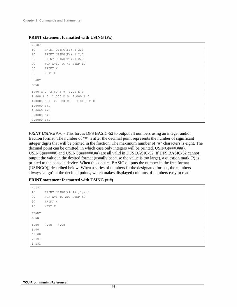
Chapter 2: Commands and Statements
TCU Programming Reference 44
PRINT statement formatted with USING (Fx)
>LIST
10 PRINT USING(F3),1,2,3
20 PRINT USING(F4),1,2,3
30 PRINT USING(F5),1,2,3
40 FOR X=10 TO 40 STEP 10
50 PRINT X
60 NEXT X
READY
>RUN
1.00 E 0 2.00 E 0 3.00 E 0
1.000 E 0 2.000 E 0 3.000 E 0
1.0000 E 0 2.0000 E 0 3.0000 E 0
1.0000 E+1
2.0000 E+1
3.0000 E+1
4.0000 E+1
PRINT USING(#.#) - This forces DFS BASIC-52 to output all numbers using an integer and/or fraction format. The number of "#" 's after the decimal point represents the number of significant integer digits that will be printed in the fraction. The maximum number of "#" characters is eight. The decimal point can be omitted, in which case only integers will be printed. USING(###.###), USING(######) and USING(######.##) are all valid in DFS BASIC-52. If DFS BASIC-52 cannot output the value in the desired format (usually because the value is too large), a question mark (?) is printed to the console device. When this occurs, BASIC outputs the number in the free format [USING(0)] described below. When a series of numbers fit the designated format, the numbers always "align" at the decimal points, which makes displayed columns of numbers easy to read.
PRINT statement formatted with USING (#.#)
>LIST
10 PRINT USING(##.##),1,2,3
20 FOR X=1 TO 200 STEP 50
30 PRINT X
40 NEXT X
READY
>RUN
1.00 2.00 3.00
1.00
51.00
? 101
? 151

Chapter 2: Commands and Statements
TCU Programming Reference 45
PRINT USING(0) - This format allows DFS BASIC-52 to determine what format to use.
• If the number is between 0.1 and 99999999, or -0.1 and -99999999, the display is in integers and fractions.
• If it is out of this range, the display defaults to the USING(F0) format.
Leading and trailing zeros are always suppressed. After reset, DFS BASIC-52 is placed in the USING(0) format.
PRINT@ or P.@ or ?@ Statement
Format: PRINT@; P.@; ?@
Mode: Command; Run
Type: INPUT/OUTPUT
The PRINT@ (shorthand notation: P.@ and ?@) statement performs the same function as the PRINT statement except that the output is directed to the TCU’s LCD (when the MENU function is turned OFF) instead of the console device. Remember that the LCD is limited to four lines of 20 characters each. Any print information exceeding 20 characters will truncate on the LCD, so that only the first 20 characters are displayed.
PRINT# or P.# or ?# Statement
Format: PRINT#; P.#; ?#
Mode: Command; Run
Type: Input/Output
The PRINT# (shorthand notation: P.# and ?#) statement performs the same function as the PRINT statement except that the output is directed to the list device instead of the console device. Before the PRINT# statement is used, the BAUD rate to the list device must be initialized by the statement BAUD[expr]. All comments that apply to the PRINT statement apply to the PRINT# statement.
PUSH Statement
Format: PUSH [expr]
Mode: Command; Run
Type: Assignment
This statement provides a simple means of passing parameters to the telemetry output statements DGOUT and ANOUT. Additionally, the PUSH (and POP) statements can be used to "swap" variables and pass parameters to and from DFS Special routines such as the SETIMER and SYSTIME SET. The arithmetic expression, or expressions, following the PUSH statement are evaluated and then sequentially placed on the argument stack. The last value “PUSHed” (see PUSH statement, page 45) onto the argument stack will be the first value “POPped” (see the POP statement, page 39) off the argument stack.

Chapter 2: Commands and Statements
TCU Programming Reference 46
Variations:
A single PUSH statement can be used to push multiple expressions onto the argument stack by separating each expression with a comma (PUSH [expr],[expr],........[expr]). The last value pushed onto the argument stack will be the last expression [expr] encountered in the PUSH statement.
PUSH used to swap variables
>LIST
5 REM SWAPPING VARIABLES
10 A=10
20 B=20
30 PRINT A,B
40 PUSH A,B
50 POP A,B
60 PRINT A,B
READY
>RUN
10 20
20 10
READY
>
PUSH used to set system time
>LIST
5 REM SETTING THE SYSTEM TIME
10 HR=5 : MN=20 : SC=13
20 YR=1997 : MO=5 : DT=12
30 DY=2
40 PUSH SC,MN,HR,DY,DT,MO,YR
50 SYSTIME SET
60 SYSTIME
70 POP A,B,C,D,E,F,G
80 PRINT A,B,C,D,E,F,G
READY
>RUN
13 20 5 2 12 5 1997
READY
>
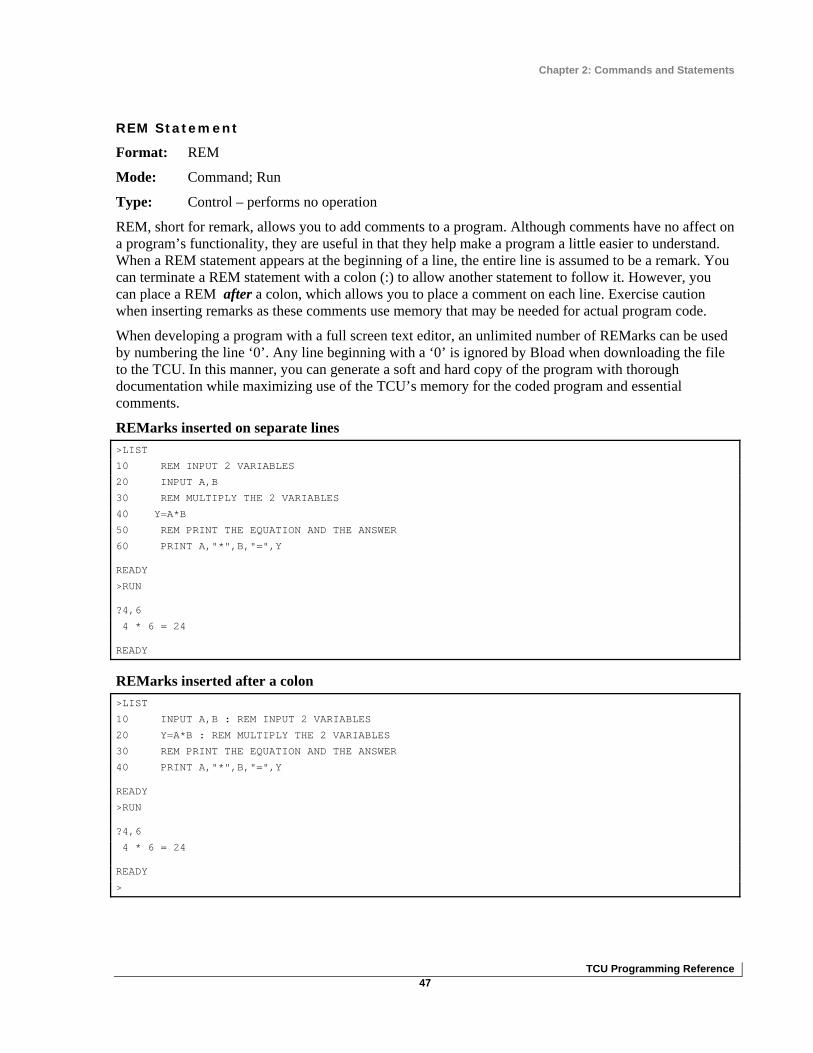
Chapter 2: Commands and Statements
TCU Programming Reference 47
REM Statement
Format: REM
Mode: Command; Run
Type: Control – performs no operation
REM, short for remark, allows you to add comments to a program. Although comments have no affect on a program’s functionality, they are useful in that they help make a program a little easier to understand. When a REM statement appears at the beginning of a line, the entire line is assumed to be a remark. You can terminate a REM statement with a colon (:) to allow another statement to follow it. However, you can place a REM after a colon, which allows you to place a comment on each line. Exercise caution when inserting remarks as these comments use memory that may be needed for actual program code.
When developing a program with a full screen text editor, an unlimited number of REMarks can be used by numbering the line ‘0’. Any line beginning with a ‘0’ is ignored by Bload when downloading the file to the TCU. In this manner, you can generate a soft and hard copy of the program with thorough documentation while maximizing use of the TCU’s memory for the coded program and essential comments.
REMarks inserted on separate lines >LIST
10 REM INPUT 2 VARIABLES
20 INPUT A,B
30 REM MULTIPLY THE 2 VARIABLES
40 Y=A*B
50 REM PRINT THE EQUATION AND THE ANSWER
60 PRINT A,"*",B,"=",Y
READY
>RUN
?4,6
4 * 6 = 24
READY
REMarks inserted after a colon >LIST
10 INPUT A,B : REM INPUT 2 VARIABLES
20 Y=A*B : REM MULTIPLY THE 2 VARIABLES
30 REM PRINT THE EQUATION AND THE ANSWER
40 PRINT A,"*",B,"=",Y
READY
>RUN
?4,6
4 * 6 = 24
READY
>

Chapter 2: Commands and Statements
TCU Programming Reference 48
The following will not work because the entire line would be interpreted as a REMark, so the PRINT statement would not be executed:
>LIST
10 REM PRINT THE NUMBER : PRINT A
Programmer's Note: There is a special function carried out with the REM statement. When typing directly in the TCU’s RAM, the following command (in all capital letters) can be entered to prevent the contents of the RAM from being erased when power is cycled to the TCU: 0 REM DEBUG.
RROM Statement
Format: RROM {integer}
Mode: Command; Run
Type: Control
RROM, which stands for RUN ROM, is used to select and execute a program in the EPROM file {1-8}. The integer after the RROM statement selects which program in the EPROM file is to be executed. If no integer is entered, the program in ROM location 1 is executed by default.
In Command mode, RROM 2 would be equivalent to typing ROM 2 then RUN. However, RROM {integer} is a statement, which means that a program that is already executing can actually force the execution of a completely different program located in the EPROM file. This gives you the ability to "change programs" on the fly.
If a RROM statement is executed in a running program, and an invalid integer is entered (say 6 programs are contained in the EPROM file and the program executes RROM 8), no error is generated. DFS BASIC-52 simply executes the statement following the RROM statement.
Every time the RROM statement is executed, all variables and strings are set equal to zero. As a result, variables and strings cannot be passed from one program to another by using the RROM statement. Note, however, that modules defined with the DEFMOD statement are not cleared from memory location blocks 6000H to 7000H. Refer to the XBY statement – Module I/O Memory manipulation section (pages 9-5 and 9-6) of the PLC001/SCU001 Operations Guide for more information (DFS personnel only).
SETIMER Statement
Format: SETIMER [integer]
Mode: Command; Run
Type: Input/Output – DFS Special
This command sets a countdown timer for a specific numbers of seconds. The value in seconds must be an integer “PUSHed” (see PUSH statement, page 45) onto the argument stack immediately before using the SETIMER statement. The number of seconds can be 1 to 65535 and can be represented with a variable or arithmetic expression. There can be 128 different countdown timers (0-127). This command is always used in conjunction with the CHKTIMER command.

Chapter 2: Commands and Statements
TCU Programming Reference 49
Both the SETIMER and CHKTIMER commands utilize the argument stack. An integer value up to 65535 is “PUSHed” onto the argument stack. The SETIMER command retrieves this value from the argument stack and stores it into the timer designated after the SETIMER command.
In the following example, if pump #1 is not called (PC(1) = FA), timer 1 is set for 2 minutes (120 seconds). Once pump #1 is called, timer 1 is no longer reset and begins timing out. The CHKTIMER command is used to retrieve the current value of the counting timer and place the value on the argument stack. This value is assigned to the TD(1) variable using the POP command. Once the timer has expired [TD(1)=0], if pump #1 is not running [PS(1) = FA], the pump #1 starter fault alarm [PF(1)] is set true. Once the pump is not called and the timer is reset, or pump #1 is running, the starter fault alarm clears. This same test is performed for pump #2 and pump #3 with the use of the FOR -- NEXT loop and the utilization of arrays. Typically, the pump calls would be sent out through telemetry using DGOUT statements; the pump statuses would be monitor points retrieved through telemetry using DGIN statements; and the fault statuses would be output using DGOUT statements.
>LIST
10 DIM PC(NPMP+1), PS(NPMP+1), PF(NPMP+1), TD(NPMP+1)
20 REM PC=PUMP CALL, PS=PUMP STATUS, PF=PUMP FAULT, TD=TIME DELAY
100 FOR X=1 TO 3
110 IF NOT(PC(X)) THEN PUSH 120 : SETIMER X
120 CHKTIMER X : POP TD(X)
130 PF(X)=(TD(X)=0).AND.NOT(PS(X))
140 NEXT X
ST@ Statement
Format: ST@ [expr]
Mode: Command; Run
Type: Input/Output – DFS Special
DFS BASIC-52 reserves 1008 bytes of non-volatile memory (starting at location 5000H) for the purpose of storing and retrieving floating point set point variables in battery backed-up (non-volatile) memory. This is useful in programming when the RTU is powered down for any reason, because it allows previously assigned set points to recover their last set value. Up to 168 basic variables (six bytes per variable) can be stored in non-volatile memory using the ST@ command and retrieved using the LD@ command.
ST@ lets you specify where in non-volatile memory DFS BASIC-52 floating point numbers are to be stored. The expression [expr] following ST@ specifies the address where the number is to be stored. The number to be stored must be “PUSHed” (see PUSH statement, page 45) onto the argument stack prior to the ST@ command being executed.
See LD@ command for additional information on page 28.

Chapter 2: Commands and Statements
TCU Programming Reference 50
STOP Statement
Format: STOP
Mode: Run
Type: Control
The STOP statement allows you to break program execution at specific points in a program. After a program is STOPped, variables can be displayed and/or modified. Program execution can be resumed with the CONTinue command. The purpose of the STOP statement is to allow for easy program "debugging."
Notice in the example on the next page that the line number printed out after the STOP statement is executed in the line number following the STOP statement, not the line number that contains the STOP statement.
>LIST
10 FOR X=1 TO 100
20 PRINT X,
30 IF (X=4) STOP
40 IF (X=30) END
50 NEXT X
READY
>RUN
1 2 3 4 STOP - IN LINE 40
READY
>X=25
>CONT
26 27 28 29 30
READY
>
STRING Statement
Format: STRING [expr],[expr] statement
Mode: Command; Run
Type: Assignment
The STRING statement is used to allocate memory for strings.
• The first expression in the STRING statement is the total number of bytes you want to allocate for string storage.
• The second expression denotes the maximum number of bytes (or characters) that are in each string.
These two numbers determine the total number of defined string variables.
Initially, no memory is allocated for strings. If you attempt to define a string with a statement such as LET $(1) ="HELLO" before memory has been allocated for strings, a MEMORY ALLOCATION error

Chapter 2: Commands and Statements
TCU Programming Reference 51
is returned. Note that the total number of defined strings is not equal to the first expression in the STRING statement divided by the second expression. DFS BASIC-52 requires one additional byte for each string, plus one additional byte overall. This means that the statement STRING 100,10 would allocate enough memory for nine string variables (maximum length of 10 bytes or characters), ranging from $(0) to $(8) and all of the 100 allocated bytes would be used. Note that $(0) is a valid string in DFS BASIC-52.
Memory allocated for string storage is not de-allocated unless:
• A STRING 0,0 statement is executed • The TCU is reset with a CALL 0 statement • Power is cycled.
Commands such as NEW or statements such as CLEAR, will not de-allocate this memory.
String Expression Calculation
The equation below is used to calculate the first expression [expr] in the string statement. The first expression (expr 1) is the total number of memory bytes allocated for strings. The second expression (expr 2) is the maximum number of bytes (or characters) desired to be in each string variable.
expr 1 = (# of string variables) x (expr 2 + 1) + 1
In the example below, we know that we want 20 string variables [$(0) to $(19)] each with a maximum length of eight characters.
expr 2 = 8
expr 1 = [20 x (8 + 1)] + 1 = 181
The final STRING statement would then be:
STRING 181,8
See Chapter 3: Operators and Expressions for information on using string variables.
IMPORTANT: Every time the STRING statement is executed, DFS BASIC-52 executes the equivalent of a CLEAR statement. This is necessary because string variables and numeric variables occupy the same external memory space. Therefore, after the STRING statement is executed, all variables are "wiped out.” Because of this, string memory allocation should be performed early in a program (the first statement or so), and string memory should never be "re-allocated" unless the programmer is willing to destroy all defined variables.

Chapter 2: Commands and Statements
TCU Programming Reference 52
TAC II INTERFACE STATEMENTS
ANIN Statement
Format: ANIN [{r}Mx] statement
Mode: Command; Run
Type: Input - Telemetry
This command retrieves the analog status from an analog module or a Pump Control Unit as well as pulse counts from a digital monitor or digital control module. Data can be retrieved from a local module M point x, or a remote station r module M point x, and is placed onto the argument stack. The command line parameters are:
r := the remote station address if required (1 - 15); (not used when addressing local modules)
M := the module address (A - O)
x : = the point number (see list below)
• (1-4) all AMMs • (5-12) DCM003 • (1-12) DMM002 • (1-4,9) PCU001
The value must be taken off the argument stack with the POP statement immediately after executing the ANIN statement (see lines 110 and 120 in the example below).
• An analog input value of 0-20mA or 0-5V is linearly scaled. • An input value of 4-20mA will be linearly scaled 819-4095 system units (su). • For Pulse points, the value retrieved will be the number of pulses counted since the previous
interrogation during the POLLON cycle. [NOTE: Pulse input points may not be monitored by the TCU Basic program and the central telemetry polling device (Hyper SCADA Server, central computer, PLC, TCU, or SCU) on versions before 5.5. If pulse points need to be recorded at the central, do not perform the ANIN command on the configured pulse point.]
In the following example, a pressure transducer is being monitored at module A point 1, and a transducer with a pulsed output (such as a tipping bucket rain gauge) is being monitored at module B point 12. In line 200, the pressure value retrieved in system units (0-4095) is converted into engineering units (psi) based on a transducer range of 0-30 psi with a scale of 4-20 mA. When the transducer is measuring 0 psi, it delivers a 4mA signal to the AMM that converts the 4 mA to 819 su, and line 200 calculates the pressure as being 0 psi. The retrieved values are then printed to the screen. If the pressure (PRES) is greater than 20 psi, a high-pressure indication is also printed to the screen.
>LIST
10 DEFMOD A,AMM002 : REM LOCAL MODULE A=ANALOG MONITOR
12 DEFMOD B,DCM002,1 : REM LOCAL MODULE B=DIGITAL CONTROL WITH 1 PULSE POINT AT B12
20 POLLON:POLLOFF
100 POLLOFF
110 ANIN A1: POP PRES
(continued on next page…)

Chapter 2: Commands and Statements
TCU Programming Reference 53
120 ANIN B12: POP CNTS
150 POLLON
200 PRES = (PRES-819)/3276* 30
210 TTL=TTL+CNTS
300 PRINT " PRESSURE = ",PRES,"psi",
310 IF (PRES>20) THEN PRINT "PRESSURE HI", ELSE PRINT "PRESSURE OK",
320 PRINT “ TOTAL PULSES = “,TTL,
330 PRINT CR,
400 GOTO 100
READY
>
ANOUNT Statement
Format: ANOUT [{r}Mx]
Mode: Command; Run
Type: Output - Telemetry
This command outputs the value on the top of the argument stack to one of the following:
• The local analog or digital output module M point x. • The remote analog or digital output station r module M point x. • The onboard LED y.
The command line parameters are:
r := the remote station address if required (1 - 15); (not used when addressing local modules)
M := the module address (A - O)
x := the point number (see list below)
• (1-4) ACM001, DCM002, DCM003-2, DCM003-4, DCM003-6, DUMACM • (1-8) DCM001, DCM003-1, DCM003-3, DCM003-5 • (9,25-39) PCU001
y := the LED display number (see list below)
• (1-13) TCU001 • (7-10) PLC001 • (1-10, 15) SCU001
The control value must be placed onto the argument stack with the PUSH statement immediately preceding the ANOUT statement (see line 120 in the example below).
If an analog point is being controlled, the pushed value must be in system units (su) 0-4095, which is linearly scaled 0-20 mA in the ACM. The transducer wired to the ACM or the TACII configuration of the point must also be scaled based on the 0-4095su / 0-20mA scales.
If a digital control point is being used as a momentary output, the pushed value must be in seconds (1-63). The value in seconds is the duration the digital point will remain in the On state before turning Off.

Chapter 2: Commands and Statements
TCU Programming Reference 54
If the point receives another value with the ANOUT statement before the timer expires, the timer will reset to the new value. This statement provides an easy method to control a watchdog circuit monitoring the operation of the TCU foreground program or other operations controlled by the TCU.
Programmer's Note: If the ANOUT statement is used to pulse a digital control point for 1-63 seconds, a DGOUT statement has no control of the digital control point while the duration timer for that point (>0) in the DCM is actively running. A value of ‘0’ must be output to the digital point with the ANOUT statement to override the actively running timer. Once the timer is ‘0’ after timing out or forced to ‘0’ with the ANOUT statement, the DGOUT statement will then work as normal on the digital control point.
In the example below, module B point 1 is being used as a watchdog point. If the point turns off, this indicates that one of the following events has occurred:
• Power to the control module has failed. • The foreground program in the TCU has stopped. • The polling operation of the TCU has somehow failed.
Module C point 1 is used to control the speed of a VFD from 0-100% based on pressure with a 4-20 mA signal. In the TCU, the speed (0-100%) must be calculated in system units (819-4095 scale) for the ACM to convert to the respective 4-20 mA signal.
>LIST
10 DEFMOD A,AMM002 : REM MODULE A=ANALOG MONITOR
12 DEFMOD B,DCM002 : REM MODULE B=DIGITAL CONTROL WITH 4 CONTROL POINTS
14 DEFMOD C,ACM001 : REM MODULE C=ANALOG CONTROL
20 POLLON : POLLOFF : POLLON : REM INITIAL POLLON
100 POLLOFF
110 ANIN A1:POP PRES
120 PUSH 60:ANOUT B1 : REM WATCHDOG
130 PUSH (SPD/100*3276+819):ANOUT C1 : REM 3276 = 4095 - 819; 16 mA = 20 - 4; = RANGE
200 POLLON
300 SPD=SPD+(PRES-PRESL)*0.015 : REM SPEED CONTROL BASED ON PRESSURE INPUT
310 IF (SPD>100) THEN SPD=100
320 IF (SPD<0) THEN SPD=0
330 PRESL=PRES
500 GOTO 100

Chapter 2: Commands and Statements
TCU Programming Reference 55
DEFMOD Statement
Format: DEFMOD [{r}M, type]
Mode: Command; Run
Type: Assignment - Telemetry
This command defines the DFS modules that are to be polled by the TCU. The command line parameters are:
r := the remote station address if required (1 - 15); (not used when addressing local modules)
M := the module address (A - O)
type := one of the following module types
When programming a TCU, only dummy modules and remote station modules can be defined using the DEFMOD statement. No local modules can be added to the fixed, internally defined modules of a TCU.
The TCU’s fixed, internally defined modules are:
• Module A: DMM002 • Module B: DCM001 • Module C: AMM002 • Module R: RIM006
The DEFMOD statement is not needed to define these modules since they are hard coded into the TCU. The internal AMM002 of the TCU contains no hardwire qualifier points like an Analog Monitor Module, so the analog values are considered to always be qualified. For more information on the internally fixed modules, refer to the TCU I/O Map in Chapter 1: Product Overview of the TCU Installation and Operation Manual.
Type Defines Real Modules (# - see notes on next page) ACM001,(0-8) 1 ACM001
AMM001 AMM001; AMM002
AMM002 AMM001; AMM002
DCM001 DCM001; DCM011; DCM003-1; DCM003-3; DCM003-5
DCM002 DCM002
DCM003-1,(0-4) 2 DCM003-1; DCM003-3; DCM003-5
DCM003-2,(0-8) 2 DCM003-2; DCM003-4; DCM003-6
DMM001 DMM001; PCM001
DMM002,(0-12) 2 DMM002
DUMACM (none) 3
DUMDCM (none) 3

Chapter 2: Commands and Statements
TCU Programming Reference 56
1. The Analog Control Module (ACM001) has an added feature that allows the analog output slew rate to be set at the module type definition. This value defaults to zero when no comma or number is entered after the card type. The slew rate adjustment effects all four control points for that card, but the card can be redefined (slew rate changed) anywhere in the program (for example, DEFMOD C, ACM001,3).
2. Digital Control Modules (DCM003) and Digital Monitor Modules (DMM002) have an added feature which allows one or more of the monitor points to count pulses (the number of times the point is turned on and off) instead of just monitoring the off/on state. The number indicated after the module type instructs the hardware module how many points are to be used as Pulse Accumulator points.
• If a number is not entered after the module type, the number of pulse points is zero.
• If a ‘,1’ is entered after the module type, point 12 on the module works as a pulse point.
• If a ‘,3’ is entered after the module type, points 12, 11, and 10, respectively, will work as pulse points.
• If the TCU is being used with HyperTAC II (not as a central site), the HyperTAC II module configuration will override any pulse point definition used in the DEFMOD statement. (See ANIN for information on retrieving pulse data.)
3. The Dummy Analog Control Module (DUMACM) and Dummy Digital Control Module (DUMDCM) are used when assigning virtual I/O modules within the TCU. These modules are not polled on the module bus, but are polled like real modules from the central HyperTAC II configuration. They are used to communicate derived status and control points between the central site and PLC. A DUMACM may be configured as any analog module in HyperTAC II, and a DUMDCM may be configured as any digital module in HyperTAC II. Keep in mind that each TCU has three real hardware modules that are automatically configured as A, B, and C. The remainder of the modules (D-O) can be either DUMDCM or DUMACM depending on the BASIC process routine.
When defining a remote module in a TCU operating as a central, the RIM for that station is automatically configured internally as module R. The remote radio may be polled for generic digital and analog statuses (analog status is only valid with the RIM006 or later).
Digital status points
R1 := Power supply shut-down, for battery test
R11 := DC Bias status
R12 := AC Power status
Analog status points
R1 := Average current draw when the radio is keyed
R2 := Average radio signal strength (RSSI)
R4 := Average current draw when the radio is not keyed
In the following example, the TCU is acting as the central site RTU.
• Module A is defined as a local digital monitor module.

Chapter 2: Commands and Statements
TCU Programming Reference 57
• Module B defined as a local digital control module with 4 control points and point 12 operating as a Pulse Accumulator point
• Module C defined as a local analog control module with a slew rate of zero • Module 3A (station 3, module A) defined as an analog monitor module.
Notice that there are no dummy modules defined since there is no central to relay derived status or controls.
>LIST
10 DEFMOD A, DMM001 : REM LOCAL MODULE A=DIGITAL MONITOR
20 DEFMOD B, DCM002,1 : REM LOCAL MODULE B=DIGITAL CONTROL WITH 1 PULSE POINT AT B12
30 DEFMOD C, ACM001 : REM LOCAL MODULE C=ANALOG MONITOR
40 DEFMOD 3A, AMM002 : REM REMOTE STATION 3 MODULE A= ANALOG CONTROL
READY
>
Programmer's Note: The remote station address definition is only used when the TCU is directly controlling other RTUs as if it were the central site (TCU/RTU address=0). Remote station addresses are not allowed when the TCU is in the standard HyperTAC II system (TCU/RTU address<>0). When addressing remote sites, the TCU is limited to polling stations addressed 1 through 15 only, and can only poll up to a total of fifteen modules between all fifteen sites.
DGIN Statement
Format: DGIN [{r}Mx]; DGIN SB[y]{,^}; DGIN SL[y]; DGIN SR[y]
Mode: Command; Run
Type: Input - Telemetry
This command gets the digital input status from one of the following:
• A local or internal module M point x • A remote station r module M point x • The left position status of the TCU switch SL[y] • The right position status of the TCU switch SR[y] • The status of the TCU’s keys SB[y] (only when the TCU is in SCU compatibility mode)
It then places the status onto the argument stack.
The command line parameters are:
r := remote station address if required (1 - 15); (not used when addressing local modules)
M := module address (A - O, R); (R is only used when monitoring power of remote RTUs)
x := point number (1-4) AMM qualifier, (1-12) all digital, or (1-39) PCU

Chapter 2: Commands and Statements
TCU Programming Reference 58
y := TCU’s keys (1-3) where 1 = Up Arrow, 2 = Down Arrow, 3 = Enter (DGIN is only used to get status of key when the TCU is in SCU compatibility mode. In TCU mode, you must use the GET command.) or TCU’s switches (1-3) where 1 = left switch, 2 = center switch, 3 = right switch.
,^ := see Positive Edge Trigger Option below
The value must be taken off the argument stack with the POP statement immediately after executing the DGIN statement (see lines 110, 120, and 140 in the example below).
• If a digital point is on, the retrieved value will be 65535. • If a digital point is off, the retrieved value will be 0 (zero).
When programming a TCU for SCU compatibility mode, DGIN SB1 returns a value of 65535 if the up arrow key is pressed. If the key is not pressed, a value of zero is returned. If the left switch is in the left position, DGIN SL1 returns a value of 65535 and DGIN SR1 returns a value of zero. When the switch is in the center position, the status of both the SL1 and SR1 inputs is zero. If the switch is in the right position the SL1 status is zero, and the SR1 status is 65535. When monitoring remote RTUs, the remote RIM’s digital and analog points (analog points only valid for RIM006 or later) may be polled for status from the TCU central (for example, DGIN 2R12 : POP ACPWR2) in addition to the maximum 15 remote I/O function modules allowed.
Digital status points
R11 := DC Bias status
R12 := AC Power status
Analog status points
R1 := Average current draw when the radio is keyed
R2 := Average radio signal strength (RSSI)
R4 := Average current draw when the radio is not keyed
This example shows the retrieval of:
• The digital status from local module A point 1. • The analog qualifier status from module B point 1. • The analog value from module B point 1. • The digital status from remote station 2 module A point 12.
It assigns the values of each point to the variable names PUMP1, QFLW, FLOW, and PUMP2, respectively, and prints user-friendly status information based on the value of each variable.
>LIST
10 DEFMOD A, DMM001 : REM DEFINE LOCAL MODULE
12 DEFMOD B, AMM002 : REM DEFINE LOCAL MODULE
20 DEFMOD 2A, DMC001 : REM DEFINE REMOTE MODULE
100 POLLON : POLLOFF
110 DGIN A1 : POP PUMP1
(continued on next page…)

Chapter 2: Commands and Statements
TCU Programming Reference 59
120 DGIN B1 : POP QFLW
130 ANIN B1 : POP FLOW
140 DGIN 2A12: POP PUMP2
150 IF (PUMP1) THEN PRINT "PUMP1 ON ", ELSE PRINT "PUMP1 OFF ",
160 IF (PUMP2) THEN PRINT "PUMP2 ON ", ELSE PRINT "PUMP2 OFF ",
170 IF (QFLW) THEN PRINT "FLOW ON = “,FLOW,CR, ELSE PRINT "FLOW OFF. “,CR,
200 GOTO 100
To monitor the three keys of a TCU used in SCU compatibility mode, use the DGIN statement followed by the POP statement for each key.
• The up arrow key is defined as SB1. • The down arrow key is defined as SB2. • The Enter key is defined as SB3.
920 DGIN SB1 : POP INC
922 DGIN SB2 : POP DEC
924 DGIN SB3 : POP ENT
Positive Edge Trigger Option (,^)
The DGIN statement has the capability of detecting a positive edge trigger (greater than 250msec) of a digital point after the point has been off for at least 2.5 seconds. This option (,^) can be useful for monitoring the TCU’s keys (SCU compatibility mode) to get just a single response from a key being pressed instead of monitoring if the key is continuously pressed. In the following example, the up arrow key was pressed and held for three loops then released. Notice that while the key was held down the status of the edge trigger status variable (INCS) only stayed true the loop time the key was detected, and switched off the following loop even though the key was still pressed (INCC).
>LIST
100 DGIN SB1,^ : POP INCS : REM DETECT KEYPRESS ONLY
102 DGIN SB1 : POP INCC : REM DETECT STATUS OF KEY
104 PRINT INCS,INCC
106 GOTO 100
READY
>RUN
0 0
0 0
65535 65535
0 65535
0 65535
0 0

Chapter 2: Commands and Statements
TCU Programming Reference 60
DGOUT Statement
Format: DGOUT [{r}Mx]; DGOUT DS[y]
Mode: Command; Run
Type: Output - Telemetry
This command outputs the value on the top of the argument stack to one of the following:
• The local digital output module M point x. • The remote digital output station r module M point x. • The onboard LED y.
The command line parameters are:
r := the remote station address if required (1 - 15); (not used when addressing local modules)
M := the module address (A - O)
x := the point number (see list below)
(1-4) DCM002, DCM003-2, DCM003-4, DCM003-6, DUMACM (AMM qualifier)
(1-8) DCM001, DCM003-1, DCM003-3, DCM003-5
(1-12) DUMDCM
(25-39) PCU
y := the LED display number (1-13)
The control value must be placed onto the argument stack with the PUSH statement immediately preceding the DGOUT statement (see lines 70 and 80 in the example on the next page).
• If a point is to be turned on, the value 65535 must be “PUSHed” onto the argument stack. • If a point is to be turned off, the value 0 must be “PUSHed” onto the argument stack.
Using DGOUT to Control LEDs
The TCU’s programmable LEDs, which operate in a simple off/on manner, are controlled with the DGOUT statement. The programmable LEDs include:
• The LEDs below each of the three H-O-A switches
• The LEDs that are located on either side of the LCD
• The Alarm LED
• The LCD backlight
The LEDs that appear on either side of the LCD screen can be used in conjunction with information on the LCD to provide status at a glance. The TCU’s pump control process is designed this way. When you are viewing the default status screen, each of the LEDs corresponds to a condition (for example, HiWell) that is listed on the screen. A lit LED indicates that the station is currently in that state. You can create this type of status screen for a custom TCU application using the DGOUT and MENU statements.

Chapter 2: Commands and Statements
TCU Programming Reference 61
The programmable LEDs (DS1-DS13) are controllable from within the BASIC program. In the TCU’s BASIC program, the LEDs are designated as follows (e.g., PUSH 0 : DGOUT DS13):
DS1: LED below left switch DS6: Top right LCD LED DS11: Bottom left LCD LED
DS2: LED below middle switch DS7: Second left LCD LED DS12: Bottom right LCD LED
DS3: LED below right switch DS8: Second right LCD LED DS13: Alarm LED
DS4: LCD backlight* DS9: Third left LCD LED
DS5: Top left LCD LED DS10: Third right LCD LED
* You can control the LCD backlight with DGOUT when the menu is off. The menu function automatically controls the backlight when the menu is on.
DS4 is the backlight of the LCD display, and may be turned on and off when the MENU function is off. If the MENU function is on, the backlight will only light when any of the TCU’s keys is depressed and will stay on for 20 seconds after the last key depress.
DS13 is an alarm indicator that illuminates anytime the foreground program stops. You must turn off this LED (PUSH 0 : DGOUT DS13) when the foreground program starts running, or the LED will remain lit. This LED may also be turned on (PUSH 65535 : DGOUT DS13) for any other alarm condition.
In this example, if there is a phase fault detected on Module A point 7, the pumps controlled at points A1 and A2 are turned off regardless of the value of the control variable (CTRL#) defined elsewhere in the program. In addition, LED 7 on the TCU is lit any time the phase fault is active.
>LIST
10 DEFMOD A,DCM001
20 TR=NOT(FA) : REM FA=0 AT PROGRAM START-UP WHICH MAKES TR=65535
50 POLLON:POLLOFF
60 DGIN A7 : POP PHAS : REM IF PHAS IS OFF (0) THEN POWER IS LOST
70 IF (CTRL1).AND.(PHAS) THEN PUSH TR ELSE PUSH FA
72 DGOUT A1
80 IF (CTRL2).AND.(PHAS) THEN PUSH TR ELSE PUSH FA
82 DGOUT A2
90 PUSH NOT(PHAS) : DGOUT DS7
100 GOTO 50
Using DGOUT to Manipulate Qualifier Point Status
The DGOUT statement is also used when manipulating the qualifier point status of a dummy analog monitor module (defined in the TCU as a DUMACM, but configured as an AMM in HyperTAC II). In some cases, it may be necessary to calculate a flow rate or level in the TCU for reporting to the central computer. In order for the data sent back to the central to be qualified for reporting and alarms, you must turn the qualifier point on or off as required.
In this example, two flow rates are added together to produce a calculated total flow for report back to the central computer. The only time the value is qualified, however, is if one of the pumps producing

Chapter 2: Commands and Statements
TCU Programming Reference 62
flow through the flow monitoring devices is running. (Note: To operate a digital control point as a pulsed output, refer to the ANOUT statement information above.)
>LIST
10 DEFMOD A,DCM002
12 DEFMOD B,AMM002
14 DEFMOD C,DUMACM : REM DEFINED AS AN AMM IN TACII
20 TR=NOT(FA) : REM FA=0 AT PROGRAM START-UP WHICH MAKES TR=65535
50 POLLON:POLLOFF
60 DGIN A5 : POP PS1 : REM GET PUMP 1 RUN STATUS
62 DGIN A6 : POP PS2 : REM GET PUMP 2 RUN STATUS
70 ANIN B1 : POP FLW1
72 ANIN B2 : POP FLW2
80 IF (PS1).OR.(PS2) THEN PUSH TR ELSE PUSH FA
82 DGOUT C1 : REM QUALIFY DUMMY ANALOG IF EITHER PUMP IS RUNNING
90 IF (PS1).AND.NOT(PS2) THEN PUSH FLW1
92 IF (PS2).AND.NOT(PS1) THEN PUSH FLW2
94 IF (PS1).AND.(PS2) THEN PUSH (FLW1+FLW2)
96 IF NOT(PS1.OR.PS2) THEN PUSH 819 : REM 819 = 0 GPM
98 ANOUT C1 : REM OUTPUT CALCULATED FLOW THROUGH DUMMY ANALOG POINT
100 GOTO 50
READY
>
Programmer's Note: If the ANOUT statement is used to pulse a digital control point for 1-63 seconds, a DGOUT statement has no control of the digital control point while the duration timer is actively running for that point (>0) in the DCM. A value of ‘0’ must be output to the digital point with the ANOUT statement to override the actively running timer. Once the timer is ‘0’ after timing out or forced to ‘0’ with the ANOUT statement, the DGOUT statement will then work as normal on the digital control point.
POLLOFF Statement
Format: POLLOFF
Mode: Command; Run
Type: Control - Telemetry
This command disables the background local and/or remote module polling and control point updating enabled with the POLLON statement (see POLLON). This command should be implemented prior to a block of I/O transfers with remote modules using ANIN, ANOUT, DGIN, or DGOUT in order to synchronize input and output data.
This provides a simple way to synchronize all module polling with the foreground BASIC program loop. Synchronizing the background and foreground routines is important in order to determine the exact state of monitor and control points prior to allowing the foreground program to make any control decisions.

Chapter 2: Commands and Statements
TCU Programming Reference 63
In the next example, the steps below take place in the order listed:
1. Local modules A & B and remote module 2B are defined.
2. The foreground BASIC program turns on RADIO polling based on Timer 1.
3. RADIO polling is instructed to stop so the foreground program will pause again if RADIO polling was enabled in line 62 until all communications with module 2B have been completed.
>LIST
10 DEFMOD 2B, DCM001 : REM DEFINE REMOTE MODULE
20 CHKTIMER 1 : POP TD1
22 IF (TD1=0) THEN POLLON : PUSH 15 : SETIMER 1
30 POLLOFF : REM STOP RADIO POLLING TO SYNCHRONIZE REMOTE I/O DATA
60 REM REMOTE I/O TRANSFER COMMANDS
.
.
.
5000 GOTO 50 : REM RESTART POLLING LOOP
READY
>
POLLON Statement
Format: POLLON
Mode: Command; Run
Type: Control - Telemetry
This command enables background remote module polling and control point updating.
The function of the POLLON statement is to gather status from all hardware modules defined in the TCU, and update control points of defined modules appropriately. When executed, this function operates in the background and asynchronously to the program running in BASIC (refer to the POLLOFF statement for information on synchronizing background polling data with the foreground BASIC program running).
The primary use of the POLLON statement is to start the background REMOTE module polling and control point updating based on the modules defined with the DEFMOD statement. Module definition must be completed with the DEFMOD statement before executing the POLLON statement.
In the example below, the POLLON statement is used to enable RADIO polling functions. Since there are remote modules defined, RADIO polling is enabled by default.
>LIST
10 DEFMOD 2A, DMM001 : REM DEFINE LOCAL MODULE
30 POLLON : REM ENABLE REMOTE POLLING
40 POLLOFF : REM STOP POLLING TO SYNCHRONIZE I/O DATA
READY
>

Chapter 2: Commands and Statements
TCU Programming Reference 64
IMPORTANT: Remote RTUs should not be polled more than once every 15 seconds to preserve battery life during power outages.
SYSCHECK Statement
Format: SYSCHECK { {r}M }
Mode: Command; Run
Type: Assignment - Telemetry
SYSCHECK can be used to determine the TCU’s:
• EEProm status. • Radio communications status with the central computer/server. • Local module communications. • Communications quality of remote modules when operating as the central.
The command line options are used only in the case of retrieving a remote module’s communication status:
r := the remote station address (1 - 15)
M := the module address (A - O)
If no command line option is specified, this command places the system fault flags for central radio communications and EEProm status onto the argument stack in the following order:
1. RadFault
2. EEFault.
These values must be “POPped” (see the POP statement, page 39) off the argument stack (in reverse order) immediately after the SYSCHECK statement (see line 20 in the example below). All values except RadFault are logical (that is, 0 or 65535).
RadFault is used to indicate a radio link failure (no radio communication has occurred for 30 seconds) and has the following values.
• RadFault = 0 := No fault • RadFault = 1 := Radio fault
The EE Prom fault indicates that a bad checksum was encountered in the EE Prom where the BASIC program is stored. An EE Prom fault will always be returned True when running a program located in the RAM. This is because a checksum is not generated for a program in RAM, but a checksum is generated for the program at the execution of an EPROG command when the program is stored in the EE Prom. [Note: If the EPROM in a TCU is reprogrammed, the EPROG statement must be executed to complete the chip program/installation. If an EPROG is not executed, an EE Prom fault occurs. If there is an existing program on the TCU and the EPROM has been replaced/reprogrammed, download the program into the TCU again and execute the EPROG command.]

Chapter 2: Commands and Statements
TCU Programming Reference 65
SYSCHECK on Remote Modules
When a system check is performed on a remote module, the Off-line flag and the Link Performance Indicator (LPI) are placed on the argument stack. Remote modules go offline whenever 20 bad messages are received in a row. They will go back online when the next good message is received. The Offline Flag is equal to zero when communications are good. LPI is a relative number giving a long-term indication of the quality of the communications to that module. LPI provides a number between zero and 100 indicating the average percentage of good messages being received between each bad message.
The following example defines one remote module as station 2 module A. It then gets the Offline flag and Link Performance Indicator and prints them to the console.
>LIST
10 DEFMOD 2A,DCM001
100 POLLOFF RADIO
200 REM I/O STATEMENTS
|
|
500 POLLON RADIO
600 SYSCHECK 2A : POP COM2,LP2
610 IF COM2 THEN PRINT "OFFLINE", ELSE PRINT "ONLINE ",
620 PRINT USING(###), LP2,CR,
700 GOTO 100
READY
>RUN
ONLINE 90
SYSTIME Statement
Format: SYSTIME; SYSTIME SET
Mode: Command; Run
Type: Assignment - Telemetry
Without the "SET" option, this command gets the system time of day from the built-in battery-backed clock and places the values onto the argument stack. These values must be “POPped” (see the POP statement, page 39) off the argument stack immediately after the SYSTIME statement in the following order: Seconds, Minutes, Hours, Day, Date, Month, and Year (see line 10 in the example below).
All values are numeric:
• Seconds: 00 – 59 • Minutes: 00 – 59 • Hours: 00 – 23 • Day: 1 – 7 (Sunday=1) • Date: 00 – 31 • Month: 00 – 12 • Year: 1900 – 9999 (the century must be included)

Chapter 2: Commands and Statements
TCU Programming Reference 66
If the TCU is installed in a TACII system (where a Hyper SCADA Server or a central computer is used), the system time is automatically set through telemetry. It can also be set with the "SET" command line option as described below in cases where the TCU is being used independent of a Hyper SCADA Server/central computer, or is acting as the central site. Until then, all values will be zero, and the year will be set at 1900.
This example retrieves the system time and displays it to the console. If the year reads “1900,” this indicates that the onboard clock was never set or has failed.
>LIST
10 SYSTIME: POP SC, MN, HR, DY, DT, MO, YR
20 PRINT HR,":",MN,":",SC," ",MO,"/",DT,"/",YR,
30 IF (YR=1900) THEN PRINT “ CLOCK FAILED.”, ELSE PRINT SPC(15),
40 PRINT CR,
READY
>RUN
14:34:21 3/14/2002
The example below retrieves the system time and turns on a control point between 2:30pm and 3:00pm every day.
>LIST
10 TR=NOT(FA)
20 DEFMOD A,DCM001 : REM DEFINE DIGITAL CONTROL MODULE
30 POLLON : POLLOFF
40 SYSTIME: POP SC,MN,HR,DY,DT,MO,YR
50 IF (HR=14).AND.(MN=30) THEN PUSH TR
52 IF (HR=15) THEN PUSH FA
54 DGOUT A1
60 GOTO 30

Chapter 2: Commands and Statements
TCU Programming Reference 67
Setting the System Time
If the TCU is installed in a TACII system, the system time is initialized by telemetry from the Hyper SCADA Server or central computer via a radio link. However, if the TCU is used in a stand alone or central site mode, the time may be set with the "SET" command line option. In this situation, the time and date must be “PUSHed” (see PUSH statement, page 45) onto the argument stack prior to executing the SYSTIME SET statement (see line 140 in the example below).
This example adjusts the system time every spring and fall for daylight savings time. On the first Sunday of April, at 2:00 AM it adds one hour to the time. On the last Sunday of October, at 2:00 AM it subtracts one hour. The UPDATED logic variable makes sure that in the fall the hour is changed only once.
>LIST
10 TR=NOT(FA)
100 SYSTIME : POP SC,MN,HR,DY,DT,MO,YR
120 SPRING=(MO=4).AND.(DY=1).AND.(HR=2).AND.(DT<8)
122 FALL=(MO=10).AND.(DY=1).AND.(HR=2).AND.(DT>24).AND.NOT(UPDATED)
130 IF SPRING THEN HR=3
132 IF FALL THEN HR=1 : UPDATED=TR
134 IF (HR>2) THEN UPDATED=FA
140 IF (FALL.OR.SPRING) THEN PUSH SC,MN,HR,DY,DT,MO,YR : SYSTIME SET
150 GOTO 100

Chapter 2: Commands and Statements
TCU Programming Reference 68
Notes:

69
Chapter 3: OPERATORS AND EXPRESSIONS
DFS BASIC-52 contains a complete set of arithmetical and logical operators. Operators are divided into two groups, dual operand, or dyadic, operators and single operand, or unary, operators.
DUAL OPERAND OPERATORS
Dual operand operators perform an operation on two variables to produce a single output. The generalized form of all dual operand instructions is [expr] OP [expr], where OP is either an arithmetic operator or a logical operator.
Arithmetic Operators
Exponentiation Operator
Format: [expr]**[expr]
This operator raises the first expression to the power of the second expression. The power any number can be raised to is limited to 255. The notation ** was chosen instead of the sometimes used “up arrow” symbol, because the " up arrow" symbol appears different on various terminals. To eliminate confusion, the ** notation was chosen.
PRINT 2**3
8
Multiplication Operator
Format: [expr]*[expr]
PRINT 3*3
9
Division Operator
Format: [expr]/[expr]
PRINT 100/5
20
Addition Operator
Format: [expr]+ [expr]
PRINT 3+2
5

Chapter 3: Operators and Expressions
TCU Programming Reference 70
Subtraction Operator
Format: [expr]-[expr]
PRINT 9-6
3
Logical Operators
These operators perform a bitwise logical function on valid integers. Both arguments for these operators must be between zero and 65535 (0FFFFH), inclusive. If an argument is outside of this range, DFS BASIC-52 returns a BAD ARGUMENT error. All non-integer values are truncated, not rounded.
The notation .OP. was chosen to increase readability. Without the “dots,” or periods, around the names of operators, lines of code are difficult to read, because DFS BASIC-52:
• Eliminates all spaces when it processes a line of code. • Inserts spaces before and after statements when it lists a user program. • Does not insert spaces before and after operators.
As a result, a line entered as 10 B = A AND B would be listed as 10 B = AANDB. Adding dots to the logical instructions gives us 10 B = A.AND.B, which is easier to read.
AND Operator
Format: [expr].AND.[expr]
PRINT 3.AND.2
2
OR Operator
Format: [expr].OR.[expr]
PRINT 1.OR.4
5
Exclusive OR Operator
Format: [expr].XOR.[expr]
PRINT 7.XOR.6
1

Chapter 3: Operators and Expressions
TCU Programming Reference 71
UNARY OPERATORS
Unary, or single operand, operators perform an operation on a single variable to produce a single output. The generalized form of all single operand instructions is OP([expr]), where OP is either a general purpose or trigonometric function.
General Purpose Operators
Absolute Value Operator
Format: ABS([expr])
This operator returns the absolute value of the expression.
PRINT ABS(5)
5
PRINT ABS(-5)
5
E - Exponent Operator
Format: EXP ([expr])
This function raises the number "e" (2.7182818) to the power of the argument.
PRINT EXP (1)
2.7182818
PRINT EXP (LOG (2))
2
Integer Operator
Format: INT ([expr])
This operator returns the integer portion of the expression.
PRINT INT (3.7)
3
PRINT INT (100.876)
100
Logarithmic Operator
Format: LOG ([expr])
This operator returns the natural logarithm of the argument carried out to seven significant digits. The argument must be greater than zero.
PRINT LOG (12)
2.484906
PRINT LOG (EXP (1))
1

Chapter 3: Operators and Expressions
TCU Programming Reference 72
Not Operator
Format: NOT ([expr])
This operator returns a 16-bit one's complement of the expression. The expression must be a valid integer [that is, the expression must between zero and 65535 (0FFFFH), inclusive]. Non-integers are truncated, not rounded.
PRINT NOT (65000)
535
PRINT NOT (0)
65535
Random Number Operator
Format: RND
This operator returns a pseudo-random fractional number between zero and one, inclusive. The RND operator uses a 16-bit binary seed as an internal argument and generates 65536 pseudo-random numbers before repeating the sequence. The numbers generated are specifically between 0/65535 and 65535/65535 inclusive. Unlike most BASICS, the RND operator in DFS BASICS-52 does not require an argument or a dummy argument. In fact, if an argument is placed after the RND operator, a BAD SYNTAX error occurs.
>PRINT RND
5.9510185 E-3
Sign Operator
Format: SGN ([expr])
This operator returns a value of:
• + 1 if the argument is greater than zero. • 0 if the argument is equal to zero. • - 1 if the argument is less than zero.
PRINT SGN (52)
1
PRINT SGN (0)
0
PRINT SGN (-8)
-1

Chapter 3: Operators and Expressions
TCU Programming Reference 73
Square Root Operator
Format: SQR ([expr])
This operator returns the square root value of the argument.
PRINT SQR (9)
3
PRINT SQR (45)
6.7082035
PRINT SQR (100)
10
Trigonometric Operators
The COS, SIN, and TAN operators use a Taylor series to calculate the function. These operators first reduce the argument to a value that is between zero and PI/2. This reduction is accomplished by the following equation:
Reduced Argument = (user arg/PI- INT (user arg/PI) ) * PI
The reduced argument, from the above equation, will be between zero and PI. After the equation is calculated, the reduced argument is tested to see if it is greater than PI/2.
• If it is greater than PI/2, it is subtracted from PI to yield the final value. • If it less than or equal to PI/2, the reduced argument is the final value.
Although this method of angle reduction provides a simple and economical means of generating the appropriate arguments for a Taylor series, there is an accuracy problem associated with this technique. The accuracy problem is noticed when the user argument is large (that is, greater that 1000). This occurs because significant digits in the decimal (fraction) portion of the reduced argument are lost in the expression (user arg/PI - INT (user arg/PI)). As a rule, try to keep the arguments for the TRIG functions as small as possible.
Arctangent Operator
Format: ATN ([expr])
This operator returns the ARCtangent of the argument (carried out to 7 significant digits) between - PI/2 and PI/2. The argument is expressed in radians and must be between +/- 200000. Note however that it is best to keep the argument between +/- 1000 for accuracy.
PRINT ATN (PI)
1.2626272
PRINT ATN (1)
.78539804

Chapter 3: Operators and Expressions
TCU Programming Reference 74
Cosine Operator
Format: COS ([expr])
This operator returns the COSine of the argument carried out to seven significant digits. The argument is expressed in radians and must be between +/- 200000. Note however that it is best to keep the argument between +/- 1000 for accuracy.
PRINT COS (PI/4)
.7071067
PRINT COS (0)
1
Sine Operator
Format: SIN ([expr])
This operator returns the SINe of the argument carried out to seven significant digits. The argument is expressed in radians and must be between +/- 200000. Note however that it is best to keep the argument between +/- 1000 for accuracy.
PRINT SIN (PI/4)
.7071067
PRINT SIN (0)
0
Tangent Operator
Format: TAN([expr])
This operator returns the TANgent of the argument. The argument is expressed in radians. Calculations are carried out to seven significant digits. The argument must be between +and - 200000, but is best kept between + and - 1000 for accuracy.
PRINT TAN (PI/4)
1
PRINT TAN (0)
0

Chapter 3: Operators and Expressions
TCU Programming Reference 75
UNDERSTANDING PRECEDENCE OF OPERATORS
The hierarchy of mathematics dictates that some operations are carried out before others. If you understand the hierarchy of mathematics, it is possible to write complex expressions using a minimum of parentheses. We will use the equation below to illustrate what precedence is all about.
4+3*2 = ?
Should you add (4+3) then multiply seven by 2, or should you multiply (3*2) then add 4 to 6? The hierarchy of mathematics says that multiplication has precedence over addition. In this example, 3 is multiplied by 2 first, and then 4 is added to the result of 3*2.
4+3*2 = 10
The rules for the hierarchy of math are simple. When an expression is scanned from left to right, an operation is not performed until an operator of lower or equal precedence remains to operate. In the example above, addition could not be performed because multiplication has higher precedence.
The precedence of operators from highest to lowest in DFS BASIC-52 is as follows:
1. Operators that use parentheses ( )
2. Exponentiation (**)
3. Negation (-)
4. Multiplication (*) and division (/)
5. Addition (+) and subtraction (-)
6. Relational expressions (=, <>, >, >=, <, <=)
7. Logical and (.and.)
8. Logical or (.or.)
9. Logical xor (.xor.)
Relative to operator precedence, the rule of thumb should always be – when in doubt, use parentheses.
HOW RELATIONAL EXPRESSIONS WORK
Relational expressions involve the following operators:
= (equal to) <> (not equal to)
> (greater than) >= (greater than or equal to)
< (less than) <= (less than or equal to)

Chapter 3: Operators and Expressions
TCU Programming Reference 76
These operators are typically used to "test" a condition. In DFS BASIC-52, relational operators return a result of:
• 65535 (0FFFFH) if the relational expression is true. • zero if the relation expression is false.
The result returned is returned to the argument stack when used with a statement that can manipulate the argument stack (for example, PRINT or PUSH). This makes it possible for you to display the result of a relational expression.
PRINT 1=0
0
PRINT 1>0
65535
PRINT A<>A
0
PRINT A=A
65535
Having a relational expression actually return a result offers a unique benefit in that relational expressions can actually be "chained" together using the logical operators .AND., .OR., and .XOR.. This allows you to test a rather complex condition with a single line of code.
10 IF A<B .AND. A>C .OR. A>D THEN.......
Additionally, the NOT([expr]) operator can be used.
10 IF (NOT(A>B)).AND.(A<C) THEN.........
When using logical operators to link together relational expressions, it is very important that you pay careful attention to the precedence of operators. The logical operators were assigned lower precedence, relative to relational expressions, to make the linking of relational expressions possible without using parentheses. However, it is suggested that parenthesis be used in most cases, regardless of precedence of operators, to help eliminate calculation errors on the programmer’s part.
STRINGS AND STRING OPERATORS
A string is a single character or a series of characters that are stored in memory. Usually, the characters stored in a string make up a word or a sentence. Strings are most useful in DFS BASIC-52 when manipulating the TCU’s MENU display. Refer to the MENU statement (p. 31) in Chapter 2: Commands and Statements for more information.
DFS BASIC-52 contains one-dimensioned string variables {$([expr])}. The dimension of the string variable (the [expr] value) ranges from zero to 254. This allows you to define and manipulate 255 different strings. Initially, no memory is allocated for strings. Memory is allocated by the STRING [expr], [expr] statement. The details of this statement are covered on page 50 Chapter 2: Commands and Statements.

Chapter 3: Operators and Expressions
TCU Programming Reference 77
In DFS BASIC-52, a string can be defined with the INPUT statement or the LET statement.
>LIST
10 STRING 100,20
20 $(1)="THIS IS A STRING "
30 INPUT "WHAT'S YOUR NAME? ",$(2)
40 PRINT $(1),$(2)
READY
>RUN
WHAT'S YOUR NAME? FRED
THIS IS A STRING FRED
READY
>
STRINGS can also be assigned to each other with a LET Statement. Here the value in $(1) is assigned to $(2).
$(2) = $(1)
String Operators
DFS BASIC-52 features two operators that can be used to manipulate STRINGS: ASC ( ) and CHR ( ). By using the string operators available in DFS BASIC-52, it is possible to manipulate strings in almost any way imaginable.
ASCII Operator
Format: ASC( )
The ASC( ) operator returns the integer value of the ASCII character placed in the parentheses. The number 65 is the decimal representation for the ASCII character "A".
>PRINT ASC(A)
65
In addition, individual characters in a predefined ASCII string can be evaluated with the ASC( ) operator. The $([expr]) denotes what string is being accessed. The expression after the comma selects an individual character in the string.
In the first example below, the first character in the string was selected (84 is the decimal representation for the ASCII character "T"). The second example shows the beginning sequence of the alphabet.
>LIST10
STRING 100,2020
$(1)="THIS IS A STRING "30
PRINT ASC($(1),1)
(continued on next page…)

Chapter 3: Operators and Expressions
TCU Programming Reference 78
READY
>RUN
THIS IS A STRING 84
>LIST
10 STRING 100,20
20 $(1)="ABCDEFGHIJKL"
30 FOR X=1 TO 12
40 PRINT ASC($(1),X),
50 NEXT X
READY
>RUN
65 66 67 68 69 70 71 72 73 74 75 76
In general, the ASC( ) operator lets the programmer manipulate individual characters in a string.
>LIST
10 STRING 100,20
20 $(1)="ABCDEFGHIJKL"
30 PRINT $(1)
40 ASC($(1),1)=75
50 PRINT $ (1)
60 ASC($(1),2)=ASC($(1),3)
70 PRINT $(1)
READY
>RUN
ABCDEFGHIJKL
KBCDEFGHIJKL
KCCDEFGHIJKL
A simple program can determine if two strings are identical.
>LIST
10 STRING 100,20
20 $(1)="SECRET" : REM ‘SECRET’ IS THE PASSWORD
30 INPUT "WHAT'S THE PASSWORD? ",$(2)
40 FOR X=1 TO 6
50 IF ASC($(1),X)=ASC($(2),X) THEN NEXT X ELSE 80
60 PRINT "YOU GUESSED IT!"
70 END
80 PRINT "WRONG TRY AGAIN" : GOTO 30
(continued on next page…)

Chapter 3: Operators and Expressions
TCU Programming Reference 79
READY
>RUN
WHAT'S THE PASSWORD? SECURE
WRONG, TRY AGAIN
WHAT'S THE PASSWORD? SECRET
YOU GUESSED IT!
READY
>
Character Operator
Format: ( CHR( ) )
The CHR( ) operator is the converse of the ASC( ) operator. It converts a numeric expression to an ASCII character. The expressions contained within the parentheses have the same meaning as the expressions in the ASC( ) operator. Unlike the ASC( ) operator, however, the CHR( ) operator cannot be assigned a value. A statement such as CHR($(1),1) = H, is invalid and generates a BAD SYNTAX error. Use the ASC( ) operator to change a value in a string. The CHR( ) operator can only be used within a PRINT statement. The example below illustrates how the CHR( ) can be used.
>LIST
10 STRING 100,20
20 $(1)="DFS BASIC-52"
30 FOR X=1 TO 12 : PRINT CHR($(1),X), : NEXT X
40 PRINT : FOR X=12 TO 1 STEP -1
50 PRINT CHR ($(1),X), : NEXT X
READY
>RUN
DFS BASIC-52
25-CISAB SFD
READY
>
Clear Screen & Cursor “Home” Print Statements
In a print statement, either typed in Command mode or executed in Run mode, the CHR( ) operator can be used to clear the console display screen and position the cursor at the top left corner of the screen (the “home” position).
• The character “27” is the ASCII decimal equivalent to the Escape command sequence. • The “[2J” sequence is the VT100 clear screen command. • The “[H” sequence is the VT100 cursor home command. When printed in this format, the VT100
command is assigned to execute with the next carriage return (or in this case, at the completion of the PRINT Statement).

Chapter 3: Operators and Expressions
TCU Programming Reference 80
To clear the screen, use this statement in Command or Run mode:
PRINT CHR(27),”[2J”,
To position the cursor “home,” use this statement in Command or Run mode:
PRINT CHR(27),”[H”,
SPECIAL FUNCTION OPERATORS
Special function operators directly manipulate the I/O hardware and the memory addresses on the 8052AH device. All special function operators, with the exception of CBY([expr]) and GET, can be placed on either side of the replacement operator (=) in a LET Statement.
DBY ([expr])
The DBY ([expr]) operator is used to retrieve or assign a value to the 8052AH's internal data memory. Both the value and argument in the DBY operator must be between zero and 255, inclusive, because there are only 256 internal memory locations in the 8052AH and one byte can only represent a quantity between zero and 255, inclusive.
The first example below assigns the value in internal memory location B to variable A. The second example loads internal memory location 250 with the same value in program memory location 1000.
A=DBY (B)
DBY(250)=CBY(1000)
GET
The GET operator only produces a meaningful result when used in Run mode. It will always return a result of zero in Command mode. GET takes a "snapshot" of the console input device. If a character is available from the console device, the value of the character is assigned to GET. After GET is read in the program, GET is assigned the value of zero until another character is sent from the console device. This implementation guarantees that the first character entered will always be read, independent of where the GET operator is placed in the program.
The following example prints the decimal representation of any character typed at the console (the sequence of keys pressed was ‘D’, ‘F’, ‘S’, <space bar>, ‘5’, and ‘2’ followed by (Ctrl) C).
>LIST
10 A=GET
20 IF (A<>0) THEN PRINT A,
30 GOTO 10
READY
>RUN
68 70 83 32 53 50
(continued on next page…)

Chapter 3: Operators and Expressions
TCU Programming Reference 81
STOP - IN LINE 20
READY
>
)=DBY(100)
XBY
Format: XBY([expr])
The XBY operator is used to retrieve or assign a value to the 8052AH's external data memory. The argument in the XBY([expr]) operator must be a valid integer [that is, an integer between zero and 65535 (0FFFFH) ]. The value assigned to the XBY([expr]) operator must be between zero and 255. A value outside this range generates a BAD ARGUMENT error.
In this example, the variable A is set equal to the value in external memory location 0F000H.
A=XBY(0F000H)
This example loads external memory location 4000H with the same value that is in internal memory location 100.
XBY(4000H)=DBY(100)
System Control Values
System control values determine or reveal how memory is allocated by DFS BASIC-52. Unlike some BASICS, DFS BASIC-52 does not require any "dummy" arguments for the system control values.
FREE
The system control value FREE tells you how many bytes of RAM are available to the user. When the current selected program is in RAM, the following relationship always holds true.
FREE = MTOP - LEN - 511
>PRINT FREE
19952
LEN
The system control value LEN indicates how many bytes of memory the current selected program occupies. LEN can only be read; it cannot be assigned a value. A NULL program returns a LEN of 1 (one), which represents the end of program file character. There is typically 20K-Bytes of available memory in RAM for program and data storage during program execution.
>PRINT LEN
85

Chapter 3: Operators and Expressions
TCU Programming Reference 82
MTOP
After reset, DFS BASIC-52 sizes the external memory and assigns the last valid memory address to the system control value MTOP. DFS BASIC-52 will not use any external RAM beyond the value assigned to MTOP. If MTOP is assigned a value that is greater than the last valid memory address, a MEMORY ALLOCATION error is generated.
>PRINT MTOP
20464

83
Chapter 4: ERROR MESSAGES AND ANOMALIES
ERROR MESSAGES
DFS BASIC-52 has a relatively sophisticated error processor. When BASIC is in Run mode, the generalized form of an error message is as follows:
ERROR: XXX - IN LINE YYY
YYY BASIC STATEMENT
-----------X
XXX represents the error type, and YYY is the line number in which the error occurred. A specific example is:
ERROR: BAD SYNTAX - IN LINE 10
10 PRINT 34*21*
--------------X
The X signifies approximately where in the line number the error occurred. The specific location of the X may be off by one or two characters or expressions depending on the type of error and where the error occurred in the program. If an error occurs in Command mode, only the error type is printed; the line number is not printed. This occurs because there are no line numbers in Command mode.
Error types are described in the sections that follow.
A-Stack
An A-STACK (argument stack) error occurs when the argument stack pointer is forced "out of bounds." This can happen if the user overflows the argument stack by “PUSHing” too many expressions onto the stack, or by attempting to POP data off the stack when no data is present.
Array Size
If an array is dimensioned with a DIM statement (or defaults to a dimension of 10 without the use of the DIM statement) and an attempt is made to access a variable that is outside of the dimensioned bounds, an ARRAY SIZE error is generated.
Arith. Overflow
Error Code: 20
See ONERR Statement (page 38) in Chapter 2: Commands and Statements.
If the result of an arithmetic operation exceeds the upper limit of a DFS BASIC-52 floating point number, an ARITH. OVERFLOW error occurs. The largest floating-point number in DFS BASIC-52 is + 1E127, where E represents power or exponent.

Chapter 4: Error Messages and Anomalies
TCU Programming Reference 84
Arith. Underflow
Error Code: 30
See ONERR Statement (page 38) in Chapter 2: Commands and Statements.
If the result of an arithmetic operation exceeds the lower limit of a DFS BASIC-52 floating point number, an ARITH. UNDERFLOW error occurs. The smallest floating-point number in DFS BASIC-52 is -1E127, where E represents power or exponent.
Bad Argument
Error Code: 40
See ONERR Statement (page 38) in Chapter 2: Commands and Statements.
When the argument of an operator is not within the limits of the operator, a BAD ARGUMENT error is returned. For instance, DBY (257) would generate a BAD ARGUMENT error because the argument for the DBY operator is limited to the range 0 to 255. Similarly, XBY(500H) = - 1 would generate a BAD ARGUMENT error because the value of the XBY operator is limited to the range 0 to 255.
Bad Syntax
A BAD SYNTAX error is generated if:
• The program contains an invalid DFS BASIC-52 command, statement, or operator that BASIC cannot process.
• A reserved keyword is used as part of a variable.
If you receive a BAD SYNTAX error, verify that everything was typed in correctly and that no keywords have been used in variables.
C-Stack
A C-STACK (control stack) error occurs if the control stack pointer is forced "out of bounds." There are only 158 bytes of external memory allocated for the control stack.
• FOR--NEXT loops require 17 bytes of control stack memory. • DO--UNTIL, DO--WHILE, and GOSUB--RETURN loops require three bytes of control stack
memory.
If more memory was used than the allocated control stack memory, DFS BASIC-52 generates a C-STACK error.
Additionally, a C-STACK error occurs if:
• A RETURN is executed before a GOSUB, a WHILE or UNTIL before a DO, or a NEXT before a FOR.
• A STRING command is placed in a subroutine.

Chapter 4: Error Messages and Anomalies
TCU Programming Reference 85
Can't Continue
Program execution can be halted by either typing in a (Ctrl) C to the console device or by executing a STOP statement. Normally, program execution can be resumed by typing in the CONT command. However, if the user edits the program after halting execution and then enters the CONT command, a CAN'T CONTINUE error is generated. A (Ctrl) C must be typed during program execution or a STOP statement must be executed before the CONT command will work.
Divide By Zero
Error Code: 10
See ONERR Statement (page 38) in Chapter 2: Commands and Statements.
Attempting a division by 0 (zero) (for example, 12/0) causes a DIVIDE BY ZERO error.
Extra Ignored
This error occurs when a string that is larger than the size allocated by the STRING statement is assigned to a string variable. The EXTRA IGNORED message prints to the screen while the program is running, but does not stop program execution. Typically, this will not cause a problem with the operation of the program except for the display of the string assigned to the string variable (the string will be truncated to the number of characters allocated in memory by the STRING statement). However, if the TCU is utilizing the MODBUS feature, communications between the TCU and the connected device will fail when the EXTRA IGNORED error message prints to the host port.
I-Stack
An I-STACK (internal stack) error occurs when DFS BASIC-52 does not have enough stack space to evaluate an expression. Normally, I-STACK errors will not occur unless insufficient memory has been allocated to the 8052AH's stack pointer.
Illegal Direct
Some statements, such as IF-THEN and DATA, cannot be executed while the DFS BASIC-52 device is in Command mode. If you attempt to execute one of these statements, the message ERROR: ILLEGAL DIRECT is printed to the console device.
Invalid Menu Option
This error is generated when one of the MENU commands is used with a parameter outside of the 1-16 menu range. For example “PUSH 18 : MENU” is invalid since there are only 1-16 menu options.
Line Too Long
If you type a line that contains more than 79 characters, DFS BASIC-52 will echo a bell character to the user terminal. DFS BASIC-52's input buffer can handle a maximum of 79 characters.

Chapter 4: Error Messages and Anomalies
TCU Programming Reference 86
Memory Allocation
A MEMORY ALLOCATION error occurs if:
• An attempt is made to access STRINGS that are "outside" the defined string limits. • The system control value MTOP is assigned a value that does not contain any RAM memory.
No Data
The message ERROR: NO DATA ---IN LINE XXX is printed to the console device if:
• A READ statement is executed and no DATA statement exists. • All DATA has been read and a RESTORE instruction was not executed.
Programming
If an error occurs while the DFS BASIC-52 device is programming an EPROM, a PROGRAMMING error is generated. An error encountered during programming destroys the EPROM file structure. As a result, no more programs can be saved on that particular EPROM once a PROGRAMMING error occurs.
ANOMALIES
Most dictionaries define an anomaly as a deviation from the normal or common order or as an irregularity. Anomalies to an extreme become "bugs," or something that is wrong with the program. Like all programs, DFS BASIC-52 contains some anomalies. The purpose of mentioning the known anomalies is that it may save you some time should unexpected things happen during program execution. The known anomalies deal mainly with the way DFS BASIC-52 compacts or tokenizes the BASIC program.
1. When using the variable H after a line number, make sure you put a space between the line number and the H. If the space is omitted, BASIC will assume that the line number is a HEX number. Note that a TAB character is not sufficient because it will be stripped out by the BASIC interpreter.
>20H=10 (WRONG)
>LIST
32 =10
>20 H=10 (RIGHT)
>LIST
20 H=10

Chapter 4: Error Messages and Anomalies
TCU Programming Reference 87
2. When using the variable I before an ELSE statement, make sure you put a space between the I and the ELSE statement. If the space is omitted, BASIC will assume that the IE portion of IELSE is the special function operator IE.
>20 IF I>10 THEN PRINT IELSE 100
>LIST
20 IF I>10 THEN PRINT IE LSE 100 (WRONG)
>20 IF I>10 THEN PRINT I ELSE 100
>LIST
20 IF I>10 THEN PRINT I ELSE 100 (RIGHT)
3. A space character cannot be placed inside the ASC( ) operator. For example, the statement PRINT ASC( ) yields a BAD SYNTAX error. Spaces may be placed in strings, however, so a statement like the following will work properly:
LET $(1) = "HELLO, HOW ARE YOU" PRINT ASC($(1),1)
The reason ASC( ) yields an error is that DFS BASIC-52 eliminates all spaces when a line is processed, so ASC( ) will be stored as ASC( ) and DFS BASIC-52 interprets this as an error.
4. Variables can be up to eight characters in length. However, only the first character, the last character, and the total number of characters are of significance. This allows the user to better describe variables that are used in a program. Details on the limitations of expanded variables can be found in Chapter 1: Definition of Terms beginning on page 6.
5. When using the IF--THEN Statement with an expanded logical variable instead of an expression, always place parenthesis around the condition variable(s). Otherwise, the variable name may be truncated while tokenizing.
>LIST
10 PRES_OK=(PRESS>100)
15 REM *** WRONG ***
20 IF PRES_OK THEN 100
30 IF (PRES_OK).AND.(X>5) THEN (PRES=X*100)
>LIST
10 PRES_OK=(PRESS>100)
15 REM *** RIGHT ***
20 IF (PRES_OK) THEN 100
30 IF (PRES_OK).AND.(X>5) THEN PRES=(X*100)

Chapter 4: Error Messages and Anomalies
TCU Programming Reference 88
6. When creating variable names, beware of using imbedded reserved key words. In the example below, three key words are found imbedded in variable names: TO, P., and ON. Also, note what happens when a space instead of an equals sign, colon, or parenthesis is used after the letter F in a variable name (see HALF in the first line below).
>10 IF (TOP.AND.BOTTOM) THEN FULL=HALF ELSE FULL=NONE (WRONG)
>LIST
10 IF ( TO PRINT AND.BOT TO M) THEN FULL=HAL ELSE FULL=N ON E
>10 IF (TP).AND.(BOT) THEN FULL=(HALF) ELSE FULL=(NUN) (RIGHT)

89
Appendix A: RESERVED KEYWORDS
ABS FPROG ONEX1 RETURN AND FPROG1 ONTIME RND ANIN FPROG2 OR ROM
ANOUT FPROG3 P. RROM ASC FPROG4 PCON RUN ATN FPROG5 PGM SETIMER
BAUD FPROG6 PH0. SGN CALL FREE PH0.# SIN CBY GET PH0.@ SQR
CHKTIMER GOSUB PH1. ST@ CHR GOSUB PH1.# STEP
CLEAR GOTO PH1.@ STOP CLEARI HOST PI STRING CLEARS IDLE POLLOFF SYSCHECK CLOCK IE POLLON SYSTIME
CLOCK0 IF POP T2CON CLOCK1 INPUT PORT1 TAN
CLR INT PRINT TCON CONT IP PRINT# THEN COS LD@ PRINT@ TIME COS LEN PROG TIMER0 CR LET PROG1 TIMER1
DATA LIST PROG2 TIMER2 DBY LIST# PROG3 TMOD
DEFMOD LIST@ PROG4 TO DGIN LOCAL PROG5 UI0
DGOUT LOG PROG6 UI1 DIM LPI PUSH UNTIL DO MENU PWM UO0
DUMMY MTOP RADIO WHILE ELSE NEW RAM XBY END NEXT RCAP2 XFER
EPROG NULL READ XOR ERASE OFF REM XTAL
EXP ON RESTORE FOR ONERR RETI

Appendix A: Reserved Keywords
TCU Programming Reference 90
Notes

91
Appendix B: FREE EXTERNAL MEMORY STORAGE MAP
The following memory locations are the 168 available non-volatile RAM locations usable for storing set point variables. Each location is listed with its most and least significant byte for clarity. The PLC memory editor points to the most significant byte and the PLC points to the least significant byte using the LD@ Statement (i.e., LD@(5005H)). This table is provided as a utility to help organize set point variables during program development (hint: make copies as necessary).
5000-5005 5006-500B 500C-5011 5012-5017 5018-501D 501E-5023 5024-5029 502A-502F
5030-5035 5036-503B 503C-5041 5042-5047 5048-504D 504E-5053 5054-5059 505A-505F
5060-5065 5066-506B 506C-5071 5072-5077 5078-507D 507E-5083 5084-5089 508A-508F
5090-5095 5096-509B 509C-50A1 50A2-50A7 50A8-50AD 50AE-50B3 50B4-50B9 50BA-50BF
50C0-50C5 50C6-50CB 50CC-50D1 50D2-50D7 50D8-50DD 50DE-50E3 50E4-50E9 50EA-50EF
50F0-50F5 50F6-50FB 50FC-5101 5102-5107 5108-510D 510E-5113 5114-5119 511A-511F
5120-5125 5126-512B 512C-5131 5132-5137 5138-513D 513E-5143 5144-5149 514A-514F
5150-5155 5156-515B 515C-5161 5162-5167 5168-516D 516E-5173 5174-5179 517A-517F
5180-5185 5186-518B 518C-5191 5192-5197 5198-519D 519E-51A3 51A4-51A9 51AA-51AF
51B0-51B5 51B6-51BB 51BC-51C1 51C2-51C7 51C8-51CD 51CE-51D3 51D4-51D9 51DA-51DF
51E0-51E5 51E6-51EB 51EC-51F1 51F2-51F7 51F8-51FD 51FE-5203 5204-5209 520A-520F
5210-5215 5216-521B 521C-5221 5222-5227 5228-522D 522E-5233 5234-5239 523A-523F
5240-5245 5246-524B 524C-5251 5252-5257 5258-525D 525E-5263 5264-5269 526A-526F
5270-5275 5276-527B 527C-5281 5282-5287 5288-528D 528E-5293 5294-5299 529A-529F
52A0-52A5 52A6-52AB 52AC-52B1 52B2-52B7 52B8-52BD 52BE-52C3 52C4-52C9 52CA-52CF
52D0-52D5 52D6-52DB 52DC-52E1 52E2-52E7 52E8-52ED 52EE-52F3 52F4-52F9 52FA-52FF
5300-5305 5306-530B 530C-5311 5312-5317 5318-531D 531E-5323 5324-5329 532A-532F
5330-5335 5336-533B 533C-5341 5342-5347 5348-534D 534E-5353 5354-5359 535A-535F
5360-5365 5366-536B 536C-5371 5372-5377 5378-537D 537E-5383 5384-5389 538A-538F
5390-5395 5396-539B 539C-53A1 53A2-53A7 53A8-53AD 53AE-53B3 53B4-53B9 53BA-53BF
53C0-53C5 53C6-53CB 53CC-53D1 53D2-53D7 53D8-53DD 53DE-53E3 53E4-53E9 53EA-53EF

Appendix B: Free External Memory Storage Map
TCU Programming Reference 92
Notes


Data Flow Systems, Inc. 605 N. John Rodes Blvd.
Melbourne, FL 32934 321-259-5009
www.dataflowsys.com