Embed Size (px)
Citation preview
3750 Centerview Drive Chantilly, Virginia 20151 Phone: (703) 708-1400 FAX: (703) 708-5707
Tactical Automated Security System (TASS)
HHM SECURITY POLICY for the TASS HHM Device, FIPS 140-2 LEVEL 1 Validation
HARDWARE VERSION – REV B, part no: 1500 FIRMWARE VERSION – 5.7
CDRL N/A
Contract Number: F19628-97-D-0033 L-3 GSI Document Number: TASS-1624
September 08, 2004 REV 1.5
Prepared by L-3 Communications
Government Services, Inc.(L-3 GSI) For
Air Force Materiel Command Electronic Systems Center ESC/FD 5 Eglin Street, Bldg. 1624-First Floor
Hanscom, MA 01731-2308
Security Classification: UNCLASSIFIED
HHM SECURITY POLICY L-3 GSI DOCUMENT NUMBER: TASS 1624

HHM SECURITY POLICY for the TASS HHM Device, FIPS 140-2 Level1 certification HARDWARE VERSION – REV B, part no: 1500
FIRMWARE VERSION – 5.7
TASS-1624
For the
Tactical Automated Security System (TASS)
Contract Number: F19628-97-D-0033
L-3 Communications Government Services, Inc. (L-3 GSI) 3750 Centerview Drive
Chantilly, VA 20151
HHM SECURITY POLICY L-3 GSI DOCUMENT NUMBER: TASS 1624
CONTRACT F19628-97-D-0033 09/08/2004 TASS-1624 HHM SECURITY POLICY
DOCUMENT REVISION HISTORY
Revision Date Description of Change Responsible Person
September 24, 2002 Original Write-up Suma Shastry
November 21, 2002 Re-organized presentation of information and removed proprietary information
Daun-Marie Curts, CEAL, CygnaCom Solutions
December 10, 2002 Revised per CygnaCom’s comments Terry Powell
December 16, 2002 Pre-Final edits T. DiMeglio
1.0 December 26, 2002 Final fixes, Revised document per Cygnacom comments
Suma Shastry
1.1 April 28, 2003 Final fixes and revision as per Cygnacom’s comments.
Suma Shastry
1.2 May 1, 2003 Added hardware version and revised document as per Cygnacom comments
Suma Shastry
1.3 Jan 5, 2004 Revised document to reflect new company name.
Suma Shastry
1.4 April 29, 2004 Revised document as per NIST comments.
Suma Shastry
1.5 September 08, 2004 Addressed NIST comment feedback on the use of Single DES and roles. Updated firmware version.
Rory Saunders
3
CONTRACT F19628-97-D-0033 09/08/2004 TASS-1624 HHM SECURITY POLICY
Table of Contents
Overview........................................................................................................................................6
1 Hand Held Monitor ........................................................................................................... 10 1.1 Overall Functionality.............................................................................................................. 10
2 The Cryptographic Module Specifications...................................................................... 18
3 Cryptographic Module Security Policy............................................................................ 21
4 Cryptographic Module Ports and Interfaces................................................................... 23
5 Roles and Services.............................................................................................................. 26 5.1 User Role commands:............................................................................................................. 26 5.2 Crypto officer commands: ..................................................................................................... 27
6 Finite State Model.............................................................................................................. 28
7 Physical Security ................................................................................................................ 29
8 Operational Environment ................................................................................................. 30
9 Cryptographic Key Management...................................................................................... 30 9.1 Key Management .................................................................................................................... 31 9.2 Pseudo Random Number Generation.................................................................................. 32 9.3 Key Generation........................................................................................................................ 33 9.4 Key Establishment .................................................................................................................. 33 9.5 Key Entry & Output............................................................................................................... 34 9.6 Key Storage.............................................................................................................................. 35
9.6.1 Key Variable Storage........................................................................................................................35 9.6.2 Protection of Keys.............................................................................................................................36
9.3 DEKs Crypto periods and DEK Switching: ....................................................................... 37 9.4 RF Message Encryption/Decryption.................................................................................... 37 9.5 Message and Data Authentication........................................................................................ 40 9.6 Cryptographic Bypass............................................................................................................ 41
4
CONTRACT F19628-97-D-0033 09/08/2004 TASS-1624 HHM SECURITY POLICY
9.7 Zeroization of Keys ................................................................................................................. 42
10 EMI/EMC ....................................................................................................................... 43
11 Self-Tests ......................................................................................................................... 43
12 Design Assurance........................................................................................................... 45
13 Mitigation of Other Attacks........................................................................................... 45
14 Acronym List................................................................................................................... 45
5
CONTRACT F19628-97-D-0033 09/08/2004 TASS-1624 HHM SECURITY POLICY
Overview
The Hand Held Monitor Module is a component of the Tactical Automated Security System (TASS). TASS is a rapidly deployable, easily transportable and quickly relocatable integrated security system that can be tailored for a diverse variety of applications. The system will be used to detect, monitor and assess intrusions into a secured area. TASS will provide semi-permanent security to resources with little or no allied support or site preparation, and in some instances, be used in lieu of more permanent security systems, which require substantially more installation time, effort, manpower and materials. The system will also provide portable, self-contained, "fly-away" components for rapid protection of individual or small assets. Additionally, the system will provide for a lightweight man portable easily emplaced and recoverable security system for small units; and will meet all U.S. Army Platoon Early Warning Device II (PEWD II) ORD requirements. To facilitate this concept, system equipment ranging from annunicators to field sensors must be simple to install, operate, recover and maintain. TASS will enhance the capability for early detection and identification of an intrusion to prevent damage or destruction of mission critical assets. For example, in Air Base Defense (ABD) applications, TASS equipment will be deployed to provide an integrated security system with the capability to collect sensor data from each sector area, process the data, and display time critical information so that operators can make timely, informed decisions. In other scenarios, fewer TASS components will be employed to provide security to disperse and/or individual resources or to augment small sections of permanently secured perimeters. TASS applications include: main operating bases (MOB), transitioning bare bases, taxiway gaps, aircraft parking and storage areas, dispersed assets, buildings (exteriors and interiors), border surveillance and drug interdiction.
The TASS consists of a number of components that are utilized to form a wireless security network. These components are:
• Communications Module (CM)
• Hand Held Module (HHM)
• Sensors
• Relocatable Battery Module (RBM)
• Desk Top/Lap Top Annunicator (DLA)
• Communications Module Converter (CMC)
The CM is a portable, battery powered packet radio. A CM can be configured via a programming unit for three types of operation:
6
CONTRACT F19628-97-D-0033 09/08/2004 TASS-1624 HHM SECURITY POLICY
• CM Sensor (CMS): This configuration of CM interfaces to a number of different sensor types. A CMS’ primary function is to create and transmit an intrusion alarm message, over an RF link, whenever a sensor reports an intrusion event.
• CM Annunicator (CMA): CM configuration receives alarm messages sent by CMS and forwards them serially, via a RS485 cable, to an annunicator unit, which displays the alarm information to an operator. A CMA can also transmit command messages from the annunicator to the CM in the network via the RF link.
• CM Repeater (CMR): This configuration of CM is used to store and forward RF packets between nodes of a network where the RF link budget is insufficient for units to communicate directly. A CMR can also be connected to sensors and report alarm events for its location.
The CM is a development item for the TASS/PEWD II system for which cryptographic functionality is being added.
The HHM is a hand held device that incorporates the packet radio functionality of a CM along with a keyboard and LCD display. The HHM serves as both a programming device and a portable annunicator unit. As a programming device, the HHM permits an operator to configure CMs and other HHMs with all the operational parameters needed to function in a given network. The operator sets up the operating configuration for the various units from a series of menus, using the keyboard and display. The HHM can then upload the configuration data to the CM (or HHM) serially via an RS485 cable. As an annunicator an HHM can display messages from other units received over the RF link. The HHM also incorporates cryptographic capability. As such it is the subject for this document.
The RBM provides power to the units in the field and also provides an interface to additional sensors in a given site. The RBM is not a development item for this project.
Sensors for this system can be either active or passive. Sensor types range from simple tripwire sensors to bi static radar devices. The basic passive devices connect directly to the CMS unit and provide simple on/off indications to the CM. Active sensors are connected indirectly to a CMS via an RBM unit. In this case the status of the sensor is forwarded to the CM from the RBM using a serial protocol. The sensors are not a development item for this project.
The DLA is a PC based computer running software that is used to display the status of the various nodes of a network and send a limited number of commands to the nodes via a connected CMA. The DLA is not a development item for this project.
The CMC is a serial communications converter that converts the RS485 data from a CMA to RS232 data usable by DLA. The CMC also provides a multi-drop capability that allows a single DLA to be
7
CONTRACT F19628-97-D-0033 09/08/2004 TASS-1624 HHM SECURITY POLICY
connected to multiple CMA in a given deployment. The CMC is not a development item for this project.
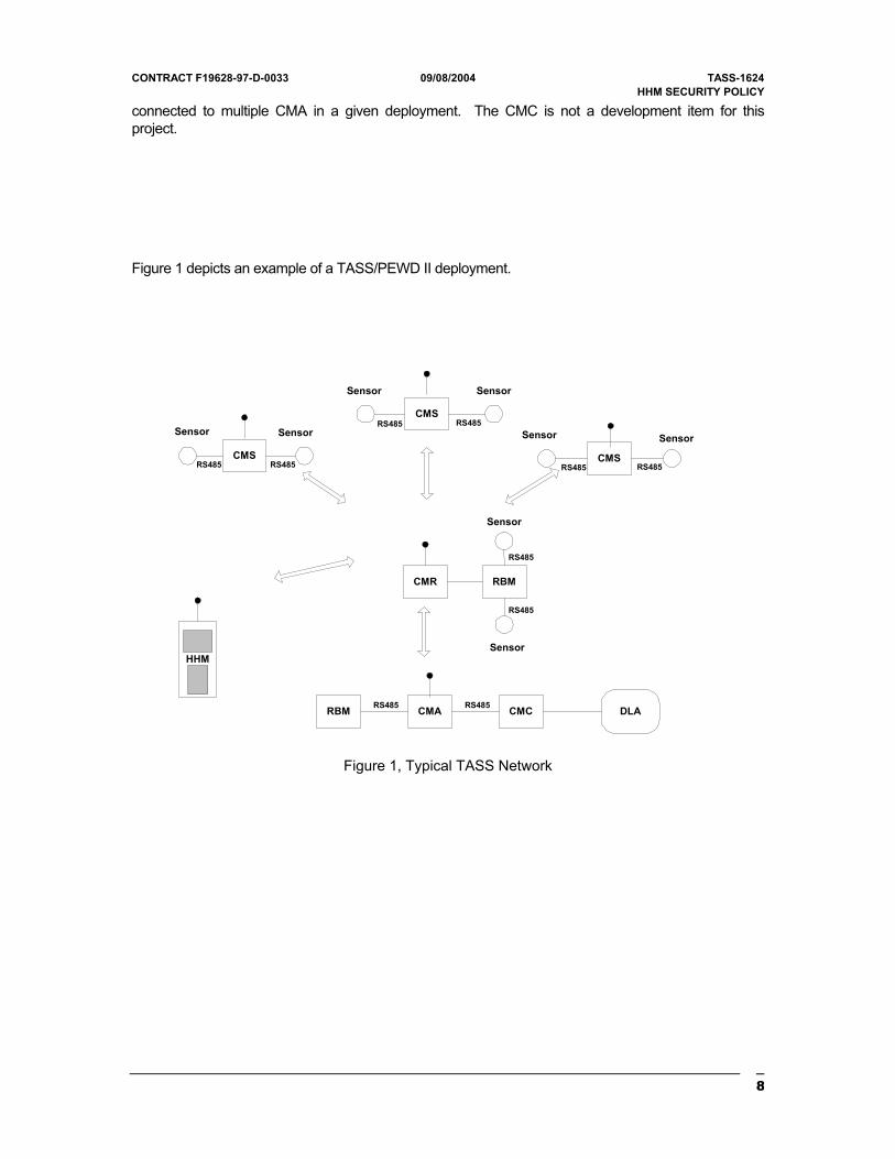
Figure 1 depicts an example of a TASS/PEWD II deployment.
CMS
CMS
CMS
CMR
CMA CMC DLA
RBM
RBM
HHM
SensorSensor
SensorSensor
SensorSensor
Sensor
Sensor
RS485 RS485
RS485
RS485
RS485RS485
RS485RS485
RS485RS485
Figure 1, Typical TASS Network
8
CONTRACT F19628-97-D-0033 09/08/2004 TASS-1624 HHM SECURITY POLICY
As mentioned above the HHM, along with the CM, incorporate commercial level cryptography. These components will be the only devices in the system with this capability. The algorithm used in these components is Triple DES.
Data encryption is applied to the following device functions:
• Encryption/decryption of data packets transferred over the RF port.
• Key variable distribution
• Message authentication for key exchange and firmware download operations.
• Internal key variable protection
Encryption and decryption of the content of the RF data packets is the primary application of cryptography for these devices. With the exception of key variables that are transferred over the RS485 ports all other data that is input and output from these devices is considered to be plain data. The CM and HHM can be configured for operation with encryption enabled or disabled.
9
CONTRACT F19628-97-D-0033 09/08/2004 TASS-1624 HHM SECURITY POLICY
1 Hand Held Monitor
Although there are many components of the TASS, this document services as the Security Policy for the Hand Held Monitor (HHM) and describes how the HHM meets FIPS 140-2 Level 1 Security Requirements.
1.1 Overall Functionality
The HHM is a master device with User interface designed to carry encrypted as well as plaintext communication. The functionality of HHM is to configure and coordinate activities with other CM/HHM devices in the TASS network. The details of HHM functionality are explained in subsequent paragraphs below.
The primary power input to the HHM is from a battery pack. The RS485 port is capable of providing an alternate power input (9 VDC – 15 VDC) from an external source.
The RF port sends and receives transmissions in the 132 to 176 MHz and 406 to 470 MHz bands. The modulation type utilized by the unit is narrow band FM and the transmit power output level is 1 watt minimum.
The single RS485 port can connect to the following devices:
• Communication Modules
• Other Hand Held Monitors
• Relocatable Battery Module
• Communications Module Converter (CMC)
When connected to a CM, the HHM can transfer the following types of data:
• CM configuration data (bi-directional)
• Key variable information (bi-directional)
• Upload firmware updates (both CPU and PLD)
10
CONTRACT F19628-97-D-0033 09/08/2004 TASS-1624 HHM SECURITY POLICY
When connected to another HHM the device can transfer the following types of data:
• Key variable information
• Upload firmware updates (both CPU and PLD)
• Current network time
The first two items are the same as for an HHM/CM data exchange operations. Network time is uploaded to the other HHMs to ensure that all devices in a network are synchronized. Network time is also transferred to CM, but is included in the CM configuration information.
When connected to an RBM the HHM is used to transfer configuration data to that unit.
When connected to a CMC, the HHM is indirectly interfacing to a DLA. This connection is used by the HHM to dump all CM configuration data for all CMs programmed by that device.
An internal Global Positioning System receiver in the HHM uses the GPS antenna.
The LCD display is used to display configuration menus and received messages
The firmware for the HHM and CM Controller is the same CSCI (and thus the same flash prom). On power-up the controller detects the presence or absence of a jumper on the board to determine whether it will function as a CM or HHM. As an HHM the Controller performs the following control functions:
• Radio control
1. Synthesizer control
2. Transmit/Receive control
3. Squelch
4. Base band data reception/transmission
• Power control
• RS485 port
1. RBM (SIC) protocol processing
2. CMC protocol processing
11
CONTRACT F19628-97-D-0033 09/08/2004 TASS-1624 HHM SECURITY POLICY
3. HHM protocol processing
• Incoming and Outgoing RF packet processing
• Real-Time-Clock
• Cryptographic operations
1. Cryptographic control
2. Triple DES encryption/decryption
3. Key management
4. Key generation
• User Interface for the following functions:
1. Entry of CM configuration settings and storage
2. Entry of the HHM’s settings
3. Key generation and entry of key variable parameters (key name and crypto period)
4. Key variable deletion (local and remote)
5. Display and manipulate a list of received alarm messages
An HHM has three major modes of operation:
• Annunicator mode.
• Configuration mode
• Locate mode
The device defaults to annunicator mode on power up. In this mode the HHM monitors the frequency for which it has been configured and notifies the operator via the display of any alarms received. The alarm event appears as a notification message in a single row of the display. Up to eight messages can be displayed on the device plus the operator can scroll through a list of the last sixteen events using the unit’s keypad. Icons are also displayed by the device to indicate when a message is being
12
CONTRACT F19628-97-D-0033 09/08/2004 TASS-1624 HHM SECURITY POLICY
received and to indicate if the device is operating with encryption enabled. An audio annunicator sounds a tone whenever a message is received.
Menu Configuration:
The HHM is set into configuration mode by pressing the menu key on the keypad. When this occurs a main configuration menu is displayed that provides the operator with eight possible choices:
• CM configuration
• RBM
• Contrast (display)
• Light (display backlighting)
• Volume (audio annunicator)
• Password
• HHM setup
• CM Locate
The CM configuration item provides access to all of the functions needed to configure one or more CMs for network operations. The operator can perform the following operations using HHM:
• Update a CMs CPU and/or PLD firmware to the HHM’s current version.
• Download a connected CM’s current configuration
• Set the CM’s unit ID
• Configure the CM as a CMA, CMR, or CMS
• Set the operating frequency of the CM
• Set the network routing parameters (group, repeater level, etc.) (CMS and CMR only).
13
CONTRACT F19628-97-D-0033 09/08/2004 TASS-1624 HHM SECURITY POLICY
• Enter the type of sensors to used (CMA, CMR only)
• Set the state-of-heath (SOH) reporting period
• Configure the SOH polling parameters (CMA only)
• Configure the receive message filter list (CMA and CMR only)
• Enable/disable encrypted mode operation
• Set the CM to accept or reject messages received with expired key variables (CMA only)
• Enable/disable low-power sleep mode operation (CMS only)
• Select co-ordinate entry configuration
• Enable reception of non-TASS messages (unencrypted mode only)
• Update firmware in attached device. The protocol used to transfer the data contains message authentication fields (TDES MAC codes) that are cryptography generated in accordance with the requirements of FIPS PUB 113.
Configuring the CM as a CMA, CMR, or CMS defines the behavior of the devices’ software.
The operating frequency can be set to within either of the two available ranges of 138 to 174 MHz or 406 to 470 MHz.
A CMA can be configured to periodically ping up to ten CM’s in the network for their state-of-health at a specified interval
If encryption is enabled by the HHM during configuration, the operator is given the option of either uploading the HHM’s current set of two Data Encryption Keys (DEKs) or using the current key set stored in the CM. The HHM menu displays the key names and expiration dates of the CM’s current key variables if the configuration download option was selected. If encryption is disabled, the HHM will automatically command the connected CM to purge any DEKs stored in the device.
Default key management policies for the TASS/PEWD II cryptography is for CMAs to accept messages encrypted using an expired DEK and send a warning message to operator that such an event occurred. If a message using an expired DEKs is received more than 24 hours after the expiration date, the receiving device automatically rejects the message. The configuration menu allows a setting that will prevent the rejection of such out-of-date encrypted messages.
14
CONTRACT F19628-97-D-0033 09/08/2004 TASS-1624 HHM SECURITY POLICY
Because CMs are typically hidden from sight when emplaced, they can be programmed with their geographic location when configured by the HHM. Each HHM contains a GPS receiver that is used to determine the current location the HHM/CM combination while the CM is being configured. At the end of the CM’s mission a HHM is used to query the unit via RF message to get its stored co-ordinates.
The TASS/PEWD II system is designed to inter-operate with other sensor platforms sharing the same RF link level protocols.
Once all of the configuration information has been entered, the HHM will upload the new configuration to the connected CM and also store the configuration to an internal database in the HHM’s flash memory. The database information is stored for later upload to a DLA.
HHM is used to configure RBM via the RS485 port. This information is then saved in the HHM internal database for later uploading to the DLA. No data configuration data is uploaded to the RBM directly.
The Password menu item allows the operator to perform the following functions:
• Change the HHM User password
• Change the HHM Crypto Officer password – Only if operator is a crypto officer
• Reset the all HHM passwords
• Reset the DLA password
The HHM User password is the five-digit password used to enter all configuration menus except those involving cryptographic functions.
The HHM Crypto Officer password is also a five-digit number used to place the unit into the Crypto Officer role. In this role, the Crypto Officer gains entry to the HHM functions that involve cryptographic operations.
The HHM setup menu allows the operator to configure the local device’s internal settings, the parameters for the system’s cryptographic operations, and configure other HHMs attached via RS485 port.
The HHM can upload the current contents of its CM configuration database to a DLA.
The purge CM configuration operation completely erases all records in the HHM’s configuration database for CMs. The HHM’s and cryptographic configuration records are unaffected by this operation.
15
CONTRACT F19628-97-D-0033 09/08/2004 TASS-1624 HHM SECURITY POLICY
Any operation involving encryption needs devices to be in encrypted mode, which is enabled by Crypto Officer. The authentication mechanism for crypto officer is explained under Section 5 and key Transfer mechanism while downloading or uploading keys are explained under Section 9.4.
The Upload key set operation allows the HHM to transfer its current DEKs key set information to another HHM attached via the RS485 port. The DEKs are encrypted during this transfer using the Key Encryption Key variable shared by all CM and HHM devices. Once the exchange is successfully completed the attached HHM replaces its current DEKs key set with the new key variable information.
The HHM can also download and replace its current DEKs key set with that of another device (HHM or CM) from an HHM setup menu prompt. The DEKs are encrypted during the transfer using the KEK as in the key set upload operation. The received DEKs are stored as the unit’s current key set, replacing the old.
The HHM setup menus provide a means for the local HHM to replace the CPU and PLD firmware of an attached HHM. This process is identical to that which is described for re-programming CMs.
The Enable/Disable SOH message display menu item determines whether SOH messages received from CMs in the network will be displayed on the LCD. The HHM will still internally monitor such messages and display an alarm message whenever a unit is overdue for a “check-in” regardless of this setting.
The enable/disable RF acknowledgement menu affects whether the HHM behaves as a monitor only or as the root node of the network. The HHM behaves as a monitor of RF messages only when this feature is disabled; the device is permitted to transmit following RF message types only:
• SOH
• Network time update requests
• Locate and Position commands
• RBM relay control commands
When the RF message acknowledge feature is enabled the HHM behaves as the root node of the deployed network, taking the place of a DLA/CMA combination that normally forms the root of a TASS network. Any commands involving encryption keys requires the device to be in encrypted mode and commands to be encrypted and authenticated. When this feature is enabled the HHM can perform these additional functions:
• Provide RF message acknowledgements
• Provide network time updates to out-of-sync nodes
16
CONTRACT F19628-97-D-0033 09/08/2004 TASS-1624 HHM SECURITY POLICY
• Send key changeover commands to switch the network nodes from primary to secondary DEKs (manual and automatic modes)
• Report DEKs expiration events on the display
• Report the reception of messages using an expired DEKs
An HHM is used to set the current time for any given network. The network time in any given deployment is defined as that kept in the real time clock of the CMA or HHM that is assigned as the root node of the network. In a CMA, the current time is set by the HHM that is used to configure that device. The current time for that HHM is derived either from the GPS satellite system via the internal GPS receiver, or from manual entry of the time and date by the operator.
The Locate mode of the HHM is used for CM recovery operations and to acquire, display and optionally transmit the current location of the HHM to the DLA. This function is only available in a TASS network where encryption has been enabled.
The HHM location mode, as stated, can also be used to acquire and display its current GPS co-ordinates. Once the current location is acquired the operator is given the option of transmitting those co-ordinates to the DLA only while operating in encryption mode.
The command network DEKs switchover function is available to the operator if the HHM RF message acknowledges feature is enabled, as mentioned above. This feature allows the operator to manually initiate a broadcast command sequence to all nodes in a network (CMs and HHMs) that will force the nodes to switch their operational DEKs over to the secondary DEKs, regardless of the primary’s expiration date. A HHM will also issue DEKs changeover commands automatically to individual nodes when a message is received that was encrypted with an expired primary DEKs.
The DEKs zeroization function permits an operator to zeroize the DEKs in the HHM. Submenus of the Zeroization process permit an authorized operator the ability to erase all keys (DEKs and internal) and all firmware in the local device or one attached to the RS485 port. Once this operation is performed, the targeted device will become completely inoperative. The erased unit must be returned to the manufacturer for reprogramming; it cannot be programmed in field in this state.
The HHM operator can select whether the HHM and all units configured by the unit will operate using one of the following cryptographic algorithms:
• Triple DES
• Encryption disabled
The selection of keys for Triple DES - Triple DES with three identical keys or Triple DES with 3 different keys, does not actually change the configuration of the algorithms; it selects how the DEKs are generated. The TASS/PEWD II HHM and CMs utilize the Triple DES algorithm as the core of its
17
CONTRACT F19628-97-D-0033 09/08/2004 TASS-1624 HHM SECURITY POLICY
PLD crypto engine. This Triple DES implementation utilizes three 56-bit sub keys. The operator has a choice to select TDES with three identical keys or TDES with 3 different keys. The use of TDES with 3 identical keys is equivalent to single DES and is only allowed for legacy systems. A change in the crypto algorithm type will force the operator to generate a new set of DEKs. Whenever encryption is disabled the unit will purge its current key sets. Any devices configured by this HHM will have their key sets purged also.
An operator can also elect to generate a new set of DEKs. The HHM will generate both a primary and secondary DEKs using the recommended key generation algorithm in ANSI X9.31, Appendix A.2.4.
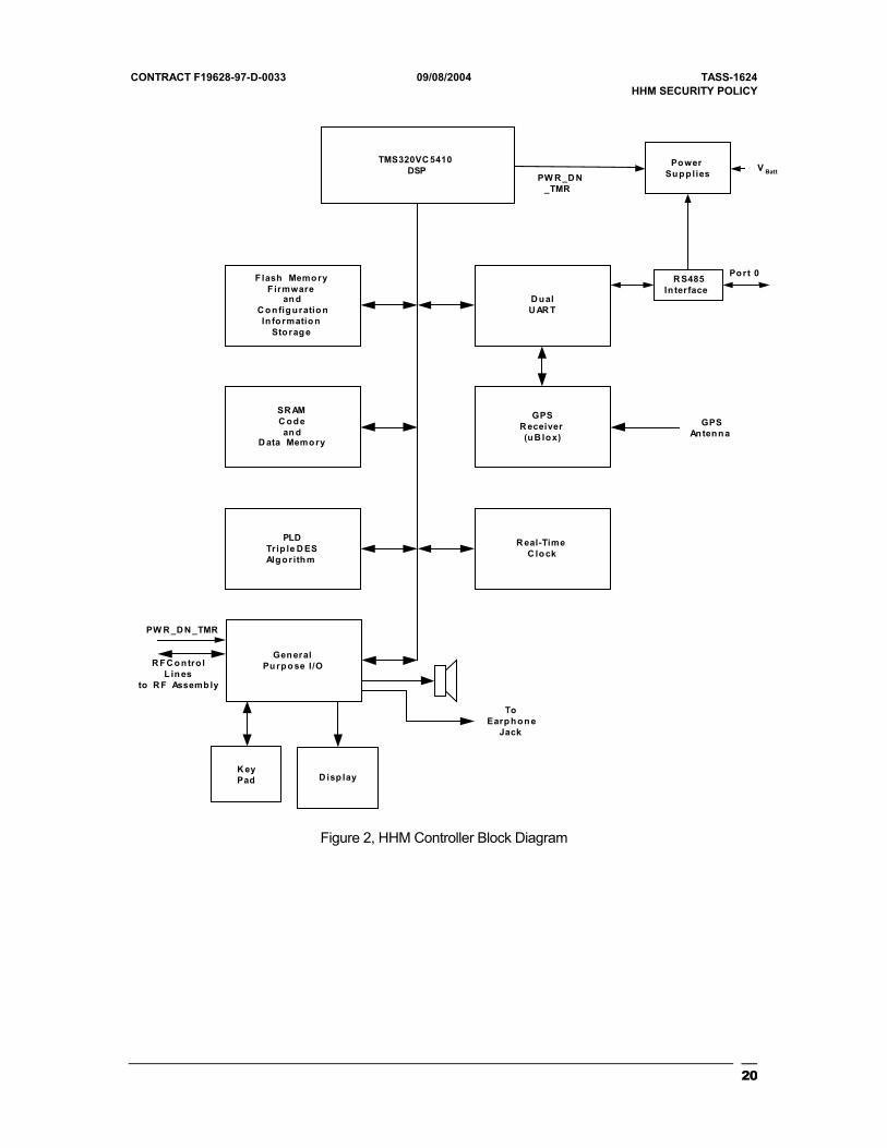
2 The Cryptographic Module Specifications
The TASS HHM falls under the “multi-chip standalone module” category of FIPS 140-2. The hardware design consists of two printed wiring boards (PWBs) contained within a metal case, which defines boundary of module. The PWBs are the Controller Assembly and the RF Assembly. The Controller Assembly performs all radio control and data processing functions for the device, including all cryptographic functions. The RF Assembly provides the RF physical layer functionality for the HHM. Since all cryptographic functions are performed in the comptroller assembly, the RF assembly is excluded from the requirements of FIPS 140-2.
Figure 2, shows a simplified block diagram of the Controller Assembly. The Controller Assembly performs all radio control and data processing functions for the device, including all cryptographic functions.
18

CONTRACT F19628-97-D-0033 09/08/2004 TASS-1624 HHM SECURITY POLICY
19
CONTRACT F19628-97-D-0033 09/08/2004 TASS-1624 HHM SECURITY POLICY
TMS320VC 5410DSP
SR AMC odean d
D ata Memory
F lash MemoryF irmware
an dC onfiguratio nIn formatio n
Storag e
PLDTrip le D ESAlgorithm
D ualU AR T
R eal-TimeC lock
GeneralPu rpo se I /O
R S485In terface
PowerSupplies
Port 0
V Batt
R F C o ntro lL in es
to R F Assemb ly
PW R _D N_TMR
PW R _D N _TMR
K eyPad D isp lay
GPSR eceiver(uB lox)
GPSAntenna
ToEarp hon e
Jack
Figure 2, HHM Controller Block Diagram
20
CONTRACT F19628-97-D-0033 09/08/2004 TASS-1624 HHM SECURITY POLICY
3 Cryptographic Module Security Policy
The cryptographic functions of the HHM employ the Triple DES algorithm. All cryptographic operations of the device use Triple DES with 3 identical keys or with 3 unique keys. Security functions performed by the HHM cryptography are:
• RF message encryption/decryption: TDES, FIPS PUB 46-3 compliant
• RF message bypass (unencrypted mode operation)
• Message and data authentication, FIPS PUB 113 compliant
• Pseudo-random number generation. ANSI X9.31 Appendix A.2.4
• Key variable generation, ANSI X9.31 Appendix A.2.4
• Data Encryption Keys (DEKs) exchange: FIPS 171 compliant
• Key management functions, DEKs storage, DEKs erasure, DEKs masking, crypto period enforcement
The cryptographic functions in the HHM use a combination of hardware and software. The Triple DES algorithm is a hardware implementation, residing in a Programmable Logic Device (PLD Logic has been added to the PLD design to implement FIPS approved CBC as well as ECB modes operation.
Cryptographic control and Key Management for the module is implemented in software. Access to all cryptographic and RTOS services by the non-critical tasks is limited to a well-defined set of API functions.
Enforcement of the crypto boundary is implemented using logical separation in the software that controls the device. The platform for the HHM software is a Texas Instruments TMS320C5410 Digital Signal Processor (DSP). The DSP is a modified Harvard design that utilizes separate buses for data and code memory. For the HHM the application software runs entirely out of static RAM (SRAM), both internal and external to the DSP. This software is loaded into SRAM during the cold boot process from flash memory. The HHM software utilizes a real-time-operating system RTOS, running in a non pre-emptive mode that allows the software to execute as a number of discrete concurrent tasks. Each task is designed to operate in only one of three logical partitions of the system bypass region, plain text region and critical memory region. Tasks in the bypass partition handle plain text message data with one notable exception. Key exchange messages containing encrypted DEKs are handled by bypass
21
CONTRACT F19628-97-D-0033 09/08/2004 TASS-1624 HHM SECURITY POLICY
tasks. Please note, however, that bypass tasks only handle encrypted key variables during DEKs transfer processes.
Tasks in the plain partition handle cipher text message data only. The exception to this rule is when the HHM is configured for unencrypted operation. The case of unencrypted operation the flow of plain text data through these tasks are governed by the rules for cryptographic bypass operations.
The third partition is the Critical partition. Tasks running in this partition form the bypass/plain boundary of the system and perform all cryptographic and security related services for the system and are the enforcers of the system security policies.
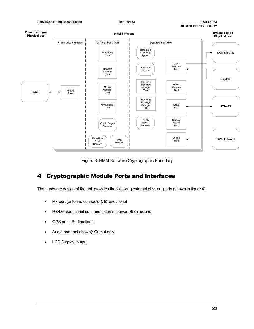
Figure 3 shows the relationship between the HHM software components and the cryptographic boundary. The diagram shows all of the tasks in the application along with the major service components. The relationship between the data carrying physical ports and the task that serve them is also shown. The power interface is excluded since it does not carry information.
22
CONTRACT F19628-97-D-0033 09/08/2004 TASS-1624 HHM SECURITY POLICY
Radio
LCD Display
KeyPad
RS-485
GPS Antenna
CryptoManager
Task
Key ManagerTask
RandomNumber
Task
IncomingMessageManager
Task
UserInterface
Task
SerialTask
AlarmManager
Task
State ofHealthTask
RF LinkTask
LocateTask
WatchdogTask
Plain text Partition Critical Partition Bypass Partition
Run TimeLibrary
Real-TimeOperatingSystem
TimerServices
OutgoingMessageManager
Task
Bypass regionPhysical port
Plain text regionPhysical port HHM Software
Crypto EngineServices
PLD &GPIO
Services
Real-TimeClock
Services
Figure 3, HMM Software Cryptographic Boundary
4 Cryptographic Module Ports and Interfaces
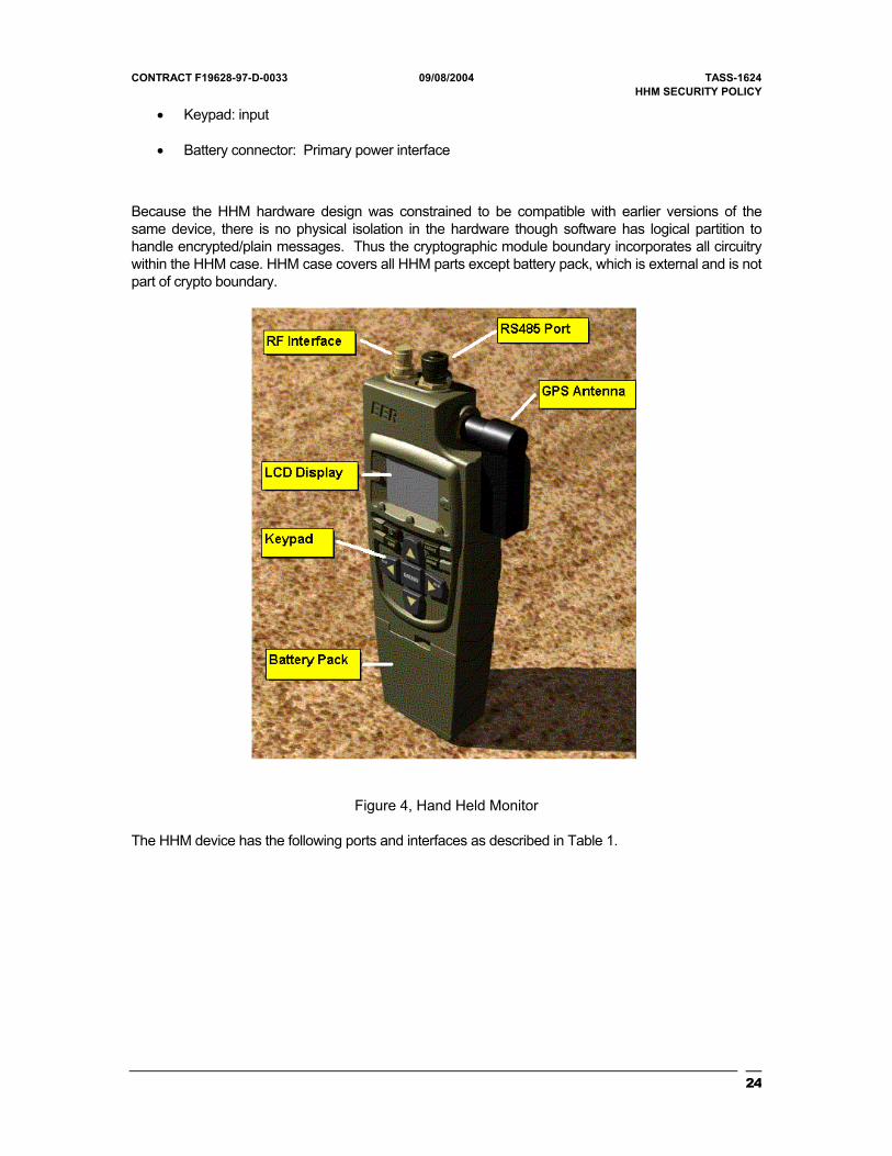
The hardware design of the unit provides the following external physical ports (shown in figure 4)
• RF port (antenna connector): Bi-directional
• RS485 port: serial data and external power. Bi-directional
• GPS port: Bi-directional
• Audio port (not shown): Output only
• LCD Display: output
23
CONTRACT F19628-97-D-0033 09/08/2004 TASS-1624 HHM SECURITY POLICY
• Keypad: input
• Battery connector: Primary power interface
Because the HHM hardware design was constrained to be compatible with earlier versions of the same device, there is no physical isolation in the hardware though software has logical partition to handle encrypted/plain messages. Thus the cryptographic module boundary incorporates all circuitry within the HHM case. HHM case covers all HHM parts except battery pack, which is external and is not part of crypto boundary.
Figure 4, Hand Held Monitor
The HHM device has the following ports and interfaces as described in Table 1.
24
CONTRACT F19628-97-D-0033 09/08/2004 TASS-1624 HHM SECURITY POLICY
Table 1, HHM Ports and Interfaces
Physical Ports Logical Interfaces
Battery Pack Power Input
RS485 port Data Input, Data Output, Control Input, Status Output
GPS antenna port Data Input, Data Output, Control Input, Status Output
RF antenna port Data Input, Data Output, Control Input, Status Output
Keypad Data input, control input
LCD Display Data output, Status output
Audio port – earphone jack & speaker Status output
• Battery Pack: This is power interface. Power (9 VDC – 15 VDC) is input to the device either through a battery pack through the power connector, or via one of the RS485 connectors.
• RS485 Port: Each of the RS485 ports can connect to the following:
CM – To configure CM, upload/download firmware, upload/download encryption keys, Erase keys/firmware in CM. PC – Connect to PC for downloading firmware using PC download program. HHM – To upload/download firmware, upload/download encryption keys, erase keys/firmware in HHM. RBM – To configure RBM.
• GPS Port: The GPS antenna is provided on HHM. The GPS information can be obtained by pressing gps button HHM. The location information is used for device recovery, network synchronization and self-location reports.
• RF Port: The antenna connector for the UHF/VHF transceiver portion of the HHM. RF data packets for the network are input/output through this port.
• Keypad: The operator input is through HHM keypad. Operator access all menus/ options and keys through this interface. Refer to section 1.1, “Overall Functionality” for menu details.
• LCD Display: This interface provides status display for all communication. Displays all types of alarms like sensor, State of health, spoof or any fault functioning. Also displays status
25
CONTRACT F19628-97-D-0033 09/08/2004 TASS-1624 HHM SECURITY POLICY
messages while configuring, upload/download operations. Displays warnings under circumstances like attempting key erase, overwriting configurations, replacing keys.
• Audio Port: This interface communicates with Audio port to provide audio for alarms.
5 Roles and Services
The HHM implements two User roles and a Crypto-Officer role of operation. The roles are defined per the FIPS140-2 standard as follows:
1. Users - first level of access. Can’t modify encryption settings. Can configure CM devices and carry out services based on preset encryption capabilities. The User 1 is an operator who needs to authenticate with a User password to access User services offered by HHM. The User 2 is a CM or another HHM device that has access to the HHM through authenticated messages to access HHM services.
2. Crypto-Officer – second level access. Can access/carry all services implemented in the
Module, generate keys, download/upload encryption keys, firmware to/from other HHM/CM’s, erase local/remote keys, erase local/remote firmware. The crypto officer needs to authenticate with encryption password to access crypto services offered by HHM.
The HHM does not support a Maintenance role.
The HHM satisfies level 1 requirement for Roles, Services, and Authentication, which do not require authentication of operators. However the HHM is designed to require authentication to perform User services as well as crypto services.
5.1 User Role commands:
Following are User commands issued by HHM:
Table 2, HHM User Role Commands
Command Description
Send RF Message Sends a message packet over the RF network in response to an alarm or control event.
Receive RF Message Receive and process a message from the RF network.
26
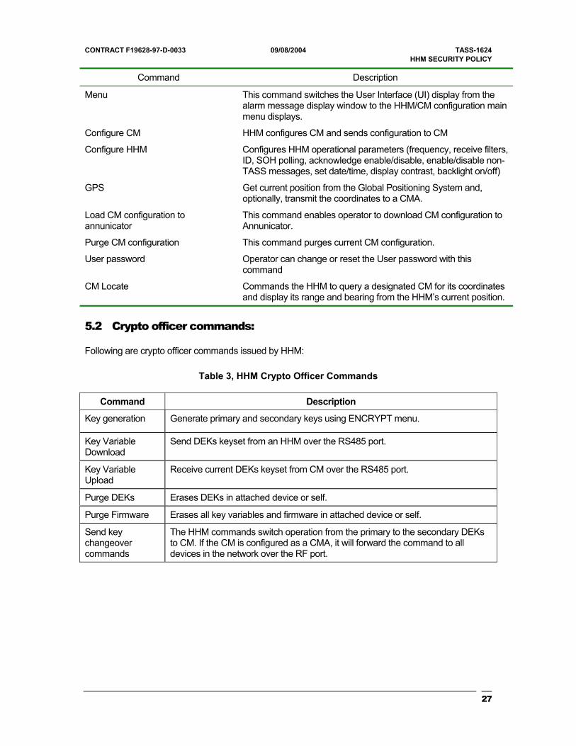
CONTRACT F19628-97-D-0033 09/08/2004 TASS-1624 HHM SECURITY POLICY
Command Description
Menu This command switches the User Interface (UI) display from the alarm message display window to the HHM/CM configuration main menu displays.
Configure CM HHM configures CM and sends configuration to CM
Configure HHM Configures HHM operational parameters (frequency, receive filters, ID, SOH polling, acknowledge enable/disable, enable/disable non-TASS messages, set date/time, display contrast, backlight on/off)
GPS Get current position from the Global Positioning System and, optionally, transmit the coordinates to a CMA.
Load CM configuration to annunicator
This command enables operator to download CM configuration to Annunicator.
Purge CM configuration This command purges current CM configuration.
User password Operator can change or reset the User password with this command
CM Locate Commands the HHM to query a designated CM for its coordinates and display its range and bearing from the HHM’s current position.
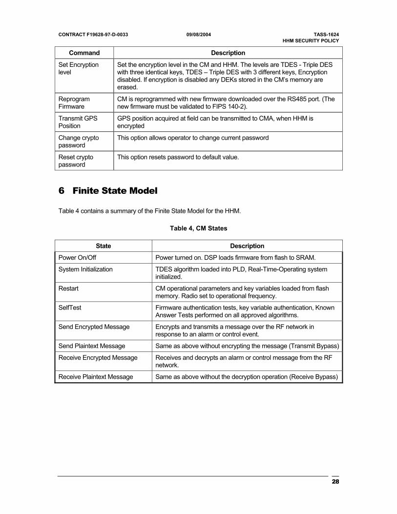
5.2 Crypto officer commands:
Following are crypto officer commands issued by HHM:
Table 3, HHM Crypto Officer Commands
Command Description
Key generation Generate primary and secondary keys using ENCRYPT menu.
Key Variable Download
Send DEKs keyset from an HHM over the RS485 port.
Key Variable Upload
Receive current DEKs keyset from CM over the RS485 port.
Purge DEKs Erases DEKs in attached device or self.
Purge Firmware Erases all key variables and firmware in attached device or self.
Send key changeover commands
The HHM commands switch operation from the primary to the secondary DEKs to CM. If the CM is configured as a CMA, it will forward the command to all devices in the network over the RF port.
27
CONTRACT F19628-97-D-0033 09/08/2004 TASS-1624 HHM SECURITY POLICY
Command Description
Set Encryption level
Set the encryption level in the CM and HHM. The levels are TDES - Triple DES with three identical keys, TDES – Triple DES with 3 different keys, Encryption disabled. If encryption is disabled any DEKs stored in the CM’s memory are erased.
Reprogram Firmware
CM is reprogrammed with new firmware downloaded over the RS485 port. (The new firmware must be validated to FIPS 140-2).
Transmit GPS Position
GPS position acquired at field can be transmitted to CMA, when HHM is encrypted
Change crypto password
This option allows operator to change current password
Reset crypto password
This option resets password to default value.
6 Finite State Model
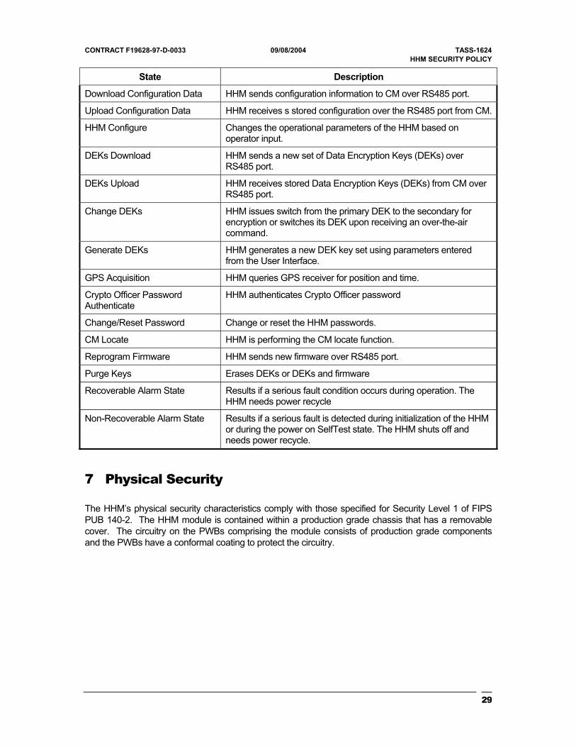
Table 4 contains a summary of the Finite State Model for the HHM.
Table 4, CM States
State Description
Power On/Off Power turned on. DSP loads firmware from flash to SRAM.
System Initialization TDES algorithm loaded into PLD, Real-Time-Operating system initialized.
Restart CM operational parameters and key variables loaded from flash memory. Radio set to operational frequency.
SelfTest Firmware authentication tests, key variable authentication, Known Answer Tests performed on all approved algorithms.
Send Encrypted Message Encrypts and transmits a message over the RF network in response to an alarm or control event.
Send Plaintext Message Same as above without encrypting the message (Transmit Bypass)
Receive Encrypted Message Receives and decrypts an alarm or control message from the RF network.
Receive Plaintext Message Same as above without the decryption operation (Receive Bypass)
28
CONTRACT F19628-97-D-0033 09/08/2004 TASS-1624 HHM SECURITY POLICY
State Description
Download Configuration Data HHM sends configuration information to CM over RS485 port.
Upload Configuration Data HHM receives s stored configuration over the RS485 port from CM.
HHM Configure Changes the operational parameters of the HHM based on operator input.
DEKs Download HHM sends a new set of Data Encryption Keys (DEKs) over RS485 port.
DEKs Upload HHM receives stored Data Encryption Keys (DEKs) from CM over RS485 port.
Change DEKs HHM issues switch from the primary DEK to the secondary for encryption or switches its DEK upon receiving an over-the-air command.
Generate DEKs HHM generates a new DEK key set using parameters entered from the User Interface.
GPS Acquisition HHM queries GPS receiver for position and time.
Crypto Officer Password Authenticate
HHM authenticates Crypto Officer password
Change/Reset Password Change or reset the HHM passwords.
CM Locate HHM is performing the CM locate function.
Reprogram Firmware HHM sends new firmware over RS485 port.
Purge Keys Erases DEKs or DEKs and firmware
Recoverable Alarm State Results if a serious fault condition occurs during operation. The HHM needs power recycle
Non-Recoverable Alarm State Results if a serious fault is detected during initialization of the HHM or during the power on SelfTest state. The HHM shuts off and needs power recycle.
7 Physical Security
The HHM’s physical security characteristics comply with those specified for Security Level 1 of FIPS PUB 140-2. The HHM module is contained within a production grade chassis that has a removable cover. The circuitry on the PWBs comprising the module consists of production grade components and the PWBs have a conformal coating to protect the circuitry.
29
CONTRACT F19628-97-D-0033 09/08/2004 TASS-1624 HHM SECURITY POLICY
8 Operational Environment
Cryptographic control and Key Management for the module is implemented in firmware. This firmware is written in the C language, with some minor time critical exceptions written in the host platform’s assembly language. The application runs on a real-time operating system (RTOS). The RTOS runs in a non pre-emptive mode thus ensuring that each task relinquishes its control of the system only at pre-defined points of its execution. All firmware that performs secure functions is logically isolated from non-cryptographic code in separate object code modules. These modules execute in system tasks separate from those in which the non-secure code executes. Access to all cryptographic and RTOS services by the non-critical tasks are limited to a well-defined set of API functions used during the development.
The HHM firmware provides an application specific operational environment, responding only to the command set that was developed for it. As manufactured the HHM firmware, in flash memory, is pre-programmed into memory at the factory. The HHM firmware is capable of being updated with new firmware using either a PC download program, or by an HHM with the new version of the code via serial transfer through one of it RS485 ports. Only firmware validated to FIPS 140-2 that is authenticated by a Triple DES MAC value can be loaded into the module.
9 Cryptographic Key Management
The cryptographic functions of the HHM employ the Triple DES algorithm. Implementation of this algorithm is either Triple DES using a key variable consisting of three identical sub-keys or Triple DES using 3 unique keys depending on operator selection. Security functions performed by the HHM cryptography are:
• RF message encryption/decryption: TDES, FIPS PUB 46-3 compliant
• RF message bypass (unencrypted mode operation)
• Message and data authentication, FIPS PUB 113 compliant
• Pseudo-random number generation. ANSI X9.31 Appendix A.2.4.
• Key variable generation, ANSI X9.31 Appendix A.2.4
• Data Encryption Keys (DEKs) exchange: FIPS 171 compliant
30
CONTRACT F19628-97-D-0033 09/08/2004 TASS-1624 HHM SECURITY POLICY
• Key management functions, DEKs storage, DEKs erasure, DEKs masking, crypto period enforcement
The cryptographic functions in the HHM use a combination of hardware and software. The Triple DES algorithm is a hardware implementation, which implements FIPS approved CBC as well as ECB modes of operation.
9.1 Key Management
The Module implements a number of functions that are either used internally or exposed in the API to meet the FIPS140-2 Level 1 requirement for Key Management.
Key Management in the HHM software incorporates to two types of key variables. These key variables types are:
• Data Encryption Keys (DEKs)
• Internal key variables
DEKs are TDES variables used in the encryption and decryption of message data passed over the TASS RF network. The DEKs can be generated by the HHM and transferred (in encrypted form) between HHMs and CMs over the RS485 serial ports. Each DEK has a crypto period and key name associated with it.
The internal key variables are fixed variables used by the system with no crypto period. They are not generated by the HHM and can only be changed by downloading the firmware with new sets of keys to the HHM, which requires devices to be turned back to factory. The internal variables are:
• Key Generating Key (KGK): A Triple DES variable used in the ANSI X9.31 approved pseudo-random number generator algorithm.
• Key Encryption Key (KEK): This is the Triple DES key variable used to encrypt DEKs variables during key transfers.
• Default Authentication Key (KA): This is the Triple DES key variable used for the FIPS 113 approved authentication algorithm for message and data authentication (except DEKs transfers).
• Session Authentication Key (SessionKA): This is the authentication key used to authenticate all DEKs transferred over the RS485 port. It is the transferred DEKs itself.
31
CONTRACT F19628-97-D-0033 09/08/2004 TASS-1624 HHM SECURITY POLICY
• Fixed Masking Key: This is one component of the TDES masking key used to protect the internal key variables in memory. It is combined with the Split Key to form a Triple DES masking key.
• Split Key: This is the second component of the TDES masking key used by all key variables in the HHM. It is combined with the Fixed Masking Key to form the TDES masking key used to protect the internal key variables. It is combined with a DEKs key name to form its masking key.
• Triple DES masking Key: The key formed by XORing two components of the Fixed Masking Key and the Split Key. The Triple DES masking Key is used to encrypt keys stored in HHM memory.
• Electronic Codebook KAT Key (ECBKAT): This is the Triple DES key used for the Electronic Codebook mode Known Answer Test.
• Cipher Block Chaining KAT Key (CBCKAT): This is the Triple DES key used for the Cipher Block Chaining mode Known Answer Test.
• Random Number Generator KAT Key (RNGKAT): This is the Triple DES key used for the RNG KAT.
9.2 Pseudo Random Number Generation
The HHM Pseudo Random Number generator utilizes the approved algorithm recommended in ANSI x9.31 1998, Appendix A.2.4.
This algorithm is performed by the Random Number (PRN) task in the HHM. This task generates blocks of up to 128 random numbers in advance of their need and places them in a random number queue. Once the queue is filled the PRN task suspends itself until the queue falls below a threshold of 64 numbers, at which time the task is reactivated until the queue is filled once more. Each R vector generated is continuously compared to the previous R vector generated. If two consecutive R vectors are equivalent, the PRN task will force the HHM into a crypto alarm state.
The HHM firmware obtains the 16-bit random numbers using the Crypto API service CM_RandomNumber. Each call to CM_RandomNumber returns a single random number from the queue. In order to guard against corruption of the queue, CM_RandomNumber also performs a continuous random number check on the prns accessed.
32
CONTRACT F19628-97-D-0033 09/08/2004 TASS-1624 HHM SECURITY POLICY
9.3 Key Generation
The HHM has the ability to generate Triple DES DEKs from the User Interface. Keys for TDES are generated by creating 64-bit sub keys. TDES will have either three sets of unique 64-bit sub keys or three identical sub key values of 64-bits for single DES operation. The PRNG implemented for key generation follows the recommendations ANSI x9.31, Appendix A.2.4.
The HHM will generate both a primary and secondary DEKs using the PRNG.
The key name constitutes 16 bytes. Out of which 7 bytes are entered by the operator through HHM keypad. It is alphanumeric. The 8th digit is added by software to identify primary and secondary keys. The next 8 bytes of key name are internally generated by software.
The operator is prompted to enter an expiration date for each (if the default crypto period is not desired).
After the Key Manager software generates each sub-key, it is compared to a list of known weak keys. If the generated sub-key matches any of the keys in the list it is discarded and a new sub-key is generated to replace it. If four consecutive attempts to generate a good sub-key fails the Key manager will place the HHM in a crypto alarm state.
The generated key variables and their associated parameters are masked and stored in the KeyList and in flash memory immediately after creation. All plain text copies of the keys are purged. The generated key variables are never transferred outside the Key Manager task during the key generation process. Only a DEKs expiration date and key name are viewable by the operator.
All HHM I/O is disabled during the key generation process and no intermediate key generation values are ever output from the module.
9.4 Key Establishment
The HHM serves as a key loader device for the TASS system. As such it has the ability to:
• Download DEKs to CMs or other HHMs
• Upload DEKs from CMs or HHMs
These transfers are performed over the RS485 port only. The HHM encrypts DEKs before key establishment. This protocol is FIPS 171 compliant and includes the following command messages:
33
CONTRACT F19628-97-D-0033 09/08/2004 TASS-1624 HHM SECURITY POLICY
• Request for Service Initiation (RSI): Initiates all DEKs transfer processes.
• Data Key_Key Service Message (KD_KSM): Message that contains a single DEKs variable, its expiration date, key name. The DEKs is encrypted using the KEK.
• Response Service Message (RSM): Acknowledges successful reception of a message.
• Error Service Message (ESM): Sent when a fault occurs in the processing of a message.
• Key Name Query (KNQ): Requests the key name and expiration date of a DEKs.
• Key Name Response (KNR): The response to a KNQ message. Contains the key name and expiration date of the requested key. This information is plain text.
The KD_KSM, RSI, ESM, and RSM messages include 32-bit Message Authentication Codes, generated using the FIPS 113 approved algorithm. The RSM, RSI, and ESM messages use the default authentication key (KA) for this process. The KD_KSM message uses the transferred DEK as the authentication key.
The Disconnect Service Message (DSM) is used to command a device connected to the HHM to erase its DEKs or all keys and firmware. This message includes a Triple DES MAC that is generated using the default authentication key.
9.5 Key Entry & Output
The internal key variables are installed as a part of the firmware, in flash memory, during the manufacturing process. The internal keys are produced during the development effort and are included in an object module linked with the rest of the firmware during the code build process. The object module containing the internal keys is compiled in a separate firmware project from the rest of the TASS code. This is done to separate the internal key variable source code from the rest of the firmware documentation. The key variables in source code are entered manually into the file. The keys are generated using the same FIPS approved algorithm (ANSI X9.31, Appendix A.2.4) as used to generate DEKs in the HHM and are encrypted using the masking technique described in paragraph 9.6.2. The encrypted key variables are then entered into the source file and compiled to generate the object module. The internal keys are masked in the object module to protect them from being compromised by an analysis of the contents of flash memory or during firmware download operations.
34
CONTRACT F19628-97-D-0033 09/08/2004 TASS-1624 HHM SECURITY POLICY
9.6 Key Storage
9.6.1 Key Variable Storage
The primary storage object for the key variable during operation of the HHM is the KeyList, which resides in SRAM in the firmware’s data memory area (address range 0x8000 to 0xFFFF). This object holds a record for each key variable used by the device. These records vary in size and structure, dependent upon the type of key variable stored in the record.
The key record for DEKs contains the following information:
• The masked key variable
• The DEKs key name
• The DEKs expiration date
• The DEKs current state (standby, active, stale, purged)
Standby – The state of a secondary key when the primary key is in use as the secondary is the standby key.
Active – The current valid key, which is being used.
Stale – The expired primary or secondary key still being used, which has a 24-hour grace period.
Purged – Key doesn’t exist anymore as it has been deleted.
Expired – Keys are expired, crossed 24 hour grace period, can’t be used anymore.
The key record for internal keys consists of the masked key variable only.
Because the HHM does not employ any battery backup for its memory, the masked key variables and their current state (DEKs only) are also stored in flash memory in a structure named TRadioParameters. This structure resides in a separate sector of flash memory from the firmware and device configuration information (address 0x40A000 to 0x40AFFF). All key variables are loaded from flash memory to the KeyList whenever the HHM is (re) booted. The records stored in flash also contain the authentication code for each key record to ensure the validity of the key load process. Whenever a DEKs changes state, DEKs are transferred, or new firmware is downloaded into the
35
CONTRACT F19628-97-D-0033 09/08/2004 TASS-1624 HHM SECURITY POLICY
HHM, the key variables in flash are updated as well as the KeyList in SRAM. The firmware uses the key variables from the KeyList in SRAM for its cryptographic operations because the access time for memory in SRAM is faster than that in flash memory. Thus the key variables in flash are only accessed during boot operations of the firmware and store any changes to the keys or their state in non-volatile memory.
9.6.2 Protection of Keys
The keys are stored in flash and in SRAM (in the KeyList) are protected from analysis and inadvertent corruption by several mechanisms.
Protection from analysis is achieved through the masking of the key variables. The masking processing utilizes Triple DES encryption of each key variable in memory using a specific masking key variable. Key variables are only unmasked immediately prior to each encryption/decryption operation and all unmasked copies of the key variable are purged immediately thereafter. The key variable used for masking is created only on demand, automatically, by the HHM from split components prior to the usage of any key variable and is destroyed immediately after each masking/unmasking operation. The two components are combined with an exclusive OR operation to form the masking key variable. It is realized that this is considered to be a weak protection mechanism, since all components of the masking key can be found in data memory. However, the mechanism employed requires a significant reverse engineering effort to defeat. This is considered to be beyond the semi-skilled threat level assessed by the primary customer for this system (USAF Electronic Systems Command). A different masking key combination is used for the DEKs (dependent on the unique key name of a DEKs) than is used for the internal key variables.
The discretionary and automatic key purge functions discussed in the previous paragraph offer a means of key protection that can be employed in the case of an overt security threat.
The HHM is protected from the inadvertent use of corrupted key variables through the use of 32-bit Data Authentication Codes stored with each key variable’s record in memory. Each Triple DES DAC is generated using the FIPS 113 approved algorithm. These DACs are used to check key variable validity under the following conditions:
• During cryptographic self-test
• When loading the KeyList from flash memory
• When storing key variables or DEKs state changes to flash memory
• Prior to performing any key transfer process.
• Whenever switching from primary to secondary DEKs, either manually or automatically.
36
CONTRACT F19628-97-D-0033 09/08/2004 TASS-1624 HHM SECURITY POLICY
If a corrupted key record is detected the HHM can attempt to recover the key from a backup copy which is also encrypted in same way as original key, also stored in flash memory. If the backup copy validates it will be used by the system, otherwise the keys are marked as purged and the HHM defaults to unencrypted mode. The operator is informed of this by removal of the encryption mode icon from the LCD display.
9.3 DEKs Crypto periods and DEK Switching:
The DEKs have crypto periods assigned to them, selectable by the operator at the time of their creation. The available crypto periods are:
• Manual
• 30 days
• 90 days
• 180 days
• No expiration
When the primary’s expiration date arrives, the HHM will automatically switch to the secondary DEKs and notify the operator of the event on the LCD display. The HHM will continue to accept and decrypt messages received encrypted in the primary DEKs from other units in the RF network over a 24-hour grace period following expiration. Whenever a message is received by an HHM using ”stale” DEKs the HHM will notify the operator of the event on the LCD display once for each unit ID. If the HHM is in its tactical mode (network root node), it will also send a Command Key Changeover message over the RF link to the offending unit to force it to change to the Secondary DEKs. After the 24-hour grace period the HHM will no longer accept messages encrypted in the expired DEKs, but will continue to send Command Key Changeover messages.
When the expiration date of the secondary DEKs occurs this key remains operational, however, the operator is notified of the expiration event via the LCD display. This notification will repeat at four-hour intervals until the HHM generates or receives a new set of DEKs.
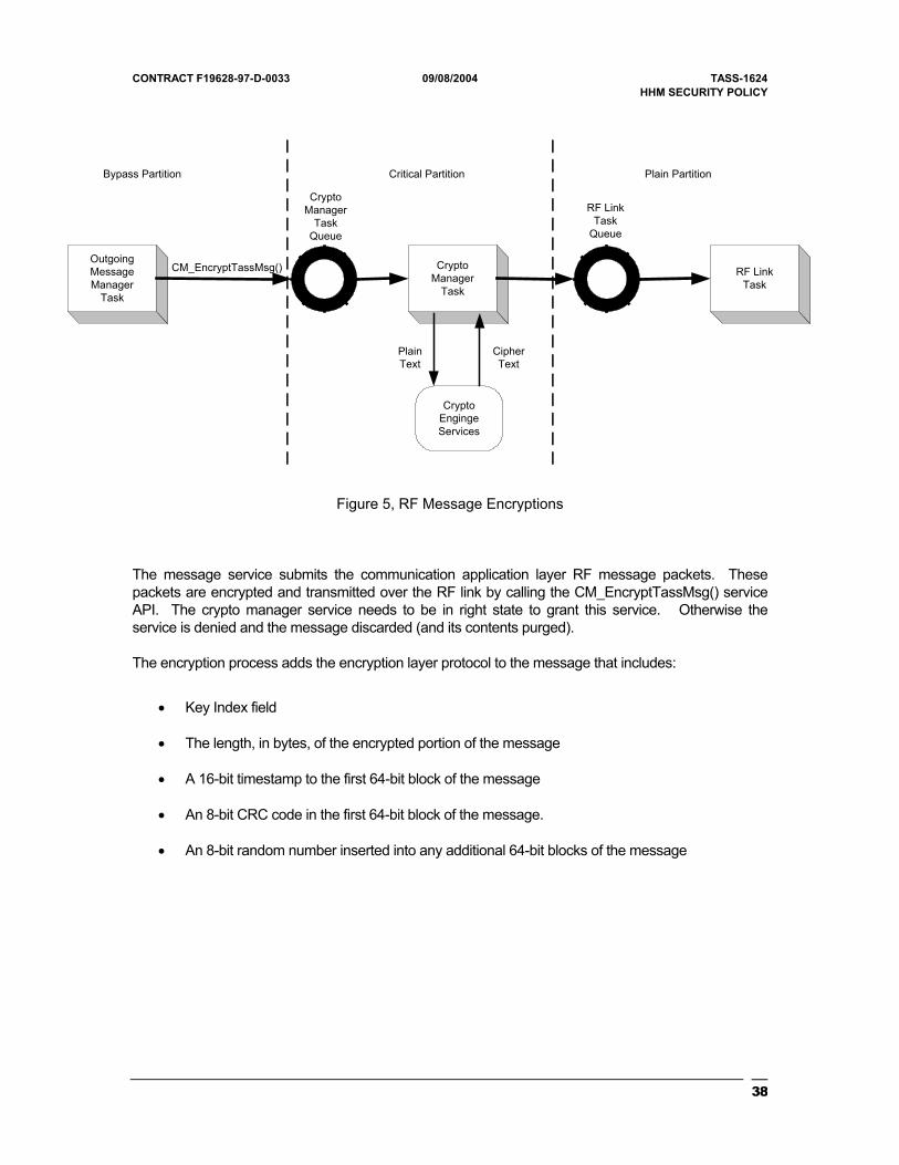
9.4 RF Message Encryption/Decryption
The primary role for cryptography in the HHM software is the encryption and decryption of messages transferred over the RF network. Figure 5 is simplified block diagram of the RF message encryption process.
37
CONTRACT F19628-97-D-0033 09/08/2004 TASS-1624 HHM SECURITY POLICY
OutgoingMessageManager
Task
CryptoManager
Task
RF LinkTask
CryptoEngingeServices
PlainText
CipherText
CryptoManager
TaskQueue
RF LinkTask
Queue
CM_EncryptTassMsg()
Bypass Partition Critical Partition Plain Partition
Figure 5, RF Message Encryptions
The message service submits the communication application layer RF message packets. These packets are encrypted and transmitted over the RF link by calling the CM_EncryptTassMsg() service API. The crypto manager service needs to be in right state to grant this service. Otherwise the service is denied and the message discarded (and its contents purged).
The encryption process adds the encryption layer protocol to the message that includes:
• Key Index field
• The length, in bytes, of the encrypted portion of the message
• A 16-bit timestamp to the first 64-bit block of the message
• An 8-bit CRC code in the first 64-bit block of the message.
• An 8-bit random number inserted into any additional 64-bit blocks of the message
38
CONTRACT F19628-97-D-0033 09/08/2004 TASS-1624 HHM SECURITY POLICY
The 16-bit timestamp serves two purposes. First, it is part of an anti-spoofing mechanism built into the system. Secondly it provides a changing data field in the message that is used to mitigate an encryption-in-depth threat posed by the use of ECB mode encryption for these messages. The resolution of the 16-bit timestamp is 125 milliseconds, which is greater than the smallest message transmission interval, thus preventing an identical cipher text for identical plain text message condition.
Once the cryptographic protocol has been added to the message, it is encrypted using the Crypto Engine API, CE_EncryptData. The resultant cipher text is placed in the RF Link task’s queue for transmission. The original plain text message buffer is de-allocated and its contents purged at the conclusion of this process.
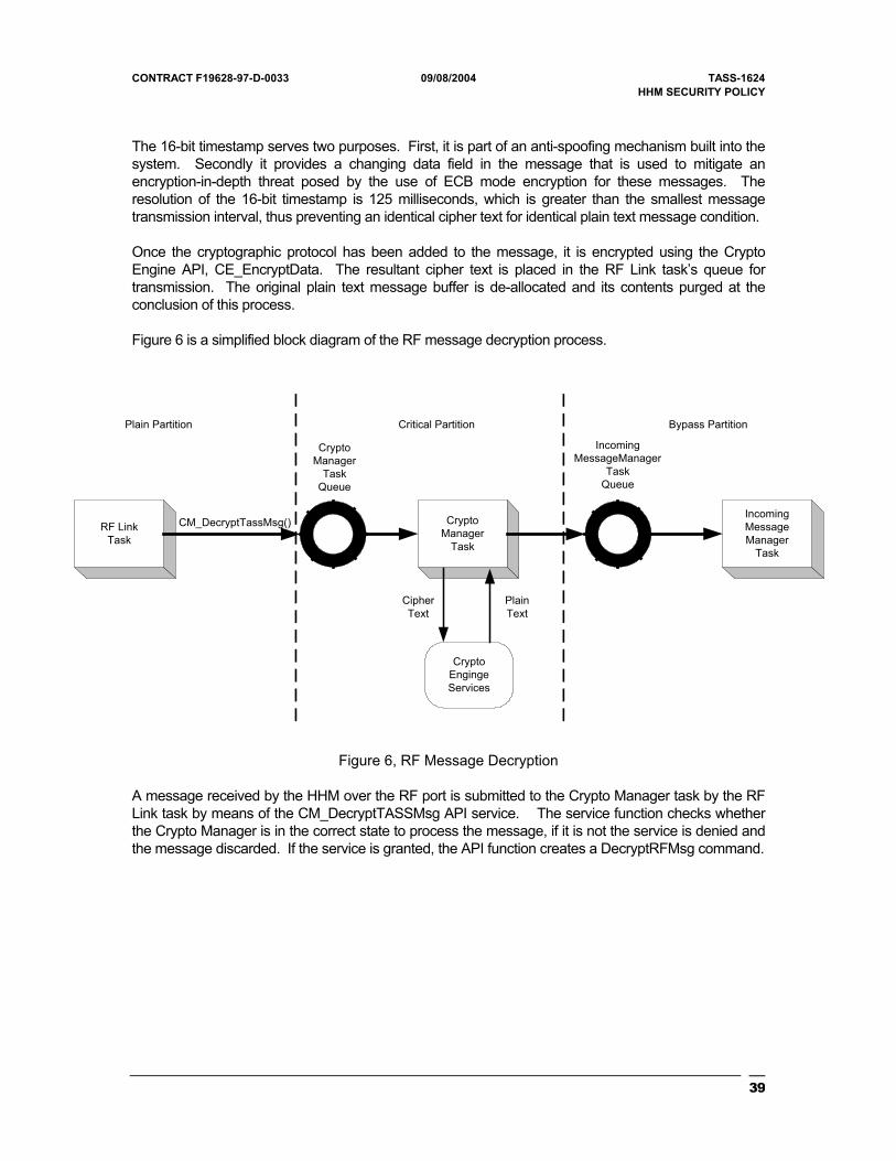
Figure 6 is a simplified block diagram of the RF message decryption process.
RF LinkTask
CryptoManager
Task
IncomingMessageManager
Task
CryptoEngingeServices
PlainText
CipherText
CryptoManager
TaskQueue
IncomingMessageManager
TaskQueue
CM_DecryptTassMsg()
Bypass PartitionCritical PartitionPlain Partition
Figure 6, RF Message Decryption
A message received by the HHM over the RF port is submitted to the Crypto Manager task by the RF Link task by means of the CM_DecryptTASSMsg API service. The service function checks whether the Crypto Manager is in the correct state to process the message, if it is not the service is denied and the message discarded. If the service is granted, the API function creates a DecryptRFMsg command.
39
CONTRACT F19628-97-D-0033 09/08/2004 TASS-1624 HHM SECURITY POLICY
• The Crypto Manager task removes the DecryptRFMsg command from its queue and starts processing the message. It first checks the key index field to determine which DEK was used to encrypt the message. If the designated DEK is stale or expired it notifies the Key Manager to command the unit that sent the message to switch DEKs. It also notifies the operator that a message with an improper DEKs was received. The Crypto Manager then performs the EBC mode decryption of the message by calling the Crypto Engine API, CE_DecryptData.
After decryption the Crypto Manager performs an 8-bit CRC check of the first 64-bit block of the message to determine if the operation was successful. If the CRC check fails the message is discarded and CM_DecryptTASSMsg is notified of the failure via a process completion event. If the CRC check passes, the Crypto Manager examines the plain text message in its anti-spoofing logic to determine whether to accept or reject the message. If the message is accepted, the cryptographic protocol layer information is removed from the message and the message is then placed for processing.
9.5 Message and Data Authentication
The HHM application software employs the FIPS 113 approved algorithm for it message and data authentication processes. The processes that employ authentication are:
• Firmware downloads
• DEKs transfers over the RS485 port.
• Over-the-Air switching of DEKs
• Cryptographic self-test.
• Entry to the Crypto Officer role.
The algorithm employed uses Triple DES in the CBC mode. The key variable used for the producing the authentication code depends on the process that requires authentication. Most of the processes use the default authentication key (KA) stored in flash memory. Authentication of DEKs transferred over the RS485 port employs the plain text DEKs itself. The initialization vector used is all zeroes, as specified in FIPS PUB 113. The data to be authenticated is run through the algorithm and the most significant 32-bits of the last encryption operation become the authentication code.
The firmware download process uses authentication to validate each firmware packet transferred over the RS485 port. The download process also authenticates the entire downloaded firmware, after it has
40
CONTRACT F19628-97-D-0033 09/08/2004 TASS-1624 HHM SECURITY POLICY
been stored in flash memory, to verify the authenticity of the entire load (the ROM firmware DAC is contained in the last downloaded packet).
The DEKs transfer processes applies message authentication to critical messages in the key transfer protocol. This was discussed in the Key manager section.
The command issued over the RF link to force TASS devices to switch from the primary to the secondary DEK must be authenticated before the command is allowed to execute. A MAC field is included in the Command Key Changeover message for this purpose.
The cryptographic self-test process utilizes data authentication to validate the correctness of the runtime firmware in SRAM. This process is discussed in the Self-Test section.
Authentication is used for entry into the Crypto Officer role by the HHM. A DAC code is generated on the password entered by the operator and compared to the Crypto Officer DAC code stored in flash memory. The values must agree before the Crypto Officer role is activated. The Crypto Officer password itself is not stored anywhere in memory.
9.6 Cryptographic Bypass
The HHM application firmware includes a cryptographic bypass capability. This capability has been included because the device can be configured to communicate over the RF port in either encrypted or unencrypted modes of operation. The bypass facility only applies to the processing of RF messages.
Before either of the first two services can be called upon to perform the bypass, the CM_BypassRequest function must be called. This function determines if the Crypto Manager’s state machine is in an allowable state for a bypass operation (BypassIdle, Warmboot, or SelfTest) and, if it is, the service sets the bypass event flag (RF_BYPASS_EN). If the service detects an invalid Crypto Manager state it denies the service (returns CM_BypassDenied).
The actual bypass process is accomplished by calling the appropriate bypass service function (CM_BypassRFMsgOut (), CM_BypassRFMsgIn()) with a pointer to the RF message information. Each of the services determines whether to allow the bypass based on the following rules:
• The Crypto Manager state machine must be in the BypassIdle state.
• The RF_BYPASS_EN event must be set.
Thus two independent flags must be set in order for the Bypass operation to occur. If either CM_BypassRFMsgOut() or CM_BypassRFMsgIn() are called and the RF_BYPASS_EN event is not set, the functions will return with an CM_BypassDenied error code. If RF_BYPASS_EN is set and the Crypto Manager is not in the BypassIdle state a fatal fault condition is declared resulting in the CryptoAlarm function being called and further execution of the firmware halted until the device is reset.
41
CONTRACT F19628-97-D-0033 09/08/2004 TASS-1624 HHM SECURITY POLICY
Before calling any of the bypass services, CM_BypassRequest must be called. This function determines if the Crypto Manager’s state machine is in an allowable state for a bypass operation (BypassIdle, Warmboot, or SelfTest) and, if it is, the service sets the bypass event flag (RF_BYPASS_EN). If the service detects an improper Crypto Manager state it denies the service (returns CM_BypassDenied).
Once a bypass operation is granted the RF message is passed to the Crypto Manager task by the service routine. In the Crypto Manager task, the RF message is transferred from its input buffer to the appropriate output buffer type before it is delivered to the queue of the destination task on the opposite side of the plain / bypass partition boundary. The RF_BYPASS_EN event flag is reset after the message bypass is completed. A bypass fail-safe timer that is set during the CM_BypassRequest() service is utilized to automatically reset RF_BYPASS_EN in the unlikely event that the bypass service routine fails to reset the flag.
9.7 Zeroization of Keys
Keys and critical security parameters (CSP) in the module are stored in flash. The keys are loaded to SRAM during bootup and stored as keylist, which contains both primary key and secondary key. Whenever keys are purged by zeroizing, the keys in flash, SRAM as well as backup keys available in flash are purged. The module takes care of zeroizing all its internal keys and critical security parameters including total erasure of firmware, which is an explicit choice by the operator on following conditions:
• When explicitly selected by the operator in the HHM menu when the device is in its Crypto Officer role. The operator can select either zeroization of DEKs, or all keys and all firmware. The operator can select whether to zeroize the local device or another HHM/CM connected to the HHMs RS485 port. The erasure of firmware requires an explicit selection from the operator and subsequent confirmation of intent before the process is performed. Total firmware erasure doesn’t occur in any other conditions specified below.
• When two keys – left and right keys on HHM pressed simultaneously and held for few seconds, the DEKs only are zeroized.
• When HHM is powered up without having battery connected for more than 90 seconds, the DEKs are zeroized. Zeroization occurs the next time that the unit is powered up.
• When HHM, which is operating in encrypted mode, is forced to operate in unencrypted mode by changing selection at menu to “No encryption”. Only the DEKs are zeroized in this case.
42
CONTRACT F19628-97-D-0033 09/08/2004 TASS-1624 HHM SECURITY POLICY
10 EMI/EMC
This product conform to The EMI/EMC requirements specified by 47 Code of Federal Regulations, Part 15, Subpart B, Class A. The lab name is F2Labs of Damascus, MD.
11 Self-Tests
The HHM software automatically performs a cryptographic self-test upon itself in response to specific events in its operation. These events are:
• Power-up initialization – I/O is disabled during power up self test.
• Prior to generating new DEKs
• Prior to any DEKs transfer process
• After a DEKs purge process
• After any other change in the HHM’s operational configuration
An operator can force the module to perform self-tests by power cycling the module.
The HHM cryptographic self-test process performs the following tests:
• Authentication of the runtime firmware in SRAM using a DAC – data authentication code.
• A Known Answer Test (KAT) of the Triple DES algorithm in EBC and CBC modes
• KAT on the RNG
• Authentication of all key variables in the KeyList
• Cryptographic bypass test
• Real-Time Clock and firmware timer test
The authentication of the runtime firmware uses the FIPS 113 approved algorithm to calculate a 32-bit DAC on all of HHM code in SRAM (the HHM executes its firmware entirely in SRAM) the result is compared to the DAC for the current version of firmware stored in flash memory. The value in flash
43
CONTRACT F19628-97-D-0033 09/08/2004 TASS-1624 HHM SECURITY POLICY
memory is calculated prior to the formal release of the version and is included in the programming of the device. If the DACs fail to match the test fails.
The KAT tests consist of encrypting a fixed plain text data vector using a test key variable stored in the KeyList for each cryptographic mode used by the algorithm (ECB and CBC). The vectors (plaintext, ciphertext, and test keys) are taken from the example vectors in ANSI X9.52, Appendix C. The CBC mode KAT also requires an initialization vector, also taken from Appendix C of ANSI X9.52. The KAT for ECB mode involves the encryption/decryption of a block of data, while the CBC mode test is performed over two blocks. The resultant cipher text from this operation is compared to the expected value. If the cipher text matches the known answer, the cipher text is then decrypted and result is compared to the original plain text. If the expected answer is not obtained at any point in the process the test fails.
The KAT on the RNG uses a fixed RNG key, fixed date time vector, and fixed seed to generate a first random result, which is compared against the previously calculated known RNG value.
As mentioned in the Key Management section of this document all key variable records stored in the KeyList include a 32-bit DAC. During the self-test process all these records are authenticated to ensure the validity of the variables.
The cryptographic bypass test calls the cryptographic bypass functions under valid and invalid conditions and determines whether the bypass is correctly granted or denied.
A failure to achieve an expected result in any of the test cases results in a failure of the entire test.
The test of the RTC and firmware timer mechanisms are included in the cryptographic self-tests because their functions are critical to the proper detection of DEKs expiration events. The test consists of setting the RTC hardware to a test date and time vector (after saving the current value) and setting a software timer to wait a specific period of time (1100 milliseconds). The timer mechanism is interrupt driven a second non-interrupt driven timing loop is started in parallel as a part of the test. If the timer expires before the software-timing loop completes the software timer test passes and the test continues. If the timer does expire before the timing loop terminates the test fails. After the timer expires the new date and time is obtained from the RTC and examined for the expected value. The test value was chosen to cause a rollover of all fields in the RTCs date/time structure.
If any of the tests performed during cryptographic self-test fails, the HHM is placed in the cryptographic alarm state.
All HHM I/O is disabled during the cryptographic self-test process, with the exception of the RTC test, which requires operation of the interrupt mechanism.
The PRNG task and CM_RandomNumber API service employ continuous random number tests to detect any faults occurring in that process. A fault in the PRNG function will result in the HHM being
44
CONTRACT F19628-97-D-0033 09/08/2004 TASS-1624 HHM SECURITY POLICY
placed into a crypto alarm state. The test is discussed in more detail in the section on pseudo-random number generation.
12 Design Assurance
All HHM source code, firmware release is tracked using Configuration Management. Microsoft SourceSafe is used as the Configuration management tool for firmware development– leading to firmware release. All documents related to firmware analysis, design and development are maintained using configuration management policy adopted by L-3 GSI through release history. The hardware components and other TASS related materials are tracked and maintained through billing materials, schematics with revision number/ date, which is again maintained by L-3 GSI configuration management system.
13 Mitigation of Other Attacks
This product is not designed to mitigate against other attacks and therefore none are specified.
14 Acronym List
ABD Air Base Defense
CBCKAT Cipher Block Chaining Known Answer Test
CM Communications Module
CMA CM Annunicator
CMC Communications Module Converter
CMR CM Repeater
CMS CM Sensor
CPU Central Processing Unit
CSP Critical Security Parameters
DEKs Data Encryption Keys
45

CONTRACT F19628-97-D-0033 09/08/2004 TASS-1624 HHM SECURITY POLICY
DLA Desk Top/Lap Top Annunciation
DSM Disconnect Service Message
ECBKAT Electronic Codebook Known Answer Test
ESM Error Service Message
HHM Hand Held Module
IP Intellectual Property
KA Key Authentication
KAT Known Answer Test
KEK Key Encryption Key
KGK Key Generating Key
KNQ Key Name Query
KNR Key Name Response
L-3 GSI L-3 Communications Government Services, Inc.
MOB Main Operating Bases
PEWD II Platoon Early Warning Device II PLD Programmable Logic Device
PRN Pseudo Random Number
RBM Relocatable Battery Module
RF Radio Frequency
RSI Request for Service Initiation
RSM Request Service Message
RTC Real-Time Clock
46
CONTRACT F19628-97-D-0033 09/08/2004 TASS-1624 HHM SECURITY POLICY
47
RTOS Real-Time Operating System
SRAM Static Random Access Memory
TASS Tactical Automated Security System
PEWD Platoon Early Warning Device II
SOH State Of Health
CSCI Computer Software Configuration Item
PWB Printed Wired Board
RTOS Real Time Operating System
DSP Digital Signal Processor