Embed Size (px)
Citation preview

New Zealand Telecommunications Forum
TCF Premises Wiring Cable Installers Guidelines for Telecommunication Services
Version: 5.0 Approved Date: September 2015
"© 2015 The New Zealand Telecommunications Forum Inc. Except as provided by the Copyright Act 1994, no part of this material may be reproduced or stored in a retrieval system in any form or by any means without the prior written permission of the New Zealand Telecommunications Forum Inc."

TCF Premises Wiring Cable Installers Guidelines Approved 2015 Page 2 of 60
V DATE AUTHOR COMMENTS
2.2 February 2010 TCF Endorsed by the TCF Board.
3.0 October 2010 TCF Changes made to incorporate UFB and multi‐dwelling premises.
3.1 November 2010 TCF Changes made to incorporate UFB and multi‐dwelling premises.
3.2 – 3.3 December 2010 TCF Changes made to incorporate UFB and multi‐dwelling premises.
3.4 – 3.6 January – February 2011
TCF Review by Working Party
3.7 March 2011 TCF Final draft for public consultation
3.8‐9 May 2011 TCF Final for TCF Board Endorsement
4.0 31 May 2011 TCF Approved
4.1 – 4.9 June 2014 TCF Industry review
4.10 Oct 2014 TCF Restructured format
4.10‐4.17 April 2015 TCF Redrafting
4.18 April 2015 TCF Final Draft
4.19 April 2015 TCF Working Party Feedback
4.20 May 2015 TCF Final For Public Consultation
4.21 August 2015 TCF Incorporate public consultation feedback
5.0 September 2015 TCF Approved by the TCF Board
TCF Premises Wiring Cable Installers Guidelines Approved 2015 Page 3 of 60
CONTENTS
A. INTRODUCTION ........................................................................................... 5
B. BACKGROUND ............................................................................................ 5
C. PURPOSE .................................................................................................. 5
D. APPLICABILITY ............................................................................................ 6
E. OBJECTIVES AND SCOPE ................................................................................. 6
16. OBJECTIVES ................................................................................................... 6 17. SCOPE ........................................................................................................ 6
F. COMPLIANCE ............................................................................................. 8
G. INDUSTRY STANDARDS .................................................................................. 8
H. DEFINED TERMS .......................................................................................... 9
I. SYSTEM DESIGN RECOMMENDATIONS ................................................................ 14
22. SYSTEM OBJECTIVES .......................................................................................... 14 23. WIRING ARCHITECTURE ...................................................................................... 14 24. GENERIC CABLING SYSTEM COMPONENTS ...................................................................... 15 25. MAJOR SYSTEM COMPONENTS ............................................................................... 18 26. SERVICE LEAD‐IN ............................................................................................ 18 27. EXTERNAL TERMINATION POINT (ETP) ........................................................................ 19 28. DEMARCATION POINT ........................................................................................ 21 29. MULTI DWELLING UNIT (MDU) .............................................................................. 21 30. HOME DISTRIBUTOR ......................................................................................... 23 31. POWER SUPPLY .............................................................................................. 26 32. GENERIC CABLING ........................................................................................... 26 33. DUCTING ................................................................................................... 29 34. TELECOMMUNICATIONS OUTLET (TO) ......................................................................... 30
J. INSTALLATION GUIDELINES ............................................................................. 33
38. SAFETY REQUIREMENTS ...................................................................................... 33 39. TELECOMMUNICATION WIRING PRACTICES ..................................................................... 34 40. CROSS‐CONNECTIONS AND COMMONING OF TO’S FOR TRADITIONAL ANALOGUE TELEPHONE SERVICE ............... 39 41. CONNECTION OF BROADBAND SERVICES ....................................................................... 39 42. MOUNTING HARDWARE ...................................................................................... 40 43. FACEPLATES AND SOCKET ORIENTATION ........................................................................ 40 45. FIBRE TERMINATION ......................................................................................... 41
K. INSTALLATION TESTING ................................................................................. 44
52. CABLE INSTALLER’S OBLIGATIONS .............................................................................. 44 53. DAMAGE ................................................................................................... 44 54. VISUAL INSPECTION .......................................................................................... 44 56. QUALIFICATION TESTING ..................................................................................... 47 57. QUALIFICATION TEST INSTRUMENTS ........................................................................... 47 58. TESTING AND CERTIFICATION OF COAXIAL CONNECTIONS ......................................................... 49
L. RECORDS MANAGEMENT ............................................................................... 50
59. GENERIC CABLING MANAGEMENT ............................................................................. 50

TCF Premises Wiring Cable Installers Guidelines Approved 2015 Page 4 of 60
60. INSTALLATION RECORDS ...................................................................................... 52 61. COMPLIANCE STATEMENT DOCUMENTATION ................................................................... 52
M. SPECIAL SITUATIONS .................................................................................... 52
N. APPENDIX ................................................................................................ 53
APPENDIX 1: INTERIM STEPS FOR LEGACY WIRING AND XDSL INTERFERENCE ............................................ 53 APPENDIX 2: NEW HOME SCHEMATIC DIAGRAMS .................................................................... 54 APPENDIX 3: FOR FURTHER INFORMATION ........................................................................... 59

TCF Premises Wiring Cable Installers Guidelines Approved 2015 Page 5 of 60
A. INTRODUCTION
1. The New Zealand Telecommunications Forum (“TCF”) established the Premises Wiring Working Party to provide recommendations on the provision and maintenance of Premises Wiring in residential, Single Dwelling Unit (SDU) and Multi‐Dwelling Unit (MDU) premises in New Zealand to support telecommunication services offered over fibre and copper lines.
2. Recent developments in technologies and services, and the Governments Ultra‐fast Broadband
initiative now require extensive wiring and cross‐connect facilities to be an essential part of the modern home.
3. The purpose for these recommendations is to inform cable installers on the principles and practices for
planning, installing and maintaining a Generic Cabling system to provide an open, flexible platform for current and future telecommunication services within the premises.
4. It is recommended that developers of either subdivisions or MDUs (residential or commercial premises) should contact the Access Network Provider at the preliminary stage of their planning to ensure that the correct capacity is provided to meet telecommunication requirements.
B. BACKGROUND
5. There is a clear trend towards increasing levels of integration between the various services and applications in the home. Not just telephony and data, but broadcast TV, audio, video, gaming, security and building control services are being brought together via a general purpose or “generic” cabling system.
6. The development of the “2‐wire” telephone wiring code of practice in 1990s led to the widespread use
of 2‐pair telecommunications cable in most homes and small businesses. That code has proved satisfactory for supporting current telecommunications services, including telephone and broadband delivery.
7. xDSL services use the same frequency band as radio broadcasting, so under certain circumstances each
may interfere with each other. Normally xDSL is carried by wire whereas radio reception is by radio waves traveling through space. If “2‐wire” or “3‐wire” telephone wiring is used there is a high chance that the xDSL signal will be radiated from the cable and cause interference to AM radio reception. If properly terminated UTP is used, as outlined in this Document, then telecommunication services stay within the UTP cable and do not cause interference to radio.
8. However fibre optic network services as well as in‐home network (LAN) and entertainment applications
require a level of functionality and performance that traditional residential, SDU and MDU premises wiring cannot provide.
9. Although higher performing business grade wiring systems, typically Unshielded Twisted Pair (UTP) Cat5
and above, have been used in many new homes and offices for some years, most homes have continued to install the much lower performing 2‐wire system for telecommunications‐based services. That choice of cabling structure will limit the ability of those occupying the home to access and enjoy future network as well as in‐home entertainment and control applications.
10. While alternative networking technologies, such as WiFi and G.hn (Home Grid) do exist, and are often
useful extensions of wired networks, they cannot provide the same levels of consistency, reliability and security that structured wiring provides.
C. PURPOSE
11. The purpose of this document is to outline the Telecommunications Industry’s recommendations regarding the provision of Generic Cabling in residential, SDU and MDU premises to Interested Parties

TCF Premises Wiring Cable Installers Guidelines Approved 2015 Page 6 of 60
and to define a set of recommendations which will provide good long‐term performance and reliability of Telecommunication Services for the New Zealand consumer.
12. This document deals with requirements for direct connection to Service and Access Network Providers
networks.
13. This document is intended for use by Interested Parties involved in Generic Cabling installations for Telecommunications Services namely:
13.1. Consumers. Including building owners; 13.2. Building industry providers (architects, builders, developers, etc.); 13.3. Suppliers of technology (electrical contractors, equipment suppliers, etc.); 13.4. Retail Service Providers; and 13.5. Access Network Providers.
D. APPLICABILITY 14. This document is applicable to all residential, SDU and MDUs being constructed and undergoing major
renovations.
15. The recommendations are also applicable to those premises that are not yet served by fibre optic or xDSL networks, including rural areas. The availability of economical cellular phone data services and satellite data services is expected to become more widespread and it would be advantageous for all premises to be suitably cabled to make use of those services.
E. OBJECTIVES AND SCOPE
16. Objectives
16.1. The objectives of this document is to define a set of recommendations which will provide good long‐term performance and reliability for the New Zealand consumer by: 16.1.1 Recommending minimum requirements regarding the provision of Generic Cabling
to support Telecommunications Services in residential, SDU and MDU premises in New Zealand.
16.1.2 Setting out best practice management principles that parties involved in the design,
installation and maintenance of Generic Cabling and facilities should:
a) Identifying the rights and responsibilities of Interested Parties;
b) Providing guidelines to providers of Generic Cabling to assist them to comply with their legal obligations and with this document;
c) Carry out adequate testing of the Generic Cable installation to ensure that it is working, and complete adequate documentation of the testing,
d) Achieving a balance between industry and End‐User interests;
e) Promoting the informed, fair and safe use of Generic Cabling; and
f) Being technology neutral.
17. Scope 17.1. This document addresses requirements for the support of Telecommunication Services that a
Retail Service Provider may deliver over the Public Switched Telephony Network (PSTN), xDSL, Ethernet, Radio Frequency (RF) or Fibre To The Premises (FTTP) network to residential, SDU and MDU premises, as illustrated in Figure 1 below.

TCF Premises Wiring Cable Installers Guidelines Approved 2015 Page 7 of 60
Figure 1: Scope of Premises Wiring
17.2. This document specifies Generic Cabling as defined by AS/NZS 15018 and AS/NZS 1367, for two groups of applications:
a) Information and Communications (Telecommunications) Technologies (ICT); and
b) Broadcast and Communications Technologies (BCT).
17.3. The document specifies Generic Cabling that comprises one or more of the following:
a) Twisted pair (TP) copper cabling;
b) coaxial cabling; and
c) fibre optic cabling.
17.4. The Generic Cabling practices and recommendations detailed in this document can also apply
to commercial or business premises where Generic Cabling systems are appropriately utilized.
18. Exclusions from Scope 18.1. The following items are excluded from scope;
a) Electrical Wiring and in‐home power line carrier technology;
b) Customer Premises Equipment (CPE);
c) The use of Wireless networking technologies (e.g. WiFi);
d) Home automation, security systems, and entertainment systems and control applications within residential, SDU and MDU premises; and
e) Types of cable for control systems for lighting, heating control, entertainment and security.

TCF Premises Wiring Cable Installers Guidelines Approved 2015 Page 8 of 60
F. COMPLIANCE
19. This document outlines the Telecommunications Industry’s recommendations for the design, installation and maintenance of Generic Cabling at a Residential, SDU and MDU premises to support telecommunication services over fibre and copper lines.
20. Any Generic Cabling installations for Residential, SDU and MDU premises should comply with the relevant industry standards, legislation or Commerce Commission determinations and their subsequent revisions. Refer to section G.
G. INDUSTRY STANDARDS
21. This document supports the recommendations of the Australia and New Zealand Standard for generic cabling for homes (AS/NZS 15018) and for Coaxial and Fibre‐Optic distribution of Analog and Digital Television and Sound Signals in Single and Multiple Dwellings (AS/NZS 1367). It also sets out the functional specifications for the provision of Generic Cabling to support Telecommunications Services in New Zealand Residential, SDU and MDU premises.
Title Description
AS/NZS 1367:2007 Coaxial cable and optical fibre systems or the RF distribution of analogue and digital television and sound signals in single and multiple dwelling installations
AS/NZS 3000:2007 Electrical Installations
AS/NZS 3080:2013 Telecommunications installations ‐ Generic cabling for commercial premises
AS/NZS 3084:2003 Telecommunications installations ‐ Telecommunications pathways and spaces for commercial buildings
AS/NZS 3085:2004 Telecommunications installations ‐ Basic requirements
AS/NZS 3112:2011 Approval and test specification ‐ Plugs and socket‐outlets
AS/NZS ISO / IEC 15018:2005 Information technology ‐ Generic cabling for homes
AS/NZS ISCO / IEC 24702:2007 Telecommunications installations ‐ Generic cabling ‐ Industrial premises
IEEE 802.3 2012 Power over Ethernet
Fair Trading Act 1986
Consumer Guarantees Act 1993
TCF Premises Wiring Cable Installers Guidelines Approved 2015 Page 9 of 60
H. DEFINED TERMS In this Document, unless the context otherwise requires: “Access Network Provider” (ANP) means the Party to whose network an access line is directly connected and over which services are supplied. Note that an ANP may also be an Access Service Wholesaler and/or a Retail Service Provider. “Accessory" any device, not itself directly providing a telecommunications function, which is plug connected to the premises wiring. “APC” refers to Angle Polished Cut. “Balanced Pair Cable” Cable consisting of one or more metallic symmetrical cable elements (twisted pairs or quads) also known as Cat5e and above, as referenced in the ISO/IEC 11801. “BICSI” (Building Industry Consulting Services, International) is an association that promotes data cabling standards. “BT jackpoint” means any jackpoint which mates with a plug to BS 6312 standard. “Carrier” means an entity that operates:
(a) A public switched telephone network (or a functionally equivalent system) that originates, transits or terminates calls; and/or
(b) A public data network. A Person may be both a Carrier and a Service Provider. If a Party has more than one network, it can be classified as more than one Carrier.
“Category” refers to the rated design performance of a particular cable. “Chorus” refers to Chorus New Zealand Ltd. “Chorus permit”, hardware or cable marked with a “Chorus permit” label to indicate that it complies with Chorus specifications for connection to its local copper or fibre access network. A Chorus permit is a prerequisite to the granting of a Spark New Zealand Telepermit™.
“Clause” refers to a clause in this Document. “Cross‐connection: any arrangement which enables a jackpoint to be associated with a specific service. “Commoning” means being a facility to wire multiple phone ports in parallel. “Customer premises equipment (CPE)” any telecommunications terminal equipment connected to the customer’s wiring, other than CLNE. “Customer” means a person who has a bona fide Billing Relationship with a Service Provider in respect of a Telecommunication and/or Broadcast Service. The Customer is the end user (i.e. not a wholesale customer). “Customer‐located network equipment (CLNE)” access network provider / service provider network terminating equipment required to provide a specific service and located within the customer’s premises on the customer’s side of the network demarcation point. “Daisy‐chain (or loop) wiring” means a common form of wiring where a cable to one jackpoint is connected to another cable to the next jackpoint.
TCF Premises Wiring Cable Installers Guidelines Approved 2015 Page 10 of 60
“Demarcation point” The network demarcation point is at which the lead‐in cable enters the customer’s building and, usually, also the point at which the customer’s wiring is connected to the network lead‐in cable, and is detailed in section 28.
To avoid any doubt, the service delivery point is on the customer side of the CLNE. “External cable” cable intended for installation outside buildings, exposed to the weather or ground contact, and provided with an appropriate protective sheath. “External Terminating Point (ETP)” means external termination point which is an external box, in which the lead‐in cable is connected to the internal building wiring. It is also (incorrectly) known as External Test Point, the Network Termination Device or demarcation point, when provided. “Fibre” a thin, flexible, transparent fiber that acts as a waveguide, or "light pipe", to transmit light between the two ends of the fiber. It is typically made from glass. Two standards are used when specifying fibre: ITU‐T G.657 (bend insensitive) and ITU‐T G.652 “Generic cabling” often referred to as “structured cabling”, a cabling system capable of supporting a wide range of ICT and BCT services which is installed without detailed knowledge of the required applications. As referred to in section 5 of the AS/NZS 15018 “Hardware (or line hardware)” any fixed wired device other than CPE. “Home Distributor” the central point of a generic cabling system, consisting of a cabinet or cupboard housing cross‐connection and test facilities for the premises cabling and associated services. ‘Insulation Displacement Connector’ (IDC) commonly used to terminate wiring at hardware. “Inside cable” telecommunications cable intended only for use within a building. “Interested Parties” includes the following: Architects, Specifiers, Installers, Cablers, Security System providers, and Home Automation specialists, Electrical Contractors, Builders, Consumers, Developers, Equipment Suppliers and Service Providers. “ITU‐T G.hn” is a standard promoted by the HomeGrid Forum that allows existing power, telephony and coaxial wiring to be used for providing Ethernet services. “Jackpoint” is any type of outlet used for plug‐connecting CPE. “Jumper” refers to a hard‐wired cross‐connection (not using plugs and sockets). “Keystone” a keystone module is an industry standard type of telecommunications outlet used in residential and business environments. The systems consist of a modular faceplate to which outlets are mounted.
“Lead‐in cable” the cable used from the street to the customer’s premises. “Line grabbing” a function of series connected CPE which disconnects other wiring and CPE from the line to either terminate or initiate a call on a voice line.
Examples are medical and security alarms programmed to call a pre‐determined number when triggered independent of whether the line is already in use.
“Low Voltage (LV)” any voltage exceeding 42.4 V peak AC or 60 V DC, but not exceeding 1000 V peak AC or 1500 V DC. 230 V wiring is defined as Low Voltage and must be segregated from telecommunications wiring. “May” refers to matters which are optional.

TCF Premises Wiring Cable Installers Guidelines Approved 2015 Page 11 of 60
“Multi‐dwelling Unit” (MDU) includes semi‐detached, apartments, townhouses, gated communities and assisted‐living facilities that share a common property boundary. MDU facilities may be under a single roof or they may consist of multiple buildings on a residential campus. MDUs may include only residential units or they may have residential units along with commercial and retail spaces. The BICSI defines 3 types of MDUs1:
(a) Low‐rise MDUs: Each unit has access to the ground level and also has a roof line such as
townhouses and semi detached dwellings. (b) Mid‐rise MDUs: These include duplexes, two storey apartments and other building styles in
which units are stacked upon one another.
(c) High‐rise MDUs: High‐rise MDUs most closely resemble large commercial buildings with few
units having direct access to the roof line or ground floor. “Must” refers to matters which are essential for compliance with the Document. “New Zealand Telecommunications Forum” or “TCF” means the New Zealand Telecommunications Forum Incorporated Society of New Zealand.
“Optical Network Termination (ONT)” a unit provided to terminate its optical fibre lead‐in cable. “Pair” any set of two wires, which are usually twisted in a cable, used to provide a circuit. “Party” means a Person bound by this Document under the Telecommunications Act or a Person signed up to this Document. “Patch cord” a means of cross‐connection using plug‐ended cords between the socket terminating the associated jackpoint cable and the socket used for the service being connected. “Person” means a legal person and includes a company and any other legal entity. “Primary Home Distributor (PHD)”, provides a point of connection to external network services and also to local equipment. In the case of an MDU this is referred to as a building frame. “Premises” is a single building or structure located on a defined geographical site. A premises can contain one potential End User, e.g., stand alone house), or more than one potential End User e.g., apartment building or high rise office building. “Premises Wiring” is the physical deployment of Generic Cabling principles. “Private Dwelling” means any private dwelling that is both fixed in location and of durable or permanent construction. A private dwelling accommodates a person or a group of persons, but is not available to the public. This includes: houses, flats, and apartments; residences attached to a business or institutions; baches, cribs, and holiday homes; and dwellings of the above types that are under construction. Garages; caravans, cabins and tents; vehicles; vessels; are also included. Exclusions: a private dwelling with 6 or more boarders or lodgers should be classified as a boarding house2. “RGW” refers to residential gateway which may be provided by the Retail Service Provider.
1 Excerpt from ‘Residential Network Cabling’ by BICSI, http://books.google.co.nz/books?id=EDSW8ZXByAcC&pg=PA420&lpg=PA420&dq=bicsi+mdu&source=bl&ots=uInJq1bqgA&sig=QVWN_b3bqTsmYi83H69jCHvvhFo&hl=en&ei=QjxHTbfGAdDJcYefudUD&sa=X&oi=book_result&ct=result&resnum=5&ved=0CCwQ6AEwBA#v=onepage&q&f=false Accessed 1 February 2011 2 Abridged, Statistics New Zealand

TCF Premises Wiring Cable Installers Guidelines Approved 2015 Page 12 of 60
“Residential‐type” a general term to describe wiring systems intended mainly for residential customers’ premises, but also commonly used for small business applications. “Retail Service Provider” (RSP) means any person providing a Telecommunication and/or Broadcast Service to a Customer and who has the Billing Relationship with the Customer for that service. “RJ 45” a generic term used to describe the 8‐way modular socket or associated plug originally used in North America and now standardised internationally3. “Series CPE” any CPE connected in the path between other CPE and the network. “Service Line” is a physical bearer that supports telephony, data and video or any combination thereof. “Secondary Home Distributor (SHD)” connects the primary home cabling to secondary home cabling and provides connections to outlets or unit Home Distributors. “Service Provider (SP)” means any person providing a Telecommunication and/or Broadcast Service to a Customer and who has the Billing Relationship with the Customer for that service. The same person may be both an Access Network Provider and a Service Provider. In this document the Service Provider is referred to as the Retail Service Provider. “Should” refers to matters which are optional. “Shall” refers to matters which are essential for compliance with the Document. “Single Dwelling Units (SDUs)” means a premises containing one residential or commercial occupant/person within its boundary. “Socket” the term used to describe the specific type of socket component incorporated in “jackpoint” or “telecommunications outlet”. “Star wiring” an arrangement whereby each jackpoint is separately cabled to a central point, where cross‐connect facilities may be provided. “Shielded Twisted Pair (STP)” balanced pair cable with some form of shielding for improved EMC compatibility. “Structured cabling multi‐purpose high performance cabling systems installed to AS/NZS 3080 or equivalent standards. “Spark” refers to Spark New Zealand Ltd including its subsidiaries. “Telecommunication” is the conveyance by electromagnetic means from one device to another of any encrypted or non‐encrypted sign, signal, impulse, writing, image, sound, instruction, information, or intelligence of any nature, whether for the information of any person using the device or not; but excluding any conveyance that constitutes broadcasting. “Telecommunications Act” means the Telecommunications Act 2001 as amended from time to time. “Telecommunications Cabling” refers to cable for voice and data (the data may be related to video, security, audio, and home automation control). “Telecommunications Outlet (TO)” means the international term to describe any type of socket or jackpoint into which terminal equipment may be connected.
3 Refer to the IEC 60603-7 and related standards.

TCF Premises Wiring Cable Installers Guidelines Approved 2015 Page 13 of 60
“Telecommunication(s) Service” refers to any good, service, equipment and/or facility that enables or facilitates Telecommunication. “Telepermit™” hardware or cable marked with a “Telepermit” label to indicate that it complies with Spark New Zealand’s specifications for connection and use on their network and with the designated service. A Chorus permit as a prerequisite to the granting of a Telepermit. “Telephone hub” any form of Commoning facility, typically used to provide terminations where multiple TO’s are to access the same telephone line. “Test termination” a sealed resistor/capacitor combination usually fitted within an ETP to provide a remote line test capability independent of whether any CPE is connected to that line. “TNV (Telecommunications Network Voltage)” a non‐hazardous class of voltage for safety rating purposes, subdivided into three sub‐classes.
TNV‐1 normal operating voltages do not exceed SELV (Safety Extra Low Voltage, which does not exceeding 42.4 V peak a.c or 60 V d.c.) but could be subject to over‐voltages from a network.
TNV‐2 normal operating voltages do not exceed SELV and are not subject to network over‐voltages.
TNV‐3 normal operating voltages do exceed SELV and are subject to network over‐voltages. Because of ringing voltage and the possibility of mains contacts or lightning transients, a PSTN line and the wiring directly connected to it are rated at TNV‐3. Wiring carrying Ethernet is rated at SELV.
“Twisted Pair (TP)” is a common term to refer to UTP (unshielded twisted pair). “Two‐wire (2‐wire)” the present standard BT jackpoint system where one pair interconnects all 2‐wire TO’s, each of which incorporates a capacitor to ring older 3‐wire connected CPE. “Unit Home Distributor (UHD)” which, in a multi‐dwelling unit, connects to external network services and provides connections to outlets in an individual dwelling unit “UTP (Unshielded Twisted Pair)” the more commonly used type of balanced pair cable (as distinct from STP) in New Zealand. “Voiceband” frequencies up to 4 000 Hz and, in particular, the nominal frequency range 300 Hz – 3400 Hz used for voice transmission.

TCF Premises Wiring Cable Installers Guidelines Approved 2015 Page 14 of 60
I. SYSTEM DESIGN RECOMMENDATIONS
22. System objectives
22.1. An objective of any residential wiring system is for all outlets (Telecommunications Outlet) to be general purpose. Telecommunication Outlets (TO) can support a range of applications, depending upon the appliance plugged into it and the service the TO is patched to at the Home Distributor. A TO is therefore an “access point” used to access common network and in‐home applications, including:
a) Telephony services ‐ PSTN, VOIP, Fax;
b) Wireless Services ‐ Wireless (DECT) Telephones as well as WiFi;
c) Local Area Networks ‐ 10Mbits/sec ‐ 10Gbits/sec Ethernet.
23. Wiring Architecture
23.1. The recommended wiring for a residential Generic Cabling Systems is a star‐wired architecture
using high performance cables and TO sockets. This is significantly different from traditional analogue telephone wiring which in many cases is wired in a daisy‐chain fashion using voice‐grade cabling and outlets. The differences in architecture are illustrated by Figure 2.
Figure 2: Wiring Topology Types
23.2. The data cabling will use the star configuration to enable each TO to be connected to a separate port on the Residential Gateway or router.
23.3. Generic Cabling that is used for connecting telephones, will use a Telephone Hub at the star
connection box (refer Figure 2 above) to allow all telephones to access a single incoming PSTN line.
23.4. Devices which use line grabbing functions, such as medical, fire and burglar alarms, need to be
connected so that they can seize the lines and make calls even if the telephone line is being
TCF Premises Wiring Cable Installers Guidelines Approved 2015 Page 15 of 60
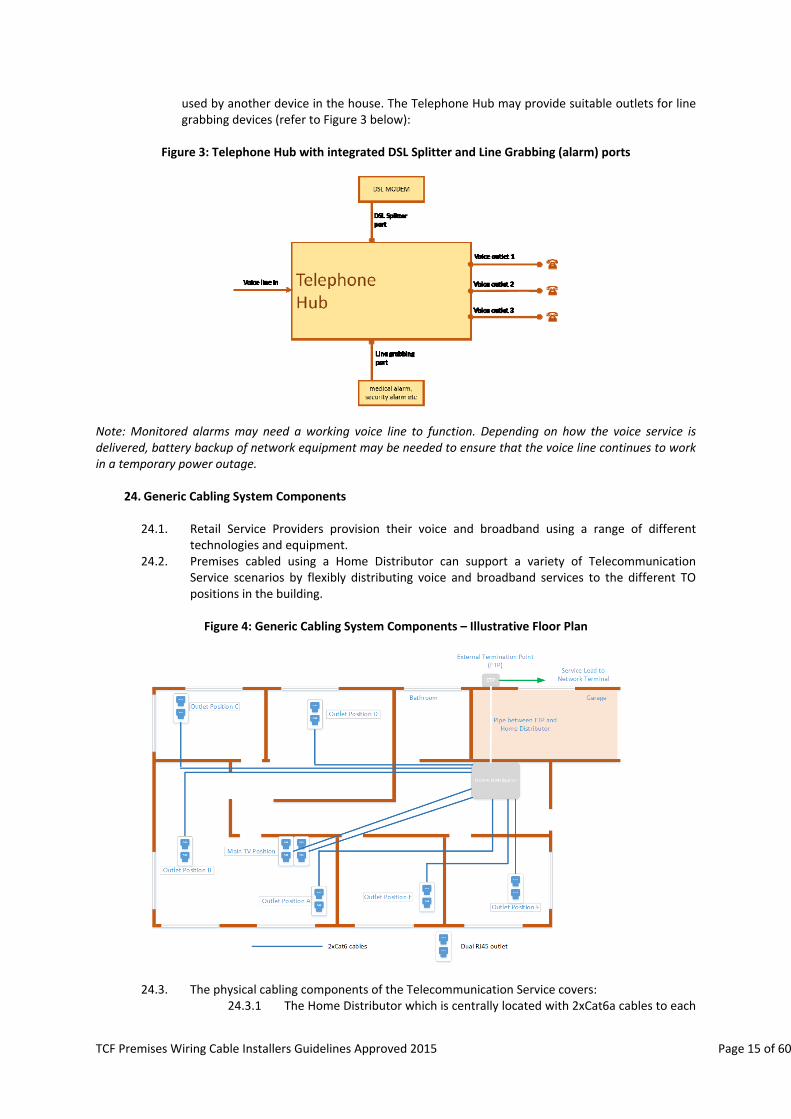
used by another device in the house. The Telephone Hub may provide suitable outlets for line grabbing devices (refer to Figure 3 below):
Figure 3: Telephone Hub with integrated DSL Splitter and Line Grabbing (alarm) ports
Note: Monitored alarms may need a working voice line to function. Depending on how the voice service is delivered, battery backup of network equipment may be needed to ensure that the voice line continues to work in a temporary power outage.
24. Generic Cabling System Components
24.1. Retail Service Providers provision their voice and broadband using a range of different
technologies and equipment. 24.2. Premises cabled using a Home Distributor can support a variety of Telecommunication
Service scenarios by flexibly distributing voice and broadband services to the different TO positions in the building.
Figure 4: Generic Cabling System Components – Illustrative Floor Plan
24.3. The physical cabling components of the Telecommunication Service covers: 24.3.1 The Home Distributor which is centrally located with 2xCat6a cables to each
TCF Premises Wiring Cable Installers Guidelines Approved 2015 Page 16 of 60
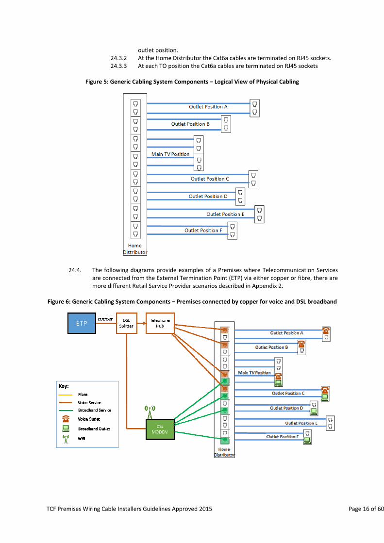
outlet position. 24.3.2 At the Home Distributor the Cat6a cables are terminated on RJ45 sockets. 24.3.3 At each TO position the Cat6a cables are terminated on RJ45 sockets
Figure 5: Generic Cabling System Components – Logical View of Physical Cabling
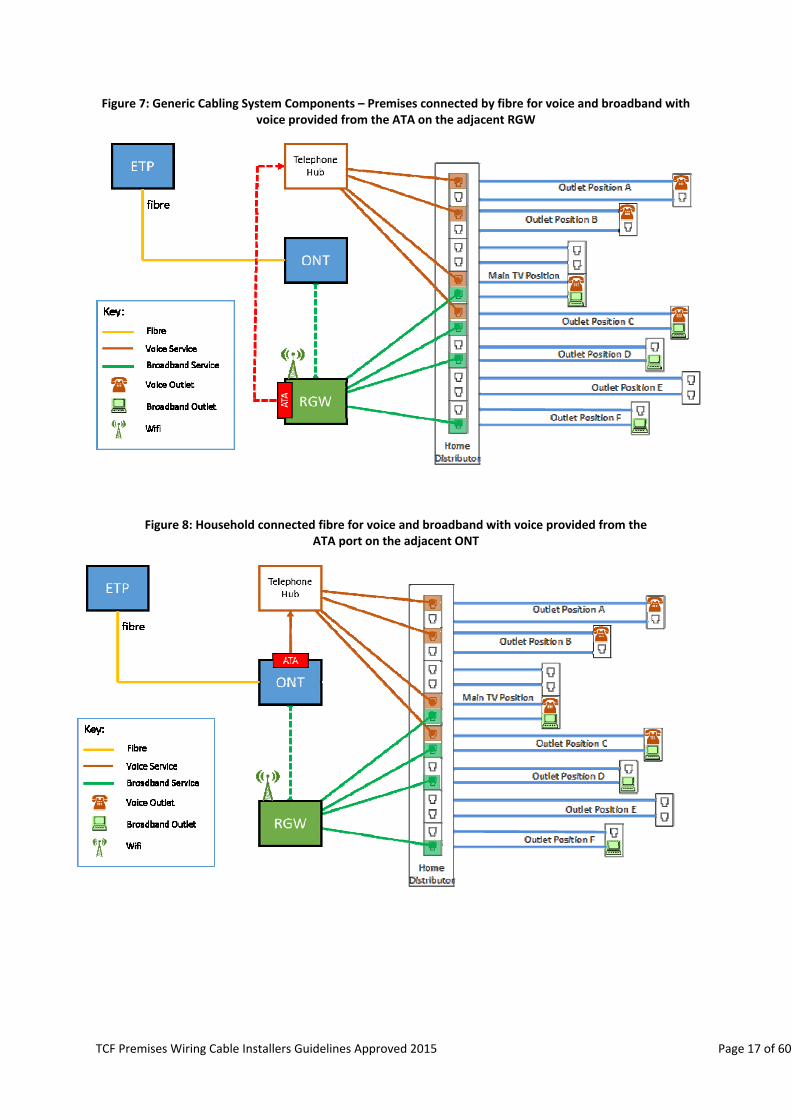
24.4. The following diagrams provide examples of a Premises where Telecommunication Services are connected from the External Termination Point (ETP) via either copper or fibre, there are more different Retail Service Provider scenarios described in Appendix 2.
Figure 6: Generic Cabling System Components – Premises connected by copper for voice and DSL broadband
TCF Premises Wiring Cable Installers Guidelines Approved 2015 Page 17 of 60
Figure 7: Generic Cabling System Components – Premises connected by fibre for voice and broadband with voice provided from the ATA on the adjacent RGW
Figure 8: Household connected fibre for voice and broadband with voice provided from the ATA port on the adjacent ONT
TCF Premises Wiring Cable Installers Guidelines Approved 2015 Page 18 of 60
25. Major System Components
25.1. The key functional elements of a Generic Cabled home are:
Prescribed elements: a) Service Lead‐In ‐ the connection to an Access Network Provider (ANP); b) External Termination Point (located outside the premises); and c) Demarcation Points.
Discretionary elements:
a) Home Distributor including patch cables and voice distribution; b) Power supplies; c) Internal premises Cabling; d) Ducting; and e) Telecommunications Outlet ‐ RJ45 & coaxial F connectors.
26. Service Lead‐In
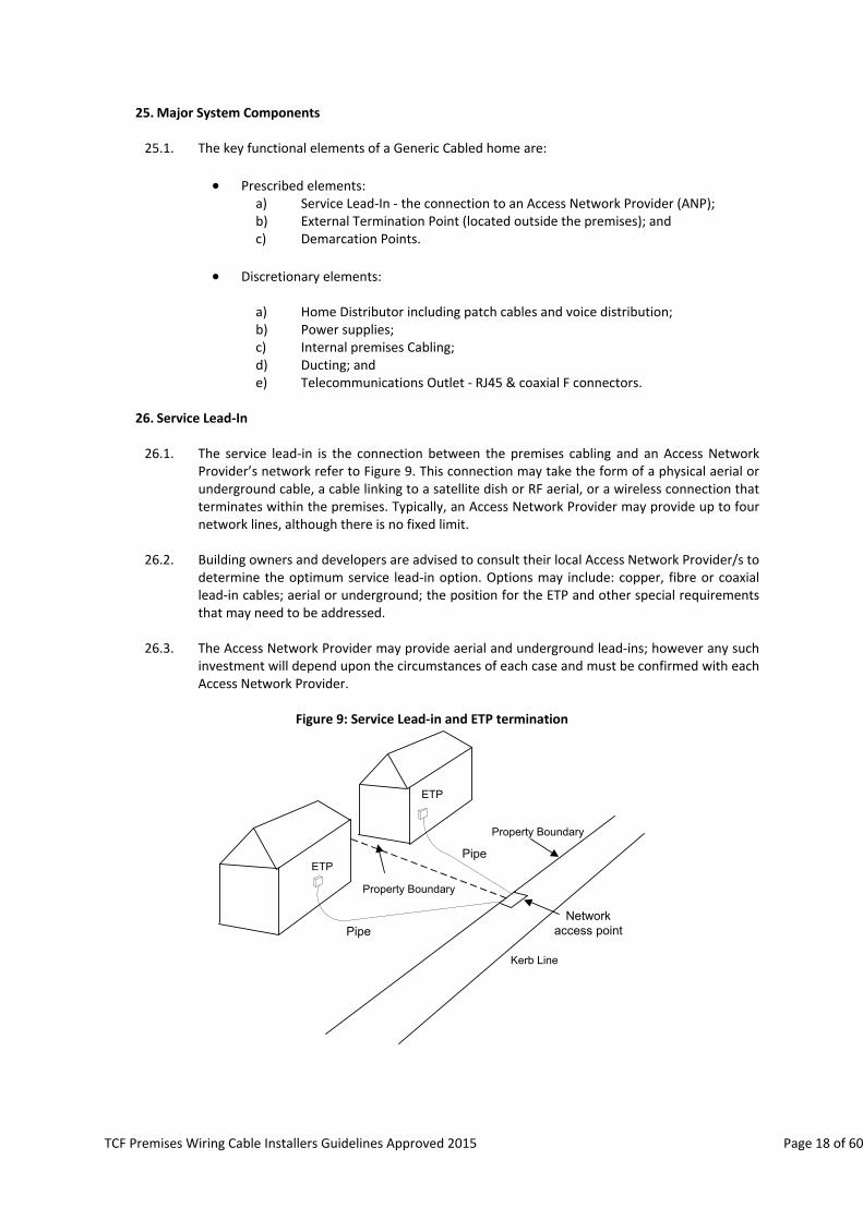
26.1. The service lead‐in is the connection between the premises cabling and an Access Network
Provider’s network refer to Figure 9. This connection may take the form of a physical aerial or underground cable, a cable linking to a satellite dish or RF aerial, or a wireless connection that terminates within the premises. Typically, an Access Network Provider may provide up to four network lines, although there is no fixed limit.
26.2. Building owners and developers are advised to consult their local Access Network Provider/s to determine the optimum service lead‐in option. Options may include: copper, fibre or coaxial lead‐in cables; aerial or underground; the position for the ETP and other special requirements that may need to be addressed.
26.3. The Access Network Provider may provide aerial and underground lead‐ins; however any such
investment will depend upon the circumstances of each case and must be confirmed with each Access Network Provider.
Figure 9: Service Lead‐in and ETP termination
ETP
ETP
Property Boundary
Kerb Line
Pipe
Pipe
Property Boundary
Network access point
TCF Premises Wiring Cable Installers Guidelines Approved 2015 Page 19 of 60
26.4. Trenching for underground lead‐in cables 26.4.1 The provision of suitable trenching for all services is the responsibility of the
premises owner or building contractor acting on the premises owner’s behalf. It is strongly recommended that the contractor or his agent consults with the Access Network Provider and the premises owner to determine the most appropriate point on or in the building to fit the Network Termination (typically an External Termination Point or “ETP”) and the route for the trench.
26.4.2 The location and design of the trench must meet the requirement of the Access Network Provider. Failure to meet these requirements may prevent the Access Network from connecting to the premise using the trench and result in the need for further work.
26.4.3 Lead‐in cable or pipe may share a common trench with other services, subject to adequate protection against hazards or damage.
26.4.4 Where a gate entry system is to be installed for a new building, especially if it has a long driveway, the recommended approach is to co‐ordinate the lead‐in and gate entry cable installation with other building services work. This allows the several services concerned to share the lead‐in cable trench, which is paid for by the customer. The gate control installation contractor can then run the necessary control and communication wiring before the trench is closed. AS/NZS3000 restrictions on the sharing of trenches, specifically separation distances (depths), must be observed. It may be preferable to have separate trenches.
26.4.5 The building owner or building contractor acting on the owner’s behalf is responsible for back‐filling the lead‐in trench, ensuring there is at least 300mm cover over the lead‐in pipe.
26.4.6 In most suburban cases, the network access point is located on alternate section boundaries at the road frontage and the lead‐in cable is run across the premises owner’s land to the ETP.
26.4.7 In the case of back‐sections, without a public road frontage, it may be necessary for the lead‐in to pass over or under land owned by parties other than the property owner concerned. In such cases, those parties will be required to formally agree to such crossings before any installation work can begin.
26.4.8 Neighbours crossings will usually require a formal easement to be written into land records, so subsequent owners of the land cannot demand the cable is removed or hinder access to it for maintenance, replacement or upgrade purposes.
26.4.9 MDUs may require individual lead‐ins to each unit (e.g. low rise MDUs) whereas a high‐rise MDU is likely to only require a single larger lead‐in pipe. Consult with the Access Network Provider to determine how the individual units are going to be connected. (Refer to AS / NZS 3084).
27. External Termination Point (ETP)
27.1. The ETP is the point at which an Access Network Provider service lead‐in cable connects to the
internal building wiring. Typically the Access Network Provider will supply the ETP and the connectivity within. The purpose of which is to:
a) For a copper lead‐in cable, provide a physical demarcation point between an
Access Network Provider’s lead‐in cable and the premises wiring, or;

TCF Premises Wiring Cable Installers Guidelines Approved 2015 Page 20 of 60
b) Provide a test point for faults diagnoses without requiring access to the premises; though some faults may still require access in to the premises.
27.2. ETP Location:
27.2.1 The agreed location of the ETP is at the premises owner’s discretion, as long
as it meets the requirements outlined in this document.
27.2.2 Ideally the ETP will be a box mounted on the exterior of a building by the Access Network Provider providing services to that premises, though in some installations it may be located just inside the building or other suitable structure.
27.2.3 It is the premises owner’s responsibility to provide clear or non‐restrictive
access to the ETP location, as a one metre working space is required.
27.2.4 The ETP must be mounted between 300mm – 1500mm above the finally intended ground level.
27.2.5 The ETP should not be located below or close to a hose tap, where it could
be subjected moisture or mechanical damage.
27.2.6 The ETP shall not be installed in a Gas Hazard areas (refer to NZ60079.28).
27.3. The ETP for residential and single dwelling units is functionally equivalent to the Building Entry Facility (BEF) referred in AS/NZS15018.
27.4. The same ETP can be used for both the fibre optic cable entry and the copper cable entry
provided that the fibre optic cable bending radius is complied with.
27.5. For new premises, a suitable entry point location for connection of the premises owner’s wiring and access route to the PHD/Home Distributor must be selected. The general location is normally arranged with the developer for new sub‐divisions, and is usually obvious from adjacent properties in the area. In cases of doubt, the Access Network Provider will provide guidance on receipt of advance application for service from the premises owner.
27.6. If not already provided, the Access Network Provider or Retail Service Provider can arrange installation of an individual lead‐in cable and ETP, or a distribution point for premises requiring a larger number of connections. For buildings where each unit has a street frontage, the ETP location will generally be on the wall facing the street or on a side wall close to the corner with the front wall, with clear access to the Network Access Point on the road frontage. If the ETP is provided by Access Network Provider the size of the ETP will be determined by the Access Network Provider.
27.7. If the ETP is provided by building owner or developer then the ETP should be a minimum of 200mm x 300mm and have an interface to the lead‐in pipe installed by the building owner or developer.
27.8. The minimum requirement for a SDU connection is a single 4‐pair Cat6a, or better
performance cable, plus a draw wire installed inside a 20mm pipe from the Home Distributor to the ETP. This 20mm pipe must have 300mm sweep bends to ensure that any future cable, fibre optic for instance, can be easily drawn through the pipe when required. At the ETP the Cat6a cable will be connected to the lead‐in cable by the Access Network Provider or Retail Service Provider. Further information on ducting can found in section 33.

TCF Premises Wiring Cable Installers Guidelines Approved 2015 Page 21 of 60
28. Demarcation Point
28.1. The demarcation point between the Access Network Provider and the premises owner will vary depending on the type of lead‐in cable that is used and is subject to the Access Network Provider’s distance limitations. 28.1.1 For a copper lead‐in cable, the demarcation point will be either:
the External Termination Point (ETP); or
where there is no termination point external to the premises, either the first jack on the premises wiring or, where appropriate, the building distribution frame.
28.1.2 For a fibre optic cable lead‐in in a SDU where the ONT is provided by the ANP, the
Demarcation Point will be the outlet ports on the ONT (Ethernet and/or Voice ATA).
28.1.3 For a fibre optic cable lead‐in in a MDU, the demarcation point between the Access Network Provider and premises wiring will be either:
As per a single dwelling unit where each unit of the MDU has a separate lead‐in cable; or
the plug on the end of the pigtail that is plugged into the SC adapter located on the distribution frame that services the MDU.
28.1.4 For a MDU, the demarcation between the building owners’ wiring and the unit’s wiring shall be in the unit’s Home Distributor.
28.1.5 For Wireless or Satellite connections, the demarcation point will be the plug that connects into the wireless modem or satellite dish.
28.1.6 The dark fibre demarcation point is at the internal termination point (ITP)
recommended to be within the home distributor. 28.2. Special cases ‐ Network Demarcation Point
28.2.1 Customer Located Network Equipment (CLNE) & Service Delivery Points: although
the access network physically ends at the network demarcation point, there will be situations that require network equipment to be installed within the premises owner’s premises to support network services. Whether or not such equipment is connected via customer‐owned wiring to the ETP, the premises owner’s side of this equipment is termed a “Service Delivery Point”.
28.2.2 Where necessary, the Access Network Provider(s) may define the type of network equipment and its location (Service Delivery Point) according to the service’s application. In most cases, such equipment is supplied, installed and commissioned by the Access Network Provider as an inherent part of providing the service concerned.
28.2.3 Depending on the type of equipment concerned and the space available, such customer located network equipment may be housed within the Home Distributor, with the relevant service delivery point(s) then connecting into the home cabling system via patch cords.
29. Multi Dwelling Unit (MDU)
29.1. The following paragraphs refer to MDUs that utilize a common lead‐in facility. Where MDUs
have separate lead‐in facilities, they shall be treated as SDUs.
TCF Premises Wiring Cable Installers Guidelines Approved 2015 Page 22 of 60
29.2. Common Areas
29.2.1 The common area must have suitable space for the installation of the
Demarcation Point and termination of the distribution cabling and be sited such that there is access to suitable ducting to the street to provide for installation of the Access Network Provider/s cabling and easy access to the building service riser or cable way.
29.2.2 In a MDU, the primary function of the building frame is to provide a
Demarcation Point and reticulate to the secondary Home Distributors.
29.2.3 Provision of space shall be made to accommodate the common services telecommunications requirements. Such requirements may include space for equipment to support the following:
Building alarm connections;
Lift telephones;
Building HVAC monitoring;
CCTV security monitoring; and
Building access control.
29.2.4 The Access Network Provider may have additional requirements for a building frame such as the installation of optical splitter equipment to enable each Unit to be served by its own dedicated fibre service. Alternatively the Access Network Provider may install a larger rack mounted ONT that serves all the Units within the building. It is recommended to consult the Access Network Provider on the requirements of the building frame.
29.2.5 If fibre is reticulated from the building frame to the secondary Home Distributors, the Access Network Provider may install a single shared ONT on each floor to serve a number of Units or if fibre is available to each Unit, install a dedicated ONT within each Unit.
29.2.6 AS/NZS 3084:2003 provides further guidance and sizing for common areas.
29.3. The preferred Generic Cabling options for a new MDU premises are:
a. The Access Network Provider(s) to provide their own cabling to each floor of
the MDU and feed a Home Distributor in each unit that contains the Access Network Provider’s ONT and Demarcation Point, or
b. The Access Network Provider(s) cables and demarcation in a common area in
the MDU with customer owned building distribution cable feeding each dwelling unit, or
c. The Access Network Provider(s)’ cabling and demarcation on each floor of the
MDU with customer owned building distribution cable feeding each unit.
29.4. A combination of b and c above is suitable for existing MDU premises.
29.5. MDU Cable Ownership:
29.5.1 The Access Network Provider controls the service up to the Demarcation Point..
TCF Premises Wiring Cable Installers Guidelines Approved 2015 Page 23 of 60
29.5.2 The building owner/customer will own the premises distribution cable
within the tenancy and the Unit’s Home Distributor if required.
29.6. Suitable access ducting:
29.6.1 Access ducting from the street into the MDU common area should be decided in consultation with the Access Network Provider(s). Consideration may need to be given to multiple lead‐ins from different network access points for the purpose of redundancy.
30. Home Distributor
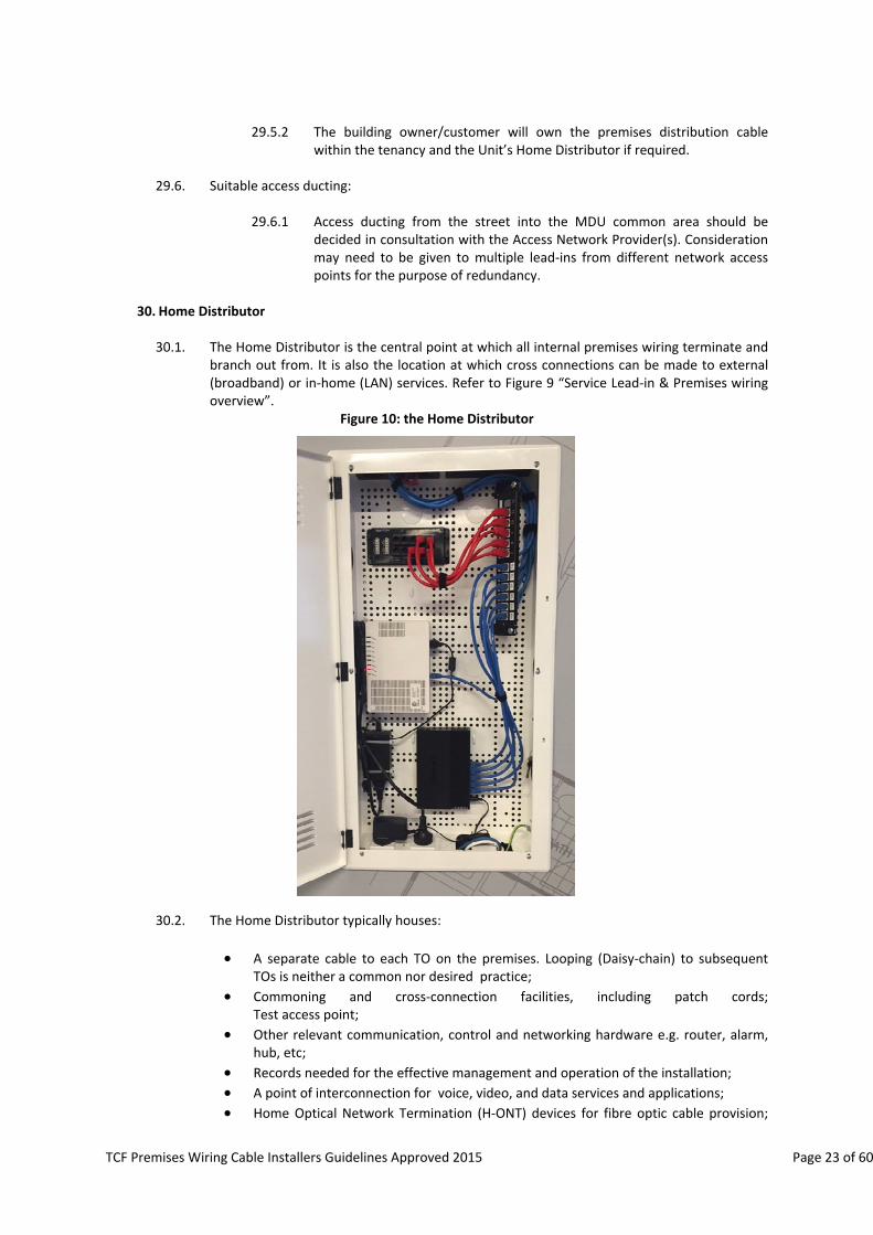
30.1. The Home Distributor is the central point at which all internal premises wiring terminate and branch out from. It is also the location at which cross connections can be made to external (broadband) or in‐home (LAN) services. Refer to Figure 9 “Service Lead‐in & Premises wiring overview”.
Figure 10: the Home Distributor
30.2. The Home Distributor typically houses:
A separate cable to each TO on the premises. Looping (Daisy‐chain) to subsequent TOs is neither a common nor desired practice;
Commoning and cross‐connection facilities, including patch cords; Test access point;
Other relevant communication, control and networking hardware e.g. router, alarm, hub, etc;
Records needed for the effective management and operation of the installation;
A point of interconnection for voice, video, and data services and applications;
Home Optical Network Termination (H‐ONT) devices for fibre optic cable provision;
TCF Premises Wiring Cable Installers Guidelines Approved 2015 Page 24 of 60
and
Power distribution facilities where Power Over Ethernet (POE) devices are used through the premises.
30.3. In the situation where the Home Distributor is of metal construction any WiFi device installed
inside the Home Distributor will have significantly reduced WiFi performance. It is recommended that any device supplying WiFi signal should not be installed within a metal Home Distributor.
30.4. The Home Distributor is essentially a cabinet, mounted in or on a wall, or a cupboard in which the cable termination hardware and other components are housed. Equipment within such a cupboard may be wall or rack mounted.
30.5. It is recommended that a Home Distributor be installed in all new homes and any existing
premises undergoing major refurbishment, and is ideally located on an inside wall immediately behind and above the ETP position. The location of the ETP should be discussed with the chosen Access Network Provider. Refer to section 27.
30.6. It is recommended that the top of the Home Distributor be installed no higher than 1.85m
from the ground/floor. 30.7. Home distributors installed in the wall cavity should be large enough to adequately store the
cable termination hardware and other components, at least 700mm (high) x 350mm (wide) x 80mm (deep). While stand alone or surface/wall mounted or Rack (19”) mounted distributors should be least 700mm high and 300mm deep. However, where practical it is recommended that a larger cabinet be installed to accommodate any future hardware and componentry.
30.8. It is envisaged that existing residential and SDU premises will transition, through a series of
stages, to a full Home Distributor over an extended period of time. The first stage may be as simple as installing a multi‐point faceplate from which traditional PSTN and new TP Cat6a cables radiate out from and to which modems, network hubs and gateways connect to deliver service. Refer to Appendix 1.
30.9. In existing homes, where access to the wall behind the ETP is not practical, the Home
Distributor should be mounted as close as possible to the ETP (on an inside wall), or arrangements made to shift the location of the ETP. Refer to section 27.
30.10. The Access Network Provider may have a maximum distance that the Home Distributor can be from the ETP before it is classified as a non‐standard install and therefore may incur additional installation charges. Consult with the Access Network Provider on the maximum internal distance between the ETP and the Home distributor.
30.11. In larger premises secondary Home Distributors may be installed to facilitate cable reticulation and service management. In MDU premises each unit must have its own building frame, which, in a MDU, connects to external network services and provides connections to outlets in an individual unit. SDU premises should have rack mount distributors.
30.12. Home Distributor general installation recommendations
30.12.1 The Home Distributor should not be located in an area subject to
condensation such as a bathroom, kitchen or laundry.
30.12.2 The Home Distributor must have adequate ventilation or forced cooling to allow for the continuous operation of any installed electrical equipment. For example venting in door or cabinet with adequate airflow.
30.12.3 An adequate level of lighting should be provided to maintain the Home
TCF Premises Wiring Cable Installers Guidelines Approved 2015 Page 25 of 60
Distributor and there should be at least 1m clear space in front of the Home Distributor to facilitate maintenance and user access.
30.12.4 All Home Distributors must allow for the isolation of premises wiring from
external networks. This enables simple tests to determine whether a fault or possible performance issue is in the external network or the premises.
30.12.5 Provision should be made for a connection point so that either an xDSL
splitter may be installed where DSL Broadband and traditional telephone (PSTN) services are delivered over the same copper pair, or a Gateway device installed where broadband and voice services are delivered via the xDSL (Naked DSL) circuit.
30.12.6 The Home Distributor shall include provision for connecting a "Line
Grabbing" alarm system between the NID and the Telephone Hub. A typical implementation is shown in Figure 3.
30.12.7 An installation should bear a label issued by a qualified installer that the
entire wiring system complies with the AS/NZ 15018.
30.12.8 The quality of the components installed will impact future performance and life expectancy of the system. It is strongly recommended that only components that have been independently certified by a recognised body, such as the Underwriter’s Laboratories (UL), be used.
30.13. Generic Cabling termination hardware within the Home Distributor
30.13.1 RJ45 patch panel hardware should be used. It is strongly recommended that
only patch panel hardware and patch cables supplied by recognised Generic Cabling manufacturers and independently certified by a recognised body such as the Underwriter’s Laboratories (UL) be used. Similarly, the recommendations of suppliers for the installation, testing, use and management of this hardware should be followed.
30.13.2 Only certified “multi use” Insulation Displacement Connectors (IDC) RJ45
sockets should be used.
30.13.3 Fibre optic sockets should contain SC/APC type connectors that are housed in a purpose built enclosure that incorporates a shutter that provides a high level of laser safety.
30.14. Cross‐connections
30.14.1 For consumers with little technical knowledge patch cords are a practical
approach to forming cross connections, as no special tooling is required and cross‐connections are easily carried out so long as connection points are clearly marked.
30.14.2 For long‐term reliability it is strongly recommended that RJ45 patch cables
be factory‐terminated and of such a length that there is plenty of flexibility for movement, but it is not necessary to coil up surplus within the Home Distributor.
30.14.3 While it may initially be cheaper to terminate appropriate short lengths of
cable “on‐site”, such connections can prove unreliable in the longer term. In particular, the use of solid conductor cable as patch cords often proves unreliable where the patch cords are subject to movement during the
TCF Premises Wiring Cable Installers Guidelines Approved 2015 Page 26 of 60
service life of the installation.
30.14.4 Flexible factory assembled patch cords should preferably be used to ensure that subsequent movement during re‐connection work will not result in failed connections.
30.14.5 Where cables or cords are “on‐site” terminated, it is important that the
correct type of plug and crimping tool is used. Plugs intended for use with flexible cords are not suitable for use on solid core cable, nor are those intended for solid core cable suitable for flexible cords.
30.14.6 Where a service lead is not terminated directly onto the Optical Network
Terminal (ONT) but to the fibre socket the connection will be with a SC/APC to SC/APC patch cord.
30.15. Hardware for other services within the Home Distributor
30.15.1 The Home Distributor may also house a router for home Local Area Network (LAN) operation, along with its power supply; television distribution hardware (coaxial cables, amplifier, splitter and power supply); infra‐red remote controls for the AV system; a security system or medical alarm connections.
30.15.2 There is no constraint on what hardware is fitted within the Home
Distributor as long as it facilitates ease of operation; the cabling should be installed in a tidy and uncluttered manner with adequate clearance between components to ensure electrical interference is minimised, and adequate cooling is provided.
31. Power supply
31.1. Services delivered to End Users using technologies other than the copper based PSTN may
rely on a power source being available at all times to sustain the delivery of voice services, and other solutions dependent on voice services, such as monitored and medical alarms.
31.2. It is recommended that an Uninterrupted Power Supply (UPS) device with surge protection is
installed to provide power backup during power outages, and ensure service continuity for telephones, alarm systems and other home mission critical services.
31.3. A UPS operates like a backup battery and typically lasts for one or two hours. The Service
Provider is the first point of contact for information on UPS installations, as it must comply with the overall solution provided.
32. Generic Cabling
32.1. An installation may make use of a range of technologies and practices, including:‐
32.1.1 Cat6a Twisted Pair (TP) cable is recommended and RJ45 connectors at the
equivalent standard, primarily for telephony and data, but also capable of supporting other services, such as audio and video, home control, etc;
32.1.2 To further future proof the premises fibre optic cable can be used instead of Cat6 cable. This may require the use of media convertors to provide services within the premises.
32.1.3 All internal coaxial cable within the home should be RG6 Tri‐shield or
better. This is used for television and high‐speed internet connections. RG6

TCF Premises Wiring Cable Installers Guidelines Approved 2015 Page 27 of 60
coaxial cable and “F” connectors for TV baseband applications, including free to air services (i.e. Terrestrial broadcast & pay TV)For satellite TV;
32.1.4 For MDU consideration should be given for the installation of a fibre‐optic
cable distribution system between the building frame and the secondary Home Distributor. This system should terminate in a common area with dedicated fibres to each unit, a minimum of two fibres per unit is recommended; and
32.1.5 Cabling to devices to provide Wireless services, such as WiFi and cordless
telephones.
32.2. A Generic Cabling system is a system that is designed to conform to a set of rules providing support for multiple applications, and is typically a system based on high performance coax and 4‐pair TP cable wired in a star wiring configuration.
32.3. The performance characteristics of TP cabling commonly used in residential and commercial
communications applications is expressed by its design or UTP Category (Cat) rating, the most common being:
Legacy < 2Mbps/sec telephone and control applications.
Cat3: performance to 16MHz to support 10Mbits/sec Ethernet networks.
Cat5e: performance to 100MHz to support 1Gbits/sec Ethernet networks over a distance of 100 metres. This allows for 90 metres of fixed cabling and an allowance of 10 metres for terminations and patch cords.
Cat6: performance to 250MHz to support 1Gbits/sec Ethernet, with a maximum allowed length of 100 meters. This consists of 90 meters of cabling plus and an allowance of 10 metres for terminations and patch cords.
Cat6a: performance to 500MHz to support 10Gbits/sec Ethernet with a maximum
allowed length of 100 metres. This consists of 90 meters of cabling with an allowance of 10 metres for patch cords and terminations.
32.4. Note: All cabling systems coax, fibre optic cable and Twisted Pair needs to be correctly
installed and maintained if prescribed performance levels are to be realised over the installation’s planned life.
32.5. Internal Generic Cabling
32.5.1 All cables, TO’s and hardware used in wiring a residential premises should
be compliant with the relevant industry standards and carry a recognised international independent assessment body of quality and safety e.g. Underwriters Laboratories (UL) or an equivalent New Zealand body.
32.5.2 Shielded Twisted Pair (STP)
a) Cable should be 4‐pair of Cat6a or higher performance for both residential
and commercial wiring, since this is now the recognised minimum industry standard. All such cable should have nominal 0.5mm diameter conductors and its sheath should bear an industry‐recognised certification mark and performance rating in accordance with international standards.
b) All cable runs should be continuous without joins.
TCF Premises Wiring Cable Installers Guidelines Approved 2015 Page 28 of 60
c) The entire cable run must be replaced if it is damaged in order to maintain performance.
32.6. MDU Fibre Optic Distribution Cable
32.6.1 Fibre‐optic distribution cabling within a MDU should be distribution type
with either sufficiently robust construction or sufficiently well protected to withstand physical damage. The fibre should conform to the Standard ITUT G.657A (Bend insensitive). This outer sheath should be of a Low Smoke Zero Halogen (LSZH) type.
32.6.2 These cables are excellent for indoor use. They do not provide the best
moisture and environmental protection and therefore are not recommended for outdoor applications.
32.7. Cable used for wiring outdoors should be purpose made “external” cable.
32.7.1 Typical outdoor Cat6a cables are either drycore water blocked (using water
blocking yarns) or Gel filled cables and have solid (not stranded) conductors. “Buried” and “self‐supporting aerial” types are available.
32.7.2 Whilst the use of UTP is typical standard practice, shielded twisted pair
(STP) types may be used in conjunction with shielded sockets and other shielded components where shielding is the basis of a commercial design and all components are installed by suitably trained and skilled staff.
32.8. Coaxial and Screened Cable
32.8.1 The delivery of radio frequencies over coaxial cable to most rooms of the
home should be done in a cost effective but technology neutral manner wherever possible. The coaxial cable wiring and connectors should be suitable for the delivery of all TV and data service providers using RF as the carrier. The current situation with different cabling methods and types force Retail Service Providers to re‐run appropriate coax to suit their products. A standard high quality coaxial system will avoid this.
32.8.2 Coaxial cabling for television and other radio frequency applications is
usually wired separately and independently of the telecom and data wiring within the premises. However, when any consideration is given to the cabling of new homes, the needs for reticulating free to air cable TV and satellite television should not be overlooked. With a modern home, the UTP and coaxial cabling can form an overall “integrated network” linking the various items of equipment, such that more or less any service is available at any location ‐ as long as suitable remote control facilities have also been provided.
32.8.3 With new construction the coaxial cables connect from the Home
Distributor, to every room where in‐house TV wiring is required whether it be cable TV, or a Satellite TV, or a closed circuit TV system. Consideration could be given to running two cables to each outlet position. This configuration forms a star topology. A multiport splitter is located at the centre of the star. At times an amplifier will be inserted between the video source and the multiport splitter to raise the signal level if several rooms are cabled. This will compensate for the signal losses caused by branch splitting.
32.8.4 It is recommended that specialist contractors be approached for more
TCF Premises Wiring Cable Installers Guidelines Approved 2015 Page 29 of 60
detailed information on the design of television distribution and remote control facilities.
32.8.5 It is recommended that dual RJ45 TO’s be provided at each proposed
television set location for either connecting the SKY decoder or, in future, the equipment needed for television delivery over Ethernet. The most convenient approach in a new home is to make use of a four‐way faceplate to house 2 x “F‐connector” and two RJ45’s. Refer to Figure 4 above. This is easily accomplished with the various makes and styles of modular faceplates used for electrical installations. These replaceable modules also avoid the need to replace a complete assembly should one or other parts fail in service.
32.8.6 High performance 4‐pair screened cable using screened TO’s and other
components rated at Cat6 or Cat7, may be used for television, video and audio distribution, as well as for data and telephony. Where these components are used, the relevant manufacturer’s recommendations are to be followed.
33. Ducting
33.1. Ducting involves the installation of purpose designed and installed pipes (ducts) to aid the reticulation and installation of new or replacement of wiring in and around a premises.
33.2. During the planning phase of any Generic Cabling installation serious consideration should be
given to the installation of ducts to areas that would prove difficult or impossible to install cables once the building is finished. The marginal cost of installing ducts may prove a valuable investment considering:
a) The financial and aesthetic costs of installing cables to difficult to reach locations
once the building is completed; b) The ability to replace cable as a result of damage or change of requirements;
c) The inconvenience costs to homeowners and occupiers of not being able to utilize
services in room and locations they wish;
d) The insulation, sound proofing and moisture blocking integrity of building systems (walls) may be compromised if improper cabling practices are used in a retrofit situation.
33.3. When deciding to use ducts, careful consideration should be given to the number of cables to
be installed in the duct and the impact that future installations may have on the capacity of those ducts. A duct in a straight run is considered to be at capacity when 50% occupied. If there are two bends up to 90° radius in the duct pull length, then it is considered to be at capacity when 40% occupied.
33.4. Consideration should be given to installing excess ducts or a larger bend radius to allow for future cabling. For example, the bending radius required for optical fibre cable is greater than that required for twisted pair cable.
33.5. Conduits, ducts and trunking may be made of plastic, aluminium or galvanized steel. (Ferrous metal construction will give superior protection from EMI, provided that continuity is maintained).
33.6. Mechanical continuity must be maintained through joints in metallic conduits, ducts and trunking. This enables electrical continuity to be maintained as the conduit, duct or trunking system must be earthed in accordance with AS/NZ3000.
TCF Premises Wiring Cable Installers Guidelines Approved 2015 Page 30 of 60
33.7. Conduits and trunking should have all sharp edges removed from their internal surfaces. (This
minimizes the risk of damage to the cable sheath).
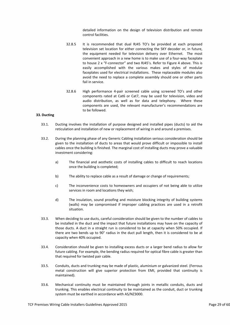
33.8. Conduit runs in indoor situations should contain draw boxes (see Figure 9) at distances of ≤30metres. If distances between draw boxes exceed 30 metres, a larger sized duct should be used for the runs. The draw boxes must be large enough to permit the minimum bending radius of the largest installed cable to be maintained. (These requirements are to allow for ease of installation. They also allow for drawing through additional cable at a later date and minimize the stress on the cables during the installation. Maintaining the minimum bend radius specified by the cable manufacturer is a mandatory requirement).
Figure 11: an Example of Draw Boxes
34. Telecommunications Outlet (TO)
34.1. Telecommunication Outlets are essentially “general purpose” and may support a range of services, depending on how they are connected at the Home Distributor. Each TO can provide a connection point for the transmission and/or reception of information, depending on the type of equipment connected to it.
34.2. The total number of TO’s that may be installed in any premises is not restricted. The
installation of TO’s on a lavish basis is encouraged as a way of meeting unplanned future requirements, and at a minimum, consideration should be given to having at least two TO’s a room to provide for more than one option for the placement of communication/television equipment.
34.3. The number of outlets recommended has been based on the following requirements at a typical TO location (e.g. Bedroom):
a) Two RJ45 outlets that can be used for either voice or data services. b) One “F” connector would be used for TV services.
34.4. It is recommended that two RJ45 sockets be installed at each TO location, with the following
regarded as the minimum number to be installed in any new home:
a) at least one set of two in every room normally used by the occupants on a daily basis (kitchen, lounge, rumpus room, study, etc, other than “wet rooms” such as bathrooms, shower rooms, or laundry);
b) at least one set of two in every room that is intended as a bedroom;
c) one set of four located within 1 metre of each television antenna outlet location;
TCF Premises Wiring Cable Installers Guidelines Approved 2015 Page 31 of 60
● Combining the four RJ45 TO’s with coaxial “F” connectors on the
same faceplate is recommended for maximum flexibility. ● For feeding ATA/Data back to the Home Distributor from the
RGW. ● With Power over Ethernet (POE) installed, these TO’s can also be
used to provide power to the associated equipment, whether it be telecommunications network‐related or quite separate items such as security cameras and building control devices. This avoids the need for every TO to be located close to a 230 V power outlet.
34.4.2 It must be stressed the above is regarded as the minimum provision of TO’s.
It is recommended that due regard be given to the likely needs of the consumer, especially in larger rooms, to avoid long equipment cords, and for those rooms where additional access points are likely to be needed at more than one location. For example, there may be two or more “likely locations” for the television set and/or personal computer in the main family rooms.
34.4.3 These TO’s may also include provision on the same faceplate for one or
more co‐axial connectors, antenna or audio connectors, or other Extra Low Voltage services.
34.5. Hardware Type
34.5.1 Only a certified cabling system should be connected to an Access Network Provider’s access network (Section 106 of the Telecommunications Act 2001).
34.5.2 Connecting to the Access Network Provider’s access network an installation
should bear a label issued by a qualified installer to show that the installation complies with the Access Network Provider’s requirements and with AS/NZS 15018.
34.5.3 The socket assemblies used in TO’s should meet Cat6a or higher
performance requirements and be marked with the relevant Category rating.
34.5.4 Any brand or model of RJ45 socket, whether assembled into individual
modules with associated IDC connectors, or made up complete with faceplates, may be used as long as such sockets comply with a recognised industry standard and are marked accordingly.
34.5.5 Standard “Keystone” format socket assemblies are recommended where
the installation is not wholly based on some proprietary socket system using other than keystone sockets.
34.5.6 The associated IDC connectors must be certified “multiple use” type.
34.5.7 Unshielded TO’s are regarded as standard practice, but shielded types may
be used in conjunction with shielded cable and other shielded components where this is the basis of a commercial design and installed by suitable skilled staff.
34.5.8 TO’s with “tool‐less” IDC terminations are recommended where it is likely

TCF Premises Wiring Cable Installers Guidelines Approved 2015 Page 32 of 60
that subsequent jackpoint installation work will be carried out by premises owners not having the appropriate special insertion tools.
34.6. Labelling and identification
34.6.1 All TO’s should be individually labelled, with the same identification at the
cable termination in the Home Distributor, so that both cable and TO termination can be clearly associated when connecting new services.
34.6.2 Many faceplates and TO modules do not provide an actual label holder and
it detracts from the overall appearance to mark the faceplates. It is recommended that either hardware with removable cover plates be used (e.g. HPM and PDL 600 series faceplates), so that markings can be made on the underlying switch plate; or that a simple convention be used to identify individual TO’s on a dual or multi‐way switch plate in association with a building layout plan. For example, numbering all TO’s from left to right or top to bottom in a consistent manner.
TCF Premises Wiring Cable Installers Guidelines Approved 2015 Page 33 of 60
J. INSTALLATION GUIDELINES 35. The objective of this section is to provide best practice recommendations and a set of minimal
requirements for premises wiring installations. 36. For the benefit of consumers, Cable Installers are urged to follow the recommendations provided in
this Document, when considering their customer’s telecommunication service requirements. 37. All recommendations and requirements provided in this document are generic, and neutral to any
specific vendor or hardware. Where specific vendor or product requirements exceed the requirements stated in this Document, the former should be met.
38. Safety Requirements
38.1. General
38.1.1 All Generic Cabling should be undertaken safely by the cable installer.. Safe electrical industry working practices should be followed, and full compliance with all relevant industry safety standards is required from the cable installers and other stakeholders.
38.1.2 Any potential hazards should be identified and mitigated prior to starting
each aspect of the work.
38.1.3 Special care should be employed where changes to existing installations involve work in dark ceilings, wall cavities and other areas containing power cables, gas and water pipes.
38.2. Hazardous Voltages
38.2.1 Under normal conditions no hazardous voltages are applied by an Access Network Provider to telecommunication lines. Nevertheless, it is possible for lines to become hazardous at any time from earth potential rise, power distribution system faults, lightning activity, or contact with power wiring within the premises owner’s own premises or equipment. The Installer should check for hazardous voltages before carrying out any work on premises wiring.
38.2.2 All the internal telecommunication wiring should be completed before
finally connecting to the incoming line.
38.2.3 IDCs should be used wherever possible throughout the telecommunication cabling installation. This is to prevent the consumer and installer from the direct contact with bare conductors and minimising a risk of shock from non‐hazardous network voltages, such as ringing. The reflexive action to a LV electrical shock can lead to adverse outcomes, such as person losing balance and falling etc.
38.2.4 To comply with AS/NZS 3000, any metal cabinets used for the Home
Distributor must be earthed and LV cabling should be enclosed in a separate compartment to that which houses the ELV or TNV cabling.
38.3. Under NO circumstances shall Low Voltage (LV e.g., 230 V) sockets, switches or modules be
mounted on the same faceplate as TNV or ELV components (voltage levels at which telecommunications and data services operate). The joint Australia/New Zealand Wiring Rules (AS/NZS 3000) require that all faceplates comply with AS/NZS 3112, clause 3.2 of which prohibits mixing of these voltage levels on the same faceplate.

TCF Premises Wiring Cable Installers Guidelines Approved 2015 Page 34 of 60
38.4. For home use, where small children are present, there is the possibility of a child inserting a
finger or a conductive object into an open socket. Although TNV3 (with typical voltages in 42.4V ‐ 90V) is not regarded as “hazardous”, the child could receive a shock when ringing voltage is applied to the outlet.
38.5. If no CPE is connected to the outlet located within children’s reach, it is recommended:
that the TO patch cord is removed at the Home Distributor; or
A shuttered socket is used in the TO; or
A “dummy” plug is inserted into the wall socket to close off the aperture.
39. Telecommunication Wiring Practices
39.1. Generic home telecommunication cabling uses the same components as commercial building cabling, which is designed to provide the required performance with cable runs of up to 90 metres.
39.2. Accepted industry practices should be complied with in order to maintain the
telecommunication cable performance. This includes the following:
39.2.1 Telecommunication Cable should not be deformed prior to, during, or following installation to maintain high frequency transmission performance characteristics.
39.2.2 During installation telecommunication cable should not be jerked or pulled
such that the tension exceeds 110 N (approx. 11 kg).
39.2.3 There should be no kinks or twists in the installed telecommunication cable.
39.2.4 Bend radius of the installed copper telecommunication cable should not be less than 4 times the cable diameter. Typically no sharper than 25mm. If installing fibre optic cable, refer to the manufacturers requirements for the bend radius specifications and if not specified then the minimum bend radius is 10 x the radius of the telecommunication cable as specified in the ITUT‐G.652D, or in the case of ITU‐T G.657A fibre 10mm.
39.2.5 Pairing should be maintained as close as possible to the wire terminations
(IDC connections); telecommunication cable sheath removal is to be limited to less than 12mm for Cat6a.
39.2.6 Telecommunication cable sheaths should not be crimped or distorted by
clipping, stapling or cable tying.
39.2.7 For new installations, even where only one line is initially required, a minimum of 4‐pair TP (Cat6a) and a draw wire should be run from Home Distributor to the Building Point of Entry (BPE) with at least 1m of slack at the BPE end.
39.2.8 An accessible telecommunication cable path should be provided between
BPE and the Home Distributor to allow for future addition of the telecommunication cables by the access network provider. Such cable path will cater for future installation of FTTP or an additional UTP or coaxial cables.
39.2.9 Should any part of the telecommunication cable path between BPE and the

TCF Premises Wiring Cable Installers Guidelines Approved 2015 Page 35 of 60
Home Distributor be not directly accessible for telecommunication cable addition, a duct or a plastic conduit should be provided as part of the initial installation. The minimum recommended duct diameter is 25mm. The duct should have a draw wire installed which should be secured and labelled at either end.
39.2.10 This document is primarily concerned with the telecommunication cabling
of new homes. As such, the telecommunication cabling is expected to be carried out at the pre‐lining stage of the building. While this makes for easy access to the framing for drilling access holes and running the cable, it does bring the risk of the telecommunication cables being damaged by other building operations or being obscured if no aperture is cut in the lining. This leads to the following recommendations:
a) To the maximum practicable extent, electrical and telecommunications
cabling should be left until the main framing has been completed and weather‐protected, and all water and/or gas piping is installed
b) All data cables installed inside the walls should be routed to the TO via
direct vertical line. Thus allowing the later addition of extra cabling to the same TO. Any holes drilled though timber framing during the initial installation should have a minimum diameter of 25mm.
c) As a general principle, TO’s should be mounted at the same levels as 230 V
power outlets so that any cabling obscured by subsequent wall lining operations can easily be retrieved. Marking the flush box locations on the floor (with the height of the flush box centreline above floor level also marked if it is not at the usual level) eases retrieval and ensures that the cabling is not overlooked if it is accidentally obscured by lining material;
d) UTP and coaxial cable should NOT be coiled up in the flush box, but be run
past the flush box without unnecessary bending, to be pulled back when it is time to make the terminations.
e) All cables should be clearly and uniquely labelled at both TO and Home
Distributor ends.
39.3. The following recommendations apply specifically to UTP, STP, coaxial and all optical fibre (glass or plastic) Generic Cabling in residential and SDU premises.
39.3.1 Cleanliness
a) All telecommunication cabling hardware should be kept clean during installation, avoiding contact with dirty hands, dust from building operations or other contamination likely to cause premature corrosion.
b) Following their termination, RJ 45 sockets should be protected from dust
entry, paint, plaster, etc, until building operations are completed. This can be achieved by protecting an outlet with a plastic cover or wrapping each individual RJ‐45 socket in a small plastic bag.
39.3.2 Particular attention should be given to the prevention and control of
moisture entering telecommunication cables through or along their sheaths, which is the dominant cause of wiring faults in typical New Zealand dwellings.
39.3.3 Moisture protection

TCF Premises Wiring Cable Installers Guidelines Approved 2015 Page 36 of 60
a) In order to prevent water transported on or within the sheath from
reaching the associated terminations and hardware, telecommunication cables should enter terminating hardware enclosures either:
i) from below the enclosure; or
ii) Only with a drip loop provided if it is not practicable to enter from
below the enclosure.
b) For surface mounting boxes, this requires telecommunication cable entry at a bottom corner of the rear. For flush mounting boxes, cable entry needs to be from the bottom.
Note: While it is obviously not intended, during the life of a building leaks in roofs or wall cladding, around windows, etc, as well as pipe leaks within the building, can lead to water coming into contact with telecommunication cabling. In some cases, the telecommunication cable sheath may absorb moisture or provide a path along which it can travel into the TO and result in service failure due to corrosion. This has proved to be a significant cause of service outages in New Zealand’s generally damp climate. This problem is likely to be more serious with generic cabling because of the closer pin spacing in RJ45 sockets and the unprotected design of some TO’s that are available, especially where high frequencies are used for enhanced applications and service degradation rather than complete failure could occur.
39.3.4 One dedicated cable, clearly labelled at both ends, should be run from the
Home Distributor to each TO.
39.3.5 Joints (or “splices”) and tee connections should NOT be made within these telecommunication cable runs. However, it is permitted to terminate a telecommunication cable at either end with an RJ45 plug designed for connecting solid conductors.
39.3.6 Once installed, the location of TO’s is relatively inflexible. Moving an
existing jackpoint or providing an additional one, would almost invariably require a new telecommunication cable run back to the distribution point, because joints are not permitted.
39.3.7 All conductors of cables from TO’s should be terminated on either purpose‐
designed terminations or RJ45 plugs within the Home Distributor.
39.3.8 At least 300mm of telecommunication cable should be left slack in the wall cavity at both ends of a run following its termination. This should be passed back into the wall cavity to form a “drip loop” such that should any water contact the cable it will not run into the TO.
39.3.9 All 8 conductors of each cable should be terminated, ensuring that pairing is
maintained and wire mapping is in accordance with Section L: Installation Testing.
39.4. Segregation of Services
39.4.1 To avoid the risk of electrical hazard and noise caused by induction,
Telecommunications cables must be installed with a permanent separation of at least 50mm from mains power cables in all locations, except where the

TCF Premises Wiring Cable Installers Guidelines Approved 2015 Page 37 of 60
cables are separated by a rigid barrier, an AS/NZ3000 requirement.
a) Either side of the stud is the preferred method of achieving this separation. b) To minimise the risk of electrical interference from mains and switching
transients or interference generated by appliances, the recommended spacing is at least 300mm wherever it is practicable to do so.
39.4.2 TO’s and associated hardware should not be fitted closer than a horizontal
distance of 200mm from any fitting on which mains voltage cables are terminated, unless separated by a rigidly fixed barrier. However, there are further restrictions on the use of such barriers, as detailed in clause 38.
39.4.3 Complying barriers include wall linings, full depth framing in walls and
substantially enclosed mounting boxes. Electrical flush mounting brackets and open type flush boxes are NOT substantially enclosed in the above context. Without a barrier, the minimum 200mm horizontal separation applies to both sides of a wall unless the wall cavity exceeds 200mm depth.
39.4.4 To minimise the risk of noise by induction, telecommunications cable
should not be run closely spaced and parallel to wiring of other services. Where it is not practicable to completely avoid such parallel runs, any length where spacing is close to the minimum of 50mm, should not exceed 3m.
39.4.5 Telecommunications cables should cross LV cable at right angles,
maintaining the necessary separation by means of securing or by an insulated barrier.
39.5. Telecommunication Wiring under Floors
39.5.1 Telecommunication cables should be run clear of potentially wet surfaces,
such as the ground, along areas at the bottom of outside walls, bathrooms, showers, water tanks, laundries, and any other areas where unintended water leakage or dampness may occur; unless the cable is specifically rated for this purpose.
39.5.2 Connections to telecommunication cables should be made only in readily
accessible locations and using purpose‐designed terminating hardware.
39.5.3 The telecommunication cable should be secured at changes of direction and at intervals sufficient to prevent undue sag and potential contact with subsequent groundwork or snagging during other under‐floor operations.
39.5.4 Closely spaced clipping along timber should be avoided, unless this is
necessary for appearance purposes when the telecommunication cable is exposed to regular view.
39.5.5 Telecommunication cables should be secured with plastic saddles not by
clipping or stapling to avoid metallic short circuits for compression of cable.
39.5.6 Large telecommunication cable looms should be cable tied to a centenary wire or cable tray.. Another widely used method of telecommunication cable management is staple‐tying.
TCF Premises Wiring Cable Installers Guidelines Approved 2015 Page 38 of 60
39.6. Telecommunication Wiring above Ceilings and Walls
39.6.1 Telecommunication cables in ceilings and wall cavities should be segregated from power cables in accordance with clause 39.4.
39.6.2 Telecommunication cables in ceilings should be routed clear of areas where
potential damage may occur, such as areas used for storage, or around chimneys, flues, heating ducts, water tanks and plumbing.
39.6.3 Telecommunication cables should be routed along timber above the ceiling
joists wherever possible, to avoid exposure to any water retained by the thermal insulation used between the joists.
39.6.4 Telecommunication cables above cathedral ceilings and horizontal runs in
outside wall cavities should be avoided wherever it is practicable to do so.
39.6.5 In any roof areas where the height exceeds 600mm, telecommunication cable should be laid below or clear of surfaces likely to be stood or knelt on, and should be secured to prevent snagging during later operations.
39.6.6 Telecommunication cables should not be clipped or otherwise secured in
wall cavities or other inaccessible areas.
39.7. Telecommunication Wiring Within a Concrete Wall
39.7.1 Telecommunication cables should not be laid directly into concrete walls, floors or ceilings. Where it is necessary for telecommunication cabling to pass through or be carried within a concrete structure, it should be housed within a rigid plastic pipe. Any such pipes should be laid on a slope such that any water running down external walls does not run into the building.
39.8. Telecommunication Cables Surface Mount on a Concrete Wall
39.8.1 The installation should facilitate later removal and replacement of the
telecommunication cables, if required. Draw‐wires should be installed in all ducts. The duct should be direct strait run. Any given length of duct should not have more than two bends or elbows.
39.8.2 Internal building telecommunication cable should not make direct contact
with concrete surfaces, particularly those of outside walls and ground retaining walls. Where exposed surface wiring cannot be avoided, separation from the concrete should be provided by enclosing the telecommunication cable in conduit or trunking, or by securing it to a timber batten with plastic saddles, not by clipping.
39.9. Surface Telecommunication Wiring
39.9.1 As a matter of good trade practice, surface wiring should be limited to
those few situations where there is no other option. The premises owner’s requirements should be included in building plans, and there should be little need for surface wiring.
39.9.2 In particular, surface wiring should be avoided in areas subject to potential
damage, including within 50mm of floors. Wherever possible, surface telecommunication cables should be protected from inadvertent physical damage by running them along the edges of skirting boards, scotia’s, architraves, or window and door frames.

TCF Premises Wiring Cable Installers Guidelines Approved 2015 Page 39 of 60
39.9.3 Any surface telecommunication wiring should be enclosed in a plastic duct
or capping with a recommended minimum size of 16mm x 25mm.
39.10. Telecommunications Wiring Between Buildings on Same Site
39.10.1 Where the telecommunication cable can be run entirely within a fully enclosed access‐way, it is deemed to be inside wiring.
39.10.2 Inside telecommunication cable may be run in conduit only where the cable
run is relatively short, above ground, sheltered from weather, and the conduit can be supported over the full distance on a convenient surface. Such installation should provide for later removal and replacement of the telecommunication cable, if required.
39.10.3 External telecommunication cable, should be used in above‐ground
locations exposed to weather, and should be attached to a structural surface or adequately supported by a self contained or separate bearer wire. The route should be clear of potential hazards and potential damage. Any poles used should adequately support a ladder to facilitate maintenance. To facilitate later removal and replacement of the telecommunication cable, if required, external telecommunication cable used for underground runs should be installed in a buried conduit which extends at least 300mm above the floor within an indoor location at each end.
39.11. Wiring to Equipment Exposed to the Weather
39.11.1 Where equipment and its associated telecommunication cabling and wiring
are exposed to the weather, all such components should be of a design suitable for this purpose.
39.11.2 Standard TO’s should not be located outdoors unless housed in industry
standard housings of the appropriate IP rating.
39.11.3 All elements of a data cable system exposed to the direct sunlight should be UV rated.
40. Cross‐connections and Commoning of TO’s for traditional analogue Telephone service
40.1. For telephony and voice‐band data services, the Home Distributor will usually incorporate
some form of commoning hardware to allow several TO’s to access the line concerned. There is no limit on the number of TO’s that may be connected to the same line.
Note: that the total number of Customer Premises Equipment (CPE) items which will operate correctly on a single analogue line is limited by the sum of the Ringing Numbers (RN) assigned to each CPE item connected to that line. Reliable ringing detection is achieved by ensuring the sum of the individual CPE “RN’ does not exceed five.
41. Connection of Broadband services
41.1. Connecting xDSL
41.1.1 With a Home Distributor and star wiring throughout the premises, the
Home Distributor should be used to house an xDSL splitter such that:
a) Any TO can be used to connect the xDSL modem; or preferably;
TCF Premises Wiring Cable Installers Guidelines Approved 2015 Page 40 of 60
b) The Home Distributor houses a modem with an integral router or the
modem and a separate multi‐port router, such that any TO’s can be used to connect PC’s and other equipment with an Ethernet interface;
c) Where a central xDSL splitter is mounted within the Premises Owner’s
premises, it should be of a network access provider approved type and should be connected on the network side of all other premises cabling, including line‐grabbing devices; and
d) Refer to Appendix 1 regarding xDSL interference specifications.
41.2. Connecting Fibre to the Premises (FTTP)
41.2.1 Given that the high speed broadband services are likely to be delivered to premises via a fibre optic cable, the home distributor need to cater for this type of installation.
41.2.2 The Home Distributor enclosure should be of sufficient size to be able to
accommodate an incoming duct with fibre cable and connector. It should also be of sufficient size to be able to accommodate a standard size Home‐Optical Termination Unit (H‐ONT). For further information please refer to section 30 on the Home Distributor.
41.2.3 The Home Distributor should be located as close as possible to the point
where incoming communications cabling enters the building. This is to minimise the amount of work and costs associated with an addition of the new services, such as FTTP based broadband.
42. Mounting Hardware
42.1. Where the TO is not designed to provide a reasonable level of protection against dust and
dirt within the wall cavity, boxes used for mounting TO’s and other terminating hardware should preferably be of substantially enclosed construction.
42.2. The sides, top and bottom of surface mounting type boxes should be continuous with
provision for cable entry at the lower rear.
42.3. The sides, rear and top of flush mounting types should preferably be continuous except for small holes, and the bottom should contain a cable entry hole not exceeding 30mm diameter
42.4. TO mounting hardware should be securely fixed in position. If not screwed to timber
framing, it should be rigidly fixed to wallboard using suitable fasteners.
43. Faceplates and socket orientation
43.1. Standard 230 V style rectangular faceplates matching those of the other electrical fittings in the home are recommended for aesthetic reasons. Those providing for separate modules to be fitted facilitate later replacement of any faulty or damaged modules without replacement of the complete assembly.
43.2. Faceplates may be installed “horizontally” (landscape) or “vertically” (portrait), but in all
cases the RJ45 socket should be oriented such that the plug latch will be on the underside. This ensures that the contact springs are at the top of the socket and less susceptible to dust or dirt settling on them.
43.3. Dual RJ45 TO's should be installed as the standard provision at each location. A larger
TCF Premises Wiring Cable Installers Guidelines Approved 2015 Page 41 of 60
capacity (four way or six way) modular faceplate allows for the fitting of 2 coaxial "F" connectors at any locations where a television set is likely to be used. Where the main television device is located provision should be made for 4 coaxial "F" connectors. Consideration must be given to multiple extra RJ45 outlets at the main TV position.
44. Copper Cable termination
44.1. Wires should be terminated on TO’s, cables, commoning and cross‐connect facilities only
with the correct purpose‐designed tool for the hardware concerned. IDC terminations should be used wherever possible.
44.2. All four pairs are to be correctly terminated; the wires of a pair should be kept together and
should be untwisted to the minimum practicable extent consistent with sufficient length for terminating them.
44.3. The following requirements apply to wiring terminations in insulation displacement
connectors:
44.3.1 Only strip as much sheath from the cable as is required to terminate the paired conductors (maximum 25mm), leaving the sheath intact as close as practicable to the actual terminations.
44.3.2 Insulated wires should be inserted into the slots with the insulation
undamaged in the vicinity of the actual connection.
44.3.3 They should be inserted individually from the correct direction, specified by the hardware manufacturer.
44.3.4 No attempt should be made to terminate wires of types other than those
which are specified for telecommunications wiring.
45. Fibre Termination
45.1. The Access Network Provider’s fibre may be terminated in a variety of methods depending on the cable and terminating practices of the Access Network Provider, namely terminated onto a termination point or terminated in a flexible fibre pigtail that can be plugged directly into the ONT. Provision should be provided for both methods of termination.
45.2. The Access Network Provider may provide a standard flexible cable or a high bend radius
cable from the home distributor to the ETP. The Home Distributor shall be laid out to accommodate a standard flexible cable with the larger bending radius.
45.3. A termination or distribution frame, suitable for the insertion of a minimum of two SC/APC
adapters, shall be provided. MDUs may require additional adapters and the number required should be discussed with the Access Network Provider.
45.4. The fibre adapters should be located so that when the external cable is installed, the
connector does not face upwards in order to minimise dust collection within the adapter and it shall not face outwards from the cabinet to prevent optical injury to those working on the cabinet. It is desirable to use adapters with inbuilt shutters to prevent optical injuries.
45.5. MDUs may require a lockable fibre distribution frame to prevent tampering of the external
fibre cable terminations. The Access Network Provider can provide further guidance of their requirements and they would hold the keys to the lockable frame (splice tray).
45.6. Provision for Splice trays shall be provided to enable the lead‐in cable to be terminated onto
a connector with a pigtail. A minimum of two splices is required for a SDU. The number of

TCF Premises Wiring Cable Installers Guidelines Approved 2015 Page 42 of 60
splices for a MDU will depend on the size of the lead‐in cable.
46. Wire mapping
46.1. There are two standard pin‐out options available, commonly referred to as “568A” and “568B”. The 568A option is the preferred option in Australia and New Zealand. This option should be used unless there is some specific reason why this is not practicable. Premises Owners should exercise caution when purchasing equipment (CPE) particularly from international sources as it may be wired to the 568B standard and therefore result in an incompatibility issue.
Figure 12: RJ45 Contact Spring Numbering
46.2. Note that many RJ45’s will show both options usually marked simply as “A” and “B”, with the relevant colours shown against terminals and no apparent references to the actual pins connected. The wire to pin allocation for 568A is shown in Table 1.
Table 1: Pin‐out Arrangement for the 568A Wiring Option
Pair Number Insulation Colours Abbreviations TO Pin Connection
Pair 1 White – Blue
Blue
WH – BL
BL
5
4
Pair 2 White – Orange
Orange
WH – OR
OR
3
6
Pair 3 White – Green
Green
WH – GR
GR
1
2
Pair 4 White – Brown
Brown
WH – BR
BR
7
8
TCF Premises Wiring Cable Installers Guidelines Approved 2015 Page 43 of 60
46.3. Whether the 568A or 568B option is used, the same option should apply throughout the
installation. During later cabling additions, the installer should check the existing wiring standard at the patch‐panel before any additional TO’s are terminated.
46.4. To avoid problems when additions are made, where the 568B option is used, this should be
clearly marked on the Home Distributor and in any user instructions or cable records.
47. CPE Connection to Copper Wire Network/Service Provider lines 47.1. Connection Options
47.1.1 Almost all telephones and related CPE now in service and new equipment
being offered for sale uses the 6‐way plug to BS 6312 adopted by Spark in 1983.
47.1.2 Where cabling is installed, it will generally be necessary to either use a
suitable adapter to connect such equipment to the RJ45 TO’s or have the line cords of CPE concerned re‐terminated with RJ45 plugs. This decision is left to the Premises Owner.
47.1.3 Where any older 3‐wire connected telephones are still in use, these will
require a “mastering” adapter with integral 1 microfarad capacitor to provide their ringing function.
47.1.4 All CPE must be approved by service or network providers before being
connected to that provider’s network.
48. Earthing
48.1. There is no provision for an earth connection to CPE via TO’s. CPE is deliberately isolated from earth as a safety measure.
49. Earthquake Protection
49.1. In order for the premises cabling to be used for lifeline service, such as (e.g. calling
emergency services) after an earthquake, the installation should be built to earthquake resistant standards.
49.2. Equipment, particularly within the Home distributor shall be restrained so that it does not
move and damage itself or adjacent equipment.
49.3. Power packs that are plugged into 230V outlets shall be secured so that they do not all out during the earthquake movement.
TCF Premises Wiring Cable Installers Guidelines Approved 2015 Page 44 of 60
K. INSTALLATION TESTING 50. The objective of this section is to provide guidelines on recommended testing requirements that
should be undertaken during the installation and commissioning of the Generic Cabling installation. 51. Additionally to provide guidance to the premises owner as to what test certification and compliance
documents they should expect to receive, to ensure the installation is fit for purpose. 52. Cable Installer’s obligations
52.1. Before handing any new or altered wiring installation work over to the premises owner, such work must be thoroughly tested to ensure that all wiring is correctly terminated in accordance with the type of jackpoint and termination hardware used. Pair integrity should be maintained. Any defective telecommunication cables should be replaced and termination faults remedied before handover to the premises owner.
52.2. The installer should ensure conformance to the following:
visual examination of the telecommunication cabling;
verification testing of the telecommunication cabling;
qualification testing of the telecommunication cabling; and
producing a report of results.
52.3. Where problems arise, the installer should ensure that all necessary remedial action is taken.
Note: The Consumer Guarantees Act 1993 applies ensuring that the installation is suitable for its intended purpose.
53. Damage
53.1. Telecommunications cabling (e.g., voice, data, video, security, audio, control) can be damaged during the construction phases of framing, gib board installation, and even during the cladding of the exterior. Many of these damaging faults result from causes such as nails and staples penetrating the cable, severe kinks in the cable where the cable was pulled through a drilled hole in a stud or joist, or a cable tear where the cable sheath and conductors are damaged from pulling the cable.
54. Visual Inspection
54.1. A visual inspection of each cable run should be made after the cable has been installed, but prior to installation of insulation and gib board.
54.2. This visual inspection may include but is not limited to:
obvious damage to cable (condition and workmanship);
separation from Electro Magnetic Current (EMC) i.e. power and radio sources of interference;
incorrect bend radii; and
noticeable excessive cable length.
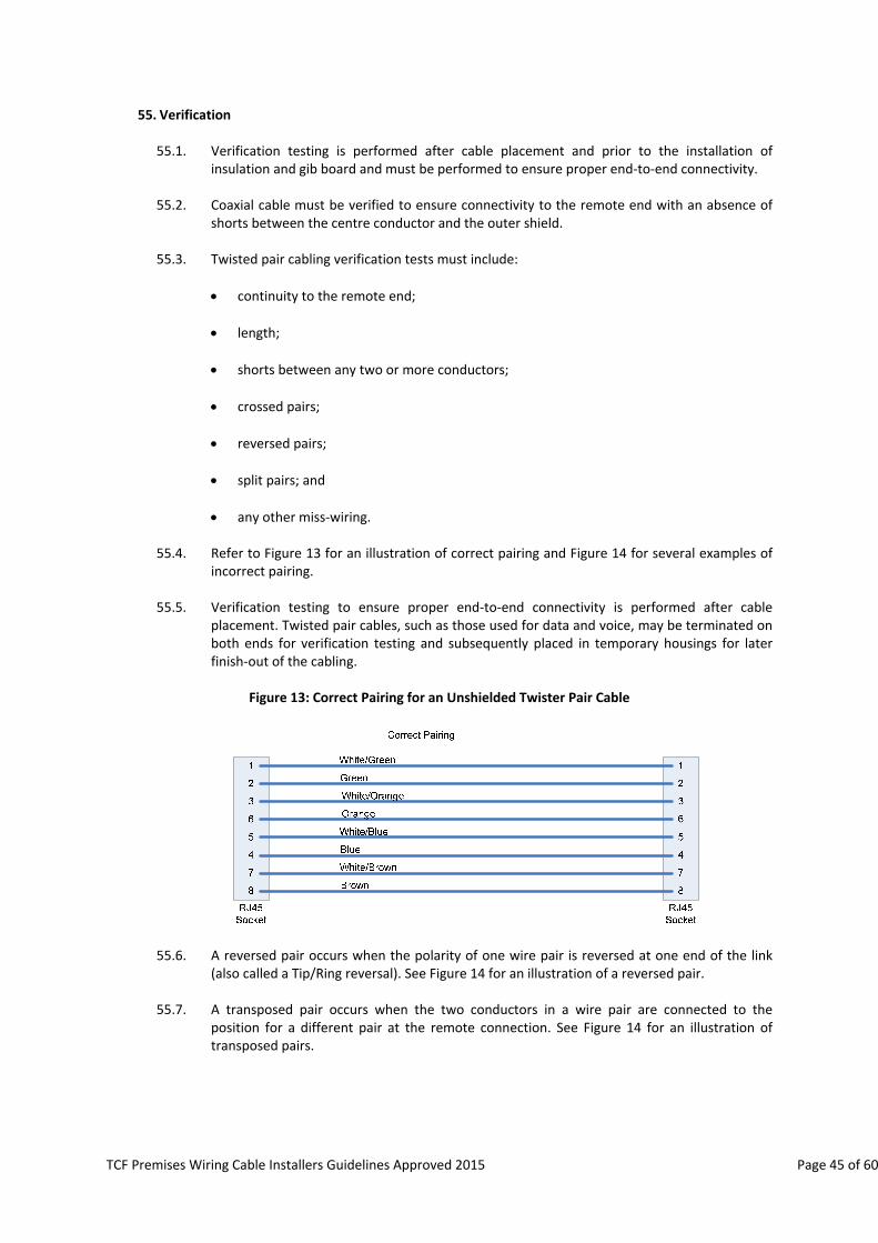
TCF Premises Wiring Cable Installers Guidelines Approved 2015 Page 45 of 60
55. Verification
55.1. Verification testing is performed after cable placement and prior to the installation of insulation and gib board and must be performed to ensure proper end‐to‐end connectivity.
55.2. Coaxial cable must be verified to ensure connectivity to the remote end with an absence of
shorts between the centre conductor and the outer shield.
55.3. Twisted pair cabling verification tests must include:
continuity to the remote end;
length;
shorts between any two or more conductors;
crossed pairs;
reversed pairs;
split pairs; and
any other miss‐wiring.
55.4. Refer to Figure 13 for an illustration of correct pairing and Figure 14 for several examples of incorrect pairing.
55.5. Verification testing to ensure proper end‐to‐end connectivity is performed after cable
placement. Twisted pair cables, such as those used for data and voice, may be terminated on both ends for verification testing and subsequently placed in temporary housings for later finish‐out of the cabling.
Figure 13: Correct Pairing for an Unshielded Twister Pair Cable
55.6. A reversed pair occurs when the polarity of one wire pair is reversed at one end of the link
(also called a Tip/Ring reversal). See Figure 14 for an illustration of a reversed pair. 55.7. A transposed pair occurs when the two conductors in a wire pair are connected to the
position for a different pair at the remote connection. See Figure 14 for an illustration of transposed pairs.
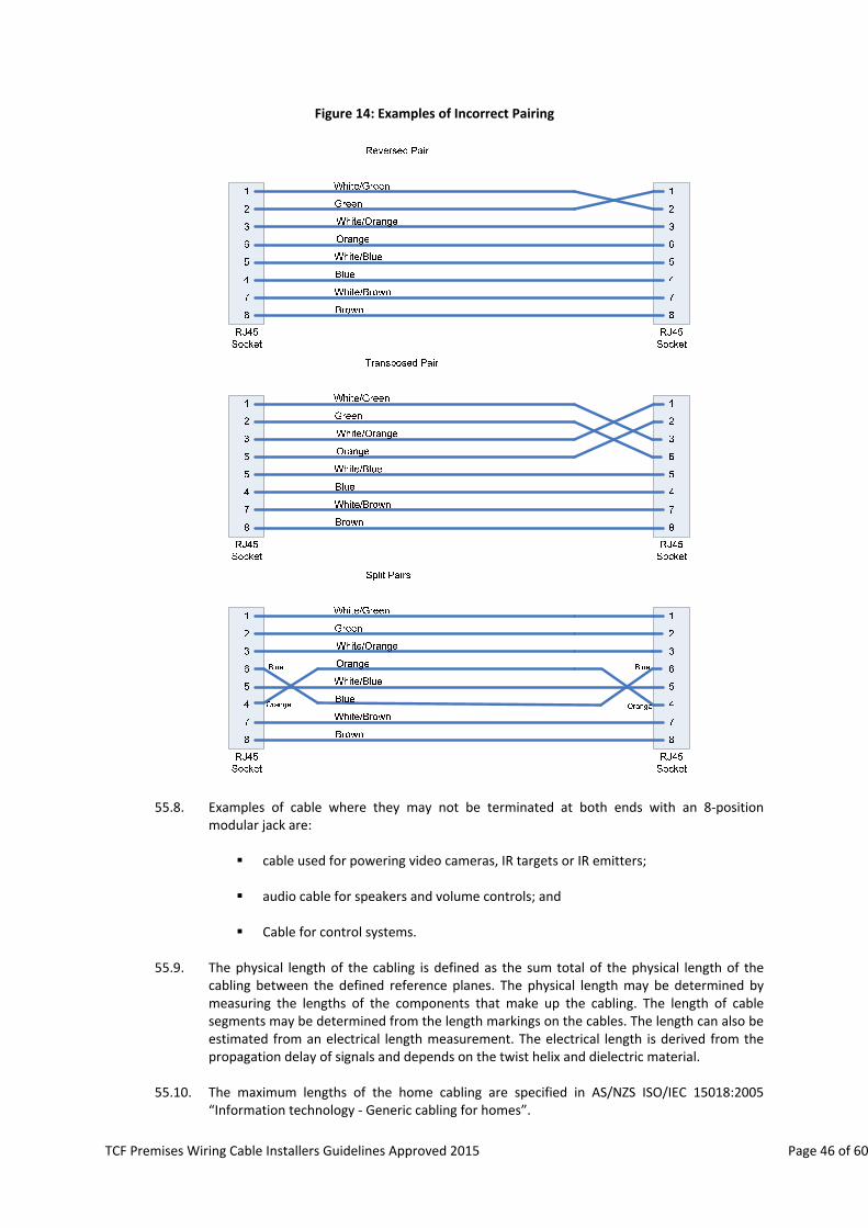
TCF Premises Wiring Cable Installers Guidelines Approved 2015 Page 46 of 60
Figure 14: Examples of Incorrect Pairing
55.8. Examples of cable where they may not be terminated at both ends with an 8‐position
modular jack are:
cable used for powering video cameras, IR targets or IR emitters; audio cable for speakers and volume controls; and
Cable for control systems.
55.9. The physical length of the cabling is defined as the sum total of the physical length of the
cabling between the defined reference planes. The physical length may be determined by measuring the lengths of the components that make up the cabling. The length of cable segments may be determined from the length markings on the cables. The length can also be estimated from an electrical length measurement. The electrical length is derived from the propagation delay of signals and depends on the twist helix and dielectric material.
55.10. The maximum lengths of the home cabling are specified in AS/NZS ISO/IEC 15018:2005
“Information technology ‐ Generic cabling for homes”.
TCF Premises Wiring Cable Installers Guidelines Approved 2015 Page 47 of 60
56. Qualification Testing
56.1. Qualification testing should be carried out by the Cable Installer to determine whether the installation is fit for purpose and will support certain network technologies (e.g., 1000BASE‐T, 100BASE‐T, FireWire). Qualification testing provides confidence to the premises owner that specific applications will work. For example, two cabling runs (cable A and cable B) pass the verification test. A qualification test may show that cable A is only capable of supporting 10BASE‐T, while cable B is able to support Gigabit Ethernet.
56.2. The qualification tests must be summarized within a documented report generated by the
test instrument. A copy of the test results summary must be provided to the premises owner and/or tenant of the home as well as placed in the distribution centre.
57. Qualification Test Instruments
57.1. Qualification test instruments must be capable of performing verification testing (wire
mapping and connectivity) and qualification tests. 57.2. Field test measurements of installed home telecommunication cabling designed in
accordance with this document to support AS/NZS ISO/IEC 15018 should be performed as follows:
57.3. Wire mapping
57.3.1 A conductor map test is intended to verify correct pin termination of the 8‐
pin connectors at each end of twisted pair cabling and to check for installation connectivity errors. For each of the conductors in the telecommunication cable, and the screen(s), if any, the conductor map indicates:
a) continuity to the remote end; b) shorts between any two or more conductors/screen(s); c) transposed pairs; d) reversed pairs; e) split pairs; and f) any other connection errors.
57.3.2 Correct connectivity of telecommunications outlet/connectors is defined in
AS/NZS ISO/IEC 15018 (or equivalent), and is illustrated in Figure 13 (for four pair cables).
57.3.3 A reversed pair occurs when the polarity of one wire pair is reversed at one
end of the link (also called a Tip/Ring reversal). See Figure 14 for an illustration of a reversed pair.
57.3.4 A transposed pair occurs when the two conductors in a wire pair are
connected to the position for a different pair at the remote connection. See Figure 14 for an illustration of transposed pairs. Transposed pairs are sometimes referred to as crossed pairs.
57.3.5 Split pairs occur when pin‐to‐pin continuity is maintained but physical pairs
are separated. See Figure 14 for an illustration of split pairs.

TCF Premises Wiring Cable Installers Guidelines Approved 2015 Page 48 of 60
57.4. Qualification Test
57.4.1 Qualification tests analyse the network capability of telecommunication
cable by injecting signals and analysing their responses, including any interfering signals that are within its field of influence. The resulting analyses of these signals are then compared to known network technology requirements. The result can then be saved to the test instrument for producing documentation.
57.4.2 The field test equipment must be capable of reporting minimum summary
information for each cable run:
a) Cable ID; b) Date; c) Time; d) Length; e) Wiremap; f) Network technologies supported; g) Network technologies unsupported; h) Test instrument serial number; and i) Test instrument use.
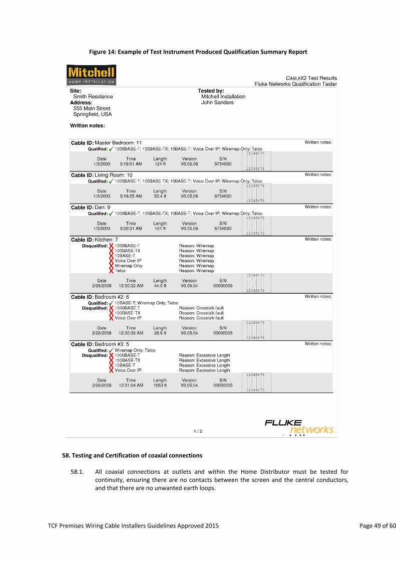
TCF Premises Wiring Cable Installers Guidelines Approved 2015 Page 49 of 60
Figure 14: Example of Test Instrument Produced Qualification Summary Report
58. Testing and Certification of coaxial connections
58.1. All coaxial connections at outlets and within the Home Distributor must be tested for
continuity, ensuring there are no contacts between the screen and the central conductors, and that there are no unwanted earth loops.

TCF Premises Wiring Cable Installers Guidelines Approved 2015 Page 50 of 60
L. RECORDS MANAGEMENT
59. Generic Cabling Management
59.1. The installer may provide written advice to the premises owner on the basic management and operation of the Generic Cabling system. Such advice may be in the form of standard information published by the supplier of the cabling hardware or a premises owner‐specific document drawn up by the installer.
59.2. In particular, the user information should include:
59.2.1 a simple means of indicating the terminations within the Home Distributor
that correspond with each TO and clearly explain the means of making and recording the necessary cross‐connections; and
59.2.2 a clear explanation of how to use the disconnect house wiring from the
network and test house wiring functions.
59.3. The overall aim is that information and installation records prepared by the installer should explain to the premises owner how the system is set up and have a reasonable chance of being able to make cross‐connections when service “add, moves or changes” are needed.
59.4. Unless it is completely clear from inspection of the Home Distributor cabling and cross‐
connections, all Generic Cabling installations should be provided with clear installation instructions and facilities for recording the service connected to each jackpoint.
Note: The use of appropriate colour coding schemes and clear labelling of all components may be such as to obviate the need for a “paper record”, especially where the installation is small and few services are connected. The aim is to ensure that the information available is such that an average premises owner or service person will not have undue difficulty in determining what service is connected to any TO.

TCF Premises Wiring Cable Installers Guidelines Approved 2015 Page 51 of 60
Table 2: Example of Test Instrument Produced Qualification Summary Report
TO/HD DESIGNATION Connected to Service Comments
1 Line 2 telephone Family phone line
2
3 Line 1 telephone Home business line
4 Colour Laser printer
5 Router Port 1 Home LAN
6 xDSL Modem Broadband
7
8
9 Router Port 2 Home LAN
10
11
12
13
14
15
16 Line 2 telephone DECT base station
17
18
19
20
21
22
23
24
25 Line 2 telephone Family phone line
26 Router Port 3 Home LAN
27
28 Router Port 4 Home LAN
29
30
Coaxial 1 SKY antenna
Coaxial 2 Free to Air antenna
Coaxial 3 Infra‐red target for Video
Coaxial 4 VCR AV input
Coaxial 5 Bedroom TV
Coaxial 6
Coaxial 7 Front security camera
Coaxial 8 Rear security camera
Coaxial 9
Coaxial 10
59.5. A typical example of a Generic Cable record is where every TO telecommunication cable is
terminated on an RJ45 socket using the same designation within the Home Distributor. Coaxial outlets and locations are not defined and are shown only as “reminders”.

TCF Premises Wiring Cable Installers Guidelines Approved 2015 Page 52 of 60
60. Installation records
60.1. The installer should provide a basic record system relevant to the cabling and hardware installed in a format that the premises owner and subsequent service staff may annotate changes to the records (e.g. an outlet is used for another purpose).
60.2. The actual format of this record is left to the installer to agree with the premises owner.
However, it is suggested that this be based on a floor plan of the premises showing TO locations and identification details for each TO.
Note: With a simple numbering system used for the TO’s, these numbers should align with the termination numbers used at the Home Distributor end of the TO cables. Any record is then a simple case of stating what services are connected at each TO and showing any TO that is not in current use. This avoids the risk of premises owners thinking a TO is faulty when it is simply not connected at the TO.
60.3. An example of a simple cable record is shown above. Note that this record can become far
more complicated if the TO and Home Distributor ends have different identification numbers or designations.
61. Compliance Statement Documentation
61.1. Following testing and any necessary remedial action, the installer should provide a written
statement of compliance to the premises owner showing the extent of the testing carried out, the name and associated company of the person conducting those tests and the date on which the installation was compliant.
Note: It is recommended that this statement of compliance be housed within the Home Distributor cabinet.
M. SPECIAL SITUATIONS
61.2. Non‐telecommunication systems such as gate entry systems must be connected on the premises owner’s side of the network demarcation point. It is not permissible to divert and use the network provider’s lead‐in cable between the network cable terminal on the road frontage and the network demarcation point at the building entry point, for this purpose
Note: Where a gate entry system is to be installed for a new building, especially if it has a long driveway, the recommended approach is to co‐ordinate the lead‐in and gate entry cable installation with other building services work. This allows the several services concerned to share the lead‐in cable trench, which is paid for by the premises owner. The gate control installation contractor can then run the necessary control and communication wiring before the trench is closed.
61.3. Fixed wiring of CPE is limited to non‐telecommunication systems such as security and alarm
devices whose primary purpose would be defeated, if connected at any general purpose TO. Line grabbing CPE, such as security diallers, should be directly connected at the Home Distributor. Such connections may be via jumpers, patch cords or direct hard‐wired connections.
61.4. Connection of alarm wiring should be terminated and connected in the Home Distributor. Such connections maybe via jumpers, patch cords or direct hard‐wire connections.
61.5. Where the building has a monitored fire alarm system that also uses a PSTN connection, the fire alarm system must be connected so that it will grab the line with a higher priority than security systems and similar.

TCF Premises Wiring Cable Installers Guidelines Approved 2015 Page 53 of 60
N. APPENDIX Appendix 1: Interim Steps for Legacy Wiring and xDSL interference
62. The wiring schemes shown in this appendix may be used as initial transition steps towards migrating
legacy wiring in existing homes and business towards becoming compliant with this document.
63. Previous practice has been to add xDSL signals to existing customer lines without modification to legacy wiring. This can place voice and xDSL signals on to 2 and 3 wire legacy cable that was installed between TOs within the premises. Each TO is then fitted with a small plug‐in filter to reduce DSL signals from reaching handsets connected to them.
64. The use of legacy wiring to carry xDSL signals around a dwelling can result in high levels of radiated signals in the AM broadcast band. This shows up as high levels of wide band white noise (or hiss) on top of or even completely over riding AM Radio programmes being received at the premises. The interference is stronger when the xDSL insertion point is close to a subscribers’ home.
65. The upgrade to higher spec xDSL products increases the interference and can be completely destructive of AM broadcast reception. Listener complaints demonstrate that this noise is commonly and incorrectly attributed to the broadcast station being off air or running at reduced power levels.
66. The methods described in section 54 of this Document will significantly reduce the probability of interference. It is recommended that these be employed at the time a customer signs up for xDSL. Home cabling is the responsibility of the homeowner, and if the homeowner continues to use legacy wiring they must do so with the knowledge that their reception of AM broadcast stations may be affected.
67. To ensure best possible xDSL performance, ensure functionality of alarm systems, and to limit interference it is recommended that a central xDSL splitter be installed in the home distributor or at the demarcation point. Cat6a (or better) cable should then be used for xDSL signals to the TO where the computer or modem will be connected. The use of plug in xDSL filters is not recommended, however in the situation where they are to be used then they must be added to all TOs.
68. Testing for xDSL leakage to AM radio
68.1. Where AM interference is suspected the following test should be carried out:
Turn off any other potential source of interference excluding the xDSL modem which maybe an integral part of a computer.
Using a portable radio tune to a local AM station on a frequency close to 1100kHz. The best signal can usually be achieved outdoors away from overhead power lines. Once tuned, move the radio to a position within 2m of any part of the internal wiring.
With the line disconnected at the demarcation point establish the level of noise normally present given the listening position. Without move the radio, connect the line, ensure the xDSL modem is logged on, and check if there is any increase in noise (hiss) on top of the station programme. If there is increased noise there will need to be changes made to the premises wiring along the lines of the layouts in Appendix 1. The use of Cat6a cable (or better) will reduce the incidence of interference, but may not eliminate it, especially if an imbalance fault exists on the data side of the splitter.
68.2. Further information on compliance and regulation of radio interference is available on the below
RSM government website: http://www.rsm.govt.nz
68.3. If the interference issues can not be resolved either by the homeowner or with the help of a technician please they should call 0508 RSM INFO for assistance.
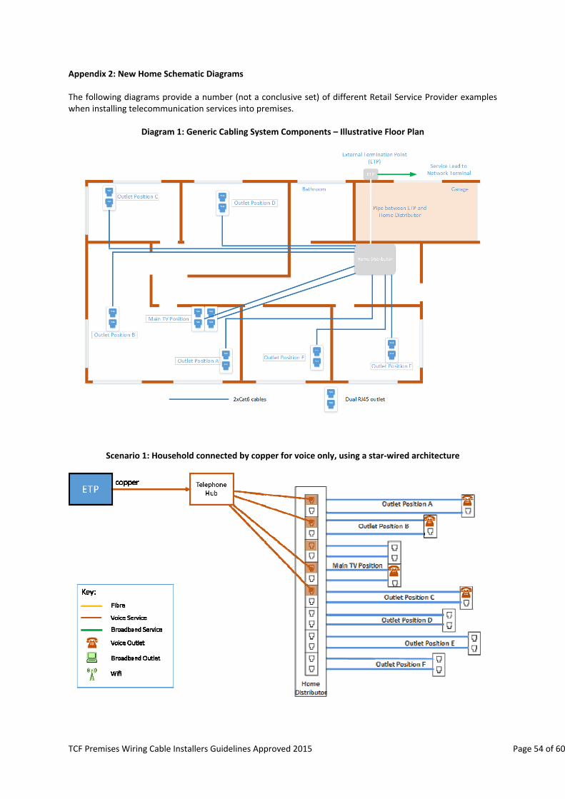
TCF Premises Wiring Cable Installers Guidelines Approved 2015 Page 54 of 60
Appendix 2: New Home Schematic Diagrams The following diagrams provide a number (not a conclusive set) of different Retail Service Provider examples when installing telecommunication services into premises.
Diagram 1: Generic Cabling System Components – Illustrative Floor Plan
Scenario 1: Household connected by copper for voice only, using a star‐wired architecture

TCF Premises Wiring Cable Installers Guidelines Approved 2015 Page 55 of 60
Scenario 2: Household connected by copper for voice and DSL broadband
Scenario 3: Household connected by copper for voice and fibre for broadband. RGW is located physically near the ONT
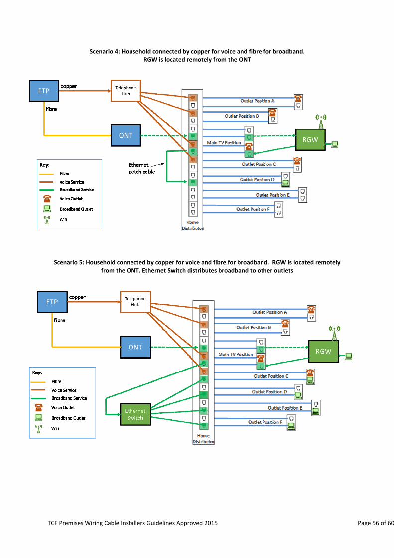
TCF Premises Wiring Cable Installers Guidelines Approved 2015 Page 56 of 60
Scenario 4: Household connected by copper for voice and fibre for broadband. RGW is located remotely from the ONT
Scenario 5: Household connected by copper for voice and fibre for broadband. RGW is located remotely
from the ONT. Ethernet Switch distributes broadband to other outlets
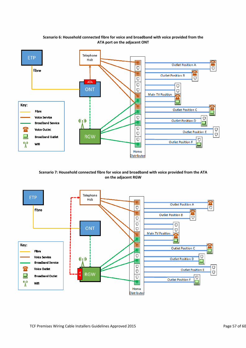
TCF Premises Wiring Cable Installers Guidelines Approved 2015 Page 57 of 60
Scenario 6: Household connected fibre for voice and broadband with voice provided from the
ATA port on the adjacent ONT
Scenario 7: Household connected fibre for voice and broadband with voice provided from the ATA on the adjacent RGW
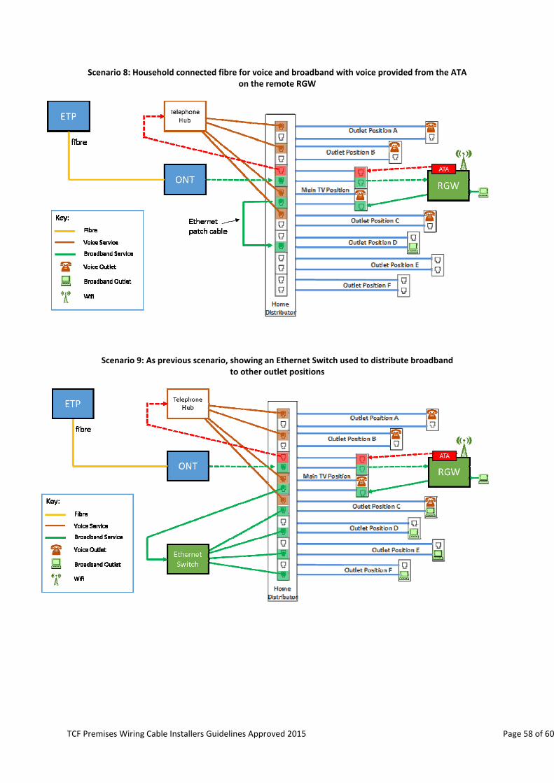
TCF Premises Wiring Cable Installers Guidelines Approved 2015 Page 58 of 60
Scenario 8: Household connected fibre for voice and broadband with voice provided from the ATA on the remote RGW
Scenario 9: As previous scenario, showing an Ethernet Switch used to distribute broadband to other outlet positions

TCF Premises Wiring Cable Installers Guidelines Approved 2015 Page 59 of 60
Appendix 3: For Further Information For further information regarding contact information for Service Providers, Access Network Providers and Local Fibre Companies please visit the TCF website: www.tcf.org.nz/premiseswiring

Page 60 of 60