Embed Size (px)
Citation preview
RP-56-9
The V -N otch W e ir for H o t W a te rB y E D S. SM ITH , JR .,1 PR O V ID EN C E, R. I.
T h is id ea lly s im p le fo rm o f w eir h a s a w id e , a ccu ra te ran ge for h ea d s u p to a b o u t o n e fo o t , is in h e r e n t ly free fro m a era tio n d iff icu ltie s , a n d h a s a b e tte r a g r ee m en t b etw een d a ta fro m v ariou s so u rces th a n w o u ld b e exp ected fro m experien ce w ith o th e r w eir fo r m s g e n e ra lly . T h e presen t paper h a s t o d o s tr ic t ly w ith w eirs o f th e V -n o tch fo rm , o n ly , a n d th e ir v isc o sity co rrec tio n s w ith h o t w a ter, a lth o u g h th e sa m e m e th o d m a y a lso find so m e u se w ith m ore v isco u s liq u id s , su c h as o ils .
GEOM ETRICAL and flow similarity in a weir may reasonably be expected to be accompanied by identical coefficients, regardless of the size and, in th is case, the head.
The V-notch weir is inherently similar in its shape for all heads since its cross-section remains a similar triangle of w idth I and head h, regardless of the magnitude of the head.
The similarity of the triangular cross-section is thus established by the constancy of the ratio
is substantially constant and the stream profile, consequently, is similar regardless of the value of the head.
W ith similar flow lines
expresses the balance between inertia and viscous forces in a liquid having kinematic viscosity v. This is the familiar Reynolds number in which the usual dimension, diam eter d, has been replaced by head h. These three dimensionless ratios may be derived by the methods of dimensional analysis used by Reynolds, Lord Rayleigh, and Buckingham.
For low-viscosity liquids and the usual heads, it is permissible to assume th a t
so th a t [3] becomes• [5]
for a constant value of g, the acceleration due to gravity, i'o r greater convenience in use, th is can be transform ed into
T he formula used herein for the V-notch weir is
using the custom ary mixed b u t convenient units of cubic feet per m inute and inches, respectively, for Q and h. The 5 /2 power results simply from the product of the area, which varies as h2, and the velocity, which varies as h*/*, so th a t the power of h is 2 plus 1/2.
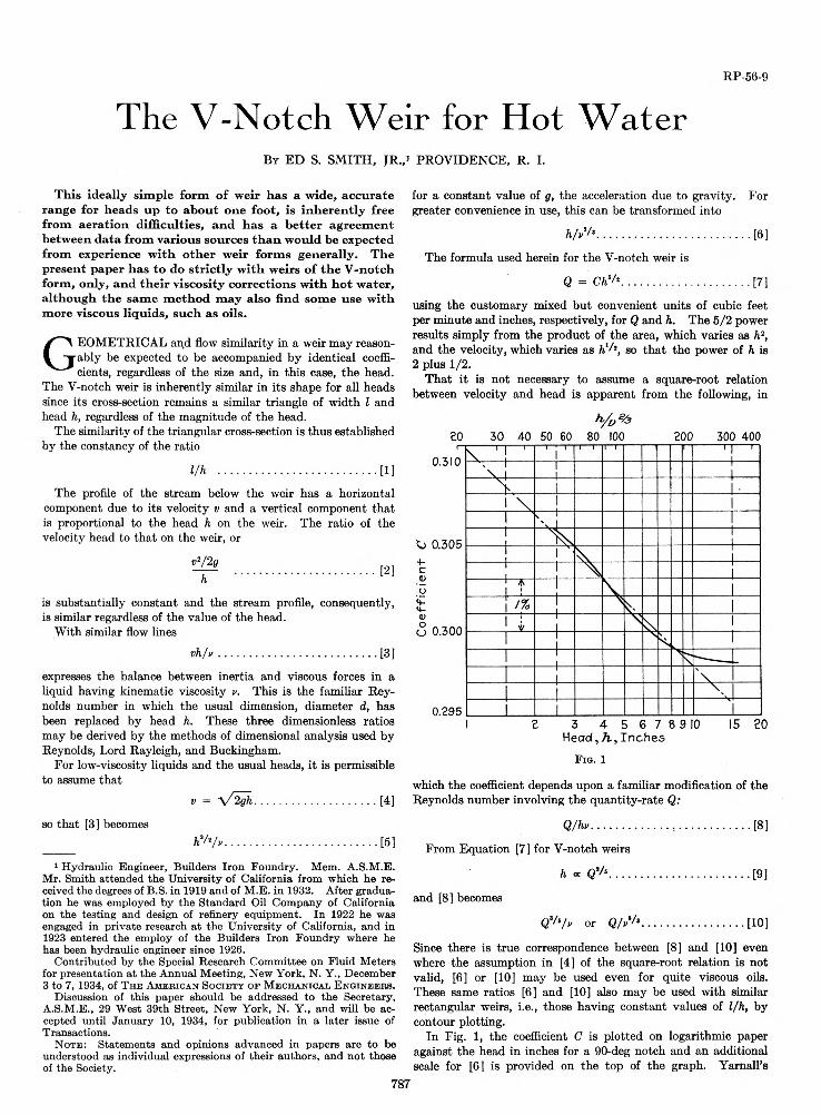
T h a t i t is no t necessary to assume a square-root relation between velocity and head is apparent from the following, in
1 Hydraulic Engineer, Builders Iron Foundry. Mem. A.S.M.E. Mr. Smith attended the University of California from which he received the degrees of B.S. in 1919 and of M.E. in 1932. After graduation he was employed by the Standard Oil Company of California on the testing and design of refinery equipment. In 1922 he was engaged in private research at the University of California, and in 1923 entered the employ of the Builders Iron Foundry where he has been hydraulic engineer since 1926.
Contributed by the Special Research Committee on Fluid Meters for presentation at the Annual Meeting, New York, N. Y., December3 to 7, 1934, of T h e A m e r i c a n S o c i e t y o f M e c h a n i c a l E n g i n e e b s .
Discussion of this paper should be addressed to the Secretary, A.S.M.E., 29 West 39th Street, New York, N. Y., and will be accepted until January 10, 1934, for publication in a later issue of Transactions.
N o t e : Statements and opinions advanced in papers are to b e
understood as individual expressions of their authors, and not those of the Society.
787
Since there is true correspondence between [8] and [10] even where the assumption in [4] of the square-root relation is not valid, [6] or [10] m ay be used even for quite viscous oils. These same ratios [6] and [10] also m ay be used w ith similar rectangular weirs, i.e., those having constant values of l/h , by contour plotting.
In Fig. 1, the coefficient C is plotted on logarithmic paper against the head in inches for a 90-deg notch and an additional scale for [6] is provided on the top of the graph. Y am all’s
The profile of the stream below the weir has a horizontal component due to its velocity v and a vertical component th a t is proportional to the head h on the weir. The ratio of the velocity head to th a t on the weir, or
and [8] becomes
From Equation [7] for V-notch weirs
which the coefficient depends upon a fam iliar modification of the Reynolds num ber involving the quantity-rate Q:
788 TRANSACTIONS OF T H E A M ERICA N SOCIETY OF M ECHA NICA L E N G IN EE R S
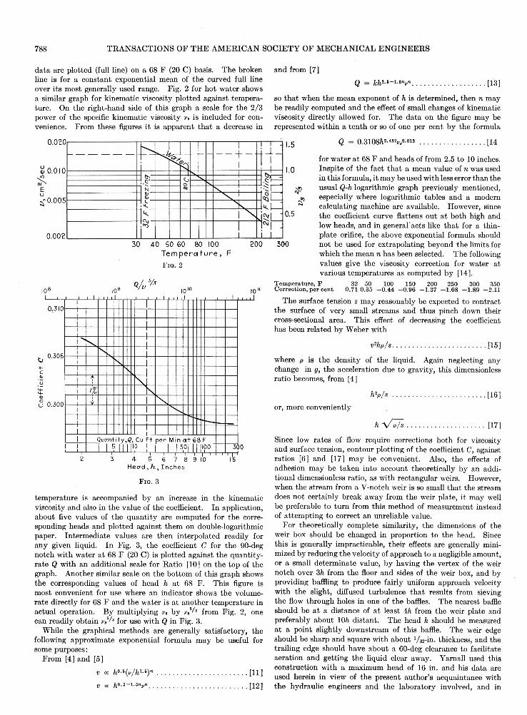
data are plotted (full line) on a 68 F (20 C) basis. The broken line is for a constant exponential mean of the curved full line over its most generally used range. Fig. 2 for hot w ater shows a similar graph for kinematic viscosity plotted against tem perature. On the right-hand side of this graph a scale for the 2/3 power of the specific kinematic viscosity v, is included for convenience. From these figures it is apparent th a t a decrease in
and from [7]
so th a t when the mean exponent of h is determined, then n may be readily computed and the effect of small changes of kinematic viscosity directly allowed for. The data on the figure may be represented within a ten th or so of one per cent by the formula
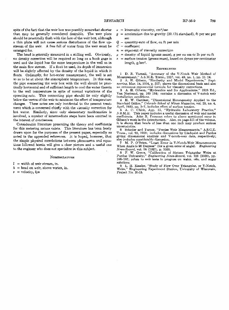
F i g . 3
tem perature is accompanied by an increase in the kinematic viscosity and also in the value of the coefficient. In application, about five values of the quantity are computed for the corresponding heads and plotted against them on double-logarithmic paper. Interm ediate values are then interpolated readily for any given liquid. In Fig. 3, the coefficient C for the 90-deg notch w ith w ater a t 68 F (20 C) is plotted against the quantity- rate Q w ith an additional scale for Ratio [10] on the top of the graph. Another similar scale on the bottom of this graph shows the corresponding values of head h a t 68 F. This figure is most convenient for use where an indicator shows the volume- rate directly for 68 F and the w ater is a t another tem perature in actual operation. By multiplying va by from Fig. 2, one can readily obtain for use with Q in Fig. 3.
While the graphical methods are generally satisfactory, the following approximate exponential formula m ay be useful for some purposes:
From [4] and [5]
for w ater a t 68 F and heads of from 2.5 to 10 inches. Inspite of the fact th a t a mean value of n was used in this formula, it may be used w ith less error than the usual Q-h logarithmic graph previously mentioned, especially where logarithmic tables and a modern calculating machine are available. However, since the coefficient curve flattens out a t both high and low heads, and in general'acts like th a t for a thin- p late orifice, the above exponential formula should no t be used for extrapolating bejrond the limits for which the mean n has been selected. The following values give the viscosity correction for water at various tem peratures as computed by [14].
T em peratu re , F C orrection, per cent
32 50 0.71 0.35
100- 0.44
150- 0.96
200- 1.37
250 300 350 - 1.68 - 1.89 - 2.11
The surface tension s may reasonably be expected to contract the surface of very small streams and thus pinch down their cross-sectional area. This effect of decreasing the coefficient has been related by Weber with
where p is the density of the liquid. Again neglecting any change in g, the acceleration due to gravity, this dimensionless ratio becomes, from [4]
or, more conveniently
Since low rates of flow require corrections both for viscosity and surface tension, contour plotting of the coefficient C, against ratios [6] and [17] may be convenient. Also, the effects of adhesion m ay be taken into account theoretically by an additional dimensionless ratio, as w ith rectangular weirs. However, when the stream from a V-notch weir is so small th a t the stream does not certainly break away from the weir plate, it may well be preferable to tu rn from this method of measurement instead of attem pting to correct an unreliable value.
For theoretically complete similarity, the dimensions of the weir box should be changed in proportion to the head. Since this is generally impracticable, their effects are generally minimized by reducing the velocity of approach to a negligible amount, or a small determ inate value, by having the vertex of the weir notch over 3h from the floor and sides of the weir box, and by providing baffling to produce fairly uniform approach velocity w ith the slight, diffused turbulence th a t results from sieving the flow through holes in one of the baffles. The nearest baffle should be a t a distance of a t least 4h from the weir plate and preferably about 10/a. distant. The head h should be measured a t a point slightly downstream of this baffle. The weir edge should be sharp and square w ith about 1/ 3 2 - i n . thickness, and the trailing edge should have about a 60-deg clearance to facilitate aeration and getting the liquid clear away. Yamall used this construction w ith a maximum head of 16 in. and his data are used herein in view of the present author’s acquaintance with the hydraulic engineers and the laboratory involved, and in
RESEARCH RP-56-9 789
spite of the fact th a t the weir box was possibly somewhat shorter than m ay be generally considered desirable. The weir plate should be practically flush with the face of the weir box, although a thin p late will not cause serious disturbance of the flow upstream of the weir. A free fall of w ater from the weir m ust be arranged for.
The head is generally measured in a stilling well. Obviously, no density correction will be required so long as a hook gage is used and the liquid has the same tem perature in the well as in the main flow stream. If a float be used, its depth of immersion will be slightly affected by the density of the liquid in which it floats. Ordinarily, for hot-water measurement, the well is set so as to be a t about the atmospheric tem perature. In this case, the pipe connecting the weir box w ith the well should be practically horizontal and of sufficient length to cool the w ater therein to the well tem perature in spite of normal variations of the operating rate. This connecting pipe should lie only slightly below the vertex of the weir to minimize the effect of tem perature changes. These notes are only incidental to the present trea tment which is concerned chiefly w ith the viscosity correction for hot water. Similarly, since only elementary mathem atics is involved, a number of interm ediate steps have been om itted in the interest of conciseness.
Considerable literature presenting the theory and coefficients for this metering means exists. This literature has been freely drawn upon for the purposes of the present paper, especially as noted in the appended references. I t is hoped, however, th a t the simple physical correlations between phenomena and equations followed herein will give a clear picture and a useful one to the engineer who does not specialize in th is subject.
N OMENCLATUHE
I = w idth of weir stream, in. h = head on weir, above vertex, in. v = velocity, fps
v = kinematic viscosity, cm2/secg = acceleration due to gravity (32.174 standard), f t per sec per
secQ = quantity-rate of flow, cu ft per min C = coefficientn = exponent of viscosity correctionP = density of liquid (grams mass), g per cu cm or lb per cu ft s = surface tension (grams mass), based on dynes per centimeter
length, g /sec2.
R e f e r e n c e s
1 D. R. Yarnall, “Accuracy of the V-Noteh Weir Method of Measurement,” A.S.M.E. Trans., 1927, vol. 49, no. 1, pp. 21-24.
2 A. H. Gibson, “Similarity and Model Experiments,” Engineering, Mar. 14, 1924, p. 327; shows the dimensional basis and also an erroneous exponential formula for viscosity corrections.
3 A. H. Gibson, “Hydraulics and Its Applications,” 1925 Ed., Van Nostrand, pp. 160-164; contains a discussion of V-notch weir installation conditions.
4 H. W. Gardner, “Dimensional Homogeneity Applied to the Standard Orifice,” Colorado School of M ines Magazine, vol. 23, no. 4, April, 1933, pp. 5-7, includes effect of surface tension.
5 A. C. Chick, App. 15, “Hydraulic Laboratory Practice,” A.S.M.E. This paper includes a useful discussion of weir and model coefficients. John R. Freeman refers to above mentioned error in Gibson’s work in the Introduction. Also, on page 511 of the volume, it is shown that heads of less than one inch may produce serious uncertainties.
6 Schoder and Turner, “Precise Weir Measurements,” A.S.C.E. Trans., vol. 93, 1929; includes discussions by Lindquist and Pardoe giving dimensional analysis and V-notch-weir data, respectively; also includes considerable discussion.
7 M. P. O’Brien, “Least Error in V-Notch-Weir Measurements When Angle is 90 Degrees” (for a given error of angle). Engineering News-Record, vol. 98 (1927), p. 1030.
8 F. W. Greve, “Calibration of Sixteen Triangular Weirs at Purdue University,” Engineering News-Record, vol. 105 (1930), pp. 166-167; refers to weir tests in progress on water, oils, and sugar solutions.
9 L. H. Kessler, “Study of Flow Over Triangular, or V-Notch, Weirs,” Engineering Experiment Station, University of Wisconsin, Project No. H-15.