Embed Size (px)
Citation preview
THERMOMECHANICAL CONTACT PHENOMENAAND WEAR OF S .IDING COIV ONENTS
DTICAj ELECTE
Fin'.l Report - AUG 15 1989
O submitted to
Office of Naval Rese 1 rch
Co tract No. N0001 4-8; -K-01 25Period Covered: January 1, 1987 to Decemi3er 31, 1988
by
Francis E. Kennedy Jr.
Professor of Engine::rlng
and
Beda M.M. E-spinoza, Susanne M. Pepp. 'and Lin TangGraduate Research Assistar s
Thayer Scool of Engineering
Dartmouth Cc" ge
Hanover, New Hamp ire 03755
SJuly 1989
Repro Juction in whole or in part is permitted for any purpose
by the United States Government
SECURITY CLASSIFICATION OF THIS PAGE
REPORT DOCUMENTATION PAGEla. REPORT SECURITY CLASSIFICATON lb RESTRICTIVE MARKINGS
Unclassified
2a. SECURITY CLASSIFICATION AUTHORITY 3 DISTRIBUTION/AVAILABILITY OF REPORT
Approved for public release
2b. DECLASSiFICATION i DOWNGRADING SCHEDULE Distribution unlimited
4 PERFORMING ORGANIZATION REPORT NUMBER(S) S MONITORING ORGANIZATION REPORT NUMBER S)
6a. NAME OF PERFORMING ORGANIZATION 6b OFFiCE SYMBOL 7a NAME OF MONITORING ORGANIZATION
Dartmouth College (if applicable) Office of Naval Research
6c. ADDRESS (City, State, and ZIPCode) 7b ADDRESS (City, State. and ZIP Code)
Thayer School of Engineering 800 North Quincy St.
Hanover, NH 03755 Arlington, VA 22217-5000
8a. NAME OF rUNDING/SPONSORING I8b OFiCE SYMBOL 9 PROCUREMENT INSTRUMENT IDENTIFICATION NuMBERORGANIZATION (If applicable)Office of Naval Research 1131 N00014-87-K-0125
8c. ADDRESS.(City, State, and ZIP Code) 10 SOURCE OF FUNDING NUMBERS
Materials Division PROGRAM PROJECT TASK WORK j%,T
800 North Quincy St. ELEMENT NO NO NO ACCESSION NO
Arlington, VA 22217-5000 1131 4316004-01
11 TITLE (Include Security Classification)
Thermomechanical Contact Phernmena and Wear of Sliding Components
12 PERSONAL AUTHOR(S)
Francis E. Kenned Jr., Beda M.M. Esninnza. _q nnA M. Pr" T. p-t
13a TYPE OF REPORT 13b TIME COVERED 14 DATE OF REPORT (Year, Month, Day) 15. PAGE COuNTFinal I FROM 87/1/1 T08 8 /1 2 / 3 1989 July 31 64
16 SUPPLEMENTARY NOTATION
17 COSATI CODES 18 SUBJECT TERMS (Continue on reverse if necessary and identif by block number)FIELD iGROUP SUB-GROUP ,Mechanical face seals, wear,' friction, ceramic coatings..
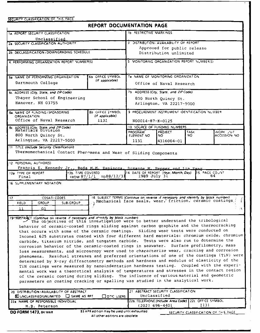
19- AB1TR T (Continue on reverse if necessary and identify by block number)The objectives of this investigation were to better understand the tribological
behavior of ceramic-coated rings sliding against carbon graphite and the thermocracking
that occurs with some of the ceramic coatings. Sliding wear tests were conducted on
Inconel 625 substrates coated with four different hard materials: chromium oxide, chromium
carbide, titanium nitride, and tungsten carbide. Tests were also run to determine the
corrosion behavior of the ceramic-coated rings in seawater. Surface profilometry, mass
loss measurements, and microscopy were used to characterize wear, cracking and corrosion
phenomena. Residual stresses and preferred orientations of one of the coatings (TiN) were
determined by X-ray diffractometry methods and hardness and modulus of elasticity of the
TiN coatings were measured by nanoindentation hardness testing. Coupled with the experi-
mental work was a theoretical analysis of temperatures and stresses in the contact region
of the ceramic coating during sliding. The influence of various material and geometric
parameters on coating cracking or spalling was studied in the analytical work.
20 DISTRIBUTION/AVAILABILITY OF ABSTRACT 21 ABSTRACT SECURITY CLASSIFICATION
91 UNCLASSIFIED/UNLIMITED 0 SAME AS RPT C: DTIC USERS Unclassified
22a NAME OF RESPONSIBLE INDIVIDUAL 22b TELEPHONE (Include Area Code) 22c OFFICE SYMBOL
M.B. Peterson (202) 696-4401 1131
DD FORM 1473,84 MAR 83 APR edition may be used until exhausted SECURITY CLASSIFICATION OF 7-S PAGEAll other editions are obsolete
THERMOMECHANICAL CONTACT PHENOMENA
AND WEAR OF SLIDING COMPONENTS
Final Report
submitted to
Office of Naval Research
Contract No. N0001 4-87-K-01 25
Period Covered: January 1, 1987 to December 31, 1988
by
Francis E. Kennedy, Jr.
Professor of Engineering
and
Beda M.M. Espinoza, Susanne M. Pepper and Lin Tang
Graduate Research Assistants
Thayer School of Engineering
Dartmouth College
Hanover, New Hampshire 03755
July 1989
Reproduction in whole or in part is permitted for any purpose
by the United States Government
FOREWORD
Work at the Thayer School of Engineering at Dartmouth College on this researchproject has been sponsored by Office of Naval Research Contract Number N00014-87-K-01 25. Drs. Peter J. Blau and A.William Ruff and Mr. Marshall B. Peterson were the ONRScientific Officers for the project.
The authors gratefully acknowledge the assistance of V.A. Surprenant in X-raydiffractometry and optical microscropy work and the personnel of the Dartmouth ElectronMicroscope Facility, particularly Ms. Louisa Howard, for assistance with scanning electronmicroscopy. Union Carbide Corp. and EG & G Sealoi contributed materials for use in thetest program. Dr. J.A. Sue of Union Carbide Corp. provided beneficial assistance anduseful information during the course of the project. Nanoindentation testing to determinemodulus of elasticity and hardness of the coatings was graciously done by J. R. Keiser ofOak Ridge National Laboratory.
ABSIRAC
The objectives of this investigation were to better understand the tribologicalbehavior of ceramic-coated rings sliding against carbon graphite and the thermocrackingthat occurs with some of the ceramic coatings. Sliding wear tests were conducted onInconel 625 substrates coated with four different hard materials: chromium oxide,chromium carbide, titanium nitride, and tungster :"'-bide. Tests were also run todetermine the corrosion behavior of the ceramic-i -,ted rings in seawater. Surfaceprofilometry, mass loss measurements, and microscopy were used to characterize wear,cracking and corrosion phenomena. Residual stresses and preferred orientations of oneof the coatings (TiN) were determined by X-ray diffractometry methods and hardness andmodulus of elasticity of the TiN coatings were measured by nanoindentation hardnesstesting. Coupled with the experimental work was a theoretical analysis of temperaturesand stresses in the contact region of the ceramic coating during sliding. The influence ofvarious material and geometric parameters on coating cracking or spalling was studied inthe analytical work.
DI stribi t lon/I
Ava'labil1ty CodDs
ii ~:Avi1 aind/orD sta
TABLE OF CONTENTS
FOREWORD --------------------------------------------------------------------------------- ii
ABSTRACT --------------------------------------------------------------------------------
TABLE OF CONTENTS --------------------------------------------------------------- iii
1. INTRODUCTION -------------------------------------------------------------------------- 1
2. METHODS --------------------------------------------------------------------------------------- 2
3. SIGNIFICANT RESULTS -------------------------------------------------------------------- 3
4. LIST OF PUBLICATIONS RESULTING FROM THIS RESEARCH -------------- 6
5. ABSTRACTS OF THESES ------------------------------------------------------------------ 7
6. COPIES OF TECHNICAL PAPERS ------------------------------------------------------ 12
6.1 "Thermomechanical Analysis of Dry Sliding Systems" .........-------------------- 13
6.2 "Contact Conditions and Wear of Hard Seal Faces Against Carbon Graphite" 24
6.3 "Thermocracking and Wear of Ceramic-Coated Face Seals for Salt Water
Applications" ------------------------------------------------------------------------------- 31
6.4 "Factors Affecting the Sliding Performance of Titanium Nitride Coatings" 57
iii
1. INTRODUCTION
Whenever flat, conforming rings are p!oced together and sliding commences, thereis solid-solid contact between the rings in small, discrete spots which constitute the realarea of contact. This solid-solid contact occurs whether the contacting rings are dry, asin annular disk brakes, or "lubricated", as in mechanical face seals. The thin layer of
sealed fluid which is assumed to be present between the seal faces in the latterapplication does not prevent contact between the flat seal rings. The solid-solid contact
is responsible for most of the friction which occurs between the sliding rings and is also
the origin of the mechanical consequences of friction, i.e., frictional heating, near-surface plastic deformation, and wear of the contacting ring surfaces. The resultingwear can be the cause of early failure of the sliding components.
In order to limit wear in face seals, at least one of the sealing faces is usually made
of a hard, wear-resistant material. In recent years there has been much interest inwear-resistant ceramics for hard seal face applications. Frequently they would be usedin contact with a sea' face made from carbon graphite. Several problems exist with
ceramic seal rings, however. They are difficult to form in the configurations usually usedin face seals and they are so brittle that they require special care in handling. An
alternative to ceramic seal rings has been proposed - ceramic or cermet coatings onmetallic ring substrates.
The objectives of this investigation were to better understand the tribological
behavior of ceramic- or cermet-coated mechanical face seal rings during sliding contact.
Of particular interest were the tribological performance of the coatings in sliding contactagainst carbon graphite seal rings, the failure mechanisms that could limit theusefulness of the coatings, and the corrosion resistance of the coating/substrate system.
This research program was a follow-up to an earlier project, ONR contract
N00014-81-K-0090. Test techniques and analytical methods had been developed in
that earlier work for studying the tribological behavior of sliding conformal contacts, suchas the seal rings of mechanical face seals. Many of those methods were used in this
study.
• • I I i II I I I I I I I l1
2. METHDS
Sliding wear tests were conducted on Inconel 625 seal rings coated with four
different hard materials: chromium oxide, chromium carbide, titanium nitride, and
tungsten carbide. In all tribotests, the coated rings were slid against a commercial seal
ring made from a resin-impregnated grade of carbon graphite for sliding distances
ranging from 100 to 500 km. The sliding speed was generally 4.7 m/s and normal loads
of 50 N and 100 N were applied to the rings. The flat ring-shaped contact area had a
mean diameter of 5 cm and a radial width of about 2.5 mm. This gave a nominal contact
area of 4 cm 2 and nominal contact pressures ranging from 125 to 250 kPa. Multiple
wear tests were run for each material.
Tests were also conducted to determine the corrosion behavior of the ceramic-
coated rings in seawater. For the corrosion tests, sections of the coated rings were
placed in an agitated salt water solution and were left at room temperature for 30 and
60 day periods.
Surface profilometry, mass loss measurements, and optical and scanning electron
microscopy were used to characterize wear, cracking and corrosion phenomena.
Residual stresses and preferred orientations of one of the coatings (TiN) were
determined by X-ray diffractometry methods. The residual stress measurement used the
sin 2' technique. Hardness and modulus of elasticity of the TiN coatings were
measured by nanoindentation hardness testing.
Coupled with the experimentation was a theoretical analysis of temperatures and
stresses in the contact region of the ceramic coating during sliding. The analysis was
done using finite element methods. The Thermap finite element code was used for
surface temperature prediction and the Adina stress and deformation analysis code was
used for thermoelastic and thermo-elasto-plastic analysis of the contact region. The
influence of various material and geometric parameters on coating cracking and
spalling was studied in the analytical work.
2
3. SIGNIFICANT RESULTS
The results of this research are contained in four theses and four technical papers
that were completed during or just after the project period. The list of theses and
technical papers is included in Section 4 of this report. Abstracts of the four theses areincluded in Section 5 and copies of the papers are included in Section 6. The majorresults will be summarized here. Reference will be made to the relevant thesis or paper,and those publications may be consulted for more details.
Each of the coatings tested in this program, tungsten carbide, chromium carbide,
titanium nitride and chromium oxide, all on Inconel 625 substrates, had low wear rates
and low friction during sliding against carbon graphite seal rings. The wear rates werelower than for metallic seal face materials and nearly as low as had been determined
earlier for monolithic silicon carbide [2,5]. Friction coefficients were low (approximately0.10) for all coatings. On regular occasions, though, the friction increased for a short
time to a value approaching 0.3, and that rise was attributed to the presence of carbongraphite wear debris at the contact interface (6].
Despite the good friction and wear results, most of the coatings displayed a
deficiency which could limit their durability in salt water sealing applications.Three different tungsten carbide coatings were tested, two of which had been
applied by the detonation gun process and one by plasma spraying [3]. Each of the WC
coatings had a different metallic binder. The plasma sprayed had also been heattreated after spraying in order to improve the bond between coating and substrate.
All tungsten carbide coatings show evidence of some surface pitting resulting from
both initial porosity and the occasional spalling of a carbide particle from the surface(1,3]. The amount of pitting can be reduced and the bond strength of the coating/
substrate interface can be increased by heat treating the coated rings [3]. Diffusionprocesses during the heat treatment can reduce the resistance of the Inconel 625substrate to corrosion in salt water by sensitizing the material at the grain boundaries in
the region adjacent to the coating (3,7].The wear process for the tungsten carbide coatings was one of wear of the metallic
binder, causing the carbide particles to protrude slightly from the surface. The carbide
particles then wore slowly by a polishing process, resulting in flat carbides [7]. Therewas no influence of coating thickness on either friction or wear of the tungsten carbide
coatings (3].The chromium carbide coatings displayed the lowest wear rates (mass loss per unit
time) of all the coatings tested [7]. When measured on a volumetric basis, the wear rate
of the tungsten carbide coatings was about as low as that of chromium carbide. Wear of
3
the carbon graphite in contact with the chromium carbide rings was also less than orequal to that measured with the other coatings. Two slightly different chromium carbidecoatings were tested [3]. The chromium carbide coating with the smaller nickelchromium particle size (coating H) showed even better wear resistance than did theother chromium carbide coating tested [7]. Neither of the chromium carbide coatingsshowed any evidence of thermocracking in the tribotests, but they showed very slightmass losses in the corrosion tests [3,7].
The plasma sprayed chromium oxide coatings had lower mass wear rates than
tungsten carbide, but higher volumetric wear [1,7]. Although they have good wearresistance, the chrome oxide coatings showed a tendency to thermocrack [1]. The
cracks originate on the sliding surface and are oriented perpendicular to the slidingdirection [1,7]. The severity of thermocracks increased with increases in normal load [1].
Owing to the slow nature of the PVD coating process, titanium nitride coatings havea limited thickness. Although they have low wear rates when the coating is act, thewear is finite and eventually the coatings get quite thin. When this happens there is a
tendency for the coatings to spall and this results in a very significant increase in wearrate, owing to the presence of hard, abrasive third bodies between the seal faces [1].
An in-depth study of the tribological behavior of titanium nitride coatings showed
that the wear rate of Inconel 625 without TiN coating was at least seven times higher
than that with coating and the friction coefficient was also higher [4]. The frictioncoefficient of TiN-coated Inconel 625 was about 0.1 whereas the uncoated Inconel 625had a friction coefficient of 0.18. Polishing and abrasion processes were the major wear
mechanisms of TiN coating [4,8].
Coatinn thickness is an important factor affecting the durability of the TiN coatings[4,8]. The tendency of spalling and delamination of the coatings increased withincreases in the coating thickness. Unlike thicker coatings, the failure mode of the 4.6
pim thick TiN coating was a gradual wear process, even though the wear rate was a little
bit higher than for the 12 pLm and 28 g~m thick coatings (4].The modulus of elasticity of the 4.6 lam thick TiN coating was higher than those ot
the 12 lam and 28 gm thick coatings [4,8]. The wear rate decreased as the coatingmodulus decreased, but the tendency for spalling and delamination of the coatings
increased.The residual stresses in the PVD arc evaporated TiN coatings were compressive
and a relatively higher compressive residual stress occurred in the thinner coating [4,8].The residual stresses were beneficial to the stability of coatings because the tensile
stresses that occur in the coatings during sliding were reduced. This effect was more
obvious in the thinner coating [4].
4
All PVD arc evaporated TiN coatings had very high (111) preferred orientations [4].
The 12 g±m coating had a higher degree of (111) preferred orientation and also had the
lowest hardness. The preferred orientations have an influence on the sliding behavior of
TiN coatings because they change the surface conditions of the coatings, such as
hardness and densification [4,8].
In an attempt to understand the reasons for the coating vailures noted in some
tests, an analytical study of thermal and thermomechanical phenomena near the sliding
contacts was carried out. Finite element techniques were used in the analysis. The
temperature distribution in the sliding contact region was determined using our
specially- developed Thermap thermal analysis program, and the temperature
distribution was used, along with mechanical normal and tangential tractions in the
contact region, as input to an Adina-based thermoelastic or thermo-elasto-plastic
analysis of stresses and deformation [2,5]. A suite of interconnected programs was
created to enable the analysis to proceed automatically once the problem geometry
(including coating thickness) and boundary conditions were specified [2].
It was found using the finite element packages that the stress field around a sliding
contact is dominated by the thermal contribution resulting from frictional heating [5].
That contribution tends to cause tensile stresses in the coating, acting in the sliding
direction. The magnitude of the tensile stresses is dependent primarily on the difference
in thermal expansion coefficient between coating and substrate, as well as the thermal
properties of the coating [5]. The surface temperatures and resulting tensile thermal
stress are higher if the coating has a low thermal conductivity and a large difference
between coefficient of thermal expansion of coating and substrate, as is the case with
chrome oxide [1]. The highest tensile stress acts in the sliding direction and occurs at
the sliding surface. Thus, that stress is probably responsible for the thermocracking
observed with chrome oxide coatings in this test program [1,7].
5
4. TECHNICAL PUBLICATIONS RESULTING FROM THIS RESEARCH
Theses
1. Espinoza, B.M.M., "Investigating the Failure of Ceramic Coatings for MechanicalFace Seal Applications", Master of Engineering Thesis, Dartmouth College,April 1987.
2. Hussaini, S.Z., "Analytical and Experimental Studies of Hard Face SealCoatings", Master of Engineering Thesis, Dartmouth College, May 1988.
3. Pepper, S.M., "An Investigation into the Wear of Ceramic Coated MechanicalFace Seals", Master of Engineering Thesis, Dartmouth College, January 1989.
4. Tang, L. "Factors Affecting Durability of Titanium Nitride Coatings", Master ofScience Thesis, Dartmouth College, May 1989.
Technical Papers
5. Kennedy, F.E. and Hussaini, S.Z., "Thermomechanical Analysis of Dry SlidingSystems", Computers and Structures, v. 26 (1987), pp. 345-355.
6. Kennedy, F.E., Hussaini, S.Z. and Espinoza, B.M., "Contact Conditions and Wearof Hard Seal Faces", Lubrication Engineering, v.44 (1988), pp. 361-367.
7. Kennedy, F.E., Espinoza, B.M. and Pepper, S.M., "Thermocracking and Wear ofCeramic-Coated Face Seals for Salt Water Applications", to be published inLubrication Engineering.
8. Kennedy, F.E. and Tang, L., "Factors Affecting the Sliding Performance ofTitanium Nitride Coatings", to be published in Proc. 16th Leeds-LyonSymDosium on Tribology, Lyon, France, September 1989.
Technical Reoorts
9. Kennedy, F.E., Espinoza, B.M.M., and Pepper, S.M., "ThermomechanicalContact Phenomena and Wear of Sliding Seal Components", Annual Report1987, ONR Contract N0001 4-87-K-01 25, March 1988.
6
5. ABSTRACTS OF THESES
COMPLETED WITH SUPPORT FROM
ONR CONTRACT NO. N00014-87-K-0125
7
Investigating the Failure of Ceramic Coatings for
Mechanical Face Seal Applications
Beda M. Espinoza
Thayer School of EngineenngDartmouth College
Hanover, New Hampshire 03755
April 3, 1987
ABSTRACT
Ceramic coatings have seen increasing use mainly because of their high resistance towear. These coatings have been used successfully in reducing the wear of machine tools,aircraft and automobile engine parts, etc. It is only recently that research into the applicationof ceramic coatings on mechanical face seals started. The performance of ceramic coatingsfor improved wear performance was promising, but together with this bright prospect, therehave been problems. One major problem that arose was thermocracking of some ceramic
coatings.
The objectives of this investigation were to determine the causes behind thethermocracking of di-chromium tri-oxide and other ceramic coatings and the wearphenomena that occurs when ceramic coated mechanical face seals slide against carbon
graphite. Sliding wear tests were conducted on Inconel 625 face seals coated with five
different ceramics: di-chromium tn-oxide, molybdenum boride, titanium nitride, tungstenboride, and tungsten carbide. Surface profilometry, weight measurements, and microscopy
were the methods used to characterize the wear and failure phenomena. Coupled with
experimentation was a theoretical analysis of temperatures and stresses that occured in theceramic coating. Temperatures and stresses were calculated by using the THERMAP and
ADINA packages, respectively.
The results indicated that thermocracking was caused by the mismatch in mechanical
and thermal properties between the di-chromium t'i-oxide coating and the Inconel 625substrate. Though the wear rate was lowest for di-chromium th-oxide. thermocrackingccuid lead to more severe wear and to early seal failure. The wear of titanium nitridecoatings was through a burnishing type of adhesive wear, but current deposition methods
could not produce thicker coatings, placing titanium nitride coatings at a disadvantage for
.ong term use. Tungsten carbide coating wear was comparable to the wear of previously
mentioned ceramics which was the result of the wear of the softer binder matrix and pitting
due to surface fatigue. Molybdenum boride and tungsten boride coating wear was very high
and their use as coatings for mechanical face seals is not recommended.
I" '' " " '
Analytical and Experimental Studies
on Hard Face-Seal Coatings
by
Syed Zafarulla Hussaini
Thayer School of Engine,:ring
Dartmouth College
Hanover, New Hampshire
ABSTRACT
When two solid bodies are placed in contact the real area of contact is much smaller than the
nominal or apparent area of contacL It is within this real area of contact that the thermal and mechanical
consequences of friction, i.e. wear. frictional heating, and deformation of contacting bodies occur and lead
to thermoelastic instabilities in seal face materials. The primary objective of this work has been to gain
better understanding of contact conditions at the interface between seal rings of mechanical face seals.
Experiments were conducted with wear resistant materials such as SiC. WC, and TiN rubbing
against carbon graphite in a ring-on-ring configuration. An entirely redesigned experimental setup was
employed for this purpose. It was found that contact conditions at the sealing interface varied widely
between the materials used. Contact patch size and friction were also found to change periodically with
time, more frequently for SiC rings than for WC rings. It was also found that fricuon increased
substantially when contact was large. It was determined that during the period of high contact there was
substantial carbon wear which got deposited on the hard ring resulting in increased tendency toward
adhesive wear.
In an attempt to understand the reasons for the coating failures, an analytical study of thermal
and thermomechanical phenomena was carried out. The temperature disubution near the contact region
was determined using THERMAP and it was used, along with normal and tangential Macuons. as input
to an ADINA based thenmo-elasto-plasoc analysis of stresses and deformauons.
I
Thayer School of EngineeringDartmouth College
An Investigation Into the Wear of Ceramic Coated Mechanical Face Seals
Susanne M PepperMaster of Engineering
JANUARY 1989ABSTRACT
Mechanical face seals are used where fluid leakage past a rotating shaft is
possible but must be prevented. Some applications include product pumps, sea water
pumps, and propeller shafts. This study focused on the naval propeller shaft
application of face seals. The two aspects of performance of primary concern are life
and leakage. Since seal design has successfully overcome the problem of excessive
leakage, the principal failure mode is wear. For this reason, ceramics and cermet
coatings have been applied to mechanical face seals, effectively lowering wear rates
and friction coefficients. Recent studies at Thayer School have evidenced their
potential success. In this study two cermet coatings, chromium carbide and tungsten
carbide were tested for their wear behavior. Two different versions of chromium
carbide (differing only in their nickel chromium particle size) and three different typesof tungsten carbide were examined, as well as various thicknesses of tungsten
carbide.Sliding wear tests were conducted of the various coatings on Inconel 625, mated
with a carbon graphite counterface. Surface profilometry, weight measurements,optical and scanning electron microscopy were tools employed to determine the wearbehavior and wear mechanism associated with the various chromium carbide andtungsten carbide coatings. All coatings exhibited low wear rates and frictioncoefficients, comparable if not better than those ceramic coatings previously studied.Both chromium carbides and tungsten carbides appeared to wear by a polishingmechanism. Tungsten carbide coatings were susceptible to pitting due to surfacefatigue. In addition, the heat treatment process of these coatings seemed to havesensitized the material at the grain boundaries of the inconel substrate, reducing itscorrosion resistance. Also, the tungsten carbide coating thickness was determined tohave little if no effect on its wear rate. The chromium carbide coatings experiencedlower wear rates than any of those studied previously. Specifically, the chromiumcarbide coating with the smaller nickel chromium particle size displayed the lowestwear. The chromium carbide softer binder matrix appeared to wear first. Wear of itsmating carbon graphite ring was also less than observed with other coatings. Noevidence of thermocracking was found, even after a high load test, and no evidence of
corrosion could be seen either with the optical or scanning electron microscope.
Therefore chromium carbide coatings seem to be likely candidates for naval face sealapplications, and further study of these in an actual face seal configuration isrecommended.
ii
Thayer School of EngineeringDartmouth College
"Factors Affecting Durability of Titanium Nitride Coatings"
Lin Tang
Master of Science
May 1989
Abstract
Many kinds of ceramic coatings have been developed and usedon metallic substrates to improve the wear resistance of slidingcomponents. Wear is not the only way ceramic-coated components canfail. Other failure modes can also be caused by thermal andmechanical sliding phenomena.
The objective of this ONR-sponsored research work is to gain abetter understanding of the wear and thermoc:-acking of TiN-coatedInconel 625 rings in dry sliding contact. One of the potentialapplications of the TiN-coated rings is face seal components used insubmarines, where they would be in contact with carbon graphiterings. Tribological behavior of the TiN-coated Inconel 625 rings hasbeen investigated with the aid of a computer-assisted profilometrysystem, optical microscopy, scanning electron microscopy and finiteelement thermal and thermomechanical analysis. Residual stressesand preferred orientations in TiN coatings were determined by X-raydiffractometry methods. Both hardness and Young's modulus of TiNcoatings were measured by nanoindentation hardness testing.
The results showed that both the wear and the frictioncuefficient of Inconel 625 were significantly reduced by TiN thin hardcoating. The tendency of spalling and delamination of TiN coatingincreased with increasing the coating thickness, but wear was greatestfor the thinnest coating. TiN coating with higher substrate hardnesshad better wear resistance. The compressive residual stress wasbeneficial to the durability of TiN coating. Higher hardness of TiNcoating lowered the wear rate while increasing the possibility of
brittle fracture. (111} preferred orientations were observed in all PVDarc evaporated TiN coatings.
ii
6. COPIES OF TECHNICAL PAPERS
COMPLETED WITH SUPPORT FROM
ONR CONTRACT NO. N00014-87-K-0125
12
12
. ..p. , . l a ma i ni
- ii-= , - -,._ __ _ _ _ _ _ __ _ _ _ _ _
P UrnCI' .n <4<a B':rC Pe-tjm,'r J,'ur~Jih Lid
THERMO-MECHANICAL ANALYSIS OFDRY SLIDING SYSTEMS
F. E. KENNEDY and S. Z. HUSSAINIThaser School of Engineering. Dartmouth College. Hanoser. NH 03'55. U'S A
bstract-This paper discusses the numerical analysis of temperatures and stresses near .,,: -egion, oicontact oetseen flat sliding rings, such as the seal rings or mechanical face seals. Of particular interestwere rings ha.ing a hard. wear-resistant coating on a ductile metallic substrate. The temperature di,tribu-tnon in the sliding contact region was determined using a specially-developed finite element program, andthat temperature disiribution was used, along with mechanical normal and tangential contact tractions.as input to an ADINA-based thermo-elasto-plastic analysis of stresses and deformations. It was shownthat frictional heating is the dominant contributor to high localized temperatures and stresses around thecontact region. that plastic deformation can occur in the region. and that thermally-induced deformationsand stresses can be a major reason for coating failure. The influence of coating and substrate properties.as well as coating thickness, on the results and on potential failure mechanisms was studied.
INTRODL.CTION body was elastic. The finite element method need notbe subjected to those restrictions and that method
When two flat solids are placed in contact, the real has been used in the work reported here. Techniquesarea of contact is much smaller than the nominal or have been developed for analyzing temperatures andapparent contact area. It is within the real area of stresses in two contacting solids in relative motioncontact that the thermal and mechanical conse- and they were used successfully in an earlier finitequences of sliding friction occur. i.e. frictional element thermal and thermoelastic analysis of slidingheating, near-surface plastic deformation and wear of rings [6]. The methods enable both contactingthe contacting bodies. These thermal and thermo- bodies to be studied simultaneously, thus eliminatingmechanical contact phenomena can be responsible the need for assumptions about partitioning of fric-for failure of sliding mechanical components such as tional heat or distribution of surface tractions. Thebrakes, face seals and slee,,e bearings through such earlier study [6] gae considerable insight into themechanisms as thermocracking ior heat checking) reasons for ihermocracking of sliding metallic ringand excessive wear [I]. In order to understand these surfaces. Based on that elastic analysis it wasfailures it is necessary to study the temperatures, hypothesized. but not prosen. that residual plasticstresses and deformations that arise on and near the strains could be responsible for propagation ofcontacting surfaces as a result of friction, thermally-induced cracks. Finite element methods
Contact spots are subjected to two types of load- can be easily used to predict residual stresses. as vwasIngs: mechanical loads consisting of shear and shown in a recent elato-plastic analysis of a bodynormal tractions, at the contact interface, and beneath a moing heat source [-]rthermal loading -,,ulting from temperature gra- The particular case chosen for stud% here is dr,dients due to frictional heating. It is general[h agreed sliding contact betwseen tw.o fiat rings similar tothat the Interaction %ciocities during sliding are low those found in mechanical face seals Although theenough to permit the use of uncoupled thermal stress conforming rings are nominall, in contact oer theirtheor, in analh.ing the phenomena [21 Thus. two entire circumference, tests hae shossn that thes are,olutions are required the temperature distribution in actual solid solid contact onl, in patches %khich-iround a frictionall-heated contact spot and the coer a small portion of the nominal contact surface•tress distribution due !,, the combnnation of surface [,]. Surface temperatures and wear within thoseractions and temperature gradients. The problems contact patches can become signficant It is Impor-
hase been treated presiousls using integral trans- tant to limit wear of seals and other lidimg com-Orm techniques for both two- and three-dimensional ponents. so seal rings are novs made of
,,,ntacts on the surface of an elastic half-space [3. 4]. ssear-resistant materials %%heneer po-,ble In orderThoe techniques hase recently been extended to the to obtain vear resi,,tance under condition, of high-..,e of a lasered elastic medium subjected to a contact temperature. ring with a ceramic ,ntict-',,%Ing contact [V'J Although those studies hae surface are being deseloped. Such ring, %kould ikelk:. much inszght Into conditions around sliding be used in contact wsith rings made from :arhon
a,ts. the% required seeral assumptions which graphite. a prosen seal ring material Athough ctsm7t their applicability for real sliding components: hae sho\,n that ceramic-coated ring, are sers ssetr
"Istie large body (half-spacei was analzed, all fric- resistant %,.hen sliding against carbon graphite. the%nal heat k.is assumed to enter that bod . and the can suffer from thermocracking or 'palling of the
345
34e F E Kf.'cwv and S Z Hissi1%i
,urta,: c,-artnes [9. 1()] This %kork set out to deter- Experimental "ork had shokn that the contactminc if thermal stresses resulting from frictional spots %%ere approximatel\ reo:tanaular in ,h.pc Lheating are responsible for thermocracking of extending further in the circumferential directionceramic-,coated rings, as ,as earlier shown to be the than radiall\. All tractions at the contact interfacecase th metallic rings [6]. act in either circumferential H or aixial i-) directions.
and in earlier analytical modelling [4. 6) it % as"%NLITIC-L TECHNIQ. ES found that the most important temperature %aria-
tions were those occurring in the N-: plane. For thisreason it was decided to anal.ze the problem onl. in
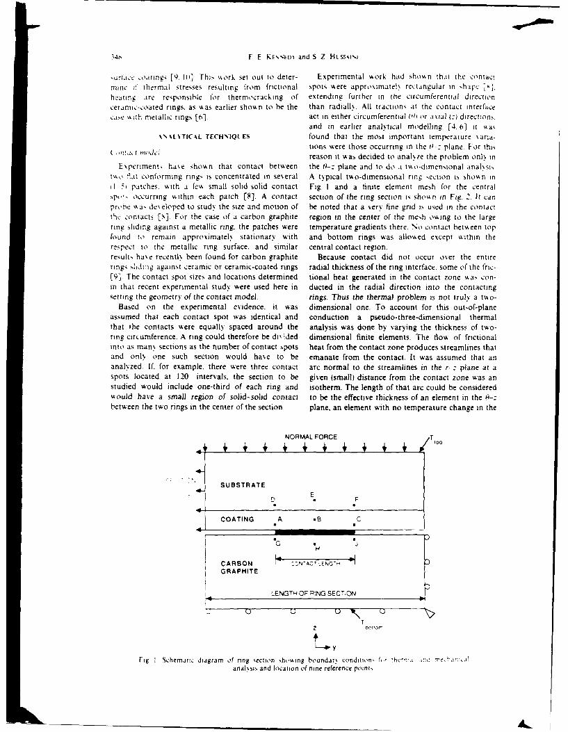
E\perimenti ha%,e shon that contact between the 0-: plane and to do . tvko-dimensional anal.sist, 1at conforming rings is concentrated in se\eral A typical tmo-dimensional ring section is ,hovn inI I 5t patches. \kith a fev, small solid solid contact Fig. I and a finite element mesh for the centralspo,' occurring %4ithin each patch [8]. A contact section of the ring section is shon in FIE 2. It canprone %a- deseloped to study the size and motion of be noted that a very fine grid is used in the contactthc contacts [s] For the case of a carbon graphite region in the center of the mesh owsing to the largering sliding against a metallic ring. the patches were temperature gradients there. No contact betsseen topfound to remain approximately stationary with and bottom rings was allowed except within therespect to the metallic ring surface. and similar central contact region.result ha,,e recentl. been found for carbon graphite Because contact did not occur over the entirerings slid ig against ceramic or ceramic-coated rings radial thickness of the ring interface, some of the fric-[9]. The contact spot sizes and locations determined tional heat generated in the contact zone v.as con-in that recent experimental study were used here in ducted in the radial direction into the contactingsetting the geometry of the contact model, rings. Thus the thermal problem is not truly a two-
Based on the experimental evidence, it was dimensional one. To account for this out-of-planeassumed that each contact spot was identical and conduction a pseudo-three-dimensional thermalthat the contacts were equally spaced around the analysis was done by varying the thickness of two-ring circumference. A ring could therefore be di, ided dimensional finite elements. The flow of frictionalinto as man% sections as the number of contact spots heat from the contact zone produces streamlines thatand onlN one such section would hae to be emanate from the contact. It was assumed that ananal.zed. If. for example. there were three contact arc normal to the streamlines in the r-: plane at aspots located at 120 intervals, the section to be given (small) distance from the contact zone was anstudied would include one-third of each ring and isotherm. The length of that arc could be consideredwould have a small region of solid-solid contact to be the effective thickness of an element in the 0-:between the two rings in the center of the section. plane, an element with no temperature change in the
NORMAL FORCE T
SUBSTRATE: E
C, F
COATING A .B C
G * --1J
CARBON 7hACTENGWIGRAPHITE
LENGTH OF R:NG SECTION
T
z bOa'
Fig Schemati: diagram of ring section howing boundar, condition, f,.'rmcd...r,
anal, sis and location of nine reference points
Thermo-mechanical analysis of dry sliding systems 347
the top half of the model. Following this idea. the.__thickness of each element in the mesh of Fig. 2 was
calculated and used in the thermal analysis.Since each of the ring sections anal.,zed in this
work was similar in shape to that shown in Fig. I.
an automatic mesh generation routine(AUTOMESH) could be employed to create a meshfor any given section. In general the automatic meshgeneration consisted of shrinking or stretching a
______ vell-proven protot.pe mesh such as that in Fig. 2.71 subject to some constraints on element aspect ratio.
The only input variables required by the mesh gener-
n.1 _ . , ation program were the section length, ring heights.
A ring thicknesses (radialL contact dimensions (radial:e--__ and circumferential) and coating thickness.
:eP Thermal analysisie
The thermal analysis used a finite element
re __program (THERMAP) developed specifically for
c- Fig. 2. Central section of mesh generated by AUTOMESH studying the temperature distribution around sliding
n- for 1.0 mm long contact patch. contacts [11, 12]. The program differs from typicalg heat conduction codes in that it solves Fourier's Law
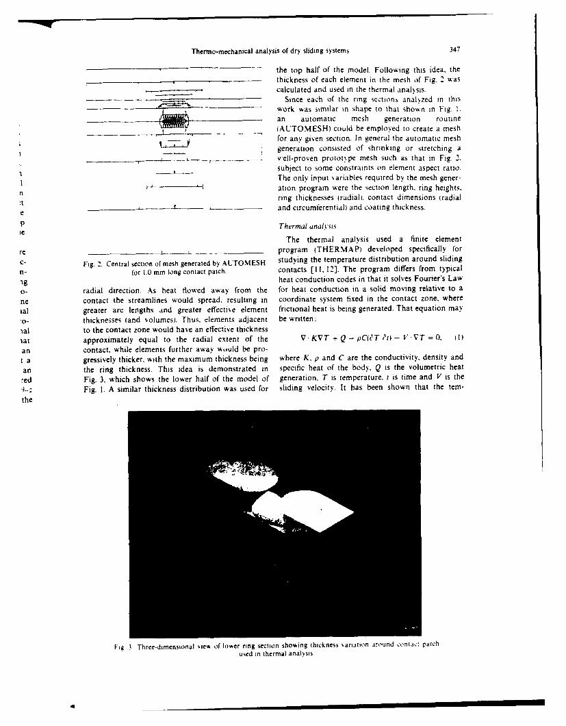
o- radial direction. As heat flowed away from the for heat conduction in a solid moving relative to a
ne contact the streamlines would spread, resulting in coordinate system fixed in the contact zone. where
ial greater arc lengths and greater effecti',e element frictional heat is being generated. That equation may.o- thicknesses land volumes). Thus. elements adjacent be written:
•al to the contact zone would have an effective thicknesstat approximately equal to the radial extent of the V KVT + Q - pC(WT t - V VT = 0. 11)
an contact, while elements further away would be pro-t a gressively thicker, with the maximum thickness being where K. p and C are the conductivity, density and
an the ring thickness. This idea is demonstrated in specific heat of the body, Q is the volumetric heat
red Fig. 3. which shows the lower half of the model of generation, T is temperature. t is time and V is the
9-: Fig. 1. A similar thickness distribution was used for sliding velocity. It has been shown that the tem-
the
Fie 3 Three-dimensional *,iew of lower ring section showing thickness .ariation around contact patchuwed in thermal analysis
34, F E KErsocro and S. Z HtsSAiNO
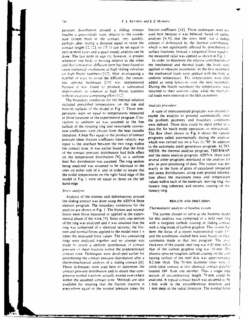
perature distribution around a sliding contact friction coefficient [14]. Those techniques 'ere no,
reaches a quai-stead.' state. relatise to the coordi- used here because it was beliesed. based on earlernaie system fixed in the contact. %er. quickl. analyses [6. 8], that the stress, held ear a siding
perhaps after iding a distance equal to twice the contact is dominated b\ the thermal contribution.contact length [2. 12]. so -T 'r can be set equal to which is not sigfniicantl! affected b\ distribution 0f
zero in most cases and a quasi-steady analysis can be surface tractions. Instead a tangential force equal ,done. The last term in eqn I l . howeser. is present the measured value was applied as sho, n in Fi I
,.khene\er one bod\ is moa.ing relati\e to the other In order to determine the relatise contribut;on, o,
and that consectise dliffusion term has been found to the mechanical and thermal loads, the loads vAert
cause numerical oscillations at high sliding ;elocities applied in separate increments. In the first ncreme.tior high Pecler numbersi [12]. ,fter imestigating a the mechanical loads Asere applied with the bod% ai
number of \%as, to aoid the difficult\, the stream- uniform temperature Thc temperatures Acre thenline upw Ind technique [13] was implemented added as ramp function, o~er the nest micrce.
because it a, flound to produce a substantial During the fourth increment the temperature, "erc
improsement in solution at high Peclet numbers returned to their uniform salue. while the mechar.:-without esceis,,e computing etlort [12] cal loads were remosed in the fifth increment
The boundar\ conditions for the thermal solutionincluded prescribed temperatures on the top and Analysis procedurebottom surfaces of the model in Fig. 1. Those tem-
peratures, were set equal to temperatures measured Asieo necnetdporm sscetdtat those locations in the experimental program. Con- enable the analysis to proceed automaticall once,
\ection to ambient air was assumed at the free the problem geometr\ and boundar) condition,
surface of the rotating ring and reasonable convec- were defined. Those data could be input either to %
tion coefficients %ere chosen from the heat transfer data file. for batch mode operation, or interactiel.
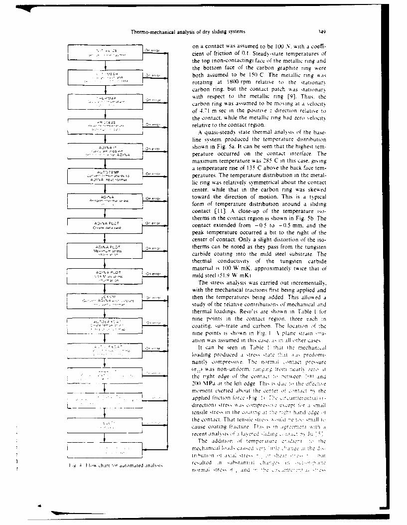
literature. A heat flux equal to the product of contact The flow chart shown in Fig. 4 shows the %ariou,
pressure times friction coefficient times velocity was programs called automaticall. during the anal.,is.
input to the interface between the two rings within which was carried out on a Vax 11-785. In addition
the contact zone. it was earlier found that the form to the automatic mesh generation program. AUTO-
of the contact pressure distribution had little effect MESH. the thermal analysis program. THERIAP.
on the temperature distribution [8]. so a uniform and the stress analysis program. ADINA. there %ere
heat flux distribution was assumed. The ring section several other programs interlaced in the anal\ sis for
being analyzed was assumed to be identical to the pre- or post-processing of data. The output "as pri-
ones on either side of it. and in order to insure this marily in the form of plots of calculated temperate
the nodal temperatures on the right hand edge of the and stress distributions, along with printed informa-
model in Fig. I were set equal to those on the left tion about the maximum stress and temperature
hand edge. values within each of the materials: mo\ ing ring. ta-
tionary ring substrate, and ceramic coating on sta-
Stress analYsis tionary ring.
Analysis of the stresses and deformations aroundthe sliding contact was done using the ADINA finite RESLLTS AND DISCUSSIONelement program. The boundary conditions for theanalssis are shown in Fig. I. The friction and normal Thermoelastic analysis of-haseline sv.steit
forces were those measured or applied in the experi- The system chosen to ser\e as the baseline modei
mental phase of the work [9]. Since only one section for this analysis swas composed of a mild steel rineof the ring was anal~zed and it was assumed that the with a tungsten carbide coating in sliding c,,ntac:Tring \Aas composed of n identical sections. the fric- with a ring made of carbon graphite. This s.stern ha-tion and normal forces applied to the model were I n been the focus of a recent experimental studs '\
times the measured force salues. The to contacting and the conditions studied here were based on mled-
rings , were anal.zed together and no attempt was surements made in that test program The .. 'made to insure a uniform distribution of contact thickness of the coated steel ring was ,43 mm. %% hJLc
pressure or shear traction within the predetermined that of the carbon graphite ring Aa, II) mm Fh,
contact zone. Techniques wAere deseloped earlier for plasma-spra.,,ed tungsten carbide coating on the c,,r-
determining the contact pressure distribution after a tacting surface of the steel disk was approsimatel\thermomechanical analysis of a sliding contact [8]. 0.2 mm thick. The 50 mm diameter ring, ser: .:
Those techniques w~ere used here to determine the solid-solid contact at twso identical contact ptch,'-
contact pressure distribution and to insure that com- located 180 from one another. Thus a single ringpressi\e normal tractions actuall existed eerysshere section of circumferential length -9 mm could bewithin the assumed contact zone Methods are also analyzed. A typical contact patch was assumed to be
available for insuring that the friction traction is I mm Aide in the circumferential direction and
ever,,wbwe-, equal to the normal pressure times the 1 mm deep in the radial direction. The normal force
Thermo-mechanical analysis of dry sliding systems 349
, E ._ on a contact was assumed to be 100 N. with a coeffi-
cient of friction of 0.1. Steady-state temperatures ofthe top inon-contacting) fact of the metallic ring andthe bottom face of the carbon graphite ring "ere
S ,.,,both assumed to be 150 C. The metallic ring Aas...... _______ rotating at 1800 rpm relative to the stationar,
carbon ring. but the contact patch %as stationary
" I. ' with respect to the metallic ring [9]. Thus. thecarbon ring was assumed to he moing at a %elocit%of 4.71 m sec in the positie : direction relatl~e tothe contact. while the metallic ring had zero %elocit)
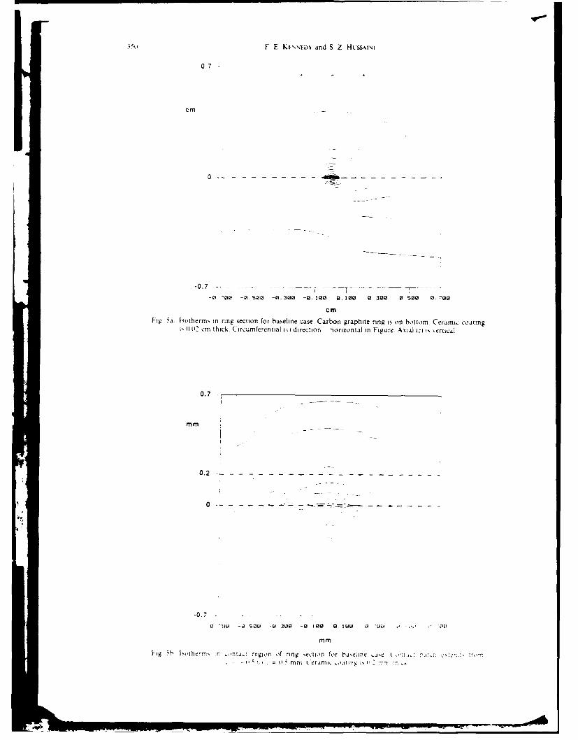
.. .. ,relative to the contact region.:' A quasi-stead) state thermal analysis of the base-
line system produced the temperature distributionshown in Fig. 5a. It can be seen that the highest tem-perature occurred on the contact interface. Themaximum temperature was 285 C in this case. giing
AurT) rEMP O oa temperature rise of 135 C aboe the back face tem-, -:,--t,r peratures. The temperature distribution in the metal-
,o: ,-,a, lic ring was relatively symmetrical about the contacti center, while that in the carbon ring was skewed
0 1 NA eo~,,,, toward the direction of motion. This is a typical.. .form of temperature distribution around a sliding
contact [11]. A close-up of the temperature Iso-therms in the contact region is shown in Fig. 5b. The
CD,'l_ dat aW contact extended from -0.5 to -0.5 mm. and theCreate data osse
peak temperature occurred a bit to the right of thecenter of contact. Only a slight distortion of the iso-
,A°NALr,T therms can be noted as they pass from the tungsten
carbide coating into the mild steel substrate. Thethermal conducutvt of the tungsten carbide
material is X) W inK. approximately twice that ofS ACINA PLOT eo
V,: v .. mild steel 51.9 W mK.The stress analxsis was carried out incrementally.
with the mechanical tractions first being applied andL., then the temperatures being added. This allowed a
... , 'study of the relative contributions of mechanical and
thermal loadings. Resu!ts are shokn in Table I for
nine points in the contact region, three each in
coating. suhvtrate and carbon The location of thenine points is shown in F!g. I A plane strain ,'-ation was assumed in thi, case. a- in all other cases
It can he seen in Table ! that the mechan:.alloading produced a tres, tate tt a- predomi-
nantly compre,,si.e. The normal contact presure
-r ::i %%as non-uniform. rnmtrg from nearhx er,, it... i :--"- =the right edge of -he cont'l,:1 t,, .c c ',)i ind
20) lPa at the left edge Thi .. i., the OiC !11 !
moment e\erted about the center o c,nta.t h the
. applied friction force 'Fig F ,! r eumier:n t -iI r
directioni streN, %%.i, .,,npre .%,, , pt .,,r a niall
tensile streN in the o:,,atInc: It -:h-hand edge ,'
the contact. That tenile i -u, .,ui -e ia' ll i,,cause coating fracture -hi, i in ircmen i th a
recent anal%,i, of i I.tertd ,;;ding , i, h Ju
The addition of !empsermu.i: -r.dici-' *; 0he
- mechanical load, caued . : : .L: :I-he Js-
__. .__ _tributi I .ii st res - - -i a r -Lit
S , th,%, :hari ior a uhImaied analk,.i, resultCd in .uhstantal In
4 I': Th n .r jutomathd ,snaksis n rmr .,,al stress .and
,4
F E KF'tD' and S. Z HLssINI
0.7
cm
0 f" - ,Q---- -
-0.7 .. .. .. . .. .
-O ' -2 -. 300 -0. 02 .100 (.300 0.So ,70
cm
Fig 5a Isotherm, in ring section for baseline case Carbon graphite ring is on bottom Ceramic coating', l02 cm thick Circumferential i ii direction iorizontal in Figure Axial i: , 'ertical
0.7
mm
0.2
-0.7 .
-0 -110 -0 S00 -2 302 -2 100 212 0 100 0 -
mm
Fig 'h Ioiherm, in n-inac: region of ring ecton for l.isin e ,tse n n,,!,: irnmt., --u = mm t-erami, oaingT is' :TvrI m
Thermo-mechanical analysis of dry sliding systems
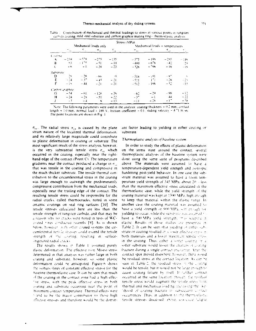
Table :Cormbution of mechanical and thermal loadings to stress at sarious points in Tungstencard" :oatkng. mild steel substrate and carbon graphite maig ring -- thermoelastic anals1is
Stress iMPaiMechanical loads onlh %lechanical loads temperature,
N7 "q 13' - '7I
8 -KS -~I Io -4,14) - t)-6 -41 (
C h l 10 -23 -3216 -06 ~ 6 -
Suh~strateD :1, 0-1 -15 --
F -s -44 10 : l -q 5 I
C arpo'n qraphiteG - 54 -l60 -li .,3s-2 - -9~6 '
H - 24 -2 -t --2-Y13 - -4 -6 1I3-I -IS -
.Note The following parameters here used in the anal'.sis. coating thickness =12mm. contactlength -- : i mm. normal load = 10 N. friction coefficient = 01. Sliding .eilcit -41 mt ecThe point locations are shown in Fig 1
SThe radial stress r;, is caused by the plane ant factor leading to yielding in either coating orstrain nature of the localized thermal deformation. substrate.and its relati6elN largze maenitude could contributeto plastic deformation in coating or substrate. The Thermoplastic anal vsis of haseline s vstem
most significant result of the stress anal'ysis. however. In order to study the effects of plastic deformationis the verx substantial tensile stress 7,, which on the stress state around the contact. se eraloccurred in the coating. espectalk% near the right- thermoplastic anakses of the baseline s~stem %ke'ehand edge of the contact iPoint C i. The temperature done using the same suite of programs describedgradients near the contact produce d a change in .,above. The materials were assumed to ha~e athat was tensile in the coating and compressive in temperature-dependent yield strength and i-otropicthe much thicker substrate. The tensile thermal con- hardening post-yield behavior. In one case the sub-tribution to the circumferential stress in the coating strate material was assumed to hase a room tem-was large enough to outweigh the predlominantlh perature yield strength of 345 %lPa. about 20 lesscompressive contribution from the mechanical loads, than the maximum effecti~e stress calculated in theespecially near the trailing edge of the contact. The thermoelastic case. %hile the %ield strength 4' theresulting tensile stress could be responsible for the coating material was kept at I 01W Mf Pa. high eno'ughradial cracks, called thermocracks. noted in some to keep that material %ithin :he elastic r~ince Inceramic coatings on seal ring surfaces [li0). The another case the coating rmaiteri l , as-un ej ttensile s tresses calc:ulated here are less than the have a siel d ,trenuth of Qli ) \l P'i of n.hOrtensile strength ol tunasten carbide, and that ma% be soelding to occur. khile the a r.iAs
A -,eas'n .kh. no %%Q~s ~re noted in tests of WAC- have a i(xl %IP-a %ield *:-. ih. -~N
'.ited -In%!. :,.iduced %,centlh [91 A, is show n elastic Result, of tho~e *a~s.
helos h'sese k~ ih . thn oated ss stems the cir- Table 2. It can be seen that _%eidm :.L
c:umferentil ten-.:L src:e ouldl esceed the tensile strate or coating resulted .n, i .sser,trength of !h -K 'i n g. resultmeo in urface- both materials and a loss Cr ain, nse-
riginated radial _iA, in the coatingi. Thus. ,!the, .i r i
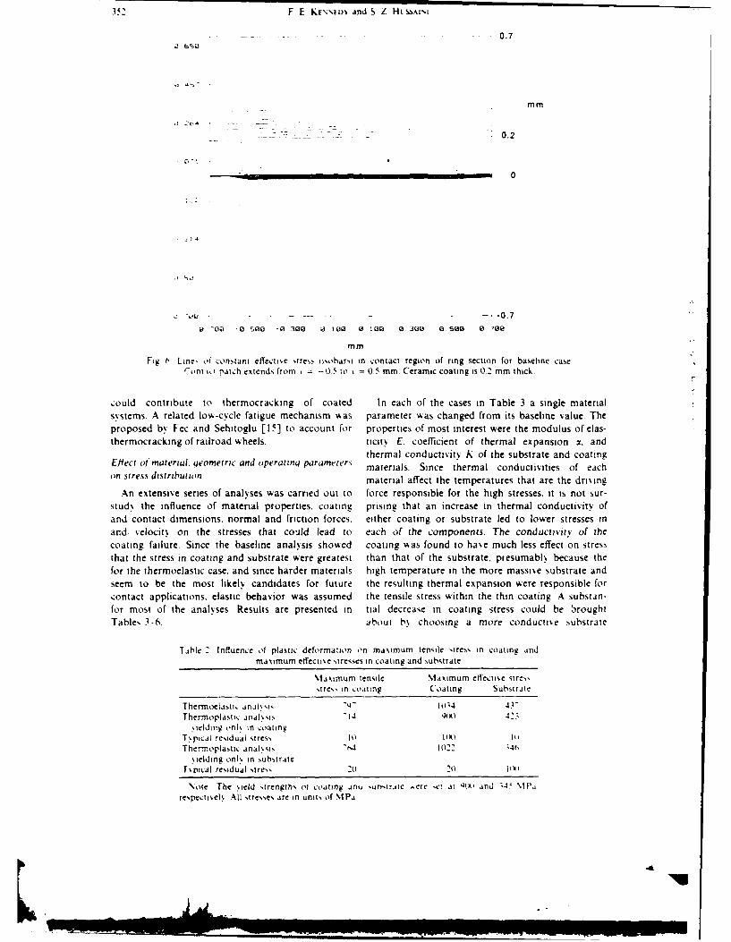
The results show, :2, Table I issumed purel\ ofIter substrate s'Wuld !sc he celastic deformaition Fhe etfectise i(%on \lisesi stress I racture duringz a sinkle contait tenc,,. \:!'' .7.)eiermined~ in that anai sis AsaN rather large in both contact spot mosed else%%here. hsse........c:oating and substrate. however. No some plastic be res idual stress at thc contac1't :Oc iton A., ' .rdetormation could he anticipated Figure 6 shows seen :n Tabie 2. !he residual ."tresh e isobars i lines of constant ctrectis e stressi for the would be tensile, hut it ss ould not tx aIz h toLj_
n)aseline thermoelastic case It :,an be seen that much cause coating failure b,, 1telf If o ' rtaict
,If 'he coating in the contact( ione had a high etfec- occurred at the samne !o,,itoon. !!,e %-'e ,!-2s tresN. s ith the peak etlect: e ste~in both tensile Stress s oul .iucrnent the t%- M,
tngand substrite o'ccurring near the point ot thermal and mnechanicai W'adin. 2 .5-
Mislmum contact temperature Thermal eirects ssere lihoo'd oI :cating t*ract. ii1s
i 'nd to be the nai 'r On trI kUtor to those high oc~urrences. rhus, in additio'nt'CtCts tresses and therefore wotild he !he dorrmn- tensile "t".ssdsuse nsC
352 F E KEN'NELw and S Z HLSSAIlI
.. 0.7
mm
- -- 0.2
0
J ",,u . . ... . .. .0.7
-0 ~ -13 500 -0 300 Id 100 0 108 0 300 a0500 02:08
mm
Fig 6 Line. if constant etTecftie stres, isoharsi in contact region of ring section for baseline caseC'ont i patch extends from = -0 5 to 0 5 mm Ceramic coating is 0.2 mm thick
,:ould contribute to thermocracking of coated In each of the cases in Table 3 a single materialsystems. A related low-cycle fatigue mechanism %%as parameter was changed from its baseline value. Theproposed by Fec and Sehitoglu [15] to account for properties of most interest were the modulus of elas-thermocracking of railroad wheels. tictty E. coefficient of thermal expansion 3. and
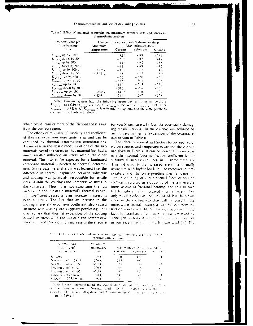
thermal conductivity K of the substrate and coatingEiect of material. qeomeri and iiperatn paramter. materials. Since thermal conductivities of eachon stress distribution material affect the temperatures that are the dri.ing
An extensive series of analyses was carried out to force responsible for the high stresses, it is not sur-study the influence of material propertes. coating prising that an increase in thermal conductivity ofand contact dimensions. normal and friction forces, either coating or substrate led to lower stresses inand. velocity on the stresses that could lead to each of the components. The conductivitv of thecoating failure. Since the baseline analysis show4ed coating was found to ha,,e much less effect on stres,that the stress in coating and substrate were greatest than that of the substrate, presumably because thefor the thermoelastic case. and since harder materials high temperature in the more massive substrate andseem to be the most likely candidates for future the resulting thermal expansion were responsible forcontact applications, elastic behavior was assumed the tensile stress within the thin coating A substan-for most of the analyses Results are presented in tial decrease in coating stress could be broughtTables 3-6. about b% choosing a more conducti.e substrate
Table ' Influence of plastic deformation on maximum tensile stress in coating andmaximum effectie stresses in coating and substrate
Maximum tensile Maximum effectiie sires,sires, in :oating Coating Substrale
Thermoelasti: analssi, N I14 41"
Thermoplastic analssis 1A 4,.23
ielding onl\ in :oatingT pical residual stress 0 lii) tlo
Thermoplastic analsis 1022 14t.,,ielding onls in substrate
T_,ptcal residual stress 2) 20 lwi
\ote The .eld strengths oi coating anu sunsirate ere ci at Qt and %1 lPa
respectielh, All stresses are in units of NIPa
• IlI U
Thermno- mechanical anaiysis of dry sliding systerns 353
Table 3 Effect of material properties on maximum temperatures and stresses-thermoelastic analysis
Proert~ changed Change in calculated ',alues ifrom ba~elinei'rm baseline Maximum Max. effectise tires
salue temperature Carbon Substrate Coaii
L do%%n by 50,, -1.4 '1 44-na Pby 100.--I 'K35Y ow n b 50 . 41 -i 4
K .up b% 100.2~ 35.K down by 50'', -34.8'. -5 -
Sup b% 100. 2 2E,,,downk5 b11 ii)
X-111 up b, 100. ,-54.,. .doA n by 50.-0, -'
K___ up y 10 -29.6', -14,0' -o I')K down 1 0 -45.91 --244 -26
Note' Baseline system had the following properties at room temperatureE.,,,,,, 14 GPa. )t._ = 4 E-6 C. Kz.o.,, = 10)\ MnK, L---,.-j.,)l') GPa.
=10 5 E .6 C. .. 11., 519 W inK. All s~stem, had the same Veometric,on iieura [ion. loads and %elocit .
which could transfer more of the frictional heat away Jor von Misesl stress. In fact. the potentiallk damav-from the contad. region. ing tensile stress T,, in the coating was reduced h%
The effects of modulus of elasticity and coefficient an increase in thermal expansion o1' the coatinz. asof thermal expansion were quite large and can be can be seen in Table 6.explained by thermal deformation considerations. The effects of normal and friction forces and %eloc-An increase in the elastic modulus of one of the two ihv on stresses and temperatures around the contactmaterials ra'sed the stress in that material but had a are giv~en in Table 4. It can be seen that an increasemuch smaller influence on stress within the other in either normal force or friction coefficient led tomaterial. This was to be expected for a laminated substantial increases in stress in all three material'composite material subjected to thermal deforma- This is due not to the increased ;tre,,s one normall%tion. In the baseline analysis it was learned that the associates with higher loads, but to increases in tem-difference in thermal expansion between substrate perature and the corresponding th ermal deforma-and coating was primarily responsible for tensile on. A doublingz of either normal lorce or friction,.tress. within the coating land compressive stress in coefficient resulted in a doublingz of the temperaturethe s;Ubstrate). Thus. it is not surprising that an increase due to frictional heatini!. aind that in turnincrease in the substrate material's thermal expan- led to sub'.tantiall, increas.ed thermal 'tre-.' Not'.ion coefficient caused a largze increase in stress in onI% was the etfecti'.e 'tress increa~ed. hut the tensiehoth materials The tact that an increase in the stress in the coatiniz skas drasticlI% affec:ted bs thecoating material's expansion coefficient also caused increased fric:tional hc,,tinc_. as can ,e een 7rlnAn increase in coating stress appears perplexing, until friction results in Table t) Fhi- ni'.iccn 'orKone realizes that thermial expansion of the coating fact that :rack;tte, of :oated 7:n,-, '.Sas 'caused an incrca~e :n the out-of-plane compressive Tribe [11)] in te'.i, it %er%.h~ r, 'r,ii ida. -At'tress T-,,. and this led to an increase in the effectise in our rcent !est, !t i -ke ' .cT' '-
I 'fet. 4I loads and %elocity on maxim am meat,.thermoelastic ii'
oad Maximum''cii temperature \tlasimam c .'c:~'1I
2.. C.. rise t'~ '
-::i, oef ) -0 C (
rn cc 26, oetf4=
35m 'ec a'C
\ 'te ties therA se noted, the joad. tr:tiin and o , :'
ti. a,,iel ine %'. iem No rmalI load - ;ix % ~ : I i s ..ci,;:' 4 1 m in, VI X .stems had the .ame m,iieri,1i ,r r'- C ,- rc
'tien :n fable I
354 F. E. KENNEDY and S. Z. HWssmLS
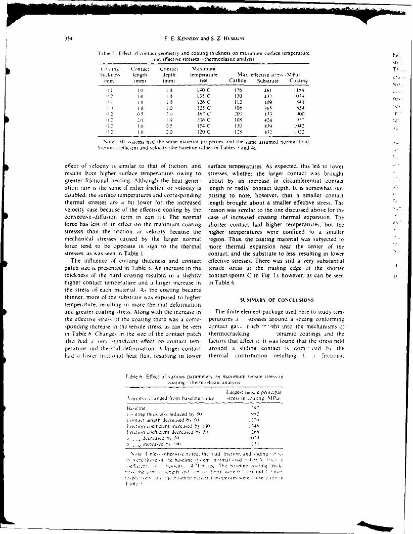
Tabie Effect of contact geometry and coating thickness on maximum surface temperature he-and effectie stresses-thermoelastic anal.ss tr.
t,.itng Contact Contact Maximum T-.thickne,s length depth temperature Max effectise st-'!,s iMPa,
mimi immi Immi rise Carbon Substrate Coating,
10 140 C 136 461 It'soli t 135 C 130 437 10,14 re,
4 0 1 0 126 C 112 409 840
1.0 1.0 125 C 106 365 6542 S 16" C 209 133 400 F"02 2.) 0 106 C 108 424 )-
02 I. 0.5 154 C 130 43,9 102.12 I o 2.0 120 C 12, 432 1022
\oie. -\I ,stems had the same material properties and the same assumed normal load.friction coefficient and elocitt ithe baseline values in Tables 3 and 4).
effect of xelocity is similar to that of friction, and surface temperatures. As expected. this led to lowerresults from higher surface temperatures owing to stresses, whether the larger contact was broughtgreater frictional heating. Although the heat gener- about by an increase in circumferential contactation rate is the same if either friction or velocity is length or radial contact depth. It is somewhat sur-doubled, the surface temperatures and corresponding prising to note, however, that a smaller contactthermal stresses are a bit lower for the increased length brought about a smaller effective stress. Thevelocity case because of the effectise cooling by the reason was similar to the one discussed above for theconsectiv e-diffusion term in eqn I1. The normal case of increased coating thermal expansion. Theforce has less of an effect on the maximum coating shorter contact had higher temperatures. but thestresses than the friction or velocity because the higher temperatures were confined to a smallermechanical stresses caused b. the larger normal region. Thus, the coating material was subjected toforce tend to be opposite in sign to the thermal more thermal expansion near the center of thestresses. as was seen in Table 1. contact, and the substrate to less, resulting in lower
The influence of coating thickness and contact effective stresses. There was still a very substantialpatch size is presented in Table 5. An increase in the tensile stress at the trailing edge of the shorterthickness of the hard coating resulted in a slightly contact ipoint C in Fig. I. however, as can be seen 0
higher contact temperature and a larger increase in in Table 6.the stress of each material As the coating becamethinner, more of the substrate swas exposed to higher SLMMARY OF CONCLISIONStemperature. resulting in more thermal deformationand greater coating stress. Along with the increase in The finite element package used here to studN ten-the effective stress of the coating there was a corre- peratures a stresses around a sliding conformingsponding increase in the tensile stress, as can be seen contact gas. .n.icb --- vht into the mechanisms ofin Table h. Changes in the size of the contact patch thermocracking ceramic coatings and thealso had .i ter ,inithcant effect on contact tem- factors that affect ai. It ',as found that the stress fieldperature and thermal deformation. A larger contact around a sliding contact is dom- oed b% thehad a lower frictional heat Hlux. resulting in lower thermal contribution resulting 1. a frictional
fable 0. Effect of %arious parameters on maximum tenNile stres, incoating - ihermoelastic analssis
Largest tenide principalSariL-. hanaed from haelhne %alue stress in coating AIPa
lb ,e=.:t e "'.1
itng thicknes reduced b% 50Contact length decreased b% -')friction coetticient increaed h% lix) 134hf ricttn .oefticient decrcaed h. 5 2i,
d ,..reased hs 0 I N-
i , ncrea'ed f,,% 1i11 111
\,,ie I nles otheri, h-wred, the load !ricton. and -id0nJ , .
z% %tec ihoe ihc baseline sssiem normai load =I \ ', :"~.et, ke 1nt . -' .eloIt N I m .ec The haejine o,,at:ne -
he ont.iut .c--!h .itd ni.it lepih Ae. e 2, 2 id I , P '1,:
,.'pte..,? .. and 'te 'a.et.'tt i.,tii, properies %%erC n'e ,'en !n
I ine
Thermo-mechanical analysis of dry sliding systems 355
heating. That contribution tends to cause tensile 3 V C Mow and H-. S. Cheng. Thermal stresses in anstresses in the coating, acting in the sliding direction. elastic half-space associated with an arbitrarily distrib-These tensile stresses could be large enough to cause uie 1 ear sore).nii ahPts.I.50
cracking of the .oatiniz. Although the tensile stresses 4. . H. Huang and F D Ju. Thermomechanical crackingwould be reduced by plastic deformation in either due to a mo'ing friction load. Wear 102.,51-4- 19x5)coating or substrate. such plastic deformation would 5. F D. Ju and T Ni Chen. Thermomechanical crackingresult in residual tensile stress in the coating. The in layered media from mouing friction load. 4SMfE Jresidual stress could lead to a low-cycle fatigue crack 6. ribofoq) 106. 513-518S l9i4i.
initatin b~ agmeting thethemomchaica F. E Kennedy and S A. Karpe. Thermocracking of ainiiaton agmetinz te termrnehancal mechanical face seal W1ear 79. 21-36i92tensile stress in the coating. To avoid this a harder -. A. %lishra and T Prasad. Residual stresses due to asubstrate material would be desirable. mo'.ing heat source hit J. .Aeh. Siz. 27. ;--s1
It w4as found that the stress in the coating could be 11985)S. F. E. KennedyN. J N. Grim and C K Chuah. -Xn
substantially reduced by operating at lower normal experimental theoreiical stud' of :ont a,: phenomenaload or lower %elocity. or by achiev~ing a lower fric- in mechanical face seal,. In Dei eirtorir \imwnr:, .L
tion coefficient. A reduction in coating stress could anid Etperimental Mtethods 4piied to Trth,,-,n Editedalso be achiexed by haxing a thicker coating or a b D Dowson et ali pp. 28-9.Butierworth,. L.on
coating with a lower modulus of elasticity or higher 9 F E.Kne% SZHsaniadB%1 tioathermal conductivity. An increase in coati ng thermal Contact condition and wkear of hard seal faces againsiexpansion coefficient would result in significantly carbon graphite. Luhrication Enqina iin press 1.lower tensile stress in the coating but more likeli- 10. F J. Tribe and G. A. Green. Assessment of mechanical
hood of plastic deformation. The properties of the seal face materials under controlled interface torquesubsrat proed o beat eastas mporantas tose II.Lubrication Enqnq 42. 686-693 I 19861.subtrae pove tobe t las asimprtat a thse IF. E. Kennedy. Surface temperatures in sliding
of the coating, with decreased coefficient of thermal ssstems-a finite element analysis. .AlWE J, Lzdrt a-expansion ior less difference between xsubitrm.c and tion Tec hnol. 103. 90-96 I 198 1Ii.
~ dcresed modlus of lasiciy, nd 12. F. E. Kennedy. F Colin. A. Floquet and R. Glovsk%.Improved techniques for finite element analvsis ofincreased thermal conductivity of the substrate sldn sufc teprue.InDil"et i
material leading to significant reductions in stress in Numnerical and Eviperimental Methods .4ppiied oT:both coating and substrate. holoqi iEdited by D. Dowson et af.) pp 3-5
Butierworibs. Lyon (1984).Acknov~led~jemnews-This hork was supported by, the Office 13, A. N. Brooks and T. J, R. Hughes. Streamline upwindof Naval Research contract no. N00014-81-K-0090. Dr Petro% Galerkin iormulations for consectine dominatedPeter J. Blau has been the ONR technical monitor. floASS Comput. %leth. appi Xlci I Enanq 32. 91 5
19821.14. K.-J Bathe and A Chaudhary. On finite element
analysis of large deformation frictional contact prob-REFERENCES lems. In t niricauoi w Ftirite Eiemneri kIXhthd' Edited
hy H Kardestunceri. pp 123-14- Elsevier. Am~terdamIF E. Kennedy,. Thermal and thermomnechanical effects N1
:n dry sliding. Wtear 100. 453-4"6 119841. 1M N C Fe,, i~nd H Sehitoglu. Thermal-mec:hanical2F F. Ling. 3uria, e Wtehanics5 John Wilev. New York damae in xiilroad wheels due to hot spoturic It,
l9~2 102. 3
Contact Conditions and Wear ofHard Seal Faces Against CarbonGraphite"F. E. KENNEDY, JR. (Member, STLE)S. Z. HUSSAINI and B. M. ESPINOZA VLE.436 6Thayer School of Engineering ; I .
Dartmouth CollegeHanover, NH 03755
The objectives of this work have been to gain a better under- bide. There are numerous forms and microstructures ofstanding of contact conditions at the interface between seal rings silicon carbide and the effects of those microstructural dif-
of mechanical face seals and to determine the influence of those ferences on friction (3), corrosion (3), and wear (4) have
conditions on wear of the seal components. Ring-on-ring sliding been investigated. It has been shown that silicon carbide
tests were run with two types of hard sealface materials, monolithic has good wear resistance, chemical inertness, and relativelysilicon carbide and metallic materials coated with eitoer tungsten low friction. As a result there has been increasing usage ofsilicon carbide seal rings but, as with most other monolithiccarbide or titanium nitride. In all tests the hard face ran against ceramics, there are problems with the fabrication and han-carbon graphite seal rings under dry conditions (no sealed fluid). dling of this brittle material. Less fragile forms of siliconThe total wear of the hard ring materials was very low in all cases, carbide are being developed, but they have not vet been
with sntered SiC rings and metallic rings coated with TiN having used in seals. One way to achieve a hard, wear-resistantthe lowest total wear. There was less wear of the carbon graphite surface without severe fabrication or handling problems is
rings when they were run against coated rings than when in contact to apply a hard coating to a ductile metallic substrate, andwith SiC. The friction coefficient was low (approximately 0.1) in one particular coating that has seen some use in seals is
all cases. tungsten carbide. Although the wear- and corrosion-resis-tance of WC coatings have been found inferior to siliconcarbide in some seal applications (2), (5), the coating usually
INTRODUCTION AND BACKGROUND outperforms metallic seal faces and warrants further study
Although sealed fluid is generally present in the thin leak- and development for severe service conditions. A different
age gap between the faces of "contact-type" mechanical seals, wear-resistant coating which has been used verv successfully
there is solid/solid contact between the seal rings (1). This in applications ranging from cutting tools to ball bearings,contact is augmented by thermal and mechanical distortion but has not vet seen use in commercial face seals, is titaniumof the rings. As a result of this solid/solid contact, seal ring nitride applied by a chemical or physical vapor depositionwear is one of the most important failure modes of me- process (6).chanical face seals, especially when operating conditions The approach used in this investigation of solid ceramics(pressures, loads, temperatures) are severe (2). To over- and ceramic coatings was one used in an earlier study ofcome the wear problem. a number of hard, wear-resistant the wear ot metallic seal rings (1. Because wear occurs onlyceramic seal ring materials have been developed and used, in the regions of actual solid/solid contact. it is desirable tooften in contact with a carbon-graphite seal ring. The ob- know how large those contact patches are, how the% arejective of this work has been to gain a better understanding distributed on the seal interface. what are the conditionsof the wear of solid ceramic and ceramic-coated metallic within the contact patches. and how those conditions relateseal rings in contact with carbon graphite and to determine to measured wear and friction. That information was ob-the solid/solid contact conditions responsible for that wear. tained in this study, as in the previous one. by means of a
One of the hardest and most wear resistant of the solid specially-designed contact probe (7). The probe enables ac-ceramics now being used in seal applications is silicon car- quisition of data about actual contact conditions during the
face seal operation. Since wear occurs only at solid contacts.and since an earlier study (1) had shown that the presence
Pveese at the 42nd Annual Meeting of a sealed fluid does not substantially alter the size ot theIn Anaheim. Callfornla
may 11-14, 1N7 solid/solid contacts, it was decided to run all tests dr%. i.e.Finul wanuecrit approved October 27, 19m6 without a sealed fluid.
... ...... . . E 361
EXPERIMENTAL binder and were applied by high velocity thermal spra%processes which produce dense, high quality coatings. The
ApparaItus first had 12 percent cobalt and was applied to a mild steel
The experiments were carried out on a converted 2-spin- substrate while the second had 14 percent cobalt and wasdie drill press. with each spindle driven by a separate 2 on a beryllium copper substrate. All tungsten carbide coat.horsepower motor. Normal load was applied through the ings were approximately 0.25 mm thick alter sprasing andspindles by static weights hung on the loading arm. Beneath slightly thinner after lapping.each spindle was a specimen-holding platform mounted on The titanium nitride coatings were applied b% a ph% sieala thrust bearing. Rotation of the specimen holders was lim- vapor deposition (PVD) process to previouslv-lapped be-ited by a torque-sensing system tor friction determination. rvlium copper substrates. Coating %as done b% means ot
All tests were run with a ring-on-ring specimen config- vacuum arc deposition at a coating temperature of 4S5-C.uration. Test rings of various materials, with a mean di- The TiN coatings were between 5 and 7 gin thick.ameter of approximately 5 cm. and a face width of at least All of the wear-resistant rings were tested against seal2.5 mm, were mounted in specimen holders on both the rings made from the same resin-impregnated grade of car-test platform and the end of the rotating spindle. The sta- bon graphite. Although it is usualk wise to cho se a gradetionary ring was made of carbon graphite and had a face of carbon graphite which is most compatible with the matingwidth of 2.5 mm and a shape typical of commercial seal ring material, it was decided to use a single grade in theserings. In some cases it had a very small (0.22 mm diameter) tests to eliminate a test variable.hole drilled in it, perpendicular to the contact surface. Afine (0.18 mm diameter) wire was inserted in the hole and Procedures
bonded in place with an electrically insulating epoxy ad- Before each test of a silicon carbide or tungsten carbide-hesive. prior to having its surface lapped and polished. The coated ring, the ring surface was hand lapped using a dia-wire then formed part of the ring surface, but it was elec- mond lapping/polishing compound (I Lm grit). The tita-tricaliv insulated from the rest of the ring. Operation of the nium nitride surfaces were not re-lapped after coating be-contact probe is described elsewhere (7). cause of their thinness. All rings, including the carbon
Weight measurements of the test rings before and after graphite rings, had their surface topography characterizedtests enabled determination of total wear of each ring. In- before each test using the computer-assisted profilometrvformation about wear at specified locations (within the con- system. The rings were washed in a non-abrasive cleanertact patches) and the interrelationship between wear and and then ultrasonically cleaned in ethanol and dried beforesurface profile was gained with the aid of a computer-as- being weighed on an analytical balance.
sisted stylus profilometrv system (1). Some linear profiles During a test the carbon graphite ring was mounted inwere taken in the radial direction, while other profiles were the stationary specimen, while the wear-resistant ring wascircumferential, with a high accuracy, motor-driven, air mounted on the rotating holder. Most tests were run at abearing rotary table being used to rotate the ring-shaped speed of 188.5 s-1 (1800 rpm). giving a sliding velocity ofspecimens beneath the profilometer's stationary stylus. A 4.7 m s- 1 although some tests of WC- or TiN-coated ringsreal-time data acquisition system was used to acquire and were also run at a sliding velocity of 3.1 m s- 1. A normaldigitize the surface profile data and to pass the data to a force of 100 N was applied to the rings in all tests. gi%ingdigital computer for analysis and plotting, a nominal pressure of 0.25 MPa between the contact faces.
The total sliding distance for most tests was 200 km. for a
Materials test duration of approximately 12 hours. For each materialcombination there were at least six tests ot 12 hour duration.Two monolithic ceramics were studied, both of the silicon alnwihoetslsig (hurSt)ktadsvrl
carbide family. The first was a commercial seal ring material, of shorter dration (17 ktin. The friction force as ad 0n-
reaction-sintered silicon carbide. Microscopic examination torer dontio n eac e. he con re as
revealed that the material had a mean SiC grain size of 10- used ocaionah during th tests o tall m rl e ap
15 g.m and contained about 15-20 percent free silicon. The r ned SiC to on the s i and m a iiln efet
second silicon carbide material was a sintered particulate regions of solid solid contact between the rings.
composite of silicon carbide and titanium di-boride. The Ae ion of a et the is
material contained about 20 weight percent TiB2., with both Ah rinausonia clea a die bhe rnd
SiC and TiB2 grains having a grain size in the range 2 to 5 wach rwe d oil theanl and he sit-
Lm. Although this new material has not vet been used in fac opgrah o hw agai caaced Vhe rIngface topography of each %%as again characterized. 1-he ring
face seal applications, it was chosen for this study because surfaces were examined using an optical iicrosope and.it has higher electrical conductivity than sintered or reac- in some cases. a scanning electron microscope.tion-bonded grades of silicon carbide. The improved con-
ductivity enabled use of our contact probe to study contactconditions at the carbon graphite/silicon carbide interface. RESULTS AND DISCUSSIONThe SiC + TiB2 material also has greater fracture tough-ness than many other grades of silicon carbide. Silicon Carbide
The ceramic coatings that were investigated were tung- The tests of reaction-sintered silicon carbide rings %%tcsten carbide and titanium nitride. ]Two different tungsten characterized by periods of smooth sliding punt tuated e vi %carbide coatings were studied, both of which had a cobalt 10 to 15 minutes by short bursts ot much higher trittl"1t
362 i in LURCAIN FN
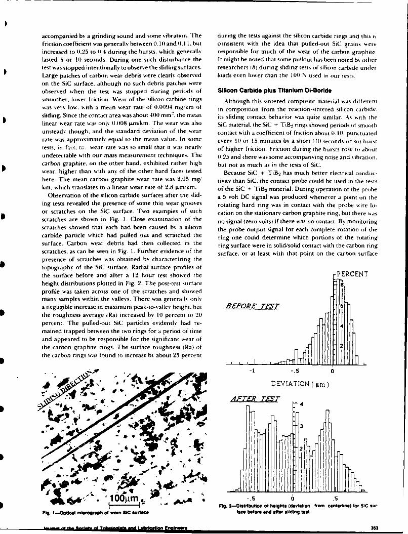
accompanied by a grinding sound and some vibration. The during the tests against the silicon carbide rings and this isfriction coefficient was generally between 0. IO and 0. 1. but consistent with the idea that pulled-out SiC grains sereincreased to 0.25 to 0.4 during the bursts, which generally responsible for much of the wear of the carbon graphite.lasted 5 or 10} seconds. During one such disturbance the It might be noted that some pullout has been noted b% othertest was stopped intentionally to observe the sliding surfaces. researchers (8) during sliding tests of silicon carbide underLarge patches of carbon wear debris were clearly observed loads even lower than the 100 N used in our tests.on the SiC surface, although no such debris patches wereobserved when the test was stopped during periods of Silicon Carbide plus Titanium 01-Boridesmoother, lower friction. Wear of the silicon carbide rings Although this sintered composite material %as different
was very low. with a mean wear rate of 0.0094 mg/km of in composition from the reaction-sintered silicon carbide.sliding. Since the contact area was about 400 mm 2. the mean its sliding contact behavior was quite similar. As with thelinear wear rate was only 0.008 i.mikm. The wear was also SiC material, the SiC + TiB2 rings showed periods of smoothunsteady though. and the standard deviation of the wear contact with a coefficient of friction about 0. 1.0. punctuatedrate was approximately equal to the mean value. In some every 10 or 15 minutes by a short (M0 seconds or sol bursttests, in fzct. tis wear rate was so small that it was nearly of higher friction. Friction during the bursts rose to aboutundetectable with our mass measurement techniques. The 0.25 and there was some accompanying noise and vibration.carbon graphite. on the other hand. exhibited rather high but not as much as in the tests of SiC.wear, higher than with any of the other hard faces tested Because SiC + TiB.2 has much better electrical conduc-here. The mean carbon graphite wear rate was 2.05 mg/ tivitv than SiC, the contact probe could be used in the testskm. which translates to a linear wear rate of 2.8 lxm/km. of the SiC + TiB2 material. During operation of the probe
Observation of the silicon carbide surfaces after the slid- a 5 volt DC signal was produced whenever a point on theing tests revealed the presence of some thin wear grooves rotating hard ring was in contact with the probe wire lo-or scratches on the SiC surface. Two examples of such cation on the stationary carbon graphite ring, but there %,asscratches are shown in Fig. I. Close examination of the no signal (zero volts) if there was no contact. By monitoringscratches showed that each had been caused by a silicon the probe output signal for each complete rotation of thecarbide particle which had pulled out and scratched the ring one could determine which portions of the rotatingsurface. Carbon wear debris had then collected in the ring surface were in solid/solid contact with the carbon ringscratches, as can be seen in Fig. I. Further evidence of the surface, or at least with that point on the carbon surfacepresence of scratches was obtained by characterizing thetopography of the SiC surface. Radial surface profiles ofthe surface before and after a 12 hour test showed the PERCENTheight distributions plotted in Fig. 2. The post-test surfaceprofile was taken across one of the scratches and showedmany samples within the valleys. There was generalls onlya negligible increase in maximum peak-to-vallev height. but BLFOR TAYT 6
the roughness average (Ra) increased by 10 percent to 20percent. The pulled-out SiC particles evidently had re-mained trapped between the two rings for a period of timeand appeared to be responsible for the significant wear ofthe carbon graphite rings. The surface roughness (Ra) ofthe carbon rings was found to increase by about 25 percent
DEVIATION ( jtmn)
SATER AE .54
was 3
2
..,, , ~. . | ..
... , .; .* .j~ ,,,,I
1i00A .5 .5V Fig. 2-Distributon of height* (deviation from certerlne) for SIC sur-
Fig. 1--Opticai microgruph of worn SIC surface face before and after sliding test.
nineera 363
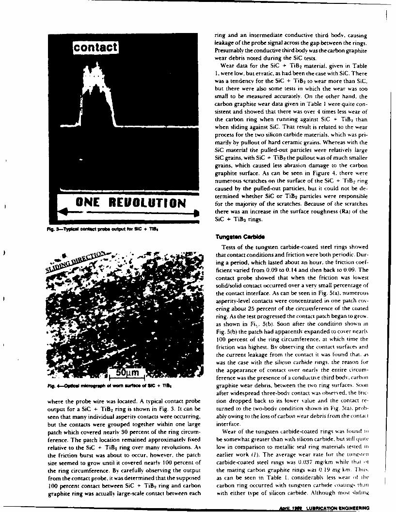
ring and an intermediate conductive third body. causingleakage of the probe signal across the gap between the rings.
o tct Presumably the conductive third body was the carbon graphitewear debris noted during the SiC tests.
Wear data for the SiC + TiB2 material, given in Table1, were low, but erratic, as had been the case with SiC. Therewas a tendency for the SiC + TiB2 to wear more than SiC.
but there were also some tests in which the wear was too
small to be measured accurately. On the other hand. the
carbon graphite wear data given in Table I were quite con-sistent and showed that there was over 4 times less wear of
the carbon ring when running against SiC + TiB2 than
when sliding against SiC. That result is related to the wearprocess for the two silicon carbide materials, which was pri-marily by pullout of hard ceramic grains. Whereas with theSiC material the pulled-out particles were relatively largeSiC grains, with SiC + TiB2 the pullout was of much smaller
grains, which caused less abrasion damage to the carbon
graphite surface. As can be seen in Figure 4. there werenumerous scratches on the surface of the SiC + TiB2 ringcaused by the pulled-out particles, but it could not be de-termined whether SiC or TiB2 particles were responsible
ONE REUOLUTION for the majority of the scratches. Because of the scratches_* there was an increase in the surface roughness (Ral of the
SiC + TiB2 rings.
ft. 3-Typic cteec probe outpurt for SIC + T1
Tungsten Carbide
Tests of the tungsten carbide-coated steel rings showedAo ,that contact conditions and friction were both periodic. Dur-
ing a period, which lasted about an hour. the friction coef-1ficient varied from 0.09 to 0.14 and then back to 0.09. The
- ~ contact probe showed that when the friction was lowestsolid/solid contact occurred over a very small percentage ofthe contact interface. As can be seen in Fig. 5(a). numerousasperity-level contacts were concentrated in one patch co%-ering about 23 percent of the circumference of the coated
ring. As the test progressed the contact patch began to grow.as shown in Fit. 5(b). Soon after the condition shown in
ow Fig. 5(b) the patch had apparently expanded to cover neark100 percent of the ring circumference, at which time the
friction was highest. By observing the contact surfaces and
the current leakage from the contact it was found that. aswas the case with the silicon carbide rings, the reason forthe appearance of contact over nearly the entire circum-ference was the presence of a conductive third body. carbon
ig. 4-4pca mlcroeapl of worsu rlace of SIC + Tis graphite wear debris, between the two ring surfaces. Soon
after widespread three-body contact was observed, the tric-
where the probe wire was located. A typical contact probe tion dropped back to its lower value and the contact re-
output for a SiC + TiB2 ring is shown in Fig. 3. It can be turned to the two-body condition shown in Fig. 5(a). prob-
seen that many individual asperity contacts were occurring, ably owing to the loss of carbon wear debris from the conthct
but the contacts were grouped together within one large interface.
patch which covered nearly 30 percent of the ring circum- Wear of the tungsten carbide-coated rings was found U)
ference. The patch location remained approximately fixed be somewhat greater than with silicon carbide, but still qUit
relative to the SiC + TiB2 ring over many revolutions. As low in comparison to metallic seal ring materials tested in
the friction burst was about to occur, however, the patch earlier work (1). The average wear rate for the tUn1114cIt
size seemed to grow until it covered nearly 100 percent of carbide-coated steel rings was 0.037 mg/km while that ,,t
the ring circumference. By carefully observing the output the mating carbon graphite rings was 0.19 mg km. Yhu,.
from the contact probe, it was determined that the supposed as can be seen in Table I. considerabls less wear of the
100 percent contact between SiC + TiB2 ring and carbon carbon ring occurred with tungsten carbide coatmg, thani
graphite ring was actually large-scale contact between each with either type of silicon carbide. Although most slhditig
pDH . IM LUBRICATION ENGINEERING
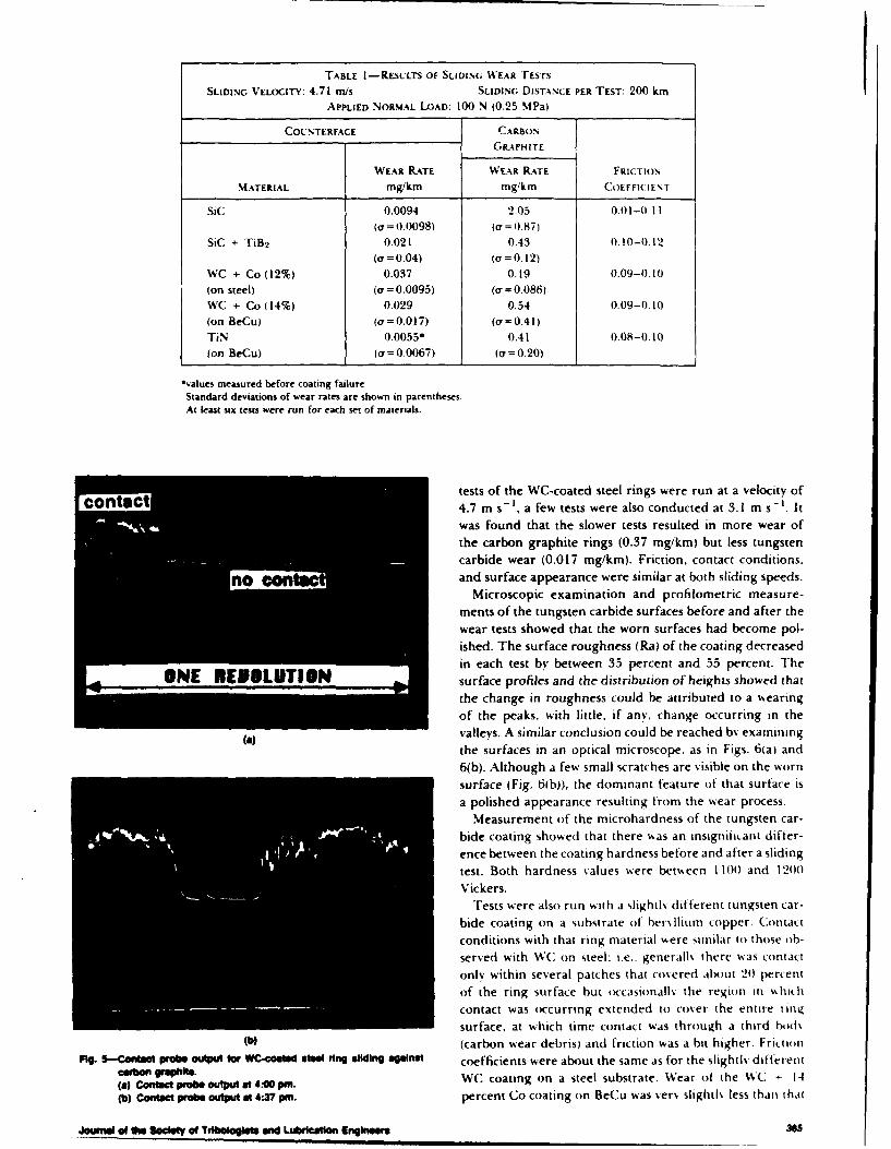
TABLE 1-RESULTS OF SLIDING WEAR TESTS
SLIDING VELOCITY: 4.71 rn/s SLIDING DISTANCE PER TEST: 200 kmAPPLIED NORMAL LOAD: 100 N (0.25 MPa)
COUNTERFACE CARBON
GRAPHITE
WEAR RATE WEAR RATE FRICTION
MATERIAL mg/km mg/km COEFFICIENT
SiC 0.0094 2.05 0.01-0. 11(o = 0.0098) (e = 0.87)
SiC + TiB2 0.021 0.43 0.10-0.12(g = 0.04) () = 0,12)
WC + Co (12%) 0.037 0.19 0.09-0.10(on steel) (a = 0.0095) (a = 0.086)WC + Co (14%) 0.029 0.54 0.09-0.10
(on BeCu) (a'=0.017) (a=0,41)TiN 0.0055* 0.41 0.08-0.10
fon BeCu) ( = 0.0067) (cr=0.20)
*values measured before coating failure
Standard deviations of wear rates are shown in parentheses.At least six tests were run for each set of materials.
ia tests of the WC-coated steel rings were run at a velocity of
4.7 m s-i, a few tests were also conducted at 3.1 m s- I. Itwas found that the slower tests resulted in more wear of
the carbon graphite rings (0.37 mg/km) but less tungstencarbide wear (0.017 mg/kin). Friction, contact conditions,
no Oand surface appearance were similar at both sliding speeds.Microscopic examination and profilometric measure-
ments of the tungsten carbide surfaces before and after thewear tests showed that the worn surfaces had become pol-
ished. The surface roughness (Ra) of the coating decreasedin each test by between 35 percent and 55 percent. The
ONE KEOLUTIGN surface profiles and the distribution of heights showed thatthe change in roughness could be attributed to a wearingof the peaks, with little, if any, change occurring in the
(a) valleys. A similar conclusion could be reached bv examiningthe surfaces in an optical microscope. as in Figs. 6(ai and6(b). Although a few small scratches are visible on the wornsurface (Fig. 6(b)). the dominant feature of that surface isa polished appearance resulting from the wear process.
Measurement of the microhardness of the tungsten car-bide coating showed that there Aas an insigniiant differ-ence between the coating hardness before and after a sliding
test. Both hardness values were between 1100 and 1200
Vickers.Tests were also run with a slightls different tungsten car-
bide coating on a substrate of her% Ilium copper. Contactconditions with that ring material %%ere similar to those ob-served with WC on steel: i.e., generall% there was contactonly within several patches that covered about 24) percent
of the ring surface but o(casionallv the region in Ahihcontact was occurring extended to cover the entire ringsurface, at which time contact was through a third ho)ds
(b) (carbon wear debris) and friction was a bit higher. FritIoM
Mg. 5-Contacti probe output for WC-conlll stal ring sllIdng aplnat coefficients were about the same as for the slightlv different
(a) Contactprobe outputat4si. WC coating on a steel substrate. Wear of the WC + 14
(b) Contact probe output at 4:? pmn. percent Co coating on BeCu was verN slightl% less than that
Jounal of Ow1 Ia of TdIbeloglete and Lubrication Engl 36
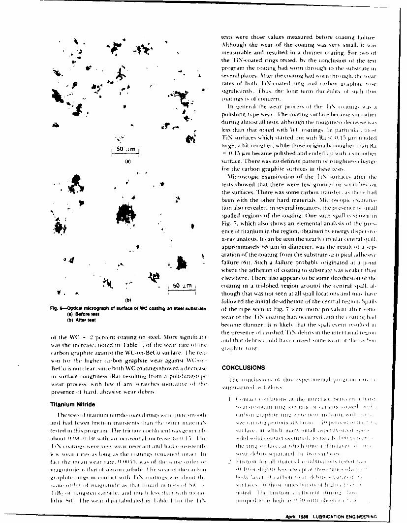
tests were those %allues measured before coatinig taihtire
Although the wear of the coating was verN small. it %,a,
~ measurable and resulted in a thinner coating For two ofthe TiN-coatedl rings tested. hs, the conclusion of the test
V I . , program the coating had worn thro(Lgh to the substrate titL se~eral places. After the coating had %%irn ihr tgh. dlie va
9 rates of' both FiN-coated ring and .,irhon i Ylphlli 14osesigniitan tl v. [-hus. the long termn tlirabhit (1 of u( thin
coating IS Of1 concern.In genecral the w~ear pn it e-,s (f the IN .\ tug i ,is
polishing-ti, pe wear. The c.oatingy surfn c be anit sim ti herdur rng Almiost all tests. AhLrh itgh thIe I migh tes ,Ic I case%,Iless than that noted with W(. ciatings. Ini pairthiulai. i-TiN surfac-es which started out with Ra < 015 Ti ni tendle
50 mto get a hit to ugher. while those originallo, ii tugher lati1 Ra50I , m 015 wn became polished ant endeld Ll p ii h tI e
(a) Surface. There was no definite pattern of rouighness haigefor the carbon graphite surfaces in these tests.
Microscopic examination oh the 1 IN surf esC atf retilte
4 V tests showed that there were few grixties r) t~ rio Tlies -itthe surfaces. There was some carbon tratisfet. .1 1s lI t IM(Itbeen with the other hard materials. MI i iil ttti ii
tion also revealed, in several instances, the ptoesent (d Nf111i.114 1 :spatted regions of the coating. One such spill i, Ahi os\ ii IiFig. 7. which also shows an elemental anal, Sis of the pits-ence of titanium in the region. iobtained ho. energ\ dtispetsts t
e ~x-ray anaivsis. It can be seen the nearloi t- rular tetral "pall.* approximatey 65 I.m in diameter, was the result oft .1 qe
aration of the coating from the substrate ia t% pit al adi(Iheiv
failure (6ji. Such a failure prohabl, (originated at .I P4,11i14___ where the adhesion of coating to substrate %%as %weaker thati
elsewhere. There also appears to be some decohesion oft Tle
,50JIa!M coating in a tn-lobed region arounld the enttral spall. At-1. though that was not seen at all spal1 locations atnd Ina hake
(b) followed the initial dc-adhesion of the central regil n. SpahlsFig. 6-Optical micrograph of surface of WC coating oni steel substrata of the tope seen in Fig. 7 were more pre, aleni after sotItI,
(a) Before test wear of the FIN ooatnig had OILcctlrredh and the (ailit'.z litvl(b) After teat
becomec Thinner. It is likels that the pat~ll veml riilIt1 III
of thre WAC - 2 percent co~ating on steel. More signitioarit tioe ihatn~, ikihisheol i\ doedri stilt iteitvt ~ie iiwas the inTrease. noted in Table 1. of the wear rate ofl the-ta tbi (i ac asdoicel- 1(
arbitti graiphite agaitit the WC-on-BeCu surface. Fhe tea-son for the higher 1 arbon graphite wear against W
Bei is not ( leir. stlte hot h WC coatings show ed 1 (let rease CONCLUSIONSiii surface rotigh-ness 4Rit resultiti front .I fihf4-' le o Iil,- , it 11is tApiA11VIA iieiia pI1 ilk i
wear process. with few% ift ati% siratches itilitiict '1 Tileiiitr/i i l
presence of hlard, abrasive wear debris.I ( ii . i Talii. its (iIlic t t c tak iii Iii
Titanium Nitride str*tsoii Ui. lttt ii (*Ittit(-1M(-( .inI.
I he tests 'if titantini nliride-, o),Ited rI I II N r (It I it csrii' nih -1 ,1 h'. it _,I '.ilf. I ii1 't c t- it'' ti-i it-i Ill. Ill, '
aiid had fe',ser frititipti transietsriii lian tiliei iiiictiiiicm, iiitii~pi'ti fl i~ I tit
Apriltc 1118 L%010T1O ENllEEa
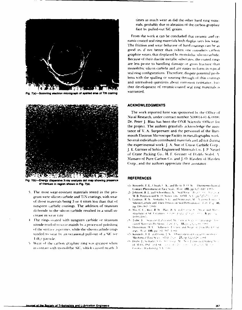
times as much wear as did the other hard ring miate-rials, probably due to abrasion of the carbon graphiteface bfy pulled-out SiC grains.
From the work it can be concluded that ceramic and ce-ramic-coated seal ring materials both displas .er% lo%% %%ear.The friction and wear behavior of hard coatings can he asgood as. if not better than (%hen fine roimiders (arbon
graphite wear), that displa~ ed h% monolitit sito ')it aride.Because of their ductile metallic stubstrates, the coated ritivsare less prone to handling damage for gross trature thanmonolithic silicon carbide and are easier to form in It% pit .lseal ring configurations. Therefore, despite potential piirb-lems with the spalling or w4earing through of thincotoz
I and unresolved questions about corrosion resistante. I Ar-
., ter developmient of' ceramic-coated seal ring materials -
Fig. 7(a)-Scanning electron micrograph of Wpalled area of TIN aoting wratd
-. . ACKNOWLEDGMENTS
The work reported here was sponsored b% the Of fife tofNaval Research, under contract number N0001I4-8 I - K-i 19)).
Dr. Peter J. Blau has been the ()NR Scientific Offiitrothe project. The authors grateftill% ac.kno%%fedge the assis-tance of V. A. Surprenant and the personnel of the Dart-mouth Electron Microscope Facilit% in metallographic work.Several individuals contributed materials and ad,.ice dlUrin.4the experimental work: J. A. Sue of Unioni Carbide Corp.J. E. Garnierof Sohio Engineered Materials Co.. 1. P Netiz-lof' Crane Packing Co., H. F. G;reiner of FN &( ScAlo. .\Massaro of Pure Carbon Co. and]J. 0. Ha\,den of Ha~rleiC:orp.,- and the authors appreciate their assistance.
--- 1 - ,.- - ... REFERENCESFig. 7(b)-Energy dispersive X-ray analysis dot map showing presence
of titanium In region shown in Fig. 7(s). 1) Knned%. F. E.. ( huali. I Is, and tir-,t 1r.- (1 1% 1hrcr rrr. Irrre -
(.onta~ Phenrrmenau in Fati: e tcai. li -"1' 102. pp 1 -7-1I4'11
3. The mnost wear-resistant materials tested in the pro- 12) )hiron. R I., jrid shht-r 1% Sct %%ear 71 .,....*. H.
gram were silicon carbide and TIN coatings. with wear \.1 B Pett-rsmi trd I,% () k\WI mvid \N\iF \ )q 7_,77,-, [.ash'a\ R 1% , t-ehair1 (.. arnd sfawr.,'.r \1 \ tvi.-of those materials being 3 or 4 times less than that of1 )Iidrmn t.jrhid- arnd I 11Crr t t' C(rrSC PV'tI..i ir n, rri I - 40).
tungsten L.arhide coatings. The addition of titanium pp .t56_113 JIlflI
di-boride to the silicon carbide resulted in a small in- .41 too :f . kl. e, R \% ,t Rif B mI, I, \i )
.rease in %%eat* rate. , I)n I I4. [he rings (,otied sm th tungsten carbide for titaniuni 5, 1 1M. F c"',,c ..If,'! M. I:, . ! -d I~
nitride tcrirlrIl to) I%-.r mnainli b,, .i process 1)1 polishing I ,c Vi.11- 1A, 11r. j'ci 39 p: ,~ -9 .
off the Niii tiii r i~r ties. %%hile the siliclon carbide Iinigs 1. nt- 100. H E W1-1
tended to) %%vat b\ .in foccasional pull-out Of a Si( Oit 7 1Kt-rrrck. f F .. IA -In. I fr 'ic..it'r I, "I .,Ii
I IB,. pl).iile %feharnrr~r fa, vsc.U, .1 1.- 27. pp1-.~'
I. % oait the (arhonit raphite ring .%is greatest %%ent \i . / 0 . . .
Ini r ood( ill th mnlitim SiC. '.%hi It (aitoct itceail 5 %.'z.i~ -rr
-Iii-rdo h "syo rgisIts and Lubrication Engineers 367
THERMOCRACKING AND WEAR OF CERAMIC-COATED FACE SEALS
FOR SALT WATER APPLICATIONS
Francis E. Kennedy, Jr. (Member STLE), Beda M. Espinoza and Susanne M. Pepper
Thayer School of Engineering
Dartmouth College
Hanover, NH 03755
ABSTRACT
The objectives of this investigation were to better understand the tribological
behavior of ceramic- or cermet-coated mechanical face seal rings sliding against
carbon graphite and the thermocracking that occurs with some of the ceramic coatings.
Sliding wear tests were conducted on Inconel 625 seal rings coated with four different
hard materials: chromium oxide, chromium carbide, titanium nitride, and tungsten
carbide. Tests were also run to determine the corrosion behavior of the ceramic-
coated rings in seawater. Surface profilometry, mass loss measurements, and
microscopy were used to characterize wear, cracking and corrosion phenomena.
Coupled with the experimentation was a theoretical analysis of temperatures and
stresses in the contact region of the ceramic coating during sliding. The influence of
various material and geometric parameters on coating cracking was studied in the
analytical work.
Presented at STLE Annual Meeting, Cleveland, Ohio, May 11, 1988
Kennedy and Espinoza Page 1
INTRODUCTION
The seal rings of mechanical face seals must be able to withstand many hours of
continuous sliding contact during operation. The wear that occurs during that contact
frequently determines the useful life of a seal ring. Seal designers have attempted to
increase seal durability by choosing hard, wear-resistant seal ring materials. Ceramic
materials, such as silicon carbide, have proven to be good candidates for many severe
seal conditions because of their high hardness and good wear resistance [1]. Most
ceramics are somewhat difficult to form in the shapes and sizes required for large face
seals, however, and their brittleness necessitates great care in handling and mounting.
There is interest in achieving the wear resistance of ceramics without the production and
handling difficulties associated with monolithic ceramics. One way to do so is to use
ceramic or ceramic/metallic (cermet) coatings on a readily-formed, ductile metallic
substrate. Ceramic-coated seal rings have met with success in many applications, but
their use in salt water seals has been limited. Problems that could lead to foreshortened
lives of ceramic-coated seal rings include spalling [3] and thermocracking [4] of the
ceramic coatings. Another problem has been corrosion in the salt water environment,
particularly crevice corrosion at the coating/substrate interface [2].
Despite these potential problems, ceramic coatings are of interest in mechanical face
seals because they have been shown to have nearly as good wear resistance as
monolithic ceramics in seal configurations [3]. The coatings in that study were on
substrates of either iron- or copper-based materials. Tribe [2] showed, however, that
ceramic coatings on those substrates can experience pitting or crevice corrosion in salt
water. There was little evidence of corrosion, though, for the same coatings on a substrate
of corrosion-resistant Inconel 625 [2]. That nickel-based alloy is now being used
successfully in many marine components that require good resistance to corrosion in
seawater, including some components of face seals. For that reason, this project
concentrated on the study of several promising ceramic coatings on Inconel 625
substrates. Of particular interest were the tribological performance of the coatings in
sliding contact against carbon graphite seal rings, the failure mechanisms that could limit
the usefulness of the coatings, and the corrosion resistance of the coating/substrate
system.
Four different coatings were studied. They included chromium oxide, chromium
Kennedy and Espinoza Page 2
carbide, titanium nitride and tungsten carbide. The four coating materials are among the
most effective hard coatings developed in recent years and are used for a variety of
tribological applications [5]. Several boride coatings were also tested, but they proved to
wear excessively in initial tests and were not tested completely. The goal of the project
was an improved understanding of the factors influencing wear, thermocracking and other
mechanisms of coating failure. To achieve this goal, the project consisted of both
experimental and numerical activities.
EXPERIMENTAL
Materials
The substrate for all of the coated rings tested in this study was Inconel 625, a nickel-
based alloy with proven corrosion resistance. Tribe's work on ceramic coatings exposed
to a seawater environment had previously shown that this substrate material was not
corrosively attacked, unlike steel substrates [2]. The major components of the material are
nickel (61%), chromium (21.5%) and molybdenum (9%). The material was machined to a
ring shape with 5.5 cm outside diameter, 4 cm inside diameter and 6 to 7 mm thickness.
Prior to being coated the rings were degreased, ultrasonically cleaned, and sputter
cleaned. The rings were then coated with one of four different hard coatings, tungsten
carbide (WC), chromium oxide (Cr 20 3), chromium carbide (a mixture of Cr7C3 and Cr3C2)
or titanium nitride (TiN).
The chrome oxide coating was applied by plasma spraying on a pre-roughened
surface. No bond coat was used and micrographs of the interface showed that mechanical
interlocking was the predominant means of bonding between coating and substrate.
Cross-sections revealed that the coating thickness was 350 - 375 rIm. The coated
surfaces were lapped and polished to a surface roughness of about 0.11im Ra.
Two slightly different chromium carbide coatings were tested. Both coatings had the
same chemical composition, consisting of 80% chromium carbide (92 Cr - 8 C) and 20%
nickel chromium (80 Ni - 20 Cr). The only difference between the two coatings was the
size distribution of the nickel chromium particles, -44 lim for one coating, designated C,
Kennedy and Espinoza Page 3
and -20 ILm for the other, designated H. Both coatings were applied by the detonation gun
thermal spray process and had an as-sprayed thickness of about 250 g~m. The coatings
were lapped and polished to a roughness of Ra _ 0.1 pgm prior to the wear tests. A recent
study of the same two chromium carbide coatings by Sue and Tucker [7] showed that the
coating with the smaller nickel chromium particle size, coating H, had more resistance to
erosion by solid particles over a large range of temperatures. They also found that coating
C was slightly more dense and harder than coating H. There does not appear to have
been a comparison of the sliding wear behavior of the two chromium carbide coatings
prior to this investigation, at least not in a seal configuration.
The tungsten carbide coatings were also applied by a plasma spray process. The
sprayed powder included a nickel and cobalt binder, in addition to WC. To further promote
the formation of a metallurgical bond between coating and substrate, the coated rings
were heat treated after spraying. During the heat treatment, diffusion between the 250 lum
thick coating and the nickel-based substrate resulted in a diffusion layer as is shown in
Figure 1. No distinct interface between coating and substrate could be noted, in contrast to
the chromium carbide and chromium oxide coatings. The coated surface was lapped and
polished after heat treatment to a 0.1 gm Ra roughness.
The titanium nitride coatings were applied by a physical vapor deposition (PVD)
process (vacuum arc evaporation) at a coating temperature of slightly less than 5000C.
The ring surfaces were lapped flat before being polished. The PVD process is slow and is
normally used to produce very thin coatings [5]. Earlier tests [3] had shown that seal rings
with thin (5 p.m or less) TiN coatings did not have good long-term durability. For that
reason, thicker TiN coatings were used in this study. First a thin bond coat of pure titanium
was deposited on the lapped Inconel 625 surface, and this was followed by a 5gm thick
layer of TiN. The coated surface was then sputter cleaned and another thin titanium bond
coat was applied, followed by a 20lim thick titanium nitride layer, resulting ir. a 25um total
thickness of the TiN coating.
In all tribotests, the coated rings were slid against a commercial seal ring made from
a resin-impregnated grade of carbon graphite. The same grade of carbon graphite was
used throughout the test program.
Properties of all materials used in the test program are given in Table 1.
Kennedy and Espinoza Page 4
Trbotest Methods
The tribotests were carried out on a test machine previously used for both wear
studies and face seal research (3]. The machine is a converted drill press, with each of two
test spindles being driven by a separate motor. The spindles were gear driven at a preset
speed of 1800 rpm for this work. A normal load of either 50N or 1 OON was applied through
the spindles by static weights hung on the loading arm. A ceramic-coated seal ring was
mounted at the end of the rotating spindle. Beneath each spindle was a specimen-holding
platform mounted on a thrust bearing. A stationary seal ring was mounted in that
specimen holder. Rotation of the specimen holder was limited by a torque-sensing system
for continuous measurement of friction.
The stationary specimen was a commercial seal ring made of carbon graphite. It had
a mean diameter of 5 cm and a face width of 2.5 mm, and those dimensions dictated the
nominal contact area between the seal faces. The rotating ceramic-coated ring had a
slightly greater face width and was mounted concentric with the stationary ring. With these
ring dimensions, the sliding velocity at the contact interface was 4.7 m/s and the nominal
contact pressure was 0.25 MPa for the 1 0ON load cases and 0.125 MPa with a 50N load.
Prior to testing, the contacting faces of most rings were hand lapped and polished,
with alumina grit being used for the carbon graphite ring and diamond lapping/polishing
compound for the hard coatings. Some of the coated rings (those coated with TiN) were
not re-lapped because of the coating thinness. The surface topography of each ring was
characterized using a computer-assisted profilometry system. The test specimens were
ultrasonically cleaned and weighed on an accurate analytical balance both before and
after each test.
All tests were run dry (no sealed fluid) and at room temperature. The tests were not
meant to simulate the performance of an ideal seal, which would have a thin layer of
sealed fluid between the flat seal faces. In actual seals it is known that there is some
contact between the solid seal faces and this solid/solid contact is responsible for wear of
the seal rings [3]. These tests were meant to determine the tribological behavior of the
seal rings under this solid/solid contact.
Most tests were run for either 6 or 12 hours, giving a total sliding distance of 100 km
or 200 kin, respectively. For each material there were 6 tests of 12 hour duration or 12
tests of 6 hour duration, alona with one test lasting 30 hours for a sliding distance of 500
Kennedy and Espinoza Page 5
km. The friction force was monitored continuously during each test. At the conclusion of a
test the seal was disassembled and each ring was ultra- sonically cleaned and dried
before being re-weighed on the analytical balance. The surface topography was again
characterized and the ring surfaces were examined using optical and scanning electron
microscopy.
Corrosion Test Methods
For the corrosion tests, coated rings of each material were cut into sections of
approximately 1 cm length. Both worn and unworn rings were sectioned. One cross-
sectional face of each specimen was ground and polished and the specimens were then
cleaned and accurately weighed. Each was placed in a salt water solution representative
of seawater and the solution was agitated by means of a magnetic stirrer. The containers
were sealed to prevent evaporation and were left at room temperature for 30 and 60 day
periods. The specimens were then dried and re-weighed and viewed in optical and
scanning electron microscopes to look for evidence of corrosion, particularly at the
coating/substrate interface and on the friction surface.
Results of Tribotests
The four coating materials studied intensively in this series of tests all showed very
low wear rates, comparable in magnitude to the wear rates measured earlier for similar
coatings on different substrates and almost as low as the wear of silicon carbide measured
in the earlier study [3]. A summary of the wear data is given in Table 2.
Comparison of the results for the tests of tungsten carbide coatings shows that wear
of both coating and carbon graphite faces was approximately proportional to normal load.
Wear rates at 1 OON load were almost double those measured at 50N load. If it can be
assumed that each of the coatings would show a similar load dependence, it can be
concluded that the chromium carbide coatings exhibited the lowest wear (mass loss) rates
of any of the coatings tested in this study. On a volume loss basis, the wear rates of
tungsten carbide and chromium carbide were appoximately equal, with the other two
coating materials having higher volumetric wear.
The carbon graphite wear rate was generally about 50 times greater than the wear
rates of the coatings, but in all cases it was less than had been measured in tests of
Kennedy and Espinoza Page 6
reaction-sintered silicon carbide rings [3]. Slightly more carbon graphite wear occurred in
the tungsten carbide tests than with the other three coating materials. Even after
correcting for the effect of load on wear, the carbon graphite wear against the chromium
carbide materials was less than against the other coating materials, with TiN being a close
second in that respect.
There was no major difference noted in the friction coefficient for the different coating
materials. In all cases the friction coefficient was at or slightly below 0.10. As had been
found in the earlier study, there were occasional bursts of higher friction. The buildup of
third body wear debris appeared to be responsible for the friction bursts.
Each of the coating materials showed its own peculiarities and they will be discussed
separately.
.Tungsten Carbide The wear process for the tungsten carbide coatings
appeared to begin with wear of the metallic binder, causing the carbide particles to
protrude slightly from the surface. The carbides then wore slowly by a polishing process,
resulting in flat carbide particles, as is seen in Figure 2. The result of this process was a
decrease in the surface roughness of the carbide coating (from an initial average of about
0.15 gm Ra to about 0.10 gm Ra). The rings had been heat treated after coating, causing
a metallurgical bond to form between coating and substrate. This is in contrast to the
mechanical bond usually formed between plasma-sprayed coatings and substrate. This
heat treatment had no detrimental, and perhaps even a beneficial, effect on the wear of the
coating, and the composition of the substrate seemed to have little effect. The wear rates
measured in this study were found to be slightly lower than the wear of some un-heat
treated tungsten carbide coatings on the same substrate [8] or on different substrates [3].
There was no evidence of any debonding or cracking for the WC coatings in this study,
although there was some microscopic pitting on the contact surface. The pits were fewer
in number with the heat treated coating than with other tungsten carbide coatings [8].
Some of the pits appeared to be originally pores in the coating, while others may have
been the result of fatigue, resulting in the removal of one or more carbide particles. The
liberated particles could then have remained as third bodies between the sliding surfaces,
contributing to the wear of the carbon graphite ring surface.
Titanium Nitride The TiN coatings were found to wear by polishing of the
surface asperities (burnishing), resulting in a decrease in surface Dughness during the
Kennedy and Espinoza Page 7
first few hours of testing. A thin, discontinuous transfer film of carbon was also formed on
the coating surface during the first few hours of testing. There was some evidence of light
abrasion of the carbon graphite surface by small third body particles (presumably TiN wear
debris), but the wear was small until later stages of testing, when the TiN coating had worn
very thin. Evidence of the decrease of coating thickness due to wear is shown in Figure 3.
Wearthrough of the coating resulted in a sharp increase in wear of both ceramic-coated
ring and carbon graphite surface. Data are given in Table 2 which show that the TiN wear
rate increased by about two orders of magnitude when coating failure occurred, and the
carbon graphite wear increased almost as much. The cause of the increased wear rates
was the presence of hard TiN debris between the two sliding surfaces. There was
evidence that spalling of the TiN coating had occurred when the coating became very thin.
This spalling had also been noted in earlier tests of thinner TiN coatings on different
substrates (3]. The wear rate for the thicker coatings used in this study was similar to that
for thin TiN coatings, and therefore they lasted longer than the thin coatings, but they still
suffered from significantly increased wear rates when wearthrough did occur.
C Plasma-sprayed Cr20 3 coatings also had very low wear
rates, even a bit lower than TiN, and they also appeared to wear by a process of polishing
of surface asperities, resulting in a slight (about 10%) decrease in surface roughness (Ra).
There was little evidence of abrasion by the Cr 20 3 coating. The friction coefficient was a
bit higher than was measured with either TiN or WC, but was still only approximately 0.10.
Despite the good wear behavior of Cr20 3 , there was still a durability problem; in this case,
thermocracking. Radial cracks were observed in the wear track on the coating surface
after sliding tests, and one example is shown in Figure 4. A cross-section of a typical crack
is shown in Figure 5. Since the cracks were wider at the top than near the substrate
interface (Figure 5), they appeared to be surface originated. The deepest cracks were
blunted at the coating/substrate interface. Similar thermocracks had been observed in
seawater- lubricated seals by Tribe and Green [4]. The cracks could limit the durability of
the surfaces because small chips of coating material could be liberated at the edges of the
cracks. This could lead to more three-body abrasion by the debris and more abrasive
wear of the carbon graphite surface by the crack edges, although there was little evidence
of such damage in these tests at 100 N normal load. Several tests were also run at a
I Kennedy and Espinoza Page 8
higher load (750 N) and it was found that the number and size of thermocracks was
considerably larger at the higher load. There was also some evidence of abrasion of thecarbon graphite surface by debris from the cracks at the higher load. A thermomechanical
analysis was carded out to help explain the cause of the cracking (below).
Chromium Carbide Both of the chromium carbide coatings showed good
wear resistance in these tests. On a volumetric basis their wear rates were about equal
that of tungsten carbide, but on a mass loss basis the chromium carbide coatings proved
superior to all the other coatings. Wear of the carbon graphite rings sliding against
chromium carbide was no greater than against any of the other coatings. Coating H, which
had the smaller nickel chromium particle size and slightly lower density, had slightly more
wear resistance than coating C (on a mass loss basis), and also caused less carbon
graphite wear. Coating H had also proven to have more erosion resistance than coating C
in tests by Sue and Tucker [7].
Examination of the worn surfaces of both chromium carbide coatings showed that
wear had been by a light polishing mechanism. Evidence of this is shown in Figure 6,
which is a scanning electron micrograph of a worn C coating. The light phase is the nickel
chromium binder, which is considerably softer than the gray carbides. As can be seen in
Figure 6, the softer binder wore more readily than the carbides and receded a bit from the
carbide surface. Some carbon wear debris was found collected in the small depressions
caused by binder wear (Figure 6). The binder phase in the H coating was found to be
more evenly dispersed than in the C coating, resulting in more of a marbling appearance.
The uniformity and better dispersion of the smaller binder particles in the H coating may
have been responsible for the lower wear observed with that coating. The wear grooves
on the surface of both carbide coatings were shallow, indicating that there were no large
abrasive third body particles in the interface. This indicates that there was little pullout of
carbide particles. More evidence for that conclusion and for the conclusion that wear was
by a polishing mode was found by looking at surface profiles of the coatings before and
after the sliding tests. It was found that there was no increase in either number or depth of
the grooves on the surface, but there was some wear of the asperity peaks. This resulted
in a small decrease in surface roughness (from about 0.074m to 0.054m Ra in a typical
case). The very gradual wear of the peaks, most of which are chromium carbide particles,
would result in the production of very fine wear debris, a conclusion that is consistent with
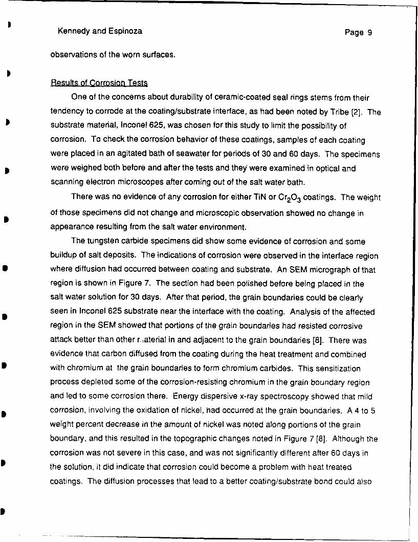
Kennedy and Espinoza Page 9
observations of the worn surfaces.
Results of Corrosion Tests
One of the concerns about durability of ceramic-coated seal rings stems from their
tendency to corrode at the coating/substrate interface, as had been noted by Tribe [2]. The
substrate material, Inconel 625, was chosen for this study to limit the possibility of
corrosion. To check the corrosion behavior of these coatings, samples of each coating
were placed in an agitated bath of seawater for periods of 30 and 60 days. The specimens
were weighed both before and after the tests and they were examined in optical and
scanning electron microscopes after coming out of the salt water bath.
There was no evidence of any corrosion for either TiN or Cr 20 3 coatings. The weight
of those specimens did not change and microscopic observation showed no change in
appearance resulting from the salt water environment.
The tungsten carbide specimens did show some evidence of corrosion and some
buildup of salt deposits. The indications of corrosion were observed in the interface region
where diffusion had occurred between coating and substrate. An SEM micrograph of that
region is shown in Figure 7. The section had been polished before being placed in the
salt water solution for 30 days. After that period, the grain boundaries could be clearly
seen in Inconel 625 substrate near the interface with the coating. Analysis of the affected
region in the SEM showed that portions of the grain boundaries had resisted corrosive
attack better than other r, aterial in and adjacent to the grain boundaries (8]. There was
evidence that carbon diffused from the coating during the heat treatment and combined
with chromium at the grain boundaries to form chromium carbides. This sensitization
process depleted some of the corrosion-resisting chromium in the grain boundary region
and led to some corrosion there. Energy dispersive x-ray spectroscopy showed that mild
corrosion, involving the oxidation of nickel, had occurred at the grain boundaries. A 4 to 5
weight percent decrease in the amount of nickel was noted along portions of the grain
boundary, and this resulted in the topographic changes noted in Figure 7 [8]. Although the
corrosion was not severe in this case, and was not significantly different after 60 days in
the solution, it did indicate that corrosion could become a problem with heat treated
coatings. The diffusion processes that lead to a better coating/substrate bond could also
Kennedy and Espinoza Page 10
result in a lessening of the corrosion resistance at the coating/substrate interface by
sensitization of the Inconel 625 material.
A very small mass loss was noted for specimens of both chromium carbide coatings
after the corrosion tests. They were the only materials for which a mass loss was found,
but the total mass loss for each of those specimens (on the order of 1 mg for the thirty day
test) was miniscule. Examination of the exposed interface after a test showed no evidence
of any corrosion, with the only defects being voids that had been present before the
corrosion test (Figure 8). There is some potential for crevice corrosion with the nickel-
containing alloy, although the presence of a large amount of chromium and its oxides
should obstruct the corrosion mechanism and protect the material from significant
corrosion damage [8].
ANALYTICALMethods
The most problematic coating failure mechanism observed in the experimental work
was the thermocracking noted with Cr 20 3 coatings. In an attempt to understand the
reasons for that cracking, an analytical study of thermal and thermo- mechanical
phenomena near the sliding contacts was carried out. The analysis was done using finite
element methods which are described in detail elsewhere [6]. The primary components of
the analysis were a determination of the temperature distribution in the sliding contact
region and an analysis of the stresses and deformations caused by that temperature
distribution, along with mechanical normal and tangential tractions. The temperatures
were calculated using a finite element thermal analysis program, Thermap, that was
developed especially to analyze the effects of frictional heating of sliding contacts.
Thermo-elastic stress analyses were done using the Adina finite element program. A suite
of interconnected programs was developed to automatically generate the finite element
mesh, generate the boundary condition files, run Thermap and Adina, and plot the output
[6].
Boundary conditions for the finite element analysis were determined from the
experiments described earlier. Measured values of friction force, along with the applied
Kennedy and Espinoza Page 11
normal load and sliding velocity, were input to the analysis programs. The normal forcewas assumed to be uniformly distributed along the top surface of the Inconel 625 ring and
the friction force was assumed to be applied along a transverse cross-section of that ring.
The carbon graphite ring was assumed to be supported on a rigid support and to have its
rotation restrained by rigid anti-rotation slots. Thermocouples had been placed on the
back (non- contacting) faces of both seal rings in the sliding tests and the measured
steady-state temperatures (1000 to 1500C) were prescribed on the finite element model at
the appropriate locations. All boundary conditions are shown schematically in Figure 9.
The geometry of the rings used in the finite element model was similar to the
geometry of the test seal rings. Earlier work [3] had shown that the rings are in actual solid/
solid contact only over a portion of their circumference. For this analysis it was assumed
that contact occurred in five spots equidistantly spaced along the ring surface. It was
assumed that all contact spots was identical and that a typical contact length was 1 mm.Only one such spot was analyzed, as is shown in Figure 9. These assumptions were
based on measurements of contact sizes for WC-coated rings sliding against carbongraphite, wion the measurements having been made using a unique contact probe [3].
A two dimensionsal finite element mesh was generated for the typical contact case andthat mesh was stretched or shrunk to fit other contact lengths. The mesh had very small
elements in the contact region to accurately model temperature and stress gradients there.Frictional heat was assumed to be uniformly distributed among the elements along the
length of the contact. The rate of frictional heating was determined from measured friction
force and velocity values.
Results
Temperatures and stresses were analyzed for three of the four coatings tested in the
experimental program and for several different values of coating thickness and contact
length [9]. The maximum temperature for all material combinations occurred on the
contact surface in the trailing portion of the contact zone. Temperature gradients were
greatest in the contact region, particularly in the coating. Cr20 3 , which has the lowest
thermal conductivity of the three coatings studied, had the highest maximum surface
Kennedy and Espinoza Page 12
temperature and the largest temperature gradients. For example, for a coating thickness of
250 lam, a contact length of 1 mm, and a normal load of 20 N per contact, the maximum
surface temperature for the chrome oxide coating was 3430C, while for titanium nitride and
tungsten carbide the maximum surface temperatures were 206 and 1980C, respectively.
Surface temperature predictions for some of the Cr20 3 coatings studied are shown in
Table 3. It can be seen that contact length had a significant influence on maximum surface
temperature, owing to the fact that frictional heat flux increased with a decrease in contact
length. The influence of coating thickness was a bit less significant. An increase in
thickness of the chrome oxide coating led to an increase in temperature, but that effect was
not noted with coatings with higher thermal conductivity, such as tungsten carbide. For
those more conductive coatings, an increase in coating thickness led to a slight decrease
in surface temperature. An even more important factor proved to be load per contact. If the
normal load increased, or the number of contact spots decreased, the frictional heat flux
would increase, resulting in higher surface temperatures.
Stresses in the contact region included contributions from both mechanical tractions
and temperature gradients. In the cases studied, where the sliding velocity was high
enough to cause significant frictional heat generation and temperature gradients, the
thermal contribution proved to be dominant [9]. For this coating/substrate combination, the
coefficient of thermal expansion of the substrate was nearly twice as large as that of the
coating (Table 1). The result of this was a state of stress that was predominantly tensile in
the coating and compressive in the adjacent substrate. The stresses were decreased
slightly by an increase in coating thickness, even though the surface temperature was
increased. This was because for thicker coatings more of the frictional heat stayed in the
coating and the substrate remained cooler. Thus, there was less differential thermal
expansion between substrate and coating and, as a result, less thermal stress in the
system.
The largest tensile stress in the coating occurred at the contact surface near the
trailing edge of the contact (point C in Figure 9). The magnitude of that tensile stress was
significantly affected by both the length of a contact spot and and the normal load per
contact spot, as can be seen in Table 3. Therefore, factors that led to an increase in contact
pressure and frictional heat generation rate caused higher surface temperature and also
Kennedy and Espinoza Page 13
had the greatest effect on tensile stress in the coating. That tensile stress could become
large enough to cause a crack to form and propagate in the coating. The largest tensile
stress component was found to act in the circumferential direction and occurred near the
contact surface. Thus it is to be expected that any cracks resulting from that state of stress
would be radial and would be surface originated. This is in agreement with the crack
orientation observed in the experimental work described above.
CONCLUSIONS
Each of the coatings tested in this program, tungsten carbide, titanium nitride and
chrome oxide, all on Inconel 625 substrates, had low wear rates and low friction during
sliding against carbon graphite seal rings. The wear rates were lower than for metallic
seal face materials and nearly as low as had been determined for monolithic silicon
carbide. Despite the good friction and wear results, most of the coatings displayed a
deficiency which could limit their durability in salt water sealing applications.
Owing to the slow nature of the PVD coating process, titanium nitride coatings have a
limited thickness. Although they have low wear rates when the coating is intact, the wear
is finite and eventually the coatings get quite thin. When this happens there is a tendency
for the coatings to spall and this results in a very significant increase in wear rate, owing to
the presence of hard, abrasive third bodies between the seal faces.
Tungsten carbide coatings show evidence of some surface pitting resulting from both
initial porosity and the occasional spalling of a carbide particle from the surface. The
amount of pitting can be reduced and the bond strength of the coating/substrate interface
can be increased by heat treating the coated rings. Diffusion processes during the heat
treatment can reduce the resistance of the Inconel 625 substrate to corrosion in salt water
by sensitizing the material at the grain boundaries in the region adjacent to the coating.
The chromium carbide coatings displayed the lowest wear rates of all the coatings
tested. Wear of the carbon graphite in contact with the chromium carbide rings was also
less than or equal to that measured with the other coatings. The chromium carbide coating
with the smaller nickel chromium particle size (coating H) showed even better wear
Kennedy and Espinoza Page 14
resistance than did the other chromium carbide coating tested. Neither of the chromium
carbide coatings showed any evidence of thermocracking in the tribotests, and they
showed very slight mass losses in the corrosion tests.
Although chrome oxide coatings have good wear resistance, they show a tendency
to thermocrack. The cracks originate on the sliding surface and are oriented perpendicular
to the sliding direction. The severity of thermocracks increases with increases in norma;
load.
Thermal and stress analyses of the contact region of coated rings showed that
frictional heating causes surface temperature increases which can result in tensile stress
in the coatings. The surface temperatures and resulting tensile thermal stress are higher if
the coating has a low thermal conductivity and a large difference between coefficient of
thermal expansion of coating and substrate, as is the case with chrome oxide. The highest
tensile stress acts in the sliding direction and occurs at the sliding surface. Thus, that
stress is probably responsible for the thermocracking observed with chrome oxide
coatings in this test program.
Kennedy and Espinoza Page 15
ACKNOWLEDGEMENTS
The work reported here was supported by the Office of Naval Research through
Contract N0001 4-87-K-01 25. Dr. A.W. Ruff was the ONR Scientific Officer. The authors
gratefully acknowledge the assistance of Ms. Louisa Howard of the Dartmouth Electron
Microscope Facility with SEM and EDS analysis. Materials for the test program were
contributed by Union Carbide Corporation and EG&G Sealol. Their contributions were
greatly appreciated, as was the helpful advice of Dr. J.A. Sue of Union Carbide Corp.
REFERENCES
1. White, E.B. and Karpe, S.A., "Evaluation of Mechanical Face Seal Materials",
Lubrication Engineering, v. 41 (1985), 675-680
2. Tribe, F.J., "Seawater-Lubricated Mechanical Seals and Bearings: Associated
Materials Problems", Lubrication Engineering, v. 39 (19831, 292-299
3. Kennedy, F.E., Hussaini, S.Z. and Espinoza, B.M., "Contact Conditions and Wear of
Hard Seal Faces Against Carbon Graphite", Lubrication Engineering, v. 44 (1988),
361-367
4. Tribe, F.J. and Green, G.A., "Assessment of Mechanical Seal Face Materials Under
Controlled Interface Torque", Lubrication Engineering, v. 42 (1986), 686-693
5. Ramalingam, S., "New Coating Technologies for Tribological Applications", in M.B.
Peterson, ed., Wear Control Handbook, ASME, New York (1981), 385-411
6. Kennedy, F.E. and Hussaini, S.Z., "Thermomechanical Analysis of Dry Sliding
Systems", Computers and Structures, v. 26 (1987), 345-355
Kennedy and Espinoza Page 16
7. Sue, J.A. and Tucker, R.C., "High Temperature Erosion Behavior of Tungsten- and
Chromium-Carbide-Based Coatings", Surface and Coatings Technology, v. 32 (1987),
237-248
8. Pepper, S.M., "An Investigation into the Wear of Ceramic Coated Mechanical Face
Seals", Master of Engineering Thesis, Thayer School of Engineering, Dartmouth College,
January 1989.
9. Espinoza, B.M.M., "Investigating the Failure of Ceramic Coatings for Mechanical
Face Seal Applications", Master of Engineering Thesis, Thayer School of Engineering,
Dartmouth College, April 1987.
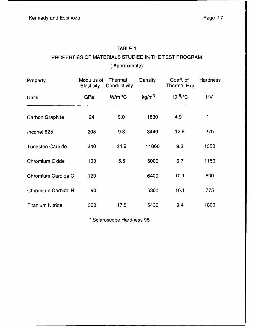
Kennedy and Espinoza Page 17
TABLE 1
PROPERTIES OF MATERIALS STUDIED IN THE TEST PROGRAM
(Approximate)
Property Modulus of Thermal Density Coeff. of HardnessElasticity Conductivity Thermal Exp.
Units GPa W/m 0C kg/m 3 10-6/0C HV
Carbon Graphite 24 9.0 1830 4.9
Inconel 625 208 9.8 8440 12.8 270
Tungsten Carbide 240 34.6 11000 9.3 1050
Chromium Oxide 103 5.5 5000 6.7 1150
Chromium Carbide C 120 6400 10.1 800
Chromium Carbide H 90 6300 10.1 775
Titanium Nitride 300 17.0 5430 9.4 1800
* Scleroscope Hardness 95
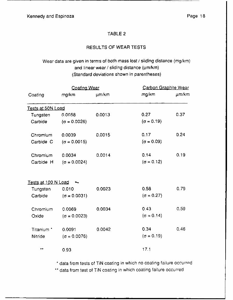
Kennedy and Espinoza Page 18
TABLE 2
RESULTS OF WEAR TESTS
Wear data are given in terms of both mass lost / sliding distance (mg/km)
and linear wear / sliding distance (4m/km)(Standard deviations shown in parentheses)
Coating Wear Carbon Graphite Wear
Coating mg/km rim/km mg/km pm/km
Tests at 50N Load
Tungsten 0.0058 0.0013 0.27 0.37
Carbide (a = 0.0026) (a = 0.19)
Chromium 0.0039 0.0015 0.17 0.24
Carbide C (o = 0.0015) (a = 0.09)
Chromium 0.0034 0.0014 0.14 0.19
Carbide H (Y = 0.0024) (a= 0.12)
Tests at 100 N Load -
Tungsten 0,010 0.0023 0.58 0.79
Carbide (a = 0.0031) (a = 0.27)
Chromium 0.0069 0.0034 0.43 0.59
Oxide (a = 0.0023) (a = 0.14)
Titanium * 0.0091 0.0042 0.34 0.46
Nitride (a = 0.0076) (a = 0.19)
S* 0.93 17.1
* data from tests of TiN coating in which no coating failure occurrpd
•* data from test of TiN coating in which coating failure occurred

Kennedy and Espinoza Page 19
TABLE 3
4b TEMPERATURE AND STRESS IN CHROME OXIDE COATED RING
Effect of various operating and geometric parameters on maximum surface temperatureand maximum tensile stress in coating and maximum effective (von Mises) stress inInconel 625 substrate. Thermoelastic analysis.
Coating thickness (mm) 0.125 0.25 0.25 0.50 0.25
Contact length (mm) 1.0 1.0 0.25 1.0 1.0
Normal load per contact spot (N) 20 20 20 20 100
Maximum surface temperature (°C) 329 343 489 355 1233
Maximum principal stress in coating (Mpa) 169 166 235 151 525
Maximum effective stress in substrate (MPa) 501 460 461 407 1362
Kennedy and Espinoza Page 20
FIGURE CAPTIONS
FIGURE 1. Cross-section of plasma-sprayed and heat treated tungsten carbide coating
on Inconel 625 substrate.
FIGURE 2. Worn surface of tungsten carbide coating surface.
FIGURE 3. Cross-sections of titanium nitride coating outside wear track (left), at edge of
wear track (center), and at center of wear track (right).
FIGURE 4. Worn surface of chromium oxide coating, showing radial crack.
FIGURE 5. Cross-section of crack in chromium oxide coating. Coating surface is at left,
coating/substrate interface is at right.
FIGURE 6. Worn surface of chromium carbide C coating, showing softer Ni-Cr binder
matrix (lighter color) receding from the harder carbide phase (gray)
FIGURE 7. Cross-section of tungsten carbide - coated specimen after 30 days in salt
water solution. Photograph shows substrate region approximately 300 p.m
beneath worn surface, with coating interface off photo at left and bulk of
substrate at right.
FIGURE 8. Optical micrograph of chromium carbide H coating on Inconel 625 substrate
after 60 days in NaCI bath.
FIGURE 9. Diagram of region modelled in finite element analysis, showing boundary
conditions applied.
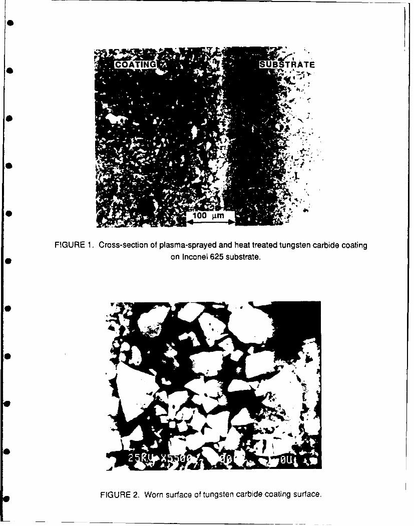
COTING UBSTRATE
100m
FIGURE 1. Cross-section of plasma-sprayed and heat treated tungsten carbide coatingon Inconel 625 substrate.
F.PIa
FIGURE 2. Worn surface of tungsten carbide coating surface.
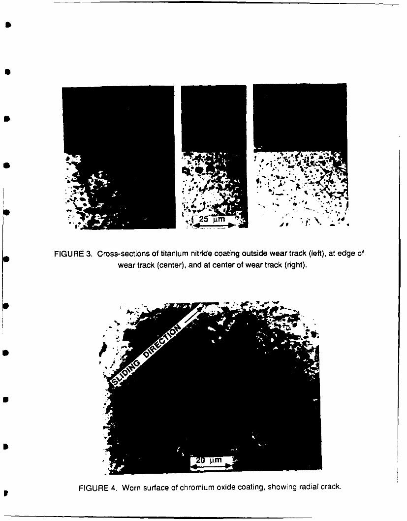
"6
•f.2 .m ..> . -, a
FIGURE 3. Cross-sections of titanium nitride coating outside wear track (left), at edge ofwear track (center), and at center of wear track (right).
FIGURE 4. Worn surface of chromium oxide coating, showing radial crack.
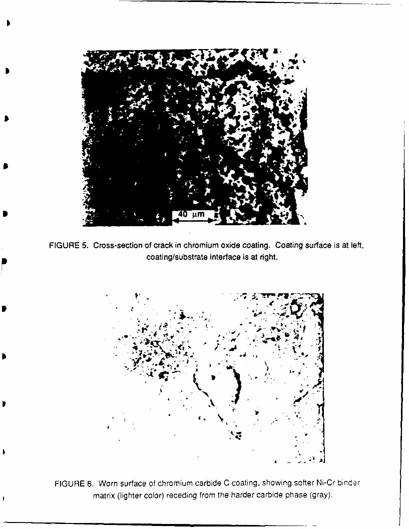
FIGURE 5. Cross-section of crack in chromium oxide coating. Coating surface is at left,coati ng/subst rate interface is at right.
.I.
U k
,!,
FIGURE 6. Worn surface of chromium carbide C coating, showing softer Ni-Cr binder
matrix (lighter color) receding from the harder carbide phase (gray).
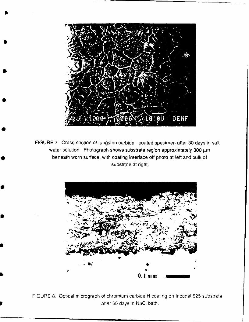
FIGURE 7. Cross-section of tungsten carbide - coated specimen after 30 days in saltwater solution. Photograph shows substrate region approximately 300 p4m
beneath worn surface, with coating interface off photo at left and bulk of
substrate at right.
00
.:..4
VA V
1 0.1Imm
FIGURE 8. Optical micrograph of chromium carbide H coating on Inconel 625 substrate
after 60 days in NaCl bath.
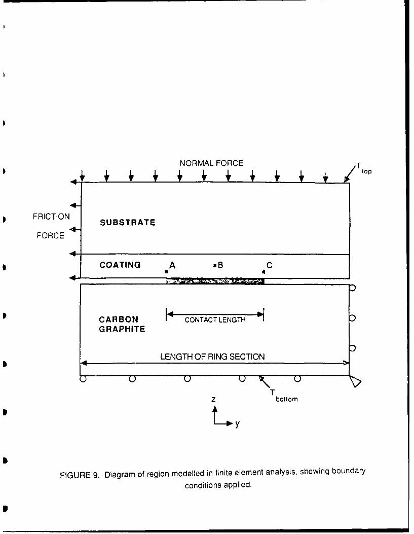
NORMAL FORCE T
FRICTION SUBSTRATE
FORCE
1 COATING A ,B C
4.
CARBON I CONTACT LENGTHGRAPHITE
LENGTH OF RING SECTION
U UU Q
TTbottom
Y
FIGURE 9. Diagram of region modelled in finite element analysis, showing boundary
conditions applied.
, I l r u nli l nm N
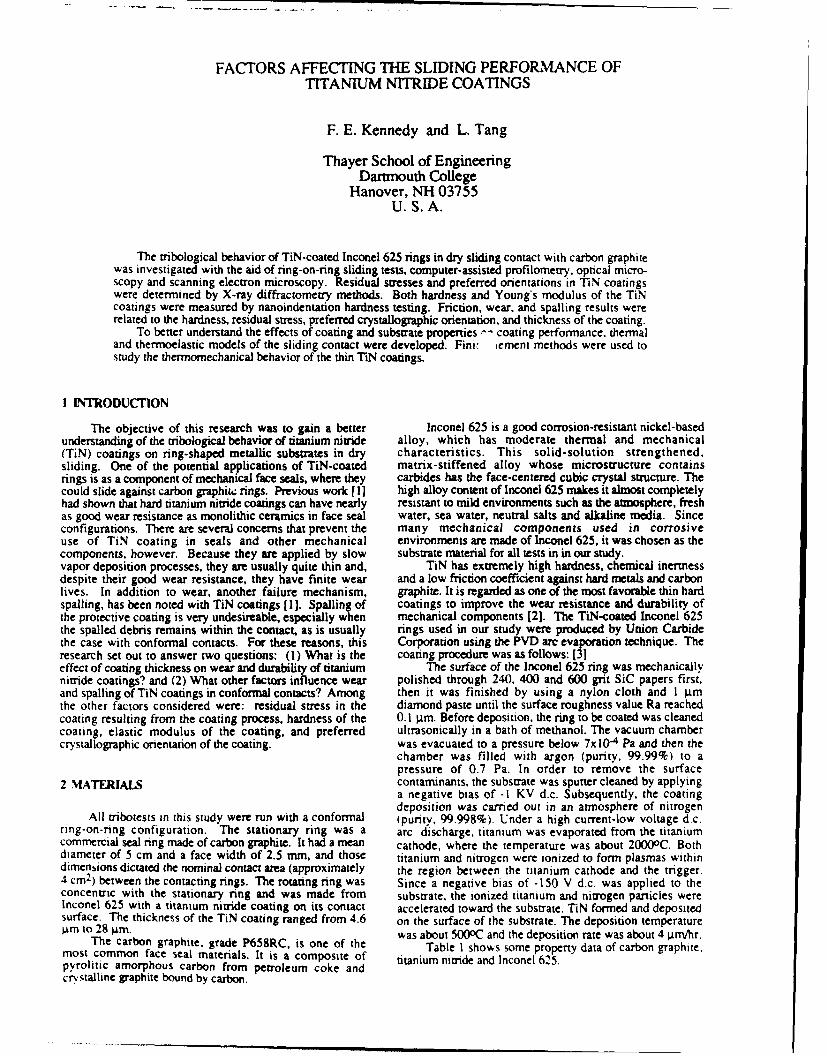
FACTORS AFFECTING THE SLIDING PERFORMANCE OFTITANIUM NITRIDE COATINGS
F. E. Kennedy and L. Tang
Thayer School of EngineeringDarmouth College
Hanover, NH 03755U.S.A.
The tribological behavior of TiN-coated Inconel 625 rings in dry sliding contact with carbon graphitewas investigated with the aid of ring-on-ring sliding tests, computer-assisted profilometry, optical micro-scopy and scanning electron microscopy. Residual stresses and preferred orientations in TiN coatingswere determined by X-ray diffractometry methods. Both hardness and Young's modulus of the TiNcoatings were measured by nanoindentation hardness testing. Friction, wear, and spalling results wererelated to the hardness, residual stress, preferred crystallographic orientation, and thickness of the coating.
To better understand the effects of coating and substrate properties -- coating performance, thermaland thermoelastic models of the sliding contact were developed. Fini: ement methods were used tostudy the thermomechanica behavior of the thin TiN coatings.
I INTRODUCTION
The objective of this research was to gain a better Inconel 625 is a good corrosion-resistant nickel-basedunderstanding of the tribological behavior of titanium nitride alloy, which has moderate thermal and mechanical(TiN) coatings on ring-shaped metallic substrates in dry characteristics. This solid-solution strengthened,sliding. One of the potential applications of TiN-coated matrix-stiffened alloy whose microstructure containsrings is as a component of mechanical face seals, where they carbides has the face-centered cubic crystal structure. Thecould slide against carbon graphite rings. Previous work [l] high alloy content of Inconel 625 makes it almost completelyhad shown that hard titanium nitride coatings can have nearly resistant to mild environments such as the atmosphere, freshas good wear resistance as monolithic ceramics in face seal water, sea water, neutral salts and alkaline media. Sinceconfigurations. There are several concerns that prevent the many mechanical components used in corrosiveuse of TiN coating in seals and other mechanical environments are made of Inconel 625, it was chosen as thecomponents. however. Because they are applied by slow substrate material for all tests in in our study.vapor deposition processes, they are usually quite thin and, TiN has extremely high hardness, chemical inertnessdespite their good wear resistance, they have finite wear and a low friction coefficient against hard metals and carbonlives. In addition to wear, another failure mechanism, graphite. It is regarded as one of the most favorable thin hardspalling, has been noted with TiN coatings [ 1]. Spalling of coatings to improve the wear resistance and durability ofthe protective coating is very undesireable, especially when mechanical components [2]. The TiN-coated Inconel 625the spalled debris remains within the contact, as is usually rings used in our study were produced by Union Carbidethe case with conformal contacts. For these reasons, this Corporation using the PVD arc evaporation technique. Theresearch set out to answer two questions: (1) What is the coating procedure was as follows: [31effect of coating thickness on wear and durability of titanium The surface of the Inconel 625 ring was mechanicallynitride coatings? and (2) What other factors influence wear polished through 240, 400 and 600 grit SiC papers first,and spalling of TiN coatings in conformal contacts? Among then it was finished by using a nylon cloth and 1 gmthe other factors considered were: residual stress in the diamond paste until the surface roughness value Ra reachedcoating resulting from the coating process, hardness of the 0.1 l.Lm. Before deposition, the ring to be coated was cleanedcoating, elastic modulus of the coating, and preferred ultrasonically in a bath of methanol. The vacuum chambercrystallographic orientation of the coating. was evacuated to a pressure below 7x10 "4 Pa and then the
chamber was filled with argon (purity, 99.99%) to apressure of 0.7 Pa. In order to remove the surface
2 MATERIALS contaminants, the substrate was sputter cleaned by applyinga negative bias of -I KV d.c. Subsequently, the coatingdeposition was carried out in an atmosphere of nitrogen
All tribotests in this study were run with a conformal ipurity, 99.998%). Under a high current-low voltage d.c.ring-on-ring configuration. The stationary ring was a arc discharge, titanium was evaporated from the titaniumcommercial seal ring made of carbon graphite. It had a mean cathode, where the temperature was about 20000C. Bothdiameter of 5 cm and a face width of 2.5 mm, and those titanium and nitrogen were ionized to form plasmas withindimensions dictated the nominal contact area (approximately the region between the titanium cathode and the trigger.4cm2) between the contacting rings. The rotating ring was Since a negative bias of -150 V d.c. was applied to theconcentric with the stationary ring and was made from substrate, the ionized titanium and nitrogen particles wereInconel 625 with a titanium nitride coating on its contact accelerated toward the substrate. TiN formed and depositedsurface. The thickness of the TiN coating ranged from 4.6 on the surface of the substrate. The deposition temperaturepm to 28 gm. was about 5000C and the deposition rate was about 4 iLm/hr.
The carbon graphite, grade P658RC. is one of the Table I shows some property data of carbon graphite.most common face seal materials. It is a composite of titanium nitride and Inconel 625.pyrolitic amorphous carbon from petroleum coke andcrystalline graphite bound by carbon.
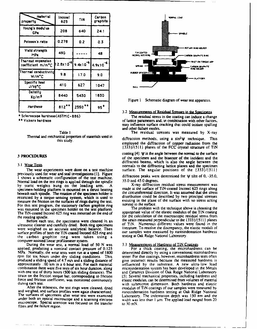
i Inconel Carbon N LOAD
rpt625 TiN graphite
YoungP modulus 208 640 24.1
GP* SPINDLE
Poisson's ratio 0.278 0.2 0.3
Yield strength 490 48 TI COATM.
Mpg oCONEL 25 ING
Thermal expansion -FRICTION TOROLu AWcoefficient m/meC I28x10"6 9.4x410 9x10 - ,, CA- B_.c tor
W/ i , PLATFORMI
Ther al conductiv ty 9 .8 17 .0 9 .0 R BBER SPA ER
Specific heat 410 627 1047J/kq*C BALL714CAI
DensityKg/rm3 8440 5430 1830ofwrteta u- -, Figure 1 Schematic diagram of wear test apparatus.
Hardness 812"* 2550* 95*
- - 3.2 Meas rements of Residual Stresses in the Specimens* Scleroscope hardness(ASTM C- 886) The residual stress in the coating can induce a change
Yickers hardness of lattice parameters and, in combination with other factors,may influence surface cracking that could initiate spallingand other failure modes.
Table 1 The residual stresses was measured by X-rayThermal and mechanical properties of materials used in diffraction methods, using a sin2I technique. This
this study. employed the diffraction of copper radiation from the1333)/(511) planes of the FCC crystal structure of TiN
3 PROCEDURES coating [4]. W is the angle between the normal to the surfaceof the specimen and the bisector of the incident and thediffracted beams, which is also the angle between the
3.1 WearTsts normals to the diffracting lattice planes and the specimenThe wear experiments were done on a test machine surface. The angular positions of the (333)/(511 )
previously used for wear and seal investigations ( I ]. Figure diffraction peaks were determined for AV tilts of 0. -35.0,I shows a schematic configuration of the test machine.Normal load on the test rings is applied through the spindle 35.0 and 45.0 degrees.by static weights hung on the loading arm. A X-ray diffraction residual stress measurement wasspecimen-holding platform is mounted on a thrust bearing made at the surface of TiN-coated Inconel 625 rings alongbeneath each spindle. The rotation of the specimen holder is the circumferential direction. It was assumed that the stressrestricted by a torque-sensing system, which is used to distribution could be described by two principal stressesmeasure the friction on the surfaces of rings during the test. existing in the plane of the surface with no stress actingFor this test program, the stationary carbon graphite ring normal to the surface.was mounted in the specimen holder on the test platform. The problem with the technique above is choosing theThe TiN-coated Inconel 625 ring was mounted on the end of appropriate value of the elastic modulus of the TiN coatingthe rotating spindle, for the calculation of the macroscopic residual stress from
Before each test, the specimens were cleaned in an the strain measured perpendicular to the (333)/(511) planesultrasonic cleaner and carefully dried. Both ring specimens of TiN. Numerous different values were found in thewere weighed on an accurate analytical balance. Then literature. To resolve the discrepancy, the elastic moduli ofsurface profiles of both the TiN-coated Inconel 625 ring and our samples were measured by nanoindentation hardnessthe carbon graphite ring were taken using a testing at Oak Ridge National Laboratory.computer-assisted linear profilometer system.
During the wear test, a normal load of 50 N was 3.3 Measurements of Hardness of TiN Coatingsapplied, producing a nominal contact pressure of 0.125 For a thick coating, the microhardness can beMPa. Normally, the wear tests were run at a speed of 1800 determined directly by using a conventional microhardnessrpm for six hours under dry sliding conditions. This tester. For thin coatings, however, microhardness tests oftenproduced a sliding speed of 4.7 mis and a sliding distance of give incorrect results because the measured hardness isapproximately .00 km in a 6 hour test. For each material influenced by the substrate. A new ultra-low loadcombination there were five tests of six hour duration, along microindentation system has been developed in the Metalswith one test of thirty hours (500 km sliding distance). The and Ceramics Division of Oak Ridge National Laboratorystrain on the friction torque bar, corresponding to friction [51. Several mechanical properties, including hardness andforce and friction coefficient, was monitored continuously elastic modulus, can be determined from volumes of materialduring each test. with submicron dimension. Both hardness and elastic
After the tribotests, the test rings were cleaned, dried modulus of TiN coatings of our samples were measured byand weighed, and surface profiles were again characterized. nanoindentation hardness testing at Oak Ridge NationalThe surfaces of specimens after wear test were examined Laboratory. The indentation depth was 150 nm and theunder both an optical microscope and a scanning electron width was less than I jim. The applied load ranged from 20microscope. Special attention was focused on the transfer to 30 inN.films and the failure region.
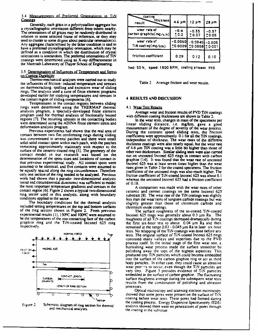
3.4 Measurements of Preferred Orientations in TiN coating -
Coatngs thuct nes 4.6 om 12 0m 28imGenerally, each grain in a polycrystalline aggregate has result
a crystallographic orientation different from others nearby. wear rate of -0.4 -0.33 -0.37The orientations of all grains nay be randomly distributed in carbon graphite( mg,/n) 0.2 + 0.07 0.05relation to some selected frame of reference, or they may - -tend to cluster to some degree about particular orientation(s). wear rate of -0.0060 -0 0045 -0 .005Any aggregate characterized by the latter condition is said to TiN coati ng(mg/kin) 110.0009 t0.0008 1 0.001have a preferred crystallographic orientation, which may bedefined as a condition in which the distribution of crystalorientations is nonrandom. The preferred orientations of TiN friction coefficient 0.09 0.12 0.10coatings were determined using an X-ray diffractometer in -
the Materials Laboratory of Thayer School of Engineering. load: 50 N, speed: 1800 RPM, coating process PYD
3.5 Determination of Influences of Temperature and Stresson Coating Durability
Thermo-mechanical analyses were carried out to studythe influences of friction- induced temperture and stresses Table 2 Average friction and wear results.on thermocracking, spalling and excessive wear of slidingrings. The analysis used a suite of finite element programsdeveloped earlier for studying temperatures and stresses inthe contact region of sliding components [6]. 4 RESULTS AND DISCUSSION
Temperatures in the contact regions between slidingrings were determined using the THERMAP thermal 4.1 Wear Test Resultsanalysis program, a specially-developed finite element Average wear and friction results of PVD TiN coatingsprogram used for thermal analysis of frictionally heated with different coating thicknesses are shown in Table 2.regions [7]. The resulting stresses in the contacting bodies In the wear tests, changes in mass of the specimens perwere determined using the ADINA finite element stress and linear sliding distance, i.e. mg/km, gave a gooddeformation analysis program. measurement of the degree of severity of the wear process.
Previous experiments had shown that the real area of During the constant speed sliding tests, the frictioncontact between two flat conforming rings during sliding coefficients were approximately 0.1 for all the TN coatings,was concentrated in several patches and there were small independent of thickness. The wear rates of the differentsolid-solid contact spots within each patch, with the patches thickness coatings were also nearly equal, but the wear rateremaining approximately stationary with respect to the of 4.6 pim TiN coating was a little bit higher than those ofsurface of the ceramic-coated ring [I]. The geometry of the other two thicknesses. Similar sliding tests wee also carriedcontact model in our research was based on the out on uncoated Inconel 625 rings in contact with carbondetermination of the spots sizes and locations of contact in graphite [141. It was found that the wear rate of uncoatedthat previous experimental study. All contact spots were Inconel 625 was at least seven times higher than the wearassumed to be identical, and five contacts were assumed to rates given in Table 2 for the coated specimens. The frictionbe equally spaced along the ring circumference. Therefore coefficient of the uncoated rings was also much higher. Theonly one section of the ring needed to be analyzed. Previous friction coefficient of TiN-coated Inconel 625 was about 0.1work had shown that a pseudo- two-dimensional analysis whereas the uncoated Inconel 625 had a friction coefficient(axial and circumferential directions) was sufficient to model of 0.18.the most important temperature gradients and stresses in the A comparison was made with the wear rates of othercontact region [6]. Figure 2 shows a typical two-dimensional ceramic and cermet coatings on the same Inconel 625ring sector used in this analysis, along with boundary substrate [8]. The wear rate of the TiN coatings was slightlyconditions applied to the sector. less than the wear rates of tungsten carbide coatings but was
The boundary conditions for the thermal analysis slightly greater than those of chromium carbide andincluded setting temperatures on the top and bottom surfaces chromium oxide coatings.of the ring section shown in Figure 2. From previous The surface roughness of the as-coated TiN-coatedexperimental results [ I, 15oC and 100OC were assumed to Inconel 625 rings was generally about 0.3 gm Ra. Thebe the temperatures of the non-contacting face of the carbon roughness of all TiN coatings decreased dramatically duringgraphite ring and the TiN-coated Inconel 625 ring the first six-hour test to about 0.04 gm Ra and thenrespectively, remained in the range 0.03 - 0.045 pm Ra in later six-hour
tests. No relapping of the TiN coatings was done before anyNORMAL FORCE TTOP tests. The original surface of TiN-coated Inconel 625 rings
I, , + , + consisted many valleys and asperities due to the PVDprocess itself. In the initial stage of the first wear test. a
Q C T ON 4- INCONL62S burnishing wear process made the surface smoother byF3CT3 Npolishing away the tops of the highest asperities. This
4-CE produced tiny TiN particles which could become embeddedinto the surface of the carbon graphite ring or act as third
TiN body particles. In either case, they could cause an abrasive4wear proc--s to occur, even though the TiN particles are
0 very tiny. Figure 3 provides evidence of TiN particlesCARBON CONTACT LENGTH embedded in the surface of carbon graphite. The fluctuating
surface roughness average during the subsequent wear testsGRAPHITE results from the combination of polishing and abrasionLENGTH OF RING SECTION processes.
Optical microscopy and scanning electron microscopyshowed that some pores were present on the surface of TiNcoating before wear tests. These pores had formed duringthe coating process. Energy Dispersive Spectrometry (EDS)
Figure 2 Schematic diagram of ring section for thermal analysis showed there were no penetrations of pores throughand mechanical analyses. the coating to the substrate.
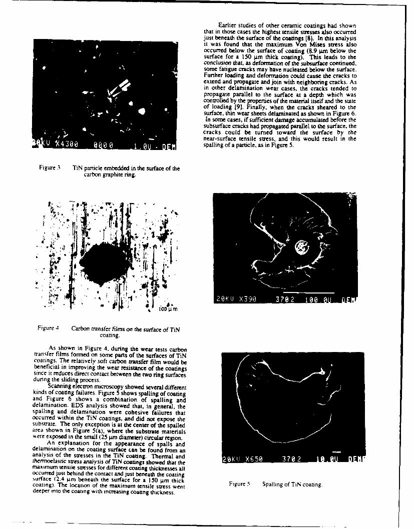
Earlier studies of other ceramic coatings had shownthat in those cases the highest tensile stresses also occurredjust beneath the surface of the coatings [8]. In this analysisit was found that the maximum Von Mises stress alsooccurred below the surface of coating (8.9 iim below thesurface for a 150 gtm thick coating). This leads to theconclusion that, as deformation of the subsurface continued,some fatigue cracks may have nucleated below the surface.Further loading and deformation could cause the cracks toextend and propagate and join with neighboring cracks. Asin other delamination wear cases, the cracks tended topropagate parallel to the surface at a depth which wascontrolled by the properties of the material itself and the stateof loading [9]. Finally, when the cracks sheared to thesurface, thin wear sheets delaminated as shown in Figure 6.In some cases, if sufficient damage accumulated before the
subsurface cracks had propagated parallel to the surface, thecracks could be turned toward the surface by thenear-surface tensile stress, and this would result in the
4 X spalling of a particle, as in Figure 5.
Figure 3 TiN particle embedded in the surface of thecarbon graphite ring.
TW.
* . .
20K,1 X390 PO 2 10
Figure 4 Carbon transfer films on the surface of TiNcoating.
As shown in Figure 4. during the wear tests carbontransfer films formed on some parts of the surfaces of TiNcoatings. The relatively soft carbon transfer film would bebeneficial in improving the wear resistance of the coatingssince it reduces direct contact between the two ring surfacesdunng the sliding process.
Scanning electron microscopy showed several differentkinds of coating failures. Figure 5 shows spalling of coatingand Figure 6 shows a combination of spalling anddelamination. EDS analysis showed that, in general, thespalling and delamination were cohesive failures thatoccurred within the TiN coatings, and did not expose thesubstrate. The only exception is at the center of the spalledarea shown in Figure 5(a), where the substrate materials,Aere exposed in the small (25 )arm diameter) circular region.
An explanation for the appearance of spalls anddelamination on the coating surface can be found from ananalysis of the stresses in the TiN coating. Thermal andthermoelastic stress analysis of TiN coatings showed that the ""X537 21lOEmaximum tensile stresses for different coating thicknesses alloccurred just behind the contact and just beneath the coatingsurface (2.4 4±m beneath the surface for a 150 gm thickcoating). The location of the maximum tensile stress went Figure 5 Spalling of TiN coating.deeper into the coating with increasing coating thickness.
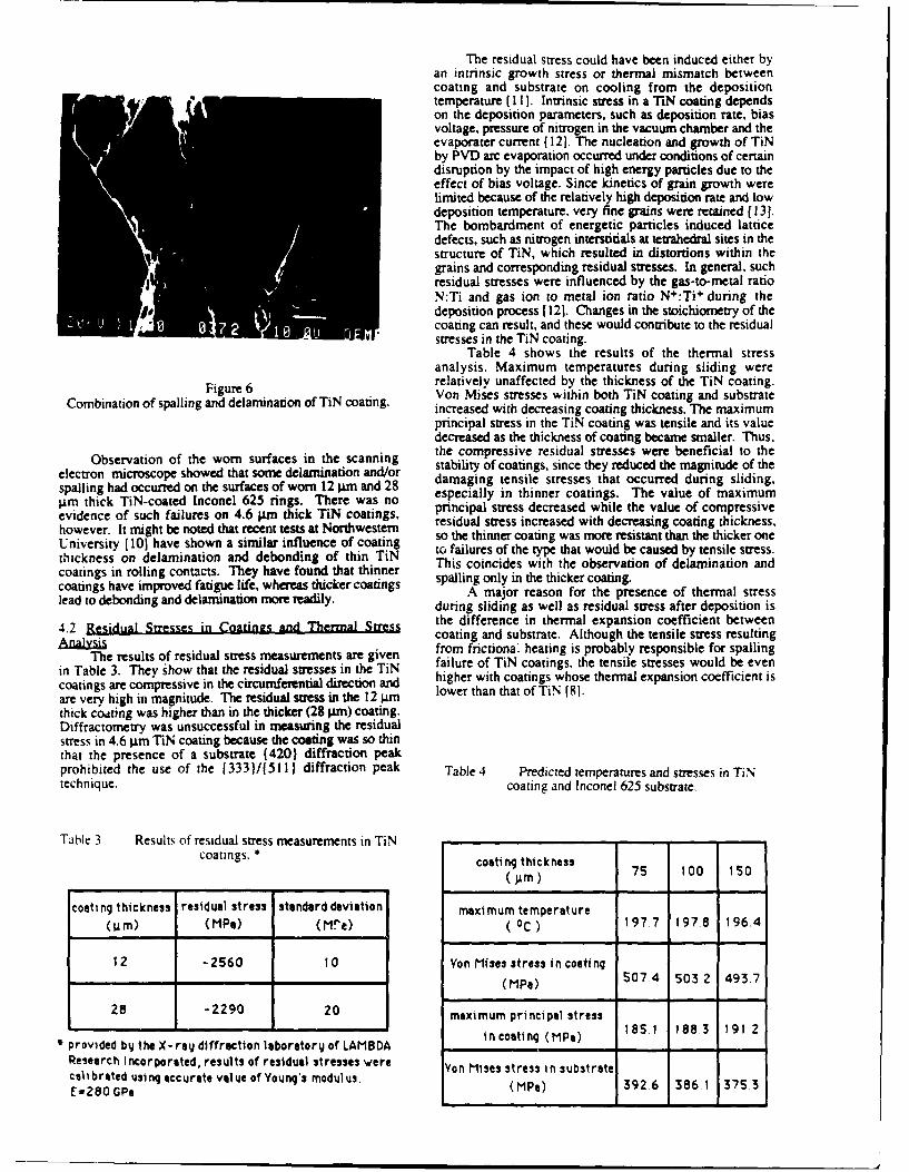
The residual stress could have been induced either byan intrinsic growth stress or thermal mismatch betweencoating and substrate on cooling from the depositiontemperature C I l1. Intrinsic stress in a TiN coating dependson the deposition parameters, such as deposition rate, biasvoltage, pressure of nitrogen in the vacuum chamber and theevaporater current ( 121. The nucleation and growth of TiNby PVD arc evaporation occurred under conditions of certaindisruption by the impact of high energy particles due to theeffect of bias voltage. Since kinetics of grain growth werelimited because of the relatively high deposition rate and lowdeposition temperature, very fine grains were retained [ 13 1.The bombardment of energetic particles induced latticedefects, such as nitrogen interstitials at tetrahedral sites in thestructure of TiN, which resulted in distortions within thegrains and corresponding residual stresses. In general, suchresidual stresses were influenced by the gas-to-metal ratioN:Ti and gas ion to metal ion ratio N :Ti during thedeposition process 1121. Changes in the stoichiometry of thecoating can result, and these would contribute to the residualstresses in the TiN coating.
Table 4 shows the results of the thermal stressanalysis. Maximum temperatures during sliding wererelatively unaffected by the thickness of the TiN coating.
Figure 6 Von Mises stresses within both TiN coating and substrateCombination of spalling and delamination of TiN coating, increased with decreasing coating thickness. The maximum
principal stress in the TiN coating was tensile and its valuedecreased as the thickness of coating became smaller. Thus,
Observation of the worn surfaces in the scanning the compressive residual stresses were beneficial to the
electron microscope showed that some delamination and/or stability of coatings, since they reduced the magnitude of the
spalling had occurred on the surfaces of worn 12 im and 28 damaging tensile stresses that occurred during sliding,
im thick TiN-coated Inconel 625 rings. There was no especially in thinner coatings. The value of maximum
evidence of such failures on 4.6 ;Lm thick TiN coatings, principal stress decreased while the value of compressivehowever. It might be roted that recent tests at Northwestern residual stress increased with decreasing coating thickness,University [10 have shown a similar influence of coating so the thinner coating was more resistant than the thicker onethickness on delamination and debonding of thin TiN to failures of the type that would be caused by tensile stress.
coatings in rolling contacts. They have found that thinner This coincides with the observation of delamination and
coatings have improved fatigue life, whereas thicker coatings spalling only in the thicker coating.A major reason for the presence of thermal stress
lead to debonding and delamination more readily. during sliding as well as residual stress after deposition is
4.2 Residual Stresses in Coatings and Thermal Stress the difference in thermal expansion coefficient between
Anlysi coating and substrate. Although the tensile stress resulting
The results of residual stress measurements are given from frictional heating is probably responsible for spallingin Table 3. They show that the residual stresses in the TiN failure of TiN coatings, the tensile stresses would be even
coatings are compressive in the circumferential direction and higher with coatings whose thermal expansion coefficient is
are very high in magnitude. The residual stress in the 12 ;,m lower than that of TiN [8].thick coating was higher than in the thicker (28 gzm) coating.Diffractometry was unsuccessful in measuring the residualstress in 4.6 gIm TiN coating because the coating was so thinthat the presence of a substrate (420) diffraction peakprohibited the use of the [333)/(511 ) diffraction peak Table 4 Predicted temperatures and stresses in TiNtechnique. coating and inconel 625 substrate.
Table 3 Results of residual stress measurements in TiNcoatings. coating thickness 75 100 150
coating thickness residual stress standard deviation maximum temperature
(4im) (MPa) (Me) (oC) 197,7 197.8 196.4
12 -2560 0 Yon rises stress in coating(PPa) 507.4 5032 493.7
28 -2290 20 maximum principal stress
icoating (P1883 1912provided by the X-ray diffraction laboratory of LAMBDAResearch Incorporated, results of residual stresses were Yon Mises stress in substratecalibrated using accurate value of Young's modulus,.E=280 GPa (MPa) 3926 386.1 375.3
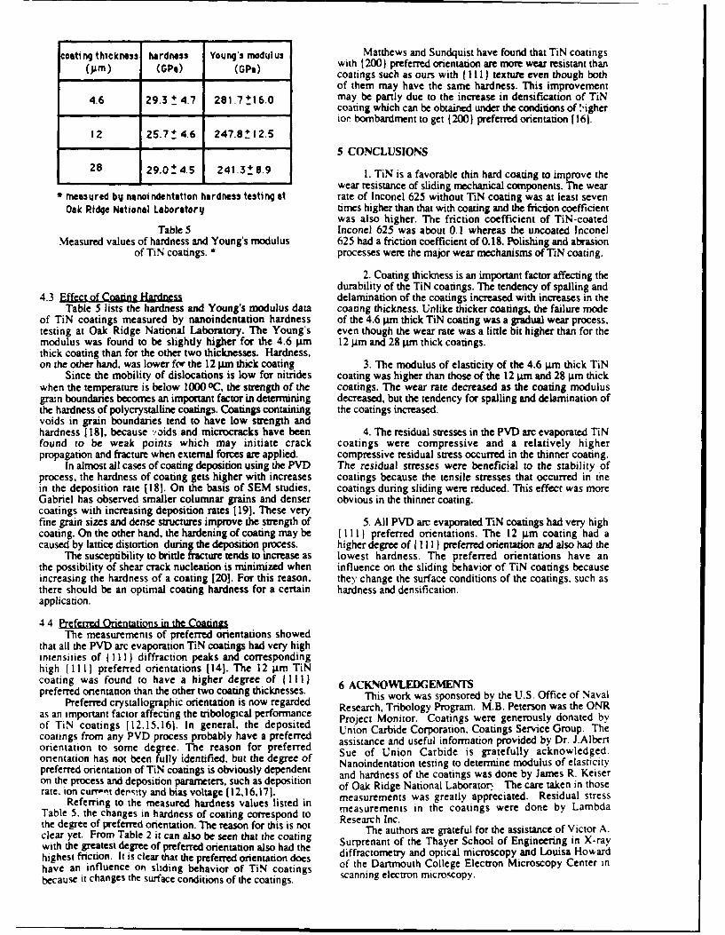
costing thickness hardness Young's modulus Matthews and Sundquist have found that TiN coatings(AM) (GPe) (GPe) with 1200) preferred orientation are more wear resistant than
coatings such as ours with I 111) texture even though bothof them may have the same hardness. This improvement
4.6 29.3 1 4.7 281.7 _1 6.0 may be partly due to the increase in densification of TiNcoating which can be obtained under the conditions of N'igherior bombardment to get (200) preferred orientation [ 161.
12 25.7 ! 4.6 247.8 12.5
5 CONCLUSIONS
28 29.0 _ 4.5 241 .3! 8.9 1. TiN is a favorable thin hard coating to improve the
wear resistance of sliding mechanical components. The wear* measured by nanoindentation hardness testing at rate of Inconel 625 without TiN coating was at least seven
Oak Ridge National Laboratory times higher than that with coating and the friction coefficientwas also higher. The friction coefficient of TiN-coated
Table 5 Inconel 625 was about 0.1 whereas the uncoated InconelMeasured values of hardness and Young's modulus 625 had a friction coefficient of 0.18. Polishing and abrasion
of TiN coatings. * processes were the major wear mechanisms of TiN coating.
2. Coating thickness is an important factor affecting thedurability of the TiN coatings. The tendency of spalling and
4.3 Effect of Coating Hardness delamination of the coatings increased with increases in theTable 5 lists the hardness and Young's modulus data coating thickness. Unlike thicker coatings, the failure mode
of TiN coatings measured by nanoindentation hardness of the 4.6 pn thick TiN coating was a gradual wear process.testing at Oak Ridge National Laboratory. The Young's even though the wear rate was a little bit higher than for themodulus was found to be slightly higher for the 4.6 .im 12 gin and 28 lim thick coatings.thick coating than for the other two thicknesses. Hardness,on the other hand, was lower for the 12 pm thick coating 3. The modulus of elasticity of the 4.6 gJm thick TiN
Since the mobility of dislocations is low for nitrides coating was higher than those of the 12 Ipm and 28 pLm thickwhen the temperature is below 1000oC, the strength of the coatings. The wear rate decreased as the coating modulusgrain boundaries becomes an important factor in determining decreased, but the tendency for spalling and delamination ofthe hardness of polycrystalline coatings. Coatings containing the coatings increased.voids in grain boundaries tend to have low strength andhardness [18], because vaids and microcracks have been 4. The residual stresses in the PVD arc evaporated TiNfound to be weak points which may initiate crack coatings were compressive and a relatively higherpropagation and fracture when external forces are applied, compressive residual stress occurred in the thinner coating.
In almost all cases of coating deposition using the PVD The residual stresses were beneficial to the stability ofprocess, the hardness of coating gets higher with increases coatings because the tensile stresses that occurred in thein the deposition rate ( 18]. On the basis of SEM studies, coatings during sliding were reduced. This effect was moreGabriel has observed smaller columnar grains and denser obvious in the thinner coating.coatings with increasing deposition rates [19]. These veryfine grain sizes and dense structures improve the strength of 5. All PVD arc evaporated TiN coatings had very highcoating. On the other hand, the hardening of coating may be ll) preferred orientations. The 12 gam coating had acaused by lattice distortion during the deposition process. higher degree of { }I preferred orientation and also had the
The susceptibility to brittle fracture tends to increase as lowest hardness. The preferred orientations have anthe possibility of shear crack nucleation is minimized when influence on the sliding behavior of TiN coatings becauseincreasing the hardness of a coating [20]. For this reason, they change the surface conditions of the coatings, such asthere should be an optimal coating hardness for a certain hardness and densification.application.
4.4 Preferred Orientations in the CoatingsThe measurements of preferred orientations showed
that all the PVD arc evaporation TiN coatings had very highintensities of (Ill ) diffraction peaks and correspondinghigh (I I I I preferred orientations [14]. The 12 .m TiNcoating was found to have a higher degree of (1111 6 ACKNOWLEDGEMENTSpreferred orientation than the other two coating thicknesses.Preferred crystallographic orientation is now regarded This work was sponsored by the U.S. Office of Naval
asean rrmportantaoraecienton ow pear ne Research, Tribology Program. M.B. Peterson was the ONRas an important factor affecting the tribologcal performance Project Monitor. Coatings were generously donated byof TiN coatings [ 12,15,161. In general, the deposited Pj Mon tor . Coati ngs erusl donae by
cotnsfrom any PVD process probably have a preferred Union Carbide Corporation, Coatings Service Group. Thecoatingsferred assistance and useful information provided by Dr. J.Albertorientation to some degree. The reason for preferred Sue of Union Carbide is gratefully acknowledged.orientation has not been fully identified, but the degree of Nanoindentation testing to determine modulus of elasticitypreferred orientation of TiN coatings is obviously dependent and hardness of the coatings was done by James R. Keiseron the process and deposition parameters, such as deposition of Oak Ridge National Laboraton The care taken in thoserate, ion curr,'t ders.ty and bias voltage [12,16,171. meaurme as g rat app re Rein tress
Referring to the measured hardness values listed in measurements was greatly appreciated. Residual stressTable 5. the changes in hardness of coating correspond to Research Inc.the degree of preferred orientation. The reason for this is not The authors are grateful for the assistance of Victor Aclear yet. From Table 2 it can also be seen that the coating Surprenant of the Thayer School of Engineering in X-raywith the greatest degree of preferred orientation also had the Surrato the a ye cl of En in Xwrhighest friction. It is clear that the preferred orientation does diffractometry and optical microscopy and Louisa Howardhave an influence on sliding behavior of TiN coatings of the Dartmouth College Electron Microscopy Center nbecause it changes the surface conditions of the coatings. scanning electron microscopy.
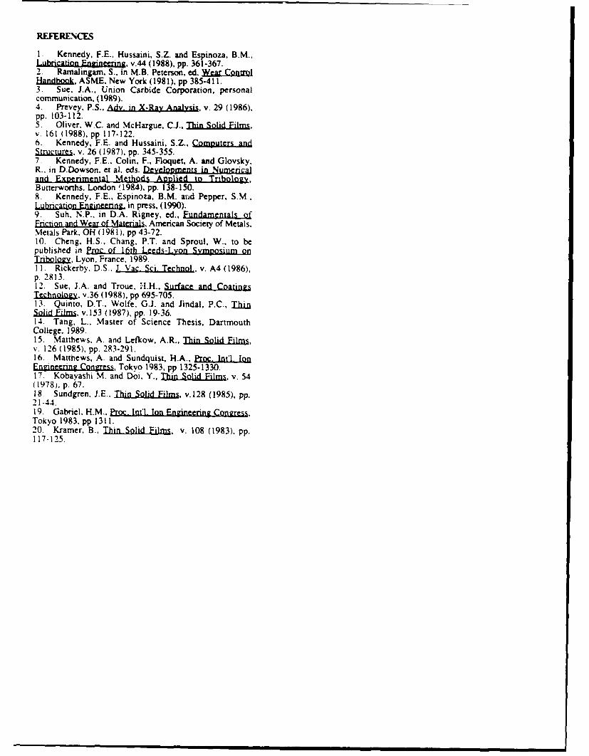
REFERENCES
1. Kennedy. F.E.. Hussaini, S.Z. and Espinoza, B.M.,Lubrication Engineering, v.44 (1988), pp. 361-367.2. Ramalingarn, S.. in M.B. Peterson, ed. WarControiandbok, ASME, New York (1981), pp 385-411.
3. Sue. J.A., Union Carbide Corporation, personalcommunication, (1989).4. Prevey, P.S., Ady. in X-Ray Analysis, v. 29 (1986),pp. 103-112.5. Oliver. W.C. and McHargue, C.J., Thin Solid Films,v. 161 (1988), pp 117-122.6. Kennedy, FE. and Hussaini, S.Z., ComplandStructures, v. 26 (1987), pp. 345-355.7. Kennedy, F.E., Colin, F., Floquet, A. and Glovsky,R., in D.Dowson, et al, eds. Developments in Numericaland Experimental Methods Applied to Tribology,Butterworths. London '1984), pp. 138-150.8. Kennedy, F.E., Espinoza, B.M. atrd Pepper, S.M.,Lubrication Engineering. in press, (1990).9. Suh, N.P., in D.A. Rigney, ed., Fundamentals ofFriction and Wear of Materials, American Society of Metals,Metals Park. OH (1981), pp 43-72.10. Cheng. H.S., Chang, P.T. and Sproul, W., to bepublished in Proc of 16th Leeds-Lyon Symposium onTI.ribIlgy. Lyon. France, 1989.11. Rickerby. D.S.. J. Vac. Sci. Technol., v. A4 (1986),p. 2813.12. Sue, J.A. and Troue, .H., Surface and CoatingsTechnology, v.36 (1988), pp 695-705.13. Quinto, D.T., Wolfe, G.J. and Jindal, P.C., ThbinSolid Films. v. 153 (1987), pp. 19-36.14. Tang, L., Master of Science Thesis, DartmouthCollege, 1989.15. Matthews, A. and Lefkow, A.R., Thin Solid Films,v. 126 (1985), pp. 283-291.16. Matthews, A. and Sundquist, H.A., Proc. Int'l. IonEngineering Congress, Tokyo 1983, pp 1325-1330.17 Kobayashi M. and Doi. Y., Thin Solid Films, v. 54(1978), p. 6 7 .18. Sundgren, J.E.. Thin Solid Films, v.128 (1985), pp.21-44.19. Gabriel, H.M., Proc. Intl. Ion Engneering Congress,Tokyo 1983, pp 1311.20. Kramer, B., Thin Solid Films, v. 108 (1983), pp.117-125.