Embed Size (px)
Citation preview
©2015 Retrospeed 1Tim Miller FEMAG Anwendertreffen 2015 Leutkirch
17 Trends in Dimensioning PM and Reluctance Machines
Trends in Dimensioning PM and Reluctance Machines
Tim Miller
FEMAG Anwendertreffen 201528. 29.Oktober2015
©2015 Retrospeed 2Tim Miller FEMAG Anwendertreffen 2015 Leutkirch
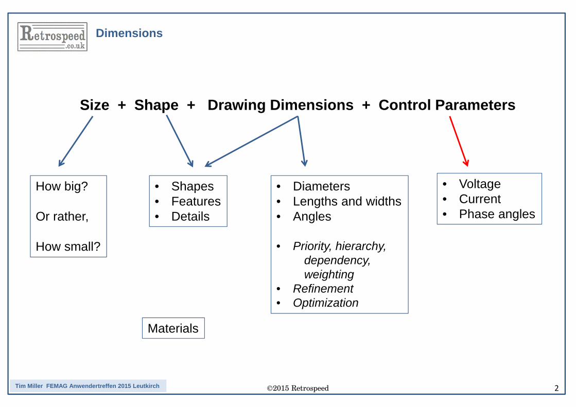
Dimensions
Size + Shape + Drawing Dimensions + Control Parameters
How big?
Or rather,
How small?
• Shapes• Features• Details
• Diameters• Lengths and widths• Angles
• Priority, hierarchy,dependency,weighting
• Refinement• Optimization
Materials
• Voltage• Current• Phase angles
©2015 Retrospeed 3Tim Miller FEMAG Anwendertreffen 2015 Leutkirch
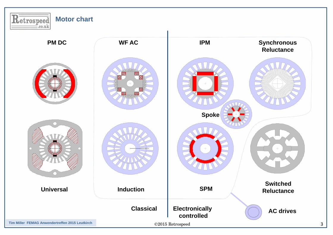
Motor chart
PM DC WF AC IPM Synchronous Reluctance
Spoke
Universal Induction SPMSwitched
Reluctance
AC drivesClassical Electronicallycontrolled
©2015 Retrospeed 4Tim Miller FEMAG Anwendertreffen 2015 Leutkirch
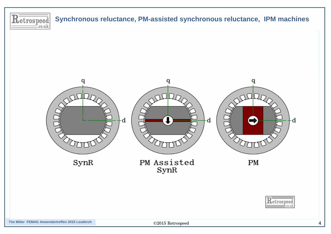
Synchronous reluctance, PM-assisted synchronous reluctance, IPM machines
©2015 Retrospeed 5Tim Miller FEMAG Anwendertreffen 2015 Leutkirch
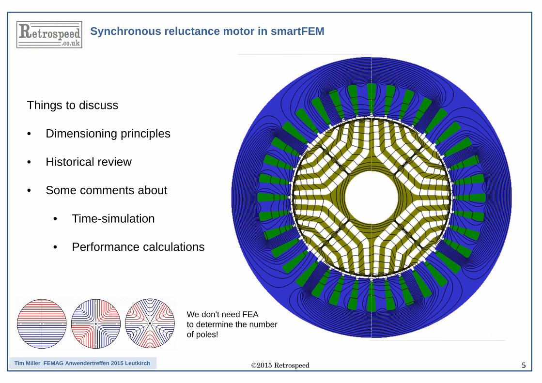
Synchronous reluctance motor in smartFEM
Things to discuss
• Dimensioning principles
• Historical review
• Some comments about
• Time-simulation
• Performance calculations
We don't need FEA to determine the numberof poles!
©2015 Retrospeed 6Tim Miller FEMAG Anwendertreffen 2015 Leutkirch
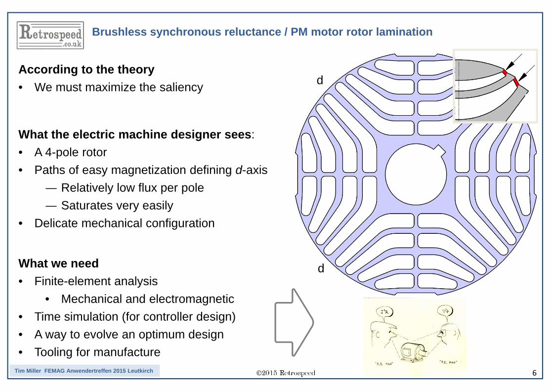
Brushless synchronous reluctance / PM motor rotor lamination
What the electric machine designer sees:• A 4-pole rotor• Paths of easy magnetization defining d-axis— Relatively low flux per pole— Saturates very easily• Delicate mechanical configuration
According to the theory• We must maximize the saliency
What we need• Finite-element analysis
• Mechanical and electromagnetic• Time simulation (for controller design)• A way to evolve an optimum design• Tooling for manufacture
d
d
©2015 Retrospeed 7Tim Miller FEMAG Anwendertreffen 2015 Leutkirch
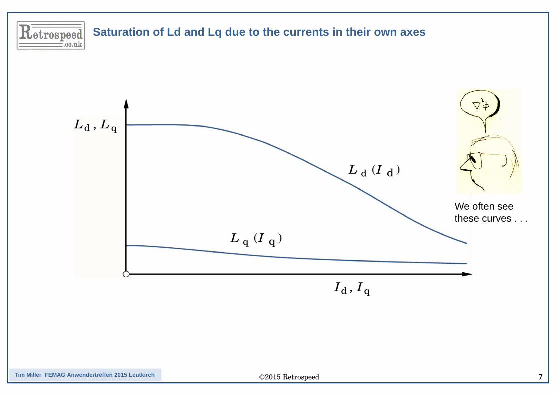
Saturation of Ld and Lq due to the currents in their own axes
We often see these curves . . .
©2015 Retrospeed 8Tim Miller FEMAG Anwendertreffen 2015 Leutkirch
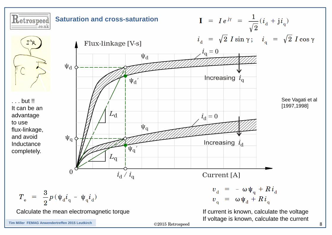
Saturation and cross-saturation
If current is known, calculate the voltageIf voltage is known, calculate the current
Calculate the mean electromagnetic torque
See Vagati et al[1997,1998]
. . . but !!It can be an advantage to useflux-linkage, and avoid Inductancecompletely.
©2015 Retrospeed 9Tim Miller FEMAG Anwendertreffen 2015 Leutkirch
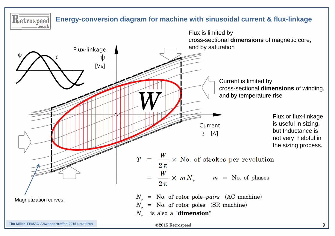
Energy-conversion diagram for machine with sinusoidal current & flux-linkage
Flux is limited by cross-sectional dimensions of magnetic core,and by saturation
Current is limited by cross-sectional dimensions of winding, and by temperature rise
Magnetization curves
Flux or flux-linkage is useful in sizing, but Inductance isnot very helpful in the sizing process.
©2015 Retrospeed 10Tim Miller FEMAG Anwendertreffen 2015 Leutkirch
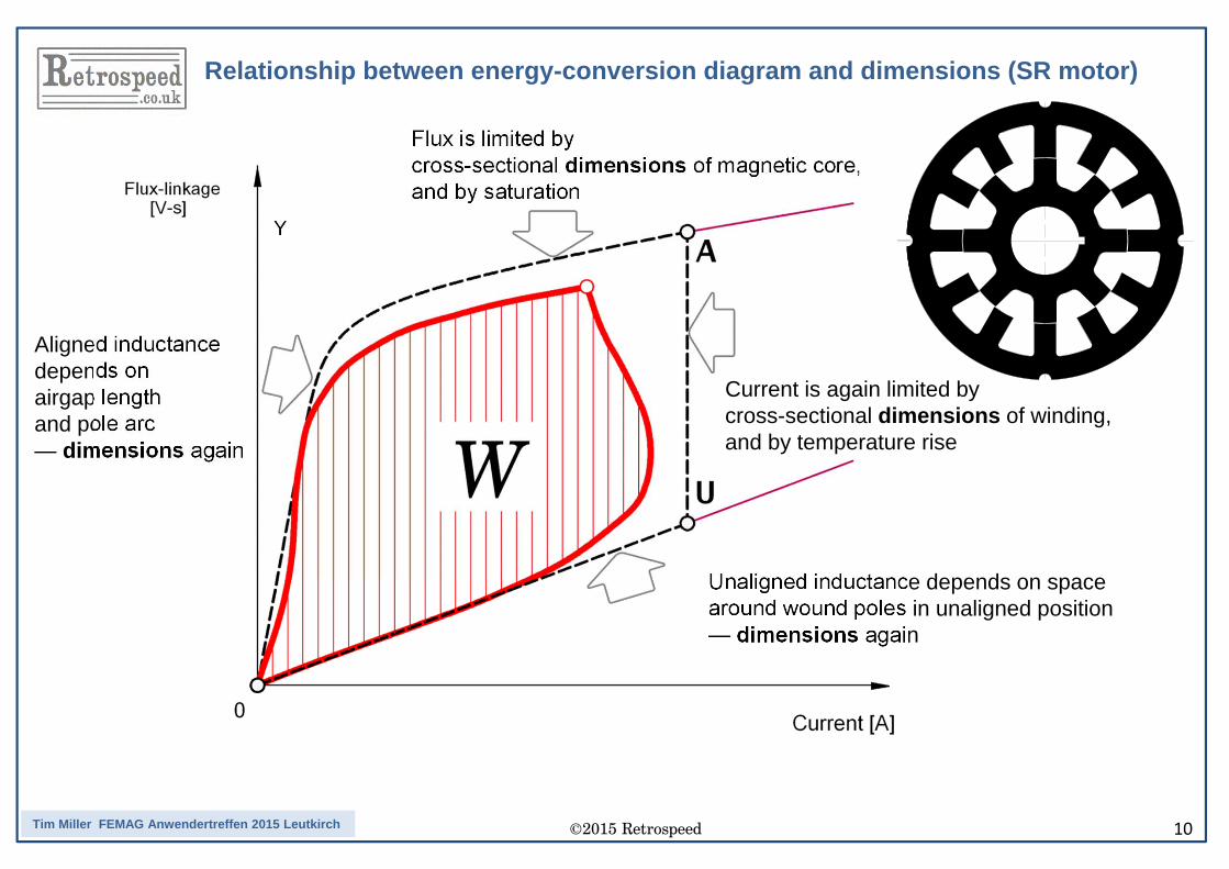
Relationship between energy-conversion diagram and dimensions (SR motor)
Y
Aligned inductance depends onairgap length and pole arc— dimensions again
Unaligned inductance depends on space around wound poles in unaligned position— dimensions again
Flux is limited by cross-sectional dimensions of magnetic core,and by saturation
Current is again limited by cross-sectional dimensions of winding, and by temperature rise
©2015 Retrospeed 11Tim Miller FEMAG Anwendertreffen 2015 Leutkirch
• It can be used for preliminary design or sizing• It is directly related to the machine dimensions and material properties
• It requires only a magnetostatic calculation• No time-stepping simulation required• Current waveform is assumed known
• Suitable for 2-D FEA, but end-effects must be added
• It defines the maximum torque per ampere
• The required voltage can be deduced from it
• It shows several figures of merit
• It can easily be scaled according to the number of turns
• Pre-calculated sets of magnetization curves can be used for dynamic simulation (see next slide)
Features of the simple energy-conversion diagram
©2015 Retrospeed 12Tim Miller FEMAG Anwendertreffen 2015 Leutkirch
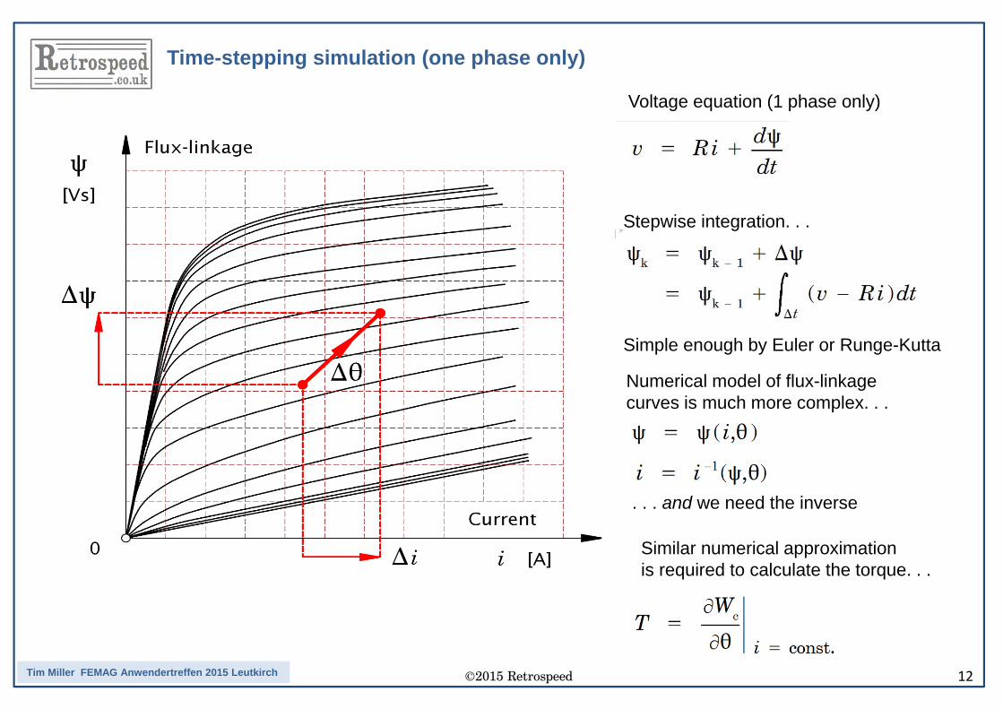
Stepwise integration. . .
Simple enough by Euler or Runge-Kutta
Numerical model of flux-linkagecurves is much more complex. . .
. . . and we need the inverse
Similar numerical approximationis required to calculate the torque. . .
Voltage equation (1 phase only)
Time-stepping simulation (one phase only)
©2015 Retrospeed 13Tim Miller FEMAG Anwendertreffen 2015 Leutkirch
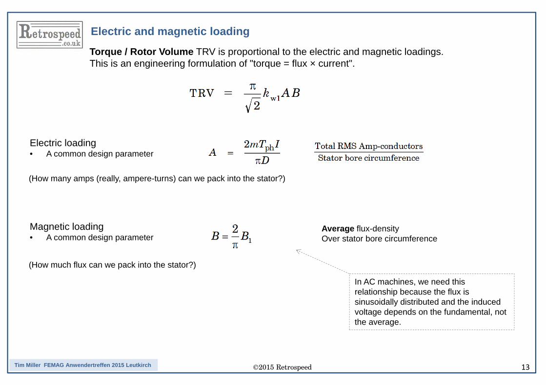
Electric loading• A common design parameter
Magnetic loading• A common design parameter
Average flux-densityOver stator bore circumference
(How many amps (really, ampere-turns) can we pack into the stator?)
(How much flux can we pack into the stator?)
Torque / Rotor Volume TRV is proportional to the electric and magnetic loadings.This is an engineering formulation of "torque = flux × current".
In AC machines, we need this relationship because the flux is sinusoidally distributed and the induced voltage depends on the fundamental, not the average.
Electric and magnetic loading
©2015 Retrospeed 14Tim Miller FEMAG Anwendertreffen 2015 Leutkirch
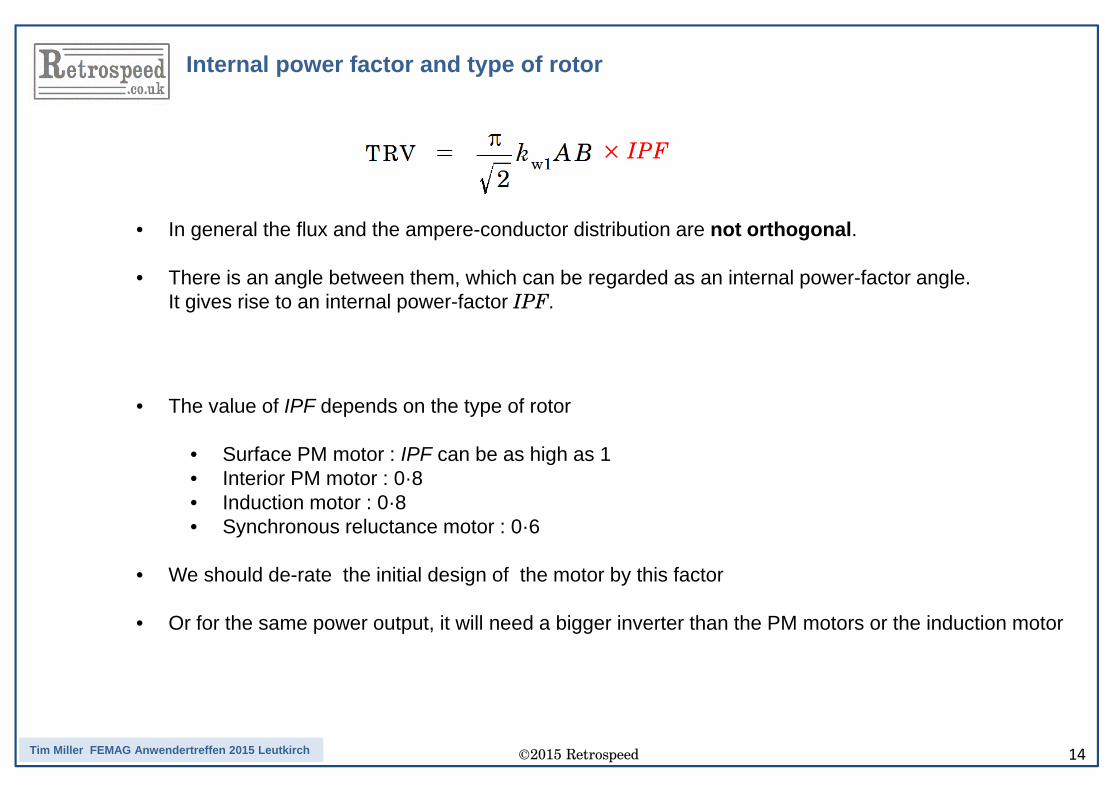
Internal power factor and type of rotor
• In general the flux and the ampere-conductor distribution are not orthogonal.
• There is an angle between them, which can be regarded as an internal power-factor angle. It gives rise to an internal power-factor IPF.
• The value of IPF depends on the type of rotor
• Surface PM motor : IPF can be as high as 1• Interior PM motor : 0·8• Induction motor : 0·8• Synchronous reluctance motor : 0·6
• We should de-rate the initial design of the motor by this factor
• Or for the same power output, it will need a bigger inverter than the PM motors or the induction motor
©2015 Retrospeed 15Tim Miller FEMAG Anwendertreffen 2015 Leutkirch
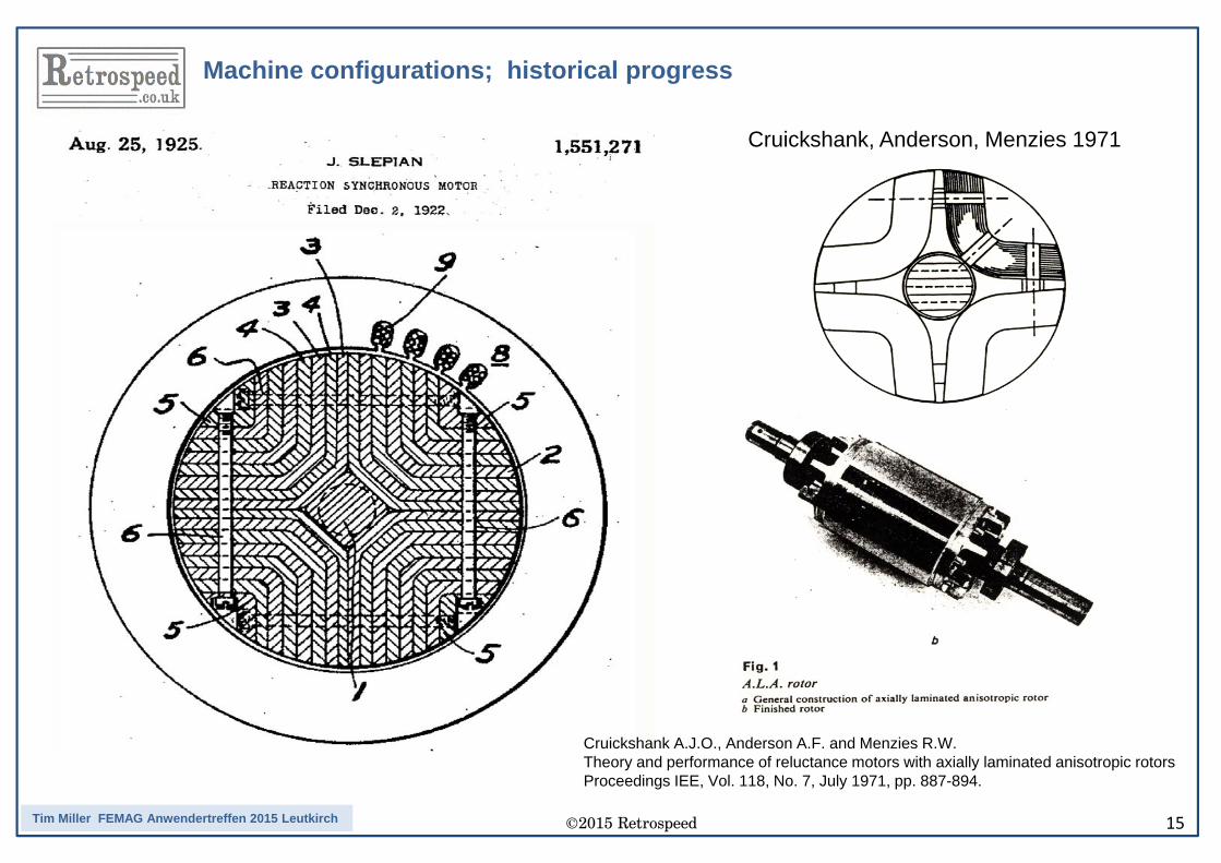
Machine configurations; historical progress
Cruickshank, Anderson, Menzies 1971
Cruickshank A.J.O., Anderson A.F. and Menzies R.W.Theory and performance of reluctance motors with axially laminated anisotropic rotorsProceedings IEE, Vol. 118, No. 7, July 1971, pp. 887-894.
©2015 Retrospeed 16Tim Miller FEMAG Anwendertreffen 2015 Leutkirch
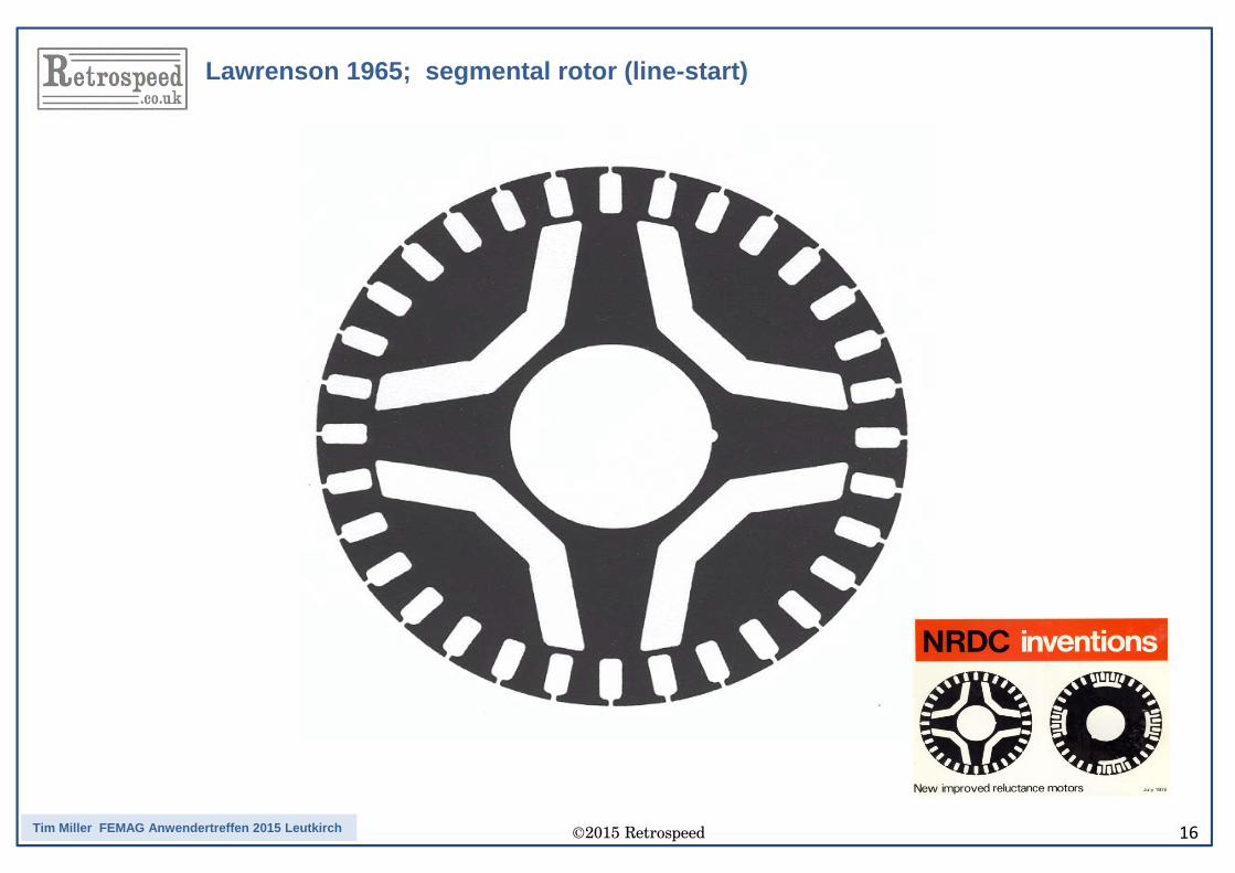
Lawrenson 1965; segmental rotor (line-start)
©2015 Retrospeed 17Tim Miller FEMAG Anwendertreffen 2015 Leutkirch
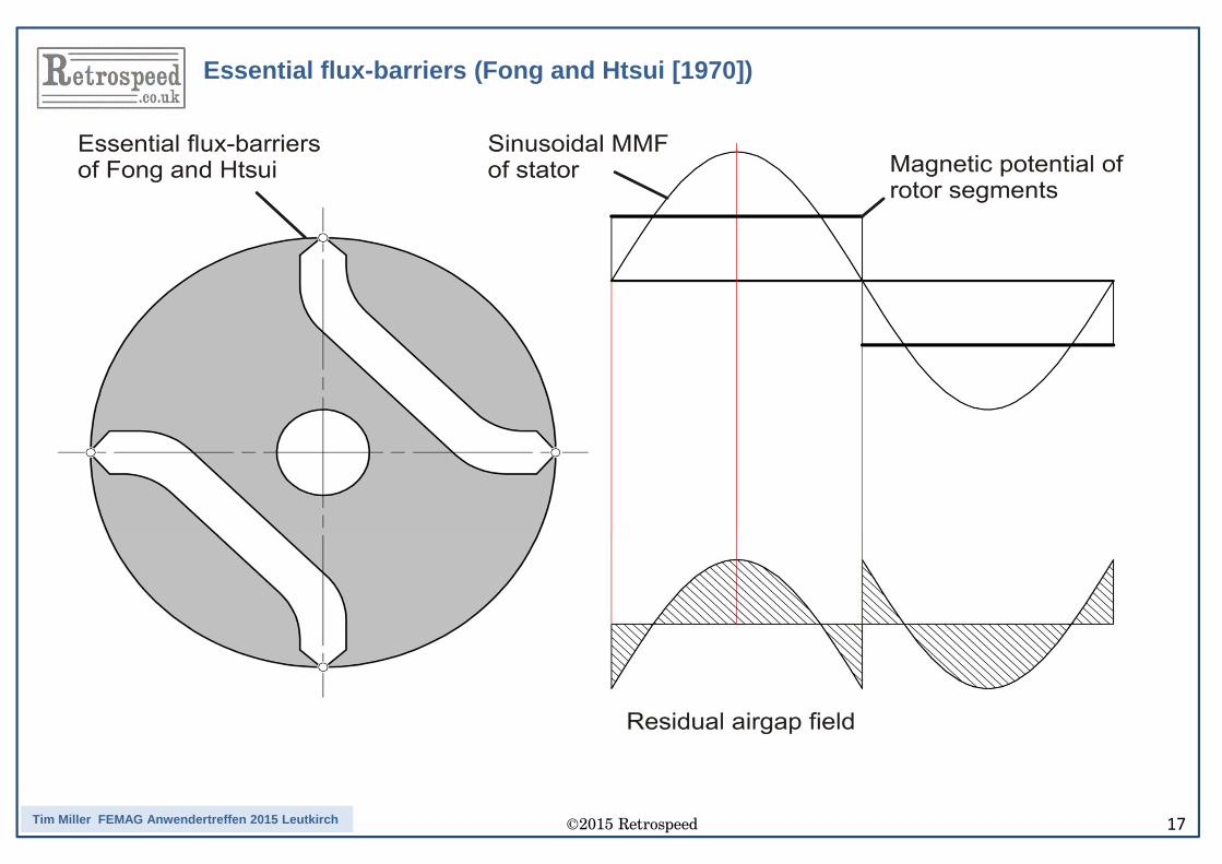
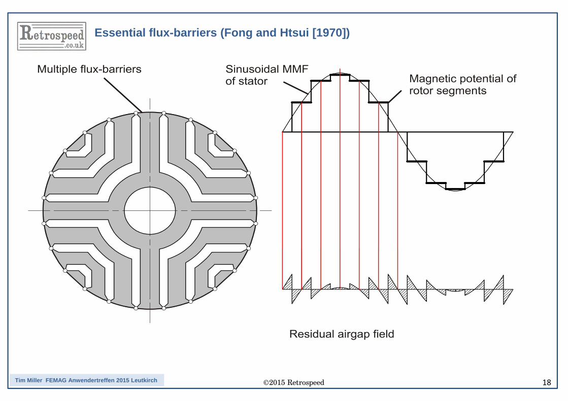
Essential flux-barriers (Fong and Htsui [1970])
©2015 Retrospeed 18Tim Miller FEMAG Anwendertreffen 2015 Leutkirch
Essential flux-barriers (Fong and Htsui [1970])
©2015 Retrospeed 19Tim Miller FEMAG Anwendertreffen 2015 Leutkirch
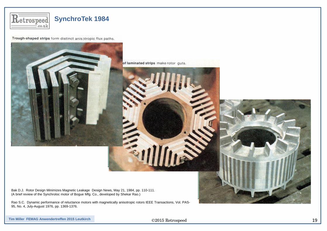
SynchroTek 1984
Bak D.J. Rotor Design Minimizes Magnetic Leakage Design News, May 21, 1984, pp. 110-111.(A brief review of the Synchroloc motor of Bogue Mfg. Co., developed by Shekar Rao.)
Rao S.C. Dynamic performance of reluctance motors with magnetically anisotropic rotors IEEE Transactions, Vol. PAS-95, No. 4, July-August 1976, pp. 1369-1376.
©2015 Retrospeed 20Tim Miller FEMAG Anwendertreffen 2015 Leutkirch
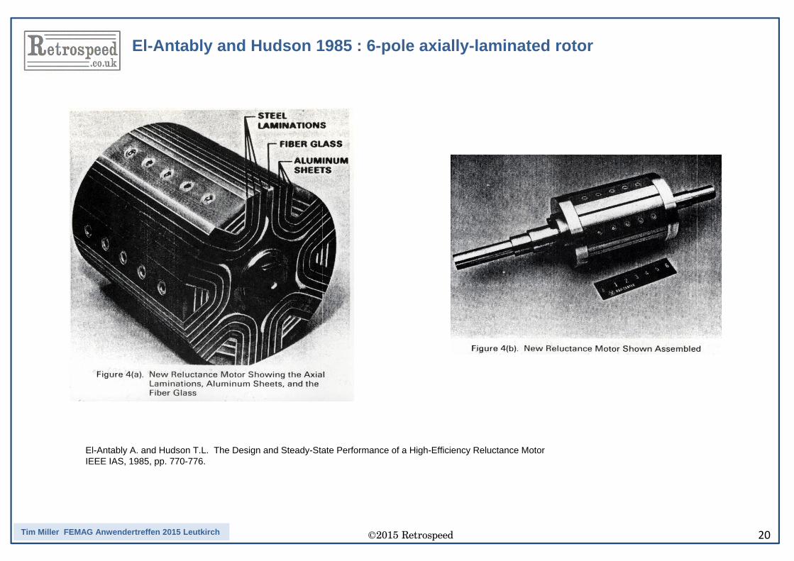
El-Antably and Hudson 1985 : 6-pole axially-laminated rotor
El-Antably A. and Hudson T.L. The Design and Steady-State Performance of a High-Efficiency Reluctance MotorIEEE IAS, 1985, pp. 770-776.
©2015 Retrospeed 21Tim Miller FEMAG Anwendertreffen 2015 Leutkirch
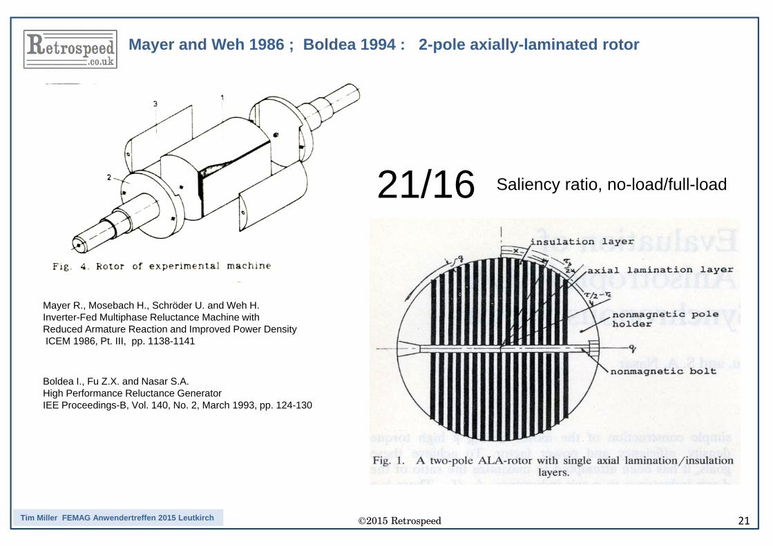
Mayer and Weh 1986 ; Boldea 1994 : 2-pole axially-laminated rotor
21/16 Saliency ratio, no-load/full-load
Mayer R., Mosebach H., Schröder U. and Weh H. Inverter-Fed Multiphase Reluctance Machine with Reduced Armature Reaction and Improved Power DensityICEM 1986, Pt. III, pp. 1138-1141
Boldea I., Fu Z.X. and Nasar S.A. High Performance Reluctance GeneratorIEE Proceedings-B, Vol. 140, No. 2, March 1993, pp. 124-130
©2015 Retrospeed 22Tim Miller FEMAG Anwendertreffen 2015 Leutkirch
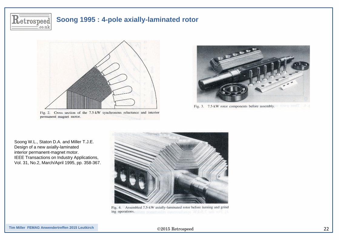
Soong 1995 : 4-pole axially-laminated rotor
Soong W.L., Staton D.A. and Miller T.J.E.Design of a new axially-laminated interior permanent-magnet motor.IEEE Transactions on Industry Applications, Vol. 31, No.2, March/April 1995, pp. 358-367.
©2015 Retrospeed 23Tim Miller FEMAG Anwendertreffen 2015 Leutkirch
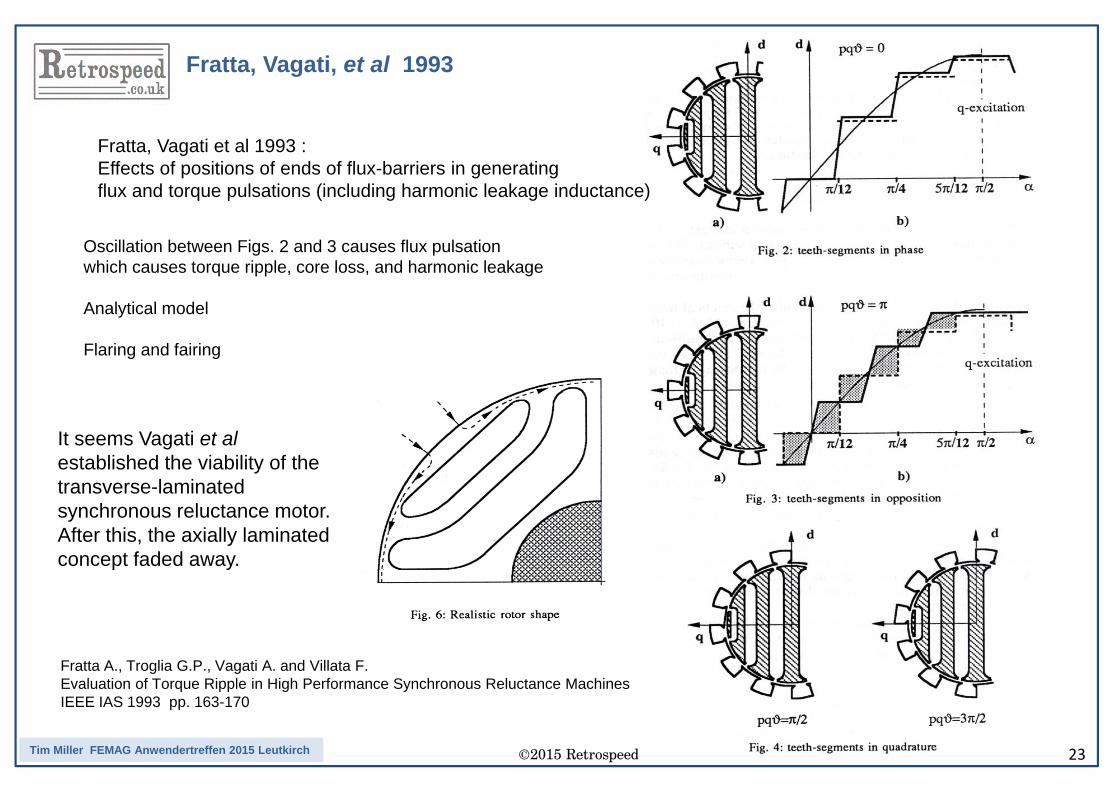
Fratta, Vagati, et al 1993
Oscillation between Figs. 2 and 3 causes flux pulsationwhich causes torque ripple, core loss, and harmonic leakage
Analytical model
Flaring and fairing
Fratta, Vagati et al 1993 : Effects of positions of ends of flux-barriers in generating flux and torque pulsations (including harmonic leakage inductance)
Fratta A., Troglia G.P., Vagati A. and Villata F.Evaluation of Torque Ripple in High Performance Synchronous Reluctance MachinesIEEE IAS 1993 pp. 163-170
It seems Vagati et alestablished the viability of thetransverse-laminated synchronous reluctance motor.After this, the axially laminated concept faded away.
©2015 Retrospeed 24Tim Miller FEMAG Anwendertreffen 2015 Leutkirch
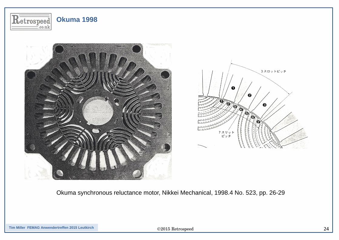
Okuma synchronous reluctance motor, Nikkei Mechanical, 1998.4 No. 523, pp. 26-29
Okuma 1998
©2015 Retrospeed 25Tim Miller FEMAG Anwendertreffen 2015 Leutkirch
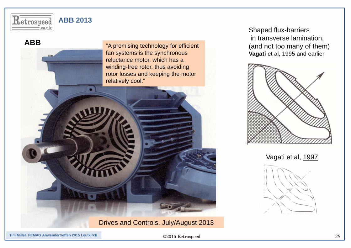
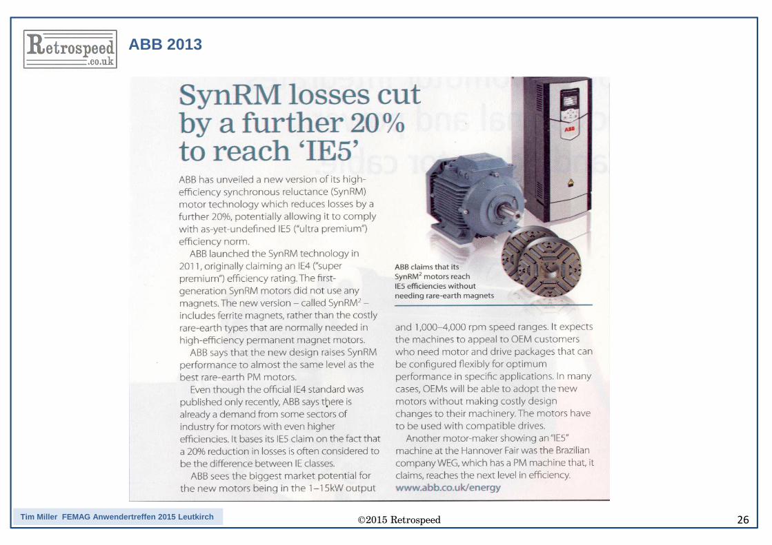
“A promising technology for efficient fan systems is the synchronous reluctance motor, which has a winding-free rotor, thus avoiding rotor losses and keeping the motor relatively cool.”
Drives and Controls, July/August 2013
Shaped flux-barriersin transverse lamination,(and not too many of them)Vagati et al, 1995 and earlier
Vagati et al, 1997
ABB
ABB 2013
©2015 Retrospeed 26Tim Miller FEMAG Anwendertreffen 2015 Leutkirch
ABB 2013
©2015 Retrospeed 27Tim Miller FEMAG Anwendertreffen 2015 Leutkirch
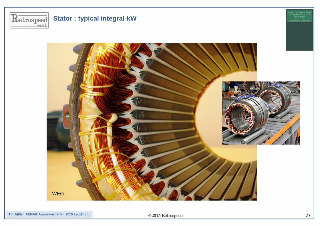
Stator : typical integral-kW
WEG
©2015 Retrospeed 28Tim Miller FEMAG Anwendertreffen 2015 Leutkirch
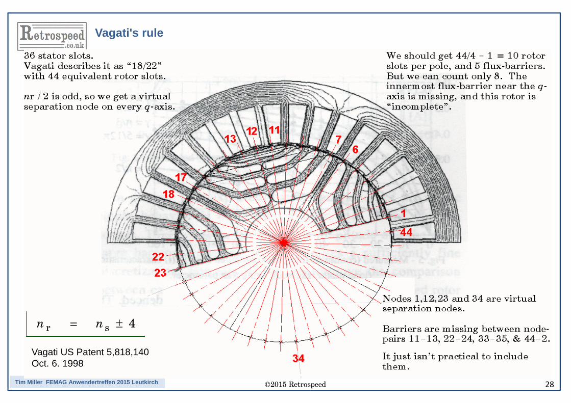
r s 4n n= ±
Vagati US Patent 5,818,140Oct. 6. 1998
Vagati's rule
©2015 Retrospeed 29Tim Miller FEMAG Anwendertreffen 2015 Leutkirch
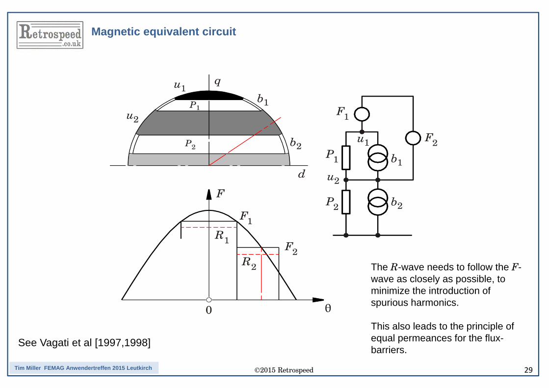
The R-wave needs to follow the F-wave as closely as possible, to minimize the introduction of spurious harmonics.
This also leads to the principle of equal permeances for the flux-barriers.
Magnetic equivalent circuit
See Vagati et al [1997,1998]
©2015 Retrospeed 30Tim Miller FEMAG Anwendertreffen 2015 Leutkirch
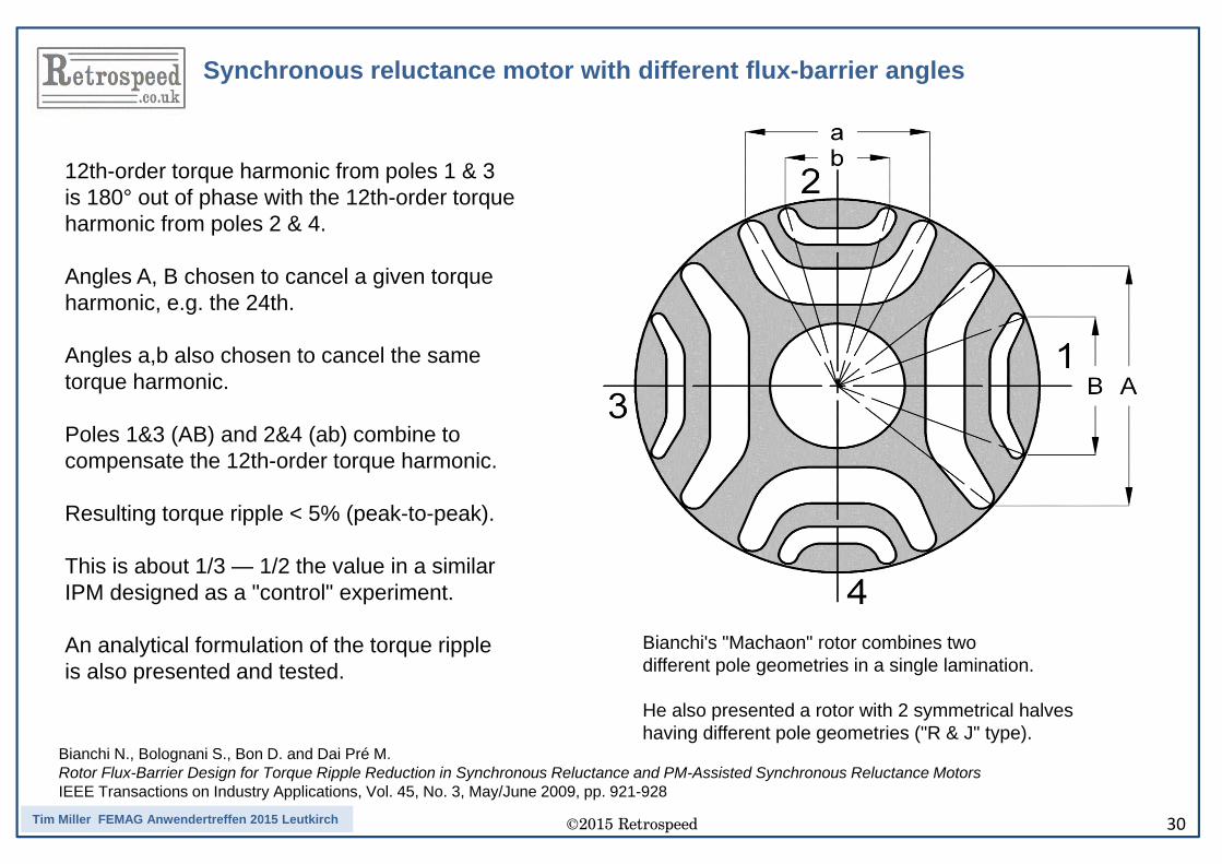
Bianchi N., Bolognani S., Bon D. and Dai Pré M.Rotor Flux-Barrier Design for Torque Ripple Reduction in Synchronous Reluctance and PM-Assisted Synchronous Reluctance MotorsIEEE Transactions on Industry Applications, Vol. 45, No. 3, May/June 2009, pp. 921-928
12th-order torque harmonic from poles 1 & 3 is 180° out of phase with the 12th-order torqueharmonic from poles 2 & 4.
Angles A, B chosen to cancel a given torque harmonic, e.g. the 24th.
Angles a,b also chosen to cancel the same torque harmonic.
Poles 1&3 (AB) and 2&4 (ab) combine to compensate the 12th-order torque harmonic.
Resulting torque ripple < 5% (peak-to-peak).
This is about 1/3 — 1/2 the value in a similar IPM designed as a "control" experiment.
An analytical formulation of the torque rippleis also presented and tested.
Bianchi's "Machaon" rotor combines two different pole geometries in a single lamination.
He also presented a rotor with 2 symmetrical halveshaving different pole geometries ("R & J" type).
Synchronous reluctance motor with different flux-barrier angles
©2015 Retrospeed 31Tim Miller FEMAG Anwendertreffen 2015 Leutkirch
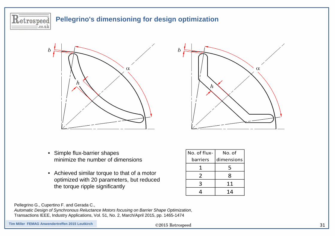
• Simple flux-barrier shapesminimize the number of dimensions
• Achieved similar torque to that of a motor optimized with 20 parameters, but reduced the torque ripple significantly
No. of flux-barriers
No. of dimensions
1 52 83 114 14
Pellegrino G., Cupertino F. and Gerada C., Automatic Design of Synchronous Reluctance Motors focusing on Barrier Shape Optimization, Transactions IEEE, Industry Applications, Vol. 51, No. 2, March/April 2015, pp. 1465-1474
Pellegrino's dimensioning for design optimization
©2015 Retrospeed 32Tim Miller FEMAG Anwendertreffen 2015 Leutkirch
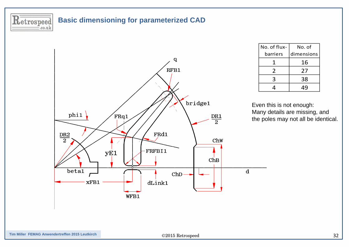
No. of flux-barriers
No. of dimensions
1 162 273 384 49
Even this is not enough:Many details are missing, andthe poles may not all be identical.
Basic dimensioning for parameterized CAD
©2015 Retrospeed 33Tim Miller FEMAG Anwendertreffen 2015 Leutkirch
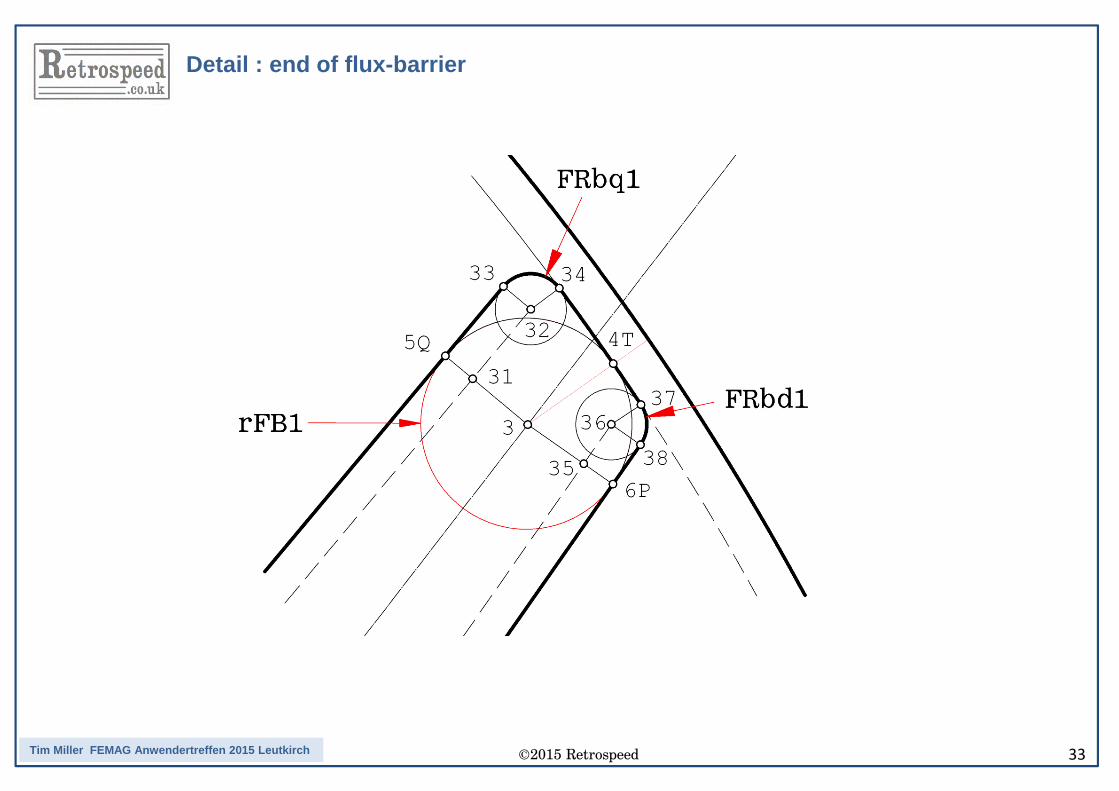
Detail : end of flux-barrier
©2015 Retrospeed 34Tim Miller FEMAG Anwendertreffen 2015 Leutkirch
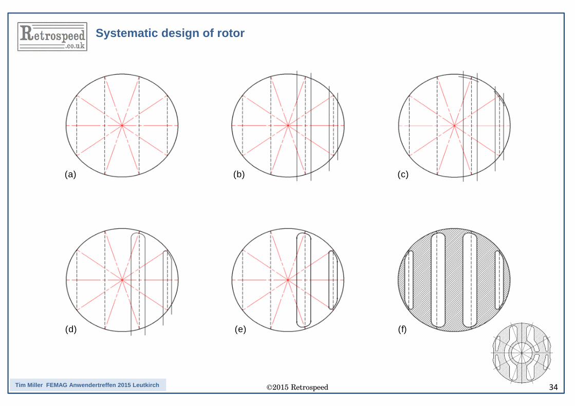
(a) (b)
(d)
(c)
(e) (f)
Systematic design of rotor
©2015 Retrospeed 35Tim Miller FEMAG Anwendertreffen 2015 Leutkirch
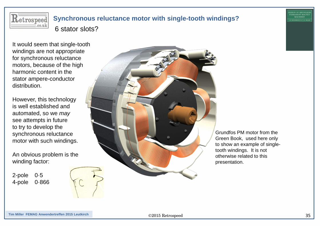
Synchronous reluctance motor with single-tooth windings?
Grundfos PM motor from the Green Book, used here only to show an example of single-tooth windings. It is not otherwise related to this presentation.
It would seem that single-toothwindings are not appropriate for synchronous reluctancemotors, because of the highharmonic content in the stator ampere-conductor distribution.
However, this technology is well established andautomated, so we maysee attempts in futureto try to develop thesynchronous reluctancemotor with such windings.
An obvious problem is thewinding factor:
2-pole 0·54-pole 0·866
6 stator slots?
©2015 Retrospeed 36Tim Miller FEMAG Anwendertreffen 2015 Leutkirch
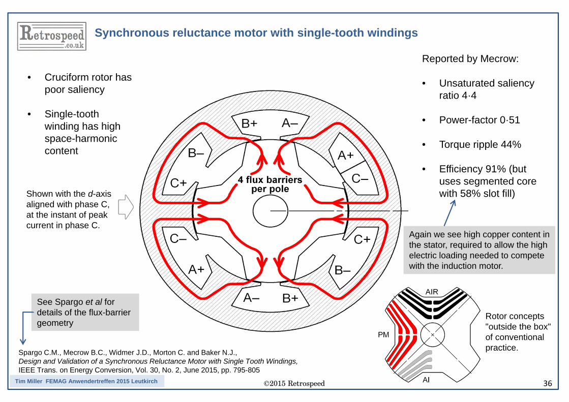
Spargo C.M., Mecrow B.C., Widmer J.D., Morton C. and Baker N.J., Design and Validation of a Synchronous Reluctance Motor with Single Tooth Windings, IEEE Trans. on Energy Conversion, Vol. 30, No. 2, June 2015, pp. 795-805
• Cruciform rotor has poor saliency
• Single-tooth winding has high space-harmonic content
Reported by Mecrow:
• Unsaturated saliency ratio 4·4
• Power-factor 0·51
• Torque ripple 44%
• Efficiency 91% (but uses segmented core with 58% slot fill)
Again we see high copper content in the stator, required to allow the high electric loading needed to compete with the induction motor.
See Spargo et al for details of the flux-barrier geometry
Shown with the d-axis aligned with phase C,at the instant of peak current in phase C.
Synchronous reluctance motor with single-tooth windings
Rotor concepts"outside the box" of conventional practice.
©2015 Retrospeed 37Tim Miller FEMAG Anwendertreffen 2015 Leutkirch
Thank you !
Thank you !
Most of the ideas in this presentation are described in detail in this book:"Reluctance Machines" , 2015, 185 pagesSwitched and synchronous reluctance machines, plus IPM and PM-assistedsynchronous reluctance machines and certain flux-switching machines and variants.Extensive bibliographies are included for both types of machine, with full referencesto the published works mentioned in this presentation.