Embed Size (px)
Citation preview
RE
TU
RN
LIN
E F
ILT
ER
, for h
oriz
on
tal ta
nk
-mo
un
ting
Se
ries
TR
W 3
10
DN
32
PN
10
Sh
ee
t No
.
1068 C
1. T
yp
e in
de
x:
1.1
. Co
mp
lete
filter:
(ord
erin
g e
xa
mp
le)
TR
W.
310.
10V
G.1
6.
S.
P.
-.G
.6.
-.O
.E
21
23
45
67
89
10
11
12
1s
erie
s:
TR
W=
retu
rn-lin
e-filte
r for h
oriz
on
tal ta
nk-m
ou
ntin
g
2n
om
ina
l siz
e: 3
10
3filte
r-ma
teria
l an
d filte
r-fine
ne
ss
:
80
G =
80
µm
, 40
G =
40
µm
,
25
G =
25
µm
sta
inle
ss s
tee
l wire
me
sh
25
VG
= 2
0 µ
m(c
) , 16
VG
= 1
5 µ
m(c
) , 10
VG
= 1
0 µ
m(c
) ,
6 V
G=
7 µ
m(c
) , 3 V
G =
5 µ
m(c
) Inte
rpo
r flee
ce
(gla
ss fib
re)
25
P=
25
µm
, 1
0 P
= 1
0 µ
m p
ap
er
4re
sis
tan
ce
of p
res
su
re d
iffere
nc
e fo
r filter e
lem
en
t:
16
=∆
p 1
6 b
ar
5filte
r ele
me
nt d
es
ign
:
E=
with
ou
t by-p
ass v
alv
eS
=w
ith b
y-p
ass v
alv
e, ∆
p 2
,0 b
ar
6s
ea
ling
ma
teria
l:
P=
Nitrile
(NB
R)
V=
Vito
n (F
PM
)
7filte
r ele
me
nt s
pe
cific
atio
n:
-=
sta
nd
ard
VA
=sta
inle
ss s
tee
l
8c
on
ne
ctio
n:
G=
thre
ad
co
nn
ectio
n a
cco
rdin
g to
DIN
38
52
, T2
9c
on
ne
ctio
n s
ize
:
6=
G 1
¼
10
filter h
ou
sin
g s
pe
cific
atio
n:
-=
sta
nd
ard
11
clo
gg
ing
ind
ica
tor a
t M1
:
-=
with
ou
tO
=vis
ua
l, se
e s
he
et-n
o. 1
61
6E
1=
pre
ssu
re s
witc
h, s
ee
sh
ee
t-no
. 16
16
E2
=p
ressu
re s
witc
h, s
ee
sh
ee
t-no
. 16
16
E5
=p
ressu
re s
witc
h, s
ee
sh
ee
t-no
. 16
16
12
clo
gg
ing
ind
ica
tor a
t M2
:
po
ssib
le in
dic
ato
rs s
ee
po
sitio
n 1
2 o
f the
typ
e in
de
x
1.2
. Filte
r ele
me
nt:
(ord
erin
g e
xa
mp
le)
01E
.320.10V
G.1
6.
S.
P.
-1
23
45
67
1s
erie
s:
01
E.
=filte
r ele
me
nt a
cco
rdin
g to
INT
ER
NO
RM
EN
facto
ry s
pe
cific
atio
n
2n
om
ina
l siz
e: 3
20
3-
7se
e ty
pe
ind
ex-c
om
ple
te filte
r
mo
un
ting
su
rface
su
rface
qu
ality
flatn
ess to
lera
nce
we
igh
t: ap
pro
x. 2
,8 k
g
Ch
an
ge
s o
f me
asu
res a
nd
de
sig
n a
re s
ub
ject to
alte
ratio
n!
ED
V 0
8/0
3
+4
9 - (0
)62
05
- 20
94
-0+
49
- (0)6
20
5 - 2
09
4-4
0p
ho
ne
fax
Frie
de
ns
stra
ss
e 4
1, 6
88
04
Altlu
ss
he
im, G
erm
an
y
e-m
ail
url
sa
les@
inte
rno
rme
n.c
om
ww
w.in
tern
orm
en
.co
m
2. S
pa
re p
arts
:ite
mqty
.desig
natio
ndim
ensio
nartic
le-n
o.
11
filter e
lem
ent
01.E
320
21
filter h
ead
NG
210-3
10
304423
31
filter b
ow
lN
G 3
10
41
scre
w p
lug
M 9
0 x
2316637
51
O-rin
g53 x
4309143 (N
BR
)- (F
PM
)
61
O-rin
g62 x
4308045 (N
BR
)311472 (F
PM
)
72
O-rin
g44 x
6302222 (N
BR
)304384 (F
PM
)
81
O-rin
g88 x
3304417 (N
BR
)310266 (F
PM
)
91
O-rin
g75 x
3302215 (N
BR
)304729 (F
PM
)
10
1O
-ring
82 x
3305191 (N
BR
)305298 (F
PM
)
11
1sheet m
eta
l scre
wD
IN 7
976-F
6,3
x13
316641
12
1clo
ggin
g in
dic
ato
r, vis
ual
O301721
13
1pre
ssure
sw
itch, e
lectric
al
E1, E
2 o
r E5
see s
heet-n
o. 1
616
3. D
es
crip
tion
:R
etu
rn-lin
e filte
rs in
the
TR
W s
erie
s a
re s
uita
ble
for a
wo
rkin
g p
ressu
re u
p to
10
ba
r.P
ressu
re p
ea
ks w
ill be
ab
so
rbe
d b
y a
su
fficie
nt m
arg
in o
f sa
fety
.T
he T
RW
-filters
are
dire
ctly
mounte
d to
the re
serv
oir a
nd c
onnecte
d to
the re
turn
-line. T
he re
turn
-are
a „IN
“ must b
e b
elo
w th
e o
ille
ve
l.T
he filte
r ele
ment c
onsis
ts o
f a s
tar-s
haped, p
leate
d filte
r mate
rial w
hic
h is
supporte
d o
n th
e in
sid
e b
y a
perfo
rate
d c
ore
tub
e a
nd is
bonded to
the e
nd c
aps w
ith a
hig
h-q
uality
adhesiv
e. T
he flo
w is
from
outs
ide to
insid
e. F
ilters
finer th
an 4
0 µ
m s
hould
use th
row
-aw
ay e
lem
ents
made o
f paper o
r Inte
rpor fle
ece (g
lass fib
re). F
ilter e
lem
ents
as fin
e a
s 5
µm
(c) a
re a
vaila
ble
; finer filte
r ele
ments
on
req
ue
st.
INT
ER
NO
RM
EN
-Filte
rs c
an b
e u
sed fo
r petro
leum
-based flu
ids, H
W e
muls
ions, w
ate
r gly
cols
, most s
ynth
etic
fluid
s a
nd lu
bric
atio
nflu
ids. C
on
su
lt facto
ry fo
r sp
ecific
fluid
ap
plic
atio
ns.
INT
ER
NO
RM
EN
-Filte
rs e
lem
ents
are
know
n a
s s
table
ele
ments
whic
h h
ave e
xcelle
nt filtra
tion c
apabilitie
s a
nd a
hig
h d
irt reta
inin
gca
pa
city
, the
refo
re h
avin
g a
lon
g s
erv
ice
life. D
ue
to its
pra
ctic
al d
esig
n, th
e re
turn
-line
filter is
ea
sy to
se
rvic
e.
Wh
en
ch
an
gin
g th
e filte
r ele
me
nt a
de
tach
ab
le c
on
ne
ctio
n b
etw
ee
n th
e filte
r he
ad
an
d th
e filte
r bo
wl p
reve
nts
a flo
w b
ack o
f dirty
oil
into
the
tan
k.
4. T
ec
hn
ica
l da
ta:
tem
pe
ratu
re ra
ng
e:
-10
°C to
+8
0°C
(for a
sh
ort tim
e +
10
0°C
)o
pe
ratin
g m
ed
ium
:m
ine
ral o
il, oth
er m
ed
ia o
n re
qu
est
ma
x. o
pe
ratin
g p
ressu
re:
10
ba
ro
pe
nin
g p
ressu
re b
y-p
ass v
alv
e:
2,0
ba
rco
nn
ectio
n s
yste
m:
thre
ad
co
nn
ectio
n a
cco
rdin
g to
DIN
38
52
, T2
ho
usin
g m
ate
rial:
Al-c
ast, g
lass fib
er re
info
rce
d p
oly
am
ide
se
alin
g m
ate
rial:
Nitrile
(NB
R) o
r Vito
n (F
PM
), oth
er m
ate
rials
on
req
ue
st
insta
llatio
n p
ositio
n:
ve
rtica
lvo
lum
e ta
nk:
1,5
l
Cla
ssifie
d u
nd
er th
e P
ressu
re E
qu
ipm
en
t Dire
ctiv
e 9
7/2
3/E
C fo
r min
era
l oil (flu
id g
rou
p 2
), Artic
le 3
, Pa
ra. 3
.C
lassifie
d u
nd
er A
TE
X D
irectiv
e 9
4/9
/EC
acco
rdin
g to
sp
ecific
ap
plic
atio
n (s
ee
qu
estio
nn
aire
sh
ee
t-no
. 34
27
9-4
).
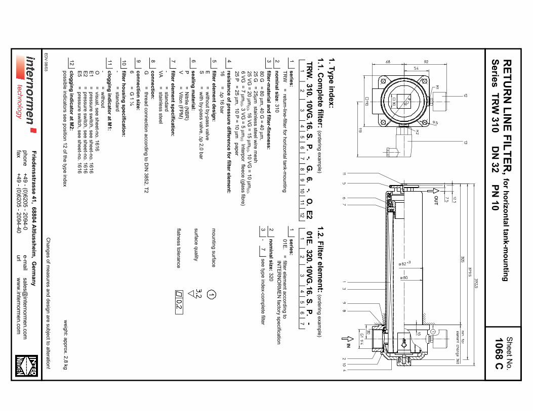
5. S
ym
bo
ls:
with
out in
dic
ato
rw
ith b
y-p
ass v
alv
evis
ual O
ele
ctric
al
conta
ct m
aker
E1
ele
ctric
al
conta
ct b
reaker
E5
ele
ctric
al
conta
ct m
aker/b
reaker
E2
6. P
res
su
re d
rop
flow
cu
rve
s:
Pre
cis
e flo
w ra
tes s
ee
‘INT
-Exp
ert-S
yste
m F
ilter’, re
sp
ectiv
ely
∆p
-cu
rve
s; d
ep
en
din
g
on
filter fin
en
ess a
nd
vis
co
sity
.
7. T
es
t me
tho
ds
:F
ilter e
lem
en
ts a
re te
ste
d a
cco
rdin
g to
the
follo
win
g IS
O s
tan
da
rds:
ISO
29
41
Ve
rifica
tion
of c
olla
pse
/bu
rst re
sis
tan
ce
ISO
29
42
Ve
rifica
tion
of fa
bric
atio
n in
teg
rityIS
O 2
94
3V
erific
atio
n o
f ma
teria
l co
mp
atib
ility w
ith flu
ids
ISO
37
23
Me
tho
d fo
r en
d lo
ad
test
ISO
37
24
Ve
rifica
tion
of flo
w fa
tigu
e c
ha
racte
ristic
sIS
O 3
96
8E
va
lua
tion
of p
ressu
re d
rop
ve
rsu
s flo
w c
ha
racte
ristic
sIS
O 1
68
89
Mu
lti-pa
ss m
eth
od
for e
va
lua
ting
filtratio
n p
erfo
rma
nce
E 1
068 C
RE
TU
RN
LIN
E F
ILT
ER
Se
ries
TE
F 4
1 D
N 1
6 P
N 1
0
1. T
yp
e in
de
x:
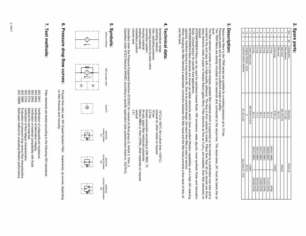
1.1
. Co
mp
lete
filter:
(ord
erin
g e
xa
mp
le)
TE
F.41.1
0V
G.1
6.S
.P
.-.
G.
3.
-.E
1.O
12
34
56
78
910
11
12
TE
F.41.1
0V
G.3
0.E
.P
.-.
G.
3.
-.E
1.
O1
23
45
67
89
10
11
12
1s
erie
s:
TE
F=
tan
k-m
ou
nte
d re
turn
-line
-filter
2n
om
ina
l siz
e: 4
1
3filte
r-ma
teria
l an
d filte
r-fine
ne
ss
:
80
G =
80
µm
,4
0 G
= 4
0 µ
m,
25
G =
25
µm
sta
inle
ss s
teel w
ire m
esh
25
VG
= 2
0 µ
m(c
) , 16
VG
= 1
5 µ
m(c
) , 10
VG
= 1
0 µ
m(c
) , 6 V
G =
7 µ
m(c
) ,
3 V
G =
5 µ
m(c
) Inte
rpo
r flee
ce
(gla
ss fib
re)
25
P =
25
µm
, 1
0 P
= 1
0 µ
m
pa
pe
r on
ly w
ith 0
1E
.41
4re
sis
tan
ce
of p
res
su
re d
iffere
nc
e fo
r filter e
lem
en
t:
16
=0
1E
.41
for ∆
p 1
6 b
ar (s
tan
da
rd w
ith b
y-p
ass v
alv
e)
30
=0
1E
.60
for ∆
p 3
0 b
ar (s
tan
da
rd w
itho
ut b
y-p
ass v
alv
e)
5filte
r ele
me
nt d
es
ign
:
E=
with
ou
t by-p
ass v
alv
e ( 0
1E
.60
)S
=w
ith b
y-p
ass v
alv
e ( 0
1E
.41
) ∆p
2,0
ba
r
6s
ea
ling
ma
teria
l:
P=
Nitrile
(NB
R)
V=
Vito
n (F
PM
)
7filte
r ele
me
nt s
pe
cific
atio
n: (s
ee
ca
talo
g)
-=
sta
nd
ard
VA
=sta
inle
ss s
tee
lIS
06
=se
e s
he
et-n
o. 3
16
01
8c
on
ne
ctio
n:
G=
thre
ad
co
nn
ectio
n a
cco
rdin
g to
DIN
38
52
, T2
9c
on
ne
ctio
n s
ize
:
3=
G ½
10
filter h
ou
sin
g s
pe
cific
atio
n: (s
ee
ca
talo
g)
-=
sta
nd
ard
IS0
6=
se
e s
he
et-n
o. 3
16
05
11
clo
gg
ing
ind
ica
tor a
t M1
:
-=
with
ou
tO
=vis
ua
l, se
e s
he
et-n
o. 1
61
6E
1=
pre
ssu
re s
witc
h, s
ee
sh
ee
t-no
. 16
16
E2
=p
ressu
re s
witc
h, s
ee
sh
ee
t-no
. 16
16
E5
=p
ressu
re s
witc
h, s
ee
sh
ee
t-no
. 16
16
12
clo
gg
ing
ind
ica
tor a
t M2
:
po
ssib
le in
dic
ato
rs s
ee
po
sitio
n 1
1 o
f the
typ
e in
de
x
1.2
. Filte
r ele
me
nt:
(ord
erin
g e
xa
mp
le)
01E
.41.10V
G.1
6.S
.P
.-
12
34
56
7
01E
.60.10V
G.3
0.E
.P
.-
12
34
56
7
1s
erie
s:
01
E.
=filte
r ele
ment a
ccord
ing to
INT
ER
NO
RM
EN
facto
ry specific
atio
n
2n
om
ina
l siz
e: 4
1, 6
0
3-
7se
e ty
pe
ind
ex-c
om
ple
te filte
r
we
igh
t: 0,8
kg
Ch
an
ge
s o
f me
asu
res a
nd
de
sig
n a
re s
ub
ject to
alte
ratio
n!
Sh
ee
t No
.
1040 D
Wh
en
eq
uip
ed
with
on
e c
log
gin
g in
dic
ato
r use
pre
fera
bly
co
nn
ectio
n M
1.
ED
V 0
8/0
3
(filter w
ith b
y-p
ass v
alv
e)
(filter w
itho
ut
by-p
ass v
alv
e)
( with
by-p
ass v
alv
e)
( with
ou
t by-p
ass v
alv
e)
+4
9 - (0
)62
05
- 20
94
-0+
49
- (0)6
20
5 - 2
09
4-4
0p
ho
ne
fax
Frie
de
ns
stra
ss
e 4
1, 6
88
04
Altlu
ss
he
im, G
erm
an
y
e-m
ail
url
sa
les@
inte
rno
rme
n.c
om
ww
w.in
tern
orm
en
.co
m

2. S
pa
re p
arts
:ite
mqty
.desig
natio
ndim
ensio
nartic
le-n
o.
11
filter e
lem
ent w
ith b
y-p
ass
01.E
41
1filte
r ele
ment w
ithout b
y-p
ass
01.E
60
21
filter h
ead
TE
F 4
1 - 5
5305458
31
filter c
over
M 6
0 x
2303621
41
filter b
ow
lT
EF
41
306673
52
O-rin
g56 x
3305072 (N
BR
)305322 (F
PM
)
61
O-rin
g50 x
2,5
305239 (N
BR
)305321 (F
PM
)
71
O-rin
g22 x
3,5
304341 (N
BR
)304392 (F
PM
)
81
sprin
gD
A =
40
304982
91
clo
ggin
g in
dic
ato
r vis
ual
O301721
10
1clo
ggin
g in
dic
ato
r ele
ctric
al
E1, E
2 o
r E5
see s
heet-n
o. 1
616
3. D
es
crip
tion
:R
etu
rn-lin
e filte
rs in
the
TE
F s
erie
s a
re s
uita
ble
for a
wo
rkin
g p
ressu
re u
p to
10
ba
r.P
ressu
re p
ea
ks w
ill be
ab
so
rbe
d b
y a
su
fficie
nt m
arg
in o
f sa
fety
.T
he
TE
F-filte
rs a
re d
irectly
mo
un
ted
to th
e re
se
rvo
ir an
d c
on
ne
cte
d to
the
retu
rn-lin
e.
The filte
r ele
ment c
onsis
ts o
f a s
tar-s
haped, p
leate
d filte
r mate
rial w
hic
h is
supporte
d o
n th
e in
sid
e b
y a
perfo
rate
d c
ore
tub
e a
nd is
bonded to
the e
nd c
aps w
ith a
hig
h-q
uality
adhesiv
e. T
he flo
w is
from
outs
ide to
insid
e. F
ilters
finer th
an 4
0 µ
m s
hould
use th
row
-aw
ay e
lem
ents
made o
f paper o
r Inte
rpor fle
ece (g
lass fib
re). F
ilter e
lem
ents
as fin
e a
s 5
µm
(c) m
icro
ns a
re a
vaila
ble
; finer filte
re
lem
en
ts o
n re
qu
est.
INT
ER
NO
RM
EN
-Filte
rs c
an b
e u
sed fo
r petro
leum
-based flu
ids, H
W e
muls
ions, w
ate
r gly
cols
, most s
ynth
etic
fluid
s a
nd lu
bric
atio
nflu
ids. C
on
su
lt facto
ry fo
r sp
ecific
fluid
ap
plic
atio
ns.
INT
ER
NO
RM
EN
-Filte
rs e
lem
ents
are
know
n a
s s
table
ele
ments
whic
h h
ave e
xcelle
nt filtra
tion c
apabilitie
s a
nd a
hig
h d
irt reta
inin
gca
pa
city
, the
refo
re h
avin
g a
lon
g s
erv
ice
life. D
ue
to its
pra
ctic
al d
esig
n, th
e re
turn
-line
filter is
ea
sy to
se
rvic
e.
Wh
en
ch
an
gin
g th
e filte
r ele
me
nt a
de
tach
ab
le c
on
ne
ctio
n b
etw
ee
n th
e filte
r he
ad
an
d th
e filte
r bo
wl p
reve
nts
a flo
w b
ack o
f dirty
oil
into
the
tan
k.
4. T
ec
hn
ica
l da
ta:
tem
pe
ratu
re ra
ng
e:
-10
°C to
+8
0°C
(for a
sh
ort tim
e +
10
0°C
)o
pe
ratin
g m
ed
ium
:m
ine
ral o
il, oth
er m
ed
ia o
n re
qu
est
ma
x. o
pe
ratin
g p
ressu
re:
10
ba
ro
pe
nin
g p
ressu
re b
y-p
ass v
alv
e:
2,0
ba
rco
nn
ectio
n s
yste
m:
thre
ad
co
nn
ectio
n a
cco
rdin
g to
DIN
38
52
, T2
ho
usin
g m
ate
rial:
Al-c
ast, g
lass fib
er re
info
rce
d p
oly
am
ide
se
alin
g m
ate
rial:
Nitrile
(NB
R) o
r Vito
n (F
PM
), oth
er m
ate
rials
on
req
ue
st
insta
llatio
n p
ositio
n:
ve
rtica
lvo
lum
e ta
nk:
0,2
l
Cla
ssifie
d u
nd
er th
e P
ressu
re E
qu
ipm
en
t Dire
ctiv
e 9
7/2
3/E
C fo
r min
era
l oil (flu
id g
rou
p 2
), Artic
le 3
, Pa
ra. 3
.C
lassifie
d u
nd
er A
TE
X D
irectiv
e 9
4/9
/EC
acco
rdin
g to
sp
ecific
ap
plic
atio
n (s
ee
qu
estio
nn
aire
sh
ee
t-no
. 34
27
9-4
).
5. S
ym
bo
ls:
with
out in
dic
ato
rw
ith b
y-p
ass v
alv
evis
ual O
ele
ctric
al
conta
ct m
aker
E1
ele
ctric
al
conta
ct b
reaker
E5
ele
ctric
al
conta
ct m
aker/b
reaker
E2
6. P
res
su
re d
rop
flow
cu
rve
s:
Pre
cis
e flo
w ra
tes s
ee
‘INT
-Exp
ert-S
yste
m F
ilter’, re
sp
ectiv
ely
∆p
-cu
rve
s; d
ep
en
din
g
on
filter fin
en
ess a
nd
vis
co
sity
.
7. T
es
t me
tho
ds
:F
ilter e
lem
en
ts a
re te
ste
d a
cco
rdin
g to
the
follo
win
g IS
O s
tan
da
rds:
ISO
29
41
Ve
rifica
tion
of c
olla
pse
/bu
rst re
sis
tan
ce
ISO
29
42
Ve
rifica
tion
of fa
bric
atio
n in
teg
rityIS
O 2
94
3V
erific
atio
n o
f ma
teria
l co
mp
atib
ility w
ith flu
ids
ISO
37
23
Me
tho
d fo
r en
d lo
ad
test
ISO
37
24
Ve
rifica
tion
of flo
w fa
tigu
e c
ha
racte
ristic
sIS
O 3
96
8E
va
lua
tion
of p
ressu
re d
rop
ve
rsu
s flo
w c
ha
racte
ristic
sIS
O 1
68
89
Mu
lti-pa
ss m
eth
od
for e
va
lua
ting
filtratio
n p
erfo
rma
nce
E 1
040 D
RE
TU
RN
LIN
E F
ILT
ER
with
bre
ath
er filte
r
Se
ries
TE
FB
41
DN
16
PN
10
Sh
ee
t No
.
1041 E
1. T
yp
e in
de
x:
1.1
. Co
mp
lete
filter:
(ord
erin
g e
xa
mp
le)
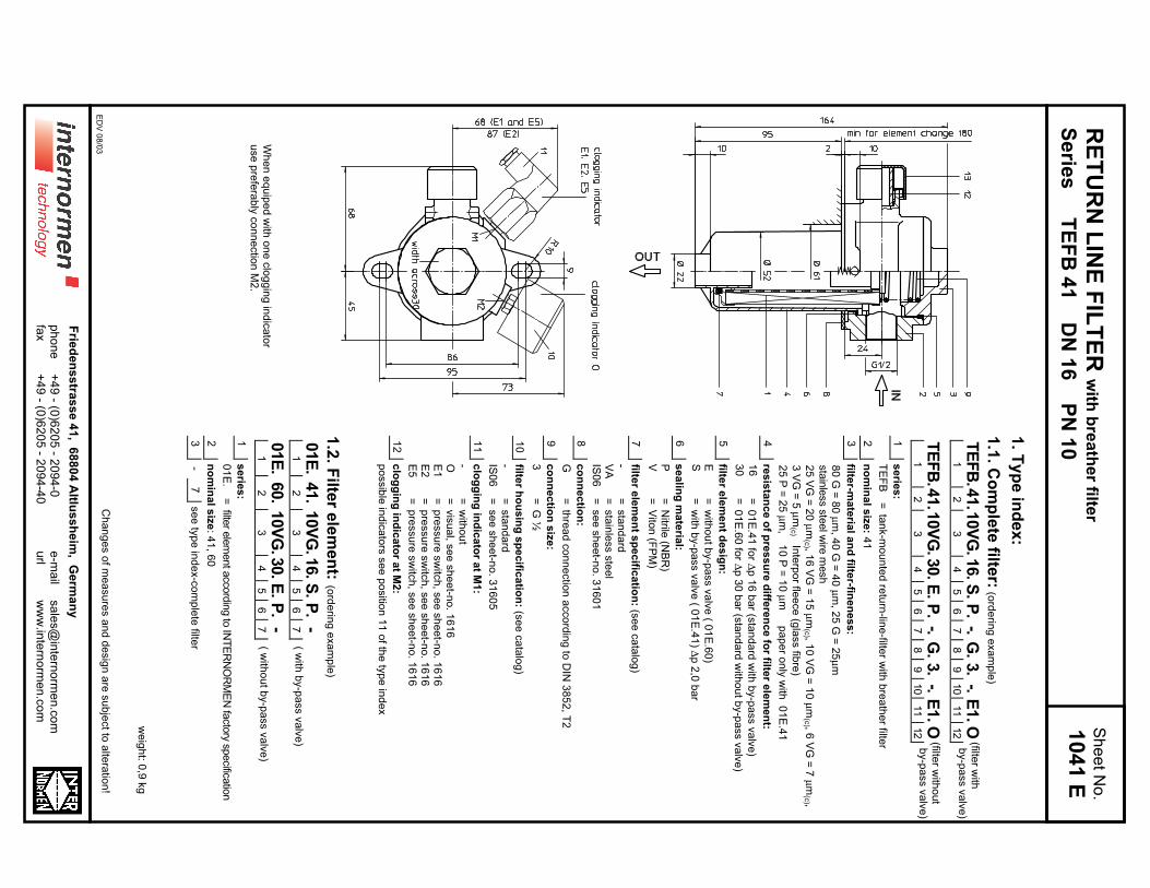
TE
FB
.41.1
0V
G.1
6.S
.P
.-.
G.
3.
-.E
1.O
12
34
56
78
910
11
12
TE
FB
.41.1
0V
G.3
0.E
.P
.-.
G.
3.
-.E
1.O
12
34
56
78
910
11
12
1s
erie
s:
TE
FB
=ta
nk-m
ou
nte
d re
turn
-line
-filter w
ith b
rea
the
r filter
2n
om
ina
l siz
e: 4
1
3filte
r-ma
teria
l an
d filte
r-fine
ne
ss
:
80
G =
80
µm
, 40
G =
40
µm
, 25
G =
25
µm
sta
inle
ss s
teel w
ire m
esh
25
VG
= 2
0 µ
m(c
) , 16
VG
= 1
5 µ
m(c
) , 10
VG
= 1
0 µ
m(c
) , 6 V
G =
7 µ
m(c
) ,
3 V
G =
5 µ
m(c
) Inte
rpo
r flee
ce
(gla
ss fib
re)
25
P =
25
µm
, 1
0 P
= 1
0 µ
m
pa
pe
r on
ly w
ith 0
1E
.41
4re
sis
tan
ce
of p
res
su
re d
iffere
nc
e fo
r filter e
lem
en
t:
16
=0
1E
.41
for ∆
p 1
6 b
ar (s
tan
da
rd w
ith b
y-p
ass v
alv
e)
30
=0
1E
.60
for ∆
p 3
0 b
ar (s
tan
da
rd w
itho
ut b
y-p
ass v
alv
e)
5filte
r ele
me
nt d
es
ign
:
E=
with
ou
t by-p
ass v
alv
e ( 0
1E
.60
)S
=w
ith b
y-p
ass v
alv
e ( 0
1E
.41
) ∆p
2,0
ba
r
6s
ea
ling
ma
teria
l:
P=
Nitrile
(NB
R)
V=
Vito
n (F
PM
)
7filte
r ele
me
nt s
pe
cific
atio
n: (s
ee
ca
talo
g)
-=
sta
nd
ard
VA
=sta
inle
ss s
tee
lIS
06
=se
e s
he
et-n
o. 3
16
01
8c
on
ne
ctio
n:
G=
thre
ad
co
nn
ectio
n a
cco
rdin
g to
DIN
38
52
, T2
9c
on
ne
ctio
n s
ize
:
3=
G ½
10
filter h
ou
sin
g s
pe
cific
atio
n: (s
ee
ca
talo
g)
-=
sta
nd
ard
IS0
6=
se
e s
he
et-n
o. 3
16
05
11
clo
gg
ing
ind
ica
tor a
t M1
:
-=
with
ou
tO
=vis
ua
l, se
e s
he
et-n
o. 1
61
6E
1=
pre
ssu
re s
witc
h, s
ee
sh
ee
t-no
. 16
16
E2
=p
ressu
re s
witc
h, s
ee
sh
ee
t-no
. 16
16
E5
=p
ressu
re s
witc
h, s
ee
sh
ee
t-no
. 16
16
12
clo
gg
ing
ind
ica
tor a
t M2
:
po
ssib
le in
dic
ato
rs s
ee
po
sitio
n 1
1 o
f the
typ
e in
de
x
1.2
. Filte
r ele
me
nt:
(ord
erin
g e
xa
mp
le)
01E
.41.
10V
G.1
6.S
.P
.-
12
34
56
7
01E
.60.
10V
G.3
0.E
.P
.-
12
34
56
7
1s
erie
s:
01
E.
=filte
r ele
ment a
ccord
ing to
INT
ER
NO
RM
EN
facto
ry specific
atio
n
2n
om
ina
l siz
e: 4
1, 6
0
3-
7se
e ty
pe
ind
ex-c
om
ple
te filte
r
we
igh
t: 0,9
kg
Ch
an
ge
s o
f me
asu
res a
nd
de
sig
n a
re s
ub
ject to
alte
ratio
n!
ED
V 0
8/0
3
Wh
en
eq
uip
ed
with
on
e c
log
gin
g in
dic
ato
ru
se
pre
fera
bly
co
nn
ectio
n M
2.
(filter w
ith b
y-p
ass v
alv
e)
(filter w
itho
ut
by-p
ass v
alv
e)
( with
by-p
ass v
alv
e)
( with
ou
t by-p
ass v
alv
e)
+4
9 - (0
)62
05
- 20
94
-0+
49
- (0)6
20
5 - 2
09
4-4
0p
ho
ne
fax
Frie
de
ns
stra
ss
e 4
1, 6
88
04
Altlu
ss
he
im, G
erm
an
y
e-m
ail
url
sa
les@
inte
rno
rme
n.c
om
ww
w.in
tern
orm
en
.co
m
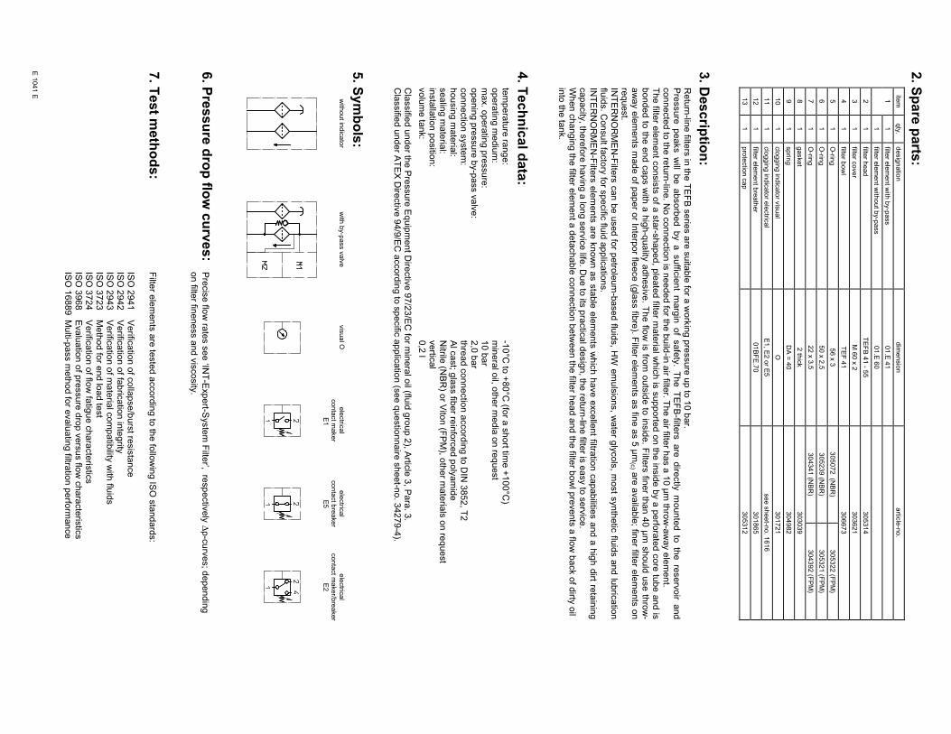
2. S
pa
re p
arts
:ite
mqty
.desig
natio
ndim
ensio
nartic
le-n
o.
11
filter e
lem
ent w
ith b
y-p
ass
01.E
41
1filte
r ele
ment w
ithout b
y-p
ass
01.E
60
21
filter h
ead
TE
FB
41 - 5
5305314
31
filter c
over
M 6
0 x
2303621
41
filter b
ow
lT
EF
41
306673
51
O-rin
g56 x
3305072 (N
BR
)305322 (F
PM
)
61
O-rin
g50 x
2,5
305239 (N
BR
)305321 (F
PM
)
71
O-rin
g22 x
3,5
304341 (N
BR
)304392 (F
PM
)
81
gasket
2 th
ick
303039
91
sprin
gD
A =
40
304982
10
1clo
ggin
g in
dic
ato
r vis
ual
O301721
11
1clo
ggin
g in
dic
ato
r ele
ctric
al
E1, E
2 o
r E5
see s
heet-n
o. 1
616
12
1filte
r ele
ment b
reath
er
01B
FE
.70
301865
13
1pro
tectio
n c
ap
305312
3. D
es
crip
tion
:R
etu
rn-lin
e filte
rs in
the
TE
FB
se
ries a
re s
uita
ble
for a
wo
rkin
g p
ressu
re u
p to
10
ba
r.P
ressure
peaks w
ill be absorb
ed by a suffic
ient
marg
in of
safe
ty.
The T
EF
B-filte
rs are
dire
ctly
m
ounte
d to
th
e re
serv
oir
and
co
nn
ecte
d to
the
retu
rn-lin
e. N
o c
on
ne
ctio
n is
ne
ed
ed
for th
e b
uild
-in a
ir filter. T
he
air filte
r ha
s a
10
µm
thro
w-a
wa
y e
lem
en
t.T
he filte
r ele
ment c
onsis
ts o
f a s
tar-s
haped, p
leate
d filte
r mate
rial w
hic
h is
supporte
d o
n th
e in
sid
e b
y a
perfo
rate
d c
ore
tub
e a
nd is
bonded to
the e
nd c
aps w
ith a
hig
h-q
uality
adhesiv
e. T
he flo
w is
from
outs
ide to
insid
e. F
ilters
finer th
an 4
0 µ
m s
hould
use th
row
-aw
ay e
lem
ents
made o
f paper o
r Inte
rpor fle
ece (g
lass fib
re). F
ilter e
lem
ents
as fin
e a
s 5
µm
(c) a
re a
vaila
ble
; finer filte
r ele
ments
on
req
ue
st.
INT
ER
NO
RM
EN
-Filte
rs c
an b
e u
sed fo
r petro
leum
-based flu
ids, H
W e
muls
ions, w
ate
r gly
cols
, most s
ynth
etic
fluid
s a
nd lu
bric
atio
nflu
ids. C
on
su
lt facto
ry fo
r sp
ecific
fluid
ap
plic
atio
ns.
INT
ER
NO
RM
EN
-Filte
rs e
lem
ents
are
know
n a
s s
table
ele
ments
whic
h h
ave e
xcelle
nt filtra
tion c
apabilitie
s a
nd a
hig
h d
irt reta
inin
gca
pa
city
, the
refo
re h
avin
g a
lon
g s
erv
ice
life. D
ue
to its
pra
ctic
al d
esig
n, th
e re
turn
-line
filter is
ea
sy to
se
rvic
e.
Wh
en
ch
an
gin
g th
e filte
r ele
me
nt a
de
tach
ab
le c
on
ne
ctio
n b
etw
ee
n th
e filte
r he
ad
an
d th
e filte
r bo
wl p
reve
nts
a flo
w b
ack o
f dirty
oil
into
the
tan
k.
4. T
ec
hn
ica
l da
ta:
tem
pe
ratu
re ra
ng
e:
-10
°C to
+8
0°C
(for a
sh
ort tim
e +
10
0°C
)o
pe
ratin
g m
ed
ium
:m
ine
ral o
il, oth
er m
ed
ia o
n re
qu
est
ma
x. o
pe
ratin
g p
ressu
re:
10
ba
ro
pe
nin
g p
ressu
re b
y-p
ass v
alv
e:
2,0
ba
rco
nn
ectio
n s
yste
m:
thre
ad
co
nn
ectio
n a
cco
rdin
g to
DIN
38
52
, T2
ho
usin
g m
ate
rial:
Al c
ast; g
lass fib
er re
info
rce
d p
oly
am
ide
se
alin
g m
ate
rial:
Nitrile
(NB
R) o
r Vito
n (F
PM
), oth
er m
ate
rials
on
req
ue
st
insta
llatio
n p
ositio
n:
ve
rtica
lvo
lum
e ta
nk:
0,2
l
Cla
ssifie
d u
nd
er th
e P
ressu
re E
qu
ipm
en
t Dire
ctiv
e 9
7/2
3/E
C fo
r min
era
l oil (flu
id g
rou
p 2
), Artic
le 3
, Pa
ra. 3
.C
lassifie
d u
nd
er A
TE
X D
irectiv
e 9
4/9
/EC
acco
rdin
g to
sp
ecific
ap
plic
atio
n (s
ee
qu
estio
nn
aire
sh
ee
t-no
. 34
27
9-4
).
5. S
ym
bo
ls:
with
out in
dic
ato
rw
ith b
y-p
ass v
alv
evis
ual O
ele
ctric
al
conta
ct m
aker
E1
ele
ctric
al
conta
ct b
reaker
E5
ele
ctric
al
conta
ct m
aker/b
reaker
E2
6. P
res
su
re d
rop
flow
cu
rve
s:
Pre
cis
e flo
w ra
tes s
ee
‘INT
-Exp
ert-S
yste
m F
ilter’, re
sp
ectiv
ely
∆p
-cu
rve
s; d
ep
en
din
g
on
filter fin
en
ess a
nd
vis
co
sity
.
7. T
es
t me
tho
ds
:F
ilter e
lem
en
ts a
re te
ste
d a
cco
rdin
g to
the
follo
win
g IS
O s
tan
da
rds:
ISO
29
41
Ve
rifica
tion
of c
olla
pse
/bu
rst re
sis
tan
ce
ISO
29
42
Ve
rifica
tion
of fa
bric
atio
n in
teg
rityIS
O 2
94
3V
erific
atio
n o
f ma
teria
l co
mp
atib
ility w
ith flu
ids
ISO
37
23
Me
tho
d fo
r en
d lo
ad
test
ISO
37
24
Ve
rifica
tion
of flo
w fa
tigu
e c
ha
racte
ristic
sIS
O 3
96
8E
va
lua
tion
of p
ressu
re d
rop
ve
rsu
s flo
w c
ha
racte
ristic
sIS
O 1
68
89
Mu
lti-pa
ss m
eth
od
for e
va
lua
ting
filtratio
n p
erfo
rma
nce
E 1
041 E
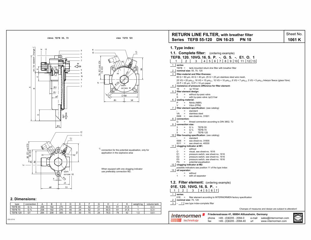
RETURN LINE FILTER, with breather filter
Series TEFB 55-120 DN 16-25 PN 10
Sheet No.
1061 K
1. Type index:
1.1. Complete filter: (ordering example)
TEFB. 120. 10VG. 16. S. P. -. G. 5. -. E1. O. 11 2 3 4 5 6 7 8 9 10 11 12 13
1 series:
TEFB = tank-mounted return-line filter with breather filter
2 nominal size: 55, 70, 120
3 filter-material and filter-fineness:
80 G = 80 µm, 40 G = 40 µm, 25 G = 25 µm stainless steel wire mesh,
25 VG = 20 µm(c), 16 VG = 15 µm(c), 10 VG = 10 µm(c), 6 VG = 7 µm(c), 3 VG = 5 µm(c) Interpor fleece (glass f ibre)
25 P = 25 µm, 10 P = 10 µm paper
4 resistance of pressure difference for filter element:
16 = ∆p 16 bar
5 filter element design:
E = without by-pass valve
S = with by-pass valve ∆p2,0 bar
6 sealing material:
P = Nitrile (NBR)
V = Viton (FPM)
7 filter element specification: (see catalog)
- = standard
VA = stainless steel
IS06 = see sheet-no. 31601
8 connection:
G = thread connection according to DIN 3852, T2
9 connection size:
3 = G ½ TEFB 55
4 = G ¾ TEFB 70
5 = G1 TEFB 120
10 filter housing specification: (see catalog)
- = standard
IS06 = see sheet-no. 31605
IS11 = see sheet-no. 40530
11 clogging indicator at M1:
- = without
O = visual, see sheet-no. 1616
E1 = pressure switch, see sheet-no. 1616
E2 = pressure switch, see sheet-no. 1616
E5 = pressure switch, see sheet-no. 1616
PA = potential equalisation
12 clogging indicator at M2:
possible indicators see position 11 of the type index
13 oil separator:
- = without
1 = with oil separator
1.2. Filter element: (ordering example)
01E. 120. 10VG. 16. S. P. -1 2 3 4 5 6 7
1 series:
01E. = filter element according to INTERNORMEN factory specification
2 nominal size: 70, 120
3 - 7 see type index-complete filter
Changes of measures and design are subject to alteration!
2. Dimensions:
type connection A B C D E F G H J K weight kg volume tank
TEFB 55 G ½ 258 192 270 45 24 52 21 60,5 61 31,5 1 0,3 l
TEFB 70 G ¾ 258 192 270 45 24 52 21 60,5 61 31,5 1 0,3 l
TEFB 120 G1 284 208 300 65 30 70 24 78,5 79 42 1,5 0,6 l
EDV 07/10
When equiped with one clogging indicator
use preferably connection M2.
phonefax
+49 - (0)6205 - 2094-0+49 - (0)6205 - 2094-40
Friedensstrasse 41, 68804 Altlussheim, Germany
e-mailurl
1) connection for the potential equalisation, only for
application in the explosive area
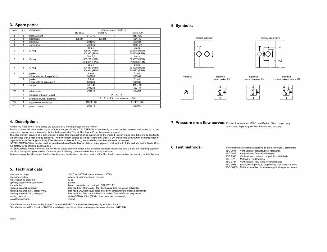
3. Spare parts:
item qty. designation dimension and article-no.
TEFB 55 TEFB 70 TEFB 120
1 1 filter element 01E. 70 01E. 120
2 1 filter head 305314 305315 304743
3 1 filter bowl 304595 303041
4 1 screw plug M 60 x 2 M 82 x 2
56 x 3 75 x 3
5 1 O-ring 305072 /NBR) 302215 (NBR)
305322 (FPM) 304729 (FPM)
50 x 2,5 68 x 4
6 1 O-ring 305239 (NBR) 303037 (NBR)
305321 (FPM) 313046 (FPM)
22 x 3 24 x 3
7 1 O-ring 304387 (NBR) 303038 (NBR)
304931 (FPM) 304397 (FPM)
8 1 gasket 2 thick 3 thick
( filter without oil separator ) 307706 303039
1 gasket 2 thick 3 thick
( filter with oil separator ) 306786 303039
9 1 spring DA = 40
304982
DA = 52
302144
10 1 oil separator 304544 310261
11 1 clogging indicator, visual O 301721
12 1 pressure switch, electrical E1, E2 or E5 see sheet-no. 1616
13 1 filter element breather 01BFE. 70 01BFE. 120
14 1 protection cap 305312 303048
4. Description:
Return-line filters in the TEFB series are suitable for a working pressure up to 10 bar.
Pressure peaks will be absorbed by a sufficient margin of safety. The TEFB-filters are directly mounted to the reservoir and connected to the
return-line. No connection is needed for the build-in air filter. The air filter has a 10 µm throw-away element.
The filter element consists of a star-shaped, pleated filter material which is supported on the inside by a perforated core tube and is bonded to
the end caps with a high-quality adhesive. The flow is from outside to inside. Filters finer than 40 µm should use throw-away elements made of
paper or Interpor fleece (glass fibre). Filter elements as fine as 5 µm (c) are available; finer filter elements on request.
INTERNORMEN-Filters can be used for petroleum-based fluids, HW emulsions, water glycols, most synthetic fluids and lubrication fluids. Con-
sult factory for specific fluid applications.
INTERNORMEN-Filters elements are known as stable elements which have excellent filtration capabilities and a high dirt retaining capacity,
therefore having a long service life. Due to its practical design, the return-line filter is easy to service.
When changing the filter element a detachable connection between the filter head and the filter bowl prevents a flow back of dirty oil into the tank.
5. Technical data:
temperature range: - 10°C to + 80°C (for a short time + 100°C)
operating medium: mineral oil, other media on request
max. operating pressure: 10 bar
opening pressure by-pass valve: 2,0 bar
line adapter: thread connection according to DIN 3852, T2
housing material standard: filter head AL , filter cover / filter bowl glass fibre reinforced polyamide
housing material IS11, category M2: filter head GG, filter cover steel, filter bowl carbon fibre reinforced polyamide
housing material IS11, category 2: filter head AL, filter cover / filter bowl carbon fibre reinforced polyamide
sealing material: Nitrile (NBR) or Viton (FPM), other materials on request
installation position: vertical
Classified under the Pressure Equipment Directive 97/23/EC for mineral oil (fluid group 2), Article 3, Para. 3.
Classified under ATEX Directive 94/9/EC according to specific application (see questionnaire sheet-no. 34279-4).
E 1061 K
6. Symbols:
without indicator with by-pass valve
visual O electrical
contact maker E1
electrical
contact breaker E5
electrical
contact maker/breaker E2
7. Pressure drop flow curves: Precise flow rates see ‘INT-Expert-System Filter’, respectively
∆p- curves; depending on filter fin eness and viscosity.
8. Test methods: Filter elements are tested according to the following ISO standards:
ISO 2941 Verification of collapse/burst resistance
ISO 2942 Verification of fabrication integrity
ISO 2943 Verification of material compatibility with fluids
ISO 3723 Method for end load test
ISO 3724 Verification of flow fatigue characteristics
ISO 3968 Evaluation of pressure drop versus flow charact eristics
ISO 16889 Multi-pass method for evaluating filtration perfo rmance
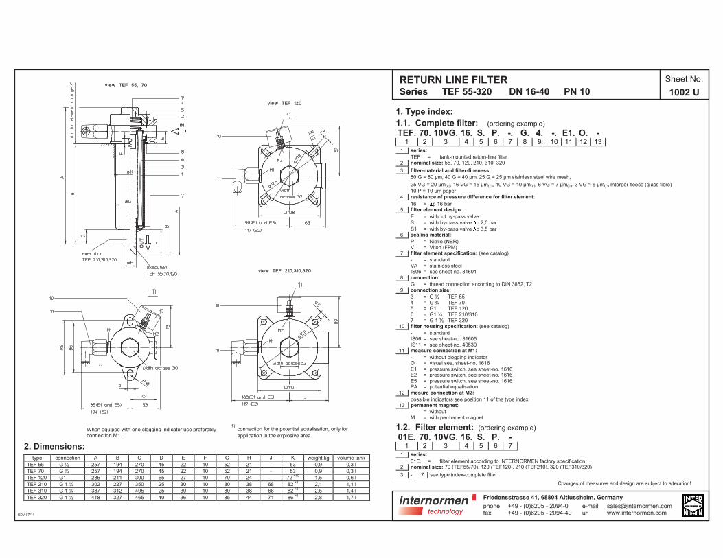
RETURN LINE FILTERSeries TEF 55-320 DN 16-40 PN 10
Sheet No.
1002 U
2. Dimensions:
type connection A B C D E F G H J K weight kg volume tank
TEF 55 G ½ 257 194 270 45 22 10 52 21 - 53 0,9 0,3 l
TEF 70 G ¾ 257 194 270 45 22 10 52 21 - 53 0,9 0,3 l
TEF 120 G1 285 211 300 65 27 10 70 24 - 72+10
1,5 0,6 l
TEF 210 G 1 ¼ 302 227 350 25 30 10 80 38 68 82+3
2,1 1,1 l
TEF 310 G 1 ¼ 387 312 405 25 30 10 80 38 68 82+3
2,5 1,4 l
TEF 320 G 1 ½ 418 327 465 40 36 10 85 44 71 86+6
2,8 1,7 l
EDV 07/11
1. Type index:
1.1. Complete filter: (ordering example)
TEF. 70. 10VG. 16. S. P. -. G. 4. -. E1. O. -1 2 3 4 5 6 7 8 9 10 11 12 13
1 series:
TEF = tank-mounted return-line filter2 nominal size: 55, 70, 120, 210, 310, 320
3 filter-material and filter-fineness:
80 G = 80 µm, 40 G = 40 µm, 25 G = 25 µm stainless steel wire mesh,
25 VG = 20 µm(c), 16 VG = 15 µm(c), 10 VG = 10 µm(c), 6 VG = 7 µm(c), 3 VG = 5 µm(c) Interpor fleece (glass fibre)
10 P = 10 µm paper4 resistance of pressure difference for filter element:
16 = p 16 bar5 filter element design:
E = without by-pass valve
S = with by-pass valve p 2,0 bar
S1 = with by-pass valve p 3,5 bar6 sealing material:
P = Nitrile (NBR)V = Viton (FPM)
7 filter element specification: (see catalog)
- = standardVA = stainless steelIS06 = see sheet-no. 31601
8 connection:
G = thread connection according to DIN 3852, T29 connection size:
3 = G ½ TEF 554 = G ¾ TEF 705 = G1 TEF 1206 = G1 ¼ TEF 210/3107 = G 1 ½ TEF 320
10 filter housing specification: (see catalog)
- = standardIS06 = see sheet-no. 31605IS11 = see sheet-no. 40530
11 measure connection at M1:
- = without clogging indicatorO = visual see, sheet-no. 1616E1 = pressure switch, see sheet-no. 1616E2 = pressure switch, see sheet-no. 1616E5 = pressure switch, see sheet-no. 1616PA = potential equalisation
12 mesure connection at M2:
possible indicators see position 11 of the type index13 permanent magnet:
- = withoutM = with permanent magnet
1.2. Filter element: (ordering example)
01E. 70. 10VG. 16. S. P. -1 2 3 4 5 6 7
1 series:
01E. = filter element according to INTERNORMEN factory specification2 nominal size: 70 (TEF55/70), 120 (TEF120), 210 (TEF210), 320 (TEF310/320)
3 - 7 see type index-complete filter
Changes of measures and design are subject to alteration!
When equiped with one clogging indicator use preferably connection M1.
1)connection for the potential equalisation, only for
application in the explosive area
phonefax
+49 - (0)6205 - 2094-0+49 - (0)6205 - 2094-40
Friedensstrasse 41, 68804 Altlussheim, Germany
e-mailurl

6. Symbols:
without indicator with by-pass valve
visual O electricalcontact maker E1
electricalcontact breaker E5
electricalcontact maker/breaker E2
7. Pressure drop flow curves: Precise flow rates see ‘INT-Expert-System Filter’, respectively
p- curves; depending on filter fineness and viscosity.
8. Test methods: Filter elements are tested according to the following ISO standards:
ISO 2941 Verification of collapse/burst resistanceISO 2942 Verification of fabrication integrityISO 2943 Verification of material compatibility with fluidsISO 3723 Method for end load testISO 3724 Verification of flow fatigue characteristicsISO 3968 Evaluation of pressure drop versus flow characteristicsISO 16889 Multi-pass method for evaluating filtration performance
3. Spare parts:
item qty. designation dimension and article-no.TEF 55 TEF 70 TEF 120 TEF 210 TEF 310 TEF 320
1 1 filter element 01E. 70 01E. 120 01E. 210 01E.320 01E. 320
2 1 filter head
3 1 filter bowl
4 1 filter cover M 60 x 2 M 82 x 2 M 90 x 2 M 100 x 2
56 x 3 75 x 3 82 x 3 96 x 35 1 O-ring 305072 /NBR) 302215 (NBR) 305191 (NBR) 305292 (NBR)
305322 (FPM) 304729 (FPM) 305298 (FPM) 305297 (FPM)
50 x 2,5 68 x 4 75 x 3 82 x 36 1 O-ring 305239 (NBR) 303037 (NBR) 302215 (NBR) 305191 (NBR)
305321 (FPM) 313046 (FPM) 304729 (FPM) 305298 (FPM)
22 x 3 24 x 3 40 x 3 40 x 37 1 O-ring 304387 (NBR) 303038 (NBR) 304389 (NBR) 304389 (NBR)
304931 (FPM) 304397 (FPM) 304391 (FPM) 304391 (FPM)
56 x 3 86 x 3 88 x 3 96 x 38 1 O-ring 305072 /NBR) 305470 (NBR) 304417 (NBR) 305292 (NBR)
305322 (FPM) 313047 (FPM) 310266 (FPM) 305297 (FPM)
9 1 spring DA = 40304982
DA = 52302144
DA = 52302144
DA = 52305053
10 1 clogging indicator, visual O 301721
11 1 pressure switch, electrical E1, E2 or E5 see sheet-no. 1616
4. Description:Return-line filters in the TEF series are suitable for a working pressure up to 10 bar. Pressure peaks will be absorbed by a sufficient margin of safety. The TEF-filters are directly mounted to the reservoir and connected to the return-line.The filter element consists of a star-shaped, pleated filter material which is supported on the inside by a perforated core tube and is bonded to the end caps with a high-quality adhesive. The flow is from outside to inside. Filters finer than 40 µm should use throw-away elements made of paper or Interpor fleece (glass fibre). Filter elements as fine as 5 µm(c) are available; finer filter elements on request.INTERNORMEN-Filters can be used for petroleum-based fluids, HW emulsions, water glycols, most synthetic fluids and lubrication fluids. Con-sult factory for specific fluid applications.INTERNORMEN-Filters elements are known as stable elements which have excellent filtration capabilities and a high dirt retaining capacity,therefore having a long service life. Due to its practical design, the return-line filter is easy to service.When changing the filter element a detachable connection between the filter head and the filter bowl prevents a flow back of dirty oil into the tank.
5. Technical data:temperature range: - 10°C to + 80°C (for a short time + 100°C)operating medium: mineral oil, other media on requestmax. operating pressure: 10 baropening pressure by-pass valve: 2,0 bar, 3,5 barline adapter: thread connection according to DIN 3852, T2housing material standard: filter head AL , filter cover / filter bowl glass fibre reinforced polyamide housing material IS11, category M2: filter head GG, filter cover steel, filter bowl carbon fibre reinforced polyamide housing material IS11, category 2: filter head AL, filter cover / filter bowl carbon fibre reinforced polyamidesealing material: Nitrile (NBR) or Viton (FPM), other materials on requestinstallation position: vertical
Classified under the Pressure Equipment Directive 97/23/EC for mineral oil (fluid group 2), Article 3, Para. 3.Classified under ATEX Directive 94/9/EC according to specific application (see questionnaire sheet-no. 34279-4).
E 1002 U
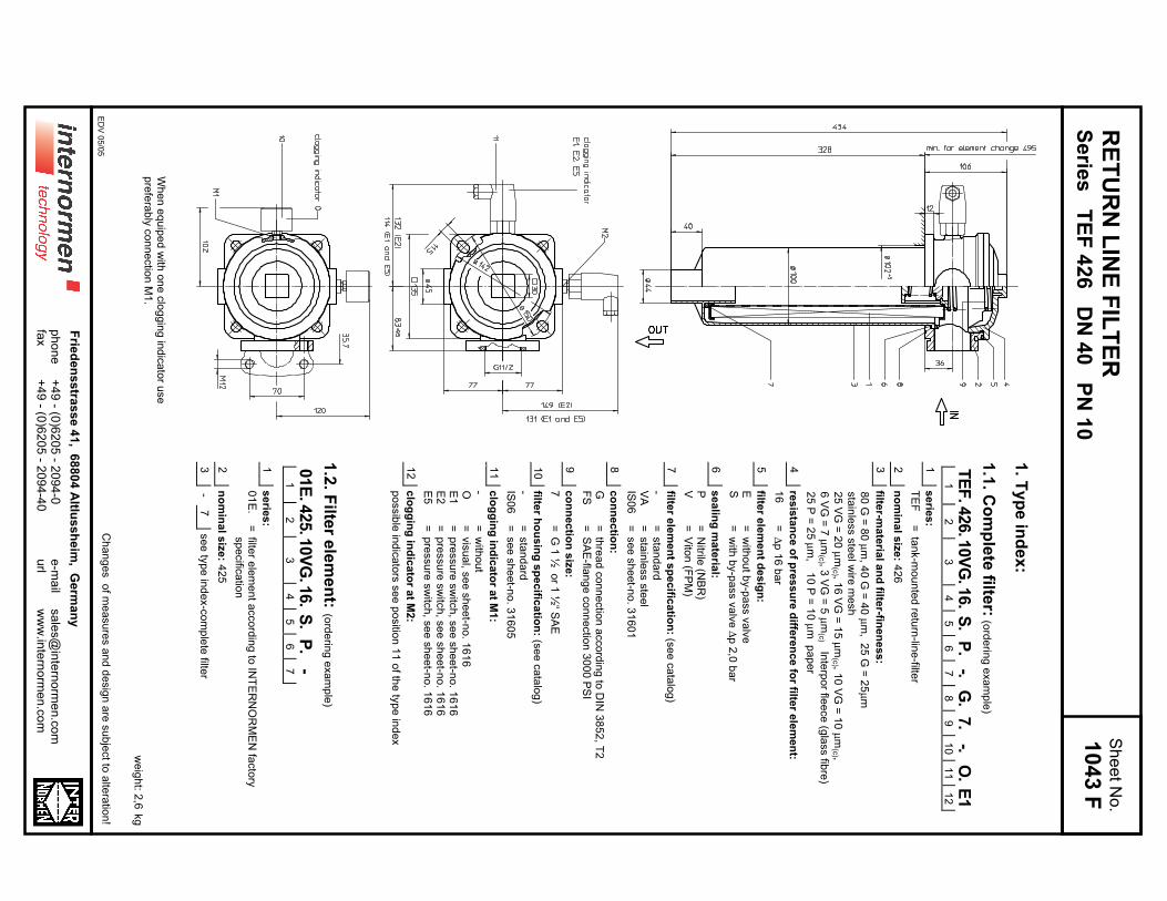
RE
TU
RN
LIN
E F
ILT
ER
Se
ries
TE
F 4
26
DN
40
PN
10
1. T
yp
e in
de
x:
1.1
. Co
mp
lete
filter:
(ord
erin
g e
xa
mp
le)
TE
F.426.1
0V
G.1
6.
S.
P.
-.G
.7.
-.O
.E
11
23
45
67
89
10
11
12
1s
erie
s:
TE
F=
tan
k-m
ou
nte
d re
turn
-line
-filter
2n
om
ina
l siz
e: 4
26
3filte
r-ma
teria
l an
d filte
r-fine
ne
ss
:
80
G =
80
µm
, 40
G =
40
µm
, 25
G =
25
µm
sta
inle
ss s
tee
l wire
me
sh
25
VG
= 2
0 µ
m(c
) , 16
VG
= 1
5 µ
m(c
) , 10
VG
= 1
0 µ
m(c
) ,
6 V
G =
7 µ
m(c
) , 3 V
G =
5 µ
m(c
) Inte
rpo
r flee
ce
(gla
ss fib
re)
25
P =
25
µm
, 1
0 P
= 1
0 µ
m p
ap
er
4re
sis
tan
ce
of p
res
su
re d
iffere
nc
e fo
r filter e
lem
en
t:
16
=∆
p 1
6 b
ar
5filte
r ele
me
nt d
es
ign
:
E=
with
ou
t by-p
ass v
alv
eS
=w
ith b
y-p
ass v
alv
e ∆
p 2
,0 b
ar
6s
ea
ling
ma
teria
l:
P=
Nitrile
(NB
R)
V=
Vito
n (F
PM
)
7filte
r ele
me
nt s
pe
cific
atio
n: (s
ee
ca
talo
g)
-=
sta
nd
ard
VA
=sta
inle
ss s
tee
lIS
06
=se
e s
he
et-n
o. 3
16
01
8c
on
ne
ctio
n:
G=
thre
ad
co
nn
ectio
n a
cco
rdin
g to
DIN
38
52
, T2
FS
=S
AE
-flan
ge
co
nn
ectio
n 3
00
0 P
SI
9c
on
ne
ctio
n s
ize
:
7=
G 1
½ o
r 1 ½
“ SA
E
10
filter h
ou
sin
g s
pe
cific
atio
n: (s
ee
ca
talo
g)
-=
sta
nd
ard
IS0
6=
se
e s
he
et-n
o. 3
16
05
11
clo
gg
ing
ind
ica
tor a
t M1
:
-=
with
ou
tO
=vis
ua
l, se
e s
he
et-n
o. 1
61
6E
1=
pre
ssu
re s
witc
h, s
ee
sh
ee
t-no
. 16
16
E2
=p
ressu
re s
witc
h, s
ee
sh
ee
t-no
. 16
16
E5
=p
ressu
re s
witc
h, s
ee
sh
ee
t-no
. 16
16
12
clo
gg
ing
ind
ica
tor a
t M2
:
po
ssib
le in
dic
ato
rs s
ee
po
sitio
n 1
1 o
f the
typ
e in
de
x
1.2
. Filte
r ele
me
nt:
(ord
erin
g e
xa
mp
le)
01E
.425.1
0V
G.1
6.
S.
P.
-1
23
45
67
1s
erie
s:
01
E.
=filte
r ele
me
nt a
cco
rdin
g to
INT
ER
NO
RM
EN
facto
rysp
ecific
atio
n
2n
om
ina
l siz
e: 4
25
3-
7se
e ty
pe
ind
ex-c
om
ple
te filte
r
we
igh
t: 2,6
kg
Ch
an
ge
s o
f me
asu
res a
nd
de
sig
n a
re s
ub
ject to
alte
ratio
n!
Wh
en
eq
uip
ed
with
on
e c
log
gin
g in
dic
ato
r use
pre
fera
bly
co
nn
ectio
n M
1.
ED
V 0
5/0
5
Sh
ee
t No
.
1043 F
+4
9 - (0
)62
05
- 20
94
-0+
49
- (0)6
20
5 - 2
09
4-4
0p
ho
ne
fax
Frie
de
ns
stra
ss
e 4
1, 6
88
04
Altlu
ss
he
im, G
erm
an
y
e-m
ail
url
sa
les@
inte
rno
rme
n.c
om
ww
w.in
tern
orm
en
.co
m
2. S
pa
re p
arts
:ite
mqty
.desig
natio
ndim
ensio
nartic
le-n
o.
11
filter e
lem
ent
01E
. 425...
-
21
filter h
ead
nom
inal s
ize 4
26
313571
31
filter b
ow
lnom
inal s
ize 4
25
303732
41
scre
w p
lug
M 1
20 x
3313649
51
O-rin
g128 x
3304602 (N
BR
)308140 (F
PM
)
61
O-rin
g98 x
4301914 (N
BR
)304765 (F
PM
)
71
O-rin
g44 x
6302222 (N
BR
)304384 (F
PM
)
81
O-rin
g115 x
3303963 (N
BR
)307762 (F
PM
)
91
sprin
gD
A =
63,5
304983
10
1clo
ggin
g in
dic
ato
r vis
ual
Osee s
heet-n
o. 1
616
11
1clo
ggin
g in
dic
ato
r ele
ctric
al
alte
rnativ
ely
E1, E
2 o
r E5
see s
heet-n
o. 1
616
3. D
es
crip
tion
:R
etu
rn-lin
e filte
rs in
the
TE
F s
erie
s a
re s
uita
ble
for a
wo
rkin
g p
ressu
re u
p to
10
ba
r.P
ressu
re p
ea
ks w
ill be
ab
so
rbe
d b
y a
su
fficie
nt m
arg
in o
f sa
fety
.T
he
TE
F-filte
rs a
re d
irectly
mo
un
ted
to th
e re
se
rvo
ir an
d c
on
ne
cte
d to
the
retu
rn-lin
e.
The filte
r ele
ment c
onsis
ts o
f a s
tar-s
haped, p
leate
d filte
r mate
rial w
hic
h is
supporte
d o
n th
e in
sid
e b
y a
perfo
rate
d c
ore
tub
e a
nd is
bonded to
the e
nd c
aps w
ith a
hig
h-q
uality
adhesiv
e. T
he flo
w is
from
outs
ide to
insid
e. F
ilters
finer th
an 4
0 µ
m s
hould
use th
row
-aw
ay e
lem
ents
made o
f paper o
r Inte
rpor fle
ece (g
lass fib
re). F
ilter e
lem
ents
as fin
e a
s 5
µm
(c) a
re a
vaila
ble
; finer filte
r ele
ments
on
req
ue
st.
INT
ER
NO
RM
EN
-Filte
rs c
an b
e u
sed fo
r petro
leum
-based flu
ids, H
W e
muls
ions, w
ate
r gly
cols
, most s
ynth
etic
fluid
s a
nd lu
bric
atio
nflu
ids. C
on
su
lt facto
ry fo
r sp
ecific
fluid
ap
plic
atio
ns.
INT
ER
NO
RM
EN
-Filte
rs e
lem
ents
are
know
n a
s s
table
ele
ments
whic
h h
ave e
xcelle
nt filtra
tion c
apabilitie
s a
nd a
hig
h d
irt reta
inin
gca
pa
city
, the
refo
re h
avin
g a
lon
g s
erv
ice
life. D
ue
to its
pra
ctic
al d
esig
n, th
e re
turn
-line
filter is
ea
sy to
se
rvic
e.
Wh
en
ch
an
gin
g th
e filte
r ele
me
nt a
de
tach
ab
le c
on
ne
ctio
n b
etw
ee
n th
e filte
r he
ad
an
d th
e filte
r bo
wl p
reve
nts
a flo
w b
ack o
f dirty
oil
into
the
tan
k.
4. T
ec
hn
ica
l da
ta:
tem
pe
ratu
re ra
ng
e:
-10
°C to
+8
0°C
(for a
sh
ort tim
e +
10
0°C
)o
pe
ratin
g m
ed
ium
:m
ine
ral o
il, oth
er m
ed
ia o
n re
qu
est
ma
x. o
pe
ratin
g p
ressu
re:
10
ba
ro
pe
nin
g p
ressu
re b
y-p
ass v
alv
e:
2,0
ba
rco
nn
ectio
n s
yste
m:
thre
ad
co
nn
ectio
n o
r SA
E-fla
ng
e c
on
ne
ctio
n 3
00
0 P
SI
ho
usin
g m
ate
rial:
AL
-ca
stin
g; g
lass fib
re re
info
rce
d p
oly
am
ide
se
alin
g m
ate
rial:
Nitrile
(NB
R) o
r Vito
n (F
PM
), oth
er m
ate
rials
on
req
ue
st
insta
llatio
n p
ositio
n:
ve
rtica
lvo
lum
e ta
nk:
2,5
l
Cla
ssifie
d u
nd
er th
e P
ressu
re E
qu
ipm
en
t Dire
ctiv
e 9
7/2
3/E
C fo
r min
era
l oil (flu
id g
rou
p 2
), Artic
le 3
, Pa
ra. 3
.C
lassifie
d u
nd
er A
TE
X D
irectiv
e 9
4/9
/EC
acco
rdin
g to
sp
ecific
ap
plic
atio
n (s
ee
qu
estio
nn
aire
sh
ee
t-no
. 34
27
9-4
).
5. S
ym
bo
ls:
with
out in
dic
ato
rw
ith b
y-p
ass v
alv
evis
ual O
ele
ctric
al
conta
ct m
aker E
1
ele
ctric
al
conta
ct b
reaker E
5
ele
ctric
al c
onta
ct
maker/b
reaker E
2
6. P
res
su
re d
rop
flow
cu
rve
s:
Pre
cis
e flo
w ra
tes s
ee
‘INT
-Exp
ert-S
yste
m F
ilter’ re
sp
ectiv
ely
∆p
-cu
rve
s ; d
ep
en
din
g
on
filter fin
en
ess a
nd
vis
co
sity
.
7. T
es
t me
tho
ds
:F
ilter e
lem
en
ts a
re te
ste
d a
cco
rdin
g to
the
follo
win
g IS
O s
tan
da
rds:
ISO
29
41
Ve
rifica
tion
of c
olla
pse
/bu
rst re
sis
tan
ce
ISO
29
42
Ve
rifica
tion
of fa
bric
atio
n in
teg
rityIS
O 2
94
3V
erific
atio
n o
f ma
teria
l co
mp
atib
ility w
ith flu
ids
ISO
37
23
Me
tho
d fo
r en
d lo
ad
test
ISO
37
24
Ve
rifica
tion
of flo
w fa
tigu
e c
ha
racte
ristic
sIS
O 3
96
8E
va
lua
tion
of p
ressu
re d
rop
ve
rsu
s flo
w c
ha
racte
ristic
sIS
O 1
68
89
Mu
lti-pa
ss m
eth
od
for e
va
lua
ting
filtratio
n p
erfo
rma
nce
E 1
043 F
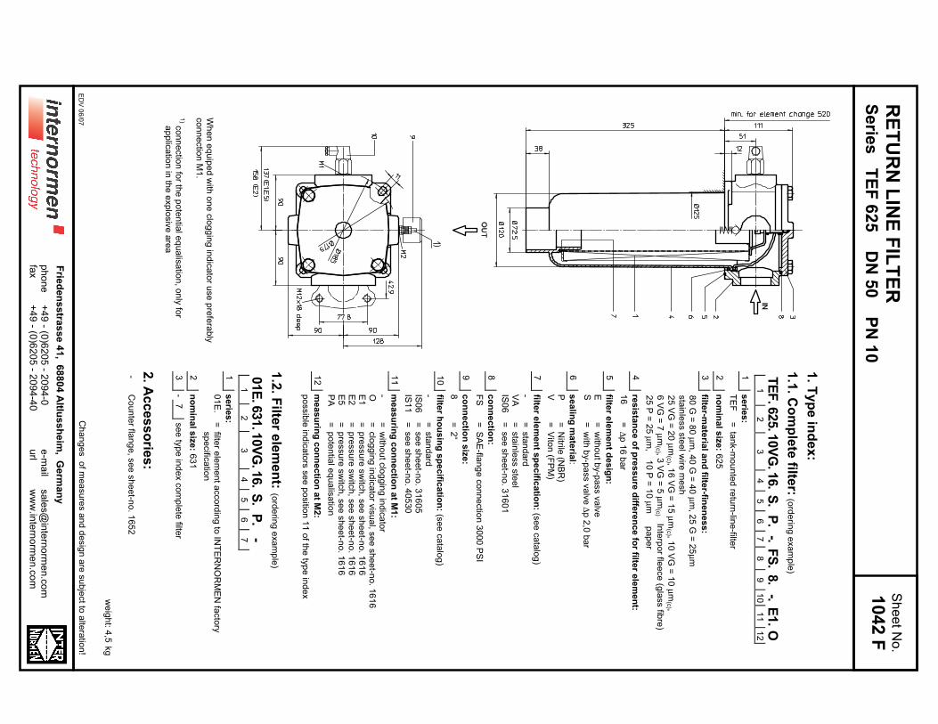
RE
TU
RN
LIN
E F
ILT
ER
Se
ries
TE
F 6
25
DN
50
PN
10
1. T
yp
e in
de
x:
1.1
. Co
mp
lete
filter:
(ord
erin
g e
xa
mp
le)
TE
F.625.1
0V
G.1
6.
S.
P.
-.F
S.
8.
-.E
1.
O1
23
45
67
89
10
11
12
1s
erie
s:
TE
F=
tan
k-m
ou
nte
d re
turn
-line
-filter
2n
om
ina
l siz
e: 6
25
3filte
r-ma
teria
l an
d filte
r-fine
ne
ss
:
80
G =
80
µm
, 40
G =
40
µm
, 25
G =
25
µm
sta
inle
ss s
tee
l wire
me
sh
25
VG
= 2
0 µ
m(c
) , 16
VG
= 1
5 µ
m(c
) , 10
VG
= 1
0 µ
m(c
) ,
6 V
G =
7 µ
m(c
) , 3 V
G =
5 µ
m(c
) Inte
rpo
r flee
ce
(gla
ss fib
re)
25
P =
25
µm
, 1
0 P
= 1
0 µ
m
pa
pe
r
4re
sis
tan
ce
of p
res
su
re d
iffere
nc
e fo
r filter e
lem
en
t:
16
=∆
p 1
6 b
ar
5filte
r ele
me
nt d
es
ign
:
E=
with
ou
t by-p
ass v
alv
eS
=w
ith b
y-p
ass v
alv
e ∆
p 2
,0 b
ar
6s
ea
ling
ma
teria
l:
P=
Nitrile
(NB
R)
V=
Vito
n (F
PM
)
7filte
r ele
me
nt s
pe
cific
atio
n: (s
ee
ca
talo
g)
-=
sta
nd
ard
VA
=sta
inle
ss s
tee
lIS
06
=se
e s
he
et-n
o. 3
16
01
8c
on
ne
ctio
n:
FS
=S
AE
-flan
ge
co
nn
ectio
n 3
00
0 P
SI
9c
on
ne
ctio
n s
ize
:
8=
2“
10
filter h
ou
sin
g s
pe
cific
atio
n: (s
ee
ca
talo
g)
-=
sta
nd
ard
IS0
6=
se
e s
he
et-n
o. 3
16
05
IS1
1=
se
e s
he
et-n
o. 4
05
30
11
me
as
urin
g c
on
ne
ctio
n a
t M1
:
-=
with
ou
tclo
gg
ing
ind
ica
tor
O=
clo
gg
ing
ind
ica
tor v
isu
al, s
ee
sh
ee
t-no
. 16
16
E1
=p
ressu
re s
witc
h, s
ee
sh
ee
t-no
. 16
16
E2
=p
ressu
re s
witc
h, s
ee
sh
ee
t-no
. 16
16
E5
=p
ressu
re s
witc
h, s
ee
sh
ee
t-no
. 16
16
PA
=p
ote
ntia
l eq
ua
lisa
tion
12
me
as
urin
g c
on
ne
ctio
n a
t M2
:
po
ssib
le in
dic
ato
rs s
ee
po
sitio
n 1
1 o
f the
typ
e in
de
x
1.2
. Filte
r ele
me
nt:
(ord
erin
g e
xa
mp
le)
01E
.631.1
0V
G.1
6.
S.
P.
-1
23
45
67
1s
erie
s:
01
E.
=filte
r ele
me
nt a
cco
rdin
g to
INT
ER
NO
RM
EN
facto
rysp
ecific
atio
n
2n
om
ina
l siz
e: 6
31
3-
7se
e ty
pe
ind
ex c
om
ple
te filte
r
2. A
cc
es
so
ries
:-
Co
un
ter fla
ng
e, s
ee
sh
ee
t-no
. 16
52
we
igh
t: 4,5
kg
Ch
an
ge
s o
f me
asu
res a
nd
de
sig
n a
re s
ub
ject to
alte
ratio
n!
Wh
en
eq
uip
ed
with
on
e c
log
gin
g in
dic
ato
r use
pre
fera
bly
co
nn
ectio
n M
1.
1) c
on
ne
ctio
n fo
r the
po
ten
tial e
qu
alis
atio
n, o
nly
for
ap
plic
atio
n in
the
exp
losiv
e a
rea
ED
V 0
6/0
7
Sh
ee
t No
.
1042 F
+4
9 - (0
)62
05
- 20
94
-0+
49
- (0)6
20
5 - 2
09
4-4
0p
ho
ne
fax
Frie
de
ns
stra
ss
e 4
1, 6
88
04
Altlu
ss
he
im, G
erm
an
y
e-m
ail
url
sa
les@
inte
rno
rme
n.c
om
ww
w.in
tern
orm
en
.co
m
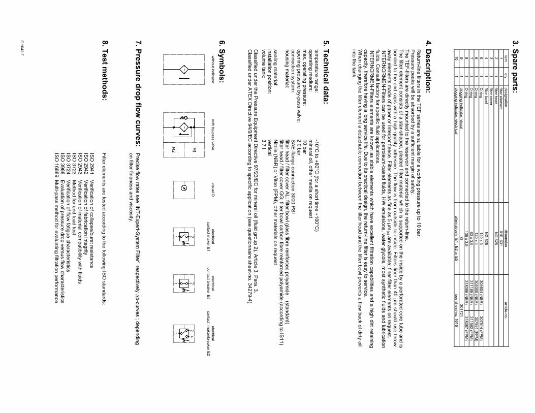
3. S
pa
re p
arts
:ite
mqty
.desig
natio
ndim
ensio
nartic
le-n
o.
11
filter e
lem
ent
01E
. 631
21
filter h
ead
NG
625
31
filter c
over
41
filter b
ow
lN
G 6
25
51
O-rin
g140 x
3304604 (N
BR
)307514 (F
PM
)
61
O-rin
g120 x
4305300 (N
BR
) 3
07991 (F
PM
)
71
O-rin
g63 x
3,5
311189 (N
BR
)311592 (F
PM
)
81
O-rin
g135 x
3,5
318386 (N
BR
)318387 (F
PM
)
91
clo
ggin
g in
dic
ato
r, vis
ual
O301721
10
1clo
ggin
g in
dic
ato
r, ele
ctric
al
alte
rnativ
ely
E1 , E
2 o
r E5
see s
heet-n
o. 1
616
4. D
es
crip
tion
:R
etu
rn-lin
e filte
rs in
the
TE
F s
erie
s a
re s
uita
ble
for a
wo
rkin
g p
ressu
re u
p to
10
ba
r.P
ressu
re p
ea
ks w
ill be
ab
so
rbe
d b
y a
su
fficie
nt m
arg
in o
f sa
fety
.T
he
TE
F-filte
rs a
re d
irectly
mo
un
ted
to th
e re
se
rvo
ir an
d c
on
ne
cte
d to
the
retu
rn-lin
e.
The filte
r ele
ment c
onsis
ts o
f a s
tar-s
haped, p
leate
d filte
r mate
rial w
hic
h is
supporte
d o
n th
e in
sid
e b
y a
perfo
rate
d c
ore
tub
e a
nd is
bonded to
the e
nd c
aps w
ith a
hig
h-q
uality
adhesiv
e. T
he flo
w is
from
outs
ide to
insid
e. F
ilters
finer th
an 4
0 µ
m s
hould
use th
row
-a
wa
y e
lem
en
ts m
ad
e o
f pa
pe
r or In
terp
or fle
ece
. Filte
r ele
me
nts
as fin
e a
s 5
µm
(c) a
re a
va
ilab
le; fin
er filte
r ele
me
nts
on
req
ue
st.
INT
ER
NO
RM
EN
-Filte
rs c
an b
e u
sed fo
r petro
leum
-based flu
ids, H
W e
muls
ions, w
ate
r gly
cols
, most s
ynth
etic
fluid
s a
nd lu
bric
atio
nflu
ids. C
on
su
lt facto
ry fo
r sp
ecific
fluid
ap
plic
atio
ns.
INT
ER
NO
RM
EN
-Filte
rs e
lem
ents
are
know
n a
s s
table
ele
ments
whic
h h
ave e
xcelle
nt filtra
tion c
apabilitie
s a
nd a
hig
h d
irt reta
inin
gca
pa
city
, the
refo
re h
avin
g a
lon
g s
erv
ice
life. D
ue
to its
pra
ctic
al d
esig
n, th
e re
turn
-line
filter is
ea
sy to
se
rvic
e.
Wh
en
ch
an
gin
g th
e filte
r ele
me
nt a
de
tach
ab
le c
on
ne
ctio
n b
etw
ee
n th
e filte
r he
ad
an
d th
e filte
r bo
wl p
reve
nts
a flo
w b
ack o
f dirty
oil
into
the
tan
k.
5. T
ec
hn
ica
l da
ta:
tem
pe
ratu
re ra
ng
e:
-10
°C to
+8
0°C
(for a
sh
ort tim
e +
10
0°C
)o
pe
ratin
g m
ed
ium
:m
ine
ral o
il, oth
er m
ed
ia o
n re
qu
est
ma
x. o
pe
ratin
g p
ressu
re:
10
ba
ro
pe
nin
g p
ressu
re b
y-p
ass v
alv
e:
2,0
ba
rco
nn
ectio
n s
yste
m:
SA
E-fla
ng
e c
on
ne
ctio
n 3
00
0 P
SI
ho
usin
g m
ate
rial:
filter h
ea
d / filte
r co
ve
r AL
; filter b
ow
l gla
ss fib
re re
info
rce
d p
oly
am
ide
(sta
nd
ard
)filte
r he
ad
/ filter c
ove
r GG
; filter b
ow
l ca
rbo
n fib
re re
info
rce
d p
oly
am
ide
(acco
rdin
g to
IS1
1)
se
alin
g m
ate
rial:
Nitrile
(NB
R) o
r Vito
n (F
PM
), oth
er m
ate
rials
on
req
ue
st
insta
llatio
n p
ositio
n:
ve
rtica
lvo
lum
e ta
nk:
3,7
l
Cla
ssifie
d u
nd
er th
e P
ressu
re E
qu
ipm
en
t Dire
ctiv
e 9
7/2
3/E
C fo
r min
era
l oil (flu
id g
rou
p 2
), Artic
le 3
, Pa
ra. 3
.C
lassifie
d u
nd
er A
TE
X D
irectiv
e 9
4/9
/EC
acco
rdin
g to
sp
ecific
ap
plic
atio
n (s
ee
qu
estio
nn
aire
sh
ee
t-no
. 34
27
9-4
).
6. S
ym
bo
ls:
with
out in
dic
ato
rw
ith b
y-p
ass v
alv
evis
ual O
ele
ctric
al
conta
ct m
aker E
1
ele
ctric
al
conta
ct b
reaker E
5
ele
ctric
al
conta
ct m
aker/b
reaker E
2
7. P
res
su
re d
rop
flow
cu
rve
s:
Pre
cis
e flo
w ra
tes s
ee
‘INT
-Exp
ert-S
yste
m F
ilter’ re
sp
ectiv
ely
∆p
-cu
rve
s ; d
ep
en
din
g
on
filter fin
en
ess a
nd
vis
co
sity
.
8. T
es
t me
tho
ds
:F
ilter e
lem
en
ts a
re te
ste
d a
cco
rdin
g to
the
follo
win
g IS
O s
tan
da
rds:
ISO
29
41
Ve
rifica
tion
of c
olla
pse
/bu
rst re
sis
tan
ce
ISO
29
42
Ve
rifica
tion
of fa
bric
atio
n in
teg
rityIS
O 2
94
3V
erific
atio
n o
f ma
teria
l co
mp
atib
ility w
ith flu
ids
ISO
37
23
Me
tho
d fo
r en
d lo
ad
test
ISO
37
24
Ve
rifica
tion
of flo
w fa
tigu
e c
ha
racte
ristic
sIS
O 3
96
8E
va
lua
tion
of p
ressu
re d
rop
ve
rsu
s flo
w c
ha
racte
ristic
sIS
O 1
68
89
Mu
lti-pa
ss m
eth
od
for e
va
lua
ting
filtratio
n p
erfo
rma
nce
E 1
042 F
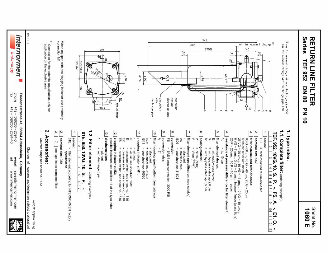
RE
TU
RN
LIN
E F
ILT
ER
Se
ries
TE
F 9
52
DN
80
PN
10
1. T
yp
e in
de
x:
1.1
. Co
mp
lete
filter:
(ord
erin
g e
xa
mp
le)
TE
F.952.1
0V
G.1
0.
S.
P.
-.F
S.
A.
-.E
1.
O.
-1
23
45
67
89
10
11
12
13
1s
erie
s:
TE
F=
tan
k-m
ou
nte
d re
turn
-line
-filter
2n
om
ina
l siz
e: 9
52
3filte
r-ma
teria
l an
d filte
r-fine
ne
ss
:
80
G =
80
µm
, 40
G =
40
µm
, 25
G =
25
µm
sta
inle
ss s
tee
l wire
me
sh
25
VG
= 2
0 µ
m(c
) , 16
VG
= 1
5 µ
m(c
) , 10
VG
= 1
0 µ
m(c
) ,
6 V
G =
7 µ
m(c
) , 3 V
G =
5 µ
m(c
) Inte
rpo
r flee
ce
(gla
ss fib
re)
25
P =
25
µm
, 1
0 P
= 1
0 µ
m
pa
pe
r
4re
sis
tan
ce
of p
res
su
re d
iffere
nc
e fo
r filter e
lem
en
t:
10
=∆
p 1
0 b
ar
5filte
r ele
me
nt d
es
ign
:
E=
with
ou
t by-p
ass v
alv
eS
=w
ith b
y-p
ass v
alv
e ∆
p 2
,0 b
ar
S1
=w
ith b
y-p
ass v
alv
e ∆
p 3
,5 b
ar
6s
ea
ling
ma
teria
l:
P=
Nitrile
(NB
R)
V=
Vito
n (F
PM
)
7filte
r ele
me
nt s
pe
cific
atio
n: (s
ee
ca
talo
g)
-=
sta
nd
ard
VA
=sta
inle
ss s
tee
lIS
06
=se
e s
he
et-n
o. 3
16
01
8c
on
ne
ctio
n:
FS
=S
AE
-flan
ge
co
nn
ectio
n 3
00
0 P
SI
9c
on
ne
ctio
n s
ize
:
A=
3“
10
filter h
ou
sin
g s
pe
cific
atio
n: (s
ee
ca
talo
g)
-=
sta
nd
ard
IS0
6=
se
e s
he
et-n
o. 3
16
05
IS1
1=
se
e s
he
et-n
o. 4
05
30
11
clo
gg
ing
ind
ica
tor a
t M1
:
-=
with
ou
tO
=vis
ua
l, se
e s
he
et-n
o. 1
61
6E
1=
pre
ssu
re s
witc
h, s
ee
sh
ee
t-no
. 16
16
E2
=p
ressu
re s
witc
h, s
ee
sh
ee
t-no
. 16
16
E5
=p
ressu
re s
witc
h, s
ee
sh
ee
t-no
. 16
16
12
clo
gg
ing
ind
ica
tor a
t M2
:
po
ssib
le in
dic
ato
rs s
ee
po
sitio
n 1
1 o
f the
typ
e in
de
x
13
dis
ch
arg
e p
ipe
:
-=
with
ou
t1
=w
ith d
isch
arg
e p
ipe
1.2
. Filte
r ele
me
nt:
(ord
erin
g e
xa
mp
le)
01E
.950.1
0V
G.1
0.
S.
P.
-1
23
45
67
1s
erie
s:
01
E.
=filte
r ele
me
nt a
cco
rdin
g to
INT
ER
NO
RM
EN
facto
rysp
ecific
atio
n
2n
om
ina
l siz
e: 9
50
3-
7se
e ty
pe
ind
ex-c
om
ple
te filte
r
2. A
cc
es
so
ries
:-
Co
un
ter fla
ng
e s
ee
sh
ee
t-no
. 16
52
we
igh
t: ap
pro
x.1
8kg
Ch
an
ge
s o
f me
asu
res a
nd
de
sig
n a
re s
ub
ject to
alte
ratio
n!
Sh
ee
t No
.
1060 E
Wh
en
eq
uip
ed
with
on
e c
log
gin
g in
dic
ato
r use
pre
fera
bly
co
nn
ectio
n M
1.
2) C
on
ne
ctio
n fo
r the
po
ten
tial e
qu
alis
atio
n, o
nly
for
ap
plic
atio
n o
n th
e e
xp
losiv
e a
rea
.
ED
V 1
1/1
0
+4
9 - (0
)62
05
- 20
94
-0+
49
- (0)6
20
5 - 2
09
4-4
0p
ho
ne
fax
Frie
de
ns
stra
ss
e 4
1, 6
88
04
Altlu
ss
he
im, G
erm
an
y
e-m
ail
url
sa
les@
inte
rno
rme
n.c
om
ww
w.in
tern
orm
en
.co
m

3. S
pa
re p
arts
:ite
mqty
.desig
natio
ndim
ensio
nartic
le-n
o.
11
filter e
lem
ent
01.E
950
21
filter h
ead
31
filter c
over
41
filter b
ow
l with
out d
ischarg
e p
ipe
1filte
r bow
l with
dis
charg
e p
ipe
51
O-rin
g195 x
3,5
301831 (N
BR
)306528 (F
PM
)
61
O-rin
g170 x
6304799 (N
BR
)306529 (F
PM
)
71
O-rin
g190 x
5305432 (N
BR
)310283 (F
PM
)
81
O-rin
g78 x
10
305017 (N
BR
)305552 (F
PM
)
91
clo
ggin
g in
dic
ato
r vis
ual
O301721
10
1clo
ggin
g in
dic
ato
r ele
ctric
al
alte
rnativ
ely
E1, E
2 o
r E5
see s
heet-n
o. 1
616
4. D
es
crip
tion
:R
etu
rn-lin
e filte
rs in
the
TE
F s
erie
s a
re s
uita
ble
for a
wo
rkin
g p
ressu
re u
p to
10
ba
r.P
ressu
re p
ea
ks w
ill be
ab
so
rbe
d b
y a
su
fficie
nt m
arg
in o
f sa
fety
.T
he
TE
F-filte
rs a
re d
irectly
mo
un
ted
to th
e re
se
rvo
ir an
d c
on
ne
cte
d to
the
retu
rn-lin
e.
The filte
r ele
ment c
onsis
ts o
f a s
tar-s
haped, p
leate
d filte
r mate
rial w
hic
h is
supporte
d o
n th
e in
sid
e b
y a
perfo
rate
d c
ore
tube a
nd is
bonded to
the e
nd c
aps w
ith a
hig
h-q
uality
adhesiv
e. T
he flo
w is
from
outs
ide to
insid
e. F
ilters
finer th
an 4
0 µ
m s
hould
use th
row
-aw
ay e
lem
ents
made o
f paper o
r Inte
rpor fle
ece (g
lass fib
re). F
ilter e
lem
ents
as fin
e a
s 5
µm
(c) a
re a
vaila
ble
; finer filte
r ele
ments
on
req
ue
st.
INT
ER
NO
RM
EN
-Filte
rs c
an b
e u
sed fo
r petro
leum
-based flu
ids, H
W e
muls
ions, w
ate
r gly
cols
, most s
ynth
etic
fluid
s a
nd lu
bric
atio
nflu
ids. C
on
su
lt facto
ry fo
r sp
ecific
fluid
ap
plic
atio
ns.
INT
ER
NO
RM
EN
-Filte
rs e
lem
ents
are
know
n a
s s
table
ele
ments
whic
h h
ave e
xcelle
nt filtra
tion c
apabilitie
s a
nd a
hig
h d
irt reta
inin
gca
pa
city
, the
refo
re h
avin
g a
lon
g s
erv
ice
life. D
ue
to its
pra
ctic
al d
esig
n, th
e re
turn
-line
filter is
ea
sy to
se
rvic
e.
Wh
en
ch
an
gin
g th
e filte
r ele
me
nt a
de
tach
ab
le c
on
ne
ctio
n b
etw
ee
n th
e filte
r he
ad
an
d th
e filte
r bo
wl p
reve
nts
a flo
w b
ack o
f dirty
oil
into
the
tan
k.
5. T
ec
hn
ica
l da
ta:
tem
pe
ratu
re ra
ng
e:
-10
°C to
+8
0°C
(for a
sh
ort tim
e +
10
0°C
)o
pe
ratin
g m
ed
ium
:m
ine
ral o
il, oth
er m
ed
ia o
n re
qu
est
ma
x. o
pe
ratin
g p
ressu
re:
10
ba
ro
pe
nin
g p
ressu
re b
y-p
ass v
alv
e:
2,0
ba
r, 3,5
ba
rco
nn
ectio
n s
yste
m:
SA
E-fla
ng
e c
on
ne
ctio
n 3
00
0 P
SI
ho
usin
g m
ate
rial:
filter h
ea
d / filte
r co
ve
r AL
, filter b
ow
l gla
ss fib
re re
info
rce
d p
oly
am
ide
(sta
nd
ard
)filte
r he
ad
/ filter c
ove
r GG
, filter b
ow
l ca
rbo
n fib
re re
info
rce
d p
oly
am
ide
(IS1
1)
se
alin
g m
ate
rial:
Nitrile
(NB
R) o
r Vito
n (F
PM
), oth
er m
ate
rials
on
req
ue
st
insta
llatio
n p
ositio
n:
ve
rtica
lvo
lum
e ta
nk:
10
,0 l
Cla
ssifie
d u
nd
er th
e P
ressu
re E
qu
ipm
en
t Dire
ctiv
e 9
7/2
3/E
C fo
r min
era
l oil (flu
id g
rou
p 2
), Artic
le 3
, Pa
ra. 3
.C
lassifie
d u
nd
er A
TE
X D
irectiv
e 9
4/9
/EC
acco
rdin
g to
sp
ecific
ap
plic
atio
n (s
ee
qu
estio
nn
aire
sh
ee
t-no
. 34
27
9-4
).
6. S
ym
bo
ls:
with
out in
dic
ato
rw
ith b
y-p
ass v
alv
evis
ual O
ele
ctric
al
conta
ct m
aker E
1
ele
ctric
al
conta
ct b
reaker E
5
ele
ctric
al
conta
ct m
aker/b
reaker E
2
7. P
res
su
re d
rop
flow
cu
rve
s:
Pre
cis
e flo
w ra
tes s
ee
‘INT
-Exp
ert-S
yste
m F
ilter’ re
sp
ectiv
ely
∆p
-cu
rve
s ; d
ep
en
din
g
on
filter fin
en
ess a
nd
vis
co
sity
.
8. T
es
t me
tho
ds
:F
ilter e
lem
en
ts a
re te
ste
d a
cco
rdin
g to
the
follo
win
g IS
O s
tan
da
rds:
ISO
29
41
Ve
rifica
tion
of c
olla
pse
/bu
rst re
sis
tan
ce
ISO
29
42
Ve
rifica
tion
of fa
bric
atio
n in
teg
rityIS
O 2
94
3V
erific
atio
n o
f ma
teria
l co
mp
atib
ility w
ith flu
ids
ISO
37
23
Me
tho
d fo
r en
d lo
ad
test
ISO
37
24
Ve
rifica
tion
of flo
w fa
tigu
e c
ha
racte
risti
ISO
39
68
Eva
lua
tion
of p
ressu
re d
rop
ve
rsu
s flo
w c
ha
racte
ristic
sIS
O 1
68
89
Mu
lti-pa
ss m
eth
od
for e
va
lua
ting
filtratio
n p
erfo
rma
nce
E 1
060 E
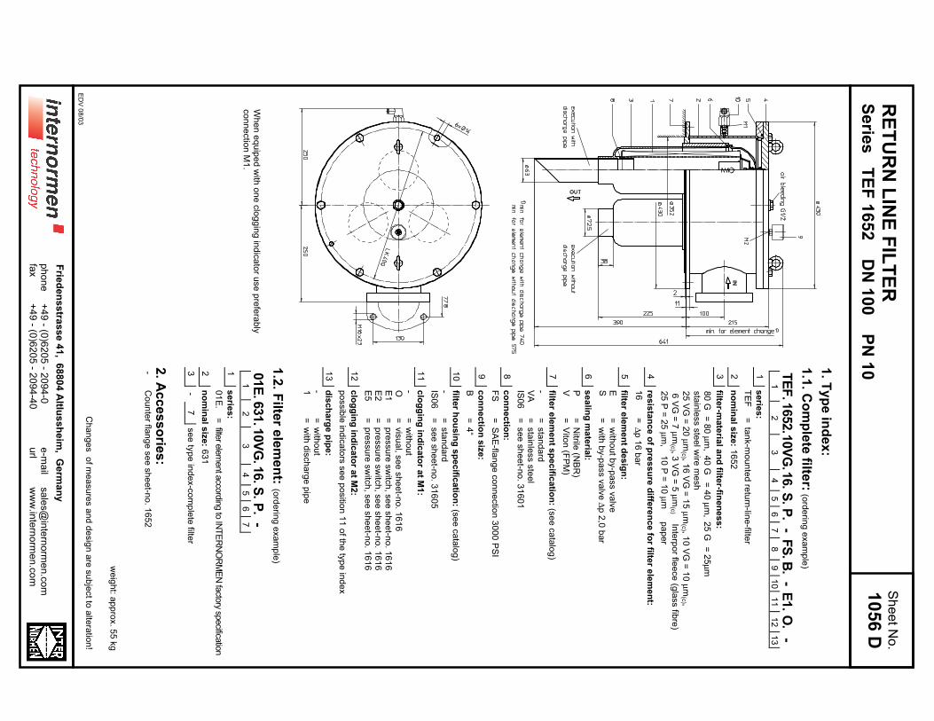
RE
TU
RN
LIN
E F
ILT
ER
Se
ries
TE
F 1
65
2 D
N 1
00
PN
101. T
yp
e in
de
x:
1.1
. Co
mp
lete
filter:
(ord
erin
g e
xa
mp
le)
TE
F.1
652.1
0V
G.1
6.S
.P
.-
FS
.B
.-
E1.
O.
-1
23
45
67
89
10
11
12
13
1s
erie
s:
TE
F=
tan
k-m
ou
nte
d re
turn
-line
-filter
2n
om
ina
l siz
e: 1
65
2
3filte
r-ma
teria
l an
d filte
r-fine
ne
ss
:
80
G=
80
µm
,4
0 G
= 4
0 µ
m,
25
G=
25
µm
sta
inle
ss s
tee
l wire
me
sh
25
VG
= 2
0 µ
m(c
) , 16
VG
= 1
5 µ
m(c
) , 10
VG
= 1
0 µ
m(c
) ,
6 V
G =
7 µ
m(c
) , 3 V
G =
5 µ
m(c
) Inte
rpo
r flee
ce
(gla
ss fib
re)
25
P =
25
µm
, 1
0 P
= 1
0 µ
m
pa
pe
r
4re
sis
tan
ce
of p
res
su
re d
iffere
nc
e fo
r filter e
lem
en
t:
16
=∆
p 1
6 b
ar
5filte
r ele
me
nt d
es
ign
:
E=
with
ou
t by-p
ass v
alv
eS
=w
ith b
y-p
ass v
alv
e ∆
p 2
,0 b
ar
6s
ea
ling
ma
teria
l:
P=
Nitrile
(NB
R)
V=
Vito
n (F
PM
)
7filte
r ele
me
nt s
pe
cific
atio
n: (s
ee
ca
talo
g)
-=
sta
nd
ard
VA
=sta
inle
ss s
tee
lIS
06
=se
e s
he
et-n
o. 3
16
01
8c
on
ne
ctio
n:
FS
=S
AE
-flan
ge
co
nn
ectio
n 3
00
0 P
SI
9c
on
ne
ctio
n s
ize
:
B=
4“
10
filter h
ou
sin
g s
pe
cific
atio
n: (s
ee
ca
talo
g)
-=
sta
nd
ard
IS0
6=
se
e s
he
et-n
o. 3
16
05
11
clo
gg
ing
ind
ica
tor a
t M1
:
-=
with
ou
tO
=vis
ua
l, se
e s
he
et-n
o. 1
61
6E
1=
pre
ssu
re s
witc
h, s
ee
sh
ee
t-no
. 16
16
E2
=p
ressu
re s
witc
h, s
ee
sh
ee
t-no
. 16
16
E5
=p
ressu
re s
witc
h, s
ee
sh
ee
t-no
. 16
16
12
clo
gg
ing
ind
ica
tor a
t M2
:
po
ssib
le in
dic
ato
rs s
ee
po
sitio
n 1
1 o
f the
typ
e in
de
x
13
dis
ch
arg
e p
ipe
:
-=
with
ou
t1
=w
ith d
isch
arg
e p
ipe
1.2
. Filte
r ele
me
nt:
(ord
erin
g e
xa
mp
le)
01E
.631.1
0V
G.1
6.S
.P
.-
12
34
56
7
1s
erie
s:
01
E.
=filte
r ele
ment a
ccord
ing to
INT
ER
NO
RM
EN
facto
ry specifica
tion
2n
om
ina
l siz
e: 6
31
3-
7se
e ty
pe
ind
ex-c
om
ple
te filte
r
2. A
cc
es
so
ries
:-
Co
un
ter fla
ng
e s
ee
sh
ee
t-no
. 16
52
we
igh
t: ap
pro
x. 5
5 k
g
Ch
an
ge
s o
f me
asu
res a
nd
de
sig
n a
re s
ub
ject to
alte
ratio
n!
Sh
ee
t No
.
1056 D
Wh
en
eq
uip
ed
with
on
e c
log
gin
g in
dic
ato
r use
pre
fera
bly
co
nn
ectio
n M
1.
ED
V 0
8/0
3
+4
9 - (0
)62
05
- 20
94
-0+
49
- (0)6
20
5 - 2
09
4-4
0p
ho
ne
fax
Frie
de
ns
stra
ss
e 4
1, 6
88
04
Altlu
ss
he
im, G
erm
an
y
e-m
ail
url
sa
les@
inte
rno
rme
n.c
om
ww
w.in
tern
orm
en
.co
m
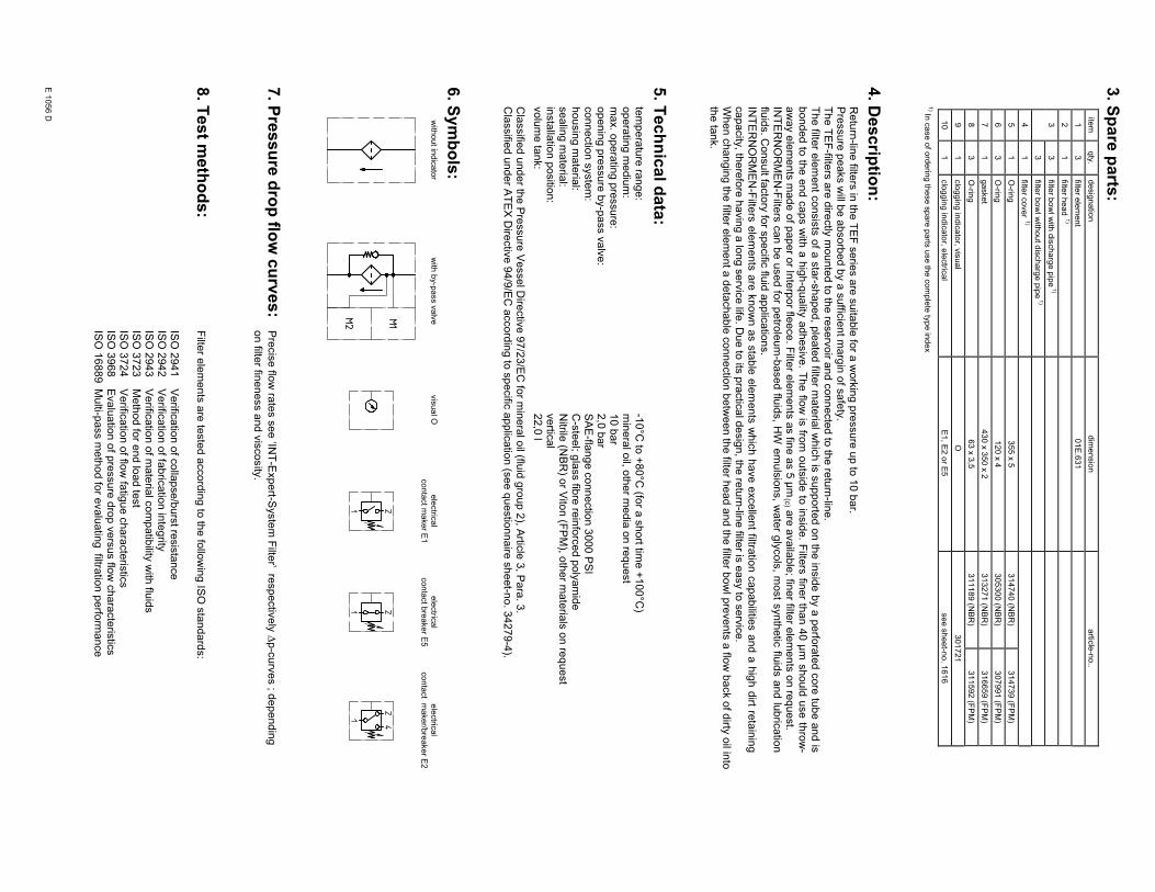
3. S
pa
re p
arts
:ite
mqty
.desig
natio
ndim
ensio
nartic
le-n
o..
13
filter e
lem
ent
01E
.631
21
filter h
ead 1)
33
filter b
ow
l with
dis
charg
e p
ipe
1)
3filte
r bow
l with
out d
ischarg
e p
ipe
1)
41
filter c
over
1)
51
O-rin
g355 x
5314740 (N
BR
)314739 (F
PM
)
63
O-rin
g120 x
4305300 (N
BR
)307991 (F
PM
)
71
gasket
430 x
350 x
2313271 (N
BR
)316659 (F
PM
)
83
O-rin
g63 x
3,5
311189 (N
BR
)311592 (F
PM
)
91
clo
ggin
g in
dic
ato
r, vis
ual
O301721
10
1clo
ggin
g in
dic
ato
r, ele
ctric
al
E1, E
2 o
r E5
see s
heet-n
o. 1
616
1) In
case o
f ord
erin
g th
ese s
pare
parts
use th
e c
om
ple
te ty
pe in
dex
4. D
es
crip
tion
:R
etu
rn-lin
e filte
rs in
the
TE
F s
erie
s a
re s
uita
ble
for a
wo
rkin
g p
ressu
re u
p to
10
ba
r.P
ressu
re p
ea
ks w
ill be
ab
so
rbe
d b
y a
su
fficie
nt m
arg
in o
f sa
fety
.T
he
TE
F-filte
rs a
re d
irectly
mo
un
ted
to th
e re
se
rvo
ir an
d c
on
ne
cte
d to
the
retu
rn-lin
e.
The filte
r ele
ment c
onsis
ts o
f a s
tar-s
haped, p
leate
d filte
r mate
rial w
hic
h is
supporte
d o
n th
e in
sid
e b
y a
perfo
rate
d c
ore
tub
e a
nd is
bonded to
the e
nd c
aps w
ith a
hig
h-q
uality
adhesiv
e. T
he flo
w is
from
outs
ide to
insid
e. F
ilters
finer th
an 4
0 µ
m s
hould
use th
row
-a
wa
y e
lem
en
ts m
ad
e o
f pa
pe
r or In
terp
or fle
ece
. Filte
r ele
me
nts
as fin
e a
s 5
µm
(c) a
re a
va
ilab
le; fin
er filte
r ele
me
nts
on
req
ue
st.
INT
ER
NO
RM
EN
-Filte
rs c
an b
e u
sed fo
r petro
leum
-based flu
ids, H
W e
muls
ions, w
ate
r gly
cols
, most s
ynth
etic
fluid
s a
nd lu
bric
atio
nflu
ids. C
on
su
lt facto
ry fo
r sp
ecific
fluid
ap
plic
atio
ns.
INT
ER
NO
RM
EN
-Filte
rs e
lem
ents
are
know
n a
s s
table
ele
ments
whic
h h
ave e
xcelle
nt filtra
tion c
apabilitie
s a
nd a
hig
h d
irt reta
inin
gca
pa
city
, the
refo
re h
avin
g a
lon
g s
erv
ice
life. D
ue
to its
pra
ctic
al d
esig
n, th
e re
turn
-line
filter is
ea
sy to
se
rvic
e.
Wh
en
ch
an
gin
g th
e filte
r ele
me
nt a
de
tach
ab
le c
on
ne
ctio
n b
etw
ee
n th
e filte
r he
ad
an
d th
e filte
r bo
wl p
reve
nts
a flo
w b
ack o
f dirty
oil in
toth
e ta
nk.
5. T
ec
hn
ica
l da
ta:
tem
pe
ratu
re ra
ng
e:
-10
°C to
+8
0°C
(for a
sh
ort tim
e +
10
0°C
)o
pe
ratin
g m
ed
ium
:m
ine
ral o
il, oth
er m
ed
ia o
n re
qu
est
ma
x. o
pe
ratin
g p
ressu
re:
10
ba
ro
pe
nin
g p
ressu
re b
y-p
ass v
alv
e:
2,0
ba
rco
nn
ectio
n s
yste
m:
SA
E-fla
ng
e c
on
ne
ctio
n 3
00
0 P
SI
ho
usin
g m
ate
rial:
C-s
tee
l; gla
ss fib
re re
info
rce
d p
oly
am
ide
se
alin
g m
ate
rial:
Nitrile
(NB
R) o
r Vito
n (F
PM
), oth
er m
ate
rials
on
req
ue
st
insta
llatio
n p
ositio
n:
ve
rtica
lvo
lum
e ta
nk:
22
,0 l
Cla
ssifie
d u
nd
er th
e P
ressu
re V
esse
l Dire
ctiv
e 9
7/2
3/E
C fo
r min
era
l oil (flu
id g
rou
p 2
), Artic
le 3
, Pa
ra. 3
.C
lassifie
d u
nd
er A
TE
X D
irectiv
e 9
4/9
/EC
acco
rdin
g to
sp
ecific
ap
plic
atio
n (s
ee
qu
estio
nn
aire
sh
ee
t-no
. 34
27
9-4
).
6. S
ym
bo
ls:
with
out in
dic
ato
rw
ith b
y-p
ass v
alv
evis
ual O
ele
ctric
al
conta
ct m
aker E
1
ele
ctric
al
conta
ct b
reaker E
5
ele
ctric
al
conta
ct m
aker/b
reaker E
2
7. P
res
su
re d
rop
flow
cu
rve
s:
P
recis
e flo
w ra
tes s
ee
‘INT
-Exp
ert-S
yste
m F
ilter’ re
sp
ectiv
ely
∆p
-cu
rve
s ; d
ep
en
din
g
on
filter fin
en
ess a
nd
vis
co
sity
.
8. T
es
t me
tho
ds
:F
ilter e
lem
en
ts a
re te
ste
d a
cco
rdin
g to
the
follo
win
g IS
O s
tan
da
rds:
ISO
29
41
Ve
rifica
tion
of c
olla
pse
/bu
rst re
sis
tan
ce
ISO
29
42
Ve
rifica
tion
of fa
bric
atio
n in
teg
rityIS
O 2
94
3V
erific
atio
n o
f ma
teria
l co
mp
atib
ility w
ith flu
ids
ISO
37
23
Me
tho
d fo
r en
d lo
ad
test
ISO
37
24
Ve
rifica
tion
of flo
w fa
tigu
e c
ha
racte
ristic
sIS
O 3
96
8E
va
lua
tion
of p
ressu
re d
rop
ve
rsu
s flo
w c
ha
racte
ristic
sIS
O 1
68
89
Mu
lti-pa
ss m
eth
od
for e
va
lua
ting
filtra
tion
pe
rform
an
ce
E 1
056 D
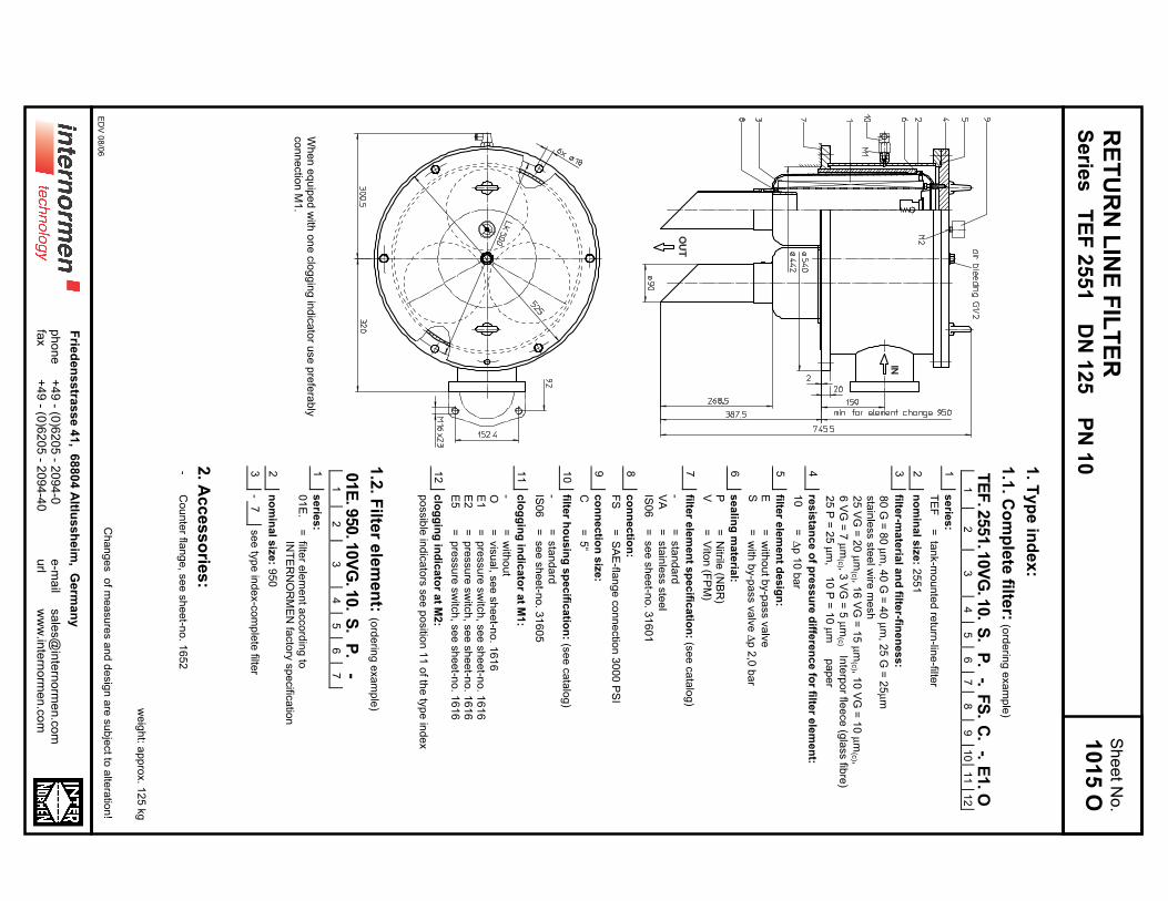
RE
TU
RN
LIN
E F
ILT
ER
Se
ries
TE
F 2
55
1 D
N 1
25
PN
101
. Ty
pe
ind
ex
:
1.1
. Co
mp
lete
filter:
(ord
erin
g e
xa
mp
le)
TE
F.2
551.1
0V
G.1
0.
S.
P.
-.F
S.
C.
-.E
1.O
12
34
56
78
91
01
11
2
1s
erie
s:
TE
F=
tan
k-m
ou
nte
d re
turn
-line
-filter
2n
om
ina
l siz
e: 2
55
1
3filte
r-ma
teria
l an
d filte
r-fine
ne
ss
:
80
G =
80
µm
, 40
G =
40
µm
, 25
G =
25
µm
sta
inle
ss s
tee
l wire
me
sh
25
VG
= 2
0 µ
m(c
) , 16
VG
= 1
5 µ
m(c
) , 10
VG
= 1
0 µ
m(c
) ,
6 V
G =
7 µ
m(c
) , 3 V
G =
5 µ
m(c
) Inte
rpo
r flee
ce
(gla
ss fib
re)
25
P =
25
µm
, 1
0 P
= 1
0 µ
m
pa
pe
r
4re
sis
tan
ce
of p
res
su
re d
iffere
nc
e fo
r filter e
lem
en
t:
10
=∆
p 1
0 b
ar
5filte
r ele
me
nt d
es
ign
:
E=
with
ou
t by-p
ass v
alv
eS
=w
ith b
y-p
ass v
alv
e ∆
p 2
,0 b
ar
6s
ea
ling
ma
teria
l:
P=
Nitrile
(NB
R)
V=
Vito
n (F
PM
)
7filte
r ele
me
nt s
pe
cific
atio
n: (s
ee
ca
talo
g)
-=
sta
nd
ard
VA
=sta
inle
ss s
tee
l
IS0
6=
se
e s
he
et-n
o. 3
16
01
8c
on
ne
ctio
n:
FS
=S
AE
-flan
ge
co
nn
ectio
n 3
00
0 P
SI
9c
on
ne
ctio
n s
ize
:
C=
5“
10
filter h
ou
sin
g s
pe
cific
atio
n: (s
ee
ca
talo
g)
-=
sta
nd
ard
IS0
6=
se
e s
he
et-n
o. 3
16
05
11
clo
gg
ing
ind
ica
tor a
t M1
:
-=
with
ou
tO
=vis
ua
l, se
e s
he
et-n
o. 1
61
6E
1=
pre
ssu
re s
witc
h, s
ee
sh
ee
t-no
. 16
16
E2
=p
ressu
re s
witc
h, s
ee
sh
ee
t-no
. 16
16
E5
=p
ressu
re s
witc
h, s
ee
sh
ee
t-no
. 16
16
12
clo
gg
ing
ind
ica
tor a
t M2
:
po
ssib
le in
dic
ato
rs s
ee
po
sitio
n 1
1 o
f the
typ
e in
de
x
1.2
. Filte
r ele
me
nt:
(ord
erin
g e
xa
mp
le)
01E
.950.1
0V
G.1
0.
S.
P.
-1
23
45
67
1s
erie
s:
01
E.
=filte
r ele
me
nt a
cco
rdin
g to
INT
ER
NO
RM
EN
facto
ry s
pe
cific
atio
n
2n
om
ina
l siz
e: 9
50
3-
7se
e ty
pe
ind
ex-c
om
ple
te filte
r
2. A
cc
es
so
ries
:-
Co
un
ter fla
ng
e, s
ee
sh
ee
t-no
. 16
52
we
igh
t: ap
pro
x. 1
25
kg
Ch
an
ge
s o
f me
asu
res a
nd
de
sig
n a
re s
ub
ject to
alte
ratio
n!
Sh
ee
t No
.
1015 O
Wh
en
eq
uip
ed
with
on
e c
log
gin
g in
dic
ato
r use
pre
fera
bly
co
nn
ectio
n M
1.
ED
V 0
8/0
6
+4
9 - (0
)62
05
- 20
94
-0+
49
- (0)6
20
5 - 2
09
4-4
0p
ho
ne
fax
Frie
de
ns
stra
ss
e 4
1, 6
88
04
Altlu
ss
he
im, G
erm
an
y
e-m
ail
url
sa
les@
inte
rno
rme
n.c
om
ww
w.in
tern
orm
en
.co
m
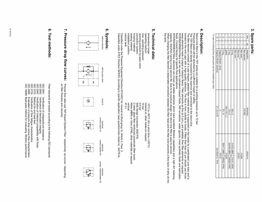
3. S
pa
re p
arts
:ite
mqty
.desig
natio
ndim
ensio
nartic
le-n
o..
13
filter e
lem
ent
01E
.950
21
filter h
ead 1)
313295
33
filter b
ow
l 1)
327461
41
filter c
over
1)
51
O-rin
g455 x
5314742 (N
BR
)314741 (F
PM
)
63
O-rin
g170 x
6304799 (N
BR
)306529 (F
PM
)
71
gasket
540 x
441 x
2313293
83
O-rin
g78 x
10
305017 (N
BR
)305552 (F
PM
)
91
clo
ggin
g in
dic
ato
r, vis
ual
O301721
10
1clo
ggin
g in
dic
ato
r, ele
ctric
al
E1, E
2 o
r E5
see s
heet-n
o. 1
616
1) In
case o
f ord
erin
g th
ese s
pare
parts
use th
e c
om
ple
te ty
pe in
dex
4. D
es
crip
tion
:R
etu
rn-lin
e filte
rs in
the
TE
F s
erie
s a
re s
uita
ble
for a
wo
rkin
g p
ressu
re u
p to
10
ba
r.P
ressu
re p
ea
ks w
ill be
ab
so
rbe
d b
y a
su
fficie
nt m
arg
in o
f sa
fety
.T
he
TE
F-filte
rs a
re d
irectly
mo
un
ted
to th
e re
se
rvo
ir an
d c
on
ne
cte
d to
the
retu
rn-lin
e.
The filte
r ele
ment c
onsis
ts o
f a s
tar-s
haped, p
leate
d filte
r mate
rial w
hic
h is
supporte
d o
n th
e in
sid
e b
y a
perfo
rate
d c
ore
tub
e a
nd is
bonded to
the e
nd c
aps w
ith a
hig
h-q
uality
adhesiv
e. T
he flo
w is
from
outs
ide to
insid
e. F
ilters
finer th
an 4
0 µ
m s
hould
use th
row
-a
wa
y e
lem
en
ts m
ad
e o
f pa
pe
r or In
terp
or fle
ece
. Filte
r ele
me
nts
as fin
e a
s 5
µm
(c) a
re a
va
ilab
le; fin
er filte
r ele
me
nts
on
req
ue
st.
INT
ER
NO
RM
EN
-Filte
rs c
an b
e u
sed fo
r petro
leum
-based flu
ids, H
W e
muls
ions, w
ate
r gly
cols
, most s
ynth
etic
fluid
s a
nd lu
bric
atio
nflu
ids. C
on
su
lt facto
ry fo
r sp
ecific
fluid
ap
plic
atio
ns.
INT
ER
NO
RM
EN
-Filte
rs e
lem
ents
are
know
n a
s s
table
ele
ments
whic
h h
ave e
xcelle
nt filtra
tion c
apabilitie
s a
nd a
hig
h d
irt reta
inin
gca
pa
city
, the
refo
re h
avin
g a
lon
g s
erv
ice
life. D
ue
to its
pra
ctic
al d
esig
n, th
e re
turn
-line
filter is
ea
sy to
se
rvic
e.
Wh
en
ch
an
gin
g th
e filte
r ele
me
nt a
de
tach
ab
le c
on
ne
ctio
n b
etw
ee
n th
e filte
r he
ad
an
d th
e filte
r bo
wl p
reve
nts
a flo
w b
ack o
f dirty
oil in
toth
e ta
nk.
5. T
ec
hn
ica
l da
ta:
tem
pe
ratu
re ra
ng
e:
-10
°C to
+8
0°C
(for a
sh
ort tim
e +
10
0°C
)o
pe
ratin
g m
ed
ium
:m
ine
ral o
il, oth
er m
ed
ia o
n re
qu
est
ma
x. o
pe
ratin
g p
ressu
re:
10
ba
ro
pe
nin
g p
ressu
re b
y-p
ass v
alv
e:
2,0
ba
rco
nn
ectio
n s
yste
m:
SA
E-fla
ng
e c
on
ne
ctio
n 3
00
0 P
SI
ho
usin
g m
ate
rial:
C-s
tee
l. gla
ss fib
er re
info
rce
d p
oly
am
ide
(filter b
ow
l)se
alin
g m
ate
rial:
Nitrile
(NB
R) o
r Vito
n (F
PM
), oth
er m
ate
rials
on
req
ue
st
insta
llatio
n p
ositio
n:
ve
rtica
lvo
lum
e ta
nk:
47
,0 l
Cla
ssifie
d u
nd
er th
e P
ressu
re E
qu
ipm
en
t Dire
ctiv
e 9
7/2
3/E
C fo
r min
era
l oil (flu
id g
rou
p 2
), Artic
le 3
, Pa
ra. 3
.C
lassifie
d u
nd
er A
TE
X D
irectiv
e 9
4/9
/EC
acco
rdin
g to
sp
ecific
ap
plic
atio
n (s
ee
qu
estio
nn
aire
sh
ee
t-no
. 34
27
9-4
).
6. S
ym
bo
ls:
with
out in
dic
ato
rw
ith b
y-p
ass v
alv
evis
ual O
ele
ctric
al
conta
ct m
aker E
1
ele
ctric
al
conta
ct b
reaker E
5
ele
ctric
al
conta
ct m
aker/b
reaker E
2
7. P
res
su
re d
rop
flow
cu
rve
s:
Pre
cis
e flo
w ra
tes s
ee
‘INT
-Exp
ert-S
yste
m F
ilter’ re
sp
ectiv
ely
∆p
-cu
rve
s ; d
ep
en
din
g
on
filter fin
en
ess a
nd
vis
co
sity
.
8. T
es
t me
tho
ds
:F
ilter e
lem
en
ts a
re te
ste
d a
cco
rdin
g to
the
follo
win
g IS
O s
tan
da
rds:
ISO
29
41
Ve
rifica
tion
of c
olla
pse
/bu
rst re
sis
tan
ce
ISO
29
42
Ve
rifica
tion
of fa
bric
atio
n in
teg
rityIS
O 2
94
3V
erific
atio
n o
f ma
teria
l co
mp
atib
ility w
ith flu
ids
ISO
37
23
Me
tho
d fo
r en
d lo
ad
test
ISO
37
24
Ve
rifica
tion
of flo
w fa
tigu
e c
ha
racte
ristic
sIS
O 3
96
8E
va
lua
tion
of p
ressu
re d
rop
ve
rsu
s flo
w c
ha
racte
ristic
sIS
O 1
68
89
Mu
lti-pa
ss m
eth
od
for e
va
lua
ting
filtra
tion
pe
rform
an
ce
E 1
015 O
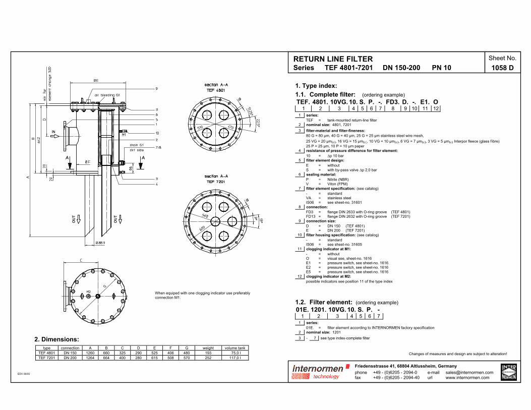
RETURN LINE FILTERSeries TEF 4801-7201 DN 150-200 PN 10
Sheet No.
1058 D
1. Type index:
1.1. Complete filter: (ordering example)
TEF. 4801. 10VG. 10. S. P. -. FD3. D. -. E1. O1 2 3 4 5 6 7 8 9 10 11 12
1 series:
TEF = tank-mounted return-line filter
2 nominal size: 4801, 7201
3 filter-material and filter-fineness:
80 G = 80 µm, 40 G = 40 µm, 25 G = 25 µm stainless steel wire mesh,
25 VG = 20 µm(c), 16 VG = 15 µm(c), 10 VG = 10 µm(c), 6 VG = 7 µm(c), 3 VG = 5 µm(c) Interpor fleece (glass f ibre)
25 P = 25 µm, 10 P = 10 µm paper
4 resistance of pressure difference for filter element:
10 = ∆p 10 bar
5 filter element design:
E = without
S = with by-pass valve ∆p 2,0 bar
6 sealing material:
P = Nitrile (NBR)
V = Viton (FPM)
7 filter element specification: (see catalog)
- = standard
VA = stainless steel
IS06 = see sheet-no. 31601
8 connection:
FD3 = flange DIN 2633 with O-ring groove (TEF 4801)
FD13 = flange DIN 2632 with O-ring groove (TEF 7201)
9 connection size:
D = DN 150 (TEF 4801)
E = DN 200 (TEF 7201)
10 filter housing specification: (see catalog)
- = standard
IS06 = see sheet-no. 31605
11 clogging indicator at M1:
- = without
O = visual see, sheet-no. 1616
E1 = pressure switch, see sheet-no. 1616
E2 = pressure switch, see sheet-no. 1616
E5 = pressure switch, see sheet-no. 1616
12 clogging indicator at M2:
possible indicators see position 11 of the type index
1.2. Filter element: (ordering example)
01E. 1201. 10VG. 10. S. P. -1 2 3 4 5 6 7
1 series:
01E. = filter element according to INTERNORMEN factory specification
2 nominal size: 1201
3 - 7 see type index-complete filter
Changes of measures and design are subject to alteration!
When equiped with one clogging indicator use preferably
connection M1.
2. Dimensions:
type connection A B C D E F G weight volume tank
TEF 4801 DN 150 1260 660 325 290 525 406 480 193 75,0 l
TEF 7201 DN 200 1264 664 400 280 615 508 570 252 117,0 l
EDV 08/05 phonefax
+49 - (0)6205 - 2094-0+49 - (0)6205 - 2094-40
Friedensstrasse 41, 68804 Altlussheim, Germany
e-mailurl
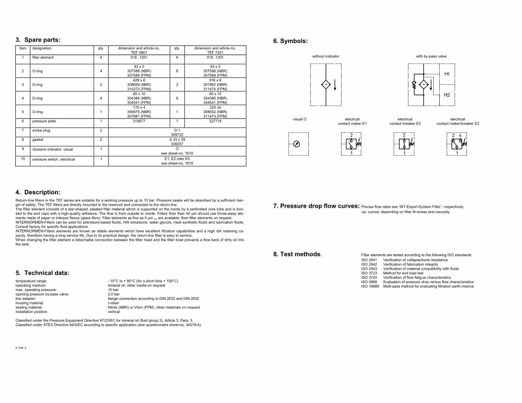
3. Spare parts:
item designation qty. dimension and article-no. qty. dimension and article-no.
TEF 4801 TEF 7201
1 filter element 4 01E. 1201 6 01E. 1201
93 x 5 93 x 5
2 O-ring 4 307588 (NBR) 6 307588 (NBR)
307589 (FPM) 307589 (FPM)
429 x 6 516 x 6
3 O-ring 2 308659 (NBR) 2 301962 (NBR)
310273 (FPM) 311474 (FPM)
85 x 10 85 x 10
4 O-ring 4 304386 (NBR) 6 304386 (NBR)
304541 (FPM) 304541 (FPM)
170 x 4 225 x5
5 O-ring 1 306875 (NBR) 1 308652 (NBR)
307987 (FPM) 311473 (FPM)
6 pressure plate 1 319677 1 327718
7 screw plug 2 G 1
309732
8 gasket 2 A 33 x 39
308257
9 clogging indicator, visual 1 O
see sheet-no. 1616
10 pressure switch, electrical 1 E1, E2 oder E5
see sheet-no. 1616
4. Description:
Return-line filters in the TEF series are suitable for a working pressure up to 10 bar. Pressure peaks will be absorbed by a sufficient mar-
gin of safety. The TEF-filters are directly mounted to the reservoir and connected to the return-line.
The filter element consists of a star-shaped, pleated filter material which is supported on the inside by a perforated core tube and is bon-
ded to the end caps with a high-quality adhesive. The flow is from outside to inside. Filters finer than 40 µm should use throw-away ele-
ments made of paper or Interpor fleece (glass fibre). Filter elements as fine as 5 µm (c) are available; finer filter elements on request.
INTERNORMEN-Filters can be used for petroleum-based fluids, HW emulsions, water glycols, most synthetic fluids and lubrication fluids.
Consult factory for specific fluid applications.
INTERNORMEN-Filters elements are known as stable elements which have excellent filtration capabilities and a high dirt retaining ca-
pacity, therefore having a long service life. Due to its practical design, the return-line filter is easy to service.
When changing the filter element a detachable connection between the filter head and the filter bowl prevents a flow back of dirty oil into
the tank.
5. Technical data:
temperature range: - 10°C to + 80°C (for a short time + 100°C)
operating medium: mineral oil, other media on request
max. operating pressure: 10 bar
opening pressure by-pass valve: 2,0 bar
line adapter: flange connection according to DIN 2633 and DIN 2632
housing material: c-steel
sealing material: Nitrile (NBR) or Viton (FPM), other materials o n request
installation position: vertical
Classified under the Pressure Equipment Directive 97/23/EC for mineral oil (fluid group 2), Article 3, Para. 3.
Classified under ATEX Directive 94/9/EC according to specific application (see questionnaire sheet-no. 34279-4).
E 1058 D
6. Symbols:
without indicator with by-pass valve
visual O electrical
contact maker E1
electrical
contact breaker E5
electrical
contact maker/breaker E2
7. Pressure drop flow curves: Precise flow rates see ‘INT-Expert-System Filter’, respectively
∆p- curves; depending on filter fin eness and viscosity.
8. Test methods: Filter elements are tested according to the following ISO standards:
ISO 2941 Verification of collapse/burst resistance
ISO 2942 Verification of fabrication integrity
ISO 2943 Verification of material compatibility with fluids
ISO 3723 Method for end load test
ISO 3724 Verification of flow fatigue characteristics
ISO 3968 Evaluation of pressure drop versus flow charact eristics
ISO 16889 Multi-pass method for evaluating filtration perfo rmance
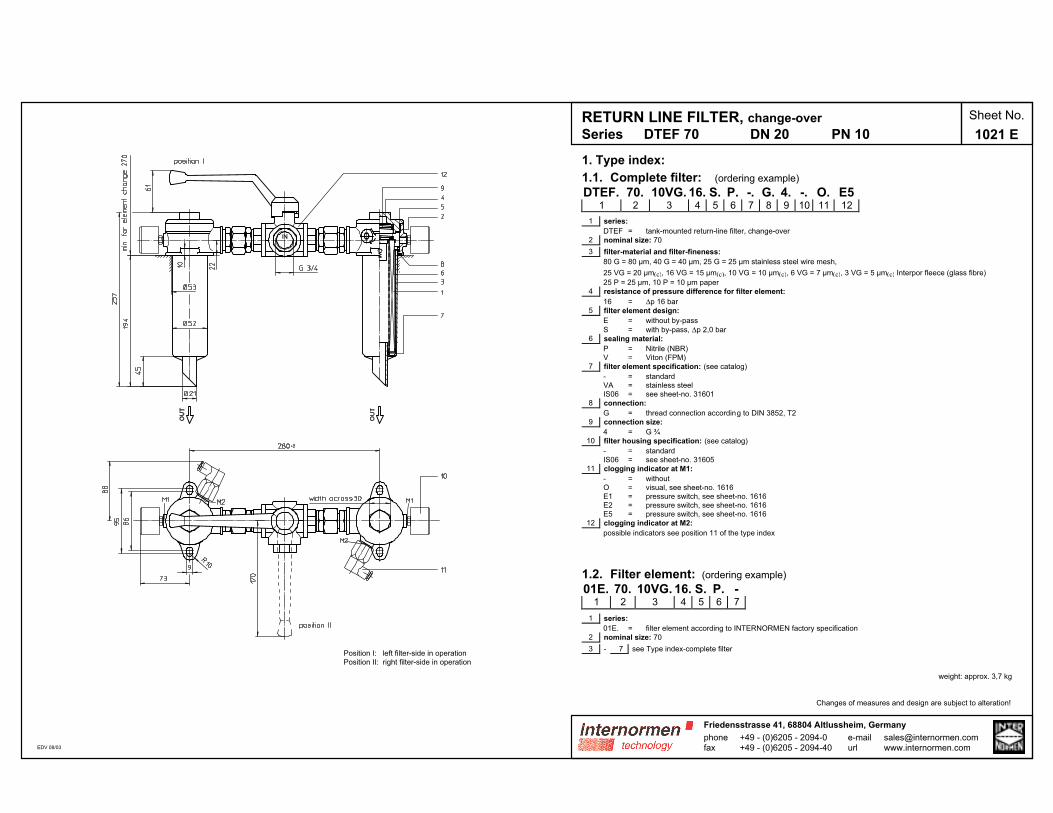
1. Type index:
1.1. Complete filter: (ordering example)
DTEF. 70. 10VG. 16. S. P. -. G. 4. -. O. E51 2 3 4 5 6 7 8 9 10 11 12
1 series:
DTEF = tank-mounted return-line filter, change-over
2 nominal size: 70
3 filter-material and filter-fineness:
80 G = 80 µm, 40 G = 40 µm, 25 G = 25 µm stainless steel wire mesh,
25 VG = 20 µm(c), 16 VG = 15 µm(c), 10 VG = 10 µm(c), 6 VG = 7 µm(c), 3 VG = 5 µm(c) Interpor fleece (glass fibre)
25 P = 25 µm, 10 P = 10 µm paper
4 resistance of pressure difference for filter element:
16 = ∆p 16 bar
5 filter element design:
E = without by-pass
S = with by-pass, ∆p 2,0 bar
6 sealing material:
P = Nitrile (NBR)
V = Viton (FPM)
7 filter element specification: (see catalog)
- = standard
VA = stainless steel
IS06 = see sheet-no. 31601
8 connection:
G = thread connection according to DIN 3852, T2
9 connection size:
4 = G ¾
10 filter housing specification: (see catalog)
- = standard
IS06 = see sheet-no. 31605
11 clogging indicator at M1:
- = without
O = visual, see sheet-no. 1616
E1 = pressure switch, see sheet-no. 1616
E2 = pressure switch, see sheet-no. 1616
E5 = pressure switch, see sheet-no. 1616
12 clogging indicator at M2:
possible indicators see position 11 of the type index
1.2. Filter element: (ordering example)
01E. 70. 10VG. 16. S. P. -1 2 3 4 5 6 7
1 series:
01E. = filter element according to INTERNORMEN factory specification
2 nominal size: 70
3 - 7 see Type index-complete filter
weight: approx. 3,7 kg
Changes of measures and design are subject to alteration!
RETURN LINE FILTER, change-over
Series DTEF 70 DN 20 PN 10
Sheet No.
1021 E
phonefax
+49 - (0)6205 - 2094-0+49 - (0)6205 - 2094-40
Friedensstrasse 41, 68804 Altlussheim, Germany
e-mailurl
Position I: left filter-side in operation
Position II: right filter-side in operation
EDV 08/03
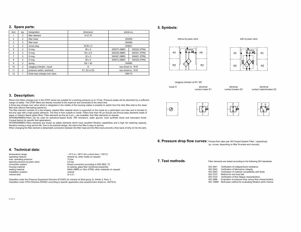
2. Spare parts:
item qty. designation dimension article-no.
1 2 filter element 01.E 70 -
2 2 filter head 305459
3 2 filter bowl 304595
4 2 screw plug M 60 x 2 303621
5 2 O-ring 56 x 3 305072 (NBR) 305322 (FPM)
6 2 O-ring 50 x 2,5 305239 (NBR) 305321 (FPM)
7 2 O-ring 22 x 3 304387 (NBR) 304931 (FPM)
8 4 O-ring 56 x 3 305072 (NBR) 305322 (FPM)
9 2 spring DA = 40 304982
10 2 clogging indicator, visual O see sheet-no. 1616
11 2 pressure switch, electrical E1, E2 or E5 see sheet-no. 1616
12 1 three-way-change-over valve 308115
3. Description:
Return-line filters change-over in the DTEF series are suitable for a working pressure up to 10 bar. Pressure peaks will be absorbed by a sufficient
margin of safety. The DTEF-filters are directly mounted to the reservoir and connected to the return-line.
A three-way-change-over valve which is integrated in the middle of the housing makes it possible to switch from the dirty filter-side to the clean
filter-side without interrupting operat ion.
The filter element consists of a star-shaped, pleated filter material which is supported on the inside by a perforated core tube and is bonded to
the end caps with a high-quality adhesive. The flow is from outside to inside. Filters finer than 40 µm should use throuw-away elements made of
paper or Interpor fleece (glass fibre). Filter elements as fine as 5 µm (c) are available; finer filter elements on request.
INTERNORMEN-Filters can be used for petroleum-based fluids, HW emulsions, water glycols, most synthetic fluids and lubrication fluids.
Consult factory for specific fluid applications.
INTERNORMEN-Filters elements are known as stable elements which have excellent filtration capabilities and a high dirt retaining capacity,
therefore having a long service life. Due to its practical design, the return-line filter is easy to service.
When changing the filter element a detachable connection between the filter head and the filter bowl prevents a flow back of dirty oil into the tank.
4. Technical data:
temperature range: - 10°C to + 80°C (for a short time + 100°C)
operating medium: mineral oil, other media on request
max. operating pressure: 10 bar
opening pressure by-pass valve: 2,0 bar
connection system: thread connection according to DIN 3852, T2
housing material: Al-casting; glass fiber reinforced polyamide
sealing material: Nitrile (NBR) or Viton (FPM), other materials on request
installation position: vertical
volume tank: 2x 0,3 l
Classified under the Pressure Equipment Directive 97/23/EC for mineral oil (fluid group 2), Article 3, Para. 3.
Classified under ATEX Directive 94/9/EC according to specific application (see questionnaire sheet-no. 34279-4).
E 1021 E
5. Symbols:
without by-pass valve with by-pass valve
clogging indicator at M1, M2
visual O electrical
contact maker E1
electrical
contact breaker E5
electrical
contact maker/breaker E2
6. Pressure drop flow curves: Precise flow rates see ‘INT-Expert-System Filter’, respectively
∆p- curves; depending on filter fin eness and viscosity.
7. Test methods: Filter elements are tested according to the following ISO standards:
ISO 2941 Verification of collapse/burst resistance
ISO 2942 Verification of fabricat ion integrity
ISO 2943 Verification of material compatibility with fluids
ISO 3723 Method for end load test
ISO 3724 Verification of flow fatigue characteristics
ISO 3968 Evaluation of pressure drop versus flow charact eristics
ISO 16889 Multi-pass method for evaluating filtration perfo rmance
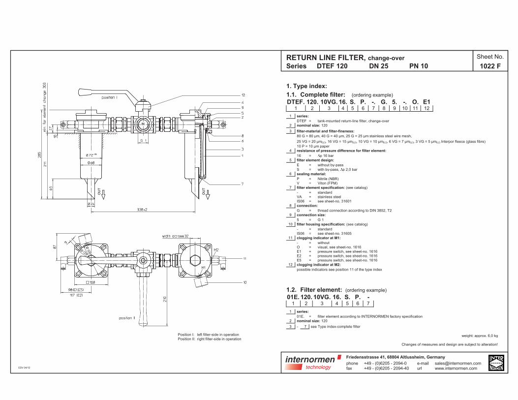
1. Type index:
1.1. Complete filter: (ordering example)
DTEF. 120. 10VG. 16. S. P. -. G. 5. -. O. E11 2 3 4 5 6 7 8 9 10 11 12
1 series:
DTEF = tank-mounted return-line filter, change-over
2 nominal size: 120
3 filter-material and filter-fineness:
80 G = 80 µm, 40 G = 40 µm, 25 G = 25 µm stainless steel wire mesh,
25 VG = 20 µm(c), 16 VG = 15 µm(c), 10 VG = 10 µm(c), 6 VG = 7 µm(c), 3 VG = 5 µm(c) Interpor fleece (glass fibre)
10 P = 10 µm paper
4 resistance of pressure difference for filter element:
16 = p 16 bar
5 filter element design:
E = without by-pass
S = with by-pass, p 2,0 bar
6 sealing material:
P = Nitrile (NBR)
V = Viton (FPM)
7 filter element specification: (see catalog)
- = standard
VA = stainless steel
IS06 = see sheet-no. 31601
8 connection:
G = thread connection according to DIN 3852, T2
9 connection size:
5 = G 1
10 filter housing specification: (see catalog)
- = standard
IS06 = see sheet-no. 31605
11 clogging indicator at M1:
- = without
O = visual, see sheet-no. 1616
E1 = pressure switch, see sheet-no. 1616
E2 = pressure switch, see sheet-no. 1616
E5 = pressure switch, see sheet-no. 1616
12 clogging indicator at M2:
possible indicators see position 11 of the type index
1.2. Filter element: (ordering example)
01E. 120. 10VG. 16. S. P. -1 2 3 4 5 6 7
1 series:
01E. = filter element according to INTERNORMEN factory specification
2 nominal size: 120
3 - 7 see Type index-complete filter
weight: approx. 6,0 kg
Changes of measures and design are subject to alteration!
RETURN LINE FILTER, change-over
Series DTEF 120 DN 25 PN 10
Sheet No.
1022 F
Position I: left filter-side in operation
Position II: right filter-side in operation
EDV 04/12
phonefax
+49 - (0)6205 - 2094-0+49 - (0)6205 - 2094-40
Friedensstrasse 41, 68804 Altlussheim, Germany
e-mailurl
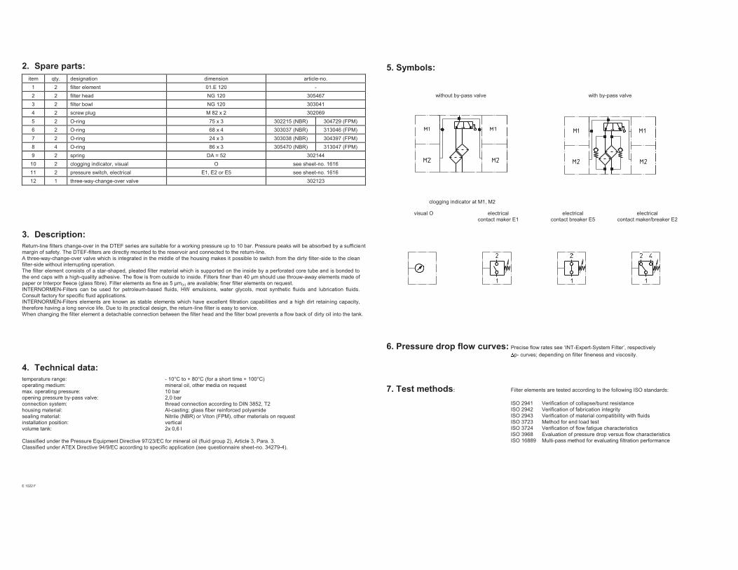
2. Spare parts:
item qty. designation dimension article-no.
1 2 filter element 01.E 120 -
2 2 filter head NG 120 305467
3 2 filter bowl NG 120 303041
4 2 screw plug M 82 x 2 302069
5 2 O-ring 75 x 3 302215 (NBR) 304729 (FPM)
6 2 O-ring 68 x 4 303037 (NBR) 313046 (FPM)
7 2 O-ring 24 x 3 303038 (NBR) 304397 (FPM)
8 4 O-ring 86 x 3 305470 (NBR) 313047 (FPM)
9 2 spring DA = 52 302144
10 2 clogging indicator, visual O see sheet-no. 1616
11 2 pressure switch, electrical E1, E2 or E5 see sheet-no. 1616
12 1 three-way-change-over valve 302123
3. Description:
Return-line filters change-over in the DTEF series are suitable for a working pressure up to 10 bar. Pressure peaks will be absorbed by a sufficient
margin of safety. The DTEF-filters are directly mounted to the reservoir and connected to the return-line.
A three-way-change-over valve which is integrated in the middle of the housing makes it possible to switch from the dirty filter-side to the clean
filter-side without interrupting operation.
The filter element consists of a star-shaped, pleated filter material which is supported on the inside by a perforated core tube and is bonded to
the end caps with a high-quality adhesive. The flow is from outside to inside. Filters finer than 40 µm should use throuw-away elements made of
paper or Interpor fleece (glass fibre). Filter elements as fine as 5 µm(c) are available; finer filter elements on request.
INTERNORMEN-Filters can be used for petroleum-based fluids, HW emulsions, water glycols, most synthetic fluids and lubrication fluids.
Consult factory for specific fluid applications.
INTERNORMEN-Filters elements are known as stable elements which have excellent filtration capabilities and a high dirt retaining capacity,
therefore having a long service life. Due to its practical design, the return-line filter is easy to service.
When changing the filter element a detachable connection between the filter head and the filter bowl prevents a flow back of dirty oil into the tank.
4. Technical data:
temperature range: - 10°C to + 80°C (for a short time + 100°C)
operating medium: mineral oil, other media on request
max. operating pressure: 10 bar
opening pressure by-pass valve: 2,0 bar
connection system: thread connection according to DIN 3852, T2
housing material: Al-casting; glass fiber reinforced polyamide
sealing material: Nitrile (NBR) or Viton (FPM), other materials on request
installation position: vertical
volume tank: 2x 0,6 l
Classified under the Pressure Equipment Directive 97/23/EC for mineral oil (fluid group 2), Article 3, Para. 3.
Classified under ATEX Directive 94/9/EC according to specific application (see questionnaire sheet-no. 34279-4).
E 1022 F
5. Symbols:
without by-pass valve with by-pass valve
clogging indicator at M1, M2
visual O electrical
contact maker E1
electrical
contact breaker E5
electrical
contact maker/breaker E2
6. Pressure drop flow curves: Precise flow rates see ‘INT-Expert-System Filter’, respectively
p- curves; depending on filter fineness and viscosity.
7. Test methods: Filter elements are tested according to the following ISO standards:
ISO 2941 Verification of collapse/burst resistance
ISO 2942 Verification of fabrication integrity
ISO 2943 Verification of material compatibility with fluids
ISO 3723 Method for end load test
ISO 3724 Verification of flow fatigue characteristics
ISO 3968 Evaluation of pressure drop versus flow characteristics
ISO 16889 Multi-pass method for evaluating filtration performance
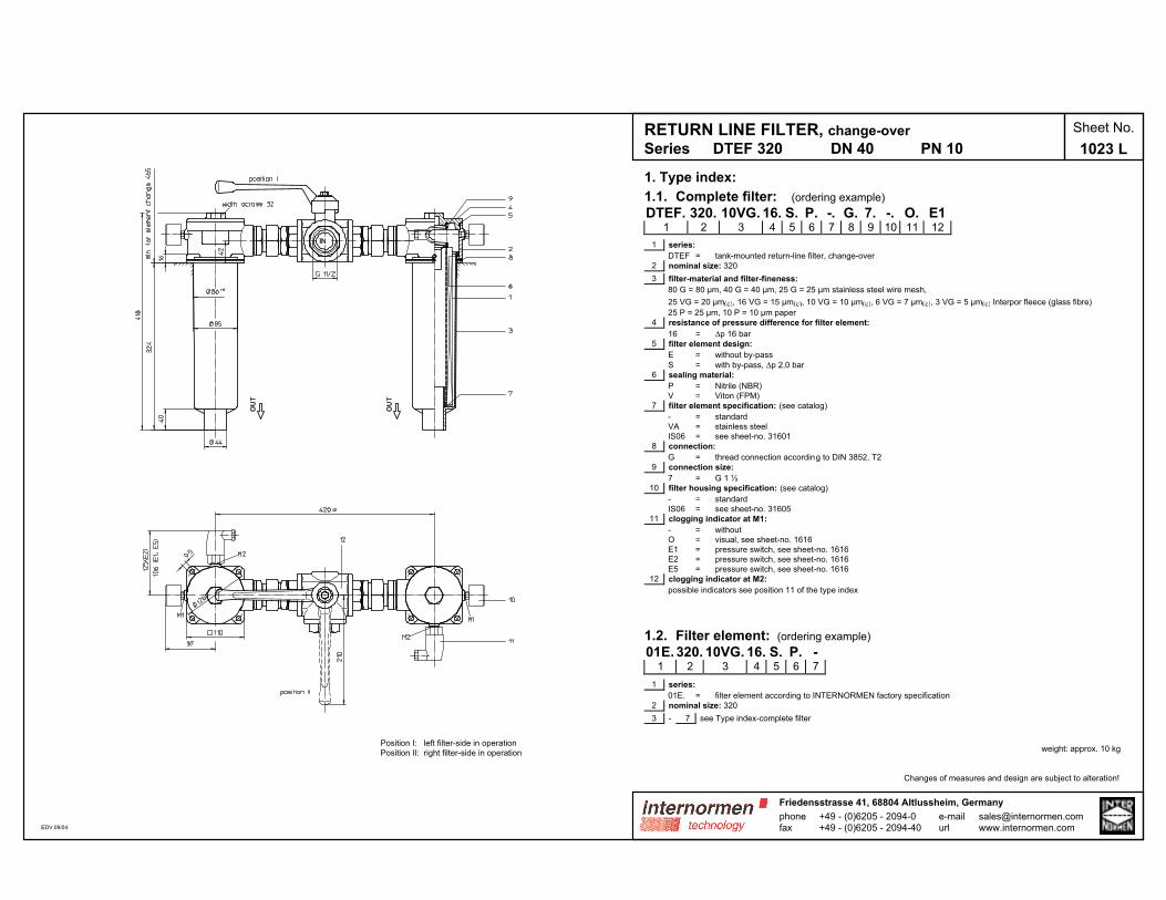
1. Type index:
1.1. Complete filter: (ordering example)
DTEF. 320. 10VG. 16. S. P. -. G. 7. -. O. E11 2 3 4 5 6 7 8 9 10 11 12
1 series:
DTEF = tank-mounted return-line filter, change-over
2 nominal size: 320
3 filter-material and filter-fineness:
80 G = 80 µm, 40 G = 40 µm, 25 G = 25 µm stainless steel wire mesh,
25 VG = 20 µm(c), 16 VG = 15 µm(c), 10 VG = 10 µm(c), 6 VG = 7 µm(c), 3 VG = 5 µm(c) Interpor fleece (glass fibre)
25 P = 25 µm, 10 P = 10 µm paper
4 resistance of pressure difference for filter element:
16 = ∆p 16 bar
5 filter element design:
E = without by-pass
S = with by-pass, ∆p 2,0 bar
6 sealing material:
P = Nitrile (NBR)
V = Viton (FPM)
7 filter element specification: (see catalog)
- = standard
VA = stainless steel
IS06 = see sheet-no. 31601
8 connection:
G = thread connection according to DIN 3852, T2
9 connection size:
7 = G 1 ½
10 filter housing specification: (see catalog)
- = standard
IS06 = see sheet-no. 31605
11 clogging indicator at M1:
- = without
O = visual, see sheet-no. 1616
E1 = pressure switch, see sheet-no. 1616
E2 = pressure switch, see sheet-no. 1616
E5 = pressure switch, see sheet-no. 1616
12 clogging indicator at M2:
possible indicators see position 11 of the type index
1.2. Filter element: (ordering example)
01E. 320. 10VG. 16. S. P. -1 2 3 4 5 6 7
1 series:
01E. = filter element according to INTERNORMEN factory specification
2 nominal size: 320
3 - 7 see Type index-complete filter
weight: approx. 10 kg
Changes of measures and design are subject to alteration!
RETURN LINE FILTER, change-over
Series DTEF 320 DN 40 PN 10
Sheet No.
1023 L
phonefax
+49 - (0)6205 - 2094-0+49 - (0)6205 - 2094-40
Friedensstrasse 41, 68804 Altlussheim, Germany
e-mailurl
Position I: left filter-side in operation
Position II: right filter-side in operation
EDV 09/04
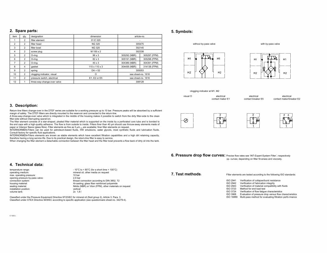
2. Spare parts:
item qty. designation dimension article-no.
1 2 filter element 01.E 320 -
2 2 filter head NG 320 305475
3 2 filter bowl NG 320 302145
4 2 screw plug M 100 x 2 302338
5 2 O-ring 96 x 3 305292 (NBR) 305297 (FPM)
6 2 O-ring 82 x 3 305191 (NBR) 305298 (FPM)
7 2 O-ring 40 x 3 304389 (NBR) 304391 (FPM)
8 4 gasket 110 x 110 x 3 304456 (NBR) 314138 (FPM)
9 2 spring DA = 52 305053
10 2 clogging indicator, visual O see sheet-no. 1616
11 2 pressure switch, electrical E1, E2 or E5 see sheet-no. 1616
12 1 three-way-change-over valve 308128
3. Description:
Return-line filters change-over in the DTEF series are suitable for a working pressure up to 10 bar. Pressure peaks will be absorbed by a sufficient
margin of safety. The DTEF-filters are directly mounted to the reservoir and connected to the return-line.
A three-way-change-over valve which is integrated in the middle of the housing makes it possible to switch from the dirty filter-side to the clean
filter-side without interrupting operat ion.
The filter element consists of a star-shaped, pleated filter material which is supported on the inside by a perforated core tube and is bonded to
the end caps with a high-quality adhesive. The flow is from outside to inside. Filters finer than 40 µm should use throuw-away elements made of
paper or Interpor fleece (glass fibre). Filter elements as fine as 5 µm (c) are available; finer filter elements on request.
INTERNORMEN-Filters can be used for petroleum-based fluids, HW emulsions, water glycols, most synthetic fluids and lubrication fluids.
Consult factory for specific fluid applications.
INTERNORMEN-Filters elements are known as stable elements which have excellent filtration capabilities and a high dirt retaining capacity,
therefore having a long service life. Due to its practical design, the return-line filter is easy to service.
When changing the filter element a detachable connection between the filter head and the filter bowl prevents a flow back of dirty oil into the tank.
4. Technical data:
temperature range: - 10°C to + 80°C (for a short time + 100°C)
operating medium: mineral oil, other media on request
max. operating pressure: 10 bar
opening pressure by-pass valve: 2,0 bar
connection system: thread connection according to DIN 3852, T2
housing material: Al-casting; glass fiber reinforced polyamide
sealing material: Nitrile (NBR) or Viton (FPM), other materials on request
installation position: vertical
volume tank: 2x 1,8 l
Classified under the Pressure Equipment Directive 97/23/EC for mineral oil (fluid group 2), Article 3, Para. 3.
Classified under ATEX Directive 94/9/EC according to specific application (see questionnaire sheet-no. 34279-4).
E 1023 L
5. Symbols:
without by-pass valve with by-pass valve
clogging indicator at M1, M2
visual O electrical
contact maker E1
electrical
contact breaker E5
electrical
contact maker/breaker E2
6. Pressure drop flow curves: Precise flow rates see ‘INT-Expert-System Filter’, respectively
∆p- curves; depending on filter fin eness and viscosity.
7. Test methods: Filter elements are tested according to the following ISO standards:
ISO 2941 Verification of collapse/burst resistance
ISO 2942 Verification of fabrication integrity
ISO 2943 Verification of material compatibility with fluids
ISO 3723 Method for end load test
ISO 3724 Verification of flow fatigue characteristics
ISO 3968 Evaluation of pressure drop versus flow charact eristics
ISO 16889 Multi-pass method for evaluating filtration perfo rmance
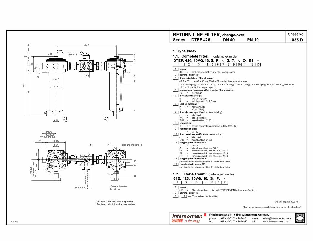
RETURN LINE FILTER, change-over
Series DTEF 426 DN 40 PN 10
Sheet No.
1035 D
Position I: left filter-side in operation
Position II: right filter-side in operation
EDV 08/03
1. Type index:
1.1. Complete filter: (ordering example)
DTEF. 426. 10VG. 16. S. P. -. G. 7. -. O. E1. -1 2 3 4 5 6 7 8 9 10 11 12 13
1 series:
DTEF = tank-mounted return-line filter, change-over
2 nominal size: 426
3 filter-material and filter-fineness:
80 G = 80 µm, 40 G = 40 µm, 25 G = 25 µm stainless steel wire mesh,
25 VG = 20 µm(c), 16 VG = 15 µm(c), 10 VG = 10 µm(c), 6 VG = 7 µm(c), 3 VG = 5 µm(c) Interpor fleece (glass fibre)
25 P = 25 µm, 10 P = 10 µm paper
4 resistance of pressure difference for filter element:
16 = ∆p 16 bar
5 filter element design:
E = without by-pass
S = with by-pass, ∆p 2,0 bar
6 sealing material:
P = Nitrile (NBR)
V = Viton (FPM)
7 filter element specification: (see catalog)
- = standard
VA = stainless steel
IS06 = see sheet-no. 31601
8 connection:
G = thread connection according to DIN 3852, T2
9 connection size:
7 = G 1 ½
10 filter housing specification: (see catalog)
- = standard
IS06 = see sheet-no. 31605
11 clogging indicator at M1:
- = without
O = visual, see sheet-no. 1616
E1 = pressure switch, see sheet-no. 1616
E2 = pressure switch, see sheet-no. 1616
E5 = pressure switch, see sheet-no. 1616
12 clogging indicator at M2:
possible indicators see position 11 of the type index
13 clogging indicator at M3:
possible indicators see position 11 of the type index
1.2. Filter element: (ordering example)
01E. 425. 10VG. 16. S. P. -1 2 3 4 5 6 7
1 series:
01E. = filter element according to INTERNORMEN factory specification
2 nominal size: 425
3 - 7 see Type index-complete filter
weight: approx. 12,5 kg
Changes of measures and design are subject to alteration!
phonefax
+49 - (0)6205 - 2094-0+49 - (0)6205 - 2094-40
Friedensstrasse 41, 68804 Altlussheim, Germany
e-mailurl
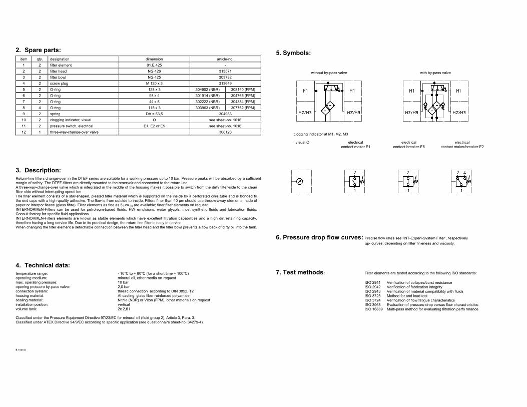
2. Spare parts:
item qty. designation dimension article-no.
1 2 filter element 01.E 425 -
2 2 filter head NG 426 313571
3 2 filter bowl NG 425 303732
4 2 screw plug M 120 x 3 313649
5 2 O-ring 128 x 3 304602 (NBR) 308140 (FPM)
6 2 O-ring 98 x 4 301914 (NBR) 304765 (FPM)
7 2 O-ring 44 x 6 302222 (NBR) 304384 (FPM)
8 4 O-ring 115 x 3 303963 (NBR) 307762 (FPM)
9 2 spring DA = 63,5 304983
10 2 clogging indicator, visual O see sheet-no. 1616
11 2 pressure switch, electrical E1, E2 or E5 see sheet-no. 1616
12 1 three-way-change-over valve 308128
3. Description:
Return-line filters change-over in the DTEF series are suitable for a working pressure up to 10 bar. Pressure peaks will be absorbed by a sufficient
margin of safety. The DTEF-filters are directly mounted to the reservoir and connected to the return-line.
A three-way-change-over valve which is integrated in the middle of the housing makes it possible to switch from the dirty filter-side to the clean
filter-side without interrupting operat ion.
The filter element consists of a star-shaped, pleated filter material which is supported on the inside by a perforated core tube and is bonded to
the end caps with a high-quality adhesive. The flow is from outside to inside. Filters finer than 40 µm should use throuw-away elements made of
paper or Interpor fleece (glass fibre). Filter elements as fine as 5 µm (c) are available; finer filter elements on request.
INTERNORMEN-Filters can be used for petroleum-based fluids, HW emulsions, water glycols, most synthetic fluids and lubrication fluids.
Consult factory for specific fluid applications.
INTERNORMEN-Filters elements are known as stable elements which have excellent filtration capabilities and a high dirt retaining capacity,
therefore having a long service life. Due to its practical design, the return-line filter is easy to service.
When changing the filter element a detachable connection between the filter head and the filter bowl prevents a flow back of dirty oil into the tank.
4. Technical data:
temperature range: - 10°C to + 80°C (for a short time + 100°C)
operating medium: mineral oil, other media on request
max. operating pressure: 10 bar
opening pressure by-pass valve: 2,0 bar
connection system: thread connection according to DIN 3852, T2
housing material: Al-casting; glass fiber reinforced polyamide
sealing material: Nitrile (NBR) or Viton (FPM), other materials on request
installation position: vertical
volume tank: 2x 2,6 l
Classified under the Pressure Equipment Directive 97/23/EC for mineral oil (fluid group 2), Article 3, Para. 3.
Classified under ATEX Directive 94/9/EC according to specific application (see questionnaire sheet-no. 34279-4).
E 1035 D
5. Symbols:
without by-pass valve with by-pass valve
clogging indicator at M1, M2, M3
visual O electrical
contact maker E1
electrical
contact breaker E5
electrical
contact maker/breaker E2
6. Pressure drop flow curves: Precise flow rates see ‘INT-Expert-System Filter’, respectively
∆p- curves; depending on filter fin eness and viscosity.
7. Test methods: Filter elements are tested according to the following ISO standards:
ISO 2941 Verification of collapse/burst resistance
ISO 2942 Verification of fabrication integrity
ISO 2943 Verification of material compatibility with fluids
ISO 3723 Method for end load test
ISO 3724 Verification of flow fatigue characteristics
ISO 3968 Evaluation of pressure drop versus flow charact eristics
ISO 16889 Multi-pass method for evaluating filtration perfo rmance
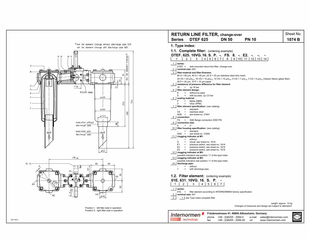
RETURN LINE FILTER, change-over
Series DTEF 625 DN 50 PN 10
Sheet No.
1074 B
1. Type index:
1.1. Complete filter: (ordering example)
DTEF. 625. 10VG. 16. S. P. -. FS. 8. -. E2. -. -. -1 2 3 4 5 6 7 8 9 10 11 12 13 14
1 series:
DTEF = tank-mounted return-line filter, change-over
2 nominal size: 625
3 filter-material and filter-fineness:
80 G = 80 µm, 40 G = 40 µm, 25 G = 25 µm stainless steel wire mesh,
25 VG = 20 µm(c), 16 VG = 15 µm(c), 10 VG = 10 µm(c), 6 VG = 7 µm(c), 3 VG = 5 µm(c) Interpor fleece (glass fiber)
25 P = 25 µm, 10 P = 10 µm paper
4 resistance of pressure difference for filter element:
16 = ∆p 16 bar
5 filter element design:
E = without by-pass
S = with by-pass, ∆p 2,0 bar
6 sealing material:
P = Nitrile (NBR)
V = Viton (FPM)
7 filter element specification: (see catalog)
- = standard
VA = stainless steel
IS06 = see sheet-no. 31601
8 connection:
FS = SAE-flange connection 3000 PSI
9 connection size:
8 = 2“
10 filter housing specification: (see catalog)
- = standard
IS06 = see sheet-no. 31605
11 clogging indicator at M1:
- = without
O = visual, see sheet-no. 1616
E1 = pressure switch, see sheet-no. 1616
E2 = pressure switch, see sheet-no. 1616
E5 = pressure switch, see sheet-no. 1616
12 clogging indicator at M2:
possible indicators see position 11 of the type index
13 clogging indicator at M3:
possible indicators see position 11 of the type index
14 discharge pipe:
- = without
1 = with discharge pipe
1.2. Filter element: (ordering example)
01E. 631. 10VG. 16. S. P. -1 2 3 4 5 6 7
1 series:
01E. = filter element according to INTERNORMEN factory specification
2 nominal size: 631
3 - 7 see Type index-complete filter
weight: approx. 15 kg
Changes of measures and design are subject to alteration!
phonefax
+49 - (0)6205 - 2094-0+49 - (0)6205 - 2094-40
Friedensstrasse 41, 68804 Altlussheim, Germany
e-mailurl
Position I: left filter-side in operation
Position II: right filter-side in operation
EDV 08/03

2. Spare parts:
item qty. designation dimension article-no.
1 2 filter element 01.E 631 -
2 2 filter head TEF 625 316414
3 2 filter cover 32571-4 311662
4 2 filter bowl without discharge pipe 316416
2 filter bowl with discharge pipe
5 2 O-ring 140 x 3 304604 (NBR) 307514 (FPM)
6 2 O-ring 120 x 4 305300 (NBR) 307991 (FPM)
7 2 O-ring 63 x 3,5 311189 (NBR) 311592 (FPM)
8 2 O-ring 135 x 3,5 318386 (NBR) 318387 (FPM)
9 1 O-ring 56,75 x 3,53 306035 (NBR) 310264 (FPM)
10 1 O-ring 75 x 3 302215 (NBR) 304729 (FPM)
11 2 O-ring 18 x 3 304359 (NBR) 304399 (FPM)
12 2 screw plug G ¼ 305003
13 1 pressure switch, electrical E1, E2 or E5 see sheet-no. 1616
14 1 clogging indicator, visual O see sheet-no. 1616
3. Description:
Return-line filters change-over in the DTEF series are suitable for a working pressure up to 10 bar. Pressure peaks will be absorbed by a sufficient
margin of safety. The DTEF-filters are directly mounted to the reservoir and connected to the return-line.
A rotary slide valve which is integrated in the middle of the housing makes it possible to switch from the dirty filter-side to the clean filter-side
without interrupting operat ion.
The filter element consists of a star-shaped, pleated filter material which is supported on the inside by a perforated core tube and is bonded to
the end caps with a high-quality adhesive. The flow is from outside to inside. Filters finer than 40 µm should use throuw-away elements made of
paper or Interpor fleece (glass fibre). Filter elements as fine as 5 µm (c) are available; finer filter elements on request.
INTERNORMEN-Filters can be used for petroleum-based fluids, HW emulsions, water glycols, most synthetic fluids and lubrication fluids.
Consult factory for specific fluid applications.
INTERNORMEN-Filters elements are known as stable elements which have excellent filtration capabilities and a high dirt retaining capacity,
therefore having a long service life. Due to its practical design, the return-line filter is easy to service.
When changing the filter element a detachable connection between the filter head and the filter bowl prevents a flow back of dirty oil into the tank.
4. Technical data:
temperature range: - 10°C to + 80°C (for a short time + 100°C)
operating medium: mineral oil, other media on request
max. operating pressure: 10 bar
opening pressure by-pass valve: 2,0 bar
connection system: SAE-flange connection 3000 PSI
housing material: Al-casting; glass fiber reinforced polyamide
sealing material: Nitrile (NBR) or Viton (FPM), other materials on request
installation position: vertical
volume tank: 2x 3,9 l
Classified under the Pressure Equipment Directive 97/23/EC for mineral oil (fluid group 2), Article 3, Para. 3.
Classified under ATEX Directive 94/9/EC according to specific application (see questionnaire sheet-no. 34279-4).
E 1074 B
5. Symbols:
without by-pass valve with by-pass valve
clogging indicator at M1, M2, M3
visual O electrical
contact maker E1
electrical
contact breaker E5
electrical
contact maker/breaker E2
6. Pressure drop flow curves: Precise flow rates see ‘INT-Expert-System Filter’, respectively
∆p- curves; depending on filter fin eness and viscosity.
7. Test methods: Filter elements are tested according to the following ISO standards:
ISO 2941 Verification of collapse/burst resistance
ISO 2942 Verification of fabrication integrity
ISO 2943 Verification of material compatibility with fluids
ISO 3723 Method for end load test
ISO 3724 Verification of flow fatigue characteristics
ISO 3968 Evaluation of pressure drop versus flow charact eristics
ISO 16889 Multi-pass method for evaluating filtration perfo rmance
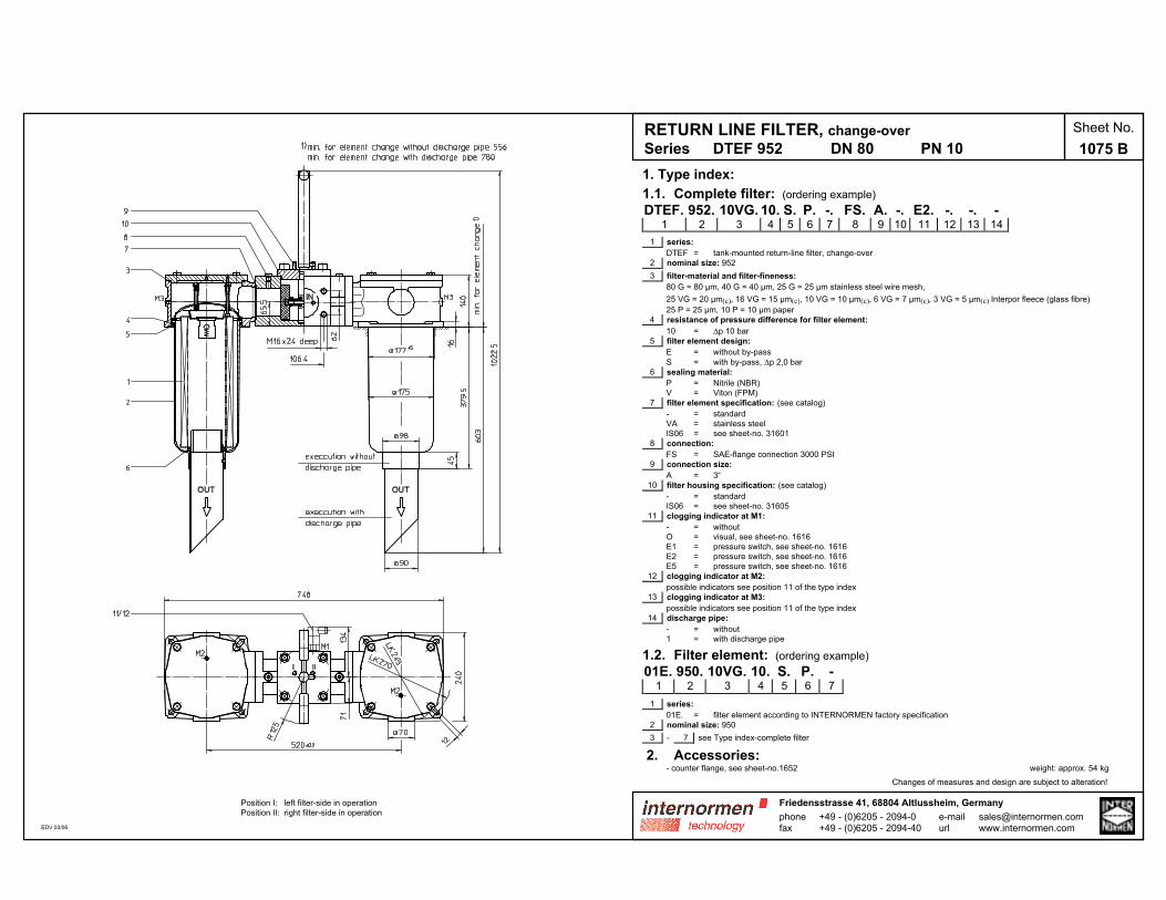
1. Type index:
1.1. Complete filter: (ordering example)
DTEF. 952. 10VG. 10. S. P. -. FS. A. -. E2. -. -. -1 2 3 4 5 6 7 8 9 10 11 12 13 14
1 series:
DTEF = tank-mounted return-line filter, change-over
2 nominal size: 952
3 filter-material and filter-fineness:
80 G = 80 µm, 40 G = 40 µm, 25 G = 25 µm stainless steel wire mesh,
25 VG = 20 µm(c), 16 VG = 15 µm(c), 10 VG = 10 µm(c), 6 VG = 7 µm(c), 3 VG = 5 µm(c) Interpor fleece (glass fibre)
25 P = 25 µm, 10 P = 10 µm paper
4 resistance of pressure difference for filter element:
10 = ∆p 10 bar
5 filter element design:
E = without by-pass
S = with by-pass, ∆p 2,0 bar
6 sealing material:
P = Nitrile (NBR)
V = Viton (FPM)
7 filter element specification: (see catalog)
- = standard
VA = stainless steel
IS06 = see sheet-no. 31601
8 connection:
FS = SAE-flange connection 3000 PSI
9 connection size:
A = 3“
10 filter housing specification: (see catalog)
- = standard
IS06 = see sheet-no. 31605
11 clogging indicator at M1:
- = without
O = visual, see sheet-no. 1616
E1 = pressure switch, see sheet-no. 1616
E2 = pressure switch, see sheet-no. 1616
E5 = pressure switch, see sheet-no. 1616
12 clogging indicator at M2:
possible indicators see position 11 of the type index
13 clogging indicator at M3:
possible indicators see position 11 of the type index
14 discharge pipe:
- = without
1 = with discharge pipe
1.2. Filter element: (ordering example)
01E. 950. 10VG. 10. S. P. -1 2 3 4 5 6 7
1 series:
01E. = filter element according to INTERNORMEN factory specification
2 nominal size: 950
3 - 7 see Type index-complete filter
2. Accessories:- counter flange, see sheet-no.1652 weight: approx. 54 kg
Changes of measures and design are subject to alteration!
RETURN LINE FILTER, change-over
Series DTEF 952 DN 80 PN 10
Sheet No.
1075 B
phonefax
+49 - (0)6205 - 2094-0+49 - (0)6205 - 2094-40
Friedensstrasse 41, 68804 Altlussheim, Germany
e-mailurl
Position I: left filter-side in operation
Position II: right filter-side in operation
EDV 03/06
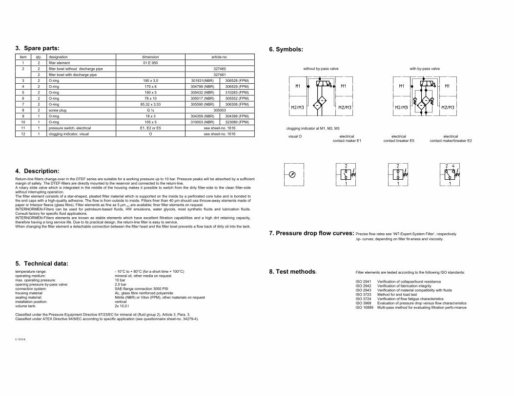
3. Spare parts:
item qty. designation dimension article-no.
1 2 filter element 01.E 950
2 2 filter bowl without discharge pipe 327460
2 filter bowl with discharge pipe 327461
3 2 O-ring 195 x 3,5 301831(NBR) 306528 (FPM)
4 2 O-ring 170 x 6 304799 (NBR) 306529 (FPM)
5 2 O-ring 190 x 5 305432 (NBR) 310283 (FPM)
6 2 O-ring 78 x 10 305017 (NBR) 305552 (FPM)
7 2 O-ring 85,32 x 3,53 305590 (NBR) 306308 (FPM)
8 2 screw plug G ¼ 305003
9 1 O-ring 18 x 3 304359 (NBR) 304399 (FPM)
10 1 O-ring 105 x 5 310003 (NBR) 323080 (FPM)
11 1 pressure switch, electrical E1, E2 or E5 see sheet-no. 1616
12 1 clogging indicator, visual O see sheet-no. 1616
4. Description:
Return-line filters change-over in the DTEF series are suitable for a working pressure up to 10 bar. Pressure peaks will be absorbed by a sufficient
margin of safety. The DTEF-filters are directly mounted to the reservoir and connected to the return-line.
A rotary slide valve which is integrated in the middle of the housing makes it possible to switch from the dirty filter-side to the clean filter-side
without interrupting operat ion.
The filter element consists of a star-shaped, pleated filter material which is supported on the inside by a perforated core tube and is bonded to
the end caps with a high-quality adhesive. The flow is from outside to inside. Filters finer than 40 µm should use throuw-away elements made of
paper or Interpor fleece (glass fibre). Filter elements as fine as 5 µm (c) are available; finer filter elements on request.
INTERNORMEN-Filters can be used for petroleum-based fluids, HW emulsions, water glycols, most synthetic fluids and lubrication fluids.
Consult factory for specific fluid applications.
INTERNORMEN-Filters elements are known as stable elements which have excellent filtration capabilities and a high dirt retaining capacity,
therefore having a long service life. Due to its practical design, the return-line filter is easy to service.
When changing the filter element a detachable connection between the filter head and the filter bowl prevents a flow back of dirty oil into the tank.
5. Technical data:
temperature range: - 10°C to + 80°C (for a short time + 100°C)
operating medium: mineral oil, other media on request
max. operating pressure: 10 bar
opening pressure by-pass valve: 2,0 bar
connection system: SAE-flange connection 3000 PSI
housing material: AL; glass fibre reinforced polyamide
sealing material: Nitrile (NBR) or Viton (FPM), other materials on request
installation position: vertical
volume tank: 2x 10,0 l
Classified under the Pressure Equipment Directive 97/23/EC for mineral oil (fluid group 2), Article 3, Para. 3.
Classified under ATEX Directive 94/9/EC according to specific application (see questionnaire sheet-no. 34279-4).
E 1075 B
6. Symbols:
without by-pass valve with by-pass valve
clogging indicator at M1, M2, M3
visual O electrical
contact maker E1
electrical
contact breaker E5
electrical
contact maker/breaker E2
7. Pressure drop flow curves: Precise flow rates see ‘INT-Expert-System Filter’, respectively
∆p- curves; depending on filter fin eness and viscosity.
8. Test methods: Filter elements are tested according to the following ISO standards:
ISO 2941 Verification of collapse/burst resistance
ISO 2942 Verification of fabrication integrity
ISO 2943 Verification of material compatibility with fluids
ISO 3723 Method for end load test
ISO 3724 Verification of flow fatigue characteristics
ISO 3968 Evaluation of pressure drop versus flow charact eristics
ISO 16889 Multi-pass method for evaluating filtration perfo rmance
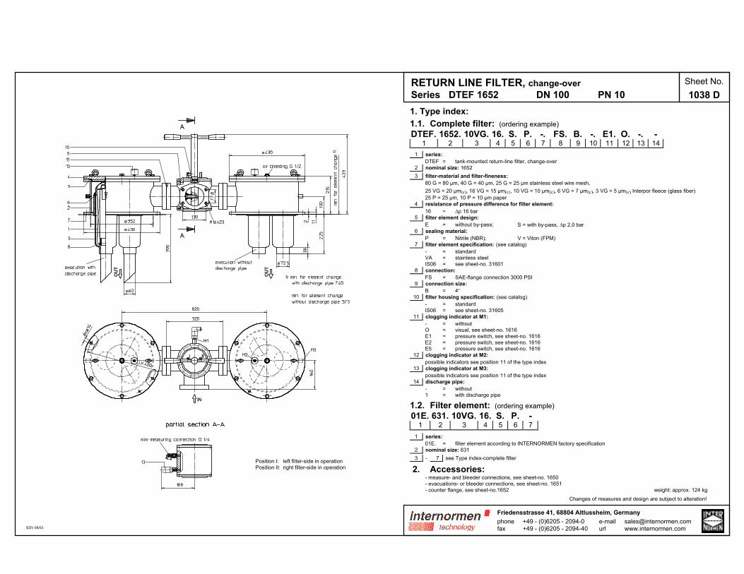
RETURN LINE FILTER, change-over
Series DTEF 1652 DN 100 PN 10
Sheet No.
1038 D
Position I: left filter-side in operation
Position II: right filter-side in operation
EDV 08/03
1. Type index:
1.1. Complete filter: (ordering example)
DTEF. 1652. 10VG. 16. S. P. -. FS. B. -. E1. O. -. -1 2 3 4 5 6 7 8 9 10 11 12 13 14
1 series:
DTEF = tank-mounted return-line filter, change-over
2 nominal size: 1652
3 filter-material and filter-fineness:
80 G = 80 µm, 40 G = 40 µm, 25 G = 25 µm stainless steel wire mesh,
25 VG = 20 µm(c), 16 VG = 15 µm(c), 10 VG = 10 µm(c), 6 VG = 7 µm(c), 3 VG = 5 µm(c) Interpor fleece (glass fiber)
25 P = 25 µm, 10 P = 10 µm paper
4 resistance of pressure difference for filter element:
16 = ∆p 16 bar
5 filter element design:
E = without by-pass; S = with by-pass, ∆p 2,0 bar
6 sealing material:
P = Nitrile (NBR); V = Viton (FPM)
7 filter element specification: (see catalog)
- = standard
VA = stainless steel
IS06 = see sheet-no. 31601
8 connection:
FS = SAE-flange connection 3000 PSI
9 connection size:
B = 4“
10 filter housing specification: (see catalog)
- = standard
IS06 = see sheet-no. 31605
11 clogging indicator at M1:
- = without
O = visual, see sheet-no. 1616
E1 = pressure switch, see sheet-no. 1616
E2 = pressure switch, see sheet-no. 1616
E5 = pressure switch, see sheet-no. 1616
12 clogging indicator at M2:
possible indicators see position 11 of the type index
13 clogging indicator at M3:
possible indicators see position 11 of the type index
14 discharge pipe:
- = without
1 = with discharge pipe
1.2. Filter element: (ordering example)
01E. 631. 10VG. 16. S. P. -1 2 3 4 5 6 7
1 series:
01E. = filter element according to INTERNORMEN factory specification
2 nominal size: 631
3 - 7 see Type index-complete filter
2. Accessories:- measure- and bleeder connections, see sheet-no. 1650
- evacuations- or bleeder connections, see sheet-no. 1651
- counter flange, see sheet-no.1652 weight: approx. 124 kg
Changes of measures and design are subject to alteration!
phonefax
+49 - (0)6205 - 2094-0+49 - (0)6205 - 2094-40
Friedensstrasse 41, 68804 Altlussheim, Germany
e-mailurl

3. Spare parts:
item qty. designation dimension article-no.
1 6 filter element 01.E 631 -
2 2 filter head 1)
3 6 filter bowl with discharge pipe 1)
6 filter bowl without discharge pipe 1)
4 2 filter cover 1)
5 2 O-ring 355 x 5 314740 (NBR) 314739 (FPM)
6 6 O-ring 120 x 4 305300 (NBR) 307991 (FPM)
7 2 gasket 430 x 350 x 2 317271 (NBR) 316659 (FPM)
8 2 O-ring 63 x 3,5 311189 (NBR) 311592 (FPM)
9 2 O-ring 150 x 4 313278 (NBR) - (FPM)
10 2 O-ring 24 x 3 303038 (NBR) 304397 (FPM)
11 2 O-ring 110,72 x 3,53 316355 (NBR) 316356 (FPM)
12 1 clogging indicator, visual O see sheet-no. 1616
13 1 pressure switch, electrical E1, E2 or E5 see sheet-no. 1616
1)in case of ordering these spare parts use the complete type index
4. Description:
Return-line filters change-over in the DTEF series are suitable for a working pressure up to 10 bar. Pressure peaks will be absorbed by a sufficient
margin of safety. The DTEF-filters are directly mounted to the reservoir and connected to the return-line.
A rotary slide valve which is integrated in the middle of the housing makes it possible to switch from the dirty filter-side to the clean filter-side
without interrupting operat ion.
The filter element consists of a star-shaped, pleated filter material which is supported on the inside by a perforated core tube and is bonded to the
end caps with a high-quality adhesive. The flow is from outside to inside. Filters finer than 40 µm should use throuw-away elements made of paper
or Interpor fleece (glass fibre). Filter elements as fine as 5 µm (c) are available; finer filter elements on request.
INTERNORMEN-Filters can be used for petroleum-based fluids, HW emulsions, water glycols, most synthetic fluids and lubrication fluids. Consult
factory for specific fluid applications.
INTERNORMEN-Filters elements are known as stable elements which have excellent filtration capabilities and a high dirt retaining capacity,
therefore having a long service life. Due to its practical design, the return-line filter is easy to service.
When changing the filter element a detachable connection between the filter head and the filter bowl prevents a flow back of dirty oil into the tank.
5. Technical data:
temperature range: - 10°C to + 80°C (for a short time + 100°C)
operating medium: mineral oil, other media on request
max. operating pressure: 10 bar
opening pressure by-pass valve: 2,0 bar
connection system: SAE-flange connection 3000 PSI
housing material: C-steel; glass fibre reinforced polyamide
sealing material: Nitrile (NBR) or Viton (FPM), other materials on request
installation position: vertical
volume tank: 2x 22,0 l
Classified under the Pressure Equipment Directive 97/23/EC for mineral oil (fluid group 2), Article 3, Para. 3.
Classified under ATEX Directive 94/9/EC according to specific application (see questionnaire sheet-no. 34279-4).
E 1038 D
6. Symbols:
without by-pass valve with by-pass valve
clogging indicator at M1, M2, M3
visual O electrical
contact maker E1
electrical
contact breaker E5
electrical
contact maker/breaker E2
7. Pressure drop flow curves: Precise flow rates see ‘INT-Expert-System Filter’, respectively
∆p- curves; depending on filter fin eness and viscosity.
8. Test methods: Filter elements are tested according to the following ISO standards:
ISO 2941 Verification of collapse/burst resistance
ISO 2942 Verification of fabrication integrity
ISO 2943 Verification of material compatibility with fluids
ISO 3723 Method for end load test
ISO 3724 Verification of flow fatigue characteristics
ISO 3968 Evaluation of pressure drop versus flow characteristics
ISO 16889 Multi-pass method for evaluating filtration perfo rmance
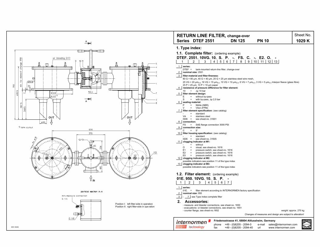
RETURN LINE FILTER, change-over
Series DTEF 2551 DN 125 PN 10
Sheet No.
1029 K
EDV 08/06
Position I: left filter-side in operation
Position II: right filter-side in ope ration
1. Type index:
1.1. Complete filter: (ordering example)
DTEF. 2551. 10VG. 10. S. P. -. FS. C. -. E2. O. -1 2 3 4 5 6 7 8 9 10 11 12 13
1 series:
DTEF = tank-mounted return-line filter, change-over
2 nominal size: 2551
3 filter-material and filter-fineness:
80 G = 80 µm, 40 G = 40 µm, 25 G = 25 µm stainless steel wire mesh,
25 VG = 20 µm(c), 16 VG = 15 µm(c), 10 VG = 10 µm(c), 6 VG = 7 µm(c), 3 VG = 5 µm(c) Interpor fleece (glass fibre)
25 P = 25 µm, 10 P = 10 µm paper
4 resistance of pressure difference for filter element:
10 = ∆p 10 bar
5 filter element design:
E = without by-pass
S = with by-pass, ∆p 2,0 bar
6 sealing material:
P = Nitrile (NBR)
V = Viton (FPM)
7 filter element specification: (see catalog)
- = standard
VA = stainless steel
IS06 = see sheet-no. 31601
8 connection:
FS = SAE-flange connection 3000 PSI
9 connection size:
C = 5“
10 filter housing specification: (see catalog)
- = standard
IS06 = see sheet-no. 31605
11 clogging indicator at M1:
- = without
O = visual, see sheet-no. 1616
E1 = pressure switch, see sheet-no. 1616
E2 = pressure switch, see sheet-no. 1616
E5 = pressure switch, see sheet-no. 1616
12 clogging indicator at M2:
possible indicators see position 11 of the type index
13 clogging indicator at M3:
possible indicators see position 11 of the type index
1.2. Filter element: (ordering example)
01E. 950. 10VG. 10. S. P. -1 2 3 4 5 6 7
1 series:
01E. = filter element according to INTERNORMEN factory specification
2 nominal size: 950
3 - 7 see Type index-complete filter
2. Accessories:- measure- and bleeder connections, see sheet-no. 1650
- evacuations- or bleeder connections, see sheet-no. 1651
- counter flange, see sheet-no.1652 weight: approx. 275 kg
Changes of measures and design are subject to alteration!
phonefax
+49 - (0)6205 - 2094-0+49 - (0)6205 - 2094-40
Friedensstrasse 41, 68804 Altlussheim, Germany
e-mailurl
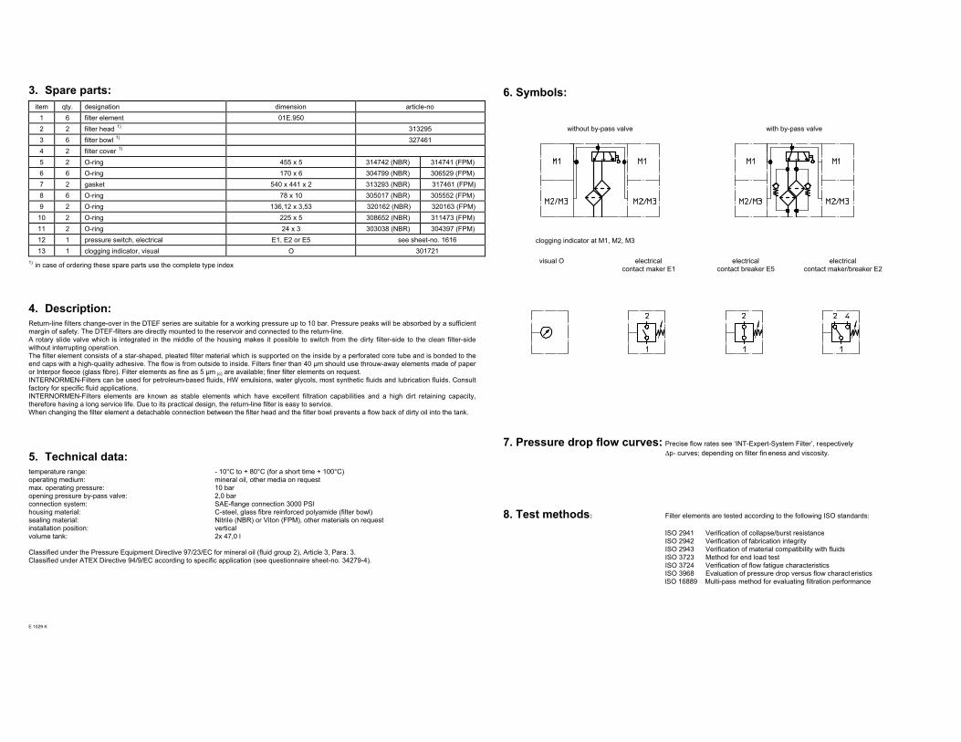
3. Spare parts:
item qty. designation dimension article-no
1 6 filter element 01E.950
2 2 filter head 1)
313295
3 6 filter bowl 1)
327461
4 2 filter cover 1)
5 2 O-ring 455 x 5 314742 (NBR) 314741 (FPM)
6 6 O-ring 170 x 6 304799 (NBR) 306529 (FPM)
7 2 gasket 540 x 441 x 2 313293 (NBR) 317461 (FPM)
8 6 O-ring 78 x 10 305017 (NBR) 305552 (FPM)
9 2 O-ring 136,12 x 3,53 320162 (NBR) 320163 (FPM)
10 2 O-ring 225 x 5 308652 (NBR) 311473 (FPM)
11 2 O-ring 24 x 3 303038 (NBR) 304397 (FPM)
12 1 pressure switch, electrical E1, E2 or E5 see sheet-no. 1616
13 1 clogging indicator, visual O 301721
1)in case of ordering these spare parts use the complete type index
4. Description:
Return-line filters change-over in the DTEF series are suitable for a working pressure up to 10 bar. Pressure peaks will be absorbed by a sufficient
margin of safety. The DTEF-filters are directly mounted to the reservoir and connected to the return-line.
A rotary slide valve which is integrated in the middle of the housing makes it possible to switch from the dirty filter-side to the clean filter-side
without interrupting operat ion.
The filter element consists of a star-shaped, pleated filter material which is supported on the inside by a perforated core tube and is bonded to the
end caps with a high-quality adhesive. The flow is from outside to inside. Filters finer than 40 µm should use throuw-away elements made of paper
or Interpor fleece (glass fibre). Filter elements as fine as 5 µm (c) are available; finer filter elements on request.
INTERNORMEN-Filters can be used for petroleum-based fluids, HW emulsions, water glycols, most synthetic fluids and lubrication fluids. Consult
factory for specific fluid applications.
INTERNORMEN-Filters elements are known as stable elements which have excellent filtration capabilities and a high dirt retaining capacity,
therefore having a long service life. Due to its practical design, the return-line filter is easy to service.
When changing the filter element a detachable connection between the filter head and the filter bowl prevents a flow back of dirty oil into the tank.
5. Technical data:
temperature range: - 10°C to + 80°C (for a short time + 100°C)
operating medium: mineral oil, other media on request
max. operating pressure: 10 bar
opening pressure by-pass valve: 2,0 bar
connection system: SAE-flange connection 3000 PSI
housing material: C-steel, glass fibre reinforced polyamide (filter bowl)
sealing material: Nitrile (NBR) or Viton (FPM), other materials on request
installation position: vertical
volume tank: 2x 47,0 l
Classified under the Pressure Equipment Directive 97/23/EC for mineral oil (fluid group 2), Article 3, Para. 3.
Classified under ATEX Directive 94/9/EC according to specific application (see questionnaire sheet-no. 34279-4).
E 1029 K
6. Symbols:
without by-pass valve with by-pass valve
clogging indicator at M1, M2, M3
visual O electrical
contact maker E1
electrical
contact breaker E5
electrical
contact maker/breaker E2
7. Pressure drop flow curves: Precise flow rates see ‘INT-Expert-System Filter’, respectively
∆p- curves; depending on filter fin eness and viscosity.
8. Test methods: Filter elements are tested according to the following ISO standards:
ISO 2941 Verification of collapse/burst resistance
ISO 2942 Verification of fabrication integrity
ISO 2943 Verification of material compatibility with fluids
ISO 3723 Method for end load test
ISO 3724 Verification of flow fatigue characteristics
ISO 3968 Evaluation of pressure drop versus flow charact eristics
ISO 16889 Multi-pass method for evaluating filtration performance