Embed Size (px)
Citation preview

User Guide
Version 1.0.24.1r4
1

CONTENTS
1. Safety2. Introduction3. Installation4. Wiring5. Configuration6. First flight7. Problems and solutions8. Thanks
2

1. SAFETY
R/C models such as helicopters are not toys! It is necessary to check all the manufacturer instructions of the model, comply with local laws, carry out preventive checking of the model and repair all mechanical and electrical concerns and failures immediately.
Rotor blades and propellers rotate at high speed and can lead to serious injury to persons or damage to the model if not respected.
If you encounter any problems, contact your model shop or experienced modelers.
Especially pay attention to your own safety and the safety of others. Never fly amongst or over people, animals, or on private property without prior authorisation from the land owner.
Fly only in safe places where no additional damage is possible to other objects, because the model can become unmanageable for various reasons, such as failure of electronics, mechanical failure, pilot error or radio interference.
Do not try to control crashed models nor repair damaged parts, always replace them with new ones.
Never fly the model with excess vibrations, it may cause unwanted flight characteristics or become uncontrollable. Find the source of the vibrations and fix the problem.
Spirit is not an autopilot, it is necessary to have knowledge of flying R/C models. The system is only designed to improve flight performance.
We recommend using R/C simulators designed for training before the first flight.
The user takes full responsibility for any damage or injury caused whilst flying an R/C model equipped with one of our devices. The manufacturer is not able to guarantee the conditions in which the unit is being used.
3

2. INTRODUCTION
Spirit is a device for stabilising R/C models such as flybarless helicopters, features include electronic paddle simulation, vibration logging, support for various Tx/Rx types and a rudder gyro for those who want to continue using a mechanical flybar.
Thanks to flybarless mechanics, the system improves the efficiency and maneuverability of the helicopter and it's stability whilst also extending flight times.
Flight characteristics are easily customisable according to your preferences, from stable flight for beginners to demanding acrobatics with maximum agility for experts.
Because the Spirit uses the most advanced technology, the model can be controlled very precisely even under harsh conditions such as strong winds whilst maintaining a constant pirouette.
This user guide will help you to properly mount the unit on a model and carry out the configuration step by step to prepare it for the first flight. It is very important to carefully adjust everything to make your first flight as pleasant and trouble free as possible.
Please check our website spiritsystem.com for downloading new firmware and software updates.
You can also raise any questions in our forum.
4

3. INSTALLATION
The mounting of Spirit plays an important role for the correct operation of your model.
Find a suitable location where vibrations are as low as possible that locationis usually given by the manufacturer for mounting the gyro.
A very significant factor is that the unit should be positioned exactly perpendicular to each rotational axes.The unit can be mounted in two different positions. Depending on your preference and available space it can be:
HorizontallyThe unit can be mounted horizontally so the connectors face upwards. It can be rotated by 180° on the yaw axis so that the connectors can be situated to either the front or the rear of the model.
5

VerticallyThe unit is located on the side so the connectors are also at one of the sides.It can be rotated by 180° in yaw axis so that the connectors can be situated to either the front or the rear of the model.The unit must always be positioned parallel to the longitudinal axes of the model.
In order to better insulate against any vibrations from the model, it is necessary to choose the right doublesided tape. It should limit any transmission of vibrations from the model to the Spirit which may produce undesirable flight characteristics. Vibrations may be caused not only from incorrectly balanced blades or propellers, but also from damaged bearings, bent shafts and other mechanical issues.
6
4. WIRING
Wiring to the unit depends on the type of receiver used.Spirit can be set up as a standalone tail gyro or as a flybarless system.
NOTESpirit is preprogrammed to 1520µs servo neutral impulse and 50 Hz frequency – please ensure you have the correct servo parameters specified by your servo manufacturer.
If the neutral impulse of your servo/s is different to the above, such as 760µs, do not connect this servo yet as it could be damaged.
Some connectors have nonstandard dimensions that could interfere with neighboring connectors after plugging in the unit. As a solution, we recommend replacing these connectors with JR or Futaba connectors.
Never plug a connector for powering the unit into the SYS or ELE/PIT/AIL positions or you may risk damaging the unit.
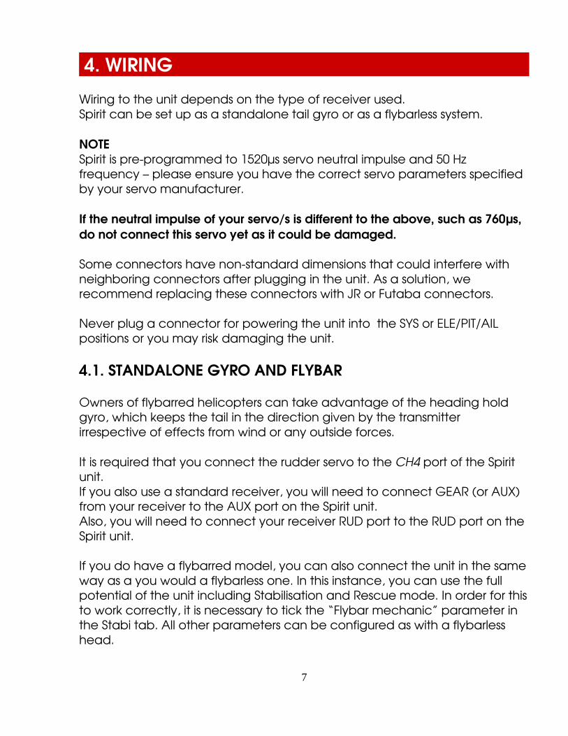
4.1. STANDALONE GYRO AND FLYBAR
Owners of flybarred helicopters can take advantage of the heading hold gyro, which keeps the tail in the direction given by the transmitter irrespective of effects from wind or any outside forces.
It is required that you connect the rudder servo to the CH4 port of the Spirit unit.If you also use a standard receiver, you will need to connect GEAR (or AUX) from your receiver to the AUX port on the Spirit unit.Also, you will need to connect your receiver RUD port to the RUD port on the Spirit unit.
If you do have a flybarred model, you can also connect the unit in the sameway as a you would a flybarless one. In this instance, you can use the full potential of the unit including Stabilisation and Rescue mode. In order for thisto work correctly, it is necessary to tick the “Flybar mechanic” parameter in the Stabi tab. All other parameters can be configured as with a flybarless head.
7

4.2. FLYBARLESS
Owners of flybarless helicopters can take advantage of the full capabilities of the Spirit unit. The Spirit will stabilise the model on all axes and also make it less prone to wind, extend flight times and increase the agility of the model.Flight characteristics should be more stable which will allow the pilot to carry out even the most challenging maneuvers.
Unlike flybarred helicopters, the cyclic servos on an FBL helicopter are more directly connected to the rotor head and blades, so demands on the servos are significantly higher. They should be stronger to cope with this and also faster to respond as quickly as possible to any commands the Spirit unit sends them.Flybarless rotor blades are also different from blades designed for flybarred models. For optimum flight characteristics it is recommended to use them.When using the Spirit unit as a flybarless system, all servos should be connected in the corresponding positions:
CH1 (aileron) CH2 (elevator) CH3 (aileron/pitch) CH4 (rudder).
For standard receivers it is necessary to use two normal and one special cable. Three connectors should be plugged into the receiver and the end ofthis cable to the unit.
8

4.3. CONNECTION OF STANDARD RECEIVER (PWM)
The unit is powered by two cables from the receiver connected to AUX and RUD positions.
Never plug a connector for powering the unit to SYS or ELE/PIT/AIL ports.
9
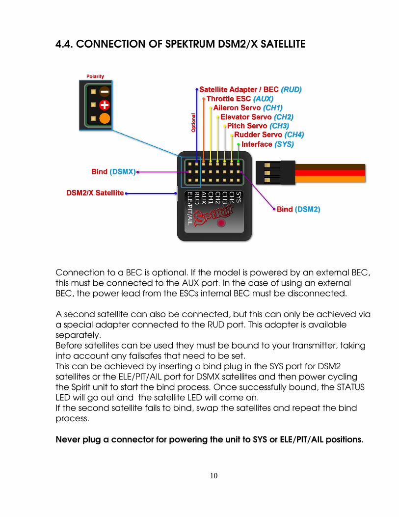
4.4. CONNECTION OF SPEKTRUM DSM2/X SATELLITE
Connection to a BEC is optional. If the model is powered by an external BEC,this must be connected to the AUX port. In the case of using an external BEC, the power lead from the ESCs internal BEC must be disconnected.
A second satellite can also be connected, but this can only be achieved viaa special adapter connected to the RUD port. This adapter is available separately.Before satellites can be used they must be bound to your transmitter, taking into account any failsafes that need to be set.This can be achieved by inserting a bind plug in the SYS port for DSM2 satellites or the ELE/PIT/AIL port for DSMX satellites and then power cycling the Spirit unit to start the bind process. Once successfully bound, the STATUS LED will go out and the satellite LED will come on.If the second satellite fails to bind, swap the satellites and repeat the bind process.
Never plug a connector for powering the unit to SYS or ELE/PIT/AIL positions.
10

4.5. CONNECTION OF FUTABA SBUS RECEIVER
NOTEWhen using SBUS it is necessary to use an inverter that replaces the cable between the receiver and the Spirit unit RUD port. This inverter cable can be purchased separately. When using this type of receiver it is necessary to connect the throttle cable directly to the receiver and not the Spirit unit.Connection to a BEC is optional. For models of 500 size and larger it is recommended to use dual power supply cables due to the increased powerconsumption. That means besides the inverter, additional power supply cables should be connected to the AUX port.
Never plug a connector for powering the unit to SYS or ELE/PIT/AIL ports.
11

4.6. CONNECTION OF JETI EXBUS RECEIVER
When using this type of receiver it is necessary to connect the throttle cable directly to the receiver and not the Spirit FBL controller.
NOTEConnection to a BEC is optional. For models of 500 size and larger it is recommended to use dual power supply cables due to the increased powerconsumption. That means besides the inverter, additional power supply cables should be connected to the AUX port.
Never plug a connector for powering the unit to SYS or ELE/PIT/AIL ports.
12
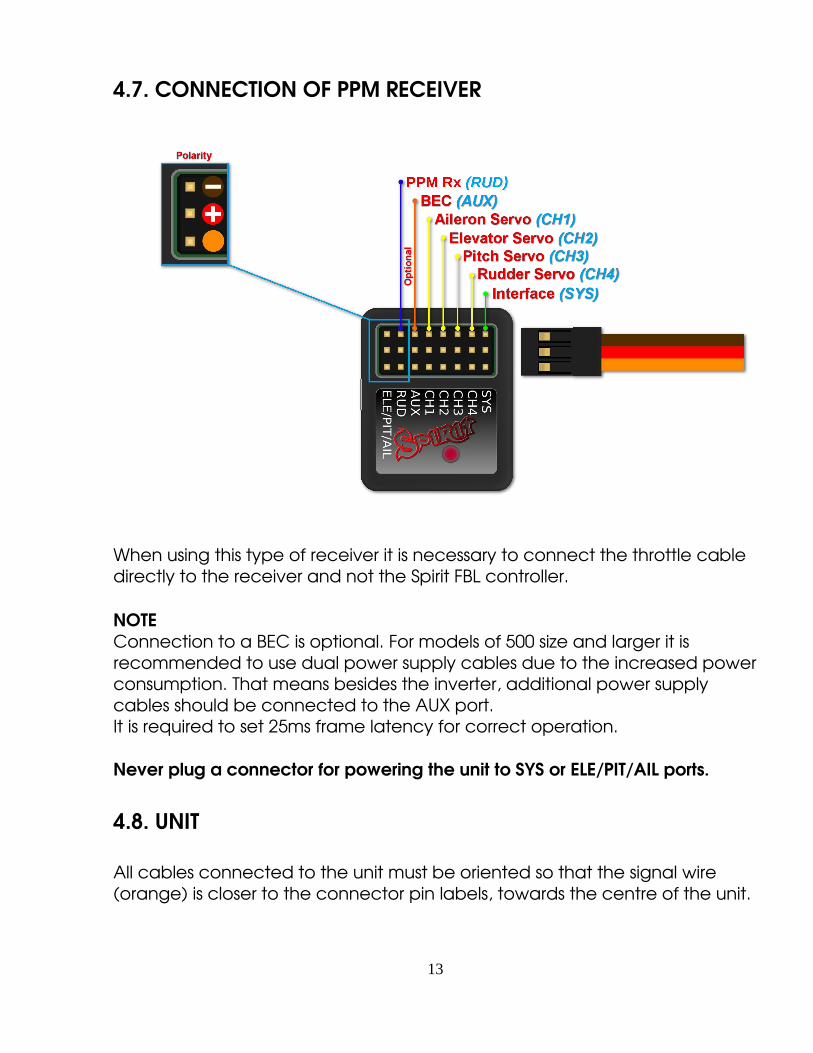
4.7. CONNECTION OF PPM RECEIVER
When using this type of receiver it is necessary to connect the throttle cable directly to the receiver and not the Spirit FBL controller.
NOTEConnection to a BEC is optional. For models of 500 size and larger it is recommended to use dual power supply cables due to the increased powerconsumption. That means besides the inverter, additional power supply cables should be connected to the AUX port.It is required to set 25ms frame latency for correct operation.
Never plug a connector for powering the unit to SYS or ELE/PIT/AIL ports.
4.8. UNIT
All cables connected to the unit must be oriented so that the signal wire (orange) is closer to the connector pin labels, towards the centre of the unit.
13

5. CONFIGURATION
Configuration is the next and one of the most important steps for correct operation of the system.Configuration is performed using the software, which combines efficiency and simplicity whilst offering a set of adjustable parameters, including advanced parameters.
5.1. CONNECTION TO PC
Before you begin the actual configuration it is necessary to connect the system to a computer via a USB port. Depending on the operating system and computer, a driver may need to be installed after connecting the cableto the USB port.
Once connected and the driver is installed successfully a new virtual COM port should be visible in the software and device manager.
MS WINDOWSInstall the driver via the software installer. This process will be described in a following section.
APPLE MAC OS XDownload and install the driver from the following URL:http://spiritsystem.com/dl/driver/SiLabsUSBDriverDisk.dmg
GNU/LINUXNothing needs to be installed.
14

5.2. CONNECTION WITH THE UNIT
If you have already attached the USB interface to your computer, next connect the interface cable to the SYS port of the Spirit FBL unit.The Spirit FBL unit can not be powered from the USB cable/SYS port so it is necessary to power it from either the receiver, a BEC or an external battery pack.The RUD and AUX ports are used to power the Spirit FBL unit and if using a BEC or battery pack it is suggested to connect to these ports with a voltage between 3V and 15V.The middle wire must be positive voltage.
Never plug a connector for powering the unit to SYS or ELE/PIT/AIL ports.
NOTEIf the unit is not configured yet (e.g. a new unit) it is advised to not connect any servos.
5.3. CONFIGURATION SOFTWARE INSTALLATION
The configuration software is available for MS Windows, Apple Mac OS X, GNU/Linux and Android platforms and is available from the spirit website at spiritsystem .com
Below are the installation instructions for the supported platforms.
MS WINDOWSRun the installer and go through the wizard.If the driver is not installed yet, you will be given the option to do so during the installation process.The installer will go through all the necessary steps to prepare your computer for running the configuration software, upon completion of the installation process, the configuration software can be launched from your desktop or program list, called “Spirit Settings”.
APPLE MAC OS XInstall the downloaded software by opening the DMG file and then moving the content to your Applications folder. Configuration software can be launched from the Applications folder with “Spirit settings“.
15

GNU/LINUXExtract all the files from the downloaded archive to, for example, your home directory.Configuration software can be launched from the newly created directory with the file “settings.sh“.
5.4. CONFIGURATION SOFTWARE
Once the software is installed, ensure your Spirit unit is connected via USB to the SYS port, powered on and initialized (LED lights are on), then run the software on your computer.
NOTEConfiguration software should be started after the unit has initialised.Whenever the Spirit FBL is initialised (status LED is on) and connected, you can make adjustments to the settings.Configuration during flight is not possible due to the associated safety risks.
PROBLEMS WITH WINDOWSIf the configuration software is unable to detect a valid COM port, you can try starting the software as Administrator. Alternatively check the COM port number, if the value is too high try reconfiguring the port number (Silabs device) to, for example, COM1 – COM4. For notebooks it is also worth disabling any USB power saving featuresin Device manager.
5.5. SOFTWARE USAGE
After successful connection of the Spirit FBL unit, all configuration features should be accessible. If not, try to either choose another COM port (Device) or try to restart the software, disconnecting the unit from the power supply and repeating the procedure.
Make sure the software is launched after the unit has initialised.
16

5.5.1 CONNECTION TABThis tab indicates the current status of the connection, informs you about thecurrent version of the firmware, displays the serial number of the unit and allows you to change the COM port. In addition it features a wizard for initial setup.
We recommend using this wizard, as it will guide you through a basic setup in the easiest and simplest way.
17

5.5.2. GENERAL
If you have already set up the unit using the wizard, you can make additional adjustments to your setup here. All values relate to the settings you selected in the wizard.
NOTEWhenever parameters are changed, the new value is immediately applied. Unless settings are saved, after disconnecting the power supply all unsaved changes will be lost, see Backup tab.
18

PositionSelects the position in which the unit is attached to the model.See section 3. Installation.
MixSelect the swash type of your model. In most cases it is CCPM 120°.Mixing in the transmitter must be turned off. It must be to set H1 type.
ReceiverSelect the type of receiver you are usingPWM – standard receiver.PPM single line connection.Spektrum DSM2/DSMX DSM2/DSMX satellite.Futaba SBUS receiver connected via SBUS.Jeti EXBUS receiver connected via EXBUS.
Flight styleSets how the model will behave in flight.This parameter is used to control and adapt flight behavior according to the requirements of the pilot.
Lower values mean that the model will behave in a more consistent, controlled manner and will feel more robotic.Higher values mean a more natural behavior. The response to stick movements will be more flybarlike.
This parameter does not affect how stable the model will be.Most pilots prefer default value 4.
19

5.5.3 DIAGNOSTIC TAB
Once the settings in the previous tab have been completed, it is now recommended to make any adjustments and changes required in the transmitter.Each transmitter is different and the centre of the channel is never exactly the same. Wear and environmental influences can also have an effect causing the centre of the channels to fluctuate.Another consideration is the maximum and minimum value of each channel.Here, you adjust your throws using your transmitter's servo endpoint adjustments.
20

NOTEFor proper operation of the unit, it is necessary to check the values of aileron,elevator and rudder channels. These three channels must be centred at approximately 0%.The unit automatically detects the neutral position during each initialization.Do not use subtrim or trim functions on your transmitter for these three channels, as the Spirit FBL unit will consider these as an input command.Ensure all subtrims and trims are zeroed.
It is also recommended to set the maximum and minimum values.Test the minimum and maximum throws for all channels, if these values are not equal to 100% and 100% in the diagnostic tab it is necessary to adjust your transmitter endpoints to correct this.You will need to adjust this for both directions via the dual rate or travel adjust/endpoint function in your transmitter.
Besides the aileron, elevator and rudder channels, it is also necessary to check the pitch channel. For this channel it is acceptable to use subtrim to achieve a centre value of 0%.When a collective pitch curve in range of 100% to 100% is used, the middle of the stick should be show 0%.
After these adjustments, everything should be configured with regards to thetransmitter.If some channels oscillate around the centre, it may mean wear of the transmitter potentiometers. This can be compensated for by increasing stick deadband in the Advanced tab, covered later.
If the values in the aileron, elevator, or rudder channels are marked in bold, itis recognized as a command to move/rotate the axes, check your trims and subtrims to ensure they are zero or increase your stick deadband, covered inthe Advanced tab.
21

SPECTRUM ANALYSER
The Spectrum analyser is a tool for measuring the amount of vibrations on the model.It is a diagnostic tool designed to determine which rotating part is causing a problem. With this information you can easily identify and fix any problems with your model.
It is possible to measure vibrations in three separate axes:• X – elevator axes• Y – aileron axes• Z – rudder axes
The live graph shows frequencies for the currently selected axes. This enablesyou to see both the frequency and magnitude of the vibration on the selected axes.Vibrations are transmitted to each axes dependent on several various factors. Frequencies and magnitude are dependent on the model construction. Generally, the vibrations are the highest on Y axes (aileron) but we recommend you check all axes each time you are doing measurement however vibrations should not exceed 50% for all axes at any time.In the case vibrations are at 90% or more, the model has an issue that needs to be rectified. Should the magnitude exceed 90% on any of the given axes, it is recommended to fix whatever issue is causing these extreme vibrations before flying the model. Even though Spirit FBL unit is highly resistant to vibrations, these could cause unwanted interactions with the Spirit FBL unit and could also cause mechanical failure of the model. Such high vibrations can cause Loctite to fail and other mechanical parts to break.
Vibration levels:• Vibrations up to 50% vibrations at a normal and acceptable level• Vibrations between 50% and 90% raised vibration levels• Vibrations exceeding 90% extreme vibration levels
22
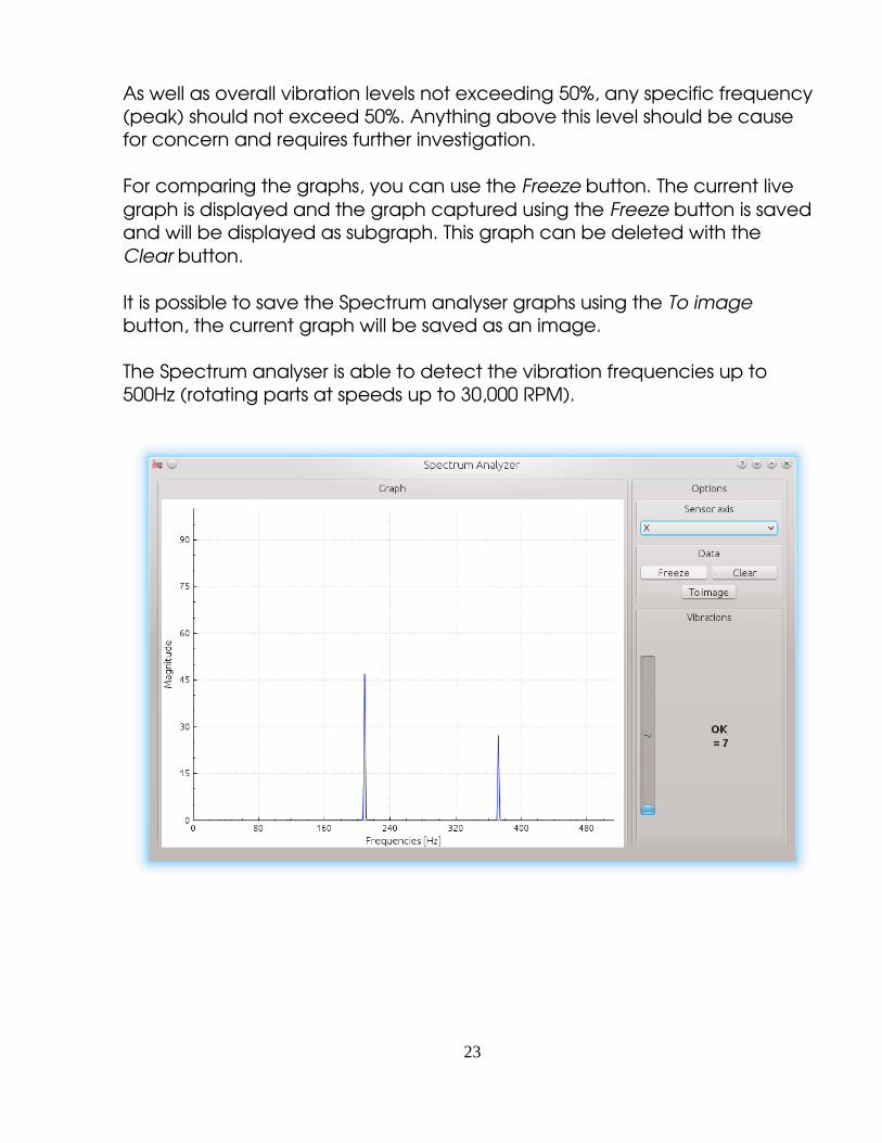
As well as overall vibration levels not exceeding 50%, any specific frequency (peak) should not exceed 50%. Anything above this level should be cause for concern and requires further investigation.
For comparing the graphs, you can use the Freeze button. The current live graph is displayed and the graph captured using the Freeze button is saved and will be displayed as subgraph. This graph can be deleted with the Clear button.
It is possible to save the Spectrum analyser graphs using the To image button, the current graph will be saved as an image.
The Spectrum analyser is able to detect the vibration frequencies up to 500Hz (rotating parts at speeds up to 30,000 RPM).
23

Measurement procedure
1. Remove main and tail blades from the model. 2. Place the model on a suitable surface (e.g. carpet, grass). 3. Set blade pitch at approximately 0° on both main and tail rotors. 4. Run the Spectrum analyser (this also freezes all servos). 5. Spin up the motor to usual flight RPM. 6. Switch between the X, Y and Z axes, saving an image of each. 7. Check vibrations in all axes. 8. Stop the motor.
Recognizing vibrations
To recognize which component or part is causing abnormal vibrations it is necessary to determine the speed of the highest peaks. The main rotor will have the lowest speed and the tail rotor speed will be approximately 4.5x higher. Generally, the smaller the size of the model, the higher the headspeed.
In order to find out which part of the model is causing the unwanted vibrations, move cursor to the peak and check the head speed (RPM). The speed of the main rotor is usually in the range of 1500 to 3500 RPM. Therefore,if the speed is within this range, it is likely that there is a problem with the main gear, shaft, main shaft bearings or rotor head itself.
Most excessive vibrations are usually, although not always, tail related. To check if there are vibrations coming from the tail you should find the frequency peak that is approximately 4.5x higher than the frequency of the main rotor.
Once you identify which part of the helicopter is causing the unwanted vibrations, you can gradually dismantle the suspect assembly, repeating the measurement process until the vibration disappears. Once the vibration levels have dropped to an acceptable level, you have found the suspect component and can replace it.
Measuring with tail blades installed carries some safety concerns and will also show increased levels of vibration.
24

LOG VIEWER
The log is used to record events during flight. If a problem occurs and the reason isn't immediately known or evident, checking the log can help in identifying the issue.
It works in such a way that it records various events from the time the unit is powered on. If an event occurred you can see this in the log, reporting to the log is done every 10sec. When you click the Open log button you can see the current flight log which contains all the events from the last flight. When the power is disconnected, the log is cleared.
In the case of a major problem occurring during the flight the log is then saved permanently to the unit's memory and remains there until such time asthe log is opened.If there is a saved log in memory, the user is advised with the message “Log from previous flight is available!” and the log from the flight when the problem occurred is opened. For example, when a signal is lost or the power supply failed you can find this in the log. The log from the first flight where themajor problem occurred is always saved. If this is not opened, then it will not be overwritten with a newer one.
The log can contain the following events:
Good Health Message:The model is in good condition. The unit did not recognize any
problems.
Calibration Finished:Sensor calibration was successful.
Cyclic Ring Activated:Cyclic achieved its maximum tilt angle. This indicates the
model was unable to do the desired correction as necessary. In most cases it is not relevant. But it is possible that the value of the Cyclic Ringparameter is too low and the model can't rotate as fast as intended in the aileron/elevator axes. Alternatively, a too high value for rotational speed is configured. It is also possible that in fast forward flight the model can pitchup rapidly. We recommend to set this parameter as high as mechanically possible.
25

Rudder Limit Reached:The rudder servo reached its configured limit. When this event
occurs before or after a flight it is not a problem. If you see this during flight it indicates that the rudder did not operate correctly. In most cases it is visible during flight as poor rudder response or “blow out”. If the model is set up correctly then it could be due to low rudder efficiency such as the tail blades being too short or headspeed too low. There is also the possibility of a mechanical issue or with the rudder limits being inadequate.
Receiver Signal Lost:Signal lost suddenly. This problem should not occur at any time
and must be resolved before the next flight. There could be a problem with the receiver and/or transmitter antennas. It could be a faulty receiver cable or the connection between the unit and receiver.In some cases signal loss can happen because of electrostatic discharge caused by static build up, this usually occurs in belt driven helicopters.
Main Loop Hang Occurred:The main loop was delayed. This can happen when wiring is
incorrect or there is abnormal electrical noise interference with the unit, for example, from a BEC. If using the configuration software it could mean the link to the Spirit FBL unit is slower than it should be.
Power Voltage is low:Power supply voltage is lower than 2.9V. This mean you have to
use BEC that is capable of handling higher loads.In rare cases it could be faulty connections in cables.
All reviewed logs are saved as PDF files into Documents directory.
26

5.5.4 SERVOS TAB
This tab is used for servo configuration, care should be taken to ensure correct frequencies are used and that the directions are set correctly.
TypeIn this section, set the values for neutral pulse and frequency according to your servo manufacturers specifications.For analog servos the frequency is usually a maximum of 60Hz.
27

Subtrim (tuning)Ideally, without the rotor head installed, use a swash leveler to align the swash and servo horns so that the swashplate and servo horns are horizontal and perpendicular to the main shaft.This is done by ticking the item Subtrim (tuning). This will put the Spirit FBL unit into a special mode where the collective position will be neutral with the servos centred. In addition, stabilisation will be disabled.Servos can easily be adjusted at this time. When completed, the swashplate should be exactly perpendicular to the main shaft and in addition collective pitch should be at 0° (it is possible to measure the pitch angle using a pitch gauge with rotor head and blades attached).
In most cases, it is also necessary for servo horns to be perpendicular to the main shaft.All servos, i.e., CH1, CH2, CH3 and CH4, are set separately on individual sliders. CH1 and CH3 are the aileron servos. CH2 controls the elevator and CH4 controls the rudder.
It is also necessary to set the subtrim and mechanics of the rudder so that the servo horn is perpendicular to its case and rudder pitch is at 0°.This setting will affect rudder stop performance.
Once set up, untick the Subtrim (tuning) check box to turn off this special mode.
NOTEAfter exiting the special mode, stabilisation and rudder will work again.Be sure your collective pitch channel is configured correctly in the transmitter.That means you should see 100% to 100% in the diagnostic tab.Double check that 0% in diagnostic tab corresponds with middle position of your collective/throttle stick (with linear 100% 100% collective pitch curve).
28

Cyclic servos reverseChoose which servos should have their direction of motion reversed. While changing the collective pitch all servos should move in same direction.
The options available are:Without reverse all servos without reversingCH3 – CH3 servo reversedCH2 – CH2 servo reversedCH2 & CH3 – CH2 and CH3 are reversed
If you cannot obtain the correct collective direction of travel in this section, try reversing your pitch servo in your transmitter and then adjust your channelreversing in the software as necessary.
Servo travel correctionHere, you are able to modify and correct travel for each servo individually. Some servos are not very accurate in regards to travel at their limits and this inaccuracy may have a negative impact on flight characteristics. Once in this section of the software, the unit switches to a mode for doing these corrections.It is expected that in the previous step Subtrim (tuning) the swashplate was set at zero collective (0° rotor blades pitch).The procedure is such that you should use a swash leveler to determine whether there is any deviation on any of the servos in the lowest and highest points of collective throw.For both high and low positions, it is necessary to set the values separately – this is the reason for 6 sliders. If the travel is less than required, increase the value. If too much, decrease.
This correction is also useful if there is asymmetric geometry on the helicoptercausing issues such as the inability to achieve equal positive and negative pitch values. In this case, it is necessary to modify the minimum or maximum for all three servos.If you are unsure about your settings, it is better to leave the sliders in the middle, position 0.
29

30
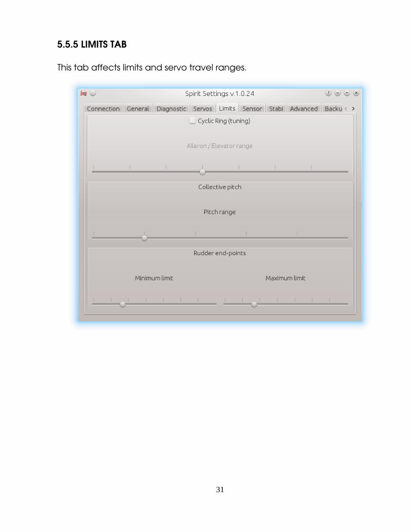
5.5.5 LIMITS TAB
This tab affects limits and servo travel ranges.
31

Cyclic Ring (tuning)This parameter sets the electronic cyclic ring, which allows the model to achieve the largest cyclic ranges without mechanical binding (binding of servo horns, pushrods and linkages).This parameter acts as a socalled electronic Cyclic Ring.
NOTEThe settings here should be done very carefully to avoid damage to the model or it's associated electronics.
First, set your desired collective range, for example, +/12°. We recommend using a 100% to 100% linear collective pitch curve in the transmitter.Now it is time to set the Ail/Ele maximum cyclic pitch range. Try to set the largest possible deflection. This parameter does not directly affect the speedof rotation, but if it is too low, the model may not have consistent pitch and roll rates.This setting should be done with 0° collective pitch. Then carefully check maximum stick deflection in all directions to ensure that mechanical binding does not occur.This should also then be done with maximum and minimum collective pitch.
If you increase the collective pitch range, this parameter must then be checked and in some cases adjusted to insure no binding occurs at your new maximum and minimum pitch ranges.In case the cyclic ring range is insufficient, it is possible that pitchup can happen during fast forward flight (even if the pitchup compensation is at its maximum value). This is because the model will not be able to add sufficient corrections with the configured range.
Rudder Limit Min/Max Sets the minimum and maximum deflection of rudder rotor blades.
We recommend setting these values for both directions to the maximum allowed range by the manufacturer of the helicopter. Otherwise, the rudder may not be able to keep the yaw direction during demanding maneuvers and tail blow outs may occur.
32

5.5.6 SENSOR TAB
This tab is the last important part of the settings which must be configured.
SensitivityThe rotary dial adjusts the gyro sensitivity for aileron, elevator and rudder axes.
Cyclic gain The higher the value is, the higher the accuracy within the control loop. The default value is preconfigured to 50% gain, for most models an optimal value of around 60% is suggested.
33

Rudder Common Gain 100% means no multiplication. This is the recommended value or 550class helicopters and smaller. For bigger helicopters it is often higher,130% could be fine. Transmitter gyro gain should be configured to approximately 60% for the first flight.
ReverseSets compensation direction for each axes separately.The swashplate should tilt as if trying to stay level.Rudder blades should compensate to opposite direction as you rotate the model.
NOTEThis parameter is the most important one, it is necessary to carefully check the orientation of compensation and set it correctly. If this is set incorrectly, the Spirit FBL unit will compensate in the wrong direction, more than likely causing a tip over on spool up.
Rotation speedThe default value is 8 and will favour beginners more, the higher the value, the faster the rate of rotation. This factor also depends on the mechanical linkage ratio or D/R (Dual Rate) in the transmitter and also on the Ail/Ele limit.We recommend to set this parameter within a range of 6 12. Remember that DFC rotor heads tend to rotate faster so it's better to initially start with a lower value.
34

5.5.7 STABI TAB
The Spirit unit offers you the options of model stabilisation and rescue mode.
The stabilisation function, once activated, will recover the model to a horizontal position without any other input from the pilot, this can be used as a “bailout” feature when trying new maneuvers and can help with the learning process.
Rescue mode complements the normal operation of the Spirit unit.If activated, the model will recover to a horizontal position and add collective pitch as per the settings. This function can be used any time when the pilot loses orientation or control of the model.
35

The Spirit unit allows you to assign a stabilisation or rescue mode using the gyro gain channel. 0 100% gain in the transmitter is always heading lock gyro mode and with 100 – 0% gain, you are able to activate stabilisation or rescue mode.This means that instead of normal (rate) mode, it will stay in heading hold gyro mode, plus rescue/stabilisation is activated.So while rescue/stabilisation mode is activated, a gyro gain of 70% is considered as 70%.This behavior can be also observed in the Diagnostic tab.
NOTESome transmitters have a gyro range of 0 to 100% where 50% is the middle zero gain (e.g. Spektrum DX6i). Others use a range of 100% and 100%, where0% is the middle.
FunctionSelect which mode should be activated at negative gyro gains.
Disabled Normal (Rate) gyro mode.Rescue (normal) Recovers the model to a horizontal position – skids always to the ground.Rescue (acro) Recovers the model to a horizontal position, inverted or noninverted, whichever is closer at the time of activation.Stabilisation – stabilisation mode.
WARNINGIn case that pirouette optimization is not configured correctly the rescue andstabilisation mode will not work properly!If using these modes, be sure your helicopter is initialized on a flat plane, not tilted to any side.The rescue mode is very demanding for the BEC. Be sure your BEC can handle such peak loads.
36

Flybar mechanicIf your helicopter is equipped with traditional flybar mechanics, you have to enable this parameter in order to use the stabilisation or rescue modes.All settings are the same for flybarred helicopter except this parameter.
NOTEFlybarless helicopters must be configured with the Flybar mechanic parameter disabled.
Rescue mode collectiveThis determines how quickly the model will recover to a horizontal position.100% means the maximum deflection of the blades, which was configured inthe Servos tab.It is very important to check whether the rescue mode works correctly before the first flight (on the bench without the motor/rotors running), i.e., whether the direction of collective pitch is correct. If collective pitch is not positive while helicopter is on the ground, you have to change to a negativevalue for this parameter.
Sticks prioritySpecifies the amount of control whilst activated, the higher the value, the more the model will react to stick movements.
Direction control rateSpecify the rate of controlling direction for stabilisation mode.Low values are well suited for beginners to get coaxiallike behavior.Higher values are more appropriate for scale flying.
37

5.5.8 Advanced tab
This tab is for more advanced configuration of the Spirit FBL unit. It is recommended that you fully understand these parameters before adjusting them. However, it is essential to set pirouette optimization and geometry. Other parameters, however, depend on the preferences of the pilot.
Stick deadbandDetermines the area around centre stick where the system does not recognize any stick movement.
38

Geometry 6deg (tuning)For proper operation of the Spirit unit, it is necessary to set this parameter correctly. Here, the unit is switched to a special mode for settings 6° of cyclicpitch on the main blades. It is necessary to set the value so that the blades angle is at 6° in the aileron axis. You need to rotate your rotor head with blades to be parallel to the longitudinal axis of the model.A higher value increases the angle; a lower one decreases the angle. Optimal head geometry should be in the range of about 90 – 160. If not in this range, it is recommended to adjust the distance of a ball link on the servo horns or perform other mechanical adjustments.
Pirouette optimization (tuning)If this parameter is ticked, the unit enters a special mode in which you shouldtest and set the correct compensation direction.
Holding the model by the rotor head, rotate it around the yaw axis as if doing a pirouette.The swashplate should stay tilted and pointing in the same direction, it shouldbehave like a compass. That means, the swashplate should be tilted at all times, pointing in one direction whilst you rotate the helicopter.If it does not behave like this, reverse the setting. If this parameter is not configured correctly, your model will not perform stationary pirouettes without additional inputs from the pilot.
When settings are completed, you can easily untick this parameter to exit the special mode.
Tail delayThis is a parameter to smooth rudder movements. It also helps to stabilize the rudder – it is a kind of electronic damping. The faster the servo is, the lower the tail delay should be. For analog servos it is recommended to set this value to around 25. For usual digital servos it is mostly between 15 – 20. For very fast servos (~0.04s/60°) the value is 5. If the value is too high, the rudder could start to oscillate or wag or could cause a slow rudder stop.
39

Pirouette consistencyThis parameter determines the consistency of pirouettes and holding performance. If pirouettes are not consistent during certain maneuvers, increase the value of this parameter.This value is individual for every model, it depends on many factors of your rudder mechanics, head speed, etc. Before setting this parameter, it is recommended to set the gyro gains first.If the value is too high, the tail can oscillate or wag. It can also cause poor stop performance. This value should be between 150 and 175.
Rudder dynamicIf the rudder does not stop correctly, for example it overshoots, this behavior can be changed with this parameter.
6 – default value
The larger the value, the more aggressive the behavior of the tail.If the tail overshoots in stops, the value is too high.This parameter also affects the response speed of the stick movement, a higher value means a faster response.If you cannot reach a symmetric stop on both sides you will need to check the tail is centred at 0°. Alternatively you can lower the rudder limit for that side.
Rudder – RevomixRevomix (tail precompensation) adds rudder in response to collective pitch changes, when the tail needs increased holding. Revomix is independent of the transmitter.By default it is turned off, the user must set the amount required and the direction of the precompensation.The correct direction is determined by the correction needed at full positive or negative pitch to compensate for the main rotor torque. In most cases, the main rotor rotates in a clockwise direction.Allowed values are 10 to 10 with 0 being disabled; in most cases it is not necessary to use this parameter however when using low headspeed, or on helicopters with a poor performing tail, this setting can be used.
40

Cyclic phaseThe value indicates the angle by which the swashplate is virtually rotated.For example a value of 90 will rotate the elevator to aileron. This feature is recommended for models with multiblade rotor heads. For most other models, we recommend a zero value.
Elevator filterThis parameter compensates the elevator bouncing during aggressive maneuvers. The larger the value, more compensation is involved.If this value is too high it can lead to a soft feeling in the elevator.We recommend using the default value of 1 to begin with.
Pitchup compensationIf during fast forward flight the model reacts to inputs too rapidly or if the model pitches up, increase this value until this no longer occurs. If the helicopter pitches up abruptly, this could be caused by a cyclic range that is too low and/or too much collective pitch.In this case, you will have to increase the Ail/Ele range as high as the model can handle without any binding. If this doesn't fix the problem, you can add more pitchup compensation.
Cyclic feed forwardThis parameter is used to set amount of direct feel between your sticks and model helicopter. The higher the value, the more aggressive the model will feel and the faster the model will react to stick movements.Setting this value too high can result in elevator bounce.If the model feels disconnected and there is a lag between stick inputs and the model, try increasing this value.
41

5.5.9 BACKUP TAB
Here, you can save the settings to your Spirit unit before powering off, you can also save the settings to your computer here, Should you need to reloadthem at a later date.
ProfileThis section allows you to Save and Load complete settings of the unit to a specified file.If you have more than one of the same model, it is not necessary to carry outa complete setup again, just load stored settings easily with the Load button.
42

UnitAny changes to the configuration can be saved at any time to the internal flash memory of the unit.To put all settings to a factory defaults, click Factory Settings.
NOTERemember to save the settings each time you want to store the settings permanently. You must press the Save button, otherwise the changes will be lost after the Spirit FBL unit is turned off.
43

5.5.10 UPDATE TAB
If you want to update the firmware, you can do so in this tab.
FirmwareFirst select the data file containing the firmware (*. bin) – Select button.You can get firmware from spiritsystem.com.Once the file is selected, press Flash.The upgrade progress will be displayed here. After completion, a confirmation dialog box should indicate a successful update.Then, unplug the unit from a power source.Upon the next start it will load with the newly flashed firmware.
Configuration of the unit is not changed, so you do not need to save/load it.
44

6. FIRST FLIGHT
If you are sure that the unit is correctly configured, you are ready for your firstflight.
6.1. Preflight control
1. Turn on the transmitter and connect the battery to the model.2. Wait for the initialization, the swashplate jumps.3. Tilt the model, ensure the swashplate is compensating in the correct
direction on all axes.4. Move the tail boom in any direction, tail slider/rudder blades should
compensate in the opposite side.5. Check that input from the transmitter sticks moves the swashplate and
tail in the correct direction.6. Place the model on a flat surface, use the transmitter sticks to level the
swashplate if it isn't already, the tail slider should be approximately in the centre of its travel range.
WARNINGIf you encounter a problem at this point, do not try to take off!
6.2. TAKEOFF
1. Spool up the main rotor to the desired speed we recommend to start with a slightly lower RPM.
2. Slowly increase the collective pitch from zero.3. Try to steer the rudder and check whether it has sufficient gain and
stop performance is good.4. If control is not very precise, slowly add cyclic and rudder gain as
needed.
45

7. PROBLEMS AND SOLUTIONS
Problem description SolutionSwashplate or tail drifts after initialization Check trims and subtrims. Sticks neutral
position must be 0%, see the Diagnosticstab. Increase Stick deadband in Advanced tab.
Rudder or cyclic is not precise Increase cyclic gain and/or increase the gyro gain in the transmitter.Add exponential in the transmitter.
Aggressive cyclic pitch movement leads to rapid, large tail oscillations
Decrease pirouette consistency in the Advanced tab gradually by 10 until the this disappears. Check the tail mechanics for binding.
Model oscillates in elevator or aileron axes
Decrease cyclic gain in Sensor tab.
Tail oscillates rapidly Decrease gyro gain in the transmitter.
Model pirouette rotation is too slow/fast Increase/decrease rotation speed for rudder in Sensor tab.
Servos jitters randomly without external influences
Check the cable connection between the receiver and the unit.
During stationary pirouettes model drifts Check the correct direction of pirouetteoptimization in Advanced tab.
Aggressive elevator stick movement leads to bouncing
Increase elevator filter in Advanced tab and/or decrease cyclic feed forward in Advanced tab.
Cyclic feels is delayed or disconnected Increase cyclic feed forward in Advanced tab.
Rudder stop is not equal for both sides Check rudder servo centre position, rudder mechanics. You can also try to lower rudder limit for the side where bounceback occur.
46

8. THANKS
To all who in any way participated and are participating in the developmentof Spirit, many thanks!
Special thanks to: Adam Kruchina Daniel Beneš Dušan Habada Elke Lalanza James Pizzey Jens Lalanza Martin Přinda Martin Štvrtňa Milan Křivda Milan Pěchovič Petr Čada Petr Koťátko René Štefánik
47

Declaration about conformity
It is hereby confirmed that Spirit unit is being produced according to EMC directive 2004/108/EC, electromagnetic compatibility.
Tomáš Jędrzejek © Spirit System
48