Embed Size (px)
Citation preview
7/21/2019 VCE Vblock™ Systems 300 Physical Planning Guide (Cisco UCS)
http://slidepdf.com/reader/full/vce-vblock-systems-300-physical-planning-guide-cisco-ucs 1/132
Vblock Infrastructure Platforms Series 300
Physical Planning Guide
Version 1.3
August 2011
© 2011 VCE Company, LLC. All Rights Reserved
www.vce.com
7/21/2019 VCE Vblock™ Systems 300 Physical Planning Guide (Cisco UCS)
http://slidepdf.com/reader/full/vce-vblock-systems-300-physical-planning-guide-cisco-ucs 2/132
2 © 2011 VCE Company, LLC. All Rights Reserved.
Revision history Series 300 Physical Planning Guide
Revision history
Date Version Author Revision
August
2011
1.3 LBG Updated for VNXe 3100.
July 2011 1.2 LBG Added total POUs required for each Vblock model and chart showing power plugsand receptacles.
July 2011 1.1 LBG Updated documentation template so WebHelp works on a Mac.
June 2011 1.0 LBG General availability release.
7/21/2019 VCE Vblock™ Systems 300 Physical Planning Guide (Cisco UCS)
http://slidepdf.com/reader/full/vce-vblock-systems-300-physical-planning-guide-cisco-ucs 3/132
3© 2011 VCE Company, LLC. All Rights Reserved.
Series 300 Physical Planning Guide Table of Contents
Table of Contents
Introduction ................................................................................................................................................. 7
Cisco and EMC reference documentation ................................................................................................ 8
Panduit reference documentation ............................................................................................................. 9
Panduit cabinet documentation .............................................................................................................. 9
Panduit POU documentation .................................................................................................................. 9
Physical specifications and requirements ............................................................................................. 11
Physical specifications summary .......................................................................................................... 11
Shipping weights ............................................................................................................................ 11
Cisco Unified Computing System Power Calculator ...................................................................... 11
Blade power consumption .............................................................................................................. 12
Cabinet specifications ........................................................................................................................... 12
Cabinet floor cutout .............................................................................................................................. 14
Power outlet unit specifications ............................................................................................................ 15
POU specifications - North America .............................................................................................. 15
POU specifications - Europe .......................................................................................................... 16
Maximum number of cabinets per Vblock 300 model .................................................................... 16
Total number of required POUs per Vblock configuration ............................................................. 17
Power plugs and receptacles ............................................................................................................... 18
300EX spec if ications and requ irements ................................................................................................. 19
300EX cabinet layouts .......................................................................................................................... 19
300EX maximum configuration (rear) ............................................................................................ 20
300EX CSB cabinet ....................................................................................................................... 21
300EX SE cabinet .......................................................................................................................... 22
300EX component specifications ......................................................................................................... 23
300EX power and heat specifications ............................................................................................ 23
Cisco Unified Computing System Power Calculator ...................................................................... 24
300EX physical specifications ........................................................................................................ 24
300EX CSB maximum thermal and power requirements ..................................................................... 25
300EX SE maximum thermal and power requirements ....................................................................... 26
300EX power calculations .................................................................................................................... 27
300EX 60A-3P SE .......................................................................................................................... 28
300EX 60A-3P CSB ....................................................................................................................... 29
300EX 32A-3P SE .......................................................................................................................... 30
300EX 32A-3P CSB ....................................................................................................................... 31
300EX 30A-3 phase / 60A-1 phase / 16A-3 phase SE1 ................................................................ 32
300EX 30A-3 phase / 60A-1 phase / 16A-3 phase CSB positions 1 and 2 ................................... 33
300EX 30A-3 phase / 60A-1 phase / 16A-3 phase CSB positions 3 and 4 ................................... 34
300FX specif ications and requ irements ................................................................................................. 35
300FX cabinet layouts .......................................................................................................................... 35
7/21/2019 VCE Vblock™ Systems 300 Physical Planning Guide (Cisco UCS)
http://slidepdf.com/reader/full/vce-vblock-systems-300-physical-planning-guide-cisco-ucs 4/132
4 © 2011 VCE Company, LLC. All Rights Reserved.
Table of Contents Series 300 Physical Planning Guide
300FX maximum configuration (rear) ............................................................................................ 36
300FX CSB-A cabinet .................................................................................................................... 37
300FX CSB-B cabinet .................................................................................................................... 38
300FX component specifications .......................................................................................................... 39
300FX power and heat specifications ............................................................................................ 39
Cisco Unified Computing System Power Calculator ...................................................................... 40 300FX physical specifications ........................................................................................................ 40
300FX CSB-A maximum thermal and power requirements ................................................................. 41
300FX CSB-B maximum thermal and power requirements ................................................................. 42
300FX CSE-1 maximum thermal and power requirements .................................................................. 43
300FX 60A-3P power calculations ....................................................................................................... 44
300FX 60A-3P CSB-A.................................................................................................................... 45
300FX 60A-3P CSB-B.................................................................................................................... 46
300FX 60A-3P CSE-1 .................................................................................................................... 47
300FX 32A-3P power calculations ....................................................................................................... 48
300FX 32A-3P CSB-A.................................................................................................................... 49
300FX 32A-3P CSB-B.................................................................................................................... 50 300FX 32A-3P CSE-1 .................................................................................................................... 51
300FX 30A-3P 60A-1P 16A-3P power calculations ............................................................................. 52
300FX 30A-3 phase / 60A-1 phase / 16A-3 phase CSB-A positions 1 and 2................................ 53
300FX 30A-3 phase / 60A-1 phase / 16A-3 phase CSB-A positions 3 and 4................................ 54
300FX 30A-3 phase / 60A-1 phase / 16A-3 phase CSB-B positions 1 and 2................................ 55
300FX 30A-3 phase / 60A-1 phase / 16A-3 phase CSB-B positions 3 and 4................................ 56
300FX 30A-3 phase / 60A-1 phase / 16A-3 phase CSE-1 positions 1 and 2 ................................ 57
300FX 30A-3 phase / 60A-1 phase / 16A-3 phase CSE-1 positions 3 and 4 ................................ 58
300GX specifications and requ irements ................................................................................................. 59
300GX cabinet layouts ......................................................................................................................... 59 300GX maximum configuration (rear) ............................................................................................ 59
300GX CSB-A cabinet ................................................................................................................... 60
300GX CSB-B cabinet ................................................................................................................... 61
300GX CSE-1 cabinet .................................................................................................................... 62
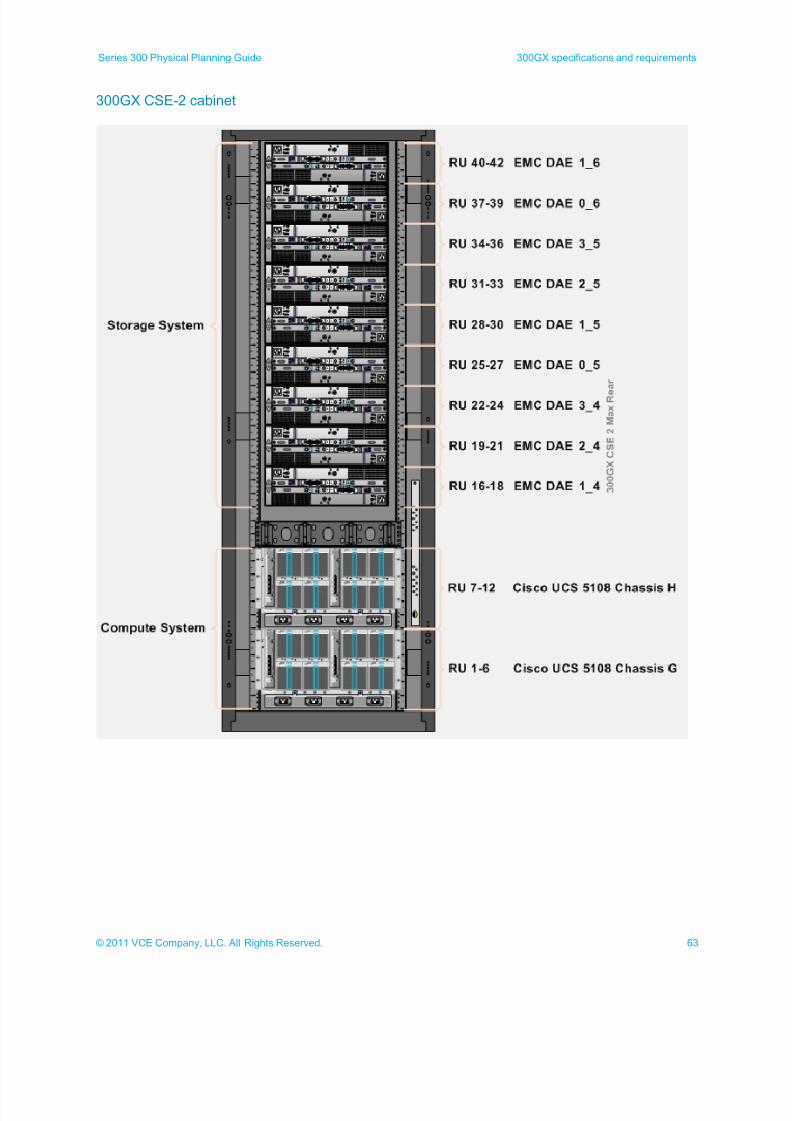
300GX CSE-2 cabinet .................................................................................................................... 63
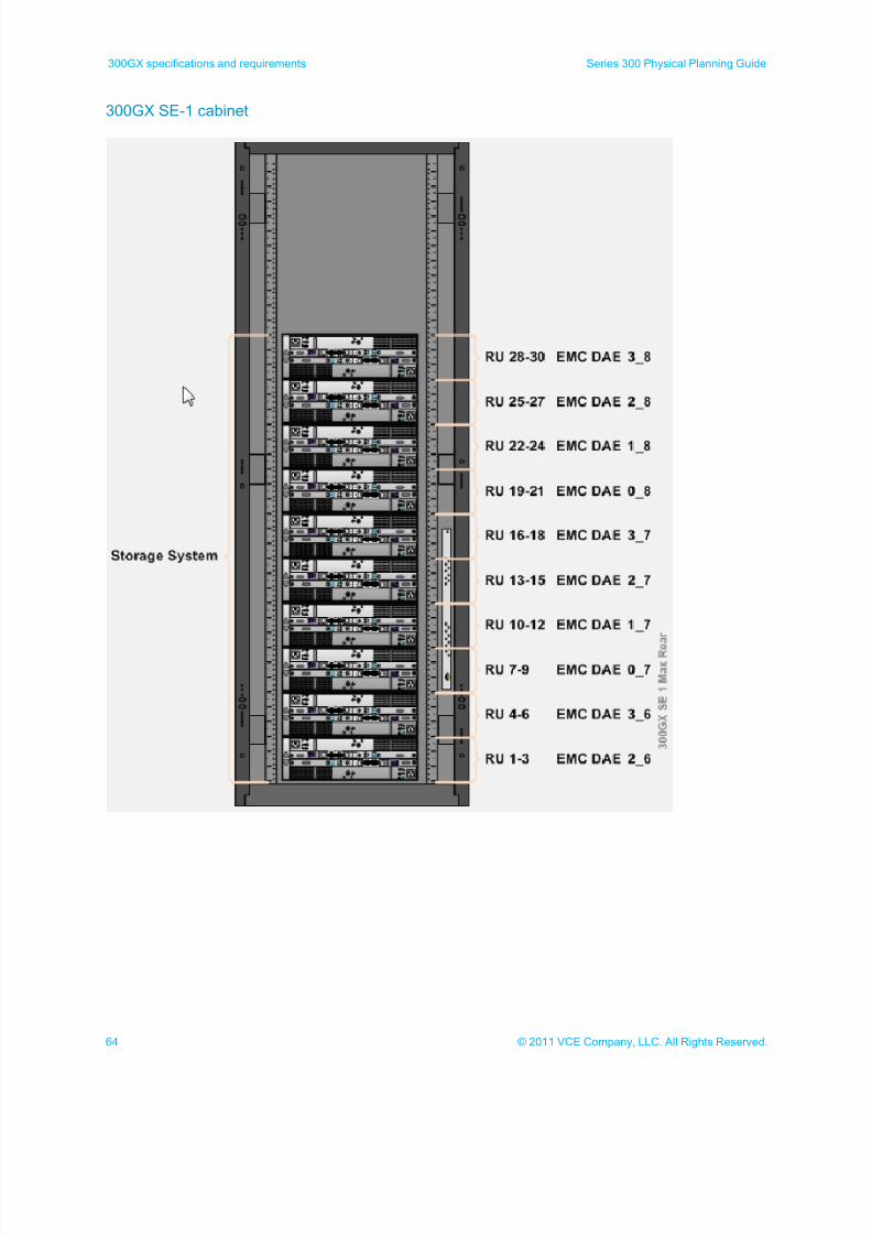
300GX SE-1 cabinet ...................................................................................................................... 64
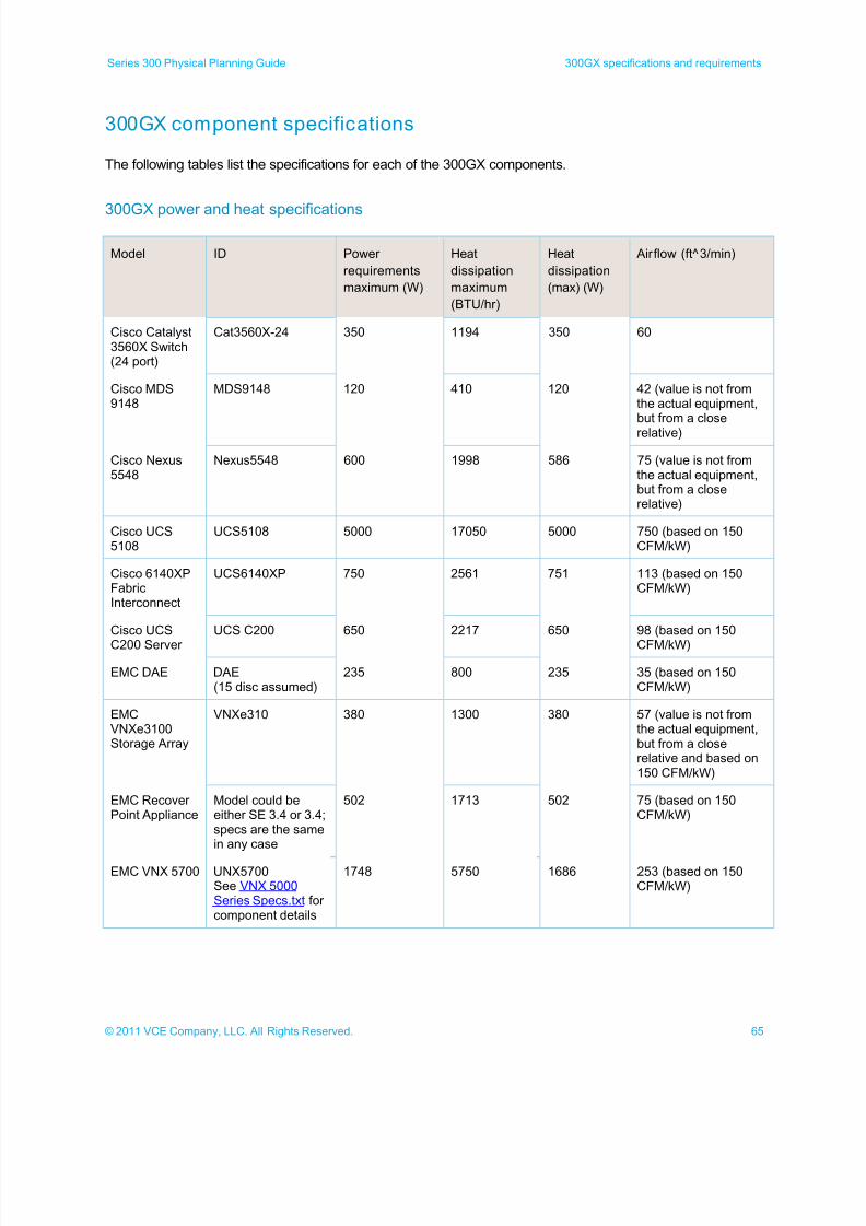
300GX component specifications ......................................................................................................... 65
300GX power and heat specifications ........................................................................................... 65
Cisco Unified Computing System Power Calculator ...................................................................... 66
300GX physical specifications ....................................................................................................... 66
300GX CSB-A maximum thermal and power requirements ................................................................. 67 300GX CSB-B maximum thermal and power requirements ................................................................. 68
300GX CSE-1 maximum thermal and power requirements ................................................................. 69
300GX CSE-2 maximum thermal and power requirements ................................................................. 70
300 SE maximum thermal and power requirements ............................................................................ 71
300GX 60A-3P power calculations ....................................................................................................... 72
300GX 60A-3P CSB-A ................................................................................................................... 73
300GX 60A-3P CSB-B ................................................................................................................... 74
7/21/2019 VCE Vblock™ Systems 300 Physical Planning Guide (Cisco UCS)
http://slidepdf.com/reader/full/vce-vblock-systems-300-physical-planning-guide-cisco-ucs 5/132
5© 2011 VCE Company, LLC. All Rights Reserved.
Series 300 Physical Planning Guide Table of Contents
300GX 60A-3P CSE-1 ................................................................................................................... 75
300GX 60A-3P CSE-2 ................................................................................................................... 76
300GX 60A-3P SE-1 ...................................................................................................................... 77
300GX 32A-3P power calculations ....................................................................................................... 78
300GX 32A-3P CSB-A ................................................................................................................... 79
300GX 32A-3P CSB-B ................................................................................................................... 80 300GX 32A-3P CSE-1 ................................................................................................................... 81
300GX 32A-3P CSE-2 ................................................................................................................... 82
300GX 32A-3P SE-1 ...................................................................................................................... 83
300GX 30A-3P 60A-1P 16A-3P power calculations............................................................................. 84
300GX 30A-3 phase / 60A-1 phase / 16A-3 phase CSB-A positions 1 and 2 ............................... 85
300GX 30A-3 phase / 60A-1 phase / 16A-3 phase CSB-A positions 3 and 4 ............................... 86
300GX 30A-3 phase / 60A-1 phase / 16A-3 phase CSB-B positions 1 and 2 ............................... 87
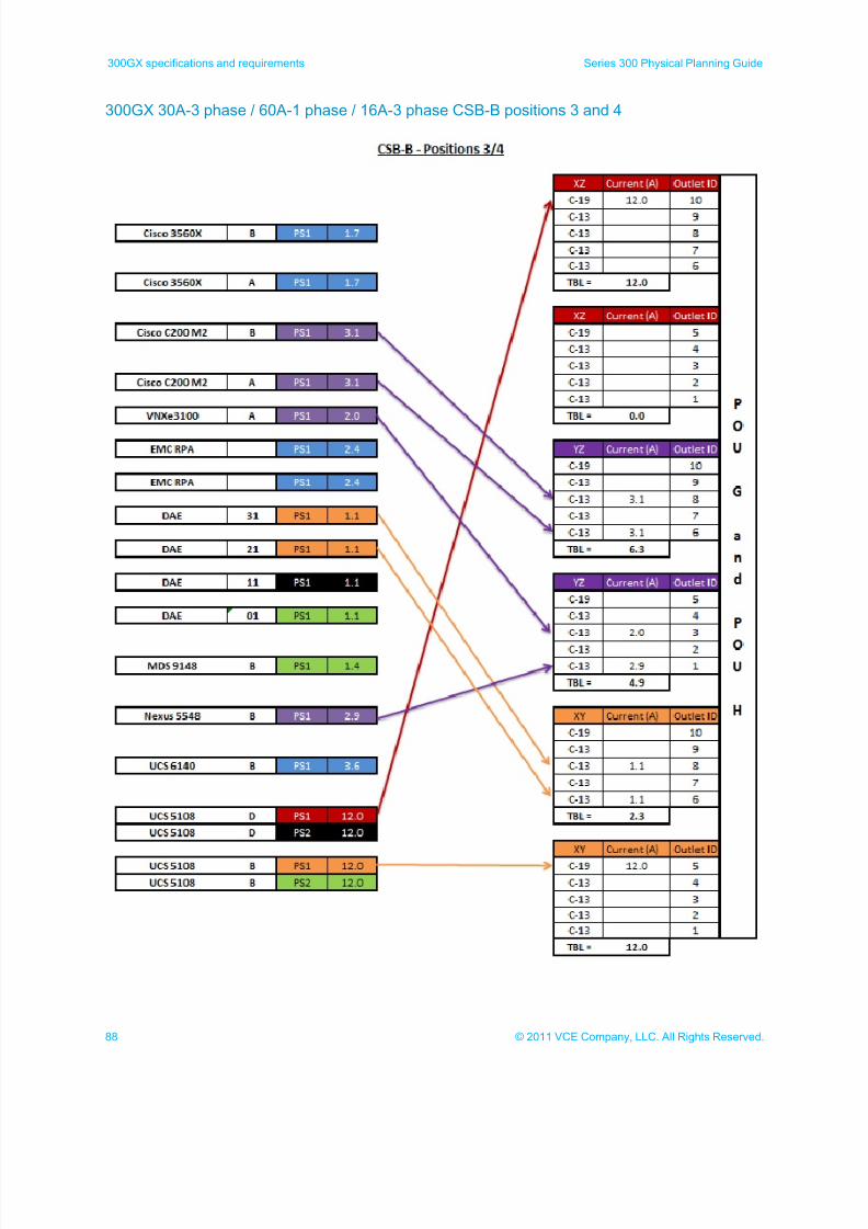
300GX 30A-3 phase / 60A-1 phase / 16A-3 phase CSB-B positions 3 and 4 ............................... 88
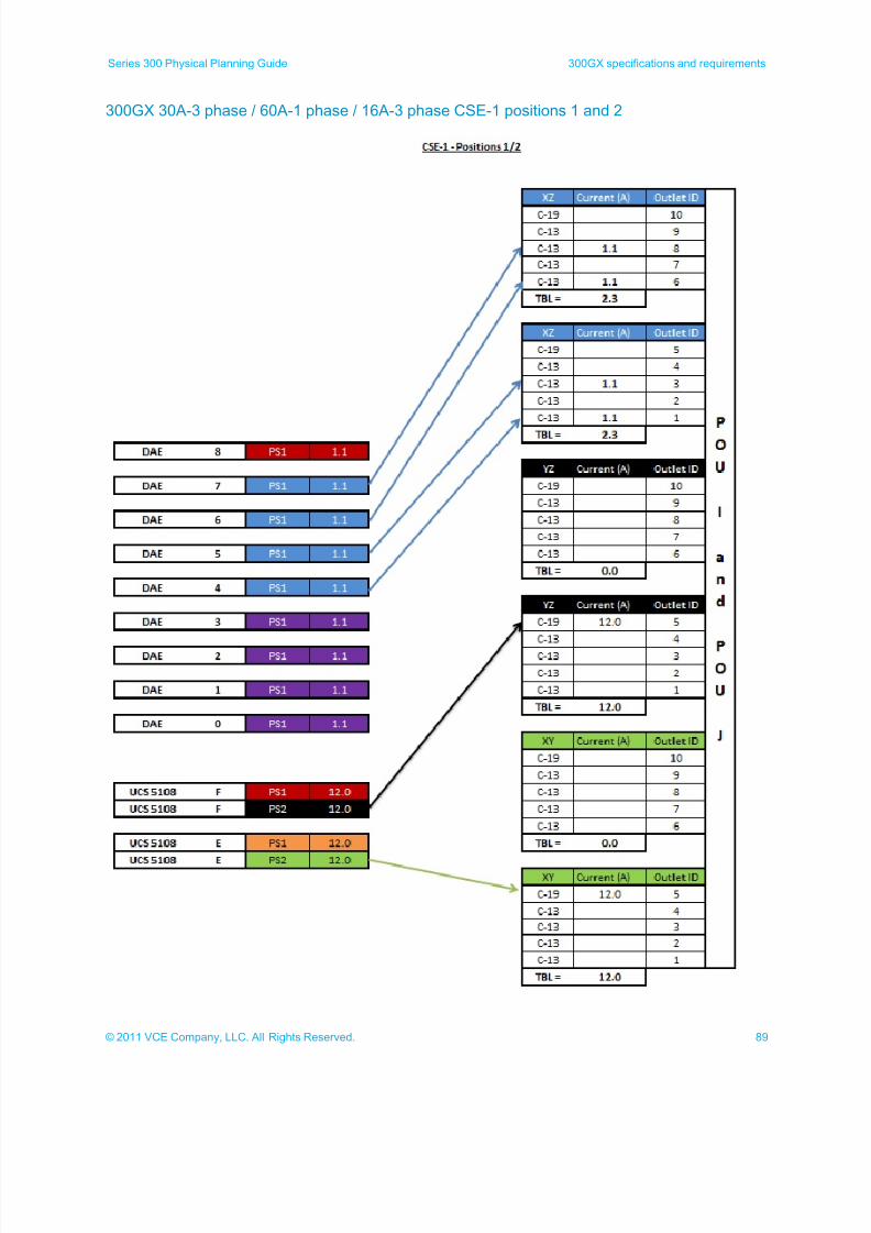
300GX 30A-3 phase / 60A-1 phase / 16A-3 phase CSE-1 positions 1 and 2 ............................... 89
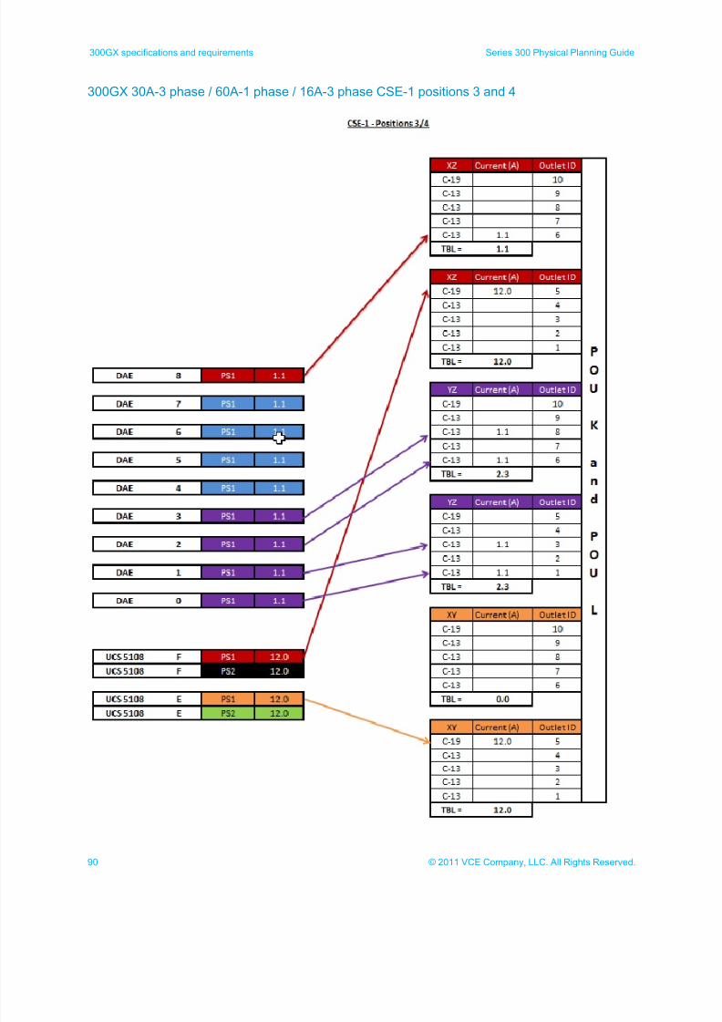
300GX 30A-3 phase / 60A-1 phase / 16A-3 phase CSE-1 positions 3 and 4 ............................... 90
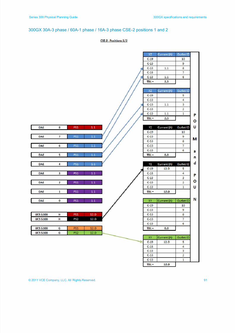
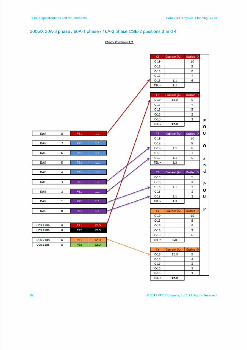
300GX 30A-3 phase / 60A-1 phase / 16A-3 phase CSE-2 positions 1 and 2 ............................... 91 300GX 30A-3 phase / 60A-1 phase / 16A-3 phase CSE-2 positions 3 and 4 ............................... 92
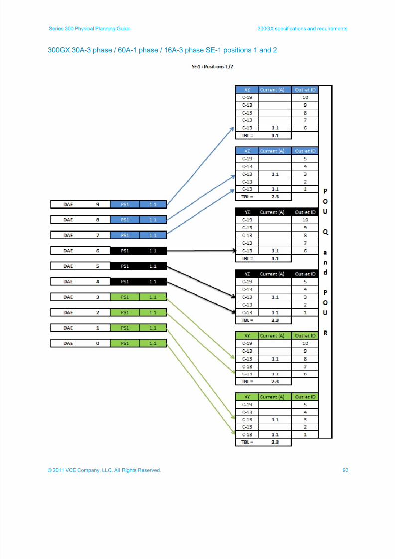
300GX 30A-3 phase / 60A-1 phase / 16A-3 phase SE-1 positions 1 and 2 .................................. 93
300HX specif ications and requ irements ................................................................................................. 94
300HX cabinet layouts .......................................................................................................................... 94
300HX maximum configuration (rear) ............................................................................................ 94
300HX CSB-A cabinet.................................................................................................................... 95
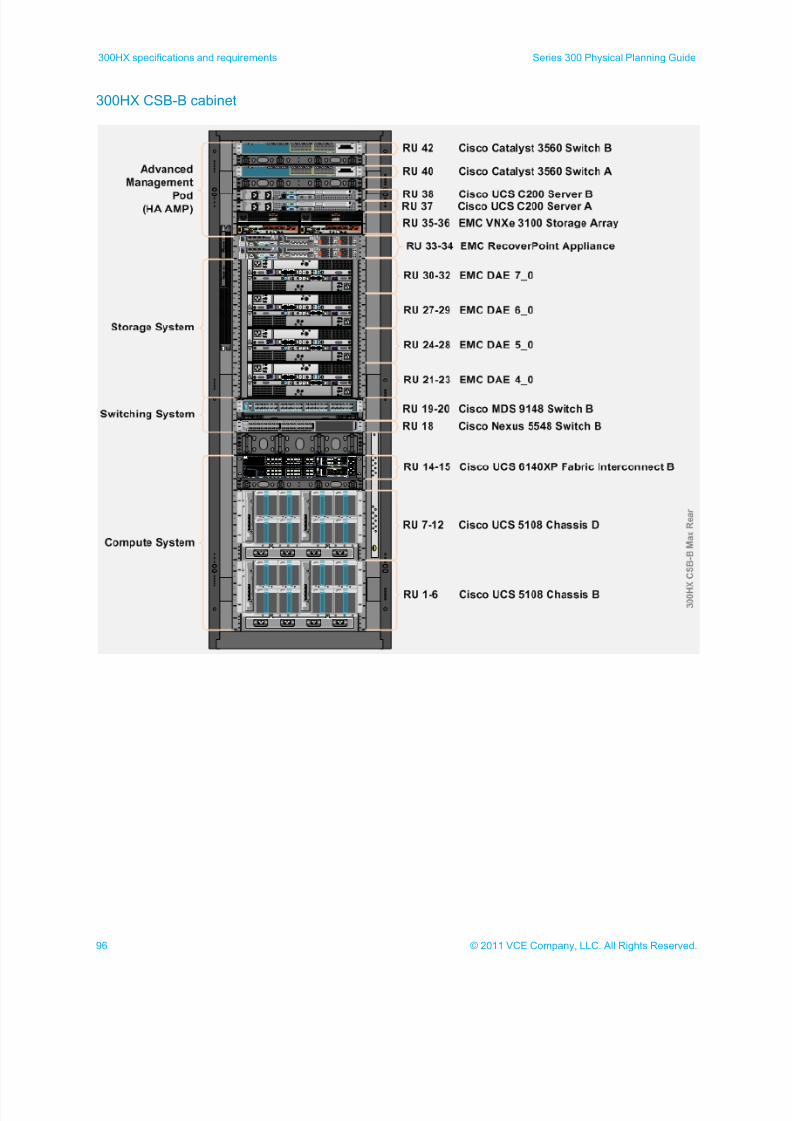
300HX CSB-B cabinet.................................................................................................................... 96
300HX CSE-1 cabinet .................................................................................................................... 97
300HX CSE-2 cabinet .................................................................................................................... 98
300HX SE-1 cabinet ....................................................................................................................... 99 300HX SE-2 cabinet ..................................................................................................................... 100
300HX SE-3 cabinet ..................................................................................................................... 101
300HX SE-4 cabinet ..................................................................................................................... 102
300HX component specifications ....................................................................................................... 103
300HX power and heat specifications .......................................................................................... 103
Cisco Unified Computing System Power Calculator .................................................................... 104
300HX physical specifications ..................................................................................................... 104
300HX CSB-A maximum thermal and power requirements ............................................................... 105
300HX CSB-B maximum thermal and power requirements ............................................................... 106
300HX CSE-1 maximum thermal and power requirements ............................................................... 107
300HX CSE-2 maximum thermal and power requirements ............................................................... 108 300 SE maximum thermal and power requirements .......................................................................... 109
300HX 60A-3P power calculations ..................................................................................................... 110
300HX 60A-3P CSB-A ................................................................................................................. 111
300HX 60A-3P CSB-B ................................................................................................................. 112
300HX 60A-3P CSE-1.................................................................................................................. 113
300HX 60A-3P CSE-2.................................................................................................................. 114
300HX 60A-3P SE-1 through SE-4 .............................................................................................. 115
7/21/2019 VCE Vblock™ Systems 300 Physical Planning Guide (Cisco UCS)
http://slidepdf.com/reader/full/vce-vblock-systems-300-physical-planning-guide-cisco-ucs 6/132
6 © 2011 VCE Company, LLC. All Rights Reserved.
Table of Contents Series 300 Physical Planning Guide
300HX 32A-3P power calculations ..................................................................................................... 116
300HX 32A-3P CSB-A ................................................................................................................. 117
300HX 32A-3P CSB-B ................................................................................................................. 118
300HX 32A-3P CSE-1.................................................................................................................. 119
300HX 32A-3P CSE-2.................................................................................................................. 120
300HX 32A-3P SE-1 through SE-4 .............................................................................................. 121 300HX 30A-3P 60A-1P 16A-3P power calculations ........................................................................... 122
300HX 30A-3 phase / 60A-1 phase / 16A 3 phase positions 1 and 2 ......................................... 123
300HX 30A-3 phase / 60A-1 phase / 16A 3 phase positions 3 and 4 ......................................... 124
300HX 30A-3 phase / 60A-1 phase / 16A 3 phase CSB-B positions 1 and 2 ............................. 125
300HX 30A-3 phase / 60A-1 phase / 16A 3 phase CSB-B positions 3 and 4 ............................. 126
300HX 30A-3 phase / 60A-1 phase / 16A 3 phase CSE-1 positions 1 and 2 .............................. 127
300HX 30A-3 phase / 60A-1 phase / 16A 3 phase CSE-1 positions 3 and 4 .............................. 128
300HX 30A-3 phase / 60A-1 phase / 16A 3 phase CSE-2 positions 1 and 2 .............................. 129
300HX 30A-3 phase / 60A-1 phase / 16A 3 phase CSE-2 positions 3 and 4 .............................. 130
300HX 30A-3 phase / 60A-1 phase / 16A 3 phase SE-1 through SE-4 positions 1 and 2 .......... 131
7/21/2019 VCE Vblock™ Systems 300 Physical Planning Guide (Cisco UCS)
http://slidepdf.com/reader/full/vce-vblock-systems-300-physical-planning-guide-cisco-ucs 7/132
7© 2011 VCE Company, LLC. All Rights Reserved.
Series 300 Physical Planning Guide Introduction
Introduction
This Vblock™ Infrastructure Platforms Series 300 Physical Planning Guide includes the information required to
plan for installing a Vblock Platform at a customer site. The guide is designed to be used by VCE field
personnel and partners while assisting customers in planning their data center requirements for a Vblock
Series 300 Infrastructure Platform. Use this document in conjunction with the Site Survey document todetermine any modifications that may be required in the customer’s data center.
The product data provided in this document is for reference only. For the most current product
specifications, refer to the manufacturer’s documentation.
Refer to the VCE Glossary for additional information.
To suggest documentation changes and provide feedback on this book, send an email to
[email protected]. Include the name of this book, the topic name where your comment applies and your
feedback.
7/21/2019 VCE Vblock™ Systems 300 Physical Planning Guide (Cisco UCS)
http://slidepdf.com/reader/full/vce-vblock-systems-300-physical-planning-guide-cisco-ucs 8/132
8 © 2011 VCE Company, LLC. All Rights Reserved.
Cisco and EMC reference documentation Series 300 Physical Planning Guide
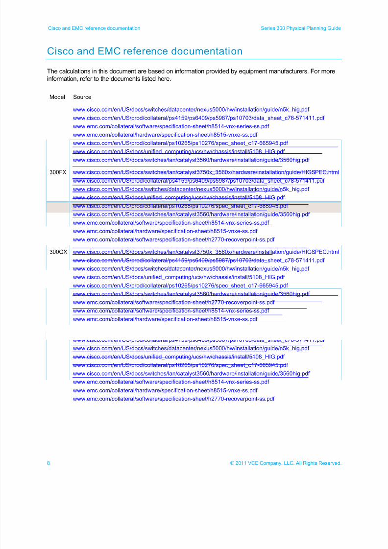
Cisco and EMC reference documentation
The calculations in this document are based on information provided by equipment manufacturers. For more
information, refer to the documents listed here.
Model Source
300EX www.cisco.com/en/US/docs/switches/datacenter/nexus5000/hw/installation/guide/n5k_hig.pdf
www.cisco.com/en/US/prod/collateral/ps4159/ps6409/ps5987/ps10703/data_sheet_c78-571411.pdf
www.emc.com/collateral/software/specification-sheet/h8514-vnx-series-ss.pdf
www.emc.com/collateral/hardware/specification-sheet/h8515-vnxe-ss.pdf
www.cisco.com/en/US/prod/collateral/ps10265/ps10276/spec_sheet_c17-665945.pdf
www.cisco.com/en/US/docs/unified_computing/ucs/hw/chassis/install/5108_HIG.pdf
www.cisco.com/en/US/docs/switches/lan/catalyst3560/hardware/installation/guide/3560hig.pdf
300FX www.cisco.com/en/US/docs/switches/lan/catalyst3750x_3560x/hardware/installation/guide/HIGSPEC.html
www.cisco.com/en/US/prod/collateral/ps4159/ps6409/ps5987/ps10703/data_sheet_c78-571411.pdf
www.cisco.com/en/US/docs/switches/datacenter/nexus5000/hw/installation/guide/n5k_hig.pdf
www.cisco.com/en/US/docs/unified_computing/ucs/hw/chassis/install/5108_HIG.pdf
www.cisco.com/en/US/prod/collateral/ps10265/ps10276/spec_sheet_c17-665945.pdf
www.cisco.com/en/US/docs/switches/lan/catalyst3560/hardware/installation/guide/3560hig.pdf
www.emc.com/collateral/software/specification-sheet/h8514-vnx-series-ss.pdf
www.emc.com/collateral/hardware/specification-sheet/h8515-vnxe-ss.pdf
www.emc.com/collateral/software/specification-sheet/h2770-recoverpoint-ss.pdf
300GX www.cisco.com/en/US/docs/switches/lan/catalyst3750x_3560x/hardware/installation/guide/HIGSPEC.html
www.cisco.com/en/US/prod/collateral/ps4159/ps6409/ps5987/ps10703/data_sheet_c78-571411.pdf
www.cisco.com/en/US/docs/switches/datacenter/nexus5000/hw/installation/guide/n5k_hig.pdf
www.cisco.com/en/US/docs/unified_computing/ucs/hw/chassis/install/5108_HIG.pdf
www.cisco.com/en/US/prod/collateral/ps10265/ps10276/spec_sheet_c17-665945.pdf www.cisco.com/en/US/docs/switches/lan/catalyst3560/hardware/installation/guide/3560hig.pdf
www.emc.com/collateral/software/specification-sheet/h2770-recoverpoint-ss.pdf
www.emc.com/collateral/software/specification-sheet/h8514-vnx-series-ss.pdf
www.emc.com/collateral/hardware/specification-sheet/h8515-vnxe-ss.pdf
300HX www.cisco.com/en/US/docs/switches/lan/catalyst3750x_3560x/hardware/installation/guide/HIGSPEC.html
www.cisco.com/en/US/prod/collateral/ps4159/ps6409/ps5987/ps10703/data_sheet_c78-571411.pdf
www.cisco.com/en/US/docs/switches/datacenter/nexus5000/hw/installation/guide/n5k_hig.pdf
www.cisco.com/en/US/docs/unified_computing/ucs/hw/chassis/install/5108_HIG.pdf
www.cisco.com/en/US/prod/collateral/ps10265/ps10276/spec_sheet_c17-665945.pdf
www.cisco.com/en/US/docs/switches/lan/catalyst3560/hardware/installation/guide/3560hig.pdf
www.emc.com/collateral/software/specification-sheet/h8514-vnx-series-ss.pdf www.emc.com/collateral/hardware/specification-sheet/h8515-vnxe-ss.pdf
www.emc.com/collateral/software/specification-sheet/h2770-recoverpoint-ss.pdf
7/21/2019 VCE Vblock™ Systems 300 Physical Planning Guide (Cisco UCS)
http://slidepdf.com/reader/full/vce-vblock-systems-300-physical-planning-guide-cisco-ucs 9/132
9© 2011 VCE Company, LLC. All Rights Reserved.
Series 300 Physical Planning Guide Panduit reference documentation
Panduit reference documentation
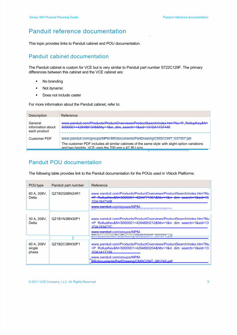
This topic provides links to Panduit cabinet and POU documentation.
Panduit cabinet documentationThe Panduit cabinet is custom for VCE but is very similar to Panduit part number S722C129F. The primary
differences between this cabinet and the VCE cabinet are:
No branding
Not dynamic
Does not include caster
For more information about the Panduit cabinet, refer to:
Description Reference
Generalinformation abouteach product
www.panduit.com/Products/ProductOverviews/ProductSearch/index.htm?Nu=P_RollupKey&N=5000001+4294891348&Nty=1&in_dim_search=1&sid=131DA1737446
Customer PDF www.panduit.com/groups/MPM-BR/documents/PartDrawing/CMSCONT_037357.pdf
The customer PDF includes all similar cabinets of the same style with slight option variationsand two heights. VCE uses the 700 mm x 42 RU size.
Panduit POU documentation
The following table provides link to the Panduit documentation for the POUs used in Vblock Platforms:
POU type Panduit part number Reference
60 A, 208V,Delta
QZ1B2G6BN24R1 www.panduit.com/Products/ProductOverviews/ProductSearch/index.htm?Nu=P_RollupKey&N=5000001+4294771961&Nty=1&in_dim_search=1&sid=131DA184734B
www.panduit.com/groups/MPM-BR/documents/PartDrawing/CMSCONT_081067.pdf
30 A, 208V,Delta
QZ1B1N3BN30P1 www.panduit.com/Products/ProductOverviews/ProductSearch/index.htm?Nu=P_RollupKey&N=5000001+4294893212&Nty=1&in_dim_search=1&sid=131DA193477C
www.panduit.com/groups/MPM-
BR/documents/PartDrawing/CMSCONT_081071.pdf
60 A, 208Vsinglephase
QZ1B2C3BN30P1 www.panduit.com/Products/ProductOverviews/ProductSearch/index.htm?Nu=P_RollupKey&N=5000001+4294893204&Nty=1&in_dim_search=1&sid=131DA1A17156
www.panduit.com/groups/MPM-BR/documents/PartDrawing/CMSCONT_081743.pdf
7/21/2019 VCE Vblock™ Systems 300 Physical Planning Guide (Cisco UCS)
http://slidepdf.com/reader/full/vce-vblock-systems-300-physical-planning-guide-cisco-ucs 10/132
10 © 2011 VCE Company, LLC. All Rights Reserved.
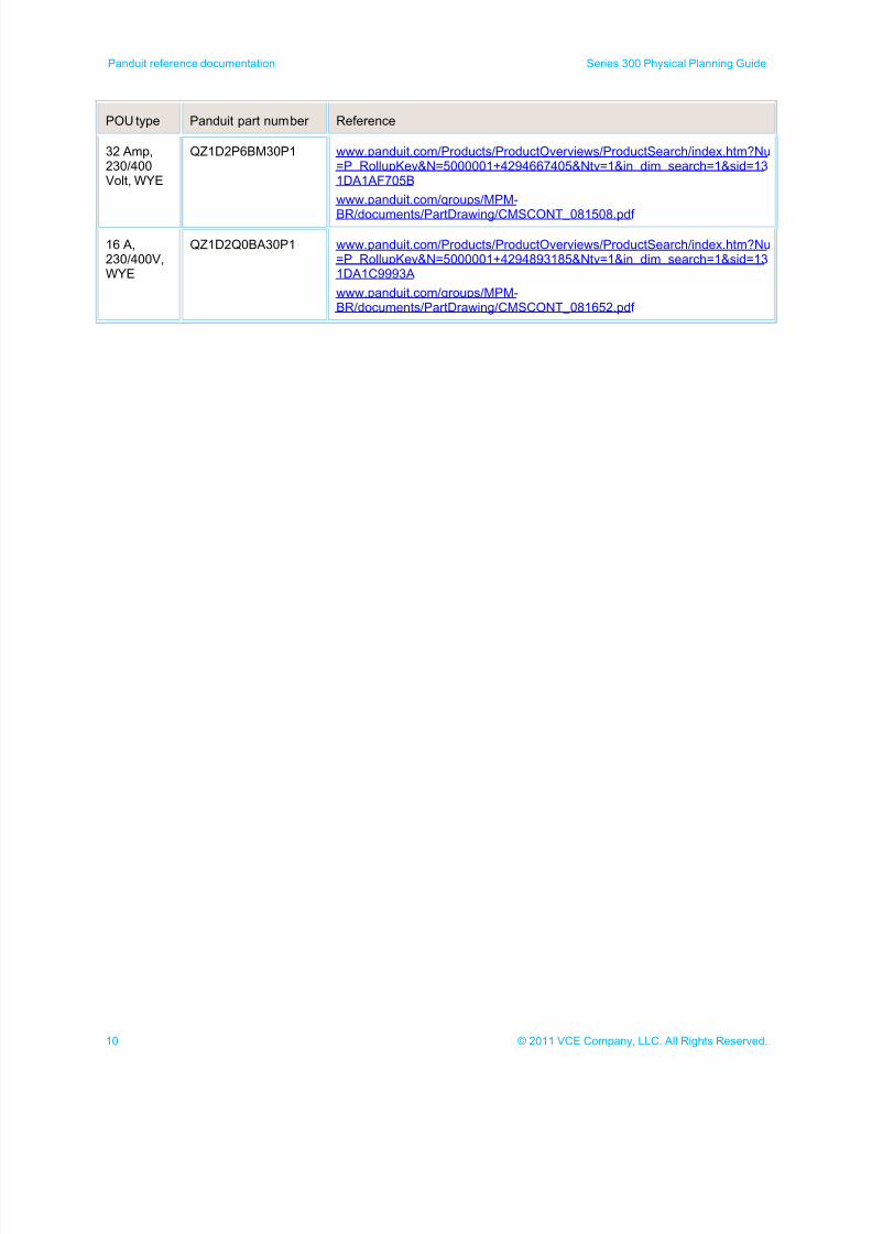
Panduit reference documentation Series 300 Physical Planning Guide
POU type Panduit part number Reference
32 Amp,230/400Volt, WYE
QZ1D2P6BM30P1 www.panduit.com/Products/ProductOverviews/ProductSearch/index.htm?Nu=P_RollupKey&N=5000001+4294667405&Nty=1&in_dim_search=1&sid=131DA1AF705B
www.panduit.com/groups/MPM-
BR/documents/PartDrawing/CMSCONT_081508.pdf
16 A,230/400V,WYE
QZ1D2Q0BA30P1 www.panduit.com/Products/ProductOverviews/ProductSearch/index.htm?Nu=P_RollupKey&N=5000001+4294893185&Nty=1&in_dim_search=1&sid=131DA1C9993A
www.panduit.com/groups/MPM-BR/documents/PartDrawing/CMSCONT_081652.pdf
7/21/2019 VCE Vblock™ Systems 300 Physical Planning Guide (Cisco UCS)
http://slidepdf.com/reader/full/vce-vblock-systems-300-physical-planning-guide-cisco-ucs 11/132
11© 2011 VCE Company, LLC. All Rights Reserved.
Series 300 Physical Planning Guide Physical specifications and requirements
Physical specifications and requirements
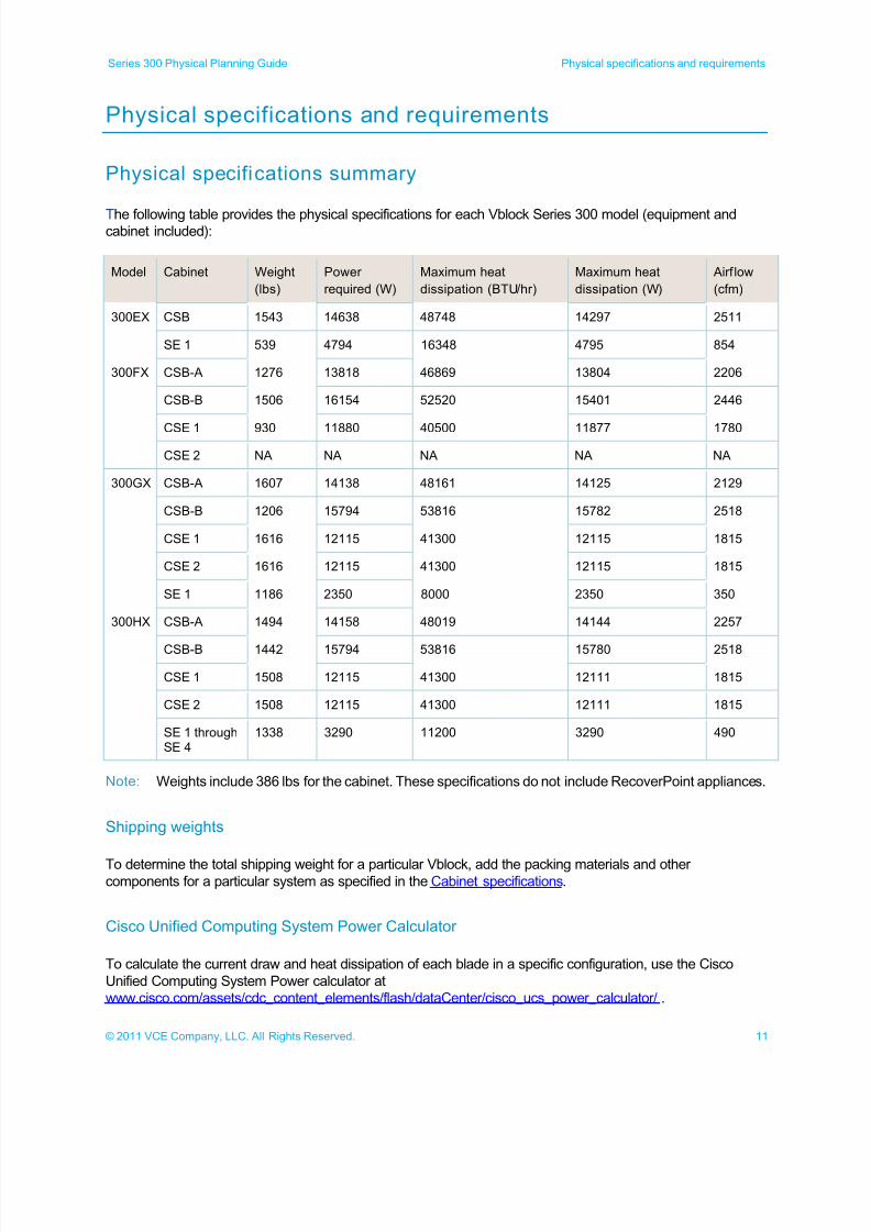
Physical specifications summary
The following table provides the physical specifications for each Vblock Series 300 model (equipment andcabinet included):
Model Cabinet Weight
(lbs)
Power
required (W)
Maximum heat
dissipation (BTU/hr)
Maximum heat
dissipation (W)
Airf low
(cfm)
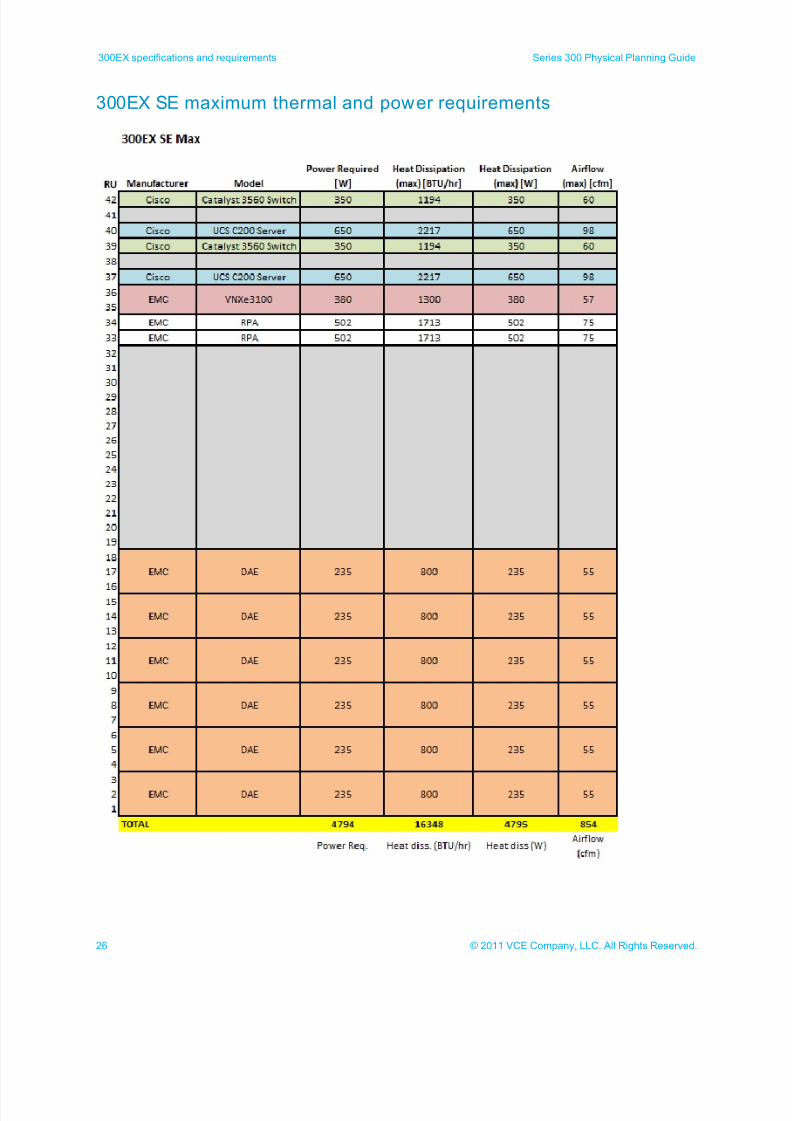
300EX CSB 1543 14638 48748 14297 2511
SE 1 539 4794 16348 4795 854
300FX CSB-A 1276 13818 46869 13804 2206
CSB-B 1506 16154 52520 15401 2446
CSE 1 930 11880 40500 11877 1780
CSE 2 NA NA NA NA NA
300GX CSB-A 1607 14138 48161 14125 2129
CSB-B 1206 15794 53816 15782 2518
CSE 1 1616 12115 41300 12115 1815
CSE 2 1616 12115 41300 12115 1815
SE 1 1186 2350 8000 2350 350
300HX CSB-A 1494 14158 48019 14144 2257
CSB-B 1442 15794 53816 15780 2518
CSE 1 1508 12115 41300 12111 1815
CSE 2 1508 12115 41300 12111 1815
SE 1 throughSE 4
1338 3290 11200 3290 490
Note: Weights include 386 lbs for the cabinet. These specifications do not include RecoverPoint appliances.
Shipping weights
To determine the total shipping weight for a particular Vblock, add the packing materials and othercomponents for a particular system as specified in the Cabinet specifications.
Cisco Unified Computing System Power Calculator
To calculate the current draw and heat dissipation of each blade in a specific configuration, use the Cisco
Unified Computing System Power calculator at
www.cisco.com/assets/cdc_content_elements/flash/dataCenter/cisco_ucs_power_calculator/ .
7/21/2019 VCE Vblock™ Systems 300 Physical Planning Guide (Cisco UCS)
http://slidepdf.com/reader/full/vce-vblock-systems-300-physical-planning-guide-cisco-ucs 12/132
12 © 2011 VCE Company, LLC. All Rights Reserved.
Physical specifications and requirements Series 300 Physical Planning Guide
Blade power consumption
For information about calculating blade power consumption, refer to the Vblock™ Infrastructure Platforms
Blade Packs Reference.
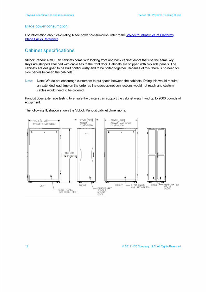
Cabinet specifications
Vblock Panduit NetSERV cabinets come with locking front and back cabinet doors that use the same key.
Keys are shipped attached with cable ties to the front door. Cabinets are shipped with two side panels. The
cabinets are designed to be built contiguously and to be bolted together. Because of this, there is no need for
side panels between the cabinets.
Note: Note: We do not encourage customers to put space between the cabinets. Doing this would require
an extended lead time on the order as the cross-abinet connections would not reach and custom
cables would need to be ordered.
Panduit does extensive testing to ensure the casters can support the cabinet weight and up to 2000 pounds of
equipment.
The following illustration shows the Vblock Panduit cabinet dimensions:
7/21/2019 VCE Vblock™ Systems 300 Physical Planning Guide (Cisco UCS)
http://slidepdf.com/reader/full/vce-vblock-systems-300-physical-planning-guide-cisco-ucs 13/132
13© 2011 VCE Company, LLC. All Rights Reserved.
Series 300 Physical Planning Guide Physical specifications and requirements
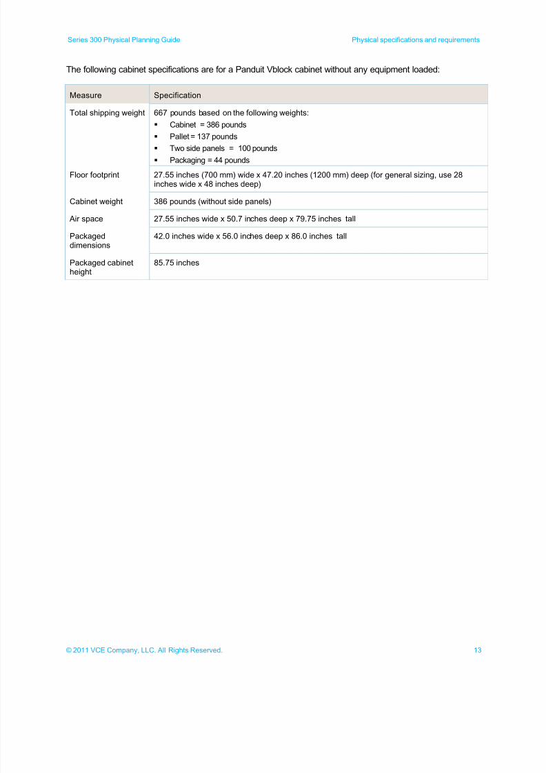
The following cabinet specifications are for a Panduit Vblock cabinet without any equipment loaded:
Measure Specification
Total shipping weight 667 pounds based on the following weights:
Cabinet = 386 pounds
Pallet = 137 pounds
Two side panels = 100 pounds
Packaging = 44 pounds
Floor footprint 27.55 inches (700 mm) wide x 47.20 inches (1200 mm) deep (for general sizing, use 28inches wide x 48 inches deep)
Cabinet weight 386 pounds (without side panels)
Air space 27.55 inches wide x 50.7 inches deep x 79.75 inches tall
Packageddimensions
42.0 inches wide x 56.0 inches deep x 86.0 inches tall
Packaged cabinet
height
85.75 inches
7/21/2019 VCE Vblock™ Systems 300 Physical Planning Guide (Cisco UCS)
http://slidepdf.com/reader/full/vce-vblock-systems-300-physical-planning-guide-cisco-ucs 14/132
14 © 2011 VCE Company, LLC. All Rights Reserved.
Physical specifications and requirements Series 300 Physical Planning Guide
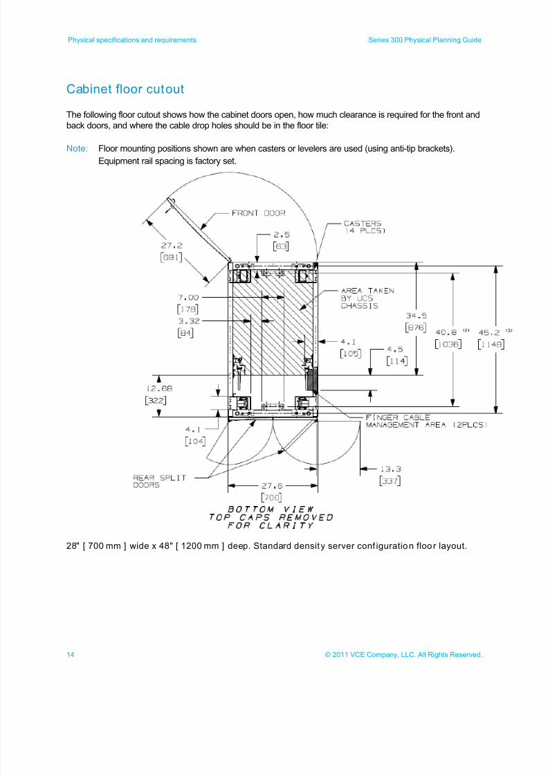
Cabinet floor cutout
The following floor cutout shows how the cabinet doors open, how much clearance is required for the front and
back doors, and where the cable drop holes should be in the floor tile:
Note: Floor mounting positions shown are when casters or levelers are used (using anti-tip brackets).
Equipment rail spacing is factory set.
28" [ 700 mm ] wide x 48" [ 1200 mm ] deep. Standard density server conf iguration floo r layout.
7/21/2019 VCE Vblock™ Systems 300 Physical Planning Guide (Cisco UCS)
http://slidepdf.com/reader/full/vce-vblock-systems-300-physical-planning-guide-cisco-ucs 15/132
15© 2011 VCE Company, LLC. All Rights Reserved.
Series 300 Physical Planning Guide Physical specifications and requirements
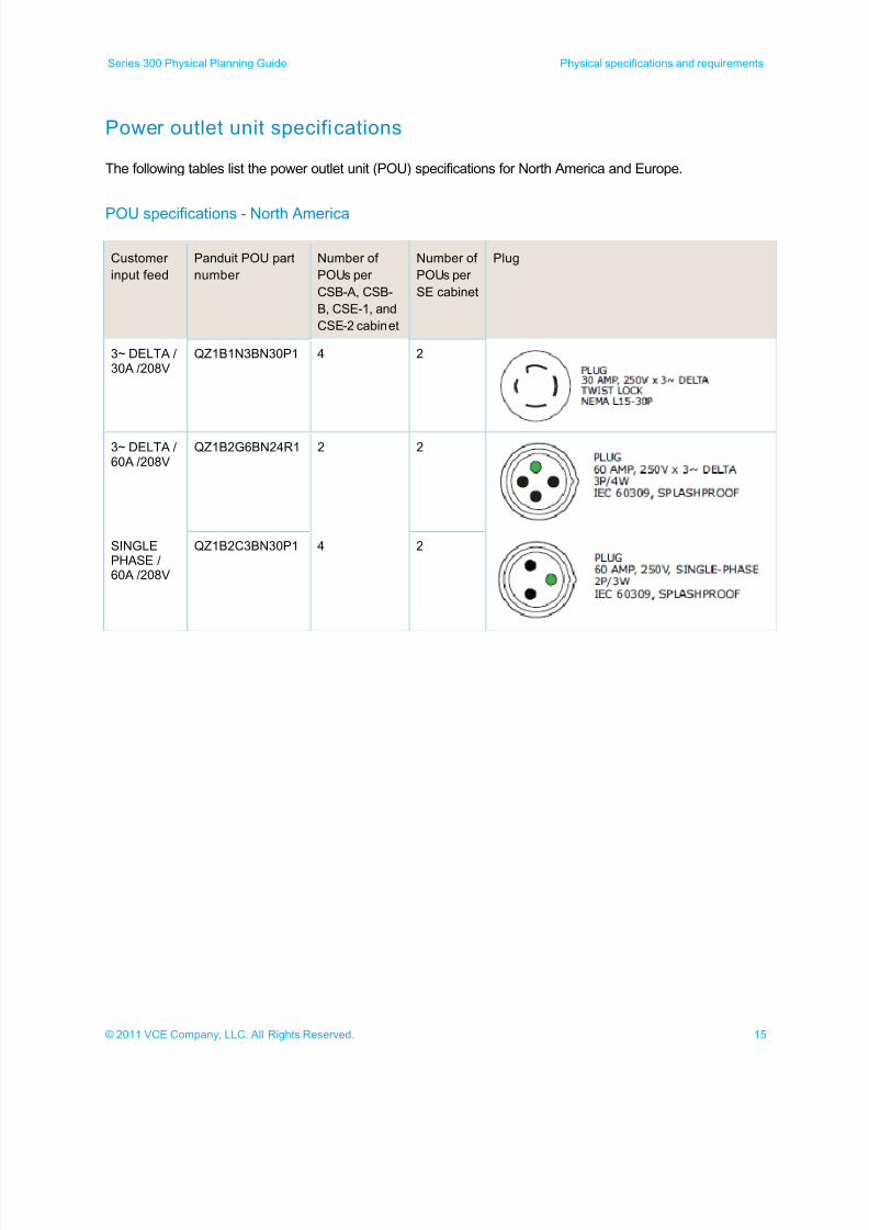
Power outlet unit specifications
The following tables list the power outlet unit (POU) specifications for North America and Europe.
POU specifications - North America
Customer
input feed
Panduit POU part
number
Number of
POUs per
CSB-A, CSB-
B, CSE-1, and
CSE-2 cabinet
Number of
POUs per
SE cabinet
Plug
3~ DELTA /30A /208V
QZ1B1N3BN30P1 4 2
3~ DELTA /60A /208V
QZ1B2G6BN24R1 2 2
SINGLEPHASE /60A /208V
QZ1B2C3BN30P1 4 2
7/21/2019 VCE Vblock™ Systems 300 Physical Planning Guide (Cisco UCS)
http://slidepdf.com/reader/full/vce-vblock-systems-300-physical-planning-guide-cisco-ucs 16/132
16 © 2011 VCE Company, LLC. All Rights Reserved.
Physical specifications and requirements Series 300 Physical Planning Guide
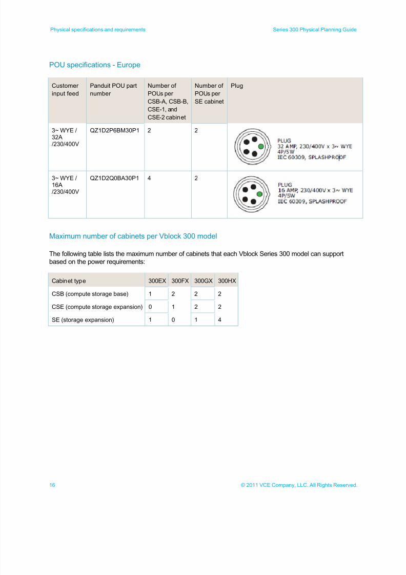
POU specifications - Europe
Customer
input feed
Panduit POU part
number
Number of
POUs per
CSB-A, CSB-B,CSE-1, and
CSE-2 cabinet
Number of
POUs per
SE cabinet
Plug
3~ WYE /32A/230/400V
QZ1D2P6BM30P1 2 2
3~ WYE /16A/230/400V
QZ1D2Q0BA30P1 4 2
Maximum number of cabinets per Vblock 300 model
The following table lists the maximum number of cabinets that each Vblock Series 300 model can support
based on the power requirements:
Cabinet type 300EX 300FX 300GX 300HX
CSB (compute storage base) 1 2 2 2
CSE (compute storage expansion) 0 1 2 2
SE (storage expansion) 1 0 1 4
7/21/2019 VCE Vblock™ Systems 300 Physical Planning Guide (Cisco UCS)
http://slidepdf.com/reader/full/vce-vblock-systems-300-physical-planning-guide-cisco-ucs 17/132
17© 2011 VCE Company, LLC. All Rights Reserved.
Series 300 Physical Planning Guide Physical specifications and requirements
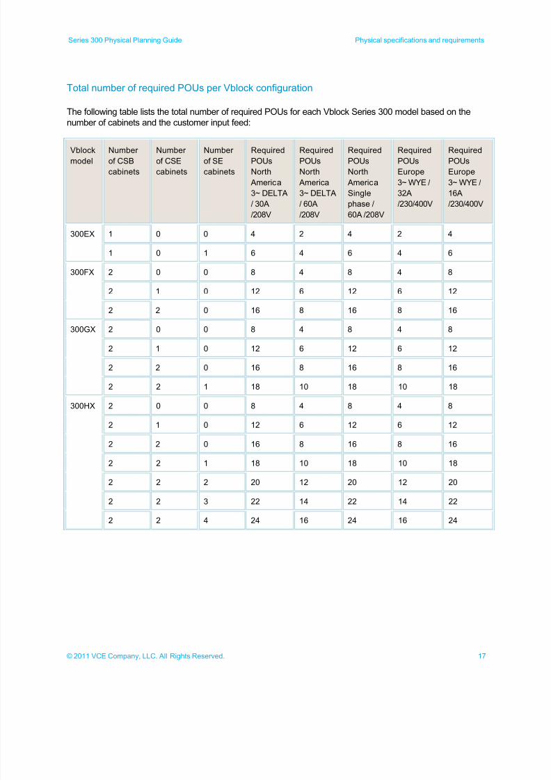
Total number of required POUs per Vblock configuration
The following table lists the total number of required POUs for each Vblock Series 300 model based on the
number of cabinets and the customer input feed:
Vblock
model
Number
of CSB
cabinets
Number
of CSE
cabinets
Number
of SE
cabinets
Required
POUs
North
America
3~ DELTA
/ 30A
/208V
Required
POUs
North
America
3~ DELTA
/ 60A
/208V
Required
POUs
North
America
Single
phase /
60A /208V
Required
POUs
Europe
3~ WYE /
32A
/230/400V
Required
POUs
Europe
3~ WYE /
16A
/230/400V
300EX 1 0 0 4 2 4 2 4
1 0 1 6 4 6 4 6
300FX 2 0 0 8 4 8 4 8
2 1 0 12 6 12 6 12
2 2 0 16 8 16 8 16
300GX 2 0 0 8 4 8 4 8
2 1 0 12 6 12 6 12
2 2 0 16 8 16 8 16
2 2 1 18 10 18 10 18
300HX 2 0 0 8 4 8 4 8
2 1 0 12 6 12 6 12
2 2 0 16 8 16 8 16
2 2 1 18 10 18 10 18
2 2 2 20 12 20 12 20
2 2 3 22 14 22 14 22
2 2 4 24 16 24 16 24
7/21/2019 VCE Vblock™ Systems 300 Physical Planning Guide (Cisco UCS)
http://slidepdf.com/reader/full/vce-vblock-systems-300-physical-planning-guide-cisco-ucs 18/132
18 © 2011 VCE Company, LLC. All Rights Reserved.
Physical specifications and requirements Series 300 Physical Planning Guide
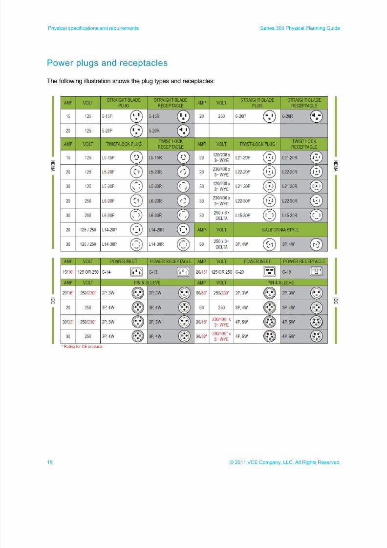
Power plugs and receptacles
The following illustration shows the plug types and receptacles:
7/21/2019 VCE Vblock™ Systems 300 Physical Planning Guide (Cisco UCS)
http://slidepdf.com/reader/full/vce-vblock-systems-300-physical-planning-guide-cisco-ucs 19/132
19© 2011 VCE Company, LLC. All Rights Reserved.
Series 300 Physical Planning Guide 300EX specifications and requirements
300EX specifications and requirements
300EX cabinet layouts
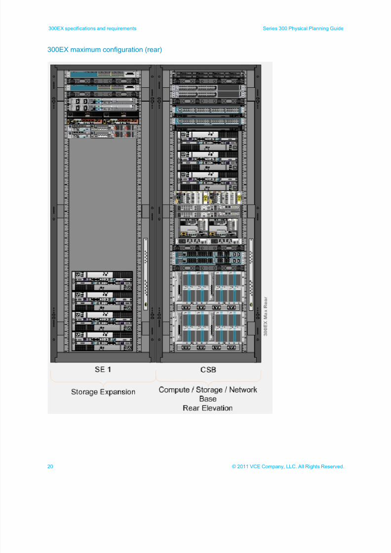
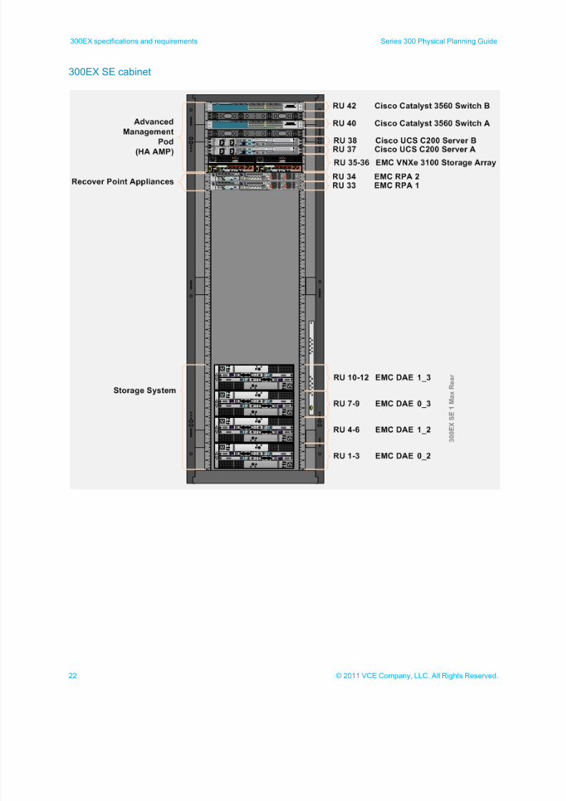
The 300EX can include up to two cabinets: CSB cabinet and SE cabinet. The AMP can be installed in eitheran SE cabinet or in a customer provided cabinet. The following illustrations show the maximum configuration
options for the 300EX.
7/21/2019 VCE Vblock™ Systems 300 Physical Planning Guide (Cisco UCS)
http://slidepdf.com/reader/full/vce-vblock-systems-300-physical-planning-guide-cisco-ucs 20/132
20 © 2011 VCE Company, LLC. All Rights Reserved.
300EX specifications and requirements Series 300 Physical Planning Guide
300EX maximum configuration (rear)
7/21/2019 VCE Vblock™ Systems 300 Physical Planning Guide (Cisco UCS)
http://slidepdf.com/reader/full/vce-vblock-systems-300-physical-planning-guide-cisco-ucs 21/132
21© 2011 VCE Company, LLC. All Rights Reserved.
Series 300 Physical Planning Guide 300EX specifications and requirements
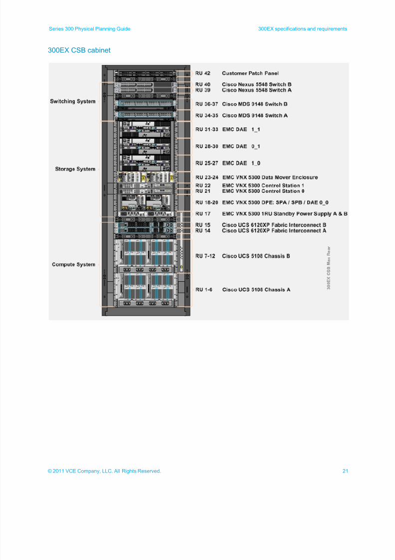
300EX CSB cabinet
7/21/2019 VCE Vblock™ Systems 300 Physical Planning Guide (Cisco UCS)
http://slidepdf.com/reader/full/vce-vblock-systems-300-physical-planning-guide-cisco-ucs 22/132
22 © 2011 VCE Company, LLC. All Rights Reserved.
300EX specifications and requirements Series 300 Physical Planning Guide
300EX SE cabinet
7/21/2019 VCE Vblock™ Systems 300 Physical Planning Guide (Cisco UCS)
http://slidepdf.com/reader/full/vce-vblock-systems-300-physical-planning-guide-cisco-ucs 23/132
23© 2011 VCE Company, LLC. All Rights Reserved.
Series 300 Physical Planning Guide 300EX specifications and requirements
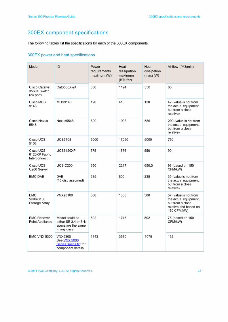
300EX component specifications
The following tables list the specifications for each of the 300EX components.
300EX power and heat specifications
Model ID Power
requirements
maximum (W)
Heat
dissipation
maximum
(BTU/hr)
Heat
dissipation
(max) (W)
Airflow (ft^3/min)
Cisco Catalyst3560X Switch(24 port)
Cat3560X-24 350 1194 350 60
Cisco MDS9148
MDS9148 120 410 120 42 (value is not fromthe actual equipment,but from a close
relative)
Cisco Nexus5548
Nexus5548 600 1998 586 200 (value is not fromthe actual equipment,but from a closerelative)
Cisco UCS5108
UCS5108 5000 17050 5000 750
Cisco UCS6120XP FabricInterconnect
UCS6120XP 675 1876 550 90
Cisco UCS
C200 Server
UCS C200 650 2217 650.0 98 (based on 150
CFM/kW)
EMC DAE DAE(15 disc assumed)
235 800 235 35 (value is not fromthe actual equipment,but from a closerelative)
EMCVNXe3100Storage Array
VNXe3100 380 1300 380 57 (value is not fromthe actual equipment,but from a closerelative and based on150 CFM/kW)
EMC RecoverPoint Appliance
Model could beeither SE 3.4 or 3.4;
specs are the samein any case
502 1713 502 75 (based on 150CFM/kW)
EMC VNX 5300 VNX5300See VNX 5000Series Specs.txt forcomponent details
1143 3680 1079 162
7/21/2019 VCE Vblock™ Systems 300 Physical Planning Guide (Cisco UCS)
http://slidepdf.com/reader/full/vce-vblock-systems-300-physical-planning-guide-cisco-ucs 24/132
24 © 2011 VCE Company, LLC. All Rights Reserved.
300EX specifications and requirements Series 300 Physical Planning Guide
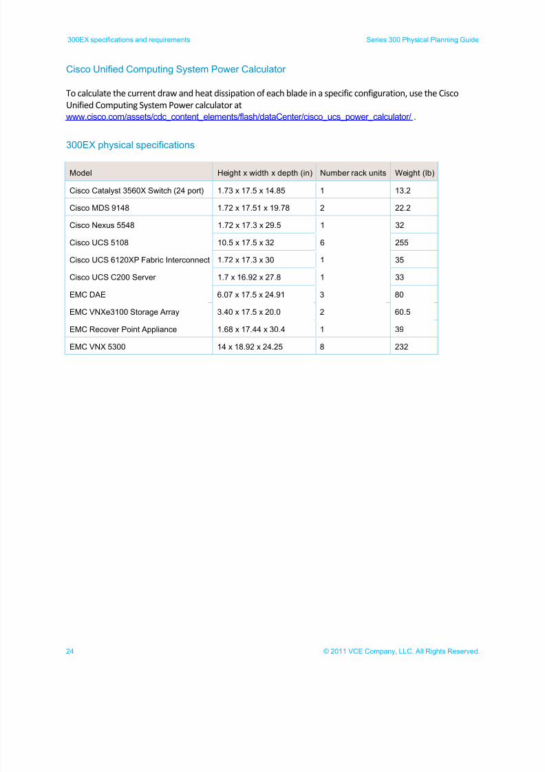
Cisco Unified Computing System Power Calculator
To calculate the current draw and heat dissipation of each blade in a specific configuration, use the Cisco
Unified Computing System Power calculator at
www.cisco.com/assets/cdc_content_elements/flash/dataCenter/cisco_ucs_power_calculator/ .
300EX physical specifications
Model Height x width x depth (in) Number rack units Weight (lb)
Cisco Catalyst 3560X Switch (24 port) 1.73 x 17.5 x 14.85 1 13.2
Cisco MDS 9148 1.72 x 17.51 x 19.78 2 22.2
Cisco Nexus 5548 1.72 x 17.3 x 29.5 1 32
Cisco UCS 5108 10.5 x 17.5 x 32 6 255
Cisco UCS 6120XP Fabric Interconnect 1.72 x 17.3 x 30 1 35
Cisco UCS C200 Server 1.7 x 16.92 x 27.8 1 33
EMC DAE 6.07 x 17.5 x 24.91 3 80
EMC VNXe3100 Storage Array 3.40 x 17.5 x 20.0 2 60.5
EMC Recover Point Appliance 1.68 x 17.44 x 30.4 1 39
EMC VNX 5300 14 x 18.92 x 24.25 8 232
7/21/2019 VCE Vblock™ Systems 300 Physical Planning Guide (Cisco UCS)
http://slidepdf.com/reader/full/vce-vblock-systems-300-physical-planning-guide-cisco-ucs 25/132
25© 2011 VCE Company, LLC. All Rights Reserved.
Series 300 Physical Planning Guide 300EX specifications and requirements
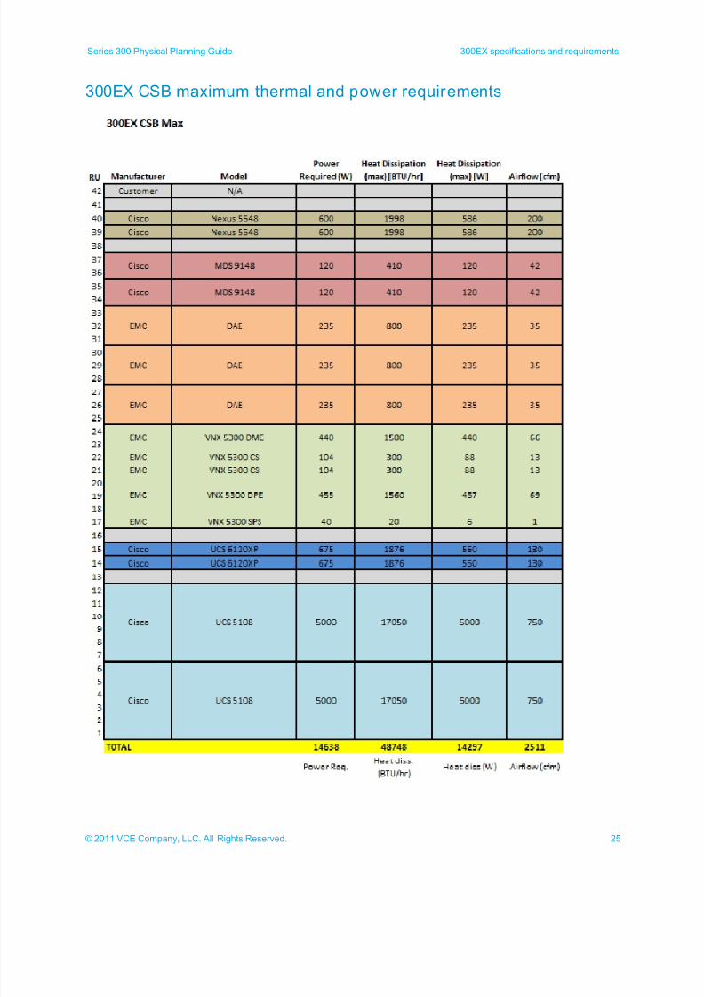
300EX CSB maximum thermal and power requirements
7/21/2019 VCE Vblock™ Systems 300 Physical Planning Guide (Cisco UCS)
http://slidepdf.com/reader/full/vce-vblock-systems-300-physical-planning-guide-cisco-ucs 26/132
26 © 2011 VCE Company, LLC. All Rights Reserved.
300EX specifications and requirements Series 300 Physical Planning Guide
300EX SE maximum thermal and power requirements
7/21/2019 VCE Vblock™ Systems 300 Physical Planning Guide (Cisco UCS)
http://slidepdf.com/reader/full/vce-vblock-systems-300-physical-planning-guide-cisco-ucs 27/132
27© 2011 VCE Company, LLC. All Rights Reserved.
Series 300 Physical Planning Guide 300EX specifications and requirements
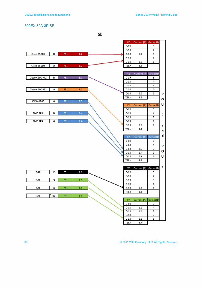
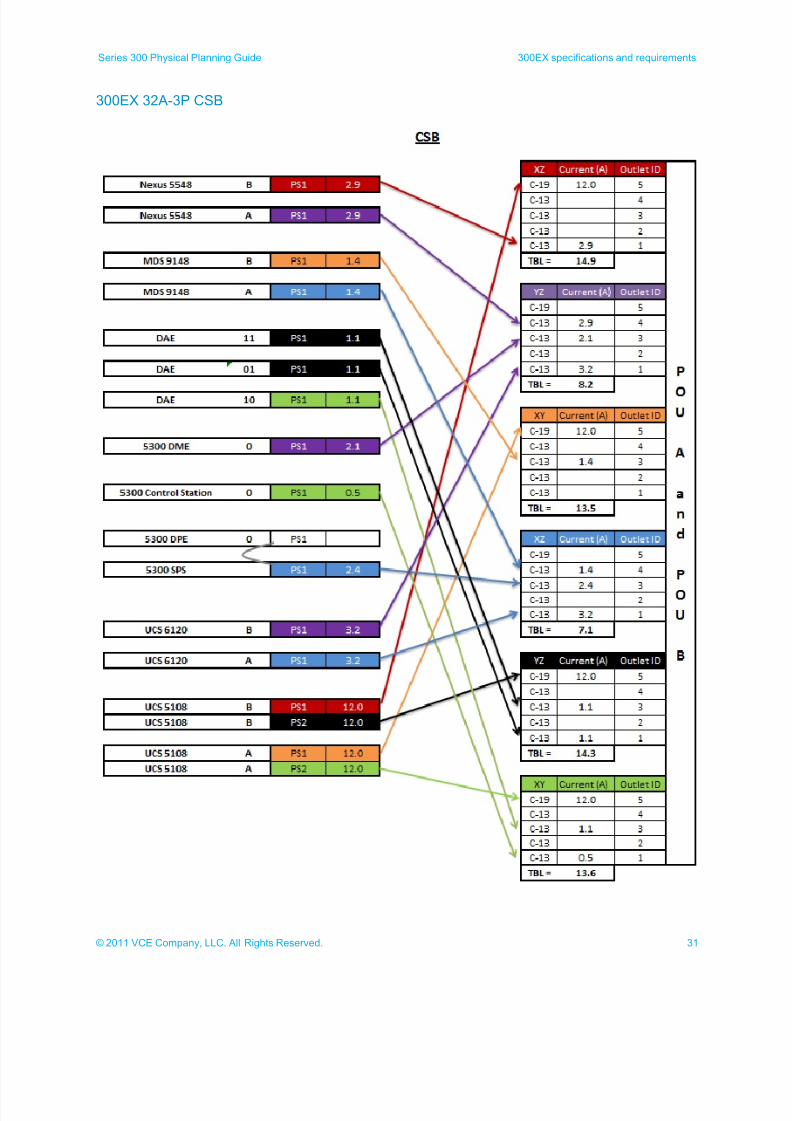
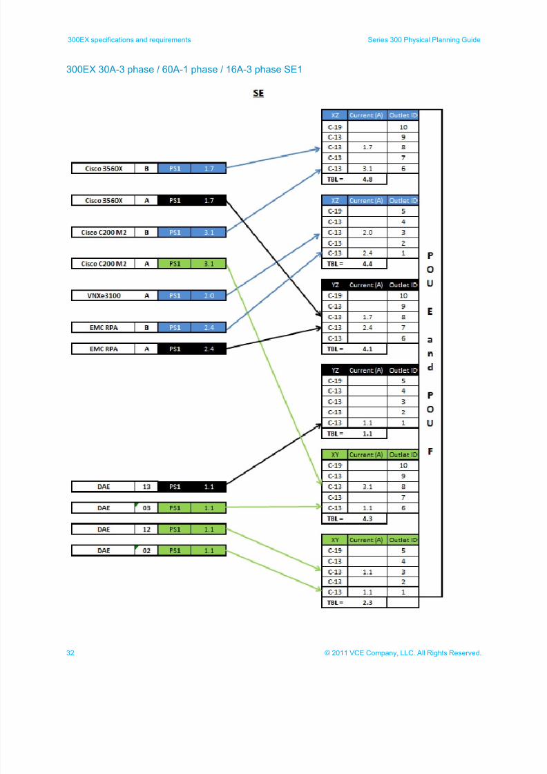
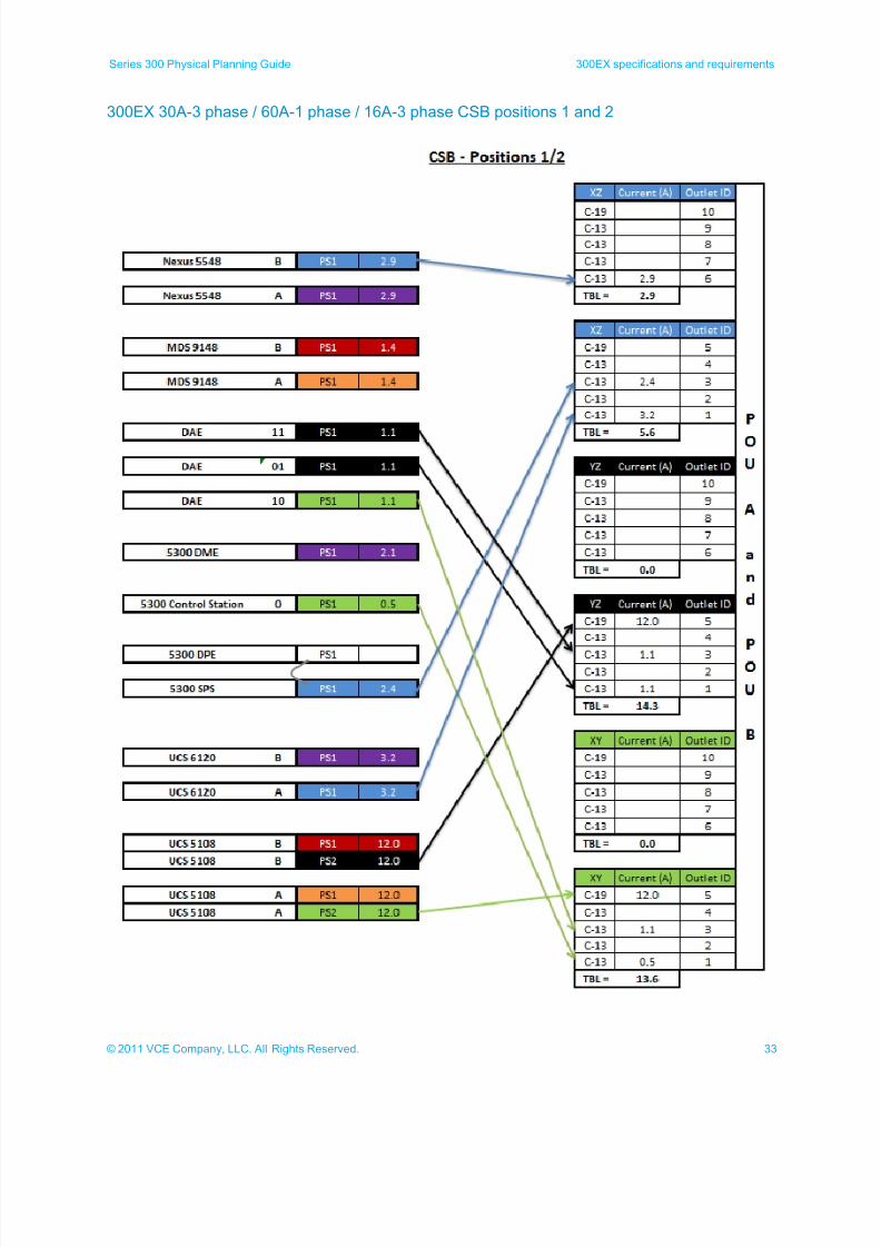
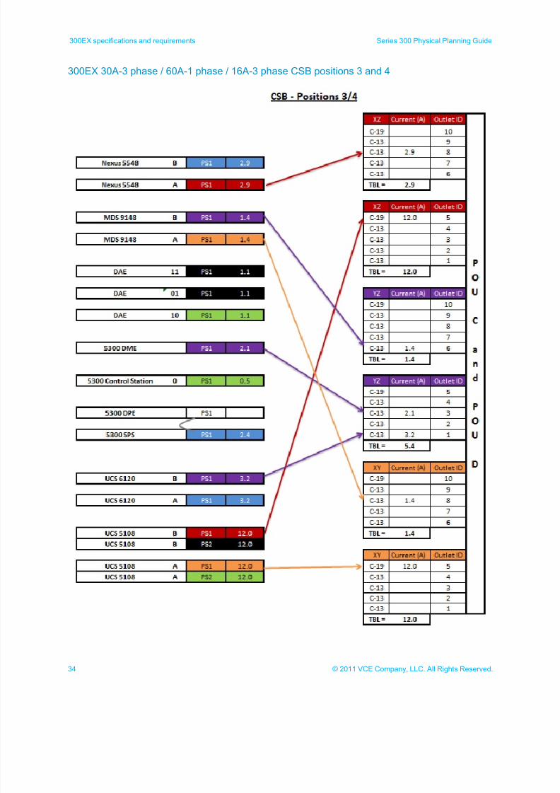
300EX power calculations
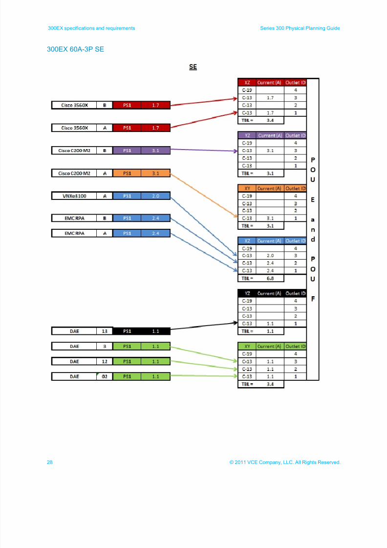
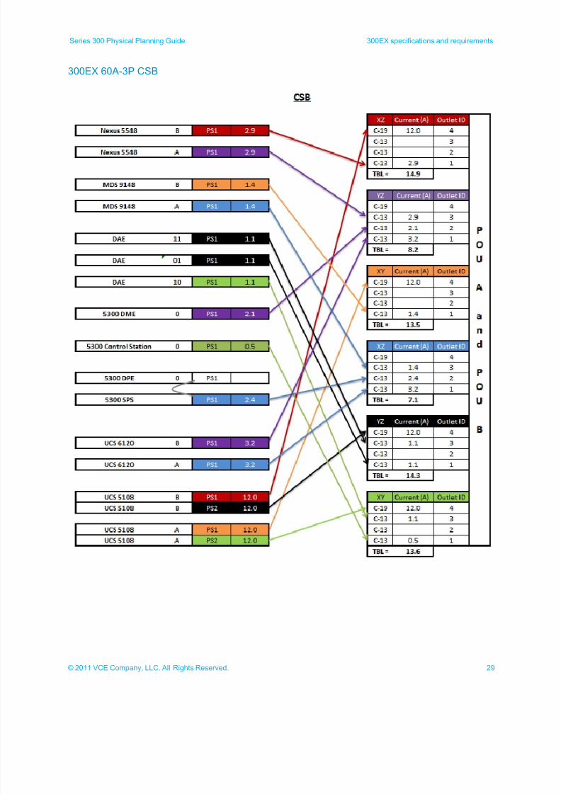
The following illustrations show the power calculations used for determining the maximum power used by
300EX cabinets.
Note: Components marked with a gray line (DAEs and DPEs) plug into the standby power supply (5300
SPS) and are not directly included in the power calculations. The standby power supply is used in
these calculations.
7/21/2019 VCE Vblock™ Systems 300 Physical Planning Guide (Cisco UCS)
http://slidepdf.com/reader/full/vce-vblock-systems-300-physical-planning-guide-cisco-ucs 28/132
28 © 2011 VCE Company, LLC. All Rights Reserved.
300EX specifications and requirements Series 300 Physical Planning Guide
300EX 60A-3P SE
7/21/2019 VCE Vblock™ Systems 300 Physical Planning Guide (Cisco UCS)
http://slidepdf.com/reader/full/vce-vblock-systems-300-physical-planning-guide-cisco-ucs 29/132
29© 2011 VCE Company, LLC. All Rights Reserved.
Series 300 Physical Planning Guide 300EX specifications and requirements
300EX 60A-3P CSB
7/21/2019 VCE Vblock™ Systems 300 Physical Planning Guide (Cisco UCS)
http://slidepdf.com/reader/full/vce-vblock-systems-300-physical-planning-guide-cisco-ucs 30/132
30 © 2011 VCE Company, LLC. All Rights Reserved.
300EX specifications and requirements Series 300 Physical Planning Guide
300EX 32A-3P SE
7/21/2019 VCE Vblock™ Systems 300 Physical Planning Guide (Cisco UCS)
http://slidepdf.com/reader/full/vce-vblock-systems-300-physical-planning-guide-cisco-ucs 31/132
31© 2011 VCE Company, LLC. All Rights Reserved.
Series 300 Physical Planning Guide 300EX specifications and requirements
300EX 32A-3P CSB
7/21/2019 VCE Vblock™ Systems 300 Physical Planning Guide (Cisco UCS)
http://slidepdf.com/reader/full/vce-vblock-systems-300-physical-planning-guide-cisco-ucs 32/132
32 © 2011 VCE Company, LLC. All Rights Reserved.
300EX specifications and requirements Series 300 Physical Planning Guide
300EX 30A-3 phase / 60A-1 phase / 16A-3 phase SE1
7/21/2019 VCE Vblock™ Systems 300 Physical Planning Guide (Cisco UCS)
http://slidepdf.com/reader/full/vce-vblock-systems-300-physical-planning-guide-cisco-ucs 33/132
33© 2011 VCE Company, LLC. All Rights Reserved.
Series 300 Physical Planning Guide 300EX specifications and requirements
300EX 30A-3 phase / 60A-1 phase / 16A-3 phase CSB positions 1 and 2
7/21/2019 VCE Vblock™ Systems 300 Physical Planning Guide (Cisco UCS)
http://slidepdf.com/reader/full/vce-vblock-systems-300-physical-planning-guide-cisco-ucs 34/132
34 © 2011 VCE Company, LLC. All Rights Reserved.
300EX specifications and requirements Series 300 Physical Planning Guide
300EX 30A-3 phase / 60A-1 phase / 16A-3 phase CSB positions 3 and 4
7/21/2019 VCE Vblock™ Systems 300 Physical Planning Guide (Cisco UCS)
http://slidepdf.com/reader/full/vce-vblock-systems-300-physical-planning-guide-cisco-ucs 35/132
35© 2011 VCE Company, LLC. All Rights Reserved.
Series 300 Physical Planning Guide 300FX specifications and requirements
300FX specifications and requirements
300FX cabinet layouts
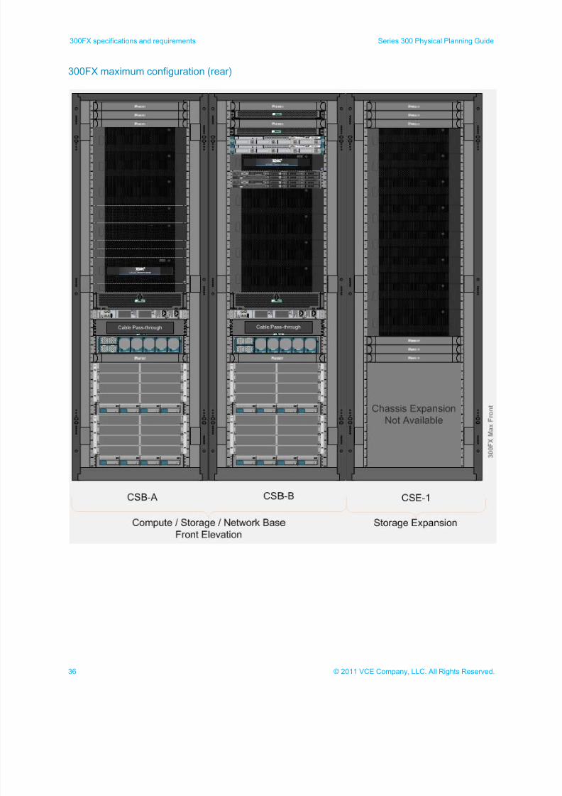
The 300FX maximum configuration includes:
Compute/storage base cabinet A (CSB-A)
Compute/storage base cabinet B (CSB-B)
Compute/storage expansion cabinet 1 (CSE-1) (chassis expansion is not currently available)
The following illustrations show the maximum configuration options for the 300FX.
7/21/2019 VCE Vblock™ Systems 300 Physical Planning Guide (Cisco UCS)
http://slidepdf.com/reader/full/vce-vblock-systems-300-physical-planning-guide-cisco-ucs 36/132
36 © 2011 VCE Company, LLC. All Rights Reserved.
300FX specifications and requirements Series 300 Physical Planning Guide
300FX maximum configuration (rear)
7/21/2019 VCE Vblock™ Systems 300 Physical Planning Guide (Cisco UCS)
http://slidepdf.com/reader/full/vce-vblock-systems-300-physical-planning-guide-cisco-ucs 37/132
37© 2011 VCE Company, LLC. All Rights Reserved.
Series 300 Physical Planning Guide 300FX specifications and requirements
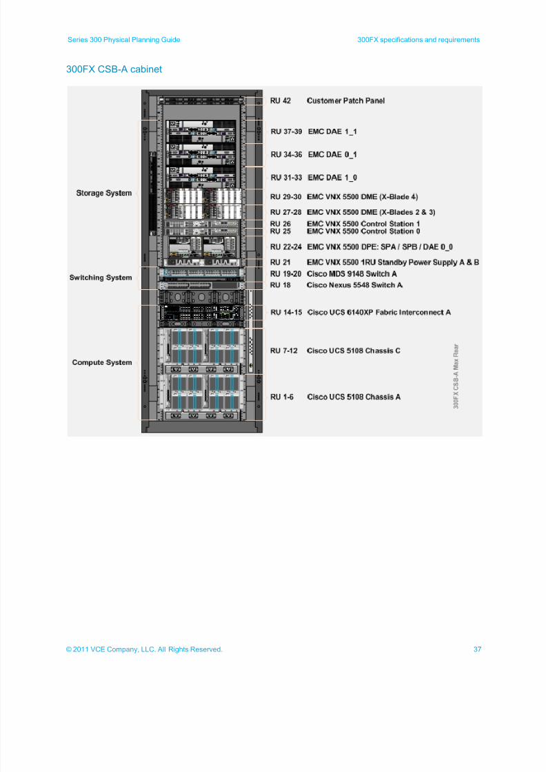
300FX CSB-A cabinet
7/21/2019 VCE Vblock™ Systems 300 Physical Planning Guide (Cisco UCS)
http://slidepdf.com/reader/full/vce-vblock-systems-300-physical-planning-guide-cisco-ucs 38/132
38 © 2011 VCE Company, LLC. All Rights Reserved.
300FX specifications and requirements Series 300 Physical Planning Guide
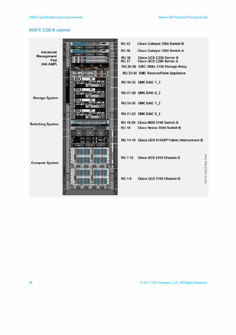
300FX CSB-B cabinet
7/21/2019 VCE Vblock™ Systems 300 Physical Planning Guide (Cisco UCS)
http://slidepdf.com/reader/full/vce-vblock-systems-300-physical-planning-guide-cisco-ucs 39/132
39© 2011 VCE Company, LLC. All Rights Reserved.
Series 300 Physical Planning Guide 300FX specifications and requirements
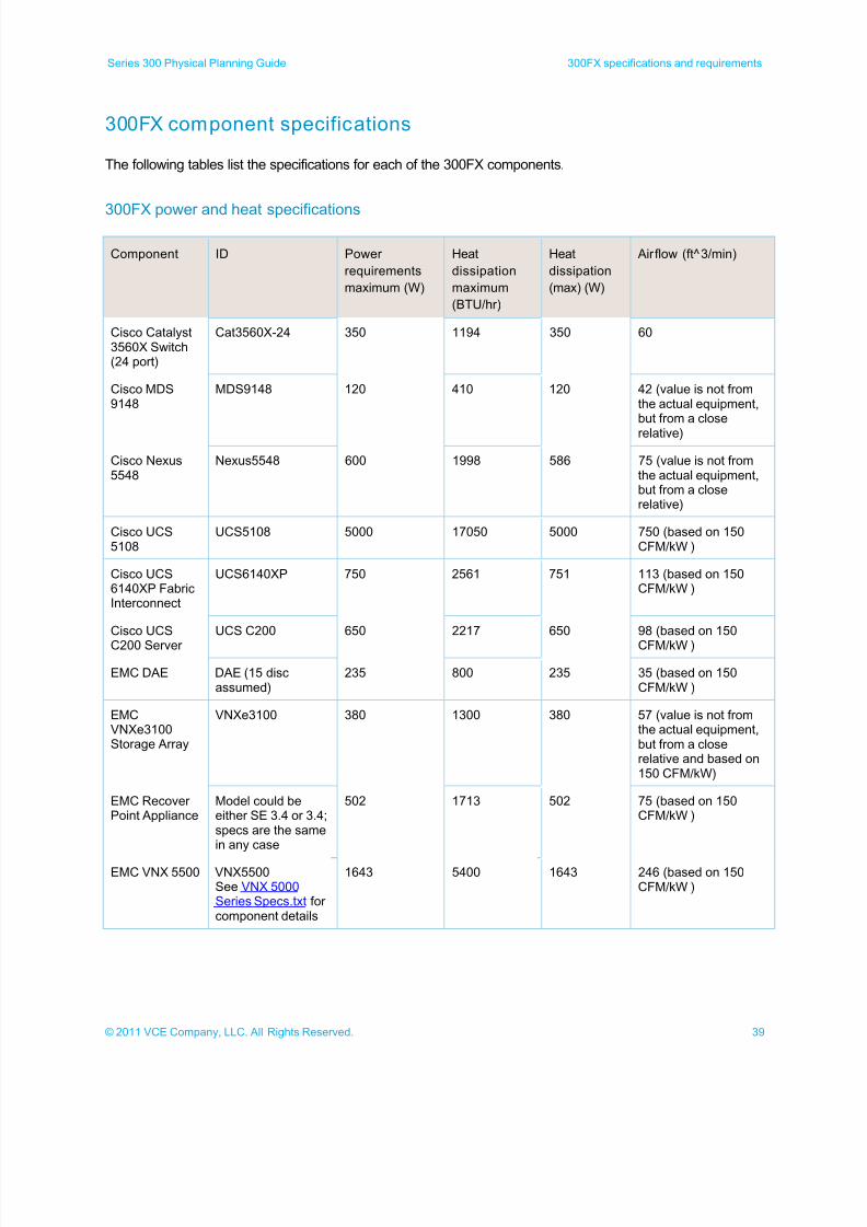
300FX component specifications
The following tables list the specifications for each of the 300FX components.
300FX power and heat specifications
Component ID Power
requirements
maximum (W)
Heat
dissipation
maximum
(BTU/hr)
Heat
dissipation
(max) (W)
Airflow (ft^3/min)
Cisco Catalyst3560X Switch(24 port)
Cat3560X-24 350 1194 350 60
Cisco MDS9148
MDS9148 120 410 120 42 (value is not fromthe actual equipment,but from a close
relative)
Cisco Nexus5548
Nexus5548 600 1998 586 75 (value is not fromthe actual equipment,but from a closerelative)
Cisco UCS5108
UCS5108 5000 17050 5000 750 (based on 150CFM/kW )
Cisco UCS6140XP FabricInterconnect
UCS6140XP 750 2561 751 113 (based on 150CFM/kW )
Cisco UCS
C200 Server
UCS C200 650 2217 650 98 (based on 150
CFM/kW )
EMC DAE DAE (15 discassumed)
235 800 235 35 (based on 150CFM/kW )
EMCVNXe3100Storage Array
VNXe3100 380 1300 380 57 (value is not fromthe actual equipment,but from a closerelative and based on150 CFM/kW)
EMC RecoverPoint Appliance
Model could beeither SE 3.4 or 3.4;specs are the samein any case
502 1713 502 75 (based on 150CFM/kW )
EMC VNX 5500 VNX5500See VNX 5000Series Specs.txt forcomponent details
1643 5400 1643 246 (based on 150CFM/kW )

7/21/2019 VCE Vblock™ Systems 300 Physical Planning Guide (Cisco UCS)
http://slidepdf.com/reader/full/vce-vblock-systems-300-physical-planning-guide-cisco-ucs 40/132
40 © 2011 VCE Company, LLC. All Rights Reserved.
300FX specifications and requirements Series 300 Physical Planning Guide
Cisco Unified Computing System Power Calculator
To calculate the current draw and heat dissipation of each blade in a specific configuration, use the Cisco
Unified Computing System Power calculator at
www.cisco.com/assets/cdc_content_elements/flash/dataCenter/cisco_ucs_power_calculator/ .
300FX physical specifications
Component Height x width x depth (inches) Number rack units Weight (lb)
Cisco Catalyst 3560X Switch (24 port) 1.73 x 17.5 x 14.85 1 13.2
Cisco MDS 9148 1.72 x 17.51 x 19.78 2 22.2
Cisco Nexus 5548 1.72 x 17.3 x 29.5 1 32
Cisco UCS 5108 10.5 x 17.5 x 32 6 255
Cisco UCS 6140XP Fabric Interconnect 3.47 x 17.3 x 30 2 50
Cisco UCS C200 Server 1.7 x 16.92 x 27.8 1 33
EMC DAE 5.25 x 17.6 x 14 3 68
EMC VNXe3100 Storage Array 3.40 x 17.5 x 20.0 2 60.5
EMC Recover Point Appliance 1.68 x 17.44 x 30.4 1 39
EMC VNX 5500 DME 17.5 x 17.62 x 24.25 10 284.4
7/21/2019 VCE Vblock™ Systems 300 Physical Planning Guide (Cisco UCS)
http://slidepdf.com/reader/full/vce-vblock-systems-300-physical-planning-guide-cisco-ucs 41/132
41© 2011 VCE Company, LLC. All Rights Reserved.
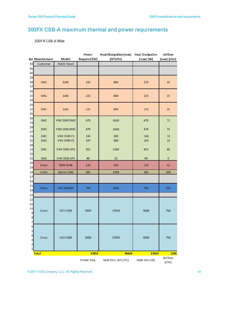
Series 300 Physical Planning Guide 300FX specifications and requirements
300FX CSB-A maximum thermal and power requirements
7/21/2019 VCE Vblock™ Systems 300 Physical Planning Guide (Cisco UCS)
http://slidepdf.com/reader/full/vce-vblock-systems-300-physical-planning-guide-cisco-ucs 42/132
42 © 2011 VCE Company, LLC. All Rights Reserved.
300FX specifications and requirements Series 300 Physical Planning Guide
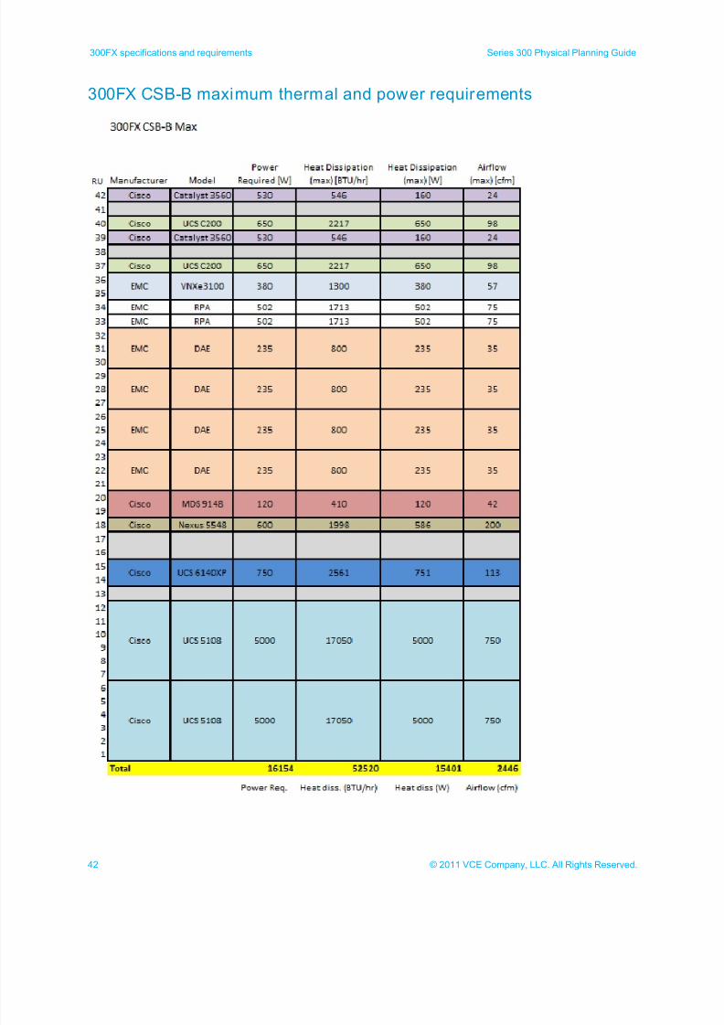
300FX CSB-B maximum thermal and power requirements
7/21/2019 VCE Vblock™ Systems 300 Physical Planning Guide (Cisco UCS)
http://slidepdf.com/reader/full/vce-vblock-systems-300-physical-planning-guide-cisco-ucs 43/132
43© 2011 VCE Company, LLC. All Rights Reserved.
Series 300 Physical Planning Guide 300FX specifications and requirements
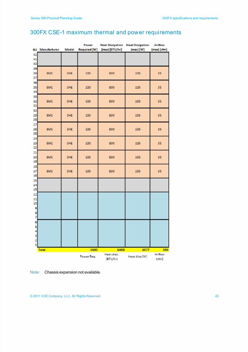
300FX CSE-1 maximum thermal and power requirements
Note: Chassis expansion not available.
7/21/2019 VCE Vblock™ Systems 300 Physical Planning Guide (Cisco UCS)
http://slidepdf.com/reader/full/vce-vblock-systems-300-physical-planning-guide-cisco-ucs 44/132
44 © 2011 VCE Company, LLC. All Rights Reserved.
300FX specifications and requirements Series 300 Physical Planning Guide
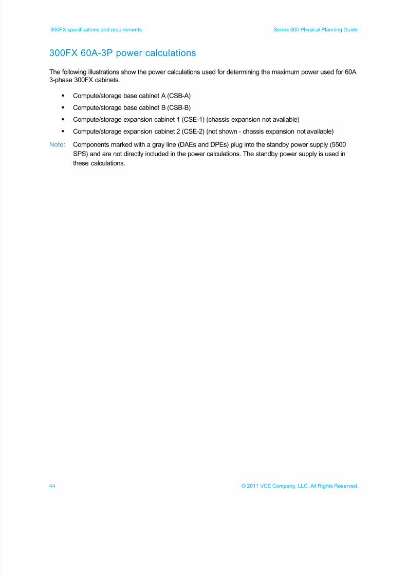
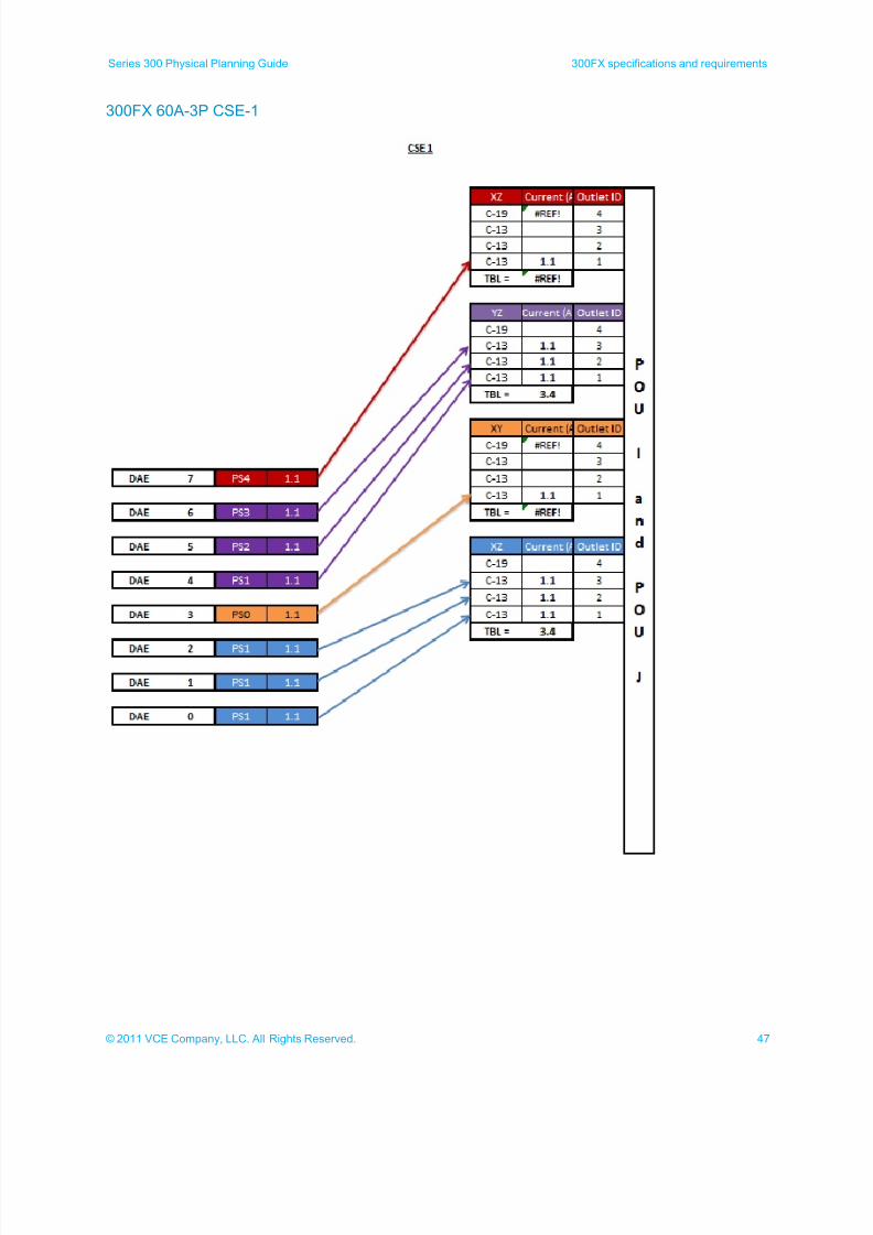
300FX 60A-3P power calculations
The following illustrations show the power calculations used for determining the maximum power used for 60A
3-phase 300FX cabinets.
Compute/storage base cabinet A (CSB-A)
Compute/storage base cabinet B (CSB-B)
Compute/storage expansion cabinet 1 (CSE-1) (chassis expansion not available)
Compute/storage expansion cabinet 2 (CSE-2) (not shown - chassis expansion not available)
Note: Components marked with a gray line (DAEs and DPEs) plug into the standby power supply (5500
SPS) and are not directly included in the power calculations. The standby power supply is used in
these calculations.
7/21/2019 VCE Vblock™ Systems 300 Physical Planning Guide (Cisco UCS)
http://slidepdf.com/reader/full/vce-vblock-systems-300-physical-planning-guide-cisco-ucs 45/132
45© 2011 VCE Company, LLC. All Rights Reserved.
Series 300 Physical Planning Guide 300FX specifications and requirements
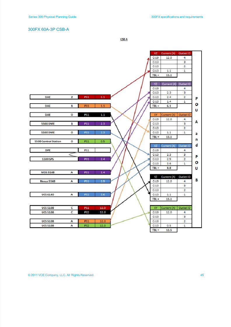
300FX 60A-3P CSB-A
7/21/2019 VCE Vblock™ Systems 300 Physical Planning Guide (Cisco UCS)
http://slidepdf.com/reader/full/vce-vblock-systems-300-physical-planning-guide-cisco-ucs 46/132
46 © 2011 VCE Company, LLC. All Rights Reserved.
300FX specifications and requirements Series 300 Physical Planning Guide
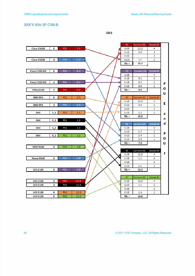
300FX 60A-3P CSB-B
7/21/2019 VCE Vblock™ Systems 300 Physical Planning Guide (Cisco UCS)
http://slidepdf.com/reader/full/vce-vblock-systems-300-physical-planning-guide-cisco-ucs 47/132
47© 2011 VCE Company, LLC. All Rights Reserved.
Series 300 Physical Planning Guide 300FX specifications and requirements
300FX 60A-3P CSE-1
7/21/2019 VCE Vblock™ Systems 300 Physical Planning Guide (Cisco UCS)
http://slidepdf.com/reader/full/vce-vblock-systems-300-physical-planning-guide-cisco-ucs 48/132
48 © 2011 VCE Company, LLC. All Rights Reserved.
300FX specifications and requirements Series 300 Physical Planning Guide
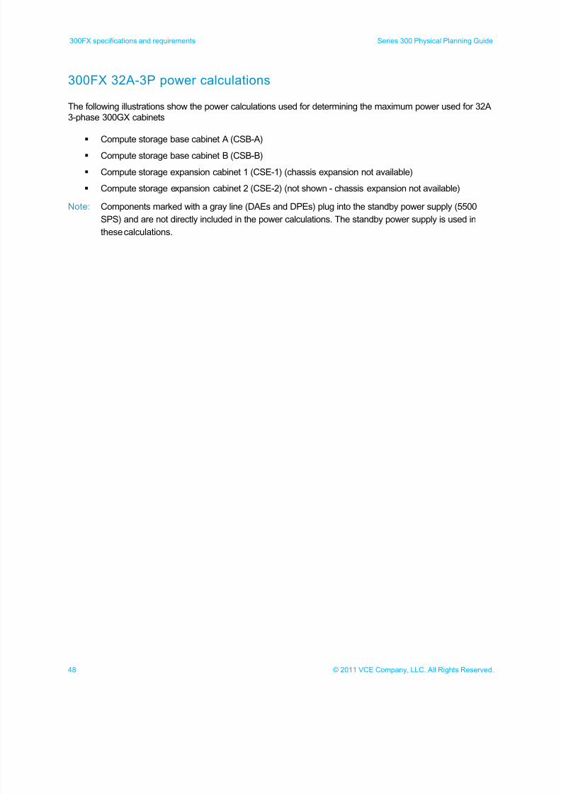
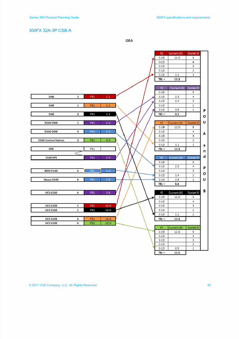
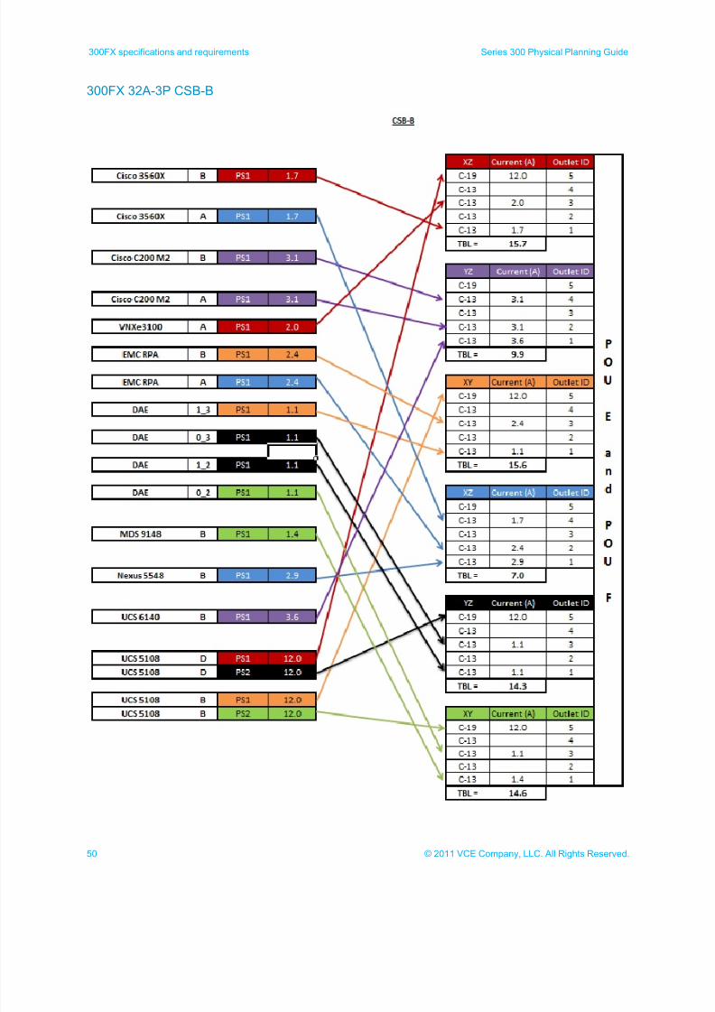
300FX 32A-3P power calculations
The following illustrations show the power calculations used for determining the maximum power used for 32A
3-phase 300GX cabinets
Compute storage base cabinet A (CSB-A)
Compute storage base cabinet B (CSB-B)
Compute storage expansion cabinet 1 (CSE-1) (chassis expansion not available)
Compute storage expansion cabinet 2 (CSE-2) (not shown - chassis expansion not available)
Note: Components marked with a gray line (DAEs and DPEs) plug into the standby power supply (5500
SPS) and are not directly included in the power calculations. The standby power supply is used in
these calculations.
7/21/2019 VCE Vblock™ Systems 300 Physical Planning Guide (Cisco UCS)
http://slidepdf.com/reader/full/vce-vblock-systems-300-physical-planning-guide-cisco-ucs 49/132
49© 2011 VCE Company, LLC. All Rights Reserved.
Series 300 Physical Planning Guide 300FX specifications and requirements
300FX 32A-3P CSB-A
7/21/2019 VCE Vblock™ Systems 300 Physical Planning Guide (Cisco UCS)
http://slidepdf.com/reader/full/vce-vblock-systems-300-physical-planning-guide-cisco-ucs 50/132
50 © 2011 VCE Company, LLC. All Rights Reserved.
300FX specifications and requirements Series 300 Physical Planning Guide
300FX 32A-3P CSB-B
7/21/2019 VCE Vblock™ Systems 300 Physical Planning Guide (Cisco UCS)
http://slidepdf.com/reader/full/vce-vblock-systems-300-physical-planning-guide-cisco-ucs 51/132
51© 2011 VCE Company, LLC. All Rights Reserved.
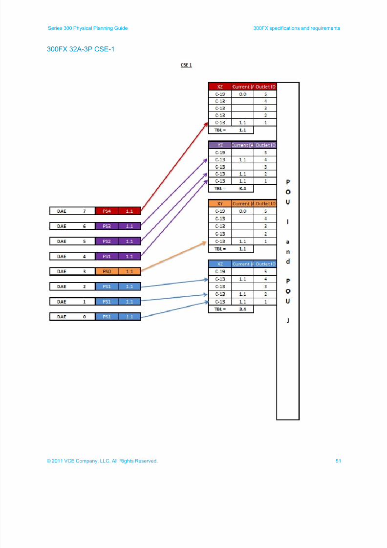
Series 300 Physical Planning Guide 300FX specifications and requirements
300FX 32A-3P CSE-1
7/21/2019 VCE Vblock™ Systems 300 Physical Planning Guide (Cisco UCS)
http://slidepdf.com/reader/full/vce-vblock-systems-300-physical-planning-guide-cisco-ucs 52/132
52 © 2011 VCE Company, LLC. All Rights Reserved.
300FX specifications and requirements Series 300 Physical Planning Guide
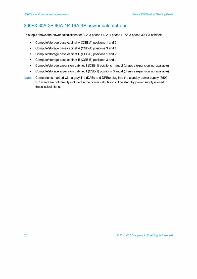
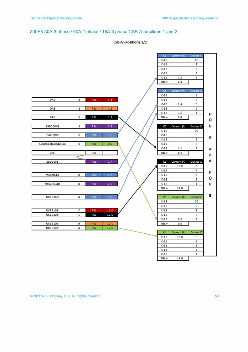
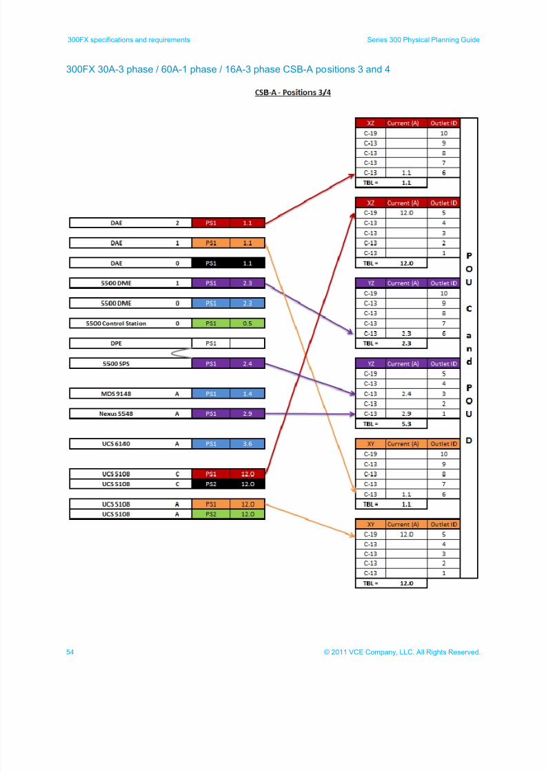
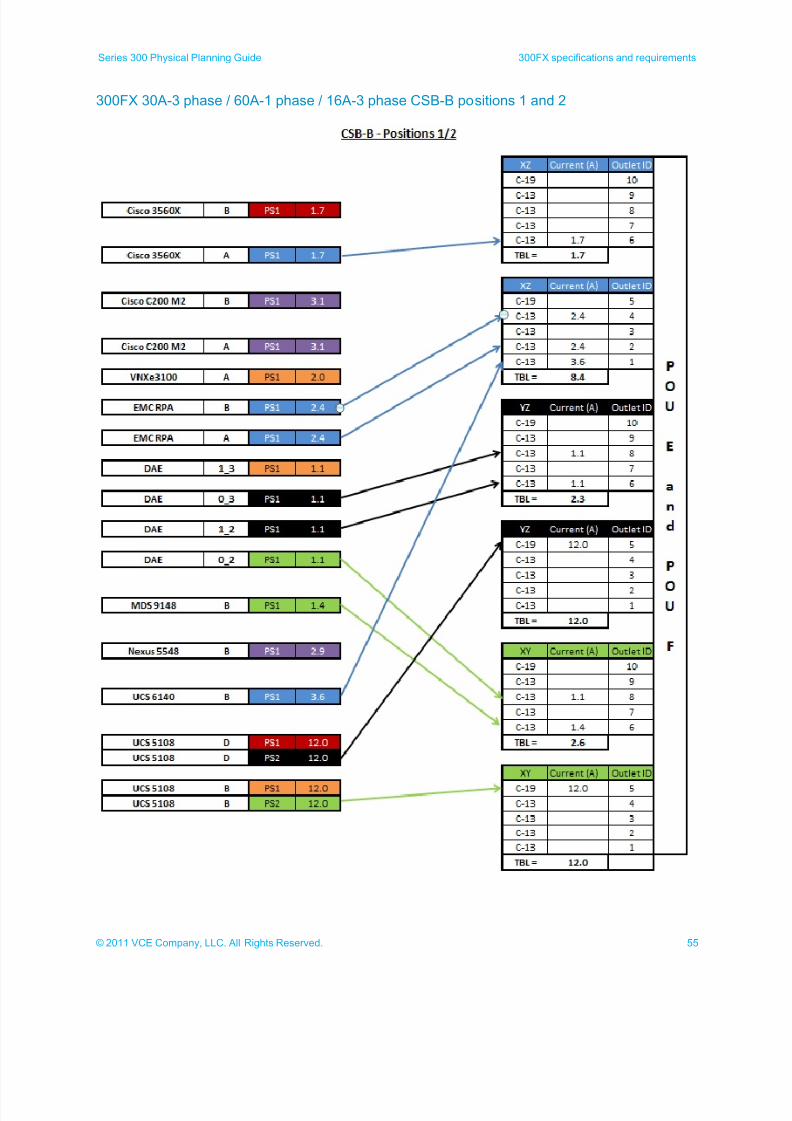
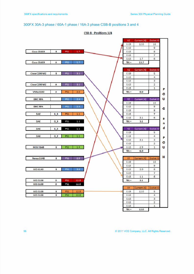
300FX 30A-3P 60A-1P 16A-3P power calculations
This topic shows the power calculations for 30A-3 phase / 60A-1 phase / 16A-3 phase 300FX cabinets:
Compute/storage base cabinet A (CSB-A) positions 1 and 2
Compute/storage base cabinet A (CSB-A) positions 3 and 4
Compute/storage base cabinet B (CSB-B) positions 1 and 2
Compute/storage base cabinet B (CSB-B) positions 3 and 4
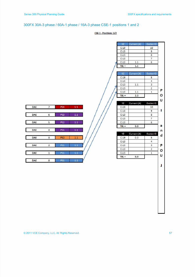
Compute/storage expansion cabinet 1 (CSE-1) positions 1 and 2 (chassis expansion not available)
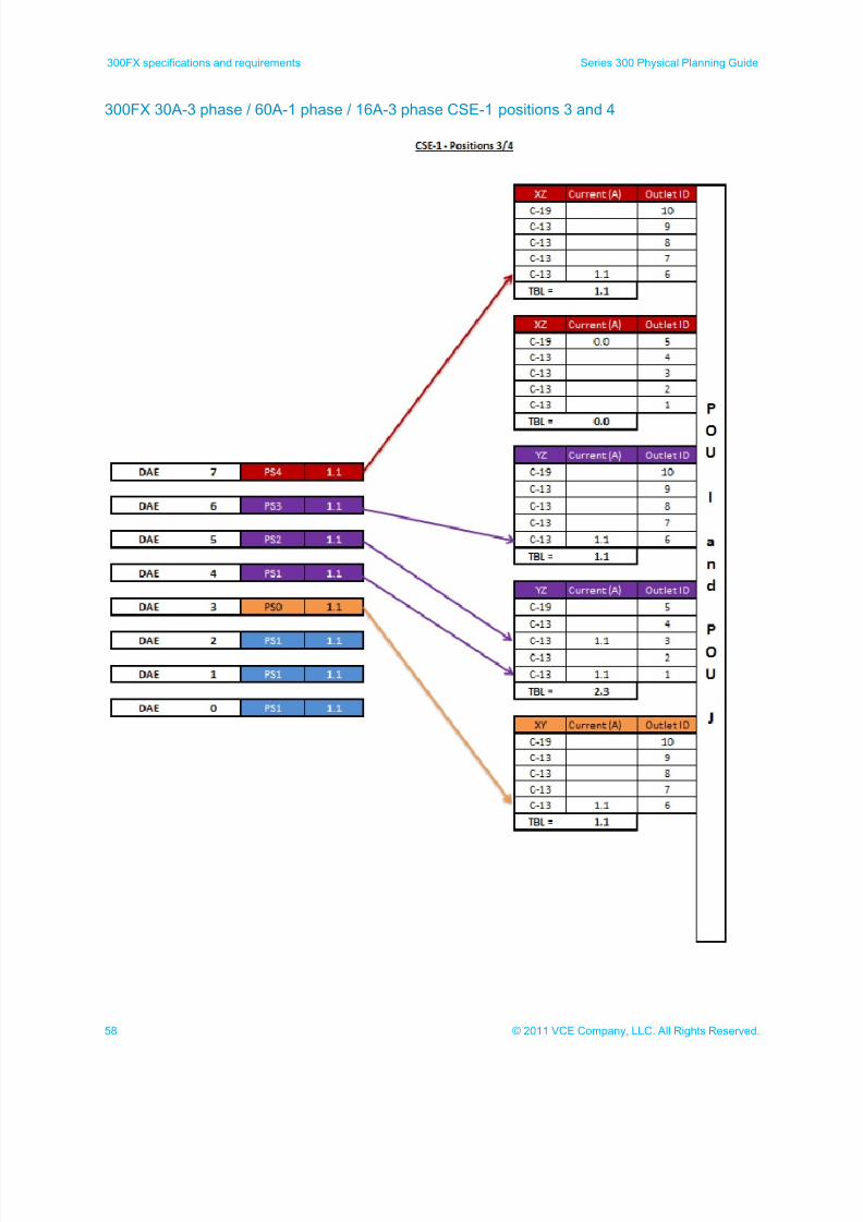
Compute/storage expansion cabinet 1 (CSE-1) positions 3 and 4 (chassis expansion not available)
Note: Components marked with a gray line (DAEs and DPEs) plug into the standby power supply (5500
SPS) and are not directly included in the power calculations. The standby power supply is used in
these calculations.
7/21/2019 VCE Vblock™ Systems 300 Physical Planning Guide (Cisco UCS)
http://slidepdf.com/reader/full/vce-vblock-systems-300-physical-planning-guide-cisco-ucs 53/132
53© 2011 VCE Company, LLC. All Rights Reserved.
Series 300 Physical Planning Guide 300FX specifications and requirements
300FX 30A-3 phase / 60A-1 phase / 16A-3 phase CSB-A positions 1 and 2
7/21/2019 VCE Vblock™ Systems 300 Physical Planning Guide (Cisco UCS)
http://slidepdf.com/reader/full/vce-vblock-systems-300-physical-planning-guide-cisco-ucs 54/132
54 © 2011 VCE Company, LLC. All Rights Reserved.
300FX specifications and requirements Series 300 Physical Planning Guide
300FX 30A-3 phase / 60A-1 phase / 16A-3 phase CSB-A positions 3 and 4
7/21/2019 VCE Vblock™ Systems 300 Physical Planning Guide (Cisco UCS)
http://slidepdf.com/reader/full/vce-vblock-systems-300-physical-planning-guide-cisco-ucs 55/132
55© 2011 VCE Company, LLC. All Rights Reserved.
Series 300 Physical Planning Guide 300FX specifications and requirements
300FX 30A-3 phase / 60A-1 phase / 16A-3 phase CSB-B positions 1 and 2
7/21/2019 VCE Vblock™ Systems 300 Physical Planning Guide (Cisco UCS)
http://slidepdf.com/reader/full/vce-vblock-systems-300-physical-planning-guide-cisco-ucs 56/132
56 © 2011 VCE Company, LLC. All Rights Reserved.
300FX specifications and requirements Series 300 Physical Planning Guide
300FX 30A-3 phase / 60A-1 phase / 16A-3 phase CSB-B positions 3 and 4
7/21/2019 VCE Vblock™ Systems 300 Physical Planning Guide (Cisco UCS)
http://slidepdf.com/reader/full/vce-vblock-systems-300-physical-planning-guide-cisco-ucs 57/132
57© 2011 VCE Company, LLC. All Rights Reserved.
Series 300 Physical Planning Guide 300FX specifications and requirements
300FX 30A-3 phase / 60A-1 phase / 16A-3 phase CSE-1 positions 1 and 2
7/21/2019 VCE Vblock™ Systems 300 Physical Planning Guide (Cisco UCS)
http://slidepdf.com/reader/full/vce-vblock-systems-300-physical-planning-guide-cisco-ucs 58/132
58 © 2011 VCE Company, LLC. All Rights Reserved.
300FX specifications and requirements Series 300 Physical Planning Guide
300FX 30A-3 phase / 60A-1 phase / 16A-3 phase CSE-1 positions 3 and 4
7/21/2019 VCE Vblock™ Systems 300 Physical Planning Guide (Cisco UCS)
http://slidepdf.com/reader/full/vce-vblock-systems-300-physical-planning-guide-cisco-ucs 59/132
59© 2011 VCE Company, LLC. All Rights Reserved.
Series 300 Physical Planning Guide 300GX specifications and requirements
300GX specifications and requirements
300GX cabinet layouts
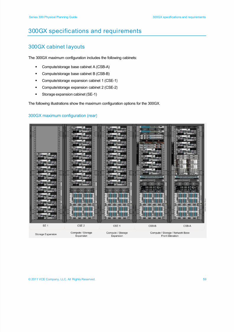
The 300GX maximum configuration includes the following cabinets:
Compute/storage base cabinet A (CSB-A)
Compute/storage base cabinet B (CSB-B)
Compute/storage expansion cabinet 1 (CSE-1)
Compute/storage expansion cabinet 2 (CSE-2)
Storage expansion cabinet (SE-1)
The following illustrations show the maximum configuration options for the 300GX.
300GX maximum configuration (rear)
7/21/2019 VCE Vblock™ Systems 300 Physical Planning Guide (Cisco UCS)
http://slidepdf.com/reader/full/vce-vblock-systems-300-physical-planning-guide-cisco-ucs 60/132
60 © 2011 VCE Company, LLC. All Rights Reserved.
300GX specifications and requirements Series 300 Physical Planning Guide
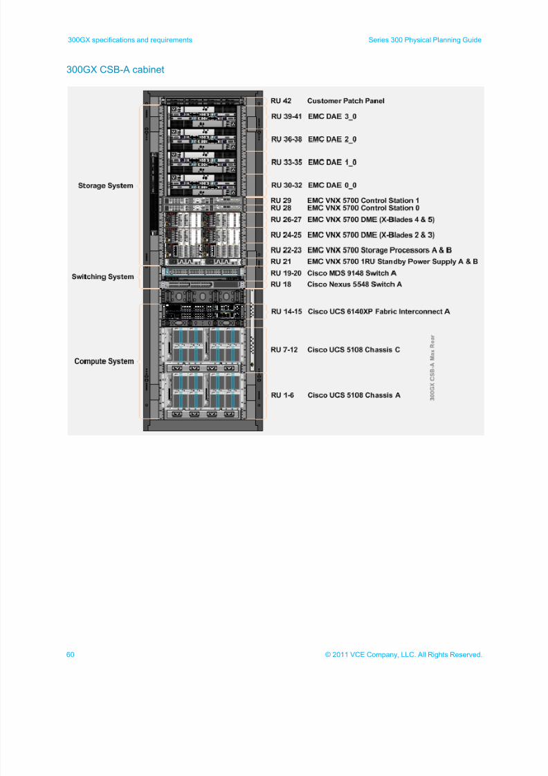
300GX CSB-A cabinet
7/21/2019 VCE Vblock™ Systems 300 Physical Planning Guide (Cisco UCS)
http://slidepdf.com/reader/full/vce-vblock-systems-300-physical-planning-guide-cisco-ucs 61/132
61© 2011 VCE Company, LLC. All Rights Reserved.
Series 300 Physical Planning Guide 300GX specifications and requirements
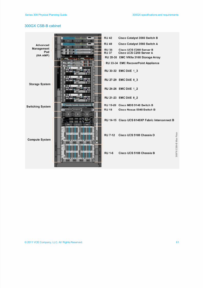
300GX CSB-B cabinet
7/21/2019 VCE Vblock™ Systems 300 Physical Planning Guide (Cisco UCS)
http://slidepdf.com/reader/full/vce-vblock-systems-300-physical-planning-guide-cisco-ucs 62/132
62 © 2011 VCE Company, LLC. All Rights Reserved.
300GX specifications and requirements Series 300 Physical Planning Guide
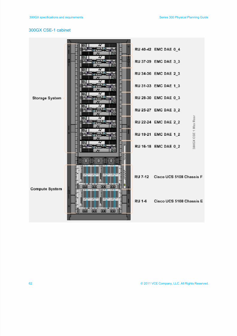
300GX CSE-1 cabinet
7/21/2019 VCE Vblock™ Systems 300 Physical Planning Guide (Cisco UCS)
http://slidepdf.com/reader/full/vce-vblock-systems-300-physical-planning-guide-cisco-ucs 63/132
63© 2011 VCE Company, LLC. All Rights Reserved.
Series 300 Physical Planning Guide 300GX specifications and requirements
300GX CSE-2 cabinet
7/21/2019 VCE Vblock™ Systems 300 Physical Planning Guide (Cisco UCS)
http://slidepdf.com/reader/full/vce-vblock-systems-300-physical-planning-guide-cisco-ucs 64/132
64 © 2011 VCE Company, LLC. All Rights Reserved.
300GX specifications and requirements Series 300 Physical Planning Guide
300GX SE-1 cabinet
7/21/2019 VCE Vblock™ Systems 300 Physical Planning Guide (Cisco UCS)
http://slidepdf.com/reader/full/vce-vblock-systems-300-physical-planning-guide-cisco-ucs 65/132
65© 2011 VCE Company, LLC. All Rights Reserved.
Series 300 Physical Planning Guide 300GX specifications and requirements
300GX component specifications
The following tables list the specifications for each of the 300GX components.
300GX power and heat specifications
Model ID Power
requirements
maximum (W)
Heat
dissipation
maximum
(BTU/hr)
Heat
dissipation
(max) (W)
Airflow (ft^3/min)
Cisco Catalyst3560X Switch(24 port)
Cat3560X-24 350 1194 350 60
Cisco MDS9148
MDS9148 120 410 120 42 (value is not fromthe actual equipment,but from a close
relative)
Cisco Nexus5548
Nexus5548 600 1998 586 75 (value is not fromthe actual equipment,but from a closerelative)
Cisco UCS5108
UCS5108 5000 17050 5000 750 (based on 150CFM/kW)
Cisco 6140XPFabricInterconnect
UCS6140XP 750 2561 751 113 (based on 150CFM/kW)
Cisco UCS
C200 Server
UCS C200 650 2217 650 98 (based on 150
CFM/kW)
EMC DAE DAE(15 disc assumed)
235 800 235 35 (based on 150CFM/kW)
EMCVNXe3100Storage Array
VNXe310 380 1300 380 57 (value is not fromthe actual equipment,but from a closerelative and based on150 CFM/kW)
EMC RecoverPoint Appliance
Model could beeither SE 3.4 or 3.4;specs are the samein any case
502 1713 502 75 (based on 150CFM/kW)
EMC VNX 5700 UNX5700See VNX 5000Series Specs.txt forcomponent details
1748 5750 1686 253 (based on 150CFM/kW)
7/21/2019 VCE Vblock™ Systems 300 Physical Planning Guide (Cisco UCS)
http://slidepdf.com/reader/full/vce-vblock-systems-300-physical-planning-guide-cisco-ucs 66/132
66 © 2011 VCE Company, LLC. All Rights Reserved.
300GX specifications and requirements Series 300 Physical Planning Guide
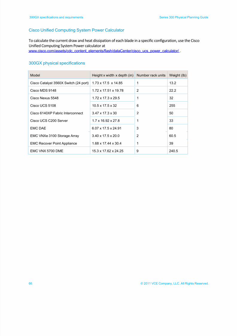
Cisco Unified Computing System Power Calculator
To calculate the current draw and heat dissipation of each blade in a specific configuration, use the Cisco
Unified Computing System Power calculator at
www.cisco.com/assets/cdc_content_elements/flash/dataCenter/cisco_ucs_power_calculator/ .
300GX physical specifications
Model Height x width x depth (in) Number rack units Weight (lb)
Cisco Catalyst 3560X Switch (24 port) 1.73 x 17.5 x 14.85 1 13.2
Cisco MDS 9148 1.72 x 17.51 x 19.78 2 22.2
Cisco Nexus 5548 1.72 x 17.3 x 29.5 1 32
Cisco UCS 5108 10.5 x 17.5 x 32 6 255
Cisco 6140XP Fabric Interconnect 3.47 x 17.3 x 30 2 50
Cisco UCS C200 Server 1.7 x 16.92 x 27.8 1 33
EMC DAE 6.07 x 17.5 x 24.91 3 80
EMC VNXe 3100 Storage Array 3.40 x 17.5 x 20.0 2 60.5
EMC Recover Point Appliance 1.68 x 17.44 x 30.4 1 39
EMC VNX 5700 DME 15.3 x 17.62 x 24.25 9 240.5
7/21/2019 VCE Vblock™ Systems 300 Physical Planning Guide (Cisco UCS)
http://slidepdf.com/reader/full/vce-vblock-systems-300-physical-planning-guide-cisco-ucs 67/132
67© 2011 VCE Company, LLC. All Rights Reserved.
Series 300 Physical Planning Guide 300GX specifications and requirements
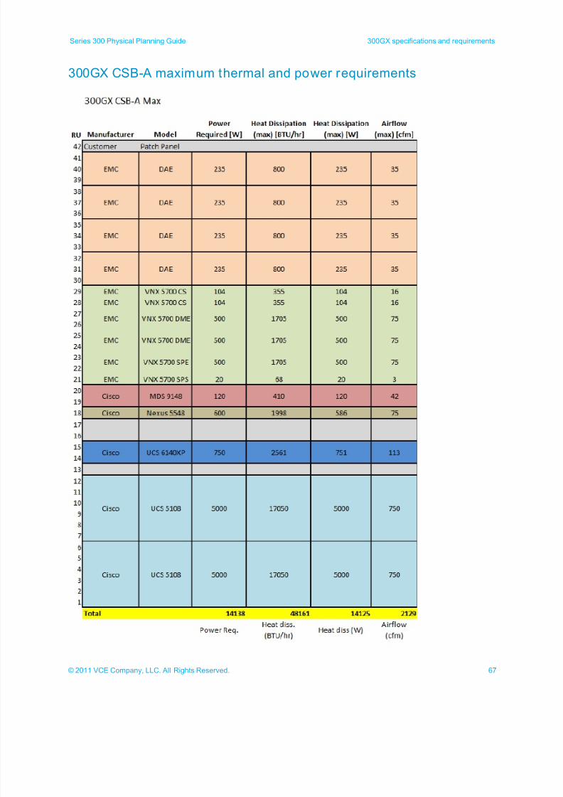
300GX CSB-A maximum thermal and power requirements
7/21/2019 VCE Vblock™ Systems 300 Physical Planning Guide (Cisco UCS)
http://slidepdf.com/reader/full/vce-vblock-systems-300-physical-planning-guide-cisco-ucs 68/132
68 © 2011 VCE Company, LLC. All Rights Reserved.
300GX specifications and requirements Series 300 Physical Planning Guide
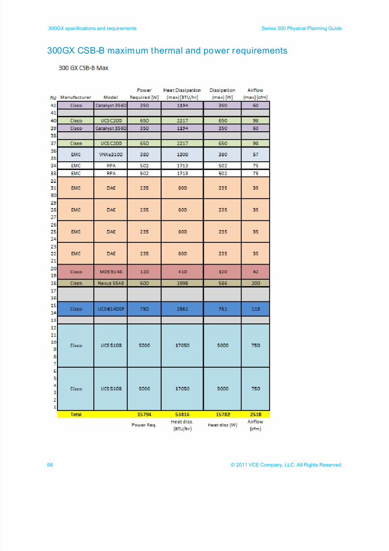
300GX CSB-B maximum thermal and power requirements
7/21/2019 VCE Vblock™ Systems 300 Physical Planning Guide (Cisco UCS)
http://slidepdf.com/reader/full/vce-vblock-systems-300-physical-planning-guide-cisco-ucs 69/132
69© 2011 VCE Company, LLC. All Rights Reserved.
Series 300 Physical Planning Guide 300GX specifications and requirements
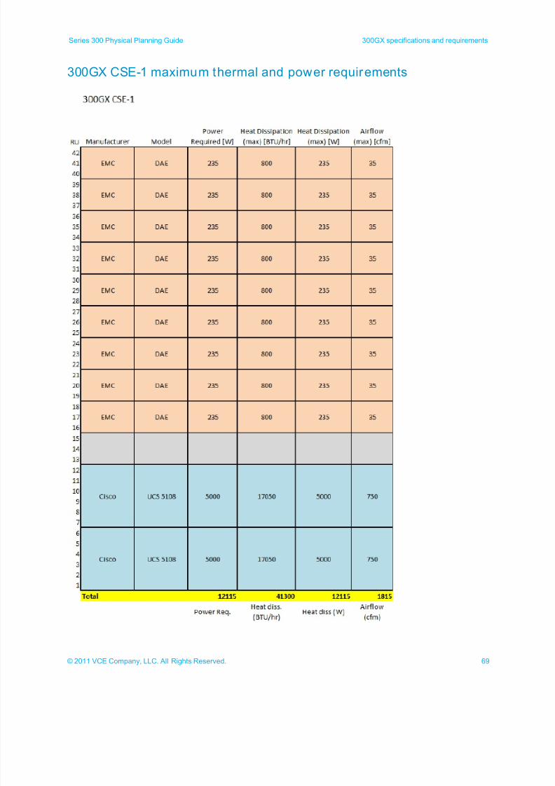
300GX CSE-1 maximum thermal and power requirements
7/21/2019 VCE Vblock™ Systems 300 Physical Planning Guide (Cisco UCS)
http://slidepdf.com/reader/full/vce-vblock-systems-300-physical-planning-guide-cisco-ucs 70/132
70 © 2011 VCE Company, LLC. All Rights Reserved.
300GX specifications and requirements Series 300 Physical Planning Guide
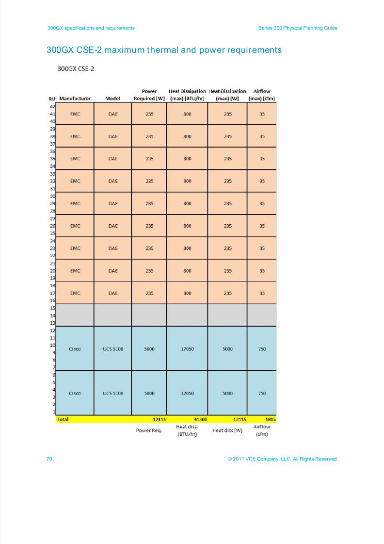
300GX CSE-2 maximum thermal and power requirements
7/21/2019 VCE Vblock™ Systems 300 Physical Planning Guide (Cisco UCS)
http://slidepdf.com/reader/full/vce-vblock-systems-300-physical-planning-guide-cisco-ucs 71/132
71© 2011 VCE Company, LLC. All Rights Reserved.
Series 300 Physical Planning Guide 300GX specifications and requirements
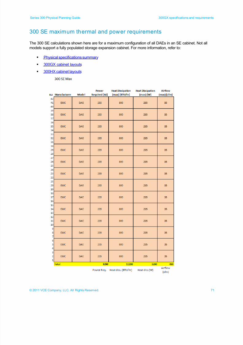
300 SE maximum thermal and power requirements
The 300 SE calculations shown here are for a maximum configuration of all DAEs in an SE cabinet. Not all
models support a fully populated storage expansion cabinet. For more information, refer to:
Physical specifications summary
300GX cabinet layouts
300HX cabinet layouts
7/21/2019 VCE Vblock™ Systems 300 Physical Planning Guide (Cisco UCS)
http://slidepdf.com/reader/full/vce-vblock-systems-300-physical-planning-guide-cisco-ucs 72/132
72 © 2011 VCE Company, LLC. All Rights Reserved.
300GX specifications and requirements Series 300 Physical Planning Guide
300GX 60A-3P power calculations
The following illustrations show the power calculations used for determining the maximum power used for 60A
3-phase 300GX cabinets.
Compute/storage base cabinet A (CSB-A)
Compute/storage base cabinet B (CSB-B)
Compute/storage expansion cabinet 1 (CSE-1)
Compute/storage expansion cabinet 2 (CSE-2)
Storage expansion cabinet 1 (SE-1)
Note: Components marked with a gray line (DAEs and DPEs) plug into the standby power supply (5700
SPS) and are not directly included in the power calculations. The standby power supply is used in
these calculations.
7/21/2019 VCE Vblock™ Systems 300 Physical Planning Guide (Cisco UCS)
http://slidepdf.com/reader/full/vce-vblock-systems-300-physical-planning-guide-cisco-ucs 73/132
73© 2011 VCE Company, LLC. All Rights Reserved.
Series 300 Physical Planning Guide 300GX specifications and requirements
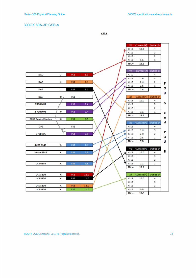
300GX 60A-3P CSB-A
7/21/2019 VCE Vblock™ Systems 300 Physical Planning Guide (Cisco UCS)
http://slidepdf.com/reader/full/vce-vblock-systems-300-physical-planning-guide-cisco-ucs 74/132
74 © 2011 VCE Company, LLC. All Rights Reserved.
300GX specifications and requirements Series 300 Physical Planning Guide
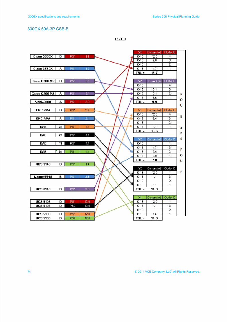
300GX 60A-3P CSB-B
7/21/2019 VCE Vblock™ Systems 300 Physical Planning Guide (Cisco UCS)
http://slidepdf.com/reader/full/vce-vblock-systems-300-physical-planning-guide-cisco-ucs 75/132
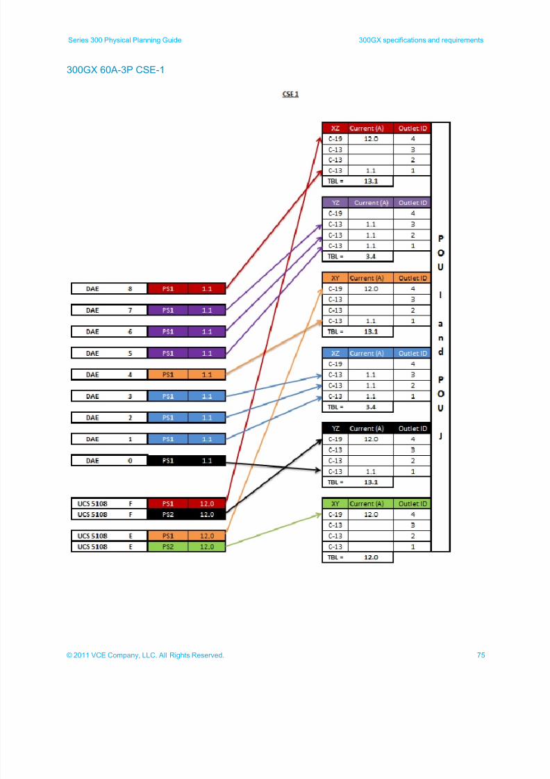
75© 2011 VCE Company, LLC. All Rights Reserved.
Series 300 Physical Planning Guide 300GX specifications and requirements
300GX 60A-3P CSE-1
7/21/2019 VCE Vblock™ Systems 300 Physical Planning Guide (Cisco UCS)
http://slidepdf.com/reader/full/vce-vblock-systems-300-physical-planning-guide-cisco-ucs 76/132
76 © 2011 VCE Company, LLC. All Rights Reserved.
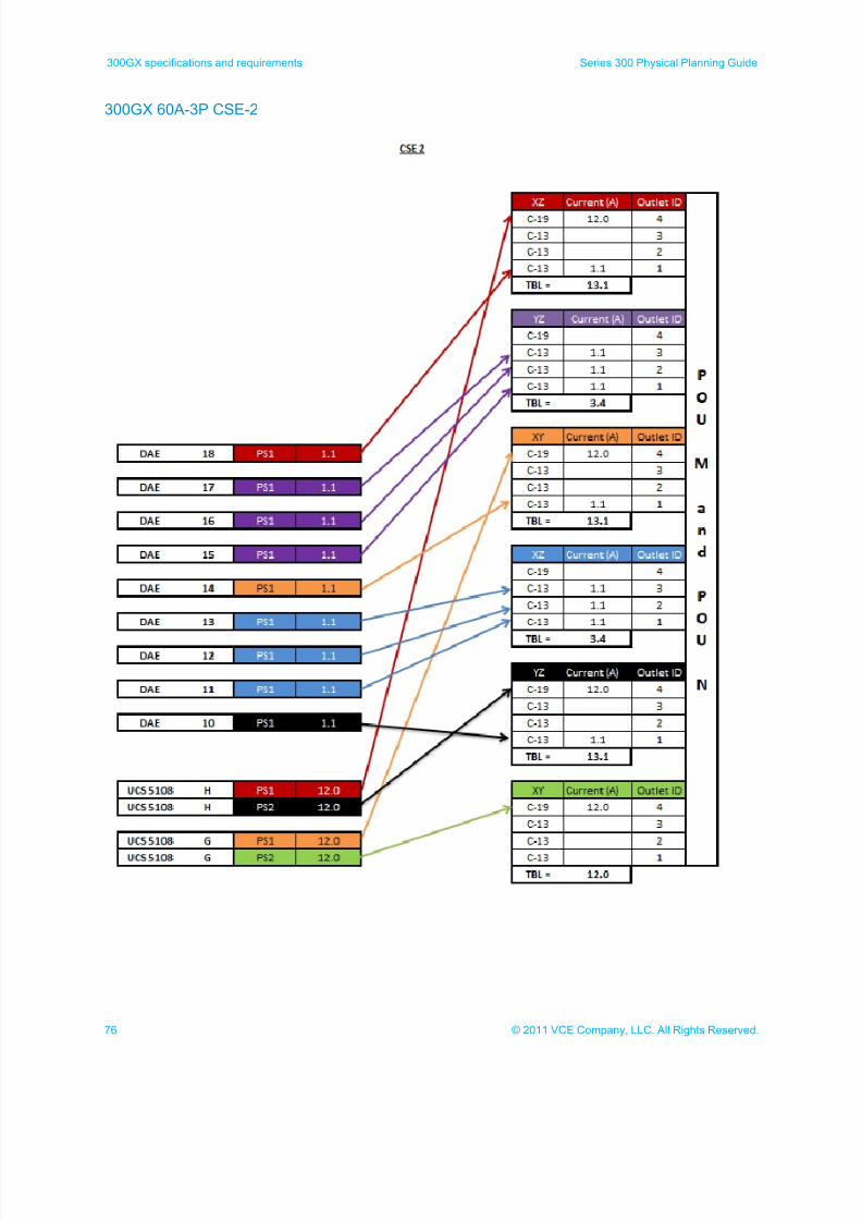
300GX specifications and requirements Series 300 Physical Planning Guide
300GX 60A-3P CSE-2
7/21/2019 VCE Vblock™ Systems 300 Physical Planning Guide (Cisco UCS)
http://slidepdf.com/reader/full/vce-vblock-systems-300-physical-planning-guide-cisco-ucs 77/132
77© 2011 VCE Company, LLC. All Rights Reserved.
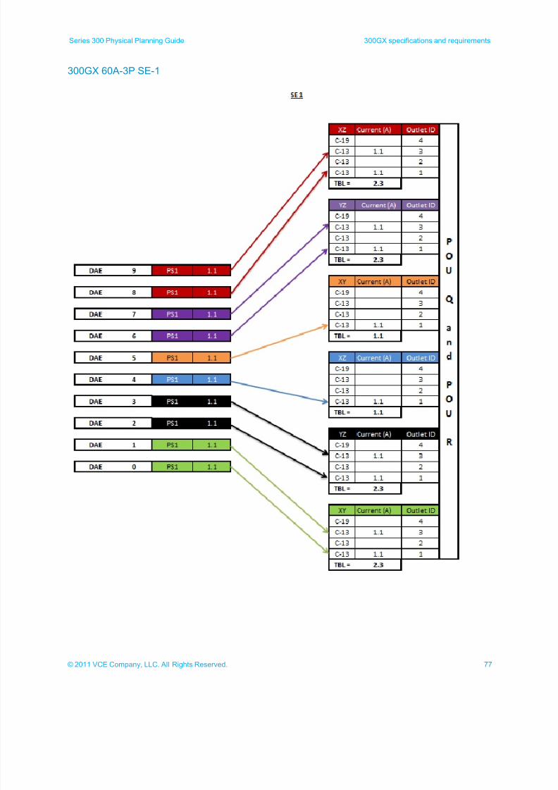
Series 300 Physical Planning Guide 300GX specifications and requirements
300GX 60A-3P SE-1
7/21/2019 VCE Vblock™ Systems 300 Physical Planning Guide (Cisco UCS)
http://slidepdf.com/reader/full/vce-vblock-systems-300-physical-planning-guide-cisco-ucs 78/132
78 © 2011 VCE Company, LLC. All Rights Reserved.
300GX specifications and requirements Series 300 Physical Planning Guide
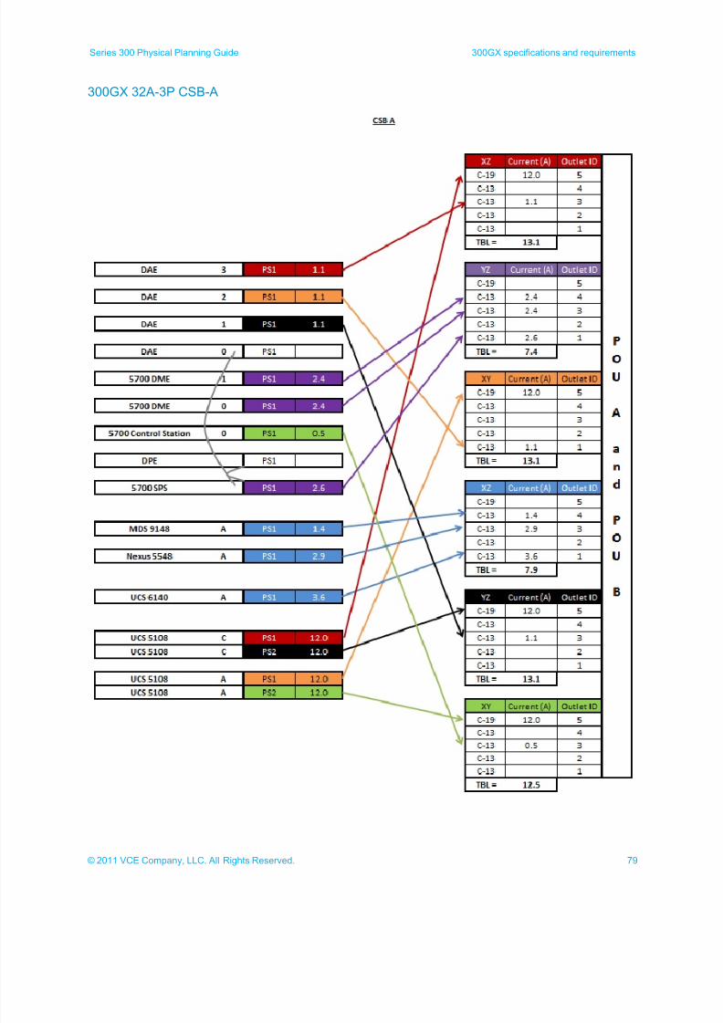
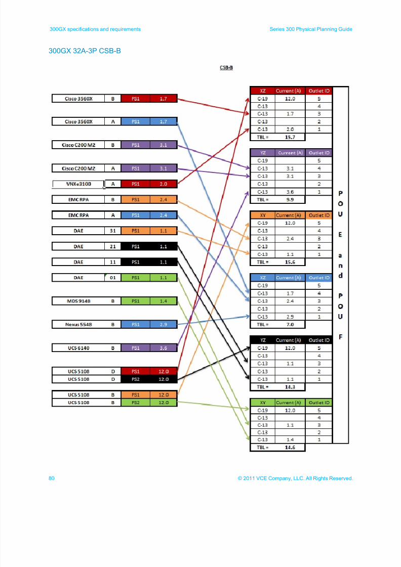
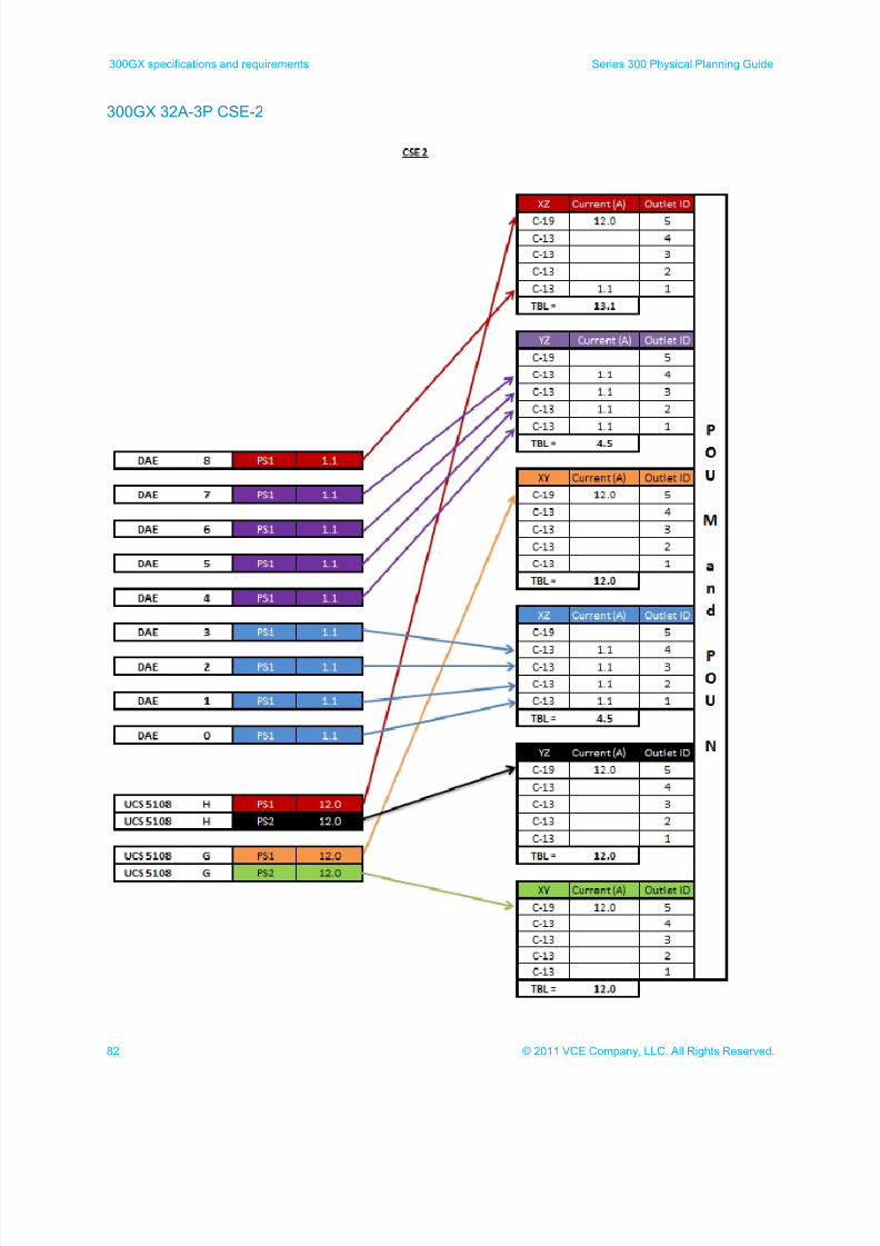
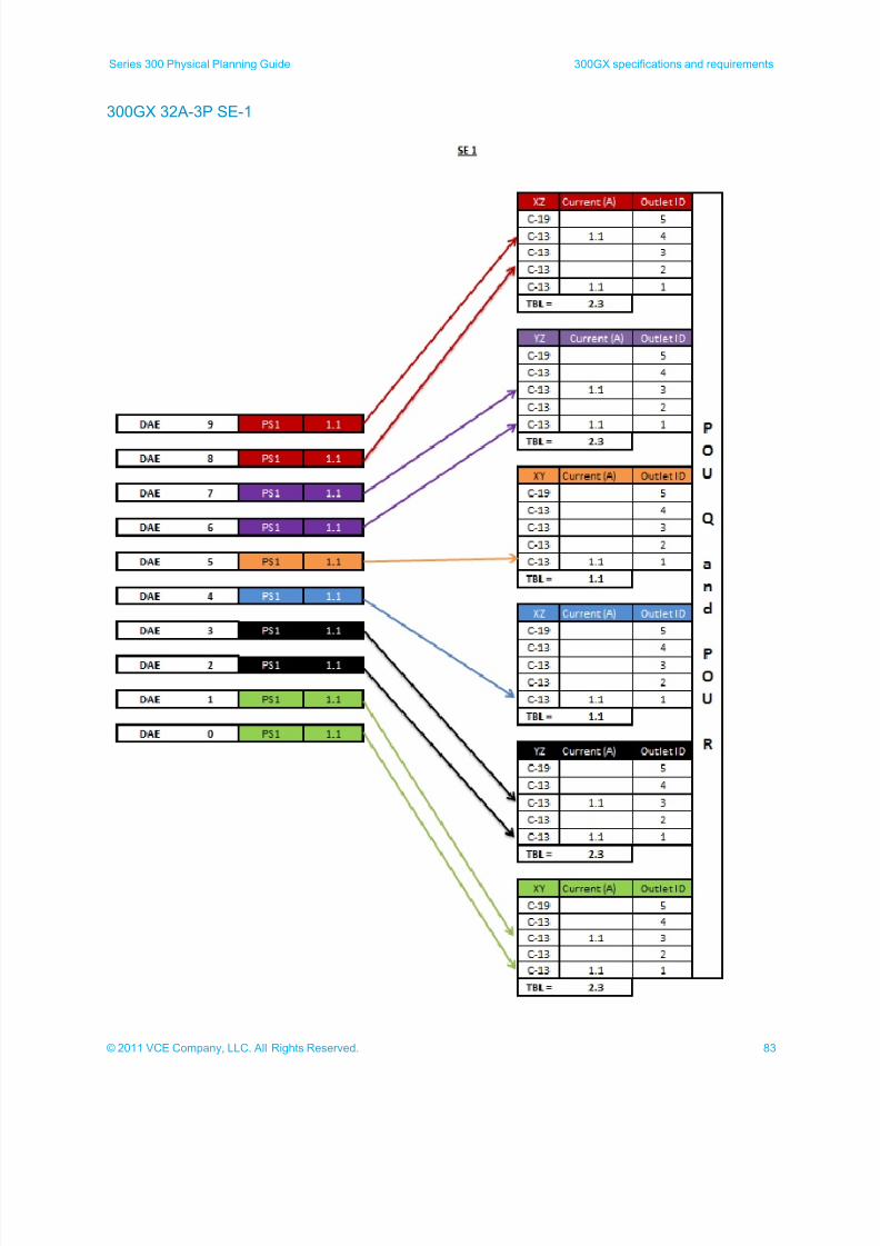
300GX 32A-3P power calculations
The following illustrations show the power calculations used for determining the maximum power used for 32A
3-phase 300GX cabinets
Compute/storage base cabinet A (CSB-A)
Compute/storage base cabinet B (CSB-B)
Compute/storage expansion cabinet 1 (CSE-1)
Compute/storage expansion cabinet 2(CSE-2)
Storage expansion cabinet 1 (SE-1)
Note: Components marked with a gray line (DAEs and DPEs) plug into the standby power supply (5700
SPS) and are not directly included in the power calculations. The standby power supply is used in
these calculations.
7/21/2019 VCE Vblock™ Systems 300 Physical Planning Guide (Cisco UCS)
http://slidepdf.com/reader/full/vce-vblock-systems-300-physical-planning-guide-cisco-ucs 79/132
79© 2011 VCE Company, LLC. All Rights Reserved.
Series 300 Physical Planning Guide 300GX specifications and requirements
300GX 32A-3P CSB-A
7/21/2019 VCE Vblock™ Systems 300 Physical Planning Guide (Cisco UCS)
http://slidepdf.com/reader/full/vce-vblock-systems-300-physical-planning-guide-cisco-ucs 80/132
80 © 2011 VCE Company, LLC. All Rights Reserved.
300GX specifications and requirements Series 300 Physical Planning Guide
300GX 32A-3P CSB-B

7/21/2019 VCE Vblock™ Systems 300 Physical Planning Guide (Cisco UCS)
http://slidepdf.com/reader/full/vce-vblock-systems-300-physical-planning-guide-cisco-ucs 81/132
81© 2011 VCE Company, LLC. All Rights Reserved.
Series 300 Physical Planning Guide 300GX specifications and requirements
300GX 32A-3P CSE-1
7/21/2019 VCE Vblock™ Systems 300 Physical Planning Guide (Cisco UCS)
http://slidepdf.com/reader/full/vce-vblock-systems-300-physical-planning-guide-cisco-ucs 82/132
82 © 2011 VCE Company, LLC. All Rights Reserved.
300GX specifications and requirements Series 300 Physical Planning Guide
300GX 32A-3P CSE-2
7/21/2019 VCE Vblock™ Systems 300 Physical Planning Guide (Cisco UCS)
http://slidepdf.com/reader/full/vce-vblock-systems-300-physical-planning-guide-cisco-ucs 83/132
83© 2011 VCE Company, LLC. All Rights Reserved.
Series 300 Physical Planning Guide 300GX specifications and requirements
300GX 32A-3P SE-1
7/21/2019 VCE Vblock™ Systems 300 Physical Planning Guide (Cisco UCS)
http://slidepdf.com/reader/full/vce-vblock-systems-300-physical-planning-guide-cisco-ucs 84/132
84 © 2011 VCE Company, LLC. All Rights Reserved.
300GX specifications and requirements Series 300 Physical Planning Guide
300GX 30A-3P 60A-1P 16A-3P power calculations
This topic shows the power calculations for 30A-3 phase / 60A-1 phase / 16A-3 phase 300GX cabinets:
Compute/storage base cabinet A (CSB-A) positions 1 and 2
Compute/storage base cabinet A (CSB-A) positions 3 and 4
Compute/storage base cabinet B (CSB-B) positions 1 and 2
Compute/storage base cabinet B (CSB-B) positions 3 and 4
Compute/storage expansion cabinet 1 (CSE-1) positions 1 and 2
Compute/storage expansion cabinet 1 (CSE-1) positions 3 and 4
Compute/storage expansion cabinet 2 (CSE-2) positions 1 and 2
Compute/storage expansion cabinet 2 (CSE-2) positions 3 and 4
Storage expansion cabinet 1 (SE-1) positions 1 and 2
Note: Components marked with a gray line (DAEs and DPEs) plug into the standby power supply (5700
SPS) and are not directly included in the power calculations. The standby power supply is used in
these calculations.
7/21/2019 VCE Vblock™ Systems 300 Physical Planning Guide (Cisco UCS)
http://slidepdf.com/reader/full/vce-vblock-systems-300-physical-planning-guide-cisco-ucs 85/132
85© 2011 VCE Company, LLC. All Rights Reserved.
Series 300 Physical Planning Guide 300GX specifications and requirements
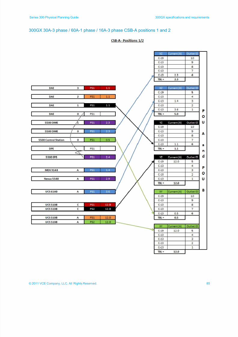
300GX 30A-3 phase / 60A-1 phase / 16A-3 phase CSB-A positions 1 and 2
7/21/2019 VCE Vblock™ Systems 300 Physical Planning Guide (Cisco UCS)
http://slidepdf.com/reader/full/vce-vblock-systems-300-physical-planning-guide-cisco-ucs 86/132
86 © 2011 VCE Company, LLC. All Rights Reserved.
300GX specifications and requirements Series 300 Physical Planning Guide
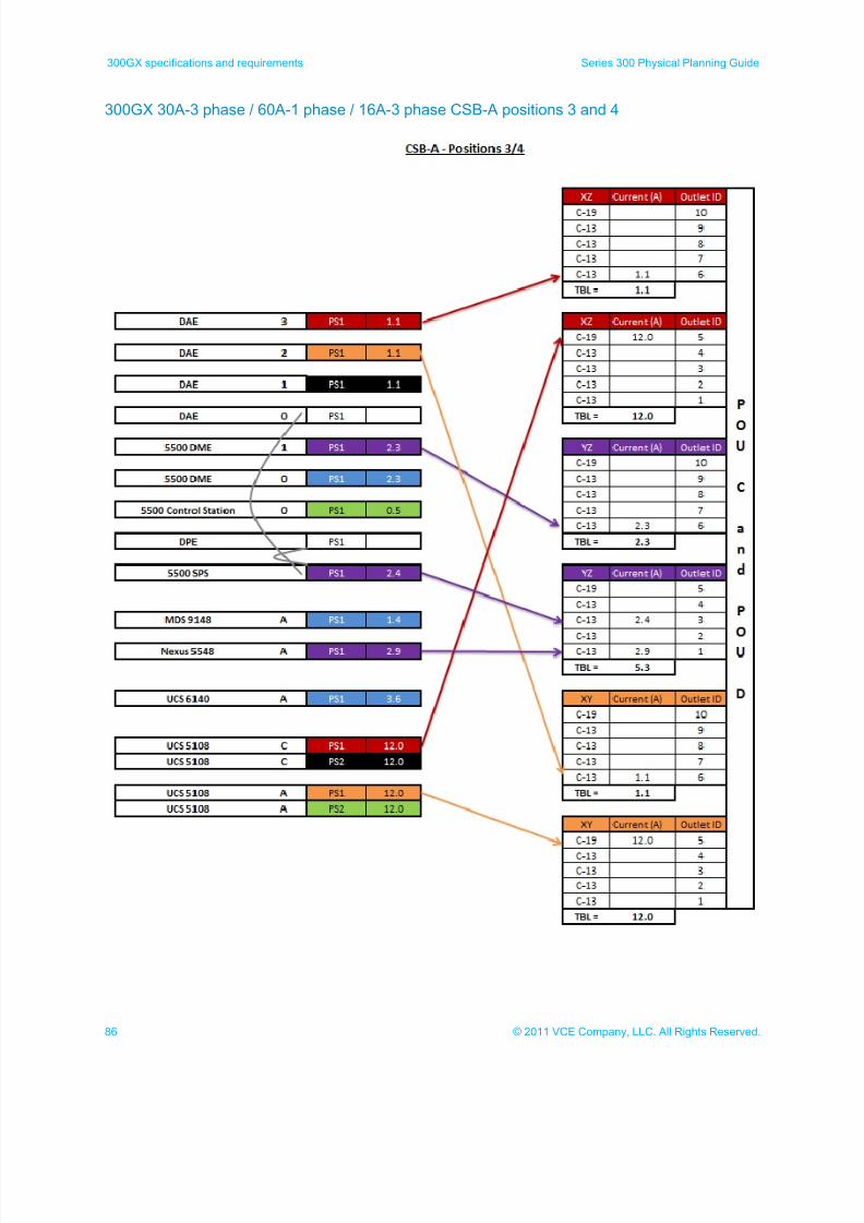
300GX 30A-3 phase / 60A-1 phase / 16A-3 phase CSB-A positions 3 and 4
7/21/2019 VCE Vblock™ Systems 300 Physical Planning Guide (Cisco UCS)
http://slidepdf.com/reader/full/vce-vblock-systems-300-physical-planning-guide-cisco-ucs 87/132
87© 2011 VCE Company, LLC. All Rights Reserved.
Series 300 Physical Planning Guide 300GX specifications and requirements
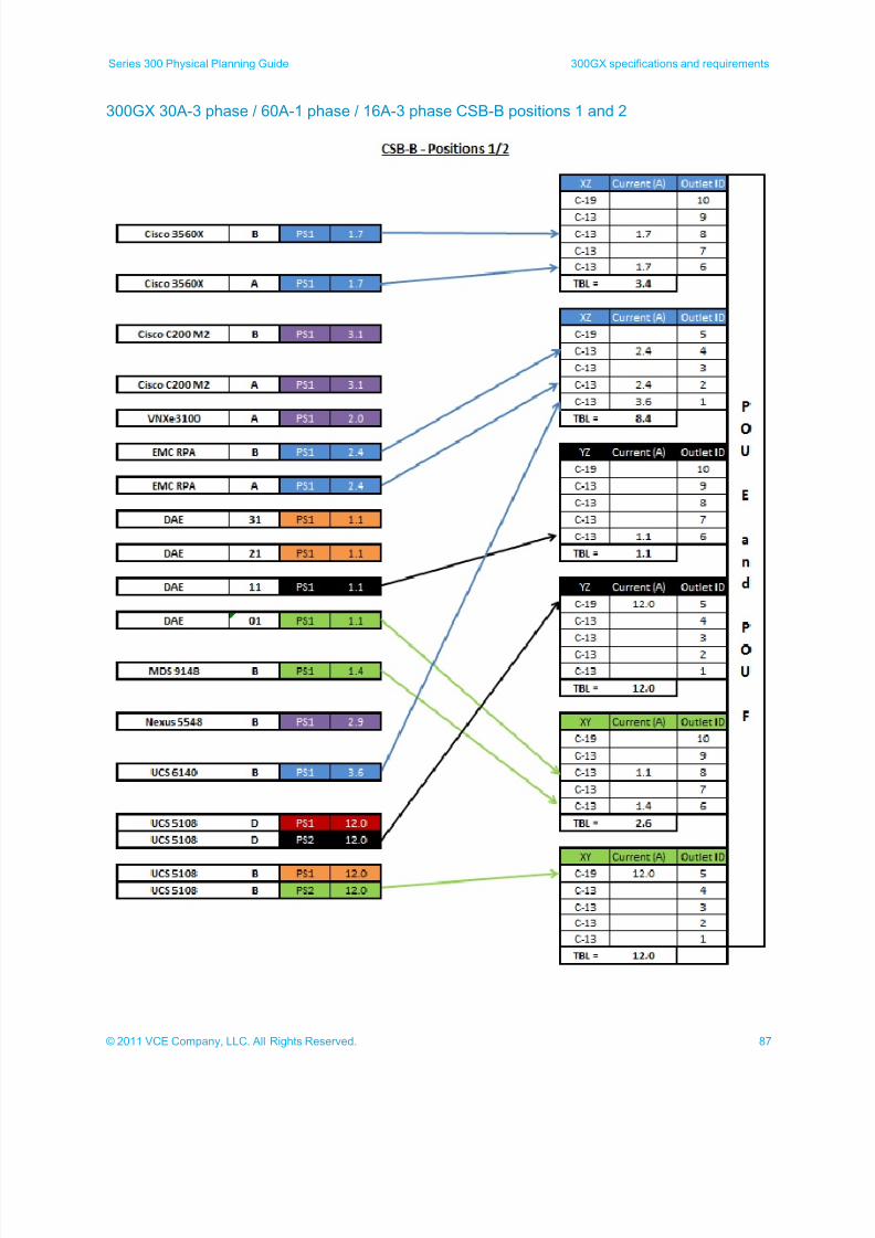
300GX 30A-3 phase / 60A-1 phase / 16A-3 phase CSB-B positions 1 and 2
7/21/2019 VCE Vblock™ Systems 300 Physical Planning Guide (Cisco UCS)
http://slidepdf.com/reader/full/vce-vblock-systems-300-physical-planning-guide-cisco-ucs 88/132
88 © 2011 VCE Company, LLC. All Rights Reserved.
300GX specifications and requirements Series 300 Physical Planning Guide
300GX 30A-3 phase / 60A-1 phase / 16A-3 phase CSB-B positions 3 and 4
7/21/2019 VCE Vblock™ Systems 300 Physical Planning Guide (Cisco UCS)
http://slidepdf.com/reader/full/vce-vblock-systems-300-physical-planning-guide-cisco-ucs 89/132
89© 2011 VCE Company, LLC. All Rights Reserved.
Series 300 Physical Planning Guide 300GX specifications and requirements
300GX 30A-3 phase / 60A-1 phase / 16A-3 phase CSE-1 positions 1 and 2
7/21/2019 VCE Vblock™ Systems 300 Physical Planning Guide (Cisco UCS)
http://slidepdf.com/reader/full/vce-vblock-systems-300-physical-planning-guide-cisco-ucs 90/132
90 © 2011 VCE Company, LLC. All Rights Reserved.
300GX specifications and requirements Series 300 Physical Planning Guide
300GX 30A-3 phase / 60A-1 phase / 16A-3 phase CSE-1 positions 3 and 4
7/21/2019 VCE Vblock™ Systems 300 Physical Planning Guide (Cisco UCS)
http://slidepdf.com/reader/full/vce-vblock-systems-300-physical-planning-guide-cisco-ucs 91/132
91© 2011 VCE Company, LLC. All Rights Reserved.
Series 300 Physical Planning Guide 300GX specifications and requirements
300GX 30A-3 phase / 60A-1 phase / 16A-3 phase CSE-2 positions 1 and 2
7/21/2019 VCE Vblock™ Systems 300 Physical Planning Guide (Cisco UCS)
http://slidepdf.com/reader/full/vce-vblock-systems-300-physical-planning-guide-cisco-ucs 92/132
92 © 2011 VCE Company, LLC. All Rights Reserved.
300GX specifications and requirements Series 300 Physical Planning Guide
300GX 30A-3 phase / 60A-1 phase / 16A-3 phase CSE-2 positions 3 and 4
7/21/2019 VCE Vblock™ Systems 300 Physical Planning Guide (Cisco UCS)
http://slidepdf.com/reader/full/vce-vblock-systems-300-physical-planning-guide-cisco-ucs 93/132
93© 2011 VCE Company, LLC. All Rights Reserved.
Series 300 Physical Planning Guide 300GX specifications and requirements
300GX 30A-3 phase / 60A-1 phase / 16A-3 phase SE-1 positions 1 and 2
7/21/2019 VCE Vblock™ Systems 300 Physical Planning Guide (Cisco UCS)
http://slidepdf.com/reader/full/vce-vblock-systems-300-physical-planning-guide-cisco-ucs 94/132
94 © 2011 VCE Company, LLC. All Rights Reserved.
300HX specifications and requirements Series 300 Physical Planning Guide
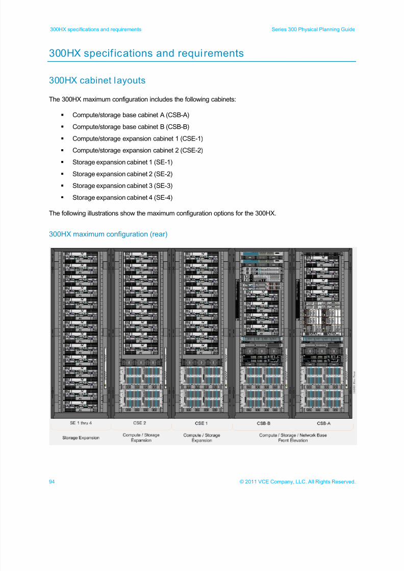
300HX specif ications and requirements
300HX cabinet layouts
The 300HX maximum configuration includes the following cabinets:
Compute/storage base cabinet A (CSB-A)
Compute/storage base cabinet B (CSB-B)
Compute/storage expansion cabinet 1 (CSE-1)
Compute/storage expansion cabinet 2 (CSE-2)
Storage expansion cabinet 1 (SE-1)
Storage expansion cabinet 2 (SE-2)
Storage expansion cabinet 3 (SE-3)
Storage expansion cabinet 4 (SE-4)
The following illustrations show the maximum configuration options for the 300HX.
300HX maximum configuration (rear)
7/21/2019 VCE Vblock™ Systems 300 Physical Planning Guide (Cisco UCS)
http://slidepdf.com/reader/full/vce-vblock-systems-300-physical-planning-guide-cisco-ucs 95/132
95© 2011 VCE Company, LLC. All Rights Reserved.
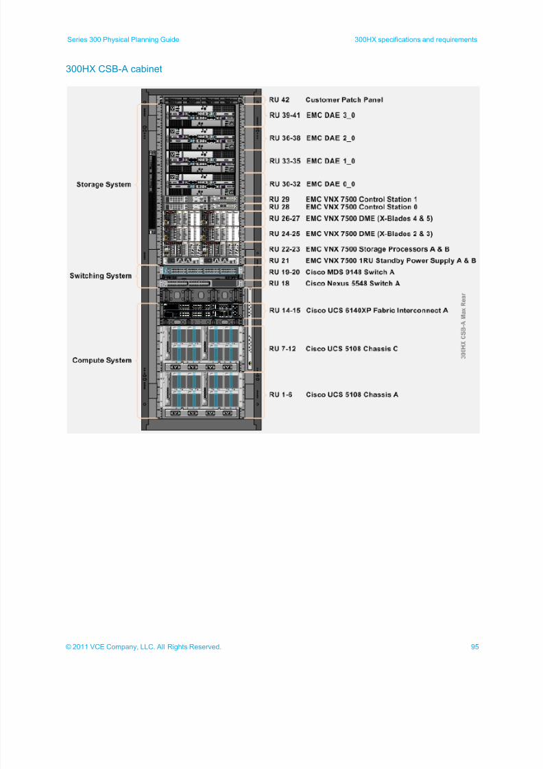
Series 300 Physical Planning Guide 300HX specifications and requirements
300HX CSB-A cabinet
7/21/2019 VCE Vblock™ Systems 300 Physical Planning Guide (Cisco UCS)
http://slidepdf.com/reader/full/vce-vblock-systems-300-physical-planning-guide-cisco-ucs 96/132
96 © 2011 VCE Company, LLC. All Rights Reserved.
300HX specifications and requirements Series 300 Physical Planning Guide
300HX CSB-B cabinet
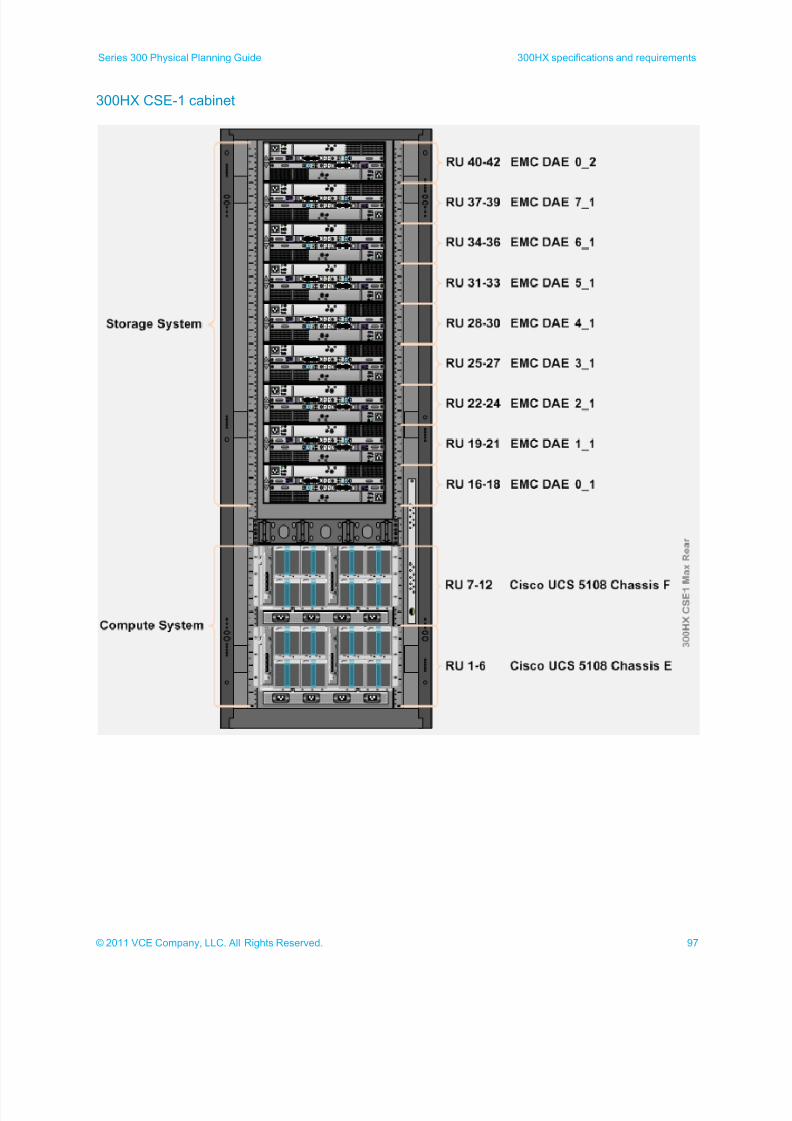
7/21/2019 VCE Vblock™ Systems 300 Physical Planning Guide (Cisco UCS)
http://slidepdf.com/reader/full/vce-vblock-systems-300-physical-planning-guide-cisco-ucs 97/132
97© 2011 VCE Company, LLC. All Rights Reserved.
Series 300 Physical Planning Guide 300HX specifications and requirements
300HX CSE-1 cabinet
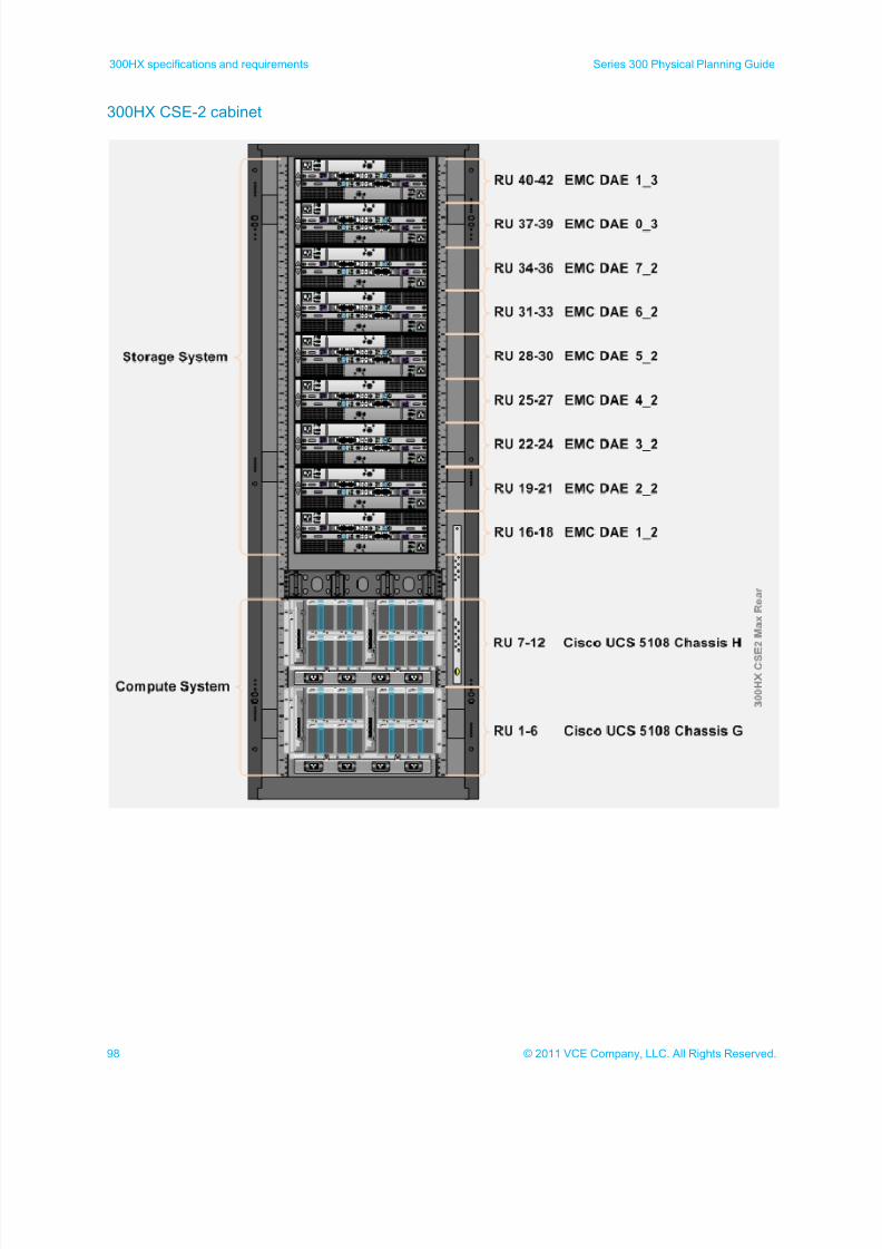
7/21/2019 VCE Vblock™ Systems 300 Physical Planning Guide (Cisco UCS)
http://slidepdf.com/reader/full/vce-vblock-systems-300-physical-planning-guide-cisco-ucs 98/132
98 © 2011 VCE Company, LLC. All Rights Reserved.
300HX specifications and requirements Series 300 Physical Planning Guide
300HX CSE-2 cabinet
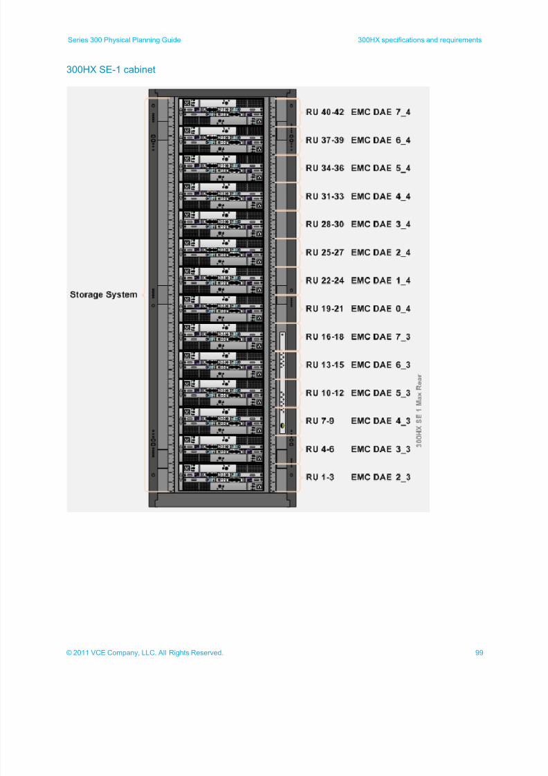
7/21/2019 VCE Vblock™ Systems 300 Physical Planning Guide (Cisco UCS)
http://slidepdf.com/reader/full/vce-vblock-systems-300-physical-planning-guide-cisco-ucs 99/132
99© 2011 VCE Company, LLC. All Rights Reserved.
Series 300 Physical Planning Guide 300HX specifications and requirements
300HX SE-1 cabinet
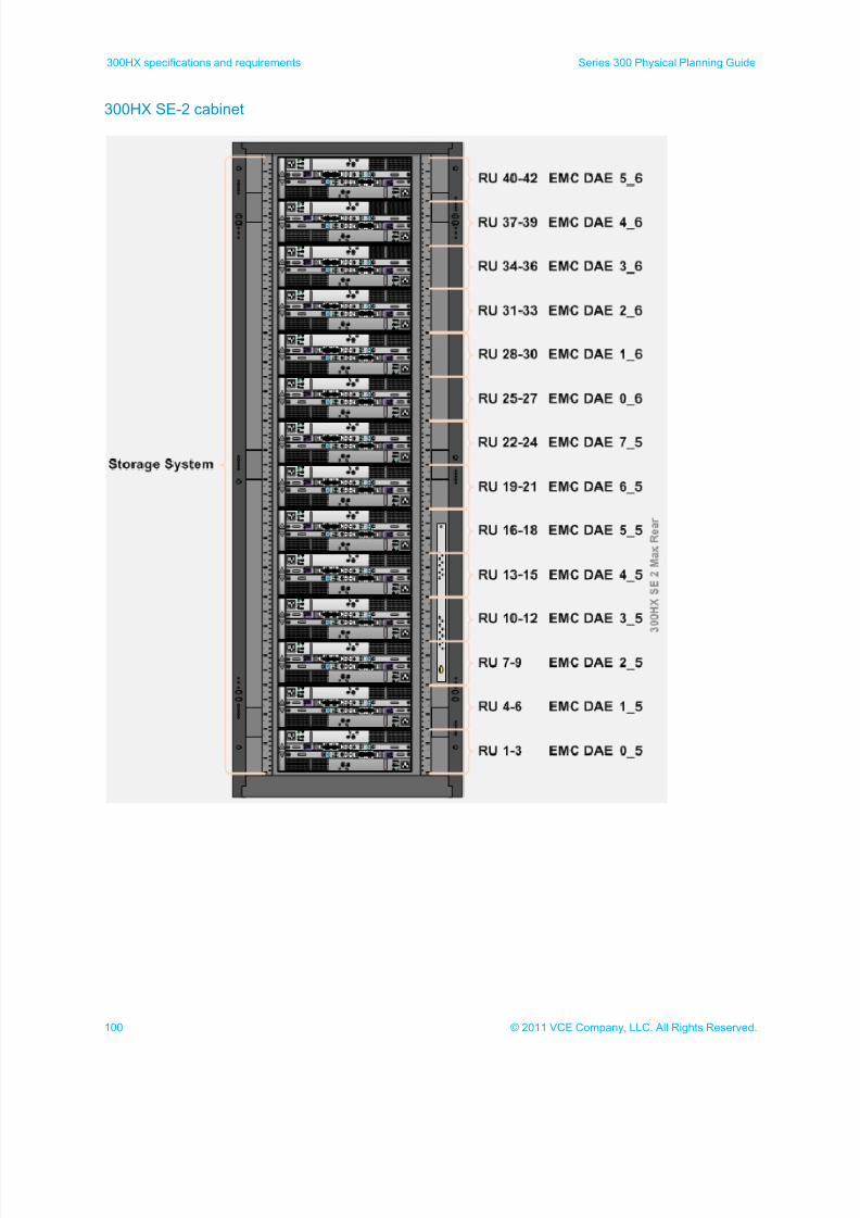
7/21/2019 VCE Vblock™ Systems 300 Physical Planning Guide (Cisco UCS)
http://slidepdf.com/reader/full/vce-vblock-systems-300-physical-planning-guide-cisco-ucs 100/132
100 © 2011 VCE Company, LLC. All Rights Reserved.
300HX specifications and requirements Series 300 Physical Planning Guide
300HX SE-2 cabinet
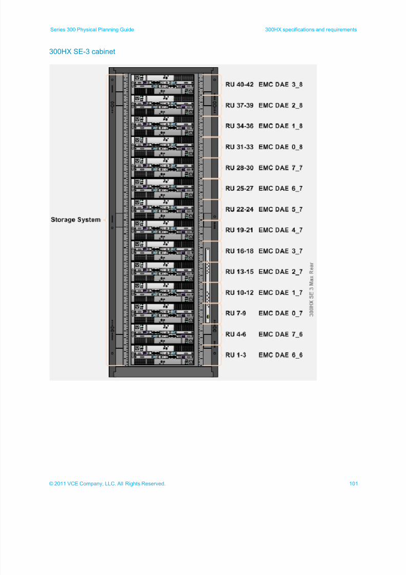
7/21/2019 VCE Vblock™ Systems 300 Physical Planning Guide (Cisco UCS)
http://slidepdf.com/reader/full/vce-vblock-systems-300-physical-planning-guide-cisco-ucs 101/132
101© 2011 VCE Company, LLC. All Rights Reserved.
Series 300 Physical Planning Guide 300HX specifications and requirements
300HX SE-3 cabinet
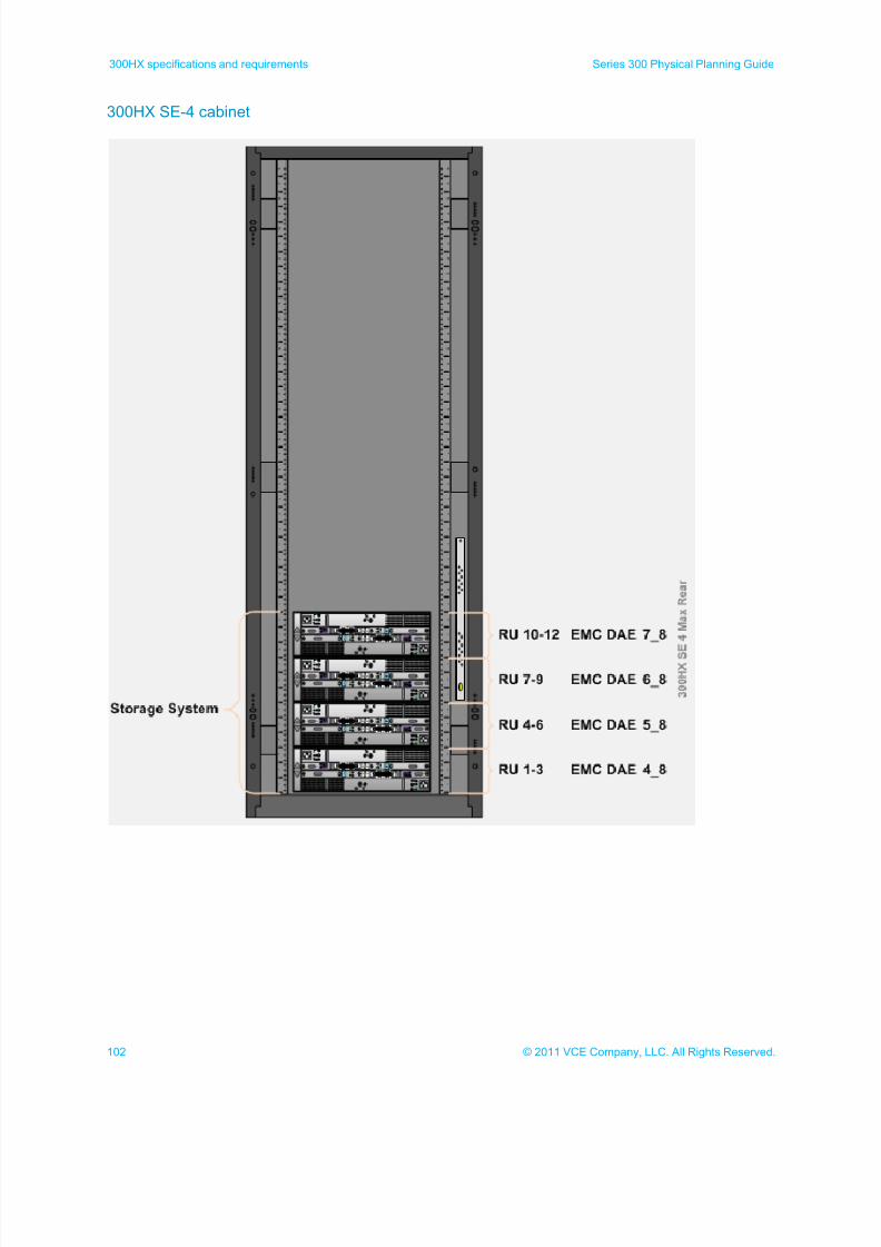
7/21/2019 VCE Vblock™ Systems 300 Physical Planning Guide (Cisco UCS)
http://slidepdf.com/reader/full/vce-vblock-systems-300-physical-planning-guide-cisco-ucs 102/132
102 © 2011 VCE Company, LLC. All Rights Reserved.
300HX specifications and requirements Series 300 Physical Planning Guide
300HX SE-4 cabinet
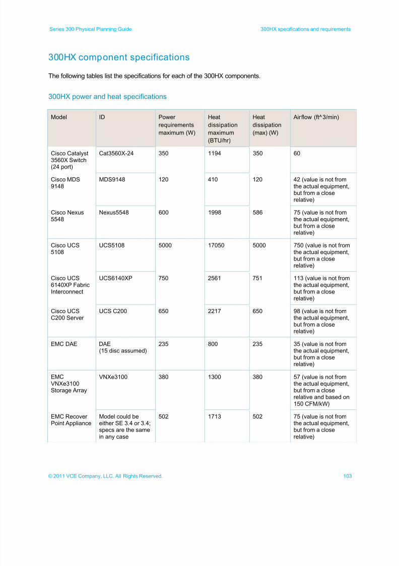
7/21/2019 VCE Vblock™ Systems 300 Physical Planning Guide (Cisco UCS)
http://slidepdf.com/reader/full/vce-vblock-systems-300-physical-planning-guide-cisco-ucs 103/132
103© 2011 VCE Company, LLC. All Rights Reserved.
Series 300 Physical Planning Guide 300HX specifications and requirements
300HX component specifications
The following tables list the specifications for each of the 300HX components.
300HX power and heat specifications
Model ID Power
requirements
maximum (W)
Heat
dissipation
maximum
(BTU/hr)
Heat
dissipation
(max) (W)
Airflow (ft^3/min)
Cisco Catalyst3560X Switch(24 port)
Cat3560X-24 350 1194 350 60
Cisco MDS9148
MDS9148 120 410 120 42 (value is not fromthe actual equipment,but from a close
relative)
Cisco Nexus5548
Nexus5548 600 1998 586 75 (value is not fromthe actual equipment,but from a closerelative)
Cisco UCS5108
UCS5108 5000 17050 5000 750 (value is not fromthe actual equipment,but from a closerelative)
Cisco UCS6140XP FabricInterconnect
UCS6140XP 750 2561 751 113 (value is not fromthe actual equipment,but from a close
relative)
Cisco UCSC200 Server
UCS C200 650 2217 650 98 (value is not fromthe actual equipment,but from a closerelative)
EMC DAE DAE(15 disc assumed)
235 800 235 35 (value is not fromthe actual equipment,but from a closerelative)
EMCVNXe3100Storage Array
VNXe3100 380 1300 380 57 (value is not fromthe actual equipment,but from a close
relative and based on150 CFM/kW)
EMC RecoverPoint Appliance
Model could beeither SE 3.4 or 3.4;specs are the samein any case
502 1713 502 75 (value is not fromthe actual equipment,but from a closerelative)
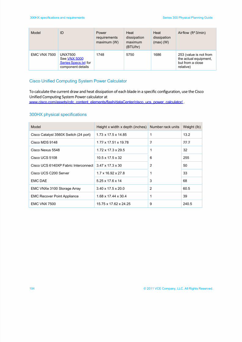
7/21/2019 VCE Vblock™ Systems 300 Physical Planning Guide (Cisco UCS)
http://slidepdf.com/reader/full/vce-vblock-systems-300-physical-planning-guide-cisco-ucs 104/132
104 © 2011 VCE Company, LLC. All Rights Reserved.
300HX specifications and requirements Series 300 Physical Planning Guide
Model ID Power
requirements
maximum (W)
Heat
dissipation
maximum
(BTU/hr)
Heat
dissipation
(max) (W)
Airflow (ft^3/min)
EMC VNX 7500 UNX7500
See VNX 5000Series Specs.txt forcomponent details
1748 5750 1686 253 (value is not from
the actual equipment,but from a closerelative)
Cisco Unified Computing System Power Calculator
To calculate the current draw and heat dissipation of each blade in a specific configuration, use the Cisco
Unified Computing System Power calculator at
www.cisco.com/assets/cdc_content_elements/flash/dataCenter/cisco_ucs_power_calculator/ .
300HX physical specifications
Model Height x width x depth (inches) Number rack units Weight (lb)
Cisco Catalyst 3560X Switch (24 port) 1.73 x 17.5 x 14.85 1 13.2
Cisco MDS 9148 1.72 x 17.51 x 19.78 2 22.2
Cisco Nexus 5548 1.72 x 17.3 x 29.5 1 32
Cisco UCS 5108 10.5 x 17.5 x 32 6 255
Cisco UCS 6140XP Fabric Interconnect 3.47 x 17.3 x 30 2 50
Cisco UCS C200 Server 1.7 x 16.92 x 27.8 1 33
EMC DAE 5.25 x 17.6 x 14 3 68
EMC VNXe 3100 Storage Array 3.40 x 17.5 x 20.0 2 60.5
EMC Recover Point Appliance 1.68 x 17.44 x 30.4 1 39
EMC VNX 7500 15.75 x 17.62 x 24.25 9 240.5
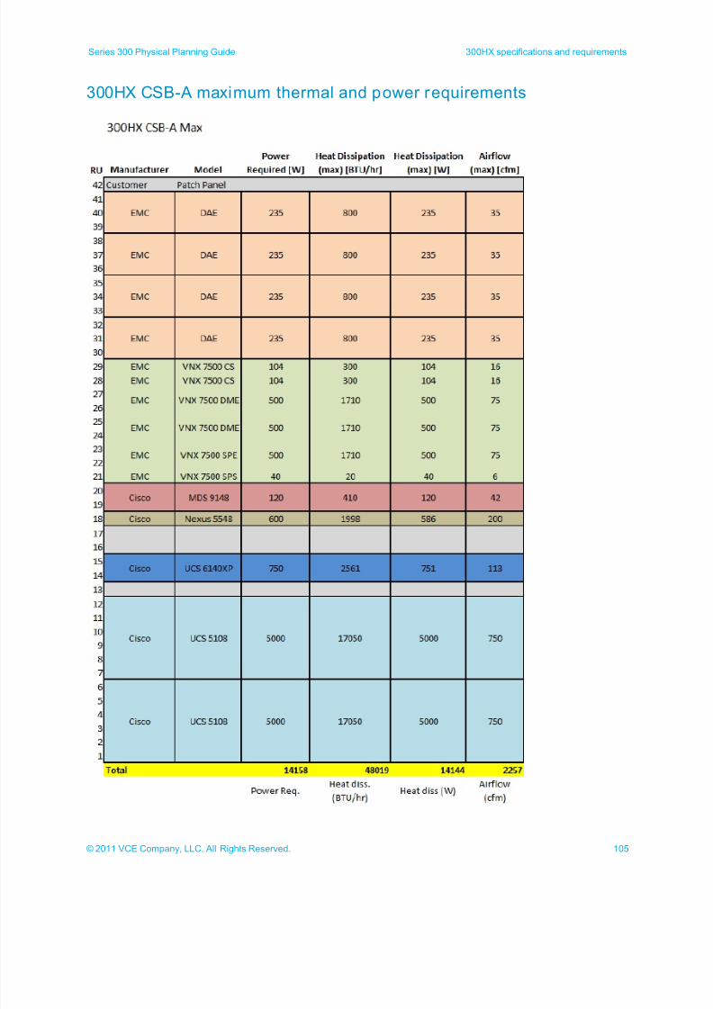
7/21/2019 VCE Vblock™ Systems 300 Physical Planning Guide (Cisco UCS)
http://slidepdf.com/reader/full/vce-vblock-systems-300-physical-planning-guide-cisco-ucs 105/132
105© 2011 VCE Company, LLC. All Rights Reserved.
Series 300 Physical Planning Guide 300HX specifications and requirements
300HX CSB-A maximum thermal and power requirements
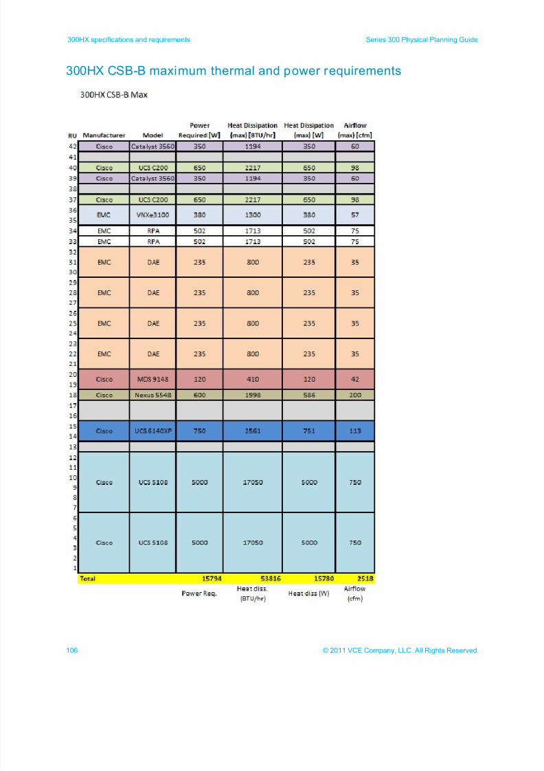
7/21/2019 VCE Vblock™ Systems 300 Physical Planning Guide (Cisco UCS)
http://slidepdf.com/reader/full/vce-vblock-systems-300-physical-planning-guide-cisco-ucs 106/132
106 © 2011 VCE Company, LLC. All Rights Reserved.
300HX specifications and requirements Series 300 Physical Planning Guide
300HX CSB-B maximum thermal and power requirements
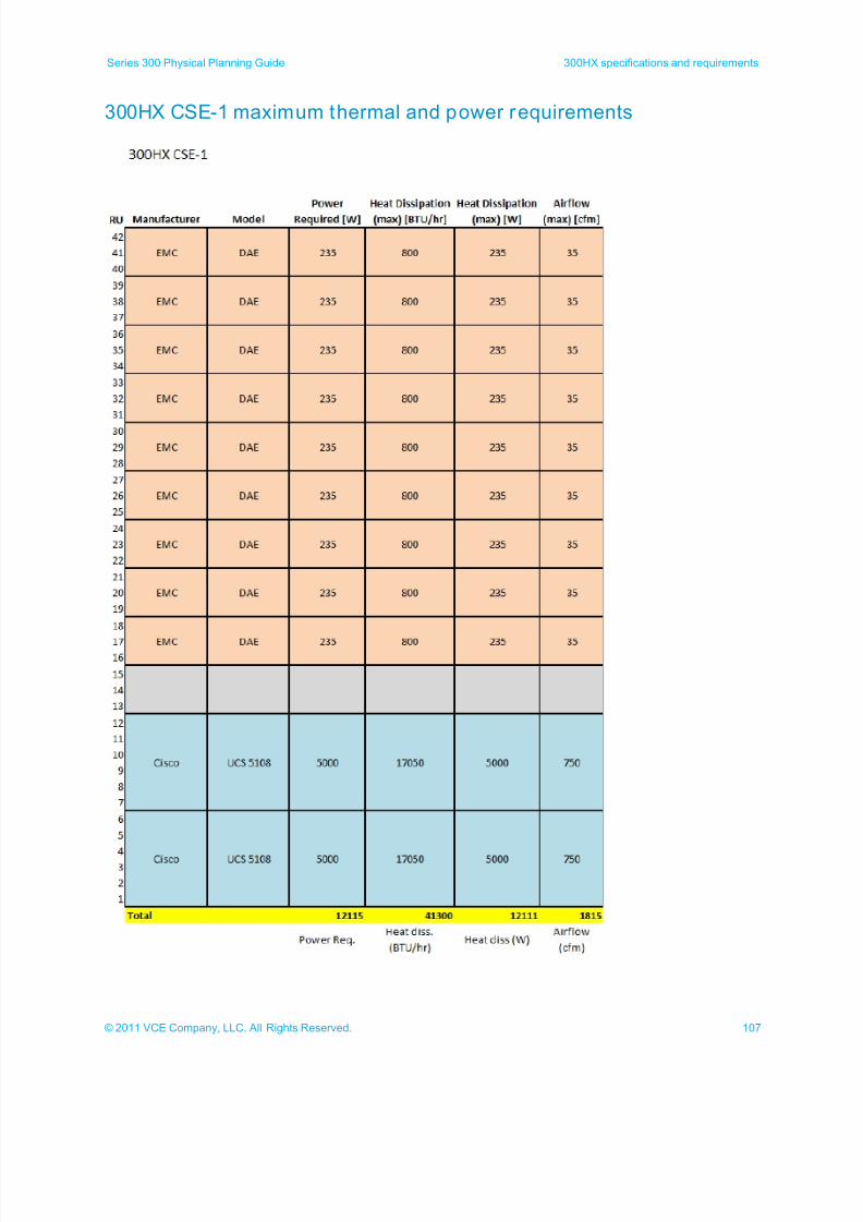
7/21/2019 VCE Vblock™ Systems 300 Physical Planning Guide (Cisco UCS)
http://slidepdf.com/reader/full/vce-vblock-systems-300-physical-planning-guide-cisco-ucs 107/132
107© 2011 VCE Company, LLC. All Rights Reserved.
Series 300 Physical Planning Guide 300HX specifications and requirements
300HX CSE-1 maximum thermal and power requirements
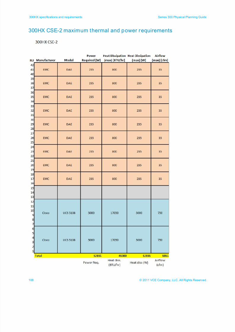
7/21/2019 VCE Vblock™ Systems 300 Physical Planning Guide (Cisco UCS)
http://slidepdf.com/reader/full/vce-vblock-systems-300-physical-planning-guide-cisco-ucs 108/132
108 © 2011 VCE Company, LLC. All Rights Reserved.
300HX specifications and requirements Series 300 Physical Planning Guide
300HX CSE-2 maximum thermal and power requirements
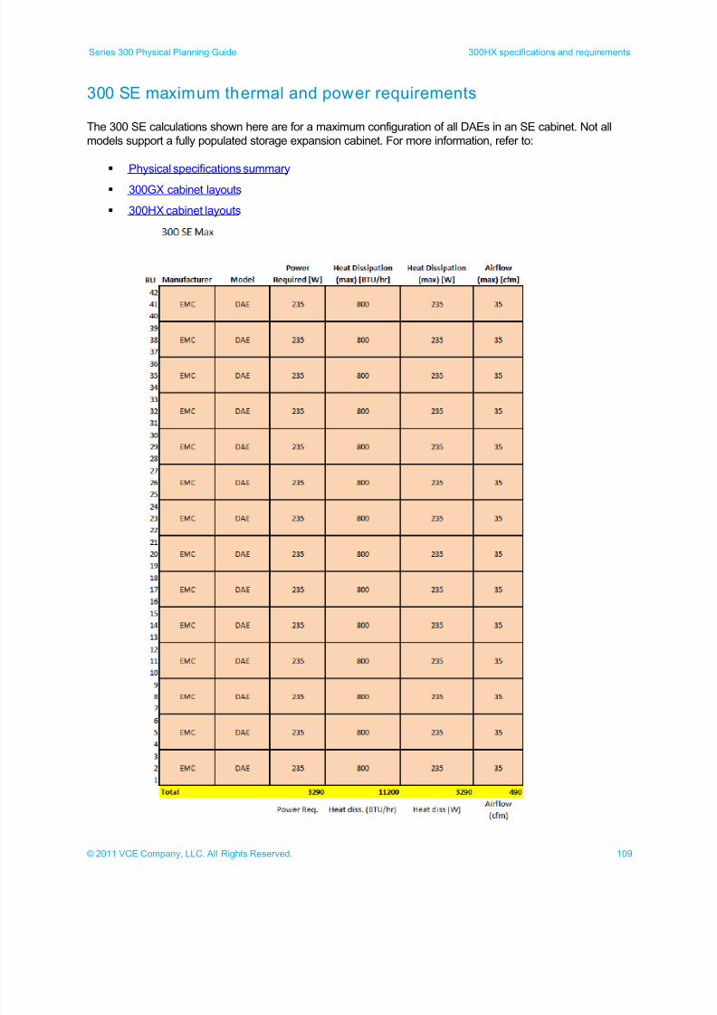
7/21/2019 VCE Vblock™ Systems 300 Physical Planning Guide (Cisco UCS)
http://slidepdf.com/reader/full/vce-vblock-systems-300-physical-planning-guide-cisco-ucs 109/132
109© 2011 VCE Company, LLC. All Rights Reserved.
Series 300 Physical Planning Guide 300HX specifications and requirements
300 SE maximum thermal and power requirements
The 300 SE calculations shown here are for a maximum configuration of all DAEs in an SE cabinet. Not all
models support a fully populated storage expansion cabinet. For more information, refer to:
Physical specifications summary
300GX cabinet layouts
300HX cabinet layouts
7/21/2019 VCE Vblock™ Systems 300 Physical Planning Guide (Cisco UCS)
http://slidepdf.com/reader/full/vce-vblock-systems-300-physical-planning-guide-cisco-ucs 110/132
110 © 2011 VCE Company, LLC. All Rights Reserved.
300HX specifications and requirements Series 300 Physical Planning Guide
300HX 60A-3P power calculations
The following illustrations show the power calculations used for determining the maximum power used for 60A
3-phase 300HX cabinets.
Compute storage base cabinet A (CSB-A)
Compute storage base cabinet B (CSB-B)
Compute storage expansion cabinet 1 (CSE-1)
Compute storage expansion cabinet 2 (CSE-2)
Storage expansion cabinet 1 through 4 (SE-1 through SE-4)
Note: Components marked with a gray line (DAEs and DPEs) plug into the standby power supply (7500
SPS) and are not directly included in the power calculations. The standby power supply is used in
these calculations.
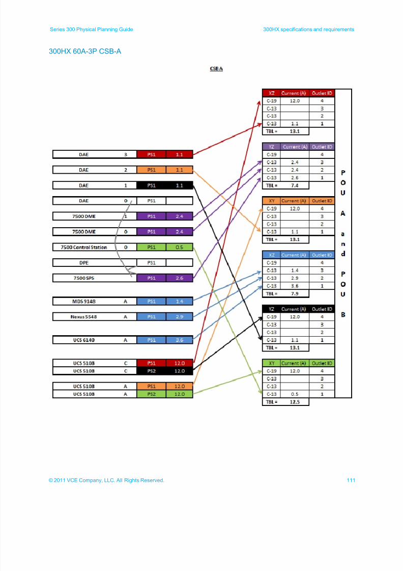
7/21/2019 VCE Vblock™ Systems 300 Physical Planning Guide (Cisco UCS)
http://slidepdf.com/reader/full/vce-vblock-systems-300-physical-planning-guide-cisco-ucs 111/132
111© 2011 VCE Company, LLC. All Rights Reserved.
Series 300 Physical Planning Guide 300HX specifications and requirements
300HX 60A-3P CSB-A
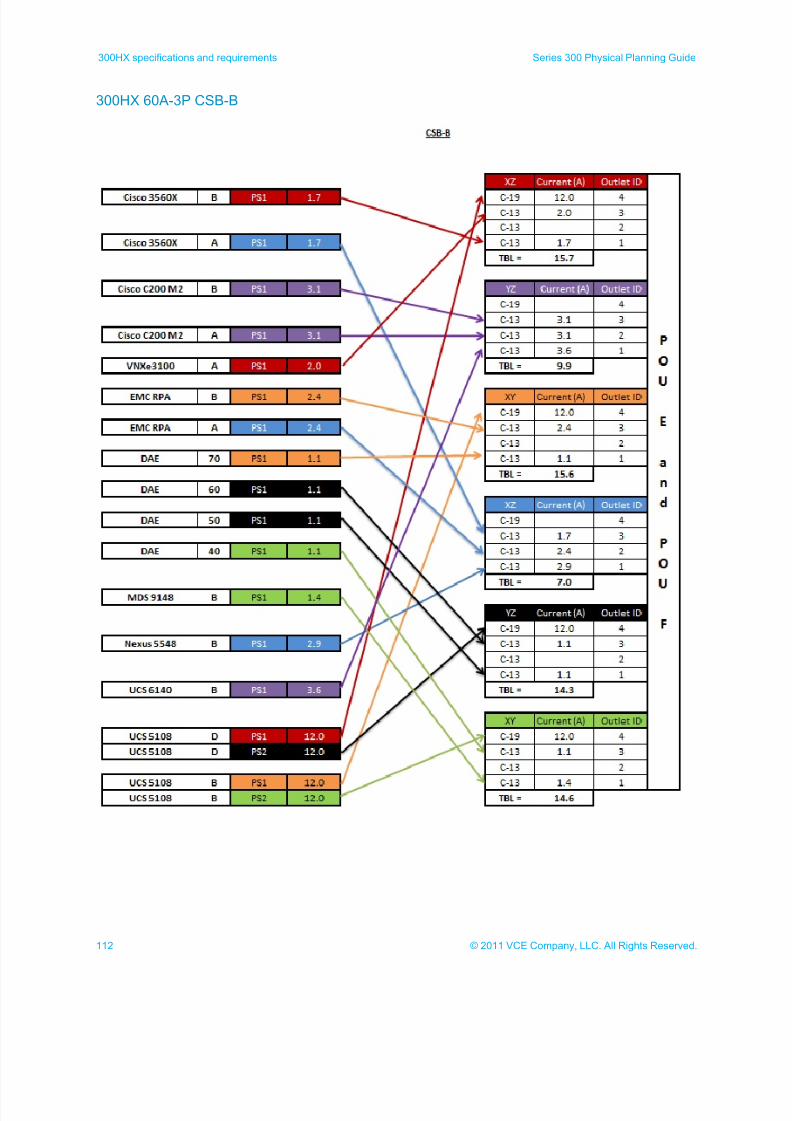
7/21/2019 VCE Vblock™ Systems 300 Physical Planning Guide (Cisco UCS)
http://slidepdf.com/reader/full/vce-vblock-systems-300-physical-planning-guide-cisco-ucs 112/132
112 © 2011 VCE Company, LLC. All Rights Reserved.
300HX specifications and requirements Series 300 Physical Planning Guide
300HX 60A-3P CSB-B
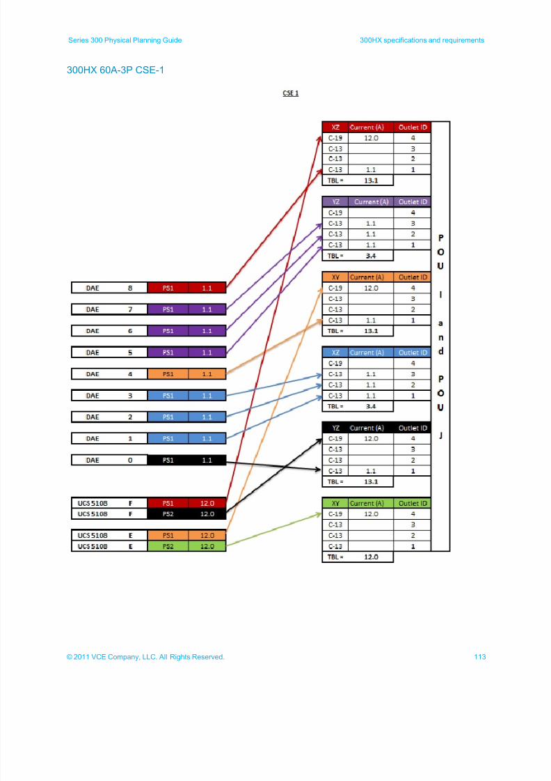
7/21/2019 VCE Vblock™ Systems 300 Physical Planning Guide (Cisco UCS)
http://slidepdf.com/reader/full/vce-vblock-systems-300-physical-planning-guide-cisco-ucs 113/132
113© 2011 VCE Company, LLC. All Rights Reserved.
Series 300 Physical Planning Guide 300HX specifications and requirements
300HX 60A-3P CSE-1
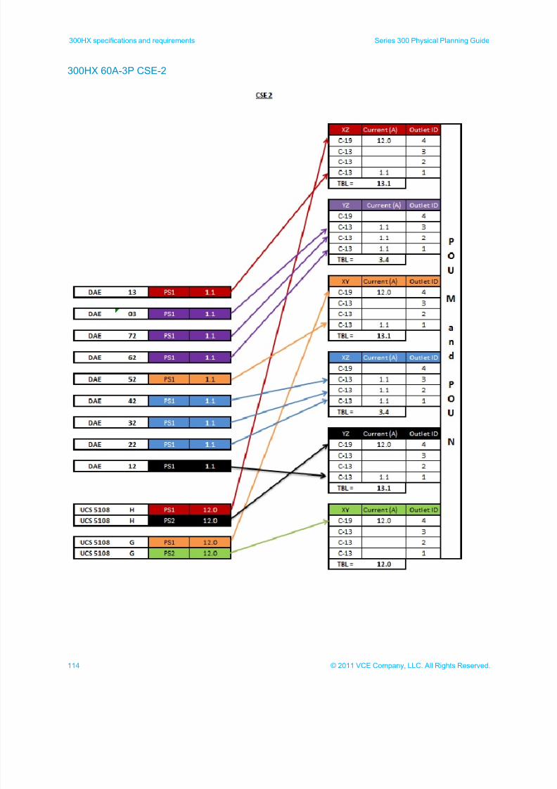
7/21/2019 VCE Vblock™ Systems 300 Physical Planning Guide (Cisco UCS)
http://slidepdf.com/reader/full/vce-vblock-systems-300-physical-planning-guide-cisco-ucs 114/132
114 © 2011 VCE Company, LLC. All Rights Reserved.
300HX specifications and requirements Series 300 Physical Planning Guide
300HX 60A-3P CSE-2
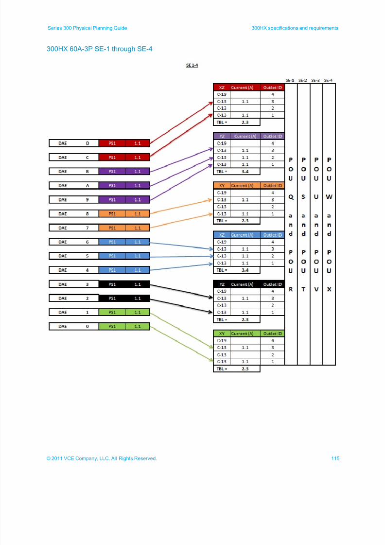
7/21/2019 VCE Vblock™ Systems 300 Physical Planning Guide (Cisco UCS)
http://slidepdf.com/reader/full/vce-vblock-systems-300-physical-planning-guide-cisco-ucs 115/132
115© 2011 VCE Company, LLC. All Rights Reserved.
Series 300 Physical Planning Guide 300HX specifications and requirements
300HX 60A-3P SE-1 through SE-4
7/21/2019 VCE Vblock™ Systems 300 Physical Planning Guide (Cisco UCS)
http://slidepdf.com/reader/full/vce-vblock-systems-300-physical-planning-guide-cisco-ucs 116/132
116 © 2011 VCE Company, LLC. All Rights Reserved.
300HX specifications and requirements Series 300 Physical Planning Guide
300HX 32A-3P power calculations
The following illustrations show the power calculations used for determining the maximum power used for 32A
3-phase 300HX cabinets.
Compute storage base cabinet A (CSB-A)
Compute storage base cabinet B (CSB-B)
Compute storage expansion cabinet 1 (CSE-1)
Compute storage expansion cabinet 2 (CSE-2)
Storage expansion cabinet 1 through 4 (SE-1 through SE-4)
Note: Components marked with a gray line (DAEs and DPEs) plug into the standby power supply (7500
SPS) and are not directly included in the power calculations. The standby power supply is used in
these calculations.
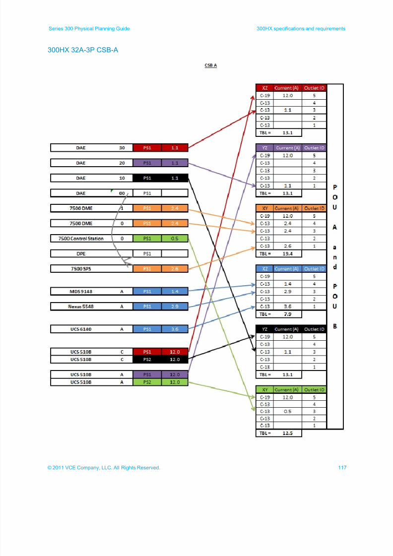
7/21/2019 VCE Vblock™ Systems 300 Physical Planning Guide (Cisco UCS)
http://slidepdf.com/reader/full/vce-vblock-systems-300-physical-planning-guide-cisco-ucs 117/132
117© 2011 VCE Company, LLC. All Rights Reserved.
Series 300 Physical Planning Guide 300HX specifications and requirements
300HX 32A-3P CSB-A

7/21/2019 VCE Vblock™ Systems 300 Physical Planning Guide (Cisco UCS)
http://slidepdf.com/reader/full/vce-vblock-systems-300-physical-planning-guide-cisco-ucs 118/132
118 © 2011 VCE Company, LLC. All Rights Reserved.
300HX specifications and requirements Series 300 Physical Planning Guide
300HX 32A-3P CSB-B
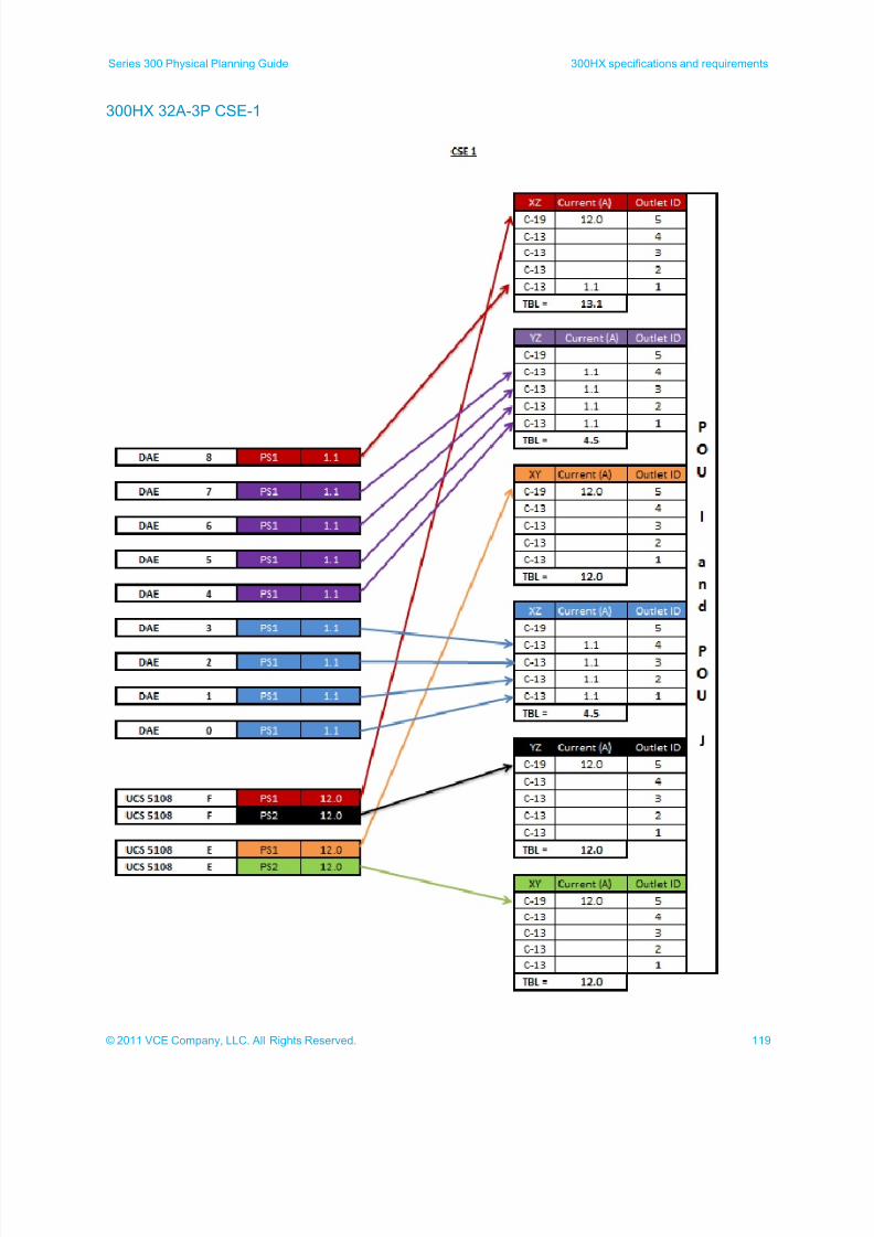
7/21/2019 VCE Vblock™ Systems 300 Physical Planning Guide (Cisco UCS)
http://slidepdf.com/reader/full/vce-vblock-systems-300-physical-planning-guide-cisco-ucs 119/132
119© 2011 VCE Company, LLC. All Rights Reserved.
Series 300 Physical Planning Guide 300HX specifications and requirements
300HX 32A-3P CSE-1
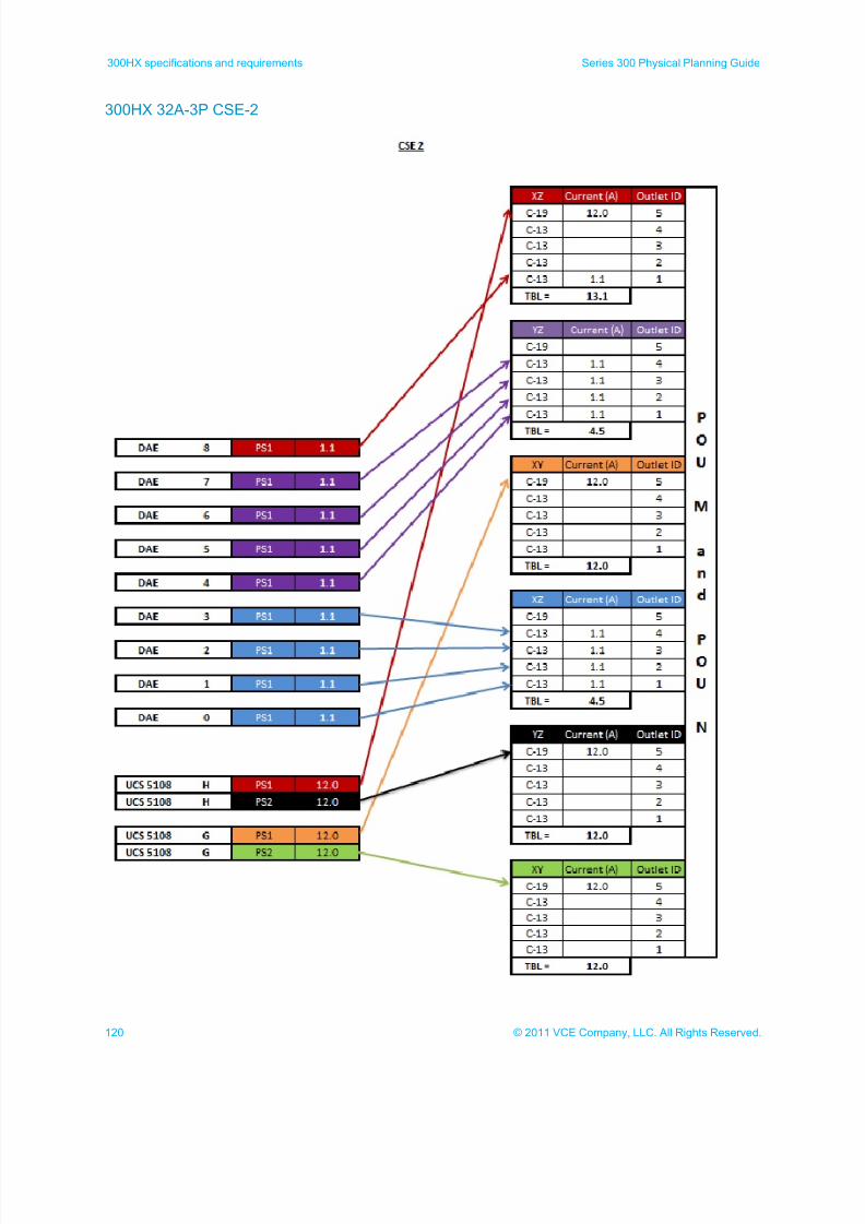
7/21/2019 VCE Vblock™ Systems 300 Physical Planning Guide (Cisco UCS)
http://slidepdf.com/reader/full/vce-vblock-systems-300-physical-planning-guide-cisco-ucs 120/132
120 © 2011 VCE Company, LLC. All Rights Reserved.
300HX specifications and requirements Series 300 Physical Planning Guide
300HX 32A-3P CSE-2
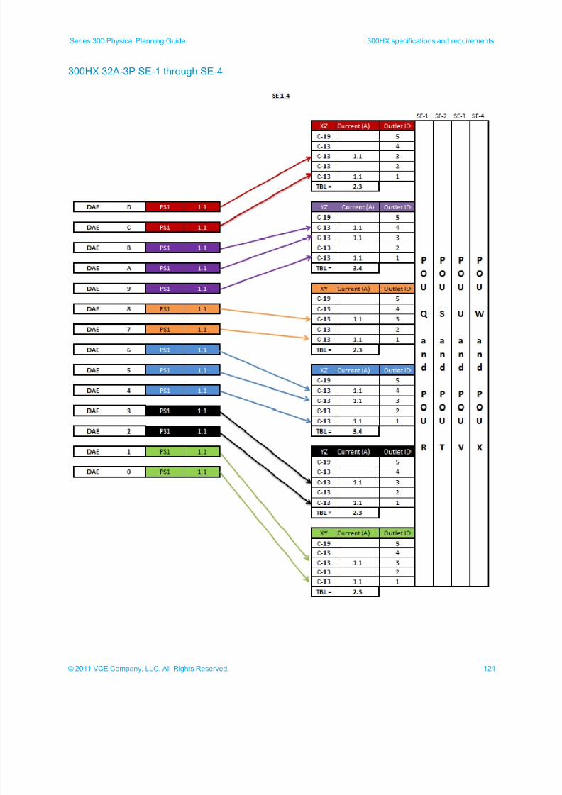
7/21/2019 VCE Vblock™ Systems 300 Physical Planning Guide (Cisco UCS)
http://slidepdf.com/reader/full/vce-vblock-systems-300-physical-planning-guide-cisco-ucs 121/132
121© 2011 VCE Company, LLC. All Rights Reserved.
Series 300 Physical Planning Guide 300HX specifications and requirements
300HX 32A-3P SE-1 through SE-4
7/21/2019 VCE Vblock™ Systems 300 Physical Planning Guide (Cisco UCS)
http://slidepdf.com/reader/full/vce-vblock-systems-300-physical-planning-guide-cisco-ucs 122/132
122 © 2011 VCE Company, LLC. All Rights Reserved.
300HX specifications and requirements Series 300 Physical Planning Guide
300HX 30A-3P 60A-1P 16A-3P power calculations
This topic shows the power calculations for 30A-3 phase / 60A-1 phase / 16A-3 phase 300HX cabinets:
Compute storage base cabinet A (CSB-A) positions 1 and 2
Compute storage base cabinet A (CSB-A) positions 3 and 4
Compute storage base cabinet B (CSB-B) positions 1 and 2
Compute storage base cabinet B (CSB-B) positions 3 and 4
Compute storage expansion cabinet 1 (CSE-1) positions 1 and 2
Compute storage expansion cabinet 1 (CSE-1) positions 3 and 4
Compute storage expansion cabinet 2 (CSE-2) positions 1 and 2
Compute storage expansion cabinet 2 (CSE-2) positions 3 and 4
Storage expansion cabinets 1 through 4 (SE-1 through SE-4) positions 1 and 2
Note: Components marked with a gray line (DAEs and DPEs) plug into the standby power supply (7500
SPS) and are not directly included in the power calculations. The standby power supply is used in
these calculations.
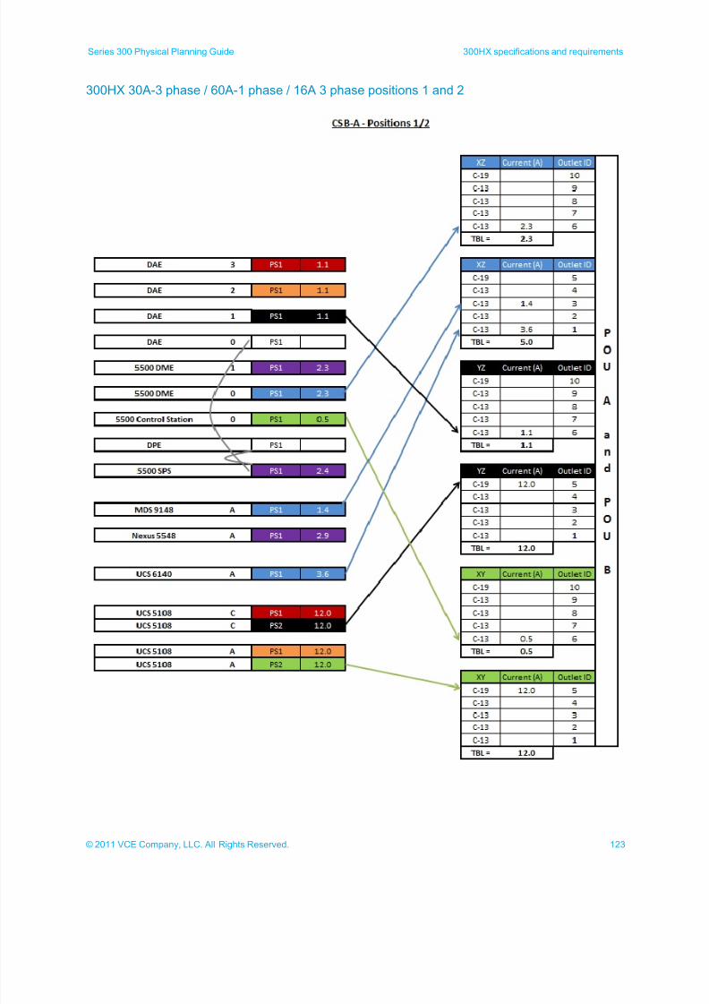
7/21/2019 VCE Vblock™ Systems 300 Physical Planning Guide (Cisco UCS)
http://slidepdf.com/reader/full/vce-vblock-systems-300-physical-planning-guide-cisco-ucs 123/132
123© 2011 VCE Company, LLC. All Rights Reserved.
Series 300 Physical Planning Guide 300HX specifications and requirements
300HX 30A-3 phase / 60A-1 phase / 16A 3 phase positions 1 and 2
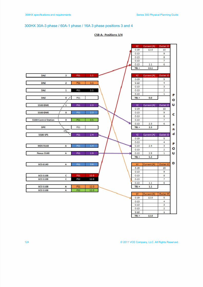
7/21/2019 VCE Vblock™ Systems 300 Physical Planning Guide (Cisco UCS)
http://slidepdf.com/reader/full/vce-vblock-systems-300-physical-planning-guide-cisco-ucs 124/132
124 © 2011 VCE Company, LLC. All Rights Reserved.
300HX specifications and requirements Series 300 Physical Planning Guide
300HX 30A-3 phase / 60A-1 phase / 16A 3 phase positions 3 and 4
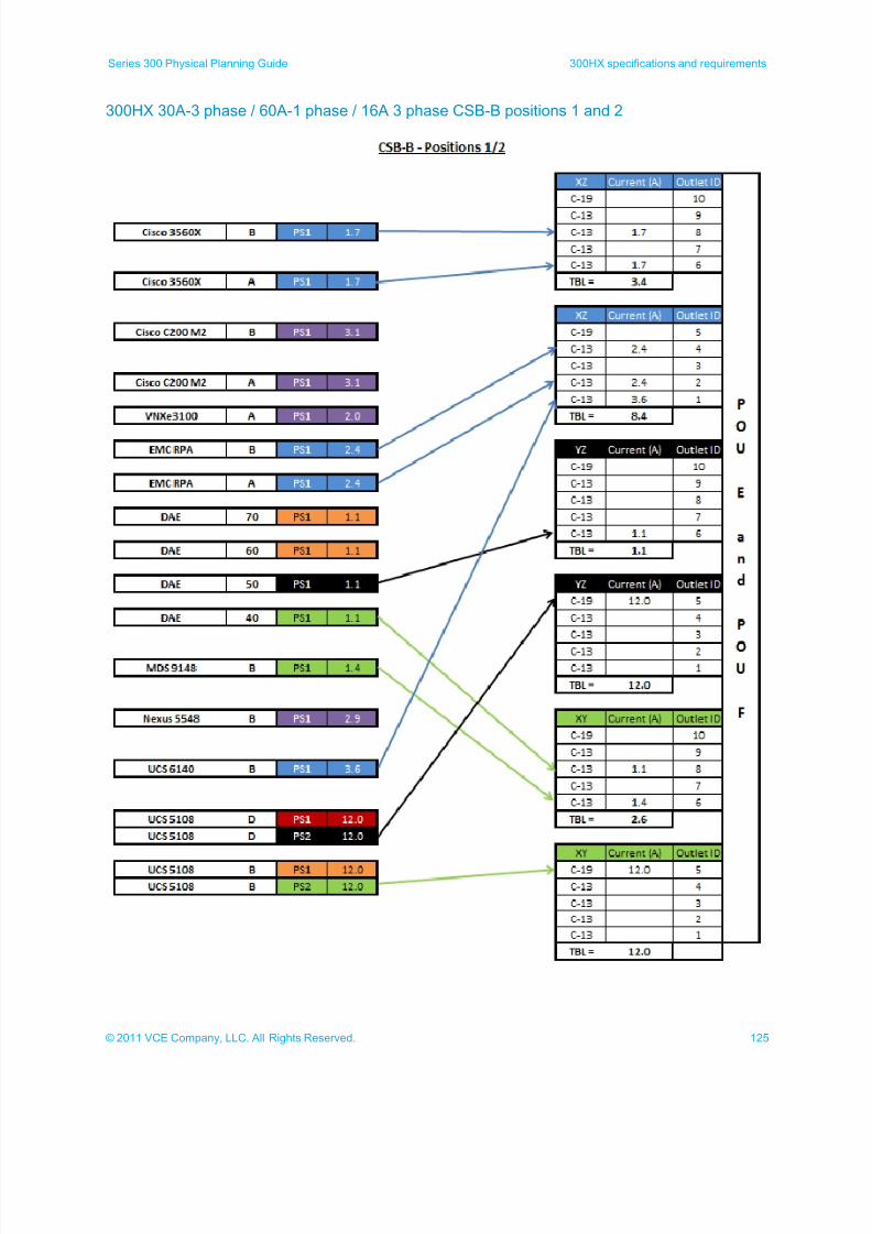
7/21/2019 VCE Vblock™ Systems 300 Physical Planning Guide (Cisco UCS)
http://slidepdf.com/reader/full/vce-vblock-systems-300-physical-planning-guide-cisco-ucs 125/132
125© 2011 VCE Company, LLC. All Rights Reserved.
Series 300 Physical Planning Guide 300HX specifications and requirements
300HX 30A-3 phase / 60A-1 phase / 16A 3 phase CSB-B positions 1 and 2
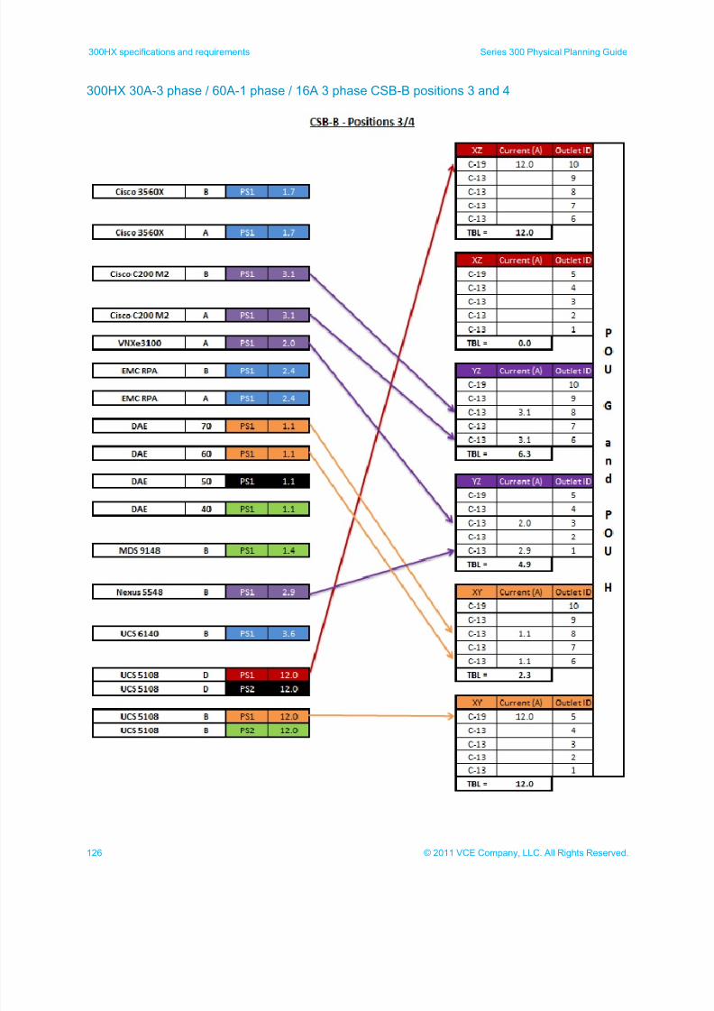
7/21/2019 VCE Vblock™ Systems 300 Physical Planning Guide (Cisco UCS)
http://slidepdf.com/reader/full/vce-vblock-systems-300-physical-planning-guide-cisco-ucs 126/132
126 © 2011 VCE Company, LLC. All Rights Reserved.
300HX specifications and requirements Series 300 Physical Planning Guide
300HX 30A-3 phase / 60A-1 phase / 16A 3 phase CSB-B positions 3 and 4
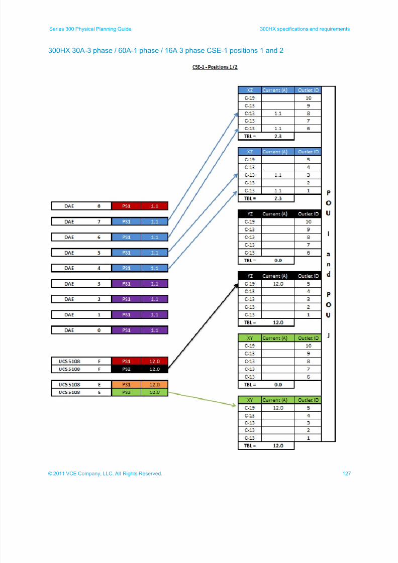
7/21/2019 VCE Vblock™ Systems 300 Physical Planning Guide (Cisco UCS)
http://slidepdf.com/reader/full/vce-vblock-systems-300-physical-planning-guide-cisco-ucs 127/132
127© 2011 VCE Company, LLC. All Rights Reserved.
Series 300 Physical Planning Guide 300HX specifications and requirements
300HX 30A-3 phase / 60A-1 phase / 16A 3 phase CSE-1 positions 1 and 2
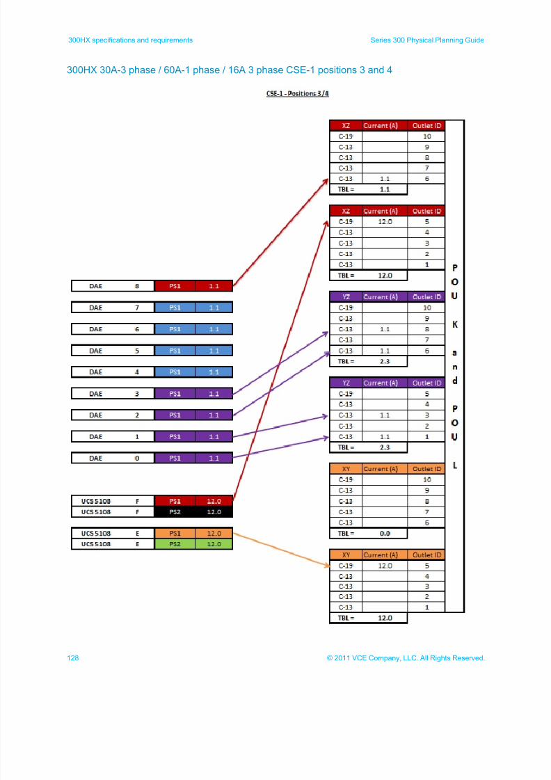
7/21/2019 VCE Vblock™ Systems 300 Physical Planning Guide (Cisco UCS)
http://slidepdf.com/reader/full/vce-vblock-systems-300-physical-planning-guide-cisco-ucs 128/132
128 © 2011 VCE Company, LLC. All Rights Reserved.
300HX specifications and requirements Series 300 Physical Planning Guide
300HX 30A-3 phase / 60A-1 phase / 16A 3 phase CSE-1 positions 3 and 4
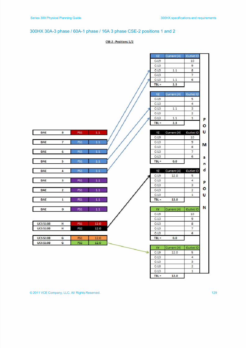
7/21/2019 VCE Vblock™ Systems 300 Physical Planning Guide (Cisco UCS)
http://slidepdf.com/reader/full/vce-vblock-systems-300-physical-planning-guide-cisco-ucs 129/132
129© 2011 VCE Company, LLC. All Rights Reserved.
Series 300 Physical Planning Guide 300HX specifications and requirements
300HX 30A-3 phase / 60A-1 phase / 16A 3 phase CSE-2 positions 1 and 2
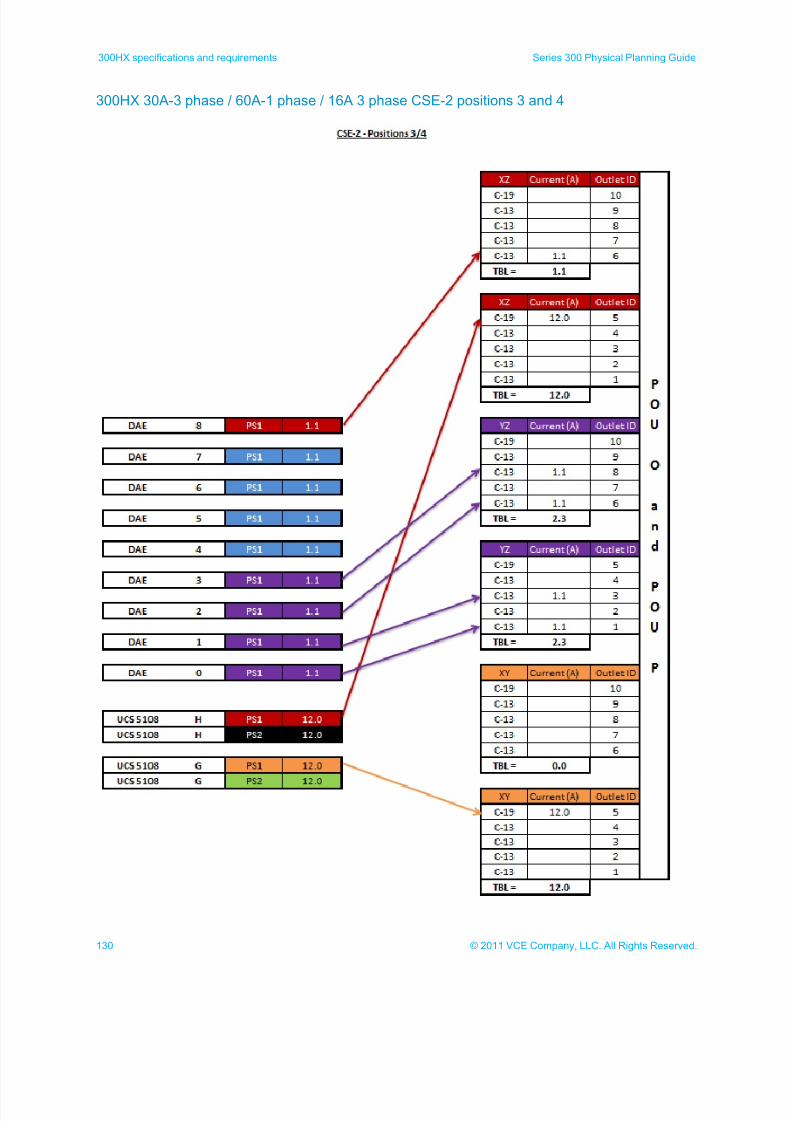
7/21/2019 VCE Vblock™ Systems 300 Physical Planning Guide (Cisco UCS)
http://slidepdf.com/reader/full/vce-vblock-systems-300-physical-planning-guide-cisco-ucs 130/132
130 © 2011 VCE Company, LLC. All Rights Reserved.
300HX specifications and requirements Series 300 Physical Planning Guide
300HX 30A-3 phase / 60A-1 phase / 16A 3 phase CSE-2 positions 3 and 4
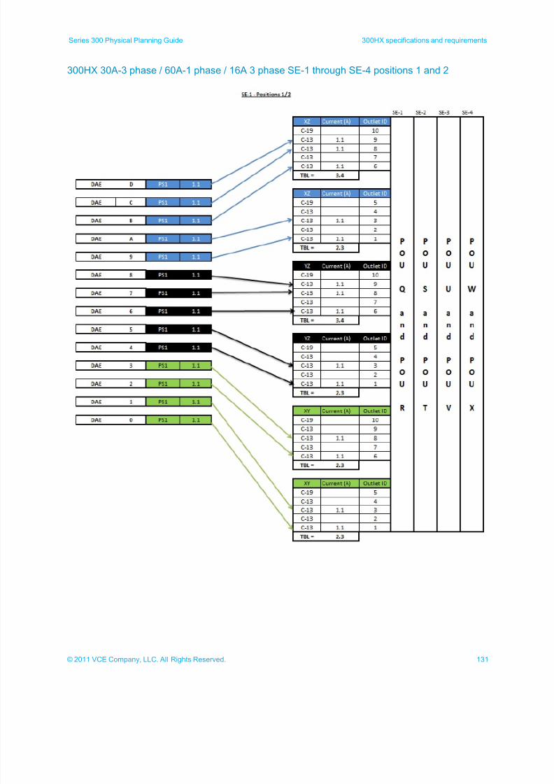
7/21/2019 VCE Vblock™ Systems 300 Physical Planning Guide (Cisco UCS)
http://slidepdf.com/reader/full/vce-vblock-systems-300-physical-planning-guide-cisco-ucs 131/132
131© 2011 VCE Company, LLC. All Rights Reserved.
Series 300 Physical Planning Guide 300HX specifications and requirements
300HX 30A-3 phase / 60A-1 phase / 16A 3 phase SE-1 through SE-4 positions 1 and 2
7/21/2019 VCE Vblock™ Systems 300 Physical Planning Guide (Cisco UCS)
http://slidepdf.com/reader/full/vce-vblock-systems-300-physical-planning-guide-cisco-ucs 132/132
300HX specifications and requirements Series 300 Physical Planning Guide
ABOUT VCE
VCE, the Virtual Computing Environment Company formed by Cisco and EMC with investments from VMware and Intel,
accelerates the adoption of converged infrastructure and cloud-based computing models that dramatically reduce the cost of ITwhile improving time to market for our customers. VCE, through the Vblock platform, delivers the industry's first completely
integrated IT offering with end-to-end vendor accountability. VCE's prepackaged solutions are available through an extensive
partner network, and cover horizontal applications, vertical industry offerings, and application development environments, allowing
customers to focus on business innovation instead of integrating, validating and managing IT infrastructure.
For more information, go to www.vce.com.