Embed Size (px)
Citation preview
DR
AF
T
vacuum technologies
VHS-10 & VHS-400 Diffusion Pumps
Part No. 699901023Rev. KDecember 2005
DR
AF
T
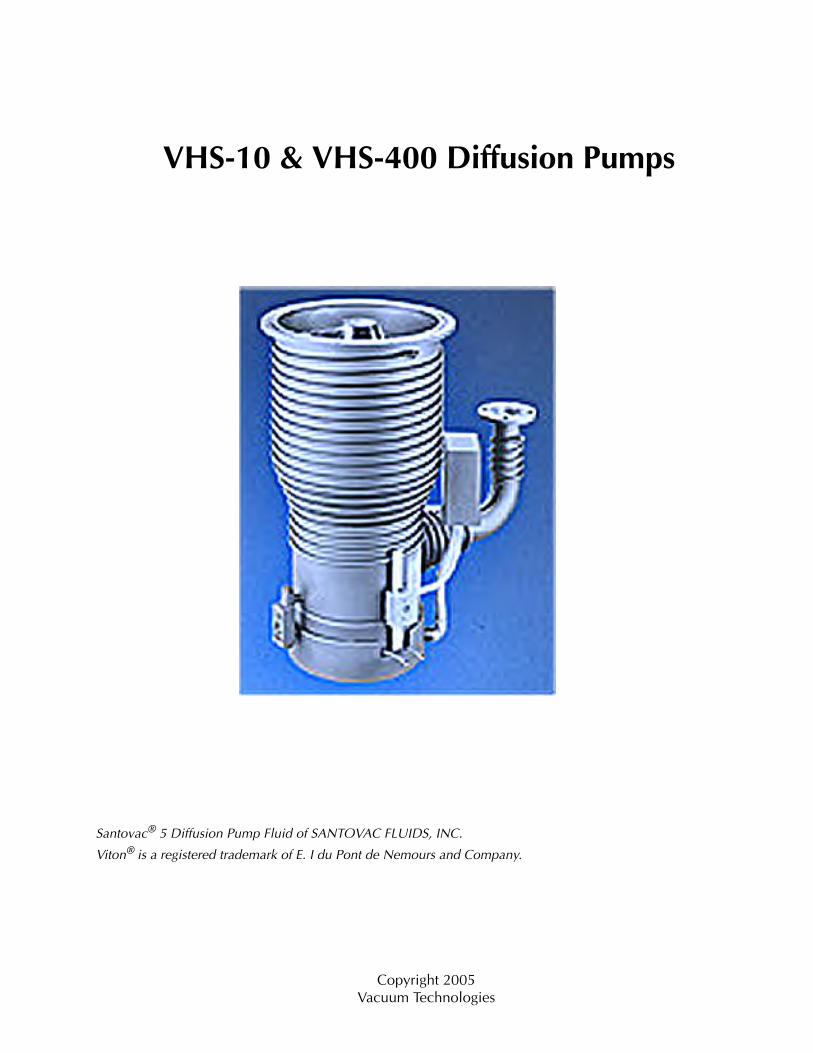
VHS-10 & VHS-400 Diffusion Pumps
Santovac® 5 Diffusion Pump Fluid of SANTOVAC FLUIDS, INC.
Viton® is a registered trademark of E. I du Pont de Nemours and Company.
Copyright 2005Vacuum Technologies
VHS-10 & VHS-400 Diffusion Pumps
DR
AF
T
Contents
Documentation Conventions ...................................................................................................... xiiDiffusion Pump Hazards ............................................................................................................. xii
Introduction ................................................................................................................................... 1-1Operating Characteristics............................................................................................................ 1-1Pump Air Speed and Throughput ................................................................................................ 1-5Physical Specifications................................................................................................................ 1-6Wiring Diagram .......................................................................................................................... 1-8
Installation ..................................................................................................................................... 2-1Unpacking .................................................................................................................................. 2-1Pump Oil Installation .................................................................................................................. 2-2Vacuum System Connections...................................................................................................... 2-2Cooling Water Connections ........................................................................................................ 2-3Electrical Connections ................................................................................................................ 2-4Thermal Switch Connections ...................................................................................................... 2-4
Operation ....................................................................................................................................... 3-1Startup Procedure ....................................................................................................................... 3-2Shutdown Procedure................................................................................................................... 3-2
Troubleshooting ............................................................................................................................ 4-1Leakage ...................................................................................................................................... 4-1Outgassing.................................................................................................................................. 4-1Poor Pump or System Performance ............................................................................................. 4-2
Appendix A. Maintenance ........................................................................................................... A-1Periodic Inspections ..............................................................................................................A-1Cleaning ...............................................................................................................................A-2Disassembly and Reassembly Procedures..............................................................................A-3
Appendix B. Parts ........................................................................................................................ B-1Replacement Parts ......................................................................................................................B-1
v
VHS-10 & VHS-400 Diffusion Pumps
DR
AF
T
List of Figures
1-1 VHS-10 Speed and Throughput Curves ................................................................................ 1-51-2 VHS-400 Speed and Throughput Curves .............................................................................. 1-51-3 VHS-10 and VHS-400 Outline with ASA Flanges ................................................................. 1-61-4 Operating Characteristics..................................................................................................... 1-8A-1 VHS-10 and VHS-400 Jet Assembly .....................................................................................A-4A-2 VHS-10 and VHS-400 Heater Connections ..........................................................................A-5A-3 Solid Steel and Slotted Stainless Clamp Plate .......................................................................A-6A-4 Fill and Drain Assemblies ....................................................................................................A-7
vii
VHS-10 & VHS-400 Diffusion Pumps
DR
AF
T
List of Tables
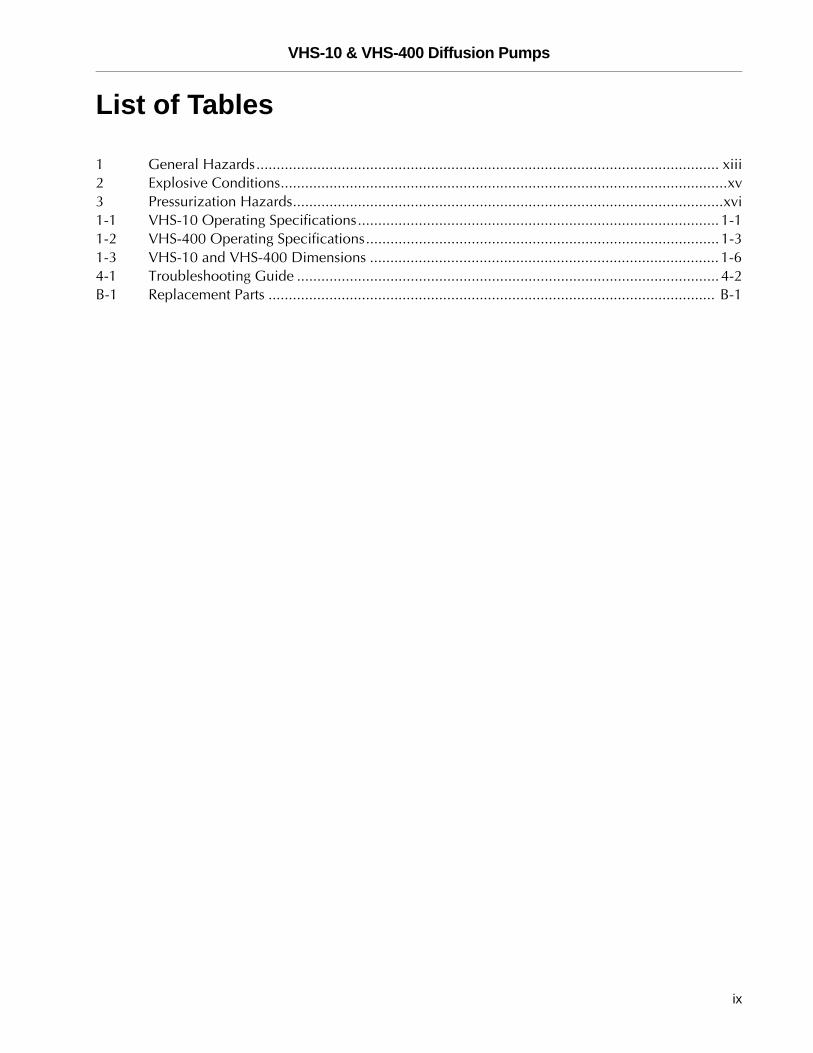
1 General Hazards.................................................................................................................. xiii2 Explosive Conditions..............................................................................................................xv3 Pressurization Hazards..........................................................................................................xvi1-1 VHS-10 Operating Specifications......................................................................................... 1-11-2 VHS-400 Operating Specifications....................................................................................... 1-31-3 VHS-10 and VHS-400 Dimensions ...................................................................................... 1-64-1 Troubleshooting Guide ........................................................................................................ 4-2B-1 Replacement Parts .............................................................................................................. B-1
ix
VHS-10 & VHS-400 Diffusion Pumps D
RA
FT
Preface
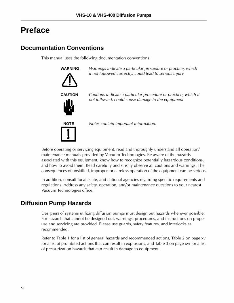
Documentation Conventions This manual uses the following documentation conventions:
WARNING Warnings indicate a particular procedure or practice, which if not followed correctly, could lead to serious injury.
CAUTION Cautions indicate a particular procedure or practice, which if not followed, could cause damage to the equipment.
NOTE Notes contain important information.
Before operating or servicing equipment, read and thoroughly understand all operation/maintenance manuals provided by Vacuum Technologies. Be aware of the hazards associated with this equipment, know how to recognize potentially hazardous conditions, and how to avoid them. Read carefully and strictly observe all cautions and warnings. The consequences of unskilled, improper, or careless operation of the equipment can be serious.
In addition, consult local, state, and national agencies regarding specific requirements and regulations. Address any safety, operation, and/or maintenance questions to your nearest Vacuum Technologies office.
Diffusion Pump HazardsDesigners of systems utilizing diffusion pumps must design out hazards wherever possible. For hazards that cannot be designed out, warnings, procedures, and instructions on proper use and servicing are provided. Please use guards, safety features, and interlocks as recommended.
Refer to Table 1 for a list of general hazards and recommended actions, Table 2 on page xv for a list of prohibited actions that can result in explosions, and Table 3 on page xvi for a list of pressurization hazards that can result in damage to equipment.
xii
VHS-10 & VHS-400 Diffusion Pumps
DR
AF
T
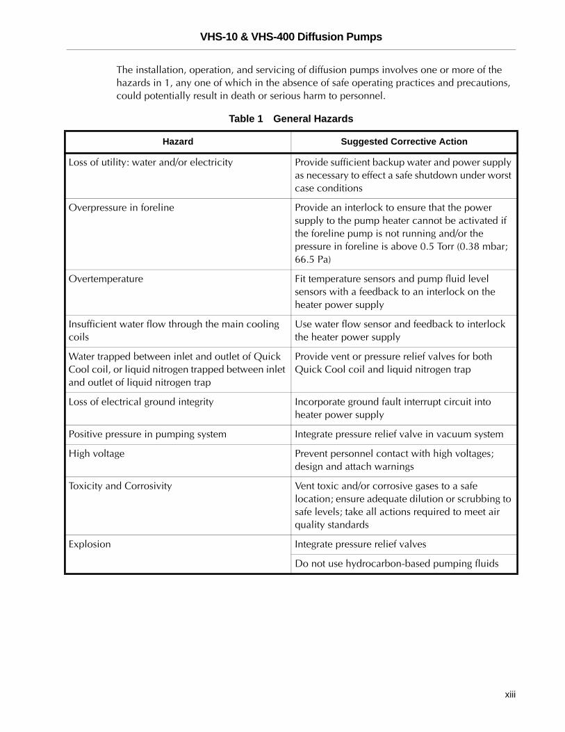
The installation, operation, and servicing of diffusion pumps involves one or more of the hazards in 1, any one of which in the absence of safe operating practices and precautions, could potentially result in death or serious harm to personnel.
Table 1 General Hazards
Hazard Suggested Corrective Action
Loss of utility: water and/or electricity Provide sufficient backup water and power supply as necessary to effect a safe shutdown under worst case conditions
Overpressure in foreline Provide an interlock to ensure that the power supply to the pump heater cannot be activated if the foreline pump is not running and/or the pressure in foreline is above 0.5 Torr (0.38 mbar; 66.5 Pa)
Overtemperature Fit temperature sensors and pump fluid level sensors with a feedback to an interlock on the heater power supply
Insufficient water flow through the main cooling coils
Use water flow sensor and feedback to interlock the heater power supply
Water trapped between inlet and outlet of Quick Cool coil, or liquid nitrogen trapped between inlet and outlet of liquid nitrogen trap
Provide vent or pressure relief valves for both Quick Cool coil and liquid nitrogen trap
Loss of electrical ground integrity Incorporate ground fault interrupt circuit into heater power supply
Positive pressure in pumping system Integrate pressure relief valve in vacuum system
High voltage Prevent personnel contact with high voltages; design and attach warnings
Toxicity and Corrosivity Vent toxic and/or corrosive gases to a safe location; ensure adequate dilution or scrubbing to safe levels; take all actions required to meet air quality standards
Explosion Integrate pressure relief valves
Do not use hydrocarbon-based pumping fluids
xiii
VHS-10 & VHS-400 Diffusion Pumps D
RA
FT
Explosion❑ Operation of the diffusion pump without continuous evacuation below 0.5 Torr
(0.67 mbar; 66.5 Pa), or without coolant and introducing a strong oxidizer (such as air) or explosive vapors or powders or materials which may react with pumping fluids in a hot pump (above 300 °F or 150 °C) can cause an explosion. Such an explosion can violently expel valves and other hardware, slam open doors that are not designed for appropriate pressure relief, or burst other components of the vacuum system. Serious injury or death may result from expelled parts, doors, shrapnel, and shock waves.
❑ Three elements are required for explosion: fuel, oxidizer, and an ignition. A combination of temperature and pressure can be a source of ignition. Most diffusion pump fluids are fuels. Hydrocarbon fluids are more prone to oxidize and explode than synthetic silicone-based fluid. The oxidizer can be air, which can be introduced by a leak, deliberately brought in via a process, or inadvertently admitted by operator error.Oxygen and other strong oxidizers are even more dangerous than air. Certain conditions of temperature and pressure can cause a combustible mixture to explode. The larger the diffusion pump, the greater the risk of explosion and the greater the risk of damage and injury. Never operate large diffusion pumps utilizing hydrocarbon oils without a complete safety analysis for the entire system and for the application.
❑ Explosion and Fire from Acetone and Alcohol: Diffusion pumps are typically cleaned with acetone and alcohol. When combined with air, oxygen, and other oxides, alcohol and most other solvents are very flammable and explosive. Never permit any trace of these cleaners to remain in or on the pump. Always remove all traces of alcohol and acetone and other cleaners with clean, dry, oil-free compressed air.
xiv
VHS-10 & VHS-400 Diffusion Pumps
DR
AF
T
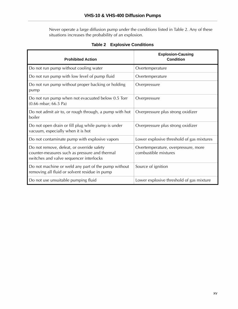
Never operate a large diffusion pump under the conditions listed in Table 2. Any of these situations increases the probability of an explosion.
Table 2 Explosive Conditions
Prohibited ActionExplosion-Causing
Condition
Do not run pump without cooling water Overtemperature
Do not run pump with low level of pump fluid Overtemperature
Do not run pump without proper backing or holding pump
Overpressure
Do not run pump when not evacuated below 0.5 Torr (0.66 mbar; 66.5 Pa)
Overpressure
Do not admit air to, or rough through, a pump with hot boiler
Overpressure plus strong oxidizer
Do not open drain or fill plug while pump is under vacuum, especially when it is hot
Overpressure plus strong oxidizer
Do not contaminate pump with explosive vapors Lower explosive threshold of gas mixtures
Do not remove, defeat, or override safety counter-measures such as pressure and thermal switches and valve sequencer interlocks
Overtemperature, overpressure, more combustible mixtures
Do not machine or weld any part of the pump without removing all fluid or solvent residue in pump
Source of ignition
Do not use unsuitable pumping fluid Lower explosive threshold of gas mixture
xv
VHS-10 & VHS-400 Diffusion Pumps D
RA
FT
Pressurization Hazards
Large vacuum pumps and their components are designed for vacuum service. They are not designed for pressurization, which could cause them to burst possibly expelling shrapnel at lethal velocities. Serious accidents have been caused by intentional pressurization of vacuum systems and their components.
❑ Never pressurize any part of a vacuum system for test or any other purpose.
❑ Always provide pressure relief when designing diffusion pumps into systems and ensure that pressure relief motion is limited to safe envelopes.
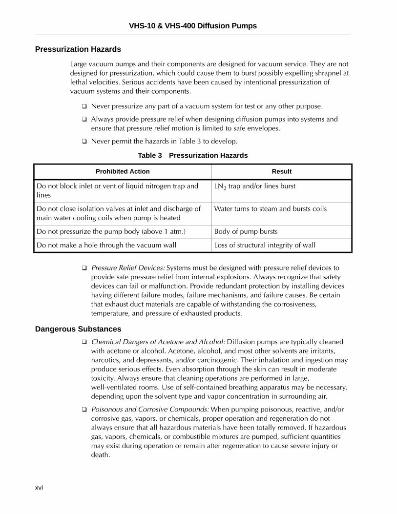
❑ Never permit the hazards in Table 3 to develop.
❑ Pressure Relief Devices: Systems must be designed with pressure relief devices to provide safe pressure relief from internal explosions. Always recognize that safety devices can fail or malfunction. Provide redundant protection by installing devices having different failure modes, failure mechanisms, and failure causes. Be certain that exhaust duct materials are capable of withstanding the corrosiveness, temperature, and pressure of exhausted products.
Dangerous Substances❑ Chemical Dangers of Acetone and Alcohol: Diffusion pumps are typically cleaned
with acetone or alcohol. Acetone, alcohol, and most other solvents are irritants, narcotics, and depressants, and/or carcinogenic. Their inhalation and ingestion may produce serious effects. Even absorption through the skin can result in moderate toxicity. Always ensure that cleaning operations are performed in large, well-ventilated rooms. Use of self-contained breathing apparatus may be necessary, depending upon the solvent type and vapor concentration in surrounding air.
❑ Poisonous and Corrosive Compounds: When pumping poisonous, reactive, and/or corrosive gas, vapors, or chemicals, proper operation and regeneration do not always ensure that all hazardous materials have been totally removed. If hazardous gas, vapors, chemicals, or combustible mixtures are pumped, sufficient quantities may exist during operation or remain after regeneration to cause severe injury or death.
Table 3 Pressurization Hazards
Prohibited Action Result
Do not block inlet or vent of liquid nitrogen trap and lines
LN2 trap and/or lines burst
Do not close isolation valves at inlet and discharge of main water cooling coils when pump is heated
Water turns to steam and bursts coils
Do not pressurize the pump body (above 1 atm.) Body of pump bursts
Do not make a hole through the vacuum wall Loss of structural integrity of wall
xvi
VHS-10 & VHS-400 Diffusion Pumps
DR
AF
T
❑ Pump Fluids: Overheating the pump fluid, exposing it to air or reactive materials, or over-pressurizing it above the normal operating range, approximately 1x10⁻³ Torr (1.3x10⁻³ mbar) decomposes the fluid and possibly makes it toxic. This is especially true of backstreamed mechanical pump fluids which are more volatile (unstable). Overheating of accidentally introduced or backstreamed mechanical pump fluids cannot be protected against by thermal switches which are set for diffusion pump fluid.
❑ Process Gasses: Process gasses are frequently toxic, flammable, corrosive, explosive, or otherwise reactive. Vacuum Technologies has no control over the types of gasses passing through the user’s diffusion pump as these are entirely under the control of the process user and/or the hardware systems integrator. Since these gasses can cause serious injury or death, it is very important to plumb the exhaust of the pump to the facility’s hazardous gas exhaust system which incorporates appropriate filters, scrubbers and similar components to ensure that the exhaust meets all air and water pollution control regulations.
High Temperatures❑ Hot Surfaces: Boiler temperatures reach 530 °F (275 °C) which can cause serious
burns. Always ensure that surfaces have cooled to near room temperature before touching them.
❑ Hot Cooling Water and Steam: The water used to cool the pump can reach scalding temperatures. Touching or rupture of the cooling surface can cause serious burns. Water left inside Quick Cool coils from previous use turns to steam when the pump is reheated. This steam must be allowed to escape without contacting personnel. Whenever possible, design the water system with interlock valves so that power cannot be applied to the pump unless water is flowing in the main cooling coils (not Quick Cool coils).
Cold Surfaces
Liquid nitrogen cooled traps are commonly used in diffusion pumps. Metal surfaces at liquid nitrogen temperature can cause severe frostbite. These surfaces remain cold in excess of 30 minutes after liquid nitrogen evaporation.
xvii
VHS-10 & VHS-400 Diffusion Pumps D
RA
FT
Cold Coolant
Liquid nitrogen. a cryogenic liquid, is used in traps. If it is splashed on body tissues or eyes, it can cause severe frostbite or blindness. The extremely low temperature of liquefied nitrogen can cause skin damage similar to high temperature burns. Contact with the cold gas evolving from the liquid can produce the same effect. Delicate tissues, such as the eye tissues, are most easily damaged by exposure to cold gas or liquid. To minimize the risk of hazardous contact of cold gaseous nitrogen with any part of the body, wear personal safety equipment recommended for use with cryogenic materials, including:
❑ Face shield
❑ Full-sleeved lab coat
❑ Clean, dry gloves which fit loosely so they can be thrown off quickly if frozen by contact with the gas.
High Voltages
Diffusion pump heaters operate at voltages (up to 480 V) high enough to kill. Design systems to prevent personnel contact with high voltages. Securely attach prominent hazard warnings. Personnel should always break the primary circuit to the power supply when direct access to the heater or wiring is required.
Large Equipment and Heavy Weights
The lifting and moving of large diffusion pumps requires power-assisted equipment and the use of trained moving and installation personnel to avoid dropping, slipping, and overturning the pump. Pumps weigh in excess of 180 lbs (81 kg) and are 3 to 6 feet in their largest dimension (1 to 2 meters). Their mishandling can cause severe injury. Check the weight of the equipment before lifting and assure that the power-assist device is adequate for the task. Do not stand under the equipment being lifted and moved.
Asphyxiation
Death from suffocation can result if a large amount of liquid nitrogen is spilled in a small, poorly ventilated room or equipment. All diffusion pumps are typically cleaned with acetone or alcohol. Acetone. alcohol, and most other solvents are very volatile (unstable). During cleaning. the volatility of these cleaners may permit their gases to displace air and its life-supporting oxygen which could cause death or serious injury by asphyxiation. Always ensure that cleaning operations are performed in large, well-ventilated areas.
xviii
VHS-10 & VHS-400 Diffusion Pumps
DR
AF
T
Introduction
This chapter consists of:
❑ “Operating Characteristics”
❑ “Pump Air Speed and Throughput” on page 1-5
❑ “Physical Specifications” on page 1-6
❑ “Wiring Diagram” on page 1-8
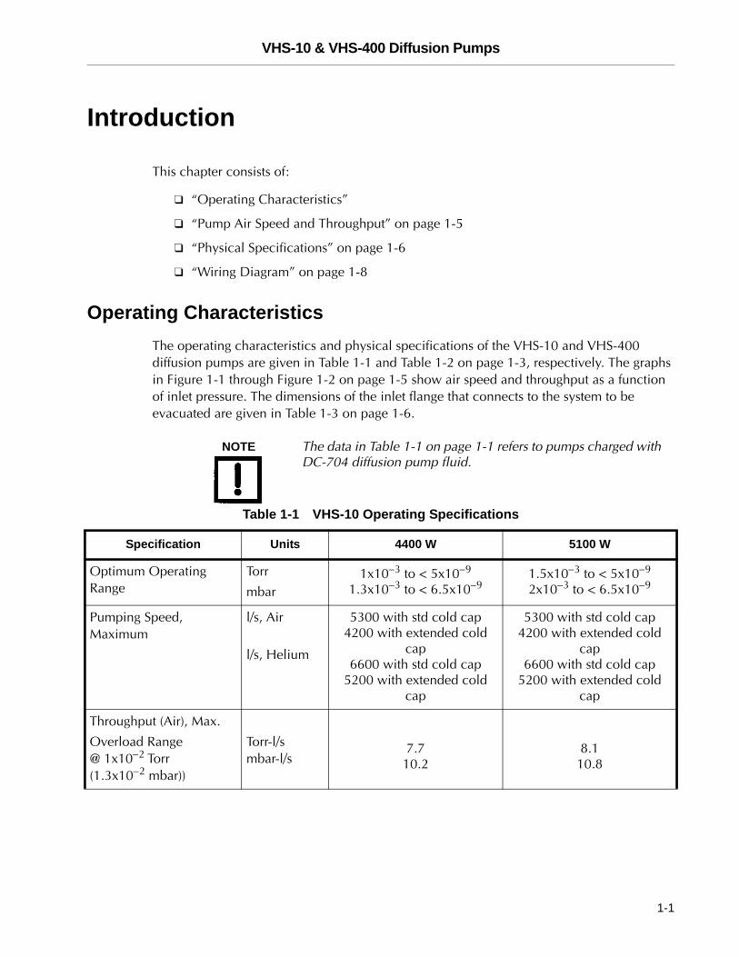
Operating CharacteristicsThe operating characteristics and physical specifications of the VHS-10 and VHS-400 diffusion pumps are given in Table 1-1 and Table 1-2 on page 1-3, respectively. The graphs in Figure 1-1 through Figure 1-2 on page 1-5 show air speed and throughput as a function of inlet pressure. The dimensions of the inlet flange that connects to the system to be evacuated are given in Table 1-3 on page 1-6.
NOTE The data in Table 1-1 on page 1-1 refers to pumps charged with DC-704 diffusion pump fluid.
Table 1-1 VHS-10 Operating Specifications
Specification Units 4400 W 5100 W
Optimum Operating Range
Torr
mbar1x10−3 to < 5x10⁻⁹
1.3x10⁻³ to < 6.5x10−91.5x10−3 to < 5x10⁻⁹
2x10⁻³ to < 6.5x10⁻⁹
Pumping Speed, Maximum
l/s, Air
l/s, Helium
5300 with std cold cap4200 with extended cold
cap6600 with std cold cap
5200 with extended cold cap
5300 with std cold cap4200 with extended cold
cap6600 with std cold cap
5200 with extended cold cap
Throughput (Air), Max.
Overload Range @ 1x10⁻² Torr (1.3x10⁻² mbar))
Torr-l/smbar-l/s
7.710.2
8.110.8
1-1
VHS-10 & VHS-400 Diffusion Pumps D
RA
FT
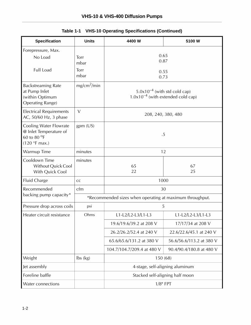
Forepressure, Max.
No Load
Full Load
Torrmbar
Torrmbar
0.650.87
0.550.73
Backstreaming Rate at Pump Inlet (within Optimum Operating Range)
mg/cm2/min5.0x10−4 (with std cold cap)
1.0x10⁻⁴ (with extended cold cap)
Electrical Requirements AC, 50/60 Hz, 3 phase
V208, 240, 380, 480
Cooling Water Flowrate @ Inlet Temperature of 60 to 80 oF (120 °F max.)
gpm (US)
.5
Warmup Time minutes 12
Cooldown TimeWithout Quick Cool With Quick Cool
minutes6522
6725
Fluid Charge cc 1000
Recommended backing pump capacity*
cfm 30
*Recommended sizes when operating at maximum throughput.
Pressure drop across coils psi 5
Heater circuit resistance Ohms L1-L2/L2-L3/L1-L3 L1-L2/L2-L3/L1-L3
19.6/19.6/39.2 at 208 V 17/17/34 at 208 V
26.2/26.2/52.4 at 240 V 22.6/22.6/45.1 at 240 V
65.6/65.6/131.2 at 380 V 56.6/56.6/113.2 at 380 V
104.7/104.7/209.4 at 480 V 90.4/90.4/180.8 at 480 V
Weight lbs (kg) 150 (68)
Jet assembly 4-stage, self-aligning aluminum
Foreline baffle Stacked self-aligning half moon
Water connections 1/8" FPT
Table 1-1 VHS-10 Operating Specifications (Continued)
Specification Units 4400 W 5100 W
1-2
VHS-10 & VHS-400 Diffusion Pumps
DR
AF
T
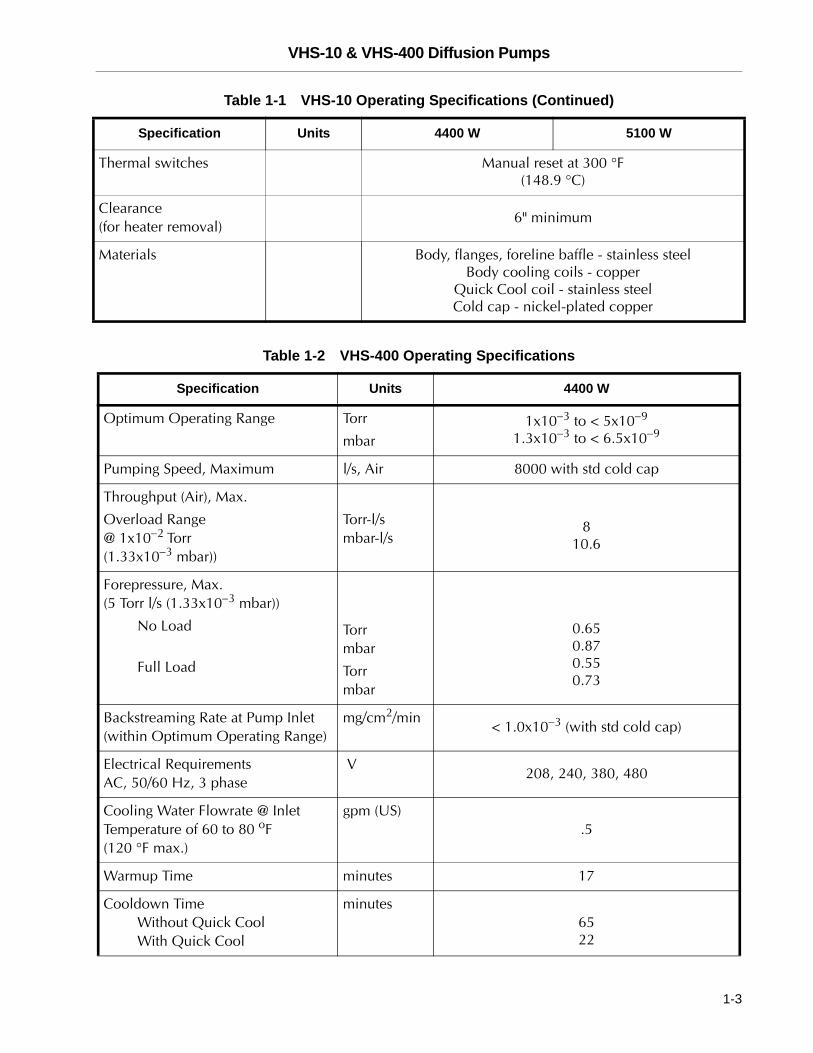
Thermal switches Manual reset at 300 °F (148.9 °C)
Clearance (for heater removal)
6" minimum
Materials Body, flanges, foreline baffle - stainless steelBody cooling coils - copper
Quick Cool coil - stainless steelCold cap - nickel-plated copper
Table 1-2 VHS-400 Operating Specifications
Specification Units 4400 W
Optimum Operating Range Torr
mbar1x10−3 to < 5x10⁻⁹
1.3x10⁻³ to < 6.5x10⁻⁹
Pumping Speed, Maximum l/s, Air 8000 with std cold cap
Throughput (Air), Max.
Overload Range @ 1x10⁻² Torr (1.33x10⁻³ mbar))
Torr-l/smbar-l/s
810.6
Forepressure, Max. (5 Torr l/s (1.33x10⁻³ mbar))
No Load
Full Load
Torrmbar
Torrmbar
0.650.870.550.73
Backstreaming Rate at Pump Inlet (within Optimum Operating Range)
mg/cm2/min< 1.0x10⁻³ (with std cold cap)
Electrical Requirements AC, 50/60 Hz, 3 phase
V208, 240, 380, 480
Cooling Water Flowrate @ Inlet Temperature of 60 to 80 oF (120 °F max.)
gpm (US).5
Warmup Time minutes 17
Cooldown TimeWithout Quick Cool With Quick Cool
minutes6522
Table 1-1 VHS-10 Operating Specifications (Continued)
Specification Units 4400 W 5100 W
1-3
VHS-10 & VHS-400 Diffusion Pumps D
RA
FT
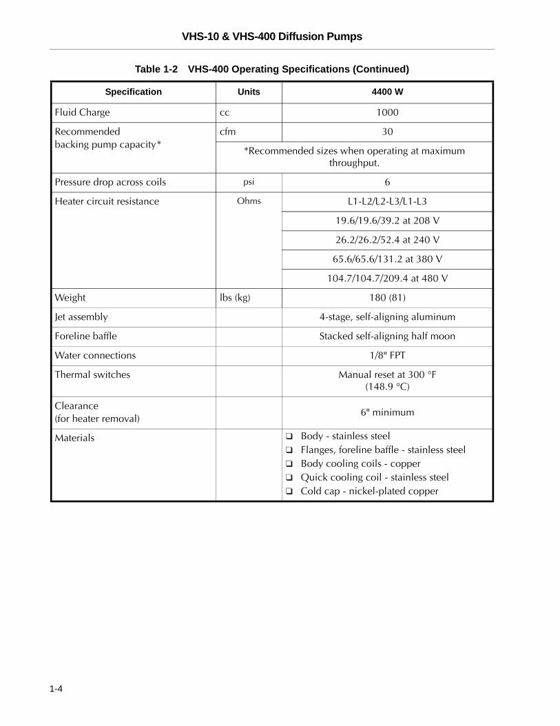
Fluid Charge cc 1000
Recommended backing pump capacity*
cfm 30
*Recommended sizes when operating at maximum throughput.
Pressure drop across coils psi 6
Heater circuit resistance Ohms L1-L2/L2-L3/L1-L3
19.6/19.6/39.2 at 208 V
26.2/26.2/52.4 at 240 V
65.6/65.6/131.2 at 380 V
104.7/104.7/209.4 at 480 V
Weight lbs (kg) 180 (81)
Jet assembly 4-stage, self-aligning aluminum
Foreline baffle Stacked self-aligning half moon
Water connections 1/8" FPT
Thermal switches Manual reset at 300 °F (148.9 °C)
Clearance (for heater removal)
6" minimum
Materials ❑ Body - stainless steel❑ Flanges, foreline baffle - stainless steel❑ Body cooling coils - copper❑ Quick cooling coil - stainless steel❑ Cold cap - nickel-plated copper
Table 1-2 VHS-400 Operating Specifications (Continued)
Specification Units 4400 W
1-4
VHS-10 & VHS-400 Diffusion Pumps
DR
AF
T
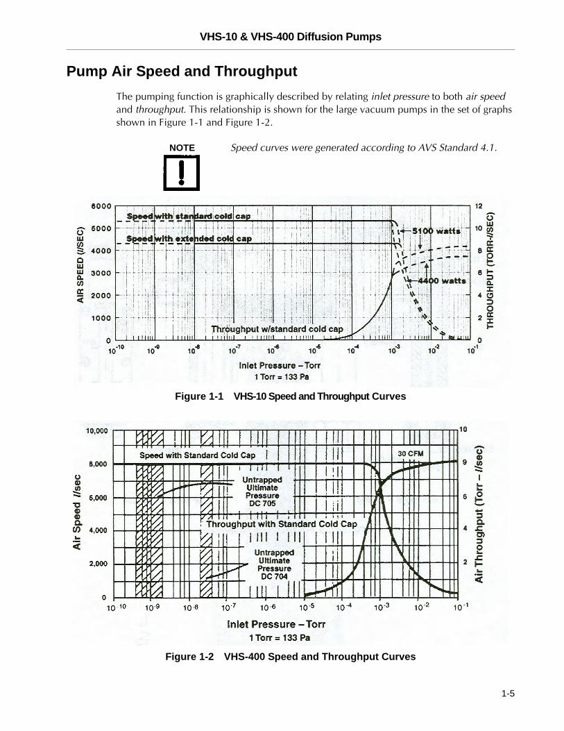
Pump Air Speed and ThroughputThe pumping function is graphically described by relating inlet pressure to both air speed and throughput. This relationship is shown for the large vacuum pumps in the set of graphs shown in Figure 1-1 and Figure 1-2.
NOTE Speed curves were generated according to AVS Standard 4.1.
Figure 1-1 VHS-10 Speed and Throughput Curves
Figure 1-2 VHS-400 Speed and Throughput Curves
1-5
VHS-10 & VHS-400 Diffusion Pumps D
RA
FT
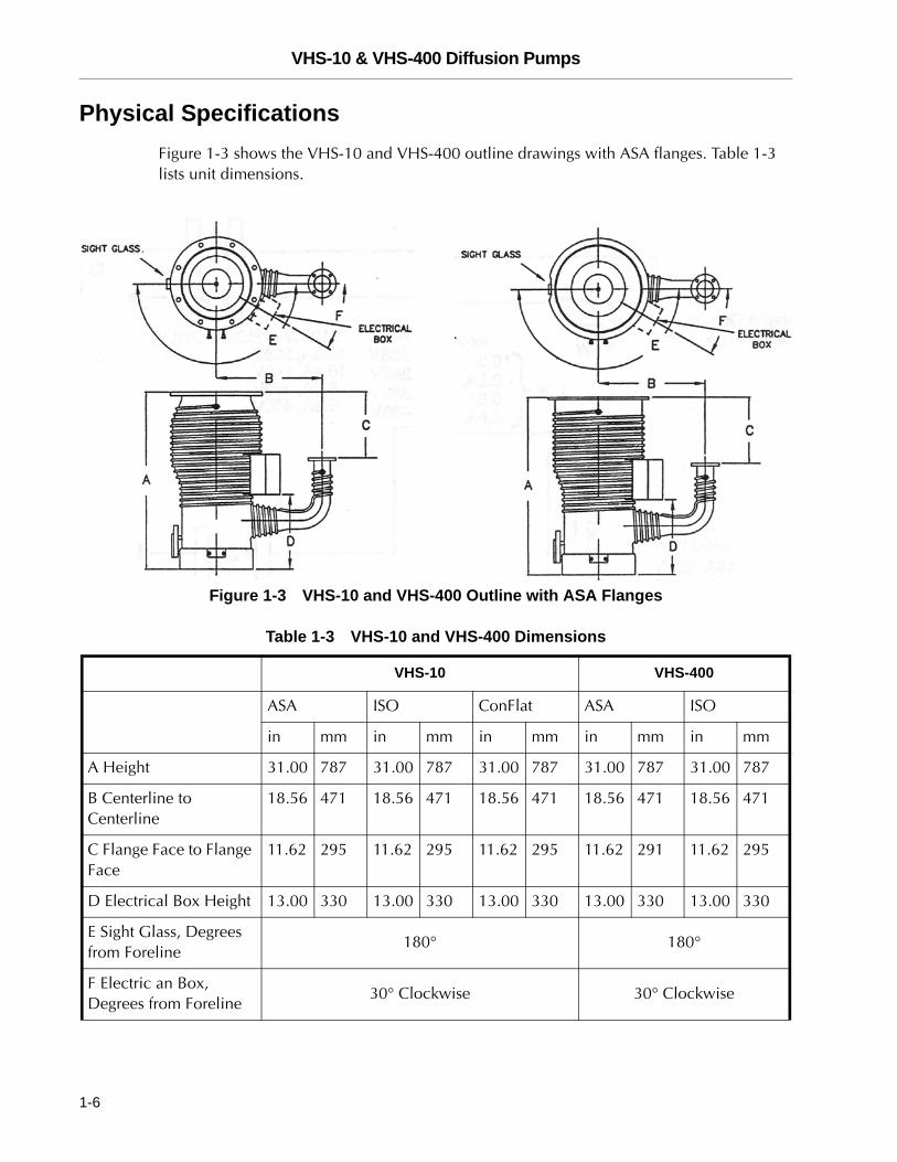
Physical SpecificationsFigure 1-3 shows the VHS-10 and VHS-400 outline drawings with ASA flanges. Table 1-3 lists unit dimensions.
Figure 1-3 VHS-10 and VHS-400 Outline with ASA Flanges
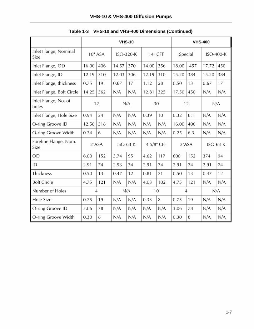
Table 1-3 VHS-10 and VHS-400 Dimensions
VHS-10 VHS-400
ASA ISO ConFlat ASA ISO
in mm in mm in mm in mm in mm
A Height 31.00 787 31.00 787 31.00 787 31.00 787 31.00 787
B Centerline to Centerline
18.56 471 18.56 471 18.56 471 18.56 471 18.56 471
C Flange Face to Flange Face
11.62 295 11.62 295 11.62 295 11.62 291 11.62 295
D Electrical Box Height 13.00 330 13.00 330 13.00 330 13.00 330 13.00 330
E Sight Glass, Degrees from Foreline
180° 180°
F Electric an Box, Degrees from Foreline
30° Clockwise 30° Clockwise
1-6
VHS-10 & VHS-400 Diffusion Pumps
DR
AF
T
VHS-10 VHS-400
Inlet Flange, Nominal Size
10" ASA ISO-320-K 14" CFF Special ISO-400-K
Inlet Flange, OD 16.00 406 14.57 370 14.00 356 18.00 457 17.72 450
Inlet Flange, ID 12.19 310 12.03 306 12.19 310 15.20 384 15.20 384
Inlet Flange, thickness 0.75 19 0.67 17 1.12 28 0.50 13 0.67 17
Inlet Flange, Bolt Circle 14.25 362 N/A N/A 12.81 325 17.50 450 N/A N/A
Inlet Flange, No. of holes
12 N/A 30 12 N/A
Inlet Flange, Hole Size 0.94 24 N/A N/A 0.39 10 0.32 8.1 N/A N/A
O-ring Groove ID 12.50 318 N/A N/A N/A N/A 16.00 406 N/A N/A
O-ring Groove Width 0.24 6 N/A N/A N/A N/A 0.25 6.3 N/A N/A
Foreline Flange, Nom. Size
2"ASA ISO-63-K 4 5/8" CFF 2"ASA ISO-63-K
OD 6.00 152 3.74 95 4.62 117 600 152 374 94
ID 2.91 74 2.93 74 2.91 74 2.91 74 2.91 74
Thickness 0.50 13 0.47 12 0.81 21 0.50 13 0.47 12
Bolt Circle 4.75 121 N/A N/A 4.03 102 4.75 121 N/A N/A
Number of Holes 4 N/A 10 4 N/A
Hole Size 0.75 19 N/A N/A 0.33 8 0.75 19 N/A N/A
O-ring Groove ID 3.06 78 N/A N/A N/A N/A 3.06 78 N/A N/A
O-ring Groove Width 0.30 8 N/A N/A N/A N/A 0.30 8 N/A N/A
Table 1-3 VHS-10 and VHS-400 Dimensions (Continued)
1-7
VHS-10 & VHS-400 Diffusion Pumps D
RA
FT
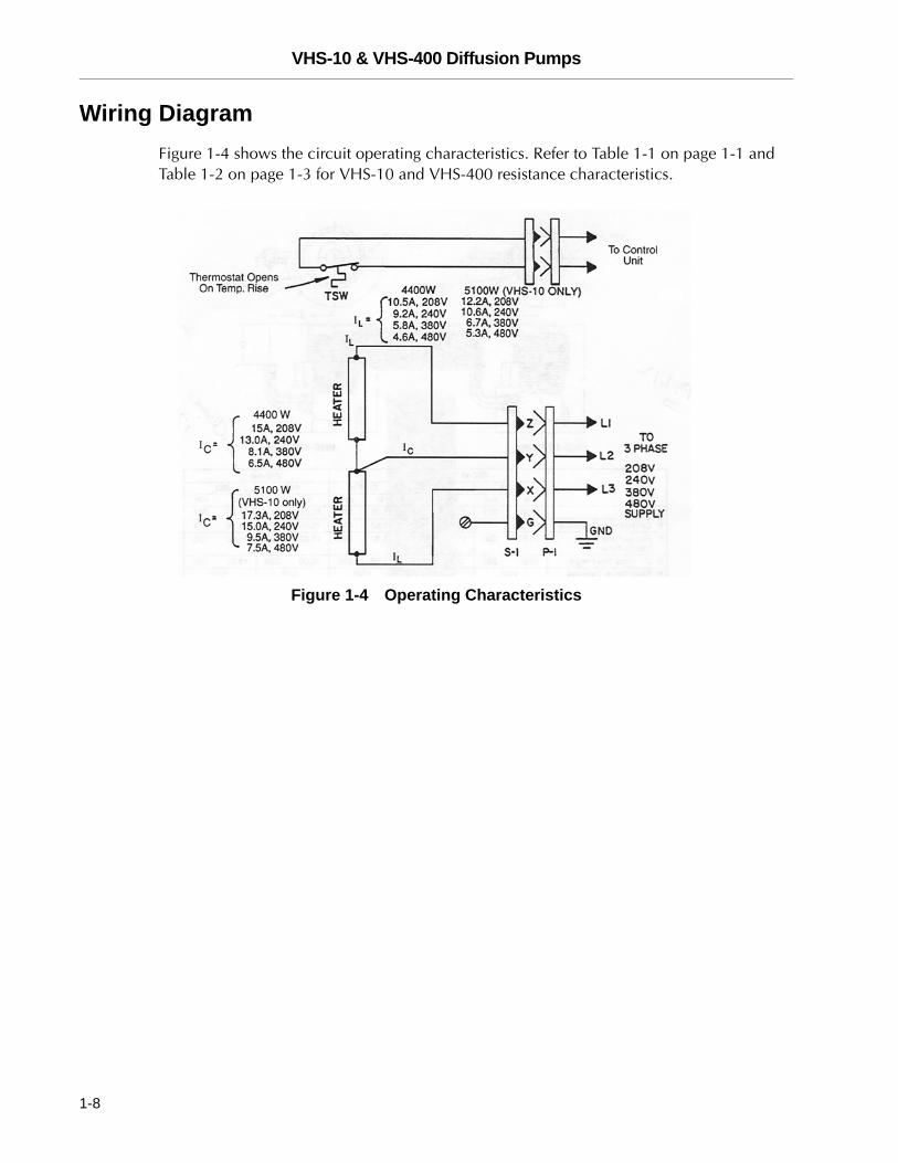
Wiring DiagramFigure 1-4 shows the circuit operating characteristics. Refer to Table 1-1 on page 1-1 and Table 1-2 on page 1-3 for VHS-10 and VHS-400 resistance characteristics.
Figure 1-4 Operating Characteristics
1-8
VHS-10 & VHS-400 Diffusion Pumps
DR
AF
T
Installation
Installation consists of:
❑ “Unpacking”
❑ “Pump Oil Installation” on page 2-2
❑ “Vacuum System Connections” on page 2-2
❑ “Cooling Water Connections” on page 2-3
❑ “Electrical Connections” on page 2-4
❑ “Thermal Switch Connections” on page 2-4
Unpacking
WARNING ❑ Before lifting a pump, check the weight of the equipment in Table 1-1 on page 1-1 or Table 1-2 on page 1-3.
❑ Use power-assisted equipment, and trained moving and installation personnel to avoid dropping, slipping, and overturning the pump and severely injuring personnel.
❑ Do not stand under equipment being moved.
Vacuum Technologies large diffusion pumps are shipped in sturdy containers that permit prolonged storage in suitably protected areas without special precautions, however, take care when moving the crated pump with a fork lift to avoid excessive shock.
Carefully remove the outer shipping container. Visually inspect the pump for damage that may have occurred during shipping and notify the carrier immediately if damage is suspected. If damage is noticed, save the crate and the internal packing for inspection.
To install the pump:
1. Remove flange covers and protective plugs from water connections. Be careful not to scratch the O-ring seal surface on the inlet and foreline flanges.
2. Inspect the internal jet assembly. It should be concentric and firmly seated on the bottom of the diffusion pump. Using a flashlight, ensure that the ejector nozzle is directly in line with the foreline. The location of the jet is controlled by an indexing pin located on the bottom of the pump.
If the required vacuum level is above 10-6 Torr, the pump requires no initial cleaning. For pressure below 10-6 Torr, follow the cleaning procedure in “Cleaning” on page A-2. Then charge the pump with the diffusion pump oil shipped with the pump.
2-1
VHS-10 & VHS-400 Diffusion Pumps D
RA
FT
Pump Oil InstallationThe recommended oil charge for the VHS-1 0 and the VHS-400 diffusion pumps is 1000 cc.
To fill the oil:
❑ Remove the fill plug and pour the oil into the pump inlet or the foreline by pouring it into the fill and drain assembly.
Vacuum System Connections
WARNING Utility failure can cause equipment damage, overheating and explosions. Use appropriate system design to protect personnel and property from possible hazards. Read all safety precautions.
To establish vacuum system connections:
1. Install the diffusion pump with the body vertical and plumb.
2. Ensure that the pump inlet mating flange on the system is horizontal within ± 1°.
The boiler plate must be horizontal to prevent uneven fluid level. Failure to meet this requirement could result in overheating of the diffusion pump boiler plate.
3. Prepare the inlet and foreline O-rings by wiping them with a clean, lint-free cloth. A small amount of diffusion pump oil can be used to clean the a-rings.
4. Install the O-rings in the O-ring grooves. Be careful not to damage or scratch the sealing surface.
5. Check the fill plug for tightness. Apply light to medium torque; enough to compress the O-rings.
6. Using the appropriate lifting apparatus, align the bolt holes of the inlet flange with the bolt holes of the mating flange.
7. Using the appropriate mounting hardware, tighten the bolts evenly until the O-ring is compressed and the flanges make light, metal-to-metal contact.
8. Ensure the integrity of the vacuum connections using a helium mass spectrometer leak detector before operating the vacuum system.
2-2
VHS-10 & VHS-400 Diffusion Pumps
DR
AF
T
Cooling Water ConnectionsTo install cooling water connections:
1. Connect the inlet water fitting (near the inlet flange at the top of the pump) to a continuously running water supply at 0.5 gpm and at a temperature of between 60 to 80 °F.
NOTE Install discharge connections in accordance with all applicable laws and regulations.
2. Ensure that the exit water temperature does not exceed 120°F.
3. Connect the outlet or discharge (nearest the foreline) to an open drain.
If the diffusion pump is being cooled by a recirculating water system:
❑ The system must be capable of adequate cooling and heat exchange to ensure a continuous inlet temperature of 60 to 80 °F.
❑ The recirculating system must also be capable of maintaining an adequate flow rate to ensure that exit water temperature does not exceed 120°F.
❑ The minimum rating of this system should be 85% of the maximum power rating of the diffusion pump.
If a Quick Cool coil is used:
1. Control the Quick Cool coil feed line, located at the boiler plate, using a separate three-way valve (open, closed, and vent to atmosphere).
2. Connect the Quick Cool drain to an open drain which is below the inlet connection of the Quick Cool coil. This ensures that the Quick Cool coil is completely drained when the cooling water supply is turned off and the pump is vented to atmosphere.
2-3
VHS-10 & VHS-400 Diffusion Pumps D
RA
FT
Electrical Connections
WARNING Diffusion pump heaters operate at fatal voltage levels. During installation, check all drawings and attach all hazard warnings and cautions. Read all safety precautions.
To complete electrical connections:
1. Verify the heater rating by measuring the resistance of the heater circuit (line-to-line) and comparing it to the values in Table 1-1 on page 1-1 for the VHS-10 or Table 1-2 on page 1-3 for the VHS-400.
2. Make the electrical connections in the junction box located near the foreline. The electrical supply should not be more than 5% above the rated voltage.
NOTE Make all electrical connections in accordance with all applicable laws and industrial codes.
Thermal Switch ConnectionsThe pump has been fitted with a factory preset manually-resettable thermal switch. This switch is located in a box near the bottom of the pump and provides protection to the pump in the event of excessive fluid loss, the loss of cooling water, or high inlet pressure.
WARNING Failure to properly connect the thermal circuit switch can result in catastrophic damage to personnel, the pump, or the vacuum system.
To connect the thermal switch:
❑ Connect the leads of the thermal switch in series with the coil of the heater power supply. In the event of overtemperature, the thermal switch opens and shuts off the power to the pump.
Reset the thermal switch by pressing the button located at the center of the thermal switch. This is done only after the root cause of a problem has been determined and the appropriate corrective action taken.
2-4
VHS-10 & VHS-400 Diffusion Pumps
DR
AF
T
Operation
Operation consists of:
❑ “Startup Procedure” on page 3-2
❑ “Shutdown Procedure” on page 3-2
During initial installation, the newly installed pump fluid may be subjected to degassing. This can result in foreline pressure fluctuations that are considered normal.
WARNING The following conditions increase the risk of explosion:
❑ Air leaks into the system
❑ Roughing through a hot diffusion pump, which can cause hot hydrocarbon fluids to ignite or explode when exposed to air
❑ Air release or the admission of air to a pump with a hot boiler (permitting a strong oxidizer to contact the hot pump fluid)
❑ Pressure above 1 milliTorr (1.3X10⁻³ mbar)
❑ Insufficient (or low level of) pump fluid
❑ Operating a pump without circulating cool water to the main body cooling coils
❑ Operating pump with water trapped in Quick Cool coil
❑ Foreign matter in the pumping fluid, which changes its viscosity and obstructs flow passages
CAUTION ❑ Do not turn on the heater without fluid in the pump. This may ruin the heaters and damage the pump.
❑ Do not air-release the pump while the boiler is hot. Most diffusion pump fluids break down under these conditions.
❑ Do not operate the pump heater unless cooling water is circulating. Doing so causes the pump and fluid to overheat.
❑ Do not operate without the internal splash baffle or a foreline baffle. This can cause a greater than normal fluid loss.
3-1
VHS-10 & VHS-400 Diffusion Pumps D
RA
FT
Startup ProcedureTo start the pump:
1. Visually inspect the sight glass assembly to ensure that the diffusion pump has been charged with the proper amount of diffusion pump fluid. When properly filled, the oil level (when the pump is cold) is even with the FULL/COLD mark on the oil level indicator.
2. Evacuate (rough pump) the diffusion pump with a mechanical backing pump (customer supplied). The pressure must be reduced to less than 0.5 Torr (0.66 mbar; 66.5 Pa). The backing pump should remain connected to the foreline of the diffusion pump.
3. Turn on the cooling water supply to the pump body. Check that the cooling water is not being supplied to the Quick Cool coil at this time.
4. Turn on the power to the diffusion pump heater.
5. Monitor inlet and foreline pressures.
During operation of the diffusion pump:
❑ The gas load at the inlet should not exceed the maximum throughput capability of the pump.
❑ The forepressure should not exceed the specified tolerable forepressure.
Shutdown Procedure
To shut down the pump:
1. Turn off the power to the diffusion pump. Continue to back the diffusion pump with the appropriate mechanical pump.
2. Allow cooling water to flow through the diffusion pump until the pump body temperature, located just above the boiler plate, has cooled to a temperature of 130 °F.
3. After isolating the backing pump, vent the diffusion pump to the atmosphere.
If faster cooling is desired:
Cool the pump using the Quick Cool coil at the bottom of the diffusion pump. The same procedure for shutdown can be followed.
3-2
VHS-10 & VHS-400 Diffusion Pumps
DR
AF
T
Troubleshooting
Troubleshooting consists of:
❑ “Leakage”
❑ “Outgassing”
❑ “Poor Pump or System Performance” on page 4-2
LeakageIf leakage is the suspected cause of poor system performance, first check the following items:
❑ Inlet and foreline connections
❑ Drain and fill plugs
❑ Other compression fittings, such as high-vacuum gauges in the system
❑ Threaded connections, such as a foreline gauge
Before proceeding with a program of step-by-step troubleshooting, check the performance and accuracy of the vacuum gauges used on the system.
OutgassingHigh-vacuum systems, even without external leakage, can have high gas loads due to outgassing from internal surfaces or processes. The pressure in the system is a result of gas load divided by pumping speed (p = Q/S). If the gas load Q exceeds the maximum throughput capability of the diffusion pump, the diffusion pump will not function and the pumping action will essentially be due to the mechanical backing pump.
To estimate the gas load, isolate the system from all pumps after evacuation and measure the rate of pressure increase.
The gas load can be estimated from the following relationship:
where V is the isolated volume, ∆P is the pressure rise, and ∆t is the time period of measurement.
Q V ∆P×∆t
------------------=
4-1
VHS-10 & VHS-400 Diffusion Pumps D
RA
FT
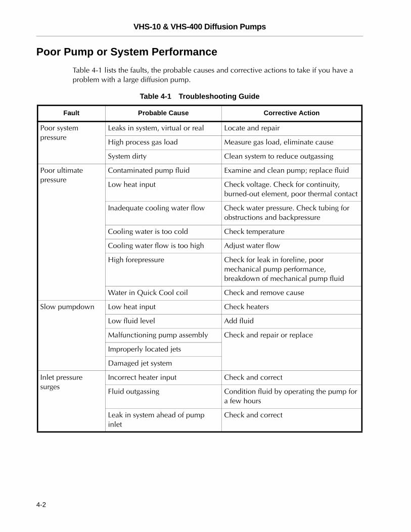
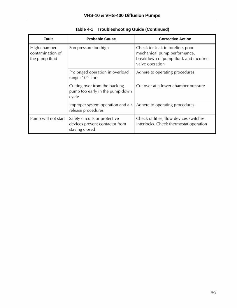
Poor Pump or System PerformanceTable 4-1 lists the faults, the probable causes and corrective actions to take if you have a problem with a large diffusion pump.
Table 4-1 Troubleshooting Guide
Fault Probable Cause Corrective Action
Poor system pressure
Leaks in system, virtual or real Locate and repair
High process gas load Measure gas load, eliminate cause
System dirty Clean system to reduce outgassing
Poor ultimate pressure
Contaminated pump fluid Examine and clean pump; replace fluid
Low heat input Check voltage. Check for continuity, burned-out element, poor thermal contact
Inadequate cooling water flow Check water pressure. Check tubing for obstructions and backpressure
Cooling water is too cold Check temperature
Cooling water flow is too high Adjust water flow
High forepressure Check for leak in foreline, poor mechanical pump performance, breakdown of mechanical pump fluid
Water in Quick Cool coil Check and remove cause
Slow pumpdown Low heat input Check heaters
Low fluid level Add fluid
Malfunctioning pump assembly Check and repair or replace
Improperly located jets
Damaged jet system
Inlet pressure surges
Incorrect heater input Check and correct
Fluid outgassing Condition fluid by operating the pump for a few hours
Leak in system ahead of pump inlet
Check and correct
4-2
VHS-10 & VHS-400 Diffusion Pumps
DR
AF
T
High chamber contamination of the pump fluid
Forepressure too high Check for leak in foreline, poor mechanical pump performance, breakdown of pump fluid, and incorrect valve operation
Prolonged operation in overload range: 10-3 Torr
Adhere to operating procedures
Cutting over from the backing pump too early in the pump down cycle
Cut over at a lower chamber pressure
Improper system operation and air release procedures
Adhere to operating procedures
Pump will not start Safety circuits or protective devices prevent contactor from staying closed
Check utilities, flow devices switches, interlocks. Check thermostat operation
Table 4-1 Troubleshooting Guide (Continued)
Fault Probable Cause Corrective Action
4-3
VHS-10 & VHS-400 Diffusion Pumps
DR
AF
T
Appendix A. Maintenance
Pump maintenance consists of:
❑ “Periodic Inspections”
❑ “Cleaning” on page A-2
❑ “Disassembly and Reassembly Procedures” on page A-3
❑ “Cold Cap” on page A-3
❑ “Jet Assembly” on page A-4
❑ “Heater Replacement” on page A-5
❑ “Pump Fluid” on page A-7
Perform these periodic checks to assure trouble-free operation. This maintenance prevents costly down-time and cleaning procedures. Maintain a day-to-day log of pump and system performance to identify marked variations that require corrective action.
Periodic Inspections
The maximum interval between inspection of the pump is established on the basis of experience.
WARNING ❑ High voltages (up to 480 V) can kill. Always break the primary circuit to the power supply before starting work on the heater or its wiring.
❑ Avoid the possibility of serious burns by making sure that the pump is at room temperature before attempting service.
❑ Always wear appropriate gloves and clothing and use a self-contained breathing apparatus. Poisonous or corrosive compounds may be present when opening the fill or drain.
❑ Explosion risk is high if the fill or drain is opened when the pump is running or when it is hot.
To perform general maintenance:
1. Check the condition and level of fluid when the pump is cold. Withdraw a sample through the drain and visually check the level of fluid through the sight glass. Slight discoloration of the fluid does not affect pump performance. Use new O-ring gaskets when replacing fill and drain plugs.
Loss of the fluid can be caused by:
❑ Admittance of excessive air or other gas to a hot pump
❑ Inadequate water cooling
A-1
VHS-10 & VHS-400 Diffusion Pumps D
RA
FT
❑ Continuous operation in the overload range as given in Table 1-1 on page 1-1 or Table 1-2 on page 1-3.
❑ Failure to reinsert the foreline baffle in the pump assembly
2. When the pump is cold, check that the heaters are bolted snugly to the boiler plate and that all heater terminal connections are fastened tightly inside the junction box.
3. Check the total heater power input and the balance of the load.
4. Ensure that cooling water flow is unobstructed and that the flow rate does not fall not below quantities specified in Table 1-1 on page 1-1 or Table 1-2 on page 1-3. In areas where the mineral content of the water is high or where there is considerable sediment, it may be advisable to install water filters.
Cleaning
WARNING ❑ Cleaning a diffusion pump involves the use of acetone and alcohol, both of which are toxic and explosive. Take careful note of the following warnings before starting a cleaning process.
❑ When heated, sprayed or exposed to high temperature equipment, these solvents become flammable and explosive, causing serious injury or death.
❑ When heated or sprayed, acetone or alcohol also becomes 4 to 5 times heavier than air and will flow down, settling in tanks, pits, and low areas, thus displacing air which can kill by asphyxiation.
❑ Acetone, alcohol, and other solvents are irritants, narcotics, depressants, and carcinogenic. Their inhalation and ingestion may produce serious effects. Prolonged or continued contact with the skin will result in absorption through the skin and moderate toxicity.
❑ Do not use near a high temperature source. Ventilate the working area with a blower and use in a large, well-ventilated room. The use of a self-contained breathing apparatus may also be necessary.
❑ Always ensure that cleaning operations are carried out in large, well-ventilated rooms. Wear eyeshields, gloves, and protective clothing.
Complete cleaning of the pump may be required due to gradual deterioration of pump fluids. Removal of the pump from the system is then necessary.
To clean an installed pump:
1. Turn off the power and disconnect the power supply plug.
2. Allow the pump to cool and turn off the cooling water and disconnect the cooling lines.
A-2
VHS-10 & VHS-400 Diffusion Pumps
DR
AF
T
3. Unbolt the inlet flange and foreline connections.
4. Remove the pump from the system. Drain the diffusion pump of all fluid.
5. Remove all O-rings, the cold cap assembly ( “Cold Cap” on page A-3), the jet assembly ( “Jet Assembly” on page A-4), and the foreline baffle from the pump.
6. Thoroughly clean the diffusion pump body interior and the jet assembly using acetone followed by an isopropyl alcohol rinse. Dry the pump and the jet assembly with clean, dry, oil-free compressed air.
7. Install the foreline baffle, the jet assembly, and the cold cap assembly in the pump body. Ensure that the:
❑ Ejector nozzle is properly aligned with the foreline.
❑ Cold cap is properly installed on the jet assembly. Ensure that the space between the underside of the cold cap and the outside of the jet cap is uniform.
8. Reinstall the diffusion pump in the system using all new O-rings.
9. Charge the pump with the proper amount of fluid (1000 cc).
10. Reconnect the water cooling lines and the power supply.
11. Evacuate the diffusion pump with the appropriate mechanical pump.
12. Turn on the cooling water.
13. Wait until the pump has been evacuated to a pressure below 0.5 Torr (0.38 mbar; 66.5 Pa) and turn on the power to the diffusion pump.
Disassembly and Reassembly Procedures
Cold Cap
To disassemble the cold cap:
1. Remove the screw that secures the cold cap to the jet assembly.
2. Loosen the bolt that secures the cold cap to the side of the pump.
3. Lift out the cold cap.
To reassemble the cold cap:
1. Place the cold cap on top of the jet assembly with the mounting bracket straddling the copper bar located on the inside wall of the pump and tighten it lightly.
2. Center and level the cold cap over the jet assembly, then install the screw that holds the cold cap to the jet assembly.
3. Tighten the bolt that secures the cold cap to the pump body.
A-3
VHS-10 & VHS-400 Diffusion Pumps D
RA
FT
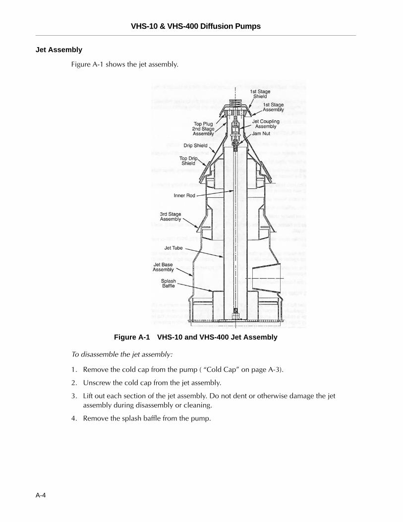
Jet Assembly
Figure A-1 shows the jet assembly.
Figure A-1 VHS-10 and VHS-400 Jet Assembly
To disassemble the jet assembly:
1. Remove the cold cap from the pump ( “Cold Cap” on page A-3).
2. Unscrew the cold cap from the jet assembly.
3. Lift out each section of the jet assembly. Do not dent or otherwise damage the jet assembly during disassembly or cleaning.
4. Remove the splash baffle from the pump.
A-4
VHS-10 & VHS-400 Diffusion Pumps
DR
AF
T
To assemble the jet assembly:
1. Place the splash baffle in the bottom of the pump. Check that it is located in the outer boiler groove.
2. Insert the jet base, making sure the ejector is aligned with the foreline, followed by the remaining stages of the jet. Make sure that all stages are firmly seated and that all drip shields are in place.
3. Install the cold cap assembly.
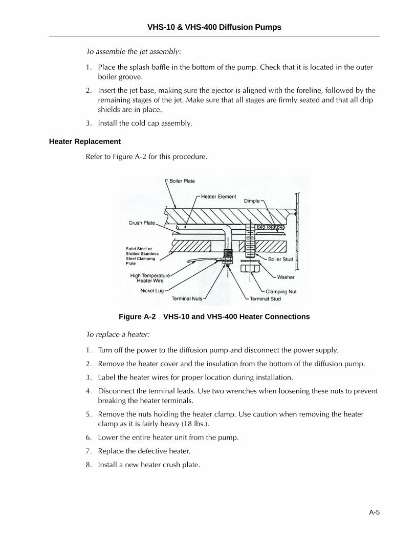
Heater Replacement
Refer to Figure A-2 for this procedure.
Figure A-2 VHS-10 and VHS-400 Heater Connections
To replace a heater:
1. Turn off the power to the diffusion pump and disconnect the power supply.
2. Remove the heater cover and the insulation from the bottom of the diffusion pump.
3. Label the heater wires for proper location during installation.
4. Disconnect the terminal leads. Use two wrenches when loosening these nuts to prevent breaking the heater terminals.
5. Remove the nuts holding the heater clamp. Use caution when removing the heater clamp as it is fairly heavy (18 lbs.).
6. Lower the entire heater unit from the pump.
7. Replace the defective heater.
8. Install a new heater crush plate.
A-5
VHS-10 & VHS-400 Diffusion Pumps D
RA
FT
9. Assemble the heater, crush plate (with dimples facing the heater element), and clamping plate as a unit.
10. Coat the boiler studs with an anti-seize compound such as Loctite C5-A or common milk of magnesia.
11. Support the heater unit by the clamping plate, line up the holes with the boiler studs, and push the unit up against the boiler plate. Use two nuts, tightened finger-tight, to hold it in place.
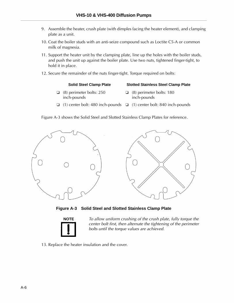
12. Secure the remainder of the nuts finger-tight. Torque required on bolts:
Figure A-3 shows the Solid Steel and Slotted Stainless Clamp Plates for reference.
Figure A-3 Solid Steel and Slotted Stainless Clamp Plate
NOTE To allow uniform crushing of the crush plate, fully torque the center bolt first, then alternate the tightening of the perimeter bolts until the torque values are achieved.
13. Replace the heater insulation and the cover.
Solid Steel Clamp Plate Slotted Stainless Steel Clamp Plate
❑ (8) perimeter bolts: 250 inch-pounds
❑ (8) perimeter bolts: 180 inch-pounds
❑ (1) center bolt: 480 inch-pounds ❑ (1) center bolt: 840 inch-pounds
A-6
VHS-10 & VHS-400 Diffusion Pumps
DR
AF
T
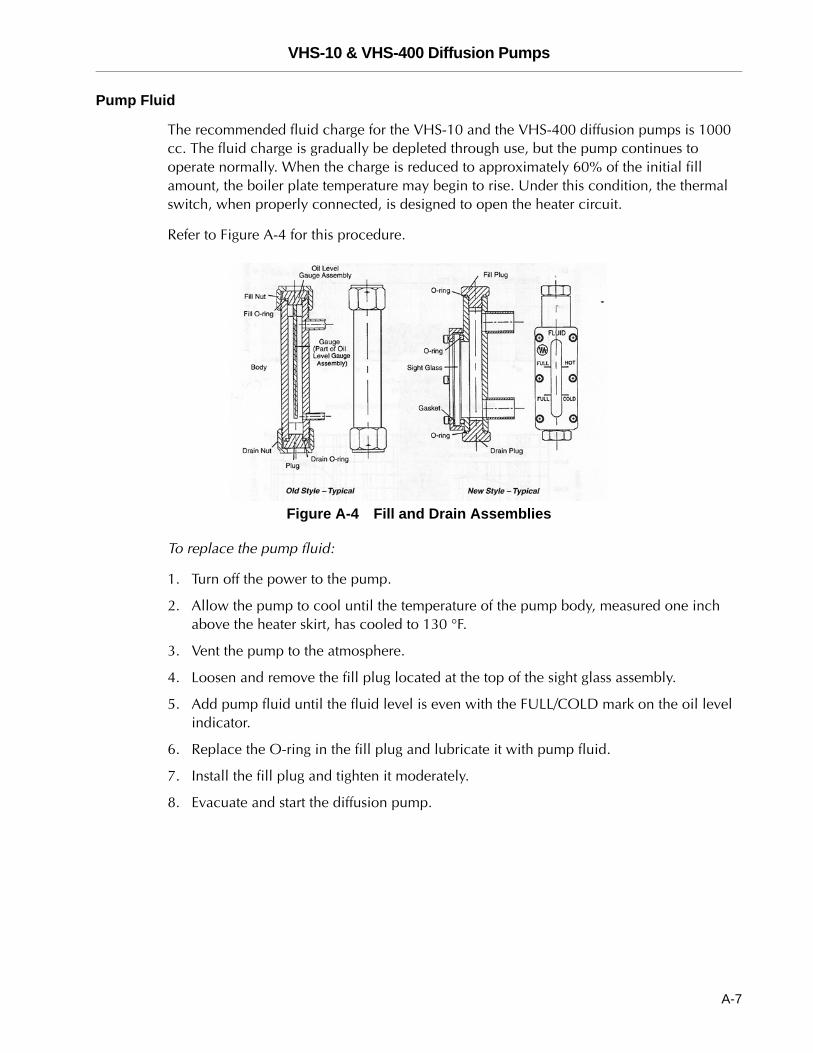
Pump Fluid
The recommended fluid charge for the VHS-10 and the VHS-400 diffusion pumps is 1000 cc. The fluid charge is gradually be depleted through use, but the pump continues to operate normally. When the charge is reduced to approximately 60% of the initial fill amount, the boiler plate temperature may begin to rise. Under this condition, the thermal switch, when properly connected, is designed to open the heater circuit.
Refer to Figure A-4 for this procedure.
Figure A-4 Fill and Drain Assemblies
To replace the pump fluid:
1. Turn off the power to the pump.
2. Allow the pump to cool until the temperature of the pump body, measured one inch above the heater skirt, has cooled to 130 °F.
3. Vent the pump to the atmosphere.
4. Loosen and remove the fill plug located at the top of the sight glass assembly.
5. Add pump fluid until the fluid level is even with the FULL/COLD mark on the oil level indicator.
6. Replace the O-ring in the fill plug and lubricate it with pump fluid.
7. Install the fill plug and tighten it moderately.
8. Evacuate and start the diffusion pump.
A-7
VHS-10 & VHS-400 Diffusion Pumps
DR
AF
T
Appendix B. Parts
Replacement Parts
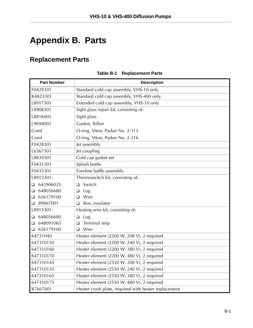
Table B-1 Replacement Parts
Part Number Description
F0429301 Standard cold cap assembly, VHS-10 onlyK4823301 Standard cold cap assembly, VHS-400 onlyL8917301 Extended cold cap assembly, VHS-10 onlyL8908301
L8816001
L9694001
Coml
Coml
Sight glass repair kit, consisting of:
Sight glass
Gasket, Teflon
O-ring, Viton, Parker No. 2-113
O-ring, Viton, Parker No. 2-216F0428301 Jet assembly L6367301 Jet couplingL8839301 Cold cap gasket setF0431301 Splash bottleF0435301 Foreline baffle assemblyL8912301:
❑ 642906025❑ 648056680❑ 656179100❑ 89867001
Thermoswitch kit, consisting of:
❑ Switch❑ Lug❑ Wire❑ Box, insulator
L8913301:
❑ 648056680❑ 648091065❑ 656179100
Heating wire kit, consisting of:
❑ Lug❑ Terminal strip❑ Wire
64731040 Heater element (2200 W, 208 V), 2 required647310150 Heater element (2200 W, 240 V), 2 required647310160 Heater element (2200 W, 380 V), 2 required647310170 Heater element (2200 W, 480 V), 2 required647310145 Heater element (2550 W, 208 V), 2 required647310155 Heater element (2550 W, 240 V), 2 required647310165 Heater element (2550 W, 380 V), 2 required647310175 Heater element (2550 W, 480 V), 2 requiredK7667001 Heater crush plate, required with heater replacement
B-1
VHS-10 & VHS-400 Diffusion Pumps D
RA
FT
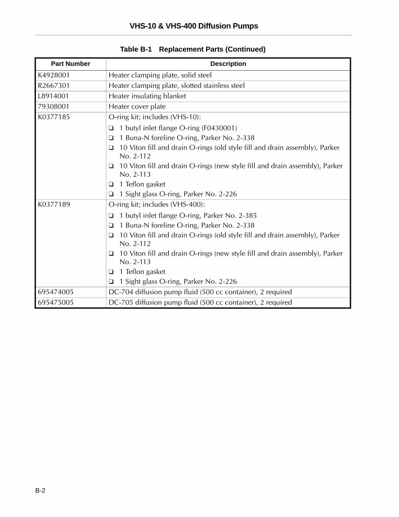
K4928001 Heater clamping plate, solid steelR2667301 Heater clamping plate, slotted stainless steelL8914001 Heater insulating blanket79308001 Heater cover plateK0377185 O-ring kit; includes (VHS-10):
❑ 1 butyl inlet flange O-ring (F0430001)❑ 1 Buna-N foreline O-ring, Parker No. 2-338❑ 10 Viton fill and drain O-rings (old style fill and drain assembly), Parker
No. 2-112❑ 10 Viton fill and drain O-rings (new style fill and drain assembly), Parker
No. 2-113❑ 1 Teflon gasket❑ 1 Sight glass O-ring, Parker No. 2-226
K0377189 O-ring kit; includes (VHS-400):
❑ 1 butyl inlet flange O-ring, Parker No. 2-385❑ 1 Buna-N foreline O-ring, Parker No. 2-338❑ 10 Viton fill and drain O-rings (old style fill and drain assembly), Parker
No. 2-112❑ 10 Viton fill and drain O-rings (new style fill and drain assembly), Parker
No. 2-113❑ 1 Teflon gasket❑ 1 Sight glass O-ring, Parker No. 2-226
695474005 DC-704 diffusion pump fluid (500 cc container), 2 required695475005 DC-705 diffusion pump fluid (500 cc container), 2 required
Table B-1 Replacement Parts (Continued)
Part Number Description
B-2