Embed Size (px)
Citation preview
robotics
Article
Workspace and Stiffness Analysis of 3D PrintingCable-Driven Parallel Robot with a RetractableBeam-Type End-Effector
Jinwoo Jung
School of Electronic and Electrical Engineering, Daegu Catholic University,Gyeongsan-si 38430, Gyeongsangbuk-do, Korea; [email protected]
Received: 14 July 2020; Accepted: 21 August 2020; Published: 24 August 2020�����������������
Abstract: 3D printing is a widely used technology that has been recently applied in construction toreduce construction time significantly. A large 3D printer often uses a traditional Cartesian robotwith inherent problems, such as position errors and printing nozzle vibrations, due to the long,heavy horizontal beam carrying it and a large amount of power required to actuate the heavy beam.A cable-driven parallel robot (CDPR) can be a good alternative system to reduce the vibrationsand necessary power because the robot’s lightweight cables can manipulate the printing nozzle.However, a large 3D printing CDPR should be carefully designed to maximize the workspace andavoid cable interference. It also needs to be stiff enough to reject disturbances from the environmentproperly. A CDPR with a retractable beam-type end-effector with cables through the guide pulleys ina single plane is suggested for avoiding cable interference while maximizing the workspace. Theeffects of using the retractable end-effector on the workspace were analyzed relative to the cableconnection points’ location changes. Static stiffness analysis was conducted to examine the naturalfrequencies, and the geometric parameters of the end-effector were adjusted to improve the lowestnatural frequencies. Simulation results show that a retractable beam-type end-effector can effectivelyexpand the wrench-feasible workspace.
Keywords: cable-driven parallel robot; retractable end-effector; workspace; stiffness; cable interference
1. Introduction
The application of 3D printing technology has been improved and expanded, including in theproduction of traditional plastics and metallic parts [1,2] to bio-printing objects [3]. Recently, theapplication of 3D printing technology has expanded further into large construction sites [4,5], as it cansignificantly reduce material consumption because materials may only be used where they are neededwhile reducing construction time by printing out complex structures without time-consuming assemblyprocesses. One popular system for implementing a 3D printer is a Cartesian robot that consists ofhorizontal and vertical beams. However, using a Cartesian robot introduces several problems. First,the horizontal beam carrying the printing nozzle tends to bend because of the nozzle’s weight. Second,when the 3D printer’s size increases, the horizontal beam becomes long and heavy, which inducesconsiderable bending and position errors when printing large structures.
Another promising system for 3D construction printing is a cable-driven parallel robot (CDPR)because it uses lightweight cables to manipulate an end-effector (Figure 1). A CDPR covers a large areabecause the robot provides a scalable workspace by changing the locations of its guide pulleys. Therehave been several studies on the use of CDPRs for large 3D construction printing [6–8]. However,developing a CDPR for 3D construction printing requires a careful design process because its designparameters can significantly affect workspace volume, cable interference with a printed structure,
Robotics 2020, 9, 65; doi:10.3390/robotics9030065 www.mdpi.com/journal/robotics
Robotics 2020, 9, 65 2 of 13
and robot stiffness. Most of the researchers for 3D construction printing have mainly focused on thedevelopment of a 3D-printing CDPR for construction, followed by the research of the investigationof the 3D-printing accuracy and the improvement based on the kinematic calibration. For most ofthe previously developed 3D-printing CDPRs for construction, suspended cable connection has beentypically selected for securing the workspace under the end-effector since there can be no cablespassing under the end-effector. A large suspended CDPR for construction, called Control of GiantRobots (CoGiRo), was developed and tested for the printing accuracy of a large wall [6]. A 3D printingCDPR was developed and the feasibility of its mechanism was investigated using simulation andexperiments [7]. The kinematic calibration method for a 3D-printing CDPR had been researched forimproving the accuracy of the robot [8]. The kinematics and statics of the 12-cable-driven robot withthe eight lower cables had been investigated [9]. A suspended CDPR combining CoGiRo [6] and the12-cable-driven robot [9] had been developed and its performance has been evaluated in terms ofenhancing the quality of the largely printed object [10]. However, a suspended CDPR has a significantdisadvantage that it does not have vertical stiffness since the end-effector is suspended vertically bythe gravitational force and not explicitly constrained by cables. Thus, if a suspended CDPR is exposedto vertical disturbances from the environment, such as vibration from a rock drill or sudden gust ofwind, its accuracy can be considerably degraded.
Robotics 2020, 9, x FOR PEER REVIEW 2 of 13
structure, and robot stiffness. Most of the researchers for 3D construction printing have mainly
focused on the development of a 3D-printing CDPR for construction, followed by the research of the
investigation of the 3D-printing accuracy and the improvement based on the kinematic calibration.
For most of the previously developed 3D-printing CDPRs for construction, suspended cable
connection has been typically selected for securing the workspace under the end-effector since there
can be no cables passing under the end-effector. A large suspended CDPR for construction, called
Control of Giant Robots (CoGiRo), was developed and tested for the printing accuracy of a large wall
[6]. A 3D printing CDPR was developed and the feasibility of its mechanism was investigated using
simulation and experiments [7]. The kinematic calibration method for a 3D-printing CDPR had been
researched for improving the accuracy of the robot [8]. The kinematics and statics of the 12-cable-
driven robot with the eight lower cables had been investigated [9]. A suspended CDPR combining
CoGiRo [6] and the 12-cable-driven robot [9] had been developed and its performance has been
evaluated in terms of enhancing the quality of the largely printed object [10]. However, a suspended
CDPR has a significant disadvantage that it does not have vertical stiffness since the end-effector is
suspended vertically by the gravitational force and not explicitly constrained by cables. Thus, if a
suspended CDPR is exposed to vertical disturbances from the environment, such as vibration from a
rock drill or sudden gust of wind, its accuracy can be considerably degraded.
Figure 1. An eight-cable vertically crossed over-constrained cable-driven parallel robot (CDPR).
In order to have vertical stiffness, the cables that provide the end-effector with vertical forces
can be additionally connected to the end-effector. In general, there are two methods of connecting
cables for providing the vertical forces: one is to connect the cables to the bottom tip of the end-effector
and guide them through the guide pulleys at the bottom of the external frame and the other is to
connect the cables to the top of the end-effector and guide them through the guide pulleys at the
bottom of the external frame. The latter method is a vertically crossed cable connection as shown in
Figure 1. While the use of the former method can easily cause the cable interference with a printed
object due to the cables fixed to the bottom tip of the end-effector, the latter method can allow more
workspace than the former method. However, the latter method still has the cables going toward the
bottom of the external frame and eventually leads to the cable interference with a printed object. For
example, a 3D-printing CDPR using the vertically crossed cables can have the cable interference
problem as shown in Figure 2. Considering the 3D-printing CDPR printing a tall and wide object, the
locations of the guide pulleys near the bottom may become lower than the height of the object being
printed. Along with the height increase of the printed object, when the 3D-printing CDPR tries to
print a corner of the object, the cables coming from the guide pulleys near the bottom will interfere
with the opposite corner of the printed object as shown in Figure 2.
Figure 1. An eight-cable vertically crossed over-constrained cable-driven parallel robot (CDPR).
In order to have vertical stiffness, the cables that provide the end-effector with vertical forces canbe additionally connected to the end-effector. In general, there are two methods of connecting cablesfor providing the vertical forces: one is to connect the cables to the bottom tip of the end-effector andguide them through the guide pulleys at the bottom of the external frame and the other is to connectthe cables to the top of the end-effector and guide them through the guide pulleys at the bottom ofthe external frame. The latter method is a vertically crossed cable connection as shown in Figure 1.While the use of the former method can easily cause the cable interference with a printed object dueto the cables fixed to the bottom tip of the end-effector, the latter method can allow more workspacethan the former method. However, the latter method still has the cables going toward the bottom ofthe external frame and eventually leads to the cable interference with a printed object. For example,a 3D-printing CDPR using the vertically crossed cables can have the cable interference problem asshown in Figure 2. Considering the 3D-printing CDPR printing a tall and wide object, the locationsof the guide pulleys near the bottom may become lower than the height of the object being printed.Along with the height increase of the printed object, when the 3D-printing CDPR tries to print a cornerof the object, the cables coming from the guide pulleys near the bottom will interfere with the oppositecorner of the printed object as shown in Figure 2.
Robotics 2020, 9, 65 3 of 13Robotics 2020, 9, x FOR PEER REVIEW 3 of 13
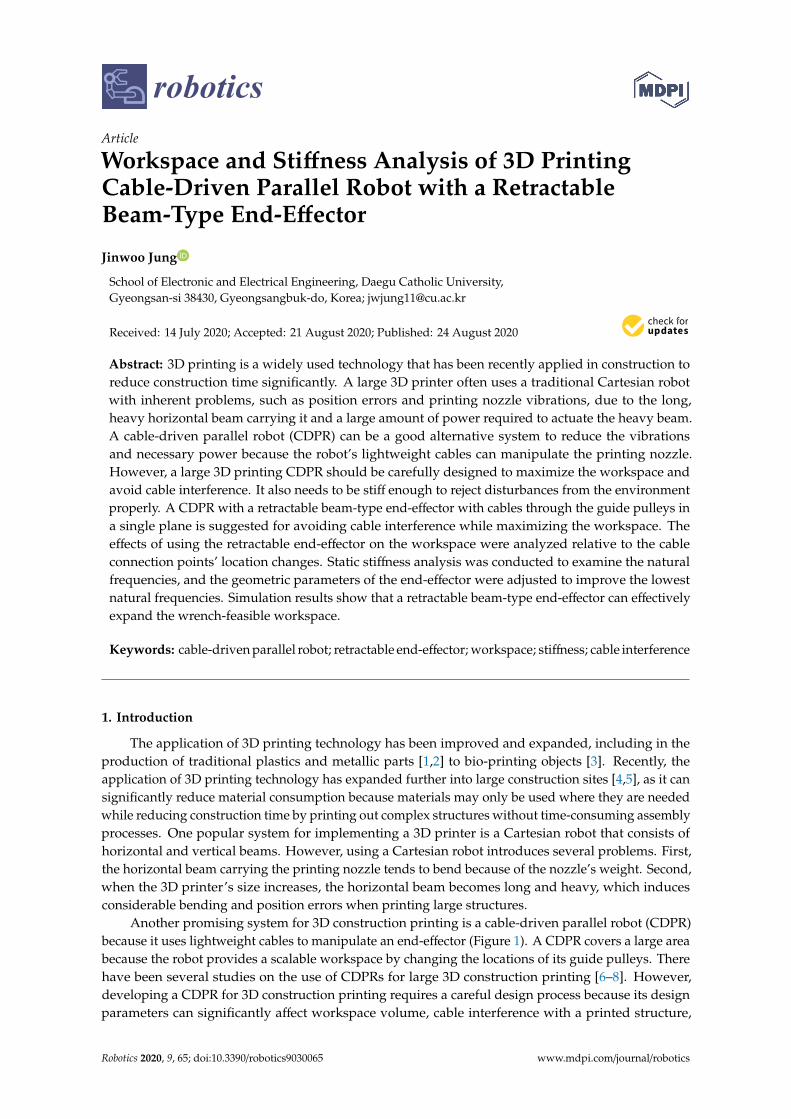
Figure 2. The cable interference with the printed object around a corner.
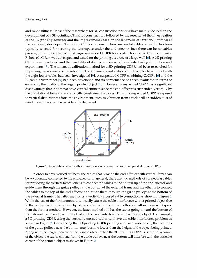
In order to solve the cable interference problem with the vertically crossed cables, the guide
pulleys near the bottom can be lifted up to the top plane as shown in Figure 3a. The height increase
of the guide pulleys can prevent the cables from occupying the workspace under the end-effector
while maintaining vertical stiffness. Along with the guide pulleys at the top plane, using the short
end-effector at the high positions can be advantageous to expand the horizontal workspace. This is
because the horizontal component of cable force increases with the use of the short end-effector as
shown in Figure 3b. In addition, the long end-effector is useful to reach low positions as shown in
Figure 3c.
(a) The end-effector with the
guide pulley in the top plane
(b) The short end-effector for
the high positions
(c) The long end-effector for
the low positions
Figure 3. The different lengths of the end-effector with the guide pulleys in the top plane.
Therefore, in this paper, for addressing the cable interference problem with maximizing the
workspace volume while providing vertical stiffness, a novel retractable beam type end-effector with
the guide pulleys distributed in a single horizontal plane is proposed for a 3D-printing CDPR as
shown in Figure 4. The cable interference with the objects printed in workspace can be avoided by
the cables guided thorough the guide pulleys in the horizontal top plane in Figure 4. This is because
there is no cable cutting across the workspace from the guide pulley at the bottom of the external
frame to the end-effector as compared to vertically crossed cable connection in Figure 1. To the best
of the author’s knowledge, there has been no attempt to use a retractable end-effector with the guide
pulleys in the same plane for 3D-printing application.
The use of the proposed end-effector should be investigated by conducting the workspace
analysis and stiffness analysis for CDPRs as the workspace analysis of CDPRs has been conducted
considering feasible tension distributions for various CDPRs [11–14]. In addition, the stiffness
analysis of CDPRs has been researched for several CDPRs [15–18].
Figure 2. The cable interference with the printed object around a corner.
In order to solve the cable interference problem with the vertically crossed cables, the guidepulleys near the bottom can be lifted up to the top plane as shown in Figure 3a. The height increaseof the guide pulleys can prevent the cables from occupying the workspace under the end-effectorwhile maintaining vertical stiffness. Along with the guide pulleys at the top plane, using the shortend-effector at the high positions can be advantageous to expand the horizontal workspace. This isbecause the horizontal component of cable force increases with the use of the short end-effector asshown in Figure 3b. In addition, the long end-effector is useful to reach low positions as shown inFigure 3c.
Robotics 2020, 9, x FOR PEER REVIEW 3 of 13
Figure 2. The cable interference with the printed object around a corner.
In order to solve the cable interference problem with the vertically crossed cables, the guide
pulleys near the bottom can be lifted up to the top plane as shown in Figure 3a. The height increase
of the guide pulleys can prevent the cables from occupying the workspace under the end-effector
while maintaining vertical stiffness. Along with the guide pulleys at the top plane, using the short
end-effector at the high positions can be advantageous to expand the horizontal workspace. This is
because the horizontal component of cable force increases with the use of the short end-effector as
shown in Figure 3b. In addition, the long end-effector is useful to reach low positions as shown in
Figure 3c.
(a) The end-effector with the
guide pulley in the top plane
(b) The short end-effector for
the high positions
(c) The long end-effector for
the low positions
Figure 3. The different lengths of the end-effector with the guide pulleys in the top plane.
Therefore, in this paper, for addressing the cable interference problem with maximizing the
workspace volume while providing vertical stiffness, a novel retractable beam type end-effector with
the guide pulleys distributed in a single horizontal plane is proposed for a 3D-printing CDPR as
shown in Figure 4. The cable interference with the objects printed in workspace can be avoided by
the cables guided thorough the guide pulleys in the horizontal top plane in Figure 4. This is because
there is no cable cutting across the workspace from the guide pulley at the bottom of the external
frame to the end-effector as compared to vertically crossed cable connection in Figure 1. To the best
of the author’s knowledge, there has been no attempt to use a retractable end-effector with the guide
pulleys in the same plane for 3D-printing application.
The use of the proposed end-effector should be investigated by conducting the workspace
analysis and stiffness analysis for CDPRs as the workspace analysis of CDPRs has been conducted
considering feasible tension distributions for various CDPRs [11–14]. In addition, the stiffness
analysis of CDPRs has been researched for several CDPRs [15–18].
Figure 3. The different lengths of the end-effector with the guide pulleys in the top plane.
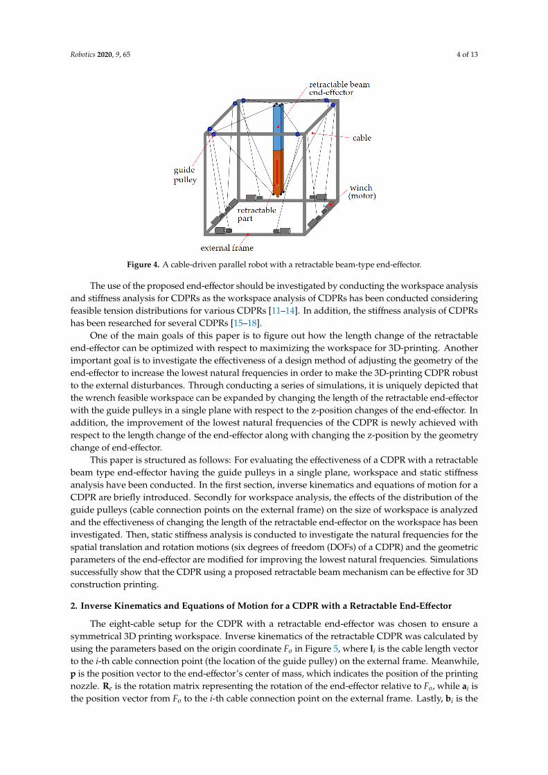
Therefore, in this paper, for addressing the cable interference problem with maximizing theworkspace volume while providing vertical stiffness, a novel retractable beam type end-effector withthe guide pulleys distributed in a single horizontal plane is proposed for a 3D-printing CDPR as shownin Figure 4. The cable interference with the objects printed in workspace can be avoided by the cablesguided thorough the guide pulleys in the horizontal top plane in Figure 4. This is because there is nocable cutting across the workspace from the guide pulley at the bottom of the external frame to theend-effector as compared to vertically crossed cable connection in Figure 1. To the best of the author’sknowledge, there has been no attempt to use a retractable end-effector with the guide pulleys in thesame plane for 3D-printing application.
Robotics 2020, 9, 65 4 of 13
Robotics 2020, 9, x FOR PEER REVIEW 4 of 13
One of the main goals of this paper is to figure out how the length change of the retractable end-
effector can be optimized with respect to maximizing the workspace for 3D-printing. Another
important goal is to investigate the effectiveness of a design method of adjusting the geometry of the
end-effector to increase the lowest natural frequencies in order to make the 3D-printing CDPR robust
to the external disturbances. Through conducting a series of simulations, it is uniquely depicted that
the wrench feasible workspace can be expanded by changing the length of the retractable end-effector
with the guide pulleys in a single plane with respect to the z-position changes of the end-effector. In
addition, the improvement of the lowest natural frequencies of the CDPR is newly achieved with
respect to the length change of the end-effector along with changing the z-position by the geometry
change of end-effector.
This paper is structured as follows: For evaluating the effectiveness of a CDPR with a retractable
beam type end-effector having the guide pulleys in a single plane, workspace and static stiffness
analysis have been conducted. In the first section, inverse kinematics and equations of motion for a
CDPR are briefly introduced. Secondly for workspace analysis, the effects of the distribution of the
guide pulleys (cable connection points on the external frame) on the size of workspace is analyzed
and the effectiveness of changing the length of the retractable end-effector on the workspace has been
investigated. Then, static stiffness analysis is conducted to investigate the natural frequencies for the
spatial translation and rotation motions (six degrees of freedom (DOFs) of a CDPR) and the geometric
parameters of the end-effector are modified for improving the lowest natural frequencies.
Simulations successfully show that the CDPR using a proposed retractable beam mechanism can be
effective for 3D construction printing.
Figure 4. A cable-driven parallel robot with a retractable beam-type end-effector.
2. Inverse Kinematics and Equations of Motion for a CDPR with a Retractable End-Effector
The eight-cable setup for the CDPR with a retractable end-effector was chosen to ensure a
symmetrical 3D printing workspace. Inverse kinematics of the retractable CDPR was calculated by
using the parameters based on the origin coordinate Fo in Figure 5, where li is the cable length vector
to the i-th cable connection point (the location of the guide pulley) on the external frame. Meanwhile,
p is the position vector to the end-effector’s center of mass, which indicates the position of the printing
nozzle. Re is the rotation matrix representing the rotation of the end-effector relative to Fo, while ai is
the position vector from Fo to the i-th cable connection point on the external frame. Lastly, bi is the
vector from the end-effector’s center of mass to the cable connection point on the end-effector. Thus,
the cable length vectors corresponding to the position of the end-effector can be calculated by using
the vector loop Equation (1).
Figure 4. A cable-driven parallel robot with a retractable beam-type end-effector.
The use of the proposed end-effector should be investigated by conducting the workspace analysisand stiffness analysis for CDPRs as the workspace analysis of CDPRs has been conducted consideringfeasible tension distributions for various CDPRs [11–14]. In addition, the stiffness analysis of CDPRshas been researched for several CDPRs [15–18].
One of the main goals of this paper is to figure out how the length change of the retractableend-effector can be optimized with respect to maximizing the workspace for 3D-printing. Anotherimportant goal is to investigate the effectiveness of a design method of adjusting the geometry of theend-effector to increase the lowest natural frequencies in order to make the 3D-printing CDPR robustto the external disturbances. Through conducting a series of simulations, it is uniquely depicted thatthe wrench feasible workspace can be expanded by changing the length of the retractable end-effectorwith the guide pulleys in a single plane with respect to the z-position changes of the end-effector. Inaddition, the improvement of the lowest natural frequencies of the CDPR is newly achieved withrespect to the length change of the end-effector along with changing the z-position by the geometrychange of end-effector.
This paper is structured as follows: For evaluating the effectiveness of a CDPR with a retractablebeam type end-effector having the guide pulleys in a single plane, workspace and static stiffnessanalysis have been conducted. In the first section, inverse kinematics and equations of motion for aCDPR are briefly introduced. Secondly for workspace analysis, the effects of the distribution of theguide pulleys (cable connection points on the external frame) on the size of workspace is analyzedand the effectiveness of changing the length of the retractable end-effector on the workspace has beeninvestigated. Then, static stiffness analysis is conducted to investigate the natural frequencies for thespatial translation and rotation motions (six degrees of freedom (DOFs) of a CDPR) and the geometricparameters of the end-effector are modified for improving the lowest natural frequencies. Simulationssuccessfully show that the CDPR using a proposed retractable beam mechanism can be effective for 3Dconstruction printing.
2. Inverse Kinematics and Equations of Motion for a CDPR with a Retractable End-Effector
The eight-cable setup for the CDPR with a retractable end-effector was chosen to ensure asymmetrical 3D printing workspace. Inverse kinematics of the retractable CDPR was calculated byusing the parameters based on the origin coordinate Fo in Figure 5, where li is the cable length vectorto the i-th cable connection point (the location of the guide pulley) on the external frame. Meanwhile,p is the position vector to the end-effector’s center of mass, which indicates the position of the printingnozzle. Re is the rotation matrix representing the rotation of the end-effector relative to Fo, while ai isthe position vector from Fo to the i-th cable connection point on the external frame. Lastly, bi is the
Robotics 2020, 9, 65 5 of 13
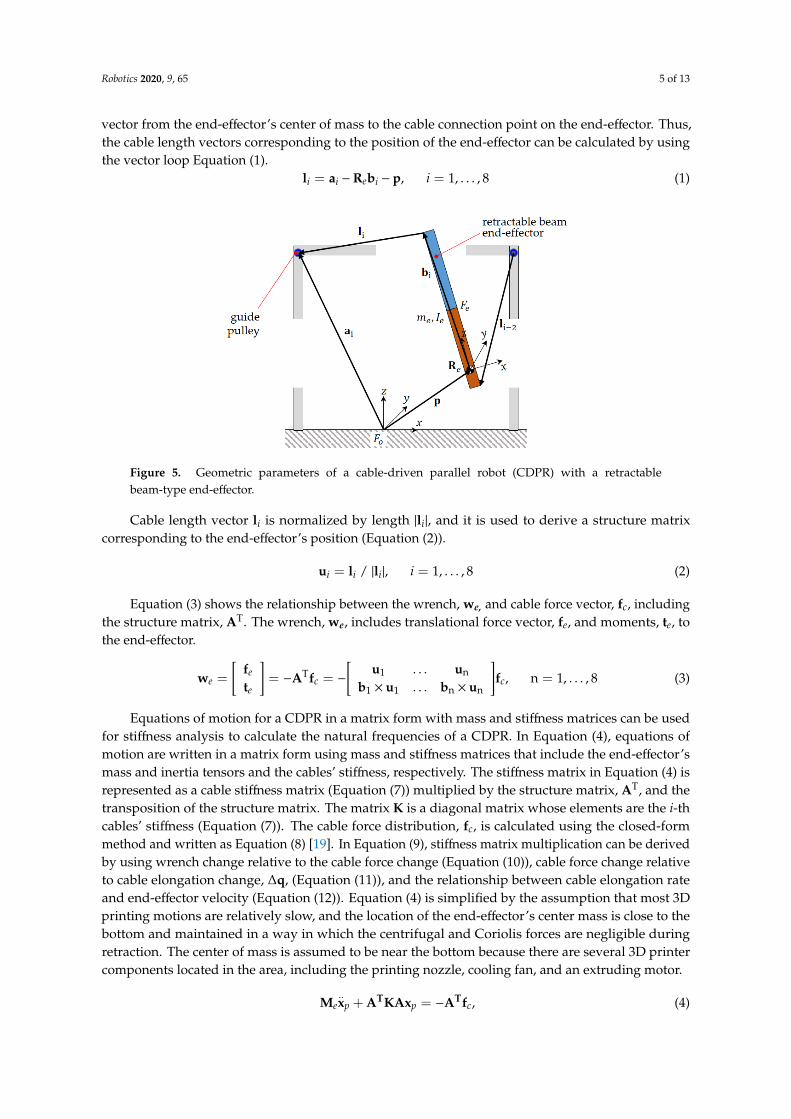
vector from the end-effector’s center of mass to the cable connection point on the end-effector. Thus,the cable length vectors corresponding to the position of the end-effector can be calculated by usingthe vector loop Equation (1).
li = ai −Rebi − p, i = 1, . . . , 8 (1)Robotics 2020, 9, x FOR PEER REVIEW 5 of 13
Figure 5. Geometric parameters of a cable-driven parallel robot (CDPR) with a retractable
beam-type end-effector.
𝐥𝒊 = 𝐚𝒊 − 𝐑𝒆𝐛𝒊 − 𝐩, 𝑖 = 1, . . . ,8 (1)
Cable length vector li is normalized by length |li|, and it is used to derive a structure matrix
corresponding to the end-effector’s position (Equation (2)).
𝐮𝑖 = 𝐥𝑖 / |𝐥𝑖|, 𝑖 = 1, . . . ,8 (2)
Equation (3) shows the relationship between the wrench, we, and cable force vector, fc, including
the structure matrix, AT. The wrench, we, includes translational force vector, fe, and moments, te, to
the end-effector.
𝐰𝑒 = [𝐟𝑒
𝐭𝑒] = −𝐀T𝐟𝑐 = − [
𝐮1 … 𝐮n
𝐛1 × 𝐮1 … 𝐛n × 𝐮n] 𝐟𝑐, n = 1, … ,8 (3)
Equations of motion for a CDPR in a matrix form with mass and stiffness matrices can be used
for stiffness analysis to calculate the natural frequencies of a CDPR. In Equation (4), equations of
motion are written in a matrix form using mass and stiffness matrices that include the end-effector’s
mass and inertia tensors and the cables’ stiffness, respectively. The stiffness matrix in Equation (4) is
represented as a cable stiffness matrix (Equation (7)) multiplied by the structure matrix, AT, and the
transposition of the structure matrix. The matrix K is a diagonal matrix whose elements are the i-th
cables’ stiffness (Equation (7)). The cable force distribution, fc, is calculated using the closed-form
method and written as Equation (8) [19]. In Equation (9), stiffness matrix multiplication can be
derived by using wrench change relative to the cable force change (Equation (10)), cable force change
relative to cable elongation change, △q, (Equation (11)), and the relationship between cable
elongation rate and end-effector velocity (Equation (12)). Equation (4) is simplified by the assumption
that most 3D printing motions are relatively slow, and the location of the end-effector’s center mass
is close to the bottom and maintained in a way in which the centrifugal and Coriolis forces are
negligible during retraction. The center of mass is assumed to be near the bottom because there are
several 3D printer components located in the area, including the printing nozzle, cooling fan, and an
extruding motor.
𝐌𝑒��𝑝 + 𝐀𝐓𝐊𝐀𝐱𝑝 = −𝐀𝐓𝐟𝑐, (4)
𝐌𝑒 = [𝐦𝑒 0
0 𝑰𝑒] , 𝐦𝑒 = [
𝑚𝑒 0 0
0 𝑚𝑒 0
0 0 𝑚𝑒
] , 𝑰𝑒 = [
𝐼𝑥 0 0
0 𝐼𝑦 0
0 0 𝐼𝑧
], (5)
Figure 5. Geometric parameters of a cable-driven parallel robot (CDPR) with a retractablebeam-type end-effector.
Cable length vector li is normalized by length |li|, and it is used to derive a structure matrixcorresponding to the end-effector’s position (Equation (2)).
ui = li / |li|, i = 1, . . . , 8 (2)
Equation (3) shows the relationship between the wrench, we, and cable force vector, fc, includingthe structure matrix, AT. The wrench, we, includes translational force vector, fe, and moments, te, tothe end-effector.
we =
[fe
te
]= −ATfc = −
[u1 . . . un
b1 × u1 . . . bn × un
]fc, n = 1, . . . , 8 (3)
Equations of motion for a CDPR in a matrix form with mass and stiffness matrices can be usedfor stiffness analysis to calculate the natural frequencies of a CDPR. In Equation (4), equations ofmotion are written in a matrix form using mass and stiffness matrices that include the end-effector’smass and inertia tensors and the cables’ stiffness, respectively. The stiffness matrix in Equation (4) isrepresented as a cable stiffness matrix (Equation (7)) multiplied by the structure matrix, AT, and thetransposition of the structure matrix. The matrix K is a diagonal matrix whose elements are the i-thcables’ stiffness (Equation (7)). The cable force distribution, fc, is calculated using the closed-formmethod and written as Equation (8) [19]. In Equation (9), stiffness matrix multiplication can be derivedby using wrench change relative to the cable force change (Equation (10)), cable force change relativeto cable elongation change, ∆q, (Equation (11)), and the relationship between cable elongation rateand end-effector velocity (Equation (12)). Equation (4) is simplified by the assumption that most 3Dprinting motions are relatively slow, and the location of the end-effector’s center mass is close to thebottom and maintained in a way in which the centrifugal and Coriolis forces are negligible duringretraction. The center of mass is assumed to be near the bottom because there are several 3D printercomponents located in the area, including the printing nozzle, cooling fan, and an extruding motor.
Me..xp + ATKAxp = −ATfc, (4)
Robotics 2020, 9, 65 6 of 13
Me =
[me 00 Ie
], me =
me 0 00 me 00 0 me
, Ie =
Ix 0 00 Iy 00 0 Iz
, (5)
Ix =112
me((ye)
2 + (ze)2), Iy =
112
me((xe)
2 + (ze)2), Iz =
112
me((xe)
2 + (ze)2), (6)
K = diag(k1, . . . , kn), n = 1, . . . , 8 (7)
fc = fM −A+T(we + AT fM
), fM = ( fmin + fmax)/2 (8)
The mass of the end-effector is me and inertia, Ix, Iy, Iz along each axis are calculated by using thedimensions of the end-effector, xe, ye, ze. Meanwhile, xe, ye, and ze are the end-effector’s width, depth,and length, respectively.
∆we = −AT∆fc = −ATK∆q = −ATKA∆xp (9)
∆we = −AT∆fc (10)
∆fc = K∆q (11)
∆q/∆t = A∆xp/∆t (12)
3. Workspace Analysis
For workspace analysis, the calculation for the wrench-feasible workspace was conducted withina 2 × 2 × 2 m3 external frame. It is determined by calculating the cable force distribution, fc,using the closed-form method of Equation (8) whether the position of the end-effector is includedin the wrench-feasible workspace. If the results of f c were included between the minimum andmaximum feasible forces, fmin and fmax, the end-effector’s position used in Equation (8) was consideredas a wrench-feasible workspace. AT is calculated by using the position of the end-effector, p(Equations (1)–(3)). Meanwhile, A+T is the pseudo-inverse of AT, and we is the end-effector’sexternal wrench vector, including its mass. The end-effector’s position indicates the position of itsbottom tip, location of the integrated printing nozzle; the boundary of the wrench-feasible workspacedefined the possible ranges of the position of the end-effector along x, y, z axes.
The initial wrench-feasible workspace was obtained by first placing ai, the i-th cable connectionpoint on the external frame, at each corner of the top plane as the initial values (Table 1). Next, thelocations of ai were examined to determine how the locations of ai can change the volume of thewrench-feasible workspace. The minimum and maximum cable forces, fmin and fmax, for calculating thecable force distribution in Equation (8) were determined as 10 N and 200 N, respectively, consideringthe dimensions of the potential 3D construction printing testbed’s external frame was 2 × 2 × 2 m3
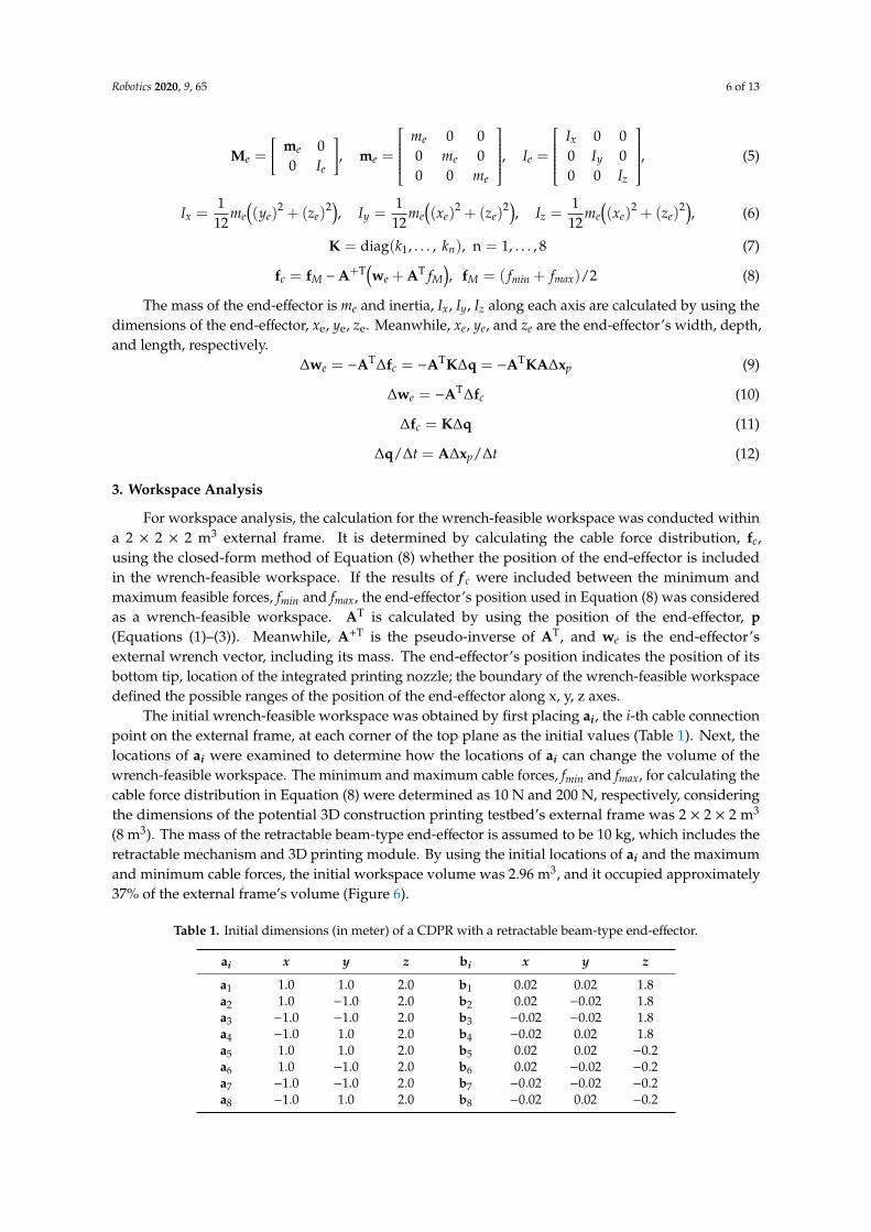
(8 m3). The mass of the retractable beam-type end-effector is assumed to be 10 kg, which includes theretractable mechanism and 3D printing module. By using the initial locations of ai and the maximumand minimum cable forces, the initial workspace volume was 2.96 m3, and it occupied approximately37% of the external frame’s volume (Figure 6).
Table 1. Initial dimensions (in meter) of a CDPR with a retractable beam-type end-effector.
ai x y z bi x y z
a1 1.0 1.0 2.0 b1 0.02 0.02 1.8a2 1.0 −1.0 2.0 b2 0.02 −0.02 1.8a3 −1.0 −1.0 2.0 b3 −0.02 −0.02 1.8a4 −1.0 1.0 2.0 b4 −0.02 0.02 1.8a5 1.0 1.0 2.0 b5 0.02 0.02 −0.2a6 1.0 −1.0 2.0 b6 0.02 −0.02 −0.2a7 −1.0 −1.0 2.0 b7 −0.02 −0.02 −0.2a8 −1.0 1.0 2.0 b8 −0.02 0.02 −0.2
Robotics 2020, 9, 65 7 of 13Robotics 2020, 9, x FOR PEER REVIEW 7 of 13
(a) (b)
Figure 6. Wrench-feasible workspace (red lines) with the ai (blue dots), bi (magenta dots), and the
external frame (cyan lines) on (a) initial wrench-feasible workspace with the initial locations of ai and
bi and (b) improved wrench-feasible workspace when distances between the closest ai are 0.0283 m.
Changes in volume were observed at the locations of ai varied along the horizontal edges of the
external frame’s top plane (Table 2). The variations of ai are limited along the edges of the top plane
to avoid cable interference with an object by maintaining cable connections (Figure 4). The
workspace’s volume decreased as soon as the distance between the neighboring ai lengthened
(Figure 6). When determining the locations of ai, considering the volume decrease in Figure 7, the
minimum distance around 0.1 m was used to prevent the two 0.04 m-diameter guide pulleys from
colliding or overlapping during installation. Thus, the locations of ai were 0.1 m, and the corresponding
x, y, and z coordinates are shown in Table 3.
Table 2. The locations of ai when the distances are 0.0283 (x = 0.98) and 0.212 (x = 0.85), respectively.
ai x y z ai x y z
a1 0.98 1.0 2.0 a1 0.85 1.0 2.0
a2 0.98 −1.0 2.0 a2 0.85 −1.0 2.0
a3 −0.98 −1.0 2.0 a3 −0.85 −1.0 2.0
a4 −0.98 1.0 2.0 a4 −0.85 1.0 2.0
a5 1.0 0.98 2.0 a5 1.0 0.85 2.0
a6 1.0 −0.98 2.0 a6 1.0 −0.85 2.0
a7 −1.0 −0.98 2.0 a7 −1.0 −0.85 2.0
a8 −1.0 0.98 2.0 a8 −1.0 0.85 2.0
Figure 6. Wrench-feasible workspace (red lines) with the ai (blue dots), bi (magenta dots), and theexternal frame (cyan lines) on (a) initial wrench-feasible workspace with the initial locations of ai andbi and (b) improved wrench-feasible workspace when distances between the closest ai are 0.0283 m.
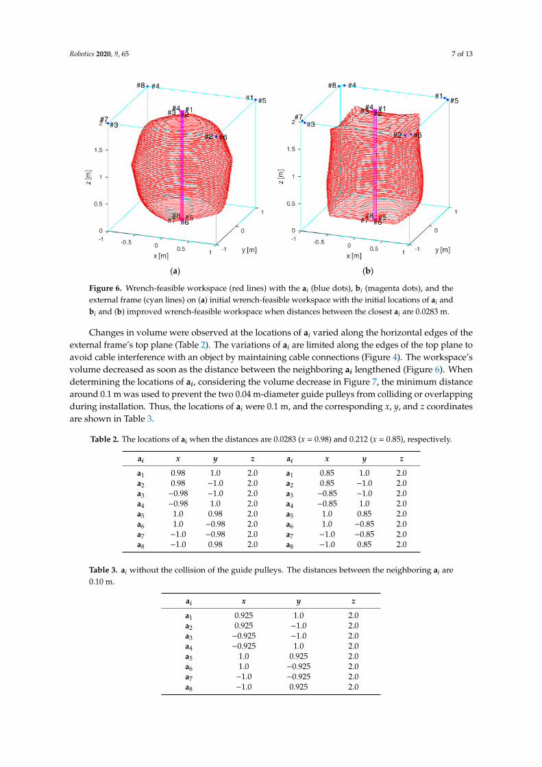
Changes in volume were observed at the locations of ai varied along the horizontal edges of theexternal frame’s top plane (Table 2). The variations of ai are limited along the edges of the top plane toavoid cable interference with an object by maintaining cable connections (Figure 4). The workspace’svolume decreased as soon as the distance between the neighboring ai lengthened (Figure 6). Whendetermining the locations of ai, considering the volume decrease in Figure 7, the minimum distancearound 0.1 m was used to prevent the two 0.04 m-diameter guide pulleys from colliding or overlappingduring installation. Thus, the locations of ai were 0.1 m, and the corresponding x, y, and z coordinatesare shown in Table 3.
Table 2. The locations of ai when the distances are 0.0283 (x = 0.98) and 0.212 (x = 0.85), respectively.
ai x y z ai x y z
a1 0.98 1.0 2.0 a1 0.85 1.0 2.0a2 0.98 −1.0 2.0 a2 0.85 −1.0 2.0a3 −0.98 −1.0 2.0 a3 −0.85 −1.0 2.0a4 −0.98 1.0 2.0 a4 −0.85 1.0 2.0a5 1.0 0.98 2.0 a5 1.0 0.85 2.0a6 1.0 −0.98 2.0 a6 1.0 −0.85 2.0a7 −1.0 −0.98 2.0 a7 −1.0 −0.85 2.0a8 −1.0 0.98 2.0 a8 −1.0 0.85 2.0
Table 3. ai without the collision of the guide pulleys. The distances between the neighboring ai are0.10 m.
ai x y z
a1 0.925 1.0 2.0a2 0.925 −1.0 2.0a3 −0.925 −1.0 2.0a4 −0.925 1.0 2.0a5 1.0 0.925 2.0a6 1.0 −0.925 2.0a7 −1.0 −0.925 2.0a8 −1.0 0.925 2.0
Robotics 2020, 9, 65 8 of 13Robotics 2020, 9, x FOR PEER REVIEW 8 of 13
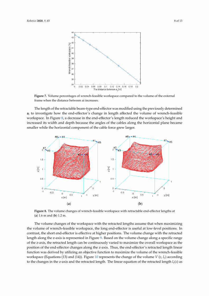
Figure 7. Volume percentages of wrench-feasible workspace compared to the volume of the external
frame when the distance between ai increases.
Table 3. ai without the collision of the guide pulleys. The distances between the neighboring ai are
0.10 m.
ai x y z
a1 0.925 1.0 2.0
a2 0.925 −1.0 2.0
a3 −0.925 −1.0 2.0
a4 −0.925 1.0 2.0
a5 1.0 0.925 2.0
a6 1.0 −0.925 2.0
a7 −1.0 −0.925 2.0
a8 −1.0 0.925 2.0
The length of the retractable beam-type end-effector was modified using the previously
determined ai to investigate how the end-effector’s change in length affected the volume of wrench-
feasible workspace. In Figure 8, a decrease in the end-effector’s length reduced the workspace’s
height and increased its width and depth because the angles of the cables along the horizontal plane
became smaller while the horizontal component of the cable force grew larger.
The volume changes of the workspace with the retracted lengths assume that when maximizing
the volume of wrench-feasible workspace, the long end-effector is useful at low-level positions. In
contrast, the short end-effector is effective at higher positions. The volume change with the retracted
length along the z-axis is represented in Figure 9. Based on the volume change along a specific range
of the z-axis, the retracted length can be continuously varied to maximize the overall workspace as
the position of the end-effector changes along the z-axis. Thus, the end-effector’s retracted length
linear function was derived by utilizing an objective function to maximize the volume of the wrench-
feasible workspace (Equations (13) and (14)). Figure 10 represents the change of the volume V (z, le)
according to the changes in the z-axis and the retracted length. The linear equation of the retracted
length le(z) as a function of the z-axis position is derived as Equation (15) by the linear approximation
of the points of maximum volume in Figure 10.
Figure 7. Volume percentages of wrench-feasible workspace compared to the volume of the externalframe when the distance between ai increases.
The length of the retractable beam-type end-effector was modified using the previously determinedai to investigate how the end-effector’s change in length affected the volume of wrench-feasibleworkspace. In Figure 8, a decrease in the end-effector’s length reduced the workspace’s height andincreased its width and depth because the angles of the cables along the horizontal plane becamesmaller while the horizontal component of the cable force grew larger.Robotics 2020, 9, x FOR PEER REVIEW 9 of 13
(a) (b)
Figure 8. The volume changes of wrench-feasible workspace with retractable end-effector lengths at
(a) 1.6 m and (b) 1.2 m.
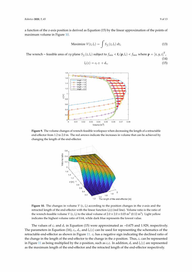
Figure 9. The volume changes of wrench-feasible workspace when decreasing the length of a
retractable end-effector from 1.2 to 2.0 m. The red arrows indicate the increases in volume that can be
achieved by changing the length of the end-effector.
Maximize 𝑉(𝑧, 𝑙𝑒) = ∫ 𝑆𝑓𝑐(𝑧, 𝑙𝑒) 𝑑𝑧, (13)
The wrench − feasible area of 𝑥𝑦 plane 𝑆𝑓𝑐(𝑧, 𝑙𝑒) subject to 𝑓𝑚𝑖𝑛 < 𝐟𝑐(𝐩, 𝑙𝑒) < 𝑓𝑚𝑎𝑥
where 𝐩 = [𝑥, 𝑦, 𝑧]T, (14)
𝑙𝑒(𝑧) = 𝑐𝑟 𝑧 + 𝑑𝑟 , (15)
Figure 8. The volume changes of wrench-feasible workspace with retractable end-effector lengths at(a) 1.6 m and (b) 1.2 m.
The volume changes of the workspace with the retracted lengths assume that when maximizingthe volume of wrench-feasible workspace, the long end-effector is useful at low-level positions. Incontrast, the short end-effector is effective at higher positions. The volume change with the retractedlength along the z-axis is represented in Figure 9. Based on the volume change along a specific rangeof the z-axis, the retracted length can be continuously varied to maximize the overall workspace as theposition of the end-effector changes along the z-axis. Thus, the end-effector’s retracted length linearfunction was derived by utilizing an objective function to maximize the volume of the wrench-feasibleworkspace (Equations (13) and (14)). Figure 10 represents the change of the volume V (z, le) accordingto the changes in the z-axis and the retracted length. The linear equation of the retracted length le(z) as
Robotics 2020, 9, 65 9 of 13
a function of the z-axis position is derived as Equation (15) by the linear approximation of the points ofmaximum volume in Figure 10.
Maximize V(z, le) =∫
S fc(z, le) dz, (13)
The wrench− feasible area of xy plane S fc(z, le) subject to fmin < fc(p, le) < fmax where p = [x, y, z]T,(14)
le(z) = cr z + dr, (15)
Robotics 2020, 9, x FOR PEER REVIEW 9 of 13
(a) (b)
Figure 8. The volume changes of wrench-feasible workspace with retractable end-effector lengths at
(a) 1.6 m and (b) 1.2 m.
Figure 9. The volume changes of wrench-feasible workspace when decreasing the length of a
retractable end-effector from 1.2 to 2.0 m. The red arrows indicate the increases in volume that can be
achieved by changing the length of the end-effector.
Maximize 𝑉(𝑧, 𝑙𝑒) = ∫ 𝑆𝑓𝑐(𝑧, 𝑙𝑒) 𝑑𝑧, (13)
The wrench − feasible area of 𝑥𝑦 plane 𝑆𝑓𝑐(𝑧, 𝑙𝑒) subject to 𝑓𝑚𝑖𝑛 < 𝐟𝑐(𝐩, 𝑙𝑒) < 𝑓𝑚𝑎𝑥
where 𝐩 = [𝑥, 𝑦, 𝑧]T, (14)
𝑙𝑒(𝑧) = 𝑐𝑟 𝑧 + 𝑑𝑟 , (15)
Figure 9. The volume changes of wrench-feasible workspace when decreasing the length of a retractableend-effector from 1.2 to 2.0 m. The red arrows indicate the increases in volume that can be achieved bychanging the length of the end-effector.Robotics 2020, 9, x FOR PEER REVIEW 10 of 13
Figure 10. The changes in volume V (z, le) according to the position changes in the z-axis and the
retracted length of the end-effector with the linear function le(z) (red line). Volume ratio is the ratio of
the wrench-feasible volume V (z, le) to the ideal volume of 2.0 × 2.0 × 0.03 m3 (0.12 m3). Light yellow
indicates the highest volume ratio of 0.64, while dark blue represents the lowest value.
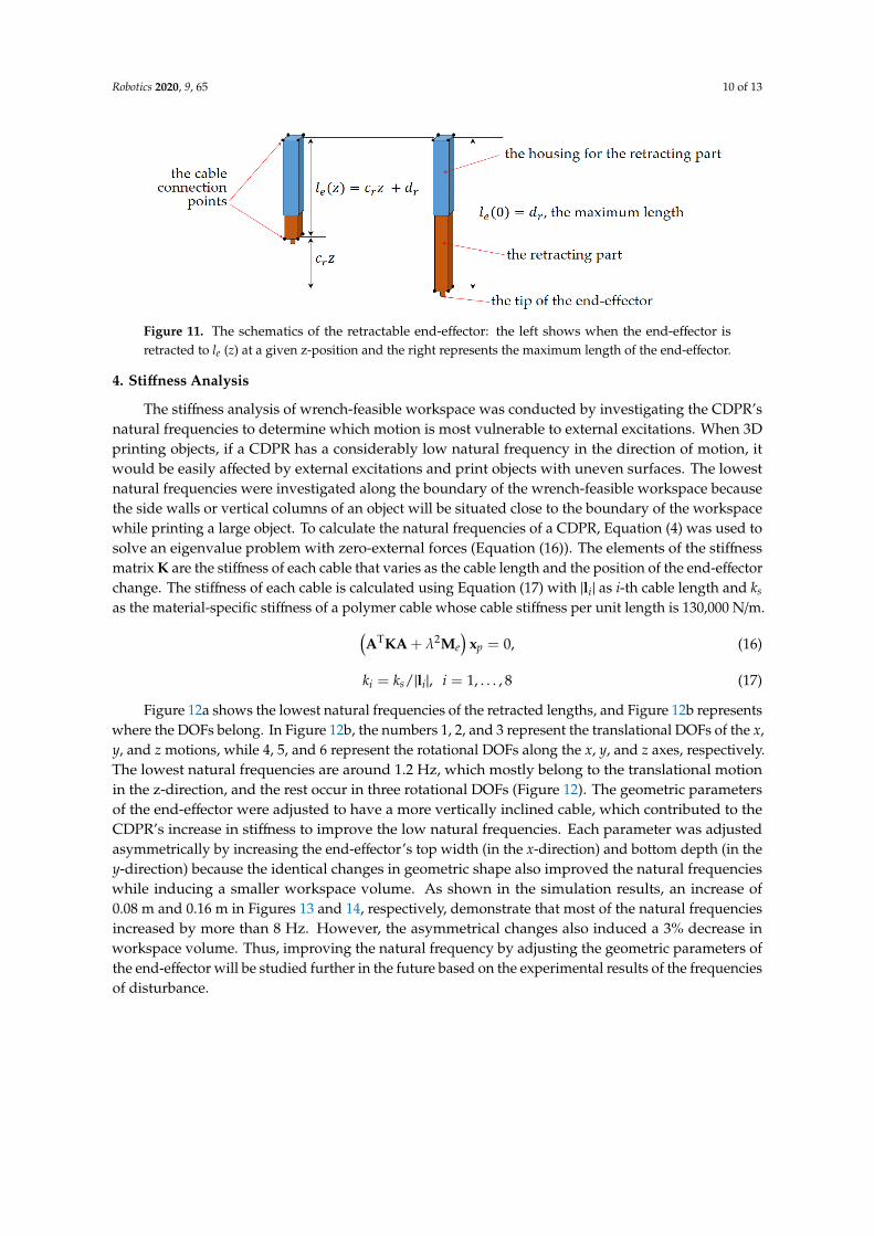
The values of cr and dr in Equation (15) were approximated as −0.675 and 1.929, respectively. The
parameters in Equation (16), 𝑐𝑟 , 𝑑𝑟 , and 𝑙𝑒(𝑧) can be used for representing the schematics of the
retractable end-effector as shown in Figure 11. 𝑐𝑟 has a negative sign indicating the declined ratio of
the change in the length of the end-effector to the change in the z-position. Thus, 𝑐𝑟 can be represented
in Figure 11 as being multiplied by the z-position, such as 𝑐𝑟𝑧 . In addition, 𝑑𝑟 and 𝑙𝑒(𝑧) are
represented as the maximum length of the end-effector and the retracted length of the end-effector
respectively.
Figure 11. The schematics of the retractable end-effector: the left shows when the end-effector is
retracted to le (z) at a given z-position and the right represents the maximum length of the end-effector.
4. Stiffness Analysis
The stiffness analysis of wrench-feasible workspace was conducted by investigating the CDPR’s
natural frequencies to determine which motion is most vulnerable to external excitations. When 3D
printing objects, if a CDPR has a considerably low natural frequency in the direction of motion, it
would be easily affected by external excitations and print objects with uneven surfaces. The lowest
natural frequencies were investigated along the boundary of the wrench-feasible workspace because
the side walls or vertical columns of an object will be situated close to the boundary of the workspace
while printing a large object. To calculate the natural frequencies of a CDPR, Equation (4) was used
to solve an eigenvalue problem with zero-external forces (Equation (16)). The elements of the stiffness
matrix K are the stiffness of each cable that varies as the cable length and the position of the
end-effector change. The stiffness of each cable is calculated using Equation (17) with |li| as i-th cable
length and ks as the material-specific stiffness of a polymer cable whose cable stiffness per unit length
is 130,000 N/m.
Figure 10. The changes in volume V (z, le) according to the position changes in the z-axis and theretracted length of the end-effector with the linear function le(z) (red line). Volume ratio is the ratio ofthe wrench-feasible volume V (z, le) to the ideal volume of 2.0 × 2.0 × 0.03 m3 (0.12 m3). Light yellowindicates the highest volume ratio of 0.64, while dark blue represents the lowest value.
The values of cr and dr in Equation (15) were approximated as −0.675 and 1.929, respectively.The parameters in Equation (16), cr, dr, and le(z) can be used for representing the schematics of theretractable end-effector as shown in Figure 11. cr has a negative sign indicating the declined ratio ofthe change in the length of the end-effector to the change in the z-position. Thus, cr can be representedin Figure 11 as being multiplied by the z-position, such as crz. In addition, dr and le(z) are representedas the maximum length of the end-effector and the retracted length of the end-effector respectively.
Robotics 2020, 9, 65 10 of 13
Robotics 2020, 9, x FOR PEER REVIEW 10 of 13
Figure 10. The changes in volume V (z, le) according to the position changes in the z-axis and the
retracted length of the end-effector with the linear function le(z) (red line). Volume ratio is the ratio of
the wrench-feasible volume V (z, le) to the ideal volume of 2.0 × 2.0 × 0.03 m3 (0.12 m3). Light yellow
indicates the highest volume ratio of 0.64, while dark blue represents the lowest value.
The values of cr and dr in Equation (15) were approximated as −0.675 and 1.929, respectively. The
parameters in Equation (16), 𝑐𝑟 , 𝑑𝑟 , and 𝑙𝑒(𝑧) can be used for representing the schematics of the
retractable end-effector as shown in Figure 11. 𝑐𝑟 has a negative sign indicating the declined ratio of
the change in the length of the end-effector to the change in the z-position. Thus, 𝑐𝑟 can be represented
in Figure 11 as being multiplied by the z-position, such as 𝑐𝑟𝑧 . In addition, 𝑑𝑟 and 𝑙𝑒(𝑧) are
represented as the maximum length of the end-effector and the retracted length of the end-effector
respectively.
Figure 11. The schematics of the retractable end-effector: the left shows when the end-effector is
retracted to le (z) at a given z-position and the right represents the maximum length of the end-effector.
4. Stiffness Analysis
The stiffness analysis of wrench-feasible workspace was conducted by investigating the CDPR’s
natural frequencies to determine which motion is most vulnerable to external excitations. When 3D
printing objects, if a CDPR has a considerably low natural frequency in the direction of motion, it
would be easily affected by external excitations and print objects with uneven surfaces. The lowest
natural frequencies were investigated along the boundary of the wrench-feasible workspace because
the side walls or vertical columns of an object will be situated close to the boundary of the workspace
while printing a large object. To calculate the natural frequencies of a CDPR, Equation (4) was used
to solve an eigenvalue problem with zero-external forces (Equation (16)). The elements of the stiffness
matrix K are the stiffness of each cable that varies as the cable length and the position of the
end-effector change. The stiffness of each cable is calculated using Equation (17) with |li| as i-th cable
length and ks as the material-specific stiffness of a polymer cable whose cable stiffness per unit length
is 130,000 N/m.
Figure 11. The schematics of the retractable end-effector: the left shows when the end-effector isretracted to le (z) at a given z-position and the right represents the maximum length of the end-effector.
4. Stiffness Analysis
The stiffness analysis of wrench-feasible workspace was conducted by investigating the CDPR’snatural frequencies to determine which motion is most vulnerable to external excitations. When 3Dprinting objects, if a CDPR has a considerably low natural frequency in the direction of motion, itwould be easily affected by external excitations and print objects with uneven surfaces. The lowestnatural frequencies were investigated along the boundary of the wrench-feasible workspace becausethe side walls or vertical columns of an object will be situated close to the boundary of the workspacewhile printing a large object. To calculate the natural frequencies of a CDPR, Equation (4) was used tosolve an eigenvalue problem with zero-external forces (Equation (16)). The elements of the stiffnessmatrix K are the stiffness of each cable that varies as the cable length and the position of the end-effectorchange. The stiffness of each cable is calculated using Equation (17) with |li| as i-th cable length and ks
as the material-specific stiffness of a polymer cable whose cable stiffness per unit length is 130,000 N/m.(ATKA + λ2Me
)xp = 0, (16)
ki = ks/|li|, i = 1, . . . , 8 (17)
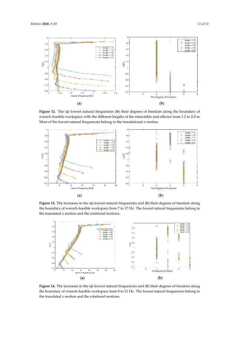
Figure 12a shows the lowest natural frequencies of the retracted lengths, and Figure 12b representswhere the DOFs belong. In Figure 12b, the numbers 1, 2, and 3 represent the translational DOFs of the x,y, and z motions, while 4, 5, and 6 represent the rotational DOFs along the x, y, and z axes, respectively.The lowest natural frequencies are around 1.2 Hz, which mostly belong to the translational motionin the z-direction, and the rest occur in three rotational DOFs (Figure 12). The geometric parametersof the end-effector were adjusted to have a more vertically inclined cable, which contributed to theCDPR’s increase in stiffness to improve the low natural frequencies. Each parameter was adjustedasymmetrically by increasing the end-effector’s top width (in the x-direction) and bottom depth (in they-direction) because the identical changes in geometric shape also improved the natural frequencieswhile inducing a smaller workspace volume. As shown in the simulation results, an increase of0.08 m and 0.16 m in Figures 13 and 14, respectively, demonstrate that most of the natural frequenciesincreased by more than 8 Hz. However, the asymmetrical changes also induced a 3% decrease inworkspace volume. Thus, improving the natural frequency by adjusting the geometric parameters ofthe end-effector will be studied further in the future based on the experimental results of the frequenciesof disturbance.
Robotics 2020, 9, 65 11 of 13
Robotics 2020, 9, x FOR PEER REVIEW 11 of 13
(𝐀T𝐊𝐀 + 𝜆2𝐌𝑒) 𝐱𝑝 = 𝟎, (16)
𝑘𝑖 = 𝑘𝑠/|𝐥𝑖|, 𝑖 = 1, … ,8 (17)
Figure 12a shows the lowest natural frequencies of the retracted lengths, and Figure 12b
represents where the DOFs belong. In Figure 12b, the numbers 1, 2, and 3 represent the translational
DOFs of the x, y, and z motions, while 4, 5, and 6 represent the rotational DOFs along the x, y, and z
axes, respectively. The lowest natural frequencies are around 1.2 Hz, which mostly belong to the
translational motion in the z-direction, and the rest occur in three rotational DOFs (Figure 12). The
geometric parameters of the end-effector were adjusted to have a more vertically inclined cable,
which contributed to the CDPR’s increase in stiffness to improve the low natural frequencies. Each
parameter was adjusted asymmetrically by increasing the end-effector’s top width (in the x-direction)
and bottom depth (in the y-direction) because the identical changes in geometric shape also improved
the natural frequencies while inducing a smaller workspace volume. As shown in the simulation
results, an increase of 0.08 m and 0.16 m in Figures 13 and 14, respectively, demonstrate that most of
the natural frequencies increased by more than 8 Hz. However, the asymmetrical changes also
induced a 3% decrease in workspace volume. Thus, improving the natural frequency by adjusting
the geometric parameters of the end-effector will be studied further in the future based on the
experimental results of the frequencies of disturbance.
(a) (b)
Figure 12. The (a) lowest natural frequencies (b) their degrees of freedom along the boundary of
wrench-feasible workspace with the different lengths of the retractable end-effector from 1.2 to 2.0 m.
Most of the lowest natural frequencies belong to the translational z motion.
(a) (b)
Figure 12. The (a) lowest natural frequencies (b) their degrees of freedom along the boundary ofwrench-feasible workspace with the different lengths of the retractable end-effector from 1.2 to 2.0 m.Most of the lowest natural frequencies belong to the translational z motion.
Robotics 2020, 9, x FOR PEER REVIEW 11 of 13
(𝐀T𝐊𝐀 + 𝜆2𝐌𝑒) 𝐱𝑝 = 𝟎, (16)
𝑘𝑖 = 𝑘𝑠/|𝐥𝑖|, 𝑖 = 1, … ,8 (17)
Figure 12a shows the lowest natural frequencies of the retracted lengths, and Figure 12b
represents where the DOFs belong. In Figure 12b, the numbers 1, 2, and 3 represent the translational
DOFs of the x, y, and z motions, while 4, 5, and 6 represent the rotational DOFs along the x, y, and z
axes, respectively. The lowest natural frequencies are around 1.2 Hz, which mostly belong to the
translational motion in the z-direction, and the rest occur in three rotational DOFs (Figure 12). The
geometric parameters of the end-effector were adjusted to have a more vertically inclined cable,
which contributed to the CDPR’s increase in stiffness to improve the low natural frequencies. Each
parameter was adjusted asymmetrically by increasing the end-effector’s top width (in the x-direction)
and bottom depth (in the y-direction) because the identical changes in geometric shape also improved
the natural frequencies while inducing a smaller workspace volume. As shown in the simulation
results, an increase of 0.08 m and 0.16 m in Figures 13 and 14, respectively, demonstrate that most of
the natural frequencies increased by more than 8 Hz. However, the asymmetrical changes also
induced a 3% decrease in workspace volume. Thus, improving the natural frequency by adjusting
the geometric parameters of the end-effector will be studied further in the future based on the
experimental results of the frequencies of disturbance.
(a) (b)
Figure 12. The (a) lowest natural frequencies (b) their degrees of freedom along the boundary of
wrench-feasible workspace with the different lengths of the retractable end-effector from 1.2 to 2.0 m.
Most of the lowest natural frequencies belong to the translational z motion.
(a) (b)
Figure 13. The increases in the (a) lowest natural frequencies and (b) their degrees of freedom alongthe boundary of wrench-feasible workspace from 7 to 17 Hz. The lowest natural frequencies belong tothe translated z motion and the rotational motions.
Robotics 2020, 9, x FOR PEER REVIEW 12 of 13
Figure 13. The increases in the (a) lowest natural frequencies and (b) their degrees of freedom along
the boundary of wrench-feasible workspace from 7 to 17 Hz. The lowest natural frequencies belong
to the translated z motion and the rotational motions.
(a) (b)
Figure 14. The increases in the (a) lowest natural frequencies and (b) their degrees of freedom along
the boundary of wrench-feasible workspace from 8 to 21 Hz. The lowest natural frequencies belong
to the translated z motion and the rotational motions.
5. Conclusions and Future Works
In this study, wrench-feasible workspace and stiffness analyses were conducted to investigate
the effectiveness of a retractable beam-type end-effector for 3D construction printing. Cable
connection types and the locations of cable connection points were determined to minimize cable
interference with the printed objects within the workspace and maximize workspace volume,
respectively. The wrench-feasible workspace can be expanded by varying the length of the retractable
end-effector over the workspace, while the stiffness analysis shows that the lowest natural
frequencies can be improved by adjusting the geometric parameters of the end-effector while
considering disturbance frequencies.
In the future, the retractable beam-type end-effector for a 3D printing CDPR will be
implemented. The CDPR testbed with a retractable end-effector’s performance will also be
investigated in terms of cable interference and the size and quality of various 3D printed objects.
Funding: This research was funded by the Basic Science Research Program through the National Research
Foundation of Korea (NRF) and by the Ministry of Education, grant number NRF-2018R1C1B5086505.
Conflicts of Interest: The author declares no conflicts of interest.
References
1. Duda, T.; Raghavan, L. 3D metal printing technology. IFAC-PapersOnline 2016, 49, 103–110.
2. Buchanan, C.; Gardner, L. Metal 3D printing in construction: A review of methods, research, applications,
opportunities and challenges. Eng. Struct. 2019, 180, 332–348.
3. Gupta, S.; Bissoyi, A.; Bit, A. A review on 3D printable techniques for tissue engineering. Bionanoscience
2018, 8, 868–883.
4. Valente, M.; Sibai, A.; Sambucci, M. Extrusion-based additive manufacturing of concrete products:
Revolutionizing and remodeling the construction industry. J. Compos. Sci. 2019, 3, 88.
5. Mechtcherine, V.; Nerella, V.; Will, F.; Näther, M.; Otto, J.; Krause, M. Large-scale digital concrete
construction—CONPrint3D concept for on-site, monolithic 3D-printing. Autom. Constr. 2019, 107, 102933.
6. Izard, J.; Dubor, A.; Hervé, P.; Cabay, E.; Cull, D.; Rodriguez, M.; Barrado, M. Large-scale 3D printing with
cable-driven parallel robots. Constr. Robot. 2017, 1, 69–76.
7. Zhong, Y.; Qian, S. A Cable-Driven Parallel Robot for 3D Printing. In Proceedings of the 2018 IEEE
International Conference on Mechatronics, Robotics and Automation (ICMRA), Hefei, China, 18–21 May
2018; IEEE: Piscataway, NJ, USA; pp. 199–203.
Figure 14. The increases in the (a) lowest natural frequencies and (b) their degrees of freedom alongthe boundary of wrench-feasible workspace from 8 to 21 Hz. The lowest natural frequencies belong tothe translated z motion and the rotational motions.
Robotics 2020, 9, 65 12 of 13
5. Conclusions and Future Works
In this study, wrench-feasible workspace and stiffness analyses were conducted to investigate theeffectiveness of a retractable beam-type end-effector for 3D construction printing. Cable connectiontypes and the locations of cable connection points were determined to minimize cable interferencewith the printed objects within the workspace and maximize workspace volume, respectively. Thewrench-feasible workspace can be expanded by varying the length of the retractable end-effector overthe workspace, while the stiffness analysis shows that the lowest natural frequencies can be improvedby adjusting the geometric parameters of the end-effector while considering disturbance frequencies.
In the future, the retractable beam-type end-effector for a 3D printing CDPR will be implemented.The CDPR testbed with a retractable end-effector’s performance will also be investigated in terms ofcable interference and the size and quality of various 3D printed objects.
Funding: This research was funded by the Basic Science Research Program through the National ResearchFoundation of Korea (NRF) and by the Ministry of Education, grant number NRF-2018R1C1B5086505.
Conflicts of Interest: The author declares no conflict of interest.
References
1. Duda, T.; Raghavan, L. 3D metal printing technology. IFAC-PapersOnline 2016, 49, 103–110. [CrossRef]2. Buchanan, C.; Gardner, L. Metal 3D printing in construction: A review of methods, research, applications,
opportunities and challenges. Eng. Struct. 2019, 180, 332–348. [CrossRef]3. Gupta, S.; Bissoyi, A.; Bit, A. A review on 3D printable techniques for tissue engineering. Bionanoscience 2018,
8, 868–883. [CrossRef]4. Valente, M.; Sibai, A.; Sambucci, M. Extrusion-based additive manufacturing of concrete products:
Revolutionizing and remodeling the construction industry. J. Compos. Sci. 2019, 3, 88. [CrossRef]5. Mechtcherine, V.; Nerella, V.; Will, F.; Näther, M.; Otto, J.; Krause, M. Large-scale digital concrete
construction—CONPrint3D concept for on-site, monolithic 3D-printing. Autom. Constr. 2019, 107, 102933.[CrossRef]
6. Izard, J.; Dubor, A.; Hervé, P.; Cabay, E.; Cull, D.; Rodriguez, M.; Barrado, M. Large-scale 3D printing withcable-driven parallel robots. Constr. Robot. 2017, 1, 69–76. [CrossRef]
7. Zhong, Y.; Qian, S. A Cable-Driven Parallel Robot for 3D Printing. In Proceedings of the 2018 IEEEInternational Conference on Mechatronics, Robotics and Automation (ICMRA), Hefei, China, 18–21 May2018; IEEE: Piscataway, NJ, USA; pp. 199–203.
8. Qian, S.; Bao, K.; Wang, N.; Zi, B. Kinematic calibration of a cable-driven parallel robot for 3D printing.Sensors 2018, 18, 2898. [CrossRef] [PubMed]
9. Bosscher, P.; Williams, R.; Bryson, L.; Castro-Lacouture, D. Cable-suspended robotic contour crafting system.Autom. Constr. 2007, 17, 45–55. [CrossRef]
10. Barnett, E.; Gosselin, C. Large-scale 3D printing with a cable-suspended robot. Addit. Manuf. 2015, 7, 27–44.[CrossRef]
11. Zhang, Y.; Zhang, Y.; Dai, X.; Yang, Y. Workspace Analysis of a Novel 6-DOF Cable-Driven Parallel Robot. InProceedings of the 2009 IEEE International Conference on Robotics and Biomimetics (ROBIO), Guilin, China,19–23 December 2009; IEEE: Pistacaway, NJ, USA, 2009; pp. 2403–2408.
12. Gagliardini, L.; Gouttefarde, M.; Caro, S. Determination of a dynamic feasible workspace for cable-drivenparallel robots. In Advances in Robot Kinematics; Lennarcic, J., Siciliano, B., Eds.; Springer InternationalPublishing: New York, NY, USA, 2016; Volume 4, pp. 361–370.
13. Heo, J.-M.; Park, B.-J.; Park, J.-O.; Kim, C.-S.; Jung, J.; Park, K.-S. Workspace and stability analysis of a6-DOF cable-driven parallel robot using frequency-based variable constraints. J. Mech. Sci. Technol. 2018, 32,1345–1356. [CrossRef]
14. Boumann, R.; Bruckmann, T. Real-time cable force calculation beyond the wrench-feasible workspace.Robotics 2020, 9, 41. [CrossRef]
15. Yuan, H.; Courteille, E.; Deblaise, D. Static and dynamic stiffness analyses of cable-driven parallel robotswith non-negligible cable mass and elasticity. Mech. Mach. Theory 2015, 85, 64–81. [CrossRef]
Robotics 2020, 9, 65 13 of 13
16. Surdilovic, D.; Radojicic, J.; Krüger, J. Geometric stiffness analysis of wire robots: A mechanical approach.In Cable-Driven Parallel Robots. Mechanisms and Machine Science; Bruckmann, T., Pott, A., Eds.; Springer:Berlin/Heidelberg, Germany, 2013; Volume 12, pp. 389–404.
17. Kraus, W. Force Control of Cable-Driven Parallel Robots. Ph.D. Thesis, University of Stuttgart, Stuttgart,Germany, 2015.
18. Williams, R.L., II; Xin, M.; Bosscher, P. Contour-crafting-cartesian-cable robot system concepts: Workspaceand stiffness comparisons. In Proceedings of the ASME International Design Technical Conferences, Brooklyn,NY, USA, 3–6 August 2018; ASME: New York, NY, USA, 2018; pp. 31–38.
19. Pott, A. Cable-Driven Parallel Robots: Theory and Application, 1st ed.; Springer International Publishing AG:Cham, Switzerland, 2018; pp. 89–91.
© 2020 by the author. Licensee MDPI, Basel, Switzerland. This article is an open accessarticle distributed under the terms and conditions of the Creative Commons Attribution(CC BY) license (http://creativecommons.org/licenses/by/4.0/).