Industry Leader Since 1969Made in the USA
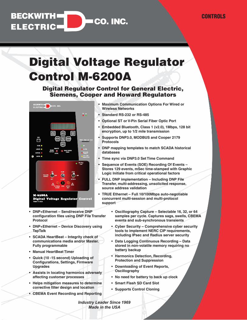
Digital Voltage Regulator Control M-6200A
Digital Regulator Control for General Electric, Siemens, Cooper and Howard Regulators
CONTROLS
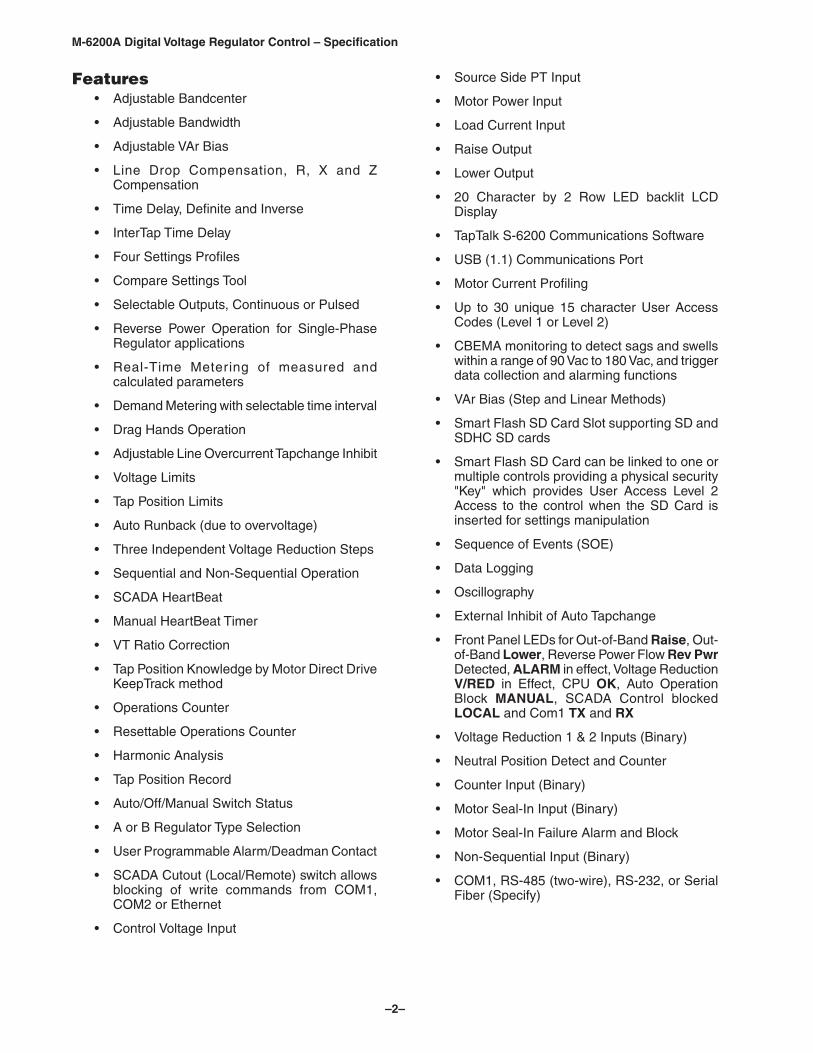
• Maximum Communication Options For Wired or Wireless Networks
• Standard RS-232 or RS-485
• Optional ST or V-Pin Serial Fiber Optic Port
• Embedded Bluetooth, Class 1 (v2.0), 1Mbps, 128 bit encryption, up to 1/2 mile transmission
• Supports DNP3.0, MODBUS and Cooper 2179 Protocols
• DNP mapping templates to match SCADA historical databases
• Time sync via DNP3.0 Set Time Command
• Sequence of Events (SOE) Recording Of Events – Stores 129 events, mSec time-stamped with Graphic Logic Initiate from critical operational factors
• FULL DNP implementation – Including DNP File Transfer, multi-addressing, unsolicited response, source address validation
• TRUE Ethernet – Full 10/100Mbps auto-negotiable concurrent multi-session and multi-protocol support
• DNP+Ethernet – Send/receive DNP configuration files using DNP File Transfer Protocol
• DNP+Ethernet – Device Discovery using TapTalk
• SCADA HeartBeat – Integrity check of communications media and/or Master. Fully programmable
• Manual HeartBeat Timer
• Quick (10 -15 second) Uploading of Configurations, Settings, Firmware Upgrades
• Assists in locating harmonics adversely affecting customer processes
• Helps mitigation measures to determine corrective filter design and location
• CBEMA Event Recording and Reporting
• Oscillography Capture – Selectable 16, 32, or 64 samples per cycle. Captures sags, swells, CBEMA events and sub-synchronous transients
• Cyber Security – Comprehensive cyber security tools to implement NERC CIP requirements, including IPsec and Radius server security
• Data Logging Continuous Recording – Data stored in non-volatile memory requiring no battery backup
• Harmonics Detection, Recording, Protection and Suppression
• Downloading of Event Reports, Oscillography
• No need for battery to back up clock
• Smart Flash SD Card Slot
• Supports Control Cloning
–2–
M-6200A Digital Voltage Regulator Control – Specification
Features• Adjustable Bandcenter
• Adjustable Bandwidth
• Adjustable VAr Bias
• Line Drop Compensation, R, X and Z Compensation
• Time Delay, Definite and Inverse
• InterTap Time Delay
• Four Settings Profiles
• Compare Settings Tool
• Selectable Outputs, Continuous or Pulsed
• Reverse Power Operation for Single-Phase Regulator applications
• Real-Time Metering of measured and calculated parameters
• Demand Metering with selectable time interval
• Drag Hands Operation
• Adjustable Line Overcurrent Tapchange Inhibit
• Voltage Limits
• Tap Position Limits
• Auto Runback (due to overvoltage)
• Three Independent Voltage Reduction Steps
• Sequential and Non-Sequential Operation
• SCADA HeartBeat
• Manual HeartBeat Timer
• VT Ratio Correction
• Tap Position Knowledge by Motor Direct Drive KeepTrack method
• Operations Counter
• Resettable Operations Counter
• Harmonic Analysis
• Tap Position Record
• Auto/Off/Manual Switch Status
• A or B Regulator Type Selection
• User Programmable Alarm/Deadman Contact
• SCADA Cutout (Local/Remote) switch allows blocking of write commands from COM1, COM2 or Ethernet
• Control Voltage Input
• Source Side PT Input
• Motor Power Input
• Load Current Input
• Raise Output
• Lower Output
• 20 Character by 2 Row LED backlit LCD Display
• TapTalk S-6200 Communications Software
• USB (1.1) Communications Port
• Motor Current Profiling
• Up to 30 unique 15 character User Access Codes (Level 1 or Level 2)
• CBEMA monitoring to detect sags and swells within a range of 90 Vac to 180 Vac, and trigger data collection and alarming functions
• VAr Bias (Step and Linear Methods)
• Smart Flash SD Card Slot supporting SD and SDHC SD cards
• Smart Flash SD Card can be linked to one or multiple controls providing a physical security "Key" which provides User Access Level 2 Access to the control when the SD Card is inserted for settings manipulation
• Sequence of Events (SOE)
• Data Logging
• Oscillography
• External Inhibit of Auto Tapchange
• Front Panel LEDs for Out-of-Band Raise, Out-of-Band Lower, Reverse Power Flow Rev Pwr Detected, ALARM in effect, Voltage Reduction V/RED in Effect, CPU OK, Auto Operation Block MANUAL, SCADA Control blocked LOCAL and Com1 TX and RX
• Voltage Reduction 1 & 2 Inputs (Binary)
• Neutral Position Detect and Counter
• Counter Input (Binary)
• Motor Seal-In Input (Binary)
• Motor Seal-In Failure Alarm and Block
• Non-Sequential Input (Binary)
• COM1, RS-485 (two-wire), RS-232, or Serial Fiber (Specify)
–3–
M-6200A Digital Voltage Regulator Control – Specification
• Communication Protocols include MODBUS, Secure DNP3.0 (Authentication) and Cooper 2179
• Control Power Back-Up Input – input (+12 Vdc) for backup of Fiber Optic loop-through communication
• One set (3) of spare fuses are included
• Supports Station and Feeder Level DNP addressing in addition to individual addressing for Smart Grid applications
• One pushbutton access to user configurable Wakeup screen for manual data recording with Smart Flash SD Card saving feature
• Run Through Neutral, Automatic Reversing Switch swiping
• Individual Tap Wear Alarm
• User selectable Tapchanger Type
• IEEE 1686 Standard Compliant Cyber Security
• IPsec (Internet Protocol Security)
• RADIUS Client Capability to manage local and remote access to the control
Optional Features• SCAMP (SCADA Controllable Auto/Manual
Pushbutton)
• COM1, Fiber Optic Port (ST or V-pin connectors available with 62.5 and 200 micro fiber supported)
• COM2, RS-232 Communications Port or Bluetooth*• *Bluetooth option is not available in 50 Hz units shipped to locations subject to Radio Equipment Directive RE-D 2014/53/EU. Contact the factory for more information.
• Ethernet Port is available through a RJ-45 jack (10/100 Base-T) or Fiber Optic through ST connectors (100 Base-Fx). These ports support DNP over TCP/IP and MODBUS over TCP/IP
Accessories• M-2026 AC-DC Control Power Backup Supply
• M-2027 Control Power Backup Supply–AC Only
• B-0920 Control Power Backup Harness
• USB Cable
• SD Card (1 GB) for Smart Flash functions
–4–
M-6200A Digital Voltage Regulator Control – Specification
Bandcenter: Adjustable from 100 V to 135 V in 0.1 V increments.
Bandwidth: Adjustable from 1 V to 10 V in 0.1 V increments.
Line Drop Compensation: R and X compensation. Adjustable from -72 V to +72 V in 1 V increments. Z compensation available with adjustment of voltage raise from 0 V to +72 V, in increments of 1 V.
Time Delay: Definite; adjustable from 1 second to 360 seconds, in 1 second increments. Inverse; adjustable from 1 second to 360 seconds, in 1 second increments.
InterTap Time Delay: Used to introduce time delay between tap operations when control is in sequential mode; adjustable from 0 to 60 seconds in 1.0 second increments. Counter input required.
Selectable Outputs: Continuous or pulsed. Normally, an output (raise or lower) signal is maintained when the voltage remains outside the band. A pulsed output length is programmable from 0.2 to 12 seconds, in increments of 0.1 second.
Reverse Power Operation: If Motor Direct Drive KeepTrack is applicable, unit may be set to "Block", "Regulate Forward (Ignore)", "Regulate Reverse", "Return to Neutral", "Regulate Reverse (Measured)" or "Distributed Generation." The Regulate Reverse feature allows separate setpoints and regulation in the reverse direction without the installation of source-side VTs. Distributed Generation allows alternate LDC R and X values to be applied to the control when reverse power is detected. If Motor Direct Drive KeepTrack is disabled, then "Regulate Reverse (Measured)", "Ignore" and "Block" modes are available. Regulate Reverse (Measured) allows the control to switch it’s voltage sensing input from a load side VT to a source side VT if one is available and operate in Reverse Power Mode using that input.
Smart Reverse Power (Auto Determination)
For reverse power conditions requiring more than one reverse power mode depending on the cause of the reverse power condition; either Distributed Generation mode or Regulate In Reverse/Regulate in Reverse Measured. The M-6200A provides two new reverse power modes, "Auto Determination" and "Auto Determination Measured" which allow the control to intelligently choose which reverse power mode applies at the time reverse power is sensed.
CT to VT Phasing Correction: Adjustable from 0° to +330° in 30° increments.
Load Overcurrent Tapchange Inhibit: Adjustable from 50 mA to 640 mA of load current for 200 mA CT.
Voltage Limits, Tap Position Limits, and Runback: Overvoltage and Undervoltage limits are independently adjustable from 95 V to 135 V in 0.1 V increments. Upper and lower tap position limits may be set by user, with tap position knowledge active. An adjustable deadband (above the overvoltage limit) of 1 V to 4 V is available, which is used to set the runback limit.
Voltage Reduction: Three independent steps, each adjustable from 0% to 10% in 0.1% increments of the bandcenter setpoint. Voltage Reduction can be disabled locally and remotely if desired.
Normalizing Voltage: A Normalizing Voltage Multiplier with a range of 0.80 to 1.20 is available to be applied to Meter Out Voltage and displayed in real time as Normalizing Voltage. The purpose of the Normalizing Voltage is to allow the user to overcome differences in the ratio of the PT that the Load Voltage input is using versus the PT the end user or other metering methods are using.
Inhibit of Auto Tapchange: Blocks automatic regulator operation in response to external contact closure or software setting.
Sequential or Non-Sequential Operation: Non-sequential operation resets the time delay upon momentary external contact closure at the non-sequential input.
VT Ratio Correction: VT correction from -15 V to +15 V in 0.1 V increments.
User-Programmable Alarm/Self Test Contact: Alerts operator to one or more of the following system conditions:
• Communication Block • Backup Power Fail • Line Current Limit • Op Count Signal
• Block Raise (Tap) • RTN Fail to Operate • Reverse Power • Leading VAr
• Block Lower (Tap) • Individual Tap Wear • Self Test (Deadman) • Leading Power Factor
• Block Raise (Voltage) • Lagging VAr • Voltage Reduction • Low Current Block
• Block Lower (Voltage) • Lagging Power Factor • Max VAr Bias Duration Lead • Motor Seal-in Failure
• Abnormal Tap Position • LDC/LDZ • Max VAr Bias Duration Lag
Tap Position Knowledge: In most applications, tap position information can be maintained by means of Motor Direct Drive KeepTrack.
–5–
M-6200A Digital Voltage Regulator Control – Specification
Operations Counter: A software counter increments by one count per either an open/close/open contact operation (X1) or an open/close or close/open contact operation (X2), and is preset by the user. A count window mode registers any activity as a valid input within the count window time setting.
Resettable Operations Counter: A second software counter, similar to the operations counter, which may be reset by the user.
Harmonic Analysis: Provides the total harmonic distortion and the harmonic content of the load voltage and current up to the 31st harmonic.
Tap Position Record: Provides a record of the number of times each tap position has been passed through (using TapTalk). The tap position record can be reset by the user.
Tap Wear Settings: Provides the capability to determine tap wear in a regulator's tap change mechanism.
AUTO/OFF/MANUAL Switch Status: Provides the user with the Auto/Off/Manual switch position status through the Comm ports.
A or B Regulator Type: Allows the user to select the type of regulator being used to provide a more accurate source voltage calculation.
SCADA HeartBeat: The purpose of the SCADA HeartBeat feature is to have two sets of settings for the control and switch between these two setting sets based on the presence or absence of SCADA communications (utilizing the DNP protocol) to the control. The SCADA HeartBeat feature can be enabled from TapTalk Communications Software. There are three different types of SCADA HeartBeat modes that can be selected:
• SCADA HeartBeat for transformer control applications (LTC)
• SCADA HeartBeat for regulator control applications (Regulator)
Manual HeartBeat Timer: The Manual HeartBeat Timer feature provides a method to place the control in HeartBeat Manual operation (implemented from Comms only) and automatically place the control back in Auto mode based on a Timer setting (settable only via Comms).
VAr Bias: This feature is intended but not restricted for use with distribution feeders which have switched capacitor banks controlled by Autodaptive Capacitor Controls. Use of VAr Bias allows the M-6200A to coordinate it’s operation with the Autodaptive Control devices on the distribution system in order to minimize losses, smooth the voltage profile and optimize VAr flow.
Tapchanger Type Selection: Provides the user with the ability to set vendor specific regulator configuration settings in TapTalk.
Monitoring/MeteringReal-Time Metering: The following measured and calculated values are available in real-time:
• Primary Voltage • Control Load kVA, or MVA • Raise/Lower Timer
• Primary Source Voltage • Average Compensated Voltage • Intertap Timer
• Primary Current • Normalizing Voltage • Operation Counter
• Primary Watts • Average Load Current • Resettable Counter
• Primary VArs • Power Factor Load, Lead/Lag • Neutral Counter
• Primary VA • Frequency • RTN Status
• Average Load Voltage • Tap Position • Counter towards RTN
• Meter Out Voltage • Drag Hands • RTN Success Counter
• Average Source Voltage
Present Demand: The Present Demand feature captures the maximum values during the specified time interval. Time interval can be selected as 5, 10, 15, 30, or 60 minutes.
• Demand Load Voltage
• Primary Watts
• Primary VA
• Demand Primary Current
• Primary VArs
–6–
M-6200A Digital Voltage Regulator Control – Specification
Demand History (Drag Hands Operation):
The following "drag-hand" values are stored with date and time stamping and are averaged over 32 seconds:
• Min Local Voltage
• Max Local Voltage
The following "drag-hand" values are stored with date and time stamping and are calculated over the demand time interval (5, 10, 15, 30, or 60 minutes) as selected by the user:
• Max Primary Current (Amps)
• Max Primary Watts (kW, or MW)
• Power Factor @ Max VA
• Max Primary VArs (kVAr or MVAr)
• Max Primary VA (kVA or MVA)
Energy Metering:
The following measured values are retained in non-volatile memory. A real time clock is utilized to record a date/time stamp for each quantity to indicate when the period of measurement was initiated.
• Watt Hours Forward (kWh)
• Watt Hours Reverse (kWh)
• VAr Hours Forward (kVArh)
• VAr Hours Reverse (kVArh)
Oscillograph:
The Oscillograph Recorder provides comprehensive data recording (voltage, current, and status input/output signals) for all monitored waveforms (at 16, 32 or 64 samples per cycle). Oscillograph data can be downloaded using the communications ports to any Windows based personal computer running the TapTalk S-6200 Communications Software. Once downloaded, the waveform data can be examined and printed using M-2829 TapPlot Analysis Software which is built into TapTalk. The waveform data is also available in COMTRADE file format.
Sequence of Events:
The Sequence of Events Recorder provides comprehensive time tagged data recording of control parameters that include Voltage, Frequency, Tap Position, Current, Counters and Harmonics. The total number of events that can be recorded is 129. The Sequence of Events Recorder is triggered by user selectable programmable parameter logic or manually by the user.
Data Logging:
The Data Logging feature allows the user to record data internally into nonvolatile memory. The Data Log is saved in Comtrade format. The Data Log can be downloaded utilizing either MODBUS or DNP protocols.
InputsLoad Voltage Input: Nominal 120 Vac, 60 Hz (50 Hz optional); operates properly from 90 Vac to 140 Vac. If set at 60 Hz, the operating system frequency is from 55 to 65 Hz; if set at 50 Hz, the operating system frequency is from 45 to 55 Hz. The burden imposed on the input is 8 VA or less. The unit should be powered from a voltage transformer connected at the controlled voltage bus. The unit will withstand twice the voltage input for one second and four times the voltage input for one cycle.
Motor Power Input: Nominal 120 Vac or 240 Vac, at up to 6 A as required by the load, with no wiring changes required.
Motor Seal-In Input: Receives an input from the Cooper regulator motor holding switch.
Load Current Input: Line drop compensation is provided by a current transformer input with a 0.2 A full scale rating. A Beckwith Electric model M-0121 (5 A to 0.2 A) or M-0169A (5 A or 8.66 A to 0.2 A) Auxiliary Current Transformer is available when required. The burden imposed on the current source is 0.03 VA or less at 200 mA. The input will withstand 480 mA continuous and 4 A for 1 second.
Control Power Backup Input: The standard Control Power Backup Input feature sustains operation of the control in the event of a loss of AC input power to the control. Raise and Lower commands are possible if the control’s motor power remains energized. A DC power supply is required.
Counter Input: The Counter Input detects tap position changes and updates two counters, one presettable and one resettable.
–7–
M-6200A Digital Voltage Regulator Control – Specification
Neutral Tap Position Detect Input: The Neutral Position Detect Input detects the neutral tap position, which assists the Motor Direct Drive KeepTrack tap position function.
Source Voltage Input: Nominal 120 Vac, 60 Hz (50 Hz optional); operates properly from 90 Vac to 140 Vac. If set at 60 Hz, the operating system frequency is from 55 to 65 Hz; if set at 50 Hz, the operating system frequency is from 45 to 55 Hz. The burden imposed on the input is 8 VA or less. The unit should be powered from a voltage transformer connected at the controlled voltage bus. The unit will withstand twice the voltage input for one second and four times the voltage input for one cycle. This input is used with the Reverse Power Measured feature when reverse power operation is desired and a Source Side PT input is available. The control can not display both Load Voltage and Source Voltage at the same time. The measurement of voltage is switched internally to this input when Reverse Power is sensed by the control in Reverse Power Measured mode.
Binary InputsVoltage Reduction 1 & 2 Inputs: These inputs provide three levels of programmable voltage reduction which can be manually invoked. The Voltage Reduction Level 2 input can be set to "Aux", and it’s status monitored remotely via SCADA.
Non-Sequential/ Auto Tapchanger Inhibit Input: This input provides the means to perform non-sequential operations.
OutputsRaise Output: Capable of switching 6 A at 120 Vac to 240 Vac motor power.
Lower Output: Capable of switching 6 A at 120 Vac to 240 Vac motor power.
User-Programmable Alarm Output: One Form "C" contact capable of switching 6 A at 125 Vac or 0.2 A at 125 Vdc.
Run Through NeutralThe control includes a Run Through Neutral feature that when enabled counts tapchanger operations and when user settable settings are met drives the tapchanger through the neutral position to swipe the reversing switch to prevent contact buildup and coking.
Front Panel ControlsMenu-driven access to all functions by way of seven pushbuttons and a two-line alphanumeric display. There are two programmable Access Codes available to provide various levels of access to the control functions.
The regulator control offers a 2-line by 20 character backlit LCD display for enhanced viewing in direct sunlight. It also offers a low-level LED backlight for reading in darker environments.
The Front Panel is available in either English or Spanish. The HMI screen display is also available in English or Spanish.
Raise/Lower switch allows local manual raise and lower commands to be initiated.
Auto/Off/Manual switch allows auto operation of the control or manual operation from the panel by using the Raise/Lower toggle switch.
voltage source switch disconnects processing power from the unit when selected to the OFF position. The EXT position allows the control to be powered from the front panel test jacks.
SCADA Cutout (Local/Remote) switch allows the local blocking of write commands from COM1, COM2 or Ethernet.
Drag Hands Reset switch resets the tapchanger position indicator drag hands.
External Power binding posts allow application of a 120 V RMS nominal voltage to the unit for test procedures.
Meter Out binding posts allow reading of the input voltage when used in conjunction with the BIAS TEST VOLTAGE screen.
SCAMP (SCADA Controllable Auto/Manual Pushbutton) optional pushbutton allows the Auto/Manual state on the control to be changed by a SCADA command or remotely utilizing TapTalk Remote Control.
–8–
M-6200A Digital Voltage Regulator Control – Specification
Smart Flash SD Card SlotAllows the user to perform the following functions:
• Load Setpoints • Save Setpoints • Save Data Log • Save Sequence of Events
• Save Oscillograph Records • Clone Save • Clone Load • Load DNP Config
• Save DNP Config • Firmware Update • Save Metering Data • Save Wake Screen Data
• SD Card User Access (Physical Security Key) • Quick Capture
LED IndicatorsFront panel LED indicators show the following control conditions: Out-of-Band Raise, Out-of-Band Lower, Reverse Power Flow REV PWR detected, CPU OK, ALARM, Voltage Reduction V/RED IN EFFECT, MANUAL, LOCAL, NEUTRAL and TX/RX Transmit and Receive.
Voltage Measurement AccuracyControl accuracy is ±0.3 % when tested in accordance with the ANSI/IEEE C57.15.9-2009 standard over a temperature range of -40° C to +85° C.
CommunicationsThe communication ports provide access to all features, including metering, software updates, and programming of all functions. This is accomplished using a connection from any Windows based computer running the TapTalk S-6200 Communications Software or SCADA communications software.
Protocols: The standard protocols included in the M-6200A are DNP3.0, MODBUS and Cooper 2179. The USB port uses MODBUS for local communications. The optional Ethernet Port supports DNP3.0 and MODBUS protocols simultaneously. DNP Master Source Address Authentication is supported allowing multiple SCADA Masters to coexist on the same communications network.
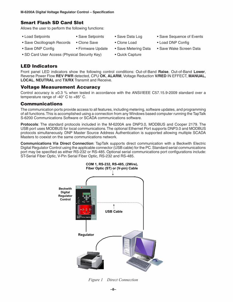
Communications Via Direct Connection: TapTalk supports direct communication with a Beckwith Electric Digital Regulator Control using the applicable connector (USB cable) for the PC. Standard serial communications port may be specified as either RS-232 or RS-485. Optional serial communications port configurations include: ST-Serial Fiber Optic, V-Pin Serial Fiber Optic, RS-232 and RS-485.
COM 1, RS-232, RS-485, (2Wire),Fiber Optic (ST) or (V-pin) Cable
USB Cable
Regulator
Printer Windows® based computer Running TapTalk® Communications Software
Beckwith Digital
RegulatorControl
Figure 1 Direct Connection
–9–
M-6200A Digital Voltage Regulator Control – Specification
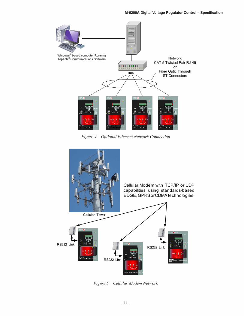
Optional Ethernet Port: The optional Ethernet Port provides a RJ45 (10/100 Base-T) or a Fiber Optic through ST or SC connectors (100 Base-Fx) interface for ethernet communication to the M-6200A. The protocols supported are: MODBUS over TCP/IP, DNP3.0 over TCP/IP and DNP3.0 over UDP. The port supports up to eight concurrent connections. The maximum number of allowed DNP connections is five. The maximum number of MODBUS connections is eight. The port supports DHCP protocol and also allows manual configuration of the Ethernet port. MODBUS protocol "Port Number" and DNP Protocol "Port Number" are required for manual configuration. DNP Master Source Address Authentication is supported allowing multiple SCADA Masters to coexist on the same communications network.
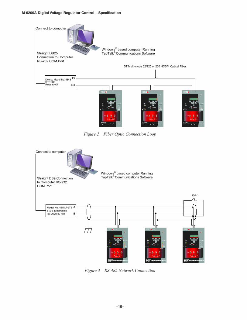
Communications Using Networking: The addressing capability of the M-6200A allows networking of multiple Beckwith Electric Digital Regulator Controls. Each regulator control can be assigned a Communications Address, Feeder Address or Substation Address ranging from 1 to 65519. Selected commands may be broadcast to all controls on the network. Figures 2, 3 and 4 illustrate typical network configurations. Addresses 1 to 247 can be assigned to MODBUS and 1 to 65519 for DNP3.0.
Optional Bluetooth: The optional Bluetooth (V2.0 +EDR Class 1 Type) provides wireless access to the M-6200A. With Bluetooth the user is able to configure the control, read status and metering values as well as change setpoints. This option can be field installed. There are two modes of operation for the Bluetooth:
Mode 0 – The device is discoverable and connectable to any client station.
Mode 1 – The device is non-discoverable but it is connectable to any client station who knows the control Bluetooth device address indicated under “Control BT Device” in the HMI.
Mode 1 – Has been added to meet CIP requirement. (CIP-0007-4 System Security Management) (R2.3)
Cyber SecurityNERC CIP Compliance: The M-6200A provides all the necessary tools to help customers be NERC and Cyber Security compliant. The M-6200A meets or exceeds the following standards:
IEEE 1686-2007 Compliant
FIPS180-2, 186-2
IEC 62351-1, -2, -3, -5
ISO/IEC 9798-4
IPsec using Internet Key Exchange (IKE) Version 1 and 2, compliant with: RFC 2367, 2393, 2394, 2401, 2402, 2406, 2407, 2408, 2409, 2411, 2412, 3456, 3706, 3947 and 3948
RADIUS Server Support (optional), compliant with: RFC 2865 and 2866
BECO Standard Security: The default Level Access Code Security provides authentication and multi level access codes. A Smart Flash SD card may also serve as a cyber security hard-key with a user access audit log.
Application: Using a PC or wireless modem, the operator has real-time, remote access to all functions of the Digital Regulator Control. The control can act as the monitoring point for all voltage, current, and related power quantities, thereby simplifying operation while avoiding transducers and multiple Remote Terminal Unit (RTU) analog inputs. The protocols implement half-duplex, two-way communications. This allows all functions, which would otherwise require the presence of an operator at the control, to be performed remotely. Communication capabilities include:
• Interrogation and modification of setpoints
• Broadcast of commands, such as tapchange inhibit and voltage reduction (up to three steps) to networked controls
• Recognition of alarm conditions, such as voltage extremes and excessive load
• Selective control of raise and lower tapchange operations
• Re-configuration of the control, such as a change to the demand integration time period or a selection of different alarm parameters
• Unsolicited exception reporting multicast capability using UDP
• DNP file transfer of Data Logging, Oscillography and Sequence of Events records
Unit Identifier: A 2-row by 20-character alphanumeric sequence, set by the user, can be used for unit identification.
–10–
M-6200A Digital Voltage Regulator Control – Specification
Dymec Model No. 5843DTE=OnRepeat=Off
TX
RX
ST Multi-mode 62/125 or 200 HCS™ Optical Fiber
Connect to computer
Straight DB25 Connection to Computer RS-232 COM Port
Windows® based computer Running TapTalk® Communications Software
Figure 2 Fiber Optic Connection Loop
A
B
Model No. 485 LP9TBB & B ElectronicsRS-232/RS-485
120
Connect to computer
Straight DB9 Connection to Computer RS-232 COM Port
Windows® based computer Running TapTalk® Communications Software
Figure 3 RS‑485 Network Connection
–11–
M-6200A Digital Voltage Regulator Control – Specification
Network CAT 5 Twisted Pair RJ-45
orFiber Optic Through
ST ConnectorsHub
Windows® based computer Running TapTalk® Communications Software
Figure 4 Optional Ethernet Network Connection
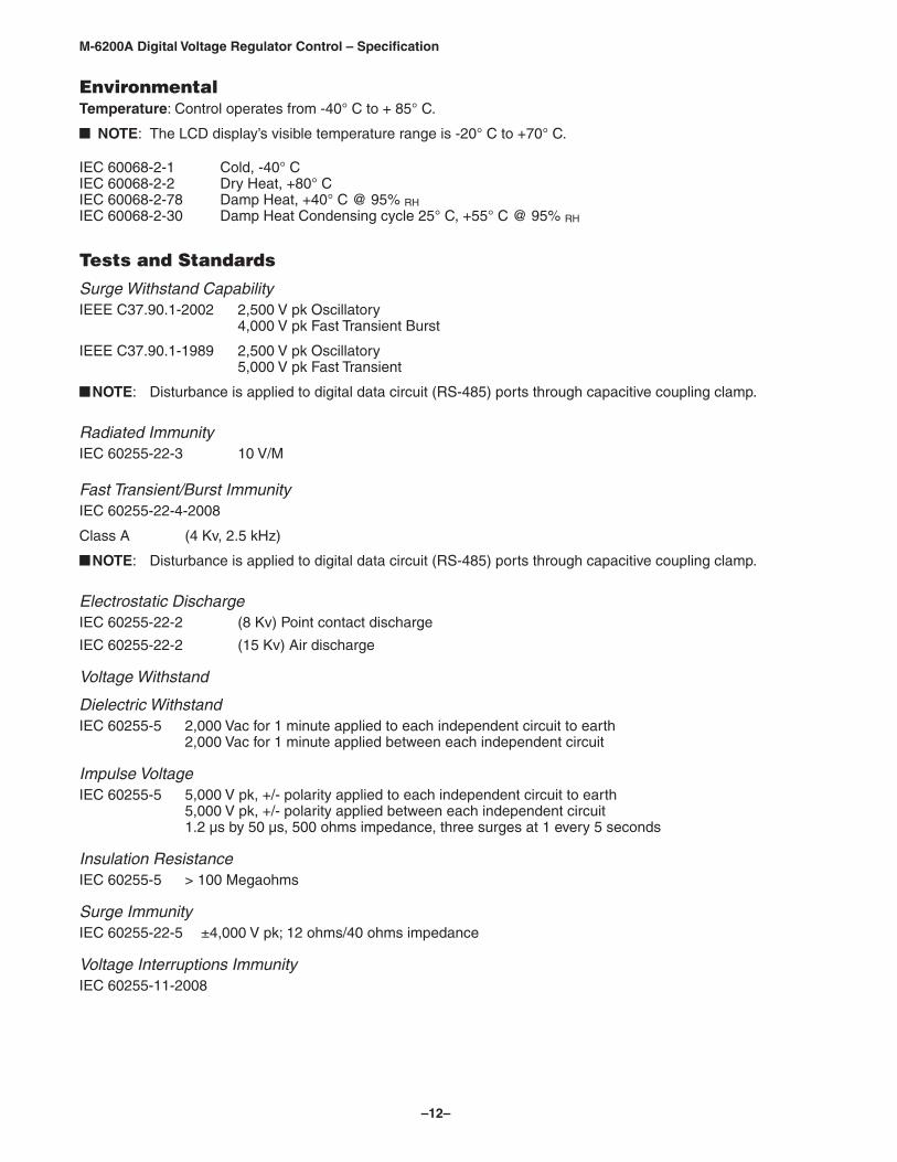
RS232 Link
RS232 LinkRS232 Link
Cellular Tower
Cellular Modem with TCP/IP or UDPcapabilities using standards-basedEDGE, GPRS or CDMA technologies
Figure 5 Cellular Modem Network
–12–
M-6200A Digital Voltage Regulator Control – Specification
EnvironmentalTemperature: Control operates from -40° C to + 85° C.
NOTE: The LCD display’s visible temperature range is -20° C to +70° C.
IEC 60068-2-1 Cold, -40° CIEC 60068-2-2 Dry Heat, +80° CIEC 60068-2-78 Damp Heat, +40° C @ 95% RHIEC 60068-2-30 Damp Heat Condensing cycle 25° C, +55° C @ 95% RH
Tests and Standards
Surge Withstand CapabilityIEEE C37.90.1-2002 2,500 V pk Oscillatory 4,000 V pk Fast Transient Burst
IEEE C37.90.1-1989 2,500 V pk Oscillatory 5,000 V pk Fast Transient
NOTE: Disturbance is applied to digital data circuit (RS-485) ports through capacitive coupling clamp.
Radiated ImmunityIEC 60255-22-3 10 V/M
Fast Transient/Burst ImmunityIEC 60255-22-4-2008
Class A (4 Kv, 2.5 kHz)
NOTE: Disturbance is applied to digital data circuit (RS-485) ports through capacitive coupling clamp.
Electrostatic DischargeIEC 60255-22-2 (8 Kv) Point contact discharge
IEC 60255-22-2 (15 Kv) Air discharge
Voltage Withstand
Dielectric WithstandIEC 60255-5 2,000 Vac for 1 minute applied to each independent circuit to earth 2,000 Vac for 1 minute applied between each independent circuit
Impulse VoltageIEC 60255-5 5,000 V pk, +/- polarity applied to each independent circuit to earth 5,000 V pk, +/- polarity applied between each independent circuit 1.2 µs by 50 µs, 500 ohms impedance, three surges at 1 every 5 seconds
Insulation ResistanceIEC 60255-5 > 100 Megaohms
Surge ImmunityIEC 60255-22-5 ±4,000 V pk; 12 ohms/40 ohms impedance
Voltage Interruptions ImmunityIEC 60255-11-2008
–13–
M-6200A Digital Voltage Regulator Control – Specification
Mechanical EnvironmentIEC 60255-21-1 Vibration Response Class 1 0.5 g Vibration Endurance Class 1 1 g
IEC 60255-21-2 Shock Response Class 1 5 g Shock Withstand Class 1 15 g Bump Endurance Class 1 10 g
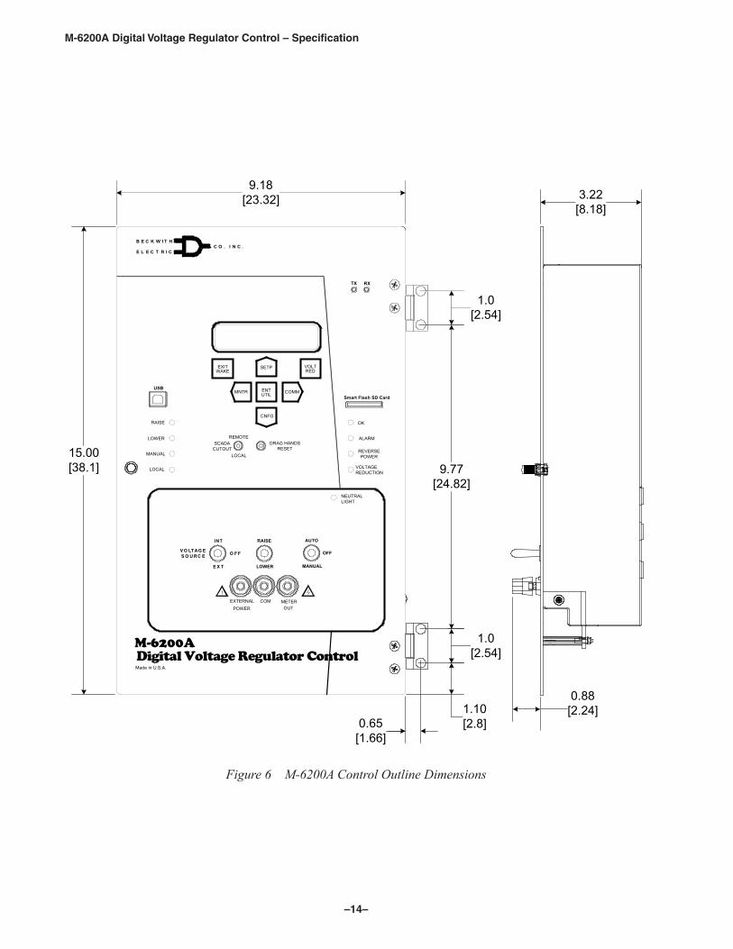
PhysicalSize: 9.25” wide x 15.00” high x 3.25” deep (23.5 cm x 38.1 cm x 8.26 cm)
Mounting: Unit mounts directly into General Electric, Siemens, Howard Industries and Cooper Regulator control cabinets with appropriate installation kits.
Approximate Weight: 6 lbs, 5 oz (2.95 kg)
Approximate Shipping Weight: 10 lbs, 5 oz (4.56 kg)
Recommended Storage ParametersTemperature: 5° C to 40° C.
Humidity: Maximum relative humidity 80% for temperatures up to 31° C, decreasing to 31° C linearly to 50% relative humidity at 40° C.
Environment: Storage area to be free of dust, corrosive gases, flammable materials, dew, percolating water, rain and solar radiation.
M-2026/M-2027 Control Power Backup SuppliesThe M-2026 and M-2027 units are housed in a non-weathertight enclosure and equipped with screw terminal blocks for input and output connections.
Use of a control power backup supply other than the M-2026 and M-2027 will compromise system reliability if the power supplies chosen do not conform to the following specifications.
M-2026 AC-DC Control Power Backup SupplyThe M-2026 Control Power Backup Supply will accept either an AC or DC input over the following ranges:
• 21 to 32 V
• 42 to 60 V
• 105 to 145 V
NOTE: It must be ordered in the input range needed.
The M-2026 will output a regulated +12 Vdc (+0.5 V) output voltage. The unit incorporates a fused input, surge protection, and reverse polarity protection. The M-2026 is capable of up to a 1.5 Ampere output.
M-2027 Control Power Backup Supply-AC OnlyThe M-2027 will accept an AC (105 to 140 Vac, 50/60 Hz) input and output +12 Vdc (Nominal). The M-2027 is capable of loads up to 1.0 Ampere. The unit incorporates a fused input and surge protection.
Patent & WarrantyThe Regulator Controls are covered by U.S. Patents 5,315,527 and 5,581,173.
The Regulator Controls, M-2026 AC-DC Control Power Backup Supply and M-2027 Control Power Backup Supply-AC Only are covered by a ten year warranty from date of shipment.
TrademarksAll brand or product names referenced in this document may be trademarks or registered trademarks of their respective holders.
Specification subject to change without notice. Beckwith Electric Co., Inc. has approved only the English version of this document.
–14–
M-6200A Digital Voltage Regulator Control – Specification
15.00[38.1]
Smart Flash SD Card
S O U RC EV O LTAG E
INT
E X T
O F F
USB
RXTX
9.18[23.32]
0.65[1.66]
1.10[2.8]
1.0[2.54]
9.77[24.82]
1.0[2.54]
3.22[8.18]
0.88[2.24]
OK
LOWER ALARM
EXTERNAL POWER
METEROUT
MANUAL
LOCAL
RAISE
REMOTE
LOCAL
SCADACUTOUT
DRAG HANDSRESET
VOLTAGEREDUCTION
REVERSEPOWER
COM
!
Made in U.S.A.
Digital Voltage Regulator ControlM-6200A
HTIWKCEB
CIRTCELE.CNI.OC
EXITWAKE
VOLTRED
ENTUTIL
SETP
COMMMNTR
CNFG
MANUAL
AUTO
OFF
LOWER
RAISE
NEUTRALLIGHT
Figure 6 M‑6200A Control Outline Dimensions
–15–
M-6200A Digital Voltage Regulator Control – Specification
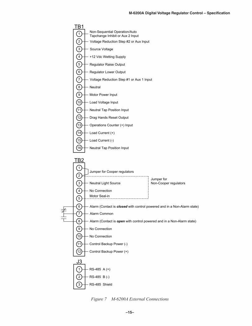
+12 Vdc Wetting Supply
Source Voltage
Load Current (+)
Load Voltage Input
Regulator Raise Output
Motor Power Input
Voltage Reduction Step #2 or Aux Input
Neutral Tap Position Input
Neutral
Regulator Lower Output
Non-Sequential Operation/Auto Tapchange Inhibit or Aux 2 Input
Voltage Reduction Step #1 or Aux 1 Input
1
2
3
4
5
6
7
8
9
10
11
12
TB2
1
2
3
4
5
6
7
8
9
10
11
12
13
14
15
TB1
16
No Connection
Drag Hands Reset Output
Operations Counter (+) Input
Load Current (-)
Neutral Tap Position Input
Jumper for Cooper regulators
Neutral Light Source
Motor Seal-in
Alarm (Contact is closed with control powered and in a Non-Alarm state)
Alarm Common
Alarm (Contact is open with control powered and in a Non-Alarm state)
No Connection
No Connection
Control Backup Power (-)
Control Backup Power (+)
1
2
3
J3RS-485 A (+)
RS-485 B (-)
RS-485 Shield
Jumper for Non-Cooper regulators
Figure 7 M‑6200A External Connections
BECKWITH ELECTRIC CO., INC.6190 - 118th Avenue North • Largo, Florida 33773-3724 U.S.A.
PHONE (727) 544-2326 • FAX (727) [email protected]
www.beckwithelectric.comISO 9001:2015
800-6200A-SP-08 04/18© 2006 Beckwith Electric Co.Printed in U.S.A. (09.24.02)
Recommended