Embed Size (px)
Citation preview
International Journal of Electrical Engineering and Technology (IJEET), ISSN 0976 – 6545(Print),
ISSN 0976 – 6553(Online) Volume 5, Issue 7, July (2014), pp. 20-31 © IAEME
20
EFFECT OF LIGHTNING OVER-VOLTAGES ON THE ELECTRIFIED AC
& DC TRANSMISSION LINE FOR RAILWAY SYSTEM
Prof Avishkar V Wanjari
Electrical Engineering Department, Govindrao Wanjari College of Engineering &
Technology Nagpur, India
ABSTRACT
The distribution system is formed from number of elements which runs continuously in order
to complete the demand of consumers. Transient over voltages in the power distribution system is
the most important factor which should be considered while developing and designing a new system.
Considering the importance of continuation in supply in order to complete the demand, a proper
protection device should be implemented. So with this importance the said project was started.
Under this paper, the effect of lightning on the railway overhead line is seen along with the
other parts and elements which plays important role in order to run this over head lines.
PSCAD/EMTDC software was used to design an Electrified railway system in order to investigate
the consequences of transient over voltages caused due to lightning phenomenon. This paper also
highlights the effective use of surge arrester in order to protect the system from the surges.
I. INTRODUCTION
Dangerous, strong and amazing; lightning is the most known naturally occurring
phenomenon. The satellites record about 3 million flashes around the world in one day [1]. The
lightning phenomenon does not happen only on earth but it also takes place on the neighboring
planet around us. Even it occurs so frequently around us at various places and planets, it is still not
been completely understood.
The work discussed in this report gives the basic idea of the some natural phenomenon
occurring around us and its consequences on the electrical components or devices that are being
used. Lightning is the most common natural phenomenon occurring in the nature during thunder
storms. The direct strike of lightning on any electrical element, sources, etc., which are open under
the clouds may result into the damage of equipment. Therefore, considering its importance in the
electrical field it has been selected for the study. It was seen that a lot of work is done on
understanding the effects of lightning on the transmission lines.
INTERNATIONAL JOURNAL OF ELECTRICAL ENGINEERING &
TECHNOLOGY (IJEET)
ISSN 0976 – 6545(Print) ISSN 0976 – 6553(Online) Volume 5, Issue 7, July (2014), pp. 20-31
© IAEME: www.iaeme.com/IJEET.asp Journal Impact Factor (2014): 6.8310 (Calculated by GISI) www.jifactor.com
IJEET
© I A E M E
International Journal of Electrical Engineering and Technology (IJEET), ISSN 0976 – 6545(Print),
ISSN 0976 – 6553(Online) Volume 5, Issue 7, July (2014), pp. 20-31 © IAEME
21
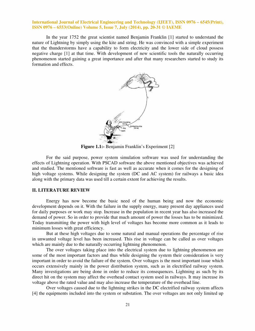
In the year 1752 the great scientist named Benjamin Franklin [1] started to understand the
nature of Lightning by simply using the kite and string. He was convinced with a simple experiment
that the thunderstorms have a capability to form electricity and the lower side of cloud possess
negative charge [1] at that time. With development of new scientific tools the naturally occurring
phenomenon started gaining a great importance and after that many researchers started to study its
formation and effects.
Figure 1.1:- Benjamin Franklin’s Experiment [2]
For the said purpose, power system simulation software was used for understanding the
effects of Lightning operation. With PSCAD software the above mentioned objectives was achieved
and studied. The mentioned software is fast as well as accurate when it comes for the designing of
high voltage systems. While designing the system (DC and AC system) for railways a basic idea
along with the primary data was used till a certain extent for achieving the results.
II. LITERATURE REVIEW
Energy has now become the basic need of the human being and now the economic
development depends on it. With the failure in the supply energy, many present day appliances used
for daily purposes or work may stop. Increase in the population in recent year has also increased the
demand of power. So in order to provide that much amount of power the losses has to be minimized.
Today transmitting the power with high level of voltages has become more common as it leads to
minimum losses with great efficiency.
But at these high voltages due to some natural and manual operations the percentage of rise
in unwanted voltage level has been increased. This rise in voltage can be called as over voltages
which are mainly due to the naturally occurring lightning phenomenon.
The over voltages taking place into the electrical system due to lightning phenomenon are
some of the most important factors and thus while designing the system their consideration is very
important in order to avoid the failure of the system. Over voltages is the most important issue which
occurs extensively mainly in the power distribution system, such as in electrified railway system.
Many investigations are being done in order to reduce its consequences. Lightning as such by its
direct hit on the system may affect the overhead contact system used in railways. It may increase its
voltage above the rated value and may also increase the temperature of the overhead line.
Over voltages caused due to the lightning strikes in the DC electrified railway system affects
[4] the equipments included into the system or substation. The over voltages are not only limited up
International Journal of Electrical Engineering and Technology (IJEET), ISSN 0976 – 6545(Print),
ISSN 0976 – 6553(Online) Volume 5, Issue 7, July (2014), pp. 20-31 © IAEME
22
to lightning or switching but there are some other reasons by which transient over voltages can rise
into the system and may get transferred into the running trains [4]. The other reasons due to which
the over voltage can occur to the DC electrified railway is as follows: -
1. Dc circuit breaker operation which creates over voltage more than 2 times of nominal voltage
[4].
2. Arc formation due to un-even connection of pantograph also results in the formation of over
voltages [4].
3. Operation of vacuum circuit breaker [4].
4. Loose contacts in the electrical equipments [4].
5. Current limiting fuses creates arc which may cause the over voltage [4].
In 2007 at IX International Symposium on Lightning Protection Bernhard Richter [5]
presented the use of surge arrester in the DC railway system. The paper published by him gives the
idea about the installation point and use of surge arresters in dc fed railways.
The same idea about this project was also published in 25th
International System Conference,
2010 [6] by some of the researchers in Iran. The paper includes the same concept which is discussed
above. With the help of ATP software the researchers have shown the use of lightning arrester in the
Light Railway transportation system [6]. The paper shows the results in two cases; including surge
arresters located at various points and without surge arresters. As discussed in the paper, lightning
strike can affect the railway system very badly and for that reason the importance of arresters. So it
was seen that a lot of work was done on the DC feed lines with the help of various softwares.
Though the same thing was not seen for the AC feed lines as they have more chances to get struck by
the lightning due to the long length. As in the developing countries like India where the railways are
reaching each city and town with increased length of lines, it also becomes essential to investigate
the lightning operation effect on such systems.
As discussed in this paper, the power distribution system which is feeding the DC electrified
railways is made of traction substation, overhead lines and feeder cables [4]. From the three phase
source, the power network is converted into DC with the help of rectifier which is then supplied to
moving trains trough the overhead lines. In this paper, the transient over voltages can easily enter the
electrical equipment of the traction station. So in order to protect the system more effectively various
installation points are important to be considered. The installations points are [4] as listed below: -
1) In the traction substation at primary terminal of transformer and rectifier
2) Ac side of the rectifier unit
3) DC side of the rectifier
4) In between the rectifier output and the input to the overhead line of railway
5) Input point coming from overhead lines to the train
International Journal of Electrical Engineering and Technology (IJEET), ISSN 0976 – 6545(Print),
ISSN 0976 – 6553(Online) Volume 5, Issue 7, July (2014), pp. 20-31 © IAEME
23
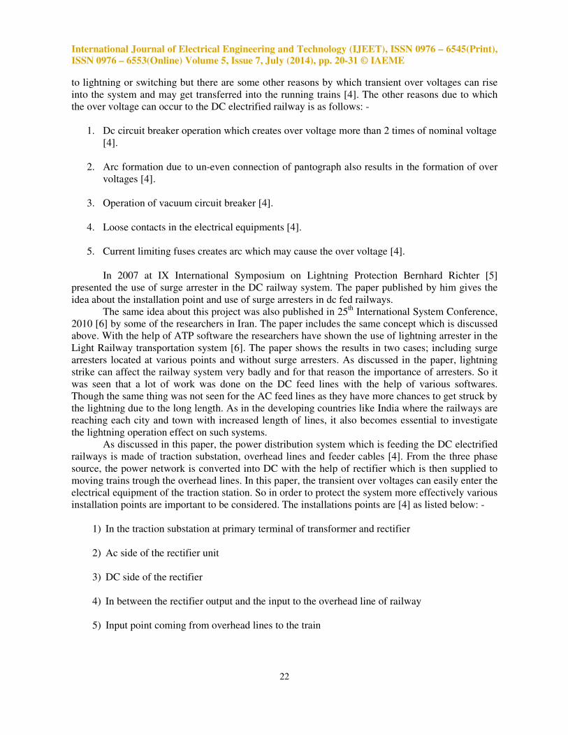
III. DESIGNING AND IMPLEMENTATION IN PSCAD
SOFTWARE
The DC system in this case is the Iranian network which is described in the research paper by
the researchers Mr. Farhad Shahnia and Mr. G. Gharehpetian [4]. For designing this system into the
software, the basic idea in order to achieve the DC as the output is considered which can be seen in
the block diagram below.
Figure 3.1: - Block diagram for DC system
The AC system is now being used in many countries because of its various advantages which
may be technical or non technical. In designing the AC system a simple is considered which can be
seen in the following figure.
Figure 3.2: - Block Diagram for AC supply system
From the above figure it can be said that, each substation has a source of supply which may
be coming from the same location or from some different location for different substations. Also the
substations are equipped with the transformer for the voltage variation which can be supplied to the
overhead lines. Here a single phase supply is given to the overhead line for the further operation.
Now as the train needs a three phase supply to run the motors placed in it, a drive converter is used
to get the three phases from a single phase overhead line.
International Journal of Electrical Engineering and Technology (IJEET), ISSN 0976 – 6545(Print),
ISSN 0976 – 6553(Online) Volume 5, Issue 7, July (2014), pp. 20-31 © IAEME
24
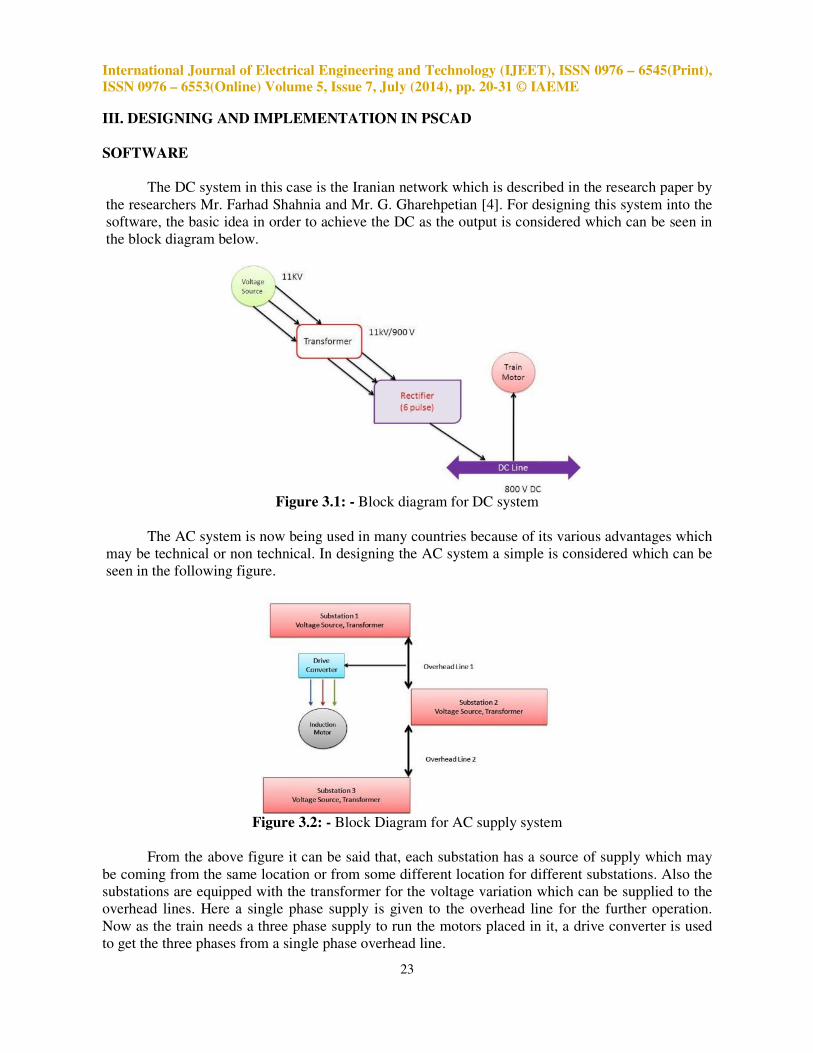
IV. ANALYSIS AND RESULTS
Lightning Condition in AC Line: The complete design that is achieved on PSCAD is shown in the
figure below,
Figure 4.1: - AC system designed in PSCAD software
This lightning was strike between the two substations which can be seen in above figure
When such a high voltage transient travels through the line, the peak voltage of 14.5 KV is observed
along the line which travels in the both direction of the line.
Figure 4.2: - Voltage across substation 1
From the above graph it can be seen that the high peak voltage caused due to lightning travels
along the line and enters the substation. Such a transient voltage can be very dangerous to the
transformer connected in station.
Figure 4.3: - Voltage across substation 2
As the lightning has struck on second substation between two overhead lines here the voltage
same as the lightning voltage can be seen. A high peak of 14 KV appears across the line which falls
after certain time.
International Journal of Electrical Engineering and Technology (IJEET), ISSN 0976 – 6545(Print),
ISSN 0976 – 6553(Online) Volume 5, Issue 7, July (2014), pp. 20-31 © IAEME
25
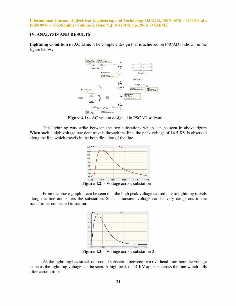
Figure 4.4: - Voltage across substation 3
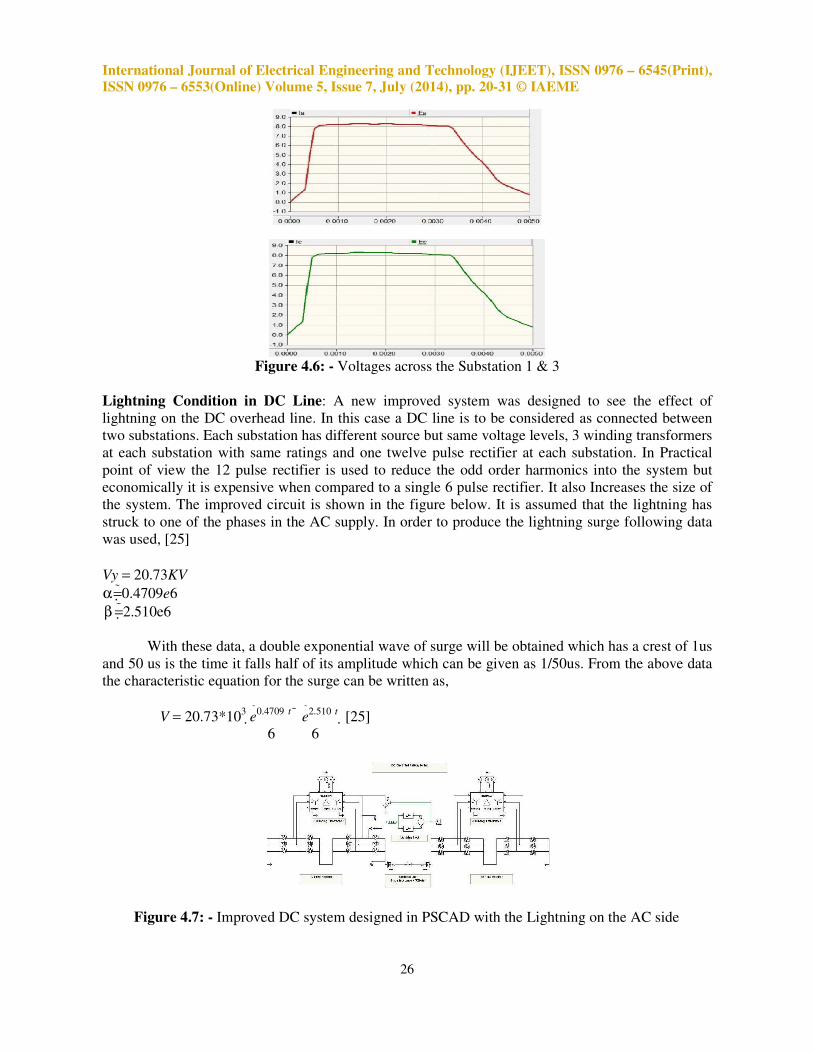
As seen from above graph the high peak voltage due to lightning also affects the substation 3.
Such transient voltages can be harmful for the equipments used in the substation thus protecting
them from such situation is very essential in order to minimize the economical losses.
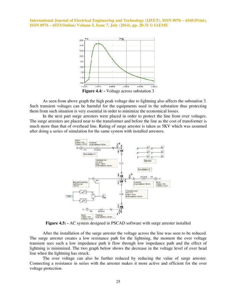
In the next part surge arresters were placed in order to protect the line from over voltages.
The surge arresters are placed near to the transformer and before the line as the cost of transformer is
much more than that of overhead line. Rating of surge arrester is taken as 5KV which was assumed
after doing a series of simulation for the same system with installed arresters.
Figure 4.5: - AC system designed in PSCAD software with surge arrester installed
After the installation of the surge arrester the voltage across the line was seen to be reduced.
The surge arrester creates a low resistance path for the lightning, the moment the over voltage
transient sees such a low impedance path it flow through low impedance path and the effect of
lightning is minimized. The two graph below shows the decrease in the voltage level of over head
line when the lightning has struck.
The over voltage can also be further reduced by reducing the value of surge arrester.
Connecting a resistance in series with the arrester makes it more active and efficient for the over
voltage protection.
International Journal of Electrical Engineering and Technology (IJEET), ISSN 0976 – 6545(Print),
ISSN 0976 – 6553(Online) Volume 5, Issue 7, July (2014), pp. 20-31 © IAEME
26
Figure 4.6: - Voltages across the Substation 1 & 3
Lightning Condition in DC Line: A new improved system was designed to see the effect of
lightning on the DC overhead line. In this case a DC line is to be considered as connected between
two substations. Each substation has different source but same voltage levels, 3 winding transformers
at each substation with same ratings and one twelve pulse rectifier at each substation. In Practical
point of view the 12 pulse rectifier is used to reduce the odd order harmonics into the system but
economically it is expensive when compared to a single 6 pulse rectifier. It also Increases the size of
the system. The improved circuit is shown in the figure below. It is assumed that the lightning has
struck to one of the phases in the AC supply. In order to produce the lightning surge following data
was used, [25]
Vy = 20.73KV
α = 0.4709e6
β = 2.510e6
With these data, a double exponential wave of surge will be obtained which has a crest of 1us
and 50 us is the time it falls half of its amplitude which can be given as 1/50us. From the above data
the characteristic equation for the surge can be written as,
V = 20.73*103 e 0.4709
t e 2.510
t [25]
6 6
Figure 4.7: - Improved DC system designed in PSCAD with the Lightning on the AC side
International Journal of Electrical Engineering and Technology (IJEET), ISSN 0976 – 6545(Print),
ISSN 0976 – 6553(Online) Volume 5, Issue 7, July (2014), pp. 20-31 © IAEME
27
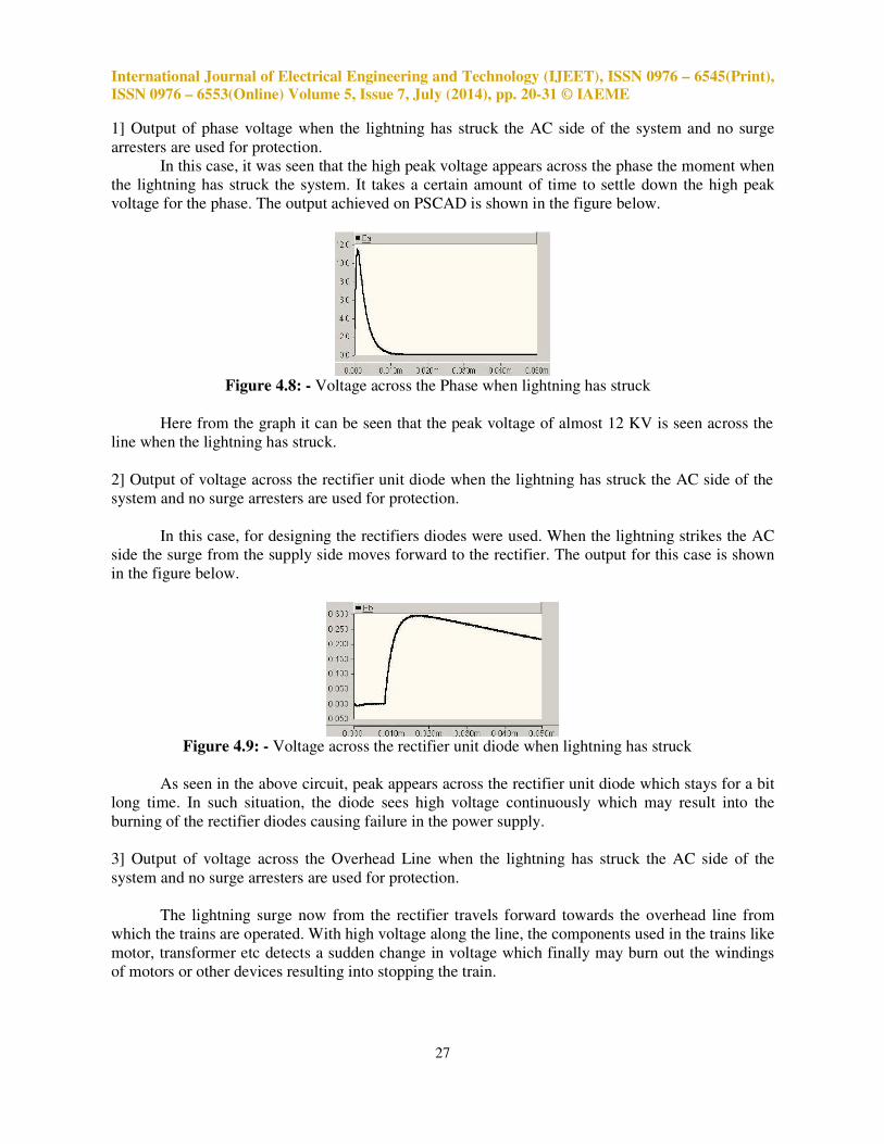
1] Output of phase voltage when the lightning has struck the AC side of the system and no surge
arresters are used for protection.
In this case, it was seen that the high peak voltage appears across the phase the moment when
the lightning has struck the system. It takes a certain amount of time to settle down the high peak
voltage for the phase. The output achieved on PSCAD is shown in the figure below.
Figure 4.8: - Voltage across the Phase when lightning has struck
Here from the graph it can be seen that the peak voltage of almost 12 KV is seen across the
line when the lightning has struck.
2] Output of voltage across the rectifier unit diode when the lightning has struck the AC side of the
system and no surge arresters are used for protection.
In this case, for designing the rectifiers diodes were used. When the lightning strikes the AC
side the surge from the supply side moves forward to the rectifier. The output for this case is shown
in the figure below.
Figure 4.9: - Voltage across the rectifier unit diode when lightning has struck
As seen in the above circuit, peak appears across the rectifier unit diode which stays for a bit
long time. In such situation, the diode sees high voltage continuously which may result into the
burning of the rectifier diodes causing failure in the power supply.
3] Output of voltage across the Overhead Line when the lightning has struck the AC side of the
system and no surge arresters are used for protection.
The lightning surge now from the rectifier travels forward towards the overhead line from
which the trains are operated. With high voltage along the line, the components used in the trains like
motor, transformer etc detects a sudden change in voltage which finally may burn out the windings
of motors or other devices resulting into stopping the train.

International Journal of Electrical Engineering and Technology (IJEET), ISSN 0976 – 6545(Print),
ISSN 0976 – 6553(Online) Volume 5, Issue 7, July (2014), pp. 20-31 © IAEME
28
Figure 4.10: - Voltage across the DC overhead Line
The above graph shows the high peak voltage surge across the DC overhead line when the
lightning has struck the system.
So, in the above part it was seen that lightning strike can severely cause damage to the system
components used which are very expensive. So in order to protect the components used in the system
surge arresters are installed which can also be seen in the following figure.
Figure 4.11: - Improved DC system designed in PSCAD with surge arrester installed
4] Output of voltage across the rectifier unit diode when the lightning has struck the AC side of the
system and surge arresters are used for protection.
Now for protecting the device from over voltages transient, the surge arrester was installed.
The surge arrester reduces the high transient voltage that occurs during the lightning. The output for
the rectifier diode is shown below which proves that the surge arrester are protecting the diodes.
Figure 4.12: - Voltage across rectifier unit diode when surge arresters are installed
From the graph it can be seen that initially a negative wave is seen, which can be due to the
diodes or the difference in the impedance levels.
5] Output of voltage across the Overhead line when the lightning has struck the AC side of the
system and surge arresters are used for protection.
International Journal of Electrical Engineering and Technology (IJEET), ISSN 0976 – 6545(Print),
ISSN 0976 – 6553(Online) Volume 5, Issue 7, July (2014), pp. 20-31 © IAEME
29
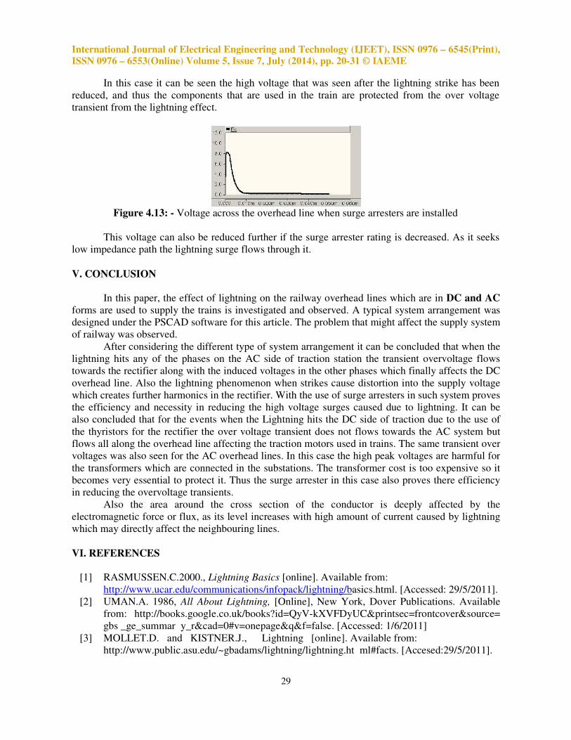
In this case it can be seen the high voltage that was seen after the lightning strike has been
reduced, and thus the components that are used in the train are protected from the over voltage
transient from the lightning effect.
Figure 4.13: - Voltage across the overhead line when surge arresters are installed
This voltage can also be reduced further if the surge arrester rating is decreased. As it seeks
low impedance path the lightning surge flows through it.
V. CONCLUSION
In this paper, the effect of lightning on the railway overhead lines which are in DC and AC
forms are used to supply the trains is investigated and observed. A typical system arrangement was
designed under the PSCAD software for this article. The problem that might affect the supply system
of railway was observed.
After considering the different type of system arrangement it can be concluded that when the
lightning hits any of the phases on the AC side of traction station the transient overvoltage flows
towards the rectifier along with the induced voltages in the other phases which finally affects the DC
overhead line. Also the lightning phenomenon when strikes cause distortion into the supply voltage
which creates further harmonics in the rectifier. With the use of surge arresters in such system proves
the efficiency and necessity in reducing the high voltage surges caused due to lightning. It can be
also concluded that for the events when the Lightning hits the DC side of traction due to the use of
the thyristors for the rectifier the over voltage transient does not flows towards the AC system but
flows all along the overhead line affecting the traction motors used in trains. The same transient over
voltages was also seen for the AC overhead lines. In this case the high peak voltages are harmful for
the transformers which are connected in the substations. The transformer cost is too expensive so it
becomes very essential to protect it. Thus the surge arrester in this case also proves there efficiency
in reducing the overvoltage transients.
Also the area around the cross section of the conductor is deeply affected by the
electromagnetic force or flux, as its level increases with high amount of current caused by lightning
which may directly affect the neighbouring lines.
VI. REFERENCES
[1] RASMUSSEN.C.2000., Lightning Basics [online]. Available from:
http://www.ucar.edu/communications/infopack/lightning/basics.html. [Accessed: 29/5/2011].
[2] UMAN.A. 1986, All About Lightning, [Online], New York, Dover Publications. Available
from: http://books.google.co.uk/books?id=QyV-kXVFDyUC&printsec=frontcover&source=
gbs _ge_summar y_r&cad=0#v=onepage&q&f=false. [Accessed: 1/6/2011]
[3] MOLLET.D. and KISTNER.J., Lightning [online]. Available from:
http://www.public.asu.edu/~gbadams/lightning/lightning.ht ml#facts. [Accesed:29/5/2011].
International Journal of Electrical Engineering and Technology (IJEET), ISSN 0976 – 6545(Print),
ISSN 0976 – 6553(Online) Volume 5, Issue 7, July (2014), pp. 20-31 © IAEME
30
[4] GHAREHPETIAN.G.B., SHAHNIA.F., Lightning and switching transient over voltages in
power Distribution systems feeding DC electrified Railways, Amirkabir University of
Technology, Iran.
[5] RICHTER.B. 2007, Testing of surge arrester for application in lightning endangered areas,
IX International Symposium on Lightning Protection, Brazil.
[6] NIAZY.E., SADEH.J., NIAZY.I. and VESALI.S. (2010),
The Analysis of Lightning on Urban Railway Fed with Direct Current overhead power
supply, 25th
International Power System Conference, Iran.
[7] RAKOV.V. and UMAN.M 2005., Lightning Physics and Effects [Online]. Available from
:http://books.google.com/books?id=TuMa5lAa3RAC&print
sec=frontcover&source=gbs_ge_summary_r&cad=0#v=onepage&q&f=false.[Accessed:30/5/
2011].
[8] MANGOLD.V. 1996, LIFE and LIGHTNING: \The good things of Lightning [Online].
Available from: http://books.google.com/books?id=zwwLaUM4lGAC&printsec=frontcover
&source =gbs _ ge_summary_r&cad=0#v=one page&q&f=false. [Accessed : 30/5/2011].
[9] RAM.B. and VISHWAKARMA.D.N. (2008), Power System Protection and Switchgear,
New Delhi: Tata McGraw-Hill Publishing Company.
[10] ARJUN, Rod Gap Arrester [Online]. Available from:
http://electricalandelectronics.org/2009/03/21/rod-gap- arrester/ [Accessed: 4/6/2011].
[11] GISH.E. (2011), Hewletts with V-S Arching Horns [Online]. Available Rrom:
http://www.r- infinity.com/Hewlett/Page5.htm [Accessed: 4/6/2011].
[12] HERNANDEZ.J., Lightning Arresters: A guide to selection and Application, General
Electric.
[13] STEINFELD.K. and GOHLER.R. 2002, Metal Oxide Surge Arresters for Electric Railways,
Berlin.
[14] RICHTER.B. 2001, Dimensioning, testing and application of metal oxide surge arresters in
low voltage power distribution systems, ABB High Voltage Technologies Ltd, Switzerland.
[15] Train History, web link: http://paralumun.com/train.htm [Accessed: 5/6/2011].
[16] SMITH.M. 2003, Outline History of British Railway System [Online]. Available From:
http://myweb.tiscali.co.uk/gansg/1-hist/01hist.htm.[Accessed: 6/6/2011] .
[17] Online Web Link: www.iloveindia.com/Indian-railways/history.html, [Accessed: 10/6/2011].
[18] Online Web Link: www.thisismyindia.com/Indian- railway/railway-history.html [Accessed:
10/6/2011].
[19] IRFCA 2010, Electric Traction-1, [Online]. Available From: http://www.irfca.org/faq/faq-
elec.html.[ Accessed: 11/6/2011].
[20] Railway Technical Web Pages, Electric Traction Power Supplies, [Online], Available From:
http://www.railway- technical.com/etracp.shtml. [Accessed: 11/6/2011].
[21] ELECTROTEK.INC 2001, PSCAD [online]. Available From:
www.pqsoft.com/pscad/index.htm [Accessed: 13/6/2011].
[22] MANITOBA HVDC RESEARCH CENTRE INC 2007, PSCAD: Visualize, design, simulate,
verify, solve [Online]. Available From:
https://pscad.com/resource/File/Library/PSCAD_Brochure.p df [Accessed: 13/6/2011].
[23] Specification for an 11KV Distribution Transformer, L-S10, May 1990.
[24] PROF. MOOFIK.A (2011), Advance Power System Analysis CE00427 [Lecture Notes],
Staffordshire University, Stafford, UK.
[25] DELFINO.F., PROCOPIO.R. and ROSSI.M 2003, Over voltage Protection of Light Railway
Transportation Systems, IEEE Bologna Power Tech Conference, Italy.
International Journal of Electrical Engineering and Technology (IJEET), ISSN 0976 – 6545(Print),
ISSN 0976 – 6553(Online) Volume 5, Issue 7, July (2014), pp. 20-31 © IAEME
31
ABOUT AUTHOR
Mr Avishkar Wanjari completed his Graduation from Rashtrasanth Tukodoji
Maharaj Nagpur University in the Year 2009. He later completed his Masters
in Electrical Engineering from Staffordshire University, United Kingdom, in
the year 2011. He is now currently working at Govindrao Wanjari College of
Engineering & Technology, Nagpur as an Assistant Professor.


![ROI in the age of keyword not provided [Mozinar]](https://img.pdfslide.net/doc/110x75/53eabc7a8d7f7289708b51f7/roi-in-the-age-of-keyword-not-provided-mozinar.jpg)