Embed Size (px)
Citation preview
B.Vijayalakshmi et al Int. Journal of Engineering Research and Applications www.ijera.com
ISSN : 2248-9622, Vol. 4, Issue 4( Version 4), April 2014, pp.135-146
www.ijera.com 135 | P a g e
Microcontroller Protocol for Secure Broadcast in Controller Area
Networks
B.Vijayalakshmi1, K. Kumar
2
2Assistant Professor, MCA Department, Vel Tech University, Avadi, Chennai – 600 062, Tamil Nadu, India.
1Final Year, Dept. of MCA, Vel Tech University, Avadi, Chennai – 600 062, Tamil Nadu, India.
ABSTRACT Controller Area Network is a bus commonly used by controllers inside vehicles and in various industrial control
applications. In the past controllers were assumed to operate in secure perimeters, but today these environments
are well connected to the outside world and recent incidents showed them extremely vulnerable to cyber-attacks.
To withstand such threats, one can implement security in the application layer of CAN. Here we design, refine
and implement a broadcast authentication protocol based on the well known paradigm of using key-chains and
time synchronization, a commonly used Mechanism in wireless sensor networks, which allows us to take
advantage from the use of symmetric primitives without the need of secret shared keys during broadcast. But, as
process control is a time critical operation we make several refinements in order to improve on the
authentication delay. For this we study several trade-offs to alleviate shortcomings on computational speed,
memory and bandwidth up to the point of using reduced versions of hash functions that can assure ad hoc
security. To prove the efficiency of the protocol
I. INTRODUCTION Modern automotive electronics systems are
dis-tributed as they are implemented with software
run-ning over networked Electronic Control Units
(ECU) communicating via serial buses and gateways.
Most systems (but not all; indeed, the automotive
indus-try has started to take actions to prevent
tampering with calibration parameters in engine
control applica-tions) have not been designed with
security in mind. In addition, in the majority of the
cases, there was little or no interest for hackers to
compromise them. The only exception known so far
is the after-market community that tampers with
engine calibrations to increase engine’s performance.
Methods and tools for the verification of the
reliability of automotive electronics systems against
random failures are commercially available.
However, no security aspect is included as part of the
hardware and software architecture development
process and no standard communication protocol has
any built-in provisions to prevent or mitigate attacks.
Communication networks are vulnerable as they en-
able unauthorized access in a relatively straight for-
ward manner as all the communications between the
ECUs in the vehicle are performed with no authen-
tication [2]. Authentication mechanisms ensure that
sender and receiver identities are not compromised
and thus, the sender and the receiver are who they are
claiming to be. Unfortunately, current communi-
cation network protocols, including Controller Area
Network (CAN), FlexRay, MOST, and LIN have no
authentication (or at best have CRC mechanisms to
the potential exists for an automotive ECU to be infil-
trated by an attacker, who can then potentially gain
access, via a serial communication bus, to an array of
other ECUs. guarantee data integrity) and send their
messages in the clear. Hence, room for fraudulent
communi-cations between ECUs exists. For example,
in the CAN protocol, masquerade attacks followed by
re-play attacks
ECU pretending to be another ECU by
sending/replaying a message the ECU is not en-titled
to send) are likely to happen as messages ex-changed
in a CAN network are broadcast from one ECU to the
rest of the ECUs in the network. In fact, the receiver
cannot verify the identity of the sender of the
message as an attacker could have pretended to be
someone else (and therefore sending a message with
an ID the pretender was not configured to send in the
first place). Again, this scenario is called a
masquerade-based attack which then leads to a pos-
sible ―replay‖ attack as the attacker, by pretending to
The state of the art processes, methods, and
tools We are convinced that security can be taken
into ac-count in the early phases of the development
cycle of automotive electronics systems, both by
enforcing software programming standards that
prevent soft-ware defects that may enable cyber-
attacks, as well as by implementing security
mechanisms such as au-thentication that enable the
validation of the identity of the sender to avoid
potentially harmful messages to be
replayed/transmitted across the communica-tion
network. However, even for known vulnerabil-ities,
one has to perform a cost versus benefits anal-ysis as
RESEARCH ARTICLE OPEN ACCESS
B.Vijayalakshmi et al Int. Journal of Engineering Research and Applications www.ijera.com
ISSN : 2248-9622, Vol. 4, Issue 4( Version 4), April 2014, pp.135-146
www.ijera.com 136 | P a g e
the communication data rates available are very
limited—it is necessary to evaluate whether a full
authentication-based solution that addresses se-curity
concerns is compatible with performance and
resource cost constraints that are typical of automo-
tive embedded systems and specifically of the pre-
dominant communication protocols used in the vehi-
cle (e.g., CAN has very limited data rates between
33kbps and 500kbps). In fact, authentication mech-
anisms typically require large amounts of processing
power, memory, and bandwidth, in addition to those
already reserved for the messages that are exchanged
across ECUs. As more bytes need to be transmitted,
current bus technologies may not be sufficient given
their already limited available bandwidth.
Authentication mechanisms have been
proposed in the literature. The TESLA protocol [3–5]
uses a time-delayed release of keys for
authentication. A receiver can check the Message
Authentication Code (MAC) after receiving the key
used to compute the MAC. To guarantee security, the
protocol needs to maintain global time and make sure
that a receiver gets a message before the
corresponding key is re-leased. In [6–8], the authors
emphasize the con-straints in an embedded network
and consider a time-triggered (i.e., global time is
available) broadcast pro-tocol. Even with the features
proposed for reduc-ing the number of bits transmitted
and for achieving fault tolerance, two major
challenges exist in apply-ing these approaches to the
CAN protocol. First, the bandwidth available in the
CAN protocol is very lim-ited. Second, there is no
notion of global time in the protocol. The challenge
for OEMs in the automotive industry is to design a
security mechanism for CAN with high security,
combined with minimal communi-cation overhead,
high fault tolerance, low cost, and no global
synchronization clock.
In this paper, we describe a security
mechanism that addresses the requirements stated
earlier. Specifi-cally, our mechanism can be used to
retro-fit the CAN protocol to protect it from cyber-
attacks such as masquerade and replay attack with as
low as pos-sible overhead, and high degree of
tolerance to faults.
We address the low cost requirement by
providing a software-only solution with no additional
hardware required. We focus on the CAN protocol
because it is the most used serial data protocol in
current in-vehicle networked architectures, and it will
likely be used for a long time. We define the attack
scenarios that our security mechanism addresses,
namely mas-querade and replay. We focus on a
security mecha-nism based upon message
authentication and sym-metric secret keys. Our
mechanism leverages and modifies the work
described in [6–8] as we introduce the concept of
counters to implement time-stamping of the message
signatures (MACs) in order to over-come the lack of
global time in the CAN protocol. We do not focus on
the initial security critical key assign-ment and
distribution as this aspect, although very important, is
already being mentioned in [6]. Instead, we focus on
run-time authentication both in the sys-tem steady
state (after ignition key-on and the secu-rity secret
keys have been distributed to the ECUs) and during
running resets experienced by some of the ECUs in
the system (when counters are potentially out of
synchronization). Regarding resets, we dis-tinguish
between ECU running resets or any other ECU
expected low-power modes that occur at rates that do
not allow storing in non-volatile memory (flash) the
most recent sending and receiving coun-ters (needed
for authentication) as this would lead to the flash
being non-operational (e.g., due to burn-ing). We
introduce two mechanisms that cope with these
scenarios, which involve either an ECU that heals
itself or a more drastic system-wide counter re-set (or
re-synchronization). We provide an analysis of the
trade-offs and the benefits versus drawbacks of both
approaches. We also consider potential net-work
faults that could hinder the effectiveness of our
security mechanism—we provide a security mecha-
nism that is fault tolerant. Finally, as we are con-
strained by data rates and by costs, we have defined a
software-only mechanism that does not require ad-
ditional hardware. As security has a cost in terms of
performance (because of the additional bits needed
for signatures and counters) and in terms of poten-tial
hazards that may occur due to poor performance, we
also work on exploring trade-offs between degree of
security and other metrics such as resource uti-
lization. Experimental results show that our security
mechanism can achieve high security level without
in-troducing high communication overhead in terms
of bus load and message latency.
The paper is organized as follows: Section II
defines the system and attacker model; Section III
presents the existing mechanisms, their limitations,
our pro-posed security mechanism, and an evaluation
of the impacts of the security mechanism on the
system bus load and the message latency; Section IV
shows the experimental results, and Section V
concludes this paper.
II. SYSTEM AND ATTACKER
MODEL We adapt the terminology from [9] to the automo-
tive use case, where a node is one of the computers
(ECUs) connected to the other ECUs in the vehicle
via a serial data communication bus to provide the
following definitions of attack scenarios:
• Modi cation: an unauthorized node changes
B.Vijayalakshmi et al Int. Journal of Engineering Research and Applications www.ijera.com
ISSN : 2248-9622, Vol. 4, Issue 4( Version 4), April 2014, pp.135-146
www.ijera.com 137 | P a g e
existing data (e.g., a sender node modifies the
data portion of a communication frame to be
transmitted).
• Fabrication: an unauthorized node generates
additional data (e.g, a sender node creates a new
frame with an ID that the node is not au-thorized
to transmit).
• Interception: an unauthorized node reads data
(e.g., a receiver node accepts a message with an
ID that is not supposed to accept and reads the
data portion of the frame).
• Interruption: data becomes unavailable (e.g., a
sender node sends high priority frames over the
communication bus at a very high rate making it
impossible for other frames to be transmit-ted).
For the sake of our discussion, we generalize
modi-cation and fabrication as an unauthorized write
of data by a node, an interception attack as an unau-
thorized read by a node, and an interruption attack as
a Denial-of-Service (DoS) attack. We now define the
following properties:
• Data integrity: data is not changed (written) or
generated by an unauthorized node.
• Con dentiality: data is not read by an unau-
thorized node.
• Authentication: a receiver or a sender is who it
claims to be.
• Non-repudiation: a sender ensures that a re-
ceiver has received the message, and a receiver is
sure about the identity of a sender.
For automotive electronics systems and the
CAN pro-tocol, data integrity and authentication are
very rel-evant properties which are suitable to our
software-only security mechanism solution. To
prevent an in-terruption attack, hardware protections
are required as, because of the very same nature of
the CAN proto-col (broadcast and multi-master with
arbitration), a malicious node can freely read and
write data from/to the bus. Interruption attacks are
outside of the scope of our work.
Before introducing our attacker model, we
first state our assumptions, and provide definitions
about our system model as follows:
Assumption 1. The network architecture has only one
CAN bus, and all ECUs are connected to the bus
itself.
De nition 1. A node is an ECU.
De nition 2. The sender of a message is the node
sending the message.
Assumption 2. A sender sends a message by
broadcasting it on the CAN bus.
De nition 3. A receiver of a message is a node
receiving the message and accepting it by comparing
the message ID to the list of its acceptable message
ID's2.
Note that CAN is a broadcast protocol, so every node
―receives‖ the message, but only receivers (as we
have defined them) accept the message.
Assumption 3. A node can use volatile (RAM) and/or
non-volatile (FLASH) memory to store data. Data
stored in RAM is no longer available after a node
reset; data in FLASH is available after a node resets.
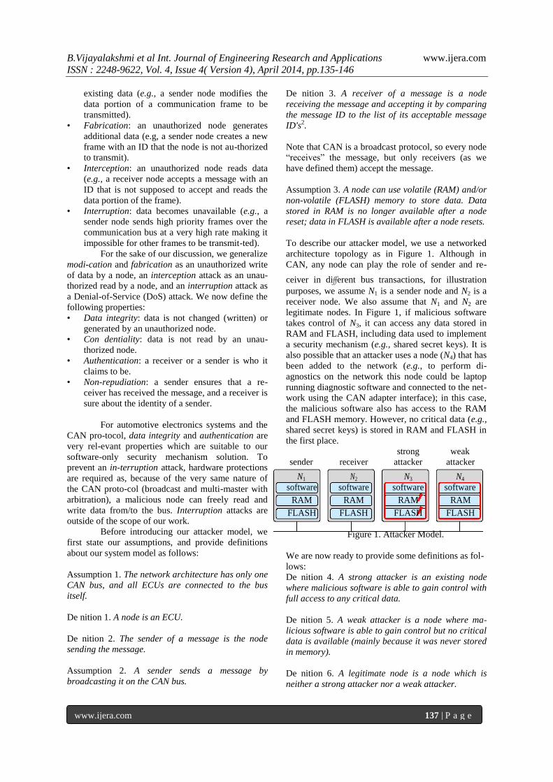
To describe our attacker model, we use a networked
architecture topology as in Figure 1. Although in
CAN, any node can play the role of sender and re-
ceiver in different bus transactions, for illustration
purposes, we assume N1 is a sender node and N2 is a
receiver node. We also assume that N1 and N2 are
legitimate nodes. In Figure 1, if malicious software
takes control of N3, it can access any data stored in
RAM and FLASH, including data used to implement
a security mechanism (e.g., shared secret keys). It is
also possible that an attacker uses a node (N4) that has
been added to the network (e.g., to perform di-
agnostics on the network this node could be laptop
running diagnostic software and connected to the net-
work using the CAN adapter interface); in this case,
the malicious software also has access to the RAM
and FLASH memory. However, no critical data (e.g.,
shared secret keys) is stored in RAM and FLASH in
the first place.
strong weak
sender receiver attacker attacker
N1 N2 N3 N4
software software software software
RAM RAM RAM RAM
FLASH FLASH FLASH FLASH
Figure 1. Attacker Model.
We are now ready to provide some definitions as fol-
lows:
De nition 4. A strong attacker is an existing node
where malicious software is able to gain control with
full access to any critical data.
De nition 5. A weak attacker is a node where ma-
licious software is able to gain control but no critical
data is available (mainly because it was never stored
in memory).
De nition 6. A legitimate node is a node which is
neither a strong attacker nor a weak attacker.
B.Vijayalakshmi et al Int. Journal of Engineering Research and Applications www.ijera.com
ISSN : 2248-9622, Vol. 4, Issue 4( Version 4), April 2014, pp.135-146
www.ijera.com 138 | P a g e
For example, in Figure 1, N3 and N4 are strong and
weak attackers, respectively, and N1 and N2 are le-
gitimate nodes. The possible attack scenarios that N3
and N4 can carry out and that we are addressing with
our solution are:
Types Strong Attacker N3 Weak Attacker N4
Modification
or Scenario 1 Scenario 2
Fabrication
Replay Scenario 3 Scenario 4
In the table, we describe the scenario in which a mes-
sage is supposed to be send by a legitimate sender
(N1). However, N3 and N4 try to alter this situation
with either a strong or weak attack. Again, we are not
addressing attacks such as DoS as they would re-
quire additional hardware—our proposed solution is
software-only. We now explain the scenarios as fol-
lows:
• Scenario 1: this is possible if
important/secret data between N1 and N2 has been
stored in RAM or FLASH of N3. For example, if
impor-
tant/secret data is shared and used by every node in
the network3, then N3 can use the data stored in RAM
or FLASH and pretend to be N1 to send a new
message to N2 (fabrication).
• Scenario 2: there is no threat because no
impor-tant/secret data is stored in RAM or FLASH of
N4.
• Scenario 3: this is possible if N3 reads a
message from the CAN bus and then writes the same
message to the CAN bus without any modifi-cation.
Note that, in this case, N3 does not need to get
important/secret data between N1 and N2, e.g., a
secret pair-wise key as in Fig-ure 2, because N2 will
just accept the message thinking it was sent by N1.
• Scenario 4: same as Scenario 3.
We now define a masquerade and replay
attack and show how we can prevent it as follows [7]:
De nition 7. In a masquerade attack, an attacker
(strong or weak) sends a message in which it claims
to be a node other than itself.
Note that a masquerade attack can lead to a fabri-
cation attack, a modification attack, or as a special
case, a replay attack:
De nition 8. A replay attack is enabled by a
mas-querade attack, and the node in order to be
successful, needs rst to pretend to be another node. In
the case of CAN, in a replay attack a node transmits
a copy (replays) of a message it has received from
the CAN bus. The message is not modi ed or altered.
It is merely sent to other nodes by a node that is not
enti-tled to send it. The other nodes have tables that
match the message id to the sender and therefore,
determine the identity of the sender but have no
provision to au-thenticate it.
Since CAN is a broadcast protocol, both a
strong and weak attacker can successfully carry out a
masquer-ade/replay attack if no security mechanism
is put in place, or even if pair-wise keys are used as
the at-tacker would not need them to successfully
carry on the attack. Before introducing some basic
security mechanisms, we also provide a definition of
a false acceptance and a false rejection as follows:
De nition 9. A false acceptance is the scenario that a
node accepts messages which it should reject.
De nition 10. A false rejection is the scenario that a
node rejects messages which it should accept.
By the definition, a successful attack implies
a false acceptance.
III. SECURITY MECHANISMS In this section, we will first introduce some
basic authentication mechanisms and describe the
exist-ing work in this area in more detail. Then, we
will show the challenges in implementing a security
mechanism for CAN and how we can overcome these
difficulties with our proposal. Finally, we will pro-
vide our counter-based implementation, reset mech-
anisms, and some detailed analysis of their perfor-
mance vs. security levels achieved. We now provide
a few additional definitions that we will use in the
rest of the paper.
Notations Explanations
i the ID of a node
j the ID of a node
k the ID of a message
Ni the node with ID i
Mk the message with ID k
n the number of nodes nk the number of receivers of Mk
rk;s the ID of the s-th receiver of Mk
f the function to compute a MAC
T the time Ki;j the shared secret key of Ni and Nj
Ak;s the MAC for the s-th receiver of Mk
A the MAC computed by a receiver Ci;k the counter stored in Ni for Mk
CM
the most significant bits (MSBs) of a
counter
CL
the least significant bits (LSBs) of a
counter
B.Vijayalakshmi et al Int. Journal of Engineering Research and Applications www.ijera.com
ISSN : 2248-9622, Vol. 4, Issue 4( Version 4), April 2014, pp.135-146
www.ijera.com 139 | P a g e
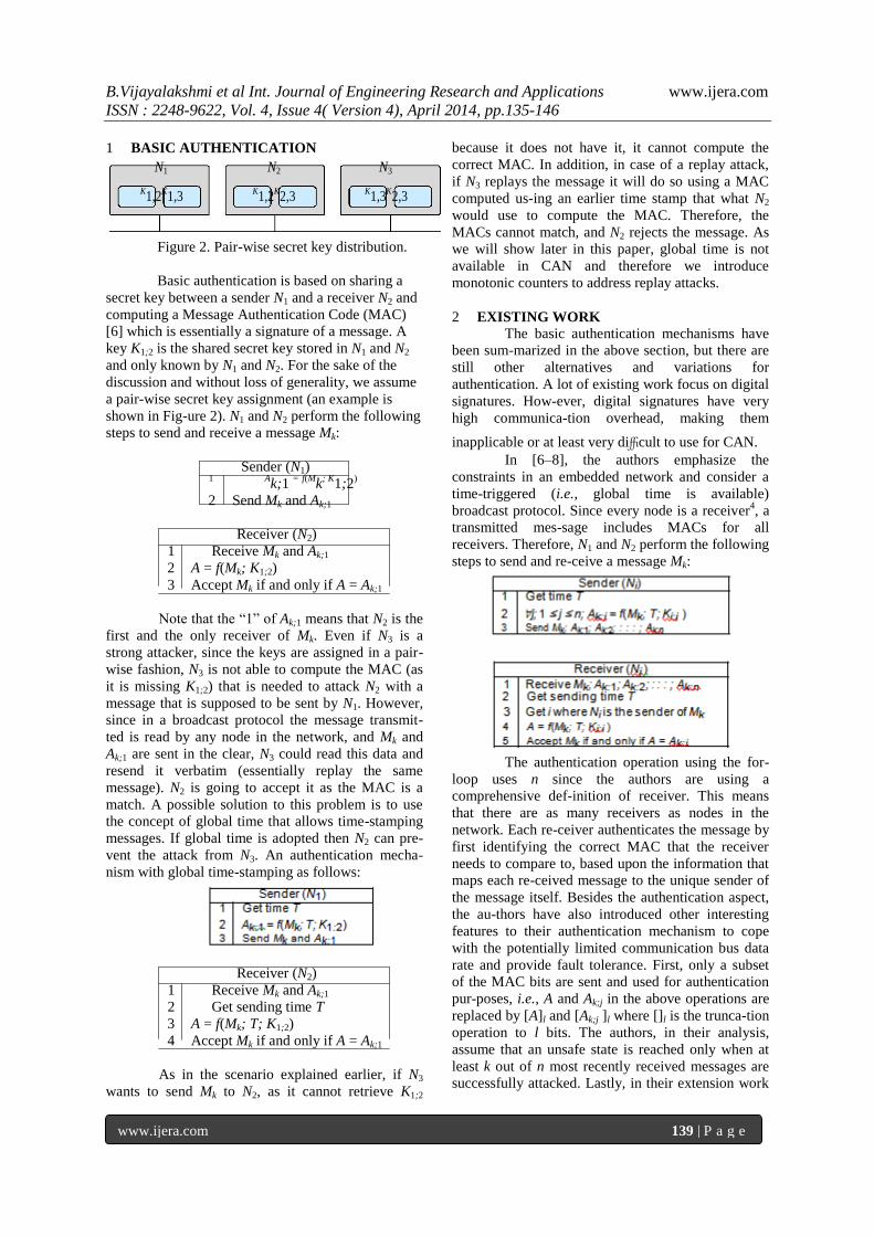
1 BASIC AUTHENTICATION
N1 N2 N3
K1,2
K1,3
K1,2
K2,3
K1,3
K2,3
Figure 2. Pair-wise secret key distribution.
Basic authentication is based on sharing a
secret key between a sender N1 and a receiver N2 and
computing a Message Authentication Code (MAC)
[6] which is essentially a signature of a message. A
key K1;2 is the shared secret key stored in N1 and N2
and only known by N1 and N2. For the sake of the
discussion and without loss of generality, we assume
a pair-wise secret key assignment (an example is
shown in Fig-ure 2). N1 and N2 perform the following
steps to send and receive a message Mk:
Sender (N1) 1
Ak;1
= f(M
k; K
1;2)
2 Send Mk and Ak;1
Receiver (N2)
1 Receive Mk and Ak;1
2 A = f(Mk; K1;2)
3 Accept Mk if and only if A = Ak;1
Note that the ―1‖ of Ak;1 means that N2 is the
first and the only receiver of Mk. Even if N3 is a
strong attacker, since the keys are assigned in a pair-
wise fashion, N3 is not able to compute the MAC (as
it is missing K1;2) that is needed to attack N2 with a
message that is supposed to be sent by N1. However,
since in a broadcast protocol the message transmit-
ted is read by any node in the network, and Mk and
Ak;1 are sent in the clear, N3 could read this data and
resend it verbatim (essentially replay the same
message). N2 is going to accept it as the MAC is a
match. A possible solution to this problem is to use
the concept of global time that allows time-stamping
messages. If global time is adopted then N2 can pre-
vent the attack from N3. An authentication mecha-
nism with global time-stamping as follows:
Receiver (N2)
1 Receive Mk and Ak;1
2 Get sending time T
3 A = f(Mk; T; K1;2)
4 Accept Mk if and only if A = Ak;1
As in the scenario explained earlier, if N3
wants to send Mk to N2, as it cannot retrieve K1;2
because it does not have it, it cannot compute the
correct MAC. In addition, in case of a replay attack,
if N3 replays the message it will do so using a MAC
computed us-ing an earlier time stamp that what N2
would use to compute the MAC. Therefore, the
MACs cannot match, and N2 rejects the message. As
we will show later in this paper, global time is not
available in CAN and therefore we introduce
monotonic counters to address replay attacks.
2 EXISTING WORK
The basic authentication mechanisms have
been sum-marized in the above section, but there are
still other alternatives and variations for
authentication. A lot of existing work focus on digital
signatures. How-ever, digital signatures have very
high communica-tion overhead, making them
inapplicable or at least very difficult to use for CAN.
In [6–8], the authors emphasize the
constraints in an embedded network and consider a
time-triggered (i.e., global time is available)
broadcast protocol. Since every node is a receiver4, a
transmitted mes-sage includes MACs for all
receivers. Therefore, N1 and N2 perform the following
steps to send and re-ceive a message Mk:
The authentication operation using the for-
loop uses n since the authors are using a
comprehensive def-inition of receiver. This means
that there are as many receivers as nodes in the
network. Each re-ceiver authenticates the message by
first identifying the correct MAC that the receiver
needs to compare to, based upon the information that
maps each re-ceived message to the unique sender of
the message itself. Besides the authentication aspect,
the au-thors have also introduced other interesting
features to their authentication mechanism to cope
with the potentially limited communication bus data
rate and provide fault tolerance. First, only a subset
of the MAC bits are sent and used for authentication
pur-poses, i.e., A and Ak;j in the above operations are
replaced by [A]l and [Ak;j ]l where []l is the trunca-tion
operation to l bits. The authors, in their analysis,
assume that an unsafe state is reached only when at
least k out of n most recently received messages are
successfully attacked. Lastly, in their extension work
B.Vijayalakshmi et al Int. Journal of Engineering Research and Applications www.ijera.com
ISSN : 2248-9622, Vol. 4, Issue 4( Version 4), April 2014, pp.135-146
www.ijera.com 140 | P a g e
[8], the authentication is performed by different
voting nodes.
3 CHALLENGES FOR CAN
Even with the features proposed for
reducing the number of bits transmitted and
achieving fault toler-ance, two major challenges exist
in applying the work just described to CAN. First, the
bandwidth available in CAN is extremely limited. In
fact, the maximum and nominal data rate of a CAN
bus is only 500kbps, while each 11-bit ID standard
frame has a maximum total of 134 bits which include
a maximum of 64-bit payload, 46 bits of overhead
(e.g., including CRC bits), and 24 bits for bit-stuffing
[10] in the worst case. If a security mechanism needs
to add MACs to the original frame, as the original
frame might have a 64-bit payload, the frame might
have to be split in two or more frames. This may
result in increasing bus utilization which may result
in a degraded com-munication performance or even
in a unschedulable system. Finally, as stated earlier,
there is no global time in CAN (the global time is
required in [3–8]).
4 OUR SECURITY MECHANISM
The key elements of our proposed security
mecha-nism are stored in each node (in the volatile
and non-volatile memory). The elements are: the ID
table, the pair-wise symmetric secret keys, and
message coun-ters (receiving and sending). In the
following, we use our definition of receivers (see
Definition 3).
• ID table: unlike the approach described in [6– 8],
our mechanism does not use MACs for all nodes.
On the contrary, a sender only computes as many
MACs as the corresponding receivers5 of the
transmitted message. This is done by
maintaining a ID table in each node where each
entry is indexed by a message ID — each entry
contains the node ID of the sender and the list of
the node ID’s of the receivers. We define the ID
table with the following function:
(i; nk; rk;1; rk;2; : : : ; rk;nk ) = ID-Table(k);
where k is the ID of Mk, i is the ID of the sender of
Mk, nk is the number of receivers of Mk, and rk;s is the
ID of the s-th receiver of Mk. A sender can check its
ID table to deter-mine how many MACs it must
compute, what keys it should use, and what ordering
of MACs it should attach with the message. A
receiver can check the ID table to determine what key
it should use and which MAC included in the
received frame it should select. Again, the ad-vantage
of relying on ID tables is that our mech-anism
reduces the number of MACs because it considers
only the receivers that are accept-ing the frame after
CAN filtering, rather than considering the whole set
of receivers that the frame is broadcast to. This can
reduce the com-munication overhead considerably.
• Pair-wise secret key: a pair-wise key Ki;j is
―shared secret‖ between Ni and Nj for authen-
tication. Every pair of nodes has a shared secret
key which is not known by any other node.
Therefore, any other node cannot mod-ify or
fabricate a message, but a replay attack is
possible as explained earlier. Note that using
pair-wise keys is only a basic key distribution
method. If we want to further reduce the com-
munication overhead, we could a assign nodes to
several groups where each node in a group
shares a secret key. Of course, there is a trade-
off between security and performance (minimiz-
ing communication overhead) in that the secu-
rity level is diminished but the communication
performance is improved.
• Message-based counter: a counter is used to re-
place the global time and prevent a replay at-
tack. Each node maintains a set of counters,
and each counter corresponds to a message,
i.e., Ci;k is the counter stored in Ni for Mk. If the
node is the sender of Mk, its counter value
records the number of times that Mk is sent; if
the node is the receiver of Mk, its counter value
records the number of times Mk has been
received (and accepted after being authenti-
cated). Therefore, if a malicious node replays a
message, a receiver can check the correspond-
ing receiving counter to see if a message is
fresh or not. Because of a network fault, a
receiving counter may not have the same value
as that of its sending counter. In other words, it
is possi-ble that a node sends a frame, updates
its send-ing counter, then a network fault
occurs, e.g., the electrical bus has a transient
fault, and thus the frame never reaches its
destination. There-fore, the receiving node
does not receive the frame and thus does not
increase its receiving counter. This means that
two counters are out of synchronization.
However, our mechanism can deal with this
scenario without any loss of security. We will
explain this aspect later in the paper. We now
provide the following additional definitions:
De nition 11. A sending counter for a message is the
counter stored in its sender.
De nition 12. A receiving counter for a message is the
counter stored in one of its receiver.
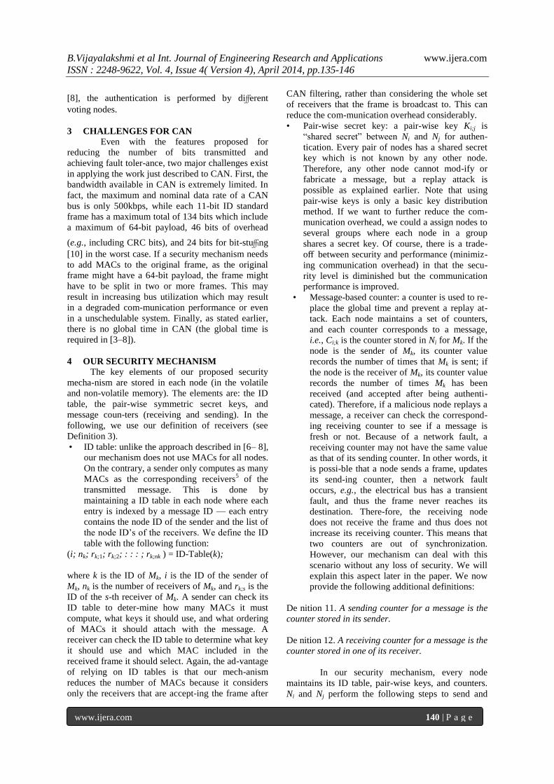
In our security mechanism, every node
maintains its ID table, pair-wise keys, and counters.
Ni and Nj perform the following steps to send and
B.Vijayalakshmi et al Int. Journal of Engineering Research and Applications www.ijera.com
ISSN : 2248-9622, Vol. 4, Issue 4( Version 4), April 2014, pp.135-146
www.ijera.com 141 | P a g e
receive a mes-sage Mk:
Sender (Ni)
1 (i; nk; rk;1; rk;2; : : : ; rk;nk ) = ID-Table(k) 2 C
i;k = Ci;k
+ 1
3 ∀ s;
1 ≤ s ≤ nk
; Ak;s
= f(M
k; C
i;k; K
i;rk;s )
4 Send Mk; Ci;k; Ak;1; Ak;2; : : : ; Ak;nk
Receiver (Nj )
1 Receive Mk; Ci;k; Ak;1; Ak;2; : : : ; Ak;nk
2 (i; nk; rk;1; rk;2; : : : ; rk;nk ) = ID-Table(k)
3
Continue if and only if find s; 1 ≤ s ≤ nk; j =
rk;s
4 Continue if and only if Ci;k > Cj;k
5 A = f(Mk; Ci;k; Ki;j )
6 Accept Mk and Cj;k = Ci;k if and only if A = Ak;s
Based on this mechanism, our security
mechanism can protect any masquerade attack and
replay at-tack. We prove our claim using the
following three scenarios:
• If an attacker sends a message which is not sup-
posed to be received by the receiver, then the
receiver will reject the message in Line 6 by
checking its ID table.
• If an attacker sends a message which is not sup-
posed to be sent by the attacker, and it is a replay
attack, then the receiver will reject the message
in Line 2 by checking the counters.
• If an attacker sends a message which is not sup-
posed to be sent by the attacker, and it is not a
replay attack, then the receiver will reject the
message in Line 12 by comparing the MACs.
5 COUNTER IMPLEMENTATION
These operations can meet the requirements
stated by our problem formulation. However, the
number of bits used for the counter must be explored.
If the number of bits is not sufficient during the life-
time of a vehicle, then the counter may overflow. For
example, if the counter stored at the receiving side
overflows and resets to zero, then the replay attack
may succeed as the attacker just needs to wait for this
event to happen, and therefore resend a counter
which is larger than the reset counter stored in the
receiver; if the number of bits used for the counter is
too large, then the bus will be overloaded. Therefore,
we propose a solution where the counter C is divided
into two parts: the most significant bits (MSBs) CM
and the least significant bits (LSBs) CL—only C
L is
transmitted with the message. The steps performed
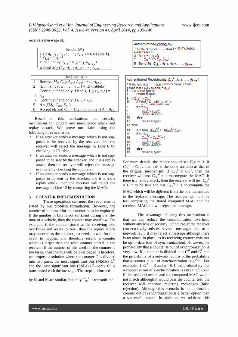
by Ni and Nj are similar, but only Ci;kL is transmit-ted:
For more details, the reader should see Figure 3. If
Ci;kL > Cj;k
L, then this is the same scenario as that of
the original mechanism; if Ci;kL ≤ Cj;k
L, then the
receiver will use Cj;kM
+ 1 to compute the MAC. If
there is a replay attack, then the receiver will test Cj;kL
= C L to be true and use Cj;k
M + 1 to compute the
MAC which will be different from the one transmitted
in the replayed message. The receiver will fail the
test comparing the stored computed MAC and the
received MAC and will reject the message.
The advantage of using this mechanism is
that we can reduce the communication overhead
without any loss of security. Of course, if the receiver
consecu-tively misses several messages due to a
network fault, it may reject a message although there
is no attack in place, as its receiving counter may not
be up-to-date (out of synchronization). However, the
proba-bility that a counter is out of synchronization is
very low. If a counter is divided into CM
and CL and
the probability of a network fault is q, the probability
that a counter is out of synchronization is q2jCLj
. For
example, if |C L| = 3 and q = 0:1, the probabil-ity that
a counter is out of synchronization is only 0:18. Even
if this scenario occurs and the computed MAC would
not match although it would pass the counter test, the
receiver will continue rejecting mes-sages (false
rejection). Although this scenario is not optimal, a
counter out of synchronization is a better option than
a successful attack. In addition, we ad-dress this
B.Vijayalakshmi et al Int. Journal of Engineering Research and Applications www.ijera.com
ISSN : 2248-9622, Vol. 4, Issue 4( Version 4), April 2014, pp.135-146
www.ijera.com 142 | P a g e
potential issue by providing counter reset
mechanisms. This is the focus of the next section in
the paper.
Figure 3. The steps performed by a receiver Nj of a
message Mk sent by a s
6 COUNTER RESET MECHANISMS
A counter reset mechanism is required to
deal with an ECU hardware reset or with counters
that are out of synchronization because of a network
fault. There are two types of hardware resets. First,
either an ECU may reset as expected, e.g., as it goes
into a low power mode as a result of a specific
driving mode in which some ECUs are shut off to
reduce the energy usage, or the ECU experiences an
unexpected hardware re-set due to a power failure.
Regardless of the reason why an ECU resets, the rate
at which the resets occur or the minimum time
interval between them might be too short to allowing
storing critical data into FLASH which could be
restored at a later time, as storing data in the FLASH
too frequently (at a rate that is higher than of the
expected maximum rate of resets) may lead to
burning the FLASH itself. Therefore, we have
devised mechanisms that deal with scenar-ios where
critical data such as updated counter values cannot be
stored in FLASH at a rate that makes them
sufficiently up-to-date (or close to) to avoid excessive
false rejections on the receiver side when they are
later restored into RAM. When data can be copied to
FLASH the mechanism is simple. Before an expected
shutdown, or change of power state, the ECU copies
and stores the relevant data in FLASH from RAM. At
wake-up, the ECU restores the data from FLASH into
RAM. However, unexpected shutdowns can oc-cur
when a hardware failure occurs, or there is a lack of
power, etc. In this case, it is not safe to assume that
critical data was stored in FLASH and that can be
restored. Therefore, provisions have to be put in
place to bring back the ECU, and therefore the sys-
tem, to a secure state (e.g., with counter values that
prevent attacks). Our mechanisms that deal with un-
expected hardware resets include ―node self-healing‖
and ―network-wide‖ counter resets. The mechanisms
provide trade-off s between security levels and com-
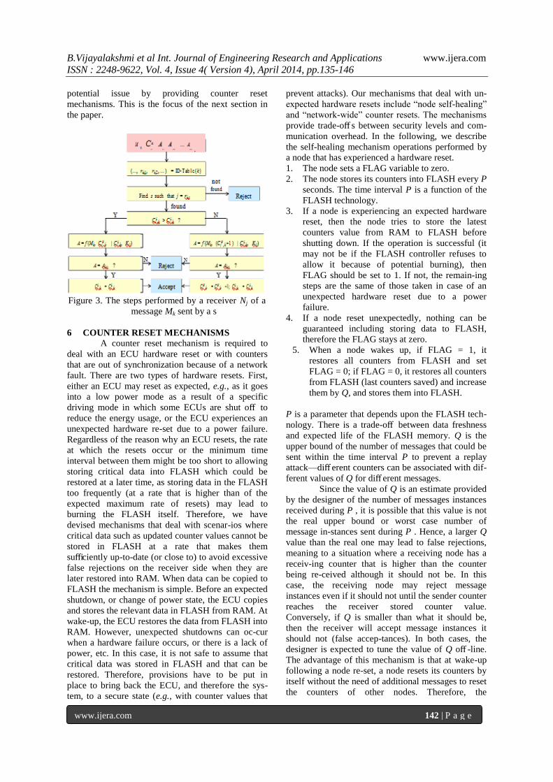
munication overhead. In the following, we describe
the self-healing mechanism operations performed by
a node that has experienced a hardware reset.
1. The node sets a FLAG variable to zero.
2. The node stores its counters into FLASH every P
seconds. The time interval P is a function of the
FLASH technology.
3. If a node is experiencing an expected hardware
reset, then the node tries to store the latest
counters value from RAM to FLASH before
shutting down. If the operation is successful (it
may not be if the FLASH controller refuses to
allow it because of potential burning), then
FLAG should be set to 1. If not, the remain-ing
steps are the same of those taken in case of an
unexpected hardware reset due to a power
failure.
4. If a node reset unexpectedly, nothing can be
guaranteed including storing data to FLASH,
therefore the FLAG stays at zero.
5. When a node wakes up, if FLAG = 1, it
restores all counters from FLASH and set
FLAG = 0; if FLAG = 0, it restores all counters
from FLASH (last counters saved) and increase
them by Q, and stores them into FLASH.
P is a parameter that depends upon the FLASH tech-
nology. There is a trade-off between data freshness
and expected life of the FLASH memory. Q is the
upper bound of the number of messages that could be
sent within the time interval P to prevent a replay
attack—diff erent counters can be associated with dif-
ferent values of Q for diff erent messages.
Since the value of Q is an estimate provided
by the designer of the number of messages instances
received during P , it is possible that this value is not
the real upper bound or worst case number of
message in-stances sent during P . Hence, a larger Q
value than the real one may lead to false rejections,
meaning to a situation where a receiving node has a
receiv-ing counter that is higher than the counter
being re-ceived although it should not be. In this
case, the receiving node may reject message
instances even if it should not until the sender counter
reaches the receiver stored counter value.
Conversely, if Q is smaller than what it should be,
then the receiver will accept message instances it
should not (false accep-tances). In both cases, the
designer is expected to tune the value of Q off -line.
The advantage of this mechanism is that at wake-up
following a node re-set, a node resets its counters by
itself without the need of additional messages to reset
the counters of other nodes. Therefore, the
B.Vijayalakshmi et al Int. Journal of Engineering Research and Applications www.ijera.com
ISSN : 2248-9622, Vol. 4, Issue 4( Version 4), April 2014, pp.135-146
www.ijera.com 143 | P a g e
communication overhead is minimized as no
network-wide counter synchroniza-tion is necessary.
However, as the parameter Q is an estimate, potential
false rejections or, even worse, false acceptances may
occur.
Besides the self-healing reset mechanism, we also
pro-pose a network-wide reset mechanism. The key
con-cepts are:
• A RESET message to set all counters of all
nodes to 0.
• A REQUEST message to achieve fault toler-
ance.
• New session keys to prevent replay attacks.
In this mechanism, because every counter is reset to
0, new session keys are required; otherwise, an at-
tacker could successfully replay-attack. Therefore, a
random generated number needs to be included in a
RESET message, as it is used to generate the new
session key for each node. We can further divide this
into two possible approaches. The first one is a ―dy-
namic‖ network reset where any node experiencing a
reset can generate a random number and send a
RESET message to all other nodes. The second ap-
proach is a ―static‖ network reset where only one spe-
cial master node can generate a random number and
send a RESET message to all other nodes.
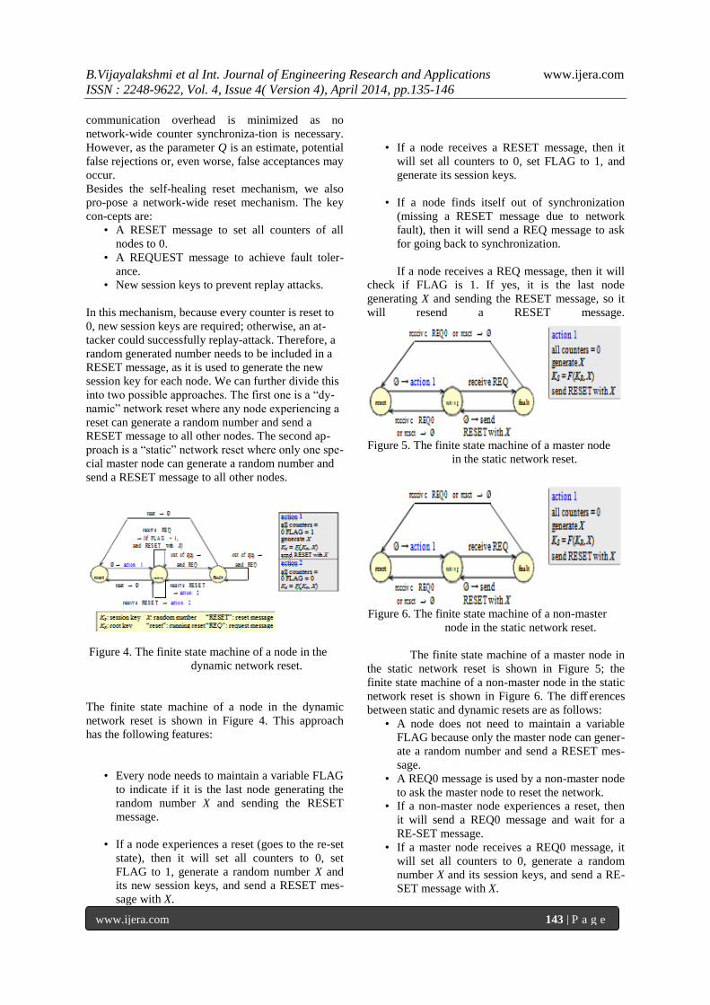
Figure 4. The finite state machine of a node in the
dynamic network reset.
The finite state machine of a node in the dynamic
network reset is shown in Figure 4. This approach
has the following features:
• Every node needs to maintain a variable FLAG
to indicate if it is the last node generating the
random number X and sending the RESET
message.
• If a node experiences a reset (goes to the re-set
state), then it will set all counters to 0, set
FLAG to 1, generate a random number X and
its new session keys, and send a RESET mes-
sage with X.
• If a node receives a RESET message, then it
will set all counters to 0, set FLAG to 1, and
generate its session keys.
• If a node finds itself out of synchronization
(missing a RESET message due to network
fault), then it will send a REQ message to ask
for going back to synchronization.
If a node receives a REQ message, then it will
check if FLAG is 1. If yes, it is the last node
generating X and sending the RESET message, so it
will resend a RESET message.
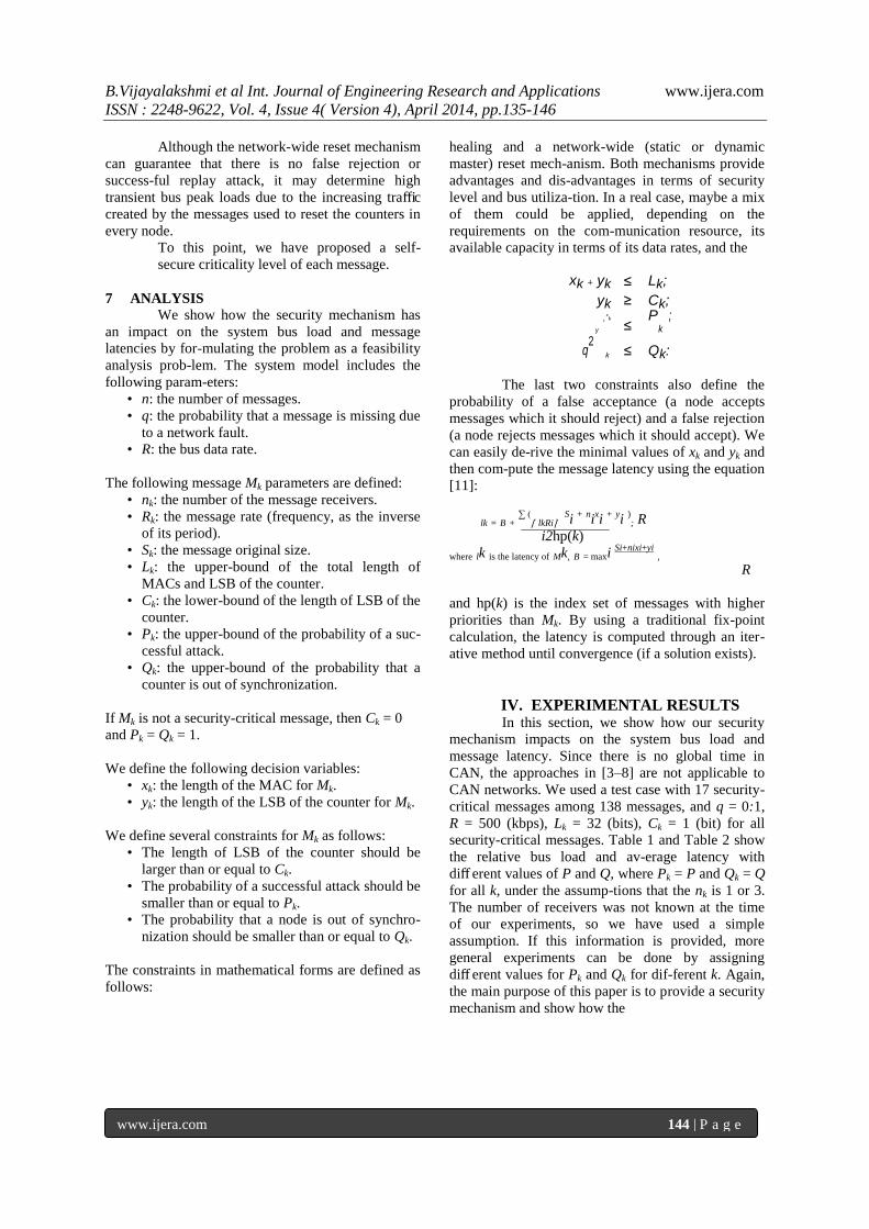
Figure 5. The finite state machine of a master node
in the static network reset.
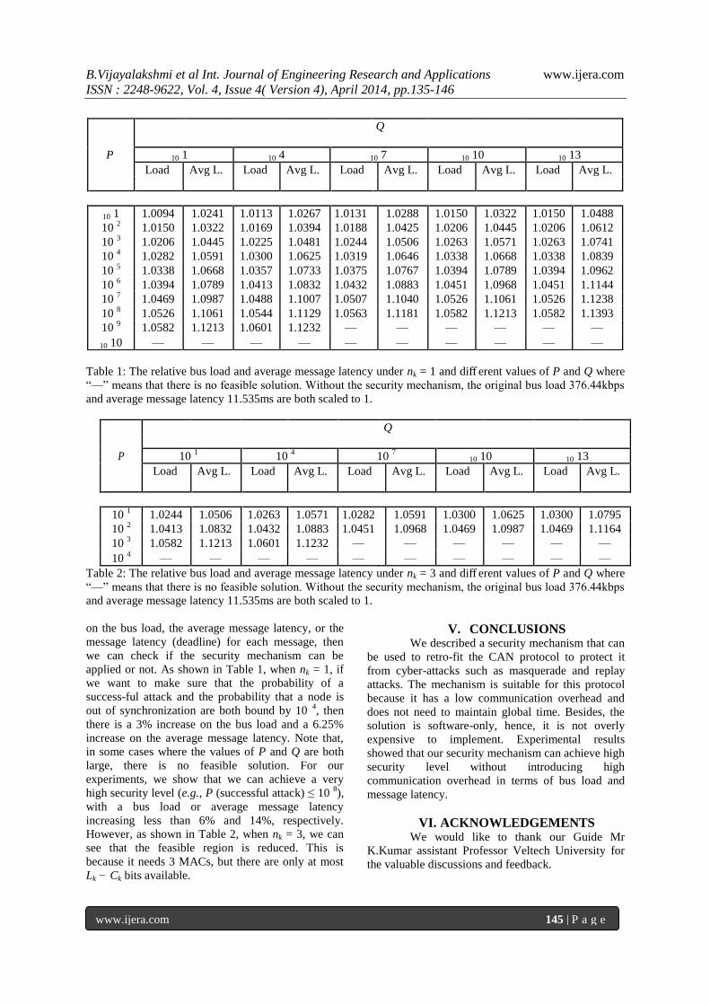
Figure 6. The finite state machine of a non-master
node in the static network reset.
The finite state machine of a master node in
the static network reset is shown in Figure 5; the
finite state machine of a non-master node in the static
network reset is shown in Figure 6. The diff erences
between static and dynamic resets are as follows:
• A node does not need to maintain a variable
FLAG because only the master node can gener-
ate a random number and send a RESET mes-
sage.
• A REQ0 message is used by a non-master node
to ask the master node to reset the network.
• If a non-master node experiences a reset, then
it will send a REQ0 message and wait for a
RE-SET message.
• If a master node receives a REQ0 message, it
will set all counters to 0, generate a random
number X and its session keys, and send a RE-
SET message with X.
B.Vijayalakshmi et al Int. Journal of Engineering Research and Applications www.ijera.com
ISSN : 2248-9622, Vol. 4, Issue 4( Version 4), April 2014, pp.135-146
www.ijera.com 144 | P a g e
Although the network-wide reset mechanism
can guarantee that there is no false rejection or
success-ful replay attack, it may determine high
transient bus peak loads due to the increasing traffic
created by the messages used to reset the counters in
every node.
To this point, we have proposed a self-
healing and a network-wide (static or dynamic
master) reset mech-anism. Both mechanisms provide
advantages and dis-advantages in terms of security
level and bus utiliza-tion. In a real case, maybe a mix
of them could be applied, depending on the
requirements on the com-munication resource, its
available capacity in terms of its data rates, and the
secure criticality level of each message.
7 ANALYSIS
We show how the security mechanism has
an impact on the system bus load and message
latencies by for-mulating the problem as a feasibility
analysis prob-lem. The system model includes the
following param-eters:
• n: the number of messages.
• q: the probability that a message is missing due
to a network fault.
• R: the bus data rate.
The following message Mk parameters are defined:
• nk: the number of the message receivers.
• Rk: the message rate (frequency, as the inverse
of its period).
• Sk: the message original size.
• Lk: the upper-bound of the total length of
MACs and LSB of the counter.
• Ck: the lower-bound of the length of LSB of the
counter.
• Pk: the upper-bound of the probability of a suc-
cessful attack.
• Qk: the upper-bound of the probability that a
counter is out of synchronization.
If Mk is not a security-critical message, then Ck = 0
and Pk = Qk = 1.
We define the following decision variables:
• xk: the length of the MAC for Mk.
• yk: the length of the LSB of the counter for Mk.
We define several constraints for Mk as follows:
• The length of LSB of the counter should be
larger than or equal to Ck.
• The probability of a successful attack should be
smaller than or equal to Pk.
• The probability that a node is out of synchro-
nization should be smaller than or equal to Qk.
The constraints in mathematical forms are defined as
follows:
xk + yk ≤ Lk;
yk ≥ Ck;
2 xk
≤ P ;
q2
y
k
k
≤ Qk:
The last two constraints also define the
probability of a false acceptance (a node accepts
messages which it should reject) and a false rejection
(a node rejects messages which it should accept). We
can easily de-rive the minimal values of xk and yk and
then com-pute the message latency using the equation
[11]:
lk = B + ∑ (
⌈ lkRi⌉ Si
+ nixi
+ yi
); R
i2hp(k)
where lk is the latency of Mk, B = maxi Si+nixi+yi
,
R
and hp(k) is the index set of messages with higher
priorities than Mk. By using a traditional fix-point
calculation, the latency is computed through an iter-
ative method until convergence (if a solution exists).
IV. EXPERIMENTAL RESULTS In this section, we show how our security
mechanism impacts on the system bus load and
message latency. Since there is no global time in
CAN, the approaches in [3–8] are not applicable to
CAN networks. We used a test case with 17 security-
critical messages among 138 messages, and q = 0:1,
R = 500 (kbps), Lk = 32 (bits), Ck = 1 (bit) for all
security-critical messages. Table 1 and Table 2 show
the relative bus load and av-erage latency with
diff erent values of P and Q, where Pk = P and Qk = Q
for all k, under the assump-tions that the nk is 1 or 3.
The number of receivers was not known at the time
of our experiments, so we have used a simple
assumption. If this information is provided, more
general experiments can be done by assigning
diff erent values for Pk and Qk for dif-ferent k. Again,
the main purpose of this paper is to provide a security
mechanism and show how the
B.Vijayalakshmi et al Int. Journal of Engineering Research and Applications www.ijera.com
ISSN : 2248-9622, Vol. 4, Issue 4( Version 4), April 2014, pp.135-146
www.ijera.com 145 | P a g e
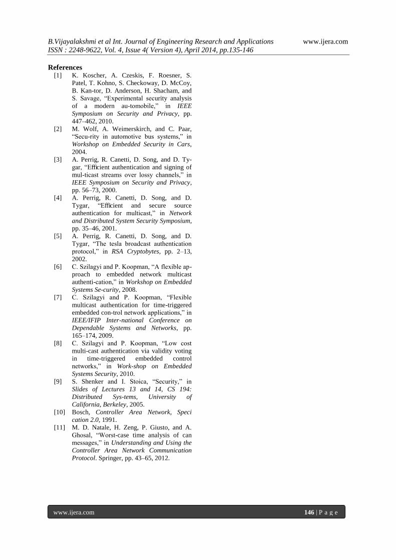
Table 1: The relative bus load and average message latency under nk = 1 and diff erent values of P and Q where
―—‖ means that there is no feasible solution. Without the security mechanism, the original bus load 376.44kbps
and average message latency 11.535ms are both scaled to 1.
Q
P 10 1 10
4 10
7 10 10 10 13
Load Avg L. Load Avg L. Load Avg L. Load Avg L. Load Avg L.
10 1 1.0244 1.0506 1.0263 1.0571 1.0282 1.0591 1.0300 1.0625 1.0300 1.0795
10 2 1.0413 1.0832 1.0432 1.0883 1.0451 1.0968 1.0469 1.0987 1.0469 1.1164
10 3 1.0582 1.1213 1.0601 1.1232 — — — — — —
10 4 — — — — — — — — — —
Table 2: The relative bus load and average message latency under nk = 3 and diff erent values of P and Q where
―—‖ means that there is no feasible solution. Without the security mechanism, the original bus load 376.44kbps
and average message latency 11.535ms are both scaled to 1.
on the bus load, the average message latency, or the
message latency (deadline) for each message, then
we can check if the security mechanism can be
applied or not. As shown in Table 1, when nk = 1, if
we want to make sure that the probability of a
success-ful attack and the probability that a node is
out of synchronization are both bound by 10 4, then
there is a 3% increase on the bus load and a 6.25%
increase on the average message latency. Note that,
in some cases where the values of P and Q are both
large, there is no feasible solution. For our
experiments, we show that we can achieve a very
high security level (e.g., P (successful attack) ≤ 10 8),
with a bus load or average message latency
increasing less than 6% and 14%, respectively.
However, as shown in Table 2, when nk = 3, we can
see that the feasible region is reduced. This is
because it needs 3 MACs, but there are only at most
Lk − Ck bits available.
V. CONCLUSIONS We described a security mechanism that can
be used to retro-fit the CAN protocol to protect it
from cyber-attacks such as masquerade and replay
attacks. The mechanism is suitable for this protocol
because it has a low communication overhead and
does not need to maintain global time. Besides, the
solution is software-only, hence, it is not overly
expensive to implement. Experimental results
showed that our security mechanism can achieve high
security level without introducing high
communication overhead in terms of bus load and
message latency.
VI. ACKNOWLEDGEMENTS We would like to thank our Guide Mr
K.Kumar assistant Professor Veltech University for
the valuable discussions and feedback.
Q
P 10 1 10 4 10 7 10 10 10 13
Load Avg L. Load Avg L. Load Avg L. Load Avg L. Load Avg L.
10 1 1.0094 1.0241 1.0113 1.0267 1.0131 1.0288 1.0150 1.0322 1.0150 1.0488
10 2 1.0150 1.0322 1.0169 1.0394 1.0188 1.0425 1.0206 1.0445 1.0206 1.0612
10 3 1.0206 1.0445 1.0225 1.0481 1.0244 1.0506 1.0263 1.0571 1.0263 1.0741
10 4 1.0282 1.0591 1.0300 1.0625 1.0319 1.0646 1.0338 1.0668 1.0338 1.0839
10 5 1.0338 1.0668 1.0357 1.0733 1.0375 1.0767 1.0394 1.0789 1.0394 1.0962
10 6 1.0394 1.0789 1.0413 1.0832 1.0432 1.0883 1.0451 1.0968 1.0451 1.1144
10 7 1.0469 1.0987 1.0488 1.1007 1.0507 1.1040 1.0526 1.1061 1.0526 1.1238
10 8 1.0526 1.1061 1.0544 1.1129 1.0563 1.1181 1.0582 1.1213 1.0582 1.1393
10 9 1.0582 1.1213 1.0601 1.1232 — — — — — —
10 10 — — — — — — — — — —
B.Vijayalakshmi et al Int. Journal of Engineering Research and Applications www.ijera.com
ISSN : 2248-9622, Vol. 4, Issue 4( Version 4), April 2014, pp.135-146
www.ijera.com 146 | P a g e
References [1] K. Koscher, A. Czeskis, F. Roesner, S.
Patel, T. Kohno, S. Checkoway, D. McCoy,
B. Kan-tor, D. Anderson, H. Shacham, and
S. Savage, ―Experimental security analysis
of a modern au-tomobile,‖ in IEEE
Symposium on Security and Privacy, pp.
447–462, 2010.
[2] M. Wolf, A. Weimerskirch, and C. Paar,
―Secu-rity in automotive bus systems,‖ in
Workshop on Embedded Security in Cars,
2004.
[3] A. Perrig, R. Canetti, D. Song, and D. Ty-
gar, ―Efficient authentication and signing of
mul-ticast streams over lossy channels,‖ in
IEEE Symposium on Security and Privacy,
pp. 56–73, 2000.
[4] A. Perrig, R. Canetti, D. Song, and D.
Tygar, ―Efficient and secure source
authentication for multicast,‖ in Network
and Distributed System Security Symposium,
pp. 35–46, 2001.
[5] A. Perrig, R. Canetti, D. Song, and D.
Tygar, ―The tesla broadcast authentication
protocol,‖ in RSA Cryptobytes, pp. 2–13,
2002.
[6] C. Szilagyi and P. Koopman, ―A flexible ap-
proach to embedded network multicast
authenti-cation,‖ in Workshop on Embedded
Systems Se-curity, 2008.
[7] C. Szilagyi and P. Koopman, ―Flexible
multicast authentication for time-triggered
embedded con-trol network applications,‖ in
IEEE/IFIP Inter-national Conference on
Dependable Systems and Networks, pp.
165–174, 2009.
[8] C. Szilagyi and P. Koopman, ―Low cost
multi-cast authentication via validity voting
in time-triggered embedded control
networks,‖ in Work-shop on Embedded
Systems Security, 2010.
[9] S. Shenker and I. Stoica, ―Security,‖ in
Slides of Lectures 13 and 14, CS 194:
Distributed Sys-tems, University of
California, Berkeley, 2005.
[10] Bosch, Controller Area Network, Speci
cation 2.0, 1991.
[11] M. D. Natale, H. Zeng, P. Giusto, and A.
Ghosal, ―Worst-case time analysis of can
messages,‖ in Understanding and Using the
Controller Area Network Communication
Protocol. Springer, pp. 43–65, 2012.