Embed Size (px)
Citation preview

2.1 INTRODUCTION OF HYDRO POWER PLANT Theory and working: The purpose of hydro electric plant is to provide from water flowing under pressure. Water flowing under pressure has two forms of energy kinetic and potential. Kinetic energy depends upon the mass velocity of flow while the potential energy exists as a result of difference in water level below the points of the turbine connects potential energy & kinetic energy possessed by water into mechanical power. Thus the turbine is a prime mover which can be coupled to generator producers. Details of hydro power plant are shown in Fig. 2.1.
Fig 2.1 Hydro power plant
Electric power: Hydro electric power can be developed when water continuously flowing under pressure is available. Dam is constructed to redirect the river water flow. Essential components of a hydro electric power plant are as follows:
Storage reservoir: The water available from an attachment area is stored in a reservoir so that it can be run to utilize the turbine for producing power according to requirement. Dam with control work: Dam is a structure ejected on a suitable site to provide for the storage of the water and created head. Dam may be built to make an artificial reservoir from the valley or it may be created in a river to control the flowing water. Water ways: Water ways is a passage through the water carried from the storage reservoir to the power houses. It consists of tunnel control, force pipe and penstock. Tunnel is a water passage made by cutting to mountain to save distance for bay in an enlarged section canal spread to accommodate the required width of Intake its function is to store temporarily water rejected to plant. Penstock: It is a pipe of large diameter carrying water under pressure from storage top tank. Power house: It is a building to house the turbine penstock and others for operating the machines.

Spill way: It is a safety valve for dam. Water after a certain level in the reservoir overflows through spill way without allowing the increase in water level in the reservoir particularly during rainy season. Surge tank: This helps in reducing the pressure surges developed due to sudden back flow of water as load on the turbine it reduced. Otherwise penstock will be damaged by the water hammer produced by sudden back flow.
Prime mover: It converts the potential energy of water to the mechanical energy. Head race: Water surface of reservoir level is called head race. Tail race: Water passing through turbine is discharged through tail race.
Fig 2.2 Turbine generator
2.2 CLASSIFICATION OF HYDRO POWER PIANT The hydro power plant can be classified according to the following four categories.
2.2.1 On the basis of availability of water and site (a) Run off river power station without pondage. (b) Reservoir power station. 2.2.2 Classification based on plant capacity (a) Micro hydel - less than 5mw (b) Medium capacity - -5 - 100mw (c) High capacity - 101 – 1000 mw (d) Super plants - more than >1000 mw 2.2.3 Depending on the load (a) Base load power plants

(b) Peak load power plants 2.2.4 On the basis of available head (a) High head - more than 180 m head (b) Medium head - between 30 – 180 m head (c) Low head - less than 30 m head.
2.3 HYDRO TURBINE Hydro turbine is the machine which is used to convert the energy of water into
mechanical energy, and mechanical energy developed by the turbine is used to run the electric generator which is directly coupled with the shaft of turbine. Turbine consists of wheel called runner, having the number of blades or buckets. 2.3.1 Classification of hydro turbines
Hydro turbines can be classified as under: (1)On the basis of head and the quantity of water available
(a) Impulse turbine - above 200 m -> high head and low flow rate (b) Francis turbine -between 30 m to 180 m head (medium head) and medium flow rate (c) Kaplan turbine -Low head and high flow rate -> head below the 30 m (2) On the basis of name of originator
(a) Pelton turbine - named in honour of allen pelton (1829 - 1908) of California (USA), is an impulse type of turbine used for high head and low discharge.
(b) Francis turbine: - named after James Bichens Francis (1815 - 1892) who was born is England and later went to USA, is a reaction type of turbine for medium high to medium low heads and medium small to medium large quantities of water.
(c) Kaplan turbine - named in honour of Victor Kaplan( 1878 - 1934) of Bruenn (Germany) is a reaction type of turbine for low heads and large blades.
(3) On the basis of direction of flow of water in the runner:

In tangential flow turbine of pelton type, the water strikes the runner tangential to the path of rotation. This path is the centre line of buckets which is, sometimes, known as pitch circle diameter or mean dia. of wheel.
In radial turbine, water enters radially and emerges out so that the discharge is parallel to the axis of the shaft. Modern Francis turbines have mixed flow runners.
In axial flow turbine, water flows parallel to the turbine shaft. In inward flow turbine, the water flows from the periphery towards centre of the wheel.
(4) On the basis of disposition of turbine shaft
Turbine shaft may be either vertical or horizontal. In modern turbine practice, Pelton turbines usually have horizontal shaft whereas the rest, specially the large units, have vertical shaft.
(6) On the basis of specific speed.
Specific speed
10 -20 - Slow pelton runner
Turbine 20 – 30 - medium pelton turbine Pelton turbine
30 – 35 - fast pelton runner
35 – 60 - Multi jet pelton runner
Francis turbine 60 – 120 - Slow Francis runner
120 – 180 - Medium Francis runner
180 – 300 - Fast Francis runner
Kaplan 300 – 1000 - Kaplan.
2.4 IMPULSE AND REACTION TURBINES: (a) Impulse turbine: The water is brought in through the penstock end into single nozzle. The whole pressure energy of water is converted into kinetic energy. The water coming out of

the nozzle in the form of a free jet is made strike on a series of buckets mounted on the periphery of a wheel. The water delivered to the wheel on a part of its circumference filling or striking only few of the buckets at the time. The wheel revolves in open air, there is no pressure difference in water at the inlet to the runner and the discharge therefore the casing of an impulse turbine has no hydraulic function to perform. It is necessary only to prevent splashing and to load the water to the race and also acts as a safeguard against accidents. This turbine is also known as a free jet turbine. In such type of turbine
P1 = P2 ; V1>>>V2 Vr1 Vr2 (Neglecting the losses in buckets)
(b) Reaction turbine: The reaction turbine operates with its when submerged in water. The water before entering the turbine has pressure as well as kinetic energy. All pressure energy is not transformed into kinetic energy as in case of impulse turbine. The moment on the wheel is produced by both kinetic and pressure energies. The water leaving the turbine has still some of the pressure as well as the kinetic energy. The pressure at the inlet to the turbine is much higher than the pressure at the outlet thus there is a possibility of water flowing through some passage other than the runner and escape without doing any work. Hence a casing is absolutely essential due to the difference of pressure in reaction turbine. For this type of turbine
P1>>P2 ; V1 > V2 and Vr1 <Vr2 2.5 HEADS OF A TURBINE
(1) Cross head: The difference between the head race level and tail race level when no water is flowing is known as cross head It is denoted by Hg.
Net head: It is also called effective head and is defined as the head available at the inlet
of the turbine. When water is flowing from head race to the turbine, a loss of head due to friction between the water and penstock occurs. There are losses due to bend, pipe, fitting, loss at entrance of pen stock etc. Suppose frictional losses are hf between penstock and turbine. so
hf is calculated by hf hf
where D = dia of penstock. L =length of penstock V= velocity of water.
2.6 CONSTRUCTION DETAILS OF PELTON TURBINE:
Theory: This is the only turbine that it in common use, named in the honour of Mr. L.A. Pelton (1829 - 1908) of California, U.S.A. Who contributed much to its development and got it patented m 1889. It is an efficient turbine particularly suited to high heads and therefore required a comparatively less quantity of water. Pelton turbine is an impulse turbine which is used to utilize high head for generation of power by converting it into kinetic energy by
Net head (H) = Gross head (Hg) + hf(friction head loss)

means of a spear and nozzle arrangement. The water leaves the nozzle in the form of jet, then strikes the bucket of the turbine. After striking the bucket the jet of water is deflected through an angle of 16- and 170 degree. While passing over the bucket the velocity of water is reduced and hence an impulsive force is supplied to them which is turn start rotating. The water impinging on the bucket of a Pelton turbine is shown in Fig 2.3.
Fig 2.3
Construction detail The main components of a Pelton Turbine are:
(a) Penstock: It is a large size conduit with conveys water from the higher level reservoir turbine, depending upon low head or the high head installations. A penstock may be of wood, concrete or steel. For the regulation of the turbine, penstock is provided with control valves. The entry of debris is prevented by the provision of screens called trash racks.
(b) Spear and Nozzle: At the downstream end of penstock la fitted with an efficient nozzle that conveys the whole hydraulic energy of water into high speed jet. To regulate the water flow nozzle is provided with spear or needle while can be moved forward or backward. This is controlled either by hand wheel or governing.
Fig. 2.4. Spear rod nozzle
(c) Runner and Bucket: The turbine rotor called runner is actually a circular disk carrying a number of cup shaped buckets and which are equidistantly around the periphery of the disk. For low heads buckets are made of cast iron and for higher head these are made of stainless steel. Further the inner surface of the buckets is polished to prevent the factional resistance of the water jet The water is equally distributed to the hemispherical buckets by the ridge or splitter There is a cut or notch on the side of bucket which ensures the face of bucket to the jet only when it is in a proper position. This position occurs when the face of the bucket and jet are at 90o to each other.
y
A
x
VEntering jet
j
Exiting jet(nil velocity)
A
r
z
Torqueon shaft
Controlsurface
Nozzle
Turbineshaft
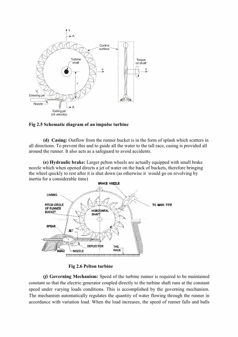
Fig 2.5 Schematic diagram of an impulse turbine
(d) Casing: Outflow from the runner bucket is in the form of splash which scatters in
all directions. To prevent this and to guide all the water to the tall race, casing is provided all around the runner. It also acts as a safeguard to avoid accidents.
(e) Hydraulic brake: Larger pelton wheels are actually equipped with small brake
nozzle which when opened directs a jet of water on the back of buckets, therefore bringing the wheel quickly to rest after it is shut down (as otherwise it would go on revolving by inertia for a considerable time)
Fig 2.6 Pelton turbine
(f) Governing Mechanism: Speed of the turbine runner is required to be maintained constant so that the electric generator coupled directly to the turbine shaft runs at the constant speed under varying loads conditions. This is accomplished by the governing mechanism. The mechanism automatically regulates the quantity of water flowing through the runner in accordance with variation load. When the load increases, the speed of runner falls and balls
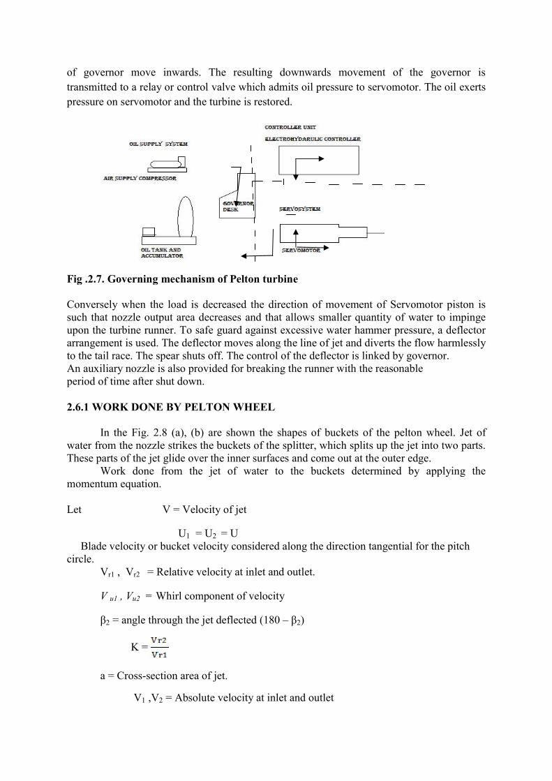
of governor move inwards. The resulting downwards movement of the governor is transmitted to a relay or control valve which admits oil pressure to servomotor. The oil exerts pressure on servomotor and the turbine is restored.
Fig .2.7. Governing mechanism of Pelton turbine Conversely when the load is decreased the direction of movement of Servomotor piston is such that nozzle output area decreases and that allows smaller quantity of water to impinge upon the turbine runner. To safe guard against excessive water hammer pressure, a deflector arrangement is used. The deflector moves along the line of jet and diverts the flow harmlessly to the tail race. The spear shuts off. The control of the deflector is linked by governor. An auxiliary nozzle is also provided for breaking the runner with the reasonable period of time after shut down. 2.6.1 WORK DONE BY PELTON WHEEL
In the Fig. 2.8 (a), (b) are shown the shapes of buckets of the pelton wheel. Jet of water from the nozzle strikes the buckets of the splitter, which splits up the jet into two parts. These parts of the jet glide over the inner surfaces and come out at the outer edge.
Work done from the jet of water to the buckets determined by applying the momentum equation. Let V = Velocity of jet
U1 = U2 = U Blade velocity or bucket velocity considered along the direction tangential for the pitch circle.
Vr1 , Vr2 = Relative velocity at inlet and outlet.
V u1 , Vu2 = Whirl component of velocity
β2 = angle through the jet deflected (180 – β2)
K =
a = Cross-section area of jet.
V1 ,V2 = Absolute velocity at inlet and outlet

(a)inlet velocity triangle (b) outlet velocity triangle
(c)Inlet velocity triangle (d) Outlet velocity triangle
Fig.2.8. Velocity diagram of pelton wheel (a),(b),(c) and (d).
From the inlet velocity triangle.
Vr1 = (V - u) ………..(1)
Where u =
And Vu1 = V1 = Vr1 +u1 ……….(2)
From the outlet velocity triangle
Vu2 = (U – Vr2 cosβ2)
K =

Or Vr2 = KVr1
Vr2 = (U – KVr1(cos β2)) ………(3)
Value of Vr1 from equation (1)
Vr2 = [U – K(V - u) cos β2] ………(4)
Exerted force = Rate of change of momentum
= ρθ (Vu1 – Vu2)
= ρθ[(V - u)+K(V - u)cos β2]
… ……(5)
Flow rate Q = area x velocity of jet
= a x V.
………(6)
Workdone (Wnet) = Fx x u
……..(7)
K.E of jet = ½ mV2
= ½ ρQV2
=1/2 ρaV3 …………(8)
From the equations (7) and (8)
(ηH) ……(9)
(ηH) ………..(10)
Differential with respect to (u)
(ηH) = ……….(11)
= ( )
Fx = ρQ(V - u)(1+K(cos β2))
Fx = ρaV(V - u)(1+K(cos β2))
Wnet = ρaVu(V - u)(1+K(cos β2))
(ηH) = [2V – 4u] = 0 ………..(12)
0.
V =2u.
Or ……………(13)
Max (ηH) =
…… ………(14)
…………….(15)
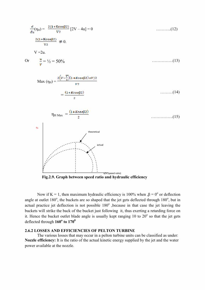
Now if K = 1, then maximum hydraulic efficiency is 100% when ,β = 0o or deflection angle at outlet 180o, the buckets are so shaped that the jet gets deflected through 180o, but in actual practice jet deflection is not possible 180o ,because in that case the jet leaving the buckets will strike the back of the bucket just following it, thus exerting a retarding force on it. Hence the bucket outlet blade angle is usually kept ranging 10 to 20o so that the jet gets deflected through 160o to 1700
2.6.2 LOSSES AND EFFICIENCIES OF PELTON TURBINE The various losses that may occur in a pelton turbine units can be classified as under:
Nozzle efficiency: It is the ratio of the actual kinetic energy supplied by the jet and the water power available at the nozzle.
0.5 1
ηh
u/v (speed ratio)
theoretical
actual
= ½ = 50%
=
ηH Max =
Fig.2.9. Graph between speed ratio and hydraulic efficiency

(ρgQH) head loss due ½ ρQV2
To friction
Nozzle efficiency = =
(η Nozzle) = [ ]2 ……………(16)
Velocity coefficient (Cr ) : Ratio of the velocity of jet and the (υ) theoretical velocity is called the velocity coefficient. It is represented by Cv, value of Cv varies between 0.9 to 1.
(i) Hydraulic efficiency or wheel efficiency: It is the ratio of power developed by the turbine runner to the net power supplied by the water at the entrance to the turbine (nozzle outlet).
η H=
(1/2 ρQV2) QθV(V - u)( )
η H
Penstock Nozzle
ηnozzle = Cv2
Nozzle Turbine runner runner
Hydraulic losses:
Blade friction losses
Eddy formation losses.
Leakage losses
Other friction losses.
…………..(18)
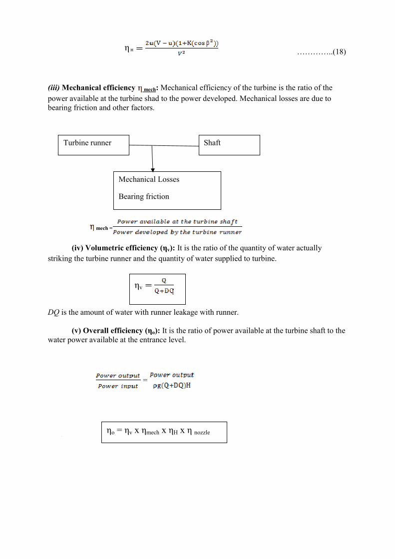
(iii) Mechanical efficiency mech: Mechanical efficiency of the turbine is the ratio of the power available at the turbine shad to the power developed. Mechanical losses are due to bearing friction and other factors.
mech =
(iv) Volumetric efficiency (ηv): It is the ratio of the quantity of water actually striking the turbine runner and the quantity of water supplied to turbine.
DQ is the amount of water with runner leakage with runner.
(v) Overall efficiency (ηo): It is the ratio of power available at the turbine shaft to the water power available at the entrance level.
=
ηo = ηv x ηmech x ηH x η nozzle
Turbine runner Shaft
Mechanical Losses
Bearing friction
ηv
η H

Fig 2.10 power loss diagram for pelton turbine 2.6.4 SOME DIMENSIONLESS NUMBER IN PELTON TURBINE
(1) Velocity coefficient or velocity ratio (Cv), It is defined as the ratio of the jet velocity and the theoretical velocity of water.
Cv
Value of Cv varies between 0.9 to 1.
(2) Speed ratio (Cv): It is defined as the ratio of the peripheral velocity of runner and the theoretical velocity of water.
Speed ratio(Cu) = …………..(21)
Value of CH varies between 0.45 to 0.6.
(3) Jet ratio (m): It is the ratio of dia. of runner wheel (D) and the dia. of the jet (d).
m = …………….....(22)
(4) Number of buckets (n) =05 m x 15 …………....(23) 2.6.5 DESIGN of PELT0N WHEEL
Reservoir Penstock End
Shaft End Nozzle End
Turbine End
Generater
Frictional head losses in penstock
Frictional head loss in nozzle
Hydraulic loss
Mechanical losses
Generator losses

A Pelton wheel is required to be designed to develop power (P) while working under head (H) and running speed (N). The suitable value of overall efficiency (ηo) velocity ratio (Cv), speed ratio (Cu),jet ratio are assumed.
1. Determine the discharge Q required to develop power P.
ηo
Q …………….(24)
Calculate the jet velocity V =Cv 2gH (from equation 20) Calculate the area of jet required
Total area (a) = …………..(25)
Now calculate speed of runner.
U = Cu (From equation 21)
(5) Wheel diameter (D), obtained
D = ………..(26)
(6) Assuming a suitable value of jet ratio (m) dia of the jet can be calculated.
D = …………(27)
(7) Now number of jet (n) = ……………(28)
If the n value is fractional, it is rounded up to next higher number and keeping the
value of m more or less same. (8) Total number of buckets can be determined by
= 0.5m + 15 Bucket dimension axial width (B) = 3d to 4d radial length (l) = 2d to 3d. Depth (T)= 0.8 to 1.2 d where d = dia. of jet.
2.6.6 MULTIPLE JET PELTON WHEEL
Usually, the power developed by a pelton wheel with single nozzle is quite low and insufficient. Therefore, to develop more power under constant head (H), more discharge should strike the buckets Since P = pgQH ………....(29) Quantities of flow
Discharge of (Q) = Cv x u …………..(30)

Value of Cv is not changed hence more discharge means more area of cross-section of nozzle Now. If the diameter of the nozzle is increased. the diameter D of the wheel shall be increased to keep the constant value of a Jet ratio (m). But it is not deferrable to increase the wheel diameter. There more area of the cross-section of the jet can be provided by increasing the number of nozzle to 2 load or at the maximum 6. If the number of nozzles is increased beyond 6, the water from one nozzle will interfere with that of the other nozzle.
Specific speed (N) = ……………..(31)
2.6.7. TYPES OF PELTON RUNNERS
Vr2 V2 Vr2 V2 = Vf2
β2 Vf2 θ2 β2 θ2
Vu2 U2
U2
Vu2 = Positive Vu2 =0
Vr2
V2 Vf2
U2 Vu2
Vu2 = Negative
Fig. 2.11 Different runner velocity triangles.
2.6.8 LOAD CHANGE FOR PELTON TURBINE
Turbine is directly coupled with generator so that it is running with constant speed (u), so u is constant when load changes,
speed ratio = constant means jet velocity does not change so adjust to a change
in turbine load to change the input power (pgQH). In the input power pgQH
p, g, Q = H = Constant Q change, Q = a x . ( = Const.)
So Q changes with area of water jet Due to load change sudden reduction of annular area in the jet may lead to setting up
of water hammer in the pipe, which may cause excessive inertia pressure in the pipe line due to which the pipe may burst Surge tanks are used in the case of high and medium head hydro power plants where the penstock is very long, and fore bays are suitable for medium and low head hydro power plants where the length of penstock is short.
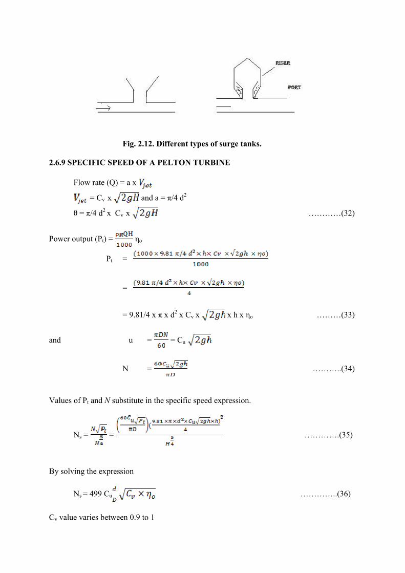
Fig. 2.12. Different types of surge tanks.
2.6.9 SPECIFIC SPEED OF A PELTON TURBINE Flow rate (Q) = a x
= Cv x and a = π/4 d2
θ = π/4 d2 x Cv x …………(32)
Power output (Pt) = ηo
Pt =
=
= 9.81/4 x π x d2 x Cv x x h x ηo ………(33)
and u = = Cu
N = ………..(34)
Values of Pt and N substitute in the specific speed expression.
Ns = = ………….(35)
By solving the expression
Ns = 499 Cu …………..(36)
Cv value varies between 0.9 to 1

and Cu, value varies between 0.45 to 0.6. ASSUME Cu=0.46, Cv =0.97, ηo= 0.86
Specific speed (Ns) = 203 ( ) = 203 M. ……………..(37)
Ns = 203 m. If the multiple jet pelton wheel is with n jet then specific speed Ns=(203√N)m …………….(38)