Embed Size (px)
Citation preview
(Ref: 1810)
8070CNCCustomizing guide (FGUIM & API).
BLANK PAGE
·2·
MACHINE SAFETY
It is up to the machine manufacturer to make sure that the safety of the machineis enabled in order to prevent personal injury and damage to the CNC or to theproducts connected to it. On start-up and while validating CNC parameters, itchecks the status of the following safety elements. If any of them is disabled, theCNC shows the following warning message.
• Feedback alarm for analog axes.
• Software limits for analog and sercos linear axes.
• Following error monitoring for analog and sercos axes (except the spindle)both at the CNC and at the drives.
• Tendency test on analog axes.
FAGOR AUTOMATION shall not be held responsible for any personal injuries orphysical damage caused or suffered by the CNC resulting from any of the safetyelements being disabled.
DUAL-USE PRODUCTS
Products manufactured by FAGOR AUTOMATION since April 1st 2014 willinclude "-MDU" in their identification if they are included on the list of dual-useproducts according to regulation UE 428/2009 and require an export licensedepending on destination.
TRANSLATION OF THE ORIGINAL MANUAL
This manual is a translation of the original manual. This manual, as well as thedocuments derived from it, have been drafted in Spanish. In the event of anycontradictions between the document in Spanish and its translations, the wordingin the Spanish version shall prevail. The original manual will be labeled with thetext "ORIGINAL MANUAL".
HARDWARE EXPANSIONS
FAGOR AUTOMATION shall not be held responsible for any personal injuries orphysical damage caused or suffered by the CNC resulting from any hardwaremanipulation by personnel unauthorized by Fagor Automation.
If the CNC hardware is modified by personnel unauthorized by FagorAutomation, it will no longer be under warranty.
COMPUTER VIRUSES
FAGOR AUTOMATION guarantees that the software installed contains nocomputer viruses. It is up to the user to keep the unit virus free in order toguarantee its proper operation. Computer viruses at the CNC may cause it tomalfunction.
FAGOR AUTOMATION shall not be held responsible for any personal injuries orphysical damage caused or suffered by the CNC due a computer virus in thesystem.
If a computer virus is found in the system, the unit will no longer be under warranty.
All rights reserved. No part of this documentation may be transmitted,transcribed, stored in a backup device or translated into another languagewithout Fagor Automation’s consent. Unauthorized copying or distributing of thissoftware is prohibited.
The information described in this manual may be subject to changes due totechnical modifications. Fagor Automation reserves the right to change thecontents of this manual without prior notice.
All the trade marks appearing in the manual belong to the corresponding owners.The use of these marks by third parties for their own purpose could violate therights of the owners.
It is possible that CNC can execute more functions than those described in itsassociated documentation; however, Fagor Automation does not guarantee thevalidity of those applications. Therefore, except under the express permissionfrom Fagor Automation, any CNC application that is not described in thedocumentation must be considered as "impossible". In any case, FagorAutomation shall not be held responsible for any personal injuries or physicaldamage caused or suffered by the CNC if it is used in any way other than asexplained in the related documentation.
The content of this manual and its validity for the product described here has beenverified. Even so, involuntary errors are possible, hence no absolute match isguaranteed. However, the contents of this document are regularly checked andupdated implementing the necessary corrections in a later edition. We appreciateyour suggestions for improvement.
The examples described in this manual are for learning purposes. Before usingthem in industrial applications, they must be properly adapted making sure thatthe safety regulations are fully met.
Customizing guide (FGUIM & API).
CNC 8070
·3·
(REF: 1810)
I N D E X
About the product - CNC 8070 ..................................................................................................... 7Declaration of CE conformity and warranty conditions ................................................................11Version history - CNC 8070 ........................................................................................................ 13Safety conditions ........................................................................................................................ 17Returning conditions ................................................................................................................... 21CNC maintenance ...................................................................................................................... 23
CHAPTER 1 BEFORE STARTING.
1.1 Manual contents............................................................................................................. 261.2 Conventions used in this manual. .................................................................................. 27
CHAPTER 2 GENERAL DESCRIPTION OF THE FGUIM.
2.1 Work environment. Interface description. ...................................................................... 302.2 The tool bars. ................................................................................................................. 322.3 The menu bar................................................................................................................. 332.4 The dialog boxes............................................................................................................ 34
CHAPTER 3 MMC8070 AND STANDARD COMPONENTS.
3.1 Design of the MMC8070 and the standard components................................................ 353.2 CNC Properties.............................................................................................................. 363.3 Properties of standard components ............................................................................... 38
CHAPTER 4 CONFIGURABLE COMPONENTS
4.1 About the configurable components. ............................................................................. 444.2 Overall design. Adding and deleting components and user cycles................................ 454.3 Designing a component. Adding and deleting components........................................... 464.4 Designing the pages of the components........................................................................ 474.4.1 Working with a group of controls................................................................................ 49
CHAPTER 5 CONFIGURABLE COMPONENTS LIST OF CONTROLS.
5.1 Properties of the controls. .............................................................................................. 535.1.1 Variables and expressions in the controls.................................................................. 545.1.2 Texts in different languages in the controls................................................................ 575.2 "Static" control. .............................................................................................................. 585.3 "Varx" control. ............................................................................................................... 605.3.1 Methods of the "VarX" control to be used in scripts. .................................................. 625.4 "Progx" control. ............................................................................................................. 635.5 "Gs" and "Ms" control. ................................................................................................... 655.6 "EditCtrl" control. ........................................................................................................... 665.7 "GrafCtrl" control. .......................................................................................................... 685.8 "Tejec" control. .............................................................................................................. 705.9 "TimeX" control. ............................................................................................................ 725.10 "EjesX" control. ............................................................................................................. 735.10.1 Methods of the "EjesX" control to be used in scripts.................................................. 755.11 "PictX" control. .............................................................................................................. 765.12 "Multistatic" control. ....................................................................................................... 775.12.1 Methods of the "Multistatic" control to be used in scripts. .......................................... 805.13 "AnMeter" control. ......................................................................................................... 815.14 "BarMeter" control. ........................................................................................................ 835.15 "AviCtrl" control. ............................................................................................................ 855.16 "Histogram" control. ...................................................................................................... 865.17 "ButtonCtrl" control. ....................................................................................................... 885.17.1 Events of the "ButtonCtrl" control to be used in scripts.............................................. 895.18 "EditX" control. .............................................................................................................. 905.18.1 Methods of the "EditCtrl" control to be used in scripts. .............................................. 925.19 "WebCamX" control. ..................................................................................................... 935.19.1 Functions of the "WebCamX" control to be used in scripts........................................ 945.20 "ProgStackX" control. .................................................................................................... 955.21 "CSGrafCtrl" control. ..................................................................................................... 965.22 "Data" control. ............................................................................................................... 97
Customizing guide (FGUIM & API).
CNC 8070
·4·
(REF: 1810)
5.22.1 Methods of the "Dato" control to be used in scripts. .................................................. 995.23 "GridX" control. ........................................................................................................... 1005.23.1 Methods of the "GridX" control to be used in scripts................................................ 1035.24 “F3DGrafCtrl” control. ................................................................................................. 1075.24.1 Methods of the "F3DGrafCtrl" control to be used in scripts...................................... 1085.25 “F3DGrafCtrl SIMU” control. ....................................................................................... 1095.25.1 Methods of the "F3DGrafCtrl SIMU" control to be used in scripts............................ 110
CHAPTER 6 CONFIGURABLE COMPONENTS SCREEN CUSTOMIZING WITHOUT SCRIPTS.
6.1 Defining the softkey menus. ....................................................................................... 1116.1.1 Defining the structure of the softkey menu. ............................................................. 1126.1.2 Defining the properties of a softkey. ........................................................................ 1136.2 Defining the properties of a page. ............................................................................... 1156.2.1 Cycle (subroutine or blocks associated with the user cycle).................................... 1166.2.2 Title of the cycle. ...................................................................................................... 1166.2.3 Treatment of the [START] key. ................................................................................ 1166.2.4 Lauch components................................................................................................... 1176.2.5 Treatment of the [ESC] key...................................................................................... 1176.2.6 Treatment of the "scroll arrows" keys....................................................................... 1176.2.7 Write variables. ........................................................................................................ 1176.2.8 Graphic elements (show controls, change properties, etc). ..................................... 1186.2.9 Activate deactivate pages. ....................................................................................... 1186.2.10 Programming assistance. ........................................................................................ 1196.3 Interface operation commands. ................................................................................... 1206.4 Cut, copy and paste the softkey menus and/or definitions of the pages. .................... 122
CHAPTER 7 EXAMPLES OF CUSTOMIZING WITHOUT SCRIPTS.
7.1 Create a user component that is accessible from manual mode. ................................ 1237.1.1 Definition of a user component. ............................................................................... 1237.1.2 Definition of a variable (Varx control). ...................................................................... 1247.1.3 Definition of a text (Static control). ........................................................................... 1247.1.4 Definition of a variable color graphic element (Static control). ................................. 1257.1.5 Defining a button to activate the PLC mark (Button control). ................................... 1297.1.6 Definition of the component access softkey............................................................. 1307.1.7 Treatment of the escape key. .................................................................................. 1327.2 Creating a user cycle. .................................................................................................. 1337.2.1 Defining a user component and the number of pages. ............................................ 1347.2.2 Definition of the component access softkey............................................................. 1357.2.3 Defining the cycle softkeys. ..................................................................................... 1377.2.4 Page 1. Defining of the name of the axes (Static control)........................................ 1397.2.5 Page 1. Defining the axes coordinates (Data control). ............................................ 1407.2.6 Page 1. Defining the spindle data (Multistatic control). ............................................ 1427.2.7 Page 1. Defining the title (Static control).................................................................. 1437.2.8 Page 1. Defining an image (Pictx control)................................................................ 1437.2.9 Page 1. Defining the cycle properties. ..................................................................... 1447.2.10 Page 1. Defining the subroutine............................................................................... 1457.2.11 Page 2. Copy the controls on page 1 to page 2....................................................... 1467.2.12 Page 2. Modifying controls....................................................................................... 1467.2.13 Page 2. Modifying cycle properties. ......................................................................... 1477.2.14 Page 2. Defining the subroutine............................................................................... 147
CHAPTER 8 CONFIGURABLE COMPONENTS. SCRIPTS.
8.1 Script programming assistance. .................................................................................. 1508.2 Texts in different languages in the scripts. .................................................................. 1518.3 Servers for the scripts. ................................................................................................. 1538.4 –Global– server. .......................................................................................................... 1548.4.1 Methods of the -Global- server ................................................................................ 1548.4.2 Events of the -Global- server ................................................................................... 1618.5 –Dialog– server............................................................................................................ 1668.6 –Menu– server. ............................................................................................................ 1688.7 Creating a resource library. ......................................................................................... 170
CHAPTER 9 API8070.
9.1 Steps to follow to use the API8070.............................................................................. 1749.2 Servers of the API8070. .............................................................................................. 1759.2.1 Server –Cnc8070.Variables– ................................................................................... 1769.2.2 Servidor –Cnc8070.Utilities–.................................................................................... 1819.2.3 Server –Cnc8070.Kernel–........................................................................................ 1839.2.4 Server –Cnc8070.Axes– .......................................................................................... 1919.2.5 Server –Cnc8070.GrafData– ................................................................................... 193
Customizing guide (FGUIM & API).
CNC 8070
·5·
(REF: 1810)
9.2.6 Server –Cnc8070.FixtureTable– .............................................................................. 1999.2.7 Server –Cnc8070.OriginTable–................................................................................ 2009.2.8 Server –Cnc8070.PparamTable–............................................................................. 2019.2.9 Server –Cnc8070.Parameter– ................................................................................. 2039.2.10 Server –Cnc8070.ParameterList–............................................................................ 2059.2.11 Server –Cnc8070.MachineParameters– .................................................................. 2079.2.12 Server –Cnc8070.Plc– ............................................................................................. 2109.2.13 Server –Cnc8070.Jog– ............................................................................................ 2119.2.14 Server –Cnc8070.error–........................................................................................... 2159.2.15 Server –Cnc8070.ToolTable– .................................................................................. 2169.2.16 Server –Cnc8070.FCITool– ..................................................................................... 2199.2.17 Server –Cnc8070.FCIEdge– .................................................................................... 2219.2.18 Server –Cnc8070.MagazineTable–.......................................................................... 2239.2.19 Server –Cnc8070.FCIPlaceStorage–....................................................................... 2259.2.20 Server –Cnc8070.MzInfor– ...................................................................................... 2279.2.21 Server –Cnc8070.OpcServer– ................................................................................. 2289.2.22 Server –Cnc8070.remoteVariables– ........................................................................ 2299.2.23 Server –Cnc8070.FCApiTables– ............................................................................. 2309.2.24 Server –Cnc8070.FCF3DGrafCtrlHandles–............................................................. 2319.2.25 Server –Cnc8070.HelpEditCtrl– ............................................................................... 2329.2.26 Server –Cnc8070.oscilloscope–............................................................................... 2339.2.27 Server –Cnc8070.KernelMParam– .......................................................................... 2359.2.28 Server –Cnc8070.KeystrokeEngine– ....................................................................... 2449.2.29 Server –Cnc8070.AutoAdjust–................................................................................. 2459.2.30 Server –Cnc8070.SintaxFun– .................................................................................. 2509.2.31 Server –Cnc8070.FCIItemGraf2D–.......................................................................... 2519.2.32 Server –Cnc8070.FCIDecoder–............................................................................... 2539.2.33 Server –Cnc8070.FCTechTable– ............................................................................ 2559.3 Notifications of the servers........................................................................................... 2639.3.1 Notifications of the Api8070. .................................................................................... 2649.4 API examples............................................................................................................... 2699.4.1 Example in c# language (FAPI8070). ...................................................................... 2699.4.2 Example in VB.NET language.................................................................................. 2719.4.3 Example in C++ language (RemoteConnect). ......................................................... 274

BLANK PAGE
·6·
Customizing guide (FGUIM & API).
CNC 8070
·7·
(REF: 1810)
ABOUT THE PRODUCT - CNC 8070
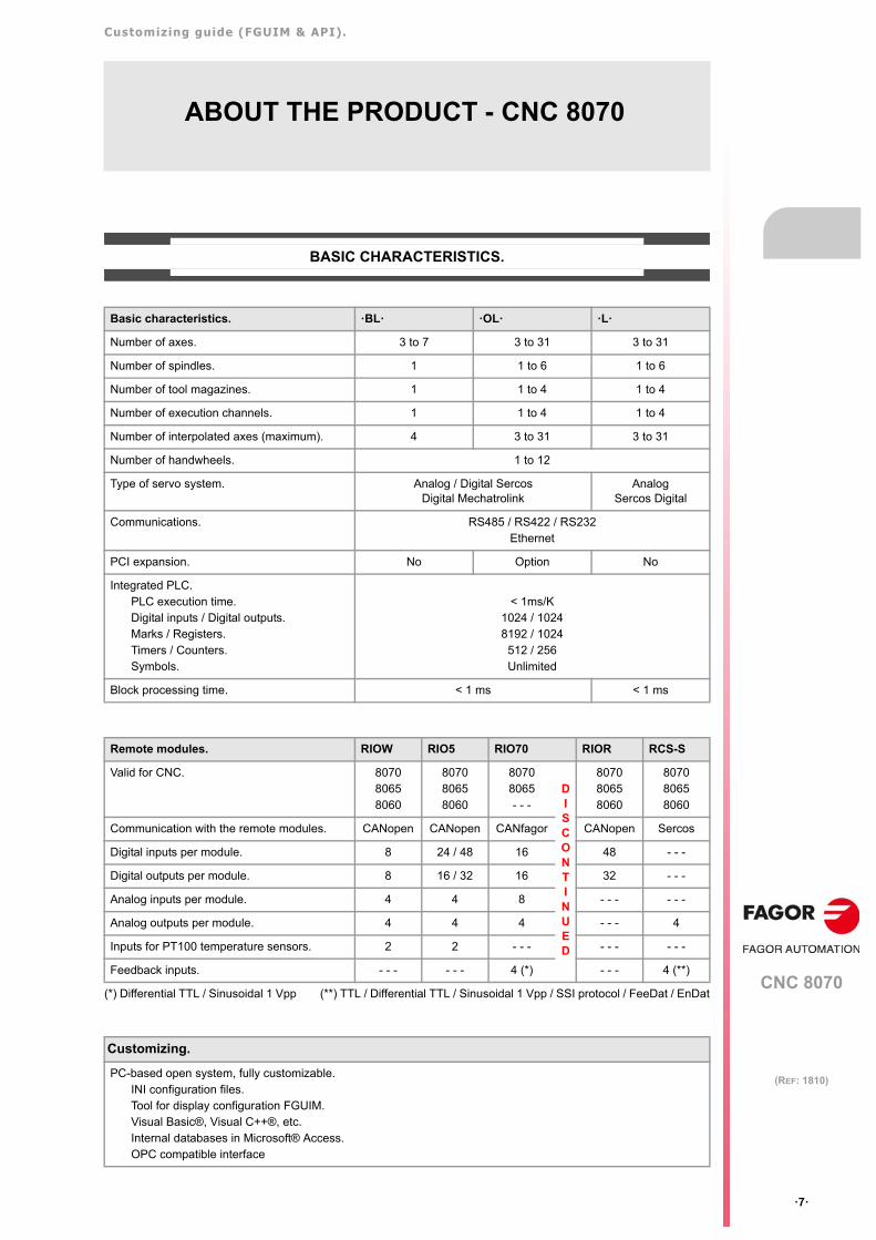
BASIC CHARACTERISTICS.
(*) Differential TTL / Sinusoidal 1 Vpp (**) TTL / Differential TTL / Sinusoidal 1 Vpp / SSI protocol / FeeDat / EnDat
Basic characteristics. ·BL· ·OL· ·L·
Number of axes. 3 to 7 3 to 31 3 to 31
Number of spindles. 1 1 to 6 1 to 6
Number of tool magazines. 1 1 to 4 1 to 4
Number of execution channels. 1 1 to 4 1 to 4
Number of interpolated axes (maximum). 4 3 to 31 3 to 31
Number of handwheels. 1 to 12
Type of servo system. Analog / Digital SercosDigital Mechatrolink
AnalogSercos Digital
Communications. RS485 / RS422 / RS232Ethernet
PCI expansion. No Option No
Integrated PLC. PLC execution time.Digital inputs / Digital outputs.Marks / Registers.Timers / Counters.Symbols.
< 1ms/K1024 / 10248192 / 1024
512 / 256Unlimited
Block processing time. < 1 ms < 1 ms
Remote modules. RIOW RIO5 RIO70 RIOR RCS-S
Valid for CNC. 807080658060
807080658060
80708065- - -
DISCONTINUED
807080658060
807080658060
Communication with the remote modules. CANopen CANopen CANfagor CANopen Sercos
Digital inputs per module. 8 24 / 48 16 48 - - -
Digital outputs per module. 8 16 / 32 16 32 - - -
Analog inputs per module. 4 4 8 - - - - - -
Analog outputs per module. 4 4 4 - - - 4
Inputs for PT100 temperature sensors. 2 2 - - - - - - - - -
Feedback inputs. - - - - - - 4 (*) - - - 4 (**)
Customizing.
PC-based open system, fully customizable.INI configuration files.Tool for display configuration FGUIM.Visual Basic®, Visual C++®, etc.Internal databases in Microsoft® Access.OPC compatible interface
Customizing guide (FGUIM & API).
CNC 8070
·8·
(REF: 1810)
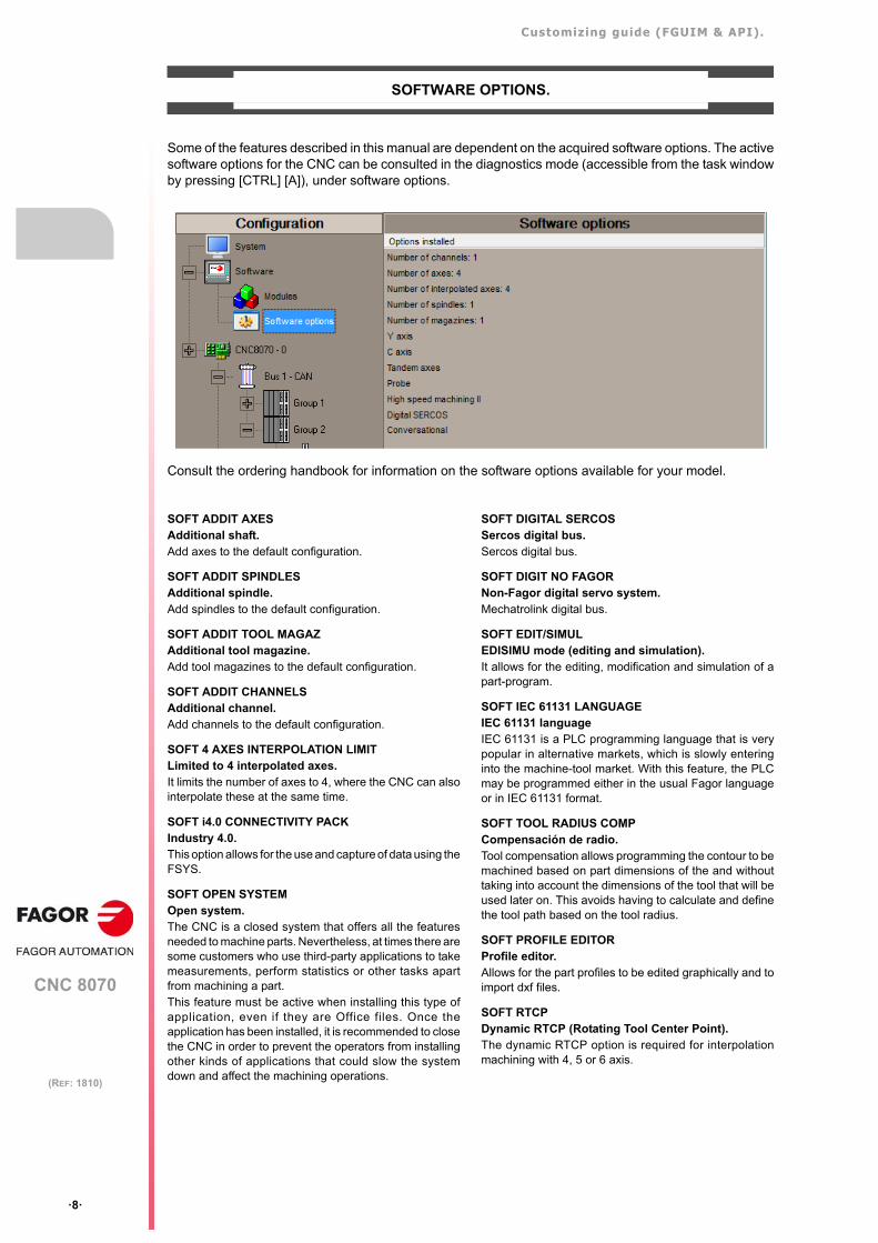
SOFTWARE OPTIONS.
Some of the features described in this manual are dependent on the acquired software options. The activesoftware options for the CNC can be consulted in the diagnostics mode (accessible from the task windowby pressing [CTRL] [A]), under software options.
Consult the ordering handbook for information on the software options available for your model.
SOFT ADDIT AXESAdditional shaft.Add axes to the default configuration.
SOFT ADDIT SPINDLESAdditional spindle.Add spindles to the default configuration.
SOFT ADDIT TOOL MAGAZAdditional tool magazine.Add tool magazines to the default configuration.
SOFT ADDIT CHANNELSAdditional channel.Add channels to the default configuration.
SOFT 4 AXES INTERPOLATION LIMITLimited to 4 interpolated axes.It limits the number of axes to 4, where the CNC can alsointerpolate these at the same time.
SOFT i4.0 CONNECTIVITY PACKIndustry 4.0.This option allows for the use and capture of data using theFSYS.
SOFT OPEN SYSTEMOpen system.The CNC is a closed system that offers all the featuresneeded to machine parts. Nevertheless, at times there aresome customers who use third-party applications to takemeasurements, perform statistics or other tasks apartfrom machining a part.This feature must be active when installing this type ofapplication, even if they are Office files. Once theapplication has been installed, it is recommended to closethe CNC in order to prevent the operators from installingother kinds of applications that could slow the systemdown and affect the machining operations.
SOFT DIGITAL SERCOSSercos digital bus.Sercos digital bus.
SOFT DIGIT NO FAGORNon-Fagor digital servo system.Mechatrolink digital bus.
SOFT EDIT/SIMULEDISIMU mode (editing and simulation).It allows for the editing, modification and simulation of apart-program.
SOFT IEC 61131 LANGUAGEIEC 61131 languageIEC 61131 is a PLC programming language that is verypopular in alternative markets, which is slowly enteringinto the machine-tool market. With this feature, the PLCmay be programmed either in the usual Fagor languageor in IEC 61131 format.
SOFT TOOL RADIUS COMPCompensación de radio.Tool compensation allows programming the contour to bemachined based on part dimensions of the and withouttaking into account the dimensions of the tool that will beused later on. This avoids having to calculate and definethe tool path based on the tool radius.
SOFT PROFILE EDITORProfile editor.Allows for the part profiles to be edited graphically and toimport dxf files.
SOFT RTCPDynamic RTCP (Rotating Tool Center Point).The dynamic RTCP option is required for interpolationmachining with 4, 5 or 6 axis.
Customizing guide (FGUIM & API).
CNC 8070
·9·
(REF: 1810)
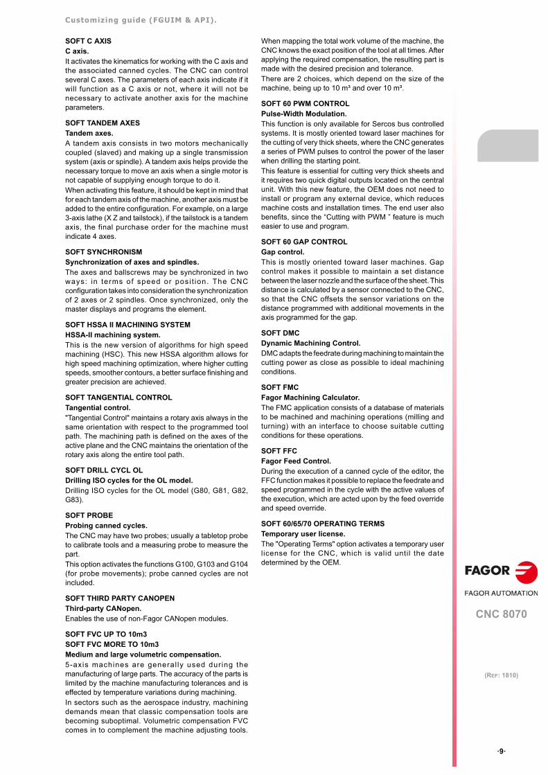
SOFT C AXISC axis.It activates the kinematics for working with the C axis andthe associated canned cycles. The CNC can controlseveral C axes. The parameters of each axis indicate if itwill function as a C axis or not, where it will not benecessary to activate another axis for the machineparameters.
SOFT TANDEM AXESTandem axes.A tandem axis consists in two motors mechanicallycoupled (slaved) and making up a single transmissionsystem (axis or spindle). A tandem axis helps provide thenecessary torque to move an axis when a single motor isnot capable of supplying enough torque to do it.When activating this feature, it should be kept in mind thatfor each tandem axis of the machine, another axis must beadded to the entire configuration. For example, on a large3-axis lathe (X Z and tailstock), if the tailstock is a tandemaxis, the final purchase order for the machine mustindicate 4 axes.
SOFT SYNCHRONISMSynchronization of axes and spindles.The axes and ballscrews may be synchronized in twoways: in terms of speed or posi t ion. The CNCconfiguration takes into consideration the synchronizationof 2 axes or 2 spindles. Once synchronized, only themaster displays and programs the element.
SOFT HSSA II MACHINING SYSTEMHSSA-II machining system.This is the new version of algorithms for high speedmachining (HSC). This new HSSA algorithm allows forhigh speed machining optimization, where higher cuttingspeeds, smoother contours, a better surface finishing andgreater precision are achieved.
SOFT TANGENTIAL CONTROLTangential control."Tangential Control" maintains a rotary axis always in thesame orientation with respect to the programmed toolpath. The machining path is defined on the axes of theactive plane and the CNC maintains the orientation of therotary axis along the entire tool path.
SOFT DRILL CYCL OLDrilling ISO cycles for the OL model.Drilling ISO cycles for the OL model (G80, G81, G82,G83).
SOFT PROBEProbing canned cycles.The CNC may have two probes; usually a tabletop probeto calibrate tools and a measuring probe to measure thepart. This option activates the functions G100, G103 and G104(for probe movements); probe canned cycles are notincluded.
SOFT THIRD PARTY CANOPENThird-party CANopen.Enables the use of non-Fagor CANopen modules.
SOFT FVC UP TO 10m3SOFT FVC MORE TO 10m3Medium and large volumetric compensation.5-axis machines are general ly used dur ing themanufacturing of large parts. The accuracy of the parts islimited by the machine manufacturing tolerances and iseffected by temperature variations during machining.In sectors such as the aerospace industry, machiningdemands mean that classic compensation tools arebecoming suboptimal. Volumetric compensation FVCcomes in to complement the machine adjusting tools.
When mapping the total work volume of the machine, theCNC knows the exact position of the tool at all times. Afterapplying the required compensation, the resulting part ismade with the desired precision and tolerance.There are 2 choices, which depend on the size of themachine, being up to 10 m³ and over 10 m³.
SOFT 60 PWM CONTROLPulse-Width Modulation.This function is only available for Sercos bus controlledsystems. It is mostly oriented toward laser machines forthe cutting of very thick sheets, where the CNC generatesa series of PWM pulses to control the power of the laserwhen drilling the starting point.This feature is essential for cutting very thick sheets andit requires two quick digital outputs located on the centralunit. With this new feature, the OEM does not need toinstall or program any external device, which reducesmachine costs and installation times. The end user alsobenefits, since the “Cutting with PWM ” feature is mucheasier to use and program.
SOFT 60 GAP CONTROLGap control.This is mostly oriented toward laser machines. Gapcontrol makes it possible to maintain a set distancebetween the laser nozzle and the surface of the sheet. Thisdistance is calculated by a sensor connected to the CNC,so that the CNC offsets the sensor variations on thedistance programmed with additional movements in theaxis programmed for the gap.
SOFT DMCDynamic Machining Control.DMC adapts the feedrate during machining to maintain thecutting power as close as possible to ideal machiningconditions.
SOFT FMCFagor Machining Calculator.The FMC application consists of a database of materialsto be machined and machining operations (milling andturning) with an interface to choose suitable cuttingconditions for these operations.
SOFT FFCFagor Feed Control.During the execution of a canned cycle of the editor, theFFC function makes it possible to replace the feedrate andspeed programmed in the cycle with the active values ofthe execution, which are acted upon by the feed overrideand speed override.
SOFT 60/65/70 OPERATING TERMSTemporary user license.The "Operating Terms" option activates a temporary userlicense for the CNC, which is valid until the datedetermined by the OEM.

BLANK PAGE
·10·
Customizing guide (FGUIM & API).
CNC 8070
·11·
(REF: 1810)
DECLARATION OF CE CONFORMITY AND WARRANTY CONDITIONS
DECLARATION OF CONFORMITY
The declaration of conformity for the CNC is available in the downloads section of FAGOR’S corporatewebsite. http://www.fagorautomation.com. (Type of file: Declaration of conformity).
WARRANTY TERMS
The warranty conditions for the CNC are available in the downloads section of FAGOR’s corporate website.http://www.fagorautomation.com. (Type of file: General sales-warranty conditions.

BLANK PAGE
·12·
Customizing guide (FGUIM & API).
CNC 8070
·13·
(REF: 1810)
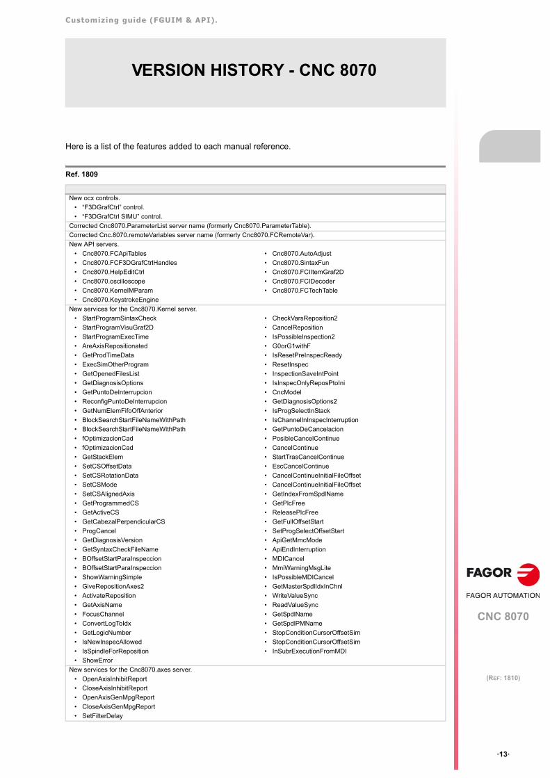
VERSION HISTORY - CNC 8070
Here is a list of the features added to each manual reference.
Ref. 1809
New ocx controls.
• “F3DGrafCtrl” control.
• “F3DGrafCtrl SIMU” control.
Corrected Cnc8070.ParameterList server name (formerly Cnc8070.ParameterTable).
Corrected Cnc.8070.remoteVariables server name (formerly Cnc8070.FCRemoteVar).
New API servers.
• Cnc8070.FCApiTables
• Cnc8070.FCF3DGrafCtrlHandles
• Cnc8070.HelpEditCtrl
• Cnc8070.oscilloscope
• Cnc8070.KernelMParam
• Cnc8070.KeystrokeEngine
• Cnc8070.AutoAdjust
• Cnc8070.SintaxFun
• Cnc8070.FCIItemGraf2D
• Cnc8070.FCIDecoder
• Cnc8070.FCTechTable
New services for the Cnc8070.Kernel server.
• StartProgramSintaxCheck
• StartProgramVisuGraf2D
• StartProgramExecTime
• AreAxisRepositionated
• GetProdTimeData
• ExecSimOtherProgram
• GetOpenedFilesList
• GetDiagnosisOptions
• GetPuntoDeInterrupcion
• ReconfigPuntoDeInterrupcion
• GetNumElemFifoOffAnterior
• BlockSearchStartFileNameWithPath
• BlockSearchStartFileNameWithPath
• fOptimizacionCad
• fOptimizacionCad
• GetStackElem
• SetCSOffsetData
• SetCSRotationData
• SetCSMode
• SetCSAlignedAxis
• GetProgrammedCS
• GetActiveCS
• GetCabezalPerpendicularCS
• ProgCancel
• GetDiagnosisVersion
• GetSyntaxCheckFileName
• BOffsetStartParaInspeccion
• BOffsetStartParaInspeccion
• ShowWarningSimple
• GiveRepositionAxes2
• ActivateReposition
• GetAxisName
• FocusChannel
• ConvertLogToIdx
• GetLogicNumber
• IsNewInspecAllowed
• IsSpindleForReposition
• ShowError
• CheckVarsReposition2
• CancelReposition
• IsPossibleInspection2
• G0orG1withF
• IsResetPreInspecReady
• ResetInspec
• InspectionSaveIntPoint
• IsInspecOnlyReposPtoIni
• CncModel
• GetDiagnosisOptions2
• IsProgSelectInStack
• IsChannelInInspecInterruption
• GetPuntoDeCancelacion
• PosibleCancelContinue
• CancelContinue
• StartTrasCancelContinue
• EscCancelContinue
• CancelContinueInitialFileOffset
• CancelContinueInitialFileOffset
• GetIndexFromSpdlName
• GetPlcFree
• ReleasePlcFree
• GetFullOffsetStart
• SetProgSelectOffsetStart
• ApiGetMmcMode
• ApiEndInterruption
• MDICancel
• MmiWarningMsgLite
• IsPossibleMDICancel
• GetMasterSpdlIdxInChnl
• WriteValueSync
• ReadValueSync
• GetSpdlName
• GetSpdlPMName
• StopConditionCursorOffsetSim
• StopConditionCursorOffsetSim
• InSubrExecutionFromMDI
New services for the Cnc8070.axes server.
• OpenAxisInhibitReport
• CloseAxisInhibitReport
• OpenAxisGenMpgReport
• CloseAxisGenMpgReport
• SetFilterDelay
Customizing guide (FGUIM & API).
CNC 8070
·14·
(REF: 1810)
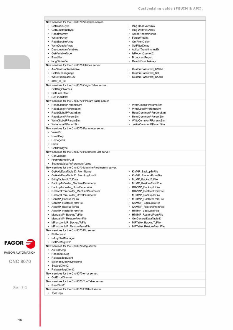
New services for the Cnc8070.Variables server.
• GetStatusByte
• GetSubstatusByte
• ReadIntArray
• WriteIntArray
• ReadDoubleArray
• WriteDoubleArray
• DesconectarVariables
• GetVariableType
• ReadVar
• long WriteVar
• long ReadVarArray
• long WriteVarArray
• AplicarTransfInches
• ForceWriteInt
• GetFilterDelay
• SetFilterDelay
• AplicarTransfInchesEx
• IsReportOpened2
• BroadcastReport
• ReadNDoubleArray
New services for the Cnc8070.Utilities server.
• AreNewGraphicsActive
• Get8070Language
• WriteTxtInBlackBox
• error_to_txt
• CustomPassword_IsValid
• CustomPassword_Set
• CustomPassword_Check
New services for the Cnc8070.Origin Table server.
• GetOriginNames
• GetFineOffset
• SetFineOffset
New services for the Cnc8070.PParam Table server.
• ReadGlobalPParamsSim
• ReadLocalPParamsSim
• ReadGlobalPParamSim
• ReadLocalPParamSim
• WriteGlobalPParamSim
• WriteLocalPParamSim
• WriteGlobalPParamsSim
• WriteLocalPParamsSim
• ReadCommonPParamsSim
• ReadCommonPParamSim
• WriteCommonPParamsSim
• WriteCommonPParamSim
New services for the Cnc8070.Parameter server.
• ValueEx
• ReadOnly
• Homogeniz
• Show
• GetDataType
New services for the Cnc8070.Parameter List server.
• CanValidate
• FirstParameterCol
• SetInputValueAsParameterValue
New services for the Cnc8070.MachineParameters server.
• GetAxisDataTableID_FromName
• GetAxisDataTableID_FromLogAxisNr
• BringTablesUpToDate
• BackupToFolder_MachineParameter
• BackupToFolder_DriveParameter
• RestoreFromFolder_MachineParameter
• RestoreFromFolder_DriveParameter
• GenMP_BackupToFile
• GenMP_RestoreFromFile
• AxisMP_BackupToFile
• AxisMP_RestoreFromFile
• ManualMP_BackupToFile
• ManualMP_RestoreFromFile
• MFunctionMP_BackupToFile
• MFunctionMP_RestoreFromFile
• KinMP_BackupToFile
• KinMP_RestoreFromFile
• MzMP_BackupToFile
• MzMP_RestoreFromFile
• DRVMP_BackupToFile
• DRVMP_RestoreFromFile
• MTBMP_BackupToFile
• MTBMP_RestoreFromFile
• CAMMP_BackupToFile
• CAMMP_RestoreFromFile
• HMIMP_BackupToFile
• HMIMP_RestoreFromFile
• GetGeneralDataTableID
• MPTable_BackupToFile
• MPTable_RestoreFromFile
New services for the Cnc8070.Plc server.
• PlcRequest
• IsAnyStartManager
• GetPlcMsgList2
New services for the Cnc8070.Jog server.
• ActivateJog
• ResetStateJog
• ReleaseJogClient
• ExtendedJogKeyReports
• SetJogClient2
• ReleaseJogClient2
New services for the Cnc8070.error server.
• GetErrorChannel
New services for the Cnc8070.ToolTable server
• ReadTool2
New services for the Cnc8070.FCITool server.
• ToolCopy
Customizing guide (FGUIM & API).
CNC 8070
·15·
(REF: 1810)
New services for the Cnc8070.FCIEdge server.
• WarningLife
• AddOffset
• DeleteOffset
• EdgeCopy
New services for the Cnc8070.MagazineTable server.
• DeleteToolSim
• ActualizeTDActive
New services for the Cnc8070.FCIPlaceStorage server.
• IsFreeLeft
• IsFreeRight
• IsLoaded
• IsLoadedLeft
• IsLoadedRight
• GetToolID
New services for the Cnc8070.remoteVariables server.
• ReadVarArray
• WriteVarArray
• IsWritable
New services for the Cnc8070.GrafData server.
• ToolLocationCode
• ToolLc
• ToolFixori
• AxisPlane3
• TipoGraf
• TornoXZ
• ToolTyp
• ToolSubTyp
• PasoG33
• EjeG33
• PieceInDGWZ
• ToolType
• SpindlePosIncrement
• SpindlePosReal
• SpindlePosTheoretic
• VelocidadGrafSimu
• ActiveKinId
• SpindleLogNumber
• IsBallbarActive
• ActivateBallbar
• DeactivateBallbar
• ActualizeBallbar
• AxisRealMachineValue
• AxisTheoreticMachineValue
• IsNuevaG33
• DisconnectNotify
• AxisRealMachineBaseValue
• AxisTheoreticMachineBaseValue
• IsKinematicChange
• GetAxisLog
• IsChannelInDGWZ
• GetLogAxis
• IsNewInfo
• GetLazoCount
• Actualize2
• IsProgramStarted
• ActivateGraf
• ActivateGrafSimu
• DeactivateGraf
• DeactivateGrafSimu
• IsSpdlStatusChange
• GetSpdlStatus
• GetSpdlSpeed
• IsStateChange
• IsForcedOutput
• IsNewMachine
• GetMachineFile
• GetOffset
• GetPieceType
• GetPieceAxis
• IsSyncBlock
• GetSyncCommand
• GetSyncMark
• GetSyncChannels
• SetSimuAccuracy
New notifications for the Api8070.
• Function warning about the status change of an axis (cnc8070.Axes).AxisEnableReport
• Function warning about the status change for an axis with a report inhibit (Cnc8070.Axes).AxisInhibitReport
• Function warning of a status change for an axis with a GenMpg report (Cnc8070.Axes).AxisGenMpgReport
• CYSTART warning function (Cnc8070.Plc).CYStartReport
• CYSTART warning function (Cnc8070.Plc).CYStartChannelReport
• Function warning of a change in a “P” parameter (Cnc8070.PparamTable)
• PParamReport
• Key press warning function (Cnc8070.Jog).KeyReport
• Key press warning function (Cnc8070.Jog).KeyReport2
• Oscilloscope status change warning function (Cnc8070.AutoAdjust).Report
• Bode status change warning function (Cnc8070.AutoAdjust).AutoAdjustBodeStatusReport

BLANK PAGE
·16·
Customizing guide (FGUIM & API).
CNC 8070
·17·
(REF: 1810)
SAFETY CONDITIONS
Read the following safety measures in order to prevent harming people or damage to this product and thoseproducts connected to it. Fagor Automation shall not be held responsible of any physical or material damageoriginated from not complying with these basic safety rules.
PRECAUTIONS BEFORE CLEANING THE UNIT
PRECAUTIONS DURING REPAIRS
In case of a malfunction or failure, disconnect it and call the technical service.
PRECAUTIONS AGAINST PERSONAL HARM
Before start-up, verify that the machine that integrates this CNC meets the 2006/42/EC Directive.
Do not get into the inside of the unit. Only personnel authorized by Fagor Automation may access theinterior of this unit.
Do not handle the connectors with the unitconnected to AC power.
Before handling these connectors (I/O, feedback, etc.), make surethat the unit is not powered.
Do not get into the inside of the unit. Only personnel authorized by Fagor Automation may access theinterior of this unit.
Do not handle the connectors with the unitconnected to AC power.
Before handling these connectors (I/O, feedback, etc.), make surethat the unit is not powered.
Interconnection of modules. Use the connection cables provided with the unit.
Use proper cables. To prevent risks, only use cables and Sercos fiber recommended forthis unit. To prevent a risk of electrical shock at the central unit, use the properconnector (supplied by Fagor); use a three-prong power cable (oneof them being ground).
Avoid electric shocks. To prevent electrical shock and fire risk, do not apply electrical voltageout of the indicated range.
Ground connection. In order to avoid electrical discharges, connect the ground terminalsof all the modules to the main ground terminal. Also, beforeconnecting the inputs and outputs of this product, make sure that theground connection has been done.In order to avoid electrical shock, before turning the unit on verify thatthe ground connection is properly made.
Do not work in humid environments. In order to avoid electrical discharges, always work with a relativehumidity (non-condensing).
Do not work in explosive environments. In order to avoid risks, harm or damages, do not work in explosiveenvironments.
Customizing guide (FGUIM & API).
CNC 8070
·18·
(REF: 1810)
PRECAUTIONS AGAINST DAMAGE TO THE PRODUCT
SAFETY SYMBOLS
Symbols that may appear in the manual.
Work environment. This unit is ready to be used in industrial environments complying withthe directives and regulations effective in the European Community.Fagor Automation shall not be held responsible for any damagesuffered or caused by the CNC when installed in other environments(residential, homes, etc.).
Install this unit in the proper place. It is recommended, whenever possible, to install the CNC away fromcoolants, chemical product, blows, etc. that could damage it.This unit meets the European directives on electromagneticcompatibility. Nevertheless, it is recommended to keep it away fromsources of electromagnetic disturbance such as:
Powerful loads connected to the same mains as the unit.Nearby portable transmitters (radio-telephones, Ham radiotransmitters).Nearby radio / TC transmitters.Nearby arc welding machines.Nearby high voltage lines.
Enclosures. It is up to the manufacturer to guarantee that the enclosure where theunit has been installed meets all the relevant directives of theEuropean Union.
Avoid disturbances coming from themachine.
The machine must have all the interference generating elements(relay coils, contactors, motors, etc.) uncoupled.
Use the proper power supply. Use an external regulated 24 Vdc power supply for the keyboard,operator panel and the remote modules.
Connecting the power supply to ground. The zero Volt point of the external power supply must be connectedto the main ground point of the machine.
Analog inputs and outputs connection. Use shielded cables connecting all their meshes to the correspondingpin.
Ambient conditions. Maintain the CNC within the recommended temperature range, bothwhen running and not running. See the corresponding chapter in thehardware manual.
Central unit enclosure. To maintain the right ambient conditions in the enclosure of the centralunit, it must meet the requirements indicated by Fagor. See thecorresponding chapter in the hardware manual.
Power switch. This switch must be easy to access and at a distance between 0.7 and1.7 m (2.3 and 5.6 ft) off the floor.
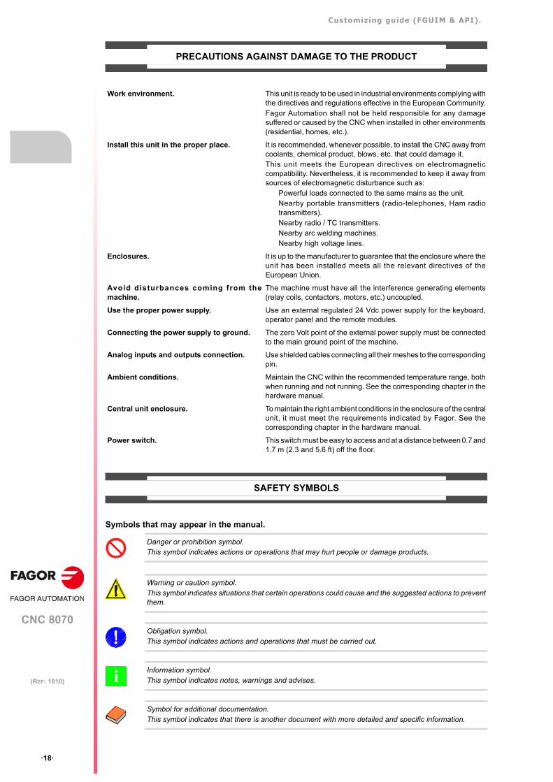
Danger or prohibition symbol.This symbol indicates actions or operations that may hurt people or damage products.
Warning or caution symbol.This symbol indicates situations that certain operations could cause and the suggested actions to preventthem.
Obligation symbol. This symbol indicates actions and operations that must be carried out.
Information symbol.This symbol indicates notes, warnings and advises.
Symbol for additional documentation.This symbol indicates that there is another document with more detailed and specific information.
i

Customizing guide (FGUIM & API).
CNC 8070
·19·
(REF: 1810)
Symbols that the product may carry.
Ground symbol.This symbol indicates that that point must be under voltage.
ESD components.This symbol identifies the cards as ESD components (sensitive to electrostatic discharges).

BLANK PAGE
·20·
Customizing guide (FGUIM & API).
CNC 8070
·21·
(REF: 1810)
RETURNING CONDITIONS
Pack it in its original package along with its original packaging material. If you do not have the originalpackaging material, pack it as follows:
1 Get a cardboard box whose 3 inside dimensions are at least 15 cm (6 inches) larger than those of theunit itself. The cardboard being used to make the box must have a resistance of 170 Kg (375 lb.).
2 Attach a label to the device indicating the owner of the device along with contact information (address,telephone number, email, name of the person to contact, type of device, serial number, etc.). In caseof malfunction also indicate symptom and a brief description of the problem.
3 Protect the unit wrapping it up with a roll of polyethylene or with similar material. When sending a centralunit with monitor, protect especially the screen.
4 Pad the unit inside the cardboard box with polyurethane foam on all sides.
5 Seal the cardboard box with packaging tape or with industrial staples.

BLANK PAGE
·22·
Customizing guide (FGUIM & API).
CNC 8070
·23·
(REF: 1810)
CNC MAINTENANCE
CLEANING
The accumulated dirt inside the unit may act as a screen preventing the proper dissipation of the heatgenerated by the internal circuitry which could result in a harmful overheating of the unit and, consequently,possible malfunctions. Accumulated dirt can sometimes act as an electrical conductor and short-circuit theinternal circuitry, especially under high humidity conditions.
To clean the operator panel and the monitor, a smooth cloth should be used which has been dipped intode-ionized water and /or non abrasive dish-washer soap (liquid, never powder) or 75º alcohol. Never useair compressed at high pressure to clean the unit because it could cause the accumulation of electrostaticcharges that could result in electrostatic shocks.
The plastics used on the front panel are resistant to grease and mineral oils, bases and bleach, dissolveddetergents and alcohol. Avoid the action of solvents such as chlorine hydrocarbons, venzole, esters andether which can damage the plastics used to make the unit’s front panel.
PRECAUTIONS BEFORE CLEANING THE UNIT
Fagor Automation shall not be held responsible for any material or physical damage derived from theviolation of these basic safety requirements.
• Do not handle the connectors with the unit supplied with power. Before handling these connectors (I/O,feedback, etc.), make sure that the unit is not powered.
• Do not get into the inside of the unit. Only personnel authorized by Fagor Automation may access theinterior of this unit.

BLANK PAGE
·24·
CNC 8070
1
·25·
(REF: 1810)
1. BEFORE STARTING.
The purpose of this manual is to be used as a guide to customize the work environment ofthe CNC which may be easily customized using the application FGUIM (which is installedtogether with the CNC) or more deeply using scripts or API.
FGUIM.
FGUIM is an application for personalizing the work environment of the CNC. Thisenvironment is organized with a number of components that represent the CNC's variouswork modes.
Using the FGUIM, these components may be designed graphically and easily. To design thepages (screens) of certain components, it offers a library of controls specifically dedicatedto the CNC. However, it is also possible to easily add any additional control.
Scripts.
The scripts are an extended functionality of the FGUIM that make it possible to provide thecontrols with the possibility to govern certain functions of the CNC.
Screen customizing without scripts.
This type of customization permits the modification of the operation of the Fagor and usercomponents without having to need to use scripting languages. The operation of a page isdefined by its properties and indicating the actions that are executed when a particularcondition is met; press a softkey, press a page button (Button or Multistatic control) or whenthe page meets a condition (for example, when a variable takes on a value).
API8070.
The API is a library for the development of applications that will communicate with the CNC.The library offers a number of objects (COM) that in turn export some functions which arethe ones that actually communicate with the kernel of the CNC.
Unlike the FGUIM, the API is not based on the standard work environment of the CNC. TheCNC interface may be designed using any application and the API may be used toestablished communication between the new interface and the CNC.
Customizing guide (FGUIM & API).
CNC 8070
1.
BE
FO
RE
ST
AR
TIN
G.
Man
ual
con
ten
ts.
·26·
(REF: 1810)
1.1 Manual contents.
This manual comprises the following chapters. They contain the necessary information topersonalize the CNC and a complete reference of the functions to programming using scriptsor the API.
"Before starting."
This chapter is meant to be a reference of the information that may befound in this manual.
"General description of the FGUIM."
This chapter is an introductory guide to the FGUIM that describes its basicfunctions. It also offers a description of the elements that make up the workenvironment of the FGUIM, such as tool bars, menus, etc.
"MMC8070 and standard components."
This chapter shows how to personalize the standard components.
"Configurable components"
This chapter explains how to create user components.
"Configurable components List of controls."
This chapter shows the available controls and their properties.
"Configurable components Screen customizing without scripts."
This chapter describes how to set the browsing between components andbetween pages, as well as their operation, without using scripts.
"Examples of customizing without scripts."
Several examples to create user components and cycles.
"Configurable components. scripts."
This chapter describes how to access the script editor and how to definedthem; for that, it offers a complete list of methods and events that may beused with each available server. This chapter also describes how to createa resource library.
"API8070."
This chapter describes how to use the API8070 and it also offers acomplete list of the functions of each available server.
1
2
3
4
5
6
7
8
9
Customizing guide (FGUIM & API).
CNC 8070
BE
FO
RE
ST
AR
TIN
G.
1.
Con
ven
tions
use
d in
this
man
ual
.
·27·
(REF: 1810)
1.2 Conventions used in this manual.
There is little to say about how the subjects will be described. However, the following shouldbe borne in mind:
• The numbered paragraphed (except for the titles) must be followed sequentially, step bystep. Do not go to a point until completing the previous one.
• The bulleted paragraphs, like this one, correspond either to instructions that may becarried out without following any particular order or sequence or correspond to a bunchof possibilities.
• Paragraphs that are identified with letters refer to parts of a drawing or diagram.
• The menu commands appear in italic, for example: "Edit".
Using the keyboard.
• The names of the keys appear in brackets, for example: [CTRL].
Using the mouse.
• When mentioning to click a mouse button, it means to place the cursor on the elementand press and release the indicated mouse button.
• When mentioning double-clicking with a mouse button, this means placing the cursorover an element and pressing and releasing the indicated button twice.
• [CTRL]+[M] The keystroke combinations appear separated by a "+", for example:[CTRL]+[M]. This means that the [CTRL] and [M] keys must be pressedat the same time.
• [ALT],[W] Key sequences are separated by a comma, for example [ALT], [W]. Thismeans that you must press and release the [ALT] key and then the [W] key.

Customizing guide (FGUIM & API).
CNC 8070
1.
BE
FO
RE
ST
AR
TIN
G.
Con
ven
tions
use
d in
this
man
ual
.
·28·
(REF: 1810)
CNC 8070
2
·29·
(REF: 1810)
2. GENERAL DESCRIPTION OF THE FGUIM.
Starting the FGUIM.
FGUIM is an application external to the CNC; i.e. it is not executed from the CNC. To executeFGUIM, click twice with the mouse on the "FGUIM" icon created on the desk by theinstallation program.
Exiting FGUIM.
To exit FGUIM, select the "Exit" option of the "File" menu. If the changes have not beenpreviously saved, it will ask whether it is to be saved or not.
Saving the changes made with the FGUIM.
The configuration defined may be saved through the "Save" and "Save as..." options of the"File" menu. These options are only available when the configuration has been changed.
• The "Save" option saves the configuration in its corresponding directory. It replaces theprevious configuration.
• The "Save as..." option may be used to select the directory where the configuration willbe saved. However, when starting FGUIM, it always loads the configuration saved in thedirectory ..\MTB\MMC.
Where is the configuration saved?
The elements of the configuration are saved in the following directories of the root directory:
• ..\MTB\MMC
Configuration files (ini) associated with the components.
• ..\MTB\MMC\Config
Information associated with the components and controls.
• ..\MTB\MMC\Images
Files such as bitmaps, videos, icons, etc.
• ..\Release
Controls (OCX files) that the user wants to add to the FGUIM.
Updating the components at the CNC.
Once a component has been designed or modified, it is updated at the CNC the next timeit is turned on. For the changes to be assumed at the CNC, they must be previously savedfrom the FGUIM.
Customizing guide (FGUIM & API).
CNC 8070
2.
GE
NE
RA
L D
ES
CR
IPT
ION
OF
TH
E F
GU
IM.
Wor
k en
viro
nmen
t. In
terf
ace
desc
riptio
n.
·30·
(REF: 1810)
2.1 Work environment. Interface description.
The work environment is shown as soon as the FGUIM is started up. The FGUIM has anintelligent interface that only shows the valid options for selected component. It hides therest of the elements.
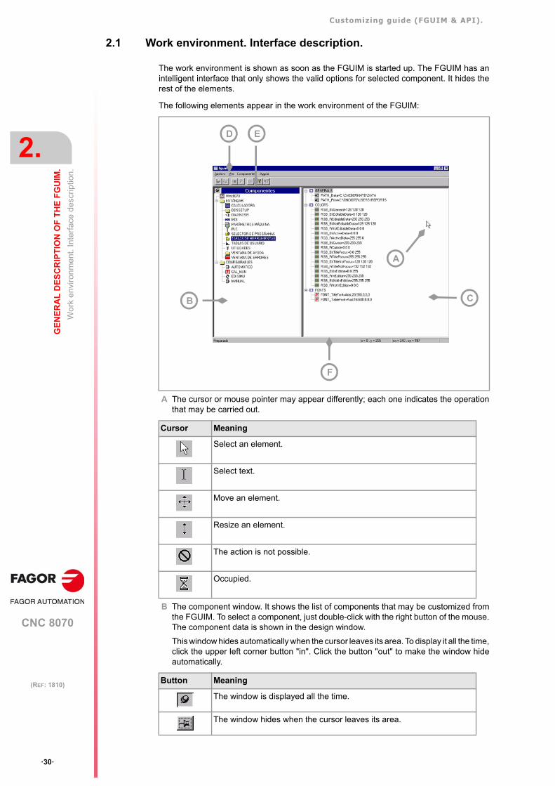
The following elements appear in the work environment of the FGUIM:
A The cursor or mouse pointer may appear differently; each one indicates the operationthat may be carried out.
B The component window. It shows the list of components that may be customized fromthe FGUIM. To select a component, just double-click with the right button of the mouse.The component data is shown in the design window.
This window hides automatically when the cursor leaves its area. To display it all the time,click the upper left corner button "in". Click the button "out" to make the window hideautomatically.
Cursor Meaning
Select an element.
Select text.
Move an element.
Resize an element.
The action is not possible.
Occupied.
Button Meaning
The window is displayed all the time.
The window hides when the cursor leaves its area.
F
A
C
ED
B
Customizing guide (FGUIM & API).
CNC 8070
GE
NE
RA
L D
ES
CR
IPT
ION
OF
TH
E F
GU
IM.
2.
Wor
k en
viro
nmen
t. In
terf
ace
desc
riptio
n.
·31·
(REF: 1810)
C The design window is the area reserved to customize the components. It shows theinformation associated with the element selected on the component window.
D The menu bar is the upper area of the screen. The menus are expanded by clicking theleft button on the mouse. To select one of its options proceed the same way. See "2.3 Themenu bar." on page 33.
E The tool bars include buttons to execute commands or carry out operations with theelement currently selected. It is possible to move, show and hide the task bars. See"2.2 The tool bars." on page 32.
Leaving the cursor on a button, the status bar shows a description of that button'sfunction.
F The status bar, at the bottom of the screen, shows information of several parameters ofthe drawing, such as the cursor position or the size of the selected element.
G Dialog boxes are windows that are displayed in the center of the screen. They may beused to select customizing options. See "2.4 The dialog boxes." on page 34.
Customizing guide (FGUIM & API).
CNC 8070
2.
GE
NE
RA
L D
ES
CR
IPT
ION
OF
TH
E F
GU
IM.
Th
e to
ol b
ars.
·32·
(REF: 1810)
2.2 The tool bars.
FGUIM offers the following tool bars:
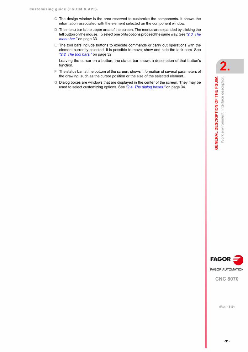
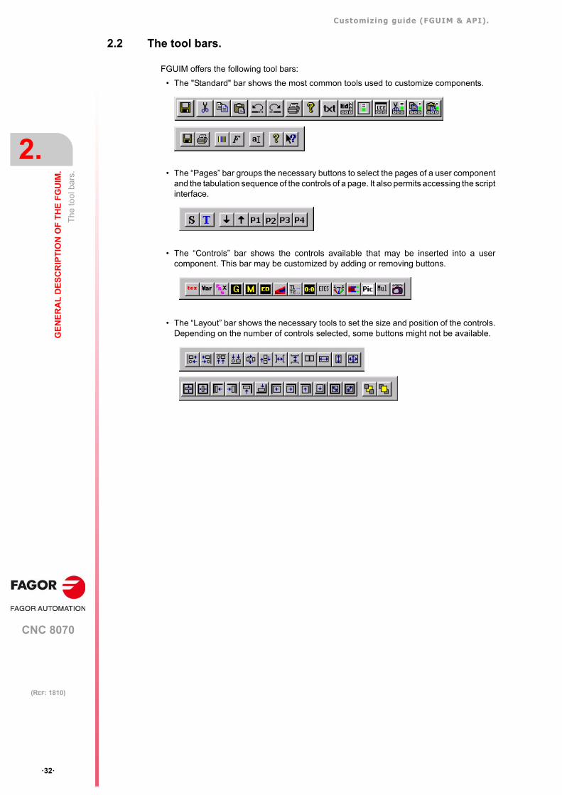
• The "Standard" bar shows the most common tools used to customize components.
• The “Pages” bar groups the necessary buttons to select the pages of a user componentand the tabulation sequence of the controls of a page. It also permits accessing the scriptinterface.
• The “Controls” bar shows the controls available that may be inserted into a usercomponent. This bar may be customized by adding or removing buttons.
• The “Layout” bar shows the necessary tools to set the size and position of the controls.Depending on the number of controls selected, some buttons might not be available.
Customizing guide (FGUIM & API).
CNC 8070
GE
NE
RA
L D
ES
CR
IPT
ION
OF
TH
E F
GU
IM.
2.
The
men
u ba
r.
·33·
(REF: 1810)
2.3 The menu bar.
–File– menu
This menu may be used to save the changes made to the components, insert / removecontrols in / from the "Controls" bar and finish with the FGUIM.
–Edit– menu
This menu groups the basic editing options.
–Page– menu
This menu groups the necessary tools to work with the pages of a user component.
–View– menu
From this menu, it is possible to show or hide the tool bars. It also accesses the propertiesof a control and shows their tabulation sequence.
–Components– menu
This menu permits adding or removing user components.
–Script– menu
This menu groups all the necessary options to program scripts.
–Help– menu
Help options of the FGUIM.
Customizing guide (FGUIM & API).
CNC 8070
2.
GE
NE
RA
L D
ES
CR
IPT
ION
OF
TH
E F
GU
IM.
The
dia
log
box
es.
·34·
(REF: 1810)
2.4 The dialog boxes.
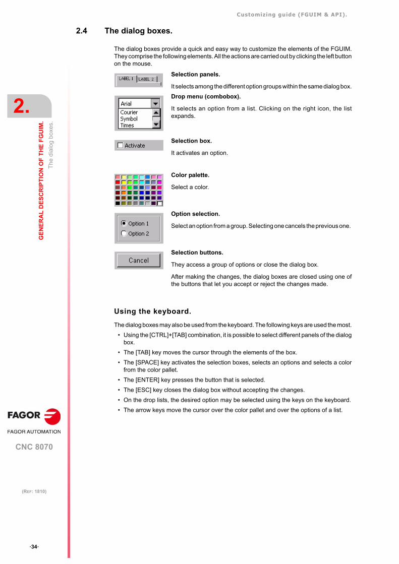
The dialog boxes provide a quick and easy way to customize the elements of the FGUIM.They comprise the following elements. All the actions are carried out by clicking the left buttonon the mouse.
Using the keyboard.
The dialog boxes may also be used from the keyboard. The following keys are used the most.
• Using the [CTRL]+[TAB] combination, it is possible to select different panels of the dialogbox.
• The [TAB] key moves the cursor through the elements of the box.
• The [SPACE] key activates the selection boxes, selects an options and selects a colorfrom the color pallet.
• The [ENTER] key presses the button that is selected.
• The [ESC] key closes the dialog box without accepting the changes.
• On the drop lists, the desired option may be selected using the keys on the keyboard.
• The arrow keys move the cursor over the color pallet and over the options of a list.
Selection panels.
It selects among the different option groups within the same dialog box.
Drop menu (combobox).
It selects an option from a list. Clicking on the right icon, the listexpands.
Selection box.
It activates an option.
Color palette.
Select a color.
Option selection.
Select an option from a group. Selecting one cancels the previous one.
Selection buttons.
They access a group of options or close the dialog box.
After making the changes, the dialog boxes are closed using one ofthe buttons that let you accept or reject the changes made.
CNC 8070
3
·35·
(REF: 1810)
3. MMC8070 AND STANDARD COMPONENTS.
3.1 Design of the MMC8070 and the standard components.
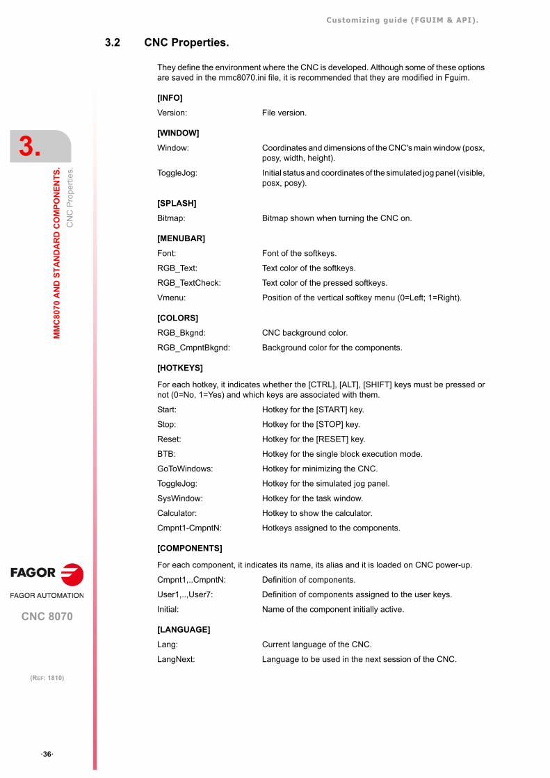
When selecting a standard component, a list of configurable properties appears on thescreen. The properties appear grouped in sections, each one corresponds with the one inthe component's configuration file (ini). The properties are of three types:
It is possible to edit the type of font or the color in text mode. This may be done using the"Text" option of the "Edit" menu or its corresponding button.
If any property of the font or color type is not automatically recognized by the FGUIM, it maybe because its name does not start with "font" or "RGB". To edit these properties with theircorresponding dialog boxes, select the "Font" or "Color" option of the "Editar" menu.
Font: When selecting this property, the screen shows the dialog box forselecting the type of font. The font will be assigned to the propertyautomatically.
Color: When selecting this property, the screen shows the dialog box forselecting the color. The selected color will be assigned to the propertyautomatically.
Texto: When selecting this property, the value of the property may be writtendirectly.
Customizing guide (FGUIM & API).
CNC 8070
3.
MM
C80
70
AN
D S
TA
ND
AR
D C
OM
PO
NE
NT
S.
CN
C P
rope
rtie
s.
·36·
(REF: 1810)
3.2 CNC Properties.
They define the environment where the CNC is developed. Although some of these optionsare saved in the mmc8070.ini file, it is recommended that they are modified in Fguim.
[INFO]
Version: File version.
[WINDOW]
Window: Coordinates and dimensions of the CNC's main window (posx,posy, width, height).
ToggleJog: Initial status and coordinates of the simulated jog panel (visible,posx, posy).
[SPLASH]
Bitmap: Bitmap shown when turning the CNC on.
[MENUBAR]
Font: Font of the softkeys.
RGB_Text: Text color of the softkeys.
RGB_TextCheck: Text color of the pressed softkeys.
Vmenu: Position of the vertical softkey menu (0=Left; 1=Right).
[COLORS]
RGB_Bkgnd: CNC background color.
RGB_CmpntBkgnd: Background color for the components.
[HOTKEYS]
For each hotkey, it indicates whether the [CTRL], [ALT], [SHIFT] keys must be pressed ornot (0=No, 1=Yes) and which keys are associated with them.
Start: Hotkey for the [START] key.
Stop: Hotkey for the [STOP] key.
Reset: Hotkey for the [RESET] key.
BTB: Hotkey for the single block execution mode.
GoToWindows: Hotkey for minimizing the CNC.
ToggleJog: Hotkey for the simulated jog panel.
SysWindow: Hotkey for the task window.
Calculator: Hotkey to show the calculator.
Cmpnt1-CmpntN: Hotkeys assigned to the components.
[COMPONENTS]
For each component, it indicates its name, its alias and it is loaded on CNC power-up.
Cmpnt1,..CmpntN: Definition of components.
User1,..,User7: Definition of components assigned to the user keys.
Initial: Name of the component initially active.
[LANGUAGE]
Lang: Current language of the CNC.
LangNext: Language to be used in the next session of the CNC.
Customizing guide (FGUIM & API).
CNC 8070
MM
C80
70
AN
D S
TA
ND
AR
D C
OM
PO
NE
NT
S.
3.
CN
C P
rope
rtie
s.
·37·
(REF: 1810)
[TIMERS]
BaseRefreshRate: Base time (in ms) to refresh the controls with an external timer.
FastDivRate: Dividing factor of the base time.
MediumxRate: Multiplying factor of the base time.
LowxRate: Multiplying factor of the base time.
[SYSWIND]
Properties of the tasks window
Timer: Time it takes the tasks window to close automatically (in ms).If "0", it does not close.
RGB_Bkgnd: Background color of the tasks window.
RGB_Text: Text color of the tasks window.
Position: Display coordinates of the tasks window.
RGB_BkgndFocus: Background color of the tasks window (Focus).
RGB_TextFocus: Text color of the tasks window (Focus).
[STATUS]
Properties of the status bar.
Bitmap: OEM's bitmap.
RGB_NoReady: Color when the status is Not Ready.
RGB_Ready: Color when the status is Ready.
RGB_Running: Color when the status is Running.
RGB_Interrupted: Color when the status is Interrupted.
RGB_InterruptedByError: Color when the status is Interrupted by error.
Font_Filename: The font type used to show the name of the program selectedfor execution.
[EXIT]
ExitWindows: Quit Windows when closing the CNC ("0"=No / "1"=Yes).
[FORMAT]
FFormat: Format to represent feedrate (integers.decimals).
SFormat: Format to represent speed (integers.decimals).
[OPTION]
8055ANALYZER: Syntax analyzer of the language of the 8055 CNC.
STARTONBACKGROUND: Minimized CNC start-up.
BACKGROUNDMODE: Keep the interface minimized, even after a warning or an error,when pressing the mode keys, etc. The interface comes to theforeground only after a system error or by pressing[CTRL]+[W].
Customizing guide (FGUIM & API).
CNC 8070
3.
MM
C80
70
AN
D S
TA
ND
AR
D C
OM
PO
NE
NT
S.
Pro
pert
ies
of s
tand
ard
com
pon
ents
·38·
(REF: 1810)
3.3 Properties of standard components
"Calculator" component.
[COMMON]
Window: Coordinates and dimensions of the calculator.
"DDSSETUP" component.
[COMMON]
lang: language file.
[ANALOG CHANNEL]
Analog channel configuration.
[DIGITAL CHANNEL]
Digital channel configuration.
[TRIGGER]
Trigger condition configuration.
[OSCILLOSCOPE]
Configuration of the oscilloscope.
[BACKUP-RESTORE]
Default folder for backup-restore.
"DIAGNOSIS" component.
[GENERAL]
PATH_Print: Path where the data printed out to a file is saved.
"TOOLS" component.
[GENERAL]
FirstTimeCNCUsed: For internal use.
SecurityBackup: For internal use.
PATH_Data: Path where the data is saved.
PATH_Print: Path where the data printed out to a file is saved.
[COLORS]
RGB_BkGeneral: General background color.
RGB_BkEditableData: Background color for fields that may be edited.
RGB_FrEditableData: Text color for fields that may be edited.
RGB_BkNotEditableData: Background color for fields that cannot be edited.
RGB_FrNotEditableData: Text color for fields that cannot be edited.
RGB_BkActiveData: Background color of the active data.
RGB_FrActiveData: Text color of the active data.
RGB_BkCursor: Background color of the cursor in parameter tables.
RGB_FrCursor: Text color of the cursor in parameter tables.
RGB_BkTitleFocus: Background color for the title of tables with focus.
Customizing guide (FGUIM & API).
CNC 8070
MM
C80
70
AN
D S
TA
ND
AR
D C
OM
PO
NE
NT
S.
3.
Pro
pert
ies
of s
tand
ard
com
pon
ents
·39·
(REF: 1810)
RGB_FrTitleFocus: Text color for the title of tables with focus.
RGB_BkTitleNotFocus: Background color for the title of tables without focus.
RGB_FrTitleNotFocus: Text color for the title of tables without focus.
RGB_BkInEdition: Background color for editing controls.
RGB_FrInEdition: Text color for editing controls.
RGB_BkNotInEdition: Background color for non-editing controls.
RGB_FrNotInEdition: Text color for non-editing controls.
[FONTS]
FONT_TitleFont: Title font.
FONT_TableFont: Table font.
"MDI" component.
[COMMON]
RGB_Bkgnd: Background color of the border.
[PRIVATE]
RGB_Bkgnd: Background color of the editing area.
RGB_Text: Text color.
RGB_BkgndRunnig: Background color of the editing area when executing an MDIcommand.
RGB_TextRunnig: Text color when executing an MDI command.
Font: Text font.
Nitems: Number of MDI commands stored.
Item1,..,itemN: MDI commands.
Dir: Folder for the option of saving the blocks as a file.
"MACHINE PARAMETERS" component.
[GENERAL]
PATH_Data: Path where the table data is saved.
PATH_Print: Path where the data printed out to a file is saved.
[COLORS]
RGB_BkGeneral: General background color.
RGB_BkEditableData: Background color for fields that may be edited.
RGB_FrEditableData: Text color for fields that may be edited.
RGB_BkNotEditableData: Background color for fields that cannot be edited.
RGB_FrNotEditableData: Text color for fields that cannot be edited.
RGB_BkCursor: Cursor background color.
RGB_FrCursor: Cursor text color.
RGB_BkInformation: Background color for information field.
RGB_FrInformation: Text color for data fields.
RGB_BkInEdition: Background color for editing controls.
RGB_FrInEdition: Text color for editing controls.
[FONTS]
FONT_TitleFont: Title font.
FONT_TableFont: Table font.
Customizing guide (FGUIM & API).
CNC 8070
3.
MM
C80
70
AN
D S
TA
ND
AR
D C
OM
PO
NE
NT
S.
Pro
pert
ies
of s
tand
ard
com
pon
ents
·40·
(REF: 1810)
"PLC" component.
[OPTIONBAR]
Font: Font of the PLC-options window.
[CAPTION]
Font: Font of the window titles.
[OUTPUT]
RGB_Bkgnd: Background color of the output window.
RGB_Output: Color to show the result of the search.
RGB_Text: Text color of the output window.
Font: Font of the output window.
[XREF]
RGB_Bkgnd: Background color of the cross-reference window.
RGB_Text: Text color of the cross-reference window.
Font: Font of the cross-reference window.
[STAT]
RGB_Bkgnd: Background color of the statistics window.
RGB_Text: Text color of the statistics window.
Font: Font of the statistics window.
[MSG]
RGB_Bkgnd: Background color of the message window.
RGB_Text: Text color of the message window.
Font: Font of the message window.
"PROGRAM SELECTOR" component.
This component does not offer properties that may be modified.
"USER TABLES" component.
[GENERAL]
PATH_Data: Path where the table data is saved.
PATH_Print: Path where the data printed out to a file is saved.
[COLORS]
RGB_BkGeneral: General background color.
RGB_BkEditableData: Background color for fields that may be edited.
RGB_FrEditableData: Text color for fields that may be edited.
RGB_BkNotEditableData: Background color for fields that cannot be edited.
RGB_FrNotEditableData: Text color for fields that cannot be edited.
RGB_BkActiveData: Background color of the active data.
RGB_FrActiveData: Text color of the active data.
RGB_BkCursor: Cursor background color.
RGB_FrCursor: Cursor text color.
RGB_BkInEdition: Background color for editing controls.
RGB_FrInEdition: Text color for editing controls.
RGB_FrWaitingKernel: Text color of the data pending to be accepted by the kernel.
Customizing guide (FGUIM & API).
CNC 8070
MM
C80
70
AN
D S
TA
ND
AR
D C
OM
PO
NE
NT
S.
3.
Pro
pert
ies
of s
tand
ard
com
pon
ents
·41·
(REF: 1810)
[FONTS]
FONT_TitleFont: Title font.
FONT_TableFont: Table font.
"TUNING" component.
This component does not offer properties that may be modified.
"UTILITIES" component.
[EXPLORER]
FilterFile: Filter of files to be displayed (for example"*.txt; *.jpg; *.nc;*.cic").
OrderBy: Field by which files are sorted (0 - by name; 1 - by size; 2 -bytype; 3 - by date).
Ascendent: The files may be shown in ascending or descending order("0"=Ascending / "1"=Descending).
AutoUpdate: Automatic refresh of the file list when moving the cursor of thefolder list ("0"=No / "1"=Yes).
CollapseReset: If "0", the subfolder lists will be refreshed (updated) every timethey are displayed.
RGB_BackColor: Background color of the file list.
RGB_ForeColor: Text color of the file list.
Font_Font: Type of letter (font) and size of the text of the file listing (e.g.Times New Roman, 8).
[ATTRIBUTES]
List of folders that have been assigned the "hidden" or "modifiable" attributes from the utilitiesmode.
"HELP WINDOW" component.
[COMMON]
RGB_Bkgnd: Background color.
"ERROR WINDOW" component.
[COMMON]
Window: Coordinates and dimensions of the error window.
RGB_Bkgnd: Background color.
[PRIVATE]
RGB_BkgndWarning: Background color for Warnings.
RGB_BkgndFatal: Background color for fatal errors.
FontTitle: Type of font of the title ("Error124532").
FontText: Text font (error description).
Flash: Error blinking time (in ms).
HideWarnings: Do not show the warning window and only show an indicatoron the top bar. The warning window may be displayed using thekeys [ALT]+[W].
HideErrors: Do not show the error and warning window and only show anindicator on the top bar. The error and warning window may bedisplayed using the keys [ALT]+[W].

Customizing guide (FGUIM & API).
CNC 8070
3.
MM
C80
70
AN
D S
TA
ND
AR
D C
OM
PO
NE
NT
S.
Pro
pert
ies
of s
tand
ard
com
pon
ents
·42·
(REF: 1810)
CNC 8070
4
·43·
(REF: 1810)
4. CONFIGURABLE COMPONENTS
Fagor components (or standard components).
These are components defined by Fagor; you can modify the pages or the softkey menu.The components provided by Fagor are:
• Automatic mode.
• EDISIMU mode (editing and simulation).
• Manual mode.
User components.
The user components are similar to the Fagor components, but completely designed by theuser. The access softkey can be a any component. Unlike user cycles, these componentsonly display information and do not execute subroutines or blocks. The user componentsdo not define the Cycle property of the page.
User cycles.
User cycles are user components that have the Cycle property of the page defined; thismeans that they have a subroutine associated with it. The access softkey for these cyclescan only be included on pages 1 or 4 of the Fagor Edisimu component, pages with a programeditor.
User cycles behave the in same manner as Fagor cycles. The user can edit the values savedby the page will be edited in the controls, except the Multi-static control that saves the valueof its variable MultistaticAutoIncrementVar, which the page will save in global or commonparameters before calling the subroutine. The controls save the values in the arithmeticparameter defined in the CycleCallParameter property (Varx, Multistatic and EditX controls)and Parameter (Data control).
The user cycles obey the [START] key, which executes or simulates the cycle (dependingon the active work mode). The user can insert the cycle into the program by pressing the[INS] key and retrieve it using the [RECALL] key.
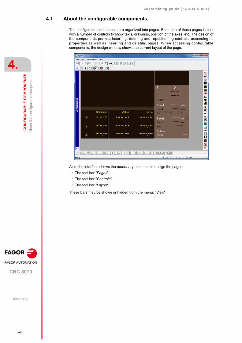
Customizing guide (FGUIM & API).
CNC 8070
4.
CO
NF
IGU
RA
BL
E C
OM
PO
NE
NT
S
Abo
ut th
e co
nfig
ura
ble
com
pone
nts
.
·44·
(REF: 1810)
4.1 About the configurable components.
The configurable components are organized into pages. Each one of these pages is builtwith a number of controls to show texts, drawings, position of the axes, etc. The design ofthe components permits inserting, deleting and repositioning controls, accessing itsproperties as well as inserting and deleting pages. When accessing configurablecomponents, the design window shows the current layout of the page.
Also, the interface shows the necessary elements to design the pages:
• The tool bar "Pages".
• The tool bar "Controls".
• The tool bar "Layout".
These bars may be shown or hidden from the menu: "View".
Customizing guide (FGUIM & API).
CNC 8070
CO
NF
IGU
RA
BL
E C
OM
PO
NE
NT
S
4.
Ove
rall
desi
gn.
Add
ing
an
d de
letin
g co
mpo
nen
ts a
nd u
ser
cycl
es.
·45·
(REF: 1810)
4.2 Overall design. Adding and deleting components and user cycles.
The "Components" menu is only visible when the focus (cursor) is on that left panel of thescreen; i.e. on the list of the system components.
Adding components
Use the "Add" option of the "Components" menu to add new components to the system. Thename assigned to the new component will appear on the component list.
Deleting components
Use the “Delete“ option of the “Components” menu to remove user components from theconfiguration. The "Undo" option cannot be used to recover the component. For safety, thecomponents supplied by Fagor cannot be deleted.
Updating the components at the CNC.
Once a component has been designed or modified, it is updated at the CNC the next timeit is turned on. For the changes to be assumed at the CNC, they must be previously savedfrom the FGUIM.
Customizing guide (FGUIM & API).
CNC 8070
4.
CO
NF
IGU
RA
BL
E C
OM
PO
NE
NT
S
Des
ign
ing
a c
ompo
nen
t. A
ddi
ng
and
de
letin
g c
ompo
nen
ts.
·46·
(REF: 1810)
4.3 Designing a component. Adding and deleting components.
User components are organized into different pages. A component may consist of up to 5different pages.
Selecting the various pages (screens).
The various pages of the components are selected as follows:
• Using the "Next page" option of the "Pages" menu. When reaching the last one defined,it starts at the first one again.
• Using the following buttons:
Insert new pages.
New pages are inserted using the "Insert Before" and "Insert After" options of the"Pages"menu. These options refer to the possibility to create a page before or after thecurrent page. It creates an empty page and with the same background color as the currentone.
Delete pages.
The "Delete Page" option of the "Pages" menu deletes the current page and all the controlsit contains.
Importing and exporting pages of the components.
All the pages of a component may be exported and imported. This operation is carried outusing the "Export" (or "Import") options of the "Components" menu. The two options are onlyavailable if the focus (cursor is on the left panel of the screen; i.e. on the list of the systemcomponents.
Exporting pages of a component.
After selecting the "Export" option, it requests the directory where to save the pages. Itexports the pages of the component selected from the list of components, not those of thecomponent being displayed.
The pages that are exported are the ones used by the FGUIM, not the ones saved in thedisk. This makes it possible to modify the component, and without saving it, export its pageswith the modifications made. The component will not assume the modifications until thechanges are saved; "Save" option of the "File" menu.
Importing pages of a component.
After selecting the "Import" option, it requests the directory from which to restore the pages.It imports the pages into the component selected from the list of components, not into thecomponent being displayed.
The component will not assume the new pages until the changes are saved; "Save" optionof the "File" menu. If after importing the pages, you quit the FGUIM without saving thechanges, the component remains as it was. Likewise, if after importing the pages, thecomponent is loaded (by double-clicking on it), it recovers the original pages.
Previous page.
Next page.
It accesses directly the page it indicates.
Customizing guide (FGUIM & API).
CNC 8070
CO
NF
IGU
RA
BL
E C
OM
PO
NE
NT
S
4.
Des
ign
ing
the
page
s of
the
com
pone
nts
.
·47·
(REF: 1810)
4.4 Designing the pages of the components.
When designing of a page, it is possible to insert, delete and reposition the controls andaccess its properties.
Customize the page background.
Clicking the right button of the mouse on the page background displays the followingproperties menu:
• "Window Size". For now, it is only possible to create windows using the size indicatedin the configuration file (ini) of the component.
• Use Background - Color" to modify the background color for the page.
• Use Background - Picture" to modify the background bitmap for the page. To deselectthis bitmap, select a background color again. The selected image can only be displayedin an external application.
Insert a control.
To insert a control, first select one from the control bar. Then, click the left button of the buttonand draw a rectangle in the design window. The control is inserted into the drawn rectangle.
The control may be drawn anywhere in the design window. It may then be moved anywhereelse, even modify its size.
Selecting a control from the page.
To carry out any operation with a control or a group of controls, they have to be selected inthe design window. To select only one control, just click on it with the left button of the mouse.To select several controls, hold the [CTRL] key down while selecting them. When a controlis selected, a white border appears around it.
To select the inserted controls, there must be no active buttons on the control bar.
Deleting a control from the page.
To delete a control from the page, select it and press the [DEL] key.
Modifying the location and size of a control.
To modify the size or the position of a control, it must be selected. The size of the controlcan be modified by clicking on the outer border and dragging it. The control may be movedaround in the window by clicking inside the control and dragging it around. The size andposition of a control can also be modified from the properties pallet. See chapter"5 Configurable components List of controls.".
Laying out a group of controls.
The buttons on the drawing bar may be used to adjust the relative position of the controlswith respect to one another or to the design window. See "4.4.1 Working with a group ofcontrols." on page 49.
Tabulation sequence.
The tabulation sequence of the controls of a page indicates the order in which they will beactivated in the CNC. The tabulation sequence may be set as follows:
• From the properties of the controls. In this case, for each control, one must define theposition it occupies in the tabulation sequence.
Customizing guide (FGUIM & API).
CNC 8070
4.
CO
NF
IGU
RA
BL
E C
OM
PO
NE
NT
S
Des
ign
ing
the
page
s of
the
com
pone
nts
.
·48·
(REF: 1810)
• Using the "Tabulation sequence" option of the "View" menu or its equivalent button onthe "Pages" bar.
On the pages of user components, the arrow keys and the tab of the keyboard always letsyou change the focus to the previous or next control according to a set tab order.
On the pages of Fagor components, the arrow keys, the tab and the [ENTER] key only letsyou change the focus to the controls Varx, EditX, Multistatic, Button and Data if theirFocusChangeKeys property allows it.
Properties of the controls.
The controls may be configured using a number of properties. See "5.1 Properties of thecontrols." on page 53.These properties may be accessed:
• By clickingon the control with the right button of the mouse.
• Using the "Properties" option of the "View" menu.
In this case, the controls must be selected in the order in which you would like themto be activated.
Customizing guide (FGUIM & API).
CNC 8070
CO
NF
IGU
RA
BL
E C
OM
PO
NE
NT
S
4.
Des
ign
ing
the
page
s of
the
com
pone
nts
.
·49·
(REF: 1810)
4.4.1 Working with a group of controls.
The following buttons may be used to set the size and position of the controls. Dependingon the number of controls selected, some buttons might not be available.
To align and resize the controls exactly, sometimes the white border of the controldisappears. This means that the control cannot be resized manually. If necessary, this couldbe avoided by pressing the [ALT] key and the button at the same time.
Aligning controls.
Control layout.
Control resizing.
Left alignment.
Aligns the controls with the left border of the last selected control. This button isactive when selecting more than one control.
Right alignment.
Same as the previous one, but with the right border.
Top alignment.
Same as the previous one, but with the top border.
Bottom alignment.
Same as the previous one, but with the bottom border.
Horizontal alignment.
It aligns (merges) two controls horizontally.
Vertical alignment.
It aligns (merges) two controls vertically.
Vertical centering.
It centers the selected control(s) vertically in the window.
Horizontal centering.
It centers the selected control(s) horizontally in the window.
Horizontal layout.
It lays out the selected controls evenly and horizontally. There must be at leastthree controls selected and they must not overlap horizontally.
Vertical layout.
Same as the previous one, but vertically.
Adjusting a window.
Resizes two controls to occupy the whole window. Each one of them occupieshalf the width and the full height of the window.
Resizing in width.
Resizes the controls so their width is the same as that of the last selected control.
Resizing in height.
Resizes the controls so their height is the same as that of the last selected control.
Full resizing.
Resizes the controls so their height and width is the same as that of the lastselected control.
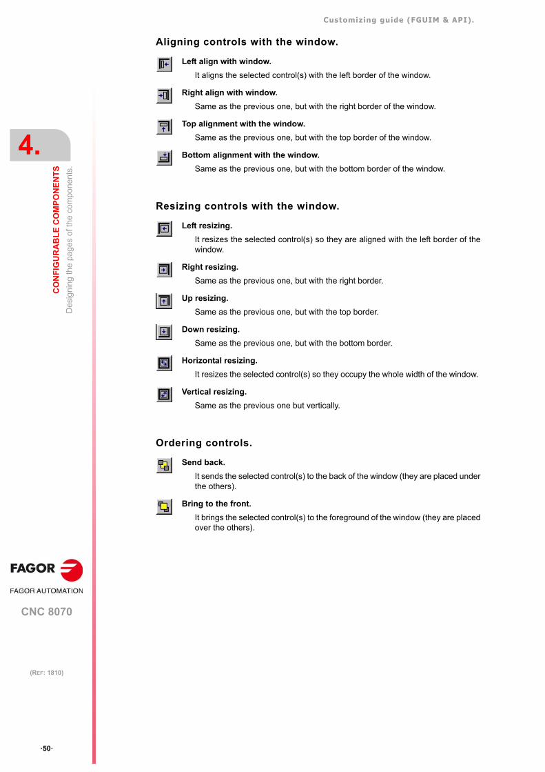
Customizing guide (FGUIM & API).
CNC 8070
4.
CO
NF
IGU
RA
BL
E C
OM
PO
NE
NT
S
Des
ign
ing
the
page
s of
the
com
pone
nts
.
·50·
(REF: 1810)
Aligning controls with the window.
Resizing controls with the window.
Ordering controls.
Left align with window.
It aligns the selected control(s) with the left border of the window.
Right align with window.
Same as the previous one, but with the right border of the window.
Top alignment with the window.
Same as the previous one, but with the top border of the window.
Bottom alignment with the window.
Same as the previous one, but with the bottom border of the window.
Left resizing.
It resizes the selected control(s) so they are aligned with the left border of thewindow.
Right resizing.
Same as the previous one, but with the right border.
Up resizing.
Same as the previous one, but with the top border.
Down resizing.
Same as the previous one, but with the bottom border.
Horizontal resizing.
It resizes the selected control(s) so they occupy the whole width of the window.
Vertical resizing.
Same as the previous one but vertically.
Send back.
It sends the selected control(s) to the back of the window (they are placed underthe others).
Bring to the front.
It brings the selected control(s) to the foreground of the window (they are placedover the others).
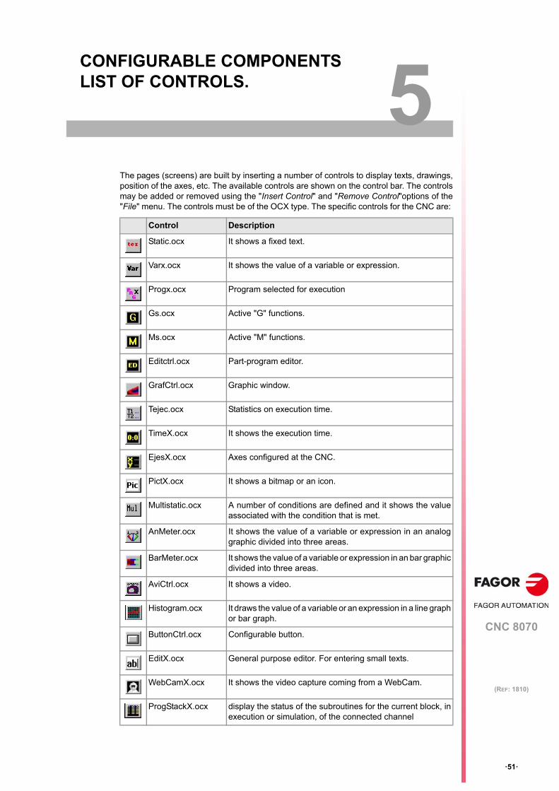
CNC 8070
5
·51·
(REF: 1810)
5. CONFIGURABLE COMPONENTS LIST OF CONTROLS.
The pages (screens) are built by inserting a number of controls to display texts, drawings,position of the axes, etc. The available controls are shown on the control bar. The controlsmay be added or removed using the "Insert Control" and "Remove Control"options of the"File" menu. The controls must be of the OCX type. The specific controls for the CNC are:
Control Description
Static.ocx It shows a fixed text.
Varx.ocx It shows the value of a variable or expression.
Progx.ocx Program selected for execution
Gs.ocx Active "G" functions.
Ms.ocx Active "M" functions.
Editctrl.ocx Part-program editor.
GrafCtrl.ocx Graphic window.
Tejec.ocx Statistics on execution time.
TimeX.ocx It shows the execution time.
EjesX.ocx Axes configured at the CNC.
PictX.ocx It shows a bitmap or an icon.
Multistatic.ocx A number of conditions are defined and it shows the valueassociated with the condition that is met.
AnMeter.ocx It shows the value of a variable or expression in an analoggraphic divided into three areas.
BarMeter.ocx It shows the value of a variable or expression in an bar graphicdivided into three areas.
AviCtrl.ocx It shows a video.
Histogram.ocx It draws the value of a variable or an expression in a line graphor bar graph.
ButtonCtrl.ocx Configurable button.
EditX.ocx General purpose editor. For entering small texts.
WebCamX.ocx It shows the video capture coming from a WebCam.
ProgStackX.ocx display the status of the subroutines for the current block, inexecution or simulation, of the connected channel
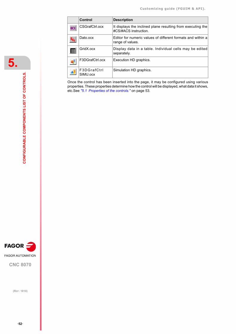
Customizing guide (FGUIM & API).
CNC 8070
5.
CO
NF
IGU
RA
BL
E C
OM
PO
NE
NT
S L
IST
OF
CO
NT
RO
LS
.
·52·
(REF: 1810)
Once the control has been inserted into the page, it may be configured using variousproperties. These properties determine how the control will be displayed, what data it shows,etc.See "5.1 Properties of the controls." on page 53.
CSGrafCtrl.ocx It displays the inclined plane resulting from executing the#CS/#ACS instruction.
Dato.ocx Editor for numeric values of different formats and within arange of values.
GridX.ocx Display data in a table. Individual cells may be editedseparately.
F3DGrafCtrl.ocx Execution HD graphics.
F3DGra fC t r lSIMU.ocx
Simulation HD graphics.
Control Description
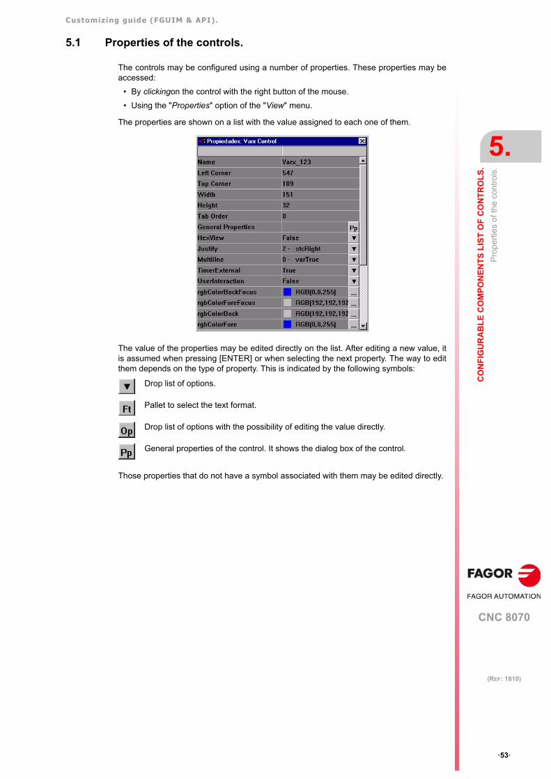
Customizing guide (FGUIM & API).
CNC 8070
CO
NF
IGU
RA
BL
E C
OM
PO
NE
NT
S L
IST
OF
CO
NT
RO
LS
.
5.
Pro
pert
ies
of t
he
cont
rols
.
·53·
(REF: 1810)
5.1 Properties of the controls.
The controls may be configured using a number of properties. These properties may beaccessed:
• By clickingon the control with the right button of the mouse.
• Using the "Properties" option of the "View" menu.
The properties are shown on a list with the value assigned to each one of them.
The value of the properties may be edited directly on the list. After editing a new value, itis assumed when pressing [ENTER] or when selecting the next property. The way to editthem depends on the type of property. This is indicated by the following symbols:
Those properties that do not have a symbol associated with them may be edited directly.
Drop list of options.
Pallet to select the text format.
Drop list of options with the possibility of editing the value directly.
General properties of the control. It shows the dialog box of the control.
Customizing guide (FGUIM & API).
CNC 8070
5.
CO
NF
IGU
RA
BL
E C
OM
PO
NE
NT
S L
IST
OF
CO
NT
RO
LS
.
Pro
pert
ies
of t
he
cont
rols
.
·54·
(REF: 1810)
5.1.1 Variables and expressions in the controls.
Certain controls show the value of a variable or an expression.
• The list of valid variables may be consulted in the installation manual. Variables G.GS[n]and G.GUP[n] may be written as Gn and Pn.
Example: (G0 * A.APPOS.1 ) + (G1 * A.ATIPPOS.1)
• If the axis number or name is omitted for the variables, the control applies the expressionto all axes (only in the Ejesx control).
• The expressions may be arithmetic, binary or relational (only with the "MultiStatic"control).
• The operations that cannot be carried out, (division by 0, negative factorial, etc.) willreturn a 0; thus, for example, [47+12/0] = [47 + 0] = 47
Arithmetic expressions.
Their result is a numerical value. Arithmetic expressions may be defined using the followingconstants, arithmetic operations, mathematical functions and trigonometric functions. In theexamples, "x" and "y" indicate constants, variables or expressions.
Constants.
The constant values may be entered in these formats: decimal (value), hexadecimal ($value)or binary (Bvalue).
This expression is evaluated as follows:G0 + APOS * (NOT G0 * ATIPPOS + P110) - PLCOF
For axis 1:G0 + A.APOS.1 * (NOT G0 * A.ATIPPOS.1 + P110) - A.PLCOF.1For axis 2:G0 + A.APOS.2 * (NOT G0 * A.ATIPPOS.2 + P110) - A.PLCOF.2
PI Pi value.
MMPERI Millimeters per inch.
IPERMM Inches per millimeters.
Customizing guide (FGUIM & API).
CNC 8070
CO
NF
IGU
RA
BL
E C
OM
PO
NE
NT
S L
IST
OF
CO
NT
RO
LS
.
5.
Pro
pert
ies
of t
he
cont
rols
.
·55·
(REF: 1810)
Arithmetic operations.
Mathematical functions.
Conversion expressions.
Trigonometric functions.
Binary expressions.
Their result is a binary value. In the examples, "x" and "y" indicate constants, variables orexpressions.
Binary operations.
It makes a binary comparison between bits.
x + y Add.
x - y Subtract.
x * y Multiply.
x / y Divide.
x % y Module or remainder of a division.
x ^ y Exponential.
x! Factorial.
SQRT x Square root.
LOG x Decimal logarithm.
INVLOG x Decimal exponent.
LN x Neperian logarithm.
INVLN x "e" function.
INTEGRAL x Integral calculation.
ABS x Absolute value.
INT x Integer value.
MMTOI From millimeters to inches.
ITOMM From inches to millimeters.
SIN x Sine.
COS x Cosine.
TAN x Tangent.
INVSIN x Arcsine (1/SINE)
INVCOS x Arc-cosine (1/COS).
INVTAN x Arc-tangent (1/TAN).
SH x Hyperbolic sine.
CH x Hyperbolic cosine.
TH x Hyperbolic tangent.
INVSH x Hyperbolic arcsine (1/SH)
INVCH x Hyperbolic arc-cosine (1/CH)
INVTH x Hyperbolic arc-tangent (1/TH).
binnot x Complement.
Customizing guide (FGUIM & API).
CNC 8070
5.
CO
NF
IGU
RA
BL
E C
OM
PO
NE
NT
S L
IST
OF
CO
NT
RO
LS
.
Pro
pert
ies
of t
he
cont
rols
.
·56·
(REF: 1810)
Binary operations.
It makes binary comparison between constants, variables or expressions.
Relational expressions.
Their result is either "true" or "false". They are only valid in the "multistatic" control. In theexamples, "x" and "y" indicate constants, variables or expressions.
Relational operations.
x binand y Binary AND.
x binor y Binary OR.
x binxor y Binary XOR.
NOT x Complement.
x AND y Binary AND.
x OR y Binary OR.
x == y Equal to.
x < y Less than.
x <= y Less than or equal to.
x > y Greater than.
x >= y Greater than or equal to.
Customizing guide (FGUIM & API).
CNC 8070
CO
NF
IGU
RA
BL
E C
OM
PO
NE
NT
S L
IST
OF
CO
NT
RO
LS
.
5.
Pro
pert
ies
of t
he
cont
rols
.
·57·
(REF: 1810)
5.1.2 Texts in different languages in the controls.
The texts shown by certain controls may now be multilingual; in other words, that dependingon the language selected at the CNC, the texts may be displayed in that language.
The text shown by the controls is defined in its properties. To make a text languagedependent, instead of defining the text directly, define an identifier that will be associatedwith the text to be shown.
The controls that admit identifiers may be on any page of any component.
Defining the identifiers in the controls.
The text identifiers may have any name but it must always start with the prefix "IDS_" (e.g.IDS_MYTEXT, IDS_VALUE, IDS_CONTROLTEXT1).
The controls where these identifiers may be defined are:
• The "Text" property of the –Static– control.
• The "Title" property of the –EjesX– control.
• The "Title" property of the –Histogram– control.
• The values of the conditions in the –Multistatic– control. The identifiers cannot be usedwhen the value is an expression or a drawing.
• The "Title" property of a softkey.
The text editor.
Once in the editor, its operation is very easy. Just select the language for the text and addlines like: "Identifier" = "Text".
For example, to define texts in Spanish and English in a control, proceed as follows. As anexample, we'll use a –Static– control.
1 Write the identifier "IDS_MITEXT" in the "Text" property of the control.
2 Select the "Spanish" language at the editor and write the following.
IDS_MYTEXT = "Mi texto"
3 Select the "English" language and write the following.
IDS_MYTEXT = "My text"
This way, when Spanish has been selected at the CNC, the control will show the text "Mitexto". When English has been selected at the CNC, the control will show the text "My text".
Use the text editor of the FGUIM to associate the identifiers to the texts. To access the editor,select the Text editor" option of the "View" menu or the corresponding button.
The text editor can also be used to edit multilingual texts for the scripts. In these cases, the identifiersand the texts must be in a section with the name of the component that owns the script. See "8.2 Textsin different languages in the scripts." on page 151.
i
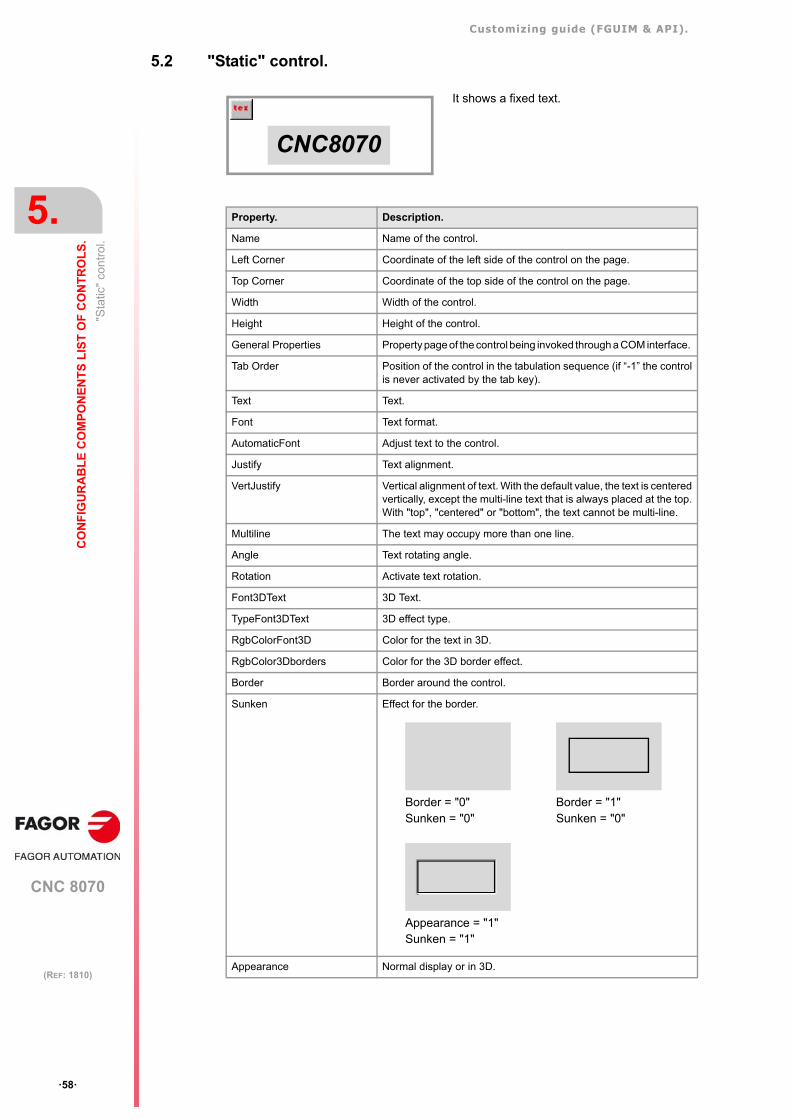
Customizing guide (FGUIM & API).
CNC 8070
5.
CO
NF
IGU
RA
BL
E C
OM
PO
NE
NT
S L
IST
OF
CO
NT
RO
LS
.
"Sta
tic"
cont
rol.
·58·
(REF: 1810)
5.2 "Static" control.
It shows a fixed text.
CNC8070
Property. Description.
Name Name of the control.
Left Corner Coordinate of the left side of the control on the page.
Top Corner Coordinate of the top side of the control on the page.
Width Width of the control.
Height Height of the control.
General Properties Property page of the control being invoked through a COM interface.
Tab Order Position of the control in the tabulation sequence (if “-1” the controlis never activated by the tab key).
Text Text.
Font Text format.
AutomaticFont Adjust text to the control.
Justify Text alignment.
VertJustify Vertical alignment of text. With the default value, the text is centeredvertically, except the multi-line text that is always placed at the top.With "top", "centered" or "bottom", the text cannot be multi-line.
Multiline The text may occupy more than one line.
Angle Text rotating angle.
Rotation Activate text rotation.
Font3DText 3D Text.
TypeFont3DText 3D effect type.
RgbColorFont3D Color for the text in 3D.
RgbColor3Dborders Color for the 3D border effect.
Border Border around the control.
Sunken Effect for the border.
Appearance Normal display or in 3D.
Border = "0"Sunken = "0"
Border = "1"Sunken = "0"
Appearance = "1"Sunken = "1"
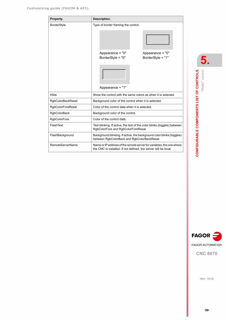
Customizing guide (FGUIM & API).
CNC 8070
CO
NF
IGU
RA
BL
E C
OM
PO
NE
NT
S L
IST
OF
CO
NT
RO
LS
.
5.
"Sta
tic"
cont
rol.
·59·
(REF: 1810)
BorderStyle Type of border framing the control.
Hilite Show the control with the same colors as when it is selected.
RgbColorBackResal Background color of the control when it is selected.
RgbColorForeResal Color of the control data when it is selected.
RgbColorBack Background color of the control.
RgbColorFore Color of the control data.
FlashText Text blinking. If active, the text of the color blinks (toggles) betweenRgbColorFore and RgbColorForeResal.
FlashBackground Background blinking. If active, the background color blinks (toggles)between RgbColorBack and RgbColorBackResal.
RemoteServerName Name or IP address of the remote server for variables, the one wherethe CNC is installed. If not defined, the server will be local.
Property. Description.
Appearance = "0"BorderStyle = "0"
Appearance = "0"BorderStyle = "1"
Appearance = "1"
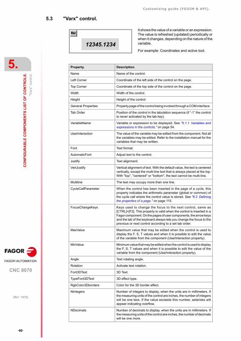
Customizing guide (FGUIM & API).
CNC 8070
5.
CO
NF
IGU
RA
BL
E C
OM
PO
NE
NT
S L
IST
OF
CO
NT
RO
LS
.
"Var
x" c
ontr
ol.
·60·
(REF: 1810)
5.3 "Varx" control.
It shows the value of a variable or an expression.The value is refreshed (updated) periodically orwhen it changes, depending on the nature of thevariable.
For example: Coordinates and active tool.
12345.1234
Property. Description.
Name Name of the control.
Left Corner Coordinate of the left side of the control on the page.
Top Corner Coordinate of the top side of the control on the page.
Width Width of the control.
Height Height of the control.
General Properties Property page of the control being invoked through a COM interface.
Tab Order Position of the control in the tabulation sequence (if “-1” the controlis never activated by the tab key).
VariableName Variable or expression to be displayed. See "5.1.1 Variables andexpressions in the controls." on page 54.
UserInteraction The value of the variable may be edited from the component. Not allthe variables may be edited. Refer to the installation manual for thevariables that may be written.
Font Text format.
AutomaticFont Adjust text to the control.
Justify Text alignment.
VertJustify Vertical alignment of text. With the default value, the text is centeredvertically, except the multi-line text that is always placed at the top.With "top", "centered" or "bottom", the text cannot be multi-line.
Multiline The text may occupy more than one line.
CycleCallParameter When the control has been inserted in the page of a cycle, thisproperty indicates the arithmetic parameter (global or common) ofthe cycle call where the control value is stored. See "6.2 Definingthe properties of a page." on page 115.
FocusChangeKeys Keys used to change the focus to the next control, same as[CTRL]+[F2]. This property is valid when the control is inserted in aFagor component. On the pages of user components, the arrow keysand the tab of the keyboard always lets you change the focus to theprevious or next control according to a set tab order.
MaxValue Maximum value that may be edited when the control is used todisplay the F, S, T values and when it is possible to edit the valueof the variable from the component (UserInteraction property).
MinValue Minimum value that may be edited when the control is used to displaythe F, S, T values and when it is possible to edit the value of thevariable from the component (UserInteraction property).
Angle Text rotating angle.
Rotation Activate text rotation.
Font3DText 3D Text.
TypeFont3DText 3D effect type.
RgbColor3Dborders Color for the 3D border effect.
NIntegers Number of integers to display, when the units are in millimeters. Ifthe measuring units of the control are inches, the number of integerswill be one less. If the value exceeds this number, asterisks willappear indicating overflow.
NDecimals Number of decimals to display, when the units are in millimeters. Ifthe measuring units of the control are inches, the number of decimalswill be one more.
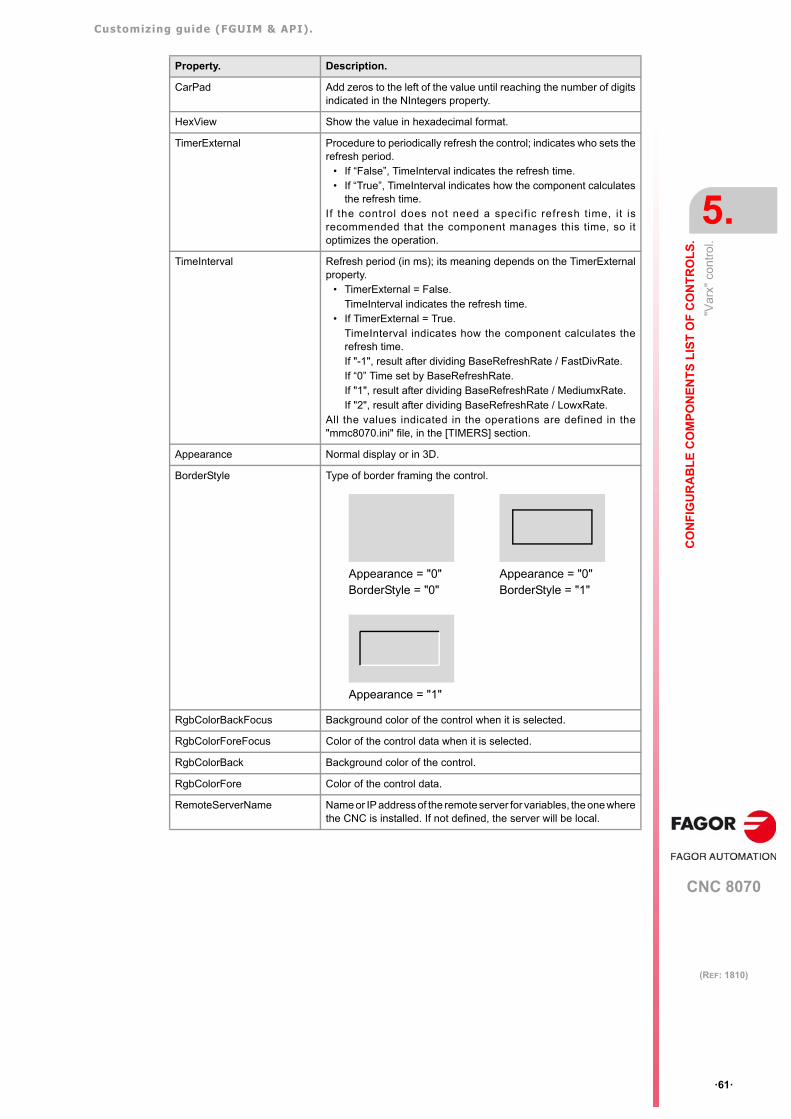
Customizing guide (FGUIM & API).
CNC 8070
CO
NF
IGU
RA
BL
E C
OM
PO
NE
NT
S L
IST
OF
CO
NT
RO
LS
.
5.
"Var
x" c
ontr
ol.
·61·
(REF: 1810)
CarPad Add zeros to the left of the value until reaching the number of digitsindicated in the NIntegers property.
HexView Show the value in hexadecimal format.
TimerExternal Procedure to periodically refresh the control; indicates who sets therefresh period.
• If “False”, TimeInterval indicates the refresh time.• If “True”, TimeInterval indicates how the component calculates
the refresh time.If the control does not need a specif ic refresh time, it isrecommended that the component manages this time, so itoptimizes the operation.
TimeInterval Refresh period (in ms); its meaning depends on the TimerExternalproperty.
• TimerExternal = False.TimeInterval indicates the refresh time.
• If TimerExternal = True.TimeInterval indicates how the component calculates therefresh time.If "-1", result after dividing BaseRefreshRate / FastDivRate.If “0” Time set by BaseRefreshRate.If "1", result after dividing BaseRefreshRate / MediumxRate.If "2", result after dividing BaseRefreshRate / LowxRate.
All the values indicated in the operations are defined in the"mmc8070.ini" file, in the [TIMERS] section.
Appearance Normal display or in 3D.
BorderStyle Type of border framing the control.
RgbColorBackFocus Background color of the control when it is selected.
RgbColorForeFocus Color of the control data when it is selected.
RgbColorBack Background color of the control.
RgbColorFore Color of the control data.
RemoteServerName Name or IP address of the remote server for variables, the one wherethe CNC is installed. If not defined, the server will be local.
Property. Description.
Appearance = "0"BorderStyle = "0"
Appearance = "0"BorderStyle = "1"
Appearance = "1"
Customizing guide (FGUIM & API).
CNC 8070
5.
CO
NF
IGU
RA
BL
E C
OM
PO
NE
NT
S L
IST
OF
CO
NT
RO
LS
.
"Var
x" c
ontr
ol.
·62·
(REF: 1810)
5.3.1 Methods of the "VarX" control to be used in scripts.
The VariableName property may be modified dynamically from a script using the followingmethods of the control.
BSTR GetConnectedVariable()
It returns the name of the variable or expression currently being displayed.
boolean ConnectToVariable (BSTR variableName)
It connects to the variable or expression indicated by parameter; this way, it goes on to displaythat expression or variable. This method returns FALSE if the parameter does not indicatea valid name of variable or expression.
msgbox "Variable:" + MyVarx.GetConnectedVariable
If (MyVarx.GetConnectedVariable = "A.ATIPPOS.X") Then MyVarx.ConnectToVariable "A.ATIPPOS.Y"End If
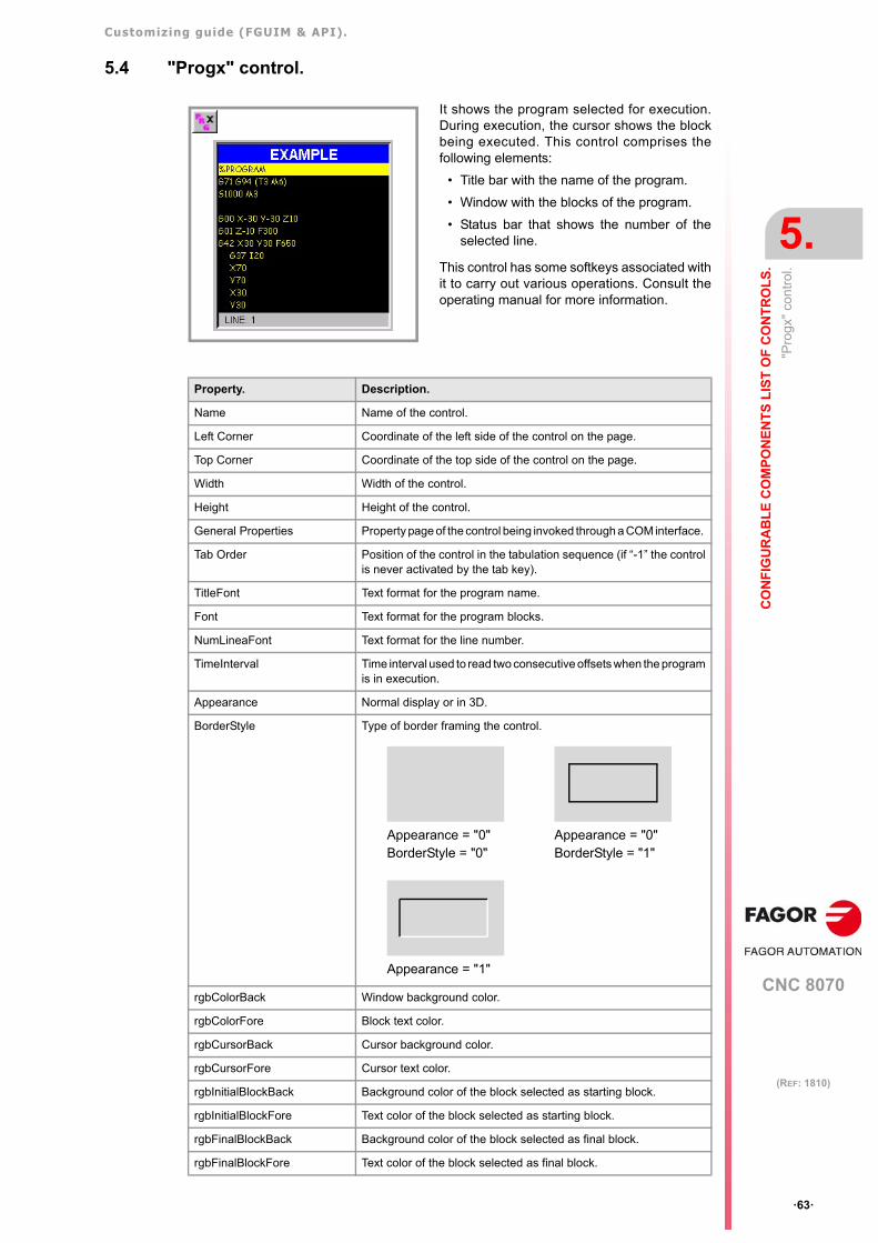
Customizing guide (FGUIM & API).
CNC 8070
CO
NF
IGU
RA
BL
E C
OM
PO
NE
NT
S L
IST
OF
CO
NT
RO
LS
.
5.
"Pro
gx"
cont
rol.
·63·
(REF: 1810)
5.4 "Progx" control.
It shows the program selected for execution.During execution, the cursor shows the blockbeing executed. This control comprises thefollowing elements:
• Title bar with the name of the program.
• Window with the blocks of the program.
• Status bar that shows the number of theselected line.
This control has some softkeys associated withit to carry out various operations. Consult theoperating manual for more information.
Property. Description.
Name Name of the control.
Left Corner Coordinate of the left side of the control on the page.
Top Corner Coordinate of the top side of the control on the page.
Width Width of the control.
Height Height of the control.
General Properties Property page of the control being invoked through a COM interface.
Tab Order Position of the control in the tabulation sequence (if “-1” the controlis never activated by the tab key).
TitleFont Text format for the program name.
Font Text format for the program blocks.
NumLineaFont Text format for the line number.
TimeInterval Time interval used to read two consecutive offsets when the programis in execution.
Appearance Normal display or in 3D.
BorderStyle Type of border framing the control.
rgbColorBack Window background color.
rgbColorFore Block text color.
rgbCursorBack Cursor background color.
rgbCursorFore Cursor text color.
rgbInitialBlockBack Background color of the block selected as starting block.
rgbInitialBlockFore Text color of the block selected as starting block.
rgbFinalBlockBack Background color of the block selected as final block.
rgbFinalBlockFore Text color of the block selected as final block.
Appearance = "0"BorderStyle = "0"
Appearance = "0"BorderStyle = "1"
Appearance = "1"
Customizing guide (FGUIM & API).
CNC 8070
5.
CO
NF
IGU
RA
BL
E C
OM
PO
NE
NT
S L
IST
OF
CO
NT
RO
LS
.
"Pro
gx"
cont
rol.
·64·
(REF: 1810)
rgbNumLineaBack Background color of the line number.
rgbNumLineaFore Text color of the line number.
rgbTitleOffBack Background color of the title when the control is disabled.
rgbTitleOffFore Text color of the title when the control is disabled.
rgbTitleOnFore Text color of the title when the control is enabled.
rgbTitleOnBack Background color of the title when the control is enabled.
RemoteServerName Name or IP address of the remote server for variables, the one wherethe CNC is installed. If not defined, the server will be local.
Channel Channel whose data is displayed. If set to ·0·, it displays the data ofthe active channel.
Property. Description.
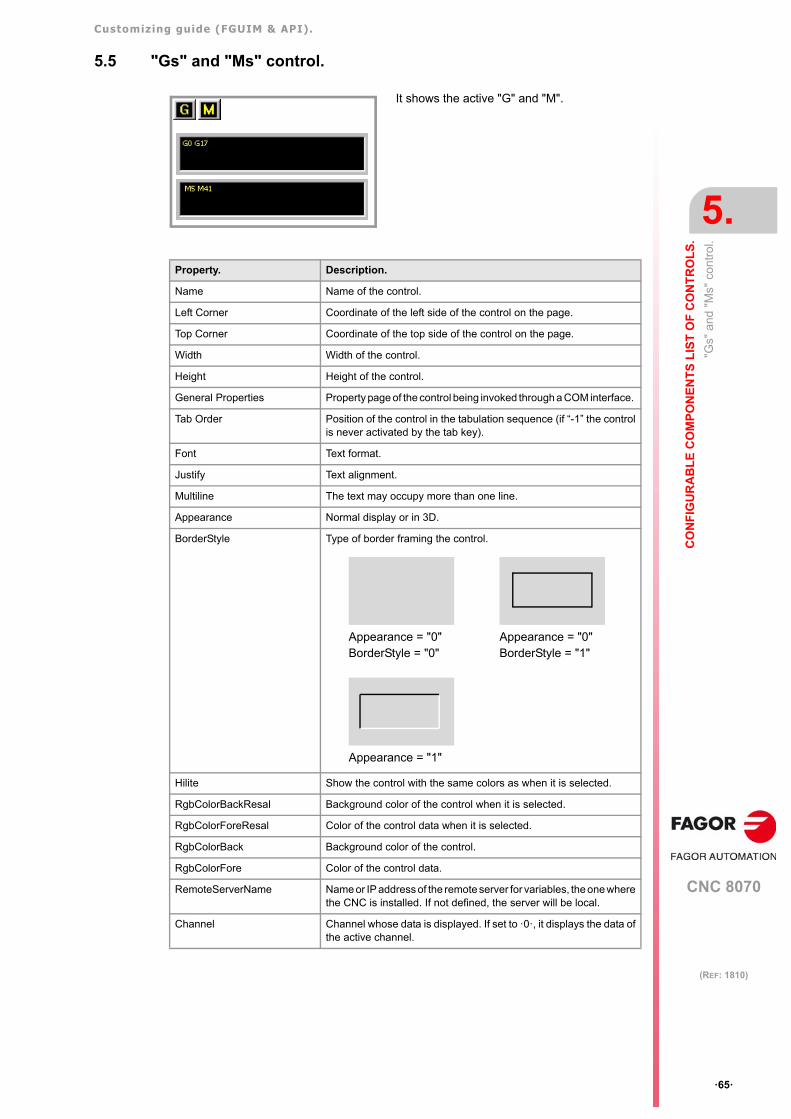
Customizing guide (FGUIM & API).
CNC 8070
CO
NF
IGU
RA
BL
E C
OM
PO
NE
NT
S L
IST
OF
CO
NT
RO
LS
.
5.
"Gs"
and
"M
s" c
ontr
ol.
·65·
(REF: 1810)
5.5 "Gs" and "Ms" control.
It shows the active "G" and "M".
Property. Description.
Name Name of the control.
Left Corner Coordinate of the left side of the control on the page.
Top Corner Coordinate of the top side of the control on the page.
Width Width of the control.
Height Height of the control.
General Properties Property page of the control being invoked through a COM interface.
Tab Order Position of the control in the tabulation sequence (if “-1” the controlis never activated by the tab key).
Font Text format.
Justify Text alignment.
Multiline The text may occupy more than one line.
Appearance Normal display or in 3D.
BorderStyle Type of border framing the control.
Hilite Show the control with the same colors as when it is selected.
RgbColorBackResal Background color of the control when it is selected.
RgbColorForeResal Color of the control data when it is selected.
RgbColorBack Background color of the control.
RgbColorFore Color of the control data.
RemoteServerName Name or IP address of the remote server for variables, the one wherethe CNC is installed. If not defined, the server will be local.
Channel Channel whose data is displayed. If set to ·0·, it displays the data ofthe active channel.
Appearance = "0"BorderStyle = "0"
Appearance = "0"BorderStyle = "1"
Appearance = "1"
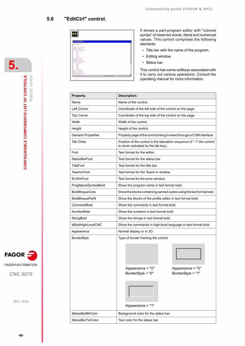
Customizing guide (FGUIM & API).
CNC 8070
5.
CO
NF
IGU
RA
BL
E C
OM
PO
NE
NT
S L
IST
OF
CO
NT
RO
LS
.
"Edi
tCtr
l" c
ontr
ol.
·66·
(REF: 1810)
5.6 "EditCtrl" control.
It shows a part-program editor with "coloredsyntax" of reserved words, literal and numericalvalues. This control comprises the followingelements:
• Title bar with the name of the program.
• Editing window.
• Status bar.
This control has some softkeys associated withit to carry out various operations. Consult theoperating manual for more information.
Property. Description.
Name Name of the control.
Left Corner Coordinate of the left side of the control on the page.
Top Corner Coordinate of the top side of the control on the page.
Width Width of the control.
Height Height of the control.
General Properties Property page of the control being invoked through a COM interface.
Tab Order Position of the control in the tabulation sequence (if “-1” the controlis never activated by the tab key).
Font Text format for the editor.
StatusBarFont Text format for the status bar.
TitleFont Text format for the title bar.
TeachInFont Text format for the Teach-in window.
ErrWinFont Text format for the error window.
ProgNameSymbolBold Show the program name in text format bold.
BoldBloqueCiclo Show the blocks containing canned cycles using the text format bold.
BoldBloquePerfil Show the blocks of the profile editor in text format bold.
CommentBold Show the comments in text format bold.
NumberBold Show the numbers in text format bold.
StringBold Show the strings in text format bold.
bBoldHighLevelCNC Show the commands in high-level language in text format bold.
Appearance Normal display or in 3D.
BorderStyle Type of border framing the control.
StatusBarBkColor Background color for the status bar.
StatusBarTxtColor Text color for the status bar.
Appearance = "0"BorderStyle = "0"
Appearance = "0"BorderStyle = "1"
Appearance = "1"
Customizing guide (FGUIM & API).
CNC 8070
CO
NF
IGU
RA
BL
E C
OM
PO
NE
NT
S L
IST
OF
CO
NT
RO
LS
.
5.
"Edi
tCtr
l" c
ontr
ol.
·67·
(REF: 1810)
rgbColorBackTitle Background color for the title bar.
rgbColorForeTitle Text color for the title bar.
rgbColorBack Editor's background color.
rgbColorFore Editor's text color.
rgbColorBackTeachIn Background color for the Teach-in window.
rgbColorForeTeachIn Text color for the Teach-in window.
ErrWinBkColor Background color for the error window.
ErrWinTxtColor Text color for the error window.
ProgNameSymbolColor Text color for the program name.
ColorBloqueCiclo Text color for blocks containing canned cycles.
ColorBloquePerfil Text color for the blocks of the profile editor.
CommentColor Text color for comments.
NumberColor Text color for numbers.
rgbColorHighLevelCNC Text color for the high-level commands.
StringColor Text color for strings.
bWithTitle Show the editor's title bar.
CaseSensitive The reserved words are case sensitive.
MaxNumberErrors Maximum number of errors to be displayed in the error window.
bLineSintaxCheck Activate the line syntax check.
bSaveAlways Save the program every time it is modified.
bHideCyclProf Hide the blocks of the cycle editor and of the profile editor.
bSintaxColouring Activate the colored syntax in the editor.
bProgHelpOn Activate programming assistance.
bEditor8055On Activate the compatibility of the editor with the 8055 CNC language.
RemoteServerName Name or IP address of the remote server for variables, the one wherethe CNC is installed. If not defined, the server will be local.
Channel Channel whose data is displayed. If set to ·0·, it displays the data ofthe active channel.
Property. Description.
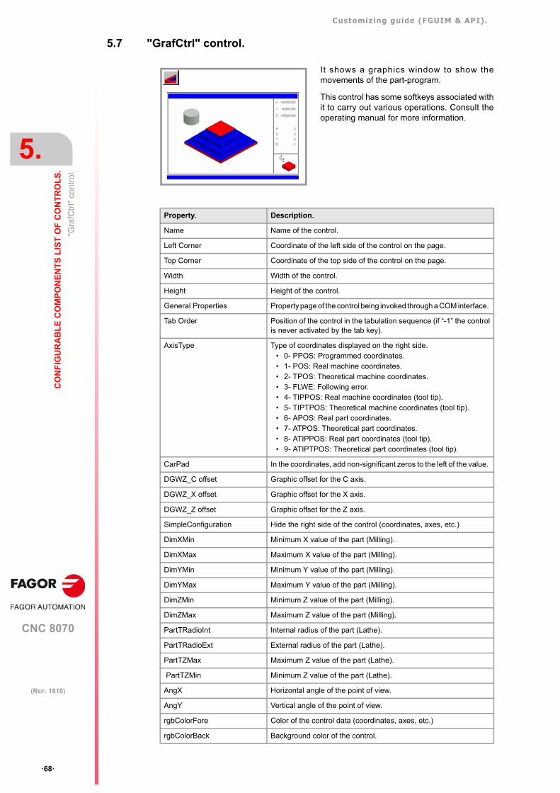
Customizing guide (FGUIM & API).
CNC 8070
5.
CO
NF
IGU
RA
BL
E C
OM
PO
NE
NT
S L
IST
OF
CO
NT
RO
LS
.
"Gra
fCtr
l" c
ontr
ol.
·68·
(REF: 1810)
5.7 "GrafCtrl" control.
It shows a graphics window to show themovements of the part-program.
This control has some softkeys associated withit to carry out various operations. Consult theoperating manual for more information.
Property. Description.
Name Name of the control.
Left Corner Coordinate of the left side of the control on the page.
Top Corner Coordinate of the top side of the control on the page.
Width Width of the control.
Height Height of the control.
General Properties Property page of the control being invoked through a COM interface.
Tab Order Position of the control in the tabulation sequence (if “-1” the controlis never activated by the tab key).
AxisType Type of coordinates displayed on the right side. • 0- PPOS: Programmed coordinates.• 1- POS: Real machine coordinates. • 2- TPOS: Theoretical machine coordinates.• 3- FLWE: Following error.• 4- TIPPOS: Real machine coordinates (tool tip).• 5- TIPTPOS: Theoretical machine coordinates (tool tip).• 6- APOS: Real part coordinates.• 7- ATPOS: Theoretical part coordinates.• 8- ATIPPOS: Real part coordinates (tool tip).• 9- ATIPTPOS: Theoretical part coordinates (tool tip).
CarPad In the coordinates, add non-significant zeros to the left of the value.
DGWZ_C offset Graphic offset for the C axis.
DGWZ_X offset Graphic offset for the X axis.
DGWZ_Z offset Graphic offset for the Z axis.
SimpleConfiguration Hide the right side of the control (coordinates, axes, etc.)
DimXMin Minimum X value of the part (Milling).
DimXMax Maximum X value of the part (Milling).
DimYMin Minimum Y value of the part (Milling).
DimYMax Maximum Y value of the part (Milling).
DimZMin Minimum Z value of the part (Milling).
DimZMax Maximum Z value of the part (Milling).
PartTRadioInt Internal radius of the part (Lathe).
PartTRadioExt External radius of the part (Lathe).
PartTZMax Maximum Z value of the part (Lathe).
PartTZMin Minimum Z value of the part (Lathe).
AngX Horizontal angle of the point of view.
AngY Vertical angle of the point of view.
rgbColorFore Color of the control data (coordinates, axes, etc.)
rgbColorBack Background color of the control.
Customizing guide (FGUIM & API).
CNC 8070
CO
NF
IGU
RA
BL
E C
OM
PO
NE
NT
S L
IST
OF
CO
NT
RO
LS
.
5.
"Gra
fCtr
l" c
ontr
ol.
·69·
(REF: 1810)
ColorXInt Color for the internal X of the part (Milling).
ColorXExt Color for the external X of the part (Milling).
ColorYInt Color for the internal Y of the part (Milling).
ColorYExt Color for the external Y of the part (Milling).
ColorZInt Color for the internal Z of the part (Milling).
ColorZExt Color for the external Z of the part (Milling).
ColorLathePart Part color (Lathe).
ColorLatheTool Tool color (Lathe).
ColorLatheClamps Fixture color (Lathe).
ColorThreading Color for threading.
ColorCycles Color for canned cycles.
ColorUnCompensated Color for movements without compensation.
ColorCompensated Color for movements with compensation.
ColorRapid Color for movements in G0.
Channel / Channel2 Channel whose data is displayed. If set to ·0·, it displays the data ofthe active channel. The -1 value indicates that no channel has beenassigned to it. With both properties, it is possible to assign one or two channels tothe graphics so it can display the execution of two channels on asingle graphic (for example, a dual-turret lathe). For example, ifChannel=1 and Channel =2, the graphics will show the execution ofchannels 1 and 2.To show a single channel in the graphics, this channel being alwaysthe active one, set Channel=1 and Channel =-1.When defining these properties, bear in mind the followingrestrictions:
• The Channel2 property cannot have a 0 value. In this case, thecontrol will assume the value of -1; i.e. there is no secondchannel assigned to the graphics.
• Whenever the Channel property is 0, the Channel2 propertymust be -1; i.e. a single channel in the graphics and it always isthe active channel.
Property. Description.
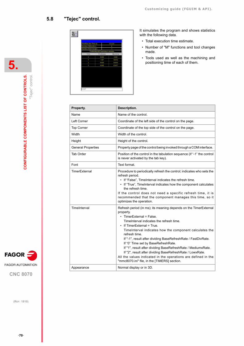
Customizing guide (FGUIM & API).
CNC 8070
5.
CO
NF
IGU
RA
BL
E C
OM
PO
NE
NT
S L
IST
OF
CO
NT
RO
LS
.
"Tej
ec"
cont
rol.
·70·
(REF: 1810)
5.8 "Tejec" control.
It simulates the program and shows statisticswith the following data.
• Total execution time estimate.
• Number of "M" functions and tool changesmade.
• Tools used as well as the machining andpositioning time of each of them.
Property. Description.
Name Name of the control.
Left Corner Coordinate of the left side of the control on the page.
Top Corner Coordinate of the top side of the control on the page.
Width Width of the control.
Height Height of the control.
General Properties Property page of the control being invoked through a COM interface.
Tab Order Position of the control in the tabulation sequence (if “-1” the controlis never activated by the tab key).
Font Text format.
TimerExternal Procedure to periodically refresh the control; indicates who sets therefresh period.
• If “False”, TimeInterval indicates the refresh time.• If “True”, TimeInterval indicates how the component calculates
the refresh time.If the control does not need a specif ic refresh time, it isrecommended that the component manages this time, so itoptimizes the operation.
TimeInterval Refresh period (in ms); its meaning depends on the TimerExternalproperty.
• TimerExternal = False.TimeInterval indicates the refresh time.
• If TimerExternal = True.TimeInterval indicates how the component calculates therefresh time.If "-1", result after dividing BaseRefreshRate / FastDivRate.If “0” Time set by BaseRefreshRate.If "1", result after dividing BaseRefreshRate / MediumxRate.If "2", result after dividing BaseRefreshRate / LowxRate.
All the values indicated in the operations are defined in the"mmc8070.ini" file, in the [TIMERS] section.
Appearance Normal display or in 3D.
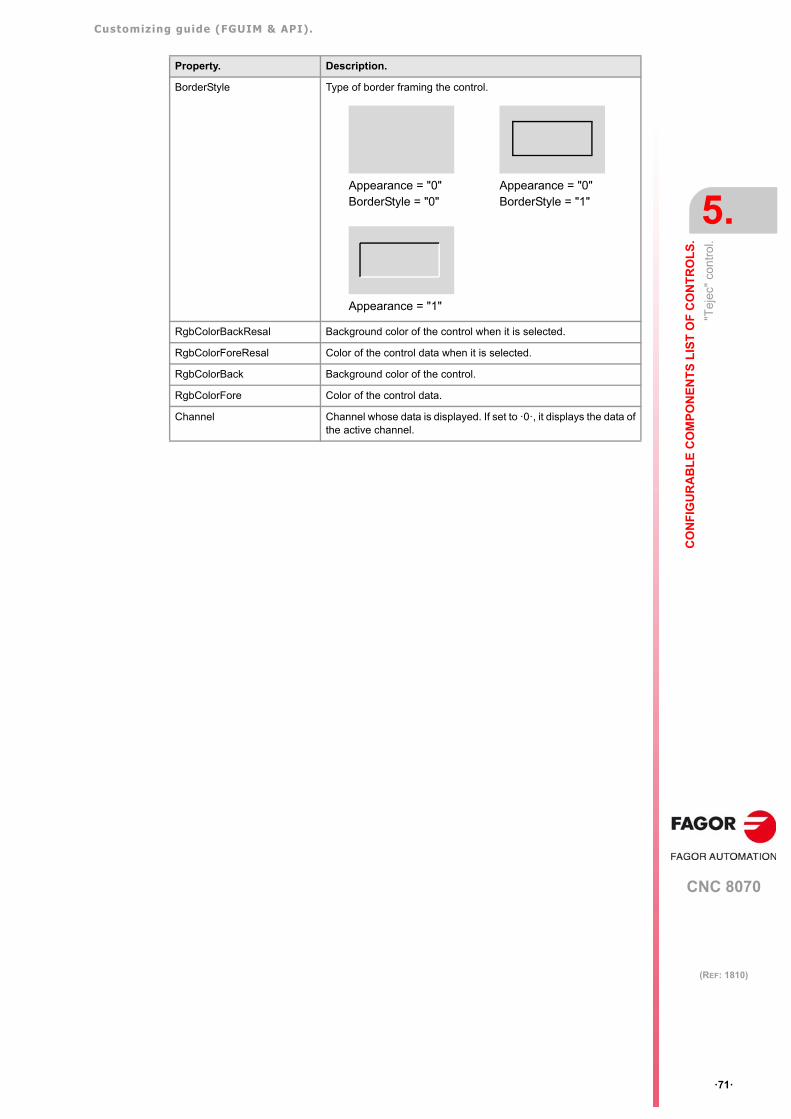
Customizing guide (FGUIM & API).
CNC 8070
CO
NF
IGU
RA
BL
E C
OM
PO
NE
NT
S L
IST
OF
CO
NT
RO
LS
.
5.
"Tej
ec"
cont
rol.
·71·
(REF: 1810)
BorderStyle Type of border framing the control.
RgbColorBackResal Background color of the control when it is selected.
RgbColorForeResal Color of the control data when it is selected.
RgbColorBack Background color of the control.
RgbColorFore Color of the control data.
Channel Channel whose data is displayed. If set to ·0·, it displays the data ofthe active channel.
Property. Description.
Appearance = "0"BorderStyle = "0"
Appearance = "0"BorderStyle = "1"
Appearance = "1"
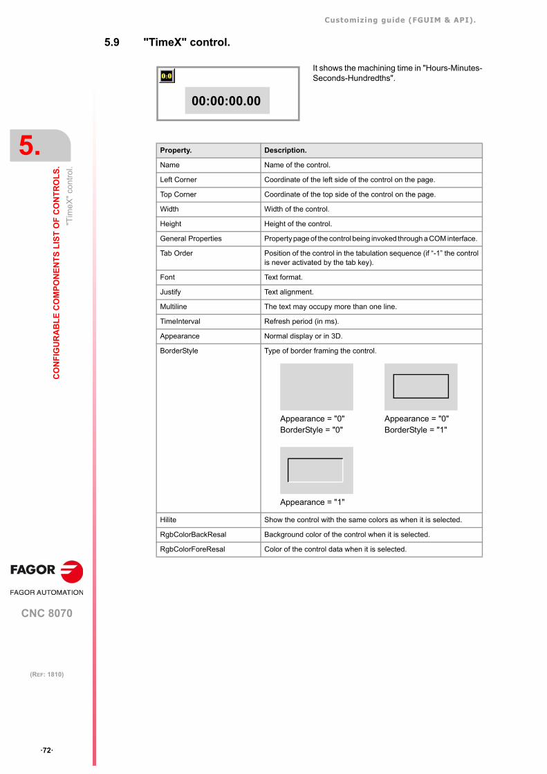
Customizing guide (FGUIM & API).
CNC 8070
5.
CO
NF
IGU
RA
BL
E C
OM
PO
NE
NT
S L
IST
OF
CO
NT
RO
LS
.
"Tim
eX"
cont
rol.
·72·
(REF: 1810)
5.9 "TimeX" control.
It shows the machining time in "Hours-Minutes-Seconds-Hundredths".
00:00:00.00
Property. Description.
Name Name of the control.
Left Corner Coordinate of the left side of the control on the page.
Top Corner Coordinate of the top side of the control on the page.
Width Width of the control.
Height Height of the control.
General Properties Property page of the control being invoked through a COM interface.
Tab Order Position of the control in the tabulation sequence (if “-1” the controlis never activated by the tab key).
Font Text format.
Justify Text alignment.
Multiline The text may occupy more than one line.
TimeInterval Refresh period (in ms).
Appearance Normal display or in 3D.
BorderStyle Type of border framing the control.
Hilite Show the control with the same colors as when it is selected.
RgbColorBackResal Background color of the control when it is selected.
RgbColorForeResal Color of the control data when it is selected.
Appearance = "0"BorderStyle = "0"
Appearance = "0"BorderStyle = "1"
Appearance = "1"
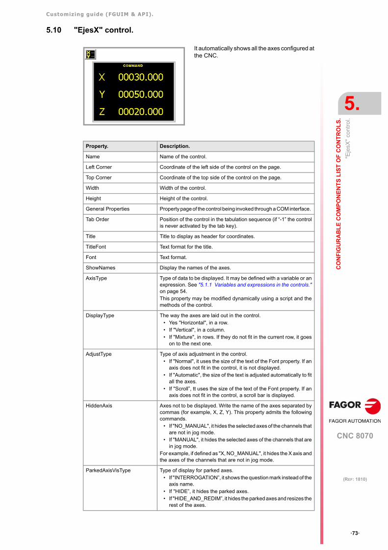
Customizing guide (FGUIM & API).
CNC 8070
CO
NF
IGU
RA
BL
E C
OM
PO
NE
NT
S L
IST
OF
CO
NT
RO
LS
.
5.
"Eje
sX"
cont
rol.
·73·
(REF: 1810)
5.10 "EjesX" control.
It automatically shows all the axes configured atthe CNC.
Property. Description.
Name Name of the control.
Left Corner Coordinate of the left side of the control on the page.
Top Corner Coordinate of the top side of the control on the page.
Width Width of the control.
Height Height of the control.
General Properties Property page of the control being invoked through a COM interface.
Tab Order Position of the control in the tabulation sequence (if “-1” the controlis never activated by the tab key).
Title Title to display as header for coordinates.
TitleFont Text format for the title.
Font Text format.
ShowNames Display the names of the axes.
AxisType Type of data to be displayed. It may be defined with a variable or anexpression. See "5.1.1 Variables and expressions in the controls."on page 54. This property may be modified dynamically using a script and themethods of the control.
DisplayType The way the axes are laid out in the control. • Yes "Horizontal", in a row.• If "Vertical", in a column.• If "Mixture", in rows. If they do not fit in the current row, it goes
on to the next one.
AdjustType Type of axis adjustment in the control. • If "Normal", it uses the size of the text of the Font property. If an
axis does not fit in the control, it is not displayed.• If "Automatic", the size of the text is adjusted automatically to fit
all the axes.• If "Scroll”, tt uses the size of the text of the Font property. If an
axis does not fit in the control, a scroll bar is displayed.
HiddenAxis Axes not to be displayed. Write the name of the axes separated bycommas (for example, X, Z, Y). This property admits the followingcommands.
• If "NO_MANUAL", it hides the selected axes of the channels thatare not in jog mode.
• If "MANUAL", it hides the selected axes of the channels that arein jog mode.
For example, if defined as "X, NO_MANUAL", it hides the X axis andthe axes of the channels that are not in jog mode.
ParkedAxisVisType Type of display for parked axes. • If "INTERROGATION”, it shows the question mark instead of the
axis name.• If "HIDE”, it hides the parked axes.• If "HIDE_AND_REDIM”, it hides the parked axes and resizes the
rest of the axes.
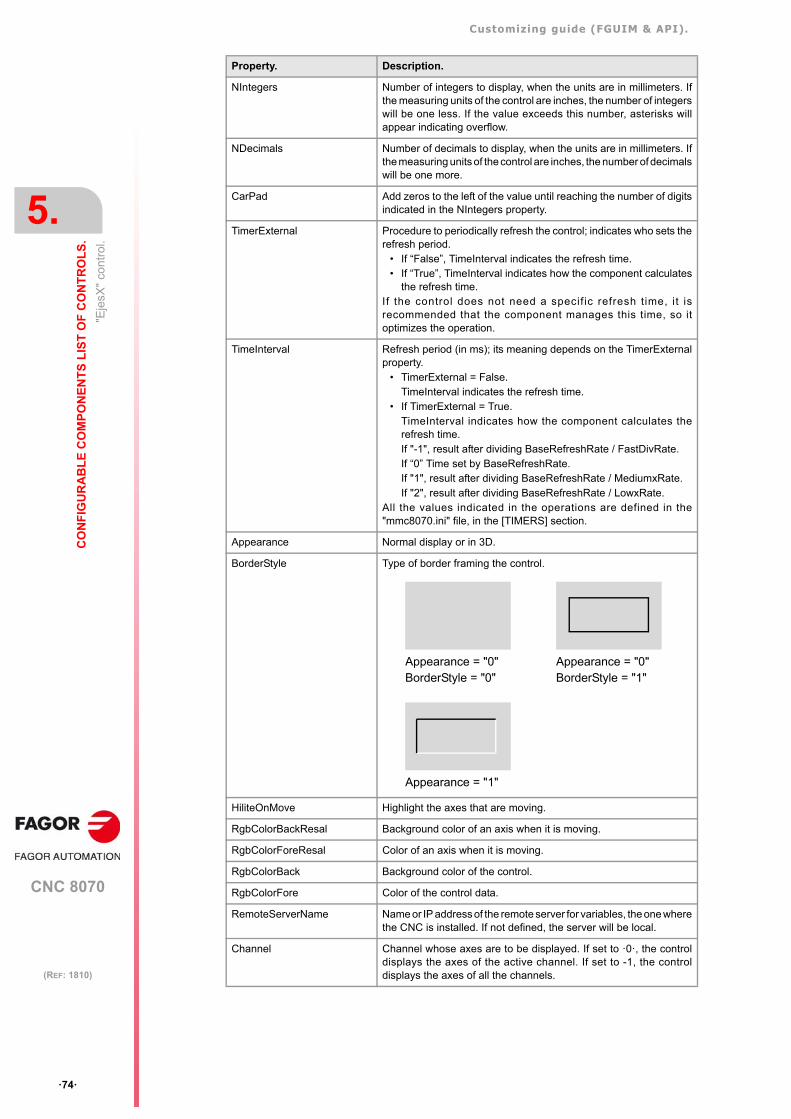
Customizing guide (FGUIM & API).
CNC 8070
5.
CO
NF
IGU
RA
BL
E C
OM
PO
NE
NT
S L
IST
OF
CO
NT
RO
LS
.
"Eje
sX"
cont
rol.
·74·
(REF: 1810)
NIntegers Number of integers to display, when the units are in millimeters. Ifthe measuring units of the control are inches, the number of integerswill be one less. If the value exceeds this number, asterisks willappear indicating overflow.
NDecimals Number of decimals to display, when the units are in millimeters. Ifthe measuring units of the control are inches, the number of decimalswill be one more.
CarPad Add zeros to the left of the value until reaching the number of digitsindicated in the NIntegers property.
TimerExternal Procedure to periodically refresh the control; indicates who sets therefresh period.
• If “False”, TimeInterval indicates the refresh time.• If “True”, TimeInterval indicates how the component calculates
the refresh time.If the control does not need a specif ic refresh time, it isrecommended that the component manages this time, so itoptimizes the operation.
TimeInterval Refresh period (in ms); its meaning depends on the TimerExternalproperty.
• TimerExternal = False.TimeInterval indicates the refresh time.
• If TimerExternal = True.TimeInterval indicates how the component calculates therefresh time.If "-1", result after dividing BaseRefreshRate / FastDivRate.If “0” Time set by BaseRefreshRate.If "1", result after dividing BaseRefreshRate / MediumxRate.If "2", result after dividing BaseRefreshRate / LowxRate.
All the values indicated in the operations are defined in the"mmc8070.ini" file, in the [TIMERS] section.
Appearance Normal display or in 3D.
BorderStyle Type of border framing the control.
HiliteOnMove Highlight the axes that are moving.
RgbColorBackResal Background color of an axis when it is moving.
RgbColorForeResal Color of an axis when it is moving.
RgbColorBack Background color of the control.
RgbColorFore Color of the control data.
RemoteServerName Name or IP address of the remote server for variables, the one wherethe CNC is installed. If not defined, the server will be local.
Channel Channel whose axes are to be displayed. If set to ·0·, the controldisplays the axes of the active channel. If set to -1, the controldisplays the axes of all the channels.
Property. Description.
Appearance = "0"BorderStyle = "0"
Appearance = "0"BorderStyle = "1"
Appearance = "1"
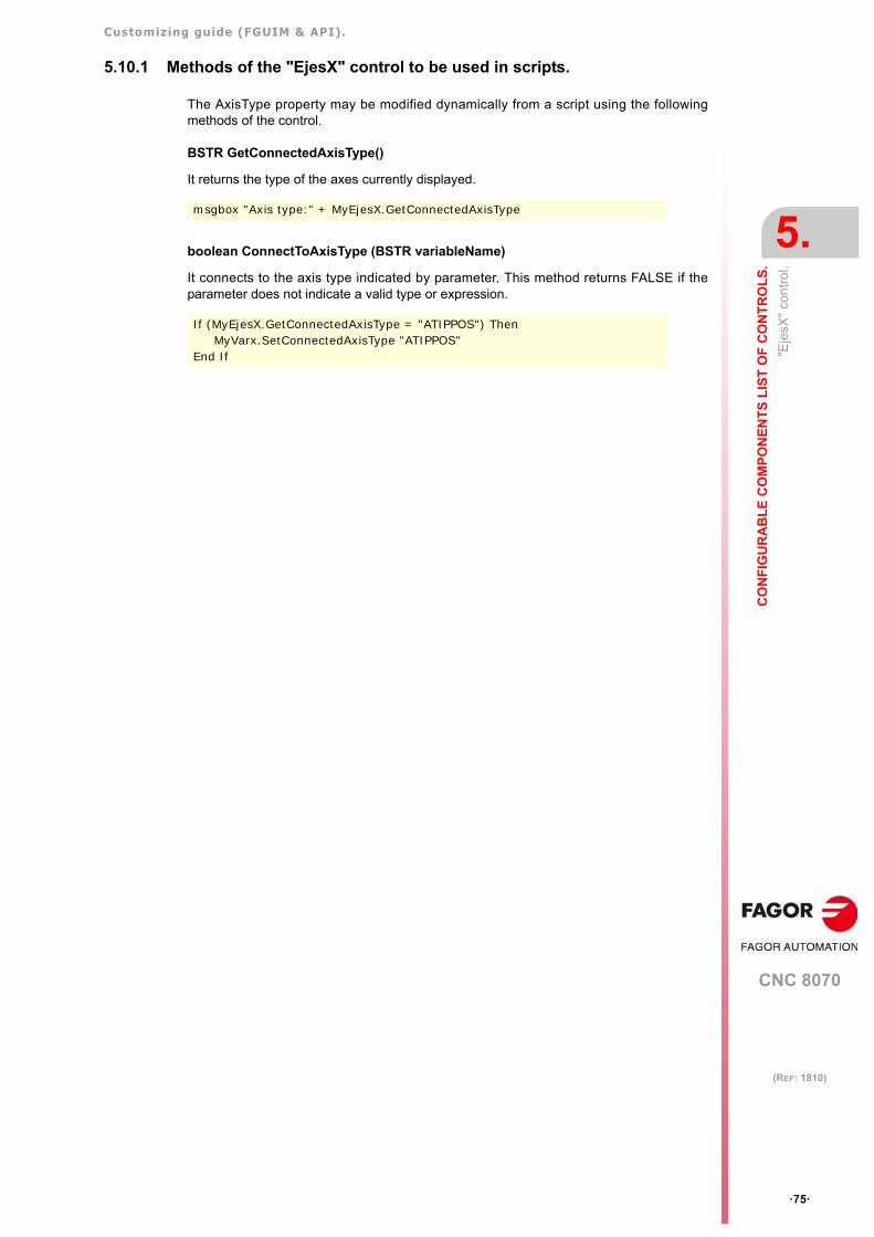
Customizing guide (FGUIM & API).
CNC 8070
CO
NF
IGU
RA
BL
E C
OM
PO
NE
NT
S L
IST
OF
CO
NT
RO
LS
.
5.
"Eje
sX"
cont
rol.
·75·
(REF: 1810)
5.10.1 Methods of the "EjesX" control to be used in scripts.
The AxisType property may be modified dynamically from a script using the followingmethods of the control.
BSTR GetConnectedAxisType()
It returns the type of the axes currently displayed.
boolean ConnectToAxisType (BSTR variableName)
It connects to the axis type indicated by parameter. This method returns FALSE if theparameter does not indicate a valid type or expression.
msgbox "Axis type:" + MyEjesX.GetConnectedAxisType
If (MyEjesX.GetConnectedAxisType = "ATIPPOS") Then MyVarx.SetConnectedAxisType "ATIPPOS"
End If
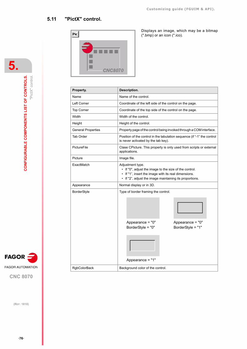
Customizing guide (FGUIM & API).
CNC 8070
5.
CO
NF
IGU
RA
BL
E C
OM
PO
NE
NT
S L
IST
OF
CO
NT
RO
LS
.
"Pic
tX"
cont
rol.
·76·
(REF: 1810)
5.11 "PictX" control.
Displays an image, which may be a bitmap(*.bmp) or an icon (*.ico).
Property. Description.
Name Name of the control.
Left Corner Coordinate of the left side of the control on the page.
Top Corner Coordinate of the top side of the control on the page.
Width Width of the control.
Height Height of the control.
General Properties Property page of the control being invoked through a COM interface.
Tab Order Position of the control in the tabulation sequence (if “-1” the controlis never activated by the tab key).
PictureFile Clase CPicture. This property is only used from scripts or externalapplications.
Picture Image file.
ExactMatch Adjustment type. • If "0", adjust the image to the size of the control. • If "1”, insert the image with its real dimensions.• If "2”, adjust the image maintaining its proportions.
Appearance Normal display or in 3D.
BorderStyle Type of border framing the control.
RgbColorBack Background color of the control.
Appearance = "0"BorderStyle = "0"
Appearance = "0"BorderStyle = "1"
Appearance = "1"
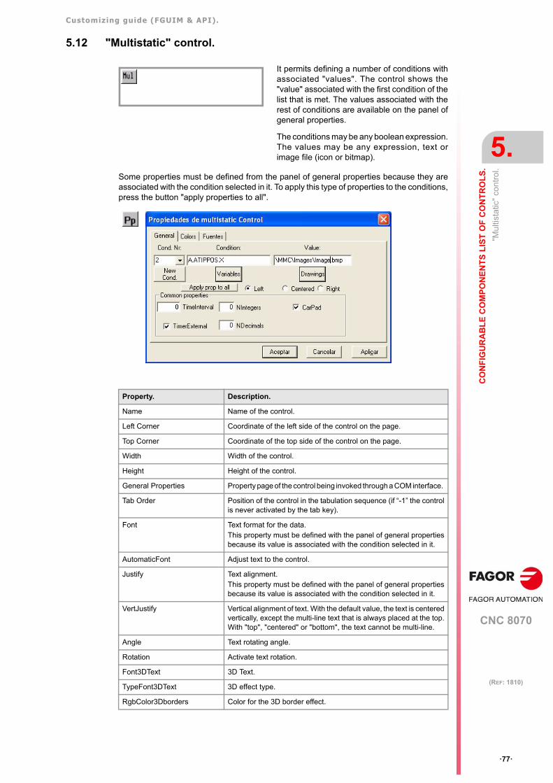
Customizing guide (FGUIM & API).
CNC 8070
CO
NF
IGU
RA
BL
E C
OM
PO
NE
NT
S L
IST
OF
CO
NT
RO
LS
.
5.
"Mul
tista
tic"
cont
rol.
·77·
(REF: 1810)
5.12 "Multistatic" control.
Some properties must be defined from the panel of general properties because they areassociated with the condition selected in it. To apply this type of properties to the conditions,press the button "apply properties to all".
It permits defining a number of conditions withassociated "values". The control shows the"value" associated with the first condition of thelist that is met. The values associated with therest of conditions are available on the panel ofgeneral properties.
The conditions may be any boolean expression.The values may be any expression, text orimage file (icon or bitmap).
Property. Description.
Name Name of the control.
Left Corner Coordinate of the left side of the control on the page.
Top Corner Coordinate of the top side of the control on the page.
Width Width of the control.
Height Height of the control.
General Properties Property page of the control being invoked through a COM interface.
Tab Order Position of the control in the tabulation sequence (if “-1” the controlis never activated by the tab key).
Font Text format for the data.This property must be defined with the panel of general propertiesbecause its value is associated with the condition selected in it.
AutomaticFont Adjust text to the control.
Justify Text alignment. This property must be defined with the panel of general propertiesbecause its value is associated with the condition selected in it.
VertJustify Vertical alignment of text. With the default value, the text is centeredvertically, except the multi-line text that is always placed at the top.With "top", "centered" or "bottom", the text cannot be multi-line.
Angle Text rotating angle.
Rotation Activate text rotation.
Font3DText 3D Text.
TypeFont3DText 3D effect type.
RgbColor3Dborders Color for the 3D border effect.
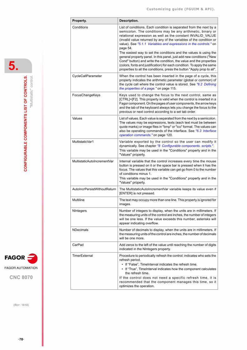
Customizing guide (FGUIM & API).
CNC 8070
5.
CO
NF
IGU
RA
BL
E C
OM
PO
NE
NT
S L
IST
OF
CO
NT
RO
LS
.
"Mul
tista
tic"
cont
rol.
·78·
(REF: 1810)
Conditions List of conditions. Each condition is separated from the next by asemicolon. The conditions may be any arithmetic, binary orrelational expression as well as the constant INVALID_VALUE(invalid value returned by any of the variables of the condition orvalue). See "5.1.1 Variables and expressions in the controls." onpage 54.The easiest way to set the conditions and the values is using thegeneral property panel. In this panel, just add new conditions ("NewCond" button) and write the condition, the value and the properties(colors, fonts and justification) for each condition. To apply the sameproperties to all the conditions, press the button "Apply prop to all".
CycleCallParameter When the control has been inserted in the page of a cycle, thisproperty indicates the arithmetic parameter (global or common) ofthe cycle call where the control value is stored. See "6.2 Definingthe properties of a page." on page 115.
FocusChangeKeys Keys used to change the focus to the next control, same as[CTRL]+[F2]. This property is valid when the control is inserted in aFagor component. On the pages of user components, the arrow keysand the tab of the keyboard always lets you change the focus to theprevious or next control according to a set tab order.
Values List of values. Each value is separated from the next by a semicolon.The values may be expressions, texts (each text must be betweenquote marks) or image files in "bmp" or "ico" format. The values canalso be operating commands of the interface. See "6.3 Interfaceoperation commands." on page 120.
MultistaticVar1 Variable exported by the control so the user can modify itdynamically. See chapter "8 Configurable components. scripts.".This variable may be used in the "Conditions" property and in the"Values" property.
MultistaticAutoIncrementVar Internal variable that the control increases every time the mousebutton is pressed on it or the space bar is pressed when it has thefocus. The values that this variable can get go from 0 to the numberof conditions minus 1. This variable may be used in the "Conditions" property and in the"Values" property.
AutoIncrPersistWithoutReturn The MultistaticAutoIncrementVar variable keeps its value even if[ENTER] is not pressed.
Multiline The text may occupy more than one line. This property is ignored forimages.
NIntegers Number of integers to display, when the units are in millimeters. Ifthe measuring units of the control are inches, the number of integerswill be one less. If the value exceeds this number, asterisks willappear indicating overflow.
NDecimals Number of decimals to display, when the units are in millimeters. Ifthe measuring units of the control are inches, the number of decimalswill be one more.
CarPad Add zeros to the left of the value until reaching the number of digitsindicated in the NIntegers property.
TimerExternal Procedure to periodically refresh the control; indicates who sets therefresh period.
• If “False”, TimeInterval indicates the refresh time.• If “True”, TimeInterval indicates how the component calculates
the refresh time.If the control does not need a specif ic refresh time, it isrecommended that the component manages this time, so itoptimizes the operation.
Property. Description.
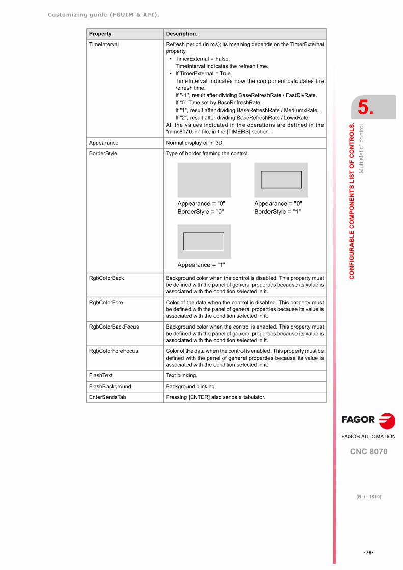
Customizing guide (FGUIM & API).
CNC 8070
CO
NF
IGU
RA
BL
E C
OM
PO
NE
NT
S L
IST
OF
CO
NT
RO
LS
.
5.
"Mul
tista
tic"
cont
rol.
·79·
(REF: 1810)
TimeInterval Refresh period (in ms); its meaning depends on the TimerExternalproperty.
• TimerExternal = False.TimeInterval indicates the refresh time.
• If TimerExternal = True.TimeInterval indicates how the component calculates therefresh time.If "-1", result after dividing BaseRefreshRate / FastDivRate.If “0” Time set by BaseRefreshRate.If "1", result after dividing BaseRefreshRate / MediumxRate.If "2", result after dividing BaseRefreshRate / LowxRate.
All the values indicated in the operations are defined in the"mmc8070.ini" file, in the [TIMERS] section.
Appearance Normal display or in 3D.
BorderStyle Type of border framing the control.
RgbColorBack Background color when the control is disabled. This property mustbe defined with the panel of general properties because its value isassociated with the condition selected in it.
RgbColorFore Color of the data when the control is disabled. This property mustbe defined with the panel of general properties because its value isassociated with the condition selected in it.
RgbColorBackFocus Background color when the control is enabled. This property mustbe defined with the panel of general properties because its value isassociated with the condition selected in it.
RgbColorForeFocus Color of the data when the control is enabled. This property must bedefined with the panel of general properties because its value isassociated with the condition selected in it.
FlashText Text blinking.
FlashBackground Background blinking.
EnterSendsTab Pressing [ENTER] also sends a tabulator.
Property. Description.
Appearance = "0"BorderStyle = "0"
Appearance = "0"BorderStyle = "1"
Appearance = "1"
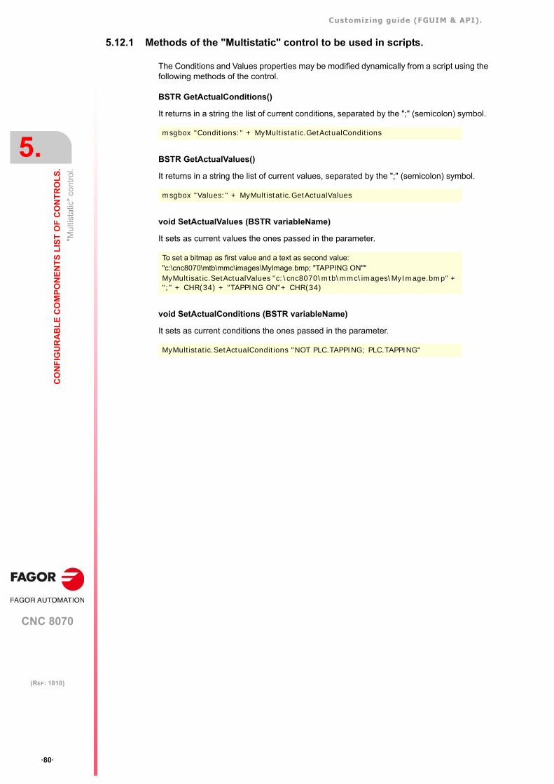
Customizing guide (FGUIM & API).
CNC 8070
5.
CO
NF
IGU
RA
BL
E C
OM
PO
NE
NT
S L
IST
OF
CO
NT
RO
LS
.
"Mul
tista
tic"
cont
rol.
·80·
(REF: 1810)
5.12.1 Methods of the "Multistatic" control to be used in scripts.
The Conditions and Values properties may be modified dynamically from a script using thefollowing methods of the control.
BSTR GetActualConditions()
It returns in a string the list of current conditions, separated by the ";" (semicolon) symbol.
BSTR GetActualValues()
It returns in a string the list of current values, separated by the ";" (semicolon) symbol.
void SetActualValues (BSTR variableName)
It sets as current values the ones passed in the parameter.
void SetActualConditions (BSTR variableName)
It sets as current conditions the ones passed in the parameter.
msgbox "Conditions:" + MyMultistatic.GetActualConditions
msgbox "Values:" + MyMultistatic.GetActualValues
To set a bitmap as first value and a text as second value:"c:\cnc8070\mtb\mmc\images\MyImage.bmp; "TAPPING ON"" MyMultisatic.SetActualValues "c:\cnc8070\mtb\mmc\images\MyImage.bmp" + ";" + CHR(34) + "TAPPING ON"+ CHR(34)
MyMultistatic.SetActualConditions "NOT PLC.TAPPING; PLC.TAPPING"
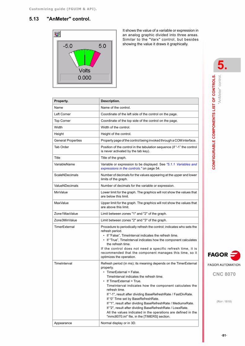
Customizing guide (FGUIM & API).
CNC 8070
CO
NF
IGU
RA
BL
E C
OM
PO
NE
NT
S L
IST
OF
CO
NT
RO
LS
.
5.
"AnM
eter
" co
ntro
l.
·81·
(REF: 1810)
5.13 "AnMeter" control.
It shows the value of a variable or expression inan analog graphic divided into three areas.Similar to the "Varx" control, but besidesshowing the value it draws it graphically.
Property. Description.
Name Name of the control.
Left Corner Coordinate of the left side of the control on the page.
Top Corner Coordinate of the top side of the control on the page.
Width Width of the control.
Height Height of the control.
General Properties Property page of the control being invoked through a COM interface.
Tab Order Position of the control in the tabulation sequence (if “-1” the controlis never activated by the tab key).
Title Title of the graph.
VariableName Variable or expression to be displayed. See "5.1.1 Variables andexpressions in the controls." on page 54.
ScaleNDecimals Number of decimals for the values appearing at the upper and lowerlimits of the graph.
ValueNDecimals Number of decimals for the variable or expression.
MinValue Lower limit for the graph. The graphics will not show the values thatare below this limit.
MaxValue Upper limit for the graph. The graphics will not show the values thatare above this limit.
Zone1MaxValue Limit between zones "1" and "2" of the graph.
Zone3MinValue Limit between zones "2" and "3" of the graph.
TimerExternal Procedure to periodically refresh the control; indicates who sets therefresh period.
• If “False”, TimeInterval indicates the refresh time.• If “True”, TimeInterval indicates how the component calculates
the refresh time.If the control does not need a specif ic refresh time, it isrecommended that the component manages this time, so itoptimizes the operation.
TimeInterval Refresh period (in ms); its meaning depends on the TimerExternalproperty.
• TimerExternal = False.TimeInterval indicates the refresh time.
• If TimerExternal = True.TimeInterval indicates how the component calculates therefresh time.If "-1", result after dividing BaseRefreshRate / FastDivRate.If “0” Time set by BaseRefreshRate.If "1", result after dividing BaseRefreshRate / MediumxRate.If "2", result after dividing BaseRefreshRate / LowxRate.All the values indicated in the operations are defined in the"mmc8070.ini" file, in the [TIMERS] section.
Appearance Normal display or in 3D.
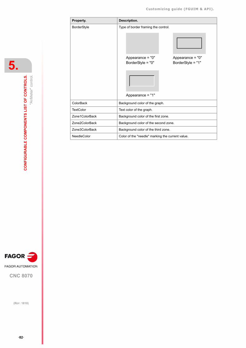
Customizing guide (FGUIM & API).
CNC 8070
5.
CO
NF
IGU
RA
BL
E C
OM
PO
NE
NT
S L
IST
OF
CO
NT
RO
LS
.
"AnM
eter
" co
ntro
l.
·82·
(REF: 1810)
BorderStyle Type of border framing the control.
ColorBack Background color of the graph.
TextColor Text color of the graph.
Zone1ColorBack Background color of the first zone.
Zone2ColorBack Background color of the second zone.
Zone3ColorBack Background color of the third zone.
NeedleColor Color of the "needle" marking the current value.
Property. Description.
Appearance = "0"BorderStyle = "0"
Appearance = "0"BorderStyle = "1"
Appearance = "1"
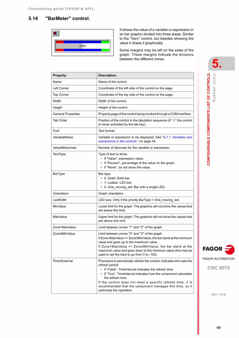
Customizing guide (FGUIM & API).
CNC 8070
CO
NF
IGU
RA
BL
E C
OM
PO
NE
NT
S L
IST
OF
CO
NT
RO
LS
.
5.
"Bar
Met
er"
cont
rol.
·83·
(REF: 1810)
5.14 "BarMeter" control.
It shows the value of a variable or expression inan bar graphic divided into three areas. Similarto the "Varx" control, but besides showing thevalue it draws it graphically.
Some margins may be left on the sides of thegraph. These margins indicate the divisionsbetween the different zones.
Property. Description.
Name Name of the control.
Left Corner Coordinate of the left side of the control on the page.
Top Corner Coordinate of the top side of the control on the page.
Width Width of the control.
Height Height of the control.
General Properties Property page of the control being invoked through a COM interface.
Tab Order Position of the control in the tabulation sequence (if “-1” the controlis never activated by the tab key).
Font Text format.
VariableName Variable or expression to be displayed. See "5.1.1 Variables andexpressions in the controls." on page 54.
ValueNDecimals Number of decimals for the variable or expression.
TextType Type of text to show. • If "Value", expression value.• If "Percent”, percentage of the value on the graph.• If "None", do not show the value.
BarType Bar type. • 0- Solid: Solid bar.• 1- Ledbar: LED bar. • 2- One_moving_led: Bar with a single LED.
Orientation Graph orientation.
LedWidth LED size. Only if the priority BarType = One_moving_led.
MinValue Lower limit for the graph. The graphics will not show the values thatare below this limit.
MaxValue Upper limit for the graph. The graphics will not show the values thatare above this limit.
Zone1MaxValue Limit between zones "1" and "2" of the graph.
Zone3MinValue Limit between zones "2" and "3" of the graph.If Zone1MaxValue <= Zone3MinValue, the bar starts at the minimumvalue and goes up to the maximum value.If Zone1MaxValue >= Zone3MinValue, the bar starts at themaximum value and goes down to the minimum value (this may beused to set the bars to go from 0 to -100).
TimerExternal Procedure to periodically refresh the control; indicates who sets therefresh period.
• If “False”, TimeInterval indicates the refresh time.• If “True”, TimeInterval indicates how the component calculates
the refresh time.If the control does not need a specif ic refresh time, it isrecommended that the component manages this time, so itoptimizes the operation.
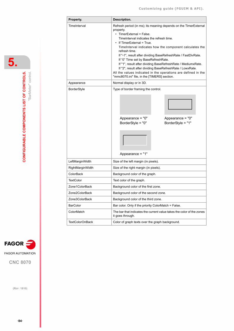
Customizing guide (FGUIM & API).
CNC 8070
5.
CO
NF
IGU
RA
BL
E C
OM
PO
NE
NT
S L
IST
OF
CO
NT
RO
LS
.
"Bar
Met
er"
cont
rol.
·84·
(REF: 1810)
TimeInterval Refresh period (in ms); its meaning depends on the TimerExternalproperty.
• TimerExternal = False.TimeInterval indicates the refresh time.
• If TimerExternal = True.TimeInterval indicates how the component calculates therefresh time.If "-1", result after dividing BaseRefreshRate / FastDivRate.If “0” Time set by BaseRefreshRate.If "1", result after dividing BaseRefreshRate / MediumxRate.If "2", result after dividing BaseRefreshRate / LowxRate.
All the values indicated in the operations are defined in the"mmc8070.ini" file, in the [TIMERS] section.
Appearance Normal display or in 3D.
BorderStyle Type of border framing the control.
LeftMarginWidth Size of the left margin (in pixels).
RightMarginWidth Size of the right margin (in pixels).
ColorBack Background color of the graph.
TextColor Text color of the graph.
Zone1ColorBack Background color of the first zone.
Zone2ColorBack Background color of the second zone.
Zone3ColorBack Background color of the third zone.
BarColor Bar color. Only if the priority ColorMatch = False.
ColorMatch The bar that indicates the current value takes the color of the zonesit goes through.
TextColorOnBack Color of graph texts over the graph background.
Property. Description.
Appearance = "0"BorderStyle = "0"
Appearance = "0"BorderStyle = "1"
Appearance = "1"
Customizing guide (FGUIM & API).
CNC 8070
CO
NF
IGU
RA
BL
E C
OM
PO
NE
NT
S L
IST
OF
CO
NT
RO
LS
.
5.
"Avi
Ctr
l" c
ontr
ol.
·85·
(REF: 1810)
5.15 "AviCtrl" control.
It shows a video.
Property. Description.
Name Name of the control.
Left Corner Coordinate of the left side of the control on the page.
Top Corner Coordinate of the top side of the control on the page.
Width Width of the control.
Height Height of the control.
General Properties Property page of the control being invoked through a COM interface.
Tab Order Position of the control in the tabulation sequence (if “-1” the controlis never activated by the tab key).
AviFile Name of the video to display. The video must be in "AVI" format.
StretchAvi Adjust the size of the video to the size of the control.
Speed Video speed (Low, Normal, High).
ColorBack Background color of the control. It is only taken into account onvideos with a transparent background.
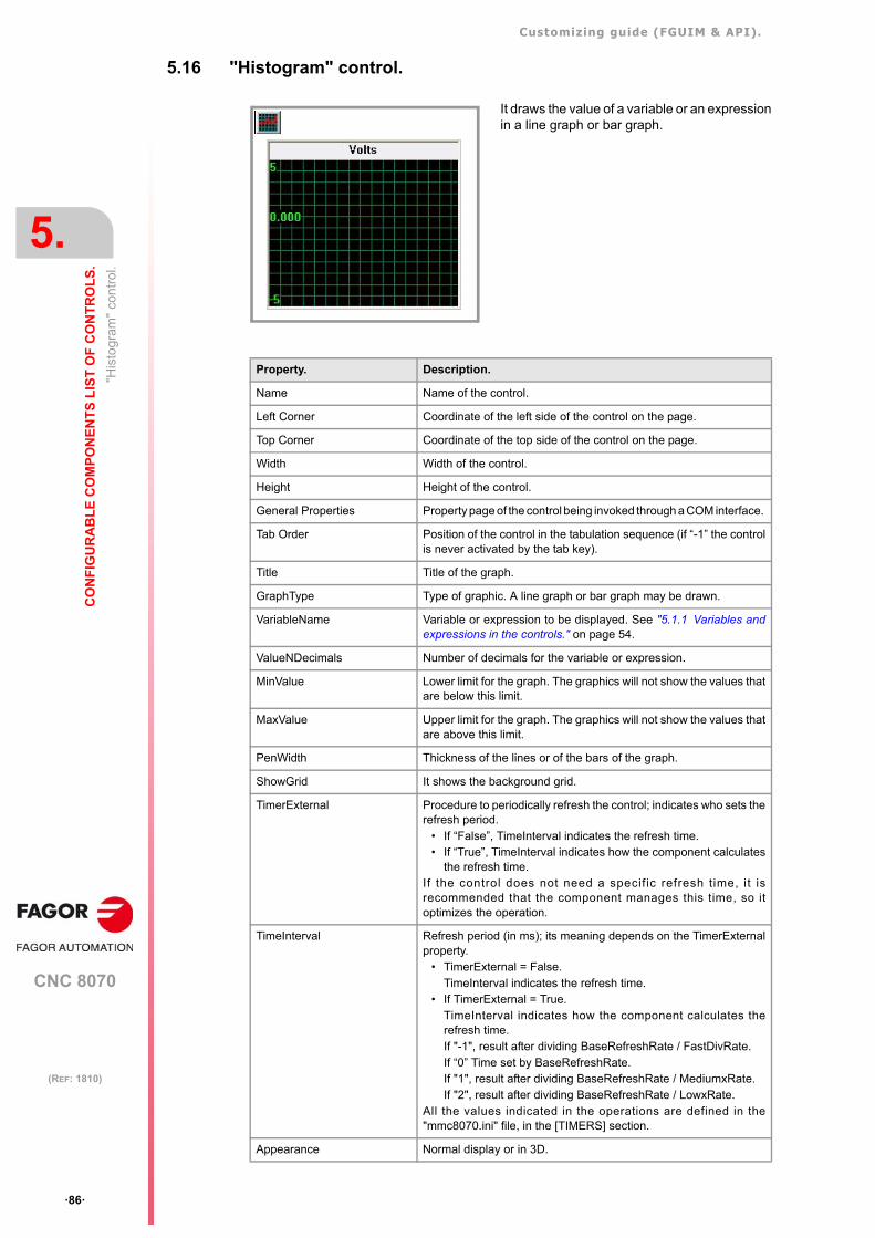
Customizing guide (FGUIM & API).
CNC 8070
5.
CO
NF
IGU
RA
BL
E C
OM
PO
NE
NT
S L
IST
OF
CO
NT
RO
LS
.
"His
togr
am"
cont
rol.
·86·
(REF: 1810)
5.16 "Histogram" control.
It draws the value of a variable or an expressionin a line graph or bar graph.
Property. Description.
Name Name of the control.
Left Corner Coordinate of the left side of the control on the page.
Top Corner Coordinate of the top side of the control on the page.
Width Width of the control.
Height Height of the control.
General Properties Property page of the control being invoked through a COM interface.
Tab Order Position of the control in the tabulation sequence (if “-1” the controlis never activated by the tab key).
Title Title of the graph.
GraphType Type of graphic. A line graph or bar graph may be drawn.
VariableName Variable or expression to be displayed. See "5.1.1 Variables andexpressions in the controls." on page 54.
ValueNDecimals Number of decimals for the variable or expression.
MinValue Lower limit for the graph. The graphics will not show the values thatare below this limit.
MaxValue Upper limit for the graph. The graphics will not show the values thatare above this limit.
PenWidth Thickness of the lines or of the bars of the graph.
ShowGrid It shows the background grid.
TimerExternal Procedure to periodically refresh the control; indicates who sets therefresh period.
• If “False”, TimeInterval indicates the refresh time.• If “True”, TimeInterval indicates how the component calculates
the refresh time.If the control does not need a specif ic refresh time, it isrecommended that the component manages this time, so itoptimizes the operation.
TimeInterval Refresh period (in ms); its meaning depends on the TimerExternalproperty.
• TimerExternal = False.TimeInterval indicates the refresh time.
• If TimerExternal = True.TimeInterval indicates how the component calculates therefresh time.If "-1", result after dividing BaseRefreshRate / FastDivRate.If “0” Time set by BaseRefreshRate.If "1", result after dividing BaseRefreshRate / MediumxRate.If "2", result after dividing BaseRefreshRate / LowxRate.
All the values indicated in the operations are defined in the"mmc8070.ini" file, in the [TIMERS] section.
Appearance Normal display or in 3D.
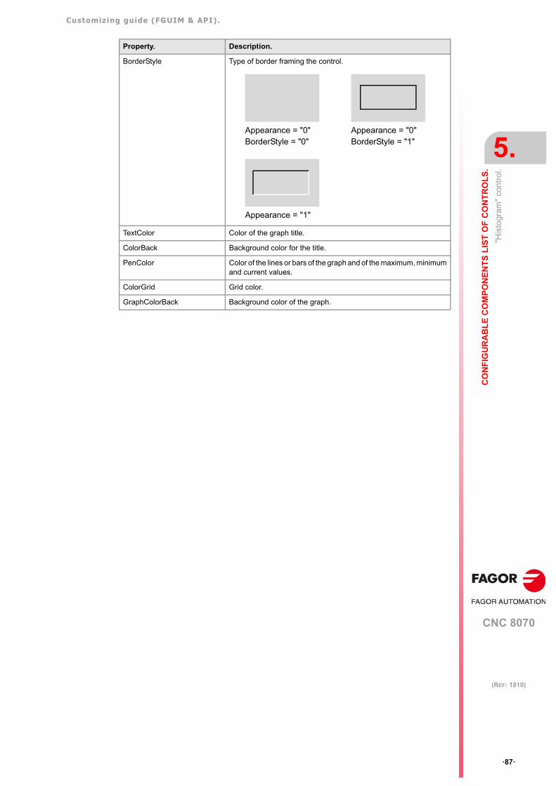
Customizing guide (FGUIM & API).
CNC 8070
CO
NF
IGU
RA
BL
E C
OM
PO
NE
NT
S L
IST
OF
CO
NT
RO
LS
.
5.
"His
togr
am"
cont
rol.
·87·
(REF: 1810)
BorderStyle Type of border framing the control.
TextColor Color of the graph title.
ColorBack Background color for the title.
PenColor Color of the lines or bars of the graph and of the maximum, minimumand current values.
ColorGrid Grid color.
GraphColorBack Background color of the graph.
Property. Description.
Appearance = "0"BorderStyle = "0"
Appearance = "0"BorderStyle = "1"
Appearance = "1"
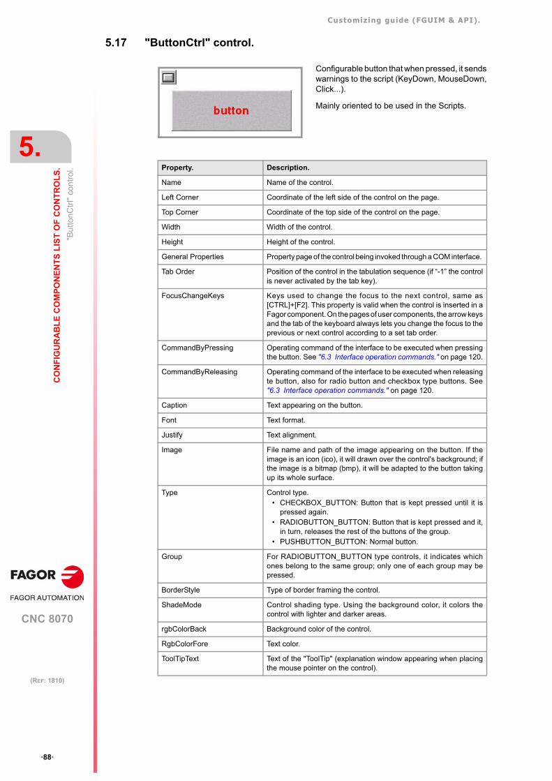
Customizing guide (FGUIM & API).
CNC 8070
5.
CO
NF
IGU
RA
BL
E C
OM
PO
NE
NT
S L
IST
OF
CO
NT
RO
LS
.
"But
tonC
trl"
con
trol
.
·88·
(REF: 1810)
5.17 "ButtonCtrl" control.
Configurable button that when pressed, it sendswarnings to the script (KeyDown, MouseDown,Click...).
Mainly oriented to be used in the Scripts.
Property. Description.
Name Name of the control.
Left Corner Coordinate of the left side of the control on the page.
Top Corner Coordinate of the top side of the control on the page.
Width Width of the control.
Height Height of the control.
General Properties Property page of the control being invoked through a COM interface.
Tab Order Position of the control in the tabulation sequence (if “-1” the controlis never activated by the tab key).
FocusChangeKeys Keys used to change the focus to the next control, same as[CTRL]+[F2]. This property is valid when the control is inserted in aFagor component. On the pages of user components, the arrow keysand the tab of the keyboard always lets you change the focus to theprevious or next control according to a set tab order.
CommandByPressing Operating command of the interface to be executed when pressingthe button. See "6.3 Interface operation commands." on page 120.
CommandByReleasing Operating command of the interface to be executed when releasingte button, also for radio button and checkbox type buttons. See"6.3 Interface operation commands." on page 120.
Caption Text appearing on the button.
Font Text format.
Justify Text alignment.
Image File name and path of the image appearing on the button. If theimage is an icon (ico), it will drawn over the control's background; ifthe image is a bitmap (bmp), it will be adapted to the button takingup its whole surface.
Type Control type. • CHECKBOX_BUTTON: Button that is kept pressed until it is
pressed again.• RADIOBUTTON_BUTTON: Button that is kept pressed and it,
in turn, releases the rest of the buttons of the group.• PUSHBUTTON_BUTTON: Normal button.
Group For RADIOBUTTON_BUTTON type controls, it indicates whichones belong to the same group; only one of each group may bepressed.
BorderStyle Type of border framing the control.
ShadeMode Control shading type. Using the background color, it colors thecontrol with lighter and darker areas.
rgbColorBack Background color of the control.
RgbColorFore Text color.
ToolTipText Text of the "ToolTip" (explanation window appearing when placingthe mouse pointer on the control).
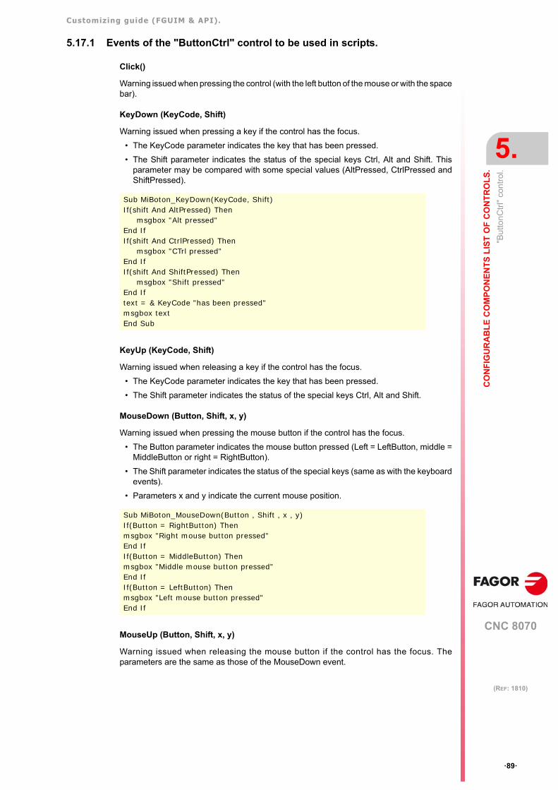
Customizing guide (FGUIM & API).
CNC 8070
CO
NF
IGU
RA
BL
E C
OM
PO
NE
NT
S L
IST
OF
CO
NT
RO
LS
.
5.
"But
tonC
trl"
con
trol
.
·89·
(REF: 1810)
5.17.1 Events of the "ButtonCtrl" control to be used in scripts.
Click()
Warning issued when pressing the control (with the left button of the mouse or with the spacebar).
KeyDown (KeyCode, Shift)
Warning issued when pressing a key if the control has the focus.
• The KeyCode parameter indicates the key that has been pressed.
• The Shift parameter indicates the status of the special keys Ctrl, Alt and Shift. Thisparameter may be compared with some special values (AltPressed, CtrlPressed andShiftPressed).
KeyUp (KeyCode, Shift)
Warning issued when releasing a key if the control has the focus.
• The KeyCode parameter indicates the key that has been pressed.
• The Shift parameter indicates the status of the special keys Ctrl, Alt and Shift.
MouseDown (Button, Shift, x, y)
Warning issued when pressing the mouse button if the control has the focus.
• The Button parameter indicates the mouse button pressed (Left = LeftButton, middle =MiddleButton or right = RightButton).
• The Shift parameter indicates the status of the special keys (same as with the keyboardevents).
• Parameters x and y indicate the current mouse position.
MouseUp (Button, Shift, x, y)
Warning issued when releasing the mouse button if the control has the focus. Theparameters are the same as those of the MouseDown event.
Sub MiBoton_KeyDown(KeyCode, Shift)If(shift And AltPressed) Then
msgbox "Alt pressed"End If If(shift And CtrlPressed) Then
msgbox "CTrl pressed"End If If(shift And ShiftPressed) Then
msgbox "Shift pressed"End If text = & KeyCode "has been pressed"msgbox textEnd Sub
Sub MiBoton_MouseDown(Button , Shift , x , y)If(Button = RightButton) Then msgbox "Right mouse button pressed"End IfIf(Button = MiddleButton) Then msgbox "Middle mouse button pressed"End IfIf(Button = LeftButton) Then msgbox "Left mouse button pressed"End If

Customizing guide (FGUIM & API).
CNC 8070
5.
CO
NF
IGU
RA
BL
E C
OM
PO
NE
NT
S L
IST
OF
CO
NT
RO
LS
.
"Edi
tX"
cont
rol.
·90·
(REF: 1810)
5.18 "EditX" control.
General purpose editor. For the user to entersmall texts.
Mainly oriented to be used in the Scripts.
Property. Description.
Name Name of the control.
Left Corner Coordinate of the left side of the control on the page.
Top Corner Coordinate of the top side of the control on the page.
Width Width of the control.
Height Height of the control.
General Properties Property page of the control being invoked through a COM interface.
Tab Order Position of the control in the tabulation sequence (if “-1” the controlis never activated by the tab key).
Text Text shown by default.
Font Text format for the data.
Multiline The text may occupy more than one line. For a MultiLine control,pressing ENTER inserts a new line. The control automatically showsthe vertical or horizontal scroll bars.
CycleCallParameter When the control has been inserted in the page of a cycle, thisproperty indicates the arithmetic parameter (global or common) ofthe cycle call where the control value is stored. See "6.2 Definingthe properties of a page." on page 115.
FocusChangeKeys Keys used to change the focus to the next control, same as[CTRL]+[F2]. This property is valid when the control is inserted in aFagor component. On the pages of user components, the arrow keysand the tab of the keyboard always lets you change the focus to theprevious or next control according to a set tab order.
StyleAlign Text alignment. • If 0, left align.• If 1, centered.• If 2, right align.
ReadOnly It determines whether the entered text is read-only or not. If so, newtext cannot be written in the control.
RejectEditAttemps It determines whether the control may be temporarily read-only. Thisproperty is oriented to be used from a script.
Numeric Numbers may be used.
Precision Numerical precision.
AllowDecimals Decimals may be used.
DecimalSymbol Symbol to identify the decimal part.
AllowNegatives Negative numbers may be used.
NegativesSymbol Symbol to identify the negative numbers.
Appearance Normal display or in 3D.
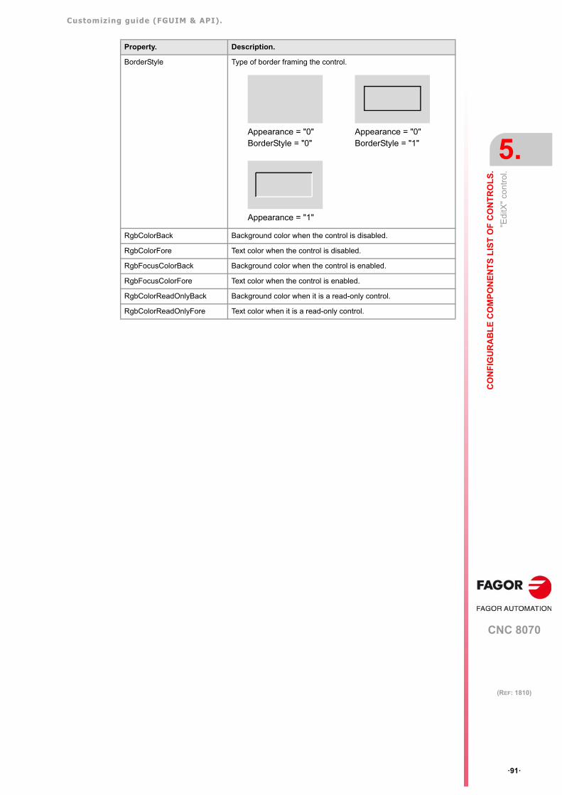
Customizing guide (FGUIM & API).
CNC 8070
CO
NF
IGU
RA
BL
E C
OM
PO
NE
NT
S L
IST
OF
CO
NT
RO
LS
.
5.
"Edi
tX"
cont
rol.
·91·
(REF: 1810)
BorderStyle Type of border framing the control.
RgbColorBack Background color when the control is disabled.
RgbColorFore Text color when the control is disabled.
RgbFocusColorBack Background color when the control is enabled.
RgbFocusColorFore Text color when the control is enabled.
RgbColorReadOnlyBack Background color when it is a read-only control.
RgbColorReadOnlyFore Text color when it is a read-only control.
Property. Description.
Appearance = "0"BorderStyle = "0"
Appearance = "0"BorderStyle = "1"
Appearance = "1"
Customizing guide (FGUIM & API).
CNC 8070
5.
CO
NF
IGU
RA
BL
E C
OM
PO
NE
NT
S L
IST
OF
CO
NT
RO
LS
.
"Edi
tX"
cont
rol.
·92·
(REF: 1810)
5.18.1 Methods of the "EditCtrl" control to be used in scripts.
Undo()
It undoes the last operation.
GetSet(long* pnStartChar, long* pnEndChar)
It returns in two variables the first and last character of the selected text, if there is one.
ReplaceSel(BSTR pText, long bCanUndo)
If a text has been selected, it is replaced by pText. It also indicates whether the operationcan be undone or not.
SetSel(long nStartChar, long nEndChar, long nNoScroll)
It selects a range of characters. This range goes from nStartChar to nEndChar. It alsoindicates whether the insertion pointer moves or not.
Clear()
Deletes the selected text, if there is one.
Copy()
It copies the selected text onto the clipboard.
Cut()
Copies the selected text onto the clipboard and deletes it from the editor.
Paste()
Copies the contents of the clipboard into the editor.
Customizing guide (FGUIM & API).
CNC 8070
CO
NF
IGU
RA
BL
E C
OM
PO
NE
NT
S L
IST
OF
CO
NT
RO
LS
.
5.
"Web
Cam
X"
cont
rol.
·93·
(REF: 1810)
5.19 "WebCamX" control.
It shows a video source usually coming from aWebCam.
Property. Description.
Name Name of the control.
Left Corner Coordinate of the left side of the control on the page.
Top Corner Coordinate of the top side of the control on the page.
Width Width of the control.
Height Height of the control.
General Properties Property page of the control being invoked through a COM interface.
Tab Order Position of the control in the tabulation sequence (if “-1” the controlis never activated by the tab key).
VideoSource Video source.• If 0, WebCam.• If 1, composite video.• If 2, TV tuner.• If 3, S_Video.
SquareRatio It indicates whether the video is adjusted to the control window(value =0), in which case the image may be deformed or it isdisplayed with its corresponding aspect ratio (value =1). To show the video with its aspect ration, it takes its smaller X and Ycoordinates and it shows the video in a square within the window.In this case the image is not deformed, but it may not take up thewhole window. In this area, it will display the background colordefined in the previous property.
FileCapturaImage Name and address of the path where the WebCam photos aresaved.
rgbColorBack Background color of the control.
Customizing guide (FGUIM & API).
CNC 8070
5.
CO
NF
IGU
RA
BL
E C
OM
PO
NE
NT
S L
IST
OF
CO
NT
RO
LS
.
"Web
Cam
X"
cont
rol.
·94·
(REF: 1810)
5.19.1 Functions of the "WebCamX" control to be used in scripts.
Start
It activates the video source.
Stop
It deactivates the video source
CaptureImage
It is possible to capture "photos" coming from the video source. Calling this function createsa BMP file with the name and path indicated in the FileCaptureImage property. If this functionhas not been initialized, it creates the file "C:\tmp\test.bmp".
It is up to the user when calling this function to change the name of the BMP; otherwise, thenext time this function is called, it will overwrite the previous BMP.
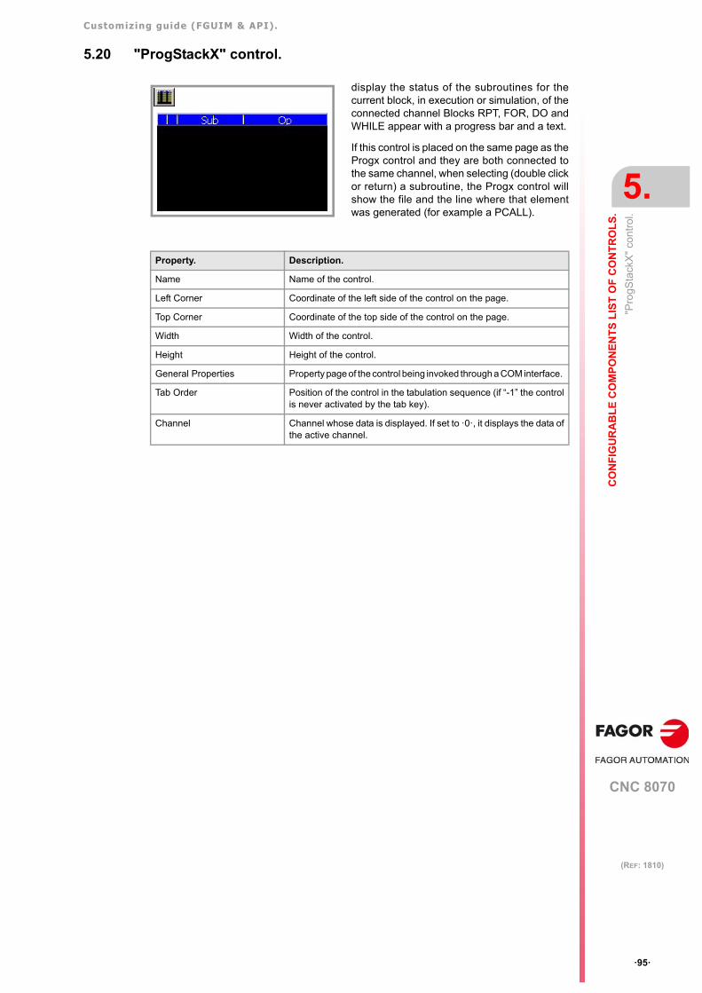
Customizing guide (FGUIM & API).
CNC 8070
CO
NF
IGU
RA
BL
E C
OM
PO
NE
NT
S L
IST
OF
CO
NT
RO
LS
.
5.
"Pro
gSta
ckX
" co
ntro
l.
·95·
(REF: 1810)
5.20 "ProgStackX" control.
display the status of the subroutines for thecurrent block, in execution or simulation, of theconnected channel Blocks RPT, FOR, DO andWHILE appear with a progress bar and a text.
If this control is placed on the same page as theProgx control and they are both connected tothe same channel, when selecting (double clickor return) a subroutine, the Progx control willshow the file and the line where that elementwas generated (for example a PCALL).
Property. Description.
Name Name of the control.
Left Corner Coordinate of the left side of the control on the page.
Top Corner Coordinate of the top side of the control on the page.
Width Width of the control.
Height Height of the control.
General Properties Property page of the control being invoked through a COM interface.
Tab Order Position of the control in the tabulation sequence (if “-1” the controlis never activated by the tab key).
Channel Channel whose data is displayed. If set to ·0·, it displays the data ofthe active channel.
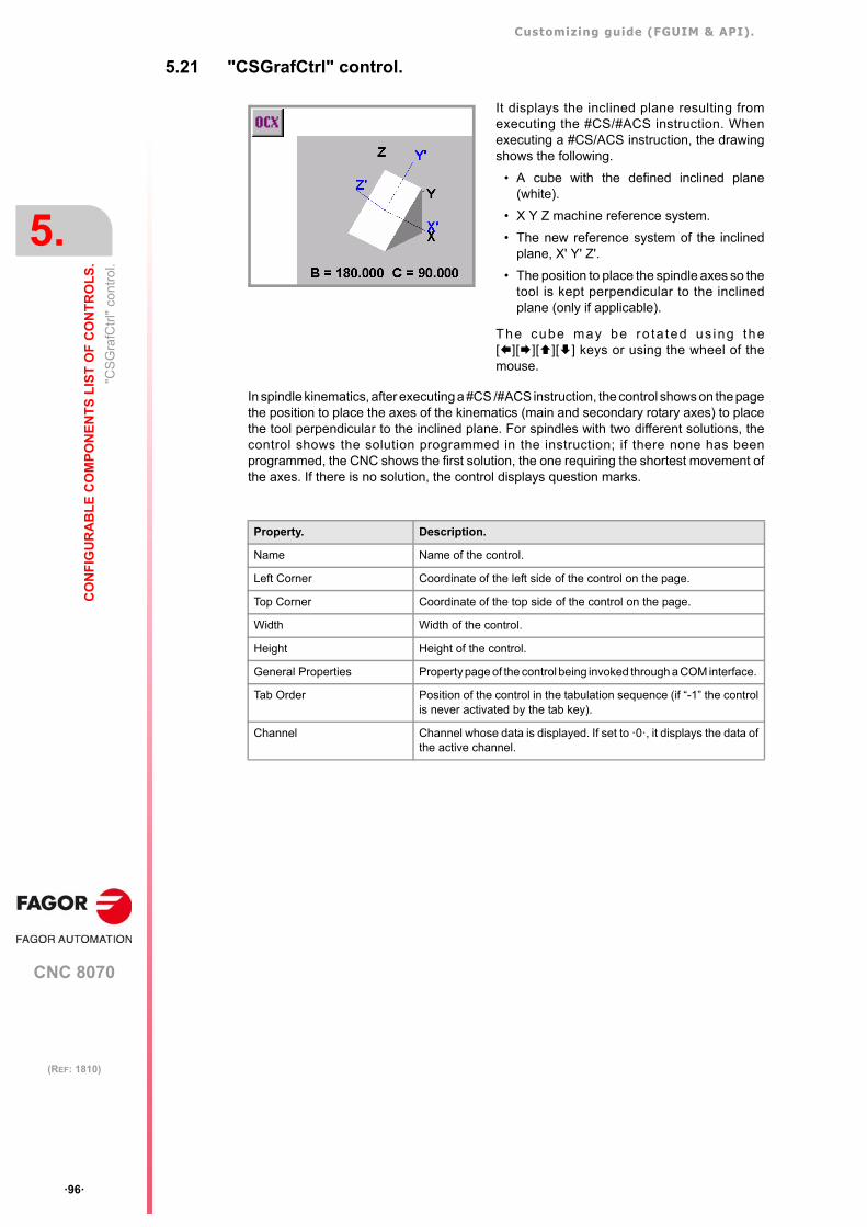
Customizing guide (FGUIM & API).
CNC 8070
5.
CO
NF
IGU
RA
BL
E C
OM
PO
NE
NT
S L
IST
OF
CO
NT
RO
LS
.
"CS
Gra
fCtr
l" c
ontr
ol.
·96·
(REF: 1810)
5.21 "CSGrafCtrl" control.
In spindle kinematics, after executing a #CS /#ACS instruction, the control shows on the pagethe position to place the axes of the kinematics (main and secondary rotary axes) to placethe tool perpendicular to the inclined plane. For spindles with two different solutions, thecontrol shows the solution programmed in the instruction; if there none has beenprogrammed, the CNC shows the first solution, the one requiring the shortest movement ofthe axes. If there is no solution, the control displays question marks.
It displays the inclined plane resulting fromexecuting the #CS/#ACS instruction. Whenexecuting a #CS/ACS instruction, the drawingshows the following.
• A cube with the defined inclined plane(white).
• X Y Z machine reference system.
• The new reference system of the inclinedplane, X' Y' Z'.
• The position to place the spindle axes so thetool is kept perpendicular to the inclinedplane (only if applicable).
The cube may be ro ta ted us ing the[][][][] keys or using the wheel of themouse.
Property. Description.
Name Name of the control.
Left Corner Coordinate of the left side of the control on the page.
Top Corner Coordinate of the top side of the control on the page.
Width Width of the control.
Height Height of the control.
General Properties Property page of the control being invoked through a COM interface.
Tab Order Position of the control in the tabulation sequence (if “-1” the controlis never activated by the tab key).
Channel Channel whose data is displayed. If set to ·0·, it displays the data ofthe active channel.
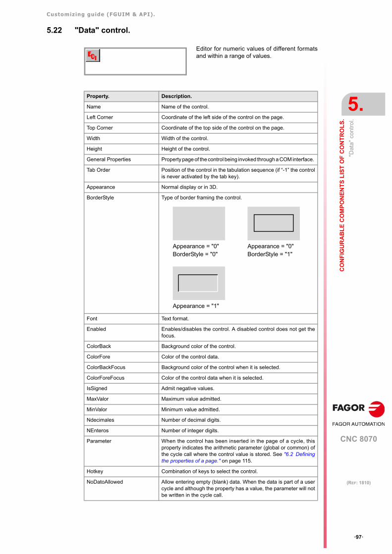
Customizing guide (FGUIM & API).
CNC 8070
CO
NF
IGU
RA
BL
E C
OM
PO
NE
NT
S L
IST
OF
CO
NT
RO
LS
.
5.
"Dat
a" c
ontr
ol.
·97·
(REF: 1810)
5.22 "Data" control.
Editor for numeric values of different formatsand within a range of values.
Property. Description.
Name Name of the control.
Left Corner Coordinate of the left side of the control on the page.
Top Corner Coordinate of the top side of the control on the page.
Width Width of the control.
Height Height of the control.
General Properties Property page of the control being invoked through a COM interface.
Tab Order Position of the control in the tabulation sequence (if “-1” the controlis never activated by the tab key).
Appearance Normal display or in 3D.
BorderStyle Type of border framing the control.
Font Text format.
Enabled Enables/disables the control. A disabled control does not get thefocus.
ColorBack Background color of the control.
ColorFore Color of the control data.
ColorBackFocus Background color of the control when it is selected.
ColorForeFocus Color of the control data when it is selected.
IsSigned Admit negative values.
MaxValor Maximum value admitted.
MinValor Minimum value admitted.
Ndecimales Number of decimal digits.
NEnteros Number of integer digits.
Parameter When the control has been inserted in the page of a cycle, thisproperty indicates the arithmetic parameter (global or common) ofthe cycle call where the control value is stored. See "6.2 Definingthe properties of a page." on page 115.
Hotkey Combination of keys to select the control.
NoDatoAllowed Allow entering empty (blank) data. When the data is part of a usercycle and although the property has a value, the parameter will notbe written in the cycle call.
Appearance = "0"BorderStyle = "0"
Appearance = "0"BorderStyle = "1"
Appearance = "1"
Customizing guide (FGUIM & API).
CNC 8070
5.
CO
NF
IGU
RA
BL
E C
OM
PO
NE
NT
S L
IST
OF
CO
NT
RO
LS
.
"Dat
a" c
ontr
ol.
·98·
(REF: 1810)
PsAllowed Allow the value to be a local, global or common arithmetic parameter.When executing the user cycle, the control will get the value of thisparameter. At the time of execution, the user cycle where the controlis located will have to replace the parameter with its value.
SsAllowed Allow the value to be a spindle name. The user cycle where thecontrol is located must manage what to do with that data.
Justify Text alignment.• If "0", no.• If “1”, left align.• If "2", centered.• If “3”, right align.
IsValid It indicates whether the value is valid or not.
FocusChangeKeys Keys used to change the focus to the next control, same as[CTRL]+[F2]. This property is valid when the control is inserted in aFagor component. On the pages of user components, the arrow keysand the tab of the keyboard always lets you change the focus to theprevious or next control according to a set tab order.
Property. Description.
Customizing guide (FGUIM & API).
CNC 8070
CO
NF
IGU
RA
BL
E C
OM
PO
NE
NT
S L
IST
OF
CO
NT
RO
LS
.
5.
"Dat
a" c
ontr
ol.
·99·
(REF: 1810)
5.22.1 Methods of the "Dato" control to be used in scripts.
BSTR GetValue ()
Returs the edited data.
void SetValue(BSTR lNewValue)
It writes a value in the control.
boolean HandledEscape()
If [ESC] is pressed after having edited something without confirming it with an [ENTER], thismethod restores the previous value. If it restores it, it returns TRUE.
void SendKeys(boolean bSend)
It indicates to the control to send [TAB] when pressing [ENTER] on it.
msgbox "Edited value:" + MiControlDato.GetValue
MiControlDato.SetValue "-125.2"
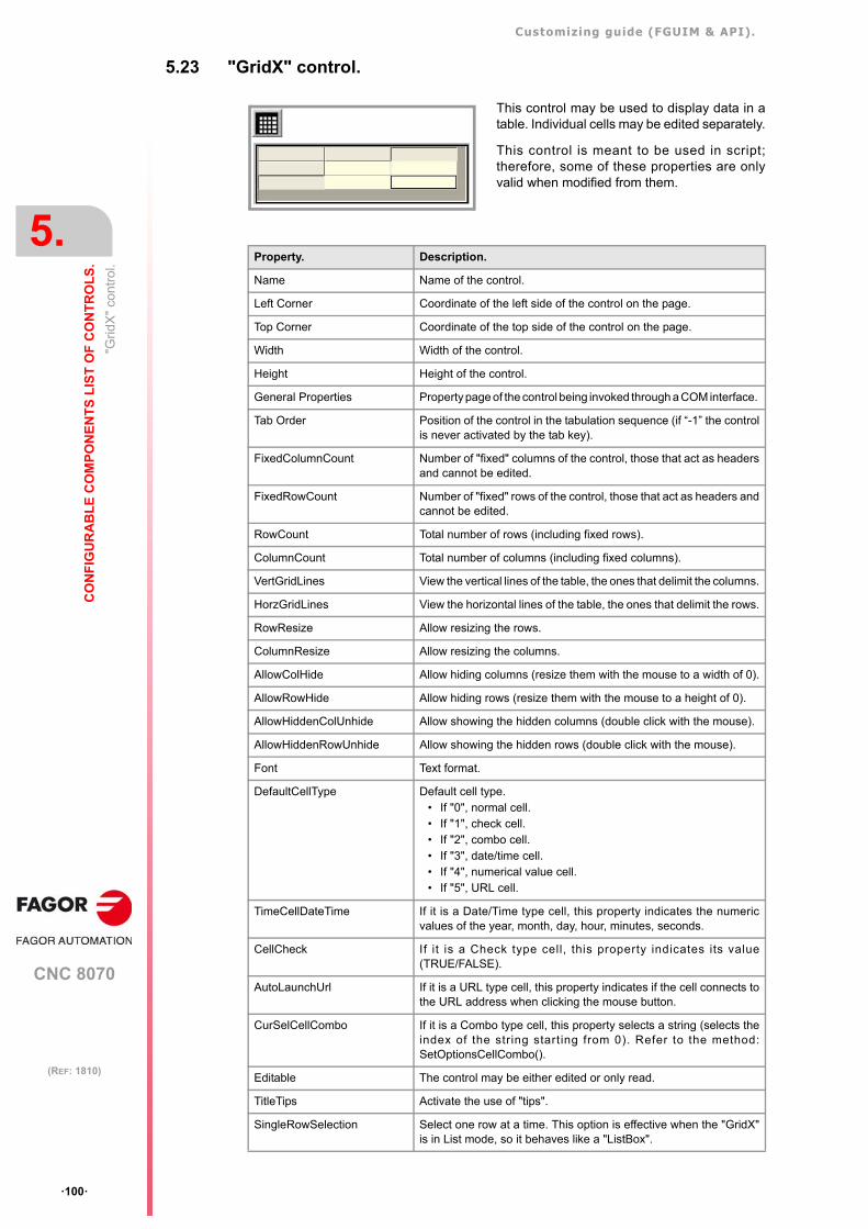
Customizing guide (FGUIM & API).
CNC 8070
5.
CO
NF
IGU
RA
BL
E C
OM
PO
NE
NT
S L
IST
OF
CO
NT
RO
LS
.
"Gri
dX"
cont
rol.
·100·
(REF: 1810)
5.23 "GridX" control.
This control may be used to display data in atable. Individual cells may be edited separately.
This control is meant to be used in script;therefore, some of these properties are onlyvalid when modified from them.
Property. Description.
Name Name of the control.
Left Corner Coordinate of the left side of the control on the page.
Top Corner Coordinate of the top side of the control on the page.
Width Width of the control.
Height Height of the control.
General Properties Property page of the control being invoked through a COM interface.
Tab Order Position of the control in the tabulation sequence (if “-1” the controlis never activated by the tab key).
FixedColumnCount Number of "fixed" columns of the control, those that act as headersand cannot be edited.
FixedRowCount Number of "fixed" rows of the control, those that act as headers andcannot be edited.
RowCount Total number of rows (including fixed rows).
ColumnCount Total number of columns (including fixed columns).
VertGridLines View the vertical lines of the table, the ones that delimit the columns.
HorzGridLines View the horizontal lines of the table, the ones that delimit the rows.
RowResize Allow resizing the rows.
ColumnResize Allow resizing the columns.
AllowColHide Allow hiding columns (resize them with the mouse to a width of 0).
AllowRowHide Allow hiding rows (resize them with the mouse to a height of 0).
AllowHiddenColUnhide Allow showing the hidden columns (double click with the mouse).
AllowHiddenRowUnhide Allow showing the hidden rows (double click with the mouse).
Font Text format.
DefaultCellType Default cell type.• If "0", normal cell.• If "1", check cell.• If "2", combo cell.• If "3", date/time cell.• If "4", numerical value cell.• If "5", URL cell.
TimeCellDateTime If it is a Date/Time type cell, this property indicates the numericvalues of the year, month, day, hour, minutes, seconds.
CellCheck If it is a Check type cell, this property indicates its value(TRUE/FALSE).
AutoLaunchUrl If it is a URL type cell, this property indicates if the cell connects tothe URL address when clicking the mouse button.
CurSelCellCombo If it is a Combo type cell, this property selects a string (selects theindex of the string starting from 0). Refer to the method:SetOptionsCellCombo().
Editable The control may be either edited or only read.
TitleTips Activate the use of "tips".
SingleRowSelection Select one row at a time. This option is effective when the "GridX"is in List mode, so it behaves like a "ListBox".
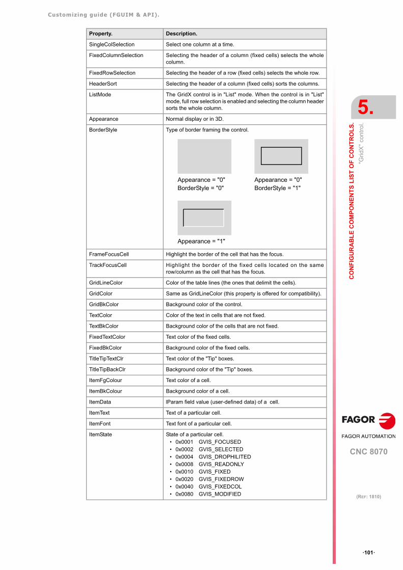
Customizing guide (FGUIM & API).
CNC 8070
CO
NF
IGU
RA
BL
E C
OM
PO
NE
NT
S L
IST
OF
CO
NT
RO
LS
.
5.
"Gri
dX"
cont
rol.
·101·
(REF: 1810)
SingleColSelection Select one column at a time.
FixedColumnSelection Selecting the header of a column (fixed cells) selects the wholecolumn.
FixedRowSelection Selecting the header of a row (fixed cells) selects the whole row.
HeaderSort Selecting the header of a column (fixed cells) sorts the columns.
ListMode The GridX control is in "List" mode. When the control is in "List"mode, full row selection is enabled and selecting the column headersorts the whole column.
Appearance Normal display or in 3D.
BorderStyle Type of border framing the control.
FrameFocusCell Highlight the border of the cell that has the focus.
TrackFocusCell Highlight the border of the fixed cells located on the samerow/column as the cell that has the focus.
GridLineColor Color of the table lines (the ones that delimit the cells).
GridColor Same as GridLineColor (this property is offered for compatibility).
GridBkColor Background color of the control.
TextColor Color of the text in cells that are not fixed.
TextBkColor Background color of the cells that are not fixed.
FixedTextColor Text color of the fixed cells.
FixedBkColor Background color of the fixed cells.
TitleTipTextClr Text color of the "Tip" boxes.
TitleTipBackClr Background color of the "Tip" boxes.
ItemFgColour Text color of a cell.
ItemBkColour Background color of a cell.
ItemData lParam field value (user-defined data) of a cell.
ItemText Text of a particular cell.
ItemFont Text font of a particular cell.
ItemState State of a particular cell.• 0x0001 GVIS_FOCUSED• 0x0002 GVIS_SELECTED• 0x0004 GVIS_DROPHILITED• 0x0008 GVIS_READONLY• 0x0010 GVIS_FIXED• 0x0020 GVIS_FIXEDROW• 0x0040 GVIS_FIXEDCOL• 0x0080 GVIS_MODIFIED
Property. Description.
Appearance = "0"BorderStyle = "0"
Appearance = "0"BorderStyle = "1"
Appearance = "1"
Customizing guide (FGUIM & API).
CNC 8070
5.
CO
NF
IGU
RA
BL
E C
OM
PO
NE
NT
S L
IST
OF
CO
NT
RO
LS
.
"Gri
dX"
cont
rol.
·102·
(REF: 1810)
ItemFormat Format of a cell. • 0x00000000 DT_TOP• 0x00000000 DT_LEFT• 0x00000001 DT_CENTER• 0x00000002 DT_RIGHT• 0x00000004 DT_VCENTER• 0x00000008 DT_BOTTOM• 0x00000010 DT_WORDBREAK• 0x00000020 DT_SINGLELINE • 0x00000040 DT_EXPANDTABS• 0x00000080 DT_TABSTOP• 0x00000100 DT_NOCLIP • 0x00000200 DT_EXTERNALLEADING• 0x00000400 DT_CALCRECT• 0x00000800 DT_NOPREFIX• 0x00001000 DT_INTERNAL
ImageList Select an "ImageList" object.
ItemImage Index of the image for a cell.
StyleCellCombo Sta te o f a Combo type ce l l . Re fe r to the method :SetOptionsCellCombo().
• 0x0001L CBS_SIMPLE • 0x0002L CBS_DROPDOWN• 0x0003L CBS_DROPDOWNLIST• 0x0010L CBS_OWNERDRAWFIXED• 0x0020L CBS_OWNERDRAWVARIABLE• 0x0040L CBS_AUTOHSCROLL• 0x0080L CBS_OEMCONVERT• 0x0100L CBS_SORT• 0x0200L CBS_HASSTRINGS• 0x0400L CBS_NOINTEGRALHEIGHT• 0x0800L CBS_DISABLENOSCROLL• 0x2000L CBS_UPPERCASE• 0x4000L CBS_LOWERCASE
StyleCellDateTime Style of a DateTime type cell. • 0x0001 DTS_UPDOWN; Use UPDOWN instead of
MONTHCAL.• 0x0002 DTS_SHOWNONE; To select nothing.• 0x0000 DTS_SHORTDATEFORMAT• 0x0004 DTS_LONGDATEFORMAT• 0x0008 DTS_TIMEFORMAT• 0x0010 DTS_APPCANPARSE; Allows user strings.• 0x0020 DTS_RIGHTALIGN
EnableSelection To select the cell.
RejectEditAttempts Reject the attempts to edit a cell.
RejectEditChanges Reject the attempts to modify a cell.
Property. Description.
Customizing guide (FGUIM & API).
CNC 8070
CO
NF
IGU
RA
BL
E C
OM
PO
NE
NT
S L
IST
OF
CO
NT
RO
LS
.
5.
"Gri
dX"
cont
rol.
·103·
(REF: 1810)
5.23.1 Methods of the "GridX" control to be used in scripts.
CellNormal (nRow, nCol)
Set the given cell as Normal type cell.
CellReadonly (nRow, nCol)
Set the given cell as read-only.
SetItalics (nItalics)
Set the grid font in Italic
ExpandToFit (bExpToFit)
Expand the rows and columns to fit the grid area. If bExpToFit = TRUE the fixed rows andcolumns are also expanded.
ExpandColumnsToFit (bExpToFit)
Expand the columns to fit the whole width of the control. If bExpToFit = TRUE, the fixedcolumns will also be expanded.
ExpandRowsToFit (bExpToFit)
Expand the rows to fit the whole height of the control. If bExpToFit = TRUE the fixed rowswill also be expanded.
ExpandLastColumn()
Expand the last column to fit the whole width of the control.
AutoSizeRows()
Resize all rows to fit the contents.
AutoSizeRow (Row)
Resize the given row to fit its largest item.
AutoSizeColumns (nAutoSizeStyle)
Auto sizes all columns. nAutoSizeStyle indicates how to do it.
AutoSizeColumn (nCol, nAutoSizeStyle)
Auto sizes the column to the size of the largest item. nAutoSizeStyle indicates how to do it,like the previous function.
AutoSize (nAutoSizeStyle)
Auto sizes all rows and columns to the largest item. nAutoSizeStyle indicates how to do it,like the previous function.
VerticalHeader (nNewValue)
If nNewValue = TRUE, put the texts of the "fixed" cells vertically.
GetRowHeight (nRow)
Get the height of the indicated row.
SetRowHeight (nRow, nHeight)
Set the height of the indicated row.
0 GVS_DEFAULT
1 GVS_HEADER; Resize using the data of the "fixed" columns.
2 GVS_DATA; Resize using the data of the "non-fixed" columns.
3 GVS_BOTH; Resize using the data of the "fixed" and "non-fixed" columns.
Customizing guide (FGUIM & API).
CNC 8070
5.
CO
NF
IGU
RA
BL
E C
OM
PO
NE
NT
S L
IST
OF
CO
NT
RO
LS
.
"Gri
dX"
cont
rol.
·104·
(REF: 1810)
GetColumnWidth (nCol)
Get the width of the indicated column.
SetColumnWidth (nCol, nWidth)
Set the width of the indicated column.
GetSelectedCount()
Number of selected cells.
SetFocusCell (nRow, nCol)
Set the focus in the indicated cell.
GetFocusCell (pnRow, pnCol)
Number of row and column of the cell that has the focus.
SetModified (bModified, nRow, nCol)
Set the GVIS_MODIFIED flag to the cell. If nRow=-1 and nCol=-1, the only thing it does isto set the internal flag to the bModified value.
GetModified (nRow, nCol)
Check if the cell has the GVIS_MODIFIED flag activated. If nRow = -1 and nCol = -1, returnsthe internal value of the modification flag.
IsCellFixed (nRow, nCol)
Return if the cell is a fixed cell.
IsItemEditing (nRow, nCol)
Return if the cell is currently being edited.
InsertColumn (strHeading, nFormat, nColumn)
Insert a column at the position given by nColumn. If nColumn is -1, insert a column at theend. strHeading is the header of the column. The format of the cells is the one indicated bythe temFormat proper ty ; i f equa l to -1 , the format is the one by defau l tDT_CENTER|DT_VCENTER|DT_SINGLELINE.
InsertRow (strHeading, nRow)
Insert a row at the position given by nRow. If nRow is -1, insert a row at the end. strHeadingis the header of the row. The format of each cell in the row will be that of the cell in the firstrow of the same column.
DeleteColumn (nColumn)
Delete the indicated column.
DeleteRow (long nRow)
Delete the indicated row.
DeleteNonFixedRows()
Delete all "non-fixed" rows.
DeleteAllItems()
Delete the whole contents of the grid.
ClearCells (nRowMin, nColMin, nRowMax, nColMax)
Clear a range of cells.
EnsureVisible (nRow, nCol)
Ensure that the specified cell is visible
Customizing guide (FGUIM & API).
CNC 8070
CO
NF
IGU
RA
BL
E C
OM
PO
NE
NT
S L
IST
OF
CO
NT
RO
LS
.
5.
"Gri
dX"
cont
rol.
·105·
(REF: 1810)
IsCellVisible (nRow, nCol)
Return if the cell is visible
IsCellEditable (nRow, nCol)
Return if the cell may be edited.
IsCellSelected (nRow, nCol)
Return if the cell is selected
IsValid (nRow, nCol)
Indicate if nRow and nCol are valid.
Save (filename, chSeparator)
Save the grid data into the "filename" file. chSeparator is the character that separates thefields"; if not defined, the "," character is used.
Load (filename, chSeparator)
Load the "filename" file into the grid. chSeparator is the character that separates the fields";if not defined, the "," character is used.
ResetSelectedRange()
Reset the selected range.
SetSelectedRange (nMinRow, nMinCol, nMaxRow, nMaxCol, bSelectCells)
Select the cells of a range. Si bSelectCells = FALSE, se deseleccionan las celdas.
GetSelectedCellRange (pnRowMin, pnColMin, pnRowMax, pnColMax)
Get the range of selected cells.
Copy()
Copy the contents of the cell to the clipboard (same as [CTRL]+[C]).
Cut()
Copy the contents of the cell to the clipboard and delete it (same as [CTRL]+[X]).
Paste()
Copy the contents of the clipboard into the cell (same as [CTRL]+[V]).
CutSelectedText
Delete the contents from the selected cells.
SelectAll
Select all cells in the grid (same as [CTRL]+[A]).
SortItems (nCol, bAscending)
Sort the items of the given column. The comparison is made by text and may be sorted upor down.
Print()
Print the grid control on the user selected device.
SetCellType (nRow, nCol, nCellType)
Set the type of cell. The types are the same as those of the property DefaultCellType.
SetOptionsCellCombo (nRow, nCol, sArrayStrings)
If it is a Combo type cell, the array of strings sArrayStrings defines its options.
Customizing guide (FGUIM & API).
CNC 8070
5.
CO
NF
IGU
RA
BL
E C
OM
PO
NE
NT
S L
IST
OF
CO
NT
RO
LS
.
"Gri
dX"
cont
rol.
·106·
(REF: 1810)
AddStringCellCombo (nRow, nCol, str)
If it is a Combo type cell, add a string to it.
DeleteStringCellCombo (nRow, nCol, nIndex)
If it is a Combo type cell, delete the nIndex string.
InsertStringCellCombo (long nRow, long nCol, long nIndex, LPCTSTR str)
If it is a Combo type cell, insert a string in the nIndex.
ResetContentCellCombo (long nRow, long nCol)
If it is a Combo type cell, it resets its state.
SelectStringComboBox (nRow, nCol, str)
If it is a Combo type cell, it looks in all its strings a string starting with "str" and selects it.
SetCurrentTimeCellDateTime (nRow, nCol)
If it is a DateTime type cell, write the current date.
RedrawCell (nRow, nCol)
Redraw (refresh) the indicated cell.
RedrawRow (nRow)
Redraw (refresh) the indicated row.
RedrawColumn (nCol)
Redraw (refresh) the indicated column.
GetFormat()
Get the default format. The format is the same as that of the ItemFormat property.
SetFormat (nFormat)
Set the default format. The format is the same as that of the ItemFormat property.
Refresh()
Redraw (refresh) the entire grid.
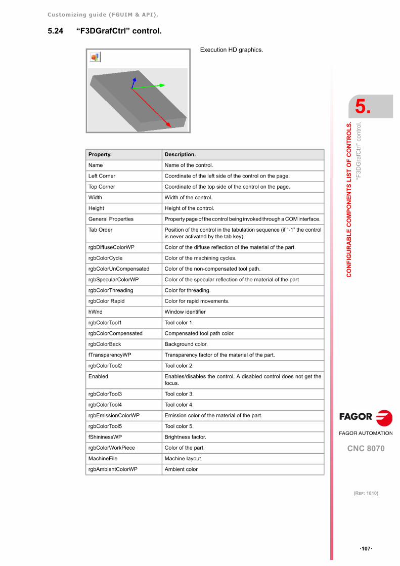
Customizing guide (FGUIM & API).
CNC 8070
CO
NF
IGU
RA
BL
E C
OM
PO
NE
NT
S L
IST
OF
CO
NT
RO
LS
.
5.
“F3D
Gra
fCtr
l” co
ntro
l.
·107·
(REF: 1810)
5.24 “F3DGrafCtrl” control.
Execution HD graphics.
Property. Description.
Name Name of the control.
Left Corner Coordinate of the left side of the control on the page.
Top Corner Coordinate of the top side of the control on the page.
Width Width of the control.
Height Height of the control.
General Properties Property page of the control being invoked through a COM interface.
Tab Order Position of the control in the tabulation sequence (if “-1” the controlis never activated by the tab key).
rgbDiffuseColorWP Color of the diffuse reflection of the material of the part.
rgbColorCycle Color of the machining cycles.
rgbColorUnCompensated Color of the non-compensated tool path.
rgbSpecularColorWP Color of the specular reflection of the material of the part
rgbColorThreading Color for threading.
rgbColor Rapid Color for rapid movements.
hWnd Window identifier
rgbColorTool1 Tool color 1.
rgbColorCompensated Compensated tool path color.
rgbColorBack Background color.
fTransparencyWP Transparency factor of the material of the part.
rgbColorTool2 Tool color 2.
Enabled Enables/disables the control. A disabled control does not get thefocus.
rgbColorTool3 Tool color 3.
rgbColorTool4 Tool color 4.
rgbEmissionColorWP Emission color of the material of the part.
rgbColorTool5 Tool color 5.
fShininessWP Brightness factor.
rgbColorWorkPiece Color of the part.
MachineFile Machine layout.
rgbAmbientColorWP Ambient color
Customizing guide (FGUIM & API).
CNC 8070
5.
CO
NF
IGU
RA
BL
E C
OM
PO
NE
NT
S L
IST
OF
CO
NT
RO
LS
.
“F3D
Gra
fCtr
l” co
ntro
l.
·108·
(REF: 1810)
5.24.1 Methods of the "F3DGrafCtrl" control to be used in scripts.
void AboutBox
Show the AboutBox box.
OLE_HANDLE GetMenu
Retrieve the identifier from the indicated menu.
Boolean HelpWanted
Display control help.
Boolean IsUserCustomized
The user can modify the control properties.
void LoadMachine (lpszFileName (string))
Load a machine layout (xca file).
void LoadPiece (lpsz FileName(string))
Load a part.
void PrintToFile (lpszFileName(string))
Print an image to a file.
Boolean ReloadComponent
Load the component.
void ResetPressed (Channel(Integer), simulation(long)
Indicates that a reset has been pressed for a channel, and whether it is execution orsimulation.
void SerializeComponentProperties (pLongPropExchange(long))
Preservation of the properties of the component.
void SerializePageProperties (pLongPropExchange(long))
Preservation of the properties of the page.
void SetRGBComponentsDefaultValues
Update the control with the default RGB values.

Customizing guide (FGUIM & API).
CNC 8070
CO
NF
IGU
RA
BL
E C
OM
PO
NE
NT
S L
IST
OF
CO
NT
RO
LS
.
5.
“F3D
Gra
fCtr
l SIM
U”
cont
rol.
·109·
(REF: 1810)
5.25 “F3DGrafCtrl SIMU” control.
Simulation HD graphics.
Property. Description.
Name Name of the control.
Left Corner Coordinate of the left side of the control on the page.
Top Corner Coordinate of the top side of the control on the page.
Width Width of the control.
Height Height of the control.
General Properties Property page of the control being invoked through a COM interface.
Tab Order Position of the control in the tabulation sequence (if “-1” the controlis never activated by the tab key).
rgbDiffuseColorWP Color of the diffuse reflection of the material of the part.
rgbColorCycle Color of the machining cycles.
rgbColorUnCompensated Color of the non-compensated tool path.
rgbSpecularColorWP Color of the specular reflection of the material of the part
rgbColorThreading Color for threading.
rgbColor Rapid Color for rapid movements.
hWnd Window identifier
rgbColorTool1 Tool color 1.
rgbColorCompensated Compensated tool path color.
rgbColorBack Background color.
fTransparencyWP Transparency factor of the material of the part.
rgbColorTool2 Tool color 2.
Enabled Enables/disables the control. A disabled control does not get thefocus.
rgbColorTool3 Tool color 3.
rgbColorTool4 Tool color 4.
rgbEmissionColorWP Emission color of the material of the part.
rgbColorTool5 Tool color 5.
fShininessWP Brightness factor.
rgbColorWorkPiece Color of the part.
MachineFile Machine layout.
rgbAmbientColorWP Ambient color

Customizing guide (FGUIM & API).
CNC 8070
5.
CO
NF
IGU
RA
BL
E C
OM
PO
NE
NT
S L
IST
OF
CO
NT
RO
LS
.
“F3D
Gra
fCtr
l SIM
U”
cont
rol.
·110·
(REF: 1810)
5.25.1 Methods of the "F3DGrafCtrl SIMU" control to be used in scripts.
void AboutBox
Show the AboutBox box.
OLE_HANDLE GetMenu
Retrieve the identifier from the indicated menu.
Boolean HelpWanted
Display control help.
Boolean IsUserCustomized
The user can modify the control properties.
void LoadMachine (lpszFileName (string))
Load a machine layout (xca file).
void LoadPiece (lpsz FileName(string))
Load a part.
void PrintToFile (lpszFileName(string))
Print an image to a file.
Boolean ReloadComponent
Load the component.
void ResetPressed (Channel(Integer), simulation(long)
Indicates that a reset has been pressed for a channel, and whether it is execution orsimulation.
void SerializeComponentProperties (pLongPropExchange(long))
Preservation of the properties of the component.
void SerializePageProperties (pLongPropExchange(long))
Preservation of the properties of the page.
void SetRGBComponentsDefaultValues
Update the control with the default RGB values.
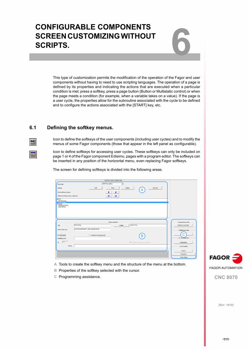
CNC 8070
6
·111·
(REF: 1810)
6. CONFIGURABLE COMPONENTS SCREEN CUSTOMIZING WITHOUT SCRIPTS.
This type of customization permits the modification of the operation of the Fagor and usercomponents without having to need to use scripting languages. The operation of a page isdefined by its properties and indicating the actions that are executed when a particularcondition is met; press a softkey, press a page button (Button or Multistatic control) or whenthe page meets a condition (for example, when a variable takes on a value). If the page isa user cycle, the properties allow for the subroutine associated with the cycle to be definedand to configure the actions associated with the [START] key, etc.
6.1 Defining the softkey menus.
The screen for defining softkeys is divided into the following areas.
A Tools to create the softkey menu and the structure of the menu at the bottom.
B Properties of the softkey selected with the cursor.
C Programming assistance.
Icon to define the softkeys of the user components (including user cycles) and to modify themenus of some Fagor components (those that appear in the left panel as configurable).
Icon to define softkeys for accessing user cycles. These softkeys can only be included onpage 1 or 4 of the Fagor component Edisimu, pages with a program editor. The softkeys canbe inserted in any position of the horizontal menu, even replacing Fagor softkeys.
A
B C
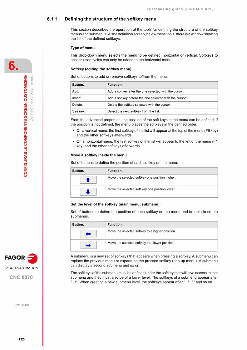
Customizing guide (FGUIM & API).
CNC 8070
6.
CO
NF
IGU
RA
BL
E C
OM
PO
NE
NT
S S
CR
EE
N C
US
TO
MIZ
ING
Def
inin
g th
e so
ftkey
me
nus.
·112·
(REF: 1810)
6.1.1 Defining the structure of the softkey menu.
This section describes the operation of the tools for defining the structure of the softkeymenus and submenus. At the definition screen, below these tools, there is a window showingthe list of the defined softkeys.
Type of menu.
This drop-down menu selects the menu to be defined; horizontal or vertical. Softkeys toaccess user cycles can only be added to the horizontal menu.
Softkey (editing the softkey menu).
Set of buttons to add or remove softkeys to/from the menu.
From the advanced properties, the position of the soft keys in the menu can be defined; Ifthe position is not defined, the menu places the softkeys in the defined order.
• On a vertical menu, the first softkey of the list will appear at the top of the menu (F9 key)and the other softkeys afterwards.
• On a horizontal menu, the first softkey of the list will appear to the left of the menu (F1key) and the other softkeys afterwards.
Move a softkey inside the menu.
Set of buttons to define the position of each softkey on the menu.
Set the level of the softkey (main menu, submenu).
Set of buttons to define the position of each softkey on the menu and be able to createsubmenus.
A submenu is a new set of softkeys that appears when pressing a softkey. A submenu canreplace the previous menu or expand on the pressed softkey (pop-up menu). A submenucan display a second submenu and so on.
The softkeys of the submenu must be defined under the softkey that will give access to thatsubmenu and they must also be of a lower level. The softkeys of a submenu appear after"...\". When creating a new submenu level, the softkeys appear after "...\...\" and so on.
Button. Function.
Add. Add a softkey after the one selected with the cursor.
Insert. Add a softkey before the one selected with the cursor.
Delete. Delete the softkey selected with the cursor.
See next. Select the next softkey from the list.
Button. Function.
Move the selected softkey one position higher.
Move the selected soft key one position lower.
Button. Function.
Move the selected softkey to a higher position.
Move the selected softkey to a lower position.
Customizing guide (FGUIM & API).
CNC 8070
CO
NF
IGU
RA
BL
E C
OM
PO
NE
NT
S S
CR
EE
N C
US
TO
MIZ
ING
6.
Def
inin
g th
e so
ftkey
me
nus.
·113·
(REF: 1810)
6.1.2 Defining the properties of a softkey.
Basic properties of the softkeys.
Title.
Text of the softkey. The text of a softkey must not start with the characters "...\".
To have text in different languages, write the identifier associated with a text defined at thetext editor of the Fguim. See "5.1.2 Texts in different languages in the controls." on page 57.
Image.
File and path of the image to be shown on the softkey. The softkeys with a image assignedto it will not show the title of the softkey. The drawings must be in bmp format. The size ofthe images must be 48 x 48 pixels for vertical softkeys and 96 (width) and 32 (height) pixelsfor the horizontal ones.
Action when pressing the softkey.
Action to be executed by the softkey when it is pressed. Each softkey may be assigned twoactions, both separated by the & character. These commands may be accessed with the"Interface commands" button. See "6.3 Interface operation commands." on page 120.
Advanced properties.
These properties only appear when the "Advanced" checkbox is activated.
Condition for disabling the softkey.
Condition that disables the softkey. For example, the softkey may be disabled dependingon the value of a variable. The condition may be defined using variables or expressions. See"5.1.1 Variables and expressions in the controls." on page 54.
Softkey ID.
Softkey identifier. Fguim assigns a unique non-editable identifier to each softkey. Thisidentifier is required for using the softkey from the scripts.
Bi-state.
The softkey stays pressed.
Action when releasing the softkey.
Action to be executed by the softkey when it is released. Its operation is the same as the"Action when pressing the softkey” property. This property is only available for bi-statesoftkeys.
Condition for pressing.
Condition for keeping the softkey pressed. The condition may be defined using variables orexpressions. See "5.1.1 Variables and expressions in the controls." on page 54. Thisproperty is only available for bi-state softkeys.
POS (softkey position).
Position of the softkey on the menu. If the position is not defined or it is defined with as ·0·,the softkey position on the menu will be given by its position on the list of softkeys. On verticalmenus, position ·1· corresponds to the highest softkey (F12 key) and on the horizontalmenus, position ·1· corresponds to the leftmost softkey (F1 key).
On the main menu, this property may be used to place the softkeys in any position of themenu, without having to define empty intermediate softkeys. The order of the softkeys onthe submenu is defined only by their order on the list, their position cannot be defined.
When defining a position, if there is a Fagor softkey in that position, the Fagor softkey maybe replaced by the new one using the property "Replace Fagor softkey".
Customizing guide (FGUIM & API).
CNC 8070
6.
CO
NF
IGU
RA
BL
E C
OM
PO
NE
NT
S S
CR
EE
N C
US
TO
MIZ
ING
Def
inin
g th
e so
ftkey
me
nus.
·114·
(REF: 1810)
Replace Fagor softkey
The defined softkey replaces the Fagor softkey. A Fagor softkey cannot be replaced if theposition has not been defined or has been defined as ·0·.
PopUp
This property determines whether the submenu replaces the previous menu or it is a dropsubmenu expandable (PopUp). On a vertical menu, the softkeys that access a submenualways have this property actie.
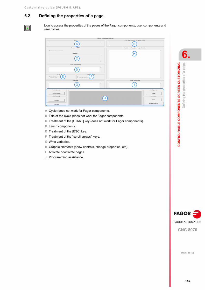
Customizing guide (FGUIM & API).
CNC 8070
CO
NF
IGU
RA
BL
E C
OM
PO
NE
NT
S S
CR
EE
N C
US
TO
MIZ
ING
6.
Def
inin
g th
e pr
oper
ties
of a
pa
ge.
·115·
(REF: 1810)
6.2 Defining the properties of a page.
A Cycle (does not work for Fagor components.
B Title of the cycle (does not work for Fagor components.
C Treatment of the [START] key (does not work for Fagor components).
D Lauch components.
E Treatment of the [ESC] key.
F Treatment of the "scroll arrows" keys.
G Write variables.
H Graphic elements (show controls, change properties, etc).
I Activate deactivate pages.
J Programming assistance.
Icon to access the properties of the pages of the Fagor components, user components anduser cycles.
A B
H
IG
C
D
E F
J
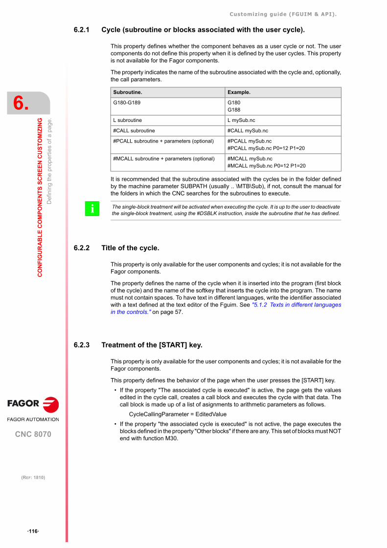
Customizing guide (FGUIM & API).
CNC 8070
6.
CO
NF
IGU
RA
BL
E C
OM
PO
NE
NT
S S
CR
EE
N C
US
TO
MIZ
ING
Def
inin
g th
e pr
oper
ties
of a
pa
ge.
·116·
(REF: 1810)
6.2.1 Cycle (subroutine or blocks associated with the user cycle).
This property defines whether the component behaves as a user cycle or not. The usercomponents do not define this property when it is defined by the user cycles. This propertyis not available for the Fagor components.
The property indicates the name of the subroutine associated with the cycle and, optionally,the call parameters.
It is recommended that the subroutine associated with the cycles be in the folder definedby the machine parameter SUBPATH (usually .. \MTB\Sub), if not, consult the manual forthe folders in which the CNC searches for the subroutines to execute.
6.2.2 Title of the cycle.
This property is only available for the user components and cycles; it is not available for theFagor components.
The property defines the name of the cycle when it is inserted into the program (first blockof the cycle) and the name of the softkey that inserts the cycle into the program. The namemust not contain spaces. To have text in different languages, write the identifier associatedwith a text defined at the text editor of the Fguim. See "5.1.2 Texts in different languagesin the controls." on page 57.
6.2.3 Treatment of the [START] key.
This property is only available for the user components and cycles; it is not available for theFagor components.
This property defines the behavior of the page when the user presses the [START] key.
• If the property "The associated cycle is executed" is active, the page gets the valuesedited in the cycle call, creates a call block and executes the cycle with that data. Thecall block is made up of a list of asignments to arithmetic parameters as follows.
CycleCallingParameter = EditedValue
• If the property "the associated cycle is executed" is not active, the page executes theblocks defined in the property "Other blocks" if there are any. This set of blocks must NOTend with function M30.
Subroutine. Example.
G180-G189 G180G188
L subroutine L mySub.nc
#CALL subroutine #CALL mySub.nc
#PCALL subroutine + parameters (optional) #PCALL mySub.nc#PCALL mySub.nc P0=12 P1=20
#MCALL subroutine + parameters (optional) #MCALL mySub.nc#MCALL mySub.nc P0=12 P1=20
The single-block treatment will be activated when executing the cycle. It is up to the user to deactivatethe single-block treatment, using the #DSBLK instruction, inside the subroutine that he has defined.i
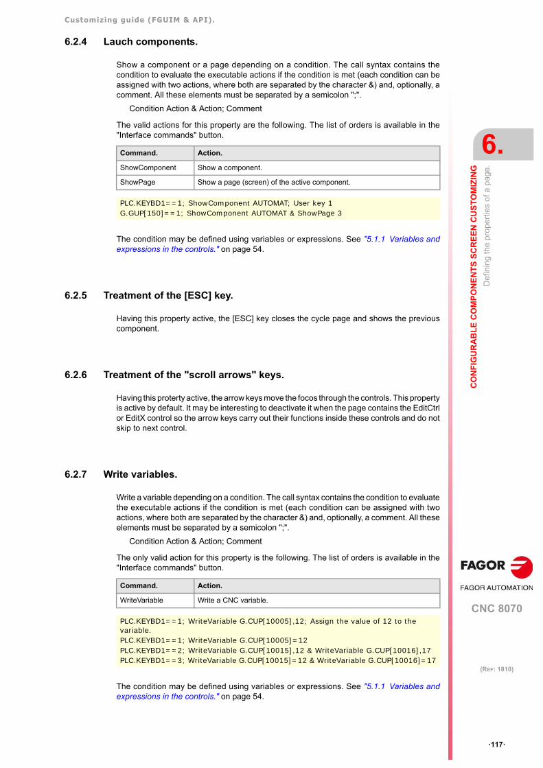
Customizing guide (FGUIM & API).
CNC 8070
CO
NF
IGU
RA
BL
E C
OM
PO
NE
NT
S S
CR
EE
N C
US
TO
MIZ
ING
6.
Def
inin
g th
e pr
oper
ties
of a
pa
ge.
·117·
(REF: 1810)
6.2.4 Lauch components.
Show a component or a page depending on a condition. The call syntax contains thecondition to evaluate the executable actions if the condition is met (each condition can beassigned with two actions, where both are separated by the character &) and, optionally, acomment. All these elements must be separated by a semicolon ";".
Condition Action & Action; Comment
The valid actions for this property are the following. The list of orders is available in the"Interface commands" button.
The condition may be defined using variables or expressions. See "5.1.1 Variables andexpressions in the controls." on page 54.
6.2.5 Treatment of the [ESC] key.
Having this property active, the [ESC] key closes the cycle page and shows the previouscomponent.
6.2.6 Treatment of the "scroll arrows" keys.
Having this proterty active, the arrow keys move the focos through the controls. This propertyis active by default. It may be interesting to deactivate it when the page contains the EditCtrlor EditX control so the arrow keys carry out their functions inside these controls and do notskip to next control.
6.2.7 Write variables.
Write a variable depending on a condition. The call syntax contains the condition to evaluatethe executable actions if the condition is met (each condition can be assigned with twoactions, where both are separated by the character &) and, optionally, a comment. All theseelements must be separated by a semicolon ";".
Condition Action & Action; Comment
The only valid action for this property is the following. The list of orders is available in the"Interface commands" button.
The condition may be defined using variables or expressions. See "5.1.1 Variables andexpressions in the controls." on page 54.
Command. Action.
ShowComponent Show a component.
ShowPage Show a page (screen) of the active component.
PLC.KEYBD1==1; ShowComponent AUTOMAT; User key 1G.GUP[150]==1; ShowComponent AUTOMAT & ShowPage 3
Command. Action.
WriteVariable Write a CNC variable.
PLC.KEYBD1==1; WriteVariable G.CUP[10005],12; Assign the value of 12 to the variable.PLC.KEYBD1==1; WriteVariable G.CUP[10005]=12PLC.KEYBD1==2; WriteVariable G.CUP[10015],12 & WriteVariable G.CUP[10016],17PLC.KEYBD1==3; WriteVariable G.CUP[10015]=12 & WriteVariable G.CUP[10016]=17
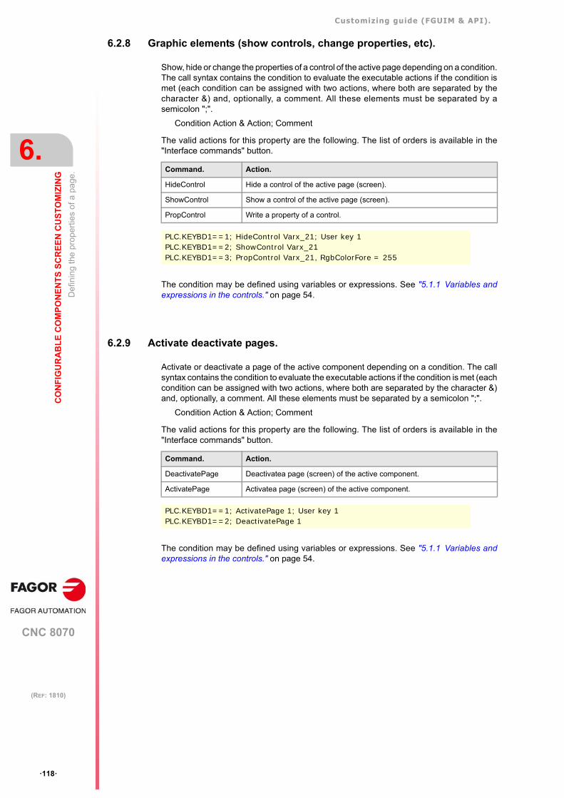
Customizing guide (FGUIM & API).
CNC 8070
6.
CO
NF
IGU
RA
BL
E C
OM
PO
NE
NT
S S
CR
EE
N C
US
TO
MIZ
ING
Def
inin
g th
e pr
oper
ties
of a
pa
ge.
·118·
(REF: 1810)
6.2.8 Graphic elements (show controls, change properties, etc).
Show, hide or change the properties of a control of the active page depending on a condition.The call syntax contains the condition to evaluate the executable actions if the condition ismet (each condition can be assigned with two actions, where both are separated by thecharacter &) and, optionally, a comment. All these elements must be separated by asemicolon ";".
Condition Action & Action; Comment
The valid actions for this property are the following. The list of orders is available in the"Interface commands" button.
The condition may be defined using variables or expressions. See "5.1.1 Variables andexpressions in the controls." on page 54.
6.2.9 Activate deactivate pages.
Activate or deactivate a page of the active component depending on a condition. The callsyntax contains the condition to evaluate the executable actions if the condition is met (eachcondition can be assigned with two actions, where both are separated by the character &)and, optionally, a comment. All these elements must be separated by a semicolon ";".
Condition Action & Action; Comment
The valid actions for this property are the following. The list of orders is available in the"Interface commands" button.
The condition may be defined using variables or expressions. See "5.1.1 Variables andexpressions in the controls." on page 54.
Command. Action.
HideControl Hide a control of the active page (screen).
ShowControl Show a control of the active page (screen).
PropControl Write a property of a control.
PLC.KEYBD1==1; HideControl Varx_21; User key 1PLC.KEYBD1==2; ShowControl Varx_21PLC.KEYBD1==3; PropControl Varx_21, RgbColorFore = 255
Command. Action.
DeactivatePage Deactivatea page (screen) of the active component.
ActivatePage Activatea page (screen) of the active component.
PLC.KEYBD1==1; ActivatePage 1; User key 1PLC.KEYBD1==2; DeactivatePage 1
Customizing guide (FGUIM & API).
CNC 8070
CO
NF
IGU
RA
BL
E C
OM
PO
NE
NT
S S
CR
EE
N C
US
TO
MIZ
ING
6.
Def
inin
g th
e pr
oper
ties
of a
pa
ge.
·119·
(REF: 1810)
6.2.10 Programming assistance.
"Interface commands" button.
This button shows the list of commands of the interface that allow handling the components,pages and controls. The selected command is inserted in the window that was selected whenpressing the button. Not all the windows admit all the commands. See "6.3 Interfaceoperation commands." on page 120.
"Variables" button.
This button shows the list of CNC variables that serves as programming assistance for theconditions and the "WriteVariable" command. The selected variable is inserted in the windowthat was selected when pressing the button.
"Components" button.
This button shows the list of CNC components that serves as programming assistance forthe "ShowComponent" command. The selected component is inserted in the window thatwas selected when pressing the button.
"Controls" button.
This button shows the list of the controls defined on the page that serves as programmingassistance for commands "ShowControl", "HideControl" and "PropControl". The selectedcontrol is inserted in the window that was selected when pressing the button.
"Properties" button.
This button shows the list of control properties selected on the list of controls ("Controls"button) that serves as programming assistance for the "PropControl" command. Theselected property is inserted in the window that was selected when pressing the button.
If no control has been selected, the button shows the properties of the first control of the pagein alphabetical order. The button itself shows the name of the control whose properties willbe displayed.
"Color dialog" button.
This button shows the color pallet that serves as programming assistance for the"PropControl" command when the control property is a color. The selected color is insertedin the window that was selected when pressing the button.
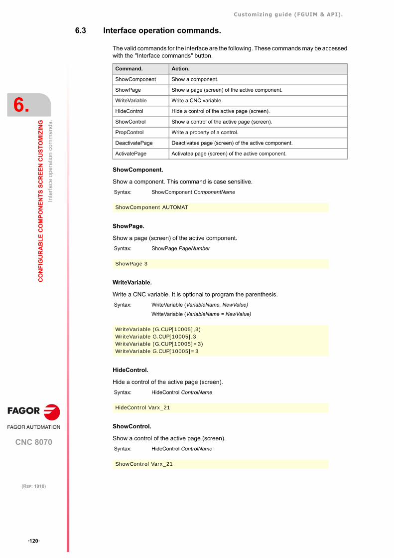
Customizing guide (FGUIM & API).
CNC 8070
6.
CO
NF
IGU
RA
BL
E C
OM
PO
NE
NT
S S
CR
EE
N C
US
TO
MIZ
ING
Inte
rfa
ce o
pera
tion
com
ma
nds.
·120·
(REF: 1810)
6.3 Interface operation commands.
The valid commands for the interface are the following. These commands may be accessedwith the "Interface commands" button.
ShowComponent.
Show a component. This command is case sensitive.
ShowPage.
Show a page (screen) of the active component.
WriteVariable.
Write a CNC variable. It is optional to program the parenthesis.
HideControl.
Hide a control of the active page (screen).
ShowControl.
Show a control of the active page (screen).
Command. Action.
ShowComponent Show a component.
ShowPage Show a page (screen) of the active component.
WriteVariable Write a CNC variable.
HideControl Hide a control of the active page (screen).
ShowControl Show a control of the active page (screen).
PropControl Write a property of a control.
DeactivatePage Deactivatea page (screen) of the active component.
ActivatePage Activatea page (screen) of the active component.
Syntax: ShowComponent ComponentName
ShowComponent AUTOMAT
Syntax: ShowPage PageNumber
ShowPage 3
Syntax: WriteVariable (VariableName, NewValue)
WriteVariable (VariableName = NewValue)
WriteVariable (G.CUP[10005],3)WriteVariable G.CUP[10005],3WriteVariable (G.CUP[10005]=3)WriteVariable G.CUP[10005]=3
Syntax: HideControl ControlName
HideControl Varx_21
Syntax: HideControl ControlName
ShowControl Varx_21
Customizing guide (FGUIM & API).
CNC 8070
CO
NF
IGU
RA
BL
E C
OM
PO
NE
NT
S S
CR
EE
N C
US
TO
MIZ
ING
6.
Inte
rfa
ce o
pera
tion
com
ma
nds.
·121·
(REF: 1810)
PropControl.
Write a property of a control, e.g. the text, the image, the variable that it displays or its color.It is optional to program the parenthesis.
The value can be a number in the numeric properties, True or False value in Booleanproperties and a text in text properties (text, name of variables). In the numeric properties(type: 0 - left, 1 - center, 2 - right) you must write the number.
In color properties, you must define the number associated with the color according to theRGB (Red, Green, Blue) code. A 3-byte hexadecimal number corresponds to each color ofthe code; the least significant bit for red, the second byte for green and the third byte for blue.
ActivatePage.
Activatea page (screen) of the active component. The active pages are the ones that maybe accessed when browsing through them.
Activating a page does not mean that it will be displayed when executing it; the command"ShowPage" must be executed in order to display the page.
To activate or deactivate a page in a component, it must be indicated in all pages of thatcomponent, in the properties of the pages or in the controls Multistatic and Button that areinserted in them.
DeactivatePage.
Deactivatea page (screen) of the active component. The deactivated pages cannot beaccessed when browsing through them; when deactivating a page, the total number of pagesof the component is smaller.
To activate or deactivate a page in a component, it must be indicated in all pages of thatcomponent, in the properties of the pages or in the controls Multistatic and Button that areinserted in them.
Syntax: PropControl (ControlName, PropertyName, NewValue)
PropControl (ControlName, PropertyName = NewValue)
PropControl Multistatic_1, rgbColorBack=16711680PropControl Button_1, ShadeMode=1
Syntax: ActivatePage PageNumber
ActivatePage 2
Syntax: DeactivatePage PageNumber
DeactivatePage 2
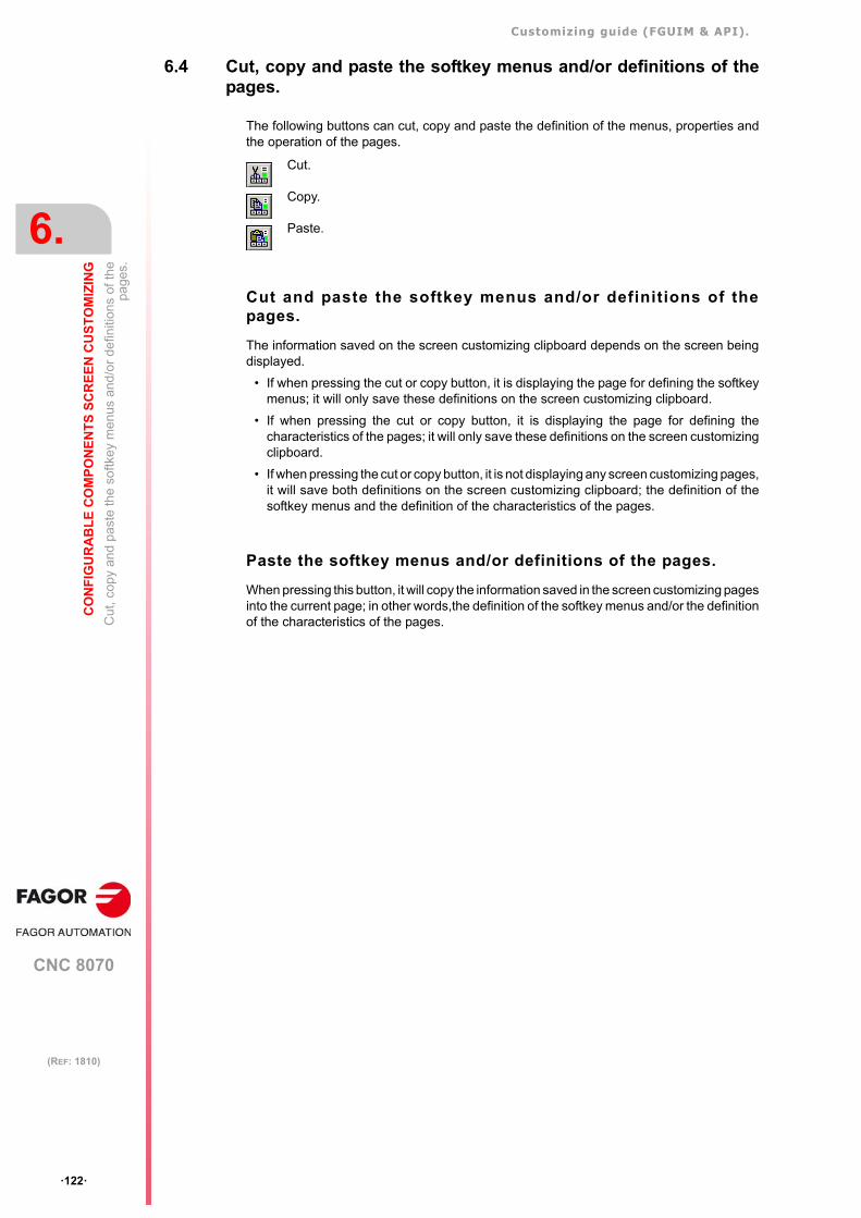
Customizing guide (FGUIM & API).
CNC 8070
6.
CO
NF
IGU
RA
BL
E C
OM
PO
NE
NT
S S
CR
EE
N C
US
TO
MIZ
ING
Cut
, cop
y an
d p
aste
the
sof
tkey
me
nus
and
/or
defin
ition
s of
the
page
s.
·122·
(REF: 1810)
6.4 Cut, copy and paste the softkey menus and/or definitions of thepages.
The following buttons can cut, copy and paste the definition of the menus, properties andthe operation of the pages.
Cut and paste the softkey menus and/or definitions of thepages.
The information saved on the screen customizing clipboard depends on the screen beingdisplayed.
• If when pressing the cut or copy button, it is displaying the page for defining the softkeymenus; it will only save these definitions on the screen customizing clipboard.
• If when pressing the cut or copy button, it is displaying the page for defining thecharacteristics of the pages; it will only save these definitions on the screen customizingclipboard.
• If when pressing the cut or copy button, it is not displaying any screen customizing pages,it will save both definitions on the screen customizing clipboard; the definition of thesoftkey menus and the definition of the characteristics of the pages.
Paste the softkey menus and/or definitions of the pages.
When pressing this button, it will copy the information saved in the screen customizing pagesinto the current page; in other words,the definition of the softkey menus and/or the definitionof the characteristics of the pages.
Cut.
Copy.
Paste.
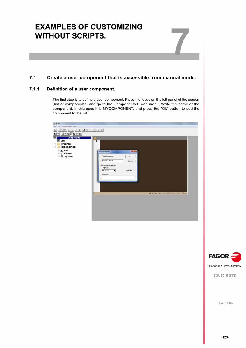
CNC 8070
7
·123·
(REF: 1810)
7. EXAMPLES OF CUSTOMIZING WITHOUT SCRIPTS.
7.1 Create a user component that is accessible from manual mode.
7.1.1 Definition of a user component.
The first step is to define a user component. Place the focus on the left panel of the screen(list of components) and go to the Components > Add menu. Write the name of thecomponent, in this case it is MYCOMPONENT, and press the "Ok" button to add thecomponent to the list.
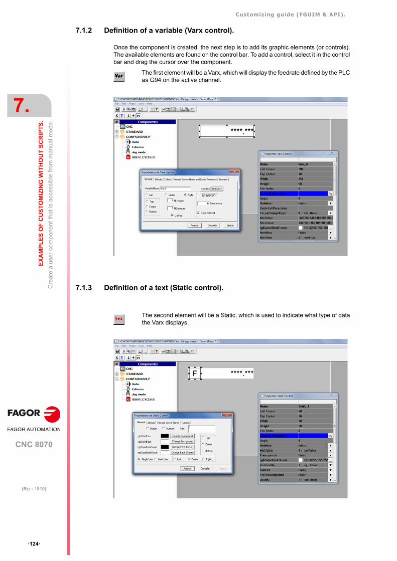
Customizing guide (FGUIM & API).
CNC 8070
7.
EX
AM
PL
ES
OF
CU
ST
OM
IZIN
G W
ITH
OU
T S
CR
IPT
S.
Cre
ate
a us
er c
om
pone
nt th
at is
acc
essi
ble
from
ma
nua
l mo
de.
·124·
(REF: 1810)
7.1.2 Definition of a variable (Varx control).
Once the component is created, the next step is to add its graphic elements (or controls).The available elements are found on the control bar. To add a control, select it in the controlbar and drag the cursor over the component.
7.1.3 Definition of a text (Static control).
The first element will be a Varx, which will display the feedrate defined by the PLCas G94 on the active channel.
The second element will be a Static, which is used to indicate what type of datathe Varx displays.
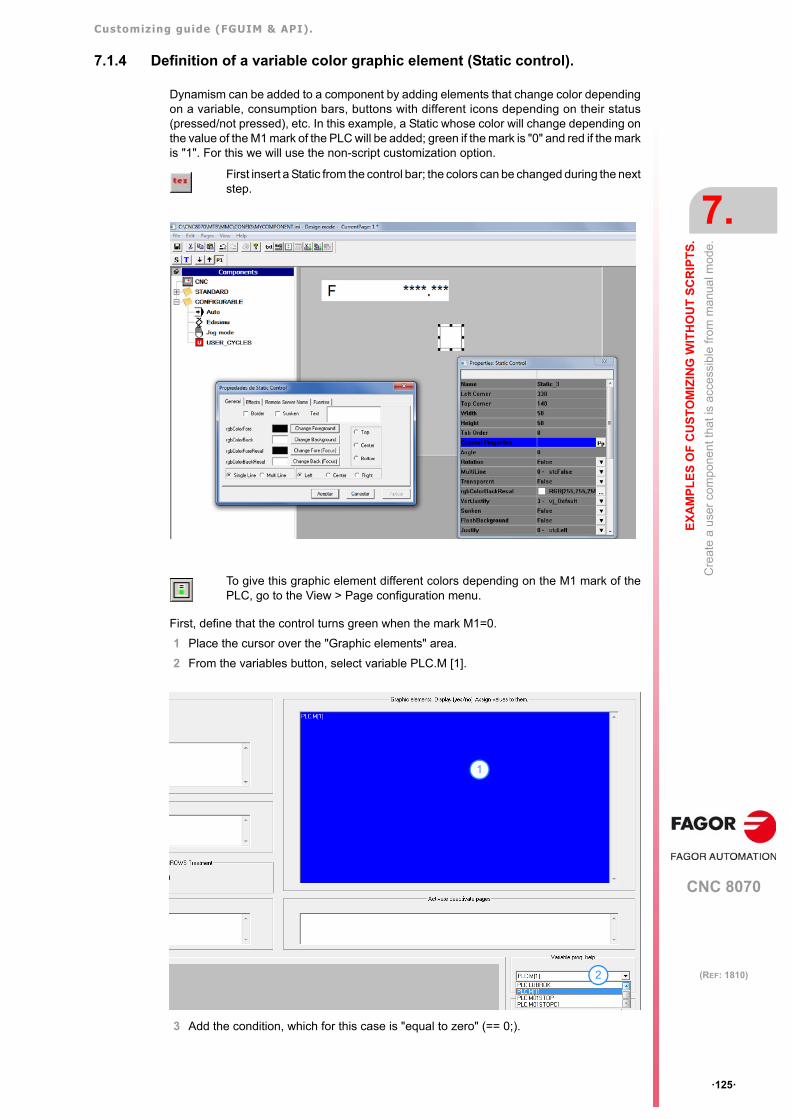
Customizing guide (FGUIM & API).
CNC 8070
EX
AM
PL
ES
OF
CU
ST
OM
IZIN
G W
ITH
OU
T S
CR
IPT
S.
7.
Cre
ate
a us
er c
om
pone
nt th
at is
acc
essi
ble
from
ma
nua
l mo
de.
·125·
(REF: 1810)
7.1.4 Definition of a variable color graphic element (Static control).
Dynamism can be added to a component by adding elements that change color dependingon a variable, consumption bars, buttons with different icons depending on their status(pressed/not pressed), etc. In this example, a Static whose color will change depending onthe value of the M1 mark of the PLC will be added; green if the mark is "0" and red if the markis "1". For this we will use the non-script customization option.
First, define that the control turns green when the mark M1=0.
1 Place the cursor over the "Graphic elements" area.
2 From the variables button, select variable PLC.M [1].
3 Add the condition, which for this case is "equal to zero" (== 0;).
First insert a Static from the control bar; the colors can be changed during the nextstep.
To give this graphic element different colors depending on the M1 mark of thePLC, go to the View > Page configuration menu.
1
2
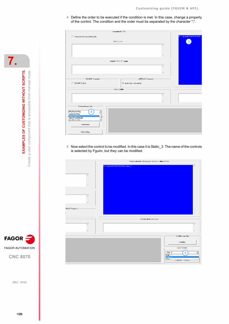
Customizing guide (FGUIM & API).
CNC 8070
7.
EX
AM
PL
ES
OF
CU
ST
OM
IZIN
G W
ITH
OU
T S
CR
IPT
S.
Cre
ate
a us
er c
om
pone
nt th
at is
acc
essi
ble
from
ma
nua
l mo
de.
·126·
(REF: 1810)
4 Define the order to be executed if the condition is met. In this case, change a propertyof the control. The condition and the order must be separated by the character ";".
5 Now select the control to be modified. In this case it is Static_3. The name of the controlsis selected by Fguim, but they can be modified.
3
4
5
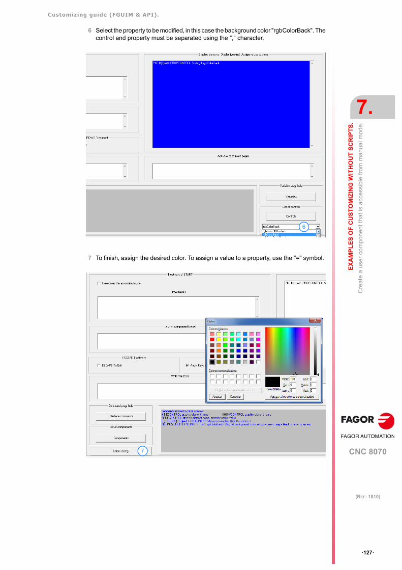
Customizing guide (FGUIM & API).
CNC 8070
EX
AM
PL
ES
OF
CU
ST
OM
IZIN
G W
ITH
OU
T S
CR
IPT
S.
7.
Cre
ate
a us
er c
om
pone
nt th
at is
acc
essi
ble
from
ma
nua
l mo
de.
·127·
(REF: 1810)
6 Select the property to be modified, in this case the background color "rgbColorBack". Thecontrol and property must be separated using the "," character.
7 To finish, assign the desired color. To assign a value to a property, use the "=" symbol.
6
7
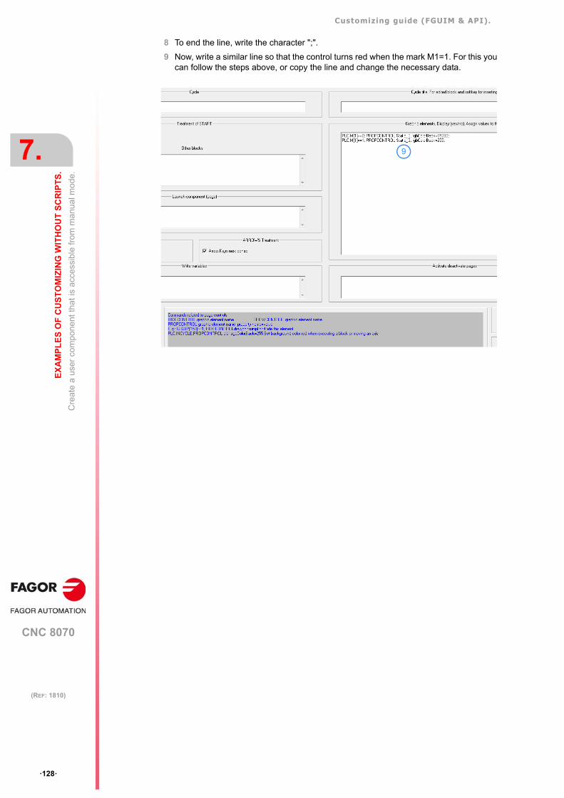
Customizing guide (FGUIM & API).
CNC 8070
7.
EX
AM
PL
ES
OF
CU
ST
OM
IZIN
G W
ITH
OU
T S
CR
IPT
S.
Cre
ate
a us
er c
om
pone
nt th
at is
acc
essi
ble
from
ma
nua
l mo
de.
·128·
(REF: 1810)
8 To end the line, write the character ";".
9 Now, write a similar line so that the control turns red when the mark M1=1. For this youcan follow the steps above, or copy the line and change the necessary data.
9
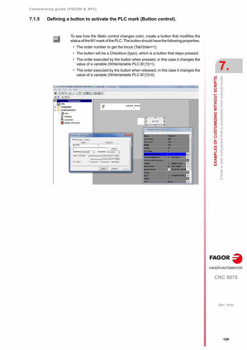
Customizing guide (FGUIM & API).
CNC 8070
EX
AM
PL
ES
OF
CU
ST
OM
IZIN
G W
ITH
OU
T S
CR
IPT
S.
7.
Cre
ate
a us
er c
om
pone
nt th
at is
acc
essi
ble
from
ma
nua
l mo
de.
·129·
(REF: 1810)
7.1.5 Defining a button to activate the PLC mark (Button control).
To see how the Static control changes color, create a button that modifies thestatus of the M1 mark of the PLC. The button should have the following properties.
• The order number to get the focus (TabOrder=1).
• The button will be a Checkbox (type), which is a button that stays pressed.
• The order executed by the button when pressed, in this case it changes thevalue of a variable (WriteVariable PLC.M [1]=1).
• The order executed by the button when released, in this case it changes thevalue of a variable (WriteVariable PLC.M [1]=0).
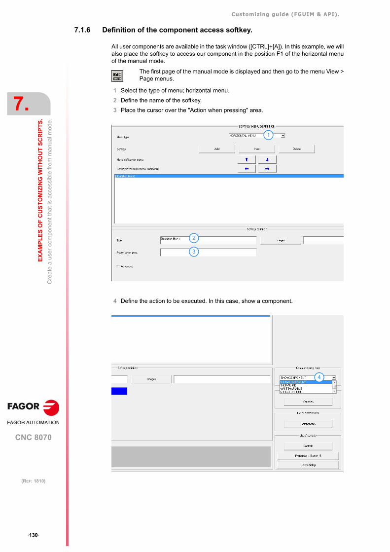
Customizing guide (FGUIM & API).
CNC 8070
7.
EX
AM
PL
ES
OF
CU
ST
OM
IZIN
G W
ITH
OU
T S
CR
IPT
S.
Cre
ate
a us
er c
om
pone
nt th
at is
acc
essi
ble
from
ma
nua
l mo
de.
·130·
(REF: 1810)
7.1.6 Definition of the component access softkey.
All user components are available in the task window ([CTRL]+[A]). In this example, we willalso place the softkey to access our component in the position F1 of the horizontal menuof the manual mode.
1 Select the type of menu; horizontal menu.
2 Define the name of the softkey.
3 Place the cursor over the "Action when pressing" area.
4 Define the action to be executed. In this case, show a component.
The first page of the manual mode is displayed and then go to the menu View >Page menus.
1
2
3
4
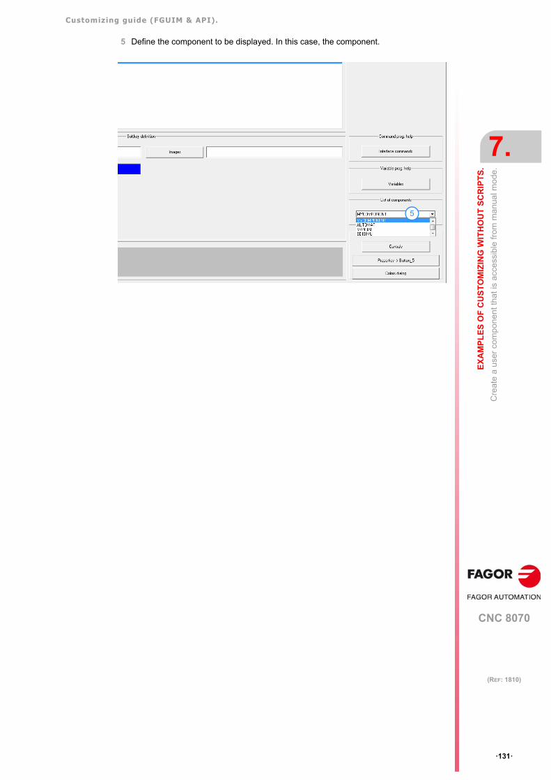
Customizing guide (FGUIM & API).
CNC 8070
EX
AM
PL
ES
OF
CU
ST
OM
IZIN
G W
ITH
OU
T S
CR
IPT
S.
7.
Cre
ate
a us
er c
om
pone
nt th
at is
acc
essi
ble
from
ma
nua
l mo
de.
·131·
(REF: 1810)
5 Define the component to be displayed. In this case, the component.
5
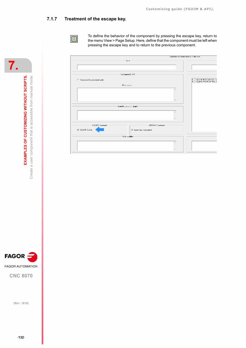
Customizing guide (FGUIM & API).
CNC 8070
7.
EX
AM
PL
ES
OF
CU
ST
OM
IZIN
G W
ITH
OU
T S
CR
IPT
S.
Cre
ate
a us
er c
om
pone
nt th
at is
acc
essi
ble
from
ma
nua
l mo
de.
·132·
(REF: 1810)
7.1.7 Treatment of the escape key.
To define the behavior of the component by pressing the escape key, return tothe menu View > Page Setup. Here, define that the component must be left whenpressing the escape key and to return to the previous component.
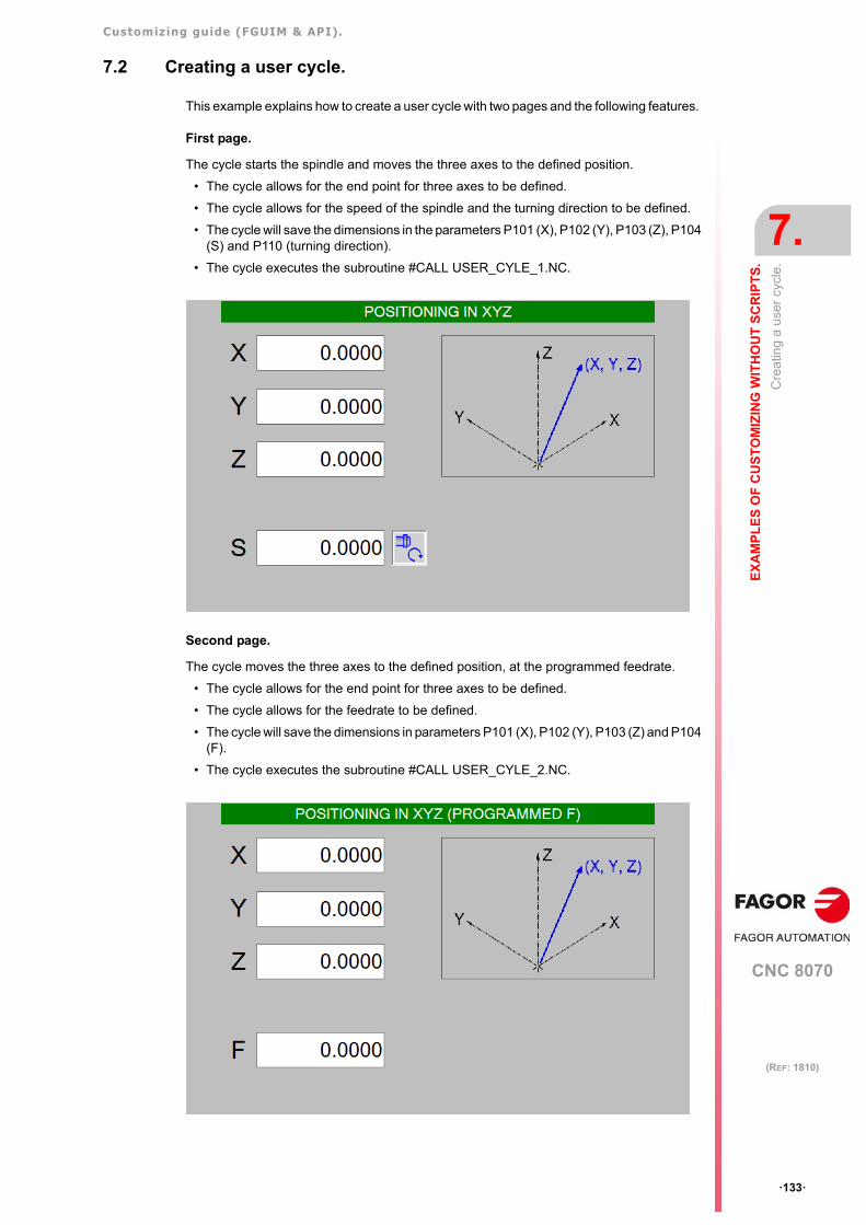
Customizing guide (FGUIM & API).
CNC 8070
EX
AM
PL
ES
OF
CU
ST
OM
IZIN
G W
ITH
OU
T S
CR
IPT
S.
7.
Cre
atin
g a
user
cyc
le.
·133·
(REF: 1810)
7.2 Creating a user cycle.
This example explains how to create a user cycle with two pages and the following features.
First page.
The cycle starts the spindle and moves the three axes to the defined position.
• The cycle allows for the end point for three axes to be defined.
• The cycle allows for the speed of the spindle and the turning direction to be defined.
• The cycle will save the dimensions in the parameters P101 (X), P102 (Y), P103 (Z), P104(S) and P110 (turning direction).
• The cycle executes the subroutine #CALL USER_CYLE_1.NC.
Second page.
The cycle moves the three axes to the defined position, at the programmed feedrate.
• The cycle allows for the end point for three axes to be defined.
• The cycle allows for the feedrate to be defined.
• The cycle will save the dimensions in parameters P101 (X), P102 (Y), P103 (Z) and P104(F).
• The cycle executes the subroutine #CALL USER_CYLE_2.NC.
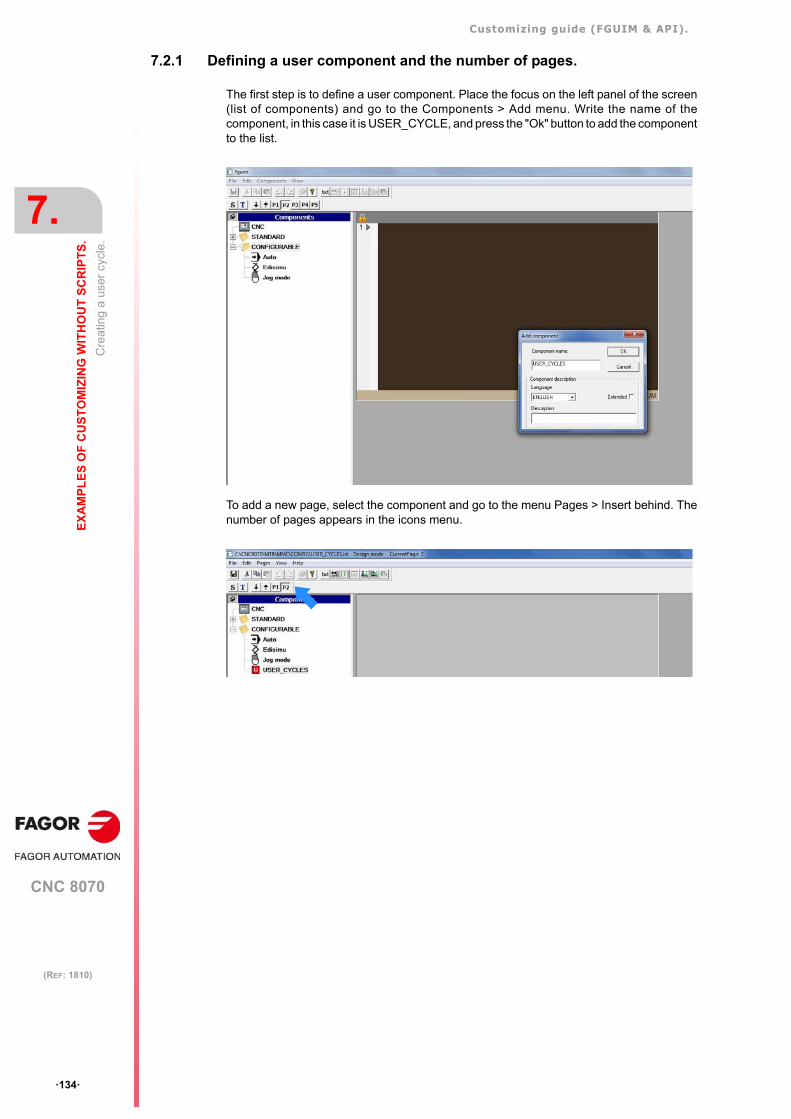
Customizing guide (FGUIM & API).
CNC 8070
7.
EX
AM
PL
ES
OF
CU
ST
OM
IZIN
G W
ITH
OU
T S
CR
IPT
S.
Cre
atin
g a
user
cyc
le.
·134·
(REF: 1810)
7.2.1 Defining a user component and the number of pages.
The first step is to define a user component. Place the focus on the left panel of the screen(list of components) and go to the Components > Add menu. Write the name of thecomponent, in this case it is USER_CYCLE, and press the "Ok" button to add the componentto the list.
To add a new page, select the component and go to the menu Pages > Insert behind. Thenumber of pages appears in the icons menu.
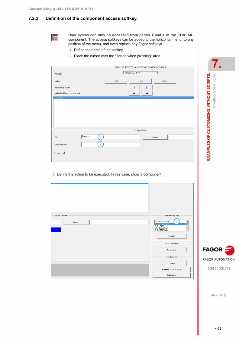
Customizing guide (FGUIM & API).
CNC 8070
EX
AM
PL
ES
OF
CU
ST
OM
IZIN
G W
ITH
OU
T S
CR
IPT
S.
7.
Cre
atin
g a
user
cyc
le.
·135·
(REF: 1810)
7.2.2 Definition of the component access softkey.
3 Define the action to be executed. In this case, show a component.
User cycles can only be accessed from pages 1 and 4 of the EDISIMUcomponent. The access softkeys can be added to the horizontal menu, to anyposition of the menu, and even replace any Fagor softkeys.
1 Define the name of the softkey.
2 Place the cursor over the "Action when pressing" area.
1
2
3
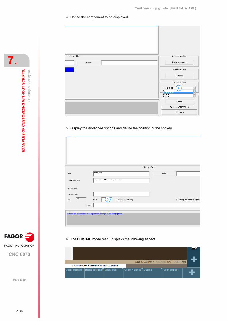
Customizing guide (FGUIM & API).
CNC 8070
7.
EX
AM
PL
ES
OF
CU
ST
OM
IZIN
G W
ITH
OU
T S
CR
IPT
S.
Cre
atin
g a
user
cyc
le.
·136·
(REF: 1810)
4 Define the component to be displayed.
5 Display the advanced options and define the position of the softkey.
6 The EDISIMU mode menu displays the following aspect.
4
5
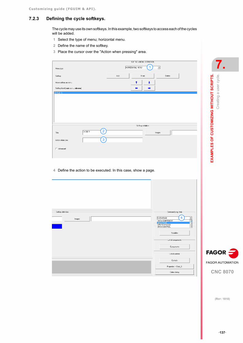
Customizing guide (FGUIM & API).
CNC 8070
EX
AM
PL
ES
OF
CU
ST
OM
IZIN
G W
ITH
OU
T S
CR
IPT
S.
7.
Cre
atin
g a
user
cyc
le.
·137·
(REF: 1810)
7.2.3 Defining the cycle softkeys.
The cycle may use its own softkeys. In this example, two softkeys to access each of the cycleswill be added.
1 Select the type of menu; horizontal menu.
2 Define the name of the softkey.
3 Place the cursor over the "Action when pressing" area.
4 Define the action to be executed. In this case, show a page.
1
2
3
4
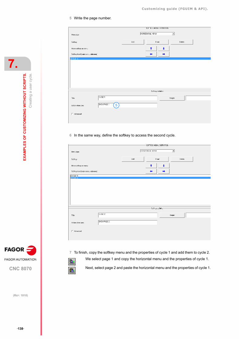
Customizing guide (FGUIM & API).
CNC 8070
7.
EX
AM
PL
ES
OF
CU
ST
OM
IZIN
G W
ITH
OU
T S
CR
IPT
S.
Cre
atin
g a
user
cyc
le.
·138·
(REF: 1810)
5 Write the page number.
6 In the same way, define the softkey to access the second cycle.
7 To finish, copy the softkey menu and the properties of cycle 1 and add them to cycle 2.
We select page 1 and copy the horizontal menu and the properties of cycle 1.
Next, select page 2 and paste the horizontal menu and the properties of cycle 1.
5
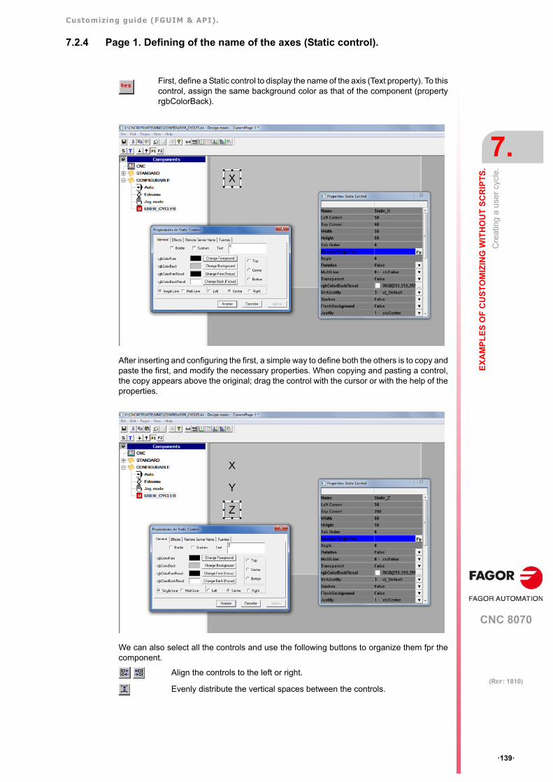
Customizing guide (FGUIM & API).
CNC 8070
EX
AM
PL
ES
OF
CU
ST
OM
IZIN
G W
ITH
OU
T S
CR
IPT
S.
7.
Cre
atin
g a
user
cyc
le.
·139·
(REF: 1810)
7.2.4 Page 1. Defining of the name of the axes (Static control).
After inserting and configuring the first, a simple way to define both the others is to copy andpaste the first, and modify the necessary properties. When copying and pasting a control,the copy appears above the original; drag the control with the cursor or with the help of theproperties.
We can also select all the controls and use the following buttons to organize them fpr thecomponent.
First, define a Static control to display the name of the axis (Text property). To thiscontrol, assign the same background color as that of the component (propertyrgbColorBack).
Align the controls to the left or right.
Evenly distribute the vertical spaces between the controls.
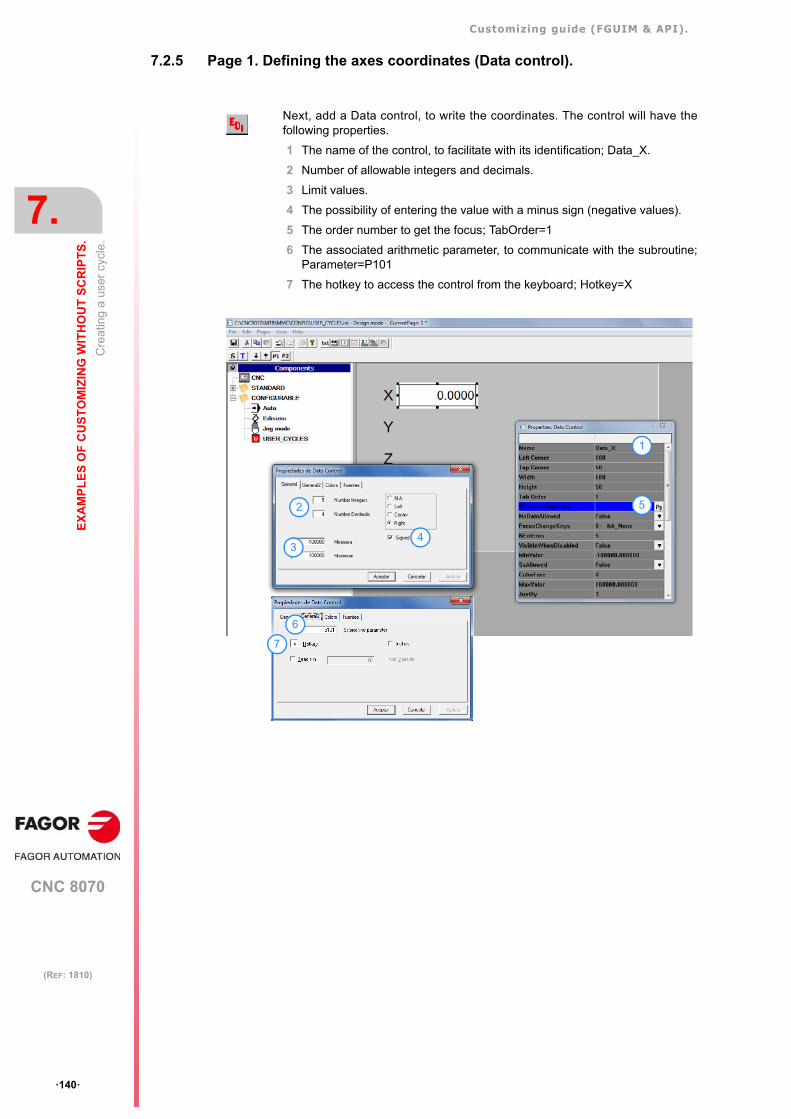
Customizing guide (FGUIM & API).
CNC 8070
7.
EX
AM
PL
ES
OF
CU
ST
OM
IZIN
G W
ITH
OU
T S
CR
IPT
S.
Cre
atin
g a
user
cyc
le.
·140·
(REF: 1810)
7.2.5 Page 1. Defining the axes coordinates (Data control).
Next, add a Data control, to write the coordinates. The control will have thefollowing properties.
1 The name of the control, to facilitate with its identification; Data_X.
2 Number of allowable integers and decimals.
3 Limit values.
4 The possibility of entering the value with a minus sign (negative values).
5 The order number to get the focus; TabOrder=1
6 The associated arithmetic parameter, to communicate with the subroutine;Parameter=P101
7 The hotkey to access the control from the keyboard; Hotkey=X
1
7
2
4
5
6
3
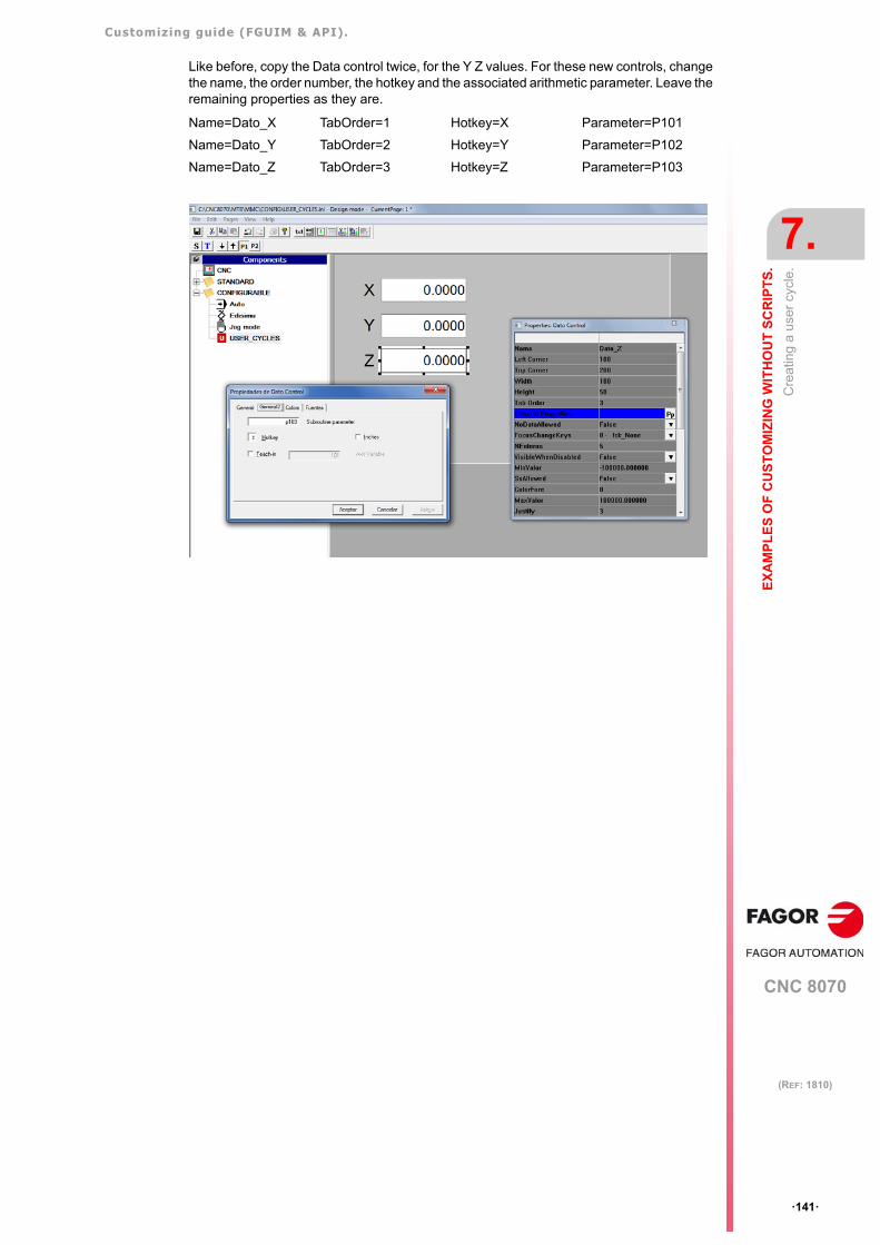
Customizing guide (FGUIM & API).
CNC 8070
EX
AM
PL
ES
OF
CU
ST
OM
IZIN
G W
ITH
OU
T S
CR
IPT
S.
7.
Cre
atin
g a
user
cyc
le.
·141·
(REF: 1810)
Like before, copy the Data control twice, for the Y Z values. For these new controls, changethe name, the order number, the hotkey and the associated arithmetic parameter. Leave theremaining properties as they are.
Name=Dato_X TabOrder=1 Hotkey=X Parameter=P101
Name=Dato_Y TabOrder=2 Hotkey=Y Parameter=P102
Name=Dato_Z TabOrder=3 Hotkey=Z Parameter=P103
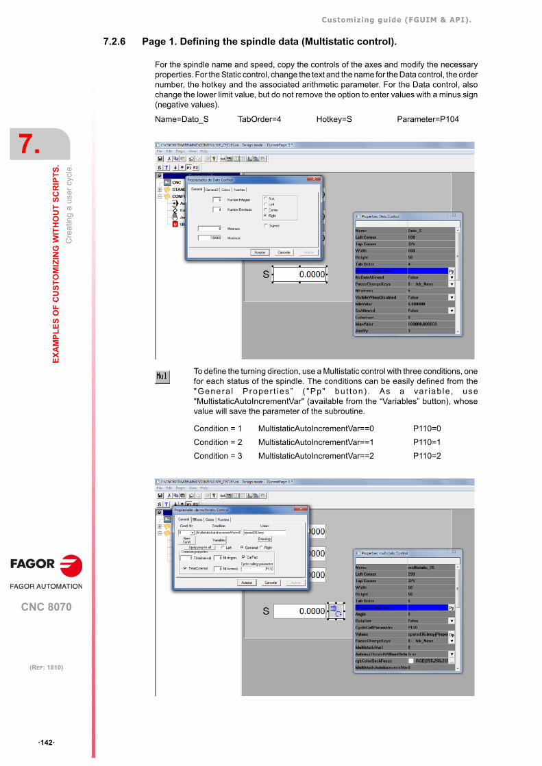
Customizing guide (FGUIM & API).
CNC 8070
7.
EX
AM
PL
ES
OF
CU
ST
OM
IZIN
G W
ITH
OU
T S
CR
IPT
S.
Cre
atin
g a
user
cyc
le.
·142·
(REF: 1810)
7.2.6 Page 1. Defining the spindle data (Multistatic control).
For the spindle name and speed, copy the controls of the axes and modify the necessaryproperties. For the Static control, change the text and the name for the Data control, the ordernumber, the hotkey and the associated arithmetic parameter. For the Data control, alsochange the lower limit value, but do not remove the option to enter values with a minus sign(negative values).
Name=Dato_S TabOrder=4 Hotkey=S Parameter=P104
To define the turning direction, use a Multistatic control with three conditions, onefor each status of the spindle. The conditions can be easily defined from the"Genera l P roper t ies ” ( "Pp" bu t ton) . As a va r iab le , use"MultistaticAutoIncrementVar" (available from the “Variables” button), whosevalue will save the parameter of the subroutine.
Condition = 1 MultistaticAutoIncrementVar==0 P110=0
Condition = 2 MultistaticAutoIncrementVar==1 P110=1
Condition = 3 MultistaticAutoIncrementVar==2 P110=2
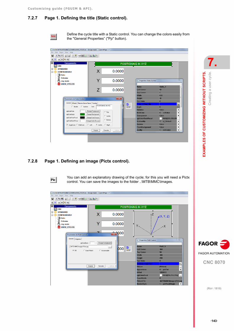
Customizing guide (FGUIM & API).
CNC 8070
EX
AM
PL
ES
OF
CU
ST
OM
IZIN
G W
ITH
OU
T S
CR
IPT
S.
7.
Cre
atin
g a
user
cyc
le.
·143·
(REF: 1810)
7.2.7 Page 1. Defining the title (Static control).
7.2.8 Page 1. Defining an image (Pictx control).
Define the cycle title with a Static control. You can change the colors easily fromthe "General Properties” ("Pp" button).
You can add an explanatory drawing of the cycle; for this you will need a Pictxcontrol. You can save the images to the folder ..\MTB\MMC\Images.
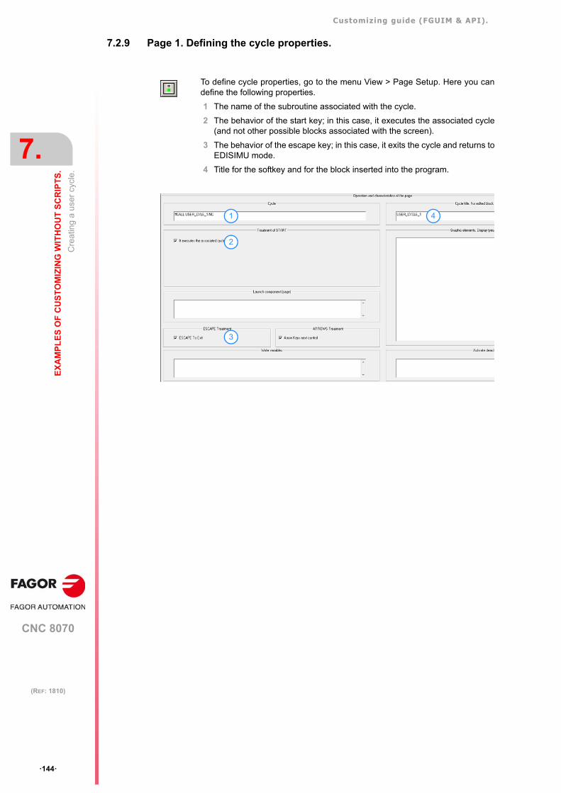
Customizing guide (FGUIM & API).
CNC 8070
7.
EX
AM
PL
ES
OF
CU
ST
OM
IZIN
G W
ITH
OU
T S
CR
IPT
S.
Cre
atin
g a
user
cyc
le.
·144·
(REF: 1810)
7.2.9 Page 1. Defining the cycle properties.
To define cycle properties, go to the menu View > Page Setup. Here you candefine the following properties.
1 The name of the subroutine associated with the cycle.
2 The behavior of the start key; in this case, it executes the associated cycle(and not other possible blocks associated with the screen).
3 The behavior of the escape key; in this case, it exits the cycle and returns toEDISIMU mode.
4 Title for the softkey and for the block inserted into the program.
1
2
3
4
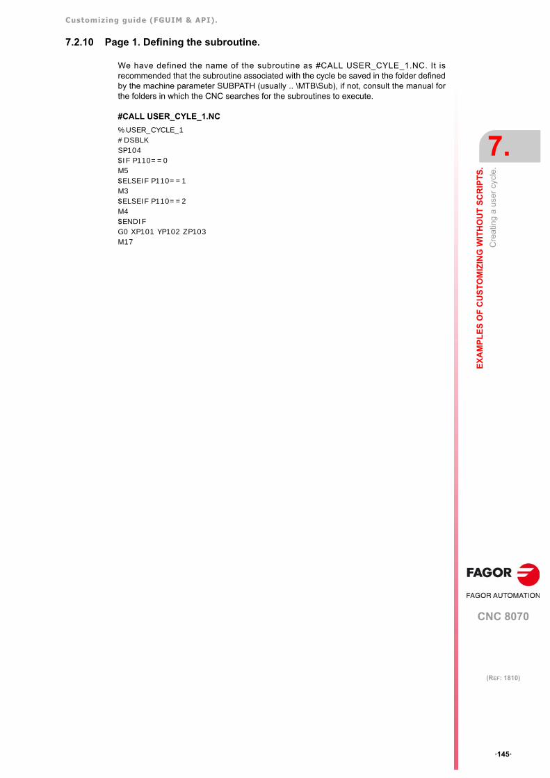
Customizing guide (FGUIM & API).
CNC 8070
EX
AM
PL
ES
OF
CU
ST
OM
IZIN
G W
ITH
OU
T S
CR
IPT
S.
7.
Cre
atin
g a
user
cyc
le.
·145·
(REF: 1810)
7.2.10 Page 1. Defining the subroutine.
We have defined the name of the subroutine as #CALL USER_CYLE_1.NC. It isrecommended that the subroutine associated with the cycle be saved in the folder definedby the machine parameter SUBPATH (usually .. \MTB\Sub), if not, consult the manual forthe folders in which the CNC searches for the subroutines to execute.
#CALL USER_CYLE_1.NC
%USER_CYCLE_1#DSBLKSP104$IF P110==0M5$ELSEIF P110==1M3$ELSEIF P110==2M4$ENDIFG0 XP101 YP102 ZP103 M17
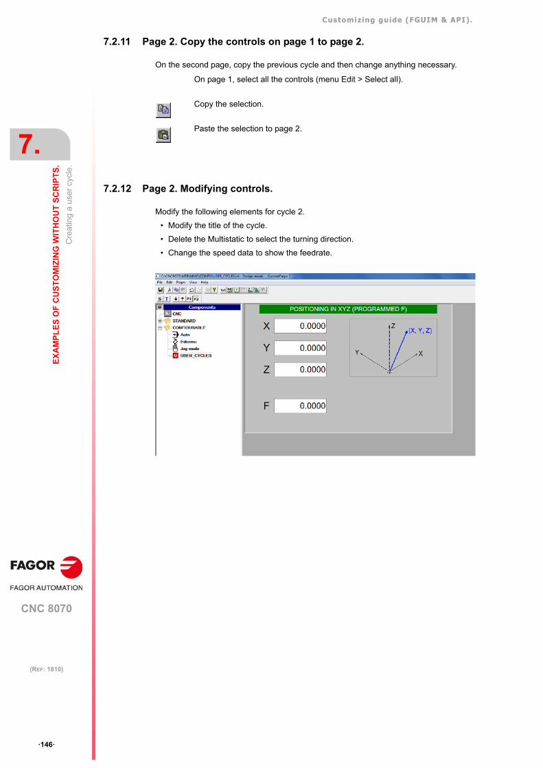
Customizing guide (FGUIM & API).
CNC 8070
7.
EX
AM
PL
ES
OF
CU
ST
OM
IZIN
G W
ITH
OU
T S
CR
IPT
S.
Cre
atin
g a
user
cyc
le.
·146·
(REF: 1810)
7.2.11 Page 2. Copy the controls on page 1 to page 2.
On the second page, copy the previous cycle and then change anything necessary.
7.2.12 Page 2. Modifying controls.
Modify the following elements for cycle 2.
• Modify the title of the cycle.
• Delete the Multistatic to select the turning direction.
• Change the speed data to show the feedrate.
On page 1, select all the controls (menu Edit > Select all).
Copy the selection.
Paste the selection to page 2.
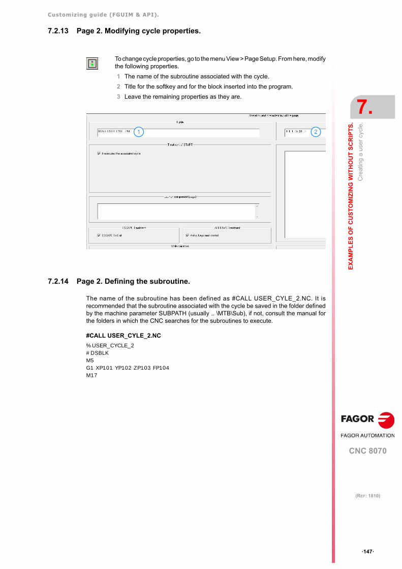
Customizing guide (FGUIM & API).
CNC 8070
EX
AM
PL
ES
OF
CU
ST
OM
IZIN
G W
ITH
OU
T S
CR
IPT
S.
7.
Cre
atin
g a
user
cyc
le.
·147·
(REF: 1810)
7.2.13 Page 2. Modifying cycle properties.
7.2.14 Page 2. Defining the subroutine.
The name of the subroutine has been defined as #CALL USER_CYLE_2.NC. It isrecommended that the subroutine associated with the cycle be saved in the folder definedby the machine parameter SUBPATH (usually .. \MTB\Sub), if not, consult the manual forthe folders in which the CNC searches for the subroutines to execute.
#CALL USER_CYLE_2.NC
%USER_CYCLE_2#DSBLKM5G1 XP101 YP102 ZP103 FP104M17
To change cycle properties, go to the menu View > Page Setup. From here, modifythe following properties.
1 The name of the subroutine associated with the cycle.
2 Title for the softkey and for the block inserted into the program.
3 Leave the remaining properties as they are.
1 2
Customizing guide (FGUIM & API).
CNC 8070
7.
EX
AM
PL
ES
OF
CU
ST
OM
IZIN
G W
ITH
OU
T S
CR
IPT
S.
Cre
atin
g a
user
cyc
le.
·148·
(REF: 1810)
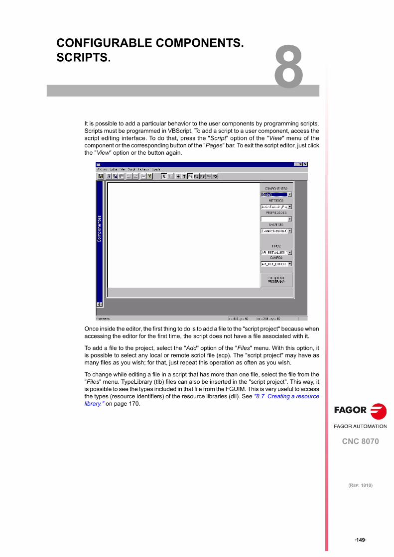
CNC 8070
8
·149·
(REF: 1810)
8. CONFIGURABLE COMPONENTS. SCRIPTS.
It is possible to add a particular behavior to the user components by programming scripts.Scripts must be programmed in VBScript. To add a script to a user component, access thescript editing interface. To do that, press the "Script" option of the "View" menu of thecomponent or the corresponding button of the "Pages" bar. To exit the script editor, just clickthe "View" option or the button again.
Once inside the editor, the first thing to do is to add a file to the "script project" because whenaccessing the editor for the first time, the script does not have a file associated with it.
To add a file to the project, select the "Add" option of the "Files" menu. With this option, itis possible to select any local or remote script file (scp). The "script project" may have asmany files as you wish; for that, just repeat this operation as often as you wish.
To change while editing a file in a script that has more than one file, select the file from the"Files" menu. TypeLibrary (tlb) files can also be inserted in the "script project". This way, itis possible to see the types included in that file from the FGUIM. This is very useful to accessthe types (resource identifiers) of the resource libraries (dll). See "8.7 Creating a resourcelibrary." on page 170.
Customizing guide (FGUIM & API).
CNC 8070
8.
CO
NF
IGU
RA
BL
E C
OM
PO
NE
NT
S. S
CR
IPT
S.
Scr
ipt p
rogr
amm
ing
assi
sta
nce.
·150·
(REF: 1810)
8.1 Script programming assistance.
To make script editing easier, there are some helps on the right side of the screen. The easiestway to use these elements is selecting from the proper list the method, property, etc. to beused and press [CTRL]+[Insert]. The selected value is inserted in the editor where the cursoris. In the case of events, it inserts the necessary code to create the event function.
Besides, the script editor has a button to check the syntax of the program.
Components.
It shows all the controls of the component (their names as they appear on the "name" propertyof the control) and the servers Global, Dialog, Menu, Window, kernel, variables and util.
The first four servers (Global, Dialog, Menu, Window) are specific of the scripts of thecomponents and are described in this chapter. See "8.3 Servers for the scripts." on page153. The last three (kernel, variables, util) are servers of the API8070. See "9.2 Servers ofthe API8070." on page 175.
Methods.
It shows the methods (COM functions) of the selected component.
Properties.
It shows the properties of the selected component.
Events.
It shows the events (warning functions) of the selected component.
Types.
It shows the various types used by the servers or the types used by the control of the selectedcomponent.
Fields.
Valid values of the selected type.
Customizing guide (FGUIM & API).
CNC 8070
CO
NF
IGU
RA
BL
E C
OM
PO
NE
NT
S. S
CR
IPT
S.
8.
Tex
ts in
diff
eren
t lan
gua
ges
in th
e s
crip
ts.
·151·
(REF: 1810)
8.2 Texts in different languages in the scripts.
The texts shown by a script may now be multilingual; in other words, that depending on thelanguage selected at the CNC, the texts may be displayed in that language.
Using files in different languages.
Generating files in languages.
The first step consists in creating the text files in the various languages. They must be scptype files and each one must have defined the texts that will be used from the script.
The texts defined in the files must be like "Identifier" = "Text". The identifiers will be used fromthe script.
Location of the files in languages.
Each text file must be in the relevant language directory (...\mtb \mmc \lang \language). Thefile with the texts of the active language must be in the directory ...\mtb \mmc \lang.
When changing the CNC language, the file of the active language (...\Mtb \mmc \lang) isreplaced by that of the corresponding language.
Insert the texts in the script.
The file with the texts must be inserted into the script. From the "Add" option of the "Files"menu, add the scp file that contains the texts. Add the text file that is in the active languagedirectory (...\Mtb \mmc \lang).
The defined identifiers are used in the script instead of using the texts directly,
For example, to use texts in Spanish and English, proceed as follows.
1 Create the file text.scp for Spanish castellano ( ...\Mtb \mmc \lang \spanish \text.scp) andEnglish (...\Mtb \mmc \lang \english \text.scp). The first one defines the texts in Spanish:
IDS_TEXT1 = "Primer texto"
And the second one in English:
IDS_TEXT1 = "First text"
2 One of the files is copied to the CNC directory of the active language ( ...\Mtb \mmc \lang\text.scp).
3 In the script, instead of using the texts directly, their defined identifiers are used.
Using the texts directly: msgbox "First text".
Using the identifiers: msgbox "msgbox IDS_TEXT1".
Using the text editor.
To make a text language dependent, instead of defining the text directly, define an identifierthat will be associated with the text to be shown.
Define the identifiers.
The text identifiers may have any name. As opposed to the identifiers of the controls, theseneed not begin with the prefix "IDS_".
The identifiers and the texts must be in a section with the name of the component that ownsthe script.
The text editor.
Once in the editor, its operation is very easy. Just select the language for the text and addlines like: "Identifier" = "Text".
Use the text editor of the FGUIM to associate the identifiers to the texts. To access the editor,select the Text editor" option of the "View" menu or the corresponding button.
Customizing guide (FGUIM & API).
CNC 8070
8.
CO
NF
IGU
RA
BL
E C
OM
PO
NE
NT
S. S
CR
IPT
S.
Tex
ts in
diff
eren
t lan
gua
ges
in th
e s
crip
ts.
·152·
(REF: 1810)
For example, to define texts in Spanish and English, proceed as follows.
1 Select the "Spanish" language at the editor and write the following.
[MANUAL SCRIPT]
MYTEXT1 = "Mi texto 1"
MYTEXT2 = "Mi texto 2"
[EDISIMU SCRIPT]
MYTEXT3 = "Mi texto 3"
2 Select the "English" language and write the following.
[MANUAL SCRIPT]
MYTEXT1 = "My text 1"
MYTEXT2 = "My text 2"
[EDISIMU SCRIPT]
MYTEXT3 = "My text 3"
Once the identifiers have been entered in the various languages, the identifiers may be usedin the scripts instead of the text.
Customizing guide (FGUIM & API).
CNC 8070
CO
NF
IGU
RA
BL
E C
OM
PO
NE
NT
S. S
CR
IPT
S.
8.
Se
rve
rs f
or th
e s
crip
ts.
·153·
(REF: 1810)
8.3 Servers for the scripts.
When programming the scripts, all the API8070 servers may be used although only someof them may be accessed from the FGUIM because not all their servers or functions makesense in the scripts (machine parameter server, functions such as InitKernel, CloseKernel,etc.). See "9.2 Servers of the API8070." on page 175.
Besides having the possibility of using all the servers of the API8070, some special serversmay also be used:
• See "–Global– server." on page 154.
• See "–Dialog– server." on page 166.
• See "–Menu– server." on page 168.
Customizing guide (FGUIM & API).
CNC 8070
8.
CO
NF
IGU
RA
BL
E C
OM
PO
NE
NT
S. S
CR
IPT
S.
–Glo
bal
– se
rver
.
·154·
(REF: 1810)
8.4 –Global– server.
To use the methods and properties of this server, it is not necessary to put the server namebefore the method.
Example: Global.Killtimer = KillTimer
However, it is required in the events (so as not to mistake them with normal functions).
8.4.1 Methods of the -Global- server
void NextPage()
It displays the next page of the component.
IDispatch* CreateControl(BSTR controlPropID, long xPos, long yPos, long width, longheight, long iTabStop, COLORREF bkColor)
It creates a control. It passes the progID, dimensions, tabulation sequence ("0" if it does notrequire the focus) and the background color of the control. To assign the control created toa variable of the script, use the instruction Setof VBScript.
If the control cannot be created, the function returns an error message.
void ShowControl(IDispatch* control, boolean bShow)
It displays or hides a control. The parameter to be defined will be the name of the control(property name) or if it has been created with CreateControl, the variable associated withthe control.
void MoveControl(IDispatch* control, long xPos, long yPos, long width, long height)
It changes the position or dimensions of a control.
void SetFocus(IDispatch* control)
It gives the focus to the indicated control. This function does not activate the control menu;it only gives the focus to it.
long SetTimer(long iEllapse)
It creates a timer (see EventTimer event of this server). The parameter indicates the timein ms that must elapse since the server launches an event until it launches the next one.
Each script may create a maximum of 10 timers. The returned value is the identifier of thetimer (used to close it in KillTimer or to identify the envent of the timer) or "0" if it could notbe created.
"Event called upon when pressing an option of the vertical menu.Sub Global_EventMenuV(menuID)End Sub
'EventMenuV function that does nothing.Sub EventMenuV(menuID)End Sub
Set myVarx = CreateControl ("Varx.VarxCtrl.1", 0,0, 100,20, 0, RGB(0,0,0))
ShowControl myVarx,false
MoveControl myVarx,22,22,200,400
SetFocus myVarxWindow
' 100 ms timer.SetTimer 100
Customizing guide (FGUIM & API).
CNC 8070
CO
NF
IGU
RA
BL
E C
OM
PO
NE
NT
S. S
CR
IPT
S.
8.
–Glo
bal
– se
rver
.
·155·
(REF: 1810)
boolean KillTimer(long idTimer)
It destroys the timer with idTimer identifier. If it was not created, it returns FALSE.
IPictureDisp* CreatePicture(BSTR picturePath)
It creates a Picture object from a drawing file (bmp, ico, etc.). This type of objects is interestingbecause some controls use them to display drawings (the Picture property of the PictXcontrol is of this type). If the object cannot be created, the function returns the empty object"Nothing".
IFontDisp* CreateFont(BSTR name, long size, FONT_WEIGHT_T weight,FONT_CHARSET_T sCharset, boolean italic, boolean underline, booleanstrikethrough)
It creates a Font object from a description. This type of objects is used from the controls,dialogs (see –Dialog– server), etc. If the object cannot be created, the function returns theempty object "Nothing".
IDispatch* InitResourceMenu(BSTR pathResourceDll, long menuID)
It creates a menu object (see –Menu– server) from a resource library and a menu identifierwithin the DLL. If the object cannot be created, the function returns the empty object"Nothing". See "8.7 Creating a resource library." on page 170.
IPictureDisp* CreatePictureResource(BSTR picturePath, long IDPicture)
It creates a Picture object from a resource library and a bitmap, icon, etc identifier within it.If the object cannot be created, the function returns the empty object "Nothing".
boolean DestroyControl(IDispatch* control)
It destroys a control. If the control already existed and it is destroyed, it returns TRUE,otherwise a FALSE.
BSTR LoadStringResource(BSTR resourcePath, long stringID)
It reads a string of the resource library (of its string_Table).
long GetPageNumber()
It returns the page of the component where we are.
Set myPicture = CreatePicture("c:\tmp\mypicture.bmp")If(Not myPict Is Nothing) Then Set MyPictX.Picture = myPicture
Set myFont =global.CreateFont ("Arial",8,BOLD,ANSI,True,True,True)If(Not myFont Is Nothing)Then mydialog.SetItemFont ITEM_ID,myFontSet myText.font = myFontEnd If
Note: BOLD is a FONT_WEIGHT_T type field and ANSI is of the FONT_CHARSET_T field. Thesetypes are shown on the Type list.
Set menu1 = InitResourceMenu ("c:\tmp\Resources.dll", MENU1_ID)If(Not menu1 Is Nothing) Then DisplayMenuV myMenu
Note: The menu1 variable must be defined out of the function where InitResourceMenu takes place(it must be a global variable) because when exiting that function it will release all its local variablesand destroy the dialog.
Set myPict= CreatePictureResource("c:\tmp\Resources.dll", ID_BITMAP1)If(Not myPict Is Nothing) Then Set MiPictX.Picture = myPicture
DestroyControl myVarx
Text1 = LoadStringResource ("c:\tmp\Resources.dll",IDS_TEXT1)
actPage = GetPageNumber()
Customizing guide (FGUIM & API).
CNC 8070
8.
CO
NF
IGU
RA
BL
E C
OM
PO
NE
NT
S. S
CR
IPT
S.
–Glo
bal
– se
rver
.
·156·
(REF: 1810)
BSTR GetFocus()
It returns the name of the control with the focus of the current page.
IDispatch* InitDialog(BSTR pathResourceDll, boolean bModeless, long DialogID)
It creates a Dialog object (see –Dialog– server) from a resource library and a dialog identifierwithin it. The second parameter indicates whether the dialog box will be modal (the user'sresponse is required to go on with the script) or not. This function does not display the dialogbox; that requires calling the ShowDialog method of the –Dialog– server. If the object cannotbe created, the function returns the empty object "Nothing".
MsgPaneDataInit(long numSections, long nIndex, boolean bUpdate, long txtColor,long bkColor, BSTR msg, long size)
It configures the sections of the component's message panel. This panel may be divided intotwo sections (the Edisimu component has 3 sections), with different colors, sizes and textsfor each one. The first parameter of the function indicates the number of sections of the panel.The second one indicates what to configure (it may be between 0 and the total number ofsections of the panel). The third one indicates whether or not to repaint, refresh, the panel(if this parameter is set to false, the panel is not repainted, refreshed, until doing aMsgPaneDataShow). The next two are the colors for the text and for the background. Thesixth parameter is the text to be displayed and the last one the size of the section (given ina percentage from 1 to 10)
The panel may have a maximum of 4 sections. If parameter numSections is greater than4 or nIndex is greater than or equal to numSections the function will not do anything, thereforeit section it refers to will remain as it is (if nIndex refers to a valid section).
void MsgPaneDataShow()
It refreshes the panel. This function serves to refresh all the panels at the same time, if theyhave been previously configured with parameter bUpdate set to FALSE.
void SetMsgPaneData(BSTR msg, long iSection)
This method is no longer valid from version V2.00 on.
It inserts the text indicated by msginto the iSection section and refreshes the panel. If thesection number does not refer to a valid section, this function has no effect.
void LaunchExplorer()
It launches the Windows explorer. When closing the explorer, a warning is sent out with theselected file (see event EventEndExplorer).
IDispatch* CreateMenu()
It creates an empty menu object. Options may be added using the methods of the –Menu–server.
FocusControl = GetFocus()
Set dialog1 = InitDialog ("c:\tmp\Resources.dll",false,DIALOG1_ID)If(Not dialog1Is Nothing) Then dialog1.ShowDialog···Set dialog1 = Nothing
Note: For non-modal dialogs, the dialog1 variable must be defined out of the function where InitDialogtakes place (it must be a global variable) because when exiting that function it will release all its localvariables and destroy the dialog. When done using the dialog, the variable will have to be released.
'Configure 3 sections and refresh the panel.MsgPaneDataInit 3,0 ,False,vbBlack,vbWhite,"HELLO",1MsgPaneDataInit 3,1 ,False,vbBlack,vbBlue,"",5MsgPaneDataInit 3,2 ,False,vbBlue,vbWhite,"",4
' Refresh the panel.MsgPaneDataShow
Set menu2 = CreateMenu ()
Customizing guide (FGUIM & API).
CNC 8070
CO
NF
IGU
RA
BL
E C
OM
PO
NE
NT
S. S
CR
IPT
S.
8.
–Glo
bal
– se
rver
.
·157·
(REF: 1810)
From version V2.00 on, this version is no longer valid for the vertical menus of Fagorcomponents Automat and Edisimu. These components maintain an instance and a fixedmenu for each channel; function GetActualMenuVmust be used to change the menus ofthese components.
void DisplayMenuV(IDispatch* menu)
It sets as vertical menu of the component the one defined in the parameter.
From version V2.00 on, bear in mind that Fagor components Automat and Edisimu have oneinstance and, therefore, one menu per channel. In this case, this function will show theindicated vertical menu only for the active channel. To set the menu in another channel, usefunctions GetActualMenuV and DisplayMenuVwhen that channel is the active one (forexample the event EventMoveToChannel).
void DisplayMenuH(IDispatch* menu)
It sets as horizontal menu of the component the one defined in the parameter.
IDispatch* GetActualMenuH()
It returns the horizontal menu active when calling the function. All the methods of the –Menu–server may be applied onto this menu object. If there is no horizontal menu, it returns theempty object "Nothing".
IDispatch* GetActualMenuV()
It returns the vertical menu active in the active channel when calling the function. All themethods of the –Menu– server may be applied onto this menu object. If there is no verticalmenu, it returns the empty object "Nothing".
From version V2.00 on, bear in mind that Fagor components Automat and Edisimu have oneinstance and, therefore, one menu per channel. In this case, this function will return theindicated vertical menu of the active channel only. To set the menu in another channel, usefunctions GetActualMenuV and DisplayMenuVwhen that channel is the active one (forexample the event EventMoveToChannel).
void AddMenuH(IDispatch* menu)
It adds a horizontal menu to the current menu of the component. As opposed to theDisplayMenuHfunction, this function adds the menu instead of just displaying it; i.e. pressingthe previous menu key of the CNC8070 or escape recovers the previous menu (the one thatdisplayed before doing AddMenuH).
void CloseAddedMenuH()
It closes the last menu added with the AddMenuHfunction and recovers the previous one.
void UpdateMenu()
Function to display the menu again. This function is useful when changing the displayedmenu (e.g. changing a text) and you want the changes to appear on the screen.
Set menu1 = CreateMenu ()DisplayMenuV menu1
Set menu1 = CreateMenu ()DisplayMenuH menu1
Set myMenu = Global.GetActualMenuVIf(Not myMenu Is Nothing) Then myMenu.AddItem 11,"Menu11"
Set myMenu = Global.GetActualMenuVIf(Not myMenu Is Nothing) Then myMenu.AddItem 11,"Menu11"
Set myMenu = CreateMenu()AddMenuH MyMenu
Customizing guide (FGUIM & API).
CNC 8070
8.
CO
NF
IGU
RA
BL
E C
OM
PO
NE
NT
S. S
CR
IPT
S.
–Glo
bal
– se
rver
.
·158·
(REF: 1810)
void SetSimulationComponent(boolean bSimulation)
It sets the mode of the component (simulation or execution). This mode is important forcertain controls to know what to display (Graphics, G's, M's and progx).
void LaunchComponent(BSTR componentName)
It activates the component indicated in the parameter. The names of the components maybe found in the [COMPONENTS] section of the standard component MMC8070. If thecomponent does not exist, the function has no effect. See chapter "3 MMC8070 andstandard components.".
void ReloadComponent()
It "reloads" the component on the screen; this updates the possible modifications made inthe fguim.
void NextTabStop(boolean forwards)
It passes the focus to the next/previous control of the TabStops string of the current page.If the control has a menu, it sets it.
void ShowPage(long numPage)
It displays the page indicated in the parameter in the current component. If the page doesnot exist, the function has no effect.
TYPE_CNC GetCNCType()
It returns the CNC model depending on the software options.
MILL_TYPE The CNC is configured as a mill model.
LATHE_TYPE The CNC is configured as a lathe model.
Bool IsGPModel()
Indicates whether the CNC is GP model or not (software option).
Bool HasCNCProbeCycles()
Indicates if the CNC has probing canned cycles or not.
BSTR GetLastProgEjec(long numcanal)
It returns the name of the last program executed in the channel.
BSTR GetLastProgSimul(long numcanal)
It returns the name of the last program simulated in the channel.
IDispatch* ExecuteProgram(BSTR szCommand, boolean bShow)
It executes in Windows the indicated program.
IDispatch* ExecuteProgramEx(BSTR szCommand, boolean bShow, BSTR szInicDir,IDispatch* lpControlOutput)
It executes in Windows the indicated program and saves the response in lpControlOutput.Parameter szInicDir indicates the directory from which the program reads the data.
'It sets the component in simulation mode.SetSimulationComponent true
'It activates the Automatic component.LaunchComponent "AUTOMAT"
'It executes the Notepad and it displays it.ExecuteProgram "notepad", true
Customizing guide (FGUIM & API).
CNC 8070
CO
NF
IGU
RA
BL
E C
OM
PO
NE
NT
S. S
CR
IPT
S.
8.
–Glo
bal
– se
rver
.
·159·
(REF: 1810)
void LaunchExplorerEx(BSTR name, BSTR caption, long options)
It launches the Windows explorer and shows the contents of the name folder. When closingthe explorer, a warning is sent out with the selected file (see event EventEndExplorer).
The caption parameter sets the title of the explorer and the options parameter may be usedto define the opening options. The options may not be joined using the OR command (e.g.NO_CHANGE_DIR OR FILE_MUST_EXIST).
void Hide()
Function that hides the current component and displays the component that was activebefore. A component is the group of elements that appear on the list displayed when pressing[CTRL]+[A].
void ProgressPaneSet(short nLower, short nUpper, short nPos, booleanbShowPercent, BSTR text)
It displays a progress bar between the nLower and nUppervalues. Parameter nPos sets theprogress increment. The bShowPercent parameter indicates whether to display thepercentage progressed or not and the text parameter shows a text.
void ProgressPaneStep()
This function increments the progress of the bar by the amount defined in the parameter nPosof the function ProgresspaneSet.
void ProgressPaneEnd()
This function concludes the progress of the bar even if the value defined in the parameternUpper of the function ProgresspaneSethas not been reached.
long ActivePagesNumber
It is a property, not a method. This property indicates to the CNC the number of pages ofthe component that are going to be used.
The purpose of this property is to have more pages defined in the component than the onesthat will be displayed later on. The result of this property is that the title of the component("AUTO 1/5","MANUAL 1/3",etc.) will show as the total number of pages the numberindicated here , not the defined total number of pages.
For example, if a component has defined 5 pages, but for some reason only pages 1, 4 and5 are to be used.
• First, indicate to the CNC that only 3 pages are going to be used. This way the title shows"MY_COMP 1/3" instead of "MY_COMP 1/5"
• Second, write the necessary code so when page 2 or 3 is displayed, it skips to page 4(see description of the event ShowPage).
0x00000008 NO_CHANGE_DIR
0x00001000 FILE_MUST_EXIST
0x00000004 HIDE_READ_ONLY
ActivePagesNumber = 3.
Sub Global_EventShowPage(newPage)If(newPage = 2 or newPage = 3) ThenShowPage(4)End ifEnd sub
Customizing guide (FGUIM & API).
CNC 8070
8.
CO
NF
IGU
RA
BL
E C
OM
PO
NE
NT
S. S
CR
IPT
S.
–Glo
bal
– se
rver
.
·160·
(REF: 1810)
KEYHOOK_AddKeyEntry
The script calls this method to process the keys at a low level. The script will receive the eventEventKeyHook with each key. All the keys will send this event, both when they are pressedor when they are released. But, the event EventKeyDown does not receive some of the keyspressed and none of the ones released (F1, F2, etc.).
Using KEYHOOK functions represents a greater burden on the system than usingEventKeyDown functions. It is recommended to use EventKeyDown functions whenpossible.
KEYHOOK_AddKeyEntryEx(iKeyEvent, iCombKeys, iIndicators)
This method is the same as AddKeyEntry but it makes it possible to specify the conditionsused to send the event to the script. The method AddKeyEntry() is equivalent toAddKeyEntryEx( 0, 0, 0).
The parameter iKeyEvent indicates when the event is sent. If iKeyEvent=0, the event is sentout when the key is pressed and when it is released.
The iCombKeys parameter indicates which combination of keys must be pressed. IfiCombKeys=0, the event is sent regardless of the status of the keys [ALT] [CTRL] [SHIFT].
If iIndicators=0, the event is sent regardless of the status of CapsLock, NumLock or Scroll-Lock.
KEYHOOK_RemoveKeyEntry(iKeyEvent, iCombKeys, iIndicators)
This method checks if there is a request that matches iKeyEvent, iCombKeys and iIndicator;if so, it removes the request from the list.
KEYHOOK_RemoveAllKeyEntries
Removes all the requests of the script.
SetStartManager (long channel, bSetManager)
Depending on the value of bSetManager, this method selects a component as the receiverof the events EventStart and EventChannelStartfor the indicated channel.
Usually, the component already receives these events without having to use this function(as long as the start is for the active channel). This function must only be used to receivethe warnings for a different channel. For example, if while being in channel 1, akernel.ChannelStartRequest2 is sent and you wish to receive the start warning from channel2 (EventChannelStart), you have to do a SetStartmanager2=true first.
Remember that you have to do a SetStartmanager with a "false" value when not wishing toreceive any more start warnings from one channel, so another one can receive them.
KEYHOOK_KEY_DOWN The event is sent when the keys are pressed.
KEYHOOK_KEY_UP The event is sent when the keys are released.
KEYHOOK_ALT_PRESSED The [ALT] key must be pressed.
KEYHOOK_ALT_NOT_PRESSED The [ALT] key must not be pressed.
KEYHOOK_CTRL_PRESSED The [CTRL] key must be pressed.
KEYHOOK_CTRL_NOT_PRESSED The [CTRL] key must not be pressed.
KEYHOOK_SHIFT_PRESSED The [SHIFT] key must be pressed.
KEYHOOK_SHIFT_NOT_PRESSED The [SHIFT] key must not be pressed.
Customizing guide (FGUIM & API).
CNC 8070
CO
NF
IGU
RA
BL
E C
OM
PO
NE
NT
S. S
CR
IPT
S.
8.
–Glo
bal
– se
rver
.
·161·
(REF: 1810)
8.4.2 Events of the -Global- server
void EventShowPage(long newPage)
This event is launched when displaying the page of the component indicated in the parameter(this event is the opposite of EventHidePage). The page of the component may be displayedby changing a page within a component, by changing components, etc.
This event is the best option to display the specific menus of each page.
void EventTimer(long idTimer)
If a timer has been created, it is launched every x milliseconds depending on the parameterthat has been passed to the SetTimer method. The parameter indicates which timer haslaunched the event.
void EventMenu(long menuID)
It is launched when pressing an option of the vertical or horizontal menu. The parameterindicates the identifier of the option pressed.
The menu must have to be set from the script (DisplayMenuV or DisplayMenuH). The menuscontained in the CNC or the menus of the controls do not launch this event.
void EventKeyDown( long key, boolean bContro lPressed, boo leanbAltPressed,boolean bShiftPressed,VARIANT* Continue)
It is launched when pressing a key. The parameters indicated the key pressed and the statusof the CTRL key, the ALT and the SHIFT keys (TRUE = pressed / FALSSE = not pressed).The last one (Continue) is a Boolean type return parameter to allow, or not, the component,controls, etc. to also process the key.
void EventPreActivateComponent(VARIANT* Continue)
It is launched when the component is going to be activated. If a FALSE is returned in theparameter, the component is not activated.
Sub Global_EventShowPage(newPage)'It sets the menu of page 2.If (newPage = 2) ThenDisplayMenuH menuPage2End if
Msgtext = "The new page is: "& newPagemsgbox MsgtextEnd Sub
Sub Global_EventTimer(idTimer)If(idTimer = idtimer1) Then'The timer with identifier = idtimer1 launched an event.DoSomething...ElseIf (idTimer = idTimer2) Then'The timer with identifier = idtimer2 launched an event.DoSomething...End If End Sub
Sub Global_EventKeyDown(key,bControlPressed,bAltPressed,bShiftPressed,Continue)msgbox "Key pressed: " & chr(key)Continue = TrueEnd Sub
Customizing guide (FGUIM & API).
CNC 8070
8.
CO
NF
IGU
RA
BL
E C
OM
PO
NE
NT
S. S
CR
IPT
S.
–Glo
bal
– se
rver
.
·162·
(REF: 1810)
This event is useful, for example, when the component sets the Manual mode when it isactivated and this event shows that a program is in execution. In this case, it is possible toreturn FALSE and cancel the activation of the component.
void EventPreDeActivateComponent(VARIANT* deactivateMode)
It is launched when the component is going to be deactivated. The component will returnin the parameter the deactivation mode and it may be either DESTROY or HIDE.
DESTROY: The component is destroyed. All the stored data is lost (script, controls, etc.).This option is recommended for components that are not accessed very often because whennot being in the component the memory is freed.
HIDE: The component is hidden, but not destroyed. This option is recommended forcomponents that are accessed very often because the access is much faster.
void EventPostActivateComponent()
It is launched when the component has been activated.
void EventPostDeActivateComponent()
It is launched when the component has been deactivated.
void EventStart(VARIANT* StartHandled)
It is launched when the CYSTART signal is generated from the PLC. If TRUE is returnedin the parameter, nobody else will process the Cycle Start.
All the functions of the –kernel– server of the API8070 involving machine movement can onlybe used from this event or from the EventChannelStart event.
void EventReset()
It is launched when a Reset is generated.
void EventReloadComponent(VARIANT* ReloadComponent)
It is launched when reading the component again. If FALSE is returned in the parameter,the component will not be read again.
void EventInchMm()
It is launched when pressing the inch/mm key of the JOG mode.
void EventZeroSearch(VARIANT* ZeroSearchHandled)
It is launched when pressing the home-search key of either the real or the simulated panel.If a TRUE is returned in the parameter, the default treatment of this key will not be carried out.
void EventEndCalc(boolean bIsValid, double value)
It is sent out when closing the calculator.
Sub Global_EventPreActivateComponent(Continue)If(not bCanActivate) ThenContinue = FalseElseContinue = TrueEnd IfEnd Sub
Sub Global_EventPreDeactivateComponent(deactivateMode)If (bIAmDoingSomethingImportant) Then
deactivateMode = HIDE Else
deactivateMode = DESTROYEnd IfEnd Sub
Customizing guide (FGUIM & API).
CNC 8070
CO
NF
IGU
RA
BL
E C
OM
PO
NE
NT
S. S
CR
IPT
S.
8.
–Glo
bal
– se
rver
.
·163·
(REF: 1810)
The value parameter will have the calculated value. The bIsValid parameter is kept forcompatibility reasons and will always return TRUE.
Note: Versions older than the V2.00. Parameter bIsValid indicates whether it has been closedwith ESCape (FALSE) or with insert (TRUE). In this latter case, value will have the calculatedvalue.
void EventEndExplorer(boolean bIsValid,BSTR filename,BSTR path,BSTRcontrolName)
It is sent out when closing the explorer. The bIsValid parameter is kept for compatibilityreasons and will always return TRUE. filename contains the name of the selected file andpath its path.
Parameter controlName will only have a value when the explorer has been launched throughthe menu of a control (for example, the "open program" option of the editor). This way it ispossible to warn the relevant control of the result obtained.
Note: Versions older than the V2.00. Parameter bIsValid indicates whether the explorer isexit with escape (FALSE) or with OK (TRUE).
void EventRecall()
It is sent when pressing the Recall key.
void EventLButtonDown(long xPos, long yPos)
It is sent when clicking the left button of the mouse.
void EventLButtonUp(long xPos, long yPos)
It is sent when releasing the right button of the mouse.
void EventActivateNextControl(VARIANT* Continue)
It is sent when pressing the key to "activate the next control" (Window change).
If a FALSE is returned in the parameter, the default treatment of this key will not be carried out.
void EventInitComp()
It is launched when initiating (loading) the component. This event is very useful to do all thenecessary initializations.
void EventUnloadComponent()
It is launched when ending (downloading) the component. This event is very useful to freethe resources used in the script.
void EventReActivateComponent(VARIANT* Continue)
It is sent when reactivating a component by pressing the component key again or using thekey to change screens. If a FALSE is returned in the parameter, the default treatment of thiskey will not be carried out.
void EventFocusChange (BSTR oldFocusControl, BSTR newFocusControl)
It is sent when a control loses or gets the focus. The first parameter is the name of the controlthat loses the focus and the second one the name of the one that gets it.
Sub Global_EventEndCalc(bIsValid , value)If(bIsValid) Then msgbox "Value: " & valueEnd Sub
Sub Global_EventEndExplorer(bIsValid , filename , path ,controlName)msgbox "FILE: " & path & "\" & filename & "CONTROL: " & controlNameEnd Sub
Sub Global_EventFocusChange(oldFocusControl ,newFocusControl)msgbox "Control that loses the focus: " & oldFocusControlmsgbox "Control that gets the focus: " & newFocusControlEnd Sub
Customizing guide (FGUIM & API).
CNC 8070
8.
CO
NF
IGU
RA
BL
E C
OM
PO
NE
NT
S. S
CR
IPT
S.
–Glo
bal
– se
rver
.
·164·
(REF: 1810)
void EventWantHelp(VARIANT* HelpWanted)
It is sent when pressing the help key. If a TRUE is returned in the parameter, the defaulttreatment of this key will not be carried out.
void EventVMenu(long menuID, VARIANT* Continue)
It is launched when pressing an option of the vertical menu. The parameter indicates theidentifier of the option pressed. As opposed to the event EventMenu, this event alwaysarrives (even if the menus have not been created from the script).
If a FALSE is returned in the parameter, the default treatment of this key will not be carried out.
void EventHMenu(long menuID, VARIANT* Continue)
It is launched when pressing an option of the horizontal menu. The parameter indicates theidentifier of the option pressed. As opposed to the event EventMenu, this event alwaysarrives (even if the menus have not been created from the script).
If a FALSE is returned in the parameter, the default treatment of this key will not be carried out.
void EventMoveToChannel(long channel)
It is launched when going from a component to a channel located in that same component.Bear in mind that in this case, the activation and deactivation events of the component(Even tPreAc t i va teComponent , EventPreDeac t i va teComponent ,EventPostActivateComponent, EventPostDeactivateComponent) are not sent.
The parameter indicates which channel to change to.
void EventChannelReset(long channel)
It is launched when a Reset takes place in the indicated channel. As opposed to the eventEventReset, this event indicates the channel for which the reset occurred.
void EventChannelStart(long channel, VARIANT* StartHandled)
It is launched when the CYSTART signal is generated from the PLC. As opposed to the eventEventReset, this event indicates the channel for which the Start occurred.
If TRUE is returned in the parameter, nobody else will process the Cycle Start.
All the functions of the –kernel– server of the API8070 involving machine movement can onlybe used from this event or from the EventStart event.
void EventHidePage(long newPage)
This event is launched when hiding the page of the component indicated in the parameter(this event is the opposite of EventShowPage). The page of the component may be hiddenby changing a page within a component, by changing components, etc.
This event is the best option to remove the specific menus of the particular page.
Sub Global_EventWantHelp(HelpWanted)HelpWanted = TrueEnd Sub
Sub Global_EventHidePage(actualPage)If(actualPage = 2) Then'It removes the menu of page 2DisplayMenuH nothingEnd ifEnd Sub
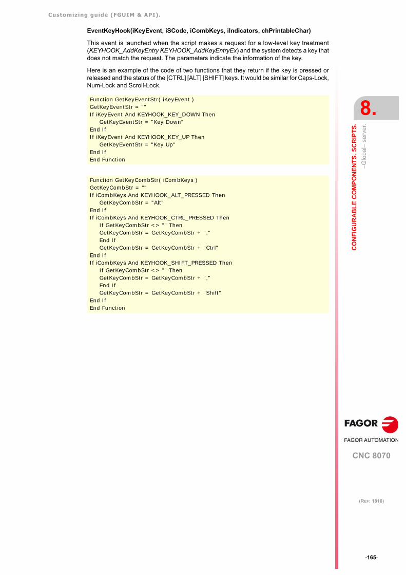
Customizing guide (FGUIM & API).
CNC 8070
CO
NF
IGU
RA
BL
E C
OM
PO
NE
NT
S. S
CR
IPT
S.
8.
–Glo
bal
– se
rver
.
·165·
(REF: 1810)
EventKeyHook(iKeyEvent, iSCode, iCombKeys, iIndicators, chPrintableChar)
This event is launched when the script makes a request for a low-level key treatment(KEYHOOK_AddKeyEntry KEYHOOK_AddKeyEntryEx) and the system detects a key thatdoes not match the request. The parameters indicate the information of the key.
Here is an example of the code of two functions that they return if the key is pressed orreleased and the status of the [CTRL] [ALT] [SHIFT] keys. It would be similar for Caps-Lock,Num-Lock and Scroll-Lock.
Function GetKeyEventStr( iKeyEvent )GetKeyEventStr = ""If iKeyEvent And KEYHOOK_KEY_DOWN Then
GetKeyEventStr = "Key Down"End IfIf iKeyEvent And KEYHOOK_KEY_UP Then
GetKeyEventStr = "Key Up"End IfEnd Function
Function GetKeyCombStr( iCombKeys )GetKeyCombStr = ""If iCombKeys And KEYHOOK_ALT_PRESSED Then
GetKeyCombStr = "Alt"End IfIf iCombKeys And KEYHOOK_CTRL_PRESSED Then
If GetKeyCombStr <> "" ThenGetKeyCombStr = GetKeyCombStr + ","End IfGetKeyCombStr = GetKeyCombStr + "Ctrl"
End IfIf iCombKeys And KEYHOOK_SHIFT_PRESSED Then
If GetKeyCombStr <> "" ThenGetKeyCombStr = GetKeyCombStr + ","End IfGetKeyCombStr = GetKeyCombStr + "Shift"
End IfEnd Function
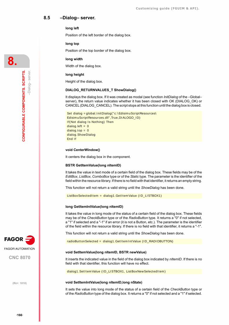
Customizing guide (FGUIM & API).
CNC 8070
8.
CO
NF
IGU
RA
BL
E C
OM
PO
NE
NT
S. S
CR
IPT
S.
–D
ialo
g– s
erve
r.
·166·
(REF: 1810)
8.5 –Dialog– server.
long left
Position of the left border of the dialog box.
long top
Position of the top border of the dialog box.
long width
Width of the dialog box.
long height
Height of the dialog box.
DIALOG_RETURNVALUES_T ShowDialog()
It displays the dialog box. If it was created as modal (see function InitDialog of the –Global–server), the return value indicates whether it has been closed with OK (DIALOG_OK) orCANCEL (DIALOG_CANCEL). The script stops at this function until the dialog box is closed.
void CenterWindow()
It centers the dialog box in the component.
BSTR GetItemValue(long nItemID)
It takes the value in text mode of a certain field of the dialog box. These fields may be of theEditBox, ListBox, ComboBox type or of the Static type. The parameter is the identifier of thefield within the resource library. If there is no field with that identifier, it returns an empty string.
This function will not return a valid string until the ShowDialog has been done.
long GetItemIntValue(long nItemID)
It takes the value in long mode of the status of a certain field of the dialog box. These fieldsmay be of the CheckButton type or of the RadioButton type. It returns a "0" if not selected,a "1" if selected and a "-1" if an error (it is not a Button, etc.). The parameter is the identifierof the field within the resource library. If there is no field with that identifier, it returns a "-1".
This function will not return a valid string until the ShowDialog has been done.
void SetItemValue(long nItemID, BSTR newValue)
It inserts the indicated value in the field of the dialog box indicated by nItemID. If there is nofield with that identifier, this function will have no effect.
void SetItemIntValue(long nItemID,long nState)
It sets the value into long mode of the status of a certain field of the CheckButton type orof the RadioButton type of the dialog box. It returns a "0" if not selected and a "1" if selected.
Set dialog =global.InitDialog("c:\EdisimuScriptResources\ EdisimuScriptResources.dll",True,DIALOGO_ID)If(Not dialog Is Nothing) Then dialog.left = 0dialog.top = 0dialog.ShowDialogEnd If
ListBoxSelectedItem = dialog1.GetItemValue (ID_LISTBOX1)
radioButtonSelected = dialog1.GetItemIntValue (ID_RADIOBUTTON)
dialog1.SetItemValue (ID_LISTBOX1, ListBoxNewSelectedItem)
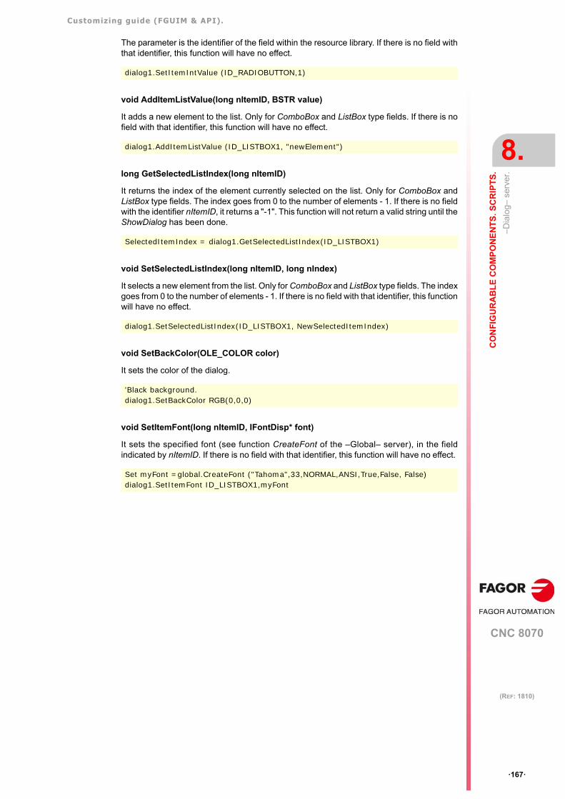
Customizing guide (FGUIM & API).
CNC 8070
CO
NF
IGU
RA
BL
E C
OM
PO
NE
NT
S. S
CR
IPT
S.
8.
–D
ialo
g– s
erve
r.
·167·
(REF: 1810)
The parameter is the identifier of the field within the resource library. If there is no field withthat identifier, this function will have no effect.
void AddItemListValue(long nItemID, BSTR value)
It adds a new element to the list. Only for ComboBox and ListBox type fields. If there is nofield with that identifier, this function will have no effect.
long GetSelectedListIndex(long nItemID)
It returns the index of the element currently selected on the list. Only for ComboBox andListBox type fields. The index goes from 0 to the number of elements - 1. If there is no fieldwith the identifier nItemID, it returns a "-1". This function will not return a valid string until theShowDialog has been done.
void SetSelectedListIndex(long nItemID, long nIndex)
It selects a new element from the list. Only for ComboBox and ListBox type fields. The indexgoes from 0 to the number of elements - 1. If there is no field with that identifier, this functionwill have no effect.
void SetBackColor(OLE_COLOR color)
It sets the color of the dialog.
void SetItemFont(long nItemID, IFontDisp* font)
It sets the specified font (see function CreateFont of the –Global– server), in the fieldindicated by nItemID. If there is no field with that identifier, this function will have no effect.
dialog1.SetItemIntValue (ID_RADIOBUTTON,1)
dialog1.AddItemListValue (ID_LISTBOX1, "newElement")
SelectedItemIndex = dialog1.GetSelectedListIndex(ID_LISTBOX1)
dialog1.SetSelectedListIndex(ID_LISTBOX1, NewSelectedItemIndex)
'Black background.dialog1.SetBackColor RGB(0,0,0)
Set myFont =global.CreateFont ("Tahoma",33,NORMAL,ANSI,True,False, False)dialog1.SetItemFont ID_LISTBOX1,myFont
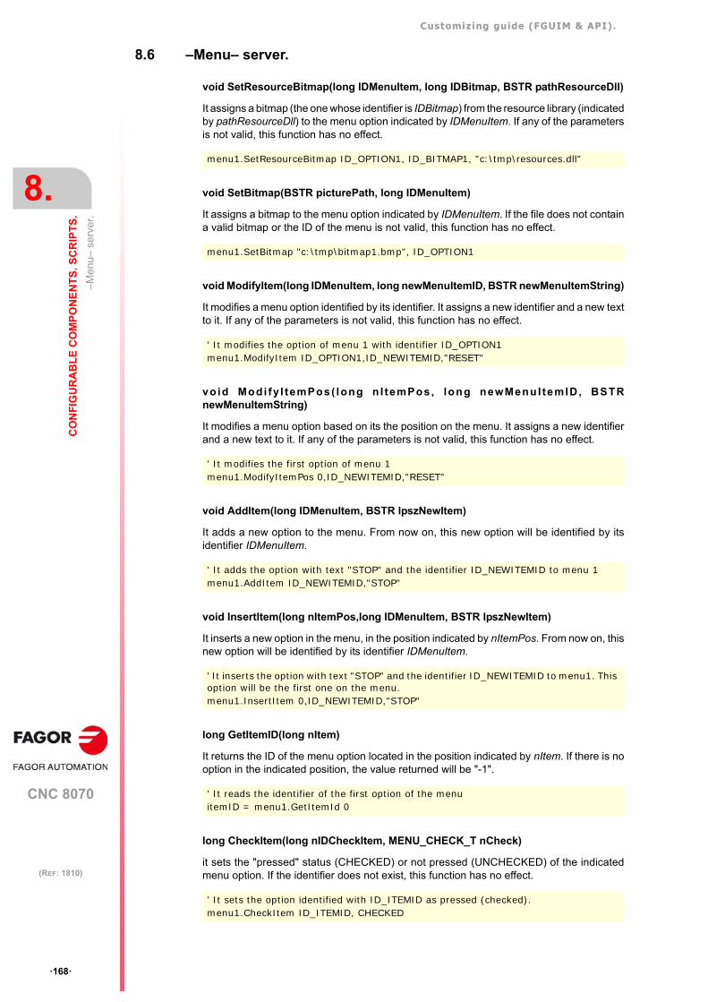
Customizing guide (FGUIM & API).
CNC 8070
8.
CO
NF
IGU
RA
BL
E C
OM
PO
NE
NT
S. S
CR
IPT
S.
–Me
nu–
serv
er.
·168·
(REF: 1810)
8.6 –Menu– server.
void SetResourceBitmap(long IDMenuItem, long IDBitmap, BSTR pathResourceDll)
It assigns a bitmap (the one whose identifier is IDBitmap) from the resource library (indicatedby pathResourceDll) to the menu option indicated by IDMenuItem. If any of the parametersis not valid, this function has no effect.
void SetBitmap(BSTR picturePath, long IDMenuItem)
It assigns a bitmap to the menu option indicated by IDMenuItem. If the file does not containa valid bitmap or the ID of the menu is not valid, this function has no effect.
void ModifyItem(long IDMenuItem, long newMenuItemID, BSTR newMenuItemString)
It modifies a menu option identified by its identifier. It assigns a new identifier and a new textto it. If any of the parameters is not valid, this function has no effect.
void Modi fy I temPos( long n I temPos, long newMenuI temID, BSTRnewMenuItemString)
It modifies a menu option based on its the position on the menu. It assigns a new identifierand a new text to it. If any of the parameters is not valid, this function has no effect.
void AddItem(long IDMenuItem, BSTR lpszNewItem)
It adds a new option to the menu. From now on, this new option will be identified by itsidentifier IDMenuItem.
void InsertItem(long nItemPos,long IDMenuItem, BSTR lpszNewItem)
It inserts a new option in the menu, in the position indicated by nItemPos. From now on, thisnew option will be identified by its identifier IDMenuItem.
long GetItemID(long nItem)
It returns the ID of the menu option located in the position indicated by nItem. If there is nooption in the indicated position, the value returned will be "-1".
long CheckItem(long nIDCheckItem, MENU_CHECK_T nCheck)
it sets the "pressed" status (CHECKED) or not pressed (UNCHECKED) of the indicatedmenu option. If the identifier does not exist, this function has no effect.
menu1.SetResourceBitmap ID_OPTION1, ID_BITMAP1, "c:\tmp\resources.dll"
menu1.SetBitmap "c:\tmp\bitmap1.bmp", ID_OPTION1
' It modifies the option of menu 1 with identifier ID_OPTION1menu1.ModifyItem ID_OPTION1,ID_NEWITEMID,"RESET"
' It modifies the first option of menu 1menu1.ModifyItemPos 0,ID_NEWITEMID,"RESET"
' It adds the option with text "STOP" and the identifier ID_NEWITEMID to menu 1menu1.AddItem ID_NEWITEMID,"STOP"
' It inserts the option with text "STOP" and the identifier ID_NEWITEMID to menu1. This option will be the first one on the menu.menu1.InsertItem 0,ID_NEWITEMID,"STOP"
' It reads the identifier of the first option of the menuitemID = menu1.GetItemId 0
' It sets the option identified with ID_ITEMID as pressed (checked). menu1.CheckItem ID_ITEMID, CHECKED
Customizing guide (FGUIM & API).
CNC 8070
CO
NF
IGU
RA
BL
E C
OM
PO
NE
NT
S. S
CR
IPT
S.
8.
–Me
nu–
serv
er.
·169·
(REF: 1810)
long EnableItem(long nIDEnableItem, MENU_ENABLE_TnEnable)
It sets the ENABLED status, DISABLED status or shaded (GRAYED) status of the indicatedmenu option. If the identifier does not exist, this function has no effect.
long DeleteItem(long nItemID)
It deletes the indicated menu option. If the identifier does not exist, this function has no effect.
boolean IsItemEnabled(long IDMenuItem)
It indicates whether the option is enabled or not. If the identifier is not valid, it returns FALSE.
boolean IsItemChecked(long IDMenuItem)
It indicates whether the option is pressed or not. If the identifier is not valid, it returns FALSE.
BSTR GetItemString(long IDMenuItem)
It returns the text of the indicated option. If the identifier is not valid, it returns an empty string.
long GetItemCount()
It returns the number of options of the menu.
long DeleteItemPos(long nItemPos)
It deletes the menu option located in the nItemPos position. The positions on the menu gofrom 0 to the number of options -1.
'It disables the option identified with ID_ITEMID.menu1.EnableItem ID_ITEMID, DISABLED
'It removes the option identified with ID_ITEMID from the menu.menu1.DeleteItem ID_ITEMID
'It checks whether the ID_ITEMID option is enabled or not.If(myMenu.IsItemEnabled(ID_ITEMID)) Then msgbox "Enabled"
'It checks whether the ID_ITEMID option is pressed or not.If(myMenu.IsItemChecked(ID_ITEMID)) Then msgbox "Checked"
' It reads and displays on the screen the text of the option ID_ITEMID msgbox myMenu.GetItemString(ID_ITEMID)
' It removes the first option of the menu.menu1.DeleteItemPos 0
Customizing guide (FGUIM & API).
CNC 8070
8.
CO
NF
IGU
RA
BL
E C
OM
PO
NE
NT
S. S
CR
IPT
S.
Cre
atin
g a
reso
urc
e li
brar
y.
·170·
(REF: 1810)
8.7 Creating a resource library.
Until now we've seen that it is possible to create menus, bitmaps, dialogs, etc. using aresource library (dll). We'll now see how to create these libraries and how to insert theresources in them so you can use them from the script later on.
A VC++ editor will be used to create a resource library. For example, we will create a resourcelibrary called: EdisimuScriptResources.
1 Create a new "MFC AppWizard (dll)" type project (File -> New -> Project) with the desiredname. In our case, EdisimuScriptResources. Select the "Automation" option and leavethe other options that VC++ offers by default.
2 Once the project has been created, use the resource editor of the VC++ to insert all thenecessary resources (strings, dialogs, icons, menus, etc). Each one of these resourcesmust be assigned a significant identifier (ID property of the resource) in order to be ableto use it later on.
3 For these resources to be recognized from the FGUIM, their identifiers must be insertedin the TypeLibrary (tlb) of the library that is being created. To do this, open the fileresource.h and find the identifiers (defines) of the resources that have been inserted. Foreach identifier, add an enumerated value in the "odl" file of the project. These enumeratedvalues will be those used in the script to identify the resources of the library.
4 The library (dll) and the TypeLibrary (tlb) must be registered in order to be able to accessthese identifiers from the script. To register a TypeLibrary and the library (dll) at the sametime, enter the following instruction in the InitInstance function of the DLL.
The iden t i f i e r LIB ID_Ed is imuScr ip tResources i s de f ined in the f i l eEdisimuScriptResources_i.h (file generated by the odl, see next paragraph). To be ableto use it, include the following lines in the cpp file:
To use the function AfxOleRegisterTypeLib, include the following line:
5 The following data must be defined in the "MIDL" folder of the odl settings: To do that,select the odl file and press "Project -> Settings".
In the "Output File Name", the name of the TypeLibrary that will be generated whencompiling the odl (EdisimuScriptResources.tlb).
In the "Output header file name", the name of the file.h file to be generated(EdisimuScriptResources_i.h) must be defined.
resource.h...#define ID_TEJEC_SIMU 12779#define ID_SKIP_BLOCK 12780...
Projectname.odl#include "resource.h"...library ProjectName{importlib("stdole32.tlb");typedef enum Resources_st {TEJEC_ID = ID_TEJEC_SIMU,SKIPBLOCK_ID = ID_SKIP_BLOCK,} Resources_t;...
AfxOleRegisterTypeLib(AfxGetInstanceHandle(),LIBID_EdisimuScriptResources, _T("EdisimuScriptResources.TLB"));
#include <initguid.h>#include "EdisimuScriptResources_i.h"
#include "AfxCtl.h"
Customizing guide (FGUIM & API).
CNC 8070
CO
NF
IGU
RA
BL
E C
OM
PO
NE
NT
S. S
CR
IPT
S.
8.
Cre
atin
g a
reso
urc
e li
brar
y.
·171·
(REF: 1810)
6 Finally, the DLL must be registered. To do that, use the Windows program regsvr32.exe.
After this, just enter the tlb file in the script using the "Add File" option of the "Files" menu.Once this is done, select it from the "Components" list. The "Types" lists will show thename of the enumerated (Resources_t) and the "Fields" list will show the identifiers ofthe library resources (TEJEC_ID, SKIPBLOCK_ID, etc.). These identifiers may be usedin the different functions that admit them (menu.Checkitem, etc.).
Regsvr32.exe c:\ cnc8070\ mtb\ mmc\ config\ BinaryData\ EdisimuScript\ EdisimuScriptResource.dll

Customizing guide (FGUIM & API).
CNC 8070
8.
CO
NF
IGU
RA
BL
E C
OM
PO
NE
NT
S. S
CR
IPT
S.
Cre
atin
g a
reso
urc
e li
brar
y.
·172·
(REF: 1810)
CNC 8070
9
·173·
(REF: 1810)
9. API8070.
The API8070 is a library for the development of applications that will communicate with theCNC. This library offers a number of objects (COM) that in turn export some functions whichare the ones that actually communicate with the kernel of the CNC. Since the library has beencreated with COM objects, several applications may be connected to the CNC through it atthe same time. Likewise, since the connection to the CNC is a COM connection, theapplication do not have to be at the same PC as this one (they may be remote applications).
The CNC is also an OPC server and all its variables may be accessed via OPC by anyapplication (interface) that is connected to the CNC usin the API8070. To turn the CNC intoan OPC server, i t must be f i rs t reg is tered as such. See "9 .2 .21 Server–Cnc8070.OpcServer–" on page 228.
Example of how to register using a "reg" type file:
REGEDITHKEY_CLASSES_ROOT\CLSID\{4210FF60-D373-11ce-B4B5-C46F03C10000} = CNC8070 OPC ServerHKEY_CLASSES_ROOT\CLSID\{4210FF60-D373-11ce-B4B5-C46F03C10000}\ProgID = CNC8070HKEY_CLASSES_ROOT\CLSID\{4210FF60-D373-11ce-B4B5-C46F03C10000}\LocalServer32 = c:\users\myApplication.exeHKEY_CLASSES_ROOT\CNC8070 = CNC8070 OPC ServerHKEY_CLASSES_ROOT\CNC8070\CLSID = {4210FF60-D373-11ce-B4B5-C46F03C10000}HKEY_CLASSES_ROOT\CNC8070\OPC
Customizing guide (FGUIM & API).
CNC 8070
9.
AP
I80
70.
Ste
ps to
follo
w to
use
the
AP
I80
70.
·174·
(REF: 1810)
9.1 Steps to follow to use the API8070.
1 The API8070 has been implemented in a dll (Api8070.dll) that is located in the samedirectory as the other executable files of the CNC (..\Fagor\Release\). Since this libraryis a COM object server, it must be registered before it can be used. This operation is donemanually using the Windows program: regsvr32.exe (if the CNC is installed, theapi8070.dll is already installed).
2 To connect a remote application to the CNC, besides registering the Api8070.dll at thePC of the CNC, Windows must be "told" where to look for the object server. To do this,first register the API8070.dll at the remote PC and then use the Windows tool"dcomcnfg.exe" (distributed COM configurator or DCOM) to set the PC of the CNC asa server.
3 Once the library has been registered, to be able to use its services, first the server objectsmust be created. There are different servers depending on the type of service. Thus,there is the "cnc8070.variables" server to access the CNC variables, the"cnc8070.MachineParameters" server to access the machine parameters and so forth.The servers are created differently in each programming language. Whereas in VB it isonly required to declare a server type variable and connect it through a Set, in VC itrequires "QueryInterface", "CoCreateInstance" or "OleRun" type functions (for furtherinformation, refer to the documentation from Microsoft).
4 To be able to access the types, servers and functions of the API8070 during compilation,in VC the api8070_i.h file must be included in the project. In VB, simply add a referenceto the library of types of the API (Api8070.tlb). These steps are not necessary becauseit may be linked with the COM objects while in execution, but they are recommendedbecause they make programming easier.
5 All the services may be used once the server objects have been created, In VC, whendone with them, they will have to be destroyed using the Release function.
Control XPRemoteConnections. Remote connection from anapplication to the CNC.
Windows 95.
On W95, the remote connection to the kernel server of the CNC (once it has been launched)may be done from a VB application using the instruction Set kernel.
Setkernel = CNC8070.kernel
Windows 2000 and XP.
On W2000 and Xp, the remote connection to the CNC from an application cannot be donedirectly. In these cases, the remote connection is done using the method CreateObjectExof the control ocx XPRemoteConnections.
Set kernel = myOcx.CreateObjectEx ("cnc8070.kernel", "", 1).
The non-remote connections (when the CNC has not been launched), are still done the sameway as on W95.
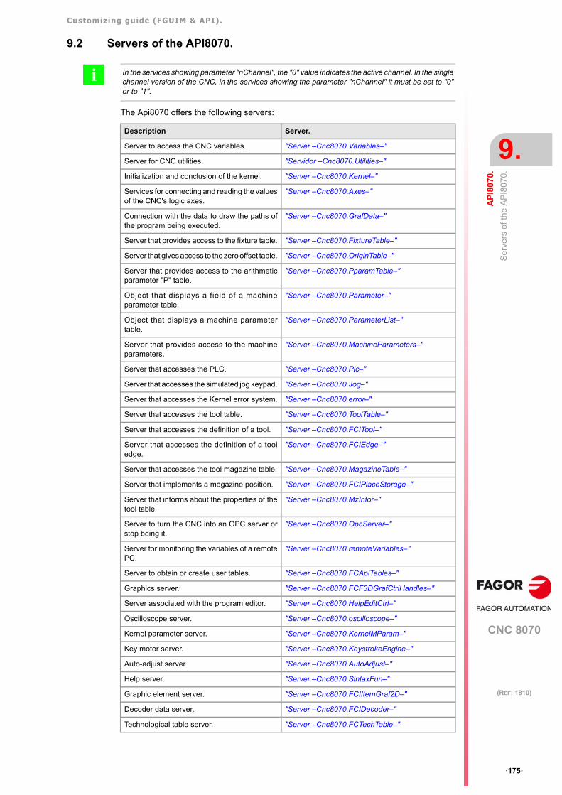
Customizing guide (FGUIM & API).
CNC 8070
AP
I80
70.
9.
Se
rve
rs o
f th
e A
PI8
070
.
·175·
(REF: 1810)
9.2 Servers of the API8070.
The Api8070 offers the following servers:
In the services showing parameter "nChannel", the "0" value indicates the active channel. In the singlechannel version of the CNC, in the services showing the parameter "nChannel" it must be set to "0"or to "1".
i
Description Server.
Server to access the CNC variables. "Server –Cnc8070.Variables–"
Server for CNC utilities. "Servidor –Cnc8070.Utilities–"
Initialization and conclusion of the kernel. "Server –Cnc8070.Kernel–"
Services for connecting and reading the valuesof the CNC's logic axes.
"Server –Cnc8070.Axes–"
Connection with the data to draw the paths ofthe program being executed.
"Server –Cnc8070.GrafData–"
Server that provides access to the fixture table. "Server –Cnc8070.FixtureTable–"
Server that gives access to the zero offset table. "Server –Cnc8070.OriginTable–"
Server that provides access to the arithmeticparameter "P" table.
"Server –Cnc8070.PparamTable–"
Object that displays a field of a machineparameter table.
"Server –Cnc8070.Parameter–"
Object that displays a machine parametertable.
"Server –Cnc8070.ParameterList–"
Server that provides access to the machineparameters.
"Server –Cnc8070.MachineParameters–"
Server that accesses the PLC. "Server –Cnc8070.Plc–"
Server that accesses the simulated jog keypad. "Server –Cnc8070.Jog–"
Server that accesses the Kernel error system. "Server –Cnc8070.error–"
Server that accesses the tool table. "Server –Cnc8070.ToolTable–"
Server that accesses the definition of a tool. "Server –Cnc8070.FCITool–"
Server that accesses the definition of a tooledge.
"Server –Cnc8070.FCIEdge–"
Server that accesses the tool magazine table. "Server –Cnc8070.MagazineTable–"
Server that implements a magazine position. "Server –Cnc8070.FCIPlaceStorage–"
Server that informs about the properties of thetool table.
"Server –Cnc8070.MzInfor–"
Server to turn the CNC into an OPC server orstop being it.
"Server –Cnc8070.OpcServer–"
Server for monitoring the variables of a remotePC.
"Server –Cnc8070.remoteVariables–"
Server to obtain or create user tables. "Server –Cnc8070.FCApiTables–"
Graphics server. "Server –Cnc8070.FCF3DGrafCtrlHandles–"
Server associated with the program editor. "Server –Cnc8070.HelpEditCtrl–"
Oscilloscope server. "Server –Cnc8070.oscilloscope–"
Kernel parameter server. "Server –Cnc8070.KernelMParam–"
Key motor server. "Server –Cnc8070.KeystrokeEngine–"
Auto-adjust server "Server –Cnc8070.AutoAdjust–"
Help server. "Server –Cnc8070.SintaxFun–"
Graphic element server. "Server –Cnc8070.FCIItemGraf2D–"
Decoder data server. "Server –Cnc8070.FCIDecoder–"
Technological table server. "Server –Cnc8070.FCTechTable–"
Customizing guide (FGUIM & API).
CNC 8070
9.
AP
I80
70.
Se
rve
rs o
f th
e A
PI8
070
.
·176·
(REF: 1810)
9.2.1 Server –Cnc8070.Variables–
Server to access the CNC variables.
Services of the server.
HVAR OpenVariable(BSTR namevar)
It creates the connection to the variables indicated by namevar (Ej; "A.ATIPPOS.1"), andreturns a variable identifier that may be used in following services. If the value returned bythe function is equal to INVALID_HVAR, it is possible that there was an error, so it shouldbe verified using the GetLastError function.
void CloseVariable(HVAR h_var)
It closes the connection to the variable indicated by h_var. The h_var identifier will not bevalid once this function has been called upon. This function must be called upon, for eachconnected variable, before closing the application.
BSTR ReadTxt(HVAR h_var, [in, optional, defaultvalue(-1)] long size)
It reads the value of the h_var variable and it returns it in text form. The optional parameteris the size of the text to be read; if left at its default value (-1), it will be read entirely. Whenreturning the text "????", it may be due to an error, therefore, it should be tested using theGetLastError function.
API_RETVALUES_T OpenReport(HVAR h_var)
It indicates that it must warn every time the value of the h_var variable changes. For a variableto stop warning, the report must be closed (CloseReport).
Only certain variables warn the application connected to them every time they change (reportvariables). The client of the variable must implement the function to be warned. See"9.3 Notifications of the servers." on page 263.
boolean HandleReport(HVAR h_var, long param1, VARIANT param2)
Using this function only makes sense when implementing the function to warn of variablechange. It is used to ask each variable with connected report whether the report belongs toit or not.
If the function return TRUE, it means that the variable causing the warning was h_var. Fromthis instant on, its value may be read using one of its read functions.
In order for the reader functions of report variables (ReadInt, ReadDouble, etc) to give theupdated value after a warning is sent out, a HandleReport of that variable must be made first.
void GeneraReport(HVAR h_var)
It orders the indicated variable to sent a report.
API_RETVALUES_T CloseReport(HVAR h_var)
It closes the report of the indicated variable.
boolean IsReport(HVAR h_var)
It indicates whether the variable is a report variable (it warns when it changes) or not
boolean IsReportOpened(HVAR h_var)
It indicates whether there is an open report for the h_var variable or not.
long GetNIntegers(HVAR h_var)
It informs of the number of integers that the value returned by the ReadTxt function will have.
void SetNIntegers(HVAR h_var, long nIntegers)
It sets of the number of integers that the value returned by the ReadTxt function will have.
Customizing guide (FGUIM & API).
CNC 8070
AP
I80
70.
9.
Se
rve
rs o
f th
e A
PI8
070
.
·177·
(REF: 1810)
long GetNDecimals(HVAR h_var)
It informs of the number of decimals that the value returned by the ReadTxt function will have.
void SetNDecimals(HVAR h_var, long nDecimals)
It sets of the number of decimals that the value returned by the ReadTxt function will have.
boolean GetPad(HVAR h_var)
It informs whether the value returned by the ReadTxt function will have filling zeros or notuntil the desired number of integers is reached.
void SetPad(HVAR h_var, boolean bPad)
It defines whether the value returned by the ReadTxt function will have filling zeros or notuntil the desired number of integers is reached.
boolean IsWritable(HVAR h_var)
It indicates whether the variable may be written or not.
boolean IsValid(HVAR h_var)
It indicates whether the h_var identifier is valid or not.
API_RETVALUES_T WriteTxt(HVAR h_var, BSTR text)
It writes in the variable the value indicated by the text parameter (the value in text mode)The variable must be a write variable.
HVAR SetName(HVAR h_var, BSTR namevar)
It connects the h_var identifier to the variable indicated by namevar. This function is similarto OpenVariable, although SetName can be used to connect to several variables by usingthe same identifier and without having to close them later. If the value returned by the functionis equal to INVALID_HVAR, it is possible that there was an error, so it should be verified usingthe GetLastError function.
long ReadInt(HVAR h_var, [in, defaultvalue(NO_HVAR_INDEX)] int index1, [in,defaultvalue(NO_HVAR_INDEX)] int index2)
It reads the value of h_var and it returns it in integer mode. If index1 or index1 and index2havea value different from that of NO_HVAR_INDEX, it means that the variable to be read is anarray type (otherwise, it will not be read correctly). In this case, it reads the element of thearray indicated with both indexes.
When returning the API_RET_ERROR value, it may be due to an error, therefore, it shouldbe tested using the GetLastError function.
API_RETVALUES_T Wr i te Int (HVAR h_var, long newval , [ in ,defaultvalue(NO_HVAR_INDEX)] long index1, [in, defaultvalue(NO_HVAR_INDEX)]long index2)
It writes the value newval in the variable (it must be a write variable). If it is an array variable,use parameters index1 and index2 to identify to the element of the array.
double ReadDouble(HVAR h_var, [in, defaultvalue(NO_HVAR_INDEX)] long index1,[in, defaultvalue(NO_HVAR_INDEX)] long index2);
It reads the value of h_var and it returns it in double mode. The result is returned in parameterresul. If it is an array variable, use parameters index1 and index2 to identify to the elementof the array.
When returning the API_RET_ERROR value, it may be due to an error, therefore, it shouldbe tested using the GetLastError function.
Before connecting h_var to a variable for the first time using SetName, initialize it to INVALID_HVAR(-1); any other positive value is a valid "handle" value and the function will reconnect that handle toanother variable
i
Customizing guide (FGUIM & API).
CNC 8070
9.
AP
I80
70.
Se
rve
rs o
f th
e A
PI8
070
.
·178·
(REF: 1810)
API_RETVALUES_T WriteDouble(HVAR h_var, double newval, long index1, longindex2)
It writes the value newval in the variable (it must be a write variable). If it is an array variable,use parameters index1 and index2 to identify to the element of the array.
LPVARIANT ReadBin(HVAR h_var, long size)
It reads a variable and returns its value in binary array format. It is usually used to read binarytype variables. For example, the G.HGS variable depending on which of its bits are activatedand which deactivated, indicates which "G" functions are active at the CNC.
When returning the API_RET_ERROR value, it may be due to an error, therefore, it shouldbe tested using the GetLastError function.
API_RETVALUES_T WriteBin(HVAR h_var, LPVARIANT pOrig, long size)
It writes a binary variable.
BSTR ReadTxtArray(HVAR* pH_vars, short numH_vars)
It reads the values of a number of variables and returns them in a string separated bycommas.
If any of the returned values is "????", it may be due to an error, therefore, it should be testedusing the GetLastError function.
void SetHexView(HVAR h_var, boolean bHexView)
It indicates whether the value returned by ReadTxt is in hexadecimal format or not.
long ReadIntArray(VARIANT* idArray, VARIANT* valuesArray)
In order to minimize the remote PC accessing time, it reads by batches (blocks); in otherwords, it passes an array with the "handles" obtained when opening variables using theprevious method. This obtains an array of values from reading those variables. The type ofthe variables must be "int". API_RET_ERROR is returned if there is a problem orAPI_RET_OK if the reading was successful.
long WriteIntArray(VARIANT* idArray, VARIANT* valuesArray)
Same as the previous method for "int" type variables; but now it passes an array with valuesto be written into those variables. An API_RET_OK is returned if the writing was successful.API_RET_ERROR if there is a problem.
long ReadDoubleArray(VARIANT* idArray, VARIANT* valuesArray)
Same as the "int" type reading, but for "double" type readings.
long WriteDoubleArray(VARIANT* idArray, VARIANT* valuesArray)
Same as the "int" type writing, but for "double" type writing.
BSTR GetLastError()
It returns a text describing the last error that occurred when using one of the previousfunctions. If the last call function has not caused an error, it returns "".
long GetStatusByte(long lFullStatus)
Retrieves the status byte of the FULLSTATUS variable.
long GetSubstatusByte(long lFullStatus)
Retrieves the substatus byte of the variable FULLSTATUS.
long ReadIntArray(VARIANT FAR* idArray, VARIANT FAR* valueArray)
Reads a group of variables in integer mode. The idArray parameter will be an array of integerswith the "handles" of the readable variables; it has to be an array VARIANT and the elementsof the array, in turn, are an integer VARIANT. The valueArray parameter will be an array ofintegers containing read information; it has to be an ARRAY VARIANT and the elements,in turn, are an integer VARIANT.
Customizing guide (FGUIM & API).
CNC 8070
AP
I80
70.
9.
Se
rve
rs o
f th
e A
PI8
070
.
·179·
(REF: 1810)
It returns API_RET_ERROR if something went wrong and API_RET_OK if everything wentwell.
long WriteIntArray(VARIANT FAR* idArray, VARIANT FAR* valueArray)
Writing a group of variables in integer mode. The idArray parameter will be an array ofintegers with the "handles" of the readable variables; it has to be an array VARIANT and theelements of the array, in turn, are an integer VARIANT. The valueArray parameter will be anarray of integers containing read information; it has to be an ARRAY VARIANT and theelements, in turn, are an integer VARIANT.
It returns API_RET_ERROR if something went wrong and API_RET_OK if everything wentwell.
long ReadDoubleArray(VARIANT FAR* idArray, VARIANT FAR* valueArray)
Read a group of "double" mode variables. The idArray parameter will be an array of integerswith the "handles" of the readable variables; it has to be an array VARIANT and the elementsof the array, in turn, are an integer VARIANT. The valueArray parameter will be an array ofintegers containing read information; it has to be an ARRAY VARIANT and the elements,in turn, are an double VARIANT.
It returns API_RET_ERROR if something went wrong and API_RET_OK if everything wentwell.
long WriteDoubleArray(VARIANT FAR* idArray, VARIANT FAR* valueArray)
Writing a group of variables in "double" mode. The idArray parameter will be an array ofintegers with the "handles" of the readable variables; it has to be an array VARIANT and theelements of the array, in turn, are an integer VARIANT. The valueArray parameter will be anarray of integers containing read information; it has to be an ARRAY VARIANT and theelements, in turn, are an double VARIANT.
It returns API_RET_ERROR if something went wrong and API_RET_OK if everything wentwell.
void DesconectarVariables()
Disconnect all connected variables (does not remove the FCVarDatos structure from the listin order to reconnect the variables, if required).
VARIABLETYPE_T GetVariableType(HVAR h_var)
Indicate the type (binary, string, double, etc.) of the indicated variable. The possible valuesof VARIABLETYPE_T are BYTETYPE, WORDTYPE, DWORDTYPE, FLOATTYPE,DOUBLETYPE, STRINGTYPE and BINARYTYPE.
VARIANT ReadVar(long h_var, long index1, long index2)
Reads the value of h_var and returns it in VARIANT mode. If it is an array variable, useparameters index1 and index2 to identify to the element of the array.
long WriteVar(long h_var, VARIANT newval, long index1, long index2)
Write the newval value in the variable h_var. If it is an array variable, use parameters index1and index2 to identify to the element of the array.
It returns API_RET_ERROR if something went wrong and API_RET_OK if everything wentwell.
long ReadVarArray(VARIANT FAR* idArray, VARIANT FAR* valueArray)
Reads a group of variables in VARIANT mode. The idArray parameter will be an array ofintegers with the "handles" of the readable variables; it has to be an array VARIANT and theelements of the array, in turn, are an integer VARIANT. The valueArray parameter will be anarray of integers containing read information; it constructs an ARRAY VARIANT.
It returns API_RET_ERROR if something went wrong and API_RET_OK if everything wentwell.
long WriteVarArray(VARIANT FAR* idArray, VARIANT FAR* valueArray)
Writing a group of variables in VARIANT mode. The idArray parameter will be an array ofintegers with the "handles" of the readable variables; it has to be an array VARIANT and the
Customizing guide (FGUIM & API).
CNC 8070
9.
AP
I80
70.
Se
rve
rs o
f th
e A
PI8
070
.
·180·
(REF: 1810)
elements of the array, in turn, are an integer VARIANT. The valueArray parameter will be anarray of integers containing read information; it constructs an ARRAY VARIANT.
It returns API_RET_ERROR if something went wrong and API_RET_OK if everything wentwell.
BOOL AplicarTransfInches(long h_var)
Indicates whether the variable h_var is affected by the change to millimeters/inches.
long ForceWriteInt(long h_var, long newval, long index1, long index2)
Writes a new value newval in the variable. With this function, the variable is always writtenregardless of its write permission. If it is an array variable, use parameters index1 and index2to identify to the element of the array.
It returns API_RET_ERROR if something went wrong and API_RET_OK if everything wentwell.
long GetFilterDelay(long h_var)
Retrieves the filter delay value.
void SetFilterDelay(long h_var, long delay)
Applies a filter with a delay value.
BOOL AplicarTransfInchesEx(long h_var)
Indicates whether the variable passed as a parameter is affected by the change tomillimeters/inches.
BOOL IsReportOpened2(long h_var, LPDISPATCH pSink)
It indicates whether there is an open report for the h_var variable or not.
long BroadcastReport(long h_var)
Send a report to all customers of a variable. It returns 0 if it went well.
long ReadNDoubleArray(HVAR h_var, VARIANT* valuesArray, long size)
Function to read an array of doubles. This type of variable access allows all the coordinatesof a point to be read simultaneously. It returns the number of copied array elements; if thereis an error, it returns a negative number.
Return values (API_RETVALUES_T)
API_RET_ERROR
An error has occurred during the operation. The GetLastError function may be used to knowwhat the error is.
API_RET_OK
Everything is OK.
Customizing guide (FGUIM & API).
CNC 8070
AP
I80
70.
9.
Se
rve
rs o
f th
e A
PI8
070
.
·181·
(REF: 1810)
9.2.2 Servidor –Cnc8070.Utilities–
Server for CNC utilities.
Services of the server.
BSTR Get8070PathRemote(PATH8070_T path8070)
It returns a particular CNC path depending on parameter path8070. This function is usedwhen the CNC is in PC other than the application that is using it.
Values of the enumerated (group) PATH8070_T:
BSTR Get8070Path(PATH8070_T path8070)
It returns a particular CNC path depending on parameter path8070.
boolean IsVisualizationInInches(long nChannel, CNC_MODE_T mode)
It returns the type of display (TRUE = inches, FALSE = millimeters) in the indicated mode(SIMULATION_MODE, EJECUTION_MODE). This mode needs not be the same as that ofthe kernel. In other words, the kernel can be in inches, while the visualization can bepresented in millimeters. The values read (variables, coordinates, etc) using the servers willbe in the display mode. The parameter nChannel will take the values from 0 toCHANNAL_MAX-1.
void PutVisualizationInInches(long nChannel, CNC_MODE_T mode, booleanbModeInches)
Add the type of display (TRUE = inches, FALSE = millimeters) in the indicated mode(SIMULATION_MODE, EJECUTION_MODE). The parameter nChannel will take the valuesfrom 0 to CHANNAL_MAX-1.
BOOL AreNewGraphicsActive()
Indicates whether HD graphics performance is active.
MAINPATH Main path.("\\Computer1\Cnc8070")
BINPATH Path of executable files.("\\Computer1\Cnc8070\Fagor\Release")
CONFIGPATH Path of -ini- files.("\\Computer1\Cnc8070\MTB\Config")
IMAGESPATH Path of bitmap files.("\\Computer1\Cnc8070\Fagor\Images")
LANGPATH Path of language files.("\\Computer1\Cnc8070\Fagor\Lang")
DATAPATH Path of data files.("\\Computer1\Cnc8070\MTB\Data")
PLCPATH Path of the PLC.("\\Computer1\Cnc8070\MTB\PLC")
PRGPATH Path of the programs.("\\Computer1\Cnc8070\Users\prg")
PROFILEPATH Path of the profiles.("\\Computer1\Cnc8070\Users\Profile")
POCKETPATH Path of the pockets.("\\Computer1\Cnc8070\Users\Pocket")
TMPPATH Path of temporary data.("\\Computer1\Cnc8070\Tmp")
DRIVEPATH Path of the drivers.("\\Computer1\Cnc8070\MTB\Drive")
OEMSUBPATH Path of the OEM.("\\Computer1\Cnc8070\MTB\Sub")
REPORTSPATH Path of the reports.("\\Computer1\Cnc8070\Users\Reports")
Customizing guide (FGUIM & API).
CNC 8070
9.
AP
I80
70.
Se
rve
rs o
f th
e A
PI8
070
.
·182·
(REF: 1810)
BSTR Get8070Language()
Retrieves the language of the CNC.
void WriteTxtInBlackBox(LPCTSTR pTxt, long nSimul)
Writes the text specified in the Black Box text file and also in the encoded file. The parameterpTxt contains the write text and nSimul indicates whether you want to write to the execution(MODE_EXEC_REAL) or simulation (MODE_SIMULATION) file.
long error_to_txt(long codigoBuscado, BSTR FAR* infoText, BSTR FAR* infoFile,BOOL FAR* infobPopup)
Searches for an error code and returns a description text and a help file, and whether thehelp file is to be displayed automatically when skipping the error. The parameters are:
BOOL CustomPassword_IsValid(BSTR szName)
Checks if there is a password or not; file ..\Users\Session\MMC\Config\fcp.epl (passwordencrypted file).
BOOL CustomPassword_Set(BSTR szName, BSTR szOldPassword, BSTRszNewPassword)
Assigning a new password.
BOOL CustomPassword_Check(BSTR szName, BSTR szPassword)
Checks if the password is valid.
codigoBuscado Error code.
infoText Parameter where the text is left with the information corresponding tothe error.
infoFile Parameter where the name of the file with the error information is left.
infobPopup Parameter where it indicates if it is popup or not.
szName User name.
szName User name.
szOldPassword Current password.
szNewPassword New password
szName User name.
szPassword Password to check.
Customizing guide (FGUIM & API).
CNC 8070
AP
I80
70.
9.
Se
rve
rs o
f th
e A
PI8
070
.
·183·
(REF: 1810)
9.2.3 Server –Cnc8070.Kernel–
Initialization and conclusion of the kernel.
Services of the server.
API_RETVALUES_T InitKernel(BSTR sStartMode)
Function to initialize and start up the Kernel. This is a high level function that involves a longprocess that will send notifications about the progress of the initialization. ParametersStartMode indicates how the Kernel is used.
When returning the API_RET_INVALID_HVAR value, it may be due to an error, therefore,it should be tested using the GetLastError function.
API_RETVALUES_T CloseKernel()
Function to end the Kernel.
boolean KernelExist()
Function informing of the existence and correct initialization of the real Kernel.
boolean KernelExistSim()
Function informing of the existence and correct initialization of the simulation Kernel.
## Program selection ##
SelectProgram(long nChannel, BSTR sProg)
It selects a program in the indicated channel to be executed.
SelectProgramSim(long nChannel, BSTR sProg)
It selects a program in the indicated channel to be simulated.
## Simulation conditions ##
API_RETVALUES_T SkipBlock(long nChannel, BOOL bActivate)
It activates or cancels block skip in simulation for the indicated channel.
API_RETVALUES_T SimulateM01 (long nChannel, BOOL bActivate)
It activates or cancels function M01 in simulation for the indicated channel.
API_RETVALUES_T SWLimitsON(long nChannel, BOOL bActivate)
It activates or cancels the software limits in simulation for the indicated channel.
If the client of the Kernel wants to receive notifications, it would have to implement a function to doso. See "9.3 Notifications of the servers." on page 263..i
K simulated Kernel (for PC's).
X Real time Kernel (for controls).
K+ Simulated Kernel + simulation Kernel (for program simulation, see the Edisimucomponent of the CNC).
X+ Real time Kernel + simulation Kernel.
Customizing guide (FGUIM & API).
CNC 8070
9.
AP
I80
70.
Se
rve
rs o
f th
e A
PI8
070
.
·184·
(REF: 1810)
## Work mode ##
long SetMode(long nChannel, long mode)
It sets the indicated mode in the kernel and in the interface. The values that can be set are:NOT_MANUAL_MODE and MANUAL_MODE. It also activates or cancels the PLC marks"MANUAL" and "AUTOMAT". These marks are necessary to restore the kernel mode aftera KernelReset.
If nChannel is set to "-1" or parameter samemode is TRUE, it will try to change the modeof all the channels. This function returns the number of channels that have switched to theindicated mode or API_RET_ERROR if something went wrong.
The channels that are in execution will not change modes. Also, if the execution in a channelis interrupted, it will reset.
## Stop program execution ##
API_RETVALUES_T SetFeedhold(long nChannel)
(Only valid from the CYStart report of the PLC).
API_RETVALUES_T ClearFeedhold(long nChannel)
(Only valid from the CYStart report of the PLC).
API_RETVALUES_T SetFeedholdSim(long nChannel)
Functions to activate the FeedHold input in the indicated channel both in the real and thesimulation kernels.
API_RETVALUES_T ClearFeedholdSim(long nChannel)
Functions to deactivate the FeedHold input in the indicated channel both in the real and thesimulation kernels.
## Reset program execution ##
API_RETVALUES_T KernelReset(long nChannel)
Function to reset the real Kernel in the indicated channel.
API_RETVALUES_T KernelResetSim(long nChannel)
Function to reset the simulation Kernel in the indicated channel.
## Block execution ##
API_RETVALUES_T ExecBlock(long nChannel, BSTR sBlock)
It executes the sBlock block in the indicated channel.
(Only valid from the CYStart report of the PLC).
API_RETVALUES_T ExecBlockEx(long nChannel, BSTR sBlock)
Function that executes a series of blocks as if they were a single one. The blocks must beseparated from each other by CR, LF or both at the same time.
It creates a temporary file that contains a subroutine with these blocks and it calls uponExecBlock() with a subroutine calling block.
## Coordinate preset ##
API_RETVALUES_T PreSelection (BSTR str_axis, double value)
Preset the str_axis axis with the value value.
Customizing guide (FGUIM & API).
CNC 8070
AP
I80
70.
9.
Se
rve
rs o
f th
e A
PI8
070
.
·185·
(REF: 1810)
## Home search ##
API_RETVALUES_T ZeroSearch (BSTR str_axis)
Home search on the indicated axis. This function cancels the active zero offsets for this axis.
## Program execution ##
API_RETVALUES_T StartProgram(long nChannel)
It executes the program selected for execution in the indicated channel.
(Only valid from the CYStart report of the PLC).
API_RETVALUES_T StartProgramSim(long nChannel, SIMULATION_OPTIONS_Toptions)
It simulates the program selected for simulation in the indicated channel. Parameter optionsmay be either NO_OPT to simulate without options or NO_WRK to simulate without toolradius compensation.
API_RETVALUES_T ExecProgram(long nChannel, BSTR sprog)
It executes the indicated program.
(Only valid from the CYSTART report of the PLC).
API_RETVALUES_T ExecProgramSim( long nChannel , BSTR sprog,SIMULATION_OPTIONS_T options)
It simulates the indicated program. Parameter options has the same functionality as infunction StartProgramSim.
API_RETVALUES_T NextSingleStep(long nChannel)
It executes the next block of the program selected for execution in the indicated channel.The channel has to be in single block mode ((variable "[ch].G.SBLOCK" to 1).
(Only valid from the CYSTART report of the PLC).
API_RETVALUES_T NextSingleStepSim(long nChannel)
It simulates the next block of the program selected for simulation in the indicated channel.The channel has to be in single block mode ((variable "[ch].S.G.SBLOCK" to 1).
API_RETVALUES_T StartProgramSintaxCheck(long nChannel)
Start the syntactic check for the selected program. It first checks that the simulation Kernelis Ready and that the channel being used is the right one. When executing this function, thefile "dec0n.syn" file is generated in the root directory, where "n" is the number of the channelwhere the syntax check was done.
For each detected error, it writes five lines in the file with the following information:
1 Line 1. Path and file name containing the syntax error.
2 Line 2. File line containing the error.
3 Line 3. Offset of the line that generates the error with respect to the beginning of the file.
4 Line 4. Offset of the character that generates the error with respect to the beginning ofthe line.
5 Line 5. Identifier of the detected error.
API_RET_ERROR The channel number is incorrect, the functionSintaxCheck () prompts an error, or the Kernel is not inthe appropriate mode.
API_KERNEL_NOT_READY The simulation kernel is not available.
API_RET_OK Everything is OK.
Customizing guide (FGUIM & API).
CNC 8070
9.
AP
I80
70.
Se
rve
rs o
f th
e A
PI8
070
.
·186·
(REF: 1810)
API_RETVALUES_T StartBlockSearch(long nChannel)
See block search.
API_RETVALUES_T StartAutomBlockSearch(long nChannel)
See block search.
void StartRequest()
It sets PLC's cycle start signal to "1". If all the safeties are OK, the PLC will set the CYSTARTsignal to "1" and will send a CYStart report. From here, it will be possible to execute thedifferent functions that involve moving the machine.
This function is neither required when pressing the CYCLE START key of the Jog panel ofthe CNC, nor for the treatment of the cycle start of the simulated jog nor when setting thestart property of the cnc8070.jog object to "1".
void ChannelStartRequest(long nChannel)
It sets PLC's signal STARTCnChannel to "1". If all the safeties are OK, the PLC will set theCYSTART signal to "1" and will send a CYStart report.
From here, it will be possible to execute the different functions that involve moving themachine in the indicated channel. This function applied to the active channel is the sameas StartRequest().
## Error treatment ##
IFCError* ReadError(long nError)
A function that returns a cnc8070.error object that may be used to read the information oferror number nError on the CNC's error list.
IFCError* ReadErrorSim(long nError)
A function that returns a cnc8070.error object that may be used to read the information oferror number nError on the CNC's error list.
API_RETVALUES_T ResetError(long nError, ERRORTYPE_T type)
A functions that removes the error number nError from the CNC's error list. The(WARNING_MODE, ERROR_MODE, FATALERROR_MODE) error type is defined asparameter.
The kernel error state is not removed with the ResetError functions. To do that, use theKernelReset function (this function removes all the errors from the error list and resets thekernel).
long ShowError(long nCanal, long errorID, long errorKlasse, BSTR modul, long line,long modo, LPVARIANT dataType, LPVARIANT data)
Display of the error with the specified ID.
nCanal Channel that enters into error status.
errorID Error identifier.
errorKlasse Er ro r c lass ; ERROR_MODE, FATALERROR_MODE,WARNING_MODE.
modul File name.
line Line of the file.
Customizing guide (FGUIM & API).
CNC 8070
AP
I80
70.
9.
Se
rve
rs o
f th
e A
PI8
070
.
·187·
(REF: 1810)
API_RETVALUES_T ResetErrorSim(long nError, ERRORTYPE_T type)
A functions that removes the error number nError from the CNC's error list. The(WARNING_MODE, ERROR_MODE, FATALERROR_MODE) error type is defined asparameter.
The kernel error state is not removed with the ResetError functions. To do that, use theKernelReset function (this function removes all the errors from the error list and resets thekernel).
## Starting block ##
long OffsetStart(long nChannel, long nNewValue)
Offset of the starting block in the file selected for execution.
long OffsetStartSim(long nChannel, long nNewValue)
Offset of the starting block in the file selected for simulation.
## Stop condition ##
BSTR StopConditionFileName(long nChannel)
Name of the file where the execution will stop.
BSTR StopConditionFileNameSim(long nChannel)
Name of the file where the simulation will stop.
long StopConditionFileOffset(long nChannel)
Offset in characters of the line where the execution is to be stopped, in the file indicated inthe StopConditionFileName property.
long StopConditionFileOffsetSim(long nChannel)
Offset in characters of the line where the simulation is to be stopped, in the file indicated inthe StopConditionFileNameSim property.
short StopConditionNumTimes(long nChannel)
Number of times to go through the line indicated by the StopConditionFileOffset property,before stopping the execution.
short StopConditionNumTimesSim(long nChannel)
Number of times to go through the line indicated by the StopConditionFileOffsetSim property,before stopping the simulation.
boolean StopConditionInSubrut(long nChannel)
If the stop point is of the execution is in a subroutine, this property must be set to TRUE;otherwise, it must be set to FALSE.
mode Execution (EXECUTION_MODE) or simulation (SIMULATION_MODE).
dataType Type o f da ta to d isp lay ; ERRORFIELD_IGNORE,ERRORFIELD_VALUE_CURRENT, ERRORFIELD_VALUE_BAD,ERRORFIELD_VALUE_EXPECTED, ERRORFIELD_VALUE_MIN,ERRORFIELD_VALUE_MAX, ERRORFIELD_VALUE_CORRECTED,ERRORFIELD_BLOCK, ERRORFIELD_TABLE,ERRORFIELD_PARAMETER, ERRORFIELD_RANGE,ERRORFIELD_FILE, ERRORFIELD_MATERIALFILE.
data Information to display.
Customizing guide (FGUIM & API).
CNC 8070
9.
AP
I80
70.
Se
rve
rs o
f th
e A
PI8
070
.
·188·
(REF: 1810)
boolean StopConditionInSubrutSim(long nChannel)
If the stop point is of the simulation is in a subroutine, this property must be set to TRUE;otherwise, it must be set to FALSE.
## Block search ##
BSTR BlockSearchStartFileName(long nChannel)
Name of the file containing the last block of the block search.
long BlockSearchStartFileOffset(long nChannel)
Offset in characters of the line containing the last block of the block search.
short BlockSearchStartNumTimes(long nChannel)
Number of times to read the line indicated by the BlockSearchStartFileOffset property beforestopping the block search.
boolean BlockSearchStartInSubr(long nChannel);
If the block to be searched is in a subroutine outside the file, this property must be set toTRUE; otherwise, it must be set to FALSE.
long StartBlockSearch(long nChannel)
Beginning of the block search.
boolean IsPossibleAutomBlockSearch(long nChannel)
It indicates whether it is possible or not to do an automatic block search (if a reset was donein the previous execution, etc).
long StartAutomBlockSearch(long nChannel)
Beginning of the automatic block search. A block search is carried out up to the block wherethe reset took place in the previous execution.
## Repositioning of the axes ##
long GiveRepositionAxes(long nChannel, VARIANT* ArrayAxes)
It returns in ArrayAxes an array with the names of the axes to be repositioned. The returnvalue is the number of axis of the array or API_RET_ERROR.
API_RETVALUES_T Reposition(long nChannel, short* array_axes)
It repositions the axes indicated in the array of logic numbers array_axes.
(Only valid from the CYStart report of the PLC).
API_RETVALUES_T RepositionStrAxes(long nChannel, BSTR strAxes)
It repositions the axes indicated in the string of axis names delimited by commas strAxes.
(Only valid from the CYStart report of the PLC).
API_RETVALUES_T RepositionAxes(long nChannel, VARIANT* arrayaxes)
It repositions the axes indicated in the array of axis names represented by the VARIANTarrayaxes.
(Only valid from the CYStart report of the PLC).
Customizing guide (FGUIM & API).
CNC 8070
AP
I80
70.
9.
Se
rve
rs o
f th
e A
PI8
070
.
·189·
(REF: 1810)
## Tool inspection ##
boolean IsPossibleInspection(long nChannel)
It indicates whether the CNC a status is compatible with tool inspection.
API_RETVALUES_T ActivateInspection(long nChannel)
It activates tool inspection in the kernel. This function is required to carry out a tool inspection.
API_RETVALUES_T EndInspection(long nChannel)
It cancels tool inspection in the kernel.
## Execution time ##
double TEProdTime(long nChannel)
Total execution time.
short TENumM(long nChannel)
Number of "M" functions during execution.
short TENumM6(long nChannel)
Number of tool changes
short TENumT(long nChannel)
Number of tools used.
long TETimeNumT(long nChannel, long index)
Tool number in use during the simulation in execution time mode.
double TETimePosic(long nChannel, long index)
Time in μs that the tool is positioning itself (G0) during the simulation in execution time mode.
double TETimeMec(long nChannel, long index)
Time in μs that the tool is machining (G1, G2, G3) during the simulation in execution timemode.
boolean TELastPDU(long nChannel)
Value indicating whether the simulation has ended in execution time mode. Returns TRUEif it is the last pdu, FALSE if there is more pending data to be read and API_RET_ERRORif there has been an error.
## Offsets loading ##
long LoadOffset(long nChannel, short Gindex, VARIANT FAR* arrayOffsets)
It always returns API_RET_OK.
## Channel functions ##
long GetAxisChannel (BSTR strAxis)
It returns the channel containing the indicated axis or API_RET_ERROR.
long GetNumChannels ()
It returns the number of channels of the system or API_RET_ERROR.
Customizing guide (FGUIM & API).
CNC 8070
9.
AP
I80
70.
Se
rve
rs o
f th
e A
PI8
070
.
·190·
(REF: 1810)
## Axis functions ##
long GetAxisIndex (BSTR strAxis)
I t returns the index of the channel of the indicated axis (1..MAX_EJES) orAPI_RET_ERROR.
long GetAxisLog (BSTR strAxis)
It returns the logic number of the indicated axis (1..MAX_EJES) or API_RET_ERROR.
Return values (API_RETVALUES_T)
API_RET_ERROR
Generic error.
API_CYSTART_NOT_ACTIVE
The function was not called during the pulse of the CYSTART warning.
API_KERNEL_ALREADY_STARTED
The kernel is already launched.
API_KERNEL_NOT_STARTED
The kernel is not launched yet.
API_STATUS_NOT_READY
There is another operation running.
API_INVALID_API_STATUS
Wrong API status for this operation.
API_KERNEL_NOT_READY
The kernel is not ready.
API_INVALID_KERNEL_MODE
Wrong kernel mode for this operation.
API_INVALID_KERNEL_STATUS
Wrong kernel status for this operation.
API_RET_OK
Operation successful.
Customizing guide (FGUIM & API).
CNC 8070
AP
I80
70.
9.
Se
rve
rs o
f th
e A
PI8
070
.
·191·
(REF: 1810)
9.2.4 Server –Cnc8070.Axes–
Services for connecting and reading the values (real and theoretical coordinates, etc) of theCNC's logic axes.
This server sends warnings every time the status or the name of an axis changes(OpenAxisNameReport and OpenAxisEnableReport). The status of the axis is used tohighlight the axis when is moving or in handwheel mode.
To be able to read the values of the axes, it is necessary to connect to them first. When nomore values are to be read, it must be desconnected.
The values that could be accessed using this server can also be accessed using thevariables. The difference is that with variables you have to connect once for each axis andwith this server, you only have to connect once for all the axes that you wish.
For each Cnc8070.Axes that you create, you can only connect one axis type (seeConnectAxes), whereas with a single CNC8070.Variables object you can connect to all thevariables you want.
Services of the server.
short ConnectToChannel(short nChannel, BSTR sAxesType, BSTR sHiddenAxes)
Connection to a type of axis of a channel, depending on parameter sAxesType. ParametersHiddenAxes indicates the axes of that channel that are not to be displayed, for example"y, v".
Type of axes:
boolean SimulationAxes
Property that indicates whether the axes you would like to connect are simulation axes ornot (simulation or execution coordinates).
void DisconnectAxes()
Disconnection of the connected group of axes.
LPVARIANT GetTxtValues()
It returns the values of the connected axes. The values come in an array within the VARIANT.
BSTR GetTxtValue(short numAxis)
It returns the value of the axis connected in the numAxis position.
void SetNDecimals(long nDecimals)
It sets of the number of decimals that the value returned by the GetTxtValue orGetValuesString function will have.
"PPOS" Part coordinates programmed with respect to the tool tip.
"POS" Real machine coordinates referred to the tool base.
"TPOS" Theoretical machine coordinates referred to the tool base.
"TIPPOS" Real machine coordinates referred to the tool tip.
"TIPTPOS" Theoretical machine coordinates referred to the tool tip.
"APOS" Real part coordinates referred to the tool base.
"ATPOS" Theoretical part coordinates referred to the tool base.
"ATIPPOS" Real part coordinates referred to the tool tip.
"ATIPTPOS" Theoretical part coordinates referred to the tool tip.
"FLWE" Following error.
"DIST" Distance traveled.
"INPOS" Axes in position.
Customizing guide (FGUIM & API).
CNC 8070
9.
AP
I80
70.
Se
rve
rs o
f th
e A
PI8
070
.
·192·
(REF: 1810)
void SetNIntegers(long nIntegers)
It sets of the number of integers that the value returned by the GetTxtValue, GetTxtValuesor GetValuesString function will have.
void SetPad(boolean bPad)
It determines whether the value returned by the GetTxtValue, GetTxtValues orGetValuesString function will have filling zeros or not until the desired number of integersis reached.
BSTR GetValuesString()
It reads the values of all the connected axes and returns them in a string separated bycommas.
void OpenAxisNameReport()
It opens the name change report. The AxisNameReport function must be implemented. See"9.3 Notifications of the servers." on page 263.
void CloseAxisNameReport()
It closes the name change report.
void OpenAxisEnableReport()
It opens the status change report. The AxisInposReport function must be implemented. See"9.3 Notifications of the servers." on page 263.
void CloseAxisEnableReport()
It closes the status change report.
BSTR GetConnectedAxisNames()
It returns the names of the connected axes separated by commas. For example "x, z".
void OpenAxisInhibitReport()
Opens a status report of the axis of the mark INHIBIT of the PLC.
void CloseAxisInhibitReport()
Closes the status report of the axis of the mark INHIBIT of the PLC.
void OpenAxisGenMpgReport()
Opens a report to the axis variable GENMPGACTIVE.
void CloseAxisGenMpgReport()
Close the report of the axis variable GENMPGACTIVE.
void SetFilterDelay(long delay)
Sets a delay filter (FilterDelay) for the axis.
Customizing guide (FGUIM & API).
CNC 8070
AP
I80
70.
9.
Se
rve
rs o
f th
e A
PI8
070
.
·193·
(REF: 1810)
9.2.5 Server –Cnc8070.GrafData–
Connection with the data to draw the paths of the program being executed.
Services of the server.
short AxisPlane1
First main axis of the active plane in lathe.
short AxisPlane2
Second main axis of the active plane in lathe.
short AxisPlane3
Third axis of the active plane (index of the axis for the channel, from to n-1).
short ToolAxis
Tool axis.
short CorrectorMode
Tool orientation.
long PartMinX
X axis lower limit of the display area in solid graphics.
long PartMinY
Y axis lower limit of the display area in solid graphics.
long PartMinZ
Z axis lower limit of the display area in solid graphics.
long PartMaxX
X axis upper limit of the display area in solid graphics.
long PartMaxY
Y axis upper limit of the display area in solid graphics.
long PartMaxZ
Z axis upper limit of the display area in solid graphics.
long PartZeroX
Always returns 0.
long PartZeroY
Always returns 0.
long PartZeroZ
Always returns 0.
long ToolNumber
Number of the active tool.
long ToolTyp
Lathe/milling tool.
long ToolSubTyp
Tool subtype (BIT, SQUARE, CIRCLE, etc).
Customizing guide (FGUIM & API).
CNC 8070
9.
AP
I80
70.
Se
rve
rs o
f th
e A
PI8
070
.
·194·
(REF: 1810)
long ToolType
Tool type (MILLING, DRILLING, PLANNING, etc).
long ToolLength
Length of the active tool.
long ToolRadius
Radius of the active tool.
long ToolTipRadius
Radius of the tip of the active tool (spherical, toric tools etc).
long ToolNosea
Vale of the Nosea angle for lathe tools.
long ToolNosew
Vale of the Nosew angle for lathe tools.
long ToolCuta
Vale of the Cuta angle for lathe tools.
short ToolLocationCode
Form code (lathe) of the tool.
long ToolLc
Tool cutting length.
long ToolFixori
Tool holder orientation.
short TipoGraf
Graphic type for lathe (ZX, XC, or ZC).
boolean TornoXZ
XZ lathe (TRUE or FALSE).
boolean Actualize(long nChannel)
It gathers new CNC data in the indicated channel (points, tool changes, etc) and returnsTRUE if there are new data. This function must be used before all the other ones; in otherwords, the data must be updated every time it is read.
boolean Connect(long nChannel, CNC_MODE_T mode)
Connection to the fifo of the points of the indicated channel and for the indicated mode(EJECUTION_MODE, SIMULATION_MODE). This function warns the CNC that it must startsending graphics data for the indicated mode and channel.
If there is anyone connected for that mode and that channel, the connection will not benecessary. The value returned by the function indicates whether a connection has beennecessary or not.
boolean Disconnect(long nChannel)
Disconnection of the FIFO (first in, firs out) of points of the indicated channel. Returns TRUE,if it had been connected and was disconnected; otherwise, it returns FALSE.
boolean IsBlockEnd()
The current point is the last one in a block.
Customizing guide (FGUIM & API).
CNC 8070
AP
I80
70.
9.
Se
rve
rs o
f th
e A
PI8
070
.
·195·
(REF: 1810)
boolean IsBlockChange()
The current point is the first one in a block.
boolean IsFifoFull()
The data fifo is full. If the CNC generates data faster than they are read, the fifo may fill up.Until a new data is read making room in the fifo, the CNC will not insert more data, and itcould lose all that intermediate data.
boolean IsCompensatedMov()
It is a movement with compensation.
boolean IsCannedCycle()
It is a canned cycle.
boolean IsThreadTapping()
It is a threading.
boolean IsZoneChange()
The work zone has been changed to solid graphics display. This zone may be changed byprogram using the instruction DGWZ.
boolean IsPartZeroChange()
The part zero has been changed.
boolean IsToolChange()
A tool change has been made.
boolean IsPlaneChange()
The work plane has been changed.
boolean IsG0()
It is a G0 movement block.
boolean IsLinealMov()
It is a linear movement block.
long AxisRealValue(short numAxis)
Real value of the indicated axis at the current point.
long AxisTheoreticValue(short numAxis)
Theoretical value of the indicated axis at the current point.
boolean IsValidAxisData(short AxisNumber)
Some times the CNC generates data that has nothing to do with coordinates; therefore, thevalue gathered in that data using the previous two functions may not make sense. Thisfunction indicates whether the coordinate related values are valid or not.
long PasoG33
The pitch of each new thread G33.
short EjeG33
Index for the threaded shaft.
short PieceInDGWZ
Part number in DGWZ.
Customizing guide (FGUIM & API).
CNC 8070
9.
AP
I80
70.
Se
rve
rs o
f th
e A
PI8
070
.
·196·
(REF: 1810)
long SpindlePosIncrement
Position increment for the master spindle during one cycle (ten thousandths of a degree).
long SpindlePosReal
Real spindle position for graphics (ten thousandths of a degree).
long SpindlePosTheoretic
Theoretical spindle position for graphics (ten thousandths of a degree).
long VelocidadGrafSimu
Modify the speed for simulation graphics.
long ActiveKinId
Active kinematics.
short SpindleLogNumber
Logical number of the master spindle.
## METHODS ##
boolean IsBallbarActive(long nChannel)
Check if the CNC is performing the circularity test (ballbar), to verify if the FIFO can beaccessed, as the Ballbar is given preference.
void ActivateBallbar(long nChannel)
Activates the circularity test. The circularity test is given priority over the graphics during theaccess to the BAHN FIFO for all the channels and during the reading of the points.
void DeactivateBallbar()
Complete the circularity test and releases the point FIFO for the graphs.
boolean ActualizeBallbar(long nChannel)
Update the information from the circularity test (ballbar) to obtain each point and move theFIFO using Ballbar.
long AxisRealMachineValue(short numAxis, long* numLog)
It returns the actual machine coordinate of the tool tip of the indicated axis and the logicalnumber of the axis for the numLog parameter.
long AxisTheoreticMachineValue(short numAxis, long* numLog)
It returns the theoretical machine coordinate of the tool tip of the indicated axis and the logicalnumber of the axis for the numLog parameter.
long AxisRealMachineBaseValue(short numAxis, long* numLog)
It returns the actual machine coordinate of the tool base of the indicated axis and the logicalnumber of the axis for the numLog parameter.
long AxisTheoreticMachineBaseValue(short numAxis, long* numLog)
It returns the theoretical machine coordinate of the tool base of the indicated axis and thelogical number of the axis for the numLog parameter.
boolean IsNuevaG33()
Indicates if a new G33 is programmed.
Customizing guide (FGUIM & API).
CNC 8070
AP
I80
70.
9.
Se
rve
rs o
f th
e A
PI8
070
.
·197·
(REF: 1810)
boolean DisconnectNotify(long nChannel, CNC_MODE_T mode)
Reports i f the graphics are disconnected. Possible CNC_MODE_T modes;EXECUTION_MODE / SIMULATION_MODE.
boolean IsKinematicChange()
Indicates if there is a change in kinematics.
long GetAxisLog(BSTR axisName)
It returns the logical number of an axis from the name.
boolean IsChannelInDGWZ(long nChannel)
Verifies if the channel is programmed in the DGWZ.
short GetLogAxis(short index)
Returns the logical number for the axis on the indicated channel.
boolean IsNewInfo()
Looks for new compensation information, cycles and threading.
unsigned long GetLazoCount()
The interruption number where the graphics block is created by the kernel.
long Actualize2(long nChannel)
It reads the data of the BAHN FIFOS graphics on the indicated channel. It returns 1 if thereare no points or if there is an error; the % of the fifo available for the rest of the cases.
boolean IsProgramStarted()
It checks if there is a program in execution.
long ActivateGraf(long nChannel)
It activates the graphic task of the kernel.
long ActivateGrafSimu(long nChannel)
It activates the graphic task of the kernel in simulation.
long DeactivateGraf(long nChannel)
It deactivates the graphic task of the kernel.
long DeactivateGrafSimu(long nChannel)
It disables the graphic task of the kernel in simulation.
boolean IsSpdlStatusChange()
It checks if there is a status change of the channel spindles.
short GetSpdlStatus(short index)
Retrieves the status data of the spindles of the indicated channel (M3/M4/M5/M19).
double GetSpdlSpeed(short index)
Retrieves the programmed speed for the spindles of the indicated channel.
boolean IsStateChange()
It checks if a status flag is active.
boolean IsForcedOutput()
It checks if it is a point that must be drawn.
Customizing guide (FGUIM & API).
CNC 8070
9.
AP
I80
70.
Se
rve
rs o
f th
e A
PI8
070
.
·198·
(REF: 1810)
boolean IsNewMachine()
It checks if the machine definition block (DEFGRAPH) has been executed.
BSTR GetMachineFile(short mode)
It returns the file (machine) selected in the for the graphical simulation mode(Execution/Simulation).
long GetOffset(short index)
Retrieves the zero part.
short GetPieceType()
It returns the part type; 0 if it returns a rectangular piece; 1 if it returns a cylindrical piece.
long GetPieceAxis()
It returns the logical number of the axis programmed in DGWZ, as the axis of rotation of thecylindrical part.
boolean IsSyncBlock()
Verifies if it is a channel synchronization block.
long GetSyncCommand()
Retrieves the synchronization command type.
int GetSyncMark()
Retrieves the MEET mark number for synchronization.
short GetSyncChannels(short index)
Retrieves the channels that are synchronized in the kernel with synchronization instructions(MEET, etc).
void SetSimuAccuracy(long simuAccuracy)
Accuracy for simulation of HD graphics.
Customizing guide (FGUIM & API).
CNC 8070
AP
I80
70.
9.
Se
rve
rs o
f th
e A
PI8
070
.
·199·
(REF: 1810)
9.2.6 Server –Cnc8070.FixtureTable–
Server that provides access to the fixture table.
Services of the server.
long OpenReport()
Always returns API_RET_ERROR.
API_RETVALUES_T CloseReport()
It closes the fixture report.
If everything is fine, it returns API_RET_OK; otherwise API_RET_ERROR.
long GetItemCount ()
Number of fixtures in the table.
long GetFixtureOffset(long numFixture, long numAxis)
It returns the offset of the indicated fixture on the indicated axis.
void SetFixtureOffset(long numFixture, long numAxis, long offset)
It sets the offset of the indicated fixture on the indicated axis.
Customizing guide (FGUIM & API).
CNC 8070
9.
AP
I80
70.
Se
rve
rs o
f th
e A
PI8
070
.
·200·
(REF: 1810)
9.2.7 Server –Cnc8070.OriginTable–
Server that gives access to the zero offset table.
Services of the server.
long OpenReport()
Always returns API_RET_ERROR.
API_RETVALUES_T CloseReport()
It closes the origin report.
If everything is fine, it returns API_RET_OK; otherwise API_RET_ERROR.
long GetItemCount ()
Number of origings in the table.
long GetOriginOffset(long numOrigin, long numAxis)
It returns the offset of the indicated origin on the indicated axis.
void SetOriginOffset(long numOrigin, long numAxis, long offset)
It sets the offset of the indicated origin on the indicated axis.
BSTR GetOriginName(long numOrigin)
It returns the name of the indicated origin (zero offset G54, G55, G159=7, etc.).
void GetOriginNames(LPVARIANT valuesArray)
Returns the name of the indicated zero offsets in an array (G54, G55, G159=7, etc).
long GetFineOffset(long numOrigin, long numAxis)
It returns the fine offset of the indicated origin on the indicated axis.
void SetFineOffset(long numOrigin, long numAxis, long offset)
Establishes the fine offset of the indicated origin on the indicated axis.
Customizing guide (FGUIM & API).
CNC 8070
AP
I80
70.
9.
Se
rve
rs o
f th
e A
PI8
070
.
·201·
(REF: 1810)
9.2.8 Server –Cnc8070.PparamTable–
Server that provides access to the arithmetic parameter "P" table.
Services of the server.
long GetItemCount(PPARAM_TABLE_TYPE_T tableType)
It returns the number of parameters of the indicated type.
long GetFirstItem(PPARAM_TABLE_TYPE_T tableType)
It returns the index of the first arithmetic parameter of the indicated type (100 for P100, etc).
long OpenReport()
Always returns API_RET_ERROR.
long CloseReport()
Always returns API_RET_ERROR.
VARIANT ReadGlobalPParams(short nChannel)
It reads the values of all the global parameters of the indicated channel. The values comein an array within the VARIANT.
VARIANT ReadLocalPParams(short nChannel, short level)
It reads the values of all the local parameters of the indicated level in the indicated channel.The values come in an array within the VARIANT.
VARIANT ReadCommonPParams()
It reads the values of all the common parameters. The values come in an array within theVARIANT.
double ReadGlobalPParam(short nChannel, short index)
It reads the indicated global parameter in the indicated channel.
double ReadLocalPParam(short nChannel, short index, short level)
It reads the value of indicated local parameter of the indicated level and channel.
double ReadCommonPParam(short index)
It reads the value of the indicated common parameter.
void WriteGlobalPParam(short nChannel, short index, double value)
It write the indicated global parameter in the indicated channel.
void WriteLocalPParam(short nChannel, short index, short level, double value)
It writes the value of indicated local parameter of the indicated level and in the indicatedchannel.
void WriteCommonPParam(short index, double value)
It writes the indicated common global parameter value.
long WriteGlobalPParams(short nChannel, VARIANT valuesArray)
It writes the values of the valuesArray array in the global parameters of the indicated channel.It begins writing in the first parameter and it writes as many parameters as values there arein the array.
LOCAL Local parameters.
GLOBAL Global parameters.
COMMON Parameters common to all the channels.
Customizing guide (FGUIM & API).
CNC 8070
9.
AP
I80
70.
Se
rve
rs o
f th
e A
PI8
070
.
·202·
(REF: 1810)
If the value returned by the function is equal to API_RET_ERROR, the valuesArray arraymay be wrong. Otherwise, the value returned is the number of elements written.
long WriteLocalPParams(short nChannel, short level, VARIANT valuesArray)
It writes the values of the valuesArray array in the local parameters of the indicated level andchannel. It begins writing in the first parameter and it writes as many parameters as valuesthere are in the array.
If the value returned by the function is equal to API_RET_ERROR, the valuesArray arraymay be wrong. Otherwise, the value returned is the number of elements written.
long WriteCommonPParams(VARIANT valuesArray)
It writes the values of the valuesArray array in the common parameters. It begins writing inthe first parameter and it writes as many parameters as values there are in the array.
If the value returned by the function is equal to API_RET_ERROR, the valuesArray arraymay be wrong. Otherwise, the value returned is the number of elements written.
long GetTableCount(long tableType)
It returns the number of parameters tables of the indicated type (global, local). The numberof tables is the same for all the channels.
LPVARIANT ReadGlobalPParamsSim(short nChannel)
Same as ReadGlobalPParams, but for simulation parameters.
LPVARIANT ReadLocalPParamsSim(short nChannel, short level)
Same as ReadLocalPParams, but for simulation parameters.
double ReadGlobalPParamSim(short nChannel, short index)
Same as ReadGlobalPParam, but for simulation parameters.
double ReadLocalPParamSim(short nChannel, short index, short level)
Same as ReaLocalPParam, but for simulation parameters.
void WriteGlobalPParamSim(short nChannel, short index, double value)
Same as WriteGlobalPParam, but for simulation parameters.
void WriteLocalPParamSim(short nChannel, short index, short level, double value)
SAMESame as WriteLocalPParam, but for simulation P.
long WriteGlobalPParamsSim(short nChannel, VARIANT valuesArray)
Same as WriteGlobalPParams, but for simulation parameters.
long WriteLocalPParamsSim(short nChannel, short level, VARIANT valuesArray)
Same as WriteLocalPParams, but for simulation parameters.
LPVARIANT ReadCommonPParamsSim()
Same as ReadCommonPParams, but for simulation parameters.
double ReadCommonPParamSim(short index)
Same as ReadCommonPParam, but simulation parameters.
long WriteCommonPParamsSim(VARIANT valuesArray)
Same as WriteCommonPParams, but for simulation parameters.
void WriteCommonPParamSim(short index, double value)
Same as WriteCommonPParam, but for simulation parameters.
Customizing guide (FGUIM & API).
CNC 8070
AP
I80
70.
9.
Se
rve
rs o
f th
e A
PI8
070
.
·203·
(REF: 1810)
9.2.9 Server –Cnc8070.Parameter–
Object that displays a field of a machine parameter table.
Services of the server.
BSTR mnemonic
Name of the field.
long id
Identifier of the field.
BSTR units
Units.
boolean Visible
Depending on the current configuration, some fields (parameters) make no sense. Thisfunction indicates whether it has it (true) or not (false).
boolean Reboot
It indicates the need to restart the CNC for the change of the parameter value of this fieldto take effect.
short Format
Visualization and editing format.
boolean MMInch
It indicates whether the unit change (mm-inches) affects the field or not.
PARAMTYPE_T Type
Type of f ield. Possible PARAMTYPE_T values: LIST = 0 , TABLE, SIMPLE,ENUMERATION, YESNO, PARAMTYPE_TEXT.
double nFactor
Conversion factors (internal format -> external format) used at the 8070.
double dFactor
Conversion factors (internal format -> external format) used at the 8070.
VARIANT lLimit
Lower limit of the parameter shown in this field.
VARIANT uLimit
Upper limit of the parameter shown in this field.
long size
The fields whose value is greater than "0" are array type fields; in other words, this fieldrepresents an array of parameters (for example axisname represents an array of axis names)
VARIANT DefaultValue
Default value of the parameter shown in this field.
VARIANT Value
Current value of the parameter shown in this field.
Customizing guide (FGUIM & API).
CNC 8070
9.
AP
I80
70.
Se
rve
rs o
f th
e A
PI8
070
.
·204·
(REF: 1810)
BSTR AxisName
Name of the associated axis.
short infoId
Help text identifier
VARIANT GetArrayValue(short index)
For array type fields, it reads the indicated value.
void SetArrayValue(VARIANT value, short index)
For array type fields, it writes the indicated value.
VARIANT GetArrayDefaultValue(short index)
For array type fields, it reads the default value.
VARIANT ValueEx
Current value of the parameter shown in this field, in external units (millimeters, inch).
BOOL ReadOnly
Checks if the parameter is read-only.
BOOL Homogenize
Indicates if the parameters are sent to the drive at startup.
BOOL Show
Indicates whether a parameter is displayed or hidden.
long GetDataType()
Retrieves the parameter type.
Customizing guide (FGUIM & API).
CNC 8070
AP
I80
70.
9.
Se
rve
rs o
f th
e A
PI8
070
.
·205·
(REF: 1810)
9.2.10 Server –Cnc8070.ParameterList–
Object that displays a machine parameter table. It keeps an internal index about the lastparameter requested.
Services of the server.
IDualParameter** GetAt()
It returns the parameter indicated by the current index.
long GetParameterCount()
Number of parameters in the table.
IDualParameter** MoveFirst()
It returns the first parameter in the table and updates the index.
IDualParameter** MoveLast()
It returns the last parameter in the table and updates the index.
IDualParameter** MoveNext()
It returns the next parameter in the table and updates the index.
IDualParameter** MovePrevious()
It returns the previous parameter in the table and updates the index.
IDualParameter** AddNew()
It adds a new parameter to the table and it returns it.
Add(IDualParameter* parameter)
It adds the indicated parameter to the table.
RemoveAll()
It deletes all the parameters from the table.
IDualParameter** MoveTo(short index)
It returns the indicated parameter and updates the index.
long GetValues(VARIANT* valuesArray)
It fills the array with the values of all the parameters of the table and returns the number ofelements of the array.
long GetTypes(VARIANT* typesArray)
It fills an array with the (PARAMTYPE_T) types of all the parameters of the table and returnsthe number of elements of the array.
long GetDefaultValues(VARIANT* defValuesArray)
It fills an array with the default values of all the parameters of the table and returns the numberof elements of the array.
long GetLLimits(VARIANT* lLimitsArray)
It fills an array with the lower limits of all the parameters of the table and returns the numberof elements of the array.
long GetULimits(VARIANT* uLimitsArray)
It fills an array with the upper limits of all the parameters of the table and returns the numberof elements of the array.
Customizing guide (FGUIM & API).
CNC 8070
9.
AP
I80
70.
Se
rve
rs o
f th
e A
PI8
070
.
·206·
(REF: 1810)
long GetUnits(VARIANT* unitsArray)
It fills an array with the units of all the parameters of the table and returns the number ofelements of the array.
long GetMnemonics(VARIANT* mnemonicsArray)
It fills an array with the names of all the parameters of the table and returns the number ofelements of the array.
long GetTableRowNames(VARIANT* columnNamesArray)
It fills an array with the names of the columns in a table that shows a table type parameter(see Type property of the parameters) and returns the number of elements of the array.
long GetSizes(VARIANT* sizesArray)
It fills an array with the sizes of all the parameters of the table and returns the number ofelements of the array.
long GetArrayValues(long paramIndex, VARIANT* valuesArray)
It fills an array with the values of the indicated parameter (array parameter) and returns thenumber of elements of the array.
long GetArrayDefaultValues(long paramIndex, VARIANT* valuesArray)
It fills an array with the default values of the indicated parameter (array parameter) andreturns the number of elements of the array.
SETPARAM_T SetParameterValue(VARIANT value, long elemIndex)
It sets a value in the indicated parameter.
Possible SETPARAM_T values: NOT_OK= -1, OK, RELOADTABLE.
boolean GetEnumValues(long elemIndex, VARIANT* valuesArray, VARIANT*textArray, VARIANT* infoIdArray)
It fills three arrays with the enumerated values, texts of the enumerated, and identifiers ofthe enumerated of the indicated parameter. The identifiers serve to get the associated helptext.
BSTR GetParamInfor(long elemIndex)
It returns the help text of the indicated parameter.
long GetParamId(long elemIndex)
It returns the identifier of the indicated parameter.
long GetTableType()
It returns the type of the table (table or list).
BOOL CanValidate
Sees if it can validate the parameter list.
long FirstParameterCol()
Checks if it is a table.
SETPARAM_T SetInputValueAsParameterValue(BSTR lpszValue, long elemIndex)
Sets the input value as the value of the specified parameter. SETPARAM_T can be NOT_OK= -1, OK, RELOADABLE.
Customizing guide (FGUIM & API).
CNC 8070
AP
I80
70.
9.
Se
rve
rs o
f th
e A
PI8
070
.
·207·
(REF: 1810)
9.2.11 Server –Cnc8070.MachineParameters–
Server that provides access to the machine parameters.
Services of the server.
IDispatch* GetDataTable(long idTable)
It returns an object that represents the indicated table.
boolean GetTableList(VARIANT* idArray, VARIANT* textArray)
It fills an array with the identifiers of the main tables and a second array with their names.It returns TRUE if everything is OK.
BSTR GetDefaultValueName(long idParameter, long datatable)
It returns the text of the default value of the parameter indicated in the indicated table (onlyparameters with enumerated values).
void UpdateParameter(long datatable, IDispatch* parameter)
It updates the data base with the parameter indicated in the indicated table.
void UpdateArrayParameter(long datatable, long index, IDispatch* parameter)
It updates the data base with the element of the array type parameter of the indicated table.
void ValidateDataTable(long datatable, short mmInches)
It sends a whole table to be accepted by the kernel. It indicates if the values are in millimetersor inches. If the table indicator is -1, all the tables are validated.
BOOL CanGetDataTable(long datatable)
Indicates whether a table is accessible, as there could tables that cannot be accessed.
void SetDataTable(long datatable, IDispatch* table)
It updates all the parameters of a table.
BOOL GetAxisDataTableID_FromName(LPTSTR lpszName, LONG* pDatatable)
Retrieves the ID of the axes table by name (it is returned in pDatatable).
BOOL GetAxisDataTableID_FromLogAxisNr(USHORT logAxisNr, LONG* pDatatable)
Retrieves the ID of the axes table by logic (it is returned in pDatatable).
BOOL BringTablesUpToDate()
Forces the tables to update their data.
BOOL BackupToFolder_MachineParameter(LPTSTR lpszFolder, BOOL bInches)
Saves the machine parameters to a directory.
BOOL RestoreFromFolder_MachineParameter(LPTSTR lpszFolder, BOOL bInches)
Loads the machine parameters from a directory.
BOOL BackupToFolder_DriveParameter(LPTSTR lpszFolder)
Saves the regulation parameters to a directory.
BOOL RestoreFromFolder_DriveParameter(LPTSTR lpszFolder)
Loads the regulation parameters from a directory.
BOOL GenMP_BackupToFile(LPTSTR lpszFile, BOOL bInches)
Saves the general machine parameters table to a file.
Customizing guide (FGUIM & API).
CNC 8070
9.
AP
I80
70.
Se
rve
rs o
f th
e A
PI8
070
.
·208·
(REF: 1810)
BOOL GenMP_RestoreFromFile(LPTSTR lpszFile, BOOL bInches)
Loads the general machine parameters table to a file.
BOOL AxisMP_BackupToFile(long axisNr, LPTSTR lpszFile, BOOL bInches)
Saves the machine axis parameters table to a file.
BOOL AxisMP_RestoreFromFile(long axisNr, LPTSTR lpszFile, BOOL bInches)
Loads the general axis parameters table to a file.
BOOL ManualMP_BackupToFile(LPTSTR lpszFile, BOOL bInches)
Saves the machine manual parameters table to a file.
BOOL ManualMP_RestoreFromFile(LPTSTR lpszFile, BOOL bInches)
Loads the machine manual parameters table to a file.
BOOL MFunctionMP_BackupToFile(LPTSTR lpszFile, BOOL bInches)
Saves the machine function parameters table to a file.
BOOL MFunctionMP_RestoreFromFile(LPTSTR lpszFile, BOOL bInches)
Loads the machine function parameters table to a file.
BOOL KinMP_BackupToFile(LPTSTR lpszFile, BOOL bInches)
Saves the machine kinematics parameters table to a file.
BOOL KinMP_RestoreFromFile(LPTSTR lpszFile, BOOL bInches)
Loads the machine kinematics parameters table to a file.
BOOL MzMP_BackupToFile(LPTSTR lpszFile, BOOL bInches)
Saves the machine magazine parameters table to a file.
BOOL MzMP_RestoreFromFile(LPTSTR lpszFile, BOOL bInches)
Loads the machine magazine parameters table to a file.
BOOL DRVMP_BackupToFile(LPTSTR lpszFile, BOOL bInches)
Saves the machine Sercos variables parameters table to a file.
BOOL DRVMP_RestoreFromFile(LPTSTR lpszFile, BOOL bInches)
Loads the machine Sercos variables parameters table to a file.
BOOL MTBMP_BackupToFile(LPTSTR lpszFile, BOOL bInches)
Saves the machine manufacturer parameters table to a file.
BOOL MTBMP_RestoreFromFile(LPTSTR lpszFile, BOOL bInches)
Loads the machine manufacturer parameters table to a file.
BOOL CAMMP_BackupToFile(LPTSTR lpszFile, BOOL bInches)
Saves the machine cam parameters table to a file.
BOOL CAMMP_RestoreFromFile(LPTSTR lpszFile, BOOL bInches)
Loads the machine cam parameters table to a file.
BOOL HMIMP_BackupToFile(LPTSTR lpszFile, BOOL bInches)
Saves the machine HMI parameters table to a file.
BOOL HMIMP_RestoreFromFile(LPTSTR lpszFile, BOOL bInches)
Loads the machine HMI parameters table to a file.

Customizing guide (FGUIM & API).
CNC 8070
AP
I80
70.
9.
Se
rve
rs o
f th
e A
PI8
070
.
·209·
(REF: 1810)
BOOL GetGeneralDataTableID(LONG* pDatatable)
Retrieves the ID of the general machine parameter table.
BOOL MPTable_BackupToFile(long datatable, LPTSTR lpszFile, BOOL bInches)
Saves the machine parameters table with the indicated ID to a file.
BOOL MPTable_RestoreFromFile(long datatable, LPTSTR lpszFile, BOOL bInches)
Loads the machine parameters table with the indicated ID from a file.
Customizing guide (FGUIM & API).
CNC 8070
9.
AP
I80
70.
Se
rve
rs o
f th
e A
PI8
070
.
·210·
(REF: 1810)
9.2.12 Server –Cnc8070.Plc–
Server that accesses the PLC. This server will issue a warning per channel to the "manager"of the Start (see SetStartManager) every time the CYSTART signal of any channel isactivated. See "9.3 Notifications of the servers." on page 263.
The CYSTART signal may be activated either because the jog panel key has been pressedor because a StartRequesthas been sent. From the function implemented by the user to getthis warning, it is possible to use all the functions that involve a movement of the machine.
Services of the server.
boolean GetPlcMsgList(VARIANT* idArray, VARIANT* textArray, VARIANT* prgArray)
Special request to the PLC to obtain the active messages. It fills an array with the identifiersof the active messages (idArray), a second array with the texts of the active messages(textArray) and a third array with the path of the associated program (prgArray). Activemessages don't need to have a text or a program associated with them, therefore, thecorresponding array will have the same entry as the null text ("") It returns TRUE if theoperation is successful.
boolean SetStartManager(boolean bSetManager)
Of all the applications connected to the CNC, only the Start may be dealt with each time.In order for an application to receive the Cystart warning, it has to use this function with theparameter set to TRUE. To stop receiving, it will have to use it with the parameter set toFALSE. See "9.3 Notifications of the servers." on page 263.
long PlcRequest(PLC_INTERFACE_T action, long nChannel, short key)
MMC to PLC requests. Returns the result of the action performed or OP_ERROR in the eventof an error. The parameters are:
boolean IsAnyStartManager()
Checks if someone has become a CYStart customer.
boolean GetPlcMsgList2(SAFEARRAY(long)* idArray, SAFEARRAY(BSTR)*textArray, SAFEARRAY(BSTR)* prgArray)
Returns a list of PLC message identifiers (idArray), another for the texts associated with themessages (arrayMsg) and another for the files associated with messages (arrayPrg). Theselast two lists will use "" if they do not have an associated message or file. Same asGetPlcMsgList, but instead of using a VARIANT it uses a SAFEARRAY.
action PLC order. Possible values:
API_PLC_COMMAND_RUNAPI_PLC_COMMAND_STOPAPI_PLC_COMMAND_CY1API_PLC_COMMAND_CYCLEAPI_PLC_COMMAND_CONTINUEAPI_PLC_COMMAND_PERIODAPI_PLC_USERKEY1..16API_PLC_READ_NTIMERSAPI_PLC_WRITE_TIMERAPI_PLC_WRITE_COUNTERAPI_PLC_COMPILEAPI_PLC_STATISTICS
nChannel Reference channel.
key Password for the request.
Customizing guide (FGUIM & API).
CNC 8070
AP
I80
70.
9.
Se
rve
rs o
f th
e A
PI8
070
.
·211·
(REF: 1810)
9.2.13 Server –Cnc8070.Jog–
Server that accesses the simulated jog keypad.
Services of the server.
These properties serve to activate the user keys on the simulated jog keyboard. This way,the same result will be obtained as pressing the corresponding key on the real keyboard.
Most of the keys launch internal actions without user's intervention, either activated by thesefunctions, by the JOGBAR8070 control or by the CAN keyboard itself. However, there areothers that do not launch any internal action and it will up to the user to treat them.
short ActivateJog
Active Jog.
void ResetStateJog()
Reset all jog status flags.
void ReleaseJogClient()
Releases the jog client.
void ExtendedJogKeyReports(BOOL bActivate)
With this function, a variable is set to distinguish which type of event is invoked using thekeys. For now, it is only used with the M19.
void SetJogClient2(IUnknown *pSink)
Same as SetJogClient, but for two clients making a claim.
void ReleaseJogClient2(IUnknown *pSink)
Same as ReleaseJogClient, but for when SetJogClient2 is being used.
## User keys ##
short userKey1
Equivalent to pressing (1)/releasing (0) user key 1.
short userKey2
Equivalent to pressing (1)/releasing (0) user key 2.
short userKey3
Equivalent to pressing (1)/releasing (0) user key 3.
short userKey4
Equivalent to pressing (1)/releasing (0) user key 4.
short userKey5
Equivalent to pressing (1)/releasing (0) user key 5.
short userKey6
Equivalent to pressing (1)/releasing (0) user key 6.
short userKey7
Equivalent to pressing (1)/releasing (0) user key 7.
Customizing guide (FGUIM & API).
CNC 8070
9.
AP
I80
70.
Se
rve
rs o
f th
e A
PI8
070
.
·212·
(REF: 1810)
short userKey8
Equivalent to pressing (1)/releasing (0) user key 8.
short userKey9
Equivalent to pressing (1)/releasing (0) user key 9.
short userKey10
Equivalent to pressing (1)/releasing (0) user key 10.
short userKey11
Equivalent to pressing (1)/releasing (0) user key 11.
short userKey12
Equivalent to pressing (1)/releasing (0) user key 12.
short userKey13
Equivalent to pressing (1)/releasing (0) user key 13.
short userKey14
Equivalent to pressing (1)/releasing (0) user key 14.
short userKey15
Equivalent to pressing (1)/releasing (0) user key 15.
short userKey16
Equivalent to pressing (1)/releasing (0) user key 16.
## Jog keys for the keyboard ##
These properties activate the jog keys of the simulated keyboard and have the same effectas pressing the corresponding key on the real jog keyboard.
short moveKey0
Equivalent to pressing (1)/releasing (0) the X+ key.
short moveKey1
Equivalent to pressing (1)/releasing (0) the Y+ key.
short moveKey2
Equivalent to pressing (1)/ releasing (0) the Z+ key.
short moveKey3
Equivalent to pressing (1)/ releasing (0) the X- key.
short moveKey4
Equivalent to pressing (1)/ releasing (0) the Y- key.
short moveKey5
Equivalent to pressing (1)/ releasing (0) the Z- key.
short moveKey6
Equivalent to pressing (1)/ releasing (0) the 7- key.
short moveKey7
Equivalent to pressing (1)/ releasing (0) the 7+ key.
Customizing guide (FGUIM & API).
CNC 8070
AP
I80
70.
9.
Se
rve
rs o
f th
e A
PI8
070
.
·213·
(REF: 1810)
short moveKey8
Equivalent to pressing (1)/ releasing (0) the 4+ key.
short moveKey9
Equivalent to pressing (1)/ releasing (0) the 5+ key.
short moveKey10
Equivalent to pressing (1)/ releasing (0) the 6+ key.
short moveKey11
Equivalent to pressing (1)/ releasing (0) the 4- key.
short moveKey12
Equivalent to pressing (1)/ releasing (0) the 5- key.
short moveKey13
Equivalent to pressing (1)/ releasing (0) the 6- key.
short moveKey14
Equivalent to pressing (1)/releasing (0) fast feedrate key.
## General jog keys ##
These properties activate the rest of the jog keys of the simulated keyboard.
short m3
Equivalent to pressing (1)/ releasing (0) the M3 key.
short m4
Equivalent to pressing (1)/ releasing (0) the M4 key.
short m5
Equivalent to pressing (1) / releasing (0) the M5 key.
short m19
Equivalent to pressing (1)/ releasing (0) the M19 key.
short srMinus
Equivalent to pressing (1)/ releasing (0) the SpindleMinus key.
short srPlus
Equivalent to pressing (1)/ releasing (0) the SpindlePlus key.
short start
Equivalent to pressing (1)/ releasing (0) the start key. The proper treatment of this key is theCYSTART warning function (server cnc8070.plc).
short stop
Equivalent to pressing (1)/ releasing (0) the stop key.
short zero
Equivalent to pressing (1)/releasing (0) the fast home search key.
This key does not launch any action. It is up to the user to treat it in the report of the key.
short singleBlock
Equivalent to pressing (1)/releasing (0) the fast block-by-block key.
Customizing guide (FGUIM & API).
CNC 8070
9.
AP
I80
70.
Se
rve
rs o
f th
e A
PI8
070
.
·214·
(REF: 1810)
This key does not launch any action. It is up to the user to treat it in the report of the key.
short reset
Equivalent to pressing (1)/ releasing (0) the reset key.
This key does not launch any action. It is up to the user to treat it in the report of the key.
short ovrPos
Writes the position of the feed override switch. Position "0" means 0%, position "1" means2%, position "2" means 4%, and so on.
short manualMode
Writes the position of the jog mode switch: Position 0 means handwheel x100, position 1means handwheel x10, position 2 means handwheel x1 and so on until position 8 that meansContinuous Jog.
SetJogClient()
With this method, it sends to the client a report that will indicate whether the keys have beenpressed or not. See "9.3 Notifications of the servers." on page 263.
Customizing guide (FGUIM & API).
CNC 8070
AP
I80
70.
9.
Se
rve
rs o
f th
e A
PI8
070
.
·215·
(REF: 1810)
9.2.14 Server –Cnc8070.error–
Server that accesses the Kernel error system. This object can be accessed using theReadError functions of the server cnc8070.kernel when an error occurs at the CNC. The usermay find out about new errors that occurred using the "E.NERRORS" variable (change inthe number of errors) as well as "E.ERRORPRI" (change of priority error). It is possible toaccess the error code and its descriptive text through the properties of this object.
Services of the server.
ERRORSOURCE_T GetErrorSource()
It returns the source of the error.
long GetErrorID()
It returns the identifier number of the error.
BSTR GetErrorHeading()
It returns the header of the error.
BSTR GetErrorDescription()
It returns the description of the error.
ERRORTYPE_T GetErrorType()
It returns the type of error.
long GetErrorChannel()
It returns the channel where the error had occurred.
PLC_ERROR MSG_ERROR
NC_ERROR MACHINE_PARAMETER_ERROR
NC_ERROR_PLC MMI_ERROR
WARNING_MODE ERROR_MODE FATALERROR_MODE
Customizing guide (FGUIM & API).
CNC 8070
9.
AP
I80
70.
Se
rve
rs o
f th
e A
PI8
070
.
·216·
(REF: 1810)
9.2.15 Server –Cnc8070.ToolTable–
Server that accesses the tool table.
Services of the server.
API_RETVALUES_T OpenReport()
Initialization so the table user starts receiving reports. The ToolReport function must beimplemented. See "9.3 Notifications of the servers." on page 263.
long CloseReport()
End of the reports. It returns a "0" if everything is OK.
long GetNofTools()
It returns the number of tools in the table.
boolean ReadTool(long IDTool, IDispatch** tool)
It reads a tool whose identifier is ID. Note that it takes another interface to describe a tool(cnc8070.FCITool).
Note that if the interface is valid, it must be released when no longer used by means of theRelease
IDispatch* ReadTool2(long ID, VARIANT* numMz)
Using an ID, it returns the associated tool and the numMz magazine in which it is found.Returns a pointer to the Tool object or NULL.
boolean WriteTool(long ID, IDispatch** tool)
It modifies a tool whose identifier is ID. Like the previous function, it requires thecnc8070.FCITool interface. It is used like the previous function.
boolean IsATool(long idTool)
It returns TRUE if idTool is a tool identifier.
long CreateTool(long idTool)
It creates a tool with an ID identifier. It returns "0" in case of a failure or idTool if everythingwent fine.
long CreateTool2()
It creates a tool and the identifier is assigned automatically. Internally, it calculates the nexttool to be created according to the tool table. It returns a "0" in case of an error or the createdtool number if otherwise.
boolean DeleteTool(long idTool)
It eliminates a tool with an ID identifier. It returns TRUE or FALSE if everything went fine ornot respectively.
Example using a Dual interface.
IFCDualITool * iDualITool = NULL;BOOL bRet;m_pDualToolTable->ReadTool(IDTool, &iDualITool, &bRet);if(bRet == TRUE){iDualITool->get_Family(&ret); // See the definition of this interface later on.iDualITool->Release();}
Customizing guide (FGUIM & API).
CNC 8070
AP
I80
70.
9.
Se
rve
rs o
f th
e A
PI8
070
.
·217·
(REF: 1810)
long ReadAllToolIds(SAFEARRAY* pArray)
It reads the tools in an array. It returns "-1" if an error or the number of elements of the array.Note that a "0" value is a valid value because the table may be empty.
boolean ReadEdge(long ID, long order, IDispatch** edge)
It reads the order edge of the ID tool. A tool may have up to 10 edges that contain itsgeometrical part. Note that it takes another interface to describe the edge of a tool(cnc8070.FCIEdge). Like always, it is crucial to release the object when it will no longer beused.
boolean DeleteEdge(long ID, long order)
It eliminates the order index edge of the ID tool. It returns TRUE if OK and FALSE if an error.
boolean WriteEdge(long ID, long order, IDispatch** edge)
It modifies the order edge of the ID tool. Like in the ReadEdge function, it takes an interfaceto indicate the edge to be written in the tool.
long AddEdge(long ID, long edgeType, long edgeSubType, long order)
It adds to the ID tool an edge with an order index, edgeType type and edgeSubType subtype.Then, this edge must be initialized with the right values using the WriteEdge function. Itreturns "0" in case of a failure or the order of the edge if everything went fine.
Example using a Dual interface.
SAFEARRAY *toolArray;long ret;m_pDualToolTable->ReadAllToolIds(&toolArray, &ret);
long lBound=0, uBound=0;
// Verify that the SafeArray is the proper shape.HRESULT hResult = SafeArrayGetLBound(toolArray, 1, &lBound);if(FAILED(hResult))ASSERT(0);hResult = SafeArrayGetUBound(toolArray, 1, &uBound);if(FAILED(hResult))ASSERT(0);
Here it would deal with the elements of the array. Actually this array is a longs array.
long cElements = uBound-lBound+1;if(cElements){long* pIds = NULL;hResult = SafeArrayAccessData(toolArray,(void HUGEP* FAR*) &pIds);if(FAILED (hResult))ASSERT(0);int id;for(int nMsg = 0; nMsg < cElements; nMsg++){id = pIds[nMsg];id is the ID of a tool.}SafeArrayUnaccessData(toolArray);}
Example to read the first edge of the IDTool tool.
IFCDualIEdge *iDualIEdge = NULL;m_pDualToolTable->ReadEdge(IDTool, 1, &iDualIEdge, &bRet);if(bRet == TRUE){iDualIEdge->get_Length(&ret);iDualIEdge->Release();}
Customizing guide (FGUIM & API).
CNC 8070
9.
AP
I80
70.
Se
rve
rs o
f th
e A
PI8
070
.
·218·
(REF: 1810)
boolean DeleteEdge(long ID, long order)
It eliminates the order index edge of the ID tool. It returns TRUE if OK or FALSE if an error.
boolean ReadOffset(long ID, long order, BSTR sAxis, long* offset, long* offsetwear)
It reads an offset of the order edge of the ID tool.
boolean WriteOffset(long ID, long order, BSTR sAxis, long offset, long offsetwear)
It writes an offset in the order edge of the ID tool.
Return values (API_RETVALUES_T)
API_RET_ERROR
The client could not be registered in the reports server.
API_RET_OK
Everything is OK.
Customizing guide (FGUIM & API).
CNC 8070
AP
I80
70.
9.
Se
rve
rs o
f th
e A
PI8
070
.
·219·
(REF: 1810)
9.2.16 Server –Cnc8070.FCITool–
Server that accesses the definition of a tool.
Services of the server.
long ID
Tool identifier.
BSTR Name
Tool name.
BSTR Comment
Comment (field "Comment") for the tool.
boolean Special
Value of the "Special" tool property. This property indicates whether a tool is marked asspecial or not. In this case the tool is always left and picked up in the same place.
long Size2
A value that indicates the tool size. This value may be interpreted as the ToolSize_t typedefined in api8070_i.h as follows:
When assigning a new value to the property, it is to be done in the following manner:
long GetSize(long* toLeft, long* toRight)
Property that returns the tool size. Unlike the previous property, Size2 returns the positionsto the left and to the right of the one occupied by the tool. Like the previous property, whatit returns must be interpreted as ToolSize_t type.
void SetSize(long size, long toLeft, long toRight)
Assigns the tool size. It works the same as the Size2 property except that when it is aCUSTOM type tool, it is possible to specify the positions to the left and to the right of the oneoccupied by the tool.
long Family
Value that indicates the tool family.
long Custom1
Value of the custom1 tool field.
ToolSize_t size;long ret;BOOL bRet;
iDualITool = NULL;m_pDualToolTable->ReadTool(iToolId, &iDualITool, &bRet);iDualITool->get_Size2(&ret);size = ToolSize_t(ret);iDualITool->Release();
ToolSize_t size;size = TOOL_MEDIUM;long ret;BOOL bRet;
iDualITool = NULL;m_pDualToolTable->ReadTool(iToolId, &iDualITool, &bRet);iDualITool->set_Size2(long(size));iDualITool->Release();
Customizing guide (FGUIM & API).
CNC 8070
9.
AP
I80
70.
Se
rve
rs o
f th
e A
PI8
070
.
·220·
(REF: 1810)
long Custom2
Value of the custom2 tool field.
short Custom3
Value of the custom3 tool field.
short Custom4
Value of the custom4 tool field.
long NumberOfEdges
Number of cutter edges assigned to the tool.
long GetStatus()
Tool status. It may be a combination of binary values defined in api8070_i.h:
void SetStatus(long bitsRemove, long bitsAdd)
Assigns the tool status. Taking the values of the GetStatus values, it specifies the values tobe removed and those to be set.
void ToolCopy(long* pTool, long iSize)
Retrieves a copy of the tool.
(0) TOOL_AVAILABLE(0x1) TOOL_REJECTED(0x2) TOOL_WARN_OUT(0x4) TOOL_WARNING
Customizing guide (FGUIM & API).
CNC 8070
AP
I80
70.
9.
Se
rve
rs o
f th
e A
PI8
070
.
·221·
(REF: 1810)
9.2.17 Server –Cnc8070.FCIEdge–
Server that accesses the definition of a tool edge.
Services of the server.
## Geometrical properties of the edge ##
long ID
Identifier of the tool that the cutter edge belongs to.
long Length
Cutting length.
long LengthWear
Wear along the cutter edge length.
long Radius
Cutter edge radius.
long RadiusWear
Wear of the cutter edge radius.
long NoseRadius
Radius of the cutter edge tool tip.
long NoseRadiusWear
Wear of the radius of the tool tip of the cutter edge.
long CuttingLength
Cutting length of the cutter edge.
long EntryAngle
Entry angle of the cutter edge.
## Edge monitoring properties ##
long MonitType
Cutter edge monitoring type. The value is EdgeMonitType_t (MONIT_NONE= 0,MONIT_TIME, MONIT_OPERATIONS) defined in api8070_i.h.
long MaxLife
Maximum useful life of a tool (in seconds). If a tool is not monitored, the value is zero.
long RealLife
Real useful life of a tool (in seconds). If a tool is not monitored, the value is zero.
long WarningLife
Useful life of a tool to prompt a warning (in seconds).
This property internally stores the data in tenths of a micron, therefore, they will be read and writtenin these units.i
Customizing guide (FGUIM & API).
CNC 8070
9.
AP
I80
70.
Se
rve
rs o
f th
e A
PI8
070
.
·222·
(REF: 1810)
long EdgeType
Type of cutter edge. –The value is EdgeType_t (EDGENOTYPE= 0, EDGE_MILLING,EDGE_DRILLING, EDGE_SURFACEMILLING, EDGE_REAMING, EDGE_BORING,EDGE_THREADING, EDGE_SLOTMILLING, EDGE_TURNING, EDGE_OTHERS,EDGE_PROBEMEASUREMENT) defined in api8070_i.h.
long EdgeSubType
The va lue i s EdgeSubType_t (EDGENOSUBTYPE=0, EDGES_PLANE,EDGES_SPHERE, EDGES_TORIC, EDGES_EXTERNALTHREAD, EDGES_BLADE,EDGES_CUTTINGDISK, EDGES_DRILLBIT, EDGES_FRESAPLANEAR,EDGES_REAMER, EDGES_QUILL , EDGES_SHEETRHOMBIC,EDGES_SHEETSQUARE, EDGES_SHEETROUND, EDGES_MEASURINGPROBE_M,EDGES_MEASURINGPROBE_T) defined in api8070_i.h.
void AddOffset(BSTR sAxis, long iOffset, long iOffsetWear)
Method to add a cutter edge offset to the offset list for the indicated axis.
void DeleteOffset(BSTR sAxis)
Method to delete the axis offset list.
void EdgeCopy(long* pEdge, long iSize)
Method to obtain a copy of the cutter edge.
Customizing guide (FGUIM & API).
CNC 8070
AP
I80
70.
9.
Se
rve
rs o
f th
e A
PI8
070
.
·223·
(REF: 1810)
9.2.18 Server –Cnc8070.MagazineTable–
Server that accesses the tool magazine table.
Services of the server.
API_RETVALUES_T OpenReport()
Initialization so the table user starts receiving reports. The MagazineReport function mustbe implemented. See "9.3 Notifications of the servers." on page 263.
long CloseReport()
End of the reports. "0" if everything is OK.
long GetToolInfo(long toolID)
It returns if the tool is in the magazine. If it returns a positive value, it indicates the magazineposition it occupies. If it returns a negative value, it may be "POSACTIVE" that indicates thatthe tool is in the spindle, "POSCH1" or "POSCH2" if it is in one of the arms of the magazine.These types are defined in api8070_i.h
long ManualLoad(long nMagazine, long ToolID, long pos)
It manually loads a tool in the pos position of the magazine. This load does not imply anymovement of the machine, it just initializes the table. It returns “pos” if it has been loadedin the table, a “-1” to indicate that the tool was already in the magazine or “-2” to indicatethat there is no tool with the id ToolID.
long ManualUnload(long nMagazine, long ToolID)
Manually downloads a ToolID tool from the magazine. Like the previous function, it justinitializes the table. This has a particular characteristic, which is that it cannot delete theactive tool in a turret magazine. This is the only warehouse where a tool is in the magazineand active at the same time, in all others it is either in the magazine or on the spindle. It returnsthe magazine position occupied by the tool, "0" if it is not in the magazine and "-1" in the turretwarehouse
boolean IsBusy()
It indicates whether the magazine is busy with an operation or, in other words, whether thetool change sequence of operations is not finished yet. TRUE if busy.
boolean GetPlaceInfo(long pos, IDispatch** posMagazine)
Given a magazine position, it returns the tool that occupies it. It returns TRUE if it is a validmagazine position or FALSE if it is not. Note that the cnc8070.FCIPlaceStorage interfaceis used to describe a magazine position.
long ToolPlaces(long toolID, long* toLeft, long* toRight)
It indicates the number of pockets to the right and left of the tool it occupies. It returns "0"if the toolID tool is not in the magazine or the tool position.
boolean Enable(long pos)
It enables a magazine position. It returns FALSE if the pos position is not valid.
boolean Disable(long pos)
It disables a magazine position. It returns FALSE if the pos position is not valid.
IFCDualIPlaceStorage *posMagazine = NULL;BOOL bRet;m_pDualMagazineTable->GetPlaceInfo(nPos, &posMagazine, &bRet);···posMagazine->Release();
Customizing guide (FGUIM & API).
CNC 8070
9.
AP
I80
70.
Se
rve
rs o
f th
e A
PI8
070
.
·224·
(REF: 1810)
long GetNumberOfPlaces()
It indicates the number of positions in the magazine.
long GetNumberOfTools()
It indicates how many tools there are in the magazine.
boolean CheckPosition(long pos, long toLeft, long toRight)
It checks whether a position may be occupied considering the type of magazine and the toolthat is in the spindle. Parameters toLeft and toRight indicate how many positions to the leftand right of the pos position are to be checked. It returns FALSE if the pos position cannotbe occupied.
boolean InitializePlace(long toolID)
Function to initialize the spindle without executing any routine. It updates the tool magazine.The ground tools must be activated in order to insert a tool that does not exist in the toolmagazine. It returns FALSE if there is an error.
long GetPositionToolInSpindle(long nChannel, long* nMagazine, long *pos)
Number of the active tool in the channel nChannel. In the parameter nMagazine, it returnsthe magazine number and in pos, the position of the magazine where the tool was located.It returns the active tool or 0 if there was no active tool for that channel.
long GetPositionToolInSpindle()
Function to make accessible the origin position of the tool that is in the spindle. It returnsa positive value if it is in the spindle or negative if it came from ground.
boolean SetMode(long newMode)
Magazine operation mode. The magazine is operating normally, loading or downloadingtools. The value it returns must be interpreted as of the MzMode_t type defined inapi8070_i.h. It returns FALSE if the magazine could not be set in the desired mode; that is,the spindle (or the arms of the magazine, if it has them) are not empty.
void GetMzInformation(IDispatch** mzinfor, long nMagazine)
Accesses the nMagazine magazine information and returns the information in mzinfor. Notethat another interface (cnc8070.MzInfor) is required to describe the magazine.
BOOL DeleteToolSim(unsigned int ID)
Method so that the simulation tools can be deleted from the conversational mode.
BOOL ActualizeTDActive(long nChannel)
Method to allow the tool and active corrector of the indicated channel to be updated.
Return values (API_RETVALUES_T)
API_RET_ERROR
The client could not be registered in the reports server.
API_RET_OK
Everything is OK.
Customizing guide (FGUIM & API).
CNC 8070
AP
I80
70.
9.
Se
rve
rs o
f th
e A
PI8
070
.
·225·
(REF: 1810)
9.2.19 Server –Cnc8070.FCIPlaceStorage–
Server that implements a magazine position.
Services of the server.
boolean IsFree()
It indicates if a magazine position is free. It returns FALSE if it is occupied.
long GetStatus()
It returns the status of a magazine position. The value it returns must be interpreted as ofthe StatusPos_t type defined in api8070_i.h.
boolean Enable()
It enables a magazine position. It returns FALSE if the position is occupied and cannot beenabled. Otherwise, it returns TRUE.
boolean Disable()
It disables a magazine position. It returns FALSE if the position is occupied and cannot bedisabled. Otherwise, it returns TRUE.
long GetToolID2()
It returns the tool that occupies that magazine position. It returns "0" if it is free.
void Load(long toolID)
It loads the toolID tool in a position.
void UnLoad()
It frees a magazine position.
long GetRight()
It indicates whether a magazine position is loaded or it is a part of a tool that occupies severalmagazine positions. It returns "-1" if it is free.
long GetLeft()
It indicates whether a magazine position is loaded or it is a part of a tool that occupies severalmagazine positions. It returns "-1" if it is free.
void LoadRight(long toolID)
It loads a magazine position with a tool indicating that it occupies one position to the rightof the tool's middle position.
void LoadLeft(long toolID)
It loads a magazine position with a tool indicating that it occupies one position to the left ofthe tool's middle position.
void UnLoadRight()
It frees a magazine position that indicated that it was to the right of the tool's middle position.
void UnLoadRight()
It frees a magazine position that indicated that it was to the left of the tool's middle position.
boolean IsFreeLeft()
Indicates if there is an available magazine position to the left of the center position of the tool.
Customizing guide (FGUIM & API).
CNC 8070
9.
AP
I80
70.
Se
rve
rs o
f th
e A
PI8
070
.
·226·
(REF: 1810)
boolean IsFreeRight()
Indicates if there is an available magazine position to the right of the center position of thetool.
boolean IsLoaded()
Verifies if there is a tool loaded.
boolean IsLoadedLeft()
Verifies if there is an available magazine position to the left of the center position of the tool.
boolean IsLoadedRight()
Verifies if there is an available magazine position to the right of the center position of the tool.
long GetToolID()
Returns the tool ID used by the magazine.
Customizing guide (FGUIM & API).
CNC 8070
AP
I80
70.
9.
Se
rve
rs o
f th
e A
PI8
070
.
·227·
(REF: 1810)
9.2.20 Server –Cnc8070.MzInfor–
Server that informs about the properties of the tool table.
Services of the server.
long Numpos
Number of magazine positions.
long Rows
Number of rows in a planar magazine.
long Cols
Number of columns in a planar magazine.
long ExcessM6
Action when an M6 is programmed alone. If it returns "0" it does nothing, if returns "1" it issuesa warning and if returns a "2" it issues an error.
long Geomtype
Magazine geometry; planar or linear. The value it returns must be interpreted as of theGeomType_t (NO_GEOM=0, GEOM_PLANAR, GEOM_LINEAL) type defined inapi8070_i.h.
long Mztype
Magazine type, taking into account the type of management; asynchronous, synchronous,synchronous with an arm, synchronous with two arms, turret or unmanaged. El valor quedevuelve debe interpretarse como de tipo MzType_t (MZ_NONE= 0, MZ_ASYNC,MZ_SYNC, MZ_TURRET, MZ_SYNCB, MZ_SYNC1B) definido en api8070_i.h.
boolean IsRandom()
It informs if a magazine has random tool management or not.
boolean IsCyclic()
It informs whether a magazine is cyclic or not; in other words, whether it allows twoconsecutive tool searches.
boolean IsPosGround()
It informs whether it admits ground tools.
boolean IsRandomSizes()
It informs if when having to replace a worn out tool, the new one may be of a different size.
boolean IsOptimized()
It informs whether the magazine management admits optimization.

Customizing guide (FGUIM & API).
CNC 8070
9.
AP
I80
70.
Se
rve
rs o
f th
e A
PI8
070
.
·228·
(REF: 1810)
9.2.21 Server –Cnc8070.OpcServer–
Server to turn the CNC into an OPC server or stop being it.
Services of the server.
boolean start()
It is registered as OPC server. It indicates whether the operation has been successful or not.
boolean stop()
It removes the register as OPC server. It indicates whether the operation has been successfulor not.
Customizing guide (FGUIM & API).
CNC 8070
AP
I80
70.
9.
Se
rve
rs o
f th
e A
PI8
070
.
·229·
(REF: 1810)
9.2.22 Server –Cnc8070.remoteVariables–
Server for monitoring the variables of a remote PC.
Services of the server.
HVAR OpenVariable(BSTR nameserver, BSTR namevar)
It opens the "namevar" variable at the remote PC identified as "nameserver" (name of thePC in the local network).
It returns a "handle" or identifier of the same type as the method OpenVariable of the server–Cnc8070.FCVar8070–.
long ReadIntArray(VARIANT* idArray, VARIANT* valuesArray)
In order to minimize the remote PC accessing time, it reads by batches (blocks); in otherwords, it passes an array with the "handles" obtained when opening variables using theprevious method. This obtains an array of values from reading those variables. The type ofthe variables must be "int". API_RET_ERROR is returned if there is a problem orAPI_RET_OK if the reading was successful.
long WriteIntArray(VARIANT* idArray, VARIANT* valuesArray)
Same as the previous method for "int" type variables; but now it passes an array with valuesto be written into those variables. An API_RET_OK is returned if the writing was successful.API_RET_ERROR if there is a problem.
long ReadDoubleArray(VARIANT* idArray, VARIANT* valuesArray)
Same as the "int" type reading, but for "double" type readings.
long WriteDoubleArray(VARIANT* idArray, VARIANT* valuesArray)
Same as the "int" type writing, but for "double" type writing.
long CloseVariable(HVAR handle)
Method to delete a particular variable. It only requires the "handle" obtained earlier withOpenVariable.
long ReadVarArray(VARIANT FAR* idArray, VARIANT FAR* valueArray)
Reads a group of variables in VARIANT mode. “Wrapper” function to call the functionReadIntArray of the appropriate DualVar8070 object. It retrieves this last call fromGetRemoteServer ().
The idArray array contains the handles of the variables to be read and the result is savedin the valueArray array. It returns API_RET_ERROR if something went wrong orAPI_RET_OK if everything went well.
long WriteVarArray(VARIANT FAR* idArray, VARIANT FAR* valueArray)
Writing a group of variables in VARIANT mode. “Wrapper” function to call the functionWriteIntArray of the appropriate DualVar8070 object. It retrieves this last call fromGetRemoteServer ().
The idArray array contains the handles of the variables to be read and the result is savedin the valueArray array. It returns API_RET_ERROR if something went wrong orAPI_RET_OK if everything went well.
BOOL IsWritable(long handle)
Indicates if a variable is writeable.
Customizing guide (FGUIM & API).
CNC 8070
9.
AP
I80
70.
Se
rve
rs o
f th
e A
PI8
070
.
·230·
(REF: 1810)
9.2.23 Server –Cnc8070.FCApiTables–
Server to obtain or create user tables.
LPDISPATCH GetFixtureTable()
Retrieve/creates fixture table. Returns the IDispatch of the fixture table.
LPDISPATCH GetOriginTable()
Retrieves/creates zero offset table. Returns the IDispatch of the zero offset table.
LPDISPATCH GetPParamTable()
Retrieves/creates P parameter table (arithmetic). Returns the IDispatch of the P parametertable.
BOOL ReleaseAllTables()
Releases/deletes all tables.

Customizing guide (FGUIM & API).
CNC 8070
AP
I80
70.
9.
Se
rve
rs o
f th
e A
PI8
070
.
·231·
(REF: 1810)
9.2.24 Server –Cnc8070.FCF3DGrafCtrlHandles–
Graphics server.
LONG GetF3DGrafCtrlHandle(void)
Retrieves handle of the Execution Graphics window (API Server).
void SetF3DGrafCtrlHandle(LONG hWnd)
Assigns handle to the Execution Graphics window (API Server).
LONG GetF3DGrafCtrlSimuHandle(void)
Retrieves handle of the Simulation Graphics window (API Server).
void SetF3DGrafCtrlSimuHandle(LONG hWnd)
Assigns handle of the Simulation Graphics window (API Server).
Customizing guide (FGUIM & API).
CNC 8070
9.
AP
I80
70.
Se
rve
rs o
f th
e A
PI8
070
.
·232·
(REF: 1810)
9.2.25 Server –Cnc8070.HelpEditCtrl–
Server associated with the program editor.
BSTR GetSentenceList()
Returns the list of instructions that begin with "#".
BSTR GetFlowControlList()
Returns the list of instruction that begin with "$".
Customizing guide (FGUIM & API).
CNC 8070
AP
I80
70.
9.
Se
rve
rs o
f th
e A
PI8
070
.
·233·
(REF: 1810)
9.2.26 Server –Cnc8070.oscilloscope–
Oscilloscope server.
int OSC_CrearEstructuraTraza()
When entering the environment of the oscilloscope, the ueber structures must be initializedwith initial values. The TraceCreate function initializes TraceApi Data (kapi) and sends thecommand TRAZA_CREAR to TrPPCKer.c to initialize values in TraceData (real time).
int OSC_LiberarEstructuraTraza()
When the control is closed, the allocated memory for the channel buffers is released.
void OSC_VarClear(long nChannel)
Removes the capture of the variable associated with the channel indicated in the parameter.
long OSC_TriggerHabilitar()
Enables the oscilloscope trigger.
void OSC_TriggerDeshabilitar()
Disables the oscilloscope trigger.
char OSC_TriggerEstado()
Reports if the trigger is enabled.
void OSC_TriggerCanalSet(long nChannel)
Places the Trigger in a specific channel. The Trigger is disabled if the new channel is notvalid, however, everything is still accepted by the new channel number.
long OSC_TriggerCanalGet()
Returns the channel that contains the trigger.
void OSC_TriggerFlancoSet(TIPOFLANCO_T flanco)
Sets the flank of the trigger to FLANCO_SUBIDA_EXP or FLANCO_BAJADA_EXP.
TIPOFLANCO_T OSC_TriggerFlancoGet()
Returns the edge type of the trigger; FLANCO_SUBIDA_EXP or FLANCO_BAJADA_EXP.
void OSC_TriggerNivelSet(double nivel)
Sets the trigger level.
double OSC_TriggerNivelGet()
Returns the trigger level.
void OSC_TriggerPosicionSet(long posicion)
Sets the trigger position. If the new position is beyond the valid range, the function will takethe closest value that is within range.
long OSC_TriggerPosicionGet()
Returns the trigger position.
void OSC_NMuestrasSet(long nMuestras)
Sets the number of samples to be captured. If the value 'nMuestras' is not within the validrange, the function will take the closest value that is within range.
long OSC_NmuestrasGet()
Returns the number of programmed samples.
Customizing guide (FGUIM & API).
CNC 8070
9.
AP
I80
70.
Se
rve
rs o
f th
e A
PI8
070
.
·234·
(REF: 1810)
void OSC_TMuestreoSet(long tMuestreo)
Sets a sampling period. If the value ‘tSampling' is not within the valid range, the function willtake the closest value that is within range. Tsampling arrives in tenths of a microsecond.
long OSC_TmuestreoGet()
Returns the programmed sampling time “tSamplingProg".
long OSC_TmuestreoRealGet()
Returns the actual sampling time. If the configuration has not been validated, the actualsampling time has not been determined, so the programmed "tSamplingProg" is returned.If the configuration has been validated, it returns "tSampling".
int OSC_TrazaStart(void)
The user starts the trace of the oscilloscope.
void OSC_TrazaStop(void)
The user for the trace that is being created for the oscilloscope.
long OSC_NmuestrasRealGet()
Returns the number of samples that have actually been captured.
double OSC_DataGet(long nChannel, long index)
Returns a sample captured on a specific channel. The parameters are:
void OSC_DataMinMaxGet(long nChannel, double *pMin, double *pMax)
Report the maximum and minimum for a channel within the captured samples. Theparameters are:
short OSC_TrazaIsStarted()
Reports that there is an active trace at this time.
nChannel Osc i l l oscope channe l fo r the reques ted sample (0 toOSC_CHANNELS-1). The channel must be active.
index 'Logical' position within the requested sample buffer that can bebetween 0 and nActualSamples-1.
nChannel Osc i l l oscope channe l fo r the reques ted sample (0 toOSC_CHANNELS-1). The channel must be active.
pMin Sample with minimum value
pMax Sample with maximum value
Customizing guide (FGUIM & API).
CNC 8070
AP
I80
70.
9.
Se
rve
rs o
f th
e A
PI8
070
.
·235·
(REF: 1810)
9.2.27 Server –Cnc8070.KernelMParam–
Kernel parameter server.
short GetLogAxisNum(short shAxisNum)
Retrieves the logical number of the system axis.
short GetSlaveAxisLogNum(short shAxisNum)
Retrieves the logical number of the slave axis for gantry axes.
short GetNumAxis()
Retrieves the number of axes without including spindles.
BSTR GetAxisName(short shAxisNum)
Retrieves the original name of the axis in the machine parameter table.
API_RETVALUES_T Star tProgramVisuGraf2D( long nChanne l ,SIMULATION_OPTIONS_T options)
In simulation, mode for previewing 2D profiles. It first checks that the simulation Kernel isReady and that the channel being used is the right one. Possible values forSIMULATION_OPTIONS_T:
Returns API_RET_ERROR if the channel number is incorrect or the 2D profile preview hasfailed; API_RET_OK if everything went well.
API_RETVALUES_T StartProgramExecTime(long nChannel)
Simulates a program in execution time estimation mode
Returns API_RET_ERROR if the channel number is incorrect or the StartProgramTEjec()function returns an error; API_KERNEL_NOT_READY if the simulation kernel is notavailable; API_RET_OK Operation successful.
boolean AreAxisRepositionated(long nChannel)
Checks if the indicated channel axes are repositioned.
Returns API_RET_ERROR if the channel number is incorrect or if there is an error; FALSEif there are axes without repositioning; TRUE if all axes are repositioned.
BOOL GetProdTimeData(long nChannel)
Returns the pointer to the memory of the time estimation data of the channel nChannel.
long ExecSimOtherProgram(long nChannel, SIMULATION_OPTIONS_T options,BSTR sprog)
This function gives the command to the simulation kernel to simulate the program sprog,w i thou t a l te r ing the se lec ted p rogram and pa th . Poss ib le va lues fo rSIMULATION_OPTIONS_T:
Returns API_RET_ERROR if the channel number is incorrect or the simulation fails;API_KERNEL_NOT_READY if the kernel is not READY; API_RET_OK if the operation hasbeen completed successfully.
NO_OPTIONS Implies compensation.
NO_COMPENSATION Without compensation.
NO_TEST_OFFSETS Without limit test.
ASSUME_ZERO_OFFSETS Assume zero offsets.
NO_OPTIONS Implies compensation.
NO_COMPENSATION Without compensation.
NO_TEST_OFFSETS Without limit test.
ASSUME_ZERO_OFFSETS Assume zero offsets.
Customizing guide (FGUIM & API).
CNC 8070
9.
AP
I80
70.
Se
rve
rs o
f th
e A
PI8
070
.
·236·
(REF: 1810)
BSTR GetOpenedFilesList(short modeEjec, long sizeDest)
This function copies the list of files that are opened by the kernel (path\file names separatedby |). If there are several channels, it returns the files opened by the real or simulated kernelin the n channels . The poss ib le va lues for the parameter modeExec areMODE_EXEC_REAL or MODE_SIMULATION. SizeDest is the size of the output array.
long GetDiagnosisOptions()
Retrieves the machine parameter value HMI OPTION The values and meanings are thefollowing:
BSTR GetPuntoDeInterrupcion(short modeEjec, long sizeDest)
Returns the point at which the execution was interrupted. Only the MODE_EXEC_REALvalue is allowed for the parameter modeExec. SizeDest is the size of the output array.Returns a string with the file offset and the path\file name separated by |.
0x00000001 Old algorithm PROBE with previous stop.
0x00000004 Reset and M30 cancel Smax and Vcc values when working innon-conversational mode (ISO).
0x00000008 VIRTAX Limits and dynamics with manual offsets.
0x00000020 Do not home the spindle with additional revolution.
0x00000040 HSC: Previous axis FIR filter.
0x00000080 HSC: Extended polynom parameter: limited to 10 axis channel.
0x00000100 Enable in jog for all USER RTCP axes.
0x00000200 Activate additional delay for thread repair, value in dummy3 (positiveor negative).
0x00000400 Do not limit in the rt_limit the final position of the block so the limits aredynamic.
0x00000800 Make it so the independent movement does not have to besynchronous.
0x00001000 G5: Previous algorithm.
0x00002000 Blind thread.
0x00008000 G.PRGLINE: executed line number.
0x00010000 HSC SMOOTHFREQ limited.
DIAGDATA[1] = HSC Limited time scheduling with SMOOTHFREQ.
0x00020000 ACEL_MIN slope limited.
0x00040000 Module of the PLC offset from the loop.
0x00080000 Fan without shut off.
0x00100000 Increase the size of the jog filter.
DIAGDATA[1] = Number of manual filter steps.
0x00200000 Fan control other than standard.
DIAGDATA[2] = Maximum temperature in hardware.DIAGDATA[3] = Fan-ON temperature.DIAGDATA[4] = Fan-OFF temperature.DIAGDATA[5] = Average battery voltage simulation.DIAGDATA[6] = Minimum battery voltage simulation.
0x00400000 Change the sense of C_AXIS in FACE transformation.
0x00800000 Change the sense of C_AXIS in CYL transformation.
0x01000000 Home search without filter .
0x02000000 HSC not filter corner jerk increase.
0x04000000 TOOLCH2 write permission.
0x08000000 X-Z-Z like ?1-?2-?3, S for any S1, S2, S3, S4.
0x10000000 x100 handwheel filtering.
0x20000000 First axis filter replaced by fir with coefficients in fir1.dat (onlylow-passing filters FIR).
0x80000000 HSC axis filter replaced by fir with coefficients in fir1.dat
Customizing guide (FGUIM & API).
CNC 8070
AP
I80
70.
9.
Se
rve
rs o
f th
e A
PI8
070
.
·237·
(REF: 1810)
BSTR ReconfigPuntoDeInterrupcion(long numBlkBeforeInterruptionPoint, longsizeDest)
This function calculates the offsets required for the block search to finish n blocks before theinterruption point numBlkBeforeInterruptionPoint. SizeDest is the size of the output array.
BSTR GetNumElemFifoOffAnterior(short dummy, long sizeDest)
This function returns the number of elements stored in fifoSvOffset.
void BlockSearchStartFileNameWithPath(long nChannel, LPCTSTR lpszNewValue)
Path name of the file containing the block we want to do the block search.
void fOptimizacionCad(long nChannel, long nNewValue)
Access function to fOptimizacionCad.
BSTR GetStackElem(long index, long nChannel, long mode)
Returns an element from the call stack. Parameters:
void SetCSOffsetData(double offset1, double offset2, double offset3)
Sets the edited transfers for #CS.
void SetCSRotationData(double rot1, double rot2, double rot3)
Sets the edited rotations for #CS.
void SetCSMode(short mode)
Sets the edited MODE for #CS.
void SetCSAlignedAxis(short alignedAxis)
Aligns the edited axis for #CS.
BOOL GetProgrammedCS(double* x1, double* y1, double* z1, double* x2, double* y2,double* z2)
Retrieves the programmed #CS.
BOOL GetActiveCS(double* x1, double* y1, double* z1, double* x2, double* y2,double* z2, short bSimul, short nChannel)
When the control is inserted into a page via fguim, it is only intended for the active inclinedplane to be viewed at that moment.
BOOL GetCabezalPerpendicularCS(BSTR* pCab0Name, double* pCab0Pos, BSTR*pCab1Name, double* pCab1Pos, short* pSolValida, short bSimul, short nChannel)
Returns how the user must located the axes of the spindle to keep the tool perpendicularto the active plane. Parameters:
API_RETVALUES_T ProgCancel(long nChannel)
Sends the request to the kernel to cancel a program interrupted by STOP.
index Element index to be returned.
nChannel Channel used to analyze the stacks.
mode MODE_EXEC_REAL (real kernel) or MODE_SIMULATION(simulated kernel).
pCab0Name Name of axis 0 of the spindle.
pCab0Pos Placement position of axis 0 of the spindle.
pCab1Name Name of axis 1 of the spindle.
pCab1Pos Placement position of axis 1 of the spindle.
pSolValida Indicates if the solution is valid.
bSimul TRUE if simulation, FALSE if real.
channel Channel for which the perpendicular spindle is requested.
Customizing guide (FGUIM & API).
CNC 8070
9.
AP
I80
70.
Se
rve
rs o
f th
e A
PI8
070
.
·238·
(REF: 1810)
Returns API_RET_ERROR if the channel number is incorrect or the program could not becanceled; API_RET_OK if the operation has been completed successfully.
API_RETVALUES_T GetDiagnosisVersion(long nChannel)
Retrieves the machine parameter value HMI VERSION.
Returns API_RET_ERROR if there is an error; API_RET_OK if the operation has beencompleted successfully.
BSTR GetSyntaxCheckFileName(long nChannel)
Returns the full name (with path) of the file used for the Syntax Check. In this file, the decoderwrites the errors generated via the syntax check and the editor reads them to display themon the screen.
void BOffsetStartParaInspeccion(long nChannel, long nNewValue)
Accesses the saved data from the Kapi for the block search. These are used to decide onthe point where the program will begin after inspection.
long ShowWarningSimple(long nChannel, long errorID, long errorKlasse, LPTSTRmodul, long line, long mode)
Kapi file call function responsible for completing the wert and to call the correspondingKapiError. Parameters:
long GiveRepositionAxes2(long nChannel, VARIANT* ArrayAxes)
Based on the GiveRepositionAxes function, but with the new REPOS variables.
long ActivateReposition(long nChannel, long repositionMode)
When pressing the reset sokftkey, the Kernel sends a Report of the variable G.ENDREP toindicate which axes need replenishment and can be viewed. The value of repositionModemust be REPOSITION_POINT_INTERRUPTION or REPOSITION_BEGIN_BLOCK.
long GetAxisName(long index, long nChannel, BSTR* name)
Given a channel axis, it returns its current name. Parameters:
Returns 0 if the axis in the channel and associated name exist; -1 if that position is notoccupied in the channel or is an invalid channel.
long FocusChannel()
Returns the channel with the focus. The channel value range is between1..CHANNAL_MAX.
long ConvertLogToIdx(long numLog, long* index)
Given a logical axis/spindle number, it returns its index and its channel. Parameters:
Returns a channel with 1 to CHANNAL_MAX; 0 if the axis is not assigned to any channel(index = -1); -1 if the axis does not belong to the system or if is not valid (index = -1). indexwith 0 to SYS_AXMAX-1.
nChannel Channel that enters into error status.
errorID Error ID.
errorKlasse Error class.
modul File name.
line File line.
mode MODE_EXEC_REAL (real kernel) or MODE_SIMULATION(simulated kernel).
index Index of the axis (0..SYS_AXMAX-1)
nChannel Channel (1..CHANNAL_MAX)
name To leave the name
numLog Logical axis number (1..SYS_AXMAX).
index Index to leave the position.
Customizing guide (FGUIM & API).
CNC 8070
AP
I80
70.
9.
Se
rve
rs o
f th
e A
PI8
070
.
·239·
(REF: 1810)
long GetLogicNumber(long index, long nChannel)
Given an index of an axis in a channel, it returns its logical number. Parameters:
Returns the logical number of the axis (with 1 to SYS_AXMAX); 0 if the position is notoccupied by the axis; -1 if the index or channel is not valid.
BOOL IsNewInspecAllowed(long nChannel)
Indicates whether a new tool inspection is allowed for the channel.
BOOL IsSpindleForReposition(long nChannel, LPCTSTR sAxis)
Indicates whether the spindle needs repositioning.
long CheckVarsReposition2(long nChannel, long nIndexAxisChannel)
Calculate the axes for repositioning.
API_RETVALUES_T CancelReposition(long nChannel)
Cancel reposition without repositioning all axes and/or spindles.
Returns API_RET_ERROR if the channel number is incorrect or the reposition could not becanceled; API_RET_OK if the operation has been completed successfully.
long IsPossibleInspection2(long nChannel)
This function indicates if you can be enterer into the new or old tool inspection, or neitherof these. To consult the description and operation of the tool inspection, consult the operationmanual. The returned values are:
BOOL G0orG1withF(long nChannel, LPCTSTR pAxisName, long *pFeedRate)
Verifies if G0 or G1 has been programmed with the corresponding F (feedrate). If G1 hasbeen programmed but there is no programmed feedrate, it returns a FALSE and for theparameter *pFeedRate the feedrate value defined in the machine parameter JOGFEED.
BOOL IsResetPreInspecReady(long nChannel)
Returns if the initial reset for the inspection has already been done (RESET_PRE_INSPEC).
long ResetInspec(long nChannel)
Sends the request to the kernel to reset a program when starting an inspection.
long InspectionSaveIntPoint(long nChannel)
This function saves the data associated with the cursor position when the program has beeninterrupted. Returns OP_OK, the data could be saved.
BOOL IsInspecOnlyReposPtoIni(long nChannel)
In inspection mode, only allows for the repositioning of the starting point of the interruptedblock.
long CncModel()
Retrieve the CNC model of the features file (sw_options.ini). Possible models:MOD_8070GP, MOD_8070BL, MOD_8070T, MOD_8070LASER, MOD_8070M,MOD_8065T, MOD_8065TT, MOD_8065M, MOD_8060T, MOD_8060_LASER,MOD_8060_FL_M, MOD_8060_FL_T, MOD_8060_EN, MOD_8060M.
index Position of the axis in the channel (1..SYS_AXMAX).
nChannel Channel (1..CHANNAL_MAX).
POSSIBLE_INSPECTION2_NO_INSPEC = 0 No inspection can be entered.
POSSIBLE_INSPECTION2_OLD_INSPEC = 1 Old inspection.
POSSIBLE_INSPECTION2_NEW_INSPEC = 2 New inspection.
Customizing guide (FGUIM & API).
CNC 8070
9.
AP
I80
70.
Se
rve
rs o
f th
e A
PI8
070
.
·240·
(REF: 1810)
long GetDiagnosisOptions2()
Retrieves the HMI OPTION2 machine parameter value. The values and meanings are thefollowing:
BOOL IsProgSelectInStack(BSTR *pProgSelect)
Checks if the subroutine passed as a parameter is in the bahn block search stack.
BOOL IsChannelInInspecInterruption(long nChannel)
Checks if the channel is running an INSPECTION, after an INSPECTION RESET(RESET_INSPEC).
BSTR GetPuntoDeCancelacion(short modeEjec, long sizeDest)
Find the cancellation point of a program. The parameters are:
Returns the pointer to the array where the file offset and the path\file name separated by |are copied.
BOOL PosibleCancelContinue(long nChannel)
Indicates if the CANCEL_CONTINUE mode is available. nChannel values between0..MAX_CHANNAL-1. Returns TRUE if it is possible and FALSE if not allowed.
0x00000001 Dynamic size of interpolator horizon.
0x00000004 Milling canned cycles not implemented in C language.
0x00000008 Improved machining in rectangular pocket cycle.
0x00000010 HSC n-axis: NOT jerk limited D2 or D3.
0x00000020 HSC more than 0,1 micron. Value in Diag2Data[13].
DIAG2DATA[13] = Resolution of the coordinate passed on to the drive: 100nanometers
0x00000040 HSC n-axis: NOT minimun poly segmented .
0x00000080 HSC n-axis: maxfeed not limited whith D2.
0x00000100 HSC previous feed interpolation.
0x00000200 Function ARG(x, y) = ATAN2(y/x).
0x00000400 HSC Decelerating prolong.
0x00000800 HSC test look-ahead without espace.
0x00001000 HSC smart reduction algorithm.
0x00002000 HSC real time override in look-ahead.
0x00004000 HSC Do not compensate axis filter error.
0x00010000 Temporary. NOT Punto de inflexión por eje en el plano eje S.
0x00020000 HSC remove blocks pre rLah.
0x00040000 HSC remove blocks.
0x00080000 Subrutines relevants for rounding.
0x00100000 New Inspec allowed in Motion.
0x00200000 Fixture Offset in CSS calculation.
0x01000000 HSC Look-ahead without prolong.
0x02000000 HSC Accurate change block.
0x04000000 Axis Simulation with feedforward.
0x08000000 SERCOS POSITION Additive Compensation.
0x10000000 Enables local output 1 of the drives.
0x20000000 Enables local output 2 of the drives.
0x40000000 Performing rounding in TANGENTIAL CONTROL.
0x80000000 Performing speed in TANGENTIAL CONTROL.
modeEjec Only MODE_EXEC_REAL is allowed.
sizeDest Size of the array to be returned.
Customizing guide (FGUIM & API).
CNC 8070
AP
I80
70.
9.
Se
rve
rs o
f th
e A
PI8
070
.
·241·
(REF: 1810)
BOOL CancelContinue(long nChannel)
CANCEL_CONTINUE mode; enters the mode when the program is stopped (CANCEL).nChannel values between 0..MAX_CHANNAL-1. Returns TRUE if it is possible and FALSEif not allowed.
BOOL StartTrasCancelContinue(long nChannel)
CANCEL_CONTINUE mode; ends when the program starts (CONTINUE). nChannel valuesbetween 0..MAX_CHANNAL-1. Returns TRUE if it is possible and FALSE if not allowed.
BOOL EscCancelContinue(long nChannel)
Indicates whether it can be exited in CANCEL_CONTINUE mode by pressing the ESC key.nChannel values between 0..MAX_CHANNAL-1. Returns TRUE if it is possible and FALSEif not allowed.
void CancelContinueInitialFileOffset(long nChannel, long nNewValue)
Accesses the initial fileOffset when entering CANCEL_CONTINUE mode.
long GetIndexFromSpdlName(BSTR nameSpdl)
Given a spindle, it returns the spindle number of the system.
Returns the index of the system spindle (0..S_ANZ-1); -1 if this spindle does not exist.
BOOL GetPlcFree(long mode, long nChannel)
Verifies if the channel is available (FREE mark) and for the indicated mode; if it is, it usesit and returns TRUE, if not then it returns FALSE. The parameters are:
void ReleasePlcFree(long mode, long nChannel)
Releases the channel for the indicated mode. The parameters are:
long GetFullOffsetStart(long nChannel, BSTR strPathFileSelect, long *pOffset)
This function returns the program start offset and the file (path+name) it is associated to. Theparameters are:
void SetProgSelectOffsetStart(long nChannel, BSTR strPath, BSTR strFile, long*pOffset)
This function updates the variable ProgSelect with the indicated path (strPath) and file name(strFile). The pOffset is the return value of the function.
long ApiGetMmcMode(long nChannel, long mode)
MMC Mode reading of variables. The parameters are:
mode MODE_EXEC_REAL (real kernel) or MODE_SIMULATION(simulated kernel).
channel 1..Maximum number of channels per machine parameter.
mode MODE_EXEC_REAL (real kernel) or MODE_SIMULATION(simulated kernel).
channel 1..Maximum number of channels.
nChannel 1..Maximum number of channels.
strPathFileSelect selected path\file.
pOffset Starting point offset.
mode MODE_EXEC_REAL (real kernel) or MODE_SIMULATION(simulated kernel).
channel 1..MAX_CANAL.
Customizing guide (FGUIM & API).
CNC 8070
9.
AP
I80
70.
Se
rve
rs o
f th
e A
PI8
070
.
·242·
(REF: 1810)
long ApiEndInterruption(long nChannel, BOOL reset)
Sends the end of the interruption process to the kernel. The parameters are:
Returns OP_ERROR if there is an error in the process; OP_IN_PROCESS when the modecannot be exited, changes in interruption; OP_OK if the process has completed successfully.
long MDICancel(long nChannel)
Sends the request to the kernel to cancel the interrupted MDI with a STOP.
long MmiWarningMsgLite(BSTR pErrorTxt, BSTR filename, long line)
Prompts a warning with the text pErrorTxt, the name of the file that generates the warning(filename) and the line where it is generated (line).
long IsPossibleMDICancel(long nChannel)
Requests the kernel if it is possible to cancel the interrupted MDI with a STOP.
Returns OP_ERROR if the mode is not MODE_EXEC_REAL or there is an error in therequest to the kernel; ERR_KRNL_NOT_READY if the kernel is not ready; OP_OK if theprocess has completed successfully.
long GetMasterSpdlIdxInChnl(long nChannel, long mode)
Returns the index of the master spindle of the channel in the spindle array of the channel.The parameters are:
Returns the index of the spindle (1..S_ANZ); 0 if there is no master in the channel.
void WriteValueSync(long nChannel, long val_sync)
Writes the SYNC mark of the PLC in the editing-simulation environment.
long ReadValueSync(long nChannel)
Reads the SYNC mark of the PLC in the editing-simulation environment.
long GetSpdlName(long index, long nChannel, BSTR name)
Given a channel spindle, it returns its current name. The parameters are:
Returns 0 if the spindle in the channel and associated name exist; -1 if that spindle positionis not occupied in the channel or is an invalid channel.
long GetSpdlPMName(long index, long nChannel, BSTR name)
Given a spindle of a channel, it returns its name in machine parameters. The parameters are:
Returns 0 if the spindle in the channel and associated name exist; -1 if that spindle positionis not occupied in the channel or is an invalid channel.
void StopConditionCursorOffsetSim(long nChannel, long nNewValue)
Offset of the cursor block for GRAF_2D from the stop condition.
channel 1..MAX_CANAL.
reset TRUE if it is completed by a reset.
channel 1..CANAL_MAX
mode MODE_EXEC_REAL (real kernel) or MODE_SIMULATION(simulated kernel).
index Axis index (0..S_ANZ-1).
nChannel Channel (1..CHANNAL_MAX).
name Name.
index Axis index (0..S_ANZ-1).
nChannel Channel (1..CHANNAL_MAX).
name Name.

Customizing guide (FGUIM & API).
CNC 8070
AP
I80
70.
9.
Se
rve
rs o
f th
e A
PI8
070
.
·243·
(REF: 1810)
boolean InSubrExecutionFromMDI(long nChannel)
This function returns TRUE if a subroutine is being executed in MDI on the indicated channel.

Customizing guide (FGUIM & API).
CNC 8070
9.
AP
I80
70.
Se
rve
rs o
f th
e A
PI8
070
.
·244·
(REF: 1810)
9.2.28 Server –Cnc8070.KeystrokeEngine–
Key motor server.
void SendKeys(BSTR sKeys)
Function that sends keys to Windows.
Customizing guide (FGUIM & API).
CNC 8070
AP
I80
70.
9.
Se
rve
rs o
f th
e A
PI8
070
.
·245·
(REF: 1810)
9.2.29 Server –Cnc8070.AutoAdjust–
Auto-adjust server
LONG LeerPM(BSTR namevar, BSTR* value)
Reads the machine parameter. The parameters are:
In the event of an error, it returns ERROR_NOT_READY, ERROR_BAD_ARGUMENTS,ERROR_INVALID_PARAMETER, ERROR_CANTREAD. If it went smoothly, it returnsERROR_SUCCESS.
LONG EscribirPM(BSTR namevar, BSTR value)
Writes the machine parameter. Function executed when the user presses ENTER afterwriting a value for one of the modifiable machine parameters on the oscilloscope screen.The parameters are:
In the event of an error, it returns ERROR_NOT_READY, ERROR_BAD_ARGUMENTS,ERROR_INVALID_PARAMETER, ERROR_CANTWRITE. If it went smoothly, it returnsERROR_SUCCESS.
LONG RestaurarPM(BSTR namevar, BSTR* value)
If the user decides not to assume the written value via the previous function, ESC must bepressed and the previous value will need to be recuperated. The parameters are:
In the event of an error, it returns ERROR_NOT_READY, ERROR_BAD_ARGUMENTS,ERROR_INVALID_PARAMETER, ERROR_CANTREAD. If it went smoothly, it returnsERROR_SUCCESS.
LONG ValidarPM(BSTR namevar)
This function is called when the user validates a written machine parameter from theoscilloscope screen. The parameters are:
In the event of an error, it returns ERROR_NOT_READY, ERROR_BAD_ARGUMENTS,ERROR_INVALID_PARAMETER, ERROR_WRONG_TARGET_NAME,ERROR_CANTREAD, ERROR_CANTWRITE. I f i t went smoothly, i t returnsERROR_SUCCESS.
LONG LeerVSercos_BYTE(USHORT logAxisNr, USHORT sercosID, USHORT set,BYTE* value)
Read a BYTE element from a Sercos ID. The parameters are:
In the event of an error, it returns ERROR_NOT_READY, ERROR_BAD_ARGUMENTS,ERROR_CANTREAD. If it went smoothly, it returns ERROR_SUCCESS.
namevar Name of the machine parameter to be read.
value Returns the value of the read data.
namevar Name of the machine parameter to be read.
value Value to be written.
namevar Name of the machine parameter to be read.
value Returns the recovered value.
namevar Name of the machine parameter to be read.
logAxisNr Identifier of the digital bus node.
sercosID Sercos ID number.
set Parameter set of the Sercos node.
value Area to leave the read data.
Customizing guide (FGUIM & API).
CNC 8070
9.
AP
I80
70.
Se
rve
rs o
f th
e A
PI8
070
.
·246·
(REF: 1810)
LONG LeerVSercos_WORD(USHORT logAxisNr, USHORT sercosID, USHORT set,WORD* value)
Read a WORD element from a Sercos ID. The parameters are:
In the event of an error, it returns ERROR_NOT_READY, ERROR_BAD_ARGUMENTS,ERROR_CANTREAD. If it went smoothly, it returns ERROR_SUCCESS.
LONG LeerVSercos_LONG(USHORT logAxisNr, USHORT sercosID, USHORT set,LONG* value)
Read a LONG element from a Sercos ID. The parameters are:
In the event of an error, it returns ERROR_NOT_READY, ERROR_BAD_ARGUMENTS,ERROR_CANTREAD. If it went smoothly, it returns ERROR_SUCCESS.
LONG LeerVSercos_STRING(USHORT logAxisNr, USHORT sercosID, USHORT set,BSTR* value)
Read a STRING element from a Sercos ID. The parameters are:
In the event of an error, it returns ERROR_NOT_READY, ERROR_BAD_ARGUMENTS,ERROR_CANTREAD. If it went smoothly, it returns ERROR_SUCCESS.
LONG EscribirVSercos_BYTE(USHORT logAxisNr, USHORT sercosID, USHORT set,BYTE value)
Writes a BYTE element of a Sercos ID. The parameters are:
In the event of an error, it returns ERROR_NOT_READY, ERROR_CANTWRITE. If it wentsmoothly, it returns ERROR_SUCCESS.
LONG EscribirVSercos_WORD(USHORT logAxisNr, USHORT sercosID, USHORT set,WORD value)
Writes a WORD element of a Sercos ID. The parameters are:
In the event of an error, it returns ERROR_NOT_READY, ERROR_CANTWRITE. If it wentsmoothly, it returns ERROR_SUCCESS.
logAxisNr Identifier of the digital bus node.
sercosID Sercos ID number.
set Parameter set of the Sercos node.
value Area to leave the read data.
logAxisNr Identifier of the digital bus node.
sercosID Sercos ID number.
set Parameter set of the Sercos node.
value Area to leave the read data.
logAxisNr Identifier of the digital bus node.
sercosID Sercos ID number.
set Parameter set of the Sercos node.
value Area to leave the read data.
logAxisNr Sercos node identifier associated with the request.
sercosID Sercos ID number.
set Parameter set of the Sercos node.
value Data to be written.
logAxisNr Sercos node identifier associated with the request.
sercosID Sercos ID number.
set Parameter set of the Sercos node.
value Data to be written.
Customizing guide (FGUIM & API).
CNC 8070
AP
I80
70.
9.
Se
rve
rs o
f th
e A
PI8
070
.
·247·
(REF: 1810)
LONG EscribirVSercos_LONG(USHORT logAxisNr, USHORT sercosID, USHORT set,LONG value)
Writes a LONG element of a Sercos ID. The parameters are:
In the event of an error, it returns ERROR_NOT_READY, ERROR_CANTWRITE. If it wentsmoothly, it returns ERROR_SUCCESS.
LONG EscribirVSercos_STRING(USHORT logAxisNr, USHORT sercosID, USHORTset, BSTR value)
Writes a STRING element of a Sercos ID. The parameters are:
In the event of an error, it returns ERROR_NOT_READY, ERROR_CANTWRITE. If it wentsmoothly, it returns ERROR_SUCCESS.
LONG ResetSercos(USHORT logAxisNr)
Reset the indicated Sercos drive.
LONG EjecutarComandoSercos(USHORT logAxisNr, USHORT sercosID)
Execution of a Sercos command. The parameters are:
In the event of an error, it returns ERROR_NOT_READY, ERROR_FUNCTION_FAILED. Ifit went smoothly, it returns ERROR_SUCCESS.
LONG ConfigurarCaptura(BSTR variable1, BSTR variable2, BSTR variable3, BSTRvariable4, USHORT nMuestras, UINT tMuestreo, BOOL bTrigger, USHORT nChannel,USHORT flanco, double nivel, USHORT posicion)
The trace of the oscilloscope is configured. The parameters are:
In the event of an error, it returns ERROR_NOT_READY, ERROR_FUNCTION_FAILED,ERROR_BAD_ARGUMENTS. If it went smoothly, it returns ERROR_SUCCESS.
logAxisNr Sercos node identifier associated with the request.
sercosID Sercos ID number.
set Parameter set of the Sercos node.
value Data to be written.
logAxisNr Sercos node identifier associated with the request.
sercosID Sercos ID number.
set Parameter set of the Sercos node.
value Data to be written.
logAxisNr Sercos node identifier associated with the request.
sercosID Sercos ID number.
variable1 Name of variable 1 to be captured in the oscilloscope channel for thebode.
variable2 Name of variable 2 to be captured in the oscilloscope channel for thebode.
variable3 Name of variable 3 to be captured in the oscilloscope channel for thebode.
variable4 Name of variable 4 to be captured in the oscilloscope channel for thebode.
nMuestras Number of samples.
tMuestreo Sampling period.
bTrigger Trigger activation.
channel Trigger channel 0-3.
flanco FLANCO_ERROR, FLANCO_SUBIDA, FLANCO_BAJADA
nivel Trigger level.
posicion Trigger position in the capture (0-99).
Customizing guide (FGUIM & API).
CNC 8070
9.
AP
I80
70.
Se
rve
rs o
f th
e A
PI8
070
.
·248·
(REF: 1810)
LONG DetenerCaptura()
The trace generated in the oscilloscope is stopped.
In the even t o f an e r ro r, i t re tu rnsERROR_FUNCTION_FAILED,ERROR_OUTOFMEMORY. If it went smoothly, it returns ERROR_SUCCESS.
LONG EstadoCaptura()
Checks the status of the capture.
LONG ResultadoUltimaCaptura()
Retrieves the result (if there has been an error) of the last capture.
LONG VSercos_ID(USHORT logAxisNr, BSTR nombre)
Retrieves the ID of the Sercos node. The parameters are:
In the event of an error, it returns VSERCOS_INVALID.
LONG VSercos_Type(USHORT logAxisNr, USHORT sercosID)
Retrieves the data type of the Sercos node. The parameters are:
In the event of an error, it returns VSERCOS_INVALID. If it went smoothly, it returnsVSERCOS_BYTE, VSERCOS_WORD, VSERCOS_LONG.
LONG LeerVSercos_WORD_Array(USHORT logAxisNr, USHORT sercosID, USHORTset, SAFEARRAY(short)* value)
It reads a WORD array element from a Sercos ID. The parameters are:
In the event of an error, it returns ERROR_NOT_READY, ERROR_BAD_ARGUMENTS,ERROR_CANTREAD. If it went smoothly, it returns ERROR_SUCCESS.
LONG BodeConfigurate(BSTR axis, BSTR bodeType, double startingPosition, doublefeedrate, UINT means, BSTR in, BSTR out, USHORT entryPoint, USHORT nSamples,UINT tSample, double prbsAmplitude, BSTR excitationAxis, BSTR program)
It configures the Bode. The parameters are:
ERROR_IO_PENDING Dumping data to disk.
ERROR_BUSY Capturing data.
ERROR_SUCCESS Ready.
logAxisNr Sercos node identifier associated with the request.
name Sercos node name.
logAxisNr Sercos node identifier associated with the request.
sercosID Sercos node identifier.
logAxisNr Sercos node identifier associated with the request.
sercosID Sercos node identifier.
set Sercos node parameter set
value Data to be written.
axis Axis name.
bodeType Bode type; current, speed, position, advanced.
startingPosition Initial axis position.
feedrate Feedrate.
means Number of averages.
in Input.
out Output.
entryPoint Point at which the PRBS is introduced.
nSamples Number of data capture samples.
tSample Sampling period for the data capture.
Customizing guide (FGUIM & API).
CNC 8070
AP
I80
70.
9.
Se
rve
rs o
f th
e A
PI8
070
.
·249·
(REF: 1810)
In the even t o f an e r ro r, i t re tu rns ERROR_CAN_NOT_COMPLETE,ERROR_BAD_ARGUMENTS. If it went smoothly, it returns ERROR_SUCCESS.
LONG BodeConfigAdvanced(BSTR axis, BSTR bodeType, BSTR program, UINTmeans, double feedrate, double startingPosition, double feedrateStartPos, USHORTentryPoint, BSTR excitationAxis, double prbsAmplitude, UINT excitationPeriod,BSTR in, BSTR out, USHORT nSamples, UINT tSample, double inK, double outK)
Advanced Bode configuration. The parameters are:
In the even t o f an e r ro r, i t re tu rns ERROR_CAN_NOT_COMPLETE,ERROR_BAD_ARGUMENTS. If it went smoothly, it returns ERROR_SUCCESS.
prbsAmplitude Amplitude of the PRBS.
excitationAxis Applicable axis for the PRBS.
program Program associated with the bode; default is Bode_V2.nc
axis Axis name.
bodeType Bode type; current, speed, position, advanced.
program Program associated with the bode; default is Bode_V2.nc
means Number of averages.
feedrate Feedrate.
startingPosition Initial axis position.
feedrateStartPos Initial position of the feedrate.
entryPoint Point at which the PRBS is introduced.
excitationAxis Applicable axis for the PRBS.
prbsAmplitude Amplitude of the PRBS.
excitationPeriod Excitation PRBS frequency.
in Input.
out Output.
nSamples Number of data capture samples.
tSample Sampling period for the data capture.
inK K applicable to input excitation.
outK K applicable to the output capture.

Customizing guide (FGUIM & API).
CNC 8070
9.
AP
I80
70.
Se
rve
rs o
f th
e A
PI8
070
.
·250·
(REF: 1810)
9.2.30 Server –Cnc8070.SintaxFun–
Help server.
BSTR GetCNCHlpFileName(BSTR sTxtLine, int nCursorPos)
Function returning the file name of the help page corresponding to the indicated text line.The parameters are:
sTxtLine Text line
nCursorPos Cursor position.
Customizing guide (FGUIM & API).
CNC 8070
AP
I80
70.
9.
Se
rve
rs o
f th
e A
PI8
070
.
·251·
(REF: 1810)
9.2.31 Server –Cnc8070.FCIItemGraf2D–
boolean IsCursorBlock()
Indicates if the cursor is in this block.
TYPEORIGINELEMENT_T OriginType()
Retr ieves the b lock 's or ig in type; undef ined (ORIGIN_NO_DEF), p ro f i le(ORIGIN_PROFILE) , cyc le (ORIGIN_CYCLE) , geomet r i c en t i t y(ORIGIN_GEOMETRIC_ENTITY) or ORIGIN_PARTIAL_RES_ELEM
TYPELINE_T Block2D_Type()
Block type; undefined (TYPE_LINE_NO_DEF), segment (TYPE_LINE_SEGMENT), arc(TYPE_LINE_ARC), straight line (TYPE_LINE_RECT) or circle (TYPE_LINE_CIRCLE)
double Block2D_Segment_Initial_Abcissa()
Returns the initial abscissa of the segment.
double Block2D_Segment_Initial_Ordinate()
Returns the initial ordinate of the segment.
double Block2D_Segment_Final_Abcissa()
Returns the final abscissa of the segment.
double Block2D_Segment_Final_Ordinate()
Returns the final ordinate of the segment.
double Block2D_Segment_StraightLine_A()
Returns point A of the line.
double Block2D_Segment_StraightLine_B()
Returns point B of the line.
double Block2D_Segment_StraightLine_C()
Returns the point C of the line.
double Block2D_Segment_StraightLine_Angle()
Returns the angle of the line.
DIRECTIONARC_T Block2D_Arc_Direction()
Returns the direction of the arc; undefined (DIRECTIONARC_NO_DEF), clockwise(ARC_CLOCKWISE) or counterclockwise (ARC_COUNTER_CLOCKWISE).
double Block2D_Arc_Initial_Abcissa()
Returns the initial abscissa of the arc.
double Block2D_Arc_Initial_Ordinate()
Returns the initial ordinate of the arc.
double Block2D_Arc_Final_Abcissa()
Returns the final abscissa of the arc.
double Block2D_Arc_Final_Ordinate()
Returns the final ordinate of the arc.
double Block2D_Arc_Circle_Center_Abcissa()
Returns the abscissa of the center of the arc circle.
Customizing guide (FGUIM & API).
CNC 8070
9.
AP
I80
70.
Se
rve
rs o
f th
e A
PI8
070
.
·252·
(REF: 1810)
double Block2D_Arc_Circle_Center_Ordinate()
Returns the ordinate of the center of the arc circle.
double Block2D_Arc_Circle_Radius()
Returns the arc radius.
double Block2D_Arc_Initial_Angle()
Returns the initial angle of the arc.
double Block2D_Arc_End_Angle()
Returns the final angle of the arc.
int Block2D_ID()
Returns the block identifier.
TYPEMOVEMENT_T Movement_Type_Type()
Returns the type of block movement.
uint PiercingNumber()
Returns the piercing number.
BLOCKPOSITION_T BlockPosition()
Returns the position of the block; undefined (BLOCKPOSITION_NO_DEF), before the initialsubroutine (BLOCKPOSITION_PRE_INITIALSUB), before the piercing point(BLOCKPOSITION_PRE_PP) or on the piercing point (BLOCKPOSITION_ON_PP).
uint CuttingType()
Cutting type; number from 1 to 10 associated with the color with which the motion blocksare painted by the graphics.
uint PiercingType()
Piercing type. Number from 1 to 10.
Customizing guide (FGUIM & API).
CNC 8070
AP
I80
70.
9.
Se
rve
rs o
f th
e A
PI8
070
.
·253·
(REF: 1810)
9.2.32 Server –Cnc8070.FCIDecoder–
long AnalyzePlaneGeometry(long channel, BSTR filename, PLANEGEOMETRYINFORMATION_OPTIONS_T nOptions)
Performs a geometric plane analysis.
boolean GetPlaneGeometryBlocks(long channel, PLANEGEOMETRYINFORMATION_OPTIONS_T nOptions, VARIANT * Array )
Retrieves the geometric plane blocks. This operation must be done after performing theanalysis using AnalyzePlaneGeometry.
boolean InInches()
Indicates if the data is in millimeters or inches.
long GRAPHTYPEparameter()
Retrieves the GRAPHTYPE parameter value
BSTR AbcissaAxisDataName()
Retrieves the name of the axis associated with the abscissa.
boolean AbcissaAxisDataInDiameters()
Retrieves the axis associated with the abscissa in diameters.
BSTR OrdinateAxisDataName()
Retrieves the name of the axis associated with the ordinate.
boolean OrdinateAxisDataInDiameters()
Retrieves the axis associated with the ordinate in diameters.
double AbcissaAxisPartZeroOffset()
Zero offset of the abscissa.
double OrdinateAxisPartZeroOffset()
Zero offset of the ordinate.
channel Associated channel.
filename File to be created upon the result of the analysis.
nOptions In format ion opt ions o f the geomet r ic p lane; undef ined(PGI_NO_OPTIONS) , w i thou t compensa t ion(PGI_NO_COMPENSATION) , assumes zero o f f se t(PGI_ASSUME_ZERO_OFFSETS) , s imu la t ion mode(PGI_SIMULATION_MODE), execution mode (PGI_EXEC_MODE),w i th ca lcu la ted b lock l im i ta t ion(PGI_L IMIT_CALCULATED_BLOCKS) , laser mode(PGI_LASER_MODE), editor mode (PGI_EDITOR_MODE), selectormode (PGI_SELECTOR_MODE).
channel Associated channel.
nOptions Information options for the geometric plane. Possible values:undef ined (PGI_NO_OPTIONS), wi thout compensat ion(PGI_NO_COMPENSATION) , assumes zero o f f se t(PGI_ASSUME_ZERO_OFFSETS) , s imu la t ion mode(PGI_SIMULATION_MODE), execution mode (PGI_EXEC_MODE),w i th ca lcu la ted b lock l im i ta t ion(PGI_L IMIT_CALCULATED_BLOCKS) , laser mode(PGI_LASER_MODE), editor mode (PGI_EDITOR_MODE), selectormode (PGI_SELECTOR_MODE).
Array Returns the retrieved blocks.
Customizing guide (FGUIM & API).
CNC 8070
9.
AP
I80
70.
Se
rve
rs o
f th
e A
PI8
070
.
·254·
(REF: 1810)
long GetPlaneGeometry Informat ion( long channel , BSTR f i lename,PLANEGEOMETRYINFORMATION_OPTIONS_T nOptions, VARIANT * Array ):
Retrieves the geometric information of the plane.
boolean ResetAnalyze(long channel, PLANEGEOMETRYINFORMATION_OPTIONS_T nOptions)
Cancels the program analysis currently being performed.
boolean InitialSubroutine()
Checks if there is an initial subroutine.
long SetPiercingPoints(long channel, ULONG initial, ULONG final)
Sets the piercing point.
channel Associated channel.
filename File with the geometric plane analysis.
nOptions Information options for the geometric plane. Possible values:undef ined (PGI_NO_OPTIONS), w i thout compensat ion(PGI_NO_COMPENSATION) , assumes zero o f fse t(PGI_ASSUME_ZERO_OFFSETS) , s imu la t ion mode(PGI_SIMULATION_MODE), execution mode (PGI_EXEC_MODE),w i th ca lcu la ted b lock l im i ta t ion(PGI_L IMIT_CALCULATED_BLOCKS) , laser mode(PGI_LASER_MODE), editor mode (PGI_EDITOR_MODE), selectormode (PGI_SELECTOR_MODE).
Array Returns an array with the geometric information of the plane.
channel Associated channel.
nOptions Information options for the geometric plane. Possible values:undef ined (PGI_NO_OPTIONS), w i thout compensat ion(PGI_NO_COMPENSATION) , assumes zero o f fse t(PGI_ASSUME_ZERO_OFFSETS) , s imu la t ion mode(PGI_SIMULATION_MODE), execution mode (PGI_EXEC_MODE),w i th ca lcu la ted b lock l im i ta t ion(PGI_L IMIT_CALCULATED_BLOCKS) , laser mode(PGI_LASER_MODE), editor mode (PGI_EDITOR_MODE), selectormode (PGI_SELECTOR_MODE).
channel Associated channel.
initial Initial piercing
final Final piercing.
Customizing guide (FGUIM & API).
CNC 8070
AP
I80
70.
9.
Se
rve
rs o
f th
e A
PI8
070
.
·255·
(REF: 1810)
9.2.33 Server –Cnc8070.FCTechTable–
BOOL TechTable_GetLastErrors(SAFEARRAY(long)* idArray, SAFEARRAY(BSTR)*textArray)
In the event of an error, it provides extra information about its cause.
long TechTable_ReadDsc()
Reads the descriptor file.
long TechTable_WriteDsc()
Writes the descriptor file.
long TechTable_GetParameterCount(TTType_e type, long* nCount)
Retrieves the number of parameters defined by the type.
long TechTable_AddParameter(TTType_e type, BSTR name, long* position)
Add a new parameter
long TechTable_InsertParameter(TTType_e type, BSTR name, long position)
Inserts a new parameter into a specific position.
long TechTable_DeleteParameterByName(TTType_e type, BSTR name)
Removes the specified parameter. If the parameter is successfully deleted, the followingparameters will be moved to occupy the released position.
long TechTable_DeleteParameterByPosition(TTType_e type, long position)
Remove the parameter from the specified position. If the parameter is successfully deleted,the following parameters will be moved to occupy the released position.
long TechTable_DeleteAllParameters(TTType_e type)
Remove all parameters of the specified type.
idArray Returns an array with error IDs.
textArray Returns an array with texts associated with the errors.
type Parameter type; common, piercing or cutting.
nCount Returns the number of defined parameters.
type Parameter type; common, piercing or cutting.
name Name of the parameter.
position Returns the position of the added parameter. If there has been an error,it returns -1.
type Parameter type; common, piercing or cutting.
name Name of the parameter.
position Specifies the position in which the parameter must be inserted. If therehas been an error, it returns -1.
type Parameter type; common, piercing or cutting.
name Name of the parameter.
type Parameter type; common, piercing or cutting.
position Parameter position.
type Parameter type; common, piercing or cutting.
Customizing guide (FGUIM & API).
CNC 8070
9.
AP
I80
70.
Se
rve
rs o
f th
e A
PI8
070
.
·256·
(REF: 1810)
long TechTable_GetParameterPosition(TTType_e type, BSTR name, long* position)
Retrieves the position of the specified parameter.
long TechTable_SetParameterPosition(TTType_e type, long position, longnewPosition)
Change the position of the specified parameter.
long TechTable_GetParameterName(TTType_e type, long position, BSTR* name)
Retrieves the name of the specified parameter.
long TechTable_SetParameterName(TTType_e type, long position, BSTR name)
Renames the specified parameter.
long TechTable_GetParameterDataType(TTType_e type, long position,TPDataType_e* dataType)
Retrieves the data type of a parameter.
long TechTable_SetParameterDataType(TTType_e type, long position,TPDataType_edataType)
Change the data type of a parameter.
long TechTable_GetParameterUnits(TTType_e type, long position, TPUnits_e*unitsType, BSTR* unitsText)
Retrieves the units of a parameter. For standard units, the text always corresponds to theactive units of the CNC (millimeters/inches, PSI/bars, etc).
type Parameter type; common, piercing or cutting.
name Name of the parameter.
position Parameter position. If the parameter does not exist, it returns -1.
type Parameter type; common, piercing or cutting.
position Current position of the parameter.
newPosition New position of the parameter.
type Parameter type; common, piercing or cutting.
position Parameter position.
name Returns the name of the parameter.
type Parameter type; common, piercing or cutting.
position Parameter position.
name New parameter name.
type Parameter type; common, piercing or cutting.
position Parameter position.
dataType If position does not specify a valid position, it returns -1. If not, it returnsone of the following values; number (TTDATATYPE_NUMBER),enumerated (TTDATATYPE_ENUM).
type Parameter type; common, piercing or cutting.
position Parameter position.
dataType Specifies the new data type of the parameter.
type Parameter type; common, piercing or cutting.
position Parameter position.
unitsType Returns the unit type.
unitsText Returns the text of units.
Customizing guide (FGUIM & API).
CNC 8070
AP
I80
70.
9.
Se
rve
rs o
f th
e A
PI8
070
.
·257·
(REF: 1810)
long TechTable_SetParameterUnits(TTType_e type, long position, TPUnits_eunitsType, BSTR unitsText)
Changes the parameter units. The unitsText parameter is only used if the parameter typeis defined as user defined units (TTUNITS_FREE).
long TechTable_GetParameterPrecision(TTType_e type, long position, long*precision)
Retrieves the displayed number of decimal places.
long TechTable_SetParameterPrecision(TTType_e type, long position, longprecision)
Change the number of displayed decimal places.
long TechTable_GetParameterDefaultValue(TTType_e type, long position, double*dValue)
Retrieves the default value of the parameter. The values always correspond to the activeunits of the CNC (millimeters/inches, PSI/bars, etc).
long TechTable_SetParameterDefaultValue(TTType_e type, long position, doubledValue)
Changes the parameter default value. The values always correspond to the active units ofthe CNC (millimeters/inches, PSI/bars, etc).
long TechTable_GetParameterRange(TTType_e type, long position, double*dMinValue, double* dMaxValue)
Retrieves the range of values for a parameter. The values always correspond to the activeunits of the CNC (millimeters/inches, PSI/bars, etc).
type Parameter type; common, piercing or cutting.
position Parameter position.
unitsType The new unit type.
unitsText Text of the new unit type.
type Parameter type; common, piercing or cutting.
position Parameter position.
accuracy Returns the number of decimal places.
type Parameter type; common, piercing or cutting.
position Parameter position.
accuracy Number of decimals.
type Parameter type; common, piercing or cutting.
position Parameter position.
dValue Returns the default value.
type Parameter type; common, piercing or cutting.
position Parameter position.
dValue The new default value.
type Parameter type; common, piercing or cutting.
position Parameter position.
dMinValue Returns the lowest value.
dMaxValue Returns the highest value.
Customizing guide (FGUIM & API).
CNC 8070
9.
AP
I80
70.
Se
rve
rs o
f th
e A
PI8
070
.
·258·
(REF: 1810)
long TechTable_SetParameterRange(TTType_e type, long position, doubledMinValue, double dMaxValue)
Changes the range of values for a parameter. The values always correspond to the activeunits of the CNC (millimeters/inches, PSI/bars, etc).
long TechTable_GetParameterValueCount(TTType_e type, long position, long*nCount)
Retrieves the number of enumerated values defined for the specified parameter.
long TechTable_GetParameterValueList(TTType_e type, long position,SAFEARRAY(double) * va lueArray, SAFEARRAY(BSTR)* textArray,SAFEARRAY(BOOL)* userArray)
Retrieves the list of enumerated values defined for the specified parameter.
long TechTable_SetParameterValueList(TTType_e type, long position,SAFEARRAY(double) * va lueArray, SAFEARRAY(BSTR)* textArray,SAFEARRAY(BOOL)* userArray)
Modifies the list of enumerated values defined for the specified parameter.
long TechTable_DeleteParameterValueList(TTType_e type, long position)
Removes the list of enumerated values defined for the specified parameter.
long TechTable_GetParameterAlias(TTType_e type, long position, TPLanguage_elanguage, BSTR* alias)
Retrieves the alias of a parameter for the specified language.
type Parameter type; common, piercing or cutting.
position Parameter position.
dMinValue Specifies the lowest value.
dMaxValue Specifies the highest value..
type Parameter type; common, piercing or cutting.
position Parameter position.
nCount Returns the number of defined enumerated values. If position does notspecify a valid position, it returns -1.
type Parameter type; common, piercing or cutting.
position Parameter position.
valueArray Returns the list of enumerated values.
textArray Returns the list of texts associated with the values.
userArray Returns a list of booleans, indicating whether the values were createdby the user or not.
type Parameter type; common, piercing or cutting.
position Parameter position.
valueArray List of the enumerated values.
textArray List of texts associated with the values.
userArray List of booleans, indicating whether the values were created by theuser or not.
type Parameter type; common, piercing or cutting.
position Parameter position.
type Parameter type; common, piercing or cutting.
position Parameter position.
language Alias language.
alias Returns the alias.
Customizing guide (FGUIM & API).
CNC 8070
AP
I80
70.
9.
Se
rve
rs o
f th
e A
PI8
070
.
·259·
(REF: 1810)
long TechTable_SetParameterAlias(TTType_e type, long position, TPLanguage_elanguage, BSTR alias)
Changes the alias of the specified language and parameter.
long TechTable_ReadData(BSTR name, BOOL bUserMode)
Loads the values from the specified material table into the memory.
long TechTable_WriteData(BSTR name, BOOL bReplaceExisting, BOOL bUserMode)
Saves the values to the specified material file in the memory.
long TechTable_NewData(BSTR name, BOOL bReplaceExisting, BOOL bUserMode)
Creates a new material file. All the parameters of the new file contain the default values.
long TechTable_RenameData(BSTR name, BSTR newName, BOOLbReplaceExisting, BOOL bUserMode)
Renames the specified material files.
long TechTable_Dupl icateData(BSTR name, BSTR newName, BOOLbReplaceExisting, BOOL bUserMode)
Create a copy of the specified material file.
long TechTable_DeleteData(BSTR name, BOOL bUserMode)
Removes the specified material file.
long TechTable_DeleteAllData(BOOL bUserMode)
Removes all material files.
type Parameter type; common, piercing or cutting.
position Parameter position.
language Alias language.
alias New alias.
name Name of the material table.
bUserMode TRUE (user mode), FALSE (OEM mode).
name Name of the material file.
bReplaceExisting Replaces the material file if it already exists.
bUserMode TRUE (user mode), FALSE (OEM mode).
name Name of the technological table to be created.
bReplaceExisting Replaces the material file if it already exists.
bUserMode TRUE (user mode), FALSE (OEM mode).
name Name of the material file.
newName New name for the material file.
bReplaceExisting Replaces the material file if it already exists.
bUserMode TRUE (user mode), FALSE (OEM mode).
name Name of the material file.
newName Name of the duplicate.
bReplaceExisting Replaces the material file if it already exists.
bUserMode TRUE (user mode), FALSE (OEM mode).
name Name of the material file.
bUserMode TRUE (user mode), FALSE (OEM mode).
bUserMode TRUE (user mode), FALSE (OEM mode).
Customizing guide (FGUIM & API).
CNC 8070
9.
AP
I80
70.
Se
rve
rs o
f th
e A
PI8
070
.
·260·
(REF: 1810)
long TechTable_ResetValues()
Sets the default values for all the parameters.
long TechTable_GetParameterValue(TTType_e type, long position, longmachiningCondition, double* dValue)
Retrieves the value of the specified parameter. The values always correspond to the activeunits of the CNC (millimeters/inches, PSI/bars, etc). If the type value is TTYPE_COMMON,the machiningCondition parameter will be ignored.
long TechTable_SetParameterValue(TTType_e type, long position, longmachiningCondition, double dValue)
Changes the parameter value. The values always correspond to the active units of the CNC(millimeters/inches, PSI/bars, etc). If the type value is TTYPE_COMMON, themachiningCondition parameter will be ignored.
long TechTable_ImportData(BSTR folder, BSTR name, BOOL bReplaceExisting,BOOL bUserMode)
Copies a file of materials from an existing folder to the CNC.
long TechTable_ImportAllData(BSTR folder, BOOL bReplaceExisting, BOOLbUserMode)
Copies all material files from an existing folder to the CNC.
long TechTable_ExportData(BSTR name, BSTR folder, BOOL bReplaceExisting,BOOL bUserMode)
Copies a material file from the CNC to an existing folder.
type Parameter type; common, piercing or cutting.
position Parameter position.
machiningCondition Machining condition to which the value belongs.
dValue Returns the retrieved value.
type Parameter type; common, piercing or cutting.
position Parameter position.
machiningCondition Machining condition to which the value belongs.
dValue The new value.
folder Path of the source folder.
name Name of the material file.
bReplaceExisting Replaces the file if the material file to be moved already exists in theCNC.
bUserMode TRUE (user mode), FALSE (OEM mode).
folder Path of the source folder.
bReplaceExisting Replaces the files if the material files to be moved already exist in theCNC.
bUserMode TRUE (user mode), FALSE (OEM mode).
name Name of the material file.
folder Path of the target folder.
bReplaceExisting Replaces the file if the material file to be moved already exists in thetarget file.
bUserMode TRUE (user mode), FALSE (OEM mode).
Customizing guide (FGUIM & API).
CNC 8070
AP
I80
70.
9.
Se
rve
rs o
f th
e A
PI8
070
.
·261·
(REF: 1810)
long TechTable_ExportAllData(BSTR folder, BOOL bReplaceExisting, BOOLbUserMode)
Copies all material files from the CNC to an existing folder.
long TechTable_ScanMaterialList(long* nCount, BOOL bScanAgain)
Retrieves the number of material files.
long TechTable_GetMater ia lL ist (SAFEARRAY(BSTR)* mater ia lArray,SAFEARRAY(BOOL)* userModeArray)
Retrieves the list of material files.
long TechTable_GetMaterialFileInfo(BSTR name, SAFEARRAY(BSTR)*infoNameArray, SAFEARRAY(BSTR)* infoValueArray, BOOL bUserMode)
Retrieves information from the specified material file.
long TechTable_GetMaterialFileFolder(BSTR* alias, BOOL bUserMode)
Path of the material files directory.
long TechTable_SetParameterValue_FromText(TTType_e type, long position, longmachiningCondition, BSTR value)
Changes the value of a parameter from a specified text. The values always correspond tothe active units of the CNC (millimeters/inches, PSI/bars, etc). If the type value isTTYPE_COMMON, the machiningCondition parameter will be ignored.
long TechTable_UpdateParameterNameOnMaterialFiles(TTType_e type, BSTR name,BSTR newName)
Modifies the name of the parameter specified in all the material files in the CNC.
folder Path of the target folder.
bReplaceExisting Replaces the files if the material files to be moved already exist in thetarget file.
bUserMode TRUE (user mode), FALSE (OEM mode).
nCount Returns the number of material files.
bScanAgain If TRUE regenerates the list of material files, if FALSE uses thatobtained during a previous scan.
nCount Returns the number of material files.
bScanAgain If TRUE regenerates the list of material files, if FALSE uses thatobtained during a previous scan.
name Name of the material file.
infoNameArray Returns the name information.
infoValueArray Returns the value information.
bUserMode TRUE (user mode), FALSE (OEM mode).
alias Name that will be displayed on the screen.
bUserMode TRUE (user mode), FALSE (OEM mode).
type Parameter type; common, piercing or cutting.
position Parameter position.
machiningCondition Machining condition to which the value belongs.
value The value of the variable in text format.
dValue The new value.
type Parameter type; common, piercing or cutting.
name Original name of the parameter.
newName New parameter name.

Customizing guide (FGUIM & API).
CNC 8070
9.
AP
I80
70.
Se
rve
rs o
f th
e A
PI8
070
.
·262·
(REF: 1810)
long TechTable_Activate(BSTR name)
Sets the indicated file as the active material file in the CNC.
long TechTable_Validate(BSTR name)
Transfers the current values to the execution variables. Only valid with the active material file.
name Name of the material file.
name Name of the material file.
Customizing guide (FGUIM & API).
CNC 8070
AP
I80
70.
9.
No
tific
atio
ns o
f the
ser
vers
.
·263·
(REF: 1810)
9.3 Notifications of the servers.
In order to receive notifications of the CNC servers, a function must be implemented thatwill depend on the type of warning to get (change of the value of a variable, change of kernelinitialization stage, etc). This function will be called from the servers and the parameters willshow the desired values.
That function is implemented automatically in VB and in VBScript (from the FGUIM) It isenough to select the server object from the list of the application's variables and select theevent to connect to from the list of functions and events.
This process is somewhat more cumbersome in VC. The function must be accessible viaCOM; in other words, it must be a type of method that supports COM. To do that, proceedas follows.
1 Create an object derived from CcmdTarget (necessary so the class may have interfaces).
2 Add the proper method (function accessible via COM) to the class. The method musthave the indicated id (VC++ creates the ID's in the same order as the events are createdin the class).
3 Warn the server object that you want to connect to its events (warnings): The methodof the Advise server is used for that. In this method, you must indicate which interfaceyou want to connect to. This is done using the interface event identifier.
Customizing guide (FGUIM & API).
CNC 8070
9.
AP
I80
70.
No
tific
atio
ns o
f the
ser
vers
.
·264·
(REF: 1810)
9.3.1 Notifications of the Api8070.
Function that warns that a variable has changed its value. Server–Cnc8070.Variables–
The warning function will be:
void VariableChange::Report(long param1, VARIANT param2);
ID of the events of the interface:
DIID_IEventReport (defined in api8070_i.h)
Id of the method = 1
Function warning about the change of kernel initialization stage. Server–cnc8070.kernel–
The warning function will be:
void KernelPhaseChange::Report(long phase, long phaseExitValue);
ID of the events of the interface:
DIID_IInitKernelReport (defined in api8070_i.h)
Id of the method = 1
CYSTART warning function. Server –cnc8070.plc–
void CYStart:: Report (long nChannel);
Function called when the CYSTART is sent from the "nChannel" channel (seeSetStartManager). From this function, it is possible to execute all those functions thatinvolve moving the machine in the indicated channel (nChannel).
ID of the events of the interface:
DIID_ICYStartReport (defined in api8070_i.h)
Id of the method = 2
Note: Versions older than the V2.00.
The warning function will be:
void CYStart:: Report();
ID of the events of the interface:
DIID_ICYStartReport (defined in api8070_i.h)
Id of the method = 1
Warning function of the jog keys: Reset, Single block, Home search, etc.Server –cnc8070.Jog–
The warning function will be:
void JogKey::KeyReport(JOGKEY_REPORT_T jogKey, long value);
ID of the events of the interface:
DIID_IJogKeyReport (defined in api8070_i.h)
Id of the method = 1
Parameter value will be "1" or "0" to indicate whether a warning is received when pressingthe key or when releasing it. There are some exceptions such as the RESET key, forexample, where the warning is only received when it is pressed.
The values of jogKey parameter indicate the key being pressed (see JOGKEY_REPORT_Tdefined in api8070_i.h).
Customizing guide (FGUIM & API).
CNC 8070
AP
I80
70.
9.
No
tific
atio
ns o
f the
ser
vers
.
·265·
(REF: 1810)
Function warning about the change of an axis name. Server –Cnc8070.Axes–
The warning function will be:
void AxisNameReport(short axisNumber, LPCTSTR sNewName)
ID of the events of the interface:
DIID_IEventAxesReport (defined in api8070_i.h)
Id of the method = 1
Funct ion warning about the status change of an axis. Server–Cnc8070.Axes–
The warning function will be:
void AxisInposReport(short axisNumber, BOOL bEnable)
ID of the events of the interface:
DIID_IEventAxesReport (defined in api8070_i.h)
Id of the method = 2
Function warning about the offset change of a f ixture. Server–Cnc8070.FixtureTable–
The warning function will be:
void FixtureReport(long nFixture)
This function will be called every time an offset of a fixture is changed. The parameterindicates the fixture whose offset has changed.
ID of the events of the interface:
DIID_IFixtureReport (defined in api8070_i.h)
Id of the method = 1
Function warning about the offset change of a part zero. Server–Cnc8070.OriginTable–
The warning function will be:
void OriginReport(long nOrigin)
This function will be called every time an offset of an origin is changed. The parameterindicates the origin whose offset has changed.
ID of the events of the interface:
DIID_IOriginReport (defined in api8070_i.h)
Id of the method = 1
Function warning of a change in an arithmetic parameter "P". Server–Cnc8070.PparamTable–
The warning function will be:
PParamReport(long nChannel, const VARIANT FAR& indexArray, const VARIANTFAR& levelsArray, const VARIANT FAR& valuesArray)
This function is sent when the value of an arithmetic parameter has changed. Sometimes,several parameter changes are sent at the same time for optimization purposes(continuous parameter changes by program, etc). The first parameter of the function isthe channel where the parameters have changed. The second is an array with theindexes of the parameters that have changed. The third one is another array with thelevels of the parameters that have changed (local parameters are divided into differentlevels). Finally, the fourth parameter is an array with the new values of the parameters.For now, when a change warning is sent out, the level of all the arithmetic parametersis the same. When the arithmetic parameters are global or common (V2.0 on), the arrayof levels will be at "0" and when they are common, the nChannel value will be at "-1".
ID of the events of the interface:
DIID_IPParamReport (defined in api8070_i.h)
Customizing guide (FGUIM & API).
CNC 8070
9.
AP
I80
70.
No
tific
atio
ns o
f the
ser
vers
.
·266·
(REF: 1810)
Id of the method = 1
Funct ion tha t warns o f a change in the too l tab le . Server–Cnc8070.ToolTable–
The warning function will be:
void ToolReport(long iTool);
This function will be called when changing a tool in the tool table (when adding, removingor modifying tools).
ID of the events of the interface:
DIID_IToolReport (defined in api8070_i.h)
Id of the method = 1
Function that warns of a change in the tool magazine table. Server–Cnc8070.MagazineTable–
The warning function will be:
void MagazineReport (long iTool);
This function will be called when changing a tool in the tool magazine table (when adding,removing or modifying tools).
ID of the events of the interface:
DIID_IMagazineReport (defined in api8070_i.h)
Id of the method = 1
Function warning about the status change of an axis (cnc8070.Axes).
The warning function will be:
void AxisEnableReport(short axisNumber, BOOL bEnable);
ID of the events of the interface:
DIID_IEventAxesReport (defined in api8070_i.h)
Id of the method = 2
Function warning about the status change for an axis with a report inhibit(Cnc8070.Axes).
The warning function will be:
void AxisInhibitReport(short axisNumber, BOOL bEnable);
ID of the events of the interface:
DIID_IEventAxesReport (defined in api8070_i.h)
Id of the method = 3
Function warning of a status change for an axis with a GenMpg report(Cnc8070.Axes).
The warning function will be:
void AxisGenMpgReport(short axisNumber, BOOL bSelected);
ID of the events of the interface:
DIID_IEventAxesReport (defined in api8070_i.h)
Id of the method = 4
Customizing guide (FGUIM & API).
CNC 8070
AP
I80
70.
9.
No
tific
atio
ns o
f the
ser
vers
.
·267·
(REF: 1810)
CYSTART warning function (Cnc8070.Plc).
The warning function will be:
void CYStartReport();
ID of the events of the interface:
DIID_ICYStartReport (defined in api8070_i.h)
Id of the method = 1
CYSTART warning function (Cnc8070.Plc).
Function called when the CYSTART is sent from the "nChannel" channel (seeSetStartManager). From this function, it is possible to execute all those functions that involvemoving the machine in the indicated channel (nChannel).
The warning function will be:
void CYStartChannelReport(long nChannel);
ID of the events of the interface:
DIID_ICYStartReport (defined in api8070_i.h)
Id of the method = 2
Function warning of a change in a “P” parameter (Cnc8070.PparamTable)
The warning function will be:
void PParamReport(long nChannel, SAFEARRAY (short)* indexArray, SAFEARRAY(char)* levelsArray, SAFEARRAY (double)* valuesArray);
This function will be sent when the value of any parameter changes. Sometimes several Pchanges are sent at the same time due to matters of optimization (continuous changes ofPs per program, etc). The first parameter is the channel with changed Ps, the second is anarray with the indexes of the changed Ps, the third is another array with the levels of changedPs (the local Ps are divided into various levels) and finally, the third parameter is an arraywith the new P values. When a changed P warning is sent, all the Ps will be from the samelevel. When the Ps are global or common (V2.0 onwards), the array of levels will be 0; whenPs are common, the nChannel value will be -1.
ID of the events of the interface:
DIID_ IPParamReport (defined in api8070_i.h)
Id of the method = 1
Key press warning function (Cnc8070.Jog).
Key events for Reset, block-by-block and home search of the control panel.
The warning function will be:
void KeyReport(JOGKEY_REPORT_T jogKey, long value);
ID of the events of the interface:
DIID_IJogKeyReport (defined in api8070_i.h)
Id of the method = 1
Key press warning function (Cnc8070.Jog).
Key events for Reset, block-by-block and home search of the control panel.
The warning function will be:
void KeyReport2(JOGKEY_REPORT_T jogKey, long value, VARIANT *OutVal);
Customizing guide (FGUIM & API).
CNC 8070
9.
AP
I80
70.
No
tific
atio
ns o
f the
ser
vers
.
·268·
(REF: 1810)
ID of the events of the interface:
DIID_IJogKeyReport (defined in api8070_i.h)
Id of the method = 2
Oscilloscope status change warning function (Cnc8070.AutoAdjust).
The warning function will be:
void Report(long param1, long param2);
ID of the events of the interface:
DIID_IEventAutoAdjustReport (defined in api8070_i.h)
Id of the method = 1
Bode status change warning function (Cnc8070.AutoAdjust).
The warning function will be:
void AutoAdjustBodeStatusReport(long bodeStatus);
ID of the events of the interface:
DIID_IEventAutoAdjustReport (defined in api8070_i.h)
Id of the method = 2
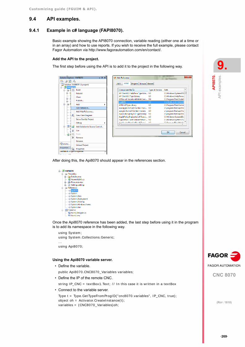
Customizing guide (FGUIM & API).
CNC 8070
AP
I80
70.
9.
AP
I exa
mp
les.
·269·
(REF: 1810)
9.4 API examples.
9.4.1 Example in c# language (FAPI8070).
Basic example showing the API8070 connection, variable reading (either one at a time orin an array) and how to use reports. If you wish to receive the full example, please contactFagor Automation via http://www.fagorautomation.com/en/contact/.
Add the API to the project.
The first step before using the API is to add it to the project in the following way.
After doing this, the Api8070 should appear in the references section.
Once the Api8070 reference has been added, the last step before using it in the programis to add its namespace in the following way.
using System;using System.Collections.Generic;...using Api8070;
Using the Api8070 variable server.
• Define the variable.
public Api8070.CNC8070_Variables variables;
• Define the IP of the remote CNC.
string IP_CNC = textBox1.Text; // In this case it is written in a textBox
• Connect to the variable server.
Type t = Type.GetTypeFromProgID("cnc8070.variables", IP_CNC, true);object oh = Activator.CreateInstance(t);variables = (CNC8070_Variables)oh;
Customizing guide (FGUIM & API).
CNC 8070
9.
AP
I80
70.
AP
I exa
mp
les.
·270·
(REF: 1810)
• Subscribing to variable server events (reports).
SubscribeToEvents(); (This function is explained in the report management).
• Open a variable.
int id = variables.OpenVariable(varName);
• Read a variable.
string textoProg = variables.ReadTxt(idProg, -1);
• Write an array of variables.
int error = variables.WriteVarArray(ref ids, ref values);
• Close a variable (must be done for all opened variables).
variables.CloseVariable(id);
Using reports.
• Open a variable.
int idProg = variables.OpenVariable("G.FILENAME");
• Verify if the indicated variable is from report, and if so, connect to the report.
if (variables.IsReport(idProg) == 1)variables.OpenReport(idProg);
• To subscribe to the variable events, you must first call the function SubscribeToEvents().
private bool EventsSubscribed = false;private void SubscribeToEvents(){
if (EventsSubscribed)return;
elseEventsSubscribed = true;
variables.Report += variables_Report;}
• If the received report is for the subscribed variable, read the value of the variable.
private void variables_Report(int param1, object param2){
if (variables.HandleReport(idProg, param1, param2) != 0){
//Read variable.textoProg = variables.ReadTxt(idProg, -1);
}}
• Close the report
variables.CloseReport(idProg)
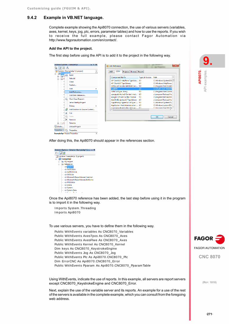
Customizing guide (FGUIM & API).
CNC 8070
AP
I80
70.
9.
AP
I exa
mp
les.
·271·
(REF: 1810)
9.4.2 Example in VB.NET language.
Complete example showing the Api8070 connection, the use of various servers (variables,axes, kernel, keys, jog, plc, errors, parameter tables) and how to use the reports. If you wishto rece ive the fu l l example , p lease con tac t Fagor Au tomat ion v iahttp://www.fagorautomation.com/en/contact/.
Add the API to the project.
The first step before using the API is to add it to the project in the following way.
After doing this, the Api8070 should appear in the references section.
Once the Api8070 reference has been added, the last step before using it in the programis to import it in the following way.
Imports System.ThreadingImports Api8070
To use various servers, you have to define them in the following way.
Public WithEvents variables As CNC8070_VariablesPublic WithEvents AxesTpos As CNC8070_AxesPublic WithEvents AxesFlwe As CNC8070_AxesPublic WithEvents Kernel As CNC8070_KernelDim keys As CNC8070_KeystrokeEnginePublic WithEvents Jog As CNC8070_JogPublic WithEvents Plc As Api8070.CNC8070_PlcDim ErrorCNC As Api8070.CNC8070_ErrorPublic WithEvents Pparam As Api8070.CNC8070_PparamTable
Using WithEvents, indicate the use of reports. In this example, all servers are report serversexcept CNC8070_KeystrokeEngine and CNC8070_Error.
Next, explain the use of the variable server and its reports. An example for a use of the restof the servers is available in the complete example, which you can consult from the foregoingweb address.
Customizing guide (FGUIM & API).
CNC 8070
9.
AP
I80
70.
AP
I exa
mp
les.
·272·
(REF: 1810)
Using the Api8070 variable server.
• Define the variable.
Public WithEvents variables As CNC8070_Variables
• Define the IP of the remote CNC.
Dim IP_CNC As StringIP_CNC = TextBoxIP_CNC.Text // In this case it is written in a textBox
• Connect to the variable server.
variables = CreateObject("cnc8070.variables", IP_CNC)
• Open a variable.
Dim pVarStatus As IntegerpVarStatus = variables.OpenVariable("G.STATUS")
• Read a variable.
Dim textStatus As StringtextStatus = variables.ReadTxt(pVarStatus, -1)
• Read and write an array of variables that are not report variables.
...Dim varsRead (2) As Object 'Id of the variables to be readDim varsWrite (2) As Object 'Id of the variables to be writtenDim readValues As Object ' Array of readed valuesDim funStatus As Integer 'status of the function read/writeDim namevariablesRead (2) As String 'name of the variables to be readDim namevariablesWrite (2) As String 'name of the variables to be written
namevariablesRead(0) = "PLC.R[200]"...namevariablesWrite(0) = "PLC.R[100]"...
'Open all variables defined in the arraysFor i = 0 To UBound(namevariablesRead)
varsRead(i) = variables.OpenVariable(namevariablesRead(i))NextFor i = 0 To UBound(namevariablesWrite)
varsWrite(i) = variables.OpenVariable(namevariablesWrite(i))Next
'Read variablesfunStatus = variables.ReadDoubleArray(varsRead, readValues)...
'Write variablesfunStatus = variables.WriteDoubleArray(varsWrite, readValues)...
'Close all open variablesFor i = 0 To UBound(namevariablesRead)
variables.CloseVariable(varsRead(i))NextFor i = 0 To UBound(namevariablesWrite)
variables.CloseVariable(varsWrite(i))Next
• Close a variable (must be done for all opened variables).
variables.CloseVariable(pVarStatus)
Customizing guide (FGUIM & API).
CNC 8070
AP
I80
70.
9.
AP
I exa
mp
les.
·273·
(REF: 1810)
Using reports.
• Open a variable.
pVarStatus = variables.OpenVariable("G.STATUS")
• Verify if the indicated variable is from report, and if so, connect to the report.
If (variables.IsReport(pVarStatus)) Thenret = variables.OpenReport(pVarStatus)
End If
• If the received report is for the subscribed variable, read the value of the variable.
Private Sub variables_Report(ByVal param1 As Integer, ByVal param2 As Object) Handles variables.Report
If (variables.HandleReport(pVarStatus, param1, param2)) Then'Read variable.textStatus = variables.ReadTxt(pVarStatus, -1)Me.TextBoxStatus.Text = textStatusMe.Refresh()
End IfEnd Sub
• Close the report
variables.CloseReport(pVarStatus)
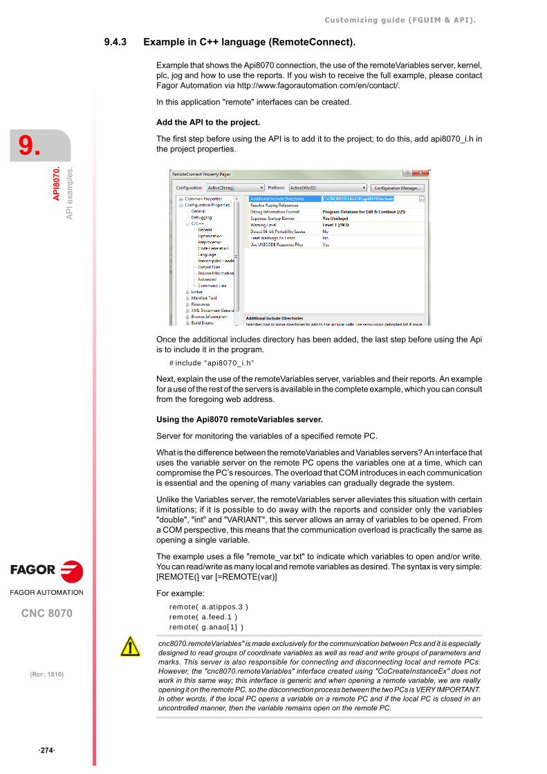
Customizing guide (FGUIM & API).
CNC 8070
9.
AP
I80
70.
AP
I exa
mp
les.
·274·
(REF: 1810)
9.4.3 Example in C++ language (RemoteConnect).
Example that shows the Api8070 connection, the use of the remoteVariables server, kernel,plc, jog and how to use the reports. If you wish to receive the full example, please contactFagor Automation via http://www.fagorautomation.com/en/contact/.
In this application "remote" interfaces can be created.
Add the API to the project.
The first step before using the API is to add it to the project; to do this, add api8070_i.h inthe project properties.
Once the additional includes directory has been added, the last step before using the Apiis to include it in the program.
#include "api8070_i.h"
Next, explain the use of the remoteVariables server, variables and their reports. An examplefor a use of the rest of the servers is available in the complete example, which you can consultfrom the foregoing web address.
Using the Api8070 remoteVariables server.
Server for monitoring the variables of a specified remote PC.
What is the difference between the remoteVariables and Variables servers? An interface thatuses the variable server on the remote PC opens the variables one at a time, which cancompromise the PC’s resources. The overload that COM introduces in each communicationis essential and the opening of many variables can gradually degrade the system.
Unlike the Variables server, the remoteVariables server alleviates this situation with certainlimitations; if it is possible to do away with the reports and consider only the variables"double", "int" and "VARIANT", this server allows an array of variables to be opened. Froma COM perspective, this means that the communication overload is practically the same asopening a single variable.
The example uses a file "remote_var.txt" to indicate which variables to open and/or write.You can read/write as many local and remote variables as desired. The syntax is very simple:[REMOTE(] var [=REMOTE(var)]
For example:
remote( a.atippos.3 )remote( a.feed.1 )remote( g.anao[1] )
cnc8070.remoteVariables" is made exclusively for the communication between Pcs and it is especiallydesigned to read groups of coordinate variables as well as read and write groups of parameters andmarks. This server is also responsible for connecting and disconnecting local and remote PCs.However, the "cnc8070.remoteVariables" interface created using "CoCreateInstanceEx" does notwork in this same way; this interface is generic and when opening a remote variable, we are reallyopening it on the remote PC, so the disconnection process between the two PCs is VERY IMPORTANT.In other words, if the local PC opens a variable on a remote PC and if the local PC is closed in anuncontrolled manner, then the variable remains open on the remote PC.
Customizing guide (FGUIM & API).
CNC 8070
AP
I80
70.
9.
AP
I exa
mp
les.
·275·
(REF: 1810)
• Create the remote object:
LPUNKNOWN lpUnknown;SCODE sc;...lpUnknown = CreateObjectEx( _T("cnc8070.remoteVariables"), _T(""), 0 );...lpUnknown->QueryInterface(IID_IFCDualRemoteVar8070, (void **)&m_pDualRemoteVar);lpUnknown?Release();
• Open a variable.
m_pDualRemoteVar->OpenVariable(bstr_PcIdent, bstr_csVar, &pReadWriteVars->m_hVarRead);
• Read an array of variables.
m_pDualRemoteVar->ReadDoubleArray( &m_arrayhRemoteVarRead, &arrayValueRemoteRead, &ret );
• Write an array of variables.
m_pDualRemoteVar->WriteDoubleArray( &m_arrayhRemoteVarWrite, &m_arrayValueRemoteWrite, &ret );
• Close a variable.
m_pDualRemoteVar->CloseVariable( pReadWriteVars->m_hVarRead, &ret );
Using the Api8070 variable server.
• Create the remote object:
MULTI_QI qi[] = {{&IID_IFCDualVar8070, NULL, S_OK},...
};
progid = L"cnc8070.Variables";::CLSIDFromProgID(progid, &clsid);
hResult = (pfCoCreateInstanceEx)(clsid, NULL, CLSCTX_REMOTE_SERVER, &serverInfo, 1, &qi[0]);...m_pRemoteVarServer = (IFCDualVar8070*)qi[0].pItf;...IFCDualVar8070 *pDualVar = (IFCDualVar8070 *)m_pRemoteVarServer;
• Open a variable.
pDualVar->OpenVariable( bstr_csVar, &pReadWriteVars->m_hVarWrite );
• Read an integer variable.
pDualVar->ReadInt( hVar, NO_HVAR_INDEX, NO_HVAR_INDEX, &nValue );
• Read a double variable array.
pDualVar->ReadDoubleArray( &m_arrayhLocalVarRead, &arrayValueLocalRead, &ret );
• Write a double variable array.
pDualVar->WriteDoubleArray( &m_arrayhLocalVarWrite, &m_arrayValueLocalWrite, &ret );
• Close a variable.
pDualVar->CloseVariable( pReadWriteVars->m_hVarRead );
Using reports.
• Once the variable is open, check if the indicated variable is a report, and if so, connectto the variable server and open a report for the indicated variable.
FCReportVar *m_pReport;...pDualVar->IsReport( hVar, &bIsReport );if( bIsReport){
m_pReport = new FCReportVar();m_pReport->SetParent( this ); // Variable reportm_pReport->ConnectServer(pDualVar);
Customizing guide (FGUIM & API).
CNC 8070
9.
AP
I80
70.
AP
I exa
mp
les.
·276·
(REF: 1810)
pDualVar->OpenReport( hVar, &ret);}
• Report management
LRESULT CRemoteConnectDlg::VariableReport( WPARAM param1, LPARAM param2 ){
...
int nMax = m_hVarArray.GetSize();long hVar;for( int i = 0; i < nMax; i++ ){
hVar = m_hVarArray[i];bHandleReport = FALSE;pDualVar->HandleReport(hVar, param1, (const VARIANT FAR&)(*(long *)param2),&bHandleReport );if( bHandleReport ){
... // Perform a corresponding action for the variable hVar}
}return 1;
}
• Close the report for each variable.
pDualVar->CloseReport(hVar, &ret);

Customizing guide (FGUIM & API).
CNC 8070
·277·
User notes:
(REF: 1810)

Customizing guide (FGUIM & API).
CNC 8070
·278·
User notes:
(REF: 1810)

Customizing guide (FGUIM & API).
CNC 8070
·279·
User notes:
(REF: 1810)

Fagor Automation S. Coop.Bº San Andrés, 19 - Apdo. 144E-20500 Arrasate-Mondragón, SpainTel: +34 943 719 200
+34 943 039 800Fax: +34 943 791 712E-mail: [email protected]