Embed Size (px)
Citation preview

2058 | New J. Chem., 2014, 38, 2058--2065 This journal is©The Royal Society of Chemistry and the Centre National de la Recherche Scientifique 2014
Cite this: NewJ.Chem., 2014,
38, 2058
Comprehensive study of the templating effect onthe ZnO nanostructure formation within poroushard membranes†
Carminna Ottone,a Katarzyna Bejtka,a Angelica Chiodoni,a Vivian Farıas,b
Ignazio Roppolo,a Giancarlo Canavese,a Stefano Stassi*ab and Valentina Cauda*a
ZnO nanowires were synthesized by combining the template-assisted method with three different ZnO
growth approaches, i.e. sol–gel, aqueous chemical growth, and electrodeposition. We obtained nanostructures
of 200, 50, and even 5 nm diameter in porous alumina and ordered mesoporous silica membranes, showing
effective filling of the template channels and the formation of oriented ZnO nanostructures.
Introduction
ZnO material, showing a wurtzite crystalline structure, is aprominent example of both piezoelectric and semiconductingmaterials. It can be grown in several reproducible ways such asaqueous chemical growth, chemical vapor deposition, sol–gel,etc.1 Nanostructured zinc oxide can find unique applications innanotechnology such as energy nanogeneration, sensing ofmolecules and ion species, as well as in field effect transistors,photovoltaics and optoelectronics.2 The synthesis of ZnO nano-wire (NW) arrays for energy harvesting applications couldbenefit from the presence of a supporting host membrane.Micrometer-long and vertically oriented NWs can be thereforeobtained, separated from each other by an insulating matrixand well mechanically supported. One of the most used tem-plates for supporting both inorganic and organic structures isthe porous anodic aluminum oxide (AAO). A two-step anodiza-tion method is appropriate to achieve a profound control of thealumina thickness and pore size, as demonstrated by Masudaand Fukuda in 1995.3,4 The nanowires hosted in such amembrane would be produced with a controlled length anddiameter, presenting a highly ordered structure and a narrowpore diameter distribution. The electrodeposition method isa conventional technique used to fill the alumina channelswith wurtzitic ZnO nanostructures.1,4 The synthesis of nano-structured and crystalline ZnO by aqueous chemical growth wasalso widely studied on flat substrates, where self-standing
nanowires were obtained.5 However, this technique was rarelycombined with a template approach, which, on the other hand,gives the advantage of synthesizing ZnO nanowires well supportedand separated from each other by an insulating membrane.6
Similarly, the sol–gel approach was also widely studied for thedeposition of thin ZnO films, but seldom used for the growthof nanowires in a templating alumina matrix.7 In the presentwork, we report on the synthesis of confined ZnO nanowires byusing sol–gel, aqueous chemical growth, and electrodepositionapproaches in the channels of three different templates.We studied the process using both commercial (Scheme 1a)and lab-made (Scheme 1b) AAO membranes. In order to inves-tigate the confinement effect on the ZnO nanostructures down
Scheme 1 Types of porous templates used in this work: (a) commercialand (b) laboratory-made porous anodic aluminum oxide (AAO), (c) orderedmesoporous silica (OMS) in commercial AAO. For each template both top-down electron microscopy images and schemes of the overall hoststructure (not in scale) are shown. (d) Scheme of the host matrix impreg-nation with ZnO precursors leading to an array of vertically aligned ZnOnanowires supported in the template.
a Center for Space Human Robotics @Polito, Istituto Italiano di Tecnologia,
Corso Trento, 21, Turin, Italy. E-mail: [email protected];
Fax: +39 011 090 3401; Tel: +39 011 090 3436b Politecnico di Torino, Dipartimento di Scienza Applicata e Tecnologia (DISAT),
Corso Duca Degli Abruzzi, 24, Turin, Italy
† Electronic supplementary information (ESI) available. See DOI: 10.1039/c3nj01135f
Received (in Montpellier, France)20th September 2013,Accepted 9th December 2013
DOI: 10.1039/c3nj01135f
www.rsc.org/njc
NJC
PAPER

This journal is©The Royal Society of Chemistry and the Centre National de la Recherche Scientifique 2014 New J. Chem., 2014, 38, 2058--2065 | 2059
to the nanometric level, we also studied the templating effect ofa mesoporous silica membrane (Scheme 1c), which is anamorphous SiO2 network with oriented and ordered poresof the same size, distributed following a specific symmetry(hexagonal, cubic, or lamellar) and synthesized through a self-assembly surfactant-assisted method.8 ZnO nanoparticles werealready incorporated into ordered silica matrices in powderform by using functionalizing agents.9 Here, to obtain a tem-plating structure showing columnar pores with the same size,we have synthesized the OMS in the channels of the commer-cial alumina membrane, as previously reported.10 We obtainedindeed collinear and oriented mesopores of around 5–9 nm indiameter, distributed with a hexagonal symmetry with the poreaxis direction parallel to the alumina channel (Scheme 1c).Such a mesoporous host as well as the commercial AAOmembrane have been already used as templates for preparingultra-thin polymeric nanowires with enhanced piezoelectricproperties.11 In this work we have filled the columnar meso-pores in the alumina membranes with the ZnO precursors,using all the three approaches, i.e. sol–gel, aqueous chemicalgrowth, and electrodeposition, mentioned above for thealumina filling. The general aim of this work is to study boththe advantages and disadvantages of each impregnation strategyin the different porous membranes for the formation of ZnOnanostructures. In addition we are interested in understandingthe scaling-down effect of ZnO formation in the tiny pores ofthe OMS hosts. The proposed ZnO-templated nanostructurescould find potential application as mechanical energy nano-harvesters, being easy to handle, and integrate in a workingdevice. In addition, such nanosized and customized materialscan be easily electrically connected from the top and thebottom of the supporting membrane and maintain goodmechanical compactness and stability.
Experimental sectionSynthesis of the template
Lab-made anodic aluminum oxide (AAO). For the prepara-tion of the AAO membranes, a 1.5 cm � 1.5 cm aluminum foil(99.998% purity, 0.5 mm thick, from Alfa Aesar) was mechani-cally polished using diamond paste and degreased by sonica-tion in acetone and ethanol. A mirror-like aluminum surfacewas obtained by electropolishing at constant current (450 mA)for 5 minutes in 5 : 1 v/v of absolute ethanol (98%, SigmaAldrich) and perchloric acid (HClO4 60%, Sigma Aldrich). Thefirst anodization was carried out with oxalic acid dihydrate(Zn(CH3COO)2�2H2O, Merck Chemicals, hereafter Zn(AC)) at40 V for 1 h at 5 1C, then the alumina was etched with 5 wt%phosphoric acid (80% v/v, Merck Chemicals). A second anodi-zation performed under the same conditions for 20 hoursresulted in a 60 mm thick membrane. Finally, the 5 wt%solution of phosphoric acid at RT was again used to enlargethe pores up to 50 nm in diameter. Free-standing nanoporousAAO membranes were obtained by chemically etching theremaining aluminum substrate by immersion in a saturated
solution of copper(II) chloride dihydrate (CuCl2�2H2O). Theremoval of the alumina barrier layer, at the bottom of thechannels, was achieved by etching in a solution of 5 wt%phosphoric acid for 1 h at RT.
Commercial anodic aluminum oxide. The commercial AAOhaving a nominal pore size of 200 nm and a thickness of 60 mmwas supplied by Whatman (Anodiscs, 47 mm in diameter).
Ordered mesoporous silica (OMS) in commercial aluminamembranes. The precursor solutions used for the fabrication ofordered mesoporous silica were prepared by applying the pre-viously reported two-step synthesis procedure.10 In particular, theEvaporation Induced Self-Assembly (EISA) process consists of therapid solvent evaporation of the silica precursor solution, drivingthe self-assembly process towards the critical micelle concen-tration and the formation of the liquid-crystal mesophase.10
ZnO impregnation methods
Sol–gel. The sol–gel (SG) solution was prepared by mixing5.49 g (25 mM) of Zn(AC) in 47.6 mL of ethanol. The suspensionwas heated at 80 1C, then 2.4 mL of diethanolamine (DEA) wasdropped under continuous stirring. The mixture was refluxed at80 1C for 1 h. The alumina impregnation was performed byinserting the commercial AAO-template into an empty round-bottom flask and evacuating for 5 min. Then, 1 mL of solutionwas injected into the flask. The system was maintained undervacuum conditions for 30 min and then backfilled withambient air. The samples were pyrolyzed in air at 300 1C for10 min to remove the organic fraction. Finally the samples wereannealed in air at 500 1C for 2 h (heating rate of 0.5 1C min�1) inorder to crystallize the ZnO material.
Aqueous chemical growth (ACG). The aqueous chemicalgrowth (ACG) of ZnO nanorods within the three differenttemplate channels was performed by immersing the mem-branes in a growth solution of 50 mM zinc nitrate hexahydrate(Zn(NO3)2�6H2O), 25 mM hexamethylenetetramine (HMT),1.5 mM polyethyleneimine (PEI, Mw = 800 g mol�1, end capped)and 320 mM ammonium hydroxide in bi-distilled water (totalvolume 50 mL) and maintained at 88 1C for 1 to 5 h understirring. No further thermal treatment was required for obtaininga crystalline material.
Electrodeposition. To electrically contact the commercialalumina surface for electrodeposition (ED), gold (Au) electrodes(about 100 nm thick) were sputtered on one side of the AAOmembrane by means of a Q150TES (Quorum Technology)sputtering system, operating at 55 mA for 120 s at roomtemperature and 8 � 10�4 mbar. For the lab-made AAO, theremaining aluminum at the bottom was used as the workingelectrode, whereas dissolution of the barrier layer was per-formed with 5% w/w phosphoric acid. In both cases, platinumfoil served as a counter electrode. The electrolyte solution usedfor ZnO deposition consisted of 0.01 M zinc nitrate hexahydratein bi-distilled water and the ED was performed at 2.5 V, 85 1Cfor 2 to 5 hours.4 Also in this case, no additional thermaltreatment was required.
At the end of the impregnation processes, to selectivelydissolve the alumina membrane for FESEM imaging, a small
Paper NJC

2060 | New J. Chem., 2014, 38, 2058--2065 This journal is©The Royal Society of Chemistry and the Centre National de la Recherche Scientifique 2014
piece of sample was immersed in a solution of 0.5 M NaOH and0.03 M Zn(AC) and maintained at 80 1C for 3 h.12
Characterization methods
The morphological and compositional characterization of theZnO impregnated samples were performed by Field EmissionScanning Electron Microscopy (FESEM, ZEISS Dual Beam Auriga)equipped with an Energy Dispersive X-ray spectrometer (EDS, IncaXSight; Oxford Instruments). Transmission Electron Microscopywas performed using a FEI Tecnai F20ST operating at 200 kVequipped with EDS (EDAX). An X-ray diffraction (XRD) system witha Cu-Ka X-ray tube (l = 1.542 Å) with an accelerating voltage of40 kV was used to characterize the crystalline structure of the zincoxide confined in the pore of the alumina membranes. For themesoporous silica templates, nitrogen sorption isotherms weremeasured using a Quadrasorb SI instrument (Quantachrome). Themultipoint BET surface area was measured within the relativepressure range of 0.1–0.3 p/p0. A Non-Local Density FunctionalTheory (NLDFT) equilibrium model of N2 on silica was applied toestimate the pore volume and the pore size distribution.
Results and discussionImpregnation of commercial AAO
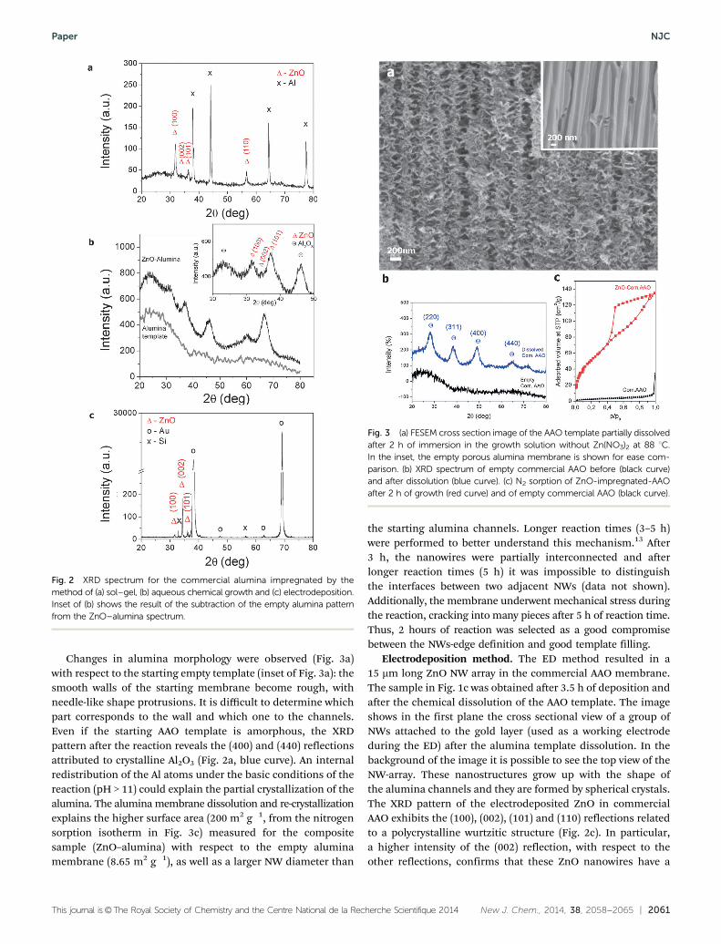
Sol–gel method. In order to obtain the nanowire morphology,it would be required to repeat the impregnations with the sol untilthe ZnO nanoparticles completely fill the channels. Slower fillingrates were observed when the subsequent impregnation wasimmediately performed without a pyrolysis step in between.Thermogravimetrical measurements (see ESI†) showed thatthermal treatment at 300 1C led to the removal of the organicmoieties after each impregnation, leaving a high free volume inthe alumina channels for further impregnations. In this thermallycontrolled process, the formation of ZnO nanoparticles attachedto the AAO-membrane channels takes place by the decom-position of Zn(AC) and DEA. The FESEM image (Fig. 1a) of a9-impregnation sol–gel sample shows that the alumina channelfilled with ZnO wurtzitic crystals consists of an agglomerationof nanoparticles having 15–30 nm in diameter. The XRDpattern in Fig. 2a shows a wurtzite-like crystalline structure,with (100), (002), (101) and (110) reflections of ZnO. The averagecrystal size of the synthesized ZnO nanostructures calculatedusing the Debye–Scherrer equation from the XRD pattern is17.5 nm. This value is in agreement with the crystal sizesmeasured from FESEM. The amorphous broad band in therange of 20–401 could be attributed to the amorphous porousalumina membrane, whereas the sharp peaks attributed toaluminum are related to the XRD sample holder. We proposethat the impregnation of the AAO channels by ZnO starts withsmall crystal nucleation at the alumina walls and afterwards thecrystals grow, filling the channels from the perimeter to thecenter (outside-in direction).
Aqueous chemical growth approach. The FESEM image(Fig. 1b) of the sample obtained by ACG after 2 h of immersionin the growth solution reveals the complete filling of the
template channels and an enlargement of their diameter.We observed by FESEM that NWs with a larger diameter (about300 nm) than the respective AAO template (200 nm) wereproduced. In addition, after chemical etching, the NWs main-tain the template shape and have a granular surface (see theinset of Fig. 1b). The XRD pattern (Fig. 2b) reveals the presencenot only of ZnO, but also of crystalline alumina. With the scopeof having XRD peaks better identified, we have subtracted fromthis spectrum the XRD pattern of empty alumina (see the insetof Fig. 2b). ZnO peaks at 31.91, 34.41 and 36.91, correspondingto the (100), (002) and (101) reflections, respectively, can beclearly observed.
A blank AAO sample was prepared by immersing the AAOmembrane in the solution without the Zn(NO3)2 reactant.In this way we aim to better understand the chemical processwhich the AAO template underwent during impregnation in theACG bath, and thus to explain the FESEM and XRD results.
Fig. 1 FESEM cross-section images of nanostructures within the pores ofcommercial alumina templates synthesized by: (a) the sol–gel method, (b) theaqueous chemical growth approach and the (c) electrodeposited methodafter template removal. The insets of (b and c) show the magnified FESEMimages of extracted ZnO wires after the AAO template dissolution.
NJC Paper
This journal is©The Royal Society of Chemistry and the Centre National de la Recherche Scientifique 2014 New J. Chem., 2014, 38, 2058--2065 | 2061
Changes in alumina morphology were observed (Fig. 3a)with respect to the starting empty template (inset of Fig. 3a): thesmooth walls of the starting membrane become rough, withneedle-like shape protrusions. It is difficult to determine whichpart corresponds to the wall and which one to the channels.Even if the starting AAO template is amorphous, the XRDpattern after the reaction reveals the (400) and (440) reflectionsattributed to crystalline Al2O3 (Fig. 2a, blue curve). An internalredistribution of the Al atoms under the basic conditions of thereaction (pH > 11) could explain the partial crystallization of thealumina. The alumina membrane dissolution and re-crystallizationexplains the higher surface area (200 m2 g�1, from the nitrogensorption isotherm in Fig. 3c) measured for the compositesample (ZnO–alumina) with respect to the empty aluminamembrane (8.65 m2 g�1), as well as a larger NW diameter than
the starting alumina channels. Longer reaction times (3–5 h)were performed to better understand this mechanism.13 After3 h, the nanowires were partially interconnected and afterlonger reaction times (5 h) it was impossible to distinguishthe interfaces between two adjacent NWs (data not shown).Additionally, the membrane underwent mechanical stress duringthe reaction, cracking into many pieces after 5 h of reaction time.Thus, 2 hours of reaction was selected as a good compromisebetween the NWs-edge definition and good template filling.
Electrodeposition method. The ED method resulted in a15 mm long ZnO NW array in the commercial AAO membrane.The sample in Fig. 1c was obtained after 3.5 h of deposition andafter the chemical dissolution of the AAO template. The imageshows in the first plane the cross sectional view of a group ofNWs attached to the gold layer (used as a working electrodeduring the ED) after the alumina template dissolution. In thebackground of the image it is possible to see the top view of theNW-array. These nanostructures grow up with the shape ofthe alumina channels and they are formed by spherical crystals.The XRD pattern of the electrodeposited ZnO in commercialAAO exhibits the (100), (002), (101) and (110) reflections relatedto a polycrystalline wurtzitic structure (Fig. 2c). In particular,a higher intensity of the (002) reflection, with respect to theother reflections, confirms that these ZnO nanowires have a
Fig. 2 XRD spectrum for the commercial alumina impregnated by themethod of (a) sol–gel, (b) aqueous chemical growth and (c) electrodeposition.Inset of (b) shows the result of the subtraction of the empty alumina patternfrom the ZnO–alumina spectrum.
Fig. 3 (a) FESEM cross section image of the AAO template partially dissolvedafter 2 h of immersion in the growth solution without Zn(NO3)2 at 88 1C.In the inset, the empty porous alumina membrane is shown for ease com-parison. (b) XRD spectrum of empty commercial AAO before (black curve)and after dissolution (blue curve). (c) N2 sorption of ZnO-impregnated-AAOafter 2 h of growth (red curve) and of empty commercial AAO (black curve).
Paper NJC

2062 | New J. Chem., 2014, 38, 2058--2065 This journal is©The Royal Society of Chemistry and the Centre National de la Recherche Scientifique 2014
preferential orientation along the vertical axis of the aluminaporous template, i.e. the c-axis of the ZnO NWs. There is noevidence of template dissolution during the impregnationprocess. The use of a weak acid solution (pH = 5.9) containingonly zinc nitrate avoids indeed the interaction with the aluminaduring the ZnO formation.
As a first conclusion, both the ACG and the ED processeshave the advantage of forming crystalline ZnO NWs, withoutany further thermal treatment.
Impregnation of lab-made AAO
The above techniques for the ZnO deposition were repeatedusing as matrix a lab-made alumina with smaller pore size(about 50 nm in diameter) with respect to the commercialmembranes (about 200 nm). The aim is to reduce the freechannel volume by taking advantage of the possibility ofcontrolling the length and size of the AAO channels.
Sol–gel method. Fig. 4a shows the sample synthesized by thesol–gel method with 3 impregnations. In this case, only fewchannels were filled with ZnO structures. This is probably dueto the FESEM sample preparation resulting in the detachmentof some particles from the channel wall. In this case, thesample was mechanically cut into two pieces to observe thecross-section. It is important to notice that for this membranethe number of impregnations (3 times) is much smaller incomparison with the 9 impregnations used for the commercialAAO templates. Therefore, it is reasonable to observe onlyisolated ZnO crystals, rather than broader aggregates or con-tinuous structures. As a consequence, a low filling volume ofthe alumina pores is obtained and for this reason no wurtzitediffraction peak could be detected by XRD (not shown). However,evidence of the Zn element from EDX analysis confirmed thatthe nucleation of ZnO material took place (as representativelyshown in Fig. 5a).
Aqueous chemical growth approach. Fig. 4b shows theFESEM image corresponding to the ZnO–AAO sample preparedby the ACG for 2 h. In this case the channels are completelyfilled by ZnO NWs. Few AAO channels seem empty or notcompletely filled, but this could again be attributed to thecross-section preparation technique. The image inset showsthe free NWs, obtained after chemical etching of the template.Dissolution of the alumina during the impregnation processwas also observed and confirmed by the enlargement of thechannel from 50 nm to 80 nm for 2 h of ZnO reaction. Similarly,the alumina diffraction peaks (220), (311) and (400) can beobserved in the XRD spectrum of this sample (see Fig. 5b). It isworthy of note that the ZnO NWs have a preferential growthdirection, confirmed by the presence of only the (002) reflec-tion. As observed with the commercial alumina matrix, withreaction times longer than 2 h, the alumina walls becomethinner until a complete merge between the matrix and theZnO composite is reached. The dissolution of the template ishigher when thinner (o60 mm) membranes are used, thus theoptimal reaction time in this case should be less than 2 hours.Therefore the thickness and the channel size of the templatestrongly influence the allowed ZnO growth time.
Electrodeposition method after template removal. The ED ofZnO within the channels of AAO membranes was carried outusing the remaining aluminum foil as a working electrode. TheZnO started to nucleate and grow at the bottom of the aluminachannel. The FESEM image of the sample in cross-section(Fig. 4c) shows that most of the channels are filled. Also forthis sample we attribute this effect to the partial detachment ofthe ZnO NWs during the sample preparation for FESEM char-acterization. In addition, the incomplete dissolution of thebarrier layer at the bottom of some channels could also preventa proper electric contact and an ED process. However, longerdissolution times with phosphoric acid, used to etch the barrierlayer, would also yield broader channel diameters. This effectis not desired in the present study, since the AAO channel
Fig. 4 FESEM image of nanowires within the pores of lab-made aluminatemplates (AAO) obtained by (a) sol–gel method, (b) aqueous chemicalgrowth and (c) electrodeposition.
NJC Paper

This journal is©The Royal Society of Chemistry and the Centre National de la Recherche Scientifique 2014 New J. Chem., 2014, 38, 2058--2065 | 2063
diameter would then approach the pore size of commercialanodic alumina. The electrodeposited ZnO NWs fill completelythe AAO membrane channels, meaning that they are as long asthe thickness of the alumina, i.e. 60 mm. The presence of Zn wasalso confirmed by EDX (data not shown). The XRD spectrumin Fig. 5c shows the presence of polycrystalline ZnO wurtziticstructure.
Impregnation of OMS
The ordered mesoporous silica (OMS) is constituted by bimodalmesopores of 5.6 and 9.6 nm in diameter, calculated from theN2 sorption isotherms (Fig. 9, black curve).
Sol–gel method. Fig. 6 shows the cross-section FESEM imageof the OMS obtained upon impregnation of the template withsol–gel ZnO-precursor-solution after 13 impregnations.
This sample shows quasi-spherical nanostructures formedinside the AAO channels in the range 13 to 50 nm (see whitebars in the inset in Fig. 6a, representing the particle sizes).
In some areas inside the AAO channels the material seems to beagglomerated into a more compact structure, covering the wallswith a ZnO layer. However, the top view image (here not shown)reveals the presence of a dense layer of ZnO on the AAO surface,blocking further liquid penetration into the mesopores. The XRDpattern shows indeed the ZnO wurtzitic polycrystalline structure,thus with randomly oriented crystals (Fig. 6b). Unfortunately,further magnification of the FESEM image reveals that themesostructured silica is no more present within the AAOchannels. In addition, the crystal size of the ZnO nanoparticles,within these templates, is larger than the pore size of silica.We concluded that ZnO nano-crystals were formed in the aluminachannels, while dissolution or detachment of the mesoporoussilica material took place.
Aqueous chemical growth approach. An efficient filling ofthe mesoporous silica membranes with ZnO was obtained by theACG method carried out for 2 h. Bright Field TEM and HRTEMwere used to deeply investigate the impregnation results. Thelamella of the cross section was prepared by Focused Ion Beam.Fig. 7a shows the Bright Field TEM image of the sample at aboutsome micron from the surface. The alumina channels filled withmesoporous silica can be observed. The HRTEM image reportedin Fig. 7b shows the silica channels filled with ZnO nanocrystalsof 5 nm diameter, which is consistent with the mesopore size.The spacing between the channels corresponds to the usuallyreported distance for mesoporous silica structures preparedwith a Pluronic P123 surfactant, confirming that the ZnO
Fig. 5 (a) EDX spectrum (acquired from the top of the sample) of lab-made alumina template impregnated with ZnO by sol–gel. XRD spectrumof lab-made alumina template impregnated with ZnO by the (b) aqueouschemical growth and (c) electrodeposition methods.
Fig. 6 (a) Cross-section FESEM image of ZnO nanostructures prepared bythe sol–gel impregnating method using OMS as template after 13 impreg-nations. Inset shows a magnification in the channel region at the top of themembrane. (b) XRD spectrum of sample in (a).
Paper NJC

2064 | New J. Chem., 2014, 38, 2058--2065 This journal is©The Royal Society of Chemistry and the Centre National de la Recherche Scientifique 2014
nanocrystals are formed inside the silica channels.10,14 Fig. 7cshows the Fast Fourier Transform (FFT) of the image in Fig. 7b,confirming that the obtained structure is crystalline.
The EDX measurements (Fig. 7d) confirmed the presence ofZn in the silica pores. The EDX spectrum puts in evidence alsothe presence of Si and Al, which are the membrane elements,of P which is used for the synthesis of the mesoporous silica,of Ga and Pt which result from the FIB lamella preparationmethod, and finally of Fe and Cu, which result from theinteraction with TEM lenses and the copper grid, respectively.
The nitrogen sorption isotherms of the ZnO–OMS preparedby the ACG method are shown in Fig. 8a. The total surface areaof the sample was reduced from 25 to 10 m2 g�1 after impreg-nation. Additionally, the reduction of the pore size (from 9.7and 5.6 down to 2.8 nm) (Fig. 8b) also reveals the good filling ofthe channels with ZnO crystals.
Electrodeposition method after template removal. Theimpregnation of OMS samples using the electrochemicalmethod resulted in formation of ZnO ultra-thin nanowireswithin the silica mesopores. ZnO-filled silica, presenting a
columnar arrangement within the alumina channels, can beeasily observed in Fig. 9a. This image shows the cross-section ofan electrodeposited sample close to the bottom of the matrix,i.e. where the Au electrode was deposited.
EDX measurements performed in different regions indicatethat Zn is present within the mesopores of silica; a representativespectrum is shown in Fig. 9b. Considering that the analyzed areais at the bottom of the sample, the Al peak is as much intense asthe Zn one. This result is confirmed by the XRD spectrum inFig. 9c. The XRD pattern shows the wurtzitic structure of ZnOwith a preferential orientation along the (002) direction. Theother reflections are attributed to the cubic structure of the goldsputtered electrode.
The nitrogen sorption isotherm and related DFT pore sizedistribution (Fig. 8, red curves) show a consistent reduction of
Fig. 7 FIB lamella of OMS filled with ZnO nanocrystals. (a) Bright FieldTEM. (b) HRTEM. (c) FFT image and (d) the TEM-EDX spectrum.
Fig. 8 (a) Nitrogen sorption isotherms and (b) pore size distributions ofempty (in black) and ZnO-filled OMS membranes by ACG (blue curves) andED methods (red curves).
Fig. 9 (a) Cross-section FESEM image, (b) EDX pattern and (c) XRD spectrumof 3 h-electrodeposited ZnO–OMS membrane.
NJC Paper

This journal is©The Royal Society of Chemistry and the Centre National de la Recherche Scientifique 2014 New J. Chem., 2014, 38, 2058--2065 | 2065
the BET surface area (from 25 to 14 m2 g�1) and pore size (downto 4 nm) after the ED process. This result indicates that themesopores are not completely filled with the ZnO nanowires,the diameter of which is thinner than the mesopore size.
Conclusions
In this work we studied three different impregnation methods,sol–gel, aqueous chemical growth and electrodeposition, forconfining ZnO in porous alumina and mesoporous silicamatrices. All the studied approaches yield the formation ofwurtzitic ZnO nanostructures or nanowires. By using the sol–gel approach and AAO membranes many impregnation cycles(>10) are required to achieve a proper alumina channel filling.Instead, the mesoporous silica structures were washed with therepeated impregnations required by the sol–gel method. TheACG approach yields the formation of nanowires constituted bya heterogeneous mixture of crystalline alumina and ZnO withinthe AAO membrane. In particular, oriented wurtzitic ZnO nano-wires were obtained in the lab-made AAO hosting matrices.However, the template was not chemically stable under the ZnO-growth conditions, leading to dissolution and re-crystallizationprocesses of the alumina matrices, thus long-term processesshould be avoided. In contrast, the ACG method was effective inthe incorporation of oriented ZnO nanocrystals inside the silicamesopores, however no continuous wires were observed. The EDwas the easiest technique to produce polycrystalline ZnO NWsby the template assisted method, both in AAO and OMSmembranes. It is a fast process and could be performed intemplates with different pore sizes without modifying or alter-ing the template characteristics.
The obtained ZnO-templated materials demonstrate a profoundinfluence on the final structure of the ZnO nano-crystals not only bythe nano-confinement effect, but also due to the impregnationmethod and the chemical nature of the hosting material.
Notes and references
1 J. Gomez and O. Tigli, J. Mater. Sci., 2013, 48, 612.2 M. Riaz, J. Song, O. Nur, Z. L. Wang and M. Willander, Adv.
Funct. Mater., 2011, 21, 628; M. Willander and S. Al-Hilli,Micro and Nano Technologies in Bioanalysis, Springer, 2009,pp. 187–200; D. Calestani, M. Zha, R. Mosca, A. Zappettini,M. Carotta, V. Di Natale and L. Zanotti, Sens. Actuators, B,2010, 144, 472.
3 H. Masuda and K. Fukuda, Science, 1995, 268, 1466.4 L. Li, S. Pan, X. Dou, Y. Zhu, X. Huang, Y. Yang, G. Li and
L. Zhang, J. Phys. Chem. C, 2007, 111, 7288.
5 M. Bechelany, A. Amin, A. Brioude, D. Cornu and P. Miele,J. Nanopart. Res., 2012, 14, 1; M. Laurenti, V. Cauda,R. Gazia, M. Fontana, V. F. Rivera, S. Bianco andG. Canavese, Eur. J. Inorg. Chem., 2013, 2520; V. F. Rivera,F. Auras, P. Motto, S. Stassi, G. Canavese, E. Celasco,T. Bein, B. Onida and V. Cauda, Chem.–Eur. J., 2013,19, 14665; L. V. Podrezova, S. Porro, V. Cauda, M. Fontanaand G. Cicero, Appl. Phys. A: Mater. Sci. Process., 2013,113, 623.
6 L. Zhang, Y. Ruan, D. Wang, H. Yang and D. Fang,3rd International Nanoelectronics Conference (INEC),2010; G. S. Wu, T. Xie, X. Y. Yuan, Y. Li, L. Yang,Y. H. Xiao and L. D. Zhang, Solid State Commun., 2005,134, 485.
7 W. Chen, J.-S. Wu and X.-H. Xia, ACS Nano, 2008, 2, 959;X. Lou, H. Shen, H. Zhang and B.-b. Li, Trans. NonferrousMet. Soc. China, 2007, 17, 814; S. Ozturk, N. Tas-altın,N. Kılınç, H. Yuzer and Z. Z. Ozturk, Appl. Phys. A: Mater.Sci. Process., 2010, 99, 73; Y. Zhang, W. Fa, F. Yang, Z. Zhengand P. Zhang, Ionics, 2010, 16, 815.
8 A. G. F. Di Renzo, P. Trens and F. Fajula, in Handbook ofPorous Solids, ed. F. Schuth, K. S. W. Sing and J. Weitkamp,Wiley&Sons, Weinheim, Germany, 2002, p. 13110; J. S. Beck,Method for synthesizing mesoporous crystalline material,US Pat., 5,057,296A; C. Kresge, M. Leonowicz, W. Roth,J. Vartuli and J. Beck, Nature, 1992, 359, 710; J. S. Beck,J. C. Vartuli, W. J. Roth, M. E. Leonowicz, C. T. Kresge, K. D.Schmitt, C. T. W. Chu, D. H. Olson and E. W. Sheppard,J. Am. Chem. Soc., 1992, 114, 10834.
9 P. Lihitkar, S. Violet, M. Shirolkar, J. Singh, O. Srivastava,R. Naik and S. Kulkarni, Mater. Chem. Phys., 2012, 133, 850;Q. Lu, Z. Wang, J. Li, P. Wang and X. Ye, Nanoscale Res. Lett.,2009, 4, 646.
10 V. Cauda, B. Onida, B. Platschek, L. Muhlstein and T. Bein,J. Mater. Chem., 2008, 18, 5888.
11 V. Cauda, S. Stassi, K. Bejtka and G. Canavese, ACS Appl.Mater. Interfaces, 2013, 5, 6430; V. Cauda, B. Torre, A. Falqui,G. Canavese, S. Stassi, T. Bein and M. Pizzi, Chem. Mater.,2012, 24, 4215.
12 D. Ramirez, T. Pauporte, H. Gomez and D. Lincot, Phys.Status Solidi A, 2008, 205, 2371.
13 L. Zhao, M. Steinhart, U. Goesele and S. Schlecht, Adv.Mater., 2008, 20, 1218.
14 T. Lebold, L. A. Muhlstein, J. Blechinger, M. Riederer,H. Amenitsch, R. Kohn, K. Peneva, K. Mullen, J. Michaelisand C. Brauchle, Chem.–Eur. J., 2009, 15, 1661; B. Platschek,N. Petkov and T. Bein, Angew. Chem., 2006, 118, 1152;B. Platschek, R. Kohn, M. Doblinger and T. Bein, Chem-PhysChem, 2008, 9, 2059.
Paper NJC


