Embed Size (px)
Citation preview
GPR, a ground-penetrating radar for the Netlander mission
J. J. Berthelier,1 R. Ney,1 V. Ciarletti,2 A. Reineix,3 B. Martinat,2,3 M. Hamelin,1
F. Costard,4 P. Paillou,5 C. Duvanaud,6 D. Nevejans,7 W. Kofman,8 J. G. Trotignon,9
G. Grandjean,10 M. Zamora,11 and A. Nagy12
Received 13 February 2002; revised 21 June 2002; accepted 3 July 2002; published 8 February 2003.
[1] In the coming decade, several missions are planned that will land on the surface ofMars landers or instrumented geophysical stations. Among the scientific objectives ofthese projects, one of the most important will be to unravel the many unknowns in thegeological and hydrological history of the planet. The Netlander mission offers a uniqueopportunity to explore the interior of Mars, its subsurface, its atmosphere, and its distantenvironment from four landing sites that will be selected to offer a variety of differentgeophysical conditions. We have thus proposed to fly on these four landers a ground-penetrating radar (GPR) to explore the geological characteristics of the subsurface andsearch for water reservoirs down to a depth which may be sufficient to allow a possibledetection of liquid water. We provide in this paper a short description of this radar which isbased on a new concept to allow a 3-D imaging of the subsurface by determining the rangeand direction of the underground reflectors. In order to access to deep layers, it willoperate at a low frequency of 2 MHz. Some results obtained by a numerical modeling ofthe radar operation in an electromagnetic model of the Martian subsurface are presented inorder to illustrate the main capabilities of the radar. In the last section, preliminary resultsfrom an initial field test are reported. In addition to its primary goal as a ground-penetrating radar, the GPR will also be operated on Mars as an ionospheric sounder and, ina passive mode, as a HF receiver to measure the radio-electric background. INDEX
TERMS: 0644 Electromagnetics: Numerical methods; 0994 Exploration Geophysics: Instruments and
techniques; 6225 Planetology: Solar System Objects: Mars; 6297 Planetology: Solar System Objects:
Instruments and techniques; 6994 Radio Science: Instruments and techniques; KEYWORDS: Planetology, Mars,
Mars subsurface, ground-penetrating radar, electromagnetics
Citation: Berthelier, J. J., et al., GPR, a ground-penetrating radar for the Netlander mission, J. Geophys. Res., 108(E4), 8027,
doi:10.1029/2002JE001866, 2003.
1. Introduction
[2] Among the missions which are presently planned tobe flown to Mars during the next decade, a number of
investigations relate to the exploration of the surface andsub-surface of the planet. Getting initial observations of themorphology and structure of the underground at depths ofthe order of a kilometer or more appears of prime interestfor a number of reasons. Accessing the geological featureswhich are present in the subsurface will allow us to improveour understanding of the processes which have been activeduring the formation and evolution of the planet. In partic-ular, it will be extremely interesting to relate them to thedifferent surface features which have been discoveredthrough the initial observations of the Viking spacecraftand have been much better documented in the recent yearsdue to the improved resolution and coverage provided bythe MGS camera [Malin and Edgett, 2000]. As an example,it would be of interest to get subsurface stratigraphic data inoutwash plains where sedimentation is thought to haveoccurred over significant depths [Costard and Kargel,1995], leaving probably layers with different lithologies.Tectonic details and faults have also been detected in anumber of places and probing the subsurface in regionswhere wrinkle ridges are commonly found like LunaePlanum would provide information to test the validity ofthe initial interpretations [Thomas and Masson, 1995;
JOURNAL OF GEOPHYSICAL RESEARCH, VOL. 108, NO. E4, 8027, doi:10.1029/2002JE001866, 2003
1Centre d’Etude des Environnements Terrestre et Planetaires/IPSL,Saint-Maur, France.
2Centre d’Etude des Environnements Terrestre et Planetaires/IPSL,Velizy, France.
3Institut de Recherche en Communications Optiques et Microondes,Universitede Limoges, Limoges, France.
4Orsay-Terre, UniversiteParis-Sud, Orsay, France.5Observatoire Astronomique de Bordeaux, Floirac, France.6LAII, Universitede Poitiers, IUT, Angouleme, France.7BIRA-Institut d’Aeronomie Spatiale de Belgique, Brussels, Belgium.8Laboratoire de Planetologie de Grenoble, Grenoble, France.9Laboratoire de Physique et Chimie de l’Environnement, Orleans la
Source, France.10Bureau de Recherches Geologiques et Minieres, Orleans, France.11Institut de Physique de Globe de Paris, Paris, France.12College of Engineering, University of Michigan, Ann Arbor,
Michigan, USA.
Copyright 2003 by the American Geophysical Union.0148-0227/03/2002JE001866
GDS 8 - 1
Mangold et al., 1998]. Lava layers from volcanic flows,possibly overlapping with sedimentary layers, are also oneof the most interesting targets for Martian geologists.Nevertheless, since water on Mars is the central questionon which are focused most of the coming exploratorymissions, the search for water reservoirs, either in the formof ground ice or of liquid water, is without any doubt themajor objective of all experiments that are related to subsur-face investigation. Even initial observations of the hydrol-ogy of the subsurface would certainly prove to be essentialby providing clues to the most crucial problem of theevolution of the climate and atmosphere of Mars.[3] During the recent years, a number of studies have led
to the idea that, over geological times, the climate of theplanet has evolved from a relatively wet and warm climatewith a strong hydrological cycle including precipitations andthe existence of oceans [Haberle, 1998; Craddock andMaxwell, 1993; Baker et al., 1991] to the presently observedstate of a very tenuous and dry atmosphere. The valleynetworks, mainly found in the old cratered upland, as well asthe presence of runoff and outflow channels [Carr, 2001;Baker, 2001], seem to indicate that a stable water layerexisted on the surface more than 3 billions years ago and thatit persisted in the regolith throughout most of the Martianhistory. Several models have been tested to reproduce agreenhouse effect which would account for such a warm andwet climate [Sagan and Chyba, 1997; Forget and Pierre-humbert, 1997]. From these and other studies, it is thoughtthat the Martian climate evolved through a periglacial phasefrom initial Earth-like conditions, with water present on thesurface in large quantities, to the presently observed state ofa very tenuous and dry atmosphere. Several authors havepresented models that account for the escape of volatiles andtheir subsequent loss to space through various chemical orphysical processes in the upper atmosphere, including inparticular the sputtering of atmospheric constituents byenergetic ions from the solar wind [Luhmann et al., 1992;Hodges, 2002]. The efficiency of these processes, consid-erably enhanced during the early phase of the Solar Systemwith a fast solar wind, may explain the erosion of theatmosphere over geologic times. Simultaneously, and as ithappened in regions with a periglacial climate on the Earth, alarge quantity of water is thought to have gone within theMartian regolith by infiltration and remained stored thereunder the form of ground ice or, even, liquid water.[4] It is thus generally agreed that, below a dry layer, a
large quantity of volatiles still resides within the Martiansubsurface as clay minerals, underground ice, and, possiblyat some depth, liquid water. Several well known surfacefeatures such as the rampart craters formed by meteoriticimpacts [Costard, 1989; Squyres et al., 1992; Barlow et al.,2000] have been used to evaluate the distribution in-depthof the ground ice reservoirs over the different geologicalregions of the planet. This distribution is characterized by alatitudinal variation which relates to the correspondingvariations of the surface temperature: the top of the groundice layer is found at depths of the order of a few hundreds ofmeters in equatorial regions and it is at much smaller depthsat mid to high latitudes where it can be stable at depths of afew tens of meters in Acidalia Planitia or Utopia Planitia[Costard and Kargel, 1995] and even at ground levels sincethe soil temperature is permanently below the freezing point
poleward of 40�. Such values agree quite well with theo-retical estimates of the distribution of volatiles within thecrust [Squyres et al., 1992; Clifford, 1993]. Model estimatesof the permafrost thickness range from 1 to 3 km inequatorial regions to 3 to 7 km at high latitudes [Fanaleet al., 1986]. It is expected that, under ground ice, liquidwater can exist, at least at low latitudes depending on thegeothermal heat flow. The depth of the transition to liquidwater can be reduced significantly by pressure and soluteeffects. New observations from the MGS camera have beenreported [Malin and Edgett, 2000; Mellon and Phillips,2001] showing the existence of recent surface runoff onMars. Such features have been attributed by these authors toerosion by a running fluid and water, that could be formedby groundwater seepage from an underground aquifer, is alikely candidate, although liquid CO2 has been advocatedby Hoffman [2000]. More recently, Costard et al. [2002]have proposed that these landforms may result from themelting of water ice in the top few meters of the Martiansubsurface due to variations of the obliquity of Mars. Theexistences of thermokarst [Mustard et al., 2001], patternground [Mangold and Allemand, 2001], and small polygons[Siebert and Kargel, 2001] are geomorphologic evidencefor the presence of volatile materials during very recentperiods of time [Masson et al., 2001].
2. Objectives and Concept of the GPR on theNetlander Mission
[5] The general objectives of the Netlander missionwhich will deploy the first Geophysical Network on Marshave been described by Counil et al. [2001]. They relate toa variety of scientific subjects which are mostly interdisci-plinary and can be often tackled by means of several of theexperiments that are included in the payload. They coverthe deep interior of the planet, the subsurface and surface,the dynamics of the atmosphere and its interaction with thesurface, and the more distant ionized environment of theplanet. This mission, with its 4 landers, offers a uniqueopportunity to explore the Martian subsurface in 4 differentlocations which can be chosen to represent the mostinteresting samples of Martian sites. In particular, amongthe criteria which will be taken into account to select thelanding areas, definite attention will be given to those thatare related to the subsurface structure and the possibleexistence of water reservoirs at moderate depths as can bepredicted by present-day models. On the Earth, severaltechniques are available to explore the structure and natureof the subsurface. They include the well-developed seismicmethods and the radio-electric techniques, in the form ofeither passive electromagnetic measurements or activesounding by ground-penetrating radar. In planetary explo-ration, and in particular in the case of the rather smalllanders of the Netlander mission, the extremely severeconstraints on mass, power, instrument deployment andoperation make at the moment the ground-penetrating radarpractically the only suitable technique. Originally devel-oped in the early seventies for prospection and geologicalstudies [Annan and Davis, 1976; Arcone, 1981; Wright etal., 1990] it has attracted a large interest also in many moreapplied usages. We have therefore proposed to fly on thelanders a GPR to investigate the geological structures of
GDS 8 - 2 BERTHELIER ET AL.: GPR FOR THE NETLANDER MISSION
the subsurface and possibly detect the presence of waterreservoirs either in the form of ground ice or, even, ofliquid water.[6] These objectives can be met if the range of penetra-
tion of the radar is sufficient compared to the anticipateddepth of the ice and water reservoirs. According to thepapers cited in the previous section, model evaluationsrange from a minimum depth of 100 m for the permafrostroof at low latitudes to 2 to 3 km for the liquid water layernear the equator. A series of measurements of the electro-magnetic properties (electrical permittivity, magnetic per-meability) of various volcanic and sedimentary materialswhich are thought to be fairly good analogs of the expectedMartian materials have been reported recently by Heggy etal. [2002]. From these results, we were led to select a lowfrequency of operation in the MHz range which allows for asufficient penetration depth as will be shown in section 4.Moreover, at such a low frequency, the effect of interfaceroughness and buried objects are less effective to dampenthe waves through diffusion than at the higher frequenciesof tens or hundreds of MHz which are generally used byground-penetrating radars. However, the most challengingdifficulty in operating a ground-penetrating radar on thelanders relates to the fact that these landers will stay infixed locations. On the contrary, the classical way to operatea ground-penetrating radar consists in moving the radarover the ground of interest. From a set of measurementsthat are acquired over a network of different locations, andusing signal analysis techniques similar to those of syn-thetic aperture radars, inversion algorithms [e.g., Habashyand Mittra, 1987] can provide the 3-D structure of theunderground reflectors. In the case of the proposed instru-ment on Netlander which must operate as a true motionlessmonostatic radar, it has therefore been necessary to developa new concept of ground-penetrating radar allowing us todetermine not only the distance of the reflectors but alsotheir direction. Determining the direction of propagationof electromagnetic waves has been the subject of a numberof studies in the last two decades, especially in the case ofsatellite measurements of ionospheric and magnetosphericplasma waves. Several methods have been developed fromthe simple case with a few dominant plane waves [Means,1972; Samson, 1977] to the more complex case of acontinuous wave normal distribution function [Lefeuvreand Delannoy, 1979; Lefeuvre et al., 1981]. Such ananalysis was performed for example on data from thelow-altitude AUREOL-3 spacecraft by Berthelier et al.[1982] and Lefeuvre et al. [1992]. Depending on the signalover noise ratio and the observation time, accuracies of afew degrees to about 10�–15� in worst cases have beentypically estimated. The above mentioned methods arebased on the simultaneous analysis of the electric andmagnetic components of the waves, necessitating for exam-ple 3 components in the simplest case of a plane polarizedwave and up to the complete set of 6 components in themost general case. In order to supply the necessary data, theGPR was therefore designed to measure 2 electric and 3magnetic components of the reflected waves returning tothe lander from which a subsequent signal analysis per-formed on ground will determine the wave propagationvectors. The GPR will thus allow us to obtain both thedistance and direction of the underground reflectors, pro-
viding a 3-D image of the subsurface in the vicinity of eachlander.[7] The permittivity of the superficial layers of the sub-
surface is a needed parameter to properly ascertain theactual characteristics of the GPR electric antennas as wellas the results of the analysis of the reflected wave prop-agation vectors. We foresee adding to the radar itself anelectronic circuit which will allow us to measure an inte-grated value of the permittivity over the superficial firstmeters of the soil. The principle of this measurement is todetermine the HF impedance between one of the trans-mitting electric antennas and a small receiving electrode laidon the ground at about 1.5 m from the lander structure. Theelectrode will be the external metallic housing of themagnetometer sensor which is positioned at the end of aboom extending from the solar panels. The transfer functionbetween the transmitting electric antenna and the receivingelectrode depends on the permittivity of the soil and can bedetermined from a precise electrostatic model of the com-plete electrical system including the electric antennas,lander structure and receiving electrode.[8] In the following section a more detailed description of
the GPR will be given, presenting the rationale for thedefinition of the radar parameters. For reasons exposedthereafter a frequency of operation of 2 MHz has beenselected. In view of the great interest to study the ionizedenvironment of Mars and its dynamical interaction with thesolar wind, we have investigated the capability of the GPRto be operated as an ionospheric sounder to probe the lowerionosphere of the planet. Model calculation, supported bypreliminary results from the first field test of the GPR, haveshown that it has enough sensitivity to provide ionosphericprofiles above an altitude of about 90 km up to themaximum of ionization near 135 km. This forms the secondobjective of the GPR which will thus be operated inconjunction with the NEIGE experiment [Hoolst et al.,2000] on board Netlander to explore the ionosphere of Mars.[9] A last objective of the experiment is devoted to the
measurement of the radio-electric background at HF fre-quencies with the GPR simply working as a passivereceiver. During dust storms, dust particles impacting thesurface get electrically charged and very large electric fieldscan build up eventually resulting in electrical breakdowns[Melnik and Parrot, 1998; Farrell et al., 1999]. Suchelectrical discharges, quite similar to those occurring interrestrial thunderstorms, should give rise to intense electro-magnetic emissions covering a wide frequency range. In itspassive mode, the GPR will detect these radio-electricemissions in the frequency band of the receiver from�0.8 MHz to about 3.5 MHz. Together with ARES, theelectric field experiment on Netlander [Berthelier et al.,2000] which will perform electromagnetic wave measure-ments in the ELF/VLF range, the GPR will thus contributeto a detailed study of the electrical phenomena associatedwith the major perturbations of the lower atmosphere ofMars, the large scale dust storms. In this mode of operation,and in the absence of atmospheric events, the GPR will alsoact as a riometer. It will provide an integrated measurementof the daily variation of the ionospheric absorption of thegalactic electromagnetic noise and, more interestingly, of itsabnormal changes in response to external perturbations suchas solar proton events.
BERTHELIER ET AL.: GPR FOR THE NETLANDER MISSION GDS 8 - 3
3. Description of the Instrument and Its Modesof Operation
[10] In accordance with the concept described in theabove section, the GPR has been basically designed toallow the measurement of the electric and magnetic com-ponents of the received wave field. A brief overview of theinstrument design is given in the following and a moredetailed technical description will be the subject of a forth-coming publication [Ney et al., 2002].[11] As pointed out by Means [1972], the determination
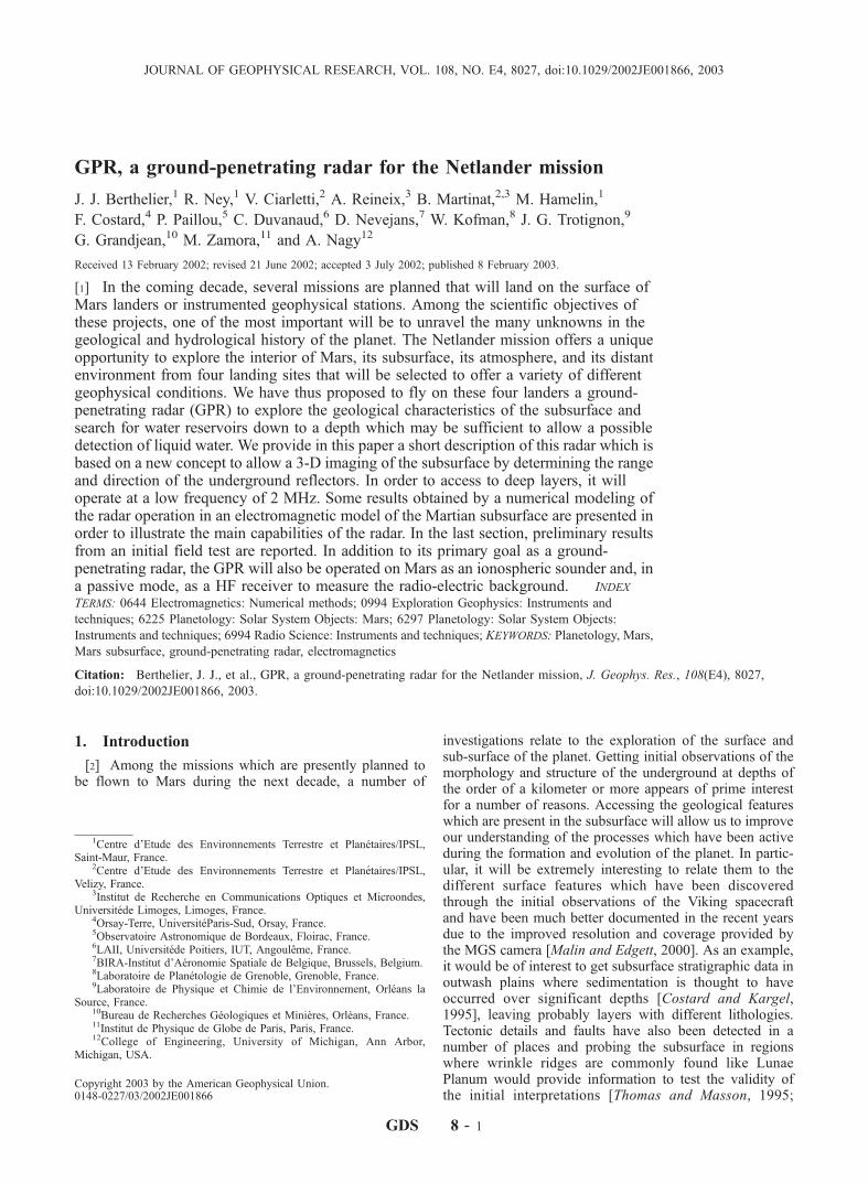
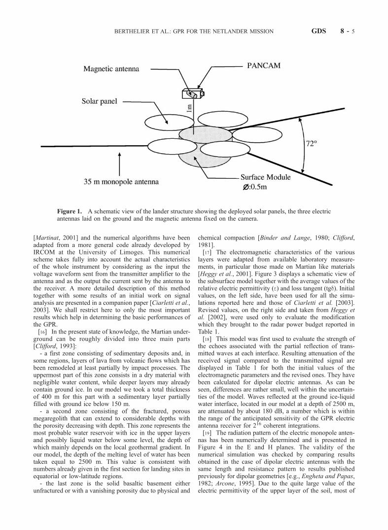
of the propagation vectors of returning waves is easier forsimple wave fields with discrete waves that are planepolarized and in such a case it can be performed even witha reduced number of electric or magnetic components. Weare well aware that the reflection processes on the interfacesor on discrete reflectors such as boulders may well disturbthe polarization of the reflected waves [Ulaby et al., 1986;Ogilvy, 1991] but, nevertheless, it is evidently of interest toprovide the radar with the capability to transmit planepolarized waves. In addition, being able to transmit linearlypolarized waves and vary their polarization will also bringobservations of significant interest since the characteristicsof the reflected waves are related to the physical andelectromagnetic properties of the reflectors. They can alsobe used to discriminate between various reflectors anddetect a specific signature linked to the presence of water.To this aim, a set of three electric antennas with length of 35m, stored in their deployment device on the flank of thelander body, will be deployed and laid on the ground in asymmetrical pattern dictated by the geometry of the 5 solarpanels of the lander (Figure 1). There is one central antennaand two others at an angle of 144� on each side of the firstone. As will be shown in section 4, applying variable phaseshifts between the signals fed to the 3 antennas also allowsus to modify the global radiation pattern of the electricantennas. Energy can thus be radiated in various directions,resulting in a beam steering capability for the GPR. Theantennas are broadband resistively damped quarter-wavemonopoles [Wu and King, 1965] similar to those widelyused in high-frequency impulse radars [Kanda, 1978;Degauque and Thery, 1986]. At the expense of some lossof efficiency, the damped monopoles reduce the ringingeffects detrimental to observations at short distances. Theelectric antennas will be made of thin Kapton ribbons with avariable resistive metallic layer deposited under vacuum. Inorder to simplify the electronics and also to save power,only a single antenna will be powered at a time during anelementary mode of operation. The others will be switchedon in sequence during the 2 following modes in order tohave a complete pattern of transmitted polarization. Allprocesses involved in the underground propagation andreflection processes are linear and the electronic circuitswill be carefully set-up to provide the required linearity.Under such conditions, signal synthesis of the data receivedon the Earth will allow us to reproduce transmitted waveswith variable polarization characteristics, in particular avertically propagating plane polarized wave.[12] Owing to the very tight constraints of mass which are
imposed on the Netlander mission, we have been led to useonly one magnetic antenna and to manage in such a waythat it can be positioned along three mutually orthogonal
directions. This is achieved by installing this antenna on thePANCAM camera which is located at the end of a 1 m longvertically deployed boom and can be rotated over a com-plete 360� to have a complete viewing of the landscape. Theantenna is mounted at 54.7� with respect to the vertical axisand for three azimuth angles of the camera evenly spaced by120�, the corresponding directions of the magnetic antennaare mutually orthogonal.[13] The electronics is entirely located inside the lander
and, as evidenced by the block diagram displayed in Figure2, consists in two main parts, respectively the digital andanalog circuits. The digital part is organized around anFPGA which (i) drives a Direct Digital Synthesis (DDS)component used to generate the waveform to be transmittedand (ii) ensures the sampling and analog to digital con-version of the received signals. Among others, this numeri-cally controlled transmission technique provides two majoradvantages. It offers first a very convenient and versatileway to select the desired frequencies and waveforms of thetransmitted signals. In addition, it allows us to sample thereceived signal at times corresponding to perfectly fixedphase lags compared to the transmitted signal, a propertywhich is essential for measurements which require coherentintegration over very long times. The analog circuits are thetransmitter filters and amplifiers, the variable gain receiverand the various switches. The transmitter amplifier deliversa nominal power of 10 W to the antenna. The sensitivity ofthe electric antennas and their receiver is presently esti-mated to be better than 5 nV/(Hz)1/2 for a 3.104 K galacticnoise temperature and the measured sensitivity of themagnetic antenna is �5.10�15 T/(Hz)1/2.[14] We plan to use bi-phase transmission with alternate
opposite polarities and have two different types of pulses:short 1 ms pulses, for short range measurements, and long10 ms BPSK coded pulses for deep sounding. In additioncoherent integration will be performed directly in the GPRelectronics by the FPGA. It has been shown previously[Berthelier et al., 2000] that the sensitivity required to detectthe liquid water interface at 2500 m, as modeled in numericalsimulations presented in the next section, calls for a max-imum of 216 coherent additions for the electric antennas and224 for the magnetic antennas owing to their intrinsic lowersensitivity. The GPR will be operated in several differentoperational modes dedicated to the specific scientific objec-tives. These will be the ‘‘ground-penetrating radar’’ modeproper to investigate the subsurface, the ‘‘ionospheric’’mode to probe the lower ionosphere, the ‘‘radio-electricbackground’’ mode to study electrical discharges in theatmosphere and perform ionospheric absorption measure-ments, and the ‘‘permittivity probe’’ mode to determine thepermittivity of the superficial soil.
4. Summary of Results from a NumericalSimulation
[15] In order to evaluate the GPR performances a con-siderable effort has been devoted to the numerical simula-tion of its operation. To this aim we have built a simplemodel of the electromagnetic characteristics of the Martiansubsurface which reproduces the main features that areexpected by Martian geologists. An FDTD method hasbeen used to describe the wave propagation and diffusion
GDS 8 - 4 BERTHELIER ET AL.: GPR FOR THE NETLANDER MISSION
[Martinat, 2001] and the numerical algorithms have beenadapted from a more general code already developed byIRCOM at the University of Limoges. This numericalscheme takes fully into account the actual characteristicsof the whole instrument by considering as the input thevoltage waveform sent from the transmitter amplifier to theantenna and as the output the current sent by the antenna tothe receiver. A more detailed description of this methodtogether with some results of an initial work on signalanalysis are presented in a companion paper [Ciarletti et al.,2003]. We shall restrict here to only the most importantresults which help in determining the basic performances ofthe GPR.[16] In the present state of knowledge, the Martian under-
ground can be roughly divided into three main parts[Clifford, 1993]:- a first zone consisting of sedimentary deposits and, in
some regions, layers of lava from volcanic flows which hasbeen remodeled at least partially by impact processes. Theuppermost part of this zone consists in a dry material withnegligible water content, while deeper layers may alreadycontain ground ice. In our model we took a total thicknessof 400 m for this part with a sedimentary layer partiallyfilled with ground ice below 150 m.- a second zone consisting of the fractured, porous
megaregolith that can extend to considerable depths withthe porosity decreasing with depth. This zone represents themost probable water reservoir with ice in the upper layersand possibly liquid water below some level, the depth ofwhich mainly depends on the local geothermal gradient. Inour model, the depth of the melting level of water has beentaken equal to 2500 m. This value is consistent withnumbers already given in the first section for landing sites inequatorial or low-latitude regions.- the last zone is the solid basaltic basement either
unfractured or with a vanishing porosity due to physical and
chemical compaction [Binder and Lange, 1980; Clifford,1981].[17] The electromagnetic characteristics of the various
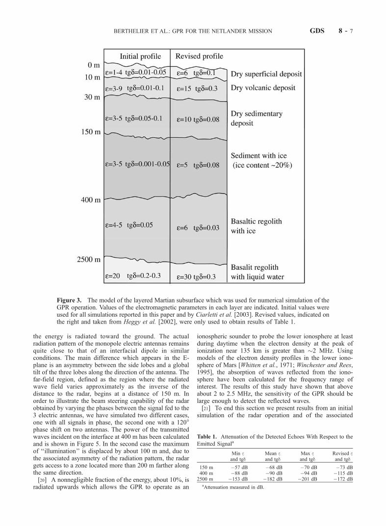
layers were adapted from available laboratory measure-ments, in particular those made on Martian like materials[Heggy et al., 2001]. Figure 3 displays a schematic view ofthe subsurface model together with the average values of therelative electric permittivity (e) and loss tangent (tgd). Initialvalues, on the left side, have been used for all the simu-lations reported here and those of Ciarletti et al. [2003].Revised values, on the right side and taken from Heggy etal. [2002], were used only to evaluate the modificationwhich they brought to the radar power budget reported inTable 1.[18] This model was first used to evaluate the strength of
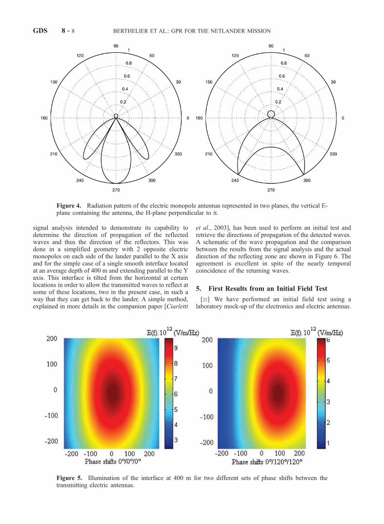
the echoes associated with the partial reflection of trans-mitted waves at each interface. Resulting attenuation of thereceived signal compared to the transmitted signal aredisplayed in Table 1 for both the initial values of theelectromagnetic parameters and the revised ones. They havebeen calculated for dipolar electric antennas. As can beseen, differences are rather small, well within the uncertain-ties of the model. Waves reflected at the ground ice-liquidwater interface, located in our model at a depth of 2500 m,are attenuated by about 180 dB, a number which is withinthe range of the anticipated sensitivity of the GPR electricantenna receiver for 216 coherent integrations.[19] The radiation pattern of the electric monopole anten-
nas has been numerically determined and is presented inFigure 4 in the E and H planes. The validity of thenumerical simulation was checked by comparing resultsobtained in the case of dipolar electric antennas with thesame length and resistance pattern to results publishedpreviously for dipolar geometries [e.g., Engheta and Papas,1982; Arcone, 1995]. Due to the quite large value of theelectric permittivity of the upper layer of the soil, most of
Figure 1. A schematic view of the lander structure showing the deployed solar panels, the three electricantennas laid on the ground and the magnetic antenna fixed on the camera.
BERTHELIER ET AL.: GPR FOR THE NETLANDER MISSION GDS 8 - 5
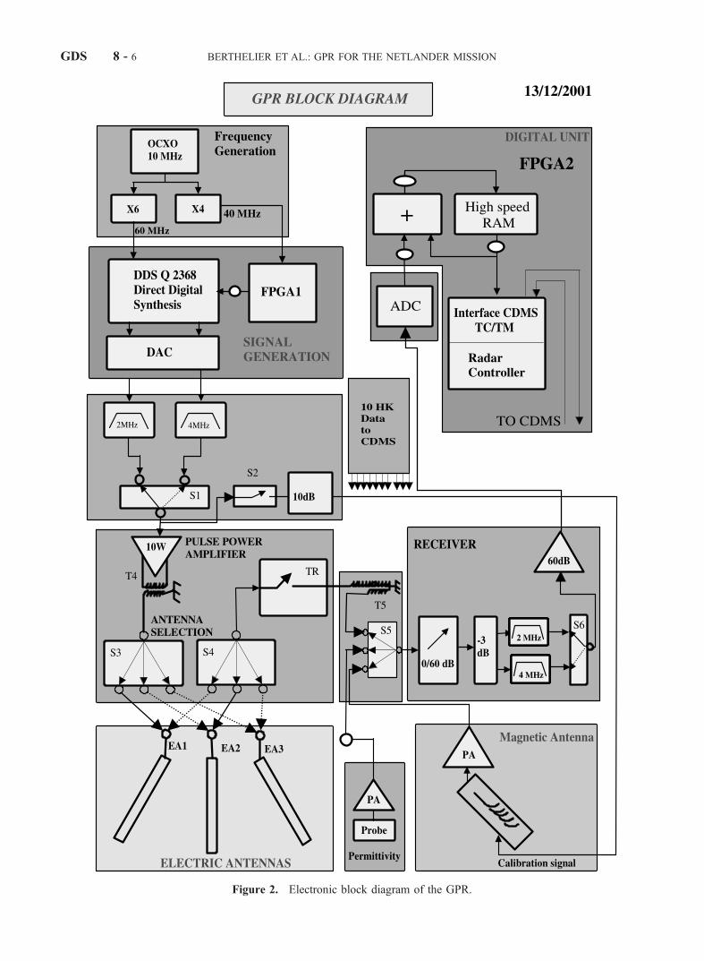
Figure 2. Electronic block diagram of the GPR.
GDS 8 - 6 BERTHELIER ET AL.: GPR FOR THE NETLANDER MISSION
the energy is radiated toward the ground. The actualradiation pattern of the monopole electric antennas remainsquite close to that of an interfacial dipole in similarconditions. The main difference which appears in the E-plane is an asymmetry between the side lobes and a globaltilt of the three lobes along the direction of the antenna. Thefar-field region, defined as the region where the radiatedwave field varies approximately as the inverse of thedistance to the radar, begins at a distance of 150 m. Inorder to illustrate the beam steering capability of the radarobtained by varying the phases between the signal fed to the3 electric antennas, we have simulated two different cases,one with all signals in phase, the second one with a 120�phase shift on two antennas. The power of the transmittedwaves incident on the interface at 400 m has been calculatedand is shown in Figure 5. In the second case the maximumof ‘‘illumination’’ is displaced by about 100 m and, due tothe associated asymmetry of the radiation pattern, the radargets access to a zone located more than 200 m farther alongthe same direction.[20] A nonnegligible fraction of the energy, about 10%, is
radiated upwards which allows the GPR to operate as an
ionospheric sounder to probe the lower ionosphere at leastduring daytime when the electron density at the peak ofionization near 135 km is greater than �2 MHz. Usingmodels of the electron density profiles in the lower iono-sphere of Mars [Whitten et al., 1971; Winchester and Rees,1995], the absorption of waves reflected from the iono-sphere have been calculated for the frequency range ofinterest. The results of this study have shown that aboveabout 2 to 2.5 MHz, the sensitivity of the GPR should belarge enough to detect the reflected waves.[21] To end this section we present results from an initial
simulation of the radar operation and of the associated
Figure 3. The model of the layered Martian subsurface which was used for numerical simulation of theGPR operation. Values of the electromagnetic parameters in each layer are indicated. Initial values wereused for all simulations reported in this paper and by Ciarletti et al. [2003]. Revised values, indicated onthe right and taken from Heggy et al. [2002], were only used to obtain results of Table 1.
Table 1. Attenuation of the Detected Echoes With Respect to the
Emitted Signala
Min eand tgd
Mean eand tgd
Max eand tgd
Revised eand tgd
150 m �57 dB �68 dB �70 dB �73 dB400 m �88 dB �90 dB �94 dB �115 dB2500 m �153 dB �182 dB �201 dB �172 dB
aAttenuation measured in dB.
BERTHELIER ET AL.: GPR FOR THE NETLANDER MISSION GDS 8 - 7
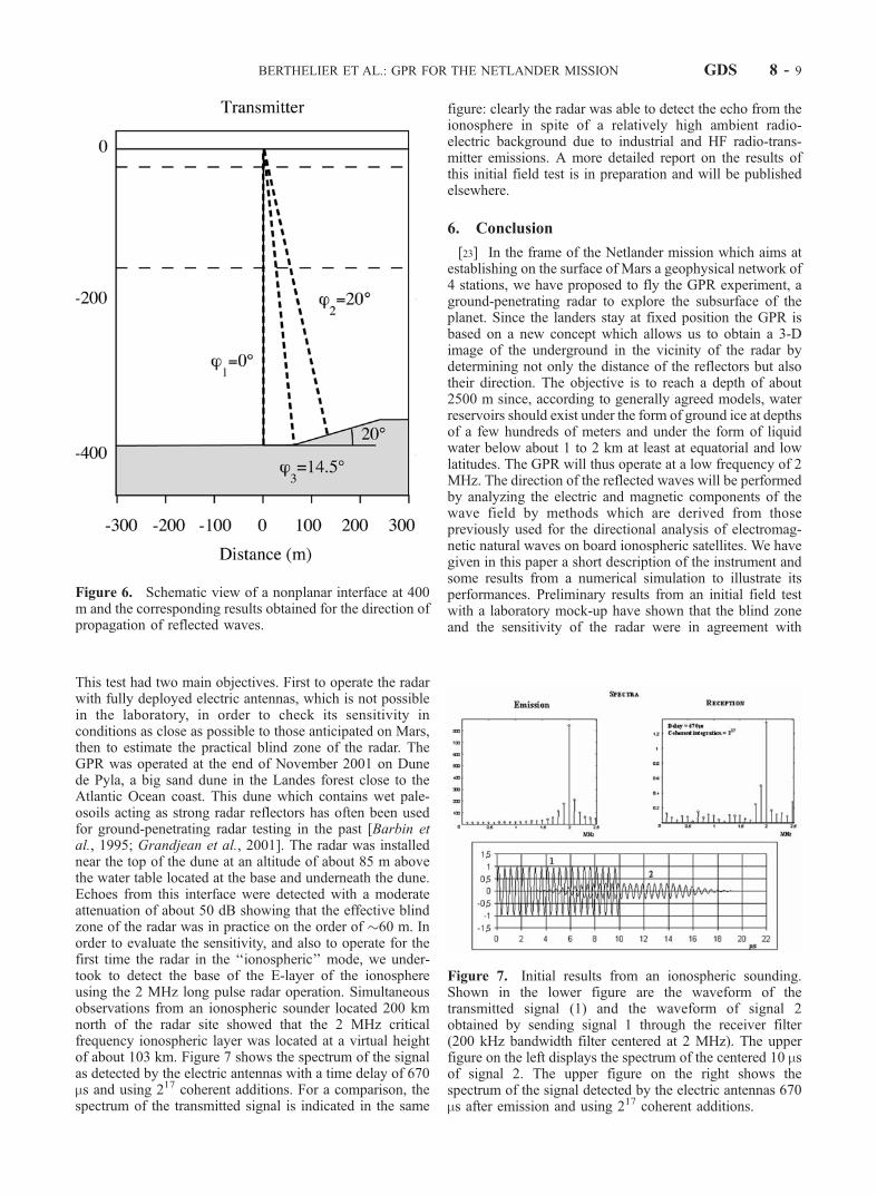
signal analysis intended to demonstrate its capability todetermine the direction of propagation of the reflectedwaves and thus the direction of the reflectors. This wasdone in a simplified geometry with 2 opposite electricmonopoles on each side of the lander parallel to the X axisand for the simple case of a single smooth interface locatedat an average depth of 400 m and extending parallel to the Yaxis. This interface is tilted from the horizontal at certainlocations in order to allow the transmitted waves to reflect atsome of these locations, two in the present case, in such away that they can get back to the lander. A simple method,explained in more details in the companion paper [Ciarletti
et al., 2003], has been used to perform an initial test andretrieve the directions of propagation of the detected waves.A schematic of the wave propagation and the comparisonbetween the results from the signal analysis and the actualdirection of the reflecting zone are shown in Figure 6. Theagreement is excellent in spite of the nearly temporalcoincidence of the returning waves.
5. First Results from an Initial Field Test
[22] We have performed an initial field test using alaboratory mock-up of the electronics and electric antennas.
Figure 4. Radiation pattern of the electric monopole antennas represented in two planes, the vertical E-plane containing the antenna, the H-plane perpendicular to it.
Figure 5. Illumination of the interface at 400 m for two different sets of phase shifts between thetransmitting electric antennas.
GDS 8 - 8 BERTHELIER ET AL.: GPR FOR THE NETLANDER MISSION
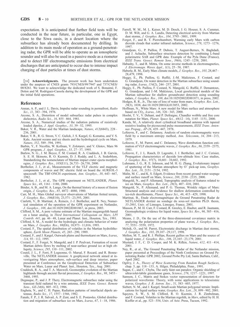
This test had two main objectives. First to operate the radarwith fully deployed electric antennas, which is not possiblein the laboratory, in order to check its sensitivity inconditions as close as possible to those anticipated on Mars,then to estimate the practical blind zone of the radar. TheGPR was operated at the end of November 2001 on Dunede Pyla, a big sand dune in the Landes forest close to theAtlantic Ocean coast. This dune which contains wet pale-osoils acting as strong radar reflectors has often been usedfor ground-penetrating radar testing in the past [Barbin etal., 1995; Grandjean et al., 2001]. The radar was installednear the top of the dune at an altitude of about 85 m abovethe water table located at the base and underneath the dune.Echoes from this interface were detected with a moderateattenuation of about 50 dB showing that the effective blindzone of the radar was in practice on the order of �60 m. Inorder to evaluate the sensitivity, and also to operate for thefirst time the radar in the ‘‘ionospheric’’ mode, we under-took to detect the base of the E-layer of the ionosphereusing the 2 MHz long pulse radar operation. Simultaneousobservations from an ionospheric sounder located 200 kmnorth of the radar site showed that the 2 MHz criticalfrequency ionospheric layer was located at a virtual heightof about 103 km. Figure 7 shows the spectrum of the signalas detected by the electric antennas with a time delay of 670ms and using 217 coherent additions. For a comparison, thespectrum of the transmitted signal is indicated in the same
figure: clearly the radar was able to detect the echo from theionosphere in spite of a relatively high ambient radio-electric background due to industrial and HF radio-trans-mitter emissions. A more detailed report on the results ofthis initial field test is in preparation and will be publishedelsewhere.
6. Conclusion
[23] In the frame of the Netlander mission which aims atestablishing on the surface of Mars a geophysical network of4 stations, we have proposed to fly the GPR experiment, aground-penetrating radar to explore the subsurface of theplanet. Since the landers stay at fixed position the GPR isbased on a new concept which allows us to obtain a 3-Dimage of the underground in the vicinity of the radar bydetermining not only the distance of the reflectors but alsotheir direction. The objective is to reach a depth of about2500 m since, according to generally agreed models, waterreservoirs should exist under the form of ground ice at depthsof a few hundreds of meters and under the form of liquidwater below about 1 to 2 km at least at equatorial and lowlatitudes. The GPR will thus operate at a low frequency of 2MHz. The direction of the reflected waves will be performedby analyzing the electric and magnetic components of thewave field by methods which are derived from thosepreviously used for the directional analysis of electromag-netic natural waves on board ionospheric satellites. We havegiven in this paper a short description of the instrument andsome results from a numerical simulation to illustrate itsperformances. Preliminary results from an initial field testwith a laboratory mock-up have shown that the blind zoneand the sensitivity of the radar were in agreement with
Figure 6. Schematic view of a nonplanar interface at 400m and the corresponding results obtained for the direction ofpropagation of reflected waves.
Figure 7. Initial results from an ionospheric sounding.Shown in the lower figure are the waveform of thetransmitted signal (1) and the waveform of signal 2obtained by sending signal 1 through the receiver filter(200 kHz bandwidth filter centered at 2 MHz). The upperfigure on the left displays the spectrum of the centered 10 msof signal 2. The upper figure on the right shows thespectrum of the signal detected by the electric antennas 670ms after emission and using 217 coherent additions.
BERTHELIER ET AL.: GPR FOR THE NETLANDER MISSION GDS 8 - 9
expectation. It is anticipated that further field tests will beconducted in the near future, in particular, one in Egypt,close to the Siwa oasis, in a desert location where thesubsurface has already been documented by drilling. Inaddition to its main mode of operation as a ground-penetrat-ing radar, the GPR will be able to operate as an ionosphericsounder and will also be used in a passive mode as a riometerand to detect HF electromagnetic emissions from electricaldischarges that are anticipated to occur due to intense impactcharging of dust particles at times of dust storms.
[24] Acknowledgments. The present work has been undertakenunder the auspices of CNES grants 793/CNES/99/7947 and 737/CNES/00/8261. We want to acknowledge the dedicated work of S. Bonaime, F.Dolon and M. Rodriguez-Cassola during the development of the GPR andthe initial field operations.
ReferencesAnnan, A. P., and J. L. Davis, Impulse radar sounding in permafrost, RadioSci., 11, 383–394, 1976.
Arcone, S. A., Distortion of model subsurface radar pulses in complexdielectrics, Radio Sci., 16, 855–864, 1981.
Arcone, S. A., Numerical studies of the radiation patterns of resistivelyloaded dipoles, J. Appl. Geophys., 33, 39–52, 1995.
Baker, V. R., Water and the Martian landscape, Nature, 412(6843), 228–236, 2001.
Baker, V. R., R. G. Strom, V. C. Gulick, J. S. Kargel, G. Komatsu, and V. S.Kale, Ancient oceans and ice sheets and the hydrological cycle on Mars,Nature, 352, 589–594, 1991.
Barbin, Y., F. Nicollin, W. Kofman, V. Zolotarev, and V. Glotov, Mars 96GPR program, J. Appl. Geophys., 33, 27–37, 1995.
Barlow, N. G., J. M. Boyce, F. M. Costard, R. A. Craddock, J. B. Garvin,S. E. H. Skimoto, R. O. Kuzmin, D. J. Roddy, and L. A. Soderblom,Standardizing the nomenclature of Martian impact crater ejecta morphol-ogies, J. Geophys. Res., 105(E11), 26,733–26,738, 2000.
Berthelier, J. J., et al., Measurements of the VLF electric and magneticcomponents of waves and DC electric field on board the AUREOL-3spacecraft: The TBF-ONCH experiment, Ann. Geophys., 38, 643–667,1982.
Berthelier, J. J., et al., The GPR experiment on NETLANDER, Planet.Space Sci., 48, 1161–1180, 2000.
Binder, A. B., and M. A. Lange, On the thermal history of a moon of fissionorigin, J. Geophys. Res., 85, 4872–4880, 1980.
Carr, M. H., Mars Global surveyor observations of Martian fretted terrain,J. Geophys. Res., 106(E10), 23,571–23,593, 2001.
Ciarletti, V., B. Martinat, A. Reineix, J.-J. Berthelier, and R. Ney, Numer-ical simulation of the operation of the GPR experiment on Netlander,J. Geophys., 108, doi:10.1029/2002JE001867, in press, 2003.
Clifford, S. M., A pore volume estimate of the Martian megaregolith basedon a lunar analog, in Third International Colloquium on Mars, LPIContrib. 441, pp. 46–48, Lunar and Planet. Inst., Houston, Tex., 1981.
Clifford, S. M., A model for the hydrologic and climatic behavior of wateron Mars, J. Geophys. Res., 98(E6), 10,973–11,016, 1993.
Costard, F., The spatial distribution of volatiles in the Martian hydrolitho-sphere, Earth Moon Planets, 45, 265–290, 1989.
Costard, F., and J. Kargel, Outwash plains and thermokarst on Mars, Icarus,114, 93–112, 1995.
Costard, F., F. Forget, N. Mangold, and J. P. Peulvast, Formation of recentMartian debris flows by melting of near-surface ground ice at high ob-liquity, Science, 295, 110–111, 2002.
Counil, J. L., F. Ferri, P. Lognonne, O. Marsal, F. Rocard, and R. Bonne-ville, The NETLANDER mission: A geophysical network aimed at in-vestigating Mars atmosphere, sub-surface and deep interior, paperpresented at Conference on the Geophysical Detection of SubsurfaceWater on Mars, Lunar and Planet. Inst., Houston, Tex., Aug. 2001.
Craddock, R. A., and T. A. Maxwell, Geomorphic evolution of the Martianhighlands through ancient fluvial processes, J. Geophys. Res., 98, 3453–3468, 1993.
Degauque, P., and J. P. Thery, Electromagnetic subsurface radar using thetransient field radiated by a wire antenna, IEEE Trans. Geosci. RemoteSens., GE-24(6), 805–812, 1986.
Engheta, N., and C. H. Papas, Radiation patterns of interfacial dipole an-tennas, Radio Sci., 17, 1557–1566, 1982.
Fanale, F. P., J. R. Salvail, A. P. Zent, and S. E. Postawko, Global distribu-tion and migration of subsurface ice on Mars, Icarus, 67, 1–18, 1986.
Farrell, W. M., M. L. Kaiser, M. D. Desch, J. G. Houser, S. A. Cummer,D. M. Wilt, and G. A. Landis, Detecting electrical activity from Martiandust storms, J. Geophys. Res., 104, 3795–3801, 1999.
Forget, F., and R. T. Pierrehumbert, Warming early Mars with carbondioxide clouds that scatter infrared radiation, Science, 278, 1273–1276,1997.
Grandjean, G., P. Paillou, P. Dubois, T. August-Bernex, N. Baghdadi,and J. Achache, Subsurface structures detection by combining L-bandpolarimetric SAR and GPR data: Example of the Pyla Dune (France),IEEE Trans. Geosci. Remote Sens., 39(6), 1245–1258, 2001.
Habashy, T., and R. Mittra, On some inverse methods in electromagnetics,J. Electromagn. Waves Appl., 1(1), 25–58, 1987.
Haberle, R. M., Early Mars climate models, J. Geophys. Res., 103, 28,467–28,479, 1998.
Heggy, E., Ph. Paillou, G. Ruffie, J.-M. Malezieux, F. Costard, andG. Grandjean, On water detection in the Martian subsurface using sound-ing radar, Icarus, 154(2), 244–257, 2001.
Heggy, E., Ph. Paillou, F. Costard, N. Mangold, G. Ruffie, F. Demantoux,G. Grandjean, and J.-M. Malezieux, Local geoelectrical models of theMartian subsurface for shallow groundwater detection using soundingradars, J. Geophys. Res., 108, doi:10.10292002JE001871, in press, 2002.
Hodges, R. R., Jr., The rate of loss of water from mars, Geophys. Res. Lett.,29(3), 1038, doi:10.1029/2001GL013853, 2002.
Hoffman, N., White Mars: A new model for Mars surface and atmospherebased on CO2, Icarus, 146, 326–343, 2000.
Hoolst, T. V., V. Dehant, and P. Defraigne, Chandler wobble and free corenutation for Mars, Planet. Space Sci., 48(12–14), 1145–1151, 2000.
Kanda, M., A relatively short cylindrical broadband antenna with taperedresistive loading for picosecond pulse measurements, IEEE Trans. Anten-nas Propag., AP-26, 439–447, 1978.
Lefeuvre, F., and C. Delannoy, Analysis of random electromagnetic wavefield by a maximum entropy method, Ann. Telecomm, 34, 204–213,1979.
Lefeuvre, F., M. Parrot, and C. Delannoy, Wave distribution function esti-mation of VLF electromagnetic waves, J. Geophys. Res., 86, 2359–2375,1981.
Lefeuvre, F., J. L. Rauch, D. Lagoutte, J. J. Berthelier, and J. C. Cerisier,Propagation characteristics of dayside low-altitude hiss: Case studies,J. Geophys. Res., 97(7), 10,601–10,602, 1992.
Luhmann, J. G., R. E. Johnson, and M. H. G. Zhang, Evolutionary impactof sputtering of the Martian atmosphere by O+ pick-up ions, Geophys.Res. Lett., 19, 2151–2154, 1992.
Malin, M. C., and K. S. Edgett, Evidence from recent ground water seepageand surface runoff on Mars, Science, 288, 2330–2335, 2000.
Mangold, N., and P. Allemand, Topographic analysis of features related toice on Mars, Geophys. Res. Lett., 28(3), 407–410, 2001.
Mangold, N., P. Allemand, and P. G. Thomas, Wrinkle ridges of Mars:Structural analysis and evidence for shallow deformation controlled byice-rich decollements, Planet. Space Sci., 46, 415–429, 1998.
Martinat, B., Etude electromagnetique du Ground Penatrating Radar deNETLANDER destine au sondage du sous-sol martien Ph.D. thesis,35-2001, Univ. of Limoges, Limoges, France, 2001.
Masson, P., M. H. Carr, F. Costard, R. Greeley, E. Hauber, and R. Jaumann,Geomophologic evidence for liquid water, Space Sci. Rev., 96, 385–416,2001.
Means, J. D., On the use of the three-dimensional covariance matrix inanalyzing the polarization properties of plane waves, J. Geophys. Res.,77, 5551–5559, 1972.
Melnik, O., and M. Parrot, Electrostatic discharge in Martian dust storms,J. Geophys. Res., 103, 29,107–29,117, 1998.
Mellon, M. T., and R. J. Phillips, Recent gullies on Mars and the source ofliquid water, J. Geophys. Res., 106, 23,165–23,179, 2001.
Mustard, J. F., C. D. Cooper, and M. K. Rifkin, Nature, 412, 411–414,2001.
Ney, R., et al., The Ground Penetrating Radar of the Netlander mission,paper presented at Proceedings of the Ninth Conference on Ground Pe-netrating Radar: GPR 2002, Ground Probe Pty Ltd, Santa Barbara, Calif.,April 2002.
Ogilvy, J. A., Theory of Wave Scattering From Random Rough Surfaces,chap. 5, pp. 118–133, A. Hilger, Philadelphia, Penn., 1991.
Sagan, C., and C. Chyba, The early faint sun paradox: Organic shielding ofultraviolet-labile greenhouse gases, Science, 276, 1217–1221, 1997.
Samson, J. C., Matrix and Stokes vector representation of detectors forpolarized waveforms: Theory, with some applications to teleseismicwaves, Geophys. J. R. Astron. Soc., 51, 583–603, 1977.
Siebert, N. M., and J. Kargel, Small-scale Martian polygonal terrain: Impli-cations for liquid surface water, Geophys. Res. Lett., 28, 899–902, 2001.
Squyres, S. W., S. M. Clifford, R. O. Kuzmin, J. R. Zimbelman,and F. Costard, Volatiles in the Martian regolith, in Mars, edited by H. H.Kieffer et al., pp. 523–554, Univ. of Ariz. Press, Tucson, 1992.
GDS 8 - 10 BERTHELIER ET AL.: GPR FOR THE NETLANDER MISSION
Thomas, P. G., and P. L. Masson, Martian fluidized crater distribution:Tectonic implications, Earth Moon Planets, 34, 169–176, 1995.
Ulaby, F. T., R. K.Moore, andA.K. Fung, Activemicrowave sensing of land,inMicrowave Remote Sensing, vol. III,From Theory to Applications, chap.21, pp. 1826–1827, Addison-Wesley-Longman, Reading, Mass., 1986.
Whitten, R. C., I. G. Popoff, and J. S. Sims, The ionosphere of Mars below80 km altitude, Planet. Space Sci., 19, 243–250, 1971.
Winchester, C., and D. Rees, Numerical models of the Martian coupledthermosphere and ionosphere, Adv. Space Res., 15(4), 51–68, 1995.
Wright, D. L., S. M. Hodge, J. A. Bradley, T. P. Grover, and R. W. Jacobel,A digital low-frequency, surface-profiling ice-radar system, J. Glaciol.,36(122), 112–121, 1990.
Wu, T. T., and R. W. P. King, The cylindrical antenna with non-reflectingresistive loading, IEEE Trans. Antennas Propag., AP-13(3), 369–373,1965.
�����������������������J. J. Berthelier, M. Hamelin, and R. Ney, Centre d’Etude des Environne-
ments Terrestre et Planetaires/IPSL, 4 Avenue deNeptune, 94107 Saint-MaurCedex, France. ([email protected])V. Ciarletti and B.Martinat, CETP/IPSL, 10/12Avenue de l’Europe, 78140
Velizy, France. ([email protected])
F. Costard, UMR 8616, Orsay-Terre, Universite Paris-Sud, 91405 OrsayCedex, France.C. Duvanaud, LAII, Universite de Poitiers, IUT, 4 Avenue de Varsovie,
16021 Angouleme Cedex, France.G. Grandjean, Bureau de Recherches Geologiques et Minieres, BP 6009
45060, Orleans, France.W. Kofman, Laboratoire de Planetologie de Grenoble, Batiment D de la
Physique, BP 53, 38041 Grenoble Cedex 09, France.A. Nagy, College of Engineering, University of Michigan, Ann Arbor,
MI 48109-2143, USA.D. Nevejans, BIRA-Institut d’Aeronomie Spatiale de Belgique, Ringlaan
3, B-1180 Brussels, Belgium.P. Paillou,ObservatoireAstronomique deBordeaux, BP 89, 33270Floirac,
France.A. Reineix, Institut de Recherche en Communications Optiques et
Microondes, Universite de Limoges, 123 Avenue Albert Thomas, 87060Limoges Cedex, France.J. G. Trotignon, Laboratoire de Physique et Chimie de l’Environne-
ment, 3 Avenue de la Recherche Scientifique, 45100 Orleans la Source,France.M. Zamora, Institut de Physique de Globe de Paris, 4 place Jussieu,
75005 Paris, France.
BERTHELIER ET AL.: GPR FOR THE NETLANDER MISSION GDS 8 - 11