Embed Size (px)
Citation preview

Fathi Shaqour Ground anchors in an aggressivehydro-environment
Received: 2 December 2004Accepted: 26 June 2005Published online: 10 November 2005� Springer-Verlag 2005
Abstract Kuwait City is a MiddleEastern coastal city characterized byarid conditions with shallow, salinegroundwater. As some parts of thenew ring road development werebelow the ground water level, 5,000anchors were incorporated in thedesign to restrain the road againsthydrostatic uplift pressures. About750 anchors were only partiallycompleted when they were inun-dated with aggressive groundwaterfor a period of about 2 years whendewatering was temporarily aban-doned as a result of the Gulf War in1990. Subsequently, physical, met-allurgical and strength tests wereundertaken to assess both the degreeof corrosion and the long-termintegrity of these partially completedanchors. The paper discusses thetesting, the remedial measures andthe long-term monitoring system. Itwas decided to keep some of thedewatering wells as a precautionarystandby in case of future problems.
Keywords Saline groundwater ÆHydrostatic uplift pressure ÆGround anchors Æ Corrosion ÆKuwait
Resume La ville de Koweıt est uneville cotiere du Moyen-Orient cara-
cterisee par des conditions aridesavec des eaux souterraines salees peuprofondes. Comme certaines partiesde la nouvelle rocade en cours deconstruction se trouvaient sous leniveau de la nappe phreatique, 5000tirants d’ancrage ont ete integresdans les structures pour compenserle soulevement hydrostatique. Envi-ron 750 tirants venaient d’etre par-tiellement realises lorsque le site futennoye par des eaux agressives pen-dant deux ans, du fait de l’abandontemporaire des rabattements enconsequence de la guerre du Golfeen 1990. Par la suite, des essais decaracterisation physique, metallur-gique et de resistance mecanique ontete realises pour evaluer a la fois ledegre de corrosion et la tenue a longterme de ces premiers ancrages in-stalles. L’article presente les essais decontrole, les mesures compensatriceset le systeme de surveillance a longterme. Il a ete decide de conservercertains des puits de rabattement ensituation provisoire en cas de prob-lemes futurs.
Mots cles Nappe phreatiquesalee Æ Poussee hydrostatique ÆTirants d’ancrage Æ Corrosion ÆKoweıt
Bull Eng Geol Env (2006) 65: 43–56DOI 10.1007/s10064-005-0011-4 ORIGINAL PAPER
F. Shaqour (&)Department of Applied Geology andEnvironment, The University of Jordan,P.O. Box 1278 11953 Tla El-Ali, Amman,JordanE-mail: [email protected]

Introduction
The present study discusses the unique case of an engi-neering structure that suffered corrosion attack as a re-sult of a hydro-political environment caused by the GulfWar. The state of Kuwait is located on the northwesterncoast of the Arabian Gulf. A part of the Arabian Desert,it is bordered by Saudi Arabia on the south and west andIraq on the north (Fig. 1). The city of Kuwait has sev-eral ring roads with radial intersecting streets leadingtowards the city centre (Fig. 2). The first ring roadpasses under three intersections where the road pave-ment is a few metres below the groundwater table. As aconsequence, the construction of the road involved theinstallation of ground anchors in the lower areas tocounteract the hydrostatic (uplift) pressures.
To allow construction works in a dry environment, adewatering system of deep wells was designed andoperated to lower the groundwater table. Due to thehigh salinity of the groundwater, the anchors were de-
signed to meet the marine double protection criteria asidentified by the British Standard 8081:1989. This is toavoid corrosion by aggressive groundwater, which isknown to be rich in chlorides, nitrates and sulphates.Figure 3 shows the locations of the ground anchors atthe three main intersections on the first ring road.
The invasion of Kuwait took place during the exe-cution of the project and a total of 750 anchors werepartially completed when the dewatering was stoppedwhereby the water table rose back to its original posi-tion, inundating both the troughs and the anchors. Thepaper discusses the damage assessment and the testingprogramme carried out when the construction workswere re-commenced.
Physiography and general geology of the study area
The area is characterized by an arid climate with diurnaland annual temperature variations. In summer the
Fig. 1 Location of Kuwait city
44 Fathi Shaqour

temperature ranges generally between 25 and 45�C butcould reach a high of 53�C, while in winter the range isgenerally between 3 and 15�C although extremes of)3�C may be reached during the night (Al-Kulaib 1984).
Precipitation is usually very low and rarely exceeds100 mm per year with temporal and spatial variations inintensity and duration. The evaporation potential isextremely high and amounts to 3000 mm per year (Al-Kulaib 1984). Groundwater is shallow and ranges indepth between a few decimetres to a few metres from theground surface.
The topography is generally flat with scattered lowhills, shallow depressions and low escarpments. Davies(1965) and Milton (1967) consider these to be related toerosion while Higginbotttom (1954) and Fuchs et al.(1968) consider them to be of structural and tectonicorigin. Between the escarpments, sand sheets and dunesof up to 50 m in height are common over most of the
State. In addition, there are flat, low coastal and inlandsalt crusted areas known as sabkhas and salinas,respectively (Shaqour 1990).
Both uncemented and cemented soil (calcrete, locallyknown as gatch) are present and can normally supportshallow foundations. Both are used as compacted fillmaterial.
The geology of Kuwait is mainly sandstone andcarbonate formations overlying the Arabian shieldbasement of Pre-Cambrian igneous and metamorphicrocks (Mitchel 1957). The oldest outcrops in Kuwait arecarbonate deposits, which formed the last shallowmarine environment during the Eocene (Parsons Cor-poration 1963). These deposits are unconformablyoverlain by a sequence of terriginous sediments rangingfrom Miocene to Recent in age (Burdon and Al-Sharhan1968). The geology is shown in Figs. 4 and 5 and can besummarised as follows:
Fig. 2 Motorway map of Kuwait showing the location of the first ring road project
Ground anchors in an aggressive hydro-environment 45

Fig. 3 Location of ground anchors at three main intersections of the first ring road (dots represent positions of anchors, heavy dotsanchors being monitored)
46 Fathi Shaqour
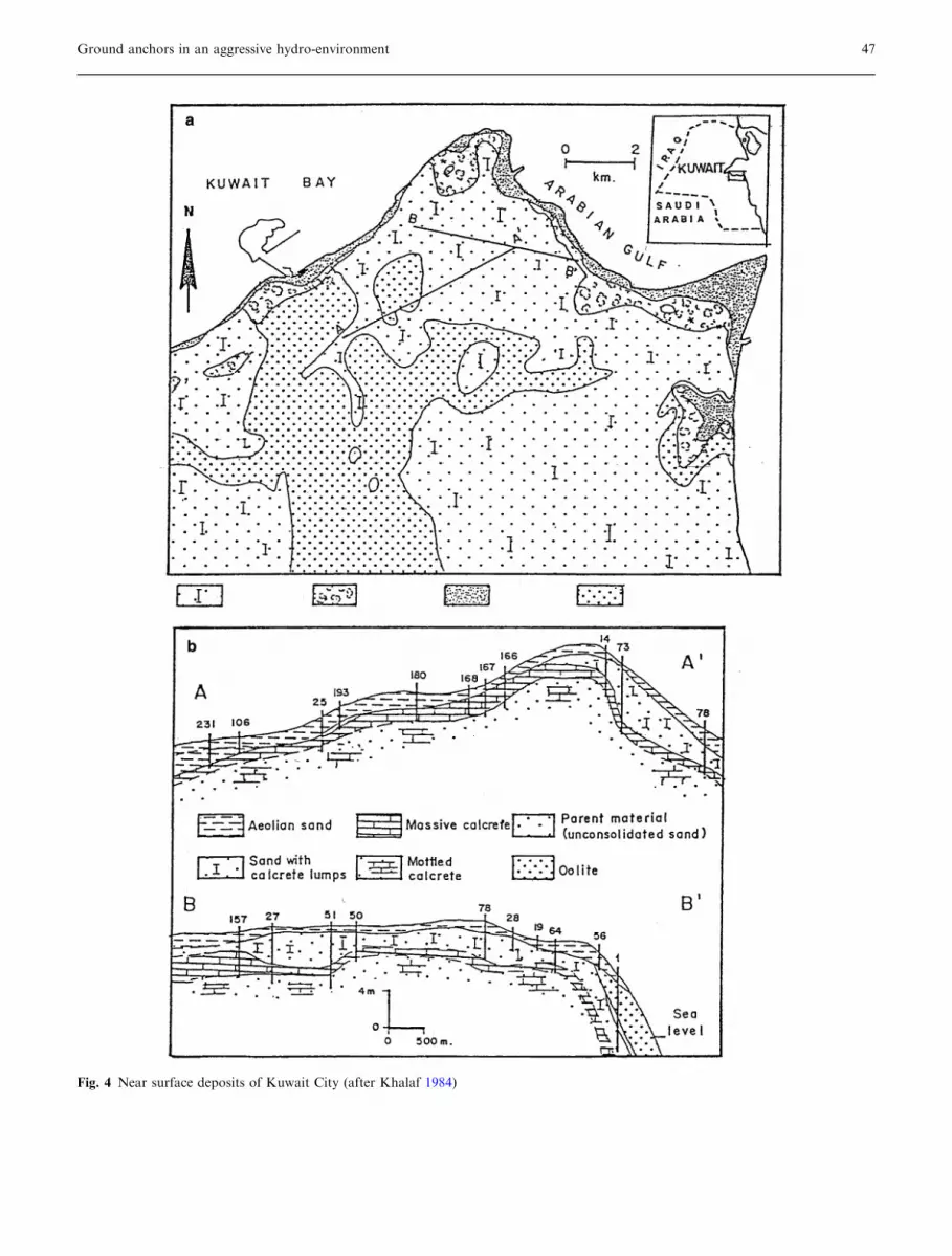
Fig. 4 Near surface deposits of Kuwait City (after Khalaf 1984)
Ground anchors in an aggressive hydro-environment 47

Dammam formation
The deposits are mainly limestones of Eocene age (Up-per Hasa Group) which dip gently towards the north/north-east with some structural and erosional undula-tions (Parsons Corporation 1963). The upper part isgreyish, stratified and siliceous with irregular dark chertconcretions and nodules. Where exposed, the base is awhite and porous chalky limestone with casts of mol-luscs and various species of foraminifera (Fuchs et al.1968). From the late Eocene to the end of the Oligocene,the Dammam limestone was subjected to extensive ero-sion and karstification. There is a sharp unconformitybetween the Hasa Group and the overlying KuwaitGroup (Burdon and Al-Sharhan 1968) with some 3.5–10 m of residual soil at the top of the Dammam for-mation (Omar et al. 1981).
Kuwait group
These deposits are mainly sands and gravels with occa-sional evaporite phases of anhydrite and gypsum withclay intercalations, ranging in age from late Oligocene toPleistocene (Owen and Nasr 1958; Salman 1979). These
deposits are undifferentiated in the south of the Statewhile three formations are recognized in the north: theGhar formation consisting mainly of sands and gravelswith clay intercalations (Al-Hajji 1976); the lower Farsformation comprising anhydrite, gypsum, clays andintercalations of shallow water limestomes of the Mio-cene–Pliocene age; and the Dibdiba formation consistingof cross-bedded fluviatile sands and gravels locally ce-mented with carbonates or sulphates with intercalationsof sandy clays. This formation belongs to the Pluvialperiod of the Pleistocene (Fuchs et al. 1968).
Recent and sub-Recent deposits
These deposits form most of the surface cover of Kuwaitand can be sub-divided into six classes (Khalaf et al.1984):
(i) Aeolian deposits: sand sheets with flat surfaces, sanddunes of variable sizes, coastal dunes, drifts resultingfrom sand accumulation around shrubs and finallywadi fill materials.
(ii) Residual gravels and duricrusts: residual sheets orridges capping the remnants from erosion and
Fig. 5 Stratigraphic column of near surface deposits in the State of Kuwait (Salman 1979)
48 Fathi Shaqour

accumulating in wadis. Duricrusts occur as hardsurface deposits formed during secondary cementa-tion (gypcrete, dolcrete, calcrete and silcrete); cal-crete is dominant in Kuwait.
(iii) Playa deposits: depressed desert areas in which rainand sediments periodically collect.
(iv) Desert plain deposits: mainly of sand, silt and graveldeposited by wind and/or water.
(v) Slope deposits: rock debris at the foot of higherareas.
(vi) Coastal deposits: coastal calcrete, sabkha deposits(flat salt encrusted supratidal areas), beach depositsand coastal dune deposits.Figure 4 presents a nearsurface geological map of Kuwait City, while Fig. 5features a section that shows the stratigraphicalrelationships of the surface deposits in Kuwait.
Anchors: general background
Two types of anchors were used in the road stabilisationproject: mono-bar and strand anchors. The design ofthese is basically the same except that the 32 and 36 mmdiameter mono-bar anchors have a strong perlitic core
which gradually changes to a perlitic/ferritic structuretowards the edges, while in the case of the strand an-chors the structural element is formed of five strandseach consisting of seven high-carbon steel wires (com-plying with ASTM A416 Grade 270). The central ‘‘king’’wire is surrounded by six stranded wires. All wires arefactory mounted in PE sheathing.
The anchors are typically formed of a fixed end, freelength and head, all of which are waterproofed. In thefixed end, the bar or strands are embedded in a doublelayer of cement grout encased in corrugated PVC totransfer the load to the outer grout and soil. In the freelength, the strands are encased in polyethylene (PE)sheathing filled with grease within a smooth PVC pipe.The mono-bar is embedded in cement grout within aninner smooth PVC pipe which extends to the anchorhead. The inner PVC is surrounded by grease and cov-ered by an outer layer of grout and PVC. The purpose ofthe grease is to reduce friction in the free length. Fig-ure 6 provides a schematic diagram of the mono-bar (a)and strand (b) anchors.
Fig. 6 Schematic diagram showing typical design of: a mono-barand b strand anchor
Fig. 6 (Contd.)
Ground anchors in an aggressive hydro-environment 49
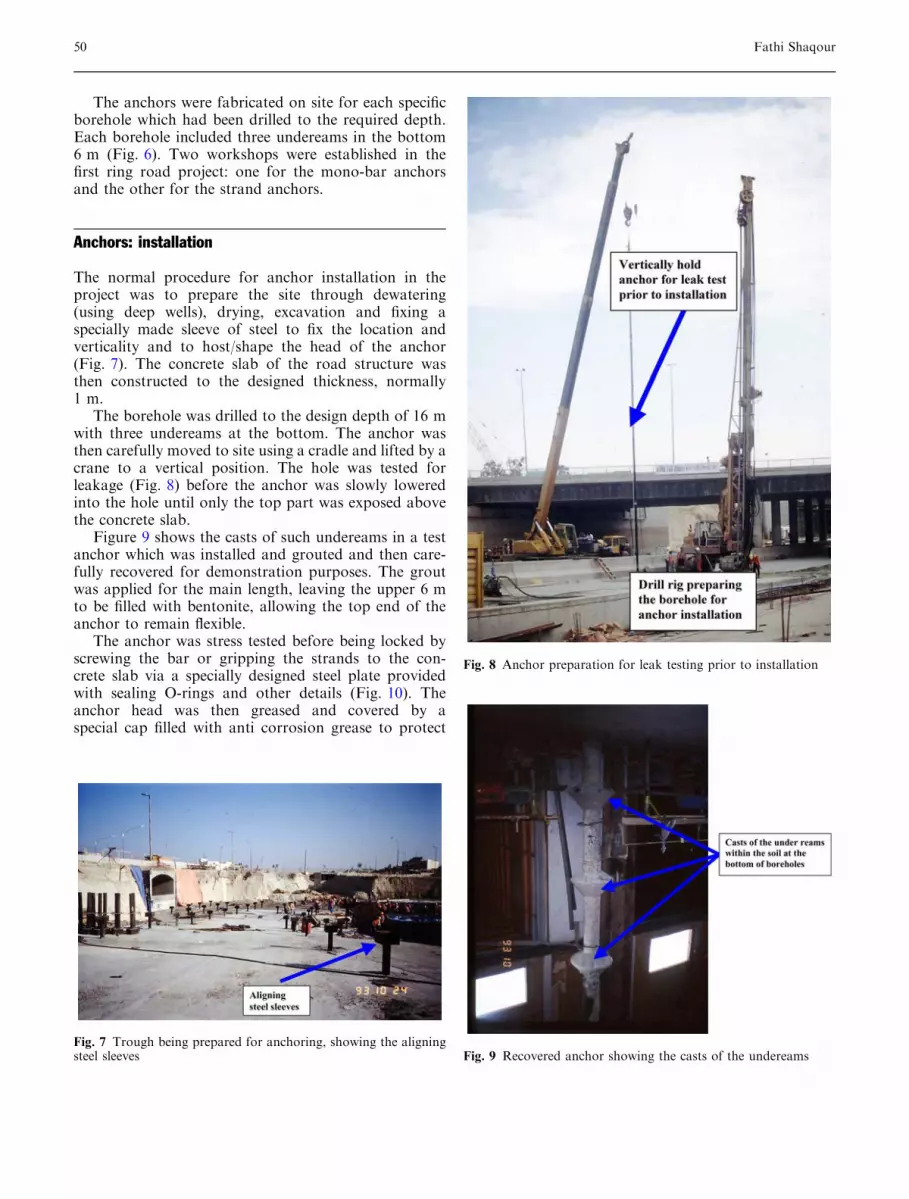
The anchors were fabricated on site for each specificborehole which had been drilled to the required depth.Each borehole included three undereams in the bottom6 m (Fig. 6). Two workshops were established in thefirst ring road project: one for the mono-bar anchorsand the other for the strand anchors.
Anchors: installation
The normal procedure for anchor installation in theproject was to prepare the site through dewatering(using deep wells), drying, excavation and fixing aspecially made sleeve of steel to fix the location andverticality and to host/shape the head of the anchor(Fig. 7). The concrete slab of the road structure wasthen constructed to the designed thickness, normally1 m.
The borehole was drilled to the design depth of 16 mwith three undereams at the bottom. The anchor wasthen carefully moved to site using a cradle and lifted by acrane to a vertical position. The hole was tested forleakage (Fig. 8) before the anchor was slowly loweredinto the hole until only the top part was exposed abovethe concrete slab.
Figure 9 shows the casts of such undereams in a testanchor which was installed and grouted and then care-fully recovered for demonstration purposes. The groutwas applied for the main length, leaving the upper 6 mto be filled with bentonite, allowing the top end of theanchor to remain flexible.
The anchor was stress tested before being locked byscrewing the bar or gripping the strands to the con-crete slab via a specially designed steel plate providedwith sealing O-rings and other details (Fig. 10). Theanchor head was then greased and covered by aspecial cap filled with anti corrosion grease to protect
Fig. 7 Trough being prepared for anchoring, showing the aligningsteel sleeves
Fig. 8 Anchor preparation for leak testing prior to installation
Fig. 9 Recovered anchor showing the casts of the undereams
50 Fathi Shaqour

the steel (Fig. 11). All the strands, joints and headdetails were sealed with O-rings to ensure that therewas no leakage of water to any part of the anchor.Clearly, until the anchor is completed and capped, therisk of corrosion continues to exist if for any reason itcomes into contact with aggressive groundwater.However, if everything goes well during the roadconstruction and installation of the anchors, doubleprotection is ensured. The contract required the an-chors to be warranted by the contractor for a periodof 10 years.
As a result of the Gulf War, which started in August1989, the dewatering system was stopped and the pre-viously excavated deep trenches at the road intersectionswere inundated with groundwater. About 500 strandand 250 mono-bar anchors were only partially com-pleted at that time and were submerged in water withhigh levels of chlorides and sulphates, thus becomingliable to the risk of corrosion either as a general attack,localized attack, or stress corrosion with hydrogenembrittlement.
When the war was over and the Kuwaiti govern-ment resumed its activities, the Ministry of PublicWorks decided to recommence the first ring roadproject and a consultant was asked to assess the
situation. Dewatering was re-started and the ground-water lowered to the required level. Figure 12a and bshows two of the inundated troughs before andduring/after resuming the dewatering. A damageassessment was first undertaken, followed by a com-prehensive testing programme to determine the degreeof corrosion of the partially completed anchors. Thefully completed ones were considered to be safe. Thetesting of samples from the infected anchors wascarried out at different laboratories by different partiesand site tensile strength tests on selected infected an-chors were also undertaken.
Methods of investigation and testing
The first step was to carry out a damage assessmentwhich required the use of a boat to investigate the threeintersections: these now resembled lakes where even fishwas found. Then dewatering was resumed to make thesite dry again in order to allow a full investigation(including the ground anchors) and facilitate theresumption of construction activities.
The ground anchors were classified into four maincategories according to their stage of completion asfollows:
Category 1 installed and grouted, considered at highrisk as no sealing measures had yet been undertaken andthe structural elements were exposed to direct corrosionattack;
Category 2 installed and stress tested but still open tocorrosion attack as the water could penetrate through itsfree end; corrosion will take place while the bar or strandis under tension;
Category 3 capped; the anchor was less susceptible tocorrosion as it had been almost finished, greased andcapped and with all the head details undertaken;
Category 4 completed and covered with mild cementgrout.
A comprehensive testing programme followed to as-sess the degree of corrosion associated with each of thecategories. Some tests were carried out by the Ministryof Public Works (the client) at Kuwait University;Bruckner Grundbau (the contractor) via Dyvwidag &Trefil Arbed/Germany; and CAPCIS/UK as an inde-pendent organization called by the consultant. The fol-lowing tests were included:
Fig. 10 Bearing plates a for strand anchors showing the sealing O-rings, b for mono-bar anchors (long and short sleeves)
Ground anchors in an aggressive hydro-environment 51

1. Physical examination of the infected anchors whilethey were in place, with the intention to examine asdeep as possible.
2. A number of anchors representing the different cat-egories were recovered and corrosion and strengthtesting carried out.
3. Long-term stress tests were undertaken on infectedanchors under higher loads than the design load tocheck their durability (see Fig. 3).When the first ex-humed anchors were tested, salt precipitates weredetected all the way down, which raised some doubtsas to the origin of these salts. As drilling water (localgroundwater) could have been the source, it wasdecided to use a dye when the next anchors wererecovered (Fig. 10). This confirmed the drilling waterto be the source of the salts.
Test results
1. Physical examination of anchors in place: the ex-posed sections of both mono-bar and strand an-chors were cleaned from salt deposits and visuallyexamined.
(a) Mono-bar anchors: The exposed section of the upperpart of the bar had been inundated by salinegroundwater and pits of corrosion were evident upto 250 lm deep, though still within the outer layer(Fig. 13). In some mono-bar anchors the upper partof the grout was cut down to examine the steel bar.These showed no signs of corrosion as the cementgrout appeared to have protected the steel and the
Fig. 11 Completed mono-baranchor (top) showing the bear-ing plate and head of theanchor before it is finallycapped and strand anchor (bot-tom) showing the bearing plate,gripped strands and cap filledwith anti-corrosion greasewhich all will be covered withlight sand and cement grout
52 Fathi Shaqour

low permeability of the cement grout prevented thepenetration of water.
(b) Strand anchors: In the early stages it was incorrectlythought that groundwater would never penetratedown the strand due to the double protection PEsheathing, which extended to the anchor head.However, it was then recognised that water couldhave penetrated along the strand following the voidsaround the central king wire. This would mean thestrand anchors were more susceptible to corrosiondue to the fact that the set of strands in the freelength of the anchor were embedded in PE sheathingencased in a PVC pipe which became filled withwater during the inundation. For this reason cor-rosion could have penetrated much deeper than incase of the mono-bar anchors. Examination of thetop sections of the strands indicated surface corro-sion and pitting of various sizes and degrees in allincomplete anchors (Fig. 14). Microbial effects ofsulphate reducing bacteria (SRB) were evident up toa depth of 1.5 m.
Fig. 13 Pitted mono-bars from infected anchors
Fig. 12 a Trough for construction (top) inundated and (bottom) after dewatering resumed. b Troughs for construction (top) inundated and(bottom) during resumed dewatering
Ground anchors in an aggressive hydro-environment 53

2. Physical examination of exhumed anchors:
(a) Mono-bar anchors: There was very little concernabout deep penetration of groundwater in the caseof the mono-bar anchors and therefore none wererecovered although deep sections were cut for test-ing.
(b) Strand anchors: Recovery was carried out in twostages. An anchor was first exhumed using localgroundwater and left for some time before testingwas undertaken. Corrosion pits were very clearlyseen to the base of the free length. As severalmonths elapsed prior to testing, some corrosioncould have occurred during that period as a resultof the chloride and sulphates in the drilling water.It was decided to exhume more anchors using a dyeto detect the influence of drilling water, whichproved the drilling water penetrated deep into thestrands.
Microscopic examination of sections of the freelength of the recovered anchors conducted by CAPSISindicated a general pit depth of 100 lm although somewere as deep as 250 lm. Sections of the fixed ends of theanchor tendon, which had been stripped of PE sheathingand embedded in cement grout during fabrication,
showed no signs of pitting due to the protection affordedby the cement grout.
3. Tensile strength of pitted steel bars from infectedanchors: a piece of the steel bar cut from an infectedmono-bar anchor was tested for tensile strength atthe University of Kuwait. The results indicate thatthe strength had not been reduced significantly as aresult of corrosion (Fig. 15).
4. Tensile strength of pitted wires of strands from in-fected anchors: pieces of wire from strands of ex-humed anchors were tested for tensile strength whileunder the corrosion environment to show the possibleinfluence of continued corrosion and the influence ofoxygen embrittlement. The test results indicate thatthe infected wires showed a similar strength as did thestandard wires, suggesting that the present corrosionpits have no influence on the strength of the strands.However, it was appreciated that the pits may act as astress focus during the life time of the anchor.
Contractors’ reports noted chloride pitting at thebottom of the anchors. They concluded that the tensilestrength had been reduced by 3–5% and the fatiguestrength by 10–15%. However, such pitting was re-corded in anchors which had been recovered using thelocal saline groundwater and left for a considerable time.As a consequence, it was not clear whether the water inthe anchor was due to inundation or had been drill in-duced. Further exhumation using fresh water and pig-ment dye proved that the contamination was caused bythe drilling water. Based on these observations it wasconcluded that penetration of groundwater was limitedto 1.5 m where the trapped air and meniscus forces ofthe voids could have prevented further penetration.
In order to predict the possibility of hydrogenembrittlement, slow strain tensile tests were conducted
Fig. 14 Pitted strands from infected anchors
Fig. 15 Tensile strength of pitted steel bar from infected anchors
54 Fathi Shaqour

for pitted strand sections immersed in an aggressivesolution. The tests gave positive results.
Site stress tests on infected anchors: some infectedanchors were selected to be stress tested on site usingloads higher than the design proof loading. Tensilestresses were applied using a jacking system with cali-brated load cells, where the load is recorded versus strainand time for a period of 3 days. The applied tensilestress was up to 20% higher than the design loading.Figure 16 shows the site tensile strength test set up andgives the results of these tests. These indicate that theinfected anchors behaved well under the applied stressesand showed no failure during the test period of 3 days.A decline in strength with time is evident for some al-though the minimum strength reached was still abovethe design loading. The argument was whether the in-fected anchors would continue to hold the stresses forthe time period of the project. In addition, it was notclear whether the corrosion had halted or would con-tinue, especially in the strand anchors where the salinegroundwater could have penetrated to such depths thatthey could not be cleaned.
Remedial measures
Serious discussions were held between the client, thecontractor and the consultant on the expected behaviourof the infected anchors. It was suggested by theconsultant that they should be cleaned as deep as pos-sible and then completed as per the specifications butusing top bearing plates with longer sleeves. The anchorswere accordingly cleaned of dust and rust and coveredwith nylon sheets for protection until completion(Fig. 17).
The contractor, however, refused to take theresponsibility of warranting the infected anchors andinsisted they should all be replaced. Such a scenario
Fig. 16 Onsite tensile strength testing of an infected anchor a testset-up, b test results
Fig. 17 Infected anchors a during cleaning of strands b aftercleaning and covering with PE sheets for protection untilcompletion
Ground anchors in an aggressive hydro-environment 55

would delay the project and could involve huge delaypenalties. After long and difficult discussions, in orderthat the project could be completed on time, the Min-istry of Public Works agreed to take responsibility forthe infected anchors while the contractor would con-tinue to be responsible for the whole project. As a pre-cautionary measure, a few dewatering deep wells wouldbe kept ready for use in case any problem occurred inthe future.
Conclusions
As the result of the discontinuation of a road project dueto the Gulf War, anchors which were being emplaced tocounterbalance the hydraulic uplift pressure where theroad was being constructed below the ground water levelwere subject to inundation and the possibility of corro-sion.
(1) Mono-bar anchors showed less susceptibility tocorrosion than strand anchors as a result ofgroundwater attack.
(2) Completed anchors proved to behave correctly andshowed no signs of corrosion after being floodedwith saline groundwater to a depth of about 6 m fora period of about 12 months.
(3) Test results indicate that the design load for theanchors seemed to have been high with a large factorof safety.
(4) Tests performed on the infected anchors indicatethat the degree of corrosion (pit depth) at the presenttime is below the critical threshold. This was con-firmed by the results of tensile strength tests whichshowed almost no reduction in strength due to cor-rosion. However, the British Standard Code ofPractice 8081:1989 states that ‘‘tendons showingsigns of pitting should not be used’’. In view of this,it is open to question whether corrosion will con-tinue and the current corrosion pits will act as astress focus.
(5) The infected anchors could form a unique case fortesting the specifications for ground anchors. Con-tinuous monitoring of the behaviour of such anchorscould assist in the reconsideration of the criteria fordesigning ground anchors.
(6) The legal aspects of the current ground anchor issueare very important. In the present case, after lengthydiscussions the Kuwaiti Government agreed to takeresponsibility for the infected anchors and the con-tractor for the whole project. It raises the question asto how such situations might be dealt with within thecontract in the future and the advisability of insuringfor such events.
Acknowledgement The author is grateful to the Ministry of PublicWorks of Kuwait and to Montgomery Watsons and the GulfConsult of Kuwait for permitting the use of the data in this paper.
References
Al-Hajji YY (1976). A quantitative hydro-logical study of field ‘‘A’’ south of Ku-wait. MSc Thesis, Graduation College,Ohio University, OH, pp 116
Al-Kulaib AA (1984). The climate of Ku-wait. Directorate General of Civil Avi-ation. Climatological Division,Meteorological Deptartment, Kuwait
British Standards 8081 (1989). Britishstandard code of practice for groundanchorages
Burdon DG, Al-Sharhan A (1968) ‘‘Theproblem of palaeokarst Dammamlimestone aquifer in Kuwait’’. J Hydrol6:385–404
Davies CCS (1965). ‘‘The post Jurassictectonic history of Kuwait and vicinity.Kuwait oil company’’ KR 11:14
Fuchs W, Gathinger TE, Holzer HF (1968)Explanatory text to the synoptic geo-logic map of Kuwait: a surface geologyof Kuwait and the neutral zone. Geo-logical Survey of Austria, Vienna
Higginbotttom IE (1954). Report on thesurface geology of Kuwait with refer-ence to the natural resources of buildingmaterial. Ministry of Public Works,Kuwait
Khalaf FI, Gharib IM, Al-Hashash MZ(1984) ‘‘Types and characteristics of theRecent surface deposits of Kuwait,Arabian Gulf’’. J Arid Environ 7:9–33
Milton DI (1967). ‘‘Geology of the ArabianPeninsula, Kuwait’’. Am Geol SurvProf Paper 560-F:7
Mitchel RC (1957) ‘‘Notes on the geologyof Western Iraq and Northern SaudiArabia’’. Geol Rundaschau 46:467–493
Omar S, Al-Yaqubi A, Senay Y (1981)‘‘Geology and groundwater hydrologyof the State of Kuwait’’. J Gulf ArabianPeninsula Stud—Kuwait Univ 2:1–51
Owen RMS, Nasr SN (1958). ‘‘Stratigraphyof Kuwait–Basra area.’’ In: Habitat ofoil, symposium of the American Asso-ciation of petroleum geologists. Tulsa,Oklahoma, pp 1252–1278
Parsons Corporation (1963). Groundwaterresources of Kuwait, vols 1 and 11. LosAngeles, CA
Salman AS (1979). Geology of the Jal Az-Zor, Al-Liyah area, Kuwait. MSc The-sis, Kuwait
Shaqour FM (1990). Effects of groundwa-ter level changes on the engineeringproperties of desert sands in Kuwait,PhD Thesis, Leeds University, UK
56 Fathi Shaqour


