Embed Size (px)
Citation preview
Korean J. Chem. Eng., 24(4), 567-576 (2007)
JOURNAL REVIEW
567
†To whom correspondence should be addressed.
E-mail: [email protected] or [email protected]
Integrated water resource management through water reuse network designfor clean production technology: State of the art
ChangKyoo Yoo†, Tae Young Lee*, Jiyong Kim**, Il Moon**, Jae Hak Jung***,Chonghun Han****, Jong-Min Oh and In-Beum Lee*
Department of Environmental Science and Engineering/Center for Environmental Studies, College of Environmental and Applied Chemistry, Kyung Hee University, Seocheon-dong, Giheung-gu, Yongin-si, Gyeonggi-do 446-701, Korea
*Department of Chemical Engineering, POSTECH, San 31 Hyoja Dong, Pohang 790-784, Korea**Department of Chemical Engineering, Yonsei University, Seoul 120-749, Korea
***School of Display and Chemical Engineering, Yeungnam University, Daedong, Gyeongsan 712-749, Korea****School of Chemical and Biological Engineering, Seoul National University, Seoul 151-744, Korea
(Received 19 September 2006 • accepted 10 January 2007)
Abstract−This article considers new and existing technologies for water reuse networks for water and wastewater
minimization. For the systematic design of water reuse networks, the theory of the water pinch methodology and the
mathematical optimization are described, which are proved to be effective in identifying water reuse opportunities.
As alternative solutions, evolutionary solutions and stochastic design approaches to water system design are also il-
lustrated. And the project work flow and an example in a real plant are examined. Finally, as development is in the
forefront in process industries, this paper will also explore some research challenges encountered in this field such as
simultaneous water and energy minimization, energy-pinch design, and eco-industrial parks (EIP).
Key words: Eco-Industrial Park (EIP), Mathematical Optimization, Process Integration, Water System Design, Water and
Wastewater Minimization, Water Reuse Network, Water Pinch Technology
INTRODUCTION
Water is one of the most important natural resources being used
in the process industry. Process water, for instance, can be used as
solvent in a direct or indirect way, for transportation, cleaning and
cooling medium. On the other hand, wastewater is generated in the
different processes and utility systems, creating a stream which even-
tually needs to be treated. However, in recent years, the increased
price of fresh water and the increased cost for processing wastewa-
ter treatment to meet environmental requirements has orced process
industries to search for ways that efficiently minimize the amount
of water usage and wastewater generation. A number of efforts for
the clean production technology have been increasingly made within
not at the end-of-pipe technologies but toward achieving the goal
of fundamental structural changes that allow extensive water reuse
or decreasing wastewater generation [1-11].
Two strategies can be implemented for reducing water demand
in a plant: (1) one strategy consists of modifying individual process
and utility units to reduce their inherent need for water (i.e., includ-
ing replacing water-cooling with air cooling, improving control of
boiler and cooling tower blow down, and increasing the number of
stages in an extraction unit that employs water as its extractant);
(2) the engineer seeks opportunities to use the outlet water from
one operation to satisfy the water requirement of another or the same
operation. In some cases, the water may require some regeneration
prior to re-use as examples these include pH adjustment, filtration,
membrane separation, sour-water stripping, and ion exchange. Spe-
cifically, systematic strategies for such reuse maximization can lower
freshwater usage and wastewater discharges by 50% or more, while
also significantly reducing capital investment in treatment facilities
[12].
In turn, there are four methods to water minimization: process
changes, water reuse, regeneration reuse and regeneration recycling.
Identifying the optimum water reuse in accordance with process
constraints is a combinatorial optimization problem where all possi-
ble maximum reuse structures of the systems are analyzed in a tree-
type fashion using a branch and bound strategy with maximum viable
options for reuse structures of the system are analyzed. In identify-
ing water reuse opportunities, systematic methodologies for analyz-
ing water networks and reducing water cost have been suggested
[2,5,13-15]. There have been two approaches to obtaining funda-
mental designs of the water-using systems:
1. Conceptual graphical design (water pinch)
2. Mathematical optimization
A simple but elegant solution is offered by water pinch analysis,
which recommends simple methods and beneficial results when
applied to water-using industries [3]. However, water pinch analy-
ses suffer from a major drawback: as the number of contaminants
increases it becomes increasingly difficult to be applied. Another
approach is to use mathematical optimization to treat the multiple
contaminants or constraints, economic cost evaluation, and plant
layout. Despite the progress made in optimization algorithms, they
often require considerable computing time and do not guarantee a
global solution if the complexity of the design problem rises due to
the number of process units, contaminants and possible network
568 C. Yoo et al.
July, 2007
topologies [16].
In the first section, this paper reviews the concepts underlying
water pinch analysis, the mathematical optimization and its approach
to water and wastewater minimization. In the second section, re-
search works of alternative solutions, stochastic design and batch-
reusing approaches to water system design are illustrated. Follow-
ing this discussion, the project workflow and case studies in sev-
eral different industries will be detailed following conclusions ex-
ploring the recent research challenges.
WATER PINCH TECHNOLOGY
Generally, it is estimated that the water pinch achieves large re-
duction in effluent flow and contaminant loading by identifying water
re-use, recycling and regeneration opportunities within the process
as the method can be achieved through a typical water flow reduc-
tion of 30% and a significant COD reduction before final treat-
ment. Water pinch is a systematic technique for analyzing water
networks and reducing water costs for processes. It uses a graphi-
cal design method to identify and optimize the best water re-use,
re-generation and effluent treatment opportunities [17]. The pinch
methodology was initially developed for the optimization of heat
exchanger networks (heat pinch) by Linhoff [18];this is best illus-
trated by El-Halwagi and co-workers [19-21] and by Smith and co-
workers [2-4,22] who have pioneered the fundamental theoretical
formulations for the application of pinch analysis principles to water
problems.
Simply, the motto of water pinch technology is rephrased into a
simple logic: “the best way to minimize pollution is not to produce
it”. Therefore, find in-process solutions, before focusing on the ‘end
of pipe’!” [17]. Pinch analysis principles to waste and wastewater
problems have been successfully applied to a broad range of in-
dustries with freshwater savings of 15-40% and wastewater savings
of 20-50%; a listing of the application results is given in Table 1 [17].
Wang and Smith [2] introduced a water pinch method for tar-
geting maximum water reuse for single contaminant problems based
on the construction of a composite curve of the limiting water pro-
files for each operation. The basic idea is that wastewater can be
re-used directly in other operations when water-using operations
can accept the contamination level of previous operations. The first
task consists of developing a limiting water profile for each water-
using process operation, based on maximum inlet and outlet con-
centration for the water stream for each operation [12].
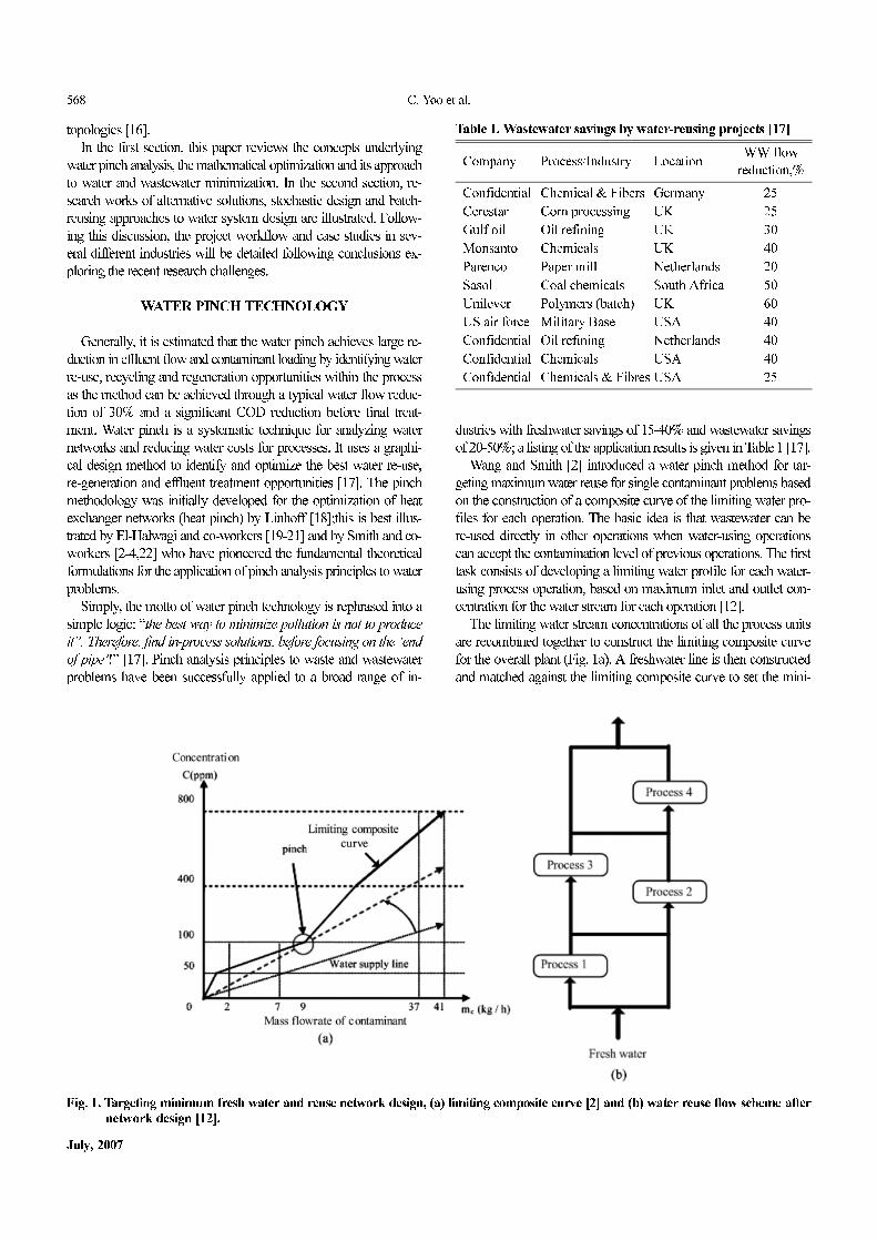
The limiting water stream concentrations of all the process units
are recombined together to construct the limiting composite curve
for the overall plant (Fig. 1a). A freshwater line is then constructed
and matched against the limiting composite curve to set the mini-
Fig. 1. Targeting minimum fresh water and reuse network design, (a) limiting composite curve [2] and (b) water reuse flow scheme afternetwork design [12].
Table 1. Wastewater savings by water-reusing projects [17]
Company Process/Industry LocationWW flow
reduction,%
Confidential Chemical & Fibers Germany 25
Cerestar Corn processing UK 25
Gulf oil Oil refining UK 30
Monsanto Chemicals UK 40
Parenco Paper mill Netherlands 20
Sasol Coal chemicals South Africa 50
Unilever Polymers (batch) UK 60
US air force Military Base USA 40
Confidential Oil refining Netherlands 40
Confidential Chemicals USA 40
Confidential Chemicals & Fibres USA 25
Integrated water resource management through water reuse network design for clean production technology: State of the art 569
Korean J. Chem. Eng.(Vol. 24, No. 4)
mum fresh water demand for the overall plant. The minimum fresh-
water line touches the limiting composite curve at two points: at
zero concentration and at an intermediate position called the pinch
point (100 ppm concentration). This line, which corresponds to the
minimum water flow rate required for the plant, establishes the “tar-
get” for maximizing water reuse. By maximizing the outlet con-
centration of the water supply line, the minimum consumption of
freshwater is obtained and the slope of the water supply line gives
the target for minimum fresh water flow rate (90 t/h). At the pinch,
the driving force goes to a minimum since the limiting profile data
contains the process constraints of minimum driving force. The lim-
iting composite curve construction also shows the critical section
of the plant (regions close to pinch concentration) that require es-
pecially close attention in order to achieve the minimum water re-
quirement [7,12].
To develop the water-reuse network that minimizes the fresh-
water demand, Wang and Smith [2,3] use network-design method-
ology analogous to the pinch design method from the heat integra-
tion. The initial network tends to have a complex structure, but an
evolutionary and heuristic procedure then simplifies this to yield a
practical network (Fig. 1b, [12]). However, the graphical design of
water pinch is difficult to apply to large problems when dealing with
multiple contaminant or constraints, economic cost evaluation, and
plant layout. Mathematical programming approaches have been
used to optimize system cost and account for all contaminants and
trade-offs. Several research works have developed a water-reuse
design based on mathematical optimization techniques to overcome
the difficulties of the water pinch approach [5,23].
MATHEMATICAL OPTIMIZATION
Mathematical optimization can be used as an effective method
for the analysis, synthesis, and retrofit of water-use networks for
industrial water reuse and wastewater minimization and of distrib-
uted effluent treatment systems for minimizing the wastewater treat-
ment flow rate. Man and Liu [24] introduced the method of super-
structure to formulate the water network as linear programming (LP)
and nonlinear programming (NLP) for single and multiple con-
taminants systems. The solution of those models is the optimal allo-
cation of species and streams throughout the process with mini-
mum freshwater flow rate target.
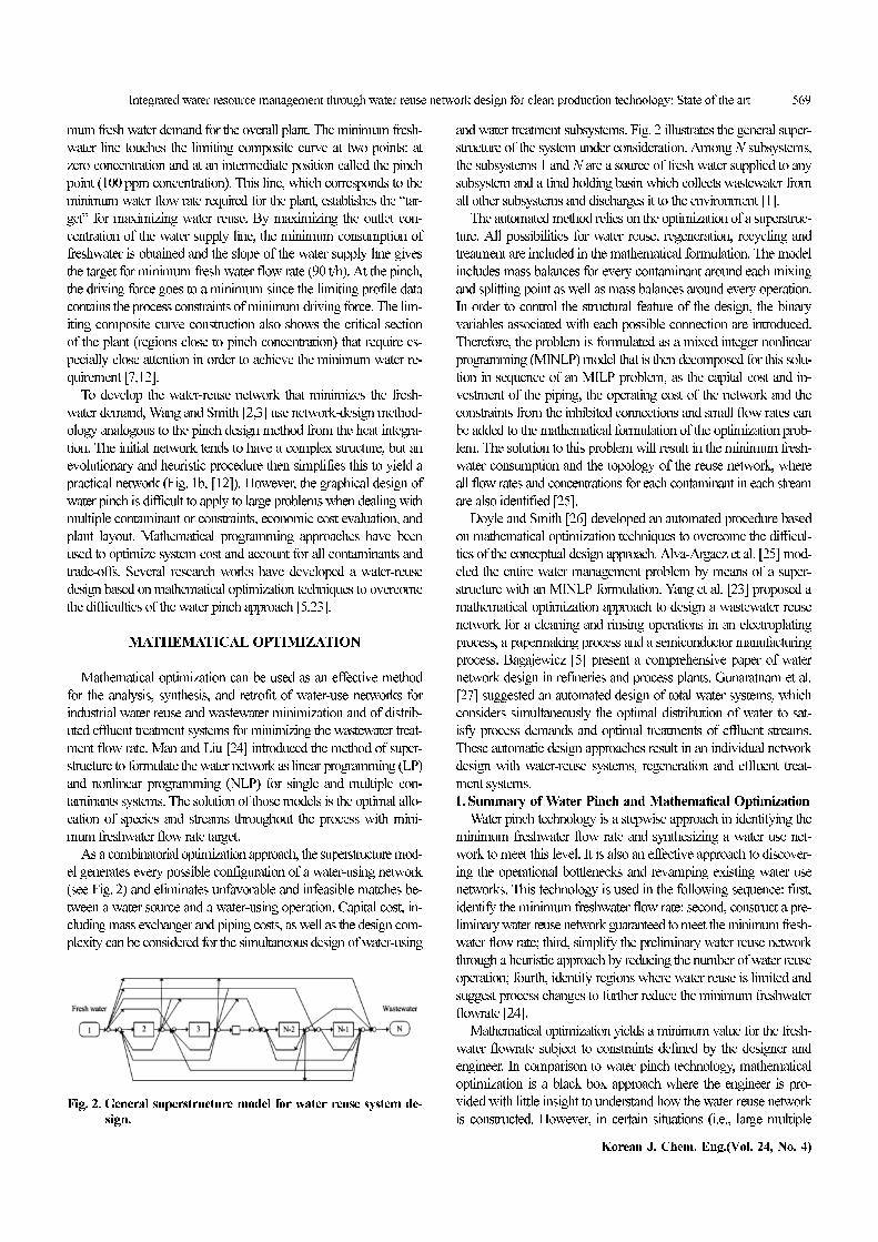
As a combinatorial optimization approach, the superstructure mod-
el generates every possible configuration of a water-using network
(see Fig. 2) and eliminates unfavorable and infeasible matches be-
tween a water source and a water-using operation. Capital cost, in-
cluding mass exchanger and piping costs, as well as the design com-
plexity can be considered for the simultaneous design of water-using
and water treatment subsystems. Fig. 2 illustrates the general super-
structure of the system under consideration. Among N subsystems,
the subsystems 1 and N are a source of fresh water supplied to any
subsystem and a final holding basin which collects wastewater from
all other subsystems and discharges it to the environment [1].
The automated method relies on the optimization of a superstruc-
ture. All possibilities for water reuse, regeneration, recycling and
treatment are included in the mathematical formulation. The model
includes mass balances for every contaminant around each mixing
and splitting point as well as mass balances around every operation.
In order to control the structural feature of the design, the binary
variables associated with each possible connection are introduced.
Therefore, the problem is formulated as a mixed integer nonlinear
programming (MINLP) model that is then decomposed for this solu-
tion in sequence of an MILP problem, as the capital cost and in-
vestment of the piping, the operating cost of the network and the
constraints from the inhibited connections and small flow rates can
be added to the mathematical formulation of the optimization prob-
lem. The solution to this problem will result in the minimum fresh-
water consumption and the topology of the reuse network, where
all flow rates and concentrations for each contaminant in each stream
are also identified [25].
Doyle and Smith [26] developed an automated procedure based
on mathematical optimization techniques to overcome the difficul-
ties of the conceptual design approach. Alva-Argaez et al. [25] mod-
eled the entire water management problem by means of a super-
structure with an MINLP formulation. Yang et al. [23] proposed a
mathematical optimization approach to design a wastewater reuse
network for a cleaning and rinsing operations in an electroplating
process, a papermaking process and a semiconductor manufacturing
process. Bagajewicz [5] present a comprehensive paper of water
network design in refineries and process plants. Gunaratnam et al.
[27] suggested an automated design of total water systems, which
considers simultaneously the optimal distribution of water to sat-
isfy process demands and optimal treatments of effluent streams.
These automatic design approaches result in an individual network
design with water-reuse systems, regeneration and effluent treat-
ment systems.
1. Summary of Water Pinch and Mathematical Optimization
Water pinch technology is a stepwise approach in identifying the
minimum freshwater flow rate and synthesizing a water use net-
work to meet this level. It is also an effective approach to discover-
ing the operational bottlenecks and revamping existing water use
networks. This technology is used in the following sequence: first,
identify the minimum freshwater flow rate; second, construct a pre-
liminary water reuse network guaranteed to meet the minimum fresh-
water flow rate; third, simplify the preliminary water reuse network
through a heuristic approach by reducing the number of water reuse
operation; fourth, identify regions where water reuse is limited and
suggest process changes to further reduce the minimum freshwater
flowrate [24].
Mathematical optimization yields a minimum value for the fresh-
water flowrate subject to constraints defined by the designer and
engineer. In comparison to water pinch technology, mathematical
optimization is a black box approach where the engineer is pro-
vided with little insight to understand how the water reuse network
is constructed. However, in certain situations (i.e., large multipleFig. 2. General superstructure model for water reuse system de-
sign.
570 C. Yoo et al.
July, 2007
contaminant problems), mathematical optimization outperforms water
pinch technology. In addition, mathematical optimization has an
advantage when the choice of a model for each water use opera-
tion must be flexible; these expenses may include connection, op-
erating, and piping and pumping costs. Since the mathematical opti-
mization approach of NLP and MINLP is sensitive to the choice
of initial values, it may identify a local optimum and less than global
optimal treatment-network configuration; thus, the two approaches
are complementary. The visualization ability improves engineering
understanding and the mathematical model allows the handling of
complex problems [5,12,24].
ALTERNATIVE SOLUTIONS
OF WATER-REUSING NETWORK
1. Evolutionary Solutions to Water Reuse Network
Despite the efforts made to overcome this drawback, in finding
the optimal reuse network based on deterministic algorithms, how-
ever, it is often difficult to remedy the mathematical optimization
problems, such as non-convexity, linearization, and locality. Since
the mathematical representation for the multiple contaminants be-
comes the class of nonlinear programming (NLP), this class of prob-
lem has more than one local optimum [28]. The accuracy and effi-
ciency of conventional techniques for finding the global optimum
depends on the initial guess. The inappropriate one leads to the solu-
tion getting struck at the local optimum. A well-known technique
for avoiding local optima in improving search is stochastic optimi-
zations such as evolutionary algorithm [16].
Stochastic optimizations using evolutionary algorithm of genetic
algorithm (GA), simulated annealing (SA) and ant colony optimi-
zation (ACO), have been developed to find the optimal solutions
to non-convex problems [16,28,29]. For this approach, Garrard and
Fraga [29] suggested a new methodology for the synthesis of mass
exchange network (MEN) with regeneration using GA. They de-
fined an encoding for MEN synthesis problems that determines both
the structure and the actual mass exchanges simultaneously, which
does not require the solution of a nonlinear program as part of the
fitness evaluation. It represents that all encoded solutions are feasi-
ble and require a simple evaluation to yield a cost for a small-sized
problem, which results in an efficient GA to eliminate the need for
a penalty function under a large class of the water reuse synthesis.
For other large-sized problems, the number of infeasible solutions
is small and the convergence of the GA operator is quite fast.
In discussing advancing Garrad and Fraga [29], Prakotpol and
Srinophakun [28] developed a GA-based program called the GAP-
inch to solve the wastewater minimization problem. It covers both
single and multiple contaminant systems. Moreover, the GA was
tested on three separate water-using case studies--single contami-
nant of water reuse, regeneration recycle, and multiple contaminants
of water reuse--and compared to a mathematical program. For single
contaminant, the results from GAPinch and mathematical approach
reach the same value of minimum freshwater consumption but pres-
ent different configurations. For multiple contaminants, GAPinch
gives better than or equal minimum freshwater consumption when
compared to the mathematical approach because this software pack-
age could get in a local optimum while GAs has the ability to escape
from there. A further development should include cost-related func-
tions such as cost constraints of piping and pumping for more con-
ceptual design.
Lavric et al. [16] suggested a hybrid optimization based on an
improved version of GA for water consumption and wastewater
network topology. It uses each network’s internal flow as a gene,
assembling the topology into a chromosome. The restrictions are
applied with naturally rejecting genes outside their feasible domain.
When several water supply sources are available (fresh or contam-
inated), it enables their allocation according to closeness between
their contamination level and the inlet restrictions for each unit.
2. Stochastic Design Approaches in Water Reuse Network
Most of the mathematical models in water reuse systems have
attempted the water reuse problem under two assumptions; first,
water always removes fixed loads of contaminants, and another as-
sumption is that solubility and corrosion limits can be used to set
maximum inlet and outlet concentration units imposed on contam-
inants. These assumptions are necessary to simplify the problem
and make it easier to solve [5]. In water reuse processes, concen-
trations of contaminants in the water reuse process may reach their
solubility limits, but such limits are functions of process parameters
(temperature and pressure). Hence the loads of contaminants are
variable with respect to the flow rate [30]. This suggests that the
design of wastewater networks should be resilient and able to ac-
commodate different pollutant levels which may easily result from
deviations in operating conditions. From this point of view, a sto-
chastic design for the uncertainty of water reuse network can be
carried out.
To incorporate the uncertainty associated with operation conditions,
a stochastic design in water reuse network usually has the follow-
ing procedure. (1) The process identification and the problem for-
mulation are the first step. (2) A deterministic optimization model
is developed and tested. This model searches for the network con-
figuration with minimum freshwater use and optimal wastewater
reuse and regeneration/reuse. (3) The third step involves a sensitiv-
ity analysis in which uncertainty is introduced as maximum and
minimum ranges in operating conditions. (4) A stochastic formula-
tion is developed based on fuzzy programming [31] or the two-stage
recourse problem method with finite number of realization; in partic-
ular, a two-stage stochastic optimization approach [32] is widely
used.
In a two-stage stochastic optimization approach, the uncertain
model parameters are considered random variables with an associ-
ated probability distribution and the decision variables are classi-
fied into two stages. The first-stage variables correspond to those
decisions that need to be made prior to the realization of the un-
certainty. The second-stage or recourse variables correspond to those
decisions made after the uncertainty is unveiled and are usually re-
ferred to as wait-and-see decisions. After the first-stage decisions
are taken and the random events realized the second stage deci-
sions are made subject to the restrictions imposed by the second-
stage problem. Due to the stochastic nature of the performance as-
sociated with the second-stage decisions, the objective function con-
sists of the sum of the first-stage performance measure and the ex-
pected second-stage performance [30].
3. Water-reusing Network Design in Batch Industries
The water streams for continuous processes are specified by flow
rate, concentrations of contaminant, temperature, heat capacity, etc.
Integrated water resource management through water reuse network design for clean production technology: State of the art 571
Korean J. Chem. Eng.(Vol. 24, No. 4)
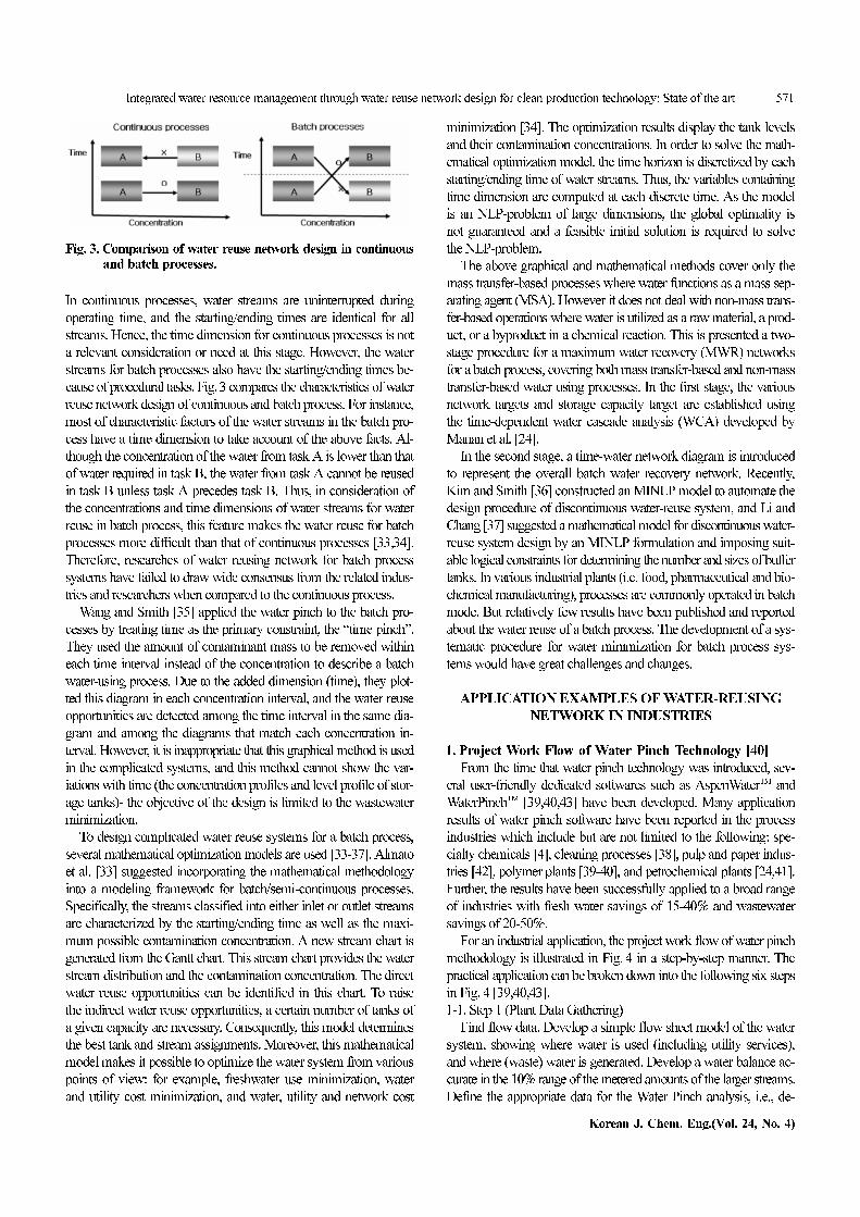
In continuous processes, water streams are uninterrupted during
operating time, and the starting/ending times are identical for all
streams. Hence, the time dimension for continuous processes is not
a relevant consideration or need at this stage. However, the water
streams for batch processes also have the starting/ending times be-
cause of procedural tasks. Fig. 3 compares the characteristics of water
reuse network design of continuous and batch process. For instance,
most of characteristic factors of the water streams in the batch pro-
cess have a time dimension to take account of the above facts. Al-
though the concentration of the water from task A is lower than that
of water required in task B, the water from task A cannot be reused
in task B unless task A precedes task B. Thus, in consideration of
the concentrations and time dimensions of water streams for water
reuse in batch process, this feature makes the water reuse for batch
processes more difficult than that of continuous processes [33,34].
Therefore, researches of water reusing network for batch process
systems have failed to draw wide consensus from the related indus-
tries and researchers when compared to the continuous process.
Wang and Smith [35] applied the water pinch to the batch pro-
cesses by treating time as the primary constraint, the “time pinch”.
They used the amount of contaminant mass to be removed within
each time interval instead of the concentration to describe a batch
water-using process. Due to the added dimension (time), they plot-
ted this diagram in each concentration interval, and the water reuse
opportunities are detected among the time interval in the same dia-
gram and among the diagrams that match each concentration in-
terval. However, it is inappropriate that this graphical method is used
in the complicated systems, and this method cannot show the var-
iations with time (the concentration profiles and level profile of stor-
age tanks)- the objective of the design is limited to the wastewater
minimization.
To design complicated water reuse systems for a batch process,
several mathematical optimization models are used [33-37]. Almato
et al. [33] suggested incorporating the mathematical methodology
into a modeling framework for batch/semi-continuous processes.
Specifically, the streams classified into either inlet or outlet streams
are characterized by the starting/ending time as well as the maxi-
mum possible contamination concentration. A new stream chart is
generated from the Gantt chart. This stream chart provides the water
stream distribution and the contamination concentration. The direct
water reuse opportunities can be identified in this chart. To raise
the indirect water reuse opportunities, a certain number of tanks of
a given capacity are necessary. Consequently, this model determines
the best tank and stream assignments. Moreover, this mathematical
model makes it possible to optimize the water system from various
points of view: for example, freshwater use minimization, water
and utility cost minimization, and water, utility and network cost
minimization [34]. The optimization results display the tank levels
and their contamination concentrations. In order to solve the math-
ematical optimization model, the time horizon is discretized by each
starting/ending time of water streams. Thus, the variables containing
time dimension are computed at each discrete time. As the model
is an NLP-problem of large dimensions, the global optimality is
not guaranteed and a feasible initial solution is required to solve
the NLP-problem.
The above graphical and mathematical methods cover only the
mass transfer-based processes where water functions as a mass sep-
arating agent (MSA). However it does not deal with non-mass trans-
fer-based operations where water is utilized as a raw material, a prod-
uct, or a byproduct in a chemical reaction. This is presented a two-
stage procedure for a maximum water recovery (MWR) networks
for a batch process, covering both mass transfer-based and non-mass
transfer-based water using processes. In the first stage, the various
network targets and storage capacity target are established using
the time-dependent water cascade analysis (WCA) developed by
Manan et al. [24].
In the second stage, a time-water network diagram is introduced
to represent the overall batch water recovery network. Recently,
Kim and Smith [36] constructed an MINLP model to automate the
design procedure of discontinuous water-reuse system, and Li and
Chang [37] suggested a mathematical model for discontinuous water-
reuse system design by an MINLP formulation and imposing suit-
able logical constraints for determining the number and sizes of buffer
tanks. In various industrial plants (i.e. food, pharmaceutical and bio-
chemical manufacturing), processes are commonly operated in batch
mode. But relatively few results have been published and reported
about the water reuse of a batch process. The development of a sys-
tematic procedure for water minimization for batch process sys-
tems would have great challenges and changes.
APPLICATION EXAMPLES OF WATER-REUSING
NETWORK IN INDUSTRIES
1. Project Work Flow of Water Pinch Technology [40]
From the time that water pinch technology was introduced, sev-
eral user-friendly dedicated softwares such as AspenWaterTM and
WaterPinchTM [39,40,43] have been developed. Many application
results of water pinch software have been reported in the process
industries which include but are not limited to the following: spe-
cialty chemicals [4], cleaning processes [38], pulp and paper indus-
tries [42], polymer plants [39-40], and petrochemical plants [24,41].
Further, the results have been successfully applied to a broad range
of industries with fresh water savings of 15-40% and wastewater
savings of 20-50%.
For an industrial application, the project work flow of water pinch
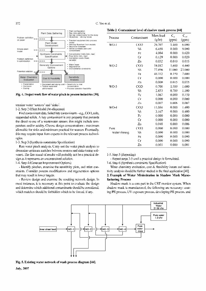
methodology is illustrated in Fig. 4 in a step-by-step manner. The
practical application can be broken down into the following six steps
in Fig. 4 [39,40,43].
1-1. Step 1 (Plant Data Gathering)
Find flow data. Develop a simple flow sheet model of the water
system, showing where water is used (including utility services),
and where (waste) water is generated. Develop a water balance ac-
curate in the 10% range of the metered amounts of the larger streams.
Define the appropriate data for the Water Pinch analysis, i.e., de-
Fig. 3. Comparison of water reuse network design in continuousand batch processes.
572 C. Yoo et al.
July, 2007
termine water ‘sources’ and ‘sinks’.
1-2. Step 2 (Plant Model Development)
Find contaminant data. Select key contaminants - e.g., COD, salts,
suspended solids. A key contaminant is any property that prevents
the direct re-use of a wastewater stream; this might include tem-
perature and/or acidity. Choose design concentrations - maximum
allowable for sinks and minimum practical for sources. Eventually,
this may require input from experts in the relevant process technol-
ogies.
1-3. Step 3 (Synthesis constraints Specification)
Run water pinch analysis. Carry out the water pinch analysis to
determine optimum matches between sources and sinks (using soft-
ware). The first round of results will probably not be a practical de-
sign as it represents an unconstrained solution.
1-4. Step 4 (Generate Improvement Options)
- Identify pinches, examine the sensitivity plots, and relax con-
straints. Consider process modifications and regeneration options
that may result in lower targets.
- Review design and examine the resulting network design. In
most instances, it is necessary at this point to evaluate the design
and determine which additional contaminants should be considered,
which matches should be forbidden which to be forced, if any.
1-5. Step 5 (Repeating)
- Repeat steps 3-5 until a practical design is formulated.
1-6. Step 6 (Synthesis constraints Specification)
Water chemistry evaluation, cost & feasibility issues and sensi-
tivity analysis should be further studied in the final application [40].
2. Example of Water Minimization in Shadow Mask Manu-
facturing Process
Shadow mask is a core part in the CRT monitor system. When
shadow mask is manufactured, the following are necessary: coat-
ing PR process, UV exposure process, developing PR process, and
Fig. 4. Project work flow of water pinch in process industries [39].
Fig. 5. Existing water network of wash process diagram [44].
Table 2. Contaminant level of shadow mask process [44]
Process ContaminantMass load
(g/hr)
Cin
(ppm)
Cout
(ppm)
WO-1 COD
SS
Fe
Cr
Zn
29.707
06.458
04.004
00.129
00.032
01.400
08.000
00.000
00.000
00.010
06.000
09.000
00.620
00.020
00.015
WO-2 COD
SS
Fe
Cr
Zn
18.082
77.496
48.112
00.000
00.000
01.600
11.000
00.150
00.000
00.015
04.400
23.000
07.600
00.000
00.015
WO-3 COD
SS
Fe
Cr
Zn
00.708
02.833
01.062
00.000
00.007
01.500
00.700
00.000
00.000
00.006
01.600
01.100
00.150
00.000
00.007
WO-4 COD
SS
Fe
Cr
Zn
11.084
03.167
00.000
00.000
00.048
00.000
00.000
00.000
00.000
00.000
01.400
00.400
00.000
00.000
00.006
Pure
water rinsing
COD
SS
Fe
Cr
Zn
00.000
00.000
00.000
00.000
00.001
00.000
00.000
00.000
00.000
00.000
00.000
00.000
00.000
00.000
00.001
Integrated water resource management through water reuse network design for clean production technology: State of the art 573
Korean J. Chem. Eng.(Vol. 24, No. 4)
etching process. In detail, Fig. 5 maps the initial water network of
the shadow mask manufacturing process that requires water rins-
ing and wash out operations. For coating PR process, this is labeled
as WO-1 for wash out operation, wash out operation in UV expo-
sure process as WO-2, wash out operation in developing PR pro-
cess as WO-3, wash out operation in etching process as WO-4, and
finally, the rest of the products needing rinsing process of pure water.
In this regard, five multiple contaminants of chemical oxygen de-
mand (COD), suspended solid (SS), three metal ions (Fe, Cr, Zn)
are considered. Table 2 shows the contaminant level in the shadow
mask process [44].
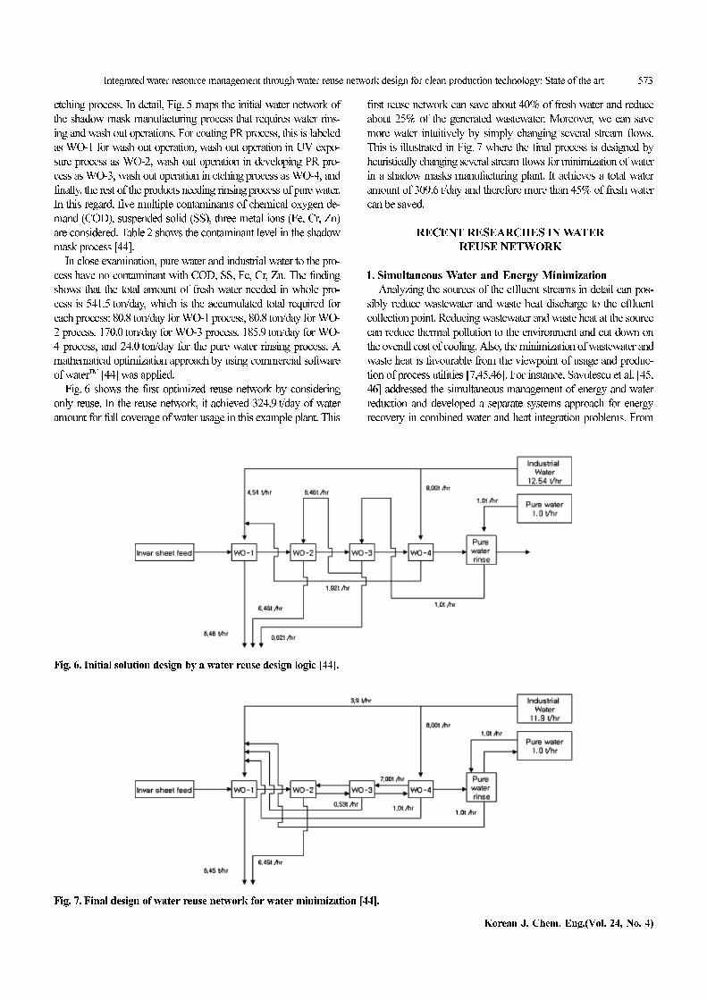
In close examination, pure water and industrial water to the pro-
cess have no contaminant with COD, SS, Fe, Cr, Zn. The finding
shows that the total amount of fresh water needed in whole pro-
cess is 541.5 ton/day, which is the accumulated total required for
each process: 80.8 ton/day for WO-1 process, 80.8 ton/day for WO-
2 process, 170.0 ton/day for WO-3 process, 185.9 ton/day for WO-
4 process, and 24.0 ton/day for the pure water rinsing process. A
mathematical optimization approach by using commercial software
of waterTM [44] was applied.
Fig. 6 shows the first optimized reuse network by considering
only reuse. In the reuse network, it achieved 324.9 t/day of water
amount for full coverage of water usage in this example plant. This
first reuse network can save about 40% of fresh water and reduce
about 25% of the generated wastewater. Moreover, we can save
more water intuitively by simply changing several stream flows.
This is illustrated in Fig. 7 where the final process is designed by
heuristically changing several stream flows for minimization of water
in a shadow masks manufacturing plant. It achieves a total water
amount of 309.6 t/day and therefore more than 45% of fresh water
can be saved.
RECENT RESEARCHES IN WATER
REUSE NETWORK
1. Simultaneous Water and Energy Minimization
Analyzing the sources of the effluent streams in detail can pos-
sibly reduce wastewater and waste heat discharge to the effluent
collection point. Reducing wastewater and waste heat at the source
can reduce thermal pollution to the environment and cut down on
the overall cost of cooling. Also, the minimization of wastewater and
waste heat is favourable from the viewpoint of usage and produc-
tion of process utilities [7,45,46]. For instance, Savulescu et al. [45,
46] addressed the simultaneous management of energy and water
reduction and developed a separate systems approach for energy
recovery in combined water and heat integration problems. From
Fig. 7. Final design of water reuse network for water minimization [44].
Fig. 6. Initial solution design by a water reuse design logic [44].
574 C. Yoo et al.
July, 2007
tematically investigated, including system interactions of water and
energy integration [7].
2. Energy-Pinch Analysis
Water integration studies have focused on reducing the amount
of water used by a process on the assumption that environmental
impact is reduced through efficient water reuse. However, the envi-
ronmental impact of retrofitting a water network through the instal-
lation of pumps and pipes and energy for their utilization, which
may even lead to a network with a higher environmental cost as
measured by using a more comprehensive metric, is rarely, if at all,
considered.
Some papers [38,47,48] show the power of energy analysis and
its ability for simultaneous consideration of different industrial re-
sources, goods and services for the purposes of decision-making.
Accompanied by the pinch concept, which by now tries to deal sep-
arately with each of the resources (energy, water, hydrogen, oxygen,
etc.), the combined energy-pinch analysis provides a wide range of
benefits boosted with extra inside and design guidelines improving
the integration of processes and the ability to consider the ‘past’
and the ‘future’ of the resources (the effort of making them avail-
able and the effort of minimizing their environmental impact). A
theoretical background is presented of the energy and pinch com-
bination into the general resources management technique, which
proves this concept on classical energy and pinch examples accom-
panied with a combined resources management industrial problem
considering the environmental impact of industrial activities [38,47,
48].
Zhelev and Ridolfi [49,50] presented an approach which com-
bines the energy efficiency and the environmental impact of the
selected process. The only way of reducing the environmental im-
pact of a process is through a reduction of its energy usage, which
is feasible by reducing the quantity of raw material (less energy) or
using product with lower transformity such as renewable resources
that have lower level of transformity.
Additionally, Ku-Pineda and Tan [51] address the question on
water integration and environmental impact using the sustainable
process index (SPI) as a means of measuring environmental impact.
This study proposes that optimizing SPI instead of water consump-
tion may eventually provide means of integrating existing water
pinch and process integration principles into a broader clean pro-
duction framework with life-cycle considerations. Moreover, it is
shown that a balance must be achieved between water savings and
water network modifications. Wang et al. [47,48] dealt with the ap-
plication of an energy analysis of an eco-industrial park with a power
plant. Moreover, they suggest several new energy indices and eval-
uate them in consideration of both the material circulation and en-
ergy and water utilization.
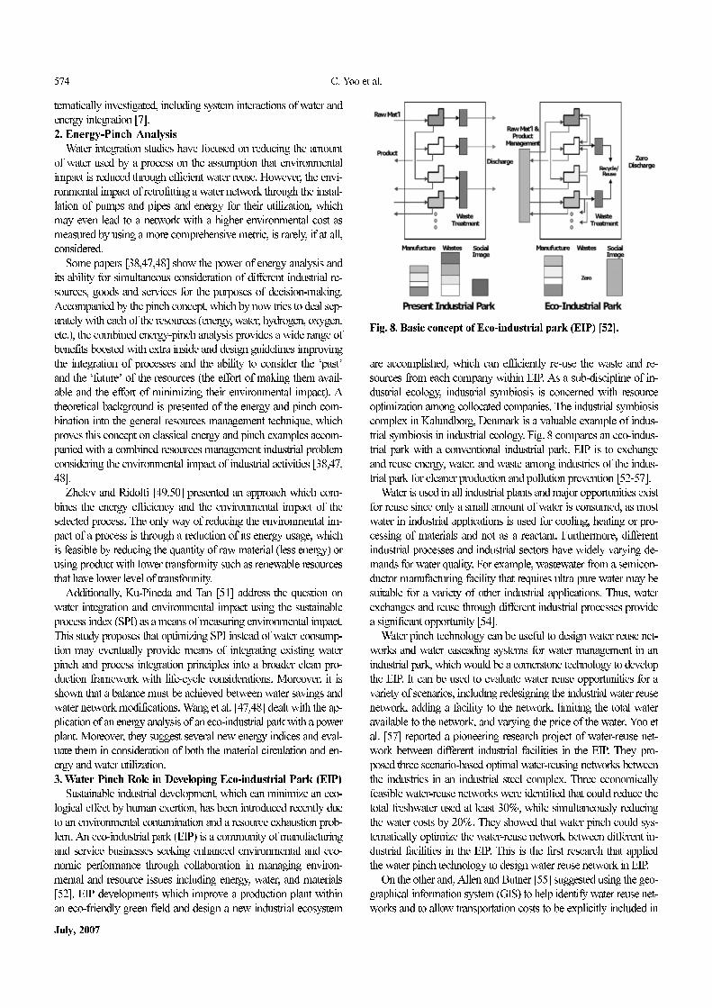
3. Water Pinch Role in Developing Eco-industrial Park (EIP)
Sustainable industrial development, which can minimize an eco-
logical effect by human exertion, has been introduced recently due
to an environmental contamination and a resource exhaustion prob-
lem. An eco-industrial park (EIP) is a community of manufacturing
and service businesses seeking enhanced environmental and eco-
nomic performance through collaboration in managing environ-
mental and resource issues including energy, water, and materials
[52]. EIP developments which improve a production plant within
an eco-friendly green field and design a new industrial ecosystem
are accomplished, which can efficiently re-use the waste and re-
sources from each company within EIP. As a sub-discipline of in-
dustrial ecology, industrial symbiosis is concerned with resource
optimization among collocated companies. The industrial symbiosis
complex in Kalundborg, Denmark is a valuable example of indus-
trial symbiosis in industrial ecology. Fig. 8 compares an eco-indus-
trial park with a conventional industrial park. EIP is to exchange
and reuse energy, water, and waste among industries of the indus-
trial park for cleaner production and pollution prevention [52-57].
Water is used in all industrial plants and major opportunities exist
for reuse since only a small amount of water is consumed, as most
water in industrial applications is used for cooling, heating or pro-
cessing of materials and not as a reactant. Furthermore, different
industrial processes and industrial sectors have widely varying de-
mands for water quality. For example, wastewater from a semicon-
ductor manufacturing facility that requires ultra pure water may be
suitable for a variety of other industrial applications. Thus, water
exchanges and reuse through different industrial processes provide
a significant opportunity [54].
Water pinch technology can be useful to design water reuse net-
works and water cascading systems for water management in an
industrial park, which would be a cornerstone technology to develop
the EIP. It can be used to evaluate water reuse opportunities for a
variety of scenarios, including redesigning the industrial water reuse
network, adding a facility to the network, limiting the total water
available to the network, and varying the price of the water. Yoo et
al. [57] reported a pioneering research project of water-reuse net-
work between different industrial facilities in the EIP. They pro-
posed three scenario-based optimal water-reusing networks between
the industries in an industrial steel complex. Three economically
feasible water-reuse networks were identified that could reduce the
total freshwater used at least 30%, while simultaneously reducing
the water costs by 20%. They showed that water pinch could sys-
tematically optimize the water-reuse network between different in-
dustrial facilities in the EIP. This is the first research that applied
the water pinch technology to design water reuse network in EIP.
On the other and, Allen and Butner [55] suggested using the geo-
graphical information system (GIS) to help identify water reuse net-
works and to allow transportation costs to be explicitly included in
Fig. 8. Basic concept of Eco-industrial park (EIP) [52].
Integrated water resource management through water reuse network design for clean production technology: State of the art 575
Korean J. Chem. Eng.(Vol. 24, No. 4)
the optimization of these industrial waste exchange networks. Using
information from the GIS, the model of water pinch matches waste-
water characteristics of facilities with the feed water requirements
of other facilities in the area. By matching streams with compatible
water quality criteria, the water pinch model identified feasible water
reuse opportunities. A GIS-based tool was used to identify and opti-
mize water reuse and find reuse opportunities within a complex of
approximately 20 different industrial facilities at the Baytown indus-
trial complex. Economically feasible water-reuse networks were
identified that had the potential to reduce the total freshwater used
by more that 90% while simultaneously reducing the water costs
by 20%. This approach using GIS and a mathematical optimization
of water pinch would be valuable for designing an industrial mate-
rial exchange network in the near future.
CONCLUSIONS
Water pinch, which has been shown to be a powerful methodol-
ogy to identify the bottlenecks in water streams, allows for a precise
analysis of a water network. It recognizes the importance of the pro-
cess integration technology in a water reuse system for clean pro-
duction. Collectively, this paper reviews the theory of water and
wastewater minimization (water pinch technology), project works
and application examples in industries, and alternatives in water
reuse networks of stochastic design approaches and water-reusing
network design in batch industries. Furthermore, it introduces sev-
eral recent research topics such as simultaneous water and energy
minimization and energy-pinch analysis. Practical challenges in in-
dustrial applications, such as EIP development are still needed for
integrated water resource management.
ACKNOWLEDGMENT
This work was supported by the Second-Phase of BK (Brain
Korea) 21 project.
REFERENCES
1. N. Takama, T. Kuriyama and T. Umeda, C &CE., 4, 251 (1980).
2. Y. P. Wang and R. Smith, Chem. Eng. Sci., 49(7), 981 (1994).
3. Y. P. Wang and R. Smith, Chem. Eng. Sci., 49(18), 3127( 1994).
4. Y. P. Wang and R. Smith, Trans IChemE, 73(A), 889 (1995).
5. M. Bagajewicz, Comp. Chem. Eng., 24, 2093 (2000).
6. A. S. Deul, Systematic approach to water resource management in
industry, IWA publishing (2002).
7. J. Kim and R. Smith, Proc. of KPSE, 8(1), 369 (2002).
8. P. Lens, P. Wilderer and T. Asano, Water recycling and resource re-
covery in industry, IWA publishing (2002).
9. C. K. Yoo, C. K. Lee, S. K. Heo, I. B. Lee, D. S. Park, Y. W. Kim
and B. K. Song, NICE, 21(1), 65 (2003).
10. R. Karuppiah and I. E. Grossmann, Comput. & Chem. Eng., 30, 650
(2006).
11. S. Bandyopadhyay, M. D. Ghanekar and H. K. Pillai, Ind. Eng.
Chem. Res., 45(15), 5287 (2006).
12. V. R. Dhole, N. Ramchandani, R. A. Tainsh and M. Wasilewski,
Chem. Eng., 100 (1996).
13. R. F. Dunn, and H.Wenzel, Clean Products and Processes, 121(3),
307 (2001).
14. R. F. Dunn, H. Wenzel and M. R. Overcash, Clean Products and
Processes, 121(3), 319 (2001).
15. R. F. Dunn, H. Wenzel, L. Gottrup and J. Kringelum, Clean Prod-
ucts and Processes, 121(3), 330 (2001).
16. V. Lavric, P. Iancu and V. Plesxu, J. Cleaner Production, 13, 1405
(2005).
17. A. R. Eastwood, R. A. Tainsh and G.-J. Fien, Minimizing wastewa-
ter emissions using waterPinchTM analysis, Technical white paper,
Linnhoff March (1998).
18. B. Linhoff and E. Hindmarsh, Chem. Eng. Sci., 38(5), 745 (1983).
19. M. M. El-Halwagi and V. Manousiouthakis, AIChE J., 35(8), 1233
(1989).
20. M. M. El-Halwagi and V. Manousiouthakis, AIChE J., 36(8), 1209
(1990).
21. M. M. El-Halwagi, Pollution prevention through process integra-
tion, Academic pressure (1997).
22. W. J. Kuo and R. Smith, Chem. Eng. Sci., 52(23), 4273 (1997).
23. Y. H. Yang, H. H. Lou and Y. L. Huang, Waste Management, 38(5),
311 (2000).
24. J. G.. Mann and Y. A. Liu, Industrial water reuse and wastewater
minimization, McGraw-Hill (1999).
25. A. Alva-Argaez, A. C. Kokossis and R. Smith, Comp. Chem. Eng.,
22, S741 (1998).
26. S. J. Doyle and R. Smith, Trans. IChemE, 75, 181 (1997).
27. M. Gunaratnam, A. Alva-Argaez, A. C. Kokossis, J. Kim and R.
Smith, Ind. Eng. Chem. Res., 44, 588 (2005).
28. D. Prakotpol and T. Srinophakun, CEP., 43, 203 (2004).
29. A. Garrard and E. S. Fraga, Comp. Chem. Eng., 22(12), 1837 (1998).
30. C. H. Huang, C. T. Chang, H. C. Ling and C. C. Chang, I&EC, 38,
2666 (1999).
31. M. Sakawa, I. Nishizaki and Y. Uemura, European J. Operational
Research, 131, 1 (2001).
32. L. Cheng, E. Subrahmanian and A. W. Westerberg, Comp. & Chem.
Eng., 27, 781 (2003).
33. M. Almató, E. Sanmartí, A. Espuña and L. Puigjaner, Comp. Chem.
Eng., 21, 971 (1997).
34. M. Almató, A. Espuña and L. Puigjaner, Comp. Chem. Eng., 23,
1427 (1999).
35. Y. P. Wang and R. Smith, Trans. IChemE, Part A, 73, 905 (1995).
36. J. Kim and R. Smith, Process Sa. Environ. Prot., 82(5), 238 (2005).
37. B.-H. Li and C.-T. Chang, I&EC, 45(14), 5027 (2006).
38. H. Yang, Y. Li, J. Shen and S. Hu, Ecological Modeling, 160, 13
(2003).
39. Aspen waterTM 12.1, Getting started guide, Aspen tech (2004).
40. Aspen waterTM 12.1, Users guide, Aspen tech (2004).
41. D. S. Park, Y. W. Kim, B. K Song. I. B Lee and C. K. Yoo, J. Korean
Society of Env. Eng., 25(12), 1550 (2003).
42. D. Koufas and T. Retsina, Wat. Sci. Tech., 43(2), 327 (2001).
43. WatertargetTM, User manual, Linhoff march, UK (2004).
44. J. S. Park, Optimal designing for wastewater minimization that occur
in process industry, Master’s thesis, Graduate of Yeungnam Uni-
versity (2004).
45. L. Savulescu, J. Kim and R. Smith, Chem. Eng. Sci., 60(12), 3279
(2005).
46. L. Savulescu, J. Kim and R. Smith, Chem. Eng. Sci., 60(12), 3291
(2005).

576 C. Yoo et al.
July, 2007
47. L. Wang, J. Zhang and W. Ni, 189, 233 (2005).
48. L. Wang, J. Zhang and W. Ni, Resources, Conservation and Recy-
cling, in press (2006).
49. T. K. Zhelev, R. Ridolfi and N. Marchettini, Energy, in press (2006).
50. T. K. Zhelev and R. Ridolfi, Energy, in press (2006).
51. V. Ku-Pineda and R. R. Tan, J. Cleaner Production, 2006 (in press).
52. E. A. Lowe, Eco-industrial park handbook for Asian developing
countries, Asian development bank report (1997).
53. N. B. Jacobsen, J. Industrial Ecology, 10(1-2), 239 (2006).
54. C. K. Yoo, S. K. Heo, D. J. Yoo, S. J. Lee, J. N. Shin, H. D. Chun,
J. K. Moon and I. B. Lee, Korean Chem. Eng. Res., 43, 549 (2005).
55. D. T. Allen and R. S. Butner, CEP Magazine, 40 (2002).
56. G. S. You, J. W. Ahn and G. C. Han, Korean J. Chem. Eng., 23, 237
(2006)
57. C. K. Yoo, J. K. Moon, H. D. Chun and I. B. Lee, Optimization of
water-reusing network between the industries in an eco-industrial
park complex using water pinch technology, in preparation (2007).