Embed Size (px)
Citation preview
PULASKI CONTRACT 8B CONTRACT 054123300
Page 1 of 122
SPECIAL PROVISIONS PULASKI CONTRACT 8B
CONTRACT NO. 054123300 CITY OF JERSEY CITY, HUDSON COUNTY
AUTHORIZATION OF CONTRACT The Contract is authorized by the provisions of Title 27 of the Revised Statutes of New Jersey and supplements thereto.
SPECIFICATIONS TO BE USED The 2019 Standard Specifications for Road and Bridge Construction, of the New Jersey Department of Transportation (Department) as amended herein will govern the construction of this Project and the execution of the Contract.
These Special Provisions consist of the following:
Pages 1 to 122 inclusive.
State wage rates may be obtained from the New Jersey Department of Labor & Workforce Development (Telephone: 609-292-2259) or by accessing the Department of Labor & Workforce Development’s website at https://www.nj.gov/labor/wagehour/wagerate/prevailing_wage_determinations.html. The State wage rates in effect at the time of award are part of this Contract, pursuant to Chapter 150, Laws of 1963 (N.J.S.A. 34:11-56.25 et seq.).
If an employee of the Contractor or subcontractor has been paid a rate of wages less than the prevailing wage, the Department may suspend the Work, and declare the Contractor in default.
The following information is located at the end of these Special Provisions: 1. Small Business Enterprise Utilization on Wholly State Funded Projects. (State Funded Project
Attachment 1) 2. State of New Jersey Equal Employment Opportunity Special Provisions for Wholly State Funded
Projects. (State Funded Project Attachment 2) 3. Requirements for Affirmative Action to Ensure Equal Employment Opportunity on Wholly State Funded
Projects. (State Funded Project Attachment 3) 4. Investigating, Reporting and Resolving Employment Discrimination and Sexual Harassment Complaints on
Wholly State Funded Projects. (State Funded Project Attachment 4) 5. Payroll Requirements for Wholly State Funded Projects. (State Funded Project Attachment 5) 6. Americans with Disabilities Act Requirements for Wholly State Funded Contracts. (State Funded Project
Attachment 6)
The following additional Project specific Attachments are located at the end of these Special Provisions: 7. Railroad Attachments
a. Specifications for Wire, Conduit & Cable Occupations of Consolidated Rail Corporation Property (CE-4) b. Specific Requirements of Consolidated Rail Corporation for Work on Its Right of Way (CE-6) c. Specifications for Pipeline Occupancy of Consolidated Rail Corporation Property (CE-8) d. Entry Permit Application Instructions (Conrail) e. Conrail Submittal Checklists f. Conrail Demolition Track Protection Detail g. PATH Operations and Conditions h. Guidelines for Design of Temporary Protection and/or Hanging Work Platform over PATH Property i. Right of Entry Agreement between PATH and NJDOT
8. Construction Specifications for the Temporary Treatment System 9. Sample Landfill Permit plans

PULASKI CONTRACT 8B CONTRACT 054123300
Page 2 of 122
DIVISION 100 – GENERAL PROVISIONS
SECTION 101 – GENERAL INFORMATION
101.01 INTRODUCTION THE FOLLOWING IS ADDED:
Pursuant to N.J.S.A. 27:1B-21.6, the Department intends to enter into a contract for the advancement of the Project. However, sufficient funds for the Project may not have been appropriated, and only amounts appropriated by law may be expended. Payment under the Contract is restricted to the amounts appropriated for a fiscal year (FY).
Governing bodies have no legal obligation to make such an appropriation. There is no guarantee that additional funds will be appropriated. Failure by governing bodies to appropriate additional funds will not constitute a default under, or a breach of, the Contract. However, if the Department terminates the Contract or suspends work because funds have not been appropriated, the parties to the Contract will retain their rights for suspension and termination as provided in 108.13, 108.14, and 108.15; except as indicated below.
Do not expend or cause to be expended any sum in excess of the amount allocated in the current fiscal year's Capital Program (as specified below). The Department will notify the Contractor when additional funding has been appropriated. Any expenditure by the Contractor which exceeds the amount appropriated is at the Contractor's risk and the Contractor waives its right to recover costs in excess of that appropriated amount.
The Department has $15.0 million available for the construction of the Project during State FY 2021.
The Department anticipates that $50.0 million dollars in additional funds will be provided during State FY 2022.
The Department anticipates that $50.0 million dollars in additional funds will be provided during State FY 2023.
The Department anticipates that the balance of the funds necessary to complete the Project will be provided during State FY 2024.
The State FY begins July 1 of the previous calendar each year.
101.03 TERMS THE FOLLOWING TERM IS ADDED:
Full Traffic Access. All work is complete to allow safe unencumbered use of the final paved portion of roadway throughout the Project including but not limited to striping, RPMs, rumble strips, highway lighting, and traffic signals as determined by the RE.
101.04 INQUIRIES REGARDING THE PROJECT
2. After Award of Contract.
North Region Ms. Chrissa Roessner, Regional Construction Engineer 200 Stierli Court Mt. Arlington, NJ 07856-1322 Telephone: 973-601-6655
SECTION 102 – BIDDING REQUIREMENTS AND CONDITIONS
102.04 EXAMINATION OF CONTRACT AND PROJECT LIMITS
Project Manager: Scott Thorn Email Address: [email protected] Mailing Address: 1035 Parkway Avenue, Trenton, NJ 08625
PULASKI CONTRACT 8B CONTRACT 054123300
Page 3 of 122
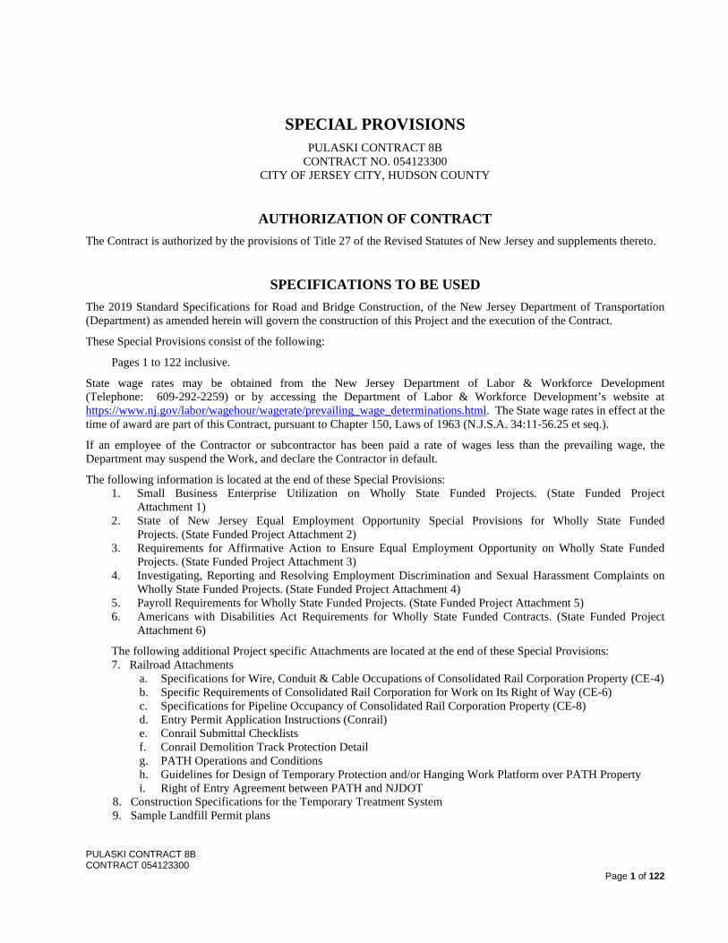
The following is a list of structures and the location(s) of lead paint:
Structure #/Location Lead Paint Location(s) 0901-150 The entire bridge was originally coated with a lead based paint
1. Evaluation of Subsurface and Surface Conditions. THE LAST PARAGRAPH IS CHANGED TO:
NEW JERSEY DEPARTMENT OF TRANSPORTATION
PAVEMENT CORE RECORD PROJECT/ROUTE & SECTION: ___Rehabilitation of Pulaski Skyway (Route U.S. 1&9)______________
DRILLER: _____AHIES, LLC______________________________________________________________
INSPECTOR: ______G. Shen_______________________________________________________________
COUNTY/TOWNSHIP: _____Hudson County, Jersey City______________________________________
DATE STARTED: ___11/13/2014____ DATE COMPLETED: ____11/13/2014_______
CORE
NUMBER ROUTE DIRECTION (N, E, S, W)
MILE POST
or STATION
LANE NO. (Left to Right)
SHOULDER (Inside or Outside)
CORE DIAMETER
(Inches)
TOTAL CORE
DEPTH (Inches)
CORE DRILLED
TO
SURFACE TYPE
(AC/PC)
AC THICKNESS
(Inches)
PC THICKNESS
(Inches)
1
Pulaski Skyway
Broadway Ramp
S 207+74 1 - 4 8.50 Base AC 8.50 0
2
Pulaski Skyway
Broadway Ramp
N 208+06 1 - 4 9.50 Base AC 9.50 0
3
Pulaski Skyway
Broadway Ramp
S 209+91 1 - 4 16.00 Base AC 7.00 9.00
4
Pulaski Skyway
Broadway Ramp
N 209+66 1 - 4 18.00 Base AC 9.00 9.00
5
Pulaski Skyway
Broadway Ramp
S 212+12 1 - 4 13.00 Base AC 3.25 9.75
6
Pulaski Skyway
Broadway Ramp
N 211+98 1 - 4 13.00 Base AC 3.00 10.00
7
Pulaski Skyway
Broadway Ramp
S 214+02 1 - 4 6.75 Base AC 6.75 0
8
Pulaski Skyway
Broadway Ramp
N 213+88 1 - 4 6.25 Base AC 6.25 0
* Lane 1 is the left lane in the direction of travel.
PULASKI CONTRACT 8B CONTRACT 054123300
Page 4 of 122
The pavement information shown herein was used by the Department for design and estimate purposes.
The Bidder may inspect the records of the Department’s investigation of the condition of the substructure concrete through the Department’s Engineering Documents Unit, 1035 Parkway Avenue, P.O. Box 600, Trenton, NJ 08625-0600. The report is titled “SIMCO Pulaski Skyway Substructure Concrete condition assessment and service life evaluation, June 2016”.
3. Existing Plans and As-Builts.
Existing plans including structural plans, contour maps, and as-built plans used are as follows:
a. Original plans for construction of the Pulaski Skyway dated in the 1930’s, in various sections b. Working Drawings for portions of the Pulaski Skyway c. Decking Pulaski Skyway Ramp WELL Rehabilitation of Pulaski Skyway SB – Route 1&9 (1953),
Sec 2 d. General Pulaski Memorial Skyway Safety Improvements – Route 1&9 (1953), Sec 2AB&5H e. General Pulaski Memorial Skyway Rehabilitation – Route 1 Bus (1953), Sec 1K f. General Pulaski Memorial Skyway Rehabilitation – Route 1&9 (1953), Sec 2AH-5J g. Interim Repairs, Contract #1 (Contract No. 051043220) h. Interim Repairs, Contract #2 (Contract No. 051083210) i. Interim Repairs, Contract #3 (Contract No. 051093010) j. Interim Drainage Repairs, Contract #4 (Contract No. 051093830) k. Pulaski Contract No. 1 (Contract No. 054114280) l. Pulaski Contract No. 3 (Contract No. 051123250) m. Pulaski Contract No. 4 (Contract No. 051123260) n. Route 1&9T (25) St. Paul’s Ave. Bridge Contract No. 003970114 o. Route 1&9 Contract No. 049600860 p. Pulaski Contract 7 (Contract No 051123290) q. Route U.S. 1&9 (Pulaski Skyway) Rocker-Bent Investigation Contract (Contract No. 051183160) r. Route U.S. 1&9 (Pulaski Skyway) Contract 5 (Contract No. 051123270) s. Route 1 (1927) Section 5B, Route U.S. 1&9 Truck (1953) t. Route U.S. 1&9 Truck (1953) Section 1L
THE FOLLOWING IS ADDED:
The Bidder shall not assume that all drawings and information related to the original construction of the bridge and any subsequent modifications are available, or that these are a complete or accurate depiction of actual field conditions. The Bidder shall not assume that drawings marked as-built or shop drawings are a representation of actual field conditions.
102.10 SUBMISSION OF BIDS THE FOLLOWING IS ADDED AT THE END OF THE SUBSECTION:
By submitting its bid to the Department, the Bidder warrants that no person or selling agency has been employed or retained by the Bidder to solicit or secure such Contract upon an agreement or understanding for a commission, percentage, brokerage or contingent fee, except bona fide employees or bona fide established commercial or selling agencies maintained by the Bidder for the purpose of securing business, for the breach or violation of which warranty the Department shall have the right to annul such Contract without liability or in its discretion to deduct from the contract price or consideration the full amount of such commission, percentage, brokerage or contingent fee as required by N.J.S.A. 52:34-15.
PULASKI CONTRACT 8B CONTRACT 054123300
Page 5 of 122
SECTION 104 – SCOPE OF WORK
104.02 VALUE ENGINEERING
104.02.01 Purpose and Scope THE FOLLOWING IS ADDED:
The Department will not consider the following as VE Proposal(s):
Micropiles, rocker bent structural steel repairs
SECTION 105 – CONTROL OF WORK
105.05 WORKING DRAWINGS THE LAST SENTENCE IN NINTH PARAGRAPH IS CHANGED TO:
The working drawings submitted for certification are not required to be signed and sealed by a Professional Engineer unless they alter the original Contract or are specified in the Subsection to be signed and sealed.
THE FOLLOWING ARE ADDED TO TABLE 105.05 1:
Certified Approved
Structural Steel (Broadway Ramp) Micropiles
Approach Slab Reinforcement Erection Plan
Steel Repair, Type _____ Demolition Plan
Structural Steel Retrofit, Type_____ Vibration Monitoring
Structural Steel Repairs, Type 1 (RB___)
Exodermic Panels (CIP Concrete)
Ornamental Railing
Steel Bridge Railing
1. Certified Working Drawings. THE LAST SENTENCE OF THE FIRST PARAGRAPH IS CHANGED TO:
The Department will require 45 days for review and certification or rejection and return of certified working drawings related to work on Span 44 and Pier 44. These drawings will also require coordination with the railroad as specified in 105.07.01.
2. Approved Working Drawings. THE LAST SENTENCE OF THE FIRST PARAGRAPH IS CHANGED TO:
The Department will require 65 days for review and approval or rejection and return of working drawings related to work on Span 44 and Pier 44. These drawings will also require coordination with the railroad as specified in 105.07.01.
PULASKI CONTRACT 8B CONTRACT 054123300
Page 6 of 122
105.06 COOPERATION WITH OTHERS
THE FOLLOWING IS ADDED:
Other work that is ongoing near the Project for both the Department and others the Department is cooperating with include: NJDOT Pulaski Skyway, Rocker-Bent Investigation Contract NJDOT Pulaski Skyway Rehab, Contracts 4, 5, 6A, 6B, 7, 8C & 9 NJDOT Route 7, Hackensack River (Whittpenn) Bridge NJTA Contract T100.403 - Bridge Repairs and Resurfacing, Milepost 0 to 122, the NB-HCE, and PHMTE (2018) NJTA Contract T100.436 – Rehabilitation of the NJ Turnpike Passaic River Bridges, Structures W107.87 and E107.88 (2019) NJTA Contract T200.456 - Roadway Resurfacing, Milepost 83 to 122 NJTA Contract T200.457 - Roadway Resurfacing, Milepost 0 to 122 NJTA Contract T200.458 - Concrete Median Barrier Replacement, Milepost 0 to 122 NJTA Various - Installation of Variable Message Signs- New/Existing Locations NJTA Contract T100.321 - Rehabilitation of Structure Nos. N6.49, N6.80E and N6.80W, Milepost N5.80 to N8.20 NJTA Contract T100.381 - Shoulder and Ramp Bridge Deck Reconstruction and Miscellaneous Repairs, NB-HCE, Milepost N0.0 to N6.0 NJTA Contract T100.184 - Bridge Deck Reconstruction, Miscellaneous Structural Improvements, Lighting Improvements, and Repainting Structural Steel, Structure No. N2.01, Newark Bay Bridge, Milepost N 0.00 to N 6.00 NJTA Contract T100.404 - Bridge Repairs and Resurfacing, Milepost 0 to 122, the PHMTE and the NB-HCE (2018) NJTA Contract T600.319 - Roadside Guide Sign Improvements on the New Jersey Turnpike Replacement of Substation #7 PATH. Contact information: 1) Antonio Miranda, PATH, phone: 212-502-2304, email: [email protected]; and Michael Guthy, email: [email protected].
105.07.01 Working in the Vicinity of Utilities
A. Initial Notice.
ELECTRIC Public Service Electric & Gas Co. (Electric) Mr. Charles Miracola 4000 Hadley Road South Plainfield, NJ 07080 T: 908-412-2228 E: [email protected] Mr. John Gahwyler [email protected] T: 908-412-7334 C: 908-208-3728 GAS Public Service Electric & Gas Co. (Gas) Mr. Len Pannucci 4000 Hadley Road South Plainfield, NJ 07080 T: 908-412-2228 E: [email protected]
PULASKI CONTRACT 8B CONTRACT 054123300
Page 7 of 122
Mr. Franky Coriano [email protected] T: 609-743-0006 Fax: 732-919-7854 CABLE TV Comcast Mr. Robert Knoepfel Planning and Design Tech 2 800 Rahway Ave. Union, NJ 07083 T: 908-378-0258 E: [email protected] Fax: 908-378-0256 Altice (formerly Cablevision) Dennis Haney 1111 Stewart Avenue Bethpage, NY 11714 T: 516-803-2300 E: [email protected]
SANITARY Jersey City Municipal Utility Authority (MUA) Mr. Richard Haytas 555 Route 440 Jersey City, NJ 07305 T: 201-432-1150 WATER Jersey City Municipal Utility Authority (MUA) Mr. Richard Haytas 555 Route 440 Jersey City, NJ 07305 T: 201-432-1150 TELECOMMUNICATIONS VERIZON – New Jersey, Inc. (Telecommunications) Frank Antisell 6000 Hadley Road South Plainfield, NJ 07080 T: 908-412-6160 E: [email protected]
Krzysztof Ogrodnik Centralized Engineering T: 908-412-6161 E: Krzysztof. [email protected] SUNESYS (Fiber Optic) Lauren Levitt 3200 Horizon Drive, Suite 150 King of Prussia, PA 19406 T: 610-567-3234 E: [email protected]
PULASKI CONTRACT 8B CONTRACT 054123300
Page 8 of 122
PORT AUTHORITY OF NEW YORK AND NEW JERSEY (COMMUNICATIONS - ITS) Joaquin Gonzalez 4 World Trade Center 150 Greenwich St – 22nd Floor New York, NY 10006 T: 212-435-2144 E: [email protected] RAILROAD FACILITIES Port Authority of New York and New Jersey (PATH) Ken Wallace Superintendent Ways and Structures PATH T: 201-216-6471 E: [email protected] CONRAIL Vincent Milano Consolidated Rail Corporation 1000 Howard Boulevard Mt. Laurel, NJ 08054 T: 856-231-6118 E: [email protected]
B. Locating Existing Facilities.
THE FOLLOWING IS ADDED PRIOR TO THE FIRST SENTENCE OF SUBPART 2:
2. For the Department’s fiber optic network, there are ITS facilities that are under construction as part of other Pulaski Skyway Contracts and may have not been finally accepted. Coordinate with that contractor regarding the location and status of any ITS facilities in the vicinity of the Work. If those ITS facilities are operational, then also coordinate with the contact listed below:
Bureau of Traffic Operations, North Region (TOCN) 670 River Drive Elmwood Park, NJ 07407-1347 Telephone: 732-697-7360
Fiber Optic Markout Form is available at: http://www.state.nj.us/transportation/eng/elec/ITS/requests.shtm.
SUBPART 3 IS CHANGED TO: 3. For the Department’s electrical facilities, obtain the as-built information as specified in 102.04 and contact the
Department as specified below for additional information, de-energizing existing NJDOT electrical facilities, and coordinating the work in the vicinity of Department electrical facilities:
Bureau of Electrical Maintenance, North Region 200 Stierli Court Mt. Arlington, NJ 07856-1322 Telephone: 973-601-6650
C. Protection of Utilities.
Facility Daily Access Request Form is available at:http://www.state.nj.us/transportation/eng/elec/ITS/access.shtm.
PULASKI CONTRACT 8B CONTRACT 054123300
Page 9 of 122
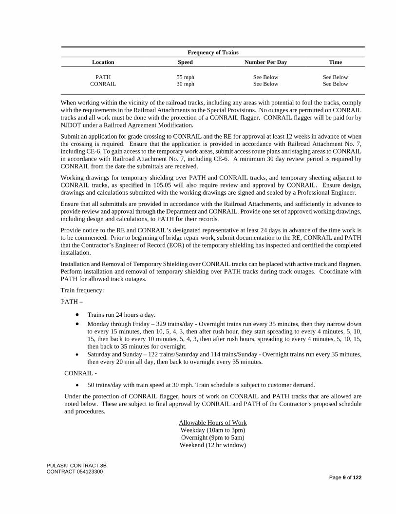
Frequency of Trains
Location Speed Number Per Day Time
PATH CONRAIL
55 mph 30 mph
See Below See Below
See Below See Below
When working within the vicinity of the railroad tracks, including any areas with potential to foul the tracks, comply with the requirements in the Railroad Attachments to the Special Provisions. No outages are permitted on CONRAIL tracks and all work must be done with the protection of a CONRAIL flagger. CONRAIL flagger will be paid for by NJDOT under a Railroad Agreement Modification.
Submit an application for grade crossing to CONRAIL and the RE for approval at least 12 weeks in advance of when the crossing is required. Ensure that the application is provided in accordance with Railroad Attachment No. 7, including CE-6. To gain access to the temporary work areas, submit access route plans and staging areas to CONRAIL in accordance with Railroad Attachment No. 7, including CE-6. A minimum 30 day review period is required by CONRAIL from the date the submittals are received.
Working drawings for temporary shielding over PATH and CONRAIL tracks, and temporary sheeting adjacent to CONRAIL tracks, as specified in 105.05 will also require review and approval by CONRAIL. Ensure design, drawings and calculations submitted with the working drawings are signed and sealed by a Professional Engineer.
Ensure that all submittals are provided in accordance with the Railroad Attachments, and sufficiently in advance to provide review and approval through the Department and CONRAIL. Provide one set of approved working drawings, including design and calculations, to PATH for their records.
Provide notice to the RE and CONRAIL’s designated representative at least 24 days in advance of the time work is to be commenced. Prior to beginning of bridge repair work, submit documentation to the RE, CONRAIL and PATH that the Contractor’s Engineer of Record (EOR) of the temporary shielding has inspected and certified the completed installation.
Installation and Removal of Temporary Shielding over CONRAIL tracks can be placed with active track and flagmen. Perform installation and removal of temporary shielding over PATH tracks during track outages. Coordinate with PATH for allowed track outages.
Train frequency:
PATH –
• Trains run 24 hours a day. • Monday through Friday – 329 trains/day - Overnight trains run every 35 minutes, then they narrow down
to every 15 minutes, then 10, 5, 4, 3, then after rush hour, they start spreading to every 4 minutes, 5, 10, 15, then back to every 10 minutes, 5, 4, 3, then after rush hours, spreading to every 4 minutes, 5, 10, 15, then back to 35 minutes for overnight.
• Saturday and Sunday – 122 trains/Saturday and 114 trains/Sunday - Overnight trains run every 35 minutes, then every 20 min all day, then back to overnight every 35 minutes.
CONRAIL -
• 50 trains/day with train speed at 30 mph. Train schedule is subject to customer demand.
Under the protection of CONRAIL flagger, hours of work on CONRAIL and PATH tracks that are allowed are noted below. These are subject to final approval by CONRAIL and PATH of the Contractor’s proposed schedule and procedures.
Allowable Hours of Work Weekday (10am to 3pm) Overnight (9pm to 5am)
Weekend (12 hr window)
PULASKI CONTRACT 8B CONTRACT 054123300
Page 10 of 122
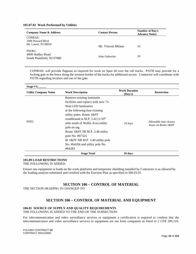
105.07.02 Work Performed by Utilities
Company Name & Address Contact Person Number of Day/s Advance Notice
CONRAIL 1000 Howard Blvd Mt. Laurel, NJ 08054 PSE&G 4000 Hadley Road South Plainfield, NJ 07080
Mr. Vincent Milano John Gahwyler
24 30
CONRAIL will provide flagman as required for work on Span 44 over the rail tracks. PATH may provide for a locking gate in the fence along the western border of the tracks for additional access. Contractor will coordinate with PATH regarding location and use of the gate.
Stage # 6______
Utility Company Name Work Description Work Duration (Day/s) Restriction
PSEG
Remove existing luminaire facilities and replace with new 73-Watt LED luminaires at the following four existing utility poles: Route 1&9T southbound at M.P. 3.42 (1/10th mile south of Wallis Ave) utility pole no tag Route 1&9T SB M.P. 3.40 utility pole No. #67324 Rt 1&9T NB M.P. 3.40 utility pole No. #64284 and utility pole No. #64283
10 days Allowable lane closure hours on Route 1&9T
Stage Total 10 days
105.09 LOAD RESTRICTIONS THE FOLLOWING IS ADDED:
Ensure any equipment or loads on the work platforms and temporary shielding installed by Contractor is as allowed by the loading analysis submitted and certified with the Erection Plan as specified in 506.03.01.
SECTION 106 – CONTROL OF MATERIAL THE SECTION HEADING IS CHANGED TO:
SECTION 106 – CONTROL OF MATERIAL AND EQUIPMENT
106.01 SOURCE OF SUPPLY AND QUALITY REQUIREMENTS THE FOLLOWING IS ADDED TO THE END OF THE SUBSECTION:
For telecommunication and video surveillance services or equipment a certification is required to confirm that the telecommunication and video surveillance services or equipment are not from companies as listed in 2 CFR 200.216.
PULASKI CONTRACT 8B CONTRACT 054123300
Page 11 of 122
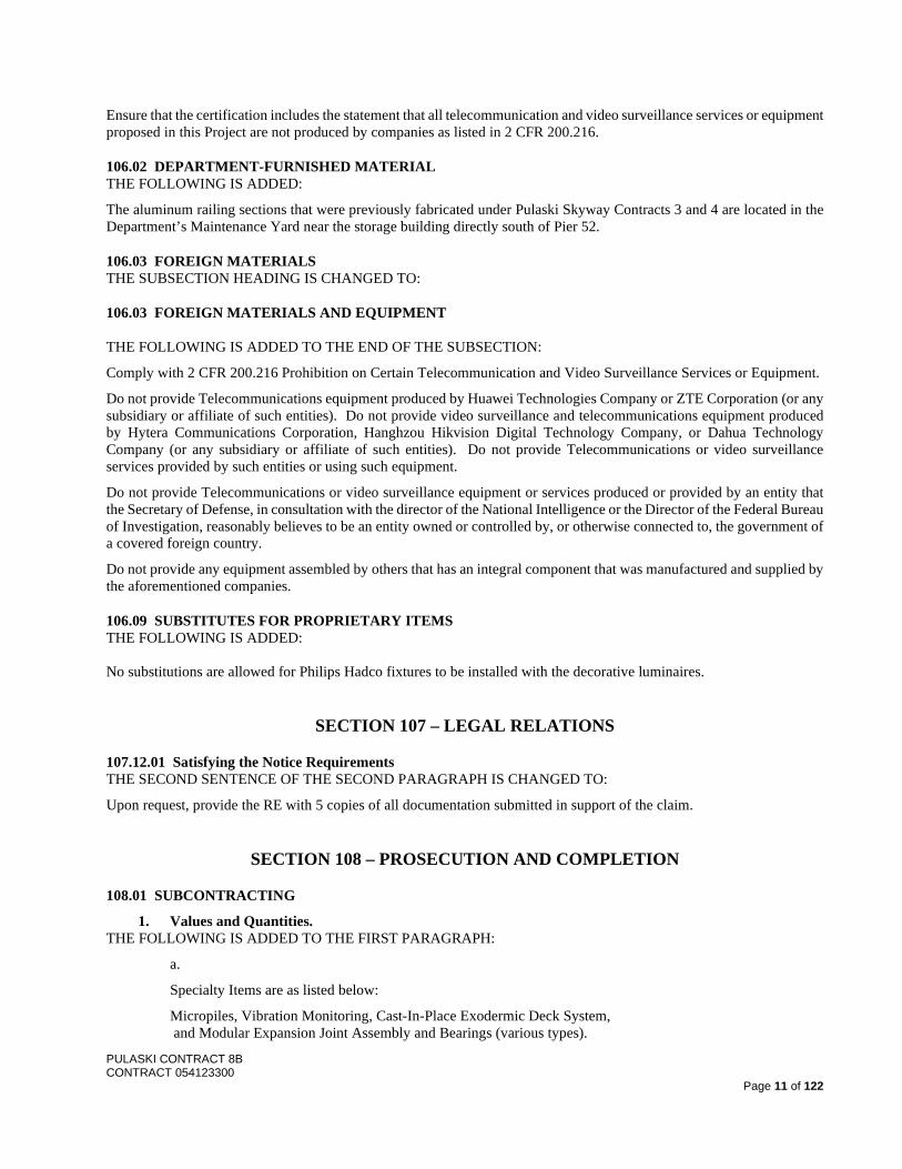
Ensure that the certification includes the statement that all telecommunication and video surveillance services or equipment proposed in this Project are not produced by companies as listed in 2 CFR 200.216.
106.02 DEPARTMENT-FURNISHED MATERIAL THE FOLLOWING IS ADDED:
The aluminum railing sections that were previously fabricated under Pulaski Skyway Contracts 3 and 4 are located in the Department’s Maintenance Yard near the storage building directly south of Pier 52.
106.03 FOREIGN MATERIALS THE SUBSECTION HEADING IS CHANGED TO:
106.03 FOREIGN MATERIALS AND EQUIPMENT THE FOLLOWING IS ADDED TO THE END OF THE SUBSECTION:
Comply with 2 CFR 200.216 Prohibition on Certain Telecommunication and Video Surveillance Services or Equipment.
Do not provide Telecommunications equipment produced by Huawei Technologies Company or ZTE Corporation (or any subsidiary or affiliate of such entities). Do not provide video surveillance and telecommunications equipment produced by Hytera Communications Corporation, Hanghzou Hikvision Digital Technology Company, or Dahua Technology Company (or any subsidiary or affiliate of such entities). Do not provide Telecommunications or video surveillance services provided by such entities or using such equipment.
Do not provide Telecommunications or video surveillance equipment or services produced or provided by an entity that the Secretary of Defense, in consultation with the director of the National Intelligence or the Director of the Federal Bureau of Investigation, reasonably believes to be an entity owned or controlled by, or otherwise connected to, the government of a covered foreign country.
Do not provide any equipment assembled by others that has an integral component that was manufactured and supplied by the aforementioned companies.
106.09 SUBSTITUTES FOR PROPRIETARY ITEMS THE FOLLOWING IS ADDED: No substitutions are allowed for Philips Hadco fixtures to be installed with the decorative luminaires.
SECTION 107 – LEGAL RELATIONS
107.12.01 Satisfying the Notice Requirements THE SECOND SENTENCE OF THE SECOND PARAGRAPH IS CHANGED TO:
Upon request, provide the RE with 5 copies of all documentation submitted in support of the claim.
SECTION 108 – PROSECUTION AND COMPLETION
108.01 SUBCONTRACTING
1. Values and Quantities. THE FOLLOWING IS ADDED TO THE FIRST PARAGRAPH:
a.
Specialty Items are as listed below:
Micropiles, Vibration Monitoring, Cast-In-Place Exodermic Deck System, and Modular Expansion Joint Assembly and Bearings (various types).
PULASKI CONTRACT 8B CONTRACT 054123300
Page 12 of 122
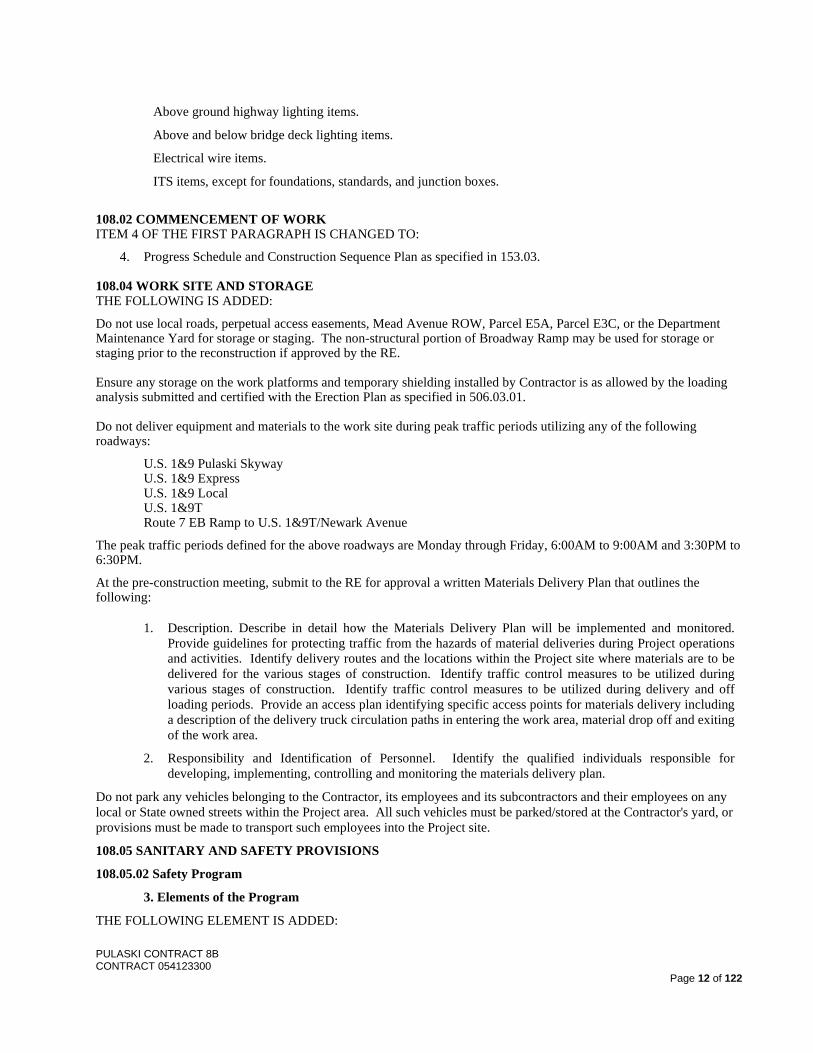
Above ground highway lighting items.
Above and below bridge deck lighting items.
Electrical wire items.
ITS items, except for foundations, standards, and junction boxes.
108.02 COMMENCEMENT OF WORK ITEM 4 OF THE FIRST PARAGRAPH IS CHANGED TO:
4. Progress Schedule and Construction Sequence Plan as specified in 153.03. 108.04 WORK SITE AND STORAGE THE FOLLOWING IS ADDED:
Do not use local roads, perpetual access easements, Mead Avenue ROW, Parcel E5A, Parcel E3C, or the Department Maintenance Yard for storage or staging. The non-structural portion of Broadway Ramp may be used for storage or staging prior to the reconstruction if approved by the RE. Ensure any storage on the work platforms and temporary shielding installed by Contractor is as allowed by the loading analysis submitted and certified with the Erection Plan as specified in 506.03.01. Do not deliver equipment and materials to the work site during peak traffic periods utilizing any of the following roadways:
U.S. 1&9 Pulaski Skyway U.S. 1&9 Express U.S. 1&9 Local U.S. 1&9T Route 7 EB Ramp to U.S. 1&9T/Newark Avenue
The peak traffic periods defined for the above roadways are Monday through Friday, 6:00AM to 9:00AM and 3:30PM to 6:30PM.
At the pre-construction meeting, submit to the RE for approval a written Materials Delivery Plan that outlines the following:
1. Description. Describe in detail how the Materials Delivery Plan will be implemented and monitored. Provide guidelines for protecting traffic from the hazards of material deliveries during Project operations and activities. Identify delivery routes and the locations within the Project site where materials are to be delivered for the various stages of construction. Identify traffic control measures to be utilized during various stages of construction. Identify traffic control measures to be utilized during delivery and off loading periods. Provide an access plan identifying specific access points for materials delivery including a description of the delivery truck circulation paths in entering the work area, material drop off and exiting of the work area.
2. Responsibility and Identification of Personnel. Identify the qualified individuals responsible for developing, implementing, controlling and monitoring the materials delivery plan.
Do not park any vehicles belonging to the Contractor, its employees and its subcontractors and their employees on any local or State owned streets within the Project area. All such vehicles must be parked/stored at the Contractor's yard, or provisions must be made to transport such employees into the Project site.
108.05 SANITARY AND SAFETY PROVISIONS
108.05.02 Safety Program
3. Elements of the Program
THE FOLLOWING ELEMENT IS ADDED:
PULASKI CONTRACT 8B CONTRACT 054123300
Page 13 of 122
n. Contractor Access Plan. Provide a plan detailing how and where the contractor's personnel will gain access to the work site including parking locations and entry points to each work area. Provide guidelines for protecting staff in entering and exiting the work area.
108.07 TRAFFIC CONTROL
108.07.01 Interference THE FOLLOWING IS ADDED TO THE FOURTH PARAGRAPH:
Coordinate and provide delivery access to the businesses located at Block 9103 Lots 2 and 3 adjacent to Mead Avenue ROW. Access to these businesses is only permitted through the use Mead Avenue ROW and properties South of the Pulaski Skyway.
108.08 LANE OCCUPANCY CHARGES SUBSECTION IS RENAMED AND CHANGED TO:
108.08 OCCUPANCY CHARGES
The closure schedule shown in the plans indicates the time periods for allowable closures as specified in the Contract. Allowable closures are permitted for, but not limited to; roadways, lanes, shoulders and ramps. If the Contractor’s closures exceed these time periods, the Department will deduct from the monthly estimate an occupancy charge for the use and occupancy beyond the time periods shown in the closure schedule until such time that the closure is reopened to traffic or until such time that the closure is allowed to take place again under the closure schedule. The Department will recover the cost of occupancy charges as specified in 107.16.
The RE will keep record of each occurrence as well as the cumulative amount of time that a closure exceeds the time periods shown in the closure schedule and provide the record to the Contractor. The Department will calculate an occupancy charge by multiplying the length of time of each delayed opening, in minutes, by the rate of $10 per minute, unless otherwise specified in the Special Provisions. The total amount per day for occupancy charges that the Department will collect will not exceed $10,000.00.
The Department will waive an occupancy charge where a closure is not reopened to traffic as specified in the closure schedule directly and solely by reason of extraordinary, exigent circumstances not under the control of or reasonably foreseeable by the Contractor. Equipment breakdowns, supplier deliveries, and weather related hindrances are not extraordinary, exigent circumstances. However, the Department has the right to assess an occupancy charge for any period of time that a closure remains closed beyond the reasonable period of time needed by the Contractor to reopen a closure due to an extraordinary, exigent circumstance.
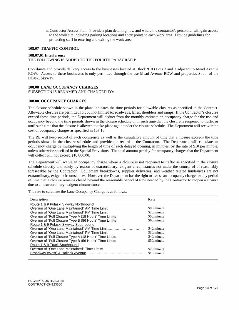
The rate to calculate the Lane Occupancy Charge is as follows:
Description Rate Route 1 & 9 Pulaski Skyway Northbound Overrun of "One Lane Maintained" AM Time Limit Overrun of "One Lane Maintained" PM Time Limit Overrun of "Full Closure Type A (18 Hour)" Time Limits Overrun of "Full Closure Type B (56 Hour)" Time Limits Route 1 & 9 Pulaski Skyway Southbound Overrun of "One Lane Maintained" AM Time Limit…………………………. Overrun of "One Lane Maintained" PM Time Limit Overrun of "Full Closure Type A (18 Hour)" Time Limits Overrun of "Full Closure Type B (56 Hour)" Time Limits Route 1 & 9 Truck Southbound Overrun of "One Lane Maintained" Time Limits Broadway (West) & Halleck Avenue………………………………………… .
$90/minute $20/minute $50/minute $60/minute $40/minute $30/minute $40/minute $50/minute
$20/minute $10/minute
PULASKI CONTRACT 8B CONTRACT 054123300
Page 14 of 122
108.10 CONTRACT TIME
A. Complete all work required for Interim Completion for Stage 1 through 4 on or before September 16, 2024.
B. Complete all work required for Substantial Completion on or before July 31, 2025.
C. Achieve Completion on or before October 30, 2025.
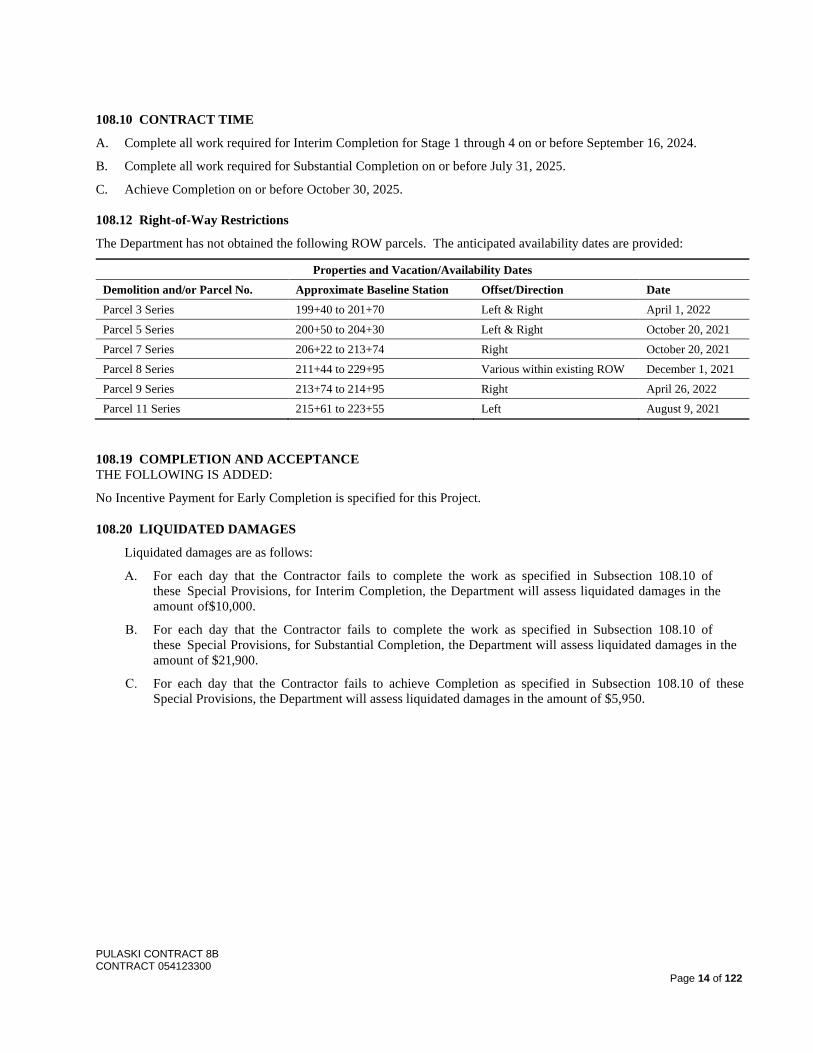
108.12 Right-of-Way Restrictions
The Department has not obtained the following ROW parcels. The anticipated availability dates are provided:
Properties and Vacation/Availability Dates Demolition and/or Parcel No. Approximate Baseline Station Offset/Direction Date Parcel 3 Series 199+40 to 201+70 Left & Right April 1, 2022
Parcel 5 Series 200+50 to 204+30 Left & Right October 20, 2021 Parcel 7 Series 206+22 to 213+74 Right October 20, 2021 Parcel 8 Series 211+44 to 229+95 Various within existing ROW December 1, 2021 Parcel 9 Series 213+74 to 214+95 Right April 26, 2022 Parcel 11 Series 215+61 to 223+55 Left August 9, 2021
108.19 COMPLETION AND ACCEPTANCE THE FOLLOWING IS ADDED:
No Incentive Payment for Early Completion is specified for this Project.
108.20 LIQUIDATED DAMAGES
Liquidated damages are as follows:
A. For each day that the Contractor fails to complete the work as specified in Subsection 108.10 of these Special Provisions, for Interim Completion, the Department will assess liquidated damages in the amount of$10,000.
B. For each day that the Contractor fails to complete the work as specified in Subsection 108.10 of these Special Provisions, for Substantial Completion, the Department will assess liquidated damages in the amount of $21,900.
C. For each day that the Contractor fails to achieve Completion as specified in Subsection 108.10 of these Special Provisions, the Department will assess liquidated damages in the amount of $5,950.
PULASKI CONTRACT 8B CONTRACT 054123300
Page 15 of 122
SECTION 109 – MEASUREMENT AND PAYMENT
109.05 ESTIMATES THE FOURTH PARAGRAPH IS CHANGED TO:
The RE will provide a summary of the Estimate to the Contractor. Before the issuance of each payment, certify, on forms provided by the Department, whether:
A. Intentionally left blank.
B. On State Funded Projects 1. No subcontractor or supplier was used on the Project; or 2. Each subcontractor and supplier used on the Project has been paid the amount due, excluding retainage, from the previous progress payment and will be paid the amount due from the current progress payment, excluding retainage, for the subcontractor or supplier’s work that was paid by the Department; or 3. There exists a valid basis under the terms of the subcontractor’s or supplier’s contract to withhold payments from the subcontractor or supplier. Therefore, the following subcontractors and suppliers have not been paid for work performed or materials supplied to the Project from the proceeds of the previous progress payment or will not be paid for work performed or materials supplied to this Project from the proceeds of the current progress payment, or both.
PULASKI CONTRACT 8B CONTRACT 054123300
Page 16 of 122
DIVISION 150 – CONTRACT REQUIREMENTS
SECTION 152 – INSURANCE
152.03.01 Railroad Protective Liability Insurance
Procure and maintain insurance coverage for the following railroad(s):
Consolidated Rail Corporation (CONRAIL) PATH/Port Authority of New York and New Jersey (PANYNJ)
It is estimated that 7.5% percent of the Project cost is located within or adjacent to the railroad ROW.
SECTION 153 – PROGRESS SCHEDULE
153.01 DESCRIPTION THE FOLLOWING IS ADDED:
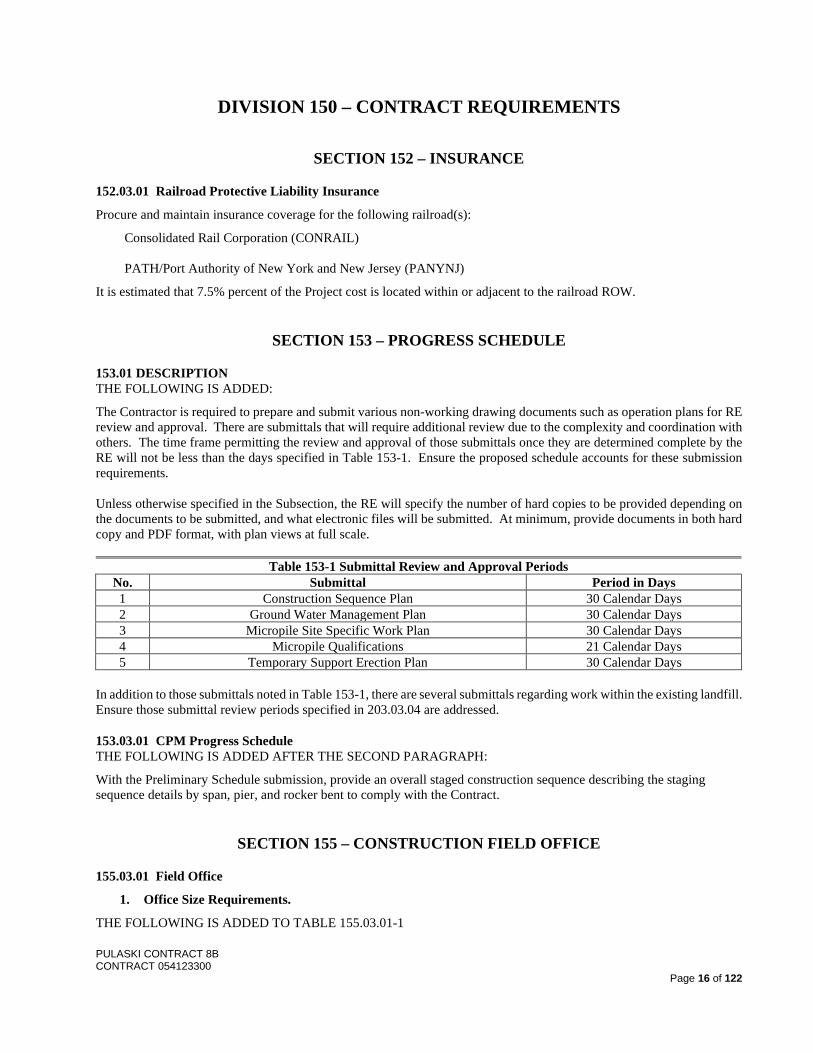
The Contractor is required to prepare and submit various non-working drawing documents such as operation plans for RE review and approval. There are submittals that will require additional review due to the complexity and coordination with others. The time frame permitting the review and approval of those submittals once they are determined complete by the RE will not be less than the days specified in Table 153-1. Ensure the proposed schedule accounts for these submission requirements. Unless otherwise specified in the Subsection, the RE will specify the number of hard copies to be provided depending on the documents to be submitted, and what electronic files will be submitted. At minimum, provide documents in both hard copy and PDF format, with plan views at full scale.
Table 153-1 Submittal Review and Approval Periods No. Submittal Period in Days 1 Construction Sequence Plan 30 Calendar Days 2 Ground Water Management Plan 30 Calendar Days 3 Micropile Site Specific Work Plan 30 Calendar Days 4 Micropile Qualifications 21 Calendar Days 5 Temporary Support Erection Plan 30 Calendar Days
In addition to those submittals noted in Table 153-1, there are several submittals regarding work within the existing landfill. Ensure those submittal review periods specified in 203.03.04 are addressed.
153.03.01 CPM Progress Schedule THE FOLLOWING IS ADDED AFTER THE SECOND PARAGRAPH:
With the Preliminary Schedule submission, provide an overall staged construction sequence describing the staging sequence details by span, pier, and rocker bent to comply with the Contract.
SECTION 155 – CONSTRUCTION FIELD OFFICE
155.03.01 Field Office
1. Office Size Requirements.
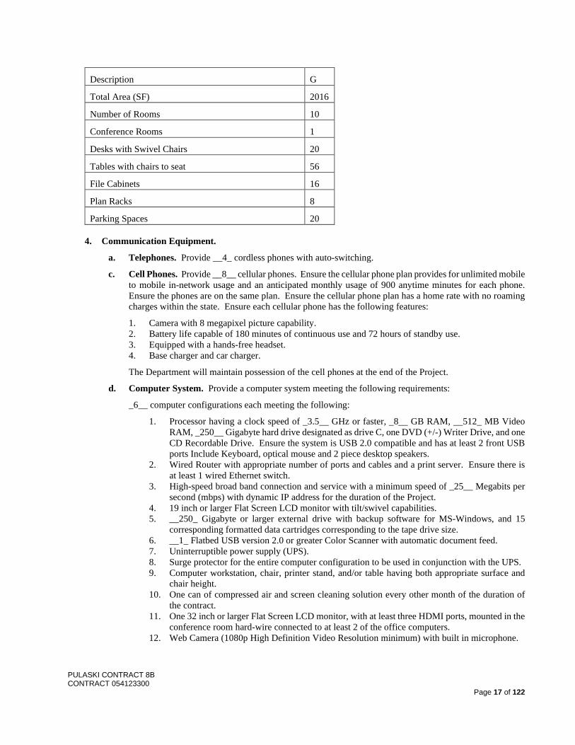
THE FOLLOWING IS ADDED TO TABLE 155.03.01-1
PULASKI CONTRACT 8B CONTRACT 054123300
Page 17 of 122
Description G
Total Area (SF) 2016
Number of Rooms 10
Conference Rooms 1
Desks with Swivel Chairs 20
Tables with chairs to seat 56
File Cabinets 16
Plan Racks 8
Parking Spaces 20
4. Communication Equipment.
a. Telephones. Provide __4_ cordless phones with auto-switching.
c. Cell Phones. Provide __8__ cellular phones. Ensure the cellular phone plan provides for unlimited mobile to mobile in-network usage and an anticipated monthly usage of 900 anytime minutes for each phone. Ensure the phones are on the same plan. Ensure the cellular phone plan has a home rate with no roaming charges within the state. Ensure each cellular phone has the following features:
1. Camera with 8 megapixel picture capability. 2. Battery life capable of 180 minutes of continuous use and 72 hours of standby use. 3. Equipped with a hands-free headset. 4. Base charger and car charger.
The Department will maintain possession of the cell phones at the end of the Project.
d. Computer System. Provide a computer system meeting the following requirements:
_6__ computer configurations each meeting the following:
1. Processor having a clock speed of _3.5__ GHz or faster, _8__ GB RAM, __512_ MB Video RAM, _250__ Gigabyte hard drive designated as drive C, one DVD (+/-) Writer Drive, and one CD Recordable Drive. Ensure the system is USB 2.0 compatible and has at least 2 front USB ports Include Keyboard, optical mouse and 2 piece desktop speakers.
2. Wired Router with appropriate number of ports and cables and a print server. Ensure there is at least 1 wired Ethernet switch.
3. High-speed broad band connection and service with a minimum speed of _25__ Megabits per second (mbps) with dynamic IP address for the duration of the Project.
4. 19 inch or larger Flat Screen LCD monitor with tilt/swivel capabilities. 5. __250_ Gigabyte or larger external drive with backup software for MS-Windows, and 15
corresponding formatted data cartridges corresponding to the tape drive size. 6. __1_ Flatbed USB version 2.0 or greater Color Scanner with automatic document feed. 7. Uninterruptible power supply (UPS). 8. Surge protector for the entire computer configuration to be used in conjunction with the UPS. 9. Computer workstation, chair, printer stand, and/or table having both appropriate surface and
chair height. 10. One can of compressed air and screen cleaning solution every other month of the duration of
the contract. 11. One 32 inch or larger Flat Screen LCD monitor, with at least three HDMI ports, mounted in the
conference room hard-wire connected to at least 2 of the office computers. 12. Web Camera (1080p High Definition Video Resolution minimum) with built in microphone.
PULASKI CONTRACT 8B CONTRACT 054123300
Page 18 of 122
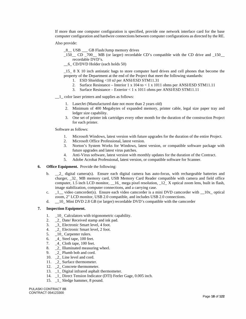
If more than one computer configuration is specified, provide one network interface card for the base computer configuration and hardwire connections between computer configurations as directed by the RE.
Also provide:
_8__ USB ___ GB Flash/Jump memory drives _150__ CD _700__ MB (or larger) recordable CD’s compatible with the CD drive and _150__
recordable DVD’s. __6_ CD/DVD Holder (each holds 50)
_15_ 8 X 10 inch antistatic bags to store computer hard drives and cell phones that become the property of the Department at the end of the Project that meet the following standards:
1. ESD Shielding <10 nJ per ANSI/ESD STM11.31 2. Surface Resistance – Interior 1 x 10⁴ to < 1 x 10¹¹ ohms per ANSI/ESD STM11.11 3. Surface Resistance – Exterior < 1 x 10¹¹ ohms per ANSI/ESD STM11.11
__1_ color laser printers and supplies as follows:
1. LaserJet (Manufactured date not more than 2 years old) 2. Minimum of 400 Megabytes of expanded memory, printer cable, legal size paper tray and
ledger size capability. 3. One set of printer ink cartridges every other month for the duration of the construction Project
for each printer.
Software as follows:
1. Microsoft Windows, latest version with future upgrades for the duration of the entire Project. 2. Microsoft Office Professional, latest version. 3. Norton’s System Works for Windows, latest version, or compatible software package with
future upgrades and latest virus patches. 4. Anti-Virus software, latest version with monthly updates for the duration of the Contract. 5. Adobe Acrobat Professional, latest version, or compatible software for Scanner.
6. Office Equipment. Provide the following:
b. __2_ digital camera(s). Ensure each digital camera has auto-focus, with rechargeable batteries and charger, _32_ MB memory card, USB Memory Card Reader compatible with camera and field office computer, 1.5 inch LCD monitor, __16_ mega pixel resolution, _12_ X optical zoom lens, built in flash, image stabilization, computer connections, and a carrying case.
c. _1__ video camcorder(s). Ensure each video camcorder is a mini DVD camcorder with __10x_ optical zoom, 2" LCD monitor, USB 2.0 compatible, and includes USB 2.0 connections.
d. __10_ Mini DVD 2.8 GB (or larger) recordable DVD’s compatible with the camcorder
7. Inspection Equipment.
1. _10_ Calculators with trigonometric capability. 2. _2_ Date/ Received stamp and ink pad. 3. _3_ Electronic Smart level, 4 foot. 4. _2_ Electronic Smart level, 2 foot. 5. _10_ Carpenter rulers. 6. _4_ Steel tape, 100 feet. 7. _4_ Cloth tape, 100 feet. 8. _2_ Illuminated measuring wheel. 9. _2_ Plumb bob and cord. 10. _2_ Line level and cord. 11. _2_ Surface thermometer. 12. _2_ Concrete thermometer. 13. _1_ Digital infrared asphalt thermometer. 14. _1_ Direct Tension Indicator (DTI) Feeler Gage, 0.005 inch. 15. _1_ Sledge hammer, 8 pound.
PULASKI CONTRACT 8B CONTRACT 054123300
Page 19 of 122
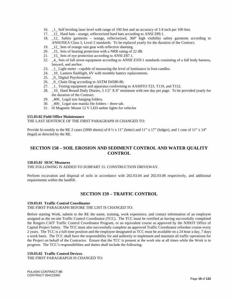
16. _1_ Self leveling laser level with range of 100 feet and an accuracy of 1/4 inch per 100 feet. 17. _12_ Hard hats - orange, reflectorized hard hats according to ANSI Z89.1. 18. _12_ Safety garments – orange, reflectorized, 360º high visibility safety garments according to
ANSI/ISEA Class 3, Level 2 standards. To be replaced yearly for the duration of the Contract. 19. _12_ Sets of orange rain gear with reflective sheeting. 20. _15_ Sets of hearing protection with a NRR rating of 22 dB. 21. _15_ Sets of eye protection according to ANSI Z87.1. 22. _4_ Sets of fall arrest equipment according to ANSII Z359.1 standards consisting of a full body harness,
lanyard, and anchor. 23. _1_ Light meter - capable of measuring the level of luminance in foot-candles. 24. _10_ Lantern flashlight, 6V with monthly battery replacements. 25. _0_ Digital Psychrometer. 26. _0_ Chain Drag according to ASTM D4580-86. 27. _1_ Testing equipment and apparatus conforming to AASHTO T23, T119, and T152. 28. _10_ Hard Bound Daily Diaries, 5 1/2" X 8" minimum with one day per page. To be provided yearly for
the duration of the Contract. 29. _400_ Legal size hanging folders. 30. _400_ Legal size manila file folders – three tab. 31. 10 Magnetic Mount 12 V LED amber lights for vehicles
155.03.02 Field Office Maintenance THE LAST SENTENCE OF THE FIRST PARAGRAPH IS CHANGED TO: Provide bi-weekly to the RE 2 cases (5000 sheets) of 8 ½ x 11” (letter) and 11” x 17” (ledger), and 1 case of 11” x 14” (legal) as directed by the RE.
SECTION 158 – SOIL EROSION AND SEDIMENT CONTROL AND WATER QUALITY CONTROL
158.03.02 SESC Measures THE FOLLOWING IS ADDED TO SUBPART 15. CONSTRUCTION DRIVEWAY. Perform excavation and disposal of soils in accordance with 202.03.04 and 202.03.08 respectively, and additional requirements within the landfill.
SECTION 159 – TRAFFIC CONTROL
159.03.01 Traffic Control Coordinator THE FIRST PARAGRAPH BEFORE THE LIST IS CHANGED TO:
Before starting Work, submit to the RE the name, training, work experience, and contact information of an employee assigned as the on-site Traffic Control Coordinator (TCC). The TCC must be certified as having successfully completed the Rutgers CAIT Traffic Control Coordinator Program, or an equivalent course as approved by the NJDOT Office of Capital Project Safety. The TCC must also successfully complete an approved Traffic Coordinator refresher course every 2 years. The TCC is a full-time position and the employee designated as TCC must be available on a 24 hour a day, 7 days a week basis. The TCC shall have the responsibility for and authority to implement and maintain all traffic operations for the Project on behalf of the Contractor. Ensure that the TCC is present at the work site at all times while the Work is in progress. The TCC’s responsibilities and duties shall include the following:
159.03.02 Traffic Control Devices THE FIRST PARAGRAPGH IS CHANGED TO:
PULASKI CONTRACT 8B CONTRACT 054123300
Page 20 of 122
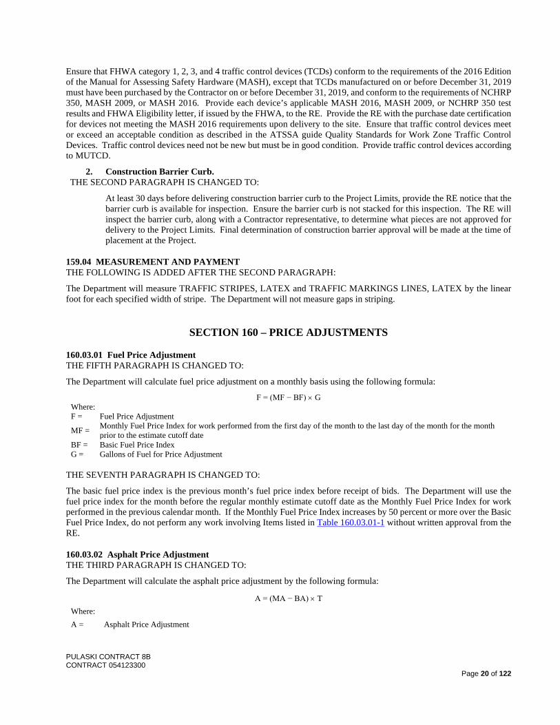
Ensure that FHWA category 1, 2, 3, and 4 traffic control devices (TCDs) conform to the requirements of the 2016 Edition of the Manual for Assessing Safety Hardware (MASH), except that TCDs manufactured on or before December 31, 2019 must have been purchased by the Contractor on or before December 31, 2019, and conform to the requirements of NCHRP 350, MASH 2009, or MASH 2016. Provide each device’s applicable MASH 2016, MASH 2009, or NCHRP 350 test results and FHWA Eligibility letter, if issued by the FHWA, to the RE. Provide the RE with the purchase date certification for devices not meeting the MASH 2016 requirements upon delivery to the site. Ensure that traffic control devices meet or exceed an acceptable condition as described in the ATSSA guide Quality Standards for Work Zone Traffic Control Devices. Traffic control devices need not be new but must be in good condition. Provide traffic control devices according to MUTCD.
2. Construction Barrier Curb. THE SECOND PARAGRAPH IS CHANGED TO:
At least 30 days before delivering construction barrier curb to the Project Limits, provide the RE notice that the barrier curb is available for inspection. Ensure the barrier curb is not stacked for this inspection. The RE will inspect the barrier curb, along with a Contractor representative, to determine what pieces are not approved for delivery to the Project Limits. Final determination of construction barrier approval will be made at the time of placement at the Project.
159.04 MEASUREMENT AND PAYMENT THE FOLLOWING IS ADDED AFTER THE SECOND PARAGRAPH:
The Department will measure TRAFFIC STRIPES, LATEX and TRAFFIC MARKINGS LINES, LATEX by the linear foot for each specified width of stripe. The Department will not measure gaps in striping.
SECTION 160 – PRICE ADJUSTMENTS
160.03.01 Fuel Price Adjustment THE FIFTH PARAGRAPH IS CHANGED TO:
The Department will calculate fuel price adjustment on a monthly basis using the following formula:
F = (MF − BF) × G Where: F = Fuel Price Adjustment
MF = Monthly Fuel Price Index for work performed from the first day of the month to the last day of the month for the month prior to the estimate cutoff date
BF = Basic Fuel Price Index G = Gallons of Fuel for Price Adjustment
THE SEVENTH PARAGRAPH IS CHANGED TO:
The basic fuel price index is the previous month’s fuel price index before receipt of bids. The Department will use the fuel price index for the month before the regular monthly estimate cutoff date as the Monthly Fuel Price Index for work performed in the previous calendar month. If the Monthly Fuel Price Index increases by 50 percent or more over the Basic Fuel Price Index, do not perform any work involving Items listed in Table 160.03.01-1 without written approval from the RE.
160.03.02 Asphalt Price Adjustment THE THIRD PARAGRAPH IS CHANGED TO:
The Department will calculate the asphalt price adjustment by the following formula:
A = (MA − BA) × T Where: A = Asphalt Price Adjustment
PULASKI CONTRACT 8B CONTRACT 054123300
Page 21 of 122
MA = Monthly Asphalt Price Index for work performed from the first day of the month to the last day of the month for the month prior to the estimate cutoff date
BA = Basic Asphalt Price Index T = Tons of New Asphalt Binder1 1. The Department will determine the weight of asphalt binder for price adjustment by multiplying the percentage of new asphalt
binder in the approved job mix formula by the weight of the item containing asphalt binder. If a Hot Mix Asphalt Item has a payment unit other than ton, the Department will apply an appropriate conversion factor to determine the number of tons of asphalt binder used.
THE SIXTH PARAGRAPH IS CHANGED TO:
The basic asphalt price index is the asphalt price index for the month before the opening of bids. The Department will use the asphalt price index for the month before the regular monthly estimate cutoff date as the monthly asphalt price index for work performed in the previous calendar month.
THE FOLLOWING SECTION IS ADDED:
SECTION 162 – VIBRATION MONITORING
162.01 DESCRIPTION
This Section describes the requirements for performing the pre-construction, construction, and post-construction inspection surveys and monitoring of vibration levels, movement, settlement and stress-stain-temperature conditions during construction operations. Perform monitoring during demolition, excavation, pile and sheeting installation, jacking for truss rehabilitation and bearing replacement, and any other construction activity directed by the RE that may have significant impact on existing or newly constructed structures.
162.02 EQUIPMENT
Provide instruments and devices as required to complete the monitoring. Ensure equipment is suitable for bridge structures and construction site applications, and provides for the following at minimum:
1. Resistant to UV light 2. Water and moisture proof to IP66 minimum 3. NEMA Type 4X for all enclosures 4. Anti-tamper or other vandalism protection features
Conduct regular maintenance and protect all components of monitoring instrumentation from damage. Store and maintain back-up replacement equipment and materials on site to expedite any required repairs or replacements. Notify the RE immediately of damaged or inoperative instruments. Repair or replace damaged or inoperative instruments within 48 hours. Notify the RE at least 24 hours before repairing or replacing a damaged or inoperative instrument. The RE will be the sole judge of whether repair or replacement is required. The RE may impose a work stoppage in the vicinity of the damaged or inoperative instrument until it is repaired or replaced to the satisfaction of the RE.
Conduct a factory calibration on all instruments prior to delivery to the site and throughout construction as needed. Provide certification, dated within the previous 6 months, to indicate that the test equipment is calibrated and maintained according to the test equipment manufacturer’s calibration requirements and that, where applicable, calibrations are traceable to the National Institute of Standards and Technology. Include the certifications in the working drawing submittals.
Store all instrumentation materials, after receipt at the site, in an indoor, clean, dry, and secure storage space where they will not suffer physical damage or damage arising from excessive moisture, temperature extremes, or other adverse conditions. Do not expose instruments to temperatures outside the manufacturer’s stated working temperature range. When instruments are received at the site, perform pre-installation acceptance tests to ensure that the instruments and readout units are functioning correctly before installation. Provide the RE with copies of the completed tests.
Ensure the proposed power supply provides 24/7 power service (minimum 15 amp, 110/220V AC) to cover all sensors shown on the Plans, proposed by the Contractor, or as directed by the RE, and meeting surge protection and other requirements by the instrumentation manufacturer. Provide sufficient battery backup for minimum 48 hour service. Provide generator service if power outages extend past 48 hours. Provide separate master cabinets for the monitoring specified under 162.03.01 and 162.03.02, each with a minimum 1 TB storage.
PULASKI CONTRACT 8B CONTRACT 054123300
Page 22 of 122
The Department may allow service to be obtained from an existing load center if approved by the RE. Maintain the load center for the duration of the Contract.
162.03 INSTALLATION
162.03.01 Vibration Induced Movement and Settlement
A. Equipment. Provide prisms for the survey markers to be set as per the requirements of the Contract.
Provide seismographs, accurate to 0.01 in/sec, with a built-in tri-axial transducer containing three geophones located along orthogonal axes (vertical, longitudinal, and transverse) capable of continuously measuring and recording the peak particle velocities at the 3 axes of ground vibration. Provide seismographs that have a visual readout for real-time monitoring. Ensure that seismographs are capable of automatic email notification of exceedance of a preset threshold value for at least 4 email addresses. At a minimum, send automatic notification emails to the vibration specialist, the RE, and two personnel from the Department’s designated Design Unit. Provide a certificate of calibration, dated within the previous 6 months of its use on the Project and traceable to the National Institute of Standards and Technology, to the RE for approval for each seismograph.
Provide bi-axial tiltmeters, accurate to 0.001 degrees, with continuous monitoring and off-site data storage where the data collected can be monitored in real time. Record ambient temperature at each location and reported graphically vs. time with bi-axial tiltmeter rotation data. Provide a certificate of calibration to the RE for approval, dated within the previous 6 months of its use on the Project for each bi-axial tiltmeters.
Provide mechanical displacement gauges, accurate to 0.001 inches. Provide certificate of calibration performed within 6 months of their installation on the Project.
Provide survey equipment to 1st order accuracy.
B. Pre-approval Procedure. Perform all work and prepare reports and plans under the direct supervision of a Professional Engineer. Ensure that the Professional Engineer has at least 5 years of responsible experience in similar work and has attained professional-level capability in geotechnical and structural evaluation and engineering. Perform survey under the direct supervision of a land surveyor. Ensure that the land surveyor has at least 3 years of responsible experience in similar work and is capable of horizontal and vertical monitoring of survey targets, field control points, operating, reading, and interpreting survey instrumentation data for the purpose of evaluating horizontal, vertical and rotational deformations and movement. Perform monitoring under the direct supervision of a vibration specialist. Ensure that the vibration specialist has at least 5 years of responsible experience in similar work and is capable of installing, operating, reading, and interpreting seismographs for the purpose of monitoring vibrations. Ensure that the qualifications of the land surveyor and vibration specialist include at least 3 previous projects for which similar reporting and plan preparation services were provided for monitoring structures, facilities, and utilities.
At least 45 days before commencing the pre-construction and initial survey and monitoring, submit working drawings for approval that describe the vibration monitoring and settlement/movement control plan. Provide figures, sketches, plots, graphs, material descriptions, instrumentation list, proposed vibration and settlement/movement monitoring procedures at each monitoring location, schedule of equipment installation and maintenance, and the proposed locations of survey targets and seismographs. Ensure the plan includes the following:
1. Resumes of the Professional Engineer, land surveyor, vibration specialist, and field engineers and inspectors in sufficient detail that clearly describes their relevant experience and qualifications. Provide 3 references for the Professional Engineer.
2. Resumes of other instrumentation personnel. 3. The locations of the survey targets for movement and settlement monitoring. 4. The locations of seismographs for vibration monitoring. 5. The locations of mechanical displacement gauges for movement monitoring. 6. The locations of bi-axial tiltmeters for rotation/movement monitoring. 7. Manufacturer’s data for vibration, movement, and settlement monitoring instrumentation and equipment. 8. Copy of the factory calibration, the manufacturer’s test equipment certification, and a completed quality
assurance checklist. 9. Warranty for each portable readout unit. 10. Detailed step-by-step installation procedure. 11. Sample installation record form.
PULASKI CONTRACT 8B CONTRACT 054123300
Page 23 of 122
12. Instrumentation/equipment manufacturer’s stated accuracy and the Contractor’s proposed field procedures for ensuring that the measured and recorded data meets the specified accuracies at a 95 percent level of confidence.
13. Schedule of the proposed time sequence of instrumentation installation. 14. Schedule of the proposed monitoring and reporting frequencies for all vibration and settlement monitoring
instruments. 15. Plan of action with corrective action measures in case the vibration or settlement/movement warning
threshold values are exceeded. 16. Description of the maintenance and protection of traffic needs for installation, monitoring and maintenance
of the system. 17. Description of the of back-up power, equipment and materials that will be stored on-site for repair or
replacement as needed to maintain the system in continuous operation.
Ensure that schedules for installation and monitoring address the staging sequences shown on the Plans and the requirements specified herein. Provide a separate submission for work related to Span 44 and Pier 44. These require review and approval by CONRAIL, and CONRAIL may require additional monitoring criteria based on Contractor’s proposed temporary sheeting.
Verify the validity of initial instrumentation readings and sign an agreement to such readings in a format approved by the RE. No instrument data will be accepted until the signed agreements are accepted by the RE.
Within 10 days of delivery to the site and installation of each instrument, submit to the RE the following:
1. Completed pre-installation acceptance test record form for that instrument. 2. Completed installation record form for that instrument, including the surveyed as-built instrument location.
Do not disclose vibration instrumentation or settlement data to third parties. Do not publish related data except as specified herein.
C. Pre-construction and Initial Survey and Monitoring. Perform a pre-construction survey of all existing structures and above ground utility/electrical facilities within the monitoring zone, which extends at least 100 feet from all testing or production micropiles, locations of jacking for truss rehabilitation or truss bearing replacement, demolition, excavation, and sheet pile driving. Coordinate with the RE to gain entry to private properties if required. Record the detail and dimensions of all existing cracks, spalls, exposed rebar, evidence of settlement, damage and structural deficiencies. Make notes and sketches indicating the existing condition of the structures and above ground utility/electrical facilities, and record other information as required to assess vibration, movement and settlement susceptibility. Perform both video and photographic documentation of the existing structures and above ground utility/electrical facilities and take close up photos and video of existing conditions and damage.
At least 20 days before performing vibration-producing construction activities, submit 3 copies of the pre-construction survey and vibration monitoring report to the RE on 8-1/2 × 11-inch sheets for approval. Include an index, the names and responsibilities of the inspection team and survey party, field notes, preconstruction survey documentation, videos in minimum MP4 format, video logs, sketches, and 4 × 6-inch color photographs with date and location captions documenting the observed existing conditions. Ensure that the report includes the proposed seismograph and survey target locations as shown on the approved working drawings. Include the ambient baseline vibration, rotation, and settlement readings for the existing structures and utilities. The survey target locations on proposed features are exempt from this submittal. Include an electronic spreadsheet file with the tabulated vibration monitoring data and full waveform plots of the seismograph data. Interpret the ambient baseline data and provide conclusions on ambient vibration levels (preferred average measure) at each seismograph location based on root-mean square (RMS) amplitudes or other appropriate method to establish the applicable baseline ambient vibration level recommendation for future comparison. The purpose of the pre-construction inspection survey and vibration monitoring is to document existing conditions and establish ambient baseline measurements related to potential vibration impacts and movement. Ensure that the scope and detail of the inspection survey and report is sufficient to serve as a reference for comparison should evidence of damage or movement be observed during construction operations.
At least 5 days before the start of monitoring equipment installation the RE will schedule a review meeting including, Geotechnical Engineering, designated design units, and other Department representatives, the prime Contractor, and
PULASKI CONTRACT 8B CONTRACT 054123300
Page 24 of 122
monitoring Subcontractor, including the Professional Engineer. Registered Land Surveyor, and instrumentation supervisor. Attendance is mandatory.
Locate survey targets at the following locations along Pier 44 to Pier 57: 1. One at the top of each column, including the following:
a. For the survey targets at Pier 44 and 45, install the survey targets after all pier strengthening and prior to jacking for bearing replacement. Keep survey targets at Pier 45 in place until the completion of the Span 45 rocker bent reconstruction work. Survey Targets at Pier 44 can be removed after bearing replacement is completed at Pier 44 and bridge lowered.
b. For the survey targets at Pier 46 to 57, install survey targets as close to the top of pier as possible and outside the limits of the proposed pier cap construction.
c. Survey targets must remain in place until all rocker bent reconstruction, pier cap reconstruction, and bearing replacement is completed in the adjacent spans or at that pier.
2. Two at each temporary micropile foundation: Placed at opposite corners of the pile cap such that differential movement and rotation can be monitored for each pile cap. Survey targets to remain in place until the rocker bent reconstruction is complete and bridge lowered to original position.
3. Survey targets located on the truss superstructure and temporary shoring towers as shown on the Plans. Survey targets to remain in place until the rocker bent reconstruction is complete and bridge lowered to original position.
4. A minimum of one at existing structures and above ground utility/electrical facilities within the monitoring zone, which extends at least 100 feet from all testing or production micropiles, locations of jacking for truss rehabilitation or truss bearing replacement, demolition, excavation, and sheet pile driving. Survey targets to remain in place until all work in the monitoring zone is complete.
5. A minimum of two survey targets located on the temporary sheeting that retains the Conrail embankment at Pier 44. Obtain a “zero” measurement prior to commencing excavation within the temporary sheeting. Survey targets to remain in place until the excavation is backfilled and the sheeting removed.
Install the survey target prisms at the truss superstructure locations shown on the Plans in a manner that does not adversely impact the structure.
Monitor movement and settlement at each survey target location for a period of 24 hours after establishing survey target locations to determine baseline coordinates. Document the horizontal coordinates and elevation in feet using the Project vertical and horizontal datum. Establish the survey target baseline coordinates to 0.01 feet and elevation to 0.01 feet using second-order accuracy.
For the temporary micropile foundations, place survey targets and perform 24-hour monitoring after the pile cap has been erected and prior to applying load to the pile cap. No settlement or movement is expected prior to erecting the temporary shoring tower and transferring loads from the superstructure to the temporary pile cap through jacking; if there is any movement notify the RE immediately. However, once load is transferred to the temporary pile caps, vertical settlement is anticipated. Monitor movement and settlement at each temporary pile cap survey target for a second 24-hour period after the superstructure jacks are locked off and all superstructure load is transferred to the temporary pile caps. Do not perform work on the superstructure during this 24-hour monitoring period. At the end of the second 24-hour monitoring period, establish baseline coordinates and elevations for the temporary micropile foundations. Base the warning and action thresholds in Table 162.03.01-2 for the temporary micropile foundations on these baseline coordinates and elevations, established after all superstructure load has been transferred to the temporary supports, for the remainder of construction until the temporary supports are dismantled.
Monitor vibrations at each approved seismograph location for a continuous period of 5 days after installation of vibration monitoring equipment to establish baseline readings. Protect the seismograph from damage. No micropile construction, demolition, excavation, or other vibration inducing operations as determined by the RE, may be performed during this 5-day period.

PULASKI CONTRACT 8B CONTRACT 054123300
Page 25 of 122
Locate seismographs at the following locations along Pier 44 to Pier 57: 1. One at each pier located at the ground level. 2. A minimum of one at existing structures within the monitoring zone, which extends at least 100 feet from all
testing or production micropiles, locations of jacking for truss rehabilitation or truss bearing replacement, demolition, excavation, and sheet pile driving.
Locate mechanical displacement gauges, as shown on the approved temporary support working drawings. Ensure that there are enough gauges to monitor all vertical movement of existing, temporary, or proposed structural features prior to, during, and after jacking operations up until the bridge has been lowered and securely fastened to its original or final proposed position.
Bi-axial tiltmeters are also required if the Contractor’s proposed the use of the Down the Hole Hammer (DTHH) is approved by the RE for micropile installation. See Section 502 for additional information. Provide to the RE a minimum of 1 week of bi-axial tiltmeter readings performed prior to the start of micropile installation to establish baseline readings.
Locate tiltmeters at the following locations:
1. Two at each Pier located on the eastern face of the outermost columns nearest to the rocker bent (RB) Reconstruction (i.e. Pier 46 for RB45, Pier 50 for RB49, Pier 52 for RB51, Pier 54 for RB53, and Pier 56 for RB55).
2. A minimum of one at existing structures within the monitoring zone, which extends at least 100 feet from all test and production micropiles.
D. Vibration Monitoring Movement and Settlement Control. Visually monitor all existing structures, facilities, and utilities within the monitoring zone during construction activities. Perform seismograph monitoring from commencement of any micropiles, sheet piling or other potential vibration-inducing construction until all micropiles and sheet piling have been installed and approved by the RE. Perform movement and settlement monitoring according to the approved plan from commencement of construction operations to completion of construction operations. Ensure that the on-site vibration specialist evaluates each seismograph full-time on the first day of operations, once daily thereafter during vibration inducing construction activities, and twice weekly during the remaining duration of construction until the seismographs are removed.
Ensure that the land surveyor surveys each movement and settlement monitoring target vertically and horizontally in accordance with the construction staging sequence shown on the Plans and as follows:
1. 24 hours prior to jacking the temporary supports into place. 2. After each interval of the jacking sequence for each temporary support as shown on the Plans.
The next jacking interval is subject to RE’s review and acceptance of the data. 3. After jacking is completed to establish new baseline. 4. As specified in the staging sequence per each work location, including at least twice a week after
jacking is completed until Substantial Completion, or as directed by the RE.
Record data in United States customary units. Document the horizontal coordinates and elevation in feet using the Project vertical and horizontal datum. Establish the survey target coordinates to 0.01 feet and elevation to 0.01 feet using second-order accuracy. Ensure that the personnel specified in 162.03.01.A receive an automatic email alert upon exceedance of the warning threshold. Notify the RE at least 24 hours before starting a new vibration-inducing construction task.
Record mechanical displacement gauge readings before jacking, at each jacking interval, and after the jacking operation to transfer load to the jacks. Record gauge readings twice daily, at the beginning and end of each day thereafter. Record gauge readings before, during and after jacking operations to transfer the load to the bearings. Record all gauge readings in the presence of the RE.
Submit updates to the plan to the RE for approval as necessary to reflect new information or changing conditions that may affect vibrations, movement or settlement of structures or facilities. Submit a revised vibration monitoring, movement and settlement control plan to the RE for approval before the start of each major stage, and upon all major changes in work schedule, construction methods, or equipment operations or upon determination that additions or
PULASKI CONTRACT 8B CONTRACT 054123300
Page 26 of 122
adjustments to vibration monitoring, movement and settlement control methods are necessary. When response actions are required as specified herein, or adjustments in vibration monitoring, movement and settlement control methods are required, immediately provide additional vibration, movement and settlement monitoring and control and submit a revised vibration monitoring, movement and settlement control plan documenting the response actions undertaken and the reasons the adjustments are required, making reference to the vibration, movement and settlement monitoring data.
Submit a vibration monitoring, movement and settlement control report to the RE monthly documenting vibration, movement and settlement monitoring performed the previous month. Include:
1. Descriptions of construction locations and operations with activity times and durations. 2. Data plots for each instrument with the threshold values indicated. 3. Unusual events that may have affected the measurements. 4. Descriptions of all response actions or precautionary measures, including the reasons and times that the
response actions were implemented. 5. A description of future response actions or precautionary measures that are planned in response to current
monitoring data. 6. Include daily field logs for vibration and movement monitoring that address: Project name, Contract name
and number, instrument type, date and time, observer, readout unit number, instrument number and location, readings, remarks, visual observations, and other data including weather, temperature, and construction operations.
For all data submitted to the RE, report all raw and reduced data on summary tables in printed tabular format on 8 1/2 × 11 inch sheets in a format approved by the RE. Submit electronic files of the summary tables. Also submit to the RE electronic spreadsheets in a format approved by the RE of vibration monitoring waveform plots and corresponding data.
The Department will use the peak particle velocity threshold values in Table 162.03.01-1 to evaluate the effects of vibration-producing construction activities, except Figure 162.03-1 will be used for work at Pier 44.
PULASKI CONTRACT 8B CONTRACT 054123300
Page 27 of 122
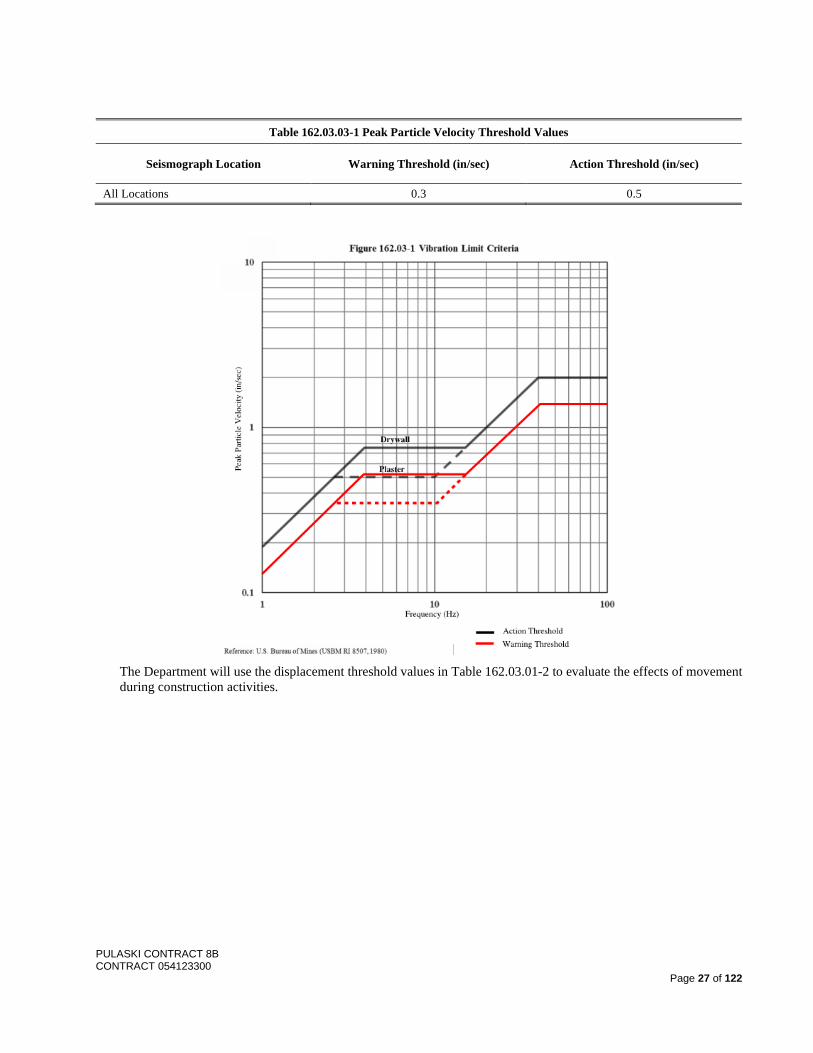
Table 162.03.03-1 Peak Particle Velocity Threshold Values
Seismograph Location Warning Threshold (in/sec) Action Threshold (in/sec)
All Locations 0.3 0.5
The Department will use the displacement threshold values in Table 162.03.01-2 to evaluate the effects of movement during construction activities.
PULASKI CONTRACT 8B CONTRACT 054123300
Page 28 of 122
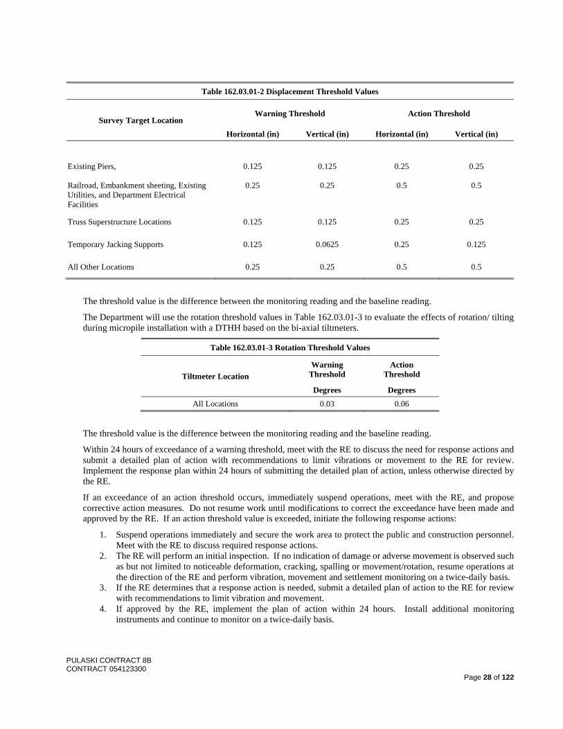
Table 162.03.01-2 Displacement Threshold Values
Survey Target Location Warning Threshold Action Threshold
Horizontal (in) Vertical (in) Horizontal (in) Vertical (in) Existing Piers, Railroad, Embankment sheeting, Existing Utilities, and Department Electrical Facilities
0.125
0.25
0.125
0.25
0.25
0.5
0.25
0.5
Truss Superstructure Locations 0.125 0.125 0.25 0.25
Temporary Jacking Supports 0.125 0.0625 0.25 0.125
All Other Locations 0.25 0.25 0.5 0.5
The threshold value is the difference between the monitoring reading and the baseline reading.
The Department will use the rotation threshold values in Table 162.03.01-3 to evaluate the effects of rotation/ tilting during micropile installation with a DTHH based on the bi-axial tiltmeters.
Table 162.03.01-3 Rotation Threshold Values
Tiltmeter Location Warning
Threshold Action
Threshold
Degrees Degrees All Locations 0.03 0.06
The threshold value is the difference between the monitoring reading and the baseline reading.
Within 24 hours of exceedance of a warning threshold, meet with the RE to discuss the need for response actions and submit a detailed plan of action with recommendations to limit vibrations or movement to the RE for review. Implement the response plan within 24 hours of submitting the detailed plan of action, unless otherwise directed by the RE.
If an exceedance of an action threshold occurs, immediately suspend operations, meet with the RE, and propose corrective action measures. Do not resume work until modifications to correct the exceedance have been made and approved by the RE. If an action threshold value is exceeded, initiate the following response actions:
1. Suspend operations immediately and secure the work area to protect the public and construction personnel. Meet with the RE to discuss required response actions.
2. The RE will perform an initial inspection. If no indication of damage or adverse movement is observed such as but not limited to noticeable deformation, cracking, spalling or movement/rotation, resume operations at the direction of the RE and perform vibration, movement and settlement monitoring on a twice-daily basis.
3. If the RE determines that a response action is needed, submit a detailed plan of action to the RE for review with recommendations to limit vibration and movement.
4. If approved by the RE, implement the plan of action within 24 hours. Install additional monitoring instruments and continue to monitor on a twice-daily basis.
PULASKI CONTRACT 8B CONTRACT 054123300
Page 29 of 122
For instruments that have been installed to replace damaged instruments, use the initial reading from the damaged instrument as an initial reading for the replacement instrument so that data are plotted continuously, without an offset at the time of equipment replacement. Note the time of damage and replacement on the plot.
The vibration specialist is responsible for interpreting the monitoring data to determine appropriate response actions and propose modifications to construction operations. The RE has the right to interpret vibration, movement and settlement data.
E. Post-construction Survey. After completion of construction activities at each location, perform a post-construction survey of all existing structures and utilities within the monitoring zone in the same manner as the pre-construction survey. Perform an additional post-construction survey at Substantial Completion.
Within 10 days of completion of construction activities, submit 3 copies of the final vibration and movement monitoring report of the monitored locations in the same format and with the same type of information as the pre-construction survey and monitoring report. Include all data and findings of the vibration, movement and settlement monitoring program in the report. Document all changes, damage or lack of change or damage to all locations, and submit a repair plan for approval to the RE. Complete repairs to the satisfaction of the RE. Include all 4 × 6-inch color photographs with date and location captions. Submit digital files of all photographs with the report.
After completion of the final report and as directed by the RE, remove all equipment and materials associated with vibration and movement monitoring and restore to preconstruction conditions or as directed by the RE.
162.03.02. Structural Component Monitoring
A. Equipment and System. Provide sensors types that have been successfully used on at least 3 Department or other transportation agencies within the tri-state region on complex bridge projects in the past 5 years, and in systems where measurements are displayed on-site in real time and available through a web-based interface. Provide sensors and a system that meets the following, but not limited, to:
1. Strain gauges with resolutions of +/- 1 microstrain. 2. Temperature gauges that measure the structural members and the ambient air temperature. 3. Safe for in-service use and under inclement and severe weather conditions. 4. Ability to capture data for static (one sample per minute) and dynamic monitoring at 50Hz (samples per
second) simultaneously. 5. Data quality is free of noise induced spikes and temperature compensated as per sensor manufacturer’s
recommendations. 6. Provide for sampling and decimation rates that are adjustable to accommodate the latest conditions or as
directed by the RE, or that the Department can modify the rate both on-site and through the web-based interface.
7. Strain and temperature data is recorded continuously without interruption with backup to an offsite server 8. Data is accessible on site, from both PC and mobile devices, as well as remotely via a web-based interface
to designated Department representatives. 9. Provide for sending alerts at multiple levels (warning, alarm, critical, etc.).
For pre-construction, post-construction, and non-critical construction activity measurements, ensure the decimated rate is not greater than 5 minute intervals with a maximum 30 minute delay for display to be available onsite and remotely via web-based interface. During critical construction activities, ensure real-time for on-site display with a decimated rate no more than 1 minute and no more than a 10 minute delay for on-site and web display. Web display results may contain only decimated data showing the minimum/maximum average over the decimated period. Ensure the system is monitored in real-time and automatically sends out alerts to the Superintendent and RE via SMS text messages and/or emails when pre-defined thresholds for strain/stress values are exceeded at any time. Adjust the sampling or decimated rate as directed by the RE. The Department will advise the RE when the Department has modified the rates.
B. Preapprovals and Monitoring Procedures. Perform all work under the direct supervision of a Professional Engineer. The Professional Engineer must have at least 10 years responsible experience in structural health monitoring with at least 5 projects related to structural evaluations and engineering of steel bridges, and 3 of the projects having durations of at least 12 months each. Other personnel completing the monitoring must have at least 5 years of experience in structural health monitoring.
PULASKI CONTRACT 8B CONTRACT 054123300
Page 30 of 122
Do not disclose gauge data to third parties. Do not publish related data except as specified herein.
At least 90 days before commencing the monitoring, submit comprehensive working drawings, including procedures, for approval that describe the monitoring plan in detail. Provide technical specifications, figures, drawings, plots, graphs, material descriptions, instrumentation list with back-up and spare equipment, procedures, and schedules. Ensure the plan includes the following at a minimum:
1. Resumes and qualifications of the Professional Engineer, structural monitoring specialist, and field engineers and inspectors with sufficient detail that clearly describes detail their relevant experience and qualifications. Provide 3 references for the Professional Engineer
2. Resumes of other instrumentation personnel. 3. Communication plan that includes staff names, roles and responsibilities, contact information and means for
communicating with the Department throughout the monitoring process. 4. The locations of strain and temperature sensors to meet the minimum as specified in the Contract and
additional as proposed by the Contractor. 5. Strain and temperature sensor type and configurations. 6. Documentation, including owner references, of previous Department and NJTA projects those types of
sensors were used on. 7. On-site and web application data display formats. 8. Communications system for on-site, web, and remote access, including security management. 9. Wiring diagram for strain and temperature measurement sensors. 10. System and equipment mounting details on existing structure, including any data/power cables. 11. Manufacturer’s data for strain and temperature monitoring instrumentation and equipment. 12. Copy of the factory calibration, the manufacturer’s test equipment certification, and a completed quality
assurance checklist. 13. Provide the warranty for each portable readout unit. 14. Detailed step-by-step installation procedure for each location. 15. Sample installation record form. 16. Instrumentation/equipment manufacturer’s stated accuracy and the proposed field procedures for ensuring
that the measured and recorded data meets the specified accuracies at a 95 percent level of confidence. 17. Schedule for instrumentation installation, testing and maintenance. 18. Schedule for proposed monitoring and reporting frequencies. 19. In addition to threshold limits specific in the Contract, provide other proposed threshold action levels for the
Contractor’s reference and construction operations. 20. Method to track approaching and exceeding threshold limits. 21. Method for calculating stress from the sensor readings. 22. Proposed power source. 23. Plan of action with corrective action measures in case the warning threshold values are exceeded. 24. Description of the maintenance and protection of traffic needs for installation, monitoring and maintenance
of the system. 25. Description of the of back-up power, equipment and materials that will be stored on-site for repair or
replacement as needed to maintain the system in continuous operation.
Include in the working drawings any incidental equipment, such as NEMA enclosure(s), associated power supply devices, wiring diagram, communication devices, and data acquisition and storage devices. For any equipment that requires attachment to existing structure, clearly indicate weight of all equipment and method of attachment.
Ensure schedules for installation and monitoring are coordinated with the staging sequences shown on the Plans.
Submit to the RE written certification that initial instrumentation readings have been verified and found to be accurate. No instrument data will be accepted until the signed certification is accepted by the RE.
Provide a minimum of 1 day of training to the RE and the Department’s representatives, including the designated design unit, at a location approved by the RE. Ensure training includes operation of the system software, changing acquisition settings, generation of graphs, remote access to the systems, and training to allow for monitoring of data by the Department.
PULASKI CONTRACT 8B CONTRACT 054123300
Page 31 of 122
C. Pre-construction Installation and Monitoring. Install sensors using qualified personnel. Sensors may be installed using a combination of weldable and/or epoxy mounted sensors. Existing structure is coated by lead based paint; remove paint in advance of sensor installation following procedures in Section 554. Provide required environmental protection for each sensor. Ensure all personnel involved in the installation of sensors complete the approved educational/informational/safety training recommended by the manufacturer prior to any sensor installation.
Once all sensors have been installed for each stage of construction, conduct a performance check to verify successful operation of all sensors and system components. Prior to each stage of construction, collect data continuously for 7 days for those sensors specific to that stage. Submit the results to the RE for approval prior to starting construction operations on that stage.
D. Monitoring during Non-Critical Construction Activity. Evaluate the strain and temperature sensors placed for
Broadway Ramp replacement on a twice-weekly basis during demolition and reconstruction of the Broadway Ramp structure. Set strain/stress thresholds in two levels, 1) warning and 2) action threshold, based on data shown in the Plans.
When warning thresholds are exceeded, immediately evaluate the data for possible equipment malfunction, prior to reporting to the RE. Within 24 hours of exceedance of a warning threshold value that is not associated with a malfunction, notify the RE to report the findings and make recommendations for a plan of action. Submit a plan of action as needed to the RE for review within 24 hours of notification. Implement plan of action within 24 hours of approval of plan by RE.
If an action threshold value is exceeded, initiate the following response: 1. Suspend operations immediately and secure the work area for protection of the public and construction
personnel. 2. Immediately notify the RE of findings. The RE will perform a condition inspection. 3. Prepare and submit a plan of action for RE approval within 24 hours of notifying RE of exceedance.
Implement plan of action within 24 hours of approval of plan from RE. 4. Resume construction operations upon approval of RE. 5. Install additional monitoring instruments and monitor on a twice-daily basis until otherwise directed by the
RE.
Within 20 days following the completion of the Broadway Ramp replacement, submit a monitoring report to the RE, signed and sealed by the Professional Engineer who led the monitoring effort and that includes:
1. Executive summary of monitoring plan and its results. 2. Data plots for each instrument with the threshold values indicated. 3. Summary of response actions that were required throughout construction including the date, cause, resulting
conditions, plan of action implemented and results of plan of action. reasons and times that the response actions were implemented.
Submit three signed and sealed hard copies and one electronic copy (pdf format) of the monitoring report. Daily field logs for strain/stress monitoring to include the following: Project name, Contract name and number, instrument type, date and time, observer, readout unit number, instrument number and location, readings, remarks, visual observations, and other data including weather, temperature, and construction operations.
Report all raw and reduced data on summary tables in printed tabular format on 8-1/2 × 11-inch sheets in a format approved by the RE. Submit electronic files of the summary tables. Also submit to the RE electronic spreadsheets in a format approved by the RE of vibration monitoring waveform plots and corresponding data. Convert strain data to stress (kips/in2) in the report.
E. Monitoring during Critical Construction Activity. Critical activities are specific, short-term construction activities
related to rocker bent (RB) and pier jacking activities, defined as follows: 1. Jacking of superstructure at pier 2. Releasing superstructure back to pier 3. Jacking of suspended span at panel point L1 4. Cutting of member U18L18
PULASKI CONTRACT 8B CONTRACT 054123300
Page 32 of 122
5. Connecting suspended span back to the cantilever truss at panel point U18/0
Provide confirmation to the RE that all involved sensors are fully functional at least 24 hours prior to the start of each of these activities. Prior to starting each activity, strain data may be reset, “zeroed-out”, to facilitate improved monitoring of the conditions. Ensure the strain thresholds are adjusted to offset the amount of strains that are being reset. Report to the RE at least 48 hours prior to the activity, if the strain levels are to be reset and the adjusted thresholds.
Set a single action level of threshold values for all truss members designated for Pier and RB jacking and terminate jacking. These levels may be set lower than those shown in the Plans for the Contractor’s preference for additional advance notice. During these activities, conduct monitoring as specified by the procedures in the Plans. Continuously display the strain/stress graphs on the large monitor mounted in a field office conference room. Provide a representative from the monitoring system vendor to be in the conference room during the extent of the activity to assist the RE in evaluating the data shown. Advise the RE when approaching a threshold level and make recommendations to the RE for proceeding in each subsequent step of activity. Comply with action threshold procedures specified in 162.03.02.D., or as otherwise directed by the RE. At the end of each activity and prior to the start of the next activity, continue monitoring with the non-critical procedure specified in 162.03.02.D.
F. Post Construction Monitoring. After completion of each rocker bent (RB) construction, perform 7 days of continuous post-construction monitoring.
Within 10 days of completion of each RB post-construction monitoring, submit 3 copies of a final monitoring report in the same format and with similar information as specified in 162.03.02.D.
After completion and approval of all final reports, remove all equipment and materials associated with the monitoring and restore to existing conditions or as directed by the RE.
162.04 MEASUREMENT AND PAYMENT
The Department will measure and make payment for Items as follows: Item Pay Unit
VIBRATION MONITORING LUMP SUM
The Department will make payment for VIBRATION MONITORING as follows:
1. Approval of All Working Drawings: 15 percent payment of the lump sum 2. Vibration Induced Movement and Settlement Monitoring
a. For installation and approval of pre-construction report: 10 percent payment of the lump sum At the end of successful monitoring and approval of post construction report: 10 percent payment of the lump sum
3. Structural Component Monitoring: a. Stage 1, for instrumentation installation and approval of pre-construction monitoring report: 30 percent
payment of the lump sum b. Stage 2 thru Stage 3, for instrumentation installation and approval of pre-construction monitoring
report: 5 percent payment of the lump sum c. Stage 4 thru Stage 5, for instrumentation installation and approval of pre-construction monitoring
report: 5 percent payment of the lump sum d. At the end of successful monitoring and approval of post-construction report: 15 percent payment of
the lump sum 4. Substantial Completion: 10 percent payment of the lump sum
PULASKI CONTRACT 8B CONTRACT 054123300
Page 33 of 122
DIVISION 200 – EARTHWORK
SECTION 201 – CLEARING SITE
201.02 MATERIALS THE FOLLOWING IS ADDED TO THE LIST OF MATERIALS:
Non-Shrink Grout ...................................................................................................................................... 903.08.02.A
201.03.02 Clearing Site, Bridge and Clearing Site, Structure THE FIRST SENTENCE OF THE FIRST PARAGRAPH IS CHANGED TO:
At least 40 days before demolition operations, submit a demolition plan detailing the methods and equipment to be used as a working drawing for approval. THE FOLLOWING IS ADDED:
Where partial concrete removal is shown on the Plans, ensure that hammer weight exclusive of bit does not exceed 30 pounds and remove only the structural elements as shown on the Plans and specified herein. The Department will not allow flame cutting or air carbon arc for removal of existing steel components where precise removal limits are in contact with existing components to remain, and removal must be through mechanical means. The Department may allow flame cutting and using air carbon arc for the removal of other less critical sections with the requirement that after removal, the Contractor is to grind the cut edge approximately 1/16” to 1/8” to remove the heat affected portion and to conform to surface smoothness requirements. Describe the methods of proposed removal for all work in the Demolition Plan and in the Erection Plans submitted for repairs and rehabilitation specified in 506.03 and 514.03. Ensure removal, handling, and disposal of steel members with lead based paint and other components containing lead or heavy metals comply with Federal, State, and local laws, rules and regulations.
Repair damage to existing Steel Stringers, Floorbeams, Cross Frames, Diaphragms and other steel members to remain as specified below or directed by the RE:
a. Repair procedures to tensile components in conformance with ASTM A6/A6M and the following:
1. Repair gouges up to 1/8 inch by grinding flush in the direction of principal stress. 2. Repair gouges deeper than 1/8 inch by first grinding; then, depositing weld metal and grinding flush
with the surface of the metal in the direction of principal stress. Weld using low hydrogen electrodes conforming to current AWS Specifications A5.1 and A5.5.
3. Repair kinks and deformations by flame straightening or a combination of flame straightening and jacking. Ensure flame straightening is performed by personnel having a minimum of three years of documented experience. Submit the names of the personnel to the RE for review and approval prior to performing the work.
b. Repair procedures to compression components for kinks and deformations as outlined in 2.a.3 above. Where more than 5 percent of the cross-sectional area of the member is damaged, submit a repair procedure to the RE for review and approval.
201.03.08 Removal of Asbestos THE FOLLOWING IS ADDED: A. DESCRIPTION
This subsection describes the furnishing of all labor, materials, facilities, equipment, services, employee training and testing, permits and agreements necessary to perform the work required for asbestos abatement in accordance with these specifications, the NJDEP, EPA, OSHA Regulations and National Institute for Occupational Safety
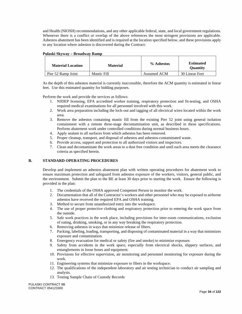
PULASKI CONTRACT 8B CONTRACT 054123300
Page 34 of 122
and Health (NIOSH) recommendations, and any other applicable federal, state, and local government regulations. Whenever there is a conflict or overlap of the above references the most stringent provisions are applicable. Asbestos abatement has been identified and is required at the location specified below, and these provisions apply to any location where asbestos is discovered during the Contract: Pulaski Skyway – Broadway Ramp
Material Location Material % Asbestos Estimated Quantity
Pier 52 Ramp Joint Mastic Fill Assumed ACM 30 Linear Feet As the depth of this asbestos material is currently inaccessible, therefore the ACM quantity is estimated in linear feet. Use this estimated quantity for bidding purposes.
Perform the work and provide the services as follows:
1. NJDEP licensing, EPA accredited worker training, respiratory protection and fit-testing, and OSHA required medical examinations for all personnel involved with this work.
2. Work area preparation including the lock-out and tagging of all electrical wires located within the work area.
3. Remove the asbestos containing mastic fill from the existing Pier 52 joint using general isolation containment with a remote three-stage decontamination unit, as described in these specifications. Perform abatement work under controlled conditions during normal business hours.
4. Apply sealant to all surfaces from which asbestos has been removed. 5. Proper cleanup, transport, and disposal of asbestos and asbestos-contaminated waste. 6. Provide access, support and protection to all authorized visitors and inspectors. 7. Clean and decontaminate the work areas to a dust free condition and until each area meets the clearance
criteria as specified herein. B. STANDARD OPERATING PROCEDURES
Develop and implement an asbestos abatement plan with written operating procedures for abatement work to ensure maximum protection and safeguard from asbestos exposure of the workers, visitors, general public, and the environment. Submit the plan to the RE at least 30 days prior to starting the work. Ensure the following is provided in the plan:
1. The credentials of the OSHA approved Competent Person to monitor the work. 2. Documentation that all of the Contractor’s workers and other personnel who may be exposed to airborne
asbestos have received the required EPA and OSHA training. 3. Method to secure from unauthorized entry into the workspace. 4. The use of proper protective clothing and respiratory protection prior to entering the work space from
the outside. 5. Safe work practices in the work place, including provisions for inter-room communications, exclusion
of eating, drinking, smoking, or in any way breaking the respiratory protection. 6. Removing asbestos in ways that minimize release of fibers. 7. Packing, labeling, loading, transporting, and disposing of contaminated material in a way that minimizes
exposure and contamination. 8. Emergency evacuation for medical or safety (fire and smoke) to minimize exposure. 9. Safety from accidents in the work space, especially from electrical shocks, slippery surfaces, and
entanglements in loose hoses and equipment. 10. Provisions for effective supervision, air monitoring and personnel monitoring for exposure during the
work. 11. Engineering systems that minimize exposure to fibers in the workspace. 12. The qualifications of the independent laboratory and air testing technician to conduct air sampling and
analysis. 13. Testing Sample Chain of Custody Records
PULASKI CONTRACT 8B CONTRACT 054123300
Page 35 of 122
14. Required Permits, Clearances, and Licenses. C. NOTIFICATIONS, PERMITS, WARNING SIGNS, LABELS, AND POSTERS. Comply with the following:
1. Erect warning signs around the workspace and at every point of potential entry from the outside, with the words "Danger, Asbestos Hazard, Do Not Enter". Provide warning signs in an easily noticeable, bright color. At a minimum, meet OSHA requirements for the size of the sign and the size of the lettering. Post warning signs at the entrance to the work area and around its perimeter at intervals of no more than twenty-five (25) feet.
2. Provide the OSHA required labels for all plastic bags and all drums utilized to transport contaminated material to the landfill.
3. Provide any other signs, labels, warnings, and posted instructions that are necessary to protect, inform and warn people of the hazard from asbestos exposure. Post in a prominent and convenient place for the workers the latest copy of any applicable regulations from OSHA, EPA, NIOSH, and State of New Jersey.
4. Pay all license fees and royalties and assume all costs incident to the use in the performance of the work or the incorporation in the work of any invention, design, process, product or device which is the subject of patent rights or copyrights held by others including patent rights or copyrights held by the Department or the NJDEP. If a particular invention, design, process, products, or device is specified in the Contract for use in the performance of the work, and its use is subject to any license fee or other copyrights calling for the payment of any license fee or royalty to others, disclose the existence of such rights. Assume sole responsibility for all damages, losses, and expenses arising out of any infringement of patent rights or the work or resulting from the incorporation in the work of any invention, design, process, product or device not specified in the Contract, and defend all such claims in connection with any alleged infringement of such rights and hold the Department and the NJDEP harmless from any damages, losses and expenses including counsel fees.
D. NOTIFICATION OF POLICE. Notify local police of the asbestos abatement work in writing prior to the start
of work E. EMERGENCY PRECAUTIONS. Comply with the following:
1. Establish emergency and safety protocol procedures to be implemented in the event of fire or medical emergency. Provide two (2) extra full sets of protective clothing and respirators available at all times.
2. Notify local medical emergency personnel, ambulance crews and hospital emergency room staff, prior to commencement of abatement operations as to the possibility of having to handle contaminated or injured workmen. Advise local medical emergency personnel on safe decontamination procedures.
3. Be prepared to administer first aid to injured personnel after decontamination. Treat seriously injured personnel immediately or evacuate without delay for decontamination. If an injury occurs, take steps to reduce airborne fiber concentrations (i.e. misting of the air with water) until the injured person has been removed from the work area.
4. Notify the local police to the danger of entering the work area before the start of actual removal of the asbestos material.
F. SUBMITTALS DURING THE WORK. Submit copies of the following items to the RE:
1. Security and safety logs showing names of person entering workspace, date and time of entry and exit, record of any accident, emergency evacuation, and any other safety and/or health incident.
2. Daily progress logs showing the number of workers, supervisors, hours of work and tasks completed. 3. Current work progress. 4. Chain of Custody Records. 5. Disposal Certificates. 6. All Air Monitoring and Inspection Results.
G. RESPONSIBILITIES. Comply with the following: 1. Remove all items that are not permanently fixed from the area that may impede the work.
PULASKI CONTRACT 8B CONTRACT 054123300
Page 36 of 122
2. Coordination with the RE to ensure the Department will not occupy the area in which work is being performed during the entire asbestos removal operation, including completion of clean-up.
3. During this period, be responsible for all areas affected by the operation including on a 24-hour basis, providing a means of securing the work area to prevent theft, vandalism and unauthorized entry.
4. Should the failure of any utility occur, the Department will not be responsible for loss of time or any other expense.
H. USE OF FACILITIES. Comply with the following:
1. Provide all required amounts of water and electric power as required for the asbestos abatement work. 2. Provide all electrical, water, and waste connections, tie-ins, extensions, and construction materials,
supplies, etc. 3. Provide fire protection in accordance with all State and local codes.
I. USE OF THE PREMISES. Comply with the following: 1. Confine apparatus, the storage of materials, and supplies, and the operation of workmen to limits
established by law, ordinances, and the directions of the RE. In an attempt to obviate fire, store all flammable or combustible materials in areas approved by the RE.
2. Assure that no exits from the work area are obstructed, establish appropriate safety barriers to prevent access, and keep work areas neat, clean, and safe.
3. Provide a steel enclosed dumpster with steel lockable top or doors. Locate the dumpster on the premises and clearly mark the dumpster as containing asbestos waste. Remove the dumpster from the site immediately after being filled to the intended capacity and transport it directly to the designated landfill for disposal.
4. Comply explicitly with all policies, procedures, directives and instruction issued by the owner regarding safety and security.
J. PROTECTION AND DAMAGE. Comply with the following: 1. Replace or repair any items damaged, due to work performed under this Contract, equal to their original
construction and finish. Repaired or replaced items will be subject to the RE’s approval. 2. Do not throw any asbestos materials into any onsite containers but those provided and approved for that
use. 3. Remove debris from the site daily. Leave premises neat and clean after each work shift so that work may
proceed the next regular workday without interruption.
K. RESPIRATORY PROTECTION SYSTEMS. Comply with the following: 1. Provide all workers, foremen, superintendents, authorized visitors and inspectors personally issued and
marked respiratory equipment approved by NIOSH and OSHA. When respirators with disposable filters are employed, provide sufficient filters for replacement as necessary by the worker.
2. With no exceptions, require that each person entering the Work Area wear an approved respirator and protective clothing.
3. Provide respiratory protection in accordance with OSHA Regulations, 29 CFR 1910.1001 (Asbestos Standard for General Industry), 1926.58 (Asbestos Standards for Construction), and 1910.134 (Respirator Standard), and ANSI Z88.2-1980. Respirators (d). Provide respirators also approved by NIOSH under the provisions of 30 CFR Part 11.
4. At a minimum, meet the following respiratory protection requirements: 0.010 - 0.1 f/cc Dual cartridge negative pressure air purifying respirator with HEPA cartridge 0.1 - 5.0 f/cc Powered air purifying respirator with HEPA cartridge 5.0 - 10.0 f/cc Full face Type C supplied air operated in pressure demand mode with HEPA
filter disconnect >10.0 f/cc Full facepiece Type C supplied air operated in pressure demand mode with
auxiliary positive pressure self-contained breathing apparatus (5 minute bottle) 5. Permit no one into the work area at any time, during any phase of the work. without proper protection
including suits and respirators. 6. Ensure disposable dust masks are not used at any time of the operations. 7. Ensure all personnel engaged in asbestos removal procedures requiring a respirator have an unobstructed
face/mask seal (i.e., no facial hair).
PULASKI CONTRACT 8B CONTRACT 054123300
Page 37 of 122
L. PROTECTIVE CLOTHING. Comply with the following:
1. Provide to all workers, foremen, superintendents and authorized visitors and inspectors protective disposable clothing consisting of full-body coveralls, head covers, gloves and one-half meter high boot type covers or reusable footwear.
2. Provide eye protection and hard hats as required by job conditions and safety regulations. 3. Leave reusable footwear, hard hats and eye protection devices in the designated work area until the end
of the asbestos abatement work. 4. Discard and dispose of disposable protective clothing as asbestos waste every time the wearer exits from
the work area and proceed directly to the decontamination facility. M. AIR MONITORING. Comply with the following:
1. Employ an independent laboratory and an air testing technician to conduct air sampling and analysis in accordance with OSHA Regulation 1926.58 (Asbestos Standards for Construction), and 1910.134 (Respirator Standard).
2. Require the Testing Laboratory to be a current proficient participant in the NIOSH PAT Program and accredited by the American Industrial Hygiene Association (AIHA), or under the direction of an ABIH Certified Industrial Hygienist. Submit for approval the laboratory identification number to the Environmental Consultant.
3. Require the Testing Laboratory to also be a current proficient participant in the NIST/NVLAP Quality Assurance Program for the identification of bulk samples. Submit Testing Laboratory identification number for approval to the RE.
4. Require an OSHA approved Competent Person from the testing laboratory to perform the following functions:
a. Monitor the setup of the work area enclosure and ensure its integrity. b. Control entry and exit into the work enclosure. c. Ensure that employees are adequately trained in the use of engineering controls, proper work
practices, proper personal protective equipment and in decontamination procedures. d. Ensure that employees use proper engineering controls, proper work practices, proper personal
protective equipment and proper decontamination procedures. e. Check for rips and tears in work suits, and ensure that they are mended immediately or replaced. f. Supervise all employee exposure monitoring in compliance with OSHA Regulation 1926.58
Appendix "A". g. Conduct air sampling as per OSHA 1926.58 and as described herein.
5. Require such individual, designated as the Competent Person to meet all criteria defining a competent person as defined in OSHA Regulation 1926.32 (f). Require such individual to be:
a. A certified industrial hygienist or an air testing hygienist with a minimum of six (6) months experience in the monitoring of asbestos abatement projects or
b. An industrial hygiene or environmental technician with a minimum of six (6) months experience in the monitoring of asbestos abatement projects and successful completion of a course in air monitoring from an approved institution.
6. Require that the Competent Person supervise the air monitoring and inspection. 8. Instruct or certify the air testing technician on the dangers of asbestos, respirator use, proper fit and
testing of approved respirators, and proper decontamination through a training program endorsed or conducted by the USEPA. Ensure the technician receives a medical examination and fit testing in accordance with OSHA Regulation 1926.58.
9. Continuous monitoring and inspection will include work area samples, personnel samples from the breathing zone of a worker to accurately determine the employees' 8-hour TWA and decontamination unit clean room samples.
10. Require the air testing technician to take work area samples and employee personnel samples using pumps whose flow rates can be determined to an accuracy of +5% at a rate of 2 liters per minute. The air testing technician must demonstrate this at the job site.
11. Provide sampling and analysis methods in accordance with NIOSH 7400A. 12. Provide verbal air sample results to the RE within 24 hours, and deliver and post written results at the
job site within 48 hours. These may be hand-written.
PULASKI CONTRACT 8B CONTRACT 054123300
Page 38 of 122
13. Require the air testing technician to conduct air monitoring on a daily basis per OSHA Regulation 1926.58 and include full shift personal time weighted average monitoring (unless Type C respirators are utilized) and include but not necessarily be limited to:
a. Inside Work Area Min. Volume per sample Stationary (Area) sufficient to achieve a Samples (2) detection limit of 0.1 f/cc
b. Clean Room of 900 liters minimum Decontamination Unit (2) Commence daily monitoring from the time the regulated area is established and continue until satisfactory final air samples are achieved.
14. Require a Competent person to conduct inspections and provide written reports daily. Inspections will include checking the standard operating procedures, engineering control systems, respiratory protection and decontamination systems, packaging and disposal of asbestos waste, and any other aspects of the work that may affect the health and safety of the people and environment.
15. Incur all costs for required air monitoring by the competent person. 16. As soon as air monitoring tests are completed, require the Testing Laboratory to send the results of such
tests to the RE and any designated Department representative. 17. The Department reserves the right to conduct air and surface dust sampling in conjunction with and
separate from the Testing Laboratory for the purposes of Quality Assurance.
N. AIR MONITORING – DEPARTMENT. The Department will also monitor the work with an Asbestos Safety Control Monitoring Firm (ASCM). Comply with the following in support of that monitoring:
1. An Asbestos Sampling Technician from the ASCM will provide continuous monitoring and inspection to include work area inspections and air samples outside of the work area to ensure that these areas remain free from contamination. Acceptable levels outside the work area will be:
0.010 fibers/cc - Analysis via Phase Contract Microscopy or 0.010 structures/cc - via Transmission Electron Microscopy
2. Inspections will include checking the standard operating procedures, engineering control systems, respiratory protection and decontamination systems, packaging and disposal of asbestos waste, and any other aspects of the work that may affect the health and safety of the people and environment.
3. Provide the Asbestos Sampling Technician access to all areas of the asbestos removal work at all times for continuous inspection and performance monitoring to verify that said performance complies with this specification and the requirements of all applicable state and federal regulations. Ensure the Asbestos Sampling Technician is on site throughout the entire abatement operation.
4. The Asbestos Sampling Technician has the authority to test the seal of the respirator of all who enter the work site to ensure a proper fit. In matters of gross negligence and/or flagrant disregard for the safety of others, including the possibility of contaminating the environment and the appearance of an emergent, unsafe condition at the work site, the Asbestos Sampling Technician has the authority to stop work. In the event of continual noncompliance or serious violation, the Asbestos Sampling Technician will coordinate with the RE to issue a written Stop Work Order and secure the work site until all violations are abated.
5. The Asbestos Sampling Technician, upon receipt of testing results indicating that concentrations above 0.010 fibers/cc have occurred outside the work area or above 0.020 fibers/cc within the clean room of the decontamination chamber during the abatement action will report these results to the RE within one working day verbally or by telephone so that prompt corrective action may be taken.
6. The Asbestos Sampling Technician will maintain a daily log of on-site observations concerning compliance with activities required under this specification. The Asbestos Sampling Technician will at all times make this log available upon request to the Department and to appropriate local and State agencies.
7. The Asbestos Sampling Technician will monitor the removal phase as follows: a. Provide monitoring outside of the work area throughout removal operations, to ensure that no
outside contamination is occurring. b. Assemble filter cassettes and sampling train as specified in NIOSH #7400A. Verify the flow
rate is between 1 and 15 liters per minute. Verify the total volume is sufficient to achieve a detection limit of 0.010 f/cc.
c. Provide a minimum of three (3) samples per day. One stationary sample at decontamination unit entrance/exit and two samples adjacent to work area but remote from the decontamination
PULASKI CONTRACT 8B CONTRACT 054123300
Page 39 of 122
unit entrance. In the selection of adjacent areas to be monitored, preference is for the sampling areas adjacent to the active work area.
d. Advise the RE if they observe a malfunction in the control methods if problems are not corrected immediately.
e. Use NIOSH Method #7400A to analyze air samples. f. Verify the maximum turn-around time for analysis of the samples is 24 hours from the
completion of each work shift. g. Verify the evaluation criteria is 0.010 fibers per cubic centimeter via PCM. h. Keep a record in a daily log of all on-site observations, and required activities.
8. Submit a final report by the ASCM as follows: a. Upon satisfactory completion of all asbestos removal work and of all tests, submit a
comprehensive written final report to the Department, including copies of all back-up records (charts, logs, calibration results, records, etc.) documenting the day-by-day progress of work and related tests, deficiencies and air sampling results. Present this report in a logical form, neatly bound, and properly titled, dated and signed.
b. Highlight in the report any deviations from acceptable practice and any unsatisfactory test results reported by the Asbestos Sampling Technician during the course of the job
c. Submit least three copies of this report to the Department and RE within 30 days after the completion of the work.
O. TAMPERING WITH TEST EQUIPMENT
Any tampering with testing equipment will be considered an attempt at falsifying reports and records to federal and state agencies and each offense will be prosecuted under applicable state and federal criminal codes to the fullest extent possible.
P. MATERIALS HANDLING
Deliver all materials to the job site in their manufacturer's original container, with the manufacturer's label intact and legible.
1. Maintain package materials with seals unbroken and labels intact until time of use. 2. Store all materials on pallets, away from any damp and/or wet surface. Cover materials in order to
prevent damage and/or contamination. 3. Promptly remove damaged materials and unsuitable items from the job site, and promptly replace with
material meeting the specified requirements, at no additional cost to the Department.
The Department may reject as non-complying such material and products that do not bear identification satisfactory as to manufacturer, grade, quality and other pertinent information.
Q. MATERIALS. Comply with the following:
1. Wetting Agents: BWE 5000 as manufactured by Better Working Environments Inc. of San Diego, California or approved equal.
2. Sealants: Penetrating and bridging and may be applied by a one or two coat system, meeting the following criteria:
a. ASTM Standard E84-84 b. Underwriter's Laboratory Approval for Class 1A c. Fire Rating: Class A
(1) Flame Spread: 0-25 (2) Fuel Contribution: 10 (3) Smoke Density: 5
3. Framing Materials and Doors: As required to construct temporary decontamination facilities and critical barriers. Provide high grade, new, kiln dried, finished one side and fire retardant lumber.
4. Fire Retardant Clear Polyethylene Sheeting: Provide largest size possible to minimize seams minimum thickness 6 mil.
5. Fire Retardant Black Plastic Sheeting: Provide largest size possible to minimize seams minimum thickness 6 mil to obscure view of work areas from public view.
PULASKI CONTRACT 8B CONTRACT 054123300
Page 40 of 122
6. Drums: Asbestos transporting drums, sealable and clearly marked with warning labels as required by OSHA and EPA.
7. Plastic Bags: Sealable, asbestos disposal bags, minimum 6 mil thick, clearly marked with warning labels as required by OSHA and EPA.
8. Signs: Asbestos warning signs for posting at perimeter of work area, as required by OSHA and EPA. 9. Waste Container Bag Liners and Flexible Trailer Trays: One piece leak-resistant flexible tray with
absorbent pad, as manufactured by Packaging Research and Design Corporation, Madison, Wisconsin 39130, or approved equal.
10. Tape: Provide tape which is of high quality with an adhesive which is formulated to aggressively stick to sheet polyethylene, as manufactured by Nashua Tape Products, Waterviolet, New York, or approved equal.
11. Spray Adhesive: Provide spray adhesive in aerosol cans, which are specifically formulated to stick tenaciously to sheet polyethylene, as manufactured by 3M, Nashua, or approved equal.
12. Flexible Duct: Spiral-reinforced flex duct for air filtration devices. 13. Disposable Coveralls: Dupont "Blockade" as manufactured by Dupont Company of Wilmington,
Delaware; "Kleenguard Limited Use Coveralls" or "Duraguard" Coveralls as manufactured by Kimberly-Clark Corporation of Rosewell, Georgia, or approved equal.
R. TOOLS AND EQUIPMENT. Comply with the following:
1. Transportation Equipment: Suitable for loading, temporary storage, transit and unloading of contaminated waste without exposure to persons or property. Ensure any temporary storage containers are metal closed dumpsters capable of being locked.
2. Vacuum Equipment: Utilize HEPA filtration systems for all vacuum equipment in the work area. Provide GS81 or GS83 vacuum equipment as manufactured by NilFisk of America, Malvern, New Jersey or Norclean Vacuum Systems distributed by Power Products and Services Corporation, Inc., or approved equal.
3. Vacuum Attachments: Soft Brush Attachment, Asbestos Scraper tool, Drill Dust Control kit. 4. Electric Sprayer: An electric airless sprayer suitable for application of encapsulating materials and
approved by and listed with Underwriters Laboratory. 5. Water Sprayer: Airless or other low pressure sprayer for amended water application. 6. Hand Power Tools: Equipped with HEPA-filtered local exhaust ventilation if used to drill, cut into or
otherwise disturb ACM. 7. Other Tools and Equipment: Provide other suitable tools for the stripping, removal, encapsulation, and
disposal activities including but not limited to: hand-held scrapers, sponges, rounded edge shovels, brooms and carts.
8. Water Hoses: Employ heavy-duty, abrasion-resistant hoses with a pressure rating greater than the maximum pressure of the water distribution system to provide water to each work area and to each decontamination unit. Provide fittings as required to allow for connection to existing hydrants or spouts, as well as temporary water heating equipment, branch piping, showers, shut-off nozzles and equipment. Include back flow prevention for all connections to water systems.
9. Electrical Service: a. General: Comply with applicable NEMA, NECA and UL standards and governing regulations
for materials and layout of temporary electric service. b. Temporary Power: Provide service to decontamination unit subpanel with minimum 60 AMP,
2 pole circuit breaker or fused disconnect connected to the onsite generator. Size and equip the subpanel and disconnect to accommodate all electrical equipment required for completion of the work.
c. Voltage Differences: Provide identification warning signs at power outlets, which are other than 110-120 volt power. Provide polarized outlets for plug-in type outlets, to prevent insertion of 110-120 volt plugs into higher voltage outlets. Provide dry type transformers where required to provide voltages necessary for work operations.
d. Ground Fault Protection: Equip all circuits for any purpose entering work area with ground fault circuit interrupters (GFCI). Locate GFCI's exterior to work area to protect all circuits prior to entry to work area. Provide circuit breaker type ground fault circuit interrupters (GFCI) equipped with test button and reset switch for all circuits to be used for any purpose in work
PULASKI CONTRACT 8B CONTRACT 054123300
Page 41 of 122
area, contamination units, exterior, or as otherwise required by NEC, OSHA or other authority. Locate in panel exterior to work area.
e. Power Distribution System: Provide circuits of adequate size and proper characteristics for each use. In general, run wiring where wiring will be least subject to damage from operations.
f. Electrical Power Cords: Use only grounded extensions cords; use hard service cords where exposed to traffic and abrasion. Use single lengths of cords only.
g. Temporary Lighting: If needed, provide work area lighting that is liquid, moisture proof, and designed for the use intended. (1) Provide sufficient temporary lighting to ensure proper workmanship everywhere; by
combined use of daylight, general lighting, and portable plug-in task lighting. (2) Provide lighting in the Decontamination Unit as required supplying a minimum 150
foot candle light level. S. DECONTAMINATION FACILITY. Comply with the following:
1. Ensure the attending Asbestos Sampling Technician designates the location for a portable worker decontamination facility that will consist of a changing room, equipment room and a shower room.
2. Construct a decontamination facility consisting of three separate 4’x 4’rooms with a 2” x 4” x 8 foot high wooden frame and with two layers of 6 millimeter plastic sheeting on floors, walls and ceiling.
3. Install airlocks at the entrance to each individual room and attach the unit directly to the containment consisting of three (3) weighted layers of 6 millimeter polyethylene sheeting. Attach these layers on alternate sides of opening and paint arrows on each sheet to direct persons in the proper direction for entry or exit.
4. Supply the shower unit with both hot and cold water, towels and soap. 5. Provide temporary connections for piping, hoses, etc., as required for hot and cold water. 6. Add waste shower water to asbestos contaminated waste before disposal in an approved landfill. 7. Provide all temporary electrical fixtures as required for temporary lighting, heating, etc., of the work and
shower area. 8. Ensure workers proceed from the removal area directly to the decontamination unit.
T. DECONTAMINATION SEQUENCE. Comply with the following:
1. Ensure all workers and other persons who enter the work area remove street clothes, put on two clean overalls, and a respirator prior to entering the abatement work area.
2. Ensure workers remove all gross contamination and debris from the coveralls before leaving the work area. As required, allow workers to assist each other in brushing each other off or vacuuming with HEPA filter equipment vacuums approved for asbestos cleanup.
3. The worker then takes off the outer coverall and proceeds to the shower unit. The worker removes the second coverall and respirator in the shower area. The worker may place contaminated extra clothing in a bag for disposal with other ACM material.
4. Ensure workers remove respiratory protection equipment after completely showering to prevent inhalation of fibers.
5. After showering, the worker moves to a clean area and dresses in either new coveralls for another entry or street clothes if leaving.
6. Do not allow workers to eat, drink, smoke, chew gum or tobacco in the work area. IF any of the above are done, ensure the workers follow the complete decontamination sequence.
7. Ensure work footwear remains inside the work area until completion of the work. Ensure workers dispose of or clean footwear by washing in the shower at the end of the work.
8. Assign a worker to collect contaminated respirators, clean them, and re-filter them after each use. 9. Ensure everyone entering the work area follows this procedure completely every time he/she enters and
leaves the work area. 10. In order to prevent contamination of the environment, control access at the work site and maintain a
daily log of personnel entering the work area. Post a list of names of workers with their start and stop times for each day.
U. METHOD OF ASBESTOS REMOVAL. Comply with the following:
PULASKI CONTRACT 8B CONTRACT 054123300
Page 42 of 122
1. After isolation, protection and authorization to proceed, proceed with the work in the following sequence:
a. Spray asbestos material with water containing a wetting agent to enhance penetration (amended water). Apply a fine, low-pressure spray of this solution to prevent fiber disturbance preceding removal. Saturate the material sufficiently to prevent emission of airborne fibers in excess of the exposure limits prescribed in the OSHA regulations without causing excess dripping. Spray wetted or amended water on as many times and as often as necessary to ensure that the asbestos material is adequately wetted throughout (especially that asbestos nearest the substrate) to prevent dust emission as specified in the OSHA regulations.
b. Remove the asbestos material in small sections in two person teams. c. Immediately pack and seal removed wet material into containers as specified.
2. After completion of this removal phase (stripping), clean all surfaces from which asbestos has been removed to remove all visible asbestos-containing material. Keep surfaces being cleaned wet using amended water during this work. Package all disposable equipment for disposal. Wash containers with amended water and have all exterior particulate matter removed prior to removal from the contaminated area.
3. Request the Asbestos Sampling Technician perform a pre-sealant inspection after all asbestos containing material has been removed and prior to the application of any sealant material. Notify the Asbestos Sampling Technician, one (1) hour prior to the time the work will be ready for inspection.
4. When all asbestos removal is completed, spray or paint the locations from which asbestos has been removed with one coat of sealant.
5. Commence final cleanup of work area. V. PROGRESS INSPECTIONS. Comply with the following:
1. Ensure that the asbestos abatement work progresses in accordance with the governing laws. Ensure the Asbestos Sampling Technician is continuously present to observe the progress of work and perform inspections and tests.
2. If the Asbestos Sampling Technician observes irregularities at any time, complete any necessary corrective action as recommended by the Asbestos Sampling Technician. If corrective action is not taken, or if workers habitually and/or excessively violate the requirements of any regulation, the Asbestos Sampling Technician is authorized to order the work stopped in writing and advise the RE. Upon failure to comply with the order, any non-conforming or unacceptable work that may have to be repaired or replaced will be done at no cost to the Department.
3. Where a sealant is required to be applied after removal, the Asbestos Sampling Technician will conduct a pre-sealant inspection to ensure that all asbestos containing material has been removed properly before the sealant is applied. Notify the Asbestos Sampling Technician, one (1) hour prior to the time the work will be ready for inspection. Prior to applying the sealant, obtain in writing from the Asbestos Sampling Technician if the pre-sealant inspection is acceptable.
W. EMERGENCY CLEAN-UP OF CONTAMINATED AREAS
1. Utilize the following procedures during any situation the Asbestos Sampling Technician considers to be of an emergency nature:
a. The ASCM testing laboratory has notified the Department a discovery of outside contamination. The Asbestos Sampling Technician will extend the range of testing to verify if asbestos fibers have infiltrated beyond the work area.
b. Respond immediately to the directions of the Asbestos Sampling Technician. c. Require all personnel entering the affected area to wear full body and respirator protection as
described in these specifications. d. Seal off the area and post warning signs along the perimeter of the area. e. Clean the entire area via HEPA vacuum and wet wiping techniques starting from the uppermost
area(s) and working down to ground level. Thoroughly clean and decontaminate ALL items in the affected area to the satisfaction of the Asbestos Sampling Technician.
2. The ASCM testing laboratory will provide air monitoring before, during and after clean-up operations are completed. Testing laboratory will perform air sampling to ensure that all asbestos fibers have been removed from the area and to verify airborne concentrations do not exceed 0.010 f/cc of air when
PULASKI CONTRACT 8B CONTRACT 054123300
Page 43 of 122
analyzed via PCM. Should analysis show concentrations exceed the level of 0.010 f/cc, clean the entire affected area until it meets with the standards listed herein.
X. DECONTAMINATION OF WORK AREA (ALL PHASES)
1. The following procedures must be accomplished utilizing protective clothing: a. Clean all surfaces in the work area, applying a fine spray or mist of amended water to all
surfaces, following with the wet wiping procedure using disposable cloths. Dispose or thoroughly rinse these cloths on a frequency sufficient to eliminate visible accumulation of debris.
b. Notify the Asbestos Sampling Technician in writing that a pre-sealant inspection is requested. c. After completion of cleaning all surfaces in the work area and upon receiving a satisfactory pre-
sealant inspection, spray coat all dried exposed surfaces with a sealant. Ensure the color of this coat is separate and distinct from the underlying substrate. Include surfaces from which asbestos containing materials have been removed, non-removable fixtures, and equipment in the surfaces to be coated. Apply the sealant by an electric airless spray gun. Consult manufacturer's specifications for pressure ratings.
d. Dispose of rags, mops and any other disposable cleaning materials and utensils in sealed plastic bags with asbestos contaminated waste labels.
e. Wet clean with amended water all walls, floors and other surfaces. Allow all surfaces to dry. 2. Notify the Asbestos Sampling Technician that a cleanup inspection can be performed to ensure all visible
asbestos has been removed and the area is asbestos free. 3. Conduct cleanup inspections as follows:
a. Request a notice for clean-up inspection at least one (1) hour in advance on the desired date of inspection;
b. Ensure the Asbestos Sampling Technician conducts the clean-up inspection prior to the removal of work area barriers;
c. Obtain verification from the Asbestos Sampling Technician that: (1) The work site is properly cleaned and is free of visible asbestos and
asbestos-containing material; (2) All asbestos is properly packaged and removed from the work area to an enclosed,
lockable dumpster. 4. After completion of the cleaning operations:
a. Perform a complete visual inspection of the work area to ensure that it is dust free. b. Request a visual inspection of the work area to determine if the scope of work has been satisfied. c. If the above criteria have not been met, re-clean all surfaces using wet cleaning. Repeat this
process of recleaning, allowing surfaces to dry and re-testing until compliance is achieved. 5. Once all visual inspections have passed and the work area is clean and dry, request the Asbestos
Sampling Technician conduct clearance air sampling in accordance with State and federal requirements. If the clearance results are unacceptable, repeat additional cleanup and testing until compliance is achieved.
6. If all is in order, request the Asbestos Sampling Technician issue a written notice of authorization to remove barriers from the job site. If the final visual inspection results are unacceptable, clean as needed to achieve compliance.
7. The following steps may be performed without utilizing protective clothing; respiratory protection required after the work area is found to be in compliance:
a. Remove all barriers. b. Dispose of plastic sheeting, tape, and other debris in sealable plastic bags labeled as
contaminated waste. c. Dispose of cloths or sponges used in the cleaning operation as contaminated waste.
8. If air quality monitoring results are not in compliance, repeat all steps until compliance is obtained. Y. REMOVAL AND STORAGE OF REGULATED MATERIAL. Comply with 202.03.05 and the following:
1. Obtain Asbestos Sampling Technician direction on all routes to be used for the transportation of contaminated wastes to the storage area.
PULASKI CONTRACT 8B CONTRACT 054123300
Page 44 of 122
2. Coordinate a time of disposal of all contaminated waste with the RE. Ensure that random removal of contaminated waste from the work site does not occur.
3. Do not throw any materials from the work area. 4. Remove debris from the site daily. Leave premises neat and clean after each work shift, so that work
may proceed the next regular workday without interruption. 5. Federal Regulations, 40 CFR 61.150 (a)(1)(iii) which prescribes a leak-tight container, including
maintaining the integrity of the container until after deposition at a sanitary landfill which is run in accordance with 40 CFR 61.154. Therefore, caution must be used in the choice of container types and consideration given to the method of unloading at the landfill. Package and seal in leak-proof containers all asbestos or asbestos-contaminated materials.
a. Double bag all waste material utilizing 6 mil. polyethylene bags. Do not overfill bags. Evacuate all air from bags with a HEPA filter equipped vacuum. Seal the top of the bags by twisting the open end and then tying an overhand knot in the twisted material. Do not seal bags with cord or wire.
b. Cut contaminated material containing sharp-edged items to size while adequately wet, place in plastic bag lined boxes. Seal bag or close and seal box. Place box in a labeled plastic bag or tightly wrap and seal box in plastic sheeting.
c. Large sized contaminated material may be wrapped in two (2) layers of 6 mil. polyethylene sheeting and secure with duct tape. Ensure the wrapped material is sealed air and watertight. Apply OSHA required warning labels to outside of plastic sheeting.
d. Obtain disposal drums, where applicable, constructed out of metal or plastic-lined fiberboard with locking ring tops.
e. Obtain bags and drums marked with a pre-printed label as prescribed by 40 CFR Section 61.150 (a)(1)(v) of the EPA regulations; by section 29 CFR 1926.58(k)(2) or 1910.1001 (J)(2) of the OSHA regulations and by 49 CFR Parts 171 and 172 of the Department of Transportation regulations.
6. Store all asbestos-containing or asbestos-contaminated materials in a securely locked dumpster or storage area. Obtain approval from the Asbestos Sampling Technician prior to the use of any dumpster or storage area. Affix required warning labels to the outside of the dumpster or storage area.
a. Ensure the container used for the storage of bagged contaminated waste is an enclosed dumpster with a solid metal roof and solid metal door with padlock. Do not store unbarred contaminated waste or non-asbestos waste in these dumpsters. Ensure that all bags and drums placed in dumpster are undamaged. Post warning signs on the dumpster in accordance with Section 29 CFR 1926.58 (k)(1) of the OSHA regulations.
b. Provide a secured storage area for the storage of drummed contaminated waste prior to transport to the waste disposal site. Equip the storage area with lockable doors. Store only asbestos waste enclosed in drums or in dumpsters in the secure area. Ensure that drums stored in this area are undamaged. Post warning signs outside, on the perimeter of the secured storage area in accordance with Section 29 CFR 1926.58(k)(1) of the OSHA regulations.
Z. TRANSPORTATION OF REGULATED MATERIAL. Comply with 202.03.09 and the following:
1. Prepare all asbestos materials for transportation in accordance with the specifications and all applicable Federal, State, County and City Regulations. Submit the following documentation:
a. Applicable State haulers license and registration numbers. b. Federal Hazardous Materials haulers number. c. Designated landfill EPA Permit numbers.
2. Prepare enclosed cargo areas (dumpster) prior to loading asbestos waste as follows: a. Clean via HEPA vacuum and wet wipe techniques the enclosed cargo areas of all visible debris
prior to preparing with plastic. b. Line the cargo area with two (2) layers of 6 mil. Polyethylene sheeting to prevent contamination
from damaged or leaking containers. Install sheeting first that extends around the cargo area 24" minimum. Overlap and tape sheeting securely into place.
3. Place asbestos waste on level surfaces in the cargo area of the dumpster and pack waste tightly to prevent any shifting or tipping of the waste during transportation.
PULASKI CONTRACT 8B CONTRACT 054123300
Page 45 of 122
4. Do not throw or drop any asbestos containing waste from the dumpster. Handle all material carefully to prevent rupture of the containers.
5. Ensure all personnel engaged in handling and loading of contaminated waste outside of the work area wear protective clothing. Ensure disposable clothing includes head, body and foot protection and that the color of clothing is different from abatement personnel in the work area. Provide minimum respiratory protection of half face, dual cartridge, air purifying respirators with HEPA filters.
6. Immediately clean any debris or residue observed on containers or surfaces outside of the work area using HEPA equipped wet/dry vacuums only.
7. Transport all asbestos containing waste from the abatement site to the landfill using a registered waste hauler.
8. Ensure waste transport documents conform to the requirements of the U.S. Department of Transportation, Hazardous Materials Transportation Regulation, 49 CFR Part 173, and NESHAPS 40CFR 61.150 (d)(1) & (2). Clearly mark shipping documents with the required designation "R-Q-Asbestos". Provide a copy of this document to the Asbestos Sampling Technician.
9. Provide and sign a uniform hazardous waste manifest each time a dumpster load of asbestos-containing waste material is shipped. Ensure the uniform hazardous waste manifest includes the time, date, site of waste generation, the names and addresses of the Transporter, the Contractor, the landfill operator and information on the type and number of asbestos-waste containers. Provide the Asbestos Sampling Technician with signed copies of the waste manifest before each departure.
10. Transport asbestos-containing waste material from the abatement site directly to the specified disposal site. Do not accept material from any other site when transporting asbestos-containing waste material from the abatement site. Intermediate storage of waste material is not permitted.
AA. DISPOSAL OF ASBESTOS WASTE. Comply with 202.03.09 and the following:
1. This article describes the removal of asbestos from the job site and the disposal of asbestos waste. a. Conduct disposal of asbestos waste as follows:
(1) Wet and package all asbestos waste materials destined for disposal in permanently sealed, leaktight containers (such as 6 mil. plastic bags, double bagged with visible labels) in accordance with 40 CFR 61.150 - and 49 CFR Parts 171 and 172 before it can be legally transported and disposed. Do not permit the of haulage of loose asbestos.
(2) Ensure that asbestos waste, which is properly packaged, is classified as Waste ID #27, non-hazardous industrial waste, and disposed of at a landfill that is registered by the New Jersey Department of Environmental Protection (NJDEP) in conformance with the following: (a) Use a landfill registered by the US Department of Environmental Protection to accept
Waste ID #27; (b) The NJDEP must designate the specific landfill facility chosen as the recipient facility
for the community in which the removal work is located; (c) The waste hauler must possess a valid solid waste transporter registration issued by
the NJDEP. Ensure that the licensed solid waste transporter is a commercial collector/hauler or part of a registered Removal Company.
(d) Asbestos waste can be hauled in dumpster containers provided the load is comprised only of asbestos in bags and does not contain any other wastes or asbestos-containing wastes which could compromise the integrity of the permanent containers;
(e) If rough surfaces or other materials are present in the load, which could potentially puncture the permanent containers, then enclose those containers with temporary fiber or steel drums during loading, transport, and unloading operations. In addition, do not load or haul asbestos waste with vehicles containing compaction devices.
b. Provide a properly executed Chain of Custody record with each load of asbestos waste. Initiate the Chain of Custody and pass it to the transporter and disposal site operator. Ensure the transporter maintains a copy signed by the disposal site operator, and send additional copies to the RE and the NJDEP. Include the following in each Chain of Custody: (1) Name and address of generator; (2) Name and address of pickup site; (3) Estimated quantity of asbestos waste;
PULASKI CONTRACT 8B CONTRACT 054123300
Page 46 of 122
(4) Types of containers used; (5) Destination of waste.
201.03.09 Temporary Shielding THE FOLLOWING IS ADDED AFTER THE FIRST PARAGRAPH: Also conform to the following for work on the truss structure:
1. Shields horizontally under the full width of the truss and extends beyond the outer most face of the exterior truss member.
2. Extends vertically from the horizontal surface of the shielding up to the underside of the existing span truss floorbeams. Design the vertical shield to prevent any materials from exiting.
Ensure any storage on the work platforms and temporary shielding installed by Contractor is as allowed by the loading analysis submitted and certified with the Erection Plan as specified in 506.03.01.
201.04 MEASUREMENT AND PAYMENT THE FOLLOWING ITEM IS ADDED:
Item Pay Unit ASBESTOS REMOVAL, BRIDGE NO. ___ LUMP SUM
THE FOLLOWING IS ADDED:
The Department will not make payment for the Item CLEARING SITE in excess of $500,000 until Completion.
The Department will not make payment for the Item CLEARING SITE, BRIDGE (0901-150) in excess of $6,223,000 until Substantial Completion.
SECTION 202 – EXCAVATION
202.03.01 Stripping THE SECOND PARAGRAPH IS CHANGED TO:
Strip vegetation and underlying soil to a depth of 4 to 6 inches below the existing ground surface. Confirm the thickness of stripping with the RE based on field conditions. Temporarily store in stockpiles, as specified in 202.03.03.B, stripped material including excess that is determined suitable for the future use of the Department. The Department will sample and analyze stripped material in stockpiles to determine suitability for use as topsoil. Reuse or dispose of unsuitable stripped material as specified in 202.03.03.C.
202.03.02 Excavating Test Pits THE FOLLOWING IS ADDED AT THE END OF THE SECOND PARAGRAPH:
Provide temporary restoration of the test pit locations.
202.03.05 Excavating Regulated Material THE FOLLOWING IS ADDED AFTER THE SECOND PARAGRAPH: Contain onsite all ground water encountered during excavation activities, dewatering operations, and micropile installations and dispose onsite as specified in the Contract. THE FOLLOWING SUBPART IS ADDED: Section 202.03.12 Treatment, Operations, and Reporting of Ground Water Management
Properly treat all ground water and storm water within excavations encountered during excavation activities and dewatering operations within the Project Limits before being discharged to a surface water body in accordance with the issued Surface Water Discharge Permit (NJPDES BGR) and Treatment Works Approval (TWA) permit. Establish a
PULASKI CONTRACT 8B CONTRACT 054123300
Page 47 of 122
Pollution Prevention and Control Plan as specified in 202.03.04 prior to any excavation, dewatering, and ground water treatment for approval by the RE. Design a ground water treatment system in accordance with the TWA permit, including the “Construction Specifications for the Temporary Treatment System” Attachment No. 8, to meet the required NJPDES BGR effluent parameters. Provide a licensed water supply and wastewater treatment operator, who will be responsible for operation and maintenance (O&M) and sampling of ground water treatment system effluent, and the preparation of monthly discharge monitoring reports (DMR) to be submitted to the New Jersey Department of Environmental Protection (NJDEP) in accordance with the NJPDES for discharge to the surface water body shown on the Plans.
With the Pollution Prevention and Control Plan and at least 40 days prior to any excavation operations, submit a Ground Water Management Plan that includes the following, but not limited to:
1. Pumping and delivery systems of ground water to the treatment system. 2. Treatment system and any temporary storage facilities. 3. Qualifications of the licensed water supply and treatment operator. 4. Staging methods and locations to address the proposed sequence of construction operations. 5. Method and systems to discharge the treated water to the designated water body. 6. Maintenance of NJPDES BGR Outfall Signage.
Frac Tank(s) equivalent watertight vessel(s) may be used for temporary storage facilities if provided and maintained in compliance with the permits. When no longer needed for temporary storage, complete servicing, emptying/cleaning, and removal of the storage facilities. Empty the storage facilities of contaminated ground water and clean tank(s) of all contaminated sediments by a qualified cleaning company. Provide the RE with certification as clean for each tank prior to removal from the site. Dispose of sediments removed from the tanks at an approved disposal facility as specified in 202.03.09, except for materials from within the landfill. Ensure the Management Plan submitted includes the proposed number and location of tanks, how retained fluid will be pumped into the nearby treatment system before being discharged to a surface water body, and the cleaning company and disposal facility qualifications.
For ground water encountered during micropile operations, ensure slurry (grout/bentonite) does not enter the treatment unit by utilizing a belt and filter press system prior to transferring dewatered fluids to a temporary storage facility; or containerize onsite in frac tank(s), sample material, and the dispose of offsite at an approved disposal facility.
Within 20 days of the closure of the ground water treatment system, provide a letter of completion stating that all treatment works have been inspected and tested under the supervision of a Professional Engineer. Provide three copies of the letter to the RE, each signed and sealed by the Professional Engineer, referencing the Treatment Works Approval Permit number, name of the Permittee, and location of the treatment works. If more than one facility is implemented for the system, address that each facility was inspected and tested by a Professional Engineer.
202.04 MEASUREMENT AND PAYMENT THE FOLLOWING ITEM IS ADDED:
Item Pay Unit TREATMENT, OPERATIONS, AND REPORTING OF GROUND WATER MANAGEMENT LUMP SUM
SECTION 203 – EMBANKMENT 203.01 DESCRIPTION THE FOLLOWING IS ADDED:
This section also describes the requirements for installing geotextiles and other materials for roadway subgrade stabilization and landfill restoration. 203.02 MATERIALS 203.02.01 Materials THE FOLLOWING IS ADDED THE LIST OF MATERIALS:
Stabilization Geotextile ..................................................................................................................... 919.01
PULASKI CONTRACT 8B CONTRACT 054123300
Page 48 of 122
THE FOLLOWING IS ADDED:
The geotextile will have high resistance to degradation from ultraviolet, chemical and organic conditions that may possibly be encountered in the subgrade soil or overlying subbase or base course material. The mechanical and structural properties of the geotextile will equal or exceed the requirements of this specification.
THE FOLLOWING SUBPARTS ARE ADDED:
203.03.03 Roadway Stabilization
Ensure each shipment of geotextile conforms to the requirements of the approved materials questionnaire submittal and is furnished with a certification of compliance as specified in 106.07. A label clearly indicating the type and grade of material and the specification to which the material was manufactured is required for each roll. Check the geotextile upon delivery to ensure that the proper material has been received. During all periods of shipment and storage, protect the material from temperatures greater than 140 degrees F, or less than 32 degrees F, mud, dirt, dust and debris, or materials which may permanently affix to the geotextile. Follow the manufacturer’s instructions regarding protection from direct sunlight. The RE will reject the material if it has defects, tears, punctures, flaws, deterioration, damage incurred during manufacture, transportation or storage, or if the geotextile does not meet the requirements of this specification. Replace geotextile that is damaged during storage or installation. Install the geotextile in accordance with AASHTO M-288 Geotextile Specifications for Highway Applications and the following:
1. Grade and compact the subgrade to within a tolerance of plus or minus ½ inch of grade and contour, with no areas consistently high, as specified in 301.03.01.A prior to placing of any geotextile. Remove water pockets and sharp objects on the prepared surface that may tear or puncture the geotextile. Do not place geotextile on soft, muddy, or frozen surfaces. Excavate and replace unsuitable material with suitable material as specified in 301.03.01.B. Obtain RE approval before removing unsuitable material.
2. Fill in ruts, with additional material, that may be created in the subgrade due to construction traffic and compact it as specified in 301.03.01 prior to placement of geotextile. Obtain RE approval of the subgrade prior to placement of the geotextile.
3. Place the geotextile on the prepared subgrade in the direction of traffic and ensure it is smooth and without wrinkles or folds. If the required length cannot be obtained with a single continuous length of geotextile, a transverse joint may be made with the RE approval. Ensure joints are full width of the roll, pulled and held taut, free of wrinkles and lying flat during placement of the subbase or base course material. Overlap geotextile by 3 feet at transverse and longitudinal joints. Ensure minimum 5 feet offset between transverse joints of adjacent roll ends.
4. Place only that amount of geotextile required for immediately pending work to prevent damage. After a layer of geotextile has been placed, tightly pull and hold it in place by means of pins or small piles of aggregate until the subsequent layer of subbase or base course is placed and compacted.
5. On curves, fold or cut geotextile to conform the curve. Ensure that the fold or overlap is made in the direction of construction and held in place by pins, staples, or piles of fill or rock.
6. Obtain RE approval of the geotextile prior to placing subbase or base course over it. The RE will reject damaged geotextile and require corrective action including but not limited to removal and replacement. If the RE determines damaged geotextile will require patching, then place a geotextile patch that extends at least 3 feet beyond the damaged area in all directions. If the damaged portion is larger than 50 percent of the roll width, cut across the entire width of the roll to remove the damaged portion and overlap the cut ends at least 3 feet.
7. Obtain RE approval prior to placement of the subbase or base course material. Place subbase or base course by end dumping onto the geotextile from the edge and spread the material to create a platform for construction vehicles. Do not operate vehicles or other construction equipment on the geotextile until at least 6 inches of subbase or base course material cover the geotextile. Minimize turning of tracked vehicles to prevent displacement of the underlying geotextile or roadbed. Spread and compact the subbase or base course material in a manner as to minimize the development of wrinkles, displacement, or damage of the geotextile material. Do not operate construction vehicles directly on top of the geotextile. Compact the first lift of subbase or base course in static mode to ensure that the geotextile is not damaged, then compact subsequent lifts using vibratory compaction. Grade the subbase or base course before the end of each workday to prevent ponding of water on the geotextile. Obtain RE’s approval before constructing subsequent lifts.
PULASKI CONTRACT 8B CONTRACT 054123300
Page 49 of 122
203.03.04 Landfill Restoration
Prepare and obtain the required landfill disruption approvals prior to any construction or sampling operations within the landfill limits shown on the Plans. This will include obtaining a minor permit for landfill site investigations and a major permit for construction operations. Attachment No. 9 is provided as a sample of the level of detailed drawings expected in the permit submittals, in addition to other documents required by the Contractor.
A. Minor Landfill Disruption Permit. Prepare and submit for RE approval a Minor Landfill Disruption Permit Application (MnLDP) in accordance with the NJDEP Technical Manual for Sanitary Landfill Approvals, dated 1999. Coordinate with NJDEP for any current Permit requirements and ensure the application includes those, but is not limited to the following: 1. Introduction
a. Project Background b. Basis for Application
2. Site Specific Health and Safety Plan as specified in 202.03.05. 3. Site Specific Pollution Prevention Control Plan as specified in 202.03.05 4. Project Schedule 5. Environmental Investigation Sample Plan
a. Environmental soil boring and temporary well locations to be within NJDOT ROW biased towards areas where disruption will fully penetrate the cap. Complete a minimum of four borings and temporary well points.
b. Soil and Ground water samples to be analyzed for: 1. Soil:
a) Target Compound/Target Analyte list with a forward library search (TCL/TAL+30) b) Hexavalent Chromium c) Extractable Petroleum Hydrocarbons (EPH) d) Waste Classification Parameters
i. Full TCLP ii. Reactivity, Ignitability, Corrosivity
2. Groundwater: a) Target Compound/Target Analyte list with a forward library search (TCL/TAL+30) b) Hexavalent Chromium c) Perfluorooctanesulfonic acid (PFOS)/Perfluorooctanoic acid (PFOA)/Perfluorononanoi Acid
(PFNA) d) 1,2,3 Trichloropropane (TCP) e) Perchlorate f) 1,4 Dioxane via USEPA Method 8270 Low Level by Selected Ion Monitoring with Isotope
Dilution c. Method for completing soil and ground water samples in accordance with NJDEP Field Sampling
Procedures Manual. d. Qualifications of proposed New Jersey certified laboratory to complete analysis. Samples to submitted to
laboratory under required chain of custody process. 6. Geotechnical Investigation Sample Plan
a. Geotechnical soil boring locations to be within NJDOT ROW. Complete a minimum of three borings. b. Soil samples to be analyzed for:
1) Sieve w/Hydrometer 2) Atterberg Limits 3) Permeability Class Rating 4) Specific Gravity 5) Standard Impact Compaction Test

PULASKI CONTRACT 8B CONTRACT 054123300
Page 50 of 122
6) Maximum and Minimum Index Unit Weight 7) Standard Triaxial Permeability (Hydraulic Conductivity) 8) Incremental Consolidation 9) Standard Laboratory Vane 10) Direct Shear 11) UU - Unconsolidated-Undrained Triaxial 12) Total (Bulk) Unit Weight from Intact sample
7. Management of Investigative of Derived Waste, including methods to contain, store and dispose of wastes generated during the boring and sampling operations.
8. Gas Venting System Constraints Plan 9. Health and Safety Plan developed by a certified industrial hygienist (CIH), including the following:
a. Qualifications of the CIH b. Air Monitoring Plan c. Exclusion Zone Plan
10. Cap Restoration Plan a. Cap restoration in accordance with Contract Documents b. Cap Inspections Plan
11. Project Schedule 12. Property Owner Consent. Include a copy of the Department ROW plans for this location and
provide a copy of any other access agreements obtained by Contractor. 13. Fully executed Solid Waste Facility Application form(s)
a. NJDOT as Applicant Owner b. Contractor as Applicant Operator c. PE Certification
Submit 3 hard copies and an electronic file to the RE. Submit 1 hard copy and an electronic file to Jersey City’s Licensed Site Remediation Professional for PJP landfill monitoring (JC-LSRP) contact, with a copy of the transmittal to the RE. The JC-LSRP contact information will be provided after execution of the Contract.
Address any comments and submit 1 hard copy to the RE for review and signature as Applicant Owner. Include a transmittal letter on Department letterhead for the RE’s signature also. Submit to NJDEP with a check for the current application fee required by NJDEP. Address any comments from NJDEP and resubmit revised documents requested, with copies of the documents and transmittal to the RE. Coordinate directly with NJDEP during review process with RE to be copied on all correspondence. NJDEP may require 45 days to complete the review and approval.
Provide the RE with two copies of the approved permit and complete the site investigation in accordance with the approved permit.
Prepare a Landfill Site Investigation Technical Memorandum based on the results of the investigations and submit for RE approval. Submit 3 hard copies and an electronic file to RE. Submit 1 hard copy and an electronic file to the JC-LSRP, with a copy of the transmittal to the RE. Address any comments from NJDEP and resubmit revised documents requested, with copies of the documents and transmittal to the RE. NJDEP may require 45 days to complete the review and approval.
B. Major Landfill Disruption Permit. Based on the results of the investigations and the approved Technical Memorandum, prepare a Major Landfill Disruption Permit Application (MLDP) in accordance with the NJDEP Technical Manual for Sanitary Landfill Approvals, dated 1999, and submit for RE approval. Contractor may prepare and submit the MLDP package for review in advance, but final review and approval by the Department or NJDEP is subject to NJDEP approval of the Technical Memorandum first. Coordinate with NJDEP for any current Permit requirements and ensure the application includes those, but is not limited to the following:
1. Introduction. a. Project background b. Basis for Application

PULASKI CONTRACT 8B CONTRACT 054123300
Page 51 of 122
2. Purpose of Disruption, Description of Disruption. a. Construction activities. b. SESC plans
3. Environmental/Geotechnical Findings. 4. Site Specific Health and Safety Plan as specified in 202.03.05. 5. Site Specific Pollution Prevention Control Plan as specified in 202.03.05, including covers and control of odors,
leachate, venting gases, and rodents, insects, fire, dust and litter. 6. Material Management/Handling Plan as specified in 202.03.05, including:
a. Proposed operations to segregate and stockpile existing cap cover material for reuse as cap cover components.
b. Proposed sampling protocol for both in-situ testing and testing of removed and stockpiled material. c. Addressing waste material from drilling fluids or other operations that cannot be placed in the landfill or
used for the cap cover. 7. Material Acceptance Protocol as specified in Section 106 for all materials brought into the landfill limits. 8. Landfill Disruption/Restoration Plan including:
a. 8-1/2” x 11” photos of the existing conditions where Contractor’s operations are proposed. b. Manufacturer’s specifications for the geonet and geomembrane system, including requirements for overlap
and connection to existing systems and the following: 1) A minimum of 2’ overlap is required between the existing and newly installed geonet and geomembrane
system. Overlaps to be sealed by means of glue/heat bond or equivalent. 2) The geocomposite drainage layer would be required to have a minimum transmissivity of 7.0x10⁻³
m2/sec, and cover soil with a range of permeability between 5.6 x10⁻⁶ m2/sec and 5.6 10-5 m2/sec. 3) The interface friction angle between the soil and the geo-composite/geomembrane material must be a
minimum of 9° on flat slopes and 26 ° on steep slopes. c. Other cap cover materials as required for each location, including temporary cover, as defined in the
MLDP, during temporary exposure of landfill material. d. Proposed locations and methods for placement of landfill material and cap cover layers. e. Additional restoration activities pursuant to local municipal requirements.
9. Environmental Monitoring Plan. Reference monitoring to be completed by the Department. Address coordination with the RE and the Department’s LSRP of record for Pulaski Skyway rehabilitation for quarterly monitoring of the landfill (i.e sediment, surface water and ground water sampling).
10. Local and other NJDEP Permits. 11. Template for Major Landfill Disruption Quarterly Progress Reports. 12. Template for Final As-Built Report. 13. Document Control as specified in 202.03.05. 14. Project Schedule. 15. Property Owner Consent. 16. Include a copy of the Department ROW plans for this location. 17. Coordinate and obtain approval from Jersey City for work conducted within the Bridge Easement. 18. Fully executed Solid Waste Facility Application form(s), with a separate set each completed as listed below:
a. Form A - Department ROW Portion 1) Department as Applicant Owner 2) Contractor as Applicant Operator 3) PE Certification
b. Form B - Bridge Easement Portion 1) City of Jersey City as Applicant Owner 2) Department as Applicant Operator 3) Contractor as Co-permittee 4) PE Certification

PULASKI CONTRACT 8B CONTRACT 054123300
Page 52 of 122
Submit 3 hard copies and an electronic file to the RE. Submit 1 hard copy and an electronic file to the JC-LSRP, with a copy of the transmittal to the RE.
Address any comments and submit 2 hard copies to the RE for signature on both of the forms. Submit 2 hard copies and an electronic file to the JC-LSRP, with a copy of the transmittal to the RE. Obtain 2 originals signed by Jersey City and 1 original of the required Ordinance issued by Jersey City. Jersey City may require 60 days to complete the review and approval, including the Ordinance document.
Include the approved documents from Jersey City and a transmittal letter on Department letterhead for the RE’s signature. Obtains signed transmittal and forms from the RE and submit complete package to NJDEP with a check for the current application fee required by NJDEP. Address any comments from NJDEP and resubmit revised documents requested, with copies of the documents and transmittal to the RE. Coordinate directly with NJDEP during review process with RE to be copied on all correspondence. NJDEP may require 45 days to complete the review and approval.
Provide the RE with 2 copies of the approved permit. Submit 1 copy to the JC-LSRP, with a copy of the transmittal to the RE.
C. Construction. Complete construction operations in accordance with the approved permit and the Contract. Place all material excavated within the landfill under the cap cover detail as shown on the Plans. Restore any cap cover disturbed during construction. Reuse cap material that has been excavated and stockpiled to meet the cap cover requirements. Provide new approved material as required to complete the cap cover.
Perform an interfacial friction analysis of geo-composite/geomembrane material in accordance with ASTM D5321 to confirm it meets the requirements. Submit the analysis to the RE at least 2 weeks prior to the installation of the new geonet and geomembrane system.
Prepare and submit 2 hard copies and an electronic file of the Quarterly Progress Reports detailing landfill disruption and restoration progress to the RE for review and approval. Submit 1 hard copy and an electronic file each to the JC-LSRP and NJDEP, with a copy of the transmittal to the RE.
Notify the RE immediately and halt operations if site conditions require changes to the approved permits.
D. Final As-Built Report. After all construction operations within the landfill are completed, submit to the RE for review and approval a Final As-Built Report. Coordinate with NJDEP for any current Report requirements and ensure the report includes, but is not limited to the following: 1. Landfill Disturbance as-built plan 2. Landfill Restoration as-built plan 3. Drainage As-Built plan 4. Cap material certificates, including final membrane system analysis 5. Photo records
Ensure Photo Records include 8-1/2” x 11” photos of the conditions within the limits of the landfill after all construction operations are completed matching those taken of existing conditions supplemented by any required to reflect the final conditions of the site. Submit 2 hard copies and an electronic file of the Final As-Built Report. Address any comments and submit final 2 hard copies and an electronic file to the RE. Submit 1 hard copy and an electronic file each of the approved report to the JC-LSRP and NJDEP, with a copy of the transmittal to the RE.
203.04 MEASUREMENT AND PAYMENT THE FOLLOWING ITEMS ARE ADDED:
Item Pay Unit LANDFILL RESTORATION LUMP SUM GEOTEXTILE, ROADWAY STABILIZATION SQUARE YARD
THE FOLLOWING IS ADDED:
The Department will measure Geotextile, Roadway Stabilization by the square yard of surface area covered. Areas where Geotextile, Roadway Stabilization overlaps will not be measured twice.
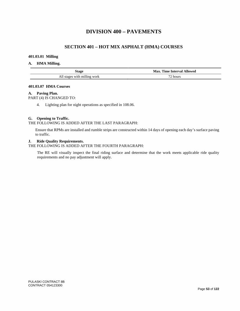
PULASKI CONTRACT 8B CONTRACT 054123300
Page 53 of 122
DIVISION 400 – PAVEMENTS
SECTION 401 – HOT MIX ASPHALT (HMA) COURSES
401.03.01 Milling
A. HMA Milling.
Stage Max. Time Interval Allowed All stages with milling work 72 hours
401.03.07 HMA Courses
A. Paving Plan. PART (4) IS CHANGED TO:
4. Lighting plan for night operations as specified in 108.06.
G. Opening to Traffic. THE FOLLOWING IS ADDED AFTER THE LAST PARAGRAPH:
Ensure that RPMs are installed and rumble strips are constructed within 14 days of opening each day’s surface paving to traffic.
J. Ride Quality Requirements. THE FOLLOWING IS ADDED AFTER THE FOURTH PARAGRAPH:
The RE will visually inspect the final riding surface and determine that the work meets applicable ride quality requirements and no pay adjustment will apply.
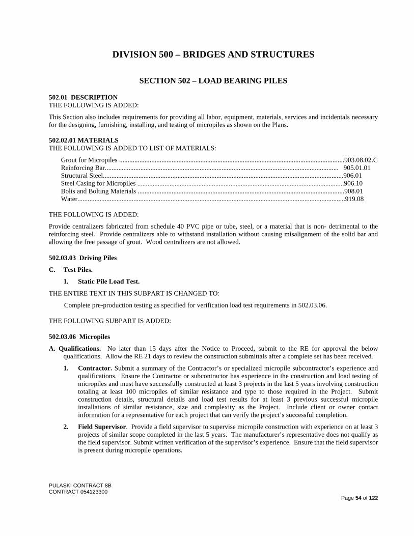
PULASKI CONTRACT 8B CONTRACT 054123300
Page 54 of 122
DIVISION 500 – BRIDGES AND STRUCTURES
SECTION 502 – LOAD BEARING PILES
502.01 DESCRIPTION THE FOLLOWING IS ADDED:
This Section also includes requirements for providing all labor, equipment, materials, services and incidentals necessary for the designing, furnishing, installing, and testing of micropiles as shown on the Plans. 502.02.01 MATERIALS THE FOLLOWING IS ADDED TO LIST OF MATERIALS:
Grout for Micropiles .....................................................................................................................................903.08.02.C Reinforcing Bar.......................................................................................................................................... 905.01.01 Structural Steel..............................................................................................................................................906.01 Steel Casing for Micropiles ..........................................................................................................................906.10 Bolts and Bolting Materials ..........................................................................................................................908.01 Water..............................................................................................................................................................919.08
THE FOLLOWING IS ADDED:
Provide centralizers fabricated from schedule 40 PVC pipe or tube, steel, or a material that is non- detrimental to the reinforcing steel. Provide centralizers able to withstand installation without causing misalignment of the solid bar and allowing the free passage of grout. Wood centralizers are not allowed.
502.03.03 Driving Piles
C. Test Piles.
1. Static Pile Load Test.
THE ENTIRE TEXT IN THIS SUBPART IS CHANGED TO:
Complete pre-production testing as specified for verification load test requirements in 502.03.06. THE FOLLOWING SUBPART IS ADDED:
502.03.06 Micropiles
A. Qualifications. No later than 15 days after the Notice to Proceed, submit to the RE for approval the below qualifications. Allow the RE 21 days to review the construction submittals after a complete set has been received.
1. Contractor. Submit a summary of the Contractor’s or specialized micropile subcontractor’s experience and qualifications. Ensure the Contractor or subcontractor has experience in the construction and load testing of micropiles and must have successfully constructed at least 3 projects in the last 5 years involving construction totaling at least 100 micropiles of similar resistance and type to those required in the Project. Submit construction details, structural details and load test results for at least 3 previous successful micropile installations of similar resistance, size and complexity as the Project. Include client or owner contact information for a representative for each project that can verify the project’s successful completion.
2. Field Supervisor. Provide a field supervisor to supervise micropile construction with experience on at least 3 projects of similar scope completed in the last 5 years. The manufacturer’s representative does not qualify as the field supervisor. Submit written verification of the supervisor’s experience. Ensure that the field supervisor is present during micropile operations.
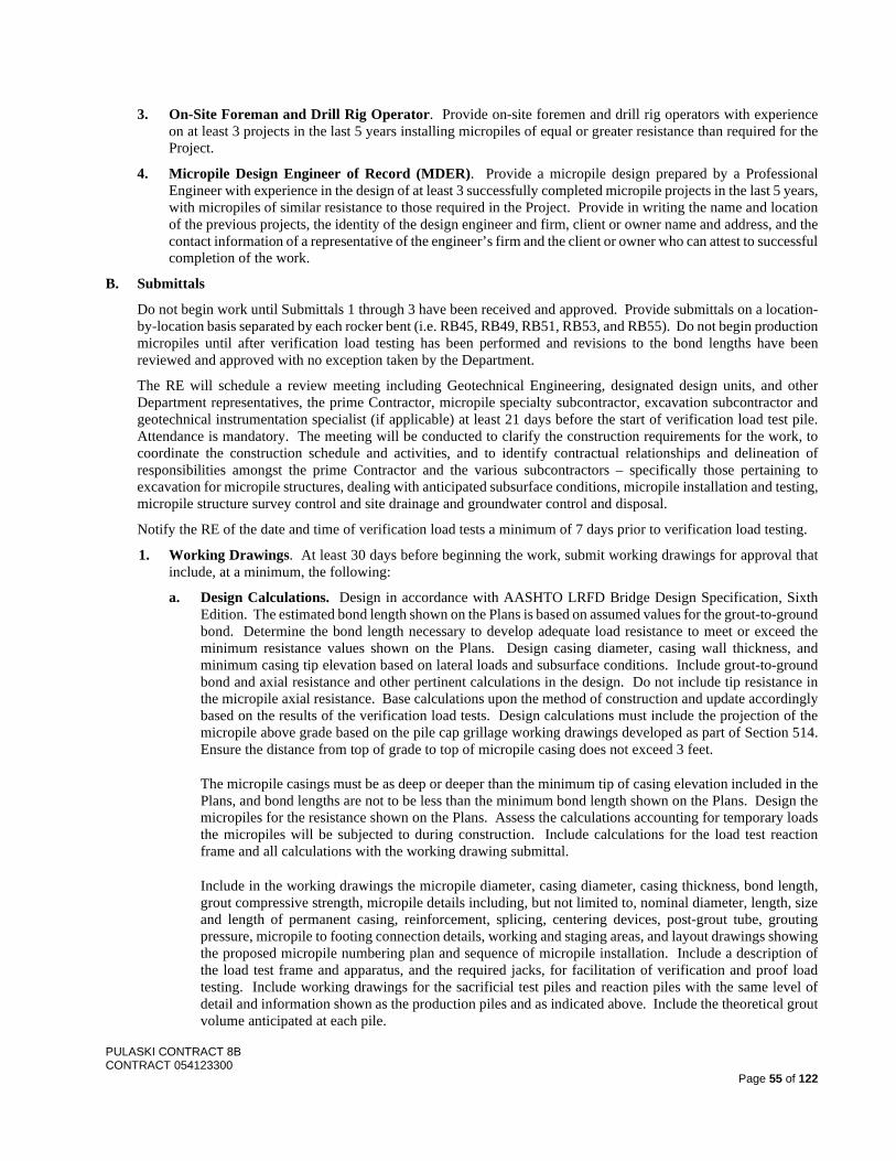
PULASKI CONTRACT 8B CONTRACT 054123300
Page 55 of 122
3. On-Site Foreman and Drill Rig Operator. Provide on-site foremen and drill rig operators with experience on at least 3 projects in the last 5 years installing micropiles of equal or greater resistance than required for the Project.
4. Micropile Design Engineer of Record (MDER). Provide a micropile design prepared by a Professional Engineer with experience in the design of at least 3 successfully completed micropile projects in the last 5 years, with micropiles of similar resistance to those required in the Project. Provide in writing the name and location of the previous projects, the identity of the design engineer and firm, client or owner name and address, and the contact information of a representative of the engineer’s firm and the client or owner who can attest to successful completion of the work.
B. Submittals
Do not begin work until Submittals 1 through 3 have been received and approved. Provide submittals on a location-by-location basis separated by each rocker bent (i.e. RB45, RB49, RB51, RB53, and RB55). Do not begin production micropiles until after verification load testing has been performed and revisions to the bond lengths have been reviewed and approved with no exception taken by the Department.
The RE will schedule a review meeting including Geotechnical Engineering, designated design units, and other Department representatives, the prime Contractor, micropile specialty subcontractor, excavation subcontractor and geotechnical instrumentation specialist (if applicable) at least 21 days before the start of verification load test pile. Attendance is mandatory. The meeting will be conducted to clarify the construction requirements for the work, to coordinate the construction schedule and activities, and to identify contractual relationships and delineation of responsibilities amongst the prime Contractor and the various subcontractors – specifically those pertaining to excavation for micropile structures, dealing with anticipated subsurface conditions, micropile installation and testing, micropile structure survey control and site drainage and groundwater control and disposal.
Notify the RE of the date and time of verification load tests a minimum of 7 days prior to verification load testing.
1. Working Drawings. At least 30 days before beginning the work, submit working drawings for approval that include, at a minimum, the following:
a. Design Calculations. Design in accordance with AASHTO LRFD Bridge Design Specification, Sixth Edition. The estimated bond length shown on the Plans is based on assumed values for the grout-to-ground bond. Determine the bond length necessary to develop adequate load resistance to meet or exceed the minimum resistance values shown on the Plans. Design casing diameter, casing wall thickness, and minimum casing tip elevation based on lateral loads and subsurface conditions. Include grout-to-ground bond and axial resistance and other pertinent calculations in the design. Do not include tip resistance in the micropile axial resistance. Base calculations upon the method of construction and update accordingly based on the results of the verification load tests. Design calculations must include the projection of the micropile above grade based on the pile cap grillage working drawings developed as part of Section 514. Ensure the distance from top of grade to top of micropile casing does not exceed 3 feet.
The micropile casings must be as deep or deeper than the minimum tip of casing elevation included in the Plans, and bond lengths are not to be less than the minimum bond length shown on the Plans. Design the micropiles for the resistance shown on the Plans. Assess the calculations accounting for temporary loads the micropiles will be subjected to during construction. Include calculations for the load test reaction frame and all calculations with the working drawing submittal.
Include in the working drawings the micropile diameter, casing diameter, casing thickness, bond length, grout compressive strength, micropile details including, but not limited to, nominal diameter, length, size and length of permanent casing, reinforcement, splicing, centering devices, post-grout tube, grouting pressure, micropile to footing connection details, working and staging areas, and layout drawings showing the proposed micropile numbering plan and sequence of micropile installation. Include a description of the load test frame and apparatus, and the required jacks, for facilitation of verification and proof load testing. Include working drawings for the sacrificial test piles and reaction piles with the same level of detail and information shown as the production piles and as indicated above. Include the theoretical grout volume anticipated at each pile.
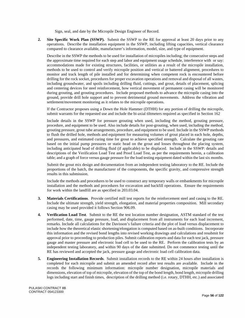
PULASKI CONTRACT 8B CONTRACT 054123300
Page 56 of 122
Sign, seal, and date by the Micropile Design Engineer of Record.
2. Site Specific Work Plan (SSWP). Submit the SSWP to the RE for approval at least 20 days prior to any operations. Describe the installation equipment in the SSWP, including lifting capacities, vertical clearance compared to clearance available, manufacturer’s information, model, size, and type of equipment.
Describe in the SSWP the methods to be used for installation of micropiles including; the consecutive steps and the approximate time required for each step and labor and equipment usage schedule, interference with or say: accommodations made for existing structures, facilities, or utilities as a result of the micropile installation, methods to be used to control and verify micropile position and vertical or battered alignment, procedures to monitor and track length of pile installed and for determining when competent rock is encountered before drilling for the rock socket, procedures for proper excavation operations and removal and disposal of all wastes, including groundwater, and spoils including drilling fluid, cuttings, and grout, details of placement, splicing and centering devices for steel reinforcement, how vertical movement of permanent casing will be monitored during grouting, and grouting procedures. Include proposed methods to advance the micropile casing into the ground, provide drill hole support and to prevent detrimental ground movements. Address the vibration and settlement/movement monitoring as it relates to the micropile operations.
If the Contractor proposes using a Down the Hole Hammer (DTHH) for any portion of drilling the micropile, submit warrants for the requested use and include the bi-axial tiltmeters required as specified in Section 162
Include details in the SSWP for pressure grouting when used, including the method, grouting pressure, procedure, and equipment to be used. Also include details for post-grouting, when used, including the method, grouting pressure, grout tube arrangements, procedure, and equipment to be used. Include in the SSWP methods to flush the drilled hole, methods and equipment for measuring volumes of grout placed in each hole, depths, and pressures, and estimated curing time for grout to achieve specified strength. Calculate the grouting rate based on the initial pump pressures or static head on the grout and losses throughout the placing system, including anticipated head of drilling fluid (if applicable) to be displaced. Include in the SSWP: details and descriptions of the Verification Load Test and Proof Load Test, as per the requirements herein, a calibration table; and a graph of force versus gauge pressure for the load testing equipment dated within the last six months.
Submit the grout mix design and documentation from an independent testing laboratory to the RE. Include the proportions of the batch, the manufacturer of the components, the specific gravity, and compressive strength results in this submission.
Include the methods and procedures to be used to construct any temporary walls or embankments for micropile installation and the methods and procedures for excavation and backfill operations. Ensure the requirements for work within the landfill are as specified in 203.03.04.
3. Materials Certifications. Provide certified mill test reports for the reinforcement steel and casing to the RE. Include the ultimate strength, yield strength, elongation, and material properties composition. Mill secondary casing may be used provided it follows Section 906.09.
4. Verification Load Test. Submit to the RE the test location number designation, ASTM standard of the test performed, date, time, gauge pressure, load, and displacement from all instruments for each load increment, remarks. Include all calculations for the Davisson’s failure criteria and the plot of load versus displacement to include how the theoretical elastic shortening/elongation is computed based on as-built conditions. Incorporate this information and the revised bond lengths into revised working drawings and calculations and resubmit for approval prior to proceeding to production piles. Submit calibration reports and data for each test jack, pressure gauge and master pressure and electronic load cell to be used to the RE. Perform the calibration tests by an independent testing laboratory, and within 90 days of the date submitted. Do not commence testing until the RE has reviewed and accepted the jack, pressure gauge and electronic load cell calibration data.
5. Engineering Installation Records. Submit installation records to the RE within 24 hours after installation is completed for each micropile and submit an amended record after test results are available. Include in the records the following minimum information: micropile number designation, micropile materials and dimensions, elevation of top of micropile, elevation of the top of the bond length, bond length, micropile drilling logs including start and finish times, description of the drilling method (i.e. rotary, DTHH, etc.) and associated
PULASKI CONTRACT 8B CONTRACT 054123300
Page 57 of 122
depths, final tip elevation, cut-off elevation, design factored resistance, type, length, and size of reinforcement steel, description of unusual installation behavior or conditions, grout pressures attained if pressure grouting or post-grouting is performed, post-grouting details when performed, grout quantities pumped, theoretical grout volume, grout specific gravities, grout compressive strengths, proof load test results, horizontal deviation from plan location, vertical inclination, and time required for each operation. It is preferable that this data be recorded with an automatic monitoring system and overseen by the approved on-site foreman. Include the proof load test results with the same information and requirements as stated in Submittal 4 for the Verification Load Test.
6. As-Built Plans. Prepare and submit to the RE upon the completion of all the micropile installation, as-built drawings showing the location of the micropiles, their depth and inclination from vertical, their designed factored resistance, and cross-sectional properties.
C. Load Tests
1. Verification Load Tests.
Perform axial tension and lateral verification load testing in accordance with AASHTO LRFD Bridge Design Specifications Article 10.9.3.5.4 (ASTM D3689 for tension and ASTM D3966 for lateral) using the “Quick Load Test Method”. Do not exceed 80% of the structural resistance.
Perform verification load testing on the piles as shown on the Plans and the approved working drawings. Perform verification load tests on non-production sacrificial micropiles, installed with the same section, materials, and installation methods as proposed for production micropiles. If the verification pile needs to be upsized structurally to achieve the required verification load testing acceptance criteria, then include this in the working drawings and design calculations and upsize all production piles similarly. Include sacrificial reaction piles as required and as shown on the Plans for verification load testing. The use of production piles as reaction piles for verification load testing is not permitted. Conduct axial load testing prior to lateral load testing. During verification axial load testing, exercise care not to permanently damage the pile in such a way that reduces its lateral capacity. Do not include plunge length in verification load test micropiles. Identify end bearing capacity and do not include in the resistance.
Use the Davisson’s Failure Criteria as defined in AASHTO LRFD Bridge Design Specifications Article 10.7.3.8.2 for axial verification load test criteria. Ensure that test piles have a creep rate at the end of the 0.975 factored design load (FDL) increment that is less than 0.04 inch per log cycle time (1 to 10 minutes) or 0.08 inch per log cycle time (6 to 60 minutes) and has a linear or decreasing creep rate.
Perform the axial verification load test as specified in Table 502.03.06-1. Record and plot pile head movement at each increment. Perform the verification load test to the maximum Factored Design Load (FDL) of all piles located in that particular span.
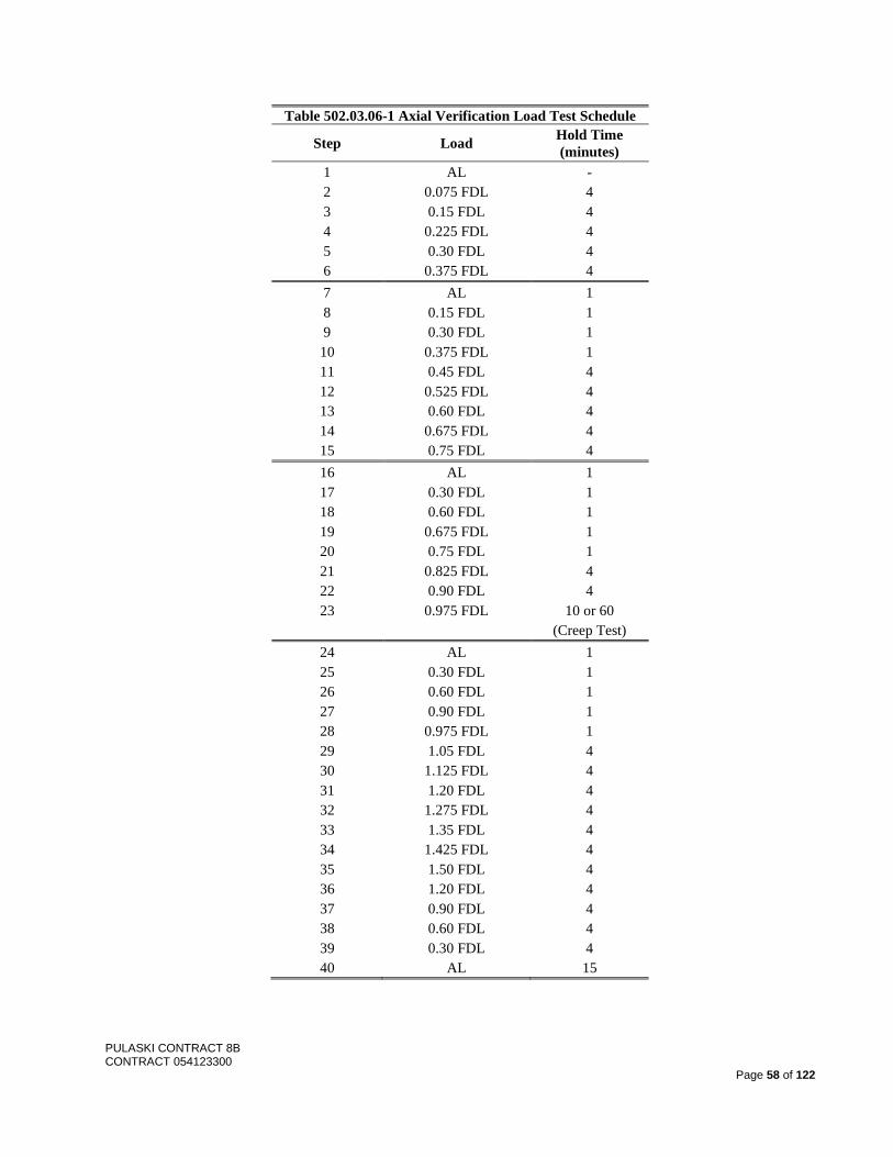
PULASKI CONTRACT 8B CONTRACT 054123300
Page 58 of 122
Table 502.03.06-1 Axial Verification Load Test Schedule
Step Load Hold Time (minutes)
1 AL - 2 0.075 FDL 4 3 0.15 FDL 4 4 0.225 FDL 4 5 0.30 FDL 4 6 0.375 FDL 4 7 AL 1 8 0.15 FDL 1 9 0.30 FDL 1 10 0.375 FDL 1 11 0.45 FDL 4 12 0.525 FDL 4 13 0.60 FDL 4 14 0.675 FDL 4 15 0.75 FDL 4 16 AL 1 17 0.30 FDL 1 18 0.60 FDL 1 19 0.675 FDL 1 20 0.75 FDL 1 21 0.825 FDL 4 22 0.90 FDL 4 23 0.975 FDL 10 or 60
(Creep Test) 24 AL 1 25 0.30 FDL 1 26 0.60 FDL 1 27 0.90 FDL 1 28 0.975 FDL 1 29 1.05 FDL 4 30 1.125 FDL 4 31 1.20 FDL 4 32 1.275 FDL 4 33 1.35 FDL 4 34 1.425 FDL 4 35 1.50 FDL 4 36 1.20 FDL 4 37 0.90 FDL 4 38 0.60 FDL 4 39 0.30 FDL 4 40 AL 15
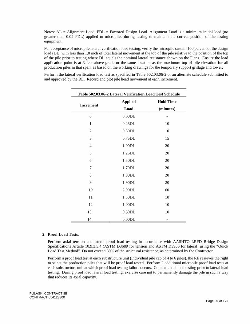
PULASKI CONTRACT 8B CONTRACT 054123300
Page 59 of 122
Notes: AL = Alignment Load, FDL = Factored Design Load. Alignment Load is a minimum initial load (no greater than 0.04 FDL) applied to micropiles during testing to maintain the correct position of the testing equipment.
For acceptance of micropile lateral verification load testing, verify the micropile sustain 100 percent of the design load (DL) with less than 1.0 inch of total lateral movement at the top of the pile relative to the position of the top of the pile prior to testing where DL equals the nominal lateral resistance shown on the Plans. Ensure the load application point is at 3 feet above grade or the same location as the maximum top of pile elevation for all production piles in that span; as based on the working drawings for the temporary support grillage and tower.
Perform the lateral verification load test as specified in Table 502.03.06-2 or an alternate schedule submitted to and approved by the RE. Record and plot pile head movement at each increment.
Table 502.03.06-2 Lateral Verification Load Test Schedule
Increment Applied
Load
Hold Time
(minutes)
0 0.00DL -
1 0.25DL 10
2 0.50DL 10
3 0.75DL 15
4 1.00DL 20
5 1.25DL 20
6 1.50DL 20
7 1.70DL 20
8 1.80DL 20
9 1.90DL 20
10 2.00DL 60
11 1.50DL 10
12 1.00DL 10
13 0.50DL 10
14 0.00DL -
2. Proof Load Tests.
Perform axial tension and lateral proof load testing in accordance with AASHTO LRFD Bridge Design Specifications Article 10.9.3.5.4 (ASTM D3689 for tension and ASTM D3966 for lateral) using the “Quick Load Test Method”. Do not exceed 80% of the structural resistance, as determined by the Contractor.
Perform a proof load test at each substructure unit (individual pile cap of 4 to 6 piles), the RE reserves the right to select the production piles that will be proof load tested. Perform 2 additional micropile proof load tests at each substructure unit at which proof load testing failure occurs. Conduct axial load testing prior to lateral load testing. During proof load lateral load testing, exercise care not to permanently damage the pile in such a way that reduces its axial capacity.
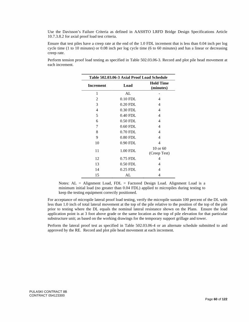
PULASKI CONTRACT 8B CONTRACT 054123300
Page 60 of 122
Use the Davisson’s Failure Criteria as defined in AASHTO LRFD Bridge Design Specifications Article 10.7.3.8.2 for axial proof load test criteria.
Ensure that test piles have a creep rate at the end of the 1.0 FDL increment that is less than 0.04 inch per log cycle time (1 to 10 minutes) or 0.08 inch per log cycle time (6 to 60 minutes) and has a linear or decreasing creep rate.
Perform tension proof load testing as specified in Table 502.03.06-3. Record and plot pile head movement at each increment.
Table 502.03.06-3 Axial Proof Load Schedule
Increment Load Hold Time (minutes)
1 AL - 2 0.10 FDL 4 3 0.20 FDL 4 4 0.30 FDL 4 5 0.40 FDL 4 6 0.50 FDL 4 7 0.60 FDL 4 8 0.70 FDL 4 9 0.80 FDL 4 10 0.90 FDL 4
11 1.00 FDL 10 or 60 (Creep Test)
12 0.75 FDL 4 13 0.50 FDL 4 14 0.25 FDL 4 15 AL 4
Notes: AL = Alignment Load, FDL = Factored Design Load. Alignment Load is a minimum initial load (no greater than 0.04 FDL) applied to micropiles during testing to keep the testing equipment correctly positioned.
For acceptance of micropile lateral proof load testing, verify the micropile sustain 100 percent of the DL with less than 1.0 inch of total lateral movement at the top of the pile relative to the position of the top of the pile prior to testing where the DL equals the nominal lateral resistance shown on the Plans. Ensure the load application point is at 3 foot above grade or the same location as the top of pile elevation for that particular substructure unit; as based on the working drawings for the temporary support grillage and tower.
Perform the lateral proof test as specified in Table 502.03.06-4 or an alternate schedule submitted to and approved by the RE. Record and plot pile head movement at each increment.
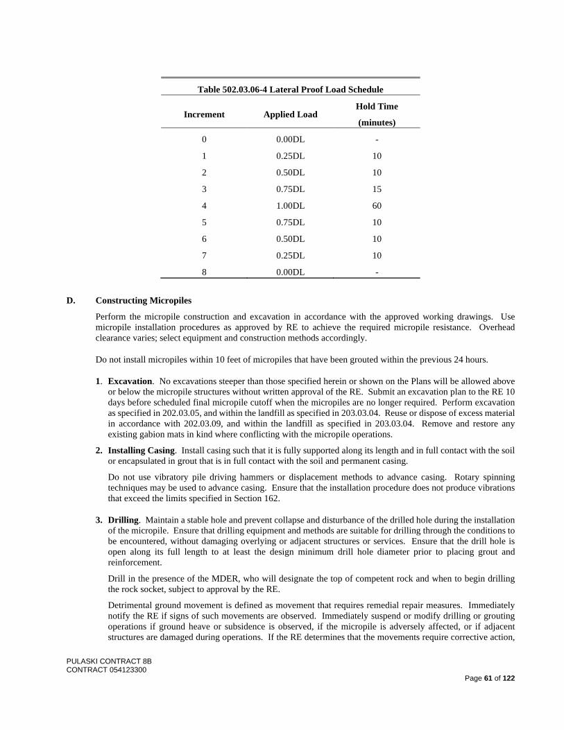
PULASKI CONTRACT 8B CONTRACT 054123300
Page 61 of 122
Table 502.03.06-4 Lateral Proof Load Schedule
Increment Applied Load Hold Time
(minutes)
0 0.00DL -
1 0.25DL 10
2 0.50DL 10
3 0.75DL 15
4 1.00DL 60
5 0.75DL 10
6 0.50DL 10
7 0.25DL 10
8 0.00DL -
D. Constructing Micropiles
Perform the micropile construction and excavation in accordance with the approved working drawings. Use micropile installation procedures as approved by RE to achieve the required micropile resistance. Overhead clearance varies; select equipment and construction methods accordingly.
Do not install micropiles within 10 feet of micropiles that have been grouted within the previous 24 hours.
1. Excavation. No excavations steeper than those specified herein or shown on the Plans will be allowed above or below the micropile structures without written approval of the RE. Submit an excavation plan to the RE 10 days before scheduled final micropile cutoff when the micropiles are no longer required. Perform excavation as specified in 202.03.05, and within the landfill as specified in 203.03.04. Reuse or dispose of excess material in accordance with 202.03.09, and within the landfill as specified in 203.03.04. Remove and restore any existing gabion mats in kind where conflicting with the micropile operations.
2. Installing Casing. Install casing such that it is fully supported along its length and in full contact with the soil or encapsulated in grout that is in full contact with the soil and permanent casing.
Do not use vibratory pile driving hammers or displacement methods to advance casing. Rotary spinning techniques may be used to advance casing. Ensure that the installation procedure does not produce vibrations that exceed the limits specified in Section 162.
3. Drilling. Maintain a stable hole and prevent collapse and disturbance of the drilled hole during the installation of the micropile. Ensure that drilling equipment and methods are suitable for drilling through the conditions to be encountered, without damaging overlying or adjacent structures or services. Ensure that the drill hole is open along its full length to at least the design minimum drill hole diameter prior to placing grout and reinforcement.
Drill in the presence of the MDER, who will designate the top of competent rock and when to begin drilling the rock socket, subject to approval by the RE.
Detrimental ground movement is defined as movement that requires remedial repair measures. Immediately notify the RE if signs of such movements are observed. Immediately suspend or modify drilling or grouting operations if ground heave or subsidence is observed, if the micropile is adversely affected, or if adjacent structures are damaged during operations. If the RE determines that the movements require corrective action,
PULASKI CONTRACT 8B CONTRACT 054123300
Page 62 of 122
submit corrective actions necessary to stop the movement and perform repairs. Complete all repairs as directed by the RE.
Use of drilling fluid containing bentonite is not allowed. Provide temporary casing or other approved methods of micropile drill hole support in unstable ground to permit the micropile shaft construction. Maintain full contact between the soil and the outer casing during drilling. Withdrawal of the casing during drilling, or failure to fully support the hole prior to introduction of the grout into the hole is not permitted. Positive circulation or flushing, a method of progressing and cleaning a hole wherein water is injected into the hole and returned upward along the outside of the drill casing, will not be allowed. Exercise caution to prevent over excavation or heaving.
Always keep the drill tool no further than 6 inches ahead of the end of the drill casing. Use a cutting shoe for advancing the casing, with a shoe diameter less than the outer diameter of the casing plus 0.25 inches. Control drill fluid and cuttings by diverters, or other methods approved by the RE, that produce a closed system allowing all for separation of drill spoil fluids and solids for disposal. Remove and dispose of all waste material including groundwater, spoils, drilling fluid, cuttings, and grout as specified in Section 202.
Always use drilling casing in full contact with the bored hole sides. Do not use casing spinning, sudden or rapid withdrawal and plunge or similar operating procedures that may result in disturbance, collapse or an unsupported drill hole during micropile installation.
If obstructions are encountered during micropile installation, advance the bore hole to the required depth using a method approved by the RE. Use of drop-type impact hammers or blasting will not be permitted.
Do not use a down-the-hole hammer (DTHH) unless approved in writing by the RE. The use of the DTHH will not be allowed within 20 feet of micropiles that were grouted within the previous 24 hours. The DTHH will not be allowed for drilling through soil. The DTHH will only be allowed for advancing through rock or obstructions after demonstrating the inadequacy of other drilling methods (i.e. rotary). When using the DTHH and disturbance to freshly grouted micropiles greater than 20 feet away is observed, stop using the DTHH. Before resuming DTHH operation, demonstrate that completed micropiles are not disturbed by operations. If the following adverse conditions are observed, the permission to use the DTHH will not be allowed until remedial actions are provided to eliminate the adverse effects.
1. Communication of air, water, or soil between micropiles or between micropiles and the existing foundations.
2. Exceedances of the vibration or displacement monitoring requirements in Section 162 and the approved Vibration and Settlement/Movement Control Plan Working Drawings.
3. Adverse effects on adjacent structures or utilities are observed If communication is observed, complete additional proof load tests on the effected piles if requested by the RE. If the Contractor is required to switch from the DTHH to a roller bit, complete any additional verification or proof load test in tension as requested by the RE. Complete all required remedial measures to the satisfaction of the RE.
Control the procedures and operations to preclude undermining, disturbance, or settlement of adjacent structures or utilities. If disturbance occurs, halt operations and modify the equipment and procedures so that no further disturbance occurs. Repair disturbance to the satisfaction of the RE.
Control the procedures and operations to prevent the soil at the bottom of the hole from flowing into the hole. Always maintain the fluid level inside the hole above the ground water level during installation and cleaning. Monitor and record the rate of fluid flow used to progress the hole.
Manage the control, storage and disposal of wastes and spoils in accordance with 202.03.05 and 202.03.09, and
PULASKI CONTRACT 8B CONTRACT 054123300
Page 63 of 122
specific requirements within the landfill. Contain any slurry and groundwater generated from micropile operations in accordance with the approved groundwater treatment plan specified in 202
Do not pre-drill more than one hole prior to grouting unless approved by the RE. Do not leave a hole open overnight. Cap or cover all incomplete micropiles that are in progress during overnight or weekend breaks for safety and to prevent objects from falling in.
Complete drilling and install steel casing to the approved depths. Clean hole with water before installing reinforcement steel or grout and until all contaminated water, drilling fluid, and cuttings are removed and a clean return is observed. Cleaning the hole with compressed air will not be permitted.
4. Placing Reinforcement. When a bearing plate and nut are required to be threaded onto the top end of reinforcement bars for the micropile top to pile cap anchorage, the threading may be continuous spiral deformed ribbing provided by the bar deformations (e.g. Dywidag or Williams continuous threadbars) or cut into the reinforcement bar. If threads are cut into the reinforcement bar, provide the next larger bar number designation from that shown on the approved working drawings. If required, use bar tendon couplers capable of developing the ultimate tensile strength of the bars without evidence of failure, and size such that they allow passage of grout between the casing and coupler. Place couplers at least 15 feet below the proposed top of micropile elevation. Reinforcement may be placed either prior to grouting or into the grout filled drill hole before temporary casing (if used) is withdrawn. Use reinforcement free of deleterious substances such as soil, mud, grease or oil that might contaminate the grout or impair bond. If micropile cages and reinforcement groups are used, ensure that they are adequate to withstand the installation and grouting process and the withdrawal of the drill casings without damage or disturbance. Place reinforcement steel bars in each micropile as shown on the working drawings.
Check micropile top elevations and adjust all installed micropiles to the elevations shown on the temporary support tower working drawings. Provide centralizers at maximum 10-foot spacing. Locate the upper and lower most centralizer 2 feet from the top and bottom of the micropile. Use centralizers that allow free flow of grout without misalignment of the reinforcement and casing. Lower the central reinforcement with centralizers into the stabilized drill hole and set. Place the reinforcement steel into the drill hole to the desired depth without force. Do not drive partially inserted reinforcement or force reinforcement into the hole. Re-drill the hole and reinsert reinforcement steel when necessary to facilitate insertion.
Align casing and reinforcement to be spliced in a manner to avoid eccentricity or angle between the axis of the two lengths to be spliced. Locate threaded pipe casing joints at least two casing diameters (outside diameter) from a splice in any reinforcement bar. Stagger multiple bars and bar splices at least 1 foot.
5. Grouting. If post grouting is proposed, perform load tests on post grouted micropiles approved by the RE.
Place grout by means of a tremie pipe extending to the bottom of the micropile and pump upward to displace the fluid in the hole until undiluted grout returns at the top of the micropile. Continue the above operation until the grout coming out has the same consistency as the grout being pumped into the micropile through the tremie pipe.
Tremie grout micropiles the same day the bond length is drilled or within 3 hours of verifying the bond zone length. Construction cold joints will not be permitted in the grouted concrete column.
Apply pressure by attaching a pressure cap to the top of the drill casing or drilling head and injecting additional grout into the casing under controlled pressure. Calculate the minimum pump pressure at the top of the steel casing and include the minimum pressure in the submittal. Provide a pressure gauge for grout pressure monitoring capable of measuring pressure of at least 200 pounds per square inch or twice the actual grout pressure to be used, whichever is greater.
Closely control the rate of drill casing removal so that the grout level remains at the top of the casing. Perform pressure grouting and simultaneous casing withdrawal until the required bond length is achieved. Maintain a positive flow of grout into the micropile after withdrawal of each length of casing. After the required bond
PULASKI CONTRACT 8B CONTRACT 054123300
Page 64 of 122
length is achieved, push the permanent casing back down a minimum of the plunge length shown on the Plans into the grout. Ensure that the bond length shown in the approved working drawings is provided below the tip of casing.
Calculate and record the initial volume of grout used to fill the hole. Record the grout pressures and volume pumped during pressure grouting. Maintain the grout level at the top of the micropile until the grout has set. Ensure that grout is flush with the top of the micropile casing prior to installing pile cap attachments.
Use the same procedure, equipment, and materials used to perform post-grouting for the verification test micropiles for production micropiles. Perform post-grouting at least 48 hours after the primary grouting or after the grout for the micropile has hardened. Pump grout under pressure into a post-grout tube cast into the micropile until the grout exits the post-grout tube one port at a time. Isolate the port using a packer system.
Record the pumping pressure and the volume pumped through each port.
6. Construction Tolerances. Install the micropiles so that the center of the micropile does not vary from the plan location by more than 3 inches. Do not allow the micropile to vary from the vertical (plumb) or approved batter by more than 1/4 inch per foot.
If the micropile is post-grouted, monitor the elevation of the micropile top during post-grouting. Do not permit micropile uplift to exceed 1/4 inch.
Do not install centerline of reinforcement steel bar more than 0.5 inch from the location shown on the Plans.
7. Micropile Acceptance Criteria. The RE will reject micropiles because of damage, failure to advance through obstructions, mis-location, misalignment, failure to meet load test acceptance criteria, failure to install the micropile using the approved equipment and procedures, or failure to install the micropile to the proper depth and required bond lengths. Submit a plan to the RE for approval to correct the problem and prevent reoccurrence. Repair or augment the micropile to the satisfaction of the RE. To mitigate unaccepted micropiles, the Contractor may be required to provide additional micropiles or supplement micropiles. Payment will not be made for a rejected micropile until such time that the micropile is repaired or augmented to the acceptance of the RE.
8. Inspection. Ensure that the on-site foreman performs the inspection and records the information required. Complete down hole closed circuit television (CCTV) inspection of all rock sockets and provide a DVD recording with an audio narrative by the on-site foreman. Ensure that the MDER and RE are present and able to view the CCTV inspection. Provide a copy of all down hole televised inspections to the RE on DVD.
9. Grout Testing. Determine grout consistency as measured by grout density according to ASTM C188 the same time grout cubes are taken, as described herein, and one additional time per micropile as randomly selected by the MDER. Obtain RE approval for recommended sampling. Retain an independent testing laboratory, with Cement and Concrete Reference Laboratory (CCRL) certification, to take the grout samples, test grout density on site and to perform the grout sampling and testing.
Take four sets of grout samples from each micropile at the time of grouting of micropiles. Submit control sample selection recommended by the MDER to the RE for approval. Provide a constructed curing box that meets the requirements of the independent testing company. Ensure that the testing company molds, cures, and tests in accordance with ASTM C109M and ASTM C1107 until the samples reach the design compressive strength. Perform compressive strength and density tests of grout samples for each micropile at 24 hours, 3 days, 7 days, and 28 days until the design compressive strength is met.
Modify the proportions of the mix subject to the approval of the RE and retest samples until the requirements are met. Install replacement micropiles as required at no additional cost if the required design strength is not attained in 28 days.
Submit to the RE compressive strength and density test results within 5 days of each test.
PULASKI CONTRACT 8B CONTRACT 054123300
Page 65 of 122
Modify the mix design if a) an excessive volume of grout is lost from a micropile hole into voids, and b) if the rebar and centralizers encounter excessive resistance during installation.
Use the same volume and the same whole number of bags of cement for each batch of grout, unless a modification is approved by the RE.
If agitated continuously, the grout may be held in the mixer or agitator for a period not exceeding 3 hours at temperatures below 70 °F and for a period not exceeding 2 hours at higher temperatures.
If there is a lapse in pumping of the grout, the grout is to be re-circulated through the pump or through the mixer drum or agitator and pump. Re-tempering of grout will not be permitted.
10. Cut Off and Restoration. Excavate as necessary and cut off the top of the micropiles as shown on the Plans. Restore disturbed areas to their original condition
502.04 MEASUREMENT AND PAYMENT THE FOLLOWING ITEM IS ADDED:
Item Pay Unit MICROPILES, __________ LINEAR FOOT
THE SIXTH PARAGRAPH IS CHANGED TO:
The Department will make payment for furnishing, installing, and testing of each combined set of pre-production sacrificial test micropiles and sacrificial reaction piles shown on the Plans for verification load testing under STATIC PILE LOAD TEST. THE FOLLOWING IS ADDED:
The Department will measure the length of micropiles installed by total length of linear foot tested and accepted, based on the following:
Type A in rock - from the pile tip to the approved top of component rock. Type A in soil - from the approved top of component rock top to the top of the pile casing elevations as shown on the approved temporary support tower working drawings for each tower, not to exceed 3 feet above grade. Type B in soil - from the pile tip to the top of the pile casing elevations as shown on the approved temporary support tower working drawings for each tower, not to exceed 3 feet above grade.
The Department will make payment for storage, treatment, and disposal of groundwater as specified in 202.04.
The Department will make payment for restoration of the existing ground within the landfill under Span 56 as specified in 203.04
SECTION 504 – STRUCTURAL CONCRETE 504.02 MATERIALS
504.02.01 Materials
THE FOLLOWING IS ADDED TO THE LIST OF MATERIALS:
Non-Shrink Grout ...................................................................................................................................... 903.08.02.A Stainless Steel Reinforcement ……………………………………………………………………… ........ 905.01.06 Adhesive Anchor Bolt Systems ..................................................................................................................... 908.01.04 Epoxy Bonding Compound ................................................................................................................................. 919.07
PULASKI CONTRACT 8B CONTRACT 054123300
Page 66 of 122
504.03.01 Reinforcement Steel
A. Handling. THE FOLLOWING IS ADDED AFTER THE FIRST PARAGRAPH:
Prior to shipping, ensure that all chains and steel bands will not come into direct contact with the stainless steel reinforcement bars. Place wood or other soft materials, such as thick cardboard, under the tie-downs. Alternatively, use nylon or polypropylene straps to secure the stainless steel reinforcement bars. When bundles of reinforcement steel and stainless steel reinforcement bars must be shipped one on top of the other, load the stainless steel bars on top. Use wooden spacers to separate the two materials. Do not use carbon steel tools, chains, slings, etc. when fabricating or handling stainless steel reinforcement bars. Use only nylon or polypropylene slings.
B. Storing THE FOLLOWING IS ADDED AFTER THE SECOND PARAGRAPH:
Outside storage of stainless bars is acceptable. Cover the stainless steel reinforcement bars with tarpaulins. Store stainless steel reinforcement bars off the ground or shop floor on wooden supports. Do not store stainless steel reinforcement bars at the work site for more than 60 days unless approved by the RE.
E. Placing and Fastening. THE FOLLOWING IS ADDED:
Provide tie wires meeting the requirements of 905.01.06 for blocks supporting stainless steel reinforcement. Fabricate metal chairs and continuous metal supports in contact with stainless steel reinforcement from stainless steel conforming to the requirements of ASTM A 493, Type 316, UNS number S31600; or Type 316L, UNS number S31603. Do not tie stainless steel reinforcement to steel reinforcement. Direct contact is not acceptable. When stainless steel reinforcing or dowels must be near steel reinforcing, use nylon or polyethylene spacers to maintain a minimum 1 inch clearance between the two metals and bind them with nylon cable ties. Where insufficient space exists to maintain this minimum, either bar may be sleeved with a continuous polyethylene or nylon tube extending at least 1 inch in each direction past the point of closest contact between the two dissimilar bars.
Drill and grout reinforcing steel at the locations shown on the Plans.
F. Splices. THE FOLLOWING IS ADDED TO THE FIRST PARAGRAPH:
For stainless steel reinforcement, provide splice samples that meet the requirements of 905.01.06 to the RE for approval.
THE FOLLOWING SUBPART IS ADDED:
I. Drill and Grout Reinforcement Steel. Drill and grout reinforcement steel in holes for dowels with adhesive grout at the locations shown on the Plans and to the depth and diameter as shown on the Plans or as recommended by the adhesive anchor system manufacturer. Grout the dowels in place, using an adhesive anchor system to form a complete bond between the dowels and the concrete. Submit the proposed adhesive anchor system for approval at least 30 days before commencing the work. Include in the submittal the maximum tensile and shear capacity of the system after any applicable reductions for dowel spacing and concrete edge distance as determined by the anchoring system manufacturer. Also include the recommended embedment depth. Repair all damage caused by drilling and grouting operations.
504.03.02 Concrete C. Limitations of Placing. THE FOLLOWING IS ADDED BEFORE THE FIRST PARAGRAPH:
This Section is not applicable for High Performance Concrete (HPC), Lightweight Concrete. For Limitations of Placing HPC, Lightweight Concrete, see Section 504.03.02 Subpart K.
PULASKI CONTRACT 8B CONTRACT 054123300
Page 67 of 122
D. Placing and Consolidating Concrete.
2. Pumped Concrete. THE FOLLOWING IS ADDED:
If electing to place HPC, Lightweight Concrete by pump, perform a comprehensive field demonstration test with the approved mix design, manpower, and equipment to the satisfaction of the RE prior to placement. Demonstrate that all material acceptance requirements are achieved based on the approved placement plan.
G. Removal of Forms and Falsework. THE FOLLOWING IS ADDED:
Do not remove forms and falsework until the concrete obtains a compressive strength of 3000 pounds per square inch.
THE FOLLOWING SUBPART IS ADDED. K. Limitations of Placing (HPC, Lightweight Concrete).
At least 30 days before placing concrete, submit to the RE for approval a plan for hot and cold weather concreting. Include the method that will be used to ensure that the temperature of the concrete is between 50 and 90 °F during mixing and placing.
Do not place concrete when precipitation is imminent as determined by the RE. If it begins precipitating during concrete placement, the RE may direct the Contractor to suspend placement operations and protect the plastic concrete as specified in 504.03.02.I. If placement cannot be resumed within 30 minutes, the RE may direct the construction of a construction joint.
Ensure the HPC, Lightweight Concrete is not exposed to ambient temperatures lower than 40 °F during a time period of 28 days following placement under all circumstances. If the HPC, Lightweight Concrete is exposed to ambient temperatures below 40 °F without proper temperature protection during this time period, the RE will direct that the concrete be removed and replaced at no additional cost to the Department or Contract Time extension.
If, during the concrete placement or within the 24 hours preceding the scheduled concrete placement, the National Weather Service http://www.nws.noaa.gov/ locally forecasts the ambient temperature to be below 40 °F or above 75 °F during the scheduled concrete placement, curing period, or 28-day requirement, follow the appropriate temperature condition procedure. Do not place concrete when the ambient temperature is below 40 °F or above 100 °F. 1. Cold Weather Concreting. The RE will prohibit the placement of concrete when the ambient temperature is
below 40 °F, unless all surfaces in contact with the concrete placement are preheated to between 50 and 80 °F and access is provided for measuring the temperature of the in-place concrete. For access, establish a 1/2 inch diameter hole that is 6 inches deep at a 45 degree angle by placing a greased bolt through the forms prior to concrete placement.
Use one or more of the following protective measures to maintain the concrete temperature:
a. Insulated Forms. Before placing concrete, construct insulated forms to protect concrete. Ensure that the forms are free of ice, snow, and frost at time of placing concrete.
b. Insulated Blankets. Use insulated blankets to protect concrete. Place the blankets on top of polyethylene sheeting within 30 minutes of placing concrete.
c. Heating and Housing. Before placing concrete in the forms, provide housing for the section of concrete to be placed so that the temperatures specified can be maintained within the enclosure. Construct the enclosures to allow removal of forms and finishing of concrete surfaces without interruption of the heating.
Maintain the heating system to provide uniform heating within the enclosure. Ensure that the heating system has been operating so that the temperature of form surfaces, reinforcement steel and abutting construction to be in contact with the concrete is between 50 and 80 °F before placing the concrete.
PULASKI CONTRACT 8B CONTRACT 054123300
Page 68 of 122
Provide a sufficient number of back-up heaters at the Project Limits to maintain the temperature of the housing in the event of a breakdown of the primary heating system. In the event of a breakdown, operate the back-up heaters until the primary heating system is repaired.
Maintain the protective measures for at least 28 days. Ensure that the temperature of the concrete is maintained between 60 and 160 °F for 28 days after placement. The RE will check the temperature of the concrete in the established hole. If the temperature of the concrete falls below 60 °F within 28 days after placing, maintain the protective measures in place for an additional 5 days. If the temperature of the concrete rises above 160 °F, the RE may direct the forms to be loosened or protective measures to be removed. If the temperature of the concrete falls below 40 °F or rises above 180 °F within 28 days of placement, the RE will direct that the concrete be removed and replaced. After the concrete temperature has been maintained for 28 days at a minimum of 60 °F, ensure that the temperature of the concrete does not fall more than 10 °F in 12 hours.
2. Hot Weather Concreting. Follow provisions of section 504.03.02 (C).
504.04 MEASUREMENT AND PAYMENT THE FOLLOWING ITEM IS ADDED:
Item Pay Unit REINFORCEMENT STEEL, STAINLESS STEEL POUND
SECTION 506 – STRUCTURAL STEEL
506.01 DESCRIPTION THE FOLLOWING IS ADDED:
This Section also describes the requirements to furnish, erect, repair, retrofit and replace existing structural steel elements and members, including all work that use structural steel and miscellaneous metals and other materials.
506.02 MATERIALS THE FOLLOWING IS ADDED TO THE LIST OF MATERIALS:
Stainless Steel Plates ........................................................................................................................................... 906.01 Polytetrafluoroethylene (PTFE) Stainless Steel Surfaces ................................................................................... 906.01 Steel Putty ........................................................................................................................................................... 906.09 High Strength Steel Bolting Materials ................................................................................................................ 908.02 Stainless Steel Bolting Material .......................................................................................................................... 908.04
506.03.01 Structural Steel
A. Working Drawings. THE FIRST SENTENCE IS CHANGED TO:
Submit working drawings for certification for structural steel on the Broadway Ramp structure replacement and structural steel associated with all repair and retrofit types, including rocker bent replacements. Submit working drawings in separate packages for Span 44, Spans 45-56, and the Broadway Ramp replacement. Submit working drawings that include the following:
THE FOLLOWING IS ADDED:
Examine the structure with the RE to verify the work areas and determine exact work area limits. The RE may increase or decrease the repair areas based on the examination.
PULASKI CONTRACT 8B CONTRACT 054123300
Page 69 of 122
Perform detailed construction survey to verify and determine all dimensions, elevations, details, geometry and conditions as required for working drawing submittals, fabrication and construction of all work under this Contract including repair and retrofit work areas and new structural steel. Advise the RE at least 30 days in advance of submitting working drawings if an existing structural element or section loss is significantly different than shown on the Plans. Submit working drawings for structural steel and for each repair and retrofit location based on construction survey. Show all existing steel members adjacent to repair areas including construction survey data in the working drawings. Indicate on the drawings the members and components that will be preassembled at the fabrication shop. Include arrays and spacings of existing fasteners and connectors, sizes and configurations of components, and dimensions and locations of deteriorated steel to be replaced and within connections to or adjacent to existing components to remain. The Plans include details that are representative of the specific repair type or category and are not intended to show variations in component details. Variations in details, dimensions and configurations from that shown in the Plans are to be anticipated at each repair and retrofit location. Working Drawings which are not clearly marked as “working/shop drawings prepared based on construction survey” and signed by the Contractor’s construction survey representative will be rejected and returned to the Contractor without further review. Do not assume that shop drilling of holes in new steel will be feasible. Typical of steel structure rehabilitation, existing conditions commonly vary from that shown in available reference information and vary throughout the components of the structure with minimal consistency. Anticipate that shop drilling of holes in new structural steel may not be feasible and significant field drilling of holes in new and existing structural steel will be required to construct all work under this Contract. Ensure working drawings address holes that need to be field drilled.
B. Erection Plan. THE ENTIRE TEXT IS CHANGED TO:
Within 4 weeks after Notice to Proceed, submit the proposed construction sequence plan.
At least 30 days prior to performing any field steel work unless otherwise noted, submit erection plan working drawings for approval regarding the plan of operations. Include, at a minimum or as applicable to the type of work, the following in the plan and any other specific direction in the repair types under I.:
1. Number and type of manpower and equipment. 2. Shipping procedures. 3. Lifting procedures, including locations of attachments to existing structure to facilitate erection. 4. Beam/other member erecting sequence, including method of setting bearings and diaphragms. 5. Procedure to ensure placement at proper grade and alignment. 6. Temporary works including bracing and shoring. 7. Manufacturer’s recommendations. 8. Traffic control and protection, and traffic staging as required for the repair/retrofit area. 9. Fastener removal and replacement operations, including a Quality Control Plan. 10. Field drilling and member cutting operations.
11. Field cleaning and painting operations. 12. Loading analysis, including structural calculations, that the proposed means and methods of construction
will not adversely impact the structure. Ensure analysis covers a capacity check of existing members or connections that are used to erect or remove components, and the load rating capacity of hoisting mechanisms, cranes and other equipment used for rigging and erection purposes.
Submit in separate packages for Span 44, Spans 45-56, and the Broadway Ramp replacement. Address any coordination of steel work that differs from that specified in the Contract. Submit loading analysis and structural calculations signed and sealed by a Professional Engineer, including any proposed temporary works and where directed by the RE. At least 5 days prior to performing any steel work and after the erection plan working drawings are approved, hold a pre-erection meeting with the RE. The RE will request separate pre-erection meetings for rocker bent work on each span, specific repair work groups, and for the Broadway Ramp structure.
PULASKI CONTRACT 8B CONTRACT 054123300
Page 70 of 122
D. Erecting THE FOLLOWING IS ADDED:
Work requires removal of existing paint with lead and other heavy metals; preparation of steel surfaces prior to and necessary for constructing repairs, making connections and repainting; designing, installing, maintaining and removing temporary works including bracing and shoring; removal of existing steelwork including connections; field drilling holes in existing and new structural steel; painting new and existing steel.
Complete replacements and all types of the repair and retrofits in accordance with the details shown on the Plans and the approved working drawings, or as directed by the RE. Complete in accordance with the approved erection plan including steel work coordination requirements with other repairs throughout the Contract. Do not perform more than one repair type at a time on any single truss member between panel points. As required to complete the repair/retrofit work, remove corroded and other steel elements as specified in 201.03.01 and dispose as specified in 202.03.09. Remove existing fasteners as specified in 506.03.01 G. Install new bolts where shown on the Plans and working drawings, and as specified in 506.03.01 E. Clean and paint repaired steelwork as specified in 506.03.01 H. In areas where deterioration has reduced the existing component thickness fill the reduced areas with steel putty prior to installation of repair and retrofit components to ensure full contact between existing and proposed components as specified in 506.03.01 L.
Field drill bolt holes in the existing structural steel as necessary to make repairs as shown on the approved working drawings. Ensure drilled holes are cylindrical and perpendicular to the member and are clean-cut without torn or ragged edges. Remove burrs on the outer surfaces. Control operations to ensure that the offset of a field drilled hole reamed 1/4 inch in any ply of material, measured from an outer ply after the hole has been finished for bolting, does not exceed 1/16 inch and that no more than 10 percent of the holes are offset as much as 1/16 inch. Control operations to ensure that the offset in any hole reamed 1/8 inch full size in any ply of material, measured from an outer ply after the hole has been finished for bolting, does not exceed 1/8 inch and that no more than 10 percent of the holes are offset as much as 1/8 inch. If approved by the RE, holes may be over-reamed to meet these requirements, and larger bolts installed.
Perform work to prevent damage to existing structures, including coatings, to remain. If damage occurs as result of performing the work, submit a repair plan to the RE for approval. Repair damaged portions of existing structures according to the approved plan. The Department will not make payment or modify Contract Time for such repairs.
Coordinate the number of repair and retrofit work areas occurring simultaneously, as well as the operations of each repair/retrofit type, to ensure the structural integrity of the existing structure and the safety of the vehicular traffic on the existing structure at all times during construction. This includes, but is not limited to, identifying the repair types and the sequence of the repair types to be performed during construction, restricting the number of primary and secondary members being repaired at any one time within individual/across multiple repair types, restricting the number of fasteners removed/replaced at any one time within individual/across multiple repair types, and coordinating with all other work required, including installation of temporary works and Temporary Supports.
E. Installing High-Strength Steel Bolts. THE FOLLOWING IS ADDED:
Install high-strength steel bolts for all work in accordance with the Plans. The intent of this Project is to provide a similar appearance to the existing structure upon completion of the work. Therefore, use round head “twist off” type tension control bolts with hex nuts for permanent connections in lieu of “industry standard” hex head bolts with hex nuts unless otherwise noted or directed by the RE. Place rounded heads along the bottom face of the horizontal flange angles of the top and bottom chords, and on the underside of the diagonals unless otherwise approved by the RE where limitations of clearance or access inhibit the proper installation of the bolt. Provide information in the working drawings addressing the orientation of round heads on members or components that are assembled in the fabrication shop. Ensure information addresses the sequence for installing bolts where there may be conflicts with existing or proposed bolts, either head or nut side, in other component plates.
THE FOLLOWING IS ADDED TO ITEM 1 OF THE SECOND PARAGRAPH:
Twist off” type tension control bolts do not require rotational capacity testing.
PULASKI CONTRACT 8B CONTRACT 054123300
Page 71 of 122
THE FOURTH PARAGRAPH IS CHANGED TO:
For painted steel, apply 3 coats of the organic zinc coating (OEU) system, supplied by the same manufacturer as the proposed system, to the field bolted connections.
F. Repairing Damaged Coating. THE FIRST PARAGRAPH IS CHANGED TO:
Repair damaged coatings as directed by the RE. Use an organic zinc coating (OEU) system for paint repair, supplied by the same manufacturer of the organic zinc coating system used for painting existing steel areas.
THE FOLLOWING SUBPARTS ARE ADDED:
G. Removing Existing Fasteners. Multiple fastener removal methods may be required based on the number of existing component “plies” which vary significantly throughout the structure and can include seven (7) or more connected elements. Contractor may remove rivet heads with a rivet-buster, by cutting, by air-arc gouging, or by grinding. Existing bolts may not be feasibly removed with an impact or hand wrench, and may require cutting or grinding. Use a pneumatic punch to drive out the cut rivet shank or remaining bolt if required. If, in the opinion of the RE, rivet shanks or bolt cannot be removed by punching without damaging the base metal, then drive, drill, core, or jack the remaining fastener out as required. Do not remove fasteners until the removal method has been approved in the Erection Plan and demonstrated successfully in the judgement of the RE. Common to construction of steel structures using riveted construction, rivet shank diameters and heads will vary from what is shown in reference information and the Plans. Rivet heads and shanks will also be misaligned. This structure may also have existing hex head bolts of various sizes and “twist off” bolts of various sizes with rounded heads. Anticipate these common occurrences and conditions in advance of fastener removal and be prepared to have various size bolts readily available and tools and manpower necessary to prepare holes and steel surfaces to receive new bolts. If fastener removal operations result in damage to the existing steelwork as determined by the RE, cease fastener removal operations until the damage is repaired, and a new method is proposed, successfully demonstrated, and approved by the RE. Obtain approval of the RE for the proposed repair method and repair all damage to the satisfaction of the RE. The Department will not make payment or modify Contract Time for such repairs. If air-arc gouging methods are proposed, conform to the following:
1. Use certified welders as air-arc gouging equipment operators. Submit for each certified welder their “Welder and Welding Operator Qualification Test Record” for review and approval by the RE prior to performing any field work. Perform air-arc gouging methods in accordance with AWS D1.5 C-3.2.6. Demonstrate to the RE the ability to remove the heads from four (4) button head ASTM F-1852 bolts mounted in a vertically oriented 12” x 12” x ½” thick plate without visibly damaging the plate, or raising the temperature of the plate to a temperature of greater than 150 degrees Fahrenheit. Operators which have not operated the air-arc gouging equipment for 30 calendar days or more are required to re-demonstrate their ability to the RE as outlined above.
2. Place a circle around and a cross on the rivet head to remain using a 150 degree Fahrenheit “Tempilstik” heat sensitive chalk for 50% of all rivets scheduled for removal before any removal work is performed. Perform air-arc gouging on the opposite rivet heads (the ones not marked). Submit the marked rivets upon removal to the RE for review. Operators who submit rivets with melted chalk are subject to recertification or expulsion from the worksite at the discretion of the RE.
3. The RE reserves the right to request recertification of any air-arc gouging operator at any time at his discretion.
Select removal methods that minimize damage to connected components. Do not enlarge fastener holes unless approved by RE. Unless otherwise shown on the Plans or required due to field conditions, replace all fasteners with
PULASKI CONTRACT 8B CONTRACT 054123300
Page 72 of 122
a same diameter new bolt as the fastener being replaced. As approved by the RE, existing fastener holes may be reamed up to 1/16 inch to fit proposed bolts. Do not exceed the minimum edge distance or bolt spacing requirements as specified in AASHTO LRFD BDS, Section 6.13. Carefully ream existing holes if the new bolts do not fit the existing fastener holes. Install new bolts after nicks, burrs, and foreign substances that might interfere with the seating of the bolt head and nut washer are removed. Light grinding may be ordered by the RE. Install new bolts in vacated fastener holes as soon as is practicable and in accordance with 506.03.01 E. Unless otherwise shown on the Plans, no more than one vacant fastener hole per connection is permitted at any time. Where additional plates or other reasons prohibit removing only one fastener per connection at a time and replacing it with a new bolt, temporarily occupy vacated fastener holes with drift pins, if approved by the RE. If there is interference between existing fastener and proposed bolt locations, adjust the proposed bolt spacing accordingly. Include all necessary adjustments of bolt spacings in the working drawings and submit to the RE for approval. Maintain an adequate inventory on site of new bolt sizes and lengths such that vacated fastener holes are filled and fastener replacement operations are completed in a timely manner. Threads in bolts are to be excluded from all shear planes.
Adhere to the applicable requirements specified in 506.03.01 L.
H. Cleaning and Painting Temporarily Connected-To and Repaired Steelwork. Hand or power tool clean and spot paint temporarily connected-to areas and repaired areas of the existing structural steel as noted below and as specified in 554.02 and 554.03. Coat all existing cleaned surfaces with an organic zinc prime coat, as approved by the ME, compatible with the proposed painting system for Class B certification of slip critical coefficient of friction.
Paint existing structural steel and new structural steel for the repairs as shown the Plans, and as specified in 554.02, 554.03, 906.06 and 912.01.01. Ensure that the finish coat color is Black, Federal Standard 595B, July, 1994, Color Chip No. 27038.
Extend the hand or power tool cleaning to a minimum of one foot in all directions beyond structural steel repair, retrofit or replacement areas including areas disturbed by repair, retrofit or replacement construction. The RE will inspect and approve the cleaned areas before field drilling the holes in the existing structural steel.
Field repair all damage to the field applied prime coat of the temporarily connected-to areas for the existing structural steel after the truss supplemental structural steel required is removed. Field repair all damage to the shop applied prime coat of the repair and retrofit structural steel. Field apply the prime coat to all field drilled holes in the repair and retrofit structural steel.
Field apply the prime coat to all field bolts installed after cleaning to SSPC-SP1 (solvent cleaning to remove all visible oil, grease, soil, drawing and cutting compounds and other soluble contaminants).
Clean as per SSPC-SP1 (solvent cleaning) and/or as per the paint manufacturer’s recommendation any prime coated areas left in place and exposed for an extended duration prior to the application of the intermediate and finish coats of paint.
I. Steel Repairs.
Do not perform Steel Repair, Types LB_, SB_ and ST_ under 3-second gust wind speeds that may be greater than 40 MPH at any time.
During performance of repairs within a panel, which extends from panel point to panel point inclusive of the two panel points, do not perform any other repairs in adjacent panels until all repairs within the first panel are completed. This restriction also applies to the performance of other repairs on adjacent trusses, for example do not perform repairs on the north truss when repairs of the same panel are in progress on the south truss.
At locations where two (2) gusset plates connect a member and both are identified for repair or replacement, only one (1) gusset plate is to be repaired/replaced at a time. When one gusset plate is under repair the other connected gusset plate is to remain fully connected until the plate under repair is completed.
PULASKI CONTRACT 8B CONTRACT 054123300
Page 73 of 122
At locations where repairs are required on more than one surface of a member, perform repairs on only one (1) surface of the member at a time. Complete the repairs on one (1) surface before initiating the repairs on remaining surfaces. Perform repairs on one flange angle of a member at a time.
The repair details shown are representative of the repairs to be made and the details of each steel repair type shown will vary by location because of variations in field conditions. Steel repairs shown may occur with or without additional repair types occurring at the same location. Steel repair component replacement is to be performed with new components matching the existing component geometry including length, width, and thickness unless otherwise noted. Repair component hole/bolt spacing is to conform to AASHTO requirements. For proposed repair components that are to match existing holes, additional holes will need to be field drilled to meet the hole spacing requirements and make connections. For connections between new steel components, hole spacings are to meet AASHTO requirements and therefor may not match existing hole spacings.
Steel repairs that require complete removal of the entire member, including bracing, will require the installation of temporary bracing prior to initiation of repair work on that member. Design the temporary bracing to provide equal or greater capacity than the existing element to be replaced.
1. Steel Repair, Type A. Inspect the existing rivet connections with the RE and remove and replace existing deteriorated rivets with new bolts and as directed by the RE. Working drawings are not required for this repair type. The RE will approve all proposed existing fastener replacements prior to any removal operations. Existing rivets may vary in diameter and length and are to be replaced with a bolt of the same diameter and sufficient length. Consider existing rivets as “deteriorated” and suitable for replacement when the following conditions are noted during the inspection(s).
a. Rivets or some part thereof (head, etc.) are missing. b. 50% or more of the head is corroded or corroded to the point where 50% or more of the head can
be removed with a 2 lb. ball-peen hammer. c. Rivets or some part thereof (head, etc.) are loose and can be turned or removed by hand.
If existing rivets cannot be clearly identified as “deteriorated”, the RE is to make the final determination.
Existing rivets removed and replaced with bolts to facilitate the work of other repair and retrofit types are not included under this item, and are incidental to the specific repair type that they are required to be removed and replaced for.
Remove the rivets as specified in 506.03.01.G and replace with bolts as specified in 506.03.01.E.
Working drawings are not required for this repair.
2. Steel Repair, Type B. Inspect the existing bolted connections with the RE and remove and replace existing deteriorated bolts with new bolts and as directed by the RE. The RE will approve all proposed, existing bolt replacements prior to any removal operations. Existing bolts may vary in diameter and length and are to be replaced with a bolt of the same diameter and sufficient length. Conditions required for bolt replacement are the same as for rivet replacement noted in 506.03.01.I.1. Working drawings are not required for this repair type.
3. Steel Repair, Type C. Field drill a two-inch (2”) diameter hole in each of the horizontal webs of all existing drainage support brackets attached to existing vertical truss members to improve drainage of the bracket as directed by the RE.
4. Steel Repair, Type D. Field drill a 15/16” diameter hole and install a 7/8” high strength bolt.
5. Steel Repair, Type BP1 to BP7, BP9 and BP10 (replace batten plate). Install temporary bracing system prior to beginning work to facilitate the replacement of the existing components. Remove temporary bracing system in its entirety after the repair is complete and fill all open holes remaining in existing structural steel with new high strength bolts.
6. Steel Repair, Type BP8 (replace batten plate, partial length). Cut and remove the deteriorated portion of the batten plate and install replacement plate.
PULASKI CONTRACT 8B CONTRACT 054123300
Page 74 of 122
7. Steel Repair, Type CH1 and CH2 (repair flange angle). Replace existing flange angle splice plate or install proposed flange angle splice plate between proposed gusset/batten plate and batten/lacing plate.
8. Steel Repair, Type CH3 to CH5 (replace flange angle). Coordinate repairs with Steel Repair, Type BP_ and Type LP_ which require the installation of a temporary bracing system before the existing flange angle is removed. Do not perform the repair on more than one flange angle at a time of any single truss member between panel points.
9. Steel Repair, Type CH6 (replace bottom chord). Install temporary supplemental chords prior to beginning work to facilitate the replacement of the existing chord. Remove the temporary supplemental chords in its entirety after the repair is complete and fill all open holes remaining in existing structural steel with new high strength bolts.
10. Steel Repair, Type CH7 (replace bottom chord). Replace existing chord components in their entirety.
11. Steel Repair, Type CH8 (repair bottom chord). Install supplemental web plate and splice plate.
12. Steel Repair, Type CH9 (repair bottom chord). Install temporary bracing system prior to beginning work to facilitate the repair of the existing chord. Remove the temporary bracing system in its entirety after the repair is complete and fill all open holes remaining in existing structural steel with new high strength bolts.
13. Steel Repair, Type CR___ (replace connection). Replace various components in their entirety and partial component replacement with splice angle installation.
14. Steel Repair, Type CSP__ (clean, seal and paint pack rust areas). Remove pack rust, apply stripe coat of primer, and apply the second and third coats of paint system. Clean, seal and paint of pack rust areas includes areas outside of the influence zone of any other repair and is as directed by the RE.
15. Steel Repair, Type D__ (replace diaphragm). Cut the vertical leg of the lateral bracing, floorbeam stiffener, or other angles. Clean and paint the existing structural steel.
16. Steel Repair, Type FA1, FB1 and FB2 (repair flange angle). Install repair angle to repair existing angle deterioration.
17. Steel Repair, Type FA2, FB3 and V3 (Remove portion of angle outstanding leg). Remove the deteriorated portion of the angle outstanding leg. Provide 1” radius reentrant corner at limit of outstanding leg removal adjacent to the connected leg.
18. Steel Repair, Type FB4 to FB6 (repair or replace floorbeam cantilever flange angle). Repair or replace the existing floorbeam flange angles.
19. Steel Repair, Type FB7 (repair floorbeam cantilever web). Install repair plates to repair existing web deterioration
20. Steel Repair, Type FB5. Coordinate the repair of the end connection regions with stringer replacement and adjacent mainline floor beam repairs (steel repair types FB1 and FB2) as shown on the Plans. Install Temporary Supports as required and prior to beginning work to support the existing floor beam to remain. Remove and replace connection angles and fill plates in-kind and install bottom repair plates. Install web repair plate. Replace existing fasteners with high strength bolts as required. Remove temporary works in its entirety after the repair is complete
21. Steel Repair, Type GP1 and GP2 (repair main gusset plate). Install repair plate to repair existing main gusset plate deterioration.
22. Steel Repair, Type GP3 (repair main gusset plate). Install repair plate and fabricated angle to repair existing main gusset plate deterioration. The interior web repair plate, located below the truss diagonal, is to be installed as two separate plates that are approximately equal in length. Do not remove existing fastenersfor the second web repair plate until the first web repair plate is completed.
23. Steel Repair, Type GP4 (repair main gusset plate). Install fabricated angle to repair existing main gusset plate deterioration.
PULASKI CONTRACT 8B CONTRACT 054123300
Page 75 of 122
24. Steel Repair, Type GP5 (replace main gusset stiffener angle). Replace existing gusset plate edge stiffening angle.
25. Steel Repair, Type GP6 (install main gusset stiffener angle). Install existing gusset plate edge stiffening angle.
26. Steel Repair, Type L___ (replace lacing). Replace existing lacing plate or lacing angle.
27. Steel Repair, Type LB1 (replace lateral bracing member). Replace existing built-up lateral bracing member. Install complete three coat paint system to inaccessible surfaces prior to component assembly and installation.
28. Steel Repair, Type LB2 (replace bottom strut angle). Replace a portion of the existing lateral bracing flange angle and install splice angles.
29. Steel Repair, Type LB3 to LB6 (replace lateral brace gusset plate). Replace the existing lateral brace gusset plate.
30. Steel Repair, Type LB7 (replace lateral brace connection angle/bent plate). Replace the existing lateral brace connection components.
31. Steel Repair, Type LB8 and LB9 (repair lateral brace gusset plate). Install supplemental plate to repair deterioration of existing lateral brace gusset plate.
32. Steel Repair, Type LB10 (repair lateral brace flange angle). Remove a portion of the existing lateral brace flange angles and splice new section of angle.
33. Steel Repair, Type LB11 (repair lateral brace flange angle). Clip corner of existing gusset plate and install splice plate to repair existing lateral brace flange angle deterioration.
34. Steel Repair, Type LP__ (Replace lacing bars, lacing angles, and/or batten plates). Replace existing lacing bars, lacing angles, and batten plates with continuous lacing plate. Ensure lacing plate pattern matches the existing lacing bar, lacing angle, and batten plate geometry. Install temporary bracing system prior to beginning work to facilitate the repair of the existing member. Remove the temporary bracing system in its entirety after the repair is complete and fill all open holes remaining in existing structural steel with new high strength bolts.
35. Steel Repair, Type SB1 to SB6 (replace or repair sway brace components). Replace various components of the sway brace connections
36. Steel Repair, Type SB7 (repair sway brace gusset plate). Replace existing connection angles/bent plates and install gusset plate repair plate.
37. Steel Repair, Type SB8 (repair sway brace gusset plate and angles). Replace existing gusset plates and portion of existing flange angles including installation of splice angles.
38. Steel Repair, Type SB9 (repair sway brace web). Install fill plate and repair plate to repair the existing sway brace deterioration.
39. Steel Repair, Type SB10 (repair sway brace angles). Remove and replace portion of existing flange angles and install splice angle.
40. Steel Repair, Type SB11 (strengthen sway brace diagonals). Install supplemental sway brace elements.
41. Steel Repair, Type ST___ (replace bottom strut and strut components). Replace or repair various bottom strut components.
42. Steel Repair, Type V1 and V2 (replace bearing top plate). Replace existing bearing top plate and connection angles.
43. Steel Repair, Type V4 (strengthen truss vertical). Install cover plate and splice plates on existing vertical member.
44. Steel Repair, Type V5 (repair cover plate). Install fill plate and repair plate to repair the existing vertical member cover plate deterioration.
PULASKI CONTRACT 8B CONTRACT 054123300
Page 76 of 122
45. Steel Repair, Type W___ (repair web plate). Install repair plate to repair web plate deterioration. Perform only one repair on an individual member at the same time. Complete the current repair prior to initiating additional repairs on the same member.
46. Steel Repair, Type Flange____. Repair existing corroded chord flange angle and lacing with new steel plate and repair plate. Replace existing fasteners with new bolts. Do not perform more than one repair at a time on any single truss member between panel points.
47. Steel Repair, Type Web____. Repair existing web plate with new steel plate and repair plate. Replace existing fasteners with new bolts. Do not perform more than one repair at a time on any single truss member between panel points.
48. Steel Repair, Type Stiffener____. Add supplemental web stiffener angles to truss chords in as shown the Plans. Replace existing fasteners with new bolts. Do not perform more than one repair at a time on any single truss member between panel points.
49. Steel Repair, Type Gusset Plate____. Replace existing corroded batten plates with new steel batten plates or install additional cover plates. Replace existing fasteners with new bolts. Do not perform more than one repair at a time on any single truss member between panel points.
50. Steel Repair, Type Connection Angle. Install additional horizontal gusset connection angle replacement. Secure new strengthening plates with new bolts and replace existing fasteners with new bolts. Do not perform more than one repair at a time on any single truss member between panel points.
51. Steel Repair, Type Lacing Bar _____. Replace two or three point connected lacing bar. Do not perform more than one repair at a time on any single truss member between panel points.
52. Steel Repair, Type Batten Plate ______. Replace or add cover plates to existing end batten plates.
J. Structural Steel Repairs Type 1 (RB____).
Replace the existing rocker bent and complete associated work in accordance with the details shown on the Plans and the certified working drawings.
Include in the erection plan working drawings reference to the coordination with jacking plans specified in 514, the monitoring procedures specified in 162, and the installation plan for the bearings associated with the rocker bents. For work to be performed during weekend bridge closures and temporary bridge closures (slowdowns), provide hourly progress and other sufficient details in the schedule demonstrating such work can be completed within the closure allowed. Include temporary member removal, storage, reinstallation, and temporary shoring operations in the Erection Plan submittal. Ensure the submittal addresses the following in sufficient detail:
a. Rocker bent cutting plan and schedule. b. Existing Truss removal plan and sequence c. Installation plan and sequence.
The rocker bent structural steel includes the replacement of, modifications to, and reinforcement of various truss primary and secondary members, including wind tongue assemblies and all associated gusset plates, replacement and reinforcement of structural steel components in Spans 45, 49, 51, 53 and 55 within the vicinity of the truss expansion joint at Panel Points 18’/18 and 0’/0. Provide stainless steel pins and associated hardware at L18/L0 and L18’/L0’ as shown on the Plans. Remove and dispose of various existing truss members and all associated existing structural steel materials to be replaced herein for the rocker bent, including jacking brackets. In addition to the Temporary Supports specified in 514, temporarily support, shore or remove, store and reinstall the existing lateral and other bracing members to remain that are connected to the wind tongue assemblies or at any other location as necessary to complete the rehabilitation work Provide temporary supplemental chord and temporary lateral bracing above the bottom chords to be replaced, strengthened, or otherwise modified.
Do not perform the top wind tongue assembly replacement under 3-second gust wind speeds greater than, or predicted to be greater than, 40 MPH at any time. Submit a contingency plan for restoration or additional temporary support of the structure in the event that 3-second gust winds in excess of 40 MPH are predicted or occur once the replacement work is started. Include provisions for monitoring wind speeds.
PULASKI CONTRACT 8B CONTRACT 054123300
Page 77 of 122
Remove the existing, provide a temporary, and replace the drainage system as specified in Section 508 to facilitate the replacement or reinforcement of the rocker bent structural steel, throughout the duration of the work.
The jacking brackets at Panel Points L1’/L1 in Spans 45, 49, 51, 53 and 55 and at Panel Points L9’/L9 in span 46, 50, 52, 54 and 56 include various structural steel plates and associated structural steel materials required to construct the temporary supports of the structure as shown on the Plans and as specified in 514. Install the jacking brackets and structural steel materials in conjunction with installing the Temporary Supports. Leave the jacking brackets and all associated other structural steel materials noted to remain in place unless otherwise directed by the RE after removing the material for the Temporary Supports.
For the bottom gusset plate replacements for the jacking bracket installations at L1/L1’, replace bottom gusset plate one jacking bracket at a time. Do not perform replacement of bottom gusset plates at L1/L1’ in the same time frame.
K. Structural Steel Retrofit, Type ________. Includes installation of permanent structural steel elements necessary for the strengthening of existing members.
L. Steel Putty. Install steel putty in any either full or partially vacated fasteners holes remaining in the existing structural steel that cannot be filled with new bolts as a result of the repair and retrofit details shown on the Plans and as directed by the RE. Identify the specific locations on the working drawings. This provision does not relieve the Contractor from installing new bolts in the existing fastener holes required by the repair details shown on the Plans.
Install steel putty to fill in any areas of corrosion with more than 1/8” of section loss in the existing structural steel at the faying surfaces where repair/retrofit structural steel is required and as directed by the RE. Identify the specific locations on the working drawings.
506.03.02 Structural Bearings A. Working Drawings. THE FOLLOWING IS ADDED TO THE LIST:
14. Design calculations for high-load multi-rotational bearing assemblies required for the pier truss bearings including
bearings, bolsters, sole plate, masonry plate, anchor bolts, and all attachments.
THE FOLLOWING IS ADDED: Submit working drawings in separate packages for Pier 44-56, the rocker bent repair work, and the Broadway ramp replacement with sufficient detail in the installation scheme addressing coordination with the repair work, the jacking plans specified in 514, and the monitoring procedures specified in 162,
C. Installing Bearings
THE FOLLOWING IS ADDED:
Fabricate and install steel bolsters for the bearings where shown on the Plans. Ensure that the containment, blast cleaning, prime coating, and caulk sealing of the existing truss sole plates, connection angles, and various plates to remain which will make contact with the proposed sole plate conforms to Section 554.
506.04 MEASUREMENT AND PAYMENT THE FOLLOWING ITEMS ARE ADDED:
Item Pay Unit STEEL REPAIR, TYPE _____ UNIT STEEL REPAIR, TYPE_______ LINEAR FOOT STEEL REPAIR, TYPE_______ SQUARE FOOT STRUCTURAL STEEL REPAIR, TYPE 1 POUND STRUCTURAL STEEL RETROFIT, TYPE ________ UNIT HIGH LOAD MULTIROTATIONAL BEARING ASSEMBLY UNIT
PULASKI CONTRACT 8B CONTRACT 054123300
Page 78 of 122
THE FOLLOWING IS ADDED:
The Department will make payment for the quantity of linear foot or square foot installed and accepted under STEEL REPAIR, TYPE_____ where the Pay Unit is in LF or SF.
The Department will make payment for Temporary Supports as specified in 514.04.
The Department will include payment for drainage system conflicts as specified in 508.04.
SECTION 507 – CONCRETE BRIDGE DECK, BRIDGE PARAPET, AND APPROACHES
507.01 DESCRIPTION THE FOLLOWING IS ADDED: This work also consists of furnishing and installing galvanized steel grid panels, galvanized reinforcing steel, galvanized metal forms and cast-in-place high-performance concrete as shown in the Plans.
507.02 MATERIALS
507.02.01 Materials THE FOLLOWING IS ADDED TO THE LIST OF MATERIALS:
HPC, Lightweight Concrete………….………………...…………………………………….………………903.11 Sheet Gasket………….………………...…………………………………………………….………………919.16
Steel Grid Panels: Structural Steel ......................................................................................................................................... 906.01 Galvanized Coatings and Repair Methods .......................................................................................... 912.02.01 Leveling Bolts ................................................................................................................ ASTM F568, Class 4.6 Nuts................................................................................................................................................. ASTM A563 Stud Shear Connectors ............................................................................................................................. 906.01
THE FOLLOWING IS ADDED: A. Ensure that the reinforcing steel is deformed galvanized reinforcement bars conforming to Subsection 905.01.
B. Ensure that the main bearing bars of the steel grid deck are fabricated from WT structural shapes using ASTM A709 Grade 50 steel, steel meeting the requirements of ASTM A992 may be considered as an alternate subject to approval by the RE. Distribution bars and miscellaneous plates will meet the requirements of A709 Grade 50 steel. Ensure that welding is in conformance with established grid industry practice, including the permitted use of Gas Metal Arc Welding (MIG). Obtain approval for weld qualification and weld procedures in accordance with AWS D1.5 prior to deck panel fabrication.
C. The Plans show a suggested panel layout. Develop the final panel layout and detail it on the working drawings. The final panel layout in the field is subject to approval by the RE.
D. Ensure that the concrete is in conformance with Section 903, except that maximum coarse aggregate size is 3/8”. E. Ensure that the galvanized coatings and any repairs of defects in galvanized coatings conform to Subsection
912.02.01. Do not use repair materials containing aluminum to restore defective areas. F. Use galvanized leveling bolts, nuts, and washers conforming to the specifications of ASTM F568 (Class 4.6), ASTM
A563 and ASTM F844 respectively, unless specified otherwise. Galvanizing may be performed together with grid members if leveling bolts assemblies are fabricated prior to grid galvanizing, otherwise, galvanize leveling bolt assemblies independently.
G. Use vertical steel sheet metal form pans installed in the grid prior to galvanizing conforming to the latest specification for ASTM A1008/A1008M or A1011/A1011M. Ensure that the galvanized steel sheet metal forms installed following grid panel galvanizing conform to the latest specification for ASTM A653/A653M, furnished in the gauge specified on the Plans. Protect all metal forms during shipment and site storage to retain their shape until deck panel installation.
PULASKI CONTRACT 8B CONTRACT 054123300
Page 79 of 122
Provide steel grid panels according to Manufacturer's recommendations. The following manufacturers are capable of providing Exodermic deck panels:
Bailey Bridges, I
Contact: Darko Jurkovic (412) 953-1275
LB Foster Contact: Tim Pace (412) 928-3455 Obtain further information from:
Bridge Grid Flooring Manufacturers’ Association (BGFMA) Attn: Mike Riley 1281 Meridian Drive Presto, PA 15142 Tel: 1-724-355-1878 email: [email protected] Notify the RE of the name, address, telephone number, and contact person of the steel grid panel Manufacturer prior to submittal of working drawings. Provide for ancillary items required for the construction of concrete items to meet the requirements of the Contract, such as drilling and grouting, expansion joint material, epoxy bonding compound, etc., whether or not the items are shown on the Plans.
507.03.02 Constructing Bridge Decks.
F. Limitations of Placing Concrete. THE FOLLOWING IS ADDED:
Ensure the manufacturer of the HPC, Lightweight Aggregate has a technical representative at the site for the first day of HPC, lightweight concrete placement operations.
THE FOLLOWING SUBPART IS ADDED:
507.03.08 Steel Grid Deck A. Steel Grid Deck. Fabricate the steel grid to the dimensions and properties as shown on the Plans, working drawings,
and as specified in 506.03.05. The panel layout shown on the Plans is conceptual only. Submit working drawings for approval, including design computations, lifting locations and lifting procedures, and panel layout and details. Conform weld sizes with established grid industry practice and as shown on the Plans. Field verify all dimensions in order to make necessary changes prior to fabrication. Give due consideration to the placement of leveling devices to provide adequate clearance for the field adjustment from above using a socket wrench and for adequate clearance for field placement of headed shear studs. After the attachment of edge bars, leveling devices, vertical form pans, and other components as specified in the Contract, galvanize the grid deck in accordance with Subsection 912.02. Do not use tertiary or supplemental bars to develop composite action between the concrete deck and steel grid. Ensure dimensional tolerances for each steel grid panel are in accordance with the most recent version of BGFMA TS-01, “Fabrication Tolerances for Grid Decks”, published by BGFMA.
Install sheet metal form tight to minimize leakage.
Ensure that panels are not twisted or bent in the weak (perpendicular to main bar) direction during transportation or installation. The use of multiple pick points is recommended. Block steel grid panels with wood during transportation and storage in order to avoid distortion or other damage.
B. Concrete. Use HPC in accordance with the requirements of mix design HPC-1 as specified in 903.05. Ensure that the coarse aggregate does not exceed a nominal 3/8-inch in size.
C. Field Installation. Install in accordance with this specification and BGFMA TS-03, “Installation Tolerances and
Guidelines for Grid Reinforced Concrete Bridge Decks”, published by BGFMA. Install the steel grid deck panels within the following tolerances:
PULASKI CONTRACT 8B CONTRACT 054123300
Page 80 of 122
1. Alignment. Main bearing bar misalignment between adjacent grid deck panels no more than 1/2”. 2. Gap. Distance between main bearing bars between adjacent grid deck panels not to exceed 8” with a tolerance of + 1/2".
Deliver panels to the job site free from defects and bearing the proper identifying remarks. Check the panels for defects and identification. Repair or replace the grid panels or metal forms damaged during shipment and storage to the satisfaction of the RE.
Position panels on the new stringers and floor beams and align with adjacent panels. Measure from fixed points to avoid cumulative error. Adjust to proper elevation through the use of the built-in leveling bolts or shims or other means. Square up panels as necessary. After the haunch and other forms have been placed, weld the shear connector studs to the steel members as shown on the Plans through the openings provided in the deck panels. Alternatively, with the permission of the RE, studs may be installed prior to the placement of the deck panels. Furnish a separate welding generator to power each stud gun in order to ensure acceptable welds. Clean the top surface of the flanges after all studs have been installed and before any concrete is placed, including breaking the ceramic ferrules around the welded studs. Field seal gaps between the main bars and the horizontal form pans with silicone caulk, as required to prevent excessive concrete leakage. Seal the openings in the main bars prior to concrete placement at haunches and areas of full depth concrete. Do not place concrete until all grid panels of a span or other units are in place in accordance with the pouring sequence in the approved Deck Placement Plan as detailed in 507.03.02.B. Secure all panels in their proper position and install all welded headed studs and reinforcement steel in accordance with 504.03.01. Place the main (top) reinforcement bar that runs in the same direction as the main bearing bars of the steel grid a minimum of 1” from the web of the main bearing bars. Construct any removable forms required as specified in 504.03.02.B. Comply with the requirements and limitations of constructing bridge decks as specified in 507.03.02. Use a pencil vibrator in the haunch and full depth areas between grid panels to assure good consolidation of the concrete. If required by the RE, station a worker with a high-pressure hose under the deck during the concrete pouring and finishing operation to wash any drips off of the bridge members. Ensure that the form pans in the grid deck are not disturbed with the high-pressure stream.
507.04 MEASUREMENT AND PAYMENT THE FOLLOWING ITEMS ARE ADDED:
Item Pay Unit CAST-IN-PLACE EXODERMIC DECK SYSTEM, HPC SQUARE FOOT CONCRETE BRIDGE DECK, HPC, LIGHTWEIGHT CONCRETE CUBIC YARD
THE SECOND PARAGRAPH IS CHANGED TO:
The Department will include payment for epoxy coated reinforcement steel for the bridge approach under the item CONCRETE BRIDGE APPROACH; for other concrete items, the Department will make payment for reinforcement steel under REINFORCEMENT STEEL, REINFORCEMENT STEEL, EPOXY-COATED, REINFORCEMENT STEEL, GALVANIZED and REINFORCEMENT STEEL, STAINLESS STEEL as specified in 504.04.
PULASKI CONTRACT 8B CONTRACT 054123300
Page 81 of 122
The Department will measure CAST-IN-PLACE EXODERMIC DECK SYSTEM, HPC" to include the gap between the two adjacent deck panels but will exclude blockout areas from the measurement.
The Department will include payment for shear connectors as specified in 506.04.
SECTION 508 – BRIDGE DRAINAGE
508.01 DESCRIPTION THE FOLLOWING IS ADDED:
The work includes new drainage facilities and temporary drainage to allow for repair operations.
508.02 MATERIALS THE FOLLOWING IS ADDED TO THE LIST OF MATERIALS:
Stainless Steel Bolting Materials ............................................................................................................... 908.04 Stainless Steel Flashing ................................................................................................. ASTM A240 (Type 316) Silicone Sealant (Type NS) ........................................................................................................................ 914.02 Fiberglass Splash Guards ................................................................................................................. ASTM C582 Fiberglass Drainage Fittings ............................................................................................................. 908.02.09
508.03.04 Fiberglass Pipe THE FOLLOWING IS ADDED:
At least 30 days before beginning the work, submit working drawings and catalog cuts for the proposed Broadway Ramp bridge drainage system, for certification as specified in 105.05. Include all lengths of pipe, pipe slopes, standard and custom angle bends, couplings, supports and necessary ancillary items. Include all shop and field connections for drainage assemblies and the location and type of all pipe guides, hangers, saddles, risers and clamps. Include a detailed procedure that identifies the equipment and methods proposed to erect the drainage elements. At least 30 days prior to beginning steel repair work and erecting temporary supports, submit a plan to RE detailing how conflicts with existing drainage will be addressed. Provide protective sleeves and anchor sleeves at supports as necessary. The pipe manufacturer will determine all sleeve requirements and will identify the sleeves on the working drawings. Personnel trained by the manufacturer, or a manufacturer representative will perform all field installation of sleeves. Install drainage assemblies to suit field conditions. Customize conveyance pipe assemblies to maximize the angle of the pipe from horizontal. Personnel trained by the manufacturer, or a manufacturer’s representative will perform all field connection and repair of fiberglass drainage elements. Provide the RE with a list of field personnel certified by the manufacturer to do such work.
Provide additional pipe, hangers, clamps, risers, and structural supports, beyond those shown on the plans, as needed to establish proper fit or support the pipes according to manufacturer requirements. Ensure that a representative of the fiberglass manufacturer reviews the shop drawings for compliance with manufacturer standards prior to submission for approval.
Provide for the removal, replacement, and a temporary drainage system, where the required work will conflict with existing drainage facilities as shown on the Plans. Storage and reuse of existing drainage facilities for replacement is subject to approval of the RE those are in acceptable condition. Furnish new drainage items as required to complete the replacement. Obtain RE approval for any other areas where temporary relocation is required and not shown on the Plans. Submit working drawings for certification at least 30 days prior to starting this work.
508.02 MEASUREMENT AND PAYMENT THE FOLLOWING IS ADDED:
PULASKI CONTRACT 8B CONTRACT 054123300
Page 82 of 122
Except for Span 44 and Pier 44, the Department will make payment for addressing drainage conflicts based on the length of drainage pipe that is in conflict.
SECTION 509 – BRIDGE COMBINATION RAILING, MISCELLANEOUS RAILINGS, AND FENCE
509.02 MATERIALS THE FOLLOWING IS ADDED TO THE LIST OF MATERIALS:
Galvanizing………….………………...………………….…………….……………….……………912.02.01 Stainless Steel Bolting Material………….………………...……………...……….……….……………908.04
Coordinate with the RE to obtain Department supplied railings as specified in 106.02.
509.03.01 Bridge Railing THE SECOND PARAGRAPH IS CHANGED TO:
The Department will only allow Cast-in-Place Type connection, except where shown on the Plans. Fabricate railing elements conforming to the bridge geometry shown on the Plans. Department will not allow bending or curving the rail elements in the field in order to fit alignment requirements. The RE may order some bending and curving only for necessary minor adjustments. Department will not allow field welding unless ordered by the RE. Erect railings such that rails are parallel to each other and to the top of curb. Set posts to be vertical and post base plates to be perpendicular to the posts, use beveled shim plates as necessary. Space posts to the dimensions shown on the Plans. Do not exceed post spacing of 8’-3”. Ensure that the rails of the two-rail and three-rail are continuous over a minimum of three posts. RE will allow field drilling of rails for connection to posts. Provide Insulator at any interface between stainless steel and either steel or concrete. Galvanize base plates, posts and railing elements and apply powder coating of paint according to manufacturer’s recommendations. The finish color will match Federal Standard 595B Color No. 27038. Submit color chip samples of finish coat color to the RE for approval. Repair any damage to the Powder Coating during installation. Touch up components requiring limited repair for minor defects with a liquid touch-up to match the powder topcoat. Ensure the material used for the touch-up system is a two-part epoxy system that meets the requirements and color matched for patching the epoxy coating. Use patching material that is available through the manufacturer of the epoxy powder. Ensure the patching material is fully cured one hour after application at 35 degrees F ambient. When the materials are delivered to the field, provide the RE with a certificate stating that the materials meet all the specifications and pass all tests as required. Use padded slings or nylon straps when handling coated pieces. Do not use chains. Ensure all structural supports for the railings are painted prior to installing the railing.
THE THIRD PARAGRAPH EXCEPT PARTS 1 & 2 IS CHANGED TO: Ensure that the bridge and railings are fabricated to allow for minor adjustments in both horizontal and vertical directions. Install railings as shown on the Plans. Do not use expansion type anchor bolts.
509.04 MEASUREMENT AND PAYMENT THE FOLLOWING ITEMS ARE ADDED:

PULASKI CONTRACT 8B CONTRACT 054123300
Page 83 of 122
Item Pay Unit STEEL BRIDGE RAILING, TWO-RAIL _____ ____ LF ORNAMENTAL RAILING LF
SECTION 514 – TEMPORARY STRUCTURES 514.02 MATERIALS THE ENTIRE TEXT IS CHANGED TO:
514.02.01 Materials
Provide materials as specified:
Concrete .............................................................................................................................................................. 903.03 Grout .............................................................................................................................................................. 903.08.02 Reinforcement Steel ............................................................................................................................................ 905.01 Structural Steel .................................................................................................................................................... 906.01 Structural Steel Fabrication ................................................................................................................................. 906.04 Steel Putty……………………………………………………………………………………………………….906.09 Bolts and Bolting Material .................................................................................................................................. 908.01 Structural Bearings .............................................................................................................................................. 907.01
The Contractor may use any other material or combination of materials that are approved with the working drawings.
514.02.02 Equipment
Use jacks with a rated capacity that meets or exceeds the criteria shown on the Plans, and with a lock nut adapter/blocking mechanism. Provide swivel top bearing pads for the jacks. Provide provisions to prevent the jacks from displacing during the jacking and shoring operations. Provide equipment with load measuring devices that enable the lifting force to be constantly monitored.
Use new jacking equipment for all jacking operations. Jacks that are less than 1 year from the date of manufacture are considered as new. The RE will inspect all jacking equipment prior to use and may reject jacks due to age, condition or judgement that the jack will not perform satisfactorily.
Always provide 2 spare jacks on-site that meet the requirements herein and are the same capacity as required by design in the event of rejection by the RE of other jacks.
514.03.01 Temporary Structures THE ENTIRE TEXT IS CHANGED TO:
A. Working Drawings. At least 60 days before beginning the work, submit working drawings signed and sealed by a Professional Engineer for approval that include the following:
1. Design calculations for the temporary supports giving complete information for the system, including factors of safety.
2. Design calculations and details for jacking and shoring methods and procedures, including factors of safety. Include jacking and shoring materials and specialty equipment required. Include details of shims and blocking. Include details for connecting to the micropiles and calculations for the loads to be transmitted to the micropiles.
3. Excavation and dewatering plans. 4. Design calculations for temporary sheet piles or walls and the methods and procedures for required excavation,
temporary embankment platforms, and backfill operations. 5. Drawings of jack locations with dimensions between the jacks and the truss panel points, and the distances
between the jacks and the centerlines of the trusses. 6. Design calculations of loads and jack forces. The loads shown on the Plans are theoretical jack forces at the jack
locations shown or at the existing bearing locations, as indicated. Calculate the actual jack forces based on the jack locations shown on working drawings.

PULASKI CONTRACT 8B CONTRACT 054123300
Page 84 of 122
7. Schematic hydraulic layouts for the jacks. Include details for hydraulic gauge supports, including locations and methods.
8. Types and grades of all materials, including proposed temporary bearings. 9. Procedures for the lifting and lowering jacking operations and shoring operations. Include disconnections,
reconnections, adjustments, core drilling, setting of jacking brackets, and other steps necessary. 10. Procedures for recording hydraulic gauge readings, converting hydraulic gauge readings to forces and monitoring
temporary support materials, jacks and existing structure movements at the jacks during the jacking and shoring operations.
11. Procedures for monitoring the temporary support system and the jacks, if applicable, after the jacking and shoring operations are complete, and until they are removed. Show locations of monitoring devices specified in 162.
12. Field measurements of the existing dimensions and clearances related to the work. Take complete field measurements prior to material fabrication and installation to ensure proper fit.
13. Design calculations and details for any temporary bearings. 14. Certifications for all jacks and hydraulic gauges. 15. Include the means and methods to prevent disturbance of the temporary supports and to assure the temporary
supports and all temporary works perform as designed until the temporary supports and works are no longer required.
Design the temporary support system, including jacking and shoring, according to the sixth Edition AASHTO LRFD Bridge Design Specifications as modified by the NJDOT Design Manual for Bridges and Structures and the requirements shown on the Plans. Jacking loads shown on the Plans are in accordance with the eighth Edition (2017) AASHTO LRFD Bridge Design Specifications. Therefore, use the same AASHTO specification to derive the load combinations and load factors for design. Refer to the design notes shown on the Plans for additional information regarding the use of the eighth Edition (2017) AASHTO LRFD Bridge Design Specifications.
Submit separate working drawings for each of the following:
1. Temporary Supports and jacking for rocker bents 2. Temporary Supports and jacking for Pier 44 and Pier 45 bearing replacement 3. Temporary Supports and jacking for Pier 46 through Pier 56 bearing and pier cap replacement 4. Temporary Supports and jacking for Floorbeam FB65
B. Erection Plan.
At least 30 days before beginning work, submit a plan in working drawings for approval that includes the proposed equipment and detailed erection procedures. Include proposed methods to secure the temporary supports with appropriate fencing, barriers, and lighting to minimize risk of disturbance to the supports and provide for a safe and secure work area. Submit separate erection plans for each of the following:
1. Temporary Supports and jacking for rocker bents 2. Temporary Supports and jacking for Pier 44 and Pier 45 bearing replacement 3. Temporary Supports and jacking for Pier 46 through Pier 56 bearing and pier cap replacement 4. Temporary Supports and jacking for Floorbeam FB65
Hold separate pre-erection meetings by type or location as directed by the RE. C. Structures.
Install temporary structures where shown on the Plans and as specified herein.
1. Temporary Supports (Type RB ___). Complete floorbeam modifications and strengthening at jack locations. The floorbeam strengthening includes the replacement of the floorbeam stiffener angles and all associated other structural steel materials required to facilitate jacking from the temporary towers as shown on the Plans. Remove as specified in 201.03.02 various existing structural steel materials to be replaced herein for the floorbeam strengthening and modifications. Dispose of removed materials as specified in 202.03.09. Fill with high strength bolts in holes drilled in existing steel as specified in 506.03.01 E.
PULASKI CONTRACT 8B CONTRACT 054123300
Page 85 of 122
Complete the temporary bottom grillages (temporary pile caps), the temporary towers, the temporary top grillages, the temporary floorbeam support beam, the temporary HLMR bearings, the temporary jacks, and all associated other temporary structural steel materials required in span 45, 49, 51, 53, and 55 at Panel Points U17’/17, U18’/18 and U0’/0 as shown on the Plans to facilitate the jacking and shoring of the floorbeams required for the rocker bent structural steel work of Structural Steel Repair, Type 1 (RB___).
Complete the temporary bottom grillage (temporary pile cap), the temporary towers, the temporary top grillages, the temporary bearings, the temporary jacks and all associated other temporary structural steel materials required in span 45, 49, 51, 53 and 55 at Panel Points L1’/L1 and in span 46, 50, 52, 54 and 56 at Panel Points L9’/L9 as shown on the Plans to facilitate the jacking and shoring of each truss required for the rocker bent structural steel work of Structural Steel Repair, Type 1 (RB___).
Install all Temporary Supports materials prior to the start of any existing rocker bent structural steel removal work under Structural Steel Repair, Type 1 (RB___).
Adhere to the following requirements during the jacking and shoring operations:
a. Ensure that all jacks and hydraulic gauges are calibrated and tested to ensure proper performance under
the Project loading conditions. Submit certifications for all jack and hydraulic gauge calibrations and testing to the RE for review and approval prior to the start of any operations.
b. Perform all operations under dead load only as shown on the Plans. c. Do not allow live load on the existing structure until the vertical jack force is completely transferred to
the jack(s) and the locking/blocking mechanism on the jack(s), or other form of shoring if applicable, is engaged.
d. Progress the jacking at a slow uniform rate and in approved lifts until the dead load has been relieved. Apply the vertical jack force in increments of the total vertical jack force as shown on the Plans or in smaller increments if required. Check for any movement of the existing structure prior to any incremental load application. Halt the jacking and advise the RE if jacking to 110% of the vertical jack force does not relieve the dead load.
e. Safely secure the existing structure so that it is not dependent on the hydraulic system for support at the earliest possible opportunity during or after each lift.
f. The total allowable maximum vertical movement of any single existing bridge member or the differential vertical movement between any two or more existing bridge members due to any incremental load application cannot exceed 1/8 inch.
g. Use mechanical displacement gauges (accurate to 0.001 inches) to monitor vertical movements of existing bridge members at the jack(s). Record gauge readings before, during and after the operations to relieve and reinstate the dead load. Record all gauge readings in the presence of the RE.
h. Complete all operations in the presence of the RE. The RE may suspend the operations at any time. i. Protect any existing utilities, if existing. Support any existing utilities as necessary. Coordinate with
any utility companies for the protection and support of their existing utilities. Follow the instructions of any utility companies.
j. Monitor and maintain the integrity of all materials and equipment while in service. k. Do not perform any operations when 3-second gust wind speeds at the site are predicted to exceed 30
MPH or in other adverse conditions as directed by the RE. Include in the Erection Plan submittal a contingency plan for actions required if 3-second gust wind speeds in excess of 30 MPH occur after work is started at the site.
After the completion of the rocker bent structural steel replacement and steel strengthening, and after the completion of all jacking operations, remove all Temporary Supports and associated materials as shown on the Plans. Remove floorbeam modifications and strengthening and all associated other structural steel materials and restore floorbeam to original condition as directed by the RE.
2. Temporary Supports (Type Pier __). Install temporary support systems at piers to accommodate jacking of the
truss for bearing replacement and/or pier repairs.
PULASKI CONTRACT 8B CONTRACT 054123300
Page 86 of 122
Provide a complete support system. Excavate as specified in 202.03. Install reinforcement steel and concrete as specified in 504. Install structural steel and bolts as specified in 506. Remove and strengthen existing steel elements as required to complete the support system. Complete removals as specified in 201.03.01 and dispose as specified in 202.03.09. If required, dewater as specified in the approved dewatering plan. Backfill using suitable excavated material.
Ensure that all jacks and hydraulic gauges are calibrated and tested to ensure proper performance under 1.5 times the design loads. Submit certifications for all jack and hydraulic gauge calibrations and testing with the working drawings for review and approval prior to installation of the support system. Provide manufacturer certification that the jacks are suitable for use for design loads, and specifically for concurrent dead load, live load and impact loading. Provide a bearing or other means of transmitting loads, movements and rotations at each jack for design loads.
Ensure the working drawing and erection plan submittals comply with the jacking criteria shown in the Plans. Remove Temporary Supports after completion of the replacement and repair work, including any required monitoring.
3. Temporary Supports (Type FB 65). Install temporary supports at Broadway Ramp Floor Beam 65 to provide for jacking/shoring of the floor beam prior to repair of end connection components. Include calculations and detail for the proposed temporary foundation in the working drawings.
Ensure the temporary support structures are not damaged during demolition and repair/retrofit operations. If any work operations compromise the integrity of the temporary support structures, stop work immediately and repair any damage to the system subject to the approval of the RE. The Department will not make payment or modify Contract Time for such repairs. After removal of all components of the temporary support structures, restore the ground to the original conditions, the requirements shown on the Plans, or to the satisfaction of the RE. 514.04 MEASUREMENT AND PAYMENT THE FOLLOWING ITEM IS ADDED:
Item Pay Unit TEMPORARY SUPPORTS (TYPE ______) LUMP SUM
THE FOLLOWING IS ADDED:
The Department will pay 35 percent of the lump sum price bid for each TEMPORARY SUPPORTS (TYPE RB___) when the temporary supports required for each respective span to facilitate the jacking and shoring of the floorbeams are installed and the floorbeams are fully jacked and shored. The Department will pay 65 percent of the lump sum price bid when these temporary supports have been removed for each respective span.
The Department will pay 50 percent of the lump sum price bid for each TEMPORARY SUPPORTS (TYPE PIER __) item when the temporary supports have been installed and the associated trusses are fully jacked and shored at each respective pier. The Department will pay 50 percent of the lump sum price bid when the temporary supports have been removed at each respective pier. The Department will pay 50 percent of the lump sum price bid for TEMPORARY SUPPORTS (TYPE FB 65) item when the temporary supports have been installed and the associated truss components are fully jacked and shored. The Department will pay 50 percent of the lump sum price bid when the temporary supports have been removed. The Department will make payment for storage, treatment, and disposal of groundwater as specified in 202.04
The Department will make payment for restoration of the existing ground within the landfill under Span 56 as specified in 203.04.
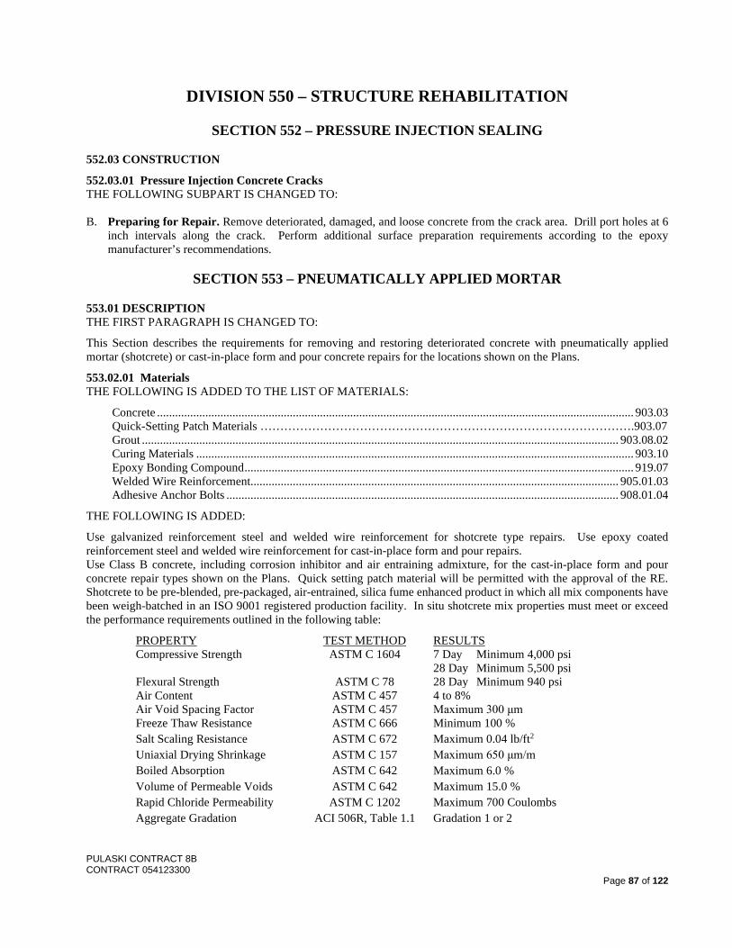
PULASKI CONTRACT 8B CONTRACT 054123300
Page 87 of 122
DIVISION 550 – STRUCTURE REHABILITATION
SECTION 552 – PRESSURE INJECTION SEALING 552.03 CONSTRUCTION
552.03.01 Pressure Injection Concrete Cracks THE FOLLOWING SUBPART IS CHANGED TO: B. Preparing for Repair. Remove deteriorated, damaged, and loose concrete from the crack area. Drill port holes at 6
inch intervals along the crack. Perform additional surface preparation requirements according to the epoxy manufacturer’s recommendations.
SECTION 553 – PNEUMATICALLY APPLIED MORTAR
553.01 DESCRIPTION THE FIRST PARAGRAPH IS CHANGED TO:
This Section describes the requirements for removing and restoring deteriorated concrete with pneumatically applied mortar (shotcrete) or cast-in-place form and pour concrete repairs for the locations shown on the Plans.
553.02.01 Materials THE FOLLOWING IS ADDED TO THE LIST OF MATERIALS:
Concrete .............................................................................................................................................................. 903.03 Quick-Setting Patch Materials ………………………………………………………………………………….903.07 Grout .............................................................................................................................................................. 903.08.02 Curing Materials ................................................................................................................................................. 903.10 Epoxy Bonding Compound ................................................................................................................................. 919.07 Welded Wire Reinforcement.......................................................................................................................... 905.01.03 Adhesive Anchor Bolts .................................................................................................................................. 908.01.04
THE FOLLOWING IS ADDED:
Use galvanized reinforcement steel and welded wire reinforcement for shotcrete type repairs. Use epoxy coated reinforcement steel and welded wire reinforcement for cast-in-place form and pour repairs. Use Class B concrete, including corrosion inhibitor and air entraining admixture, for the cast-in-place form and pour concrete repair types shown on the Plans. Quick setting patch material will be permitted with the approval of the RE. Shotcrete to be pre-blended, pre-packaged, air-entrained, silica fume enhanced product in which all mix components have been weigh-batched in an ISO 9001 registered production facility. In situ shotcrete mix properties must meet or exceed the performance requirements outlined in the following table:
PROPERTY TEST METHOD RESULTS Compressive Strength ASTM C 1604 7 Day Minimum 4,000 psi 28 Day Minimum 5,500 psi Flexural Strength ASTM C 78 28 Day Minimum 940 psi Air Content ASTM C 457 4 to 8% Air Void Spacing Factor ASTM C 457 Maximum 300 μm Freeze Thaw Resistance ASTM C 666 Minimum 100 % Salt Scaling Resistance ASTM C 672 Maximum 0.04 lb/ft2 Uniaxial Drying Shrinkage ASTM C 157 Maximum 650 μm/m Boiled Absorption ASTM C 642 Maximum 6.0 % Volume of Permeable Voids ASTM C 642 Maximum 15.0 % Rapid Chloride Permeability ASTM C 1202 Maximum 700 Coulombs Aggregate Gradation ACI 506R, Table 1.1 Gradation 1 or 2
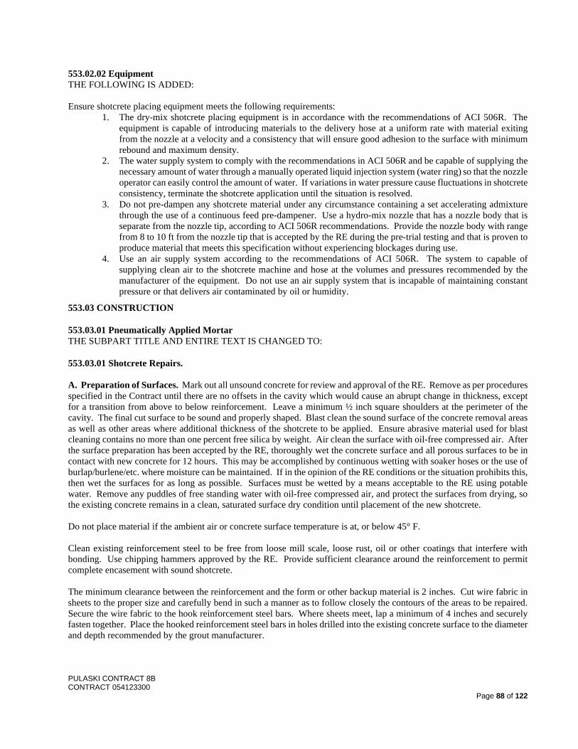
PULASKI CONTRACT 8B CONTRACT 054123300
Page 88 of 122
553.02.02 Equipment THE FOLLOWING IS ADDED: Ensure shotcrete placing equipment meets the following requirements:
1. The dry-mix shotcrete placing equipment is in accordance with the recommendations of ACI 506R. The equipment is capable of introducing materials to the delivery hose at a uniform rate with material exiting from the nozzle at a velocity and a consistency that will ensure good adhesion to the surface with minimum rebound and maximum density.
2. The water supply system to comply with the recommendations in ACI 506R and be capable of supplying the necessary amount of water through a manually operated liquid injection system (water ring) so that the nozzle operator can easily control the amount of water. If variations in water pressure cause fluctuations in shotcrete consistency, terminate the shotcrete application until the situation is resolved.
3. Do not pre-dampen any shotcrete material under any circumstance containing a set accelerating admixture through the use of a continuous feed pre-dampener. Use a hydro-mix nozzle that has a nozzle body that is separate from the nozzle tip, according to ACI 506R recommendations. Provide the nozzle body with range from 8 to 10 ft from the nozzle tip that is accepted by the RE during the pre-trial testing and that is proven to produce material that meets this specification without experiencing blockages during use.
4. Use an air supply system according to the recommendations of ACI 506R. The system to capable of supplying clean air to the shotcrete machine and hose at the volumes and pressures recommended by the manufacturer of the equipment. Do not use an air supply system that is incapable of maintaining constant pressure or that delivers air contaminated by oil or humidity.
553.03 CONSTRUCTION
553.03.01 Pneumatically Applied Mortar THE SUBPART TITLE AND ENTIRE TEXT IS CHANGED TO:
553.03.01 Shotcrete Repairs. A. Preparation of Surfaces. Mark out all unsound concrete for review and approval of the RE. Remove as per procedures specified in the Contract until there are no offsets in the cavity which would cause an abrupt change in thickness, except for a transition from above to below reinforcement. Leave a minimum ½ inch square shoulders at the perimeter of the cavity. The final cut surface to be sound and properly shaped. Blast clean the sound surface of the concrete removal areas as well as other areas where additional thickness of the shotcrete to be applied. Ensure abrasive material used for blast cleaning contains no more than one percent free silica by weight. Air clean the surface with oil-free compressed air. After the surface preparation has been accepted by the RE, thoroughly wet the concrete surface and all porous surfaces to be in contact with new concrete for 12 hours. This may be accomplished by continuous wetting with soaker hoses or the use of burlap/burlene/etc. where moisture can be maintained. If in the opinion of the RE conditions or the situation prohibits this, then wet the surfaces for as long as possible. Surfaces must be wetted by a means acceptable to the RE using potable water. Remove any puddles of free standing water with oil-free compressed air, and protect the surfaces from drying, so the existing concrete remains in a clean, saturated surface dry condition until placement of the new shotcrete. Do not place material if the ambient air or concrete surface temperature is at, or below 45° F. Clean existing reinforcement steel to be free from loose mill scale, loose rust, oil or other coatings that interfere with bonding. Use chipping hammers approved by the RE. Provide sufficient clearance around the reinforcement to permit complete encasement with sound shotcrete. The minimum clearance between the reinforcement and the form or other backup material is 2 inches. Cut wire fabric in sheets to the proper size and carefully bend in such a manner as to follow closely the contours of the areas to be repaired. Secure the wire fabric to the hook reinforcement steel bars. Where sheets meet, lap a minimum of 4 inches and securely fasten together. Place the hooked reinforcement steel bars in holes drilled into the existing concrete surface to the diameter and depth recommended by the grout manufacturer.
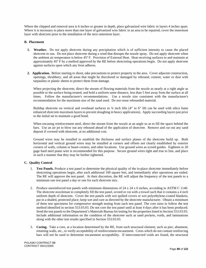
PULASKI CONTRACT 8B CONTRACT 054123300
Page 89 of 122
Where the chipped and removal area is 6 inches or greater in depth, place galvanized wire fabric in layers 4 inches apart. Where it is necessary to place more than one layer of galvanized wire fabric in an area to be repaired, cover the innermost layer with shotcrete prior to the installation of the next outermost layer. B. Placement
1. Weather. Do not apply shotcrete during any precipitation which is of sufficient intensity to cause the placed shotcrete to run. Do not place shotcrete during a wind that disrupts the nozzle spray. Do not apply shotcrete when the ambient air temperature is below 45º F. Provision of External Heat. Heat receiving surfaces to and maintain at approximately 45º F by a method approved by the RE before shotcreting operations begin. Do not apply shotcrete against surfaces upon which any frost adheres.
2. Application. Before starting to shoot, take precautions to protect property in the area. Cover adjacent construction,
openings, shrubbery, and all areas that might be discolored or damaged by rebound, cement, water or dust with tarpaulins or plastic sheets to protect them from damage.
When projecting the shotcrete, direct the stream of flowing materials from the nozzle as nearly at a right angle as possible to the surface being treated, and hold a uniform same distance, less than 5 feet away from the surface at all times. Follow the manufacturer's recommendations. Use a nozzle size consistent with the manufacturer's recommendation for the maximum size of the sand used. Do not reuse rebounded material.
Buildup shotcrete on vertical and overhead surfaces in ¾ inch lifts (4” to 6” lift can be used with silica fume enhanced shotcrete maximum layers to prevent sloughing in heavy applications). Apply succeeding layers just prior to the initial set to maintain a good bond.
When encasing reinforcement steel, direct the stream from the nozzle at an angle so as to fill the space behind the bars. Use an air jet to blow out any rebound ahead of the application of shotcrete. Remove and cut out any sand deposit if covered with shotcrete, at no additional cost.
Ground wires may be installed to establish the thickness and surface planes of the shotcrete build up. Both horizontal and vertical ground wires may be installed at corners and offsets not clearly established by exterior corners of walls, column or beam corners, and other locations. Use ground wires as screed guides. Eighteen or 20 gage hard steel piano wire is recommended for this purpose. Secure ground wires tight and true to line, and place in such a manner that they may be further tightened.
C. Quality Control
1. Test Panels. Produce a test panel to determine the physical quality of the in-place shotcrete immediately before shotcreting operations begin, after each additional 100 square feet, and immediately after operations are ended. The RE will approve the test panel. At their discretion, the RE will adjust the frequency of the test panels to a minimum one test panel a day or one for each shotcrete mix.
2. Produce unreinforced test panels with minimum dimensions of 24 x 24 x 6 inches, according to ASTM C 1140.
The shotcrete nozzleman to completely fill the test panel, screed or cut with a trowel such that it contains a 4 inch uniform depth of shotcrete. Cover the test panels with wet quilted covers or wet polyethylene-coated blankets; put in a shaded, protected place; keep wet and cure as directed by the shotcrete manufacturer. Obtain a minimum of three test specimens for compressive strength testing from each test panel. The core sizes to follow the test method identified in section 553.03.03. Do not core the test panel until at least 4 days after it has been produced. Send the test panels to the Department’s Materials Bureau for testing for the properties listed in Section 553.03.03. Include additional information on the condition of the shotcrete such as sand pockets, voids, and laminations along with the other test results specified in Section 553.03.03.
3. Coring. Take a core, at a location determined by the RE, from each structural element, such as pier, abutment,
retaining walls, etc., to verify acceptability of reinforcement encasement. Cores which do not contain reinforcing bars will not be used to determine encasement acceptability. If interconnected voids are found, the structural
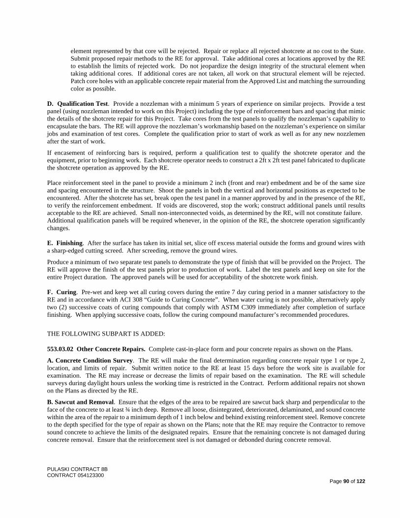
PULASKI CONTRACT 8B CONTRACT 054123300
Page 90 of 122
element represented by that core will be rejected. Repair or replace all rejected shotcrete at no cost to the State. Submit proposed repair methods to the RE for approval. Take additional cores at locations approved by the RE to establish the limits of rejected work. Do not jeopardize the design integrity of the structural element when taking additional cores. If additional cores are not taken, all work on that structural element will be rejected. Patch core holes with an applicable concrete repair material from the Approved List and matching the surrounding color as possible.
D. Qualification Test. Provide a nozzleman with a minimum 5 years of experience on similar projects. Provide a test panel (using nozzleman intended to work on this Project) including the type of reinforcement bars and spacing that mimic the details of the shotcrete repair for this Project. Take cores from the test panels to qualify the nozzleman’s capability to encapsulate the bars. The RE will approve the nozzleman’s workmanship based on the nozzleman’s experience on similar jobs and examination of test cores. Complete the qualification prior to start of work as well as for any new nozzlemen after the start of work.
If encasement of reinforcing bars is required, perform a qualification test to qualify the shotcrete operator and the equipment, prior to beginning work. Each shotcrete operator needs to construct a 2ft x 2ft test panel fabricated to duplicate the shotcrete operation as approved by the RE. Place reinforcement steel in the panel to provide a minimum 2 inch (front and rear) embedment and be of the same size and spacing encountered in the structure. Shoot the panels in both the vertical and horizontal positions as expected to be encountered. After the shotcrete has set, break open the test panel in a manner approved by and in the presence of the RE, to verify the reinforcement embedment. If voids are discovered, stop the work; construct additional panels until results acceptable to the RE are achieved. Small non-interconnected voids, as determined by the RE, will not constitute failure. Additional qualification panels will be required whenever, in the opinion of the RE, the shotcrete operation significantly changes. E. Finishing. After the surface has taken its initial set, slice off excess material outside the forms and ground wires with a sharp-edged cutting screed. After screeding, remove the ground wires.
Produce a minimum of two separate test panels to demonstrate the type of finish that will be provided on the Project. The RE will approve the finish of the test panels prior to production of work. Label the test panels and keep on site for the entire Project duration. The approved panels will be used for acceptability of the shotcrete work finish. F. Curing. Pre-wet and keep wet all curing covers during the entire 7 day curing period in a manner satisfactory to the RE and in accordance with ACI 308 “Guide to Curing Concrete”. When water curing is not possible, alternatively apply two (2) successive coats of curing compounds that comply with ASTM C309 immediately after completion of surface finishing. When applying successive coats, follow the curing compound manufacturer’s recommended procedures.
THE FOLLOWING SUBPART IS ADDED:
553.03.02 Other Concrete Repairs. Complete cast-in-place form and pour concrete repairs as shown on the Plans.
A. Concrete Condition Survey. The RE will make the final determination regarding concrete repair type 1 or type 2, location, and limits of repair. Submit written notice to the RE at least 15 days before the work site is available for examination. The RE may increase or decrease the limits of repair based on the examination. The RE will schedule surveys during daylight hours unless the working time is restricted in the Contract. Perform additional repairs not shown on the Plans as directed by the RE.
B. Sawcut and Removal. Ensure that the edges of the area to be repaired are sawcut back sharp and perpendicular to the face of the concrete to at least ¾ inch deep. Remove all loose, disintegrated, deteriorated, delaminated, and sound concrete within the area of the repair to a minimum depth of 1 inch below and behind existing reinforcement steel. Remove concrete to the depth specified for the type of repair as shown on the Plans; note that the RE may require the Contractor to remove sound concrete to achieve the limits of the designated repairs. Ensure that the remaining concrete is not damaged during concrete removal. Ensure that the reinforcement steel is not damaged or debonded during concrete removal.
PULASKI CONTRACT 8B CONTRACT 054123300
Page 91 of 122
The Contractor may remove concrete or prepare and shape repair areas with power chipping or hand tools. Do not use pneumatic hammers heavier than nominal 30 pound class (33 pounds maximum) to remove the concrete. The Contractor may start such tools in the perpendicular position but must immediately tilt to a 45 degree operational angle. Do not operate pneumatic hammers and chipping tools at an angle exceeding 45 degrees relative to the surface of the concrete. For abutment, pier seat, or column repairs, do not extend removal under the bearing seats without approval of the RE.
Provide adequate shielding to prevent concrete or other debris from falling as specified in 201.03.09.
C. Surface Preparation. Clean concrete surfaces to be repaired and apply epoxy bonding compound.
D. Cleaning, Coating, and Splicing Reinforcement Steel. Clean corroded and uncoated reinforcement steel by sandblasting, waterblasting, or wire brushing. For coated steel, clean areas where the coating is damaged by wire brushing. Coat all existing exposed uncoated and damaged coated reinforcement steel with epoxy coating according to AASHTO M 317.
For reinforcement steel that has lost 25 percent or more of its original cross sectional area, splice new reinforcement steel of the same size. Lap the reinforcement steel at least 15 bar diameters from each end of the damaged area and wire tie together. Where reinforcement steel is broken or missing, lap new bars at least 30 bar diameters from each end of the break, and wire tie together. If necessary, perform additional chipping of adjacent concrete to provide for the lap splice.
If no reinforcement is found in the concrete repair area, provide #16 @ 12” each way.
E. Placement. Place reinforcement steel as specified in 504.03.01. Place concrete as specified in 504.03.02. Match all existing architectural features. Drill and grout reinforcement as shown on the Plans.
Ensure that the surface of the repair area is even with the adjacent existing surface. Chamfer edges to match existing.
553.04 MEASUREMENT AND PAYMENT THE FOLLOWING IS ADDED: Where the concrete repair is located at a corner, the Department will measure the area of repair for payment on the face that has the largest area, and no payment will be made for the other face. The area of deeper cast in place repairs done below the limits of shotcrete applied will not be measured separately.
SECTION 554 – PAINTING EXISTING BRIDGES 554.02.01 Materials THE FOLLOWING IS ADDED TO THE LIST OF MATERIALS:
Penetrating Sealer .......................................................................................................................................... 912.01.05 Caulking ......................................................................................................................................................... 912.01.06
THE SECOND PARAGRAPH IS DELETED.
THE FOLLOWING IS ADDED:
Submit certification that primer is compatible with steel putty and epoxy binder specified in 506.
Only a three coat, organic zinc rich primer, high build epoxy intermediate coat, and urethane finish coating system (OEU) will be considered for painting of existing steel. Select a complete coating system of an organic zinc rich primer, a high build epoxy intermediate coat and a urethane finish coat from one of the approved coating systems listed on the following website: http://www.state.nj.us/transportation/eng/technology/materials In addition to the above, ensure that the selected coating system is listed on the approved NEPCOAT product list. The Department reserves the right to select any manufacturer’s OEU coating system from the approved NEPCOAT product list. Ensure that the finish coat color is Black, Federal Standard 595B, July, 1994, Color Chip No. 27038.
Ensure that all products for the selected coating system, including thinners and solvents, are from the same manufacturer and are from the Department Qualified Product List.
PULASKI CONTRACT 8B CONTRACT 054123300
Page 92 of 122
Submit technical information and samples, as described in Subsection 106.05, of the selected coating system to the ME. Submit to the RE the paint manufacturer's recommended repair procedures to correct damage such as that caused in handling and shipping, to correct deficient or excessive coating thickness, to remove zinc salts and other contaminants that would be detrimental to succeeding coats, and to prepare the surfaces of and paint rust spots.
Provide the services of a paint or a painting technical representative from the paint manufacturer at the beginning of the cleaning and painting operations and whenever else required throughout their duration.
554.02.02 Equipment THE FOLLOWING IS ADDED AFTER THE SECOND PARAGRAPH:
Equip power tools to be used for surface preparation with vacuum attachments.
554.03.01 Pollution Control System
1. Containment Plan.
THE FOLLOWING IS ADDED AFTER THE FIRST PARAGRAPH:
Use a “Level-1 Class-A Containment System”, as specified in accordance with SSPC Guide 6i (con), on this Project for all surface preparation for all structural steel components and appurtenances. Meet or exceed visible emissions for this Project as specified in Section 5.5.1.1, Level 1 Emissions. Verify compliance with all Federal, State and Local Regulations in accordance with Section 5.5.4, Method D, Ambient Air Monitoring for Toxic Metals.
For all work over traveled lanes and adjacent shoulders, roadways, driveways and shoulder areas, use only containment system designs that employ either “rapid deployment type containment trailers” or “suspended work platforms”. Simple “bridge to grade containment” systems are not permitted at these locations. Receive approval by the RE of the containment system type and design for use at each specific location prior to implementation.
Provide “suspended work platforms” that meet all of the below listed criteria:
1. Ensure that the platform has a minimum design live load of twenty (20) pounds per square foot, excluding all OSHA safety factors. If the containment platform is also to be used as a work platform, ensure that the floor of the platform is solid/rigid and that the platform does not deflect more than one sixtieth (1/60) of the span length when loaded. Do not use unstable objects to support the platform. Do not use unstable objects for the platform.
2. Ensure that the platform has a minimum vertical clearance greater than shown on the Plans, and minimum sixteen (16) feet for other locations, after installation and until it is removed, except for specific clearances
3. Specify on the Containment Plans to be submitted for approval and employ continuous vacuuming of all spent blast material accumulated on the platform during all blast cleaning operations.
4. Provide certification in writing by an independent qualified individual that the platform has been constructed in accordance with the approved Containment Plans accepted by the Department. Minor modifications are allowed to accommodate site conditions. However, ensure that the written certification also notes that these minor field modifications will not alter the overall operation or requirements of the platform. Ensure that the independent qualified individual is not an employee of the Contractor and does not have any affiliation with the individual or firm that prepares the Contractor’s Containment Plans. The credentials of the independent qualified individual who certifies the construction of the platform are subject to the approval of the RE. Do not perform any blast cleaning operations until the written certification for the platform has been reviewed and approved by the RE.
No separate payment will be made for providing the above noted containment systems, their designs and the written certifications. Include all costs in the various unit prices bid.

PULASKI CONTRACT 8B CONTRACT 054123300
Page 93 of 122
2. Waste Disposal Plan.
THE FOLLOWING IS ADDED:
The hazardous waste generator identification number (EPA ID Number) for this Project is listed below: Structure Number EPA ID Number 0917-150 (Pulaski Skyway) NJR000070789
Send the Hazardous Waste Manifests to the following address: New Jersey Department of Transportation Bureau of Project Support 951 Parkway Avenue P.O. Box 600 Trenton, NJ 08625
Dispose of the waste generated on this Contract at an approved United States Environmental Protection Agency (USEPA) lead reclaiming facility. The Department is aware of the following two (2) possible lead reclaiming facilities, which it believes are currently approved by USEPA:
1. Exide Corporation 645 Penn Street Reading, Pa. 19612 1-800-437-8495 Contact: Robert F. Jordan
2. Encycle Texas 5500 Upriver Road Corpus Christi, Tx. 78407 1-512-289-0300
Contact: Rick Gilbert
If one (1) of the above noted possible lead reclaiming facilities is selected for use, verify that the lead reclaiming facility is currently approved by USEPA for lead reclaiming. Other lead reclaiming facilities may also be used, but only if such facilities are also approved by USEPA for lead reclaiming. Contact USEPA to determine whether or not a particular lead reclaiming facility is approved by USEPA. Submit proof of USEPA approval for lead reclaiming for the selected lead reclaiming facility to the RE prior to any cleaning or blasting operations. In the event that the Contractor is unable to legally dispose of the waste generated on this Contract at a USEPA approved lead reclaiming facility, select an alternate transportation/storage/disposal (TSD) facility. Ensure that the alternate TSD facility meets all the requirements of this subsection, with the exception of the USEPA approved lead reclaiming requirements. However, in order to use the alternate TSD facility, submit sufficient documentation to the RE for approval indicating that the waste generated is unable to be disposed of at a USEPA approved lead reclaiming facility.
3. Lead Health and Safety Plan (LHASP).
THE FOURTH SENTENCE OF THE FIRST PARAGRAPH IS CHANGED TO:
Do not begin work until the RE has approved the LHASP. Do not modify or change this plan without approval of the CIH and the RE. g. Medical Surveillance Program.
THE FOLLOWING IS ADDED:
Submit documentation to the RE verifying that all blood monitoring is conducted at a New Jersey clinical laboratory approved by OSHA, and that has demonstrated proficiency in blood lead analysis. Obtain a list of all current OSHA approved clinical laboratories for the State of New Jersey from the following web site: https://www.osha.gov/SLTC/bloodlead/state_list.html
PULASKI CONTRACT 8B CONTRACT 054123300
Page 94 of 122
The following are reference documents for the Contractor’s use: 1. Additional information is also available from the home page of the following website under laws
and regulations - standards: http://www.osha.gov
2. This publication is also available from the following website: http://www.osha.gov/Publications/osha3142.pdf
3. Additional information is also available from the home page of the following website: http://www.state.nj.us/health/eoh/survweb/
4. This publication is also available from the following website: http://www.cdc.gov/niosh/docs/91-116/
554.03.02 Cleaning and Painting A. Protection of Environment, Structure, Person, and Property. THE FOLLOWING IS ADDED AFTER THE FIRST PARAGRAPH:
Adequately protect all components/materials that are not scheduled for blast cleaning and painting during those operations. Repair all blast damage to and remove all paint overspray on these components/materials to the satisfaction of the RE
THE SECOND AND THIRD PARAGRAPHS ARE CHANGED TO:
The Contractor is hereby advised that the existing steel superstructure components have an existing paint system that includes lead. Ensure that the personnel who supervise and perform the lead paint abatement work are trained in the applicable programs that concern health and safety compliance and environmental regulations regarding lead abatement. Ensure that the training is certified by the Department of Health in accordance with N.J.S.A. 26:2q.1 et seq. and N.J.A.C. 8:62-1.1 et seq. Ensure that each supervisor and worker possess an individual lead permit as issued by the Department of Health. Ensure that the Contractor is certified by the Department of Community Affairs and the Division of Codes and Standards in accordance with N.J.S.A. 52:27d-427 et seq. and N.J.A.C. 5:17-1.1 et seq. Submit a copy of the Department of Community Affairs and the Division of Codes and Standards certification to the Bureau of Construction Services, Division of Procurement (1-609-530-2103) prior to the award of this Contract. Ensure that the Contractor is also certified SSPC QP 1 and QP 2. Maintain in good standing all the above training, permits and certifications required for the duration of this Project. The applicable regulating State agencies will monitor projects for compliance with the training, permit and certification requirements through random inspections. Failure to maintain all the above training, permits and certifications for the duration of this Project could result in default of the Contract. However, the Department reserves the right to take whatever action is deemed appropriate in this situation.
B. Cleaning. THE FOLLOWING IS ADDED TO THE FOURTH PARAGRAPH:
Use hand and power tool cleaning for additional surface preparation required at connection areas and faying surfaces including for removal of pack rust.
THE FIFTH PARAGRAPH IS CHANGED TO:
Remove all debris and other products/materials accumulated on the steel surfaces prior to cleaning. Complete a thorough examination and survey of the existing surfaces to identify areas of paint failure and corrosion that will require blast cleaning outside the limits designated.
PULASKI CONTRACT 8B CONTRACT 054123300
Page 95 of 122
THE FOLLOWING IS ADDED: “Pack-rust” is defined as the steel corrosion products that form in between plates and other individual steel pieces of a built-up bridge member that is typically accessible from only one side. Clean areas of pack-rust so that the corrosion is removed from within the gap to a depth that is as wide as the gap between the individual sound steel pieces created by the pack-rust. Clean areas of pack-rust by hand or power tool cleaning, or a combination of both, in accordance with the requirements of SSPC-SP2 and SSPC-SP3, respectively. No separate payment will be made for cleaning areas of pack-rust within steel repair limits. Include all costs in the various unit prices bid. 2. Blast Cleaning.
THE FOLLOWING IS ADDED TO THE SECOND PARAGRAPH:
In order to achieve the required anchor profile (1.5 to 3.0 mils) specified herein, it is recommended to use grit sizes of G-50 or smaller. Do not exceed a maximum anchor profile of four (4.0) mils. In the event that the anchor profile exceeds 4.0 mils, re-blast the area using a smaller sized abrasive.
D. Conditions for Painting. THE ENTIRE THIRD PARAGRAPH IS CHANGED TO:
Apply coating as per the manufacturer’s recommendations for temperature and drying time. However, do not apply coating when the temperature is below 40 degrees F. Maintain the temperature through the drying time of the coating as per the manufacturer’s time table. Allow the drying time for recoating as per the manufacturer’s time table. Do not apply the subsequent coat if the previous coat is not fully dried. Prior to applying the subsequent coat, test the previous coat dryness by nail thumb and solvents wipes.
E. Paint Application.
5. Coating Thickness. b. Organic Zinc Coating System.
THE ENTIRE SECOND PARAGRAPH IS CHANGED TO: Ensure that the minimum dry film thickness (min DFT) of the paint is not less than the following: Prime coat ……………………………………………………………………4 mils Intermediate coat ………………………………………………………..…....5 mils Finish coat………………………………………………………….…………2 mils In the event that the DFT of any coat does not meet the minimum requirements, recoat to the required DFT. Provide recoat and recoat times as recommended by the paint manufacturer. If the paint manufacturer does not recommend recoat and recoat time, re-blast and paint to the required thickness. Ensure that the maximum dry film thickness (max DFT) does not exceed the max DFT recommended by the paint manufacturer. In the event that the max DFT of any coat exceeds the max DFT recommended by paint manufacturer, remove the coating and recoat to the required thickness.
Apply the prime coat immediately after inspection and acceptance of the surface preparation. Measure the DFT by 6000 F3/Elcometer 456 equipment. Calibrate the equipment against the National Institute of Standards and Technology (NIST) calibration standards. Ensure all measurements are in accordance with SSPC-PA2.
PULASKI CONTRACT 8B CONTRACT 054123300
Page 96 of 122
7. Curing. THE FOLLOWING IS ADDED:
Paint no subsequent coats within 24 hours of the application of the previous coat, unless otherwise recommended by the manufacturer and approved by the RE. Do not leave the organic primer exposed prior to application of the intermediate coat for more than 1 week maximum, unless recommended by the manufacturer and approved by the RE.
THE FOLLOWING SUBPARTS ARE ADDED:
10. Penetrating Sealer. Before applying the striping, apply a penetrating sealer to all pack-rust areas/gaps. Do not apply the striping until the penetrating sealer has set to touch. No separate payment will be made. Include all costs in the various unit prices bid.
11. Caulking. After applying the intermediate coat and before applying the finish coat, apply caulking to all
pack-rust areas/gaps to fill them completely. Do not apply the finish coat until the caulking has dried in accordance with the manufacturer’s written instructions. No separate payment will be made. Include all costs in the various unit prices bid.
PULASKI CONTRACT 8B CONTRACT 054123300
Page 97 of 122
DIVISION 600 – MISCELLANEOUS CONSTRUCTION
SECTION 601 – PIPE
601.03 CONSTRUCTION THE FOLLOWING IS ADDED: Excavate as specified in 202.03.05 and 202.03.09.
601.04 MEASUREMENT AND PAYMENT THE FOLLOWING IS ADDED:
The Department will make payment for groundwater storage, treatment and disposal as specified in 202.04.
SECTION 602 – DRAINAGE STRUCTURES
602.03 CONSTRUCTION THE FOLLOWING IS ADDED: Excavate as specified in 202.03.05 and 202.03.09.
602.04 MEASUREMENT AND PAYMENT THE FOLLOWING IS ADDED:
The Department will make payment for groundwater storage, treatment and disposal as specified in 202.04.
SECTION 603 – SLOPE AND CHANNEL PROTECTION
603.03 CONSTRUCTION THE FOLLOWING IS ADDED: Excavate as specified in 202.03.04 and 202.03.10.
603.04 MEASUREMENT AND PAYMENT THE FOLLOWING IS ADDED:
The Department will make payment for groundwater storage, treatment and disposal as specified in 202.04.
SECTION 605 – FENCE
605.01 DESCRIPTION THE FOLLOWING IS ADDED:
This Section also describes the requirements for constructing security fencing, gates and locks.
605.02 MATERIALS 605.02.01 Materials THE FOLLOWING ARE ADDED TO THE MATERIALS LIST:
Barbed Wire for Security Fence ........................................................................................................ 913.02.04 Steel Barbed Tape Concertina for Security Fence...................................................................................... 913.02.04
PULASKI CONTRACT 8B CONTRACT 054123300
Page 98 of 122
THE FOLLOWING SUBPART IS ADDED: 605.03.05 Security Fence
Construct security fencing in accordance with 605.03.01, and as shown in the Plans. Set the bottom of the fence fabric 2 inches above the ground line. The bottom of the lowest fence fabric may range between a minimum clearance of 1 ½ inches and a maximum clearance of 2 ½ inches. Grade the adjacent ground and re-establish existing ground surface as necessary to meet these requirements.
Construct fence with strands of barbed wire in accordance with the details shown in the Plans. Stretch the barbed wire to prevent sag and install in the slots of the extension arms. Stretch the barbed tape concertina to provide 16 inch concertina spacing and attach concertina tape to the barbed wire with 16 gage stainless steel tie wires.
605.04 MEASUREMENT AND PAYMENT THE FOLLOWING ITEM IS ADDED:
Item Pay Unit SECURITY FENCE LINEAR FOOT
THE FOLLOWING IS ADDED: The Department will measure and make payment for security fencing along the bottom line of the fabric.
SECTION 607 – CURB THE FOLLOWING SUBPART IS ADDED:
607.03.08 Concrete Barrier Curb with Moment Slab A. Underlayer Preparation. Prepare the underlying surface as specified in 607.03.02A.
B. Constructing Forms. Construct forms as specified in 607.03.01.B.
C. Reinforcement. Place reinforcement steel as shown on the Plans and ensure that they remain in position until the concrete is set.
D. Installing Joints. Place ½-inch preformed joint filler at transverse joint locations and ensure that it is flush with the top and faces of the curb. Place ½-inch preformed joint filler between the curb and concrete pavement, if any, and seal the joint with hot-poured joint sealer.
E. Placing Concrete. Place concrete for vertical and sloping curb as specified in 607.03.01D.
F. Finishing Concrete. Finish the top and front face of the curb as specified in 607.03.01.E.
G. Protecting and Curing Concrete. Immediately after finishing the concrete, apply curing compound as specified in 504.03.02.F.1. Protect the concrete as specified in 504.03.02.I.
H. Installing Flexible Delineators. Install flexible delineators as specified in 607.03.01.G.
607.04 MEASUREMENT AND PAYMENT THE FOLLOWING ITEM IS ADDED:
Item Pay Unit CONCRETE BARRIER CURB WITH MOMENT SLAB LINEAR FOOT
PULASKI CONTRACT 8B CONTRACT 054123300
Page 99 of 122
SECTION 609 – BEAM GUIDE RAIL
609.03.01 Beam Guide Rail THE FOLLOWING IS ADDED TO THE FOURTH PARAGRAPH:
Install additional posts and blockouts as required for stiffening near obstructions.
THE FOLLOWING IS ADDED AT THE END OF THE SUBSECTION:
Remove trees and shrubs as specified in 801.03 and 802.03 from the entire guide rail element extending 4 feet behind the guide rail post.
609.03.05 Reset Beam Guide Rail THE FOLLOWING IS ADDED AT THE END OF THE SUBSECTION:
Remove trees and shrubs as specified in 801.03 and 802.03 from the entire guide rail element extending 4 feet behind the guide rail post.
609.04 MEASUREMENT AND PAYMENT THE EIGHTH PARAGRAPH IS DELETED
SECTION 610 – TRAFFIC STRIPES, TRAFFIC MARKINGS, AND RUMBLE STRIPS
610.03.03 RPMs (Raised Pavement Markers) THE FOLLOWING IS ADDED AFTER THE LAST PARAGRAPH:
Ensure that RPMs are installed within 14 days of opening each day’s surface paving to traffic.

PULASKI CONTRACT 8B CONTRACT 054123300
Page 100 of 122
DIVISION 700 – ELECTRICAL
SECTION 701 – GENERAL ITEMS
701.03.01 Existing Systems THE FIFTH PARAGRAPH IS CHANGED TO:
If removal of existing above ground electrical material is required, deliver salvaged materials to the nearest Department electrical maintenance yard and unload the salvaged materials as directed. Dispose of salvaged materials rejected by the Department from the Project Limits as specified in 201.03.09. Deliver and unload salvaged ITS materials to:
Mobility Management North (MMN)- ITS Maintenance 670 River Drive Elmwood Park, NJ 07407-1347 Telephone: 732-697-7360
THE FOLLOWING IS ADDED:
If new cable or wire is designated to be installed into existing conduit systems, clean and swab the conduit system prior to installing the cable or wire. After cleaning, test each conduit by pulling through a metal ball with a diameter at least 85 percent of the nominal inside diameter of the conduit to ensure the conduit is free of any obstruction or foreign material. If the ball fails to pass through the conduit, repair or replace the defective conduit as directed by the RE. Restore disturbed areas to original condition.
Test the existing tracer wire in the conduit for continuity. If there is no existing tracer wire in any of the conduits in the same trench, then install a continuous tracer wire between the adjacent junction boxes without any splice when installing the cable and wire as directed by the RE.
701.03.04 Rigid Metallic Conduit (Exposed) THE FOLLOWING IS ADDED:
Ensure all exposed conduit is PVC coated. Install true tape marked in 1-foot increments for the length of the rigid metallic conduit.
701.03.15 Cable and Wire
C. Connection and Coordination with Utility Services. THE FOLLOWING IS ADDED:
Obtain and provide for utility services required for testing and operation of highway lighting systems until interim acceptance of each system or device. Utility Services may be governed by differing Authorities Having Jurisdiction (AHJ). Along with Utility Requirements, comply with all AHJ requirements. Upon successful completion of level C testing and acceptance of any device, provide the RE with a letter requesting transfer of utility services providing the latest copy of the utility bill from each utility company. Such transfers are to be effective beginning the next monthly billing cycle after completion of successful highway lighting system testing as specified in Section 704 and interim acceptance of the device or as directed by the RE.
Once new utility services have been energized or activated and the utility company has de-energized and unhooked the old service connection; remove existing pole risers and service heads, cut back one foot below grade, and plug the conduits.
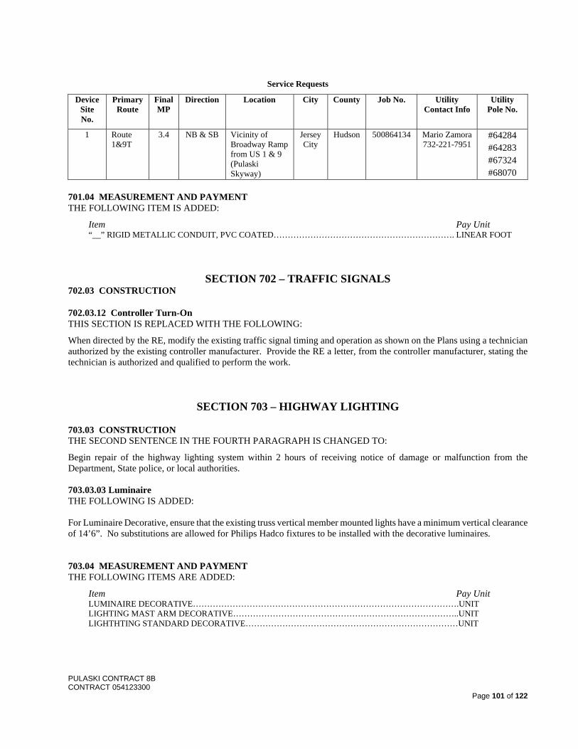
PULASKI CONTRACT 8B CONTRACT 054123300
Page 101 of 122
Service Requests
Device Site No.
Primary Route
Final MP
Direction Location City County Job No. Utility Contact Info
Utility Pole No.
1 Route 1&9T
3.4 NB & SB Vicinity of Broadway Ramp from US 1 & 9 (Pulaski Skyway)
Jersey City
Hudson 500864134 Mario Zamora 732-221-7951
#64284 #64283 #67324 #68070
701.04 MEASUREMENT AND PAYMENT THE FOLLOWING ITEM IS ADDED:
Item Pay Unit “__” RIGID METALLIC CONDUIT, PVC COATED………………………………………………………. LINEAR FOOT
SECTION 702 – TRAFFIC SIGNALS 702.03 CONSTRUCTION
702.03.12 Controller Turn-On THIS SECTION IS REPLACED WITH THE FOLLOWING:
When directed by the RE, modify the existing traffic signal timing and operation as shown on the Plans using a technician authorized by the existing controller manufacturer. Provide the RE a letter, from the controller manufacturer, stating the technician is authorized and qualified to perform the work.
SECTION 703 – HIGHWAY LIGHTING
703.03 CONSTRUCTION THE SECOND SENTENCE IN THE FOURTH PARAGRAPH IS CHANGED TO:
Begin repair of the highway lighting system within 2 hours of receiving notice of damage or malfunction from the Department, State police, or local authorities. 703.03.03 Luminaire THE FOLLOWING IS ADDED: For Luminaire Decorative, ensure that the existing truss vertical member mounted lights have a minimum vertical clearance of 14’6”. No substitutions are allowed for Philips Hadco fixtures to be installed with the decorative luminaires. 703.04 MEASUREMENT AND PAYMENT THE FOLLOWING ITEMS ARE ADDED:
Item Pay Unit LUMINAIRE DECORATIVE………………………………………………………………………………….UNIT LIGHTING MAST ARM DECORATIVE……………………………………………………………………..UNIT LIGHTHTING STANDARD DECORATIVE…………………………………………………………………UNIT
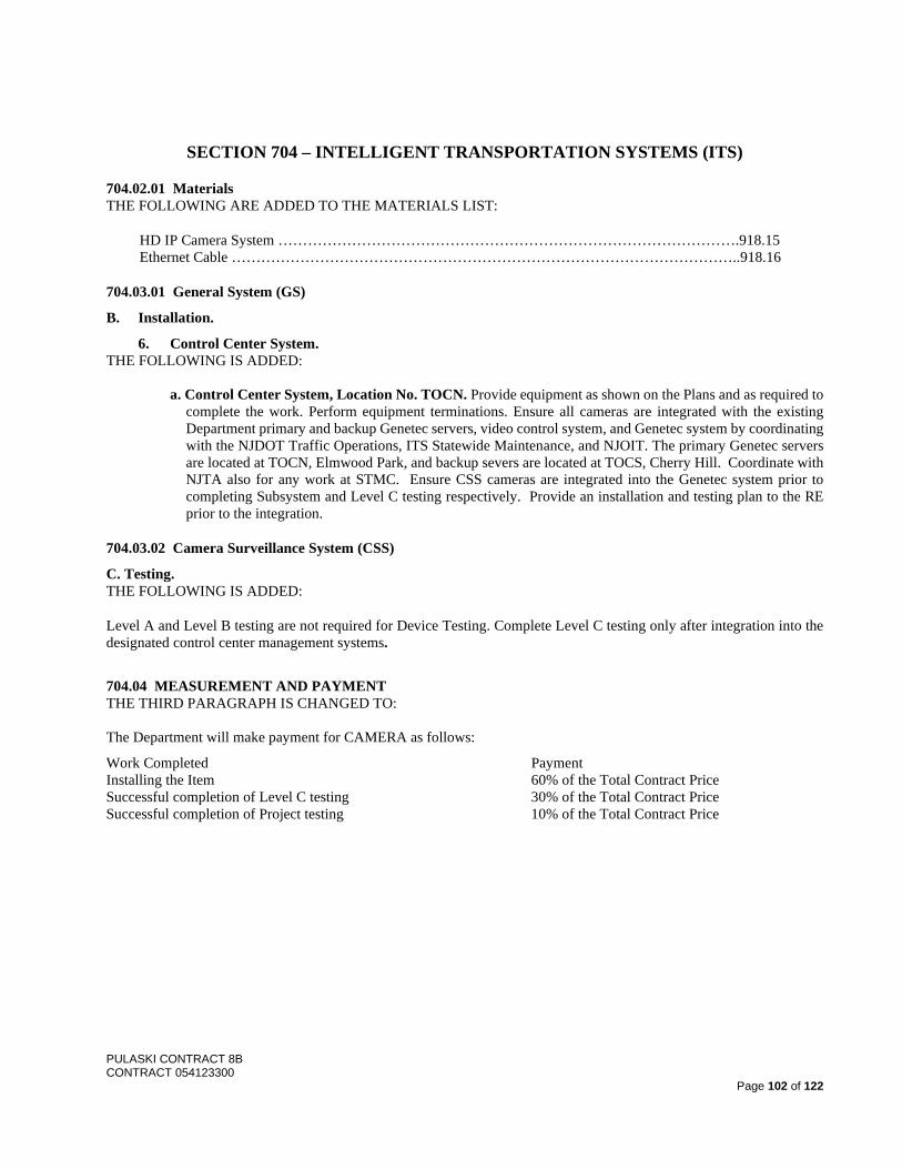
PULASKI CONTRACT 8B CONTRACT 054123300
Page 102 of 122
SECTION 704 – INTELLIGENT TRANSPORTATION SYSTEMS (ITS)
704.02.01 Materials THE FOLLOWING ARE ADDED TO THE MATERIALS LIST:
HD IP Camera System ………………………………………………………………………………….918.15 Ethernet Cable …………………………………………………………………………………………..918.16
704.03.01 General System (GS)
B. Installation.
6. Control Center System. THE FOLLOWING IS ADDED:
a. Control Center System, Location No. TOCN. Provide equipment as shown on the Plans and as required to complete the work. Perform equipment terminations. Ensure all cameras are integrated with the existing Department primary and backup Genetec servers, video control system, and Genetec system by coordinating with the NJDOT Traffic Operations, ITS Statewide Maintenance, and NJOIT. The primary Genetec servers are located at TOCN, Elmwood Park, and backup severs are located at TOCS, Cherry Hill. Coordinate with NJTA also for any work at STMC. Ensure CSS cameras are integrated into the Genetec system prior to completing Subsystem and Level C testing respectively. Provide an installation and testing plan to the RE prior to the integration.
704.03.02 Camera Surveillance System (CSS)
C. Testing. THE FOLLOWING IS ADDED:
Level A and Level B testing are not required for Device Testing. Complete Level C testing only after integration into the designated control center management systems.
704.04 MEASUREMENT AND PAYMENT THE THIRD PARAGRAPH IS CHANGED TO: The Department will make payment for CAMERA as follows:
Work Completed Payment Installing the Item 60% of the Total Contract Price Successful completion of Level C testing 30% of the Total Contract Price Successful completion of Project testing 10% of the Total Contract Price
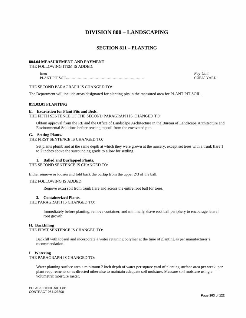
PULASKI CONTRACT 8B CONTRACT 054123300
Page 103 of 122
DIVISION 800 – LANDSCAPING
SECTION 811 – PLANTING
804.04 MEASUREMENT AND PAYMENT THE FOLLOWING ITEM IS ADDED:
Item Pay Unit PLANT PIT SOIL………………………………………………………. CUBIC YARD
THE SECOND PARAGRAPH IS CHANGED TO:
The Department will include areas designated for planting pits in the measured area for PLANT PIT SOIL. 811.03.01 PLANTING
E. Excavation for Plant Pits and Beds. THE FIFTH SENTENCE OF THE SECOND PARAGRAPH IS CHANGED TO:
Obtain approval from the RE and the Office of Landscape Architecture in the Bureau of Landscape Architecture and Environmental Solutions before reusing topsoil from the excavated pits.
G. Setting Plants. THE FIRST SENTENCE IS CHANGED TO:
Set plants plumb and at the same depth at which they were grown at the nursery, except set trees with a trunk flare 1 to 2 inches above the surrounding grade to allow for settling.
1. Balled and Burlapped Plants.
THE SECOND SENTENCE IS CHANGED TO:
Either remove or loosen and fold back the burlap from the upper 2/3 of the ball.
THE FOLLOWING IS ADDED:
Remove extra soil from trunk flare and across the entire root ball for trees.
2. Containerized Plants. THE PARAGRAPH IS CHANGED TO:
Immediately before planting, remove container, and minimally shave root ball periphery to encourage lateral root growth.
H. Backfilling THE FIRST SENTENCE IS CHANGED TO:
Backfill with topsoil and incorporate a water retaining polymer at the time of planting as per manufacturer’s recommendation.
I. Watering THE PARAGRAPH IS CHANGED TO:
Water planting surface area a minimum 2 inch depth of water per square yard of planting surface area per week, per plant requirements or as directed otherwise to maintain adequate soil moisture. Measure soil moisture using a volumetric moisture meter.

PULASKI CONTRACT 8B CONTRACT 054123300
Page 104 of 122
811.03.02 Plant Establishment and Maintenance Period THE THIRD PARAGRAPH IS CHANGED TO
The Department will re-inspect the plants bi-annually for 2 years, beginning 6 months after the start of the plant establishment period. If the Department determines that plants need to be replaced after each inspection, install plants as specified in 811.03.01 within 3 weeks of notification. If replacing outside of the optimal planting season as specified in Table 811.03.01-1, only used containerized or balled and burlapped plants that are certified as being dug dormant.
2. Maintenance Bond THE FOLLOWING IS ADDED:
Provide a bond to the Department in the amount of $5,000.
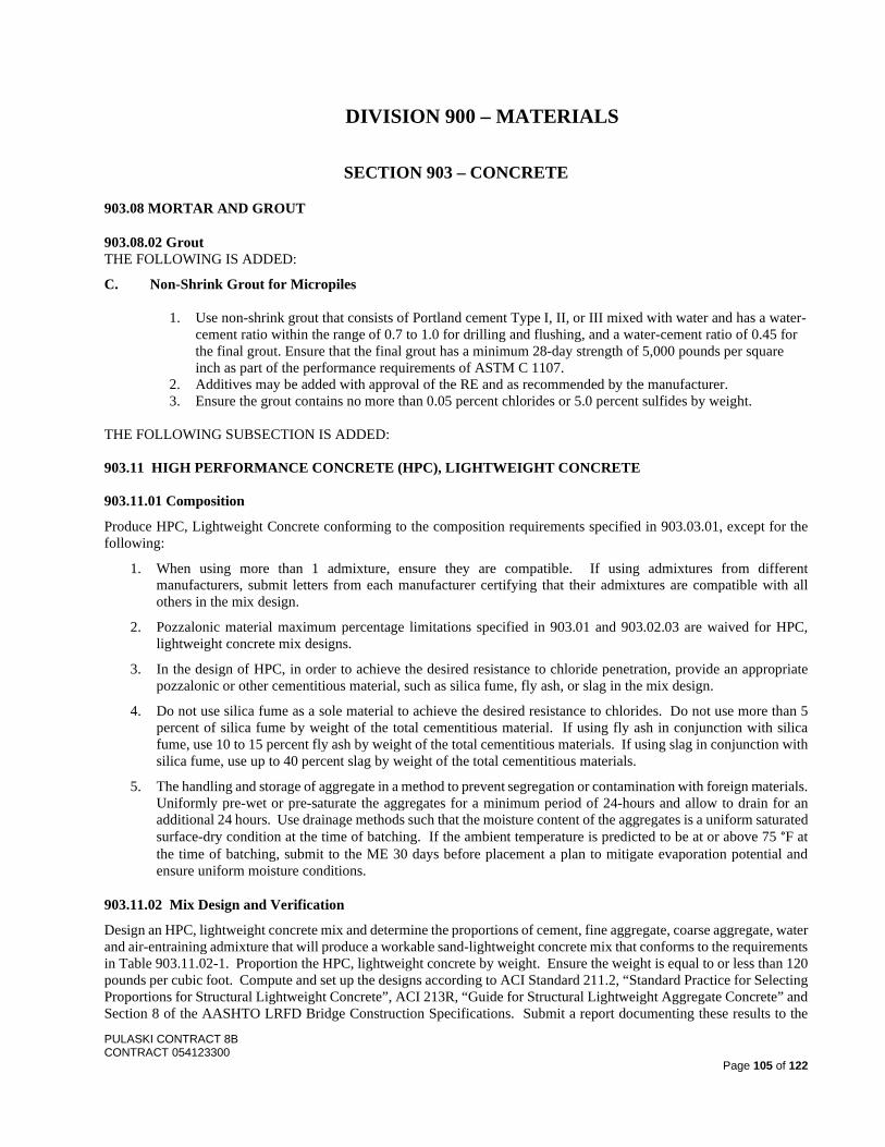
PULASKI CONTRACT 8B CONTRACT 054123300
Page 105 of 122
DIVISION 900 – MATERIALS
SECTION 903 – CONCRETE
903.08 MORTAR AND GROUT
903.08.02 Grout THE FOLLOWING IS ADDED:
C. Non-Shrink Grout for Micropiles
1. Use non-shrink grout that consists of Portland cement Type I, II, or III mixed with water and has a water-cement ratio within the range of 0.7 to 1.0 for drilling and flushing, and a water-cement ratio of 0.45 for the final grout. Ensure that the final grout has a minimum 28-day strength of 5,000 pounds per square inch as part of the performance requirements of ASTM C 1107.
2. Additives may be added with approval of the RE and as recommended by the manufacturer. 3. Ensure the grout contains no more than 0.05 percent chlorides or 5.0 percent sulfides by weight.
THE FOLLOWING SUBSECTION IS ADDED: 903.11 HIGH PERFORMANCE CONCRETE (HPC), LIGHTWEIGHT CONCRETE 903.11.01 Composition
Produce HPC, Lightweight Concrete conforming to the composition requirements specified in 903.03.01, except for the following:
1. When using more than 1 admixture, ensure they are compatible. If using admixtures from different manufacturers, submit letters from each manufacturer certifying that their admixtures are compatible with all others in the mix design.
2. Pozzalonic material maximum percentage limitations specified in 903.01 and 903.02.03 are waived for HPC, lightweight concrete mix designs.
3. In the design of HPC, in order to achieve the desired resistance to chloride penetration, provide an appropriate pozzalonic or other cementitious material, such as silica fume, fly ash, or slag in the mix design.
4. Do not use silica fume as a sole material to achieve the desired resistance to chlorides. Do not use more than 5 percent of silica fume by weight of the total cementitious material. If using fly ash in conjunction with silica fume, use 10 to 15 percent fly ash by weight of the total cementitious materials. If using slag in conjunction with silica fume, use up to 40 percent slag by weight of the total cementitious materials.
5. The handling and storage of aggregate in a method to prevent segregation or contamination with foreign materials. Uniformly pre-wet or pre-saturate the aggregates for a minimum period of 24-hours and allow to drain for an additional 24 hours. Use drainage methods such that the moisture content of the aggregates is a uniform saturated surface-dry condition at the time of batching. If the ambient temperature is predicted to be at or above 75 °F at the time of batching, submit to the ME 30 days before placement a plan to mitigate evaporation potential and ensure uniform moisture conditions.
903.11.02 Mix Design and Verification
Design an HPC, lightweight concrete mix and determine the proportions of cement, fine aggregate, coarse aggregate, water and air-entraining admixture that will produce a workable sand-lightweight concrete mix that conforms to the requirements in Table 903.11.02-1. Proportion the HPC, lightweight concrete by weight. Ensure the weight is equal to or less than 120 pounds per cubic foot. Compute and set up the designs according to ACI Standard 211.2, “Standard Practice for Selecting Proportions for Structural Lightweight Concrete”, ACI 213R, “Guide for Structural Lightweight Aggregate Concrete” and Section 8 of the AASHTO LRFD Bridge Construction Specifications. Submit a report documenting these results to the
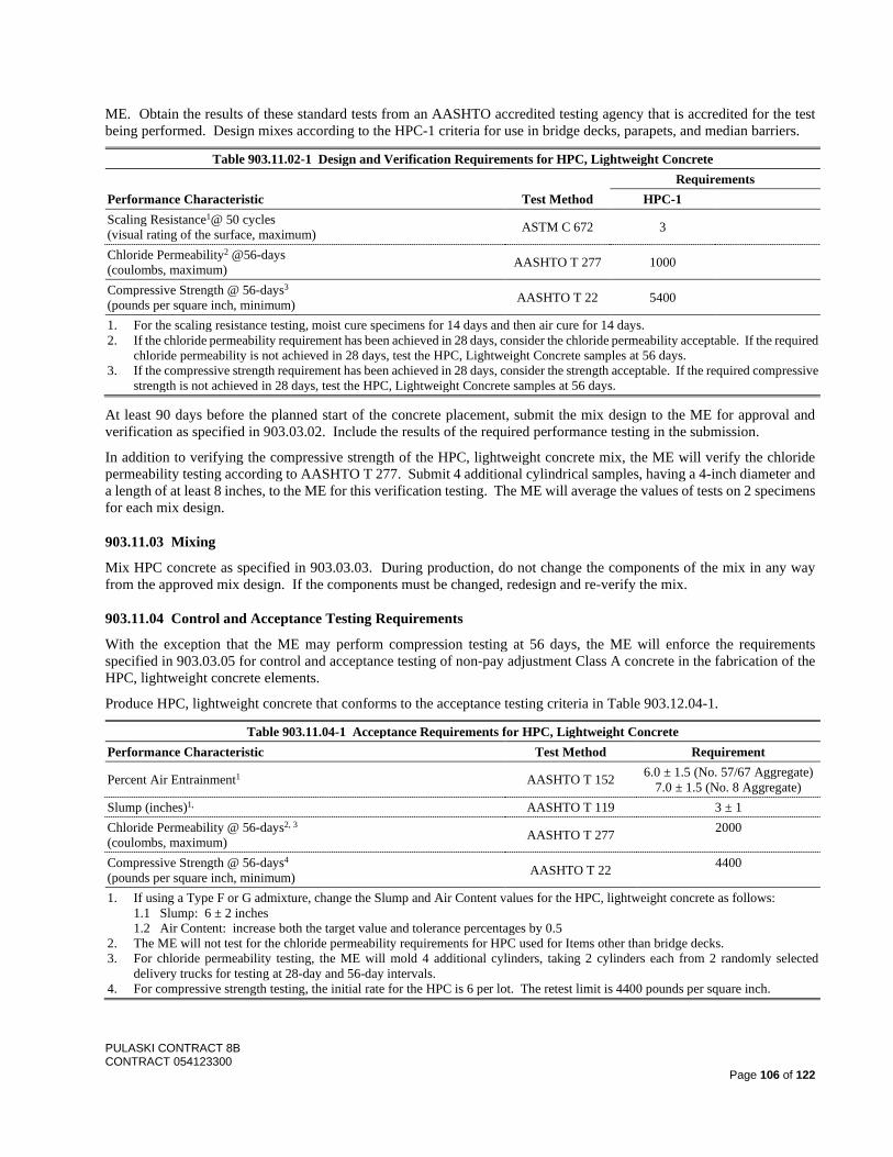
PULASKI CONTRACT 8B CONTRACT 054123300
Page 106 of 122
ME. Obtain the results of these standard tests from an AASHTO accredited testing agency that is accredited for the test being performed. Design mixes according to the HPC-1 criteria for use in bridge decks, parapets, and median barriers.
Table 903.11.02-1 Design and Verification Requirements for HPC, Lightweight Concrete
Performance Characteristic Test Method Requirements
HPC-1 Scaling Resistance1@ 50 cycles (visual rating of the surface, maximum) ASTM C 672 3
Chloride Permeability2 @56-days (coulombs, maximum) AASHTO T 277 1000
Compressive Strength @ 56-days3 (pounds per square inch, minimum) AASHTO T 22 5400
1. For the scaling resistance testing, moist cure specimens for 14 days and then air cure for 14 days. 2. If the chloride permeability requirement has been achieved in 28 days, consider the chloride permeability acceptable. If the required
chloride permeability is not achieved in 28 days, test the HPC, Lightweight Concrete samples at 56 days. 3. If the compressive strength requirement has been achieved in 28 days, consider the strength acceptable. If the required compressive
strength is not achieved in 28 days, test the HPC, Lightweight Concrete samples at 56 days.
At least 90 days before the planned start of the concrete placement, submit the mix design to the ME for approval and verification as specified in 903.03.02. Include the results of the required performance testing in the submission.
In addition to verifying the compressive strength of the HPC, lightweight concrete mix, the ME will verify the chloride permeability testing according to AASHTO T 277. Submit 4 additional cylindrical samples, having a 4-inch diameter and a length of at least 8 inches, to the ME for this verification testing. The ME will average the values of tests on 2 specimens for each mix design.
903.11.03 Mixing
Mix HPC concrete as specified in 903.03.03. During production, do not change the components of the mix in any way from the approved mix design. If the components must be changed, redesign and re-verify the mix.
903.11.04 Control and Acceptance Testing Requirements
With the exception that the ME may perform compression testing at 56 days, the ME will enforce the requirements specified in 903.03.05 for control and acceptance testing of non-pay adjustment Class A concrete in the fabrication of the HPC, lightweight concrete elements.
Produce HPC, lightweight concrete that conforms to the acceptance testing criteria in Table 903.12.04-1.
Table 903.11.04-1 Acceptance Requirements for HPC, Lightweight Concrete Performance Characteristic Test Method Requirement
Percent Air Entrainment1 AASHTO T 152 6.0 ± 1.5 (No. 57/67 Aggregate) 7.0 ± 1.5 (No. 8 Aggregate)
Slump (inches)1, AASHTO T 119 3 ± 1 Chloride Permeability @ 56-days2, 3 (coulombs, maximum) AASHTO T 277 2000
Compressive Strength @ 56-days4 (pounds per square inch, minimum) AASHTO T 22 4400
1. If using a Type F or G admixture, change the Slump and Air Content values for the HPC, lightweight concrete as follows: 1.1 Slump: 6 ± 2 inches 1.2 Air Content: increase both the target value and tolerance percentages by 0.5
2. The ME will not test for the chloride permeability requirements for HPC used for Items other than bridge decks. 3. For chloride permeability testing, the ME will mold 4 additional cylinders, taking 2 cylinders each from 2 randomly selected
delivery trucks for testing at 28-day and 56-day intervals. 4. For compressive strength testing, the initial rate for the HPC is 6 per lot. The retest limit is 4400 pounds per square inch.
PULASKI CONTRACT 8B CONTRACT 054123300
Page 107 of 122
The ME will test 2 specimens for chloride permeability and will average the results of the 2 specimens to determine the test result. The ME will perform 2 tests on each lot from samples taken from 2 randomly selected delivery trucks. The lot is eligible for 100 percent payment provided the test results are equal to or below 2000 coulombs.
Whenever 1 or more individual test results exceed 2,000 coulombs at 28 days, the ME will re-evaluate the lot at the same testing rate at 56 days. If, upon testing at 56 days, 1 or more individual test results exceed 2000 coulombs, the RE may:
1. Require that the Contractor remove and replace the defective lot, or 2. Allow the Contractor to submit a corrective action plan for approval.
SECTION 905 – REINFORCEMENT METALS
905.01.01 Reinforcement Bars THE FOLLOWING IS ADDED:
For micropile reinforcement steel, use threaded bars conforming to ASTM A722 Grade 150. Use bar couplers that develop the ultimate tensile strength of the bars without failure. 905.01.03 Welded Wire Reinforcement THE SECOND PARAGRAPH IS CHANGED TO: Galvanize the welded wire reinforcement in accordance with ASTM A 641, Class C. Wire to have a minimum yield strength of 36,000 psi. THE FOLLOWING SUBPART IS ADDED: 905.01.06 Stainless Steel Deformed Bar Reinforcement Provide deformed bar reinforcement that conforms to the requirements of ASTM A955/A955M – 12, Uniform Numbering System for Metals and Alloys (UNS) Designation S24100 (AISI TypeXM-28). The requirement for stress corresponding to a strain of 0.0035 is waived. Provide mechanical splices which develop at least 90% of the specified minimum ultimate strength of the reinforcing bars in compression and in tension. Where bars of different sizes or strengths are connected, the governing strength will be the strength of the smaller or weaker bar. Ensure the total slip of reinforcing bars within a splice sleeve does not exceed 0.040 inch, measured between gauge points clear of the splice sleeve, when the reinforcing bars are loaded in tension to 67% of the specified minimum yield strength of the reinforcing bar. Fabricate the splice sleeve and connection hardware from stainless steel alloy Type 2205, UNS designation S31803. Fabricate tie wire used to tie stainless steel reinforcement as l6gauge wire from stainless steel alloy Type 316L, UNS designation S31603, dead soft annealed, annealed at size.
SECTION 906 – STRUCTURAL STEEL
906.01 STRUCTURAL STEEL MATERIALS FOOTNOTE 1 UNDER TABLE 906.01-1 IS REPLACED WITH THE FOLLOWING:
1. Ensure steel conforms to Zone 2 impact testing requirements.
906.06 CLEANING AND PAINTING STRUCTURAL STEEL IN THE SHOP
906.06.01 Painting Materials. THE FIRST PARAGRAPH IS CHANGED TO:
Use an Organic Zinc coating system (OEU) consisting of an organic zinc-rich primer, epoxy intermediate coat, and a urethane finish coat for new structural steel. Use an Inorganic Zinc coating system (IEU) as an alternative paint system
PULASKI CONTRACT 8B CONTRACT 054123300
Page 108 of 122
for new structural steel fabricated for the Broadway Ramp superstructure steel and rocker bent replacement steel providing certification of testing results demonstrating that faying surfaces between steel surface painted with IEU and OEU systems meets Class B slip coefficient requirements is submitted and approved by RE.
THE FOLLOWING SUBSECTIONS ARE ADDED:
906.09 STEEL PUTTY
Ensure that the physical properties of epoxy steel paste conform to the following requirements:
1. Hardness (Shore D): 84±5 Durometer (Minimum) 2. Compressive Strength: 8,260 PSI (Minimum) 3. Flexural Strength: 5,300 PSI (Minimum)
Supply epoxy steel paste brands from the following manufacturers or approved equal:
1. Devcon Plastic Steel Putty (A) manufactured by: ITW Polymers Adhesives North America 30 Endicott Street Danvers, MA 01923 (855) 489-7262 www.devcon.com
2. FX-738 Metal-Filled Epoxy Paste manufactured by:
Simpson Strong-Tie Company, Inc. P.O. Box 10789 Pleasanton, CA 94588 (800) 925-5009 www.strongtie.com
3. Loctite Fixmaster Steel Putty manufactured by:
Henkel Corporation 26235 First Street Westlake, OH 44145 (800) 624-7767 www.loctiteproducts.com
906.10 STEEL CASINGS FOR MICROPILES
Use API 5CT Grade N80 steel casing of adequate thickness to withstand handling and stresses associated with advancing the casing into the ground, in addition to stresses due to hydrostatic and earth pressures. The minimum casing size, thickness and type is shown on the Plans. If a cutting shoe is used, its maximum outside diameter is not to exceed the outside diameter of the casing plus 1/4 inch. Use flush joint type casing. Do not join steel pipe sections by shop or field welding. Ensure that threaded casing joints develop at least the required nominal resistance of the micropile. Mill secondary casing may be used provided it is new and unused, in accordance with the AASHTO LRFD Bridge Construction Specifications, and complies with the “Buy America” requirements as specified in Section 106.03. New mill secondary steel pipe/casing without Mill Certification is acceptable provided it is free from defects (dents, cracks, tears) and has a minimum of two unique coupon tests per truckload (defined as 44,000 lbs).
PULASKI CONTRACT 8B CONTRACT 054123300
Page 109 of 122
SECTION 907 – BEARING ASSEMBLIES
907.01 STRUCTURAL BEARING ASSEMBLIES
907.01.02 Types
A. High-Load Multi-Rotational (HLMR) Bearing Assemblies. THE FOLLOWING IS ADDED:
For bearings mounted on piers to support the truss, use HLMR bearings designed that consist of a disc type rotational element and have a sliding surface to accommodate translation when used as an expansion or fixed bearing. Pot type or spherical type bearings are not acceptable. Fabricate HLMR bearing assemblies in accordance with Section 18 of the current AASHTO LRFD Bridge Construction Specifications.
1. Assembly Requirements. Use bearings that consist of a rotational disc, sliding surface, cushioned guide bars, shear resisting mechanism, and uplift restraints and curtains (as applicable). For the disc element, use a polyether urethane structural element confined by upper and lower steel bearing plates.
a. Shear Resisting Mechanism. Ensure that the shear resisting mechanism (SRM) can transfer all shear force from the top bearing plate to the masonry plate, and allows the bearing to rotate on the disc, and constrains the top plate to the masonry plate when uplift restraints are required as shown on the Plans
b. Sliding Surface. For the sliding surface, use confined polytetrafluoroethylene (PTFE) sliding against stainless steel. Ensure that the maximum coefficient of friction is 3 percent. Ensure that expansion and fixed bearings accommodate longitudinal and transverse displacement due to thermal expansion and contraction, wind, seismic, and other lateral loads.
c. Cushioned Guide Bars. Ensure that expansion and fixed bearings accommodate longitudinal and transverse displacement due to thermal expansion and contraction, wind, seismic, and other lateral loads. Ensure that the cushioned guide bars constrain the slide plate to accommodate the bi-directional movement shown on the Plans and that there is a gap between the guide bars and slide plate. Note that the intent of this system is to introduce flexibility and dissipate energy and, therefore, increase the damping of the superstructure. For the cushion material, use a polyether urethane pad with a Shore hardness of 45D in accordance with Section 18.3.2.8 of the AASHTO LRFD Bridge Construction Specifications. Ensure that the guidebar and cushion can resist uneven stress concentrations due to combined rotation, deflection, and lateral loads, or 2 times the tabulated lateral force shown on the Plans, whichever is greater.
d. Uplift Restraint. Provide uplift restraints where shown on the Plans. Ensure that the uplift restraint does not interfere with the bearing rotational ability.
e. Bearing Curtain. Provide an elastomeric bearing curtain on the Pier 52 bearings as shown on the Plans.
2. Testing Requirements. Conduct testing by the Manufacturer. Submit testing setup and procedures with the working drawings for approval. Submit testing results for RE approval prior to shipment. Notify the RE two weeks prior to the start of testing. The RE and Department reserves the right to be present for testing.
a. Proof Load on Full-Size Bearing. Perform short-term vertical proof load testing according to AASHTO LRFD Bridge Construction Specifications Section 18.3.4.4.4. Test one full-size bearing per lot as defined therein.
b. Proof Load on Full Size Cushion Pad. Perform short-term horizontal proof load testing on one full size cushion pad constructed to mimic the same details proposed for the production bearings according to AASHTO LRFD Bridge Construction Specifications Section 18.3.4.4.4, with the following stipulations specified here. The guidebar cushion pad may be tested as a standalone element from the full-size bearing. Measure the force and displacement and provide the compressive stiffness of the cushion pad at 25%, 50%, 75%, 100%, 125%, 150%, and 200% of the maximum design lateral load from one representative bearing.
PULASKI CONTRACT 8B CONTRACT 054123300
Page 110 of 122
Hold the load for a minimum of five minutes at each load step. Ensure that the entire pad maintains continuous and uniform contact with the testing equipment for the duration of the test. Ensure that the compressive stiffness is between 700 kip/inch and 1,500 kip/inch for the 75% to 100% compression range. If the stiffness criterion is not satisfied, adjust the pad plan area dimensions to obtain a shape factor that will meet the required stiffness range and perform the full test again. Inspect the pad after testing and ensure the pad sustains no damage at the 200% compression force to include, but not limited to, cracking or debonding of the pad. Use the test data to design and detail the production bearings.
c. Coefficient of Friction. Perform sliding coefficient of friction testing as per AASHTO LRFD Bridge Construction Specifications Section 18.3.4.4.5. Test one full-size bearing per lot as defined therein.
d. Bearing Horizontal Force Capacity. Perform horizontal force capacity testing as per AASHTO LRFD Bridge Construction Specifications Section 18.1.5.2.8, except that the horizontal load will be 2 times the maximum lateral load shown on the Plans. Test one full-size bearing per lot as defined in AASHTO LRFD Bridge Construction Specifications Section 18.3.4.
If one bearing fails one test, all the bearings of that lot will be rejected, unless the manufacturer elects to test each bearing of the lot.
3. Qualified Manufacturers. The following manufacturers have displayed the capability of manufacturing disc bearings with characteristics of the general requirements herein:
1. R. J. Watson, Inc. 11035 Walden Ave Alden, NY 14004
2. Dymat Construction Products Inc. 1339 Ocean Ave Del Mar, CA 92014
3. Cosmec Inc.
1501 Rocky Ridge Road Athens, TX 75751
4. D.S. Brown 300 East Cherry Street North Baltimore, OH 45872
Include documentation with the working drawing package showing the manufacturers previous experience designing and fabricating disc bearings. Submit documentation of a minimum of five years’ experience and ten bridge installations.
SECTION 908 – BOLTS AND BOLTING MATERIAL
908.01 STEEL BOLTING MATERIALS THE FOLLOWING IS ADDED:
Provide the following for micropile installations:
1. Ensure hex nuts develop the guaranteed ultimate strength of the solid bar for the micropile. Provide either straight or spherical.
2. Provide hex nuts that develop the guaranteed ultimate strength of the solid bar for the micropile. They can be straight or spherical.
3. Provide wedge washers and/or spherical nuts to compensate for angle changes.
PULASKI CONTRACT 8B CONTRACT 054123300
Page 111 of 122
908.02.01 Material Requirements THE FIRST PARAGRAPH IS CHANGED TO:
For structural steel erection and for steel to steel chord splices of sign structures, use high-strength steel bolts, including nuts and plain hardened washers according to ASTM F 3125, Grade A 325 or Grade A 490 unless otherwise noted. THE SECOND PARAGRAPH IS CHANGED TO:
When galvanizing is specified, use the hot-dipped method according to ASTM A 153, except for when galvanizing is specified for ASTM F 3125, Grade A 490 bolts.
When specified, provide ASTM F 3125, Grade A 490 bolts and washers that are zinc/aluminum coated as per ASTM F 1136, Grade 3 and nuts coated as per ASTM F 1136, Grade 5. Treat galvanized or coated bolts, washers, and nuts as an assembly. Store and ship the assembly in plastic bags placed inside wood or metal containers.
THE FOLLOWING IS ADDED:
For Structural Steel installation, use high-strength steel bolts, including nuts and plain hardened washers according to ASTM F3125, Grade A325X (X - threads excluded from the shear plane), unless otherwise noted. Use standard hardened washers according to ASTM A436, Type 1 under both bolt head and nut unless otherwise noted. Sampling and testing requirements for ASTM F3125, Grade A325X are the same as for ASTM A325 high-strength steel bolts.
For steel repairs and for open holes remaining in the existing structural steel after Structural Steel removal, use high-strength steel “twist off” type tension control bolts with a round head resembling a rivet head, including nuts and plain hardened washers according to ASTM F3125, Grade F1852X (X - threads excluded from the shear plane), with the hex nut facing outward where there is only access from the outside of a member for bolt installation as approved by the RE. Sampling and testing requirements are the same as for ASTM A325 high-strength steel bolts except that rotational capacity testing is not required.
Where countersunk bolts are shown on the Plans, use ASTM A307 steel bolts specified in 908.01, unless noted otherwise. Where shown on the Plans, use high-strength countersunk bolts, including nuts and washers, according to ASTM F 3125, Grade A 490X (X – threads excluded from the shear plane). Sampling and testing requirements for ASTM F 3125, Grade A490X are the same as for ASTM A490 high-strength steel bolts. Use standard hardened washers according to ASTM F436, Type 1 under an ASTM A563 DH heavy hex nut.
908.02.02 Sampling and Testing Requirements for Bolt Assemblies THE FIRST PARAGRAPH OF THE FOLLOWING SUBPART IS CHANGED TO:
B. Tensile, Proof Load, Hardness, and Coating Thickness Tests. For each lot, verify the manufacturer performs tensile, proof load, and hardness tests and measures galvanized coating according to ASTM F 3125, Grade A 325 or A 490.
THE FOLLOWING IS ADDED BEFORE THE LAST PARAGRAPH:
Conduct Magnetic Particle Inspection on 150 ksi ASTM F 3125, Grade A 490 bolts as per ASTM F 788 and ASTM E 709. Conduct Carburization/Decarburization Inspection on 150 ksi ASTM F 3125, Grade A 490 bolts as per ASTM F 2328.
SECTION 909 – DRAINAGE
909.02 PIPE 909.02.09 Fiberglass Pipe for Bridge Storm Drainage. THE SECOND PARAGRAPH IS REPLACED WITH THE FOLLOWING:
PULASKI CONTRACT 8B CONTRACT 054123300
Page 112 of 122
Ensure that all fiberglass pipe, fittings, splash guards, and adhesives use pigmented resin throughout the wall and the color is the same black color as the existing Pulaski Skyway superstructure (chip #27038) with UV stabilized resin. Painted gel-coat or exterior coating is not acceptable.
SECTION 912 – PAINTS, COATINGS, TRAFFIC STRIPES, AND TRAFFIC MARKINGS 912.01.01 Structural Steel Paint CHANGE THE FIRST AND SECOND CRITERIA UNDER THE FIRST PARAGRAPH TO:
1. Use an organic zinc, epoxy, urethane (OEU) paint system for re-coating existing structural steel and for coating new structural steel, except as noted in 2. below.
2. Use an Inorganic Zinc coating system (IEU) as an alternative paint system for new structural steel fabricated for the Broadway Ramp superstructure steel. An Inorganic Zinc coating system (IEU) may also be used as an alternative paint system for new structural steel fabricated for the rocker bent replacements.
THE FOLLOWING IS ADDED: Prior to proceeding with the alternative system, submit to the RE for approval the certification of testing results demonstrating that faying surface between steel surfaces painted with IEU and OEU systems meets Class B slip coefficient requirements. THE SECOND SENTENCE OF THE THIRD PARAGRAPH IS CHANGED TO:
The finish color for new structural steel and existing steel areas to be repaired or retrofitted to match Federal Standard 595B Color No. 27038 (Black). Submit samples of the finish coat color to the RE for approval. THE FOLLOWING SUBPARTS ARE ADDED: 912.01.05 Penetrating Sealer
Use penetrating sealer manufactured and recommended by the same manufacturer as the paint system to be used for coating structural steel. Submit MSDS, PDS and Certification of Compatibility from the paint manufacturer. 912.01.06 Caulking
Use caulking recommended by the same manufacturer as the paint system to be used for coating structural steel. Submit MSDS, PDS and Certification of Compatibility from the paint manufacturer.
SECTION 913 – GUIDE RAIL, FENCE, RAILING, AND BOX BEAM THE FOLLOWING SUBPART IS ADDED: 913.02.04 Security Fence Ensure that the barbed related materials for security fence conform to the following:
1. Barbed Wire for Security Fence. Use wires of a galvanized 3/8” 11-gauge double twist with barb spacing of 3” to 6”.
2. Steel Barbed Tape Concertina for Security Fence. Use double coil of circumferences of 24 and 30
inches. Loop spacing shall be 21 inches. Fabricate razor ribbon coils from 0,020” thick ASTM A653 (GA) galvanized steel strip. Submit blade style for approval by the RE.
Submit certifications of compliance, as specified in 106.07, for all fence materials.
PULASKI CONTRACT 8B CONTRACT 054123300
Page 113 of 122
913.03.01 Steel Railing THE FOLLOWING IS ADDED: Ensure the finish color for the steel Two-Rail Bridge Railing and the Ornamental Railing matches Federal Standard 595B Color No. 27038 (Black). Submit samples of the finish coat color to the RE for approval.
SECTION 917 – LANDSCAPING MATERIALS 917.09.04 Water Retaining Polymer THE ENTIRE TEXT IS CHANGED TO: Provide a water retaining polymer made with potassiumpropenoate-propenamide copolymer hydrogel from the following manufacturers or approved equal:
1. Gelscape, Amereq Corporation, 50 North Harrison, Congers, NY 10920. 2. Soilmoist, JRM Chemical Inc., 13600 Broadway Avenue, Clevelend, OH 44125 3. Supersorb, Aqueatrols Corporation, 5 North Olney Avenue, Cherry Hill, NJ 08003
SECTION 918 – ELECTRICAL MATERIALS
918.01 CONDUIT AND FITTINGS THE FOLLOWING IS ADDED:
5. Rigid Metallic Conduit, PVC Coated. Ensure the conduit conforms to Federal Spec. WWC-581E, ANSI Spec. C80.1 and UL 6 prior to coating, and is hot dipped galvanized inside and out throughout its entire length including the threads. Coat the interior of the conduit with a blue urethane coating of a nominal thickness of .002" (2 mils). Coat the exterior of the conduit with a black PVC coating of a minimum thickness of .040" (40 mils) applied by dipping in liquid plastisol. Ensure exterior of the conduit is black in color. Ensure all coated conduit conforms to NEMA Standard no. RN-1. Verify the conduit is bendable without damage to either interior or exterior coating. Apply a .002" (2 mils) nominal thickness coating of blue urethane to the exterior, the interior and the threads of all fittings and coupling. Apply a .040" (40 mils) minimum thickness of coating of PVC to the exterior of all fittings. Ensure all hub fittings and couplings have a PVC sleeve extending one pipe diameter or 2" whichever is less. Ensure the ID of the sleeve is equal to the OD of the uncoated pipe. Verify the bond between the coating and the metal is greater than the tensile strength of the coatings. Provide a loose coupling with each length of conduit and the coupling with longitudinal ribs to enhance installation. Utilize special tools as recommended by the coated conduit manufacturer during installation.
918.08 CAST BOXES AND FITTINGS THE FOLLOWING IS ADDED: Ensure Stainless Steel Junction Box is rated for use in outdoor corrosive environments and provides water-tight seal. Ensure the following is met: Standards
− UL 508A Listed − NEMA Type 4X, 12, 13 − IEC 60529, IP66
PULASKI CONTRACT 8B CONTRACT 054123300
Page 114 of 122
Material − 14 gauge, Type 304 Stainless Steel body and door − Unpainted brushed finish
Other Characteristics − Continuously welded smooth seams. − Single door, and seamless foam-in-place gasket or neoprene gasket attached to door with oil resistant
adhesive. − Rolled lip around three sides of door. − Stainless Steel door clamp assembly. − Hasp and staple for padlocking. − Door removal by pulling stainless steel continuous hinge pin. − Bonding and grounding provisions.
918.14 LAMPS
2. Highway Lighting. THE ENTIRE TEXT IS CHANGED TO:
Use light emitting diode (LED) lamps that have electrical, physical, and photometric characteristics that conform to ANSI Standards. Ensure that the lamps are rated for 65,000 hours of average life at 25 degrees C.
Ensure the luminaires are manufactured by Philips Hadco and are model LEDGINE LED Teardrop (TXF9) with the flat brim. No exceptions permitted. Ensure the following characteristics are provided:
Wattage = 35W Lumens = 3578 Voltage = 277V LED’s = 32 Finish = Black Color Temperature = 4000K
THE FOLLOWING SUBSECTIONS ARE ADDED:
918.15 HD IP CAMERA SYSTEM
Ensure High Definition IP Camera System is compatible with existing architecture and conforms to the following specifications: A. General
1. General Specifications a. Ensure that the camera:
(1) Is a dome or positional type as specified in the Contract. (2) Is compatible with encoder integral to IP camera. (3) Is High Definition (HD) with superior 1080P image quality (4) Has Electronic Image Stabilization (5) Has Compass Direction and scene presets
2. Standards a. NEMA Type 4X b. As a minimum, IP 66 Environmental Rating c. ONVIF Profile S d. UL Listed for outdoor use e. NEC
3. Power Supply
PULASKI CONTRACT 8B CONTRACT 054123300
Page 115 of 122
a. Power: 24 VAC or PoE with 70W Power Injector b. Input voltage: 120 volt user selectable. c. UL listed and meeting NEMA 4X and IP66 standards.
4. Power and Communications Cables a. Ensure that the unit is provided with all power, control, and communications cables. Ensure
they are suitable for burial underground in a duct and able to withstand wet environments. b. Ensure power cables provide power to Camera & network equipment, including ancillary
equipment to provide proper functionality and for testing purposes. Ensure cables are of proper length as shown in the Plans.
5. Head End Compatibility a. Ensure the provided equipment is compatible from the camera to the head end Genetec
controller software and meets applicable NTCIP requirements. b. This requirement is solely determined by the Contractor’ System Integrator based on the
proposed system submitted for approval. c. Input voltage for the power supplies are to be 120 Volt, 60 Hz and output voltage meeting
code translation requirements. d. Ensure that the units are UL listed and meet NEMA 1 standards.
6. Network a. Protocols-IPv4, IPv6, HTTP, HTTPS, FTP, SMNP, RTP, RTSP b. Security Access-Password Protected,2-Level Security c. Software Interface-Web Browser View and Setup d. Video has Intelligent Analytics
B. Network Interface Box
1. Ensure that the network monitoring system includes the necessary kits, ports and cables designed to provide ground level, local interface to the field installed system. Ensure conformity to NEMA 4X, UL, and FCC Class B Ratings where they apply. Surface mounted RJ-45 connection box will be installed in cabinet before connection to equipment. a. The outdoor CCTV network port allows for the control and setup of camera when in
the lowered position. Install weather resistant RJ-45 coupler in camera housing b. The remote data port allows for new operating code and language files to be uploaded to
camera system. c. The remote data port is able to receive commands from standard personal computers utilizing
IP communications between the remote data port and camera system. d. The enclosure and data port meets or exceeds the following design and performance
specifications: 1) At least one RJ-45 for control, programming, and viewing 2) Video transmission from camera system to control equipment over Ethernet 3) Lock out control from head end when cable is plugged into RJ-45 jack 4) Weather resistant connector 5) Each network data port controls only one camera system
C. Dome IP Camera System 1. Ensure that the Dome Camera is an outdoor environmental CCTV camera dome system with a discreet,
miniature camera dome system consisting of a dome drive with a variable speed/high speed pan and tilt drive unit with continuous 360° rotation, 30 x optical zoom lens with 12 x digital zoom and auto focus; and an enclosure consisting of a back box, lower dome, and a quick-install pole adapted mounting. Ensure that the unit meets NEMA Type 4X and IP66 environmental standards and is suitable for outdoor installation atop poles up to 100’ high. Ensure that the unit operates at 24 VAC nominal with maximum 110 Watt power consumption.
2. Ensure that the unit meets or exceeds the following design and performance specifications: a. Dome Drive
(1) Pan Range: 360° continuous rotation, 45° per second (2) Tilt Range: Unobstructed tilt of +2° to -92° (3) Manual Control Speed: Pan speed of 0.1° to 80° per second (4) PTZ Protocol: ONVIF Profile S compliant
PULASKI CONTRACT 8B CONTRACT 054123300
Page 116 of 122
(5) Automatic Preset Speed: Pan speed of 250° and a tilt speed of 100° per second (6) Presets: Sixty-four preset positions with a 20-character label available for each position;
programmable camera settings, including selectable auto focus modes, iris level, and backlight compensation, for each preset; command to copy camera settings from one preset to another; preset programming through control keyboard or through dome system on-screen menu
(7) Preset Accuracy: 0.1° (8) Proportional Pan/Tilt Speed: Speed decreases in proportion to the increasing depth of zoom (9) Automatic Power-Up: User-selectable to the mode of operation the dome will assume when
power is cycled, including automatically returning to position or function occurring before power outage
(10) Zones: Eight zones with up to 20-character labeling for each, with ability to blank the video in the zone
(11) Motor Operating Mode: Micro step to 0.015° steps (12) Motor: Continuous duty, variable speed, operating at 18 to 30 VAC, 24 VAC nominal (13) Limit Stops: Programmable for manual panning, auto/random scanning, and frame
scanning (14) Alarm Inputs: N.O./N.C. dry contacts (15) Alarm Outputs: One auxiliary Form C relay output and one open collector auxiliary output (16) Alarm Output Programming: Auxiliary outputs can be alternately programmed to operate
on alarm (17) Alarm Action: Individually programmed for three priority levels, initiating a stored pattern
or going to a pre-assigned preset position. (18) Resume after Alarm: After completion of alarm, dome returns to previous programmed
state or its previous position (19) Window Blanking: Eight four-sided, user-defined shapes, with each side being of different
lengths; window blanking setting to turn off at user-defined zoom ratio; window blanking set to opaque gray or translucent smear; blank all video above user- defined tilt angle; blank all video below user-defined tilt angle
(20) Patterns: Four user-defined programmable patterns including pan, tilt, zoom, and preset functions; pattern programming through control keyboard or through dome system onscreen menu
(21) Pattern Length: Four patterns of user-defined length, based on dome memory (22) Auto Sensing: Automatically sense and respond to protocol utilized for controlling unit;
including NTCIP compliant control protocols and translators (23) Menu System: Built-in for setup of programmable functions in English (24) Auto Flip: Rotates dome 180° at bottom of tilt travel (25) Password Protection: Programmable settings with optional password protection (26) Clear: Clear individual, grouped, or all programmed settings (27) Diagnostics: On-screen diagnostic system information (28) Freeze Frame: Freeze current scene of video during preset movement (29) Display Setup: User-definable locations of all labels and displays; user selectable time
duration of each display (30) Azimuth/Elevation/Zoom: On-screen display of pan and tilt locations and zoom ratio (31) Compass Display: On-screen display of compass heading; user- definable compass setup (32) Video Output Level: User-selectable: normal or high to compensate for long video wire
runs (33) Dome Drive Compatibility: All dome drives are compatible with all back box
configurations (34) RJ-45 Jack: Plug-in jack on dome drive for control and setup of unit and for uploading new
operating code and language file updates. Compatible with personal computers. (35) Network Interface Compatibility: Ability to control and setup unit and to upload new
operating code and language file updates through optional network interface port that is located in area of cabinet with easy access. Compatible with personal computers.
PULASKI CONTRACT 8B CONTRACT 054123300
Page 117 of 122
(36) UTP Compatibility: Ability to plug into back box an optional board that converts video output to passive, unshielded twisted pair transmission
(37) Fiber Optic Compatibility: Ability to plug into back box an optional third-party board that converts video output and control input to fiber optic transmission
(38) Third-Party Control Systems: Ability to plug in optional board that converts control signals from selected third-party controllers
(39) Power Consumption: Maximum 110 W (40) Operating Temperature: -29° F to 122° F and capable of De-icing and operating at an
ambient temperature of -13° F. within two hours of power on. b. Back Box and Lower Dome
(1) Heavy Duty Pendant Environmental capable of mounting to standard lowering device. (2) Connection to Dome Drive: Quick, positive mechanical and electrical disconnect without
the use of any tools (3) Trap Door: Easy-access trap door that allows complete access to the installation wiring and,
when closed, provides compete separation of the wiring from the dome drive mechanics (4) Terminal strips: Removable with screw-type terminals for use with a wide range of wire
gauge sizes (5) Auxiliary Connections: One Form-C relay output at <40 V, 2 A maximum, and a second
open collector output at 32 VDC maximum at 30 mA (6) Alarm inputs: Four (7) Installation: Quick-mount wall, corner, pole, parapet, or ceiling adapter (8) Cable Entry: Through a 1.5-inch NPT fitting (9) Environmental Features: Factory-installed heaters, blowers, and sun shroud (10) Operating Temperatures: Continuous operating range of -29.2° to 122°F (11) Memory: Built-in memory storage of camera and location- specific dome settings such
as presets and patterns. If new drive is installed in back box, all settings to download automatically into new dome drive
(12) Color: Gray, baked-on enamel powder coat with dome optically clear, impact and scratch resistant coating.
(13) Construction: Anti-impact, vandal resistant, dual wall aluminum enclosure with a min, 0.090-inch thick, clear polycarbonate lower dome and aluminum trim ring
(14) Disconnect: Quick to dome drive (15) Dimensions: Pendant 10.6-13.74-inch overall length (including dome) by 8.6-
11.05-inch diameter (16) Weight: 14.0 lbs. max
c. IP Camera Specifications (1) Technical Specifications
a) Digital Format 1080p, 1080i, 720p b) Scanning System Progressive c) Image Sensor 1/1.8, 1/2.8 inch CMOS d) Camera Format Day/Night (IR Cut Filter) e) Resolution 1,920 x 1,080 f) Aperature f/1.4 ->f4.6 g) Zoom Lens 30 X optical, 12X Digital h) Zoom Speed Optical Range Minimum 2 settings: i) (Focus Automatic with override j) Maximum Sensitivity Standard (f1.4, 1/30, 30 IRE) k) White Balance Automatic with manual l) Shutter Speed Automatic/override m) Iris Control Automatic with manual override n) Gain control Automatic/Off o) Video Signal to Noise Ratio >50 dB p) Dynamic Range >90db q) Electronic Stabilization Integrated/Selectable
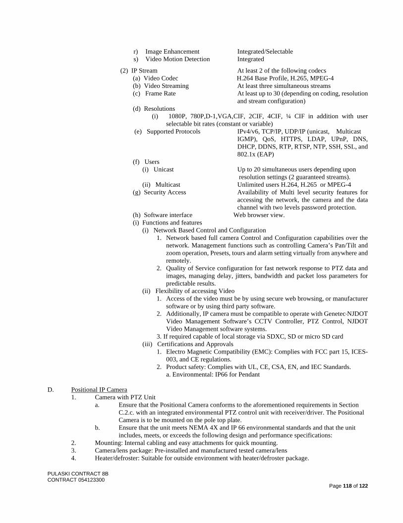
PULASKI CONTRACT 8B CONTRACT 054123300
Page 118 of 122
r) Image Enhancement Integrated/Selectable s) Video Motion Detection Integrated
(2) IP Stream At least 2 of the following codecs (a) Video Codec H.264 Base Profile, H.265, MPEG-4 (b) Video Streaming At least three simultaneous streams (c) Frame Rate At least up to 30 (depending on coding, resolution
and stream configuration) (d) Resolutions
(i) 1080P, 780P,D-1,VGA,CIF, 2CIF, 4CIF, ¼ CIF in addition with user selectable bit rates (constant or variable)
(e) Supported Protocols IPv4/v6, TCP/IP, UDP/IP (unicast, Multicast IGMP), QoS, HTTPS, LDAP, UPnP, DNS, DHCP, DDNS, RTP, RTSP, NTP, SSH, SSL, and 802.1x (EAP)
(f) Users (i) Unicast Up to 20 simultaneous users depending upon
resolution settings (2 guaranteed streams). (ii) Multicast Unlimited users H.264, H.265 or MPEG-4
(g) Security Access Availability of Multi level security features for accessing the network, the camera and the data channel with two levels password protection.
(h) Software interface Web browser view. (i) Functions and features
(i) Network Based Control and Configuration 1. Network based full camera Control and Configuration capabilities over the
network. Management functions such as controlling Camera’s Pan/Tilt and zoom operation, Presets, tours and alarm setting virtually from anywhere and remotely.
2. Quality of Service configuration for fast network response to PTZ data and images, managing delay, jitters, bandwidth and packet loss parameters for predictable results.
(ii) Flexibility of accessing Video 1. Access of the video must be by using secure web browsing, or manufacturer
software or by using third party software. 2. Additionally, IP camera must be compatible to operate with Genetec NJDOT
Video Management Software’s CCTV Controller, PTZ Control, NJDOT Video Management software systems.
3. If required capable of local storage via SDXC, SD or micro SD card (iii) Certifications and Approvals
1. Electro Magnetic Compatibility (EMC): Complies with FCC part 15, ICES-003, and CE regulations.
2. Product safety: Complies with UL, CE, CSA, EN, and IEC Standards. a. Environmental: IP66 for Pendant
D. Positional IP Camera 1. Camera with PTZ Unit
a. Ensure that the Positional Camera conforms to the aforementioned requirements in Section C.2.c. with an integrated environmental PTZ control unit with receiver/driver. The Positional Camera is to be mounted on the pole top plate.
b. Ensure that the unit meets NEMA 4X and IP 66 environmental standards and that the unit includes, meets, or exceeds the following design and performance specifications:
2. Mounting: Internal cabling and easy attachments for quick mounting. 3. Camera/lens package: Pre-installed and manufactured tested camera/lens 4. Heater/defroster: Suitable for outside environment with heater/defroster package.
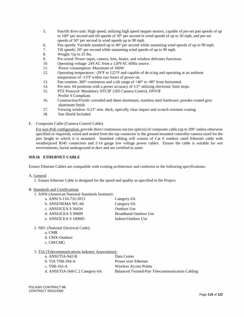
PULASKI CONTRACT 8B CONTRACT 054123300
Page 119 of 122
5. Pan/tilt drive unit: High speed, utilizing high speed stepper motors, capable of pre-set pan speeds of up to 100° per second and tilt speeds of 30° per second in wind speeds of up to 50 mph, and pre-set speeds of 50° per second in wind speeds up to 90 mph.
6. Pan speeds: Variable standard up to 40° per second while sustaining wind speeds of up to 90 mph. 7. Tilt speeds: 20° per second while sustaining wind speeds of up to 90 mph. 8. Weight: Up to 25 lbs. 9. Pre-wired: Power input, camera, lens, heater, and window defroster functions. 10. Operating voltage: 24VAC from a 120VAC 60Hz source. 11. Power consumption: Maximum of 160W 12. Operating temperature: -29°F to 122°F and capable of de-icing and operating at an ambient
temperature of -13°F within two hours of power on. 13. Pan rotation: 360° continuous and a tilt range of +40° to -90° from horizontal. 14. Pre-sets: 64 positions with a preset accuracy of 1/2° utilizing electronic limit stops. 15. PTZ Protocol: Mandatory NTCIP 1205 Camera Control, ONVIF Profile S Compliant. 16. Construction/Finish: extruded and sheet aluminum; stainless steel hardware; powder-coated grey
aluminum finish 17. Viewing window: 0.23" min. thick, optically clear impact and scratch resistant coating 18. Sun Shield Included
E. Composite Cable (Camera Control Cable) For non-PoE configuration, provide direct continuous run (no splices) of composite cable (up to 200’ unless otherwise specified or required), wired and sealed from the top connector to the ground mounted controller camera sized for the pier height to which it is mounted. Standard cabling will consist of Cat 6 outdoor rated Ethernet cable with weatherproof RJ45 connectors and 2-14 gauge low voltage power cables. Ensure the cable is suitable for wet environments, burial underground in duct and are certified to same.
918.16 ETHERNET CABLE
Ensure Ethernet Cables are compatible with existing architecture and conforms to the following specifications: A. General
1. Ensure Ethernet Cable is designed for the speed and quality as specified in the Project. B. Standards and Certifications
1. ANSI (American National Standards Institute): a. ANSI S-116-732-2013 Category 6A b. ANSI/NEMA WC-66 Category 6A c. ANSI/ICEA S 56434 Outdoor Use d. ANSI/ICEA S 99689 Broadband Outdoor Use e. ANSI/ICEA S 100685 Indoor/Outdoor Use
2. NEC (National Electrical Code):
a. CMR b. CMX-Outdoor c. CM/CMG
3. TIA (Telecommunications Industry Association):
a. ANSI/TIA-942-B Data Center b. TIA TSB-184-A Power over Ethernet c. TSB-162-A Wireless Access Points d. ANSI/TIA-568-C.2 Category 6A Balanced Twisted-Pair Telecommunication Cabling
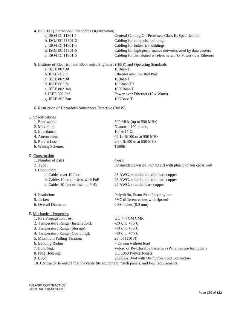
PULASKI CONTRACT 8B CONTRACT 054123300
Page 120 of 122
4. ISO/IEC (International Standards Organization): a. ISO/IEC 11801-1 General Cabling On-Premises; Class EA Specification b. ISO/IEC 11801-2 Cabling for enterprise buildings c. ISO/IEC 11801-3 Cabling for industrial buildings d. ISO/IEC 11801-5 Cabling for high-performance networks used by data centers e. ISO/IEC 11801-6 Cabling for distributed wireless networks Power over Ethernet
5. Institute of Electrical and Electronics Engineers (IEEE) and Operating Standards:
a. IEEE 802.3d 10Base-T b. IEEE 802.3i Ethernet over Twisted Pair c. IEEE 802.3d 10Base-T d. IEEE 802.3u 100Base-TX e. IEEE 802.3ab 1000Base-T f. IEEE 802.3af Power over Ethernet (15.4 Watts) g. IEEE 802.3an 10GBase-T
6. Restriction of Hazardous Substances Directive (RoHS) C. Specifications
1. Bandwidth: 500 MHz (up to 550 MHz) 2. Maximum Distance: 100 meters 3. Impedance: 100 ± 15 Ω 4. Attenuation: 62.1 dB/100 m at 550 MHz 5. Return Loss: 2.6 dB/100 m at 550 MHz 6. Wiring Scheme: T568B
D. Construction
1. Number of pairs 4-pair 2. Type: Unshielded Twisted Pair (UTP) with plastic or foil cross web 3. Conductor:
a. Cables over 10 feet: 23 AWG, stranded or solid bare copper b. Cables 10 feet or less, with PoE: 23 AWG, stranded or solid bare copper c. Cables 10 feet or less, no PoE: 24 AWG, stranded bare copper
4. Insulation: Polyolefin, Foam Skin Polyethylene 5. Jacket: PVC different colors with ripcord 6. Overall Diameter: 0.33 inches (8.0 mm)
E. Mechanical Properties
1. Fire Propagation Test: UL 444 CM CMR 2. Temperature Range (Installation): -20℃ to +75℃ 3. Temperature Range (Storage): -40℃ to +75℃ 4. Temperature Range (Operating): -40℃ to +75℃ 5. Maximum Pulling Tension: 25 lbf (110 N) 6. Bending Radius: > 25 mm without load 7. Bundling: Velcro or Re-Closable Fasteners (Wire ties are forbidden) 8. Plug Housing: UL 1863 Polycarbonate 9. Boot: Snagless Boot with 50-micron Gold Connectors 10. Contractor to ensure that the cable fits equipment, patch panels, and PoE requirements.
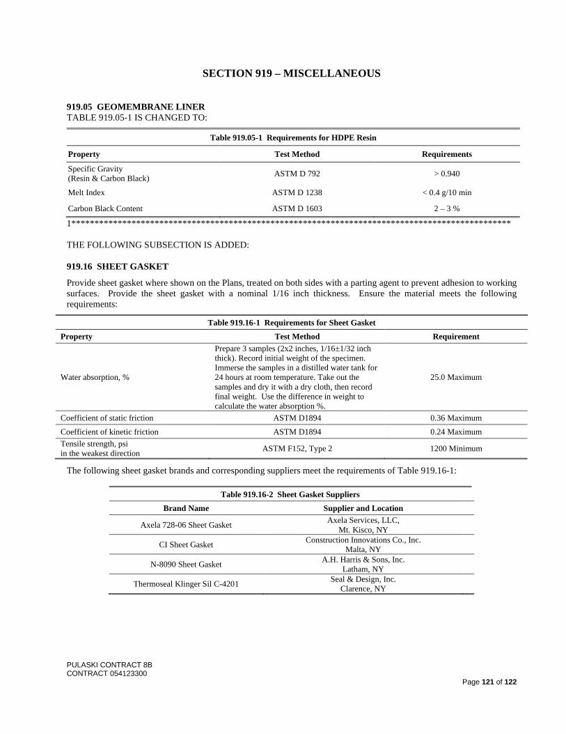
PULASKI CONTRACT 8B CONTRACT 054123300
Page 121 of 122
SECTION 919 – MISCELLANEOUS
919.05 GEOMEMBRANE LINER TABLE 919.05-1 IS CHANGED TO:
Table 919.05-1 Requirements for HDPE Resin
Property Test Method Requirements
Specific Gravity (Resin & Carbon Black) ASTM D 792 > 0.940
Melt Index ASTM D 1238 < 0.4 g/10 min
Carbon Black Content ASTM D 1603 2 – 3 %
1*********************************************************************************************** THE FOLLOWING SUBSECTION IS ADDED:
919.16 SHEET GASKET
Provide sheet gasket where shown on the Plans, treated on both sides with a parting agent to prevent adhesion to working surfaces. Provide the sheet gasket with a nominal 1/16 inch thickness. Ensure the material meets the following requirements:
Table 919.16-1 Requirements for Sheet Gasket Property Test Method Requirement
Water absorption, %
Prepare 3 samples (2x2 inches, 1/16±1/32 inch thick). Record initial weight of the specimen. Immerse the samples in a distilled water tank for 24 hours at room temperature. Take out the samples and dry it with a dry cloth, then record final weight. Use the difference in weight to calculate the water absorption %.
25.0 Maximum
Coefficient of static friction ASTM D1894 0.36 Maximum
Coefficient of kinetic friction ASTM D1894 0.24 Maximum Tensile strength, psi in the weakest direction ASTM F152, Type 2 1200 Minimum
The following sheet gasket brands and corresponding suppliers meet the requirements of Table 919.16-1:
Table 919.16-2 Sheet Gasket Suppliers Brand Name Supplier and Location
Axela 728-06 Sheet Gasket Axela Services, LLC, Mt. Kisco, NY
CI Sheet Gasket Construction Innovations Co., Inc. Malta, NY
N-8090 Sheet Gasket A.H. Harris & Sons, Inc. Latham, NY
Thermoseal Klinger Sil C-4201 Seal & Design, Inc. Clarence, NY
PULASKI CONTRACT 8B CONTRACT 054123300
Page 122 of 122
DIVISION 1000 – EQUIPMENT
SECTION 1001 – TRAFFIC CONTROL EQUIPMENT
1001.03 TRAFFIC CONTROL TRUCK WITH MOUNTED CRASH CUSHIONS THE FIRST PARAGRAPH PART 1 IS CHANGED TO:
1. Meets crash-worthiness requirements as specified in 159.03.02.
SECTION 1009 – HMA PLANT EQUIPMENT
1009.01 HMA PLANT
A. Requirements for HMA Mixing Plants.
8. Safety. THE THIRD PARAGRAPH IS CHANGED TO:
When plant production occurs during night operations, provide permanently fixed lighting throughout the plant operations, plant laboratory, and truck scale areas to ensure a clear view of the operations. Also provide permanently mounted lighting at the sampling platforms to sufficiently illuminate the bed of the truck for inspection and sampling operations.

April 2019
State Funded Project Attachment 1 – Small Business Enterprise Utilization Page 1 of 8
STATE FUNDED PROJECT ATTACHMENT 1
SMALL BUSINESS ENTERPRISE UTILIZATION ON WHOLLY STATE FUNDED PROJECTS A. Utilization of Small Business Enterprises Businesses as Subcontractors, Transaction Expeditors,
Regular Dealers, Manufacturers and Truckers. The Department advises the Contractor and subcontractor that failure to carry out the requirements set forth in this attachment constitutes a material breach of Contract and, after notification to the applicable State agency, may result in termination of the agreement or Contract by the Department or such remedy as the Department deems appropriate. Requirements set forth in this section shall also be physically included in all subcontract agreements in accordance with State of New Jersey requirements.
B. Policy. It is the policy of the Department that Small Business Enterprises (SBE), as defined in N.J.A.C. 17: 13-1.1 et seq., shall have the maximum opportunity to participate in the performance of contracts financed wholly with State funds. In this regard, the Department and all Contractors shall take all necessary and reasonable steps to ensure that registered Small Business Enterprises are utilized on, compete for, and perform on NJDOT construction contracts.
C. Definitions 1. Small Business Enterprise. A businesses which has its principal place of business in the State of
New Jersey; is independently owned and operated; has no more than 100 full-time employees; has gross revenues that do not exceed the applicable Federal revenue standards referenced at N.J.A.C. 17:13-2.1; and satisfies any additional eligibility standards under this chapter.
Small businesses with no more than 100 full-time employees will be registered in one of the following three categories:
a. Small business with gross revenues that do not exceed $3 million. b. Small businesses with gross revenues that do not exceed 50 percent of the applicable annual
revenue standards set forth in federal regulation at 13 CFR 121.201, incorporated herein by reference, and as may be adjusted periodically.
c. Small business with gross revenues that do not exceed the applicable annual revenue standards set forth in federal regulation at 13 CFR 121.201, incorporated herein by reference, as may be adjusted periodically.
The business must be independently owned and operated, with management being responsible for both its daily and long-term operation, as well as owning at least 51 percent interest in the business.
Businesses must be incorporated or registered with the Division of Revenue & Enterprise Services to do business in the State and have its principal place of business in New Jersey, defined when:
a. 51 percent or more of its employees work in New Jersey supported by paid New Jersey unemployment taxes or;
b. 51 percent or more of its business operations/activities occur in New Jersey supported by income and/or business tax returns.
c. The business must be a sole proprietorship, partnership, limited liability company or corporation with 100 or fewer employees in full-time positions, not including:
1. Seasonal and part-time employees employed for less than 90 days, if seasonal and casual part-time employment are common to that industry and
2. Consultants employed under contracts for which the business wants to be eligible as a small business.
2. Commercially Useful Function (CUF). A SBE performs a commercially useful function when it is responsible for execution of a distinct element of the work of a contract and carrying out its responsibility by actually performing, managing and supervising the work involved. To perform a
April 2019
State Funded Project Attachment 1 – Small Business Enterprise Utilization Page 2 of 8
commercially useful function, the SBE must also be responsible, with respect to materials and supplies used on the contract, for preparing the estimate, negotiating price, determining quality and quantity, ordering the material, arranging delivery, installing (where applicable), and paying for the material and supplies itself for the Project.
3. Transaction expeditor (broker). A SBE who arranges or expedites transactions and who arranges for material drop shipments.
4. SBE regular dealers. A firm that must be an established, regular business that engages, as its principal business and under its own name, in the purchase and sale or lease of the products in question. In addition, a regular dealer must own, operate or maintain a store, warehouse, or other establishment in which the materials, supplies, articles or equipment required under this Contract are bought, kept in stock, and regularly sold or leased to the public in the usual course of business.
5. SBE manufacturer. A firm that operates or maintains a factory or establishment that produces on the premises, the materials, supplies, articles, or equipment required for the Contract.
6. Good faith effort (GFE). Efforts to achieve a SBE goal or other requirement of N.J.A.C. 17:13-1.1 et seq. which by their scope, intensity, and appropriateness to the objective, can reasonably be expected to fulfill the program requirement. Efforts to include firms not certified as SBEs in the state where the contract is being let are consequently not good faith efforts to meet a SBE contract goal.
D. Compliance. The Contractor is responsible for compliance as specified in Section 105.
E Contractor SBE Goal Obligations. Ensure that SBEs have an equal opportunity to receive and participate in contracts and subcontracts financed in whole with State funds in performing work with the Department. Take all necessary and reasonable steps in accordance with the Contract to ensure that SBEs are given equal opportunity to compete for and to perform on the Department’s wholly State funded projects. Do not discriminate in the award and performance of any Contract obligation including, but not limited to, performance of obligations on wholly State funded contracts, as specified in Section 107.
1. Post Award Obligations
a. Give SBEs equal consideration with non-small business firms in negotiation for any subcontracts, purchase orders or leases.
b. Attempt to obtain qualified SBEs to perform the work. A directory of registered Small Businesses Enterprise firms can be found in the New Jersey Selective Assistance Vendor Information (NJSAVI) database online at: https://www20.state.nj.us/TYTR_SAVI/vendorSearch.jsp
2. Affirmative Action After Award of the Contract
a. Subletting. If at any time following the award of the Contract, the Contractor intends to sublet any portion(s) of the work under said Contract, or intends to purchase material or lease equipment not contemplated during preparation of bids, take affirmative action:
(1) Notify the RE, in writing, of the type and approximate value of the work which the Contractor intends to accomplish by such subcontract, purchase order or lease.
(2) Submit the Post-Award SBE Certification Form to the Regional Supervising Engineer with the application to sublet, or prior to purchasing material or leasing equipment. Obtain Post Award SBE Certification forms from the RE.
(3) Efforts made to identify and retain a SBE as a replacement subcontractor, lower tier subcontractor, transaction expeditor, regular dealer, supplier, manufacturer or trucker when the arrangements with the original SBE prove unsuccessful, shall be followed as specified for SBE subcontractors in Section 108. Work in the category concerned shall not begin until such approval is granted in writing by the Department.
(4) Notification of a SBE subcontractor’s termination will be the same as for SBE subcontractors, specified in Section 108. Send notice in writing to the Department through the RE, with a copy to DCR/AA. Said termination notice will include the firm’s ethnic classification, whether the firm is a SBE and the detailed reason(s) for termination.
b. Selection and Retention of Subcontractors. Do not discriminate in the selection and retention of subcontractors, including procurement of materials and leases of equipment as specified in
April 2019
State Funded Project Attachment 1 – Small Business Enterprise Utilization Page 3 of 8
108.01. Provide the RE with a listing of firms, organizations or enterprises solicited and those utilized as subcontractors on the proposed Project. Such listing shall clearly delineate which firms are classified as SBEs. Provide the RE with subcontract agreements for all subcontractors performing work on the Contract as specified in Section 108.
(1) Efforts made to identify and retain a SBE as a replacement subcontractor, lower tier subcontractor, transaction expeditor, regular dealer, supplier, manufacturer or trucker when the arrangements with the original SBE prove unsuccessful, shall be the same as for SBE subcontractors and submitted as specified in Section 108. Work in the category concerned shall not begin until such approval is granted in writing by the Department.
(2) Notification of a SBE firm’s termination will be as specified in Subsection 108.01. Send notice in writing to the Department through the RE. Said termination notice will include the firm’s ethnic classification, whether the firm is a SBE and the detailed reason(s) for termination.
c. Meeting Contract SBE Goal. Report attainment toward meeting the Contract SBE goal by submitting monthly, all SBE participation, to the Department’s RE and DCR/AA Contract Compliance Unit using the CR-267 – Monthly Report of Utilization of DBE/ESBE or SBE form. The form is due by the 5th of the month, and must list all SBEs used on the Contract to meet the Contract goal, the specific Contract work items each SBE is performing, whether the SBE is performing full or partial work on the items, and the amount paid to each SBE each month. Failure to report the information, and accurately report it may result in payment being delayed or withheld as specified in Section 105, assessing sanctions, or termination of the Contract as specified in Section 108.
d. Termination, Substitution or Replacement of SBEs. Make good faith efforts to replace a SBE that is terminated or has otherwise failed to complete its work on the Contract with another registered SBE, to the extent needed to meet the Contract SBE goal. Notify the DCR/AA immediately of the SBE’s inability or unwillingness to perform and provide reasonable documented evidence. Prior to termination, substitution or replacement of a SBE subcontractor, lower-tier subcontractor, transaction expeditor, regular dealer, supplier, manufacturer or trucker, submit a Revised CR-266 – Schedule of DBE.ESBE/SBE Participation form to the Department naming the replacement SBE firm(s), type of work performed, specific Contract work items, whether the SBE is performing full or partial work on the items, dollar value and percent of total Contract for each SBE firm. Submit detailed written explanation of why each change is being made, including documented evidence of good faith effort(s) with the submission of the revised Form CR- 266. Submit along with the revised CR-266: 1) a completed Confirmation of SBE Firm (Form CR-273) to demonstrate direct written confirmation from each SBE firm participating on the Contract, confirming the kind and amount of work that was provided on the Contractor’s CR-266, and if applicable; 2) a completed SBE Regular Dealer/Supplier Verification (Form CR-272) for all SBE Regular Dealers/Suppliers listed on the revised CR-266; and if applicable, 3) a completed SBE Trucking Verification (Form CR-274) for all SBE truckers listed on the revised CR-266 form. The Contractor is not permitted to complete any portion of the CR-273, CR-272 or CR-274 forms. Termination, substitution or replacement of SBEs shall be made as specified in Section 108. Termination or replacement of SBE cannot be made without prior written approval of the Department as per 108.01.
e. Submission of Good Faith Effort Documentation. If the Contractor is unable to meet the Contract goal for SBE participation, submit to the DCR/AA for review and approval, documented evidence of good faith efforts along with the monthly CR-267 form. This submission must include written details addressing each of the good faith efforts outlined in the Contract. Submittal of such information does not imply DCR/AA approval.
F. SBE Goals for this Contract. This Contract includes a goal of awarding 9 percentage of the Total Contract Price to subcontractors qualifying as SBEs.
NOTE: SUBCONTRACTING GOALS ARE NOT APPLICABLE IF THE PRIME CONTRACTOR IS A REGISTERED SMALL BUSINESS ENTERPRISE (SBE) FIRM.
April 2019
State Funded Project Attachment 1 – Small Business Enterprise Utilization Page 4 of 8
The Department’s DCR/AA has sole authority to determine whether the Contractor met the Contract goal or made adequate good faith efforts to do so. If the DCR/AA determines that the Contractor has failed to meet the Contract SBE goal or made adequate good faith efforts to do so, the Department will follow Section 105.
G. Counting SBE Participation. 1. Each SBE is subject to a registration procedure to ensure its SBE eligibility status prior to the award
of Contract. All SBEs working on the Contract must be registered SBEs. Only Small Business Enterprises registered prior to the date of bid, or prospective Small Business Enterprises that have submitted to the New Jersey Commerce and Economic Growth Commission on or before the day of bid, a completed “State of New Jersey Small Business Vendor Registration Form” and all the required support documentation, will be considered in determining whether the Contractor has met the established Contract SBE goal. Early submission of required documentation is encouraged.
2. The Department determines the percentage of SBE participation that will be counted toward the Contract SBE goal. Once a firm is determined to be a bona fide SBE by the New Jersey Commerce and Growth Commission, the total dollar value of the contract awarded to the SBE is counted toward the applicable goal.
3. The Contractor will count SBE participation toward the Contract SBE goal only the value of the work actually performed by a SBE when that SBE performs a commercially useful function in the work of a contract as per Section H of this Special Provision Attachment.
4. If a Contractor is part of a Joint Venture and one or more of the Sole Proprietorships, Partnerships, Limited Liability companies or Corporations comprising the Joint Venture is a registered SBE, the actual payments made to the Joint Venture for work performed by the SBE member, will be applied toward the Contract SBE goal. Payments made to the Joint Venture for work performed by a non-small business firm will not be applied toward the Contract SBE goal.
5. If the Contractor is a registered SBE, payments made to the Contractor for work that the Contractor is registered to perform, and performed by the Contractor will be applied toward the Contract SBE goal. Payments made to the Contractor for work performed by non-SBEs will not be applied toward the Contract SBE goal.
6. When a SBE subcontracts part of the work of its contract to another firm, the value of the subcontracted work may be counted towards the SBE goal only if the subcontractor itself is a SBE. Work that a SBE subcontracts to a non-SBE firm does not count toward the Contract SBE goal.
H. Commercially Useful Function 1. Performance of Work. The SBE must perform the work with their own permanent employees, or
employees recruited through traditional recruitment and/or employment centers. SBEs must employ and control their own workforce, and cannot share employees with the Contractor, other subcontractors on the present Project, or the renter-lessor of equipment being used on the present Project. The SBE firm must be responsible for all payroll and labor compliance requirements for all of their employees performing work on the Contract. Direct or indirect payments by any other contractor are not allowed.
2. Managing Work. The SBE must manage the work themselves including the scheduling of work operations, ordering of equipment and materials, hiring/firing of employees, including supervisory employees, and preparing and submitting certified payrolls. The SBE must supervise their portion of daily work operations of the Project. With respect to materials and supplies used on the Contract, the SBE must be responsible for preparing the estimate, negotiating price, determining quantity and quality, ordering the material, arranging delivery, installing, (where applicable), and paying for the material and supplies for the Project.
3. Responsibility of Work. A SBE must perform or exercise responsibility for at least 30 percent of the total cost of its contract with its own workforce. The SBE must not subcontract a greater portion of the work of a contract than would be expected on the basis of normal industry practice for the type of work involved.
4. Equipment of SBE. The SBE must perform the work stated in the subcontract with their own equipment, whether owned or leased and operated on a long term agreement, not an ad hoc or
April 2019
State Funded Project Attachment 1 – Small Business Enterprise Utilization Page 5 of 8
contract by contract agreement. The equipment must be owned by the SBE firm, or leased/rented from traditional equipment lease/rental sources. The equipment will not belong to the Contractor, any other subcontractor or lower tier subcontractors on the current Project, or supplier of materials being installed by the SBE firm.
5. Lease of Equipment. A SBE firm may lease specialized equipment from a contractor, but not from the Contractor, if it is consistent with normal industry practices and at rates competitive for the area. Rental agreements must be for short periods of time, specify the terms of the agreement and involve specialty equipment to be used at the job site. The lease may allow the operator to remain on the lessor’s payroll, if it is the generally accepted industry practice but the operation of the equipment must be subject to full control by the SBE. The SBE shall provide the operator for non-specialized equipment, and is responsible for all payroll and labor compliance requirements. A separate lease agreement is required.
6. SBE Trucking. SBE trucking companies must perform a commercially useful function. Contrived arrangements for the purpose of meeting SBE goals will not be allowed. The SBE must be responsible for the management and supervision of the entire trucking operation on a contract-by-contract basis, and must own and operate at least one fully, licensed, insured and operational truck used on the Contract.
The SBE trucking firm is not permitted to obtain trucks from the Contractor to perform work on the Project. The SBE may lease trucks from a subcontractor working on the Project, provided the trucks are obtained from the subcontractor prior to the Project letting. Bona fide lease agreements must be for the length of time needed by the SBE on the Contract and signed by both the SBE and the firm(s), either certified SBE or non-SBE, from which the trucks will be leased. Leases must indicate that the SBE has exclusive use and control over the truck. All leased trucks must display the name and USDOT identification number issued for interstate commerce, of the SBE firm, on the outside of the truck. SBE firms are expected to use the same trucks for SBE credit on all projects so use of leased vehicles on a project-by-project basis is not permitted.
The Contractor shall have signed Hiring Agreements. Submit copies of these signed Hiring Agreements, and copies of all signed lease agreements to the RE prior to the trucking firm’s commencing work on the Project. Prior to the SBE trucking firm beginning work on the Contract, SBE Trucking firms will be required to complete the SBE Trucking Verification (Form CR-274). The SBE and Contractor must sign the form and the Contractor submit the original CR-274 form directly to the Department’s RE, with a copy submitted to the DCR/AA. The Contractor is not permitted to complete any portion of the CR-274 form. The Contractor must prepare, sign and submit along with the CR-267 – Monthly Report of Utilization of DBE/ESBE or SBE form, a Monthly Trucking Verification form (CR-271), identifying each truck owner, SBE Certification number, company name and address, truck number, and commission or amount paid for all SBE and non-SBE truckers performing work on the Project. Also, submit the form to the Department as per Section E of this Special Provision for the DCR/AA’s review, approval and determination of credit toward the Contract goal. Failure to submit the forms may result in denial or limit of credit toward the Contract SBE goal, payment being delayed or withheld as specified in Section 105, assessing sanctions or termination of the Contract as specified in Section 108.
7. SBE Regular Dealers. SBE regular dealers must be an established, regular business that engages, as its principal business and under its own name, in the purchase and sale or lease of the products in question. In addition, a regular dealer must own, operate or maintain a store, warehouse, or other establishment in which the materials, supplies, articles or equipment of the general character described by the specifications and required under this Contract are bought, kept in stock, and regularly sold or leased to the public in the usual course of business.
8. SBE Manufacturers. SBE manufacturers must be a firm that operates or maintains a factory or establishment that produces on the premises, the materials, supplies, articles, or equipment required for this Contract.
April 2019
State Funded Project Attachment 1 – Small Business Enterprise Utilization Page 6 of 8
9. The Contractor shall not use a SBE solely for the purpose of acting as an extra participant in a transaction, a contract or the Contract through which funds are passed in order to obtain the appearance of SBE participation.
I. Good Faith Effort. To demonstrate good faith efforts to meet the Contract SBE goal, a Contractor shall, on an ongoing basis, adequately document the steps it takes to obtain SBE participation, including but not limited to the following: 1. Conducting market research to identify qualified potential small business subcontractors and
suppliers and soliciting through all reasonable and available means, the interest of registered SBEs that have the capability to perform the work of the Contract. This may include attendance at pre-bid and business matchmaking meetings and events, advertising and/or written notices, posting of Notices of Sources Sought and/or Requests for Proposals, written notices or emails to all registered SBEs listed in the New Jersey Selective Assistance Vendor Information (NJSAVI) database that specialize in the areas of work desired (as noted in SAVI) and which are located in the area or surrounding areas of the Project.
Solicit this interest as early in the acquisition process as practicable to allow the SBEs to respond to the solicitation and submit a timely offer for the subcontract. Determine with certainty if the SBEs are interested by taking appropriate steps to follow up initial solicitations.
Request a listing of small businesses from the New Jersey Department of the Treasury, Division of Property Management and Construction if none are known to the Contractor
2. Selecting portions of the work to be performed by SBEs in order to increase the likelihood that the SBE goals will be achieved. This includes, where appropriate, breaking out Contract work items into economically feasible units (for example, smaller tasks or quantities) to facilitate SBE participation, even when the Contractor might otherwise prefer to perform these work items with its own forces. This may include, where possible, establishing flexible timeframes for performance and delivery schedules in a manner that encourages and facilitates SBE participation.
3. Providing all potential SBE subcontractors with detailed information about the plans, specifications, and requirements of the Contract in a timely manner to assist them in responding to a solicitation with their offer for the subcontract. Attempt to contact all potential subcontractors on the same day and use similar methods to contact them.
4. Negotiating in good faith with interested SBEs. Make a portion of the work available to SBE subcontractors and suppliers and select those portions of the work or material needs consistent with the available SBE subcontractors and suppliers, so as to facilitate SBE participation. Evidence of such negotiation includes the names, addresses, and telephone numbers of SBEs that were considered; a description of the information provided regarding the plans and specifications for the work selected for subcontracting; and evidence as to why additional Agreements could not be reached for SBEs to perform the work.
Consider a number of factors in negotiating with subcontractors, including SBE subcontractors. Take a firm’s price and capabilities as well as Contract goals into consideration. The fact that there may be some additional costs involved in finding and using SBEs is not in itself sufficient reason for failure to meet the Contract SBE goal, as long as such costs are reasonable. The ability or desire of a Contractor to perform the work of a Contract with its own organization does not relieve the responsibility to make good faith efforts. Contractors are not, however, required to accept higher quotes from SBEs if the price difference is excessive or unreasonable.
5. Not rejecting SBEs as being unqualified without sound reasons based on a thorough investigation of their capabilities. The contractor’s standing within its industry, membership in specific groups, organizations, or associations and political or social affiliations (for example union vs. non-union status) are not legitimate causes for the rejection or non-solicitation of bids in the Contractor’s efforts to meet the Contract SBE goal. Another practice considered an insufficient good faith effort is the rejection of the SBE because its quotation for the work was not the lowest received. However, nothing in this paragraph shall be construed to require the Bidder to accept unreasonable quotes in order to satisfy the Contract SBE goal.

April 2019
State Funded Project Attachment 1 – Small Business Enterprise Utilization Page 7 of 8
Inability to find a replacement SBE at the original price is not alone sufficient to support a finding that good faith efforts have been made to replace the original SBE. The fact that the Contractor has the ability and/or desire to perform the contract work with its own forces does not relieve the Contractor of the obligation to make good faith efforts to find a replacement SBE, and it is not a sound basis for rejecting a prospective replacement SBE’s reasonable quote. Attempt, wherever possible, to negotiate prices with potential subcontractors which submitted higher than acceptable price quotes.
Keep a record of efforts, including the names of businesses contacted and the means and results of such contacts.
6. Making efforts to assist interested SBEs in obtaining bonding, lines of credit, or insurance as required by the recipient or Contractor.
7. Making efforts to assist interested SBEs in obtaining necessary equipment, supplies, materials, or related assistance or services.
If the Contractor fails to meet the Contract SBE goal, they must submit documented evidence of good faith effort(s) to meet the goal with the CR-268 final SBE Report to the DCR/AA for review and approval. Submittal of such information does not imply DCR/AA approval. The Department’s DCR/AA has sole authority to determine whether the Contractor met the Contract SBE goal or made adequate good faith efforts to do so. If the DCR/AA determines that the Contractor has failed to meet the Contract SBE goal or made adequate good faith effort to do so, the Department will follow Section 105.
J. Submission of Affirmative Action Program Contractors, subcontractors and professional service firms performing work for the Department are required to submit their company’s Affirmative Action Program annually to the DCR/AA. Contractors must have an approved Affirmative Action Program on file in the DCR/AA no later than seven (7) State business days after the date of bid opening. No recommendations to award will be made without an approved Affirmative Action Program on file in the DCR/AA. Ensure subcontractors and professional service firms have an approved Affirmative Action Plan on file in the DCR/AA prior to their beginning work on a particular project.
The Annual Affirmative Action Program will include, but is not limited to the following:
1. Copy of company’s comprehensive EEO/Affirmative Action Plan, with a cover page that includes the company name and address, and signature of the Chief Executive or EEO Officer.
2. Copy of document designating the company’s corporate EEO Officer, including the name, address and contact telephone number for the officer, and signature of the Chief Executive or President, on company letterhead.
3. Copy of the company’s EEO Policy Statement on company letterhead, dated and signed by the Chief Executive and the EEO Officer.
4. Copy of the company’s Sexual Harassment Policy on company letterhead. 5. EEO Legend such as letterhead, envelope, or published advertisement showing the company is an
equal opportunity employer. 6. Copy of document designating the company’s SBE Liaison Officer to administer the firm’s Small
Business Program. 7. SBE Affirmative Action Plan which is an explanation of affirmative action methods intended to be used
to seek out and consider SBEs as subcontractors, material suppliers or equipment lessors. This refers to the Contractor’s ongoing responsibility, i.e., Small Business Enterprise/Affirmative Action activities after the award of the Contract and for the duration of the Contract.
K. SBE Liaison Officer. Designate a SBE Liaison Officer who shall be responsible for the administration of your SBE program in accordance with the Contract, and ensuring that the Contractor complies with all provisions of the SBE Program.
L. Consent by Department to Subletting. The Department will not approve any subcontract proposed by the Contractor unless and until said Contractor has complied with the terms of the Contract.
M. Conciliation. In cases of alleged discrimination regarding these and all equal employment opportunity provisions and guidelines, investigations and conciliation will be undertaken by the DCR/AA.
April 2019
State Funded Project Attachment 1 – Small Business Enterprise Utilization Page 8 of 8
N. Documentation 1. Requiring of Information. The Department or the State funding agencies may at any time require
information as specified in Section 107.02 and deemed necessary in the judgment of the Department to ascertain the compliance of any Bidder, Contractor or subcontractor with the terms of the Contract.
2. Record and Reports. The Contractor, subcontractors and other sub-recipients will keep such records as are necessary to determine compliance with its SBE obligations. These records kept will be designed to indicate:
a. The names of SBE contractors, subcontractors, transaction expeditors and material suppliers contacted for work on the Contract, including when and how contacted, and the specific Contract work items and other information provided to each.
b. Work, services and materials which are not performed or supplied by the Contractor. c. The actual dollar value of work subcontracted and awarded to SBEs, including specific Contract
work items and cost of each work item. d. The progress being made and efforts taken in seeking out and utilizing SBEs to include:
solicitations, specific Contract work items and the quotes and bids regarding those specific Contract work items, supplies, leases, or other contract items, etc.
e. Detailed written documentation of all correspondence, contacts, telephone calls, etc., including names and dates/times, to obtain the services of SBEs on the Contract.
f. Records of all SBEs and non-SBEs who have submitted quotes/bids to the Contractor on the Contract.
g. Monthly CR-267 – Monthly Report, Utilization of DBE/ESBE or SBE, and other reports required for submission to the Department, hiring agreements, subcontracts, lease agreements, equipment rental agreements, supply tickets, delivery slips, payment information, and other records documenting SBE utilization on the Contract.
h. Documentation outlining EEO workforce information for the Contract. i. Documentation outlining EEO and Affirmative Action efforts made in the administration and
performance of the Contract.
3. Submission of Reports, Forms and Documentation. Submit reports, forms and documentation, as required by the Department, on those contracts and other business transactions executed with SBEs in such form and manner as may be prescribed by the Department. Failure to submit the required forms, reports or other documentation as required may result in payment being delayed or withheld as specified in Section 105, assessing sanctions, or termination of the contract as specified in Section 108. Submission of falsified forms, reports or other required documentation may result in termination of the Contract as specified in Section 108, investigation by the Department’s Inspector General, and prosecution by the State Attorney General’s Office.
4. Maintaining Records. All records must be maintained for a period of three (3) years following acceptance of final payment and will be available for inspection by the Department, or the State funding agencies.
O. Prompt Payment to Subcontractors. Payment to subcontractors, equipment lessors, suppliers and manufacturers is made in accordance with Section 109.
P. Non-Compliance. Failure by the Contractor to comply with the SBE program, rules and regulations in the administration of the Contract may result in denial or limit of credit toward the Contract SBE goal, payment being delayed or withheld as specified in Section 105, assessing sanctions, liquidated damages as specified in Section 108, default as specified in Section 108, debarment, or termination of the Contract as specified in Section 108. The Contractor may further be declared ineligible for future Department contracts.

June 2017
State Funded Project Attachment 2 – State Of NJ EEO Special Provisions for Wholly State Funded Projects Page 1 of 7
STATE FUNDED PROJECT ATTACHMENT 2
STATE OF NEW JERSEY EQUAL EMPLOYMENT OPPORTUNITY SPECIAL PROVISIONS FOR WHOLLY STATE FUNDED PROJECTS A. General. It is the policy of the New Jersey Department of Transportation (hereafter “NJDOT”) that its
contracts should create a workforce that reflects the diversity of the State of New Jersey. Therefore, contractors engaged by the Department to perform under a construction contract shall put forth a good faith effort to engage in recruitment and employment practices that further the goal of fostering equal opportunities to minorities and women.
The Contractor must demonstrate to the Department’s satisfaction that a good faith effort was made to ensure that minorities and women have been afforded equal opportunity to gain employment under the Department’s contract with the Contractor. Payment may be withheld from a Contractor’s contract for failure to comply with these provisions.
Evidence of a “good faith effort” includes, but is not limited to:
1. The Contractor shall recruit prospective employees through the New Jersey career connections website, managed by the Department of Labor and Workforce Development, available online at http://careerconnections.nj.gov/careerconnections/for_businesses.shtml
2. The Contractor shall keep detailed documented evidence of its efforts, including records of all individuals interviewed and hired, including the specific numbers of minorities and women;
3. The Contractor shall actively solicit and shall provide the Department with proof of solicitations for employment, including but not limited to advertisements in general circulation media, professional service publications and electronic media;
4. The Contractor shall provide evidence of efforts described at 2 above to the Department no less frequently than once every 12 months; and
5. The Contractor shall comply with the requirements set forth at N.J.A.C. 17:27-1.1 et seq.
The Contractor is required to implement and maintain a specific Affirmative Action Compliance Program of Equal Employment Opportunity in support of the New Jersey “Law Against Discrimination”, N.J.S.A. 10:5-31 et seq., and according to the Affirmative Action Regulations set forth at N.J.A.C. 17:27-1.1 et seq.
The provisions of N.J.S.A. 10:2-1 through 10:2-4 and N.J.S.A. 10:5-31 et seq., as amended and supplemented) dealing with discrimination in employment on public contracts, and the rules and regulations promulgated pursuant thereunto, are hereby made a part of this contract and are binding upon the Contractor.
Noncompliance by the Contractor with the requirements of the Affirmative Action program for Equal Employment Opportunity may be cause for delaying or withholding monthly and final payments pending corrective and appropriate measures by the Contractor to the satisfaction of the Department.
The Contractor will cooperate with the State agencies in carrying out its Equal Employment Opportunity obligations and in their review of its activities under the contract.
The Contractor and all its subcontractors, not including material suppliers, holding subcontracts of $2,500 or more, will comply with the following minimum specific requirement activities of Equal Opportunity and Affirmative Action set forth in these special provisions. The Contractor will include the following mandatory equal employment opportunity language in every subcontract of $2,500 or more with such modification of language in the provisions of such contracts as is necessary to make them binding on the subcontractor.
During the performance of this Contract, the contractor agrees as follows:
1. The Contractor or subcontractor, where applicable, will not discriminate against any employee or applicant for employment because of age, race, creed, color, national origin, ancestry, marital status, affectional or sexual orientation, gender identity or expression, disability, nationality or sex. The Contractor will ensure that equal employment opportunity is afforded to such applicants in recruitment and employment, and that employees are treated during employment, without regard to their age,
June 2017
State Funded Project Attachment 2 – State Of NJ EEO Special Provisions for Wholly State Funded Projects Page 2 of 7
race, creed, color, national origin, ancestry, marital status, affectional or sexual orientation, gender identity or expression, veteran’s status, disability, nationality or sex. Such equal employment opportunity shall include, but not be limited to the following: employment, upgrading, demotion, or transfer; recruitment or recruitment advertising; layoff or termination; rates of pay or other forms of compensation; and selection for training, including apprenticeship. The Contractor agrees to post in conspicuous places, available to employees and applicants for employment, notices to be provided by the Public Agency Compliance Officer setting forth provisions of this nondiscrimination clause.
2. The Contractor or subcontractor, where applicable will, in all solicitations or advertisements for employees placed by or on behalf of the Contractor, state that all qualified applicants will receive consideration for employment without regard to age, race, creed, color, national origin, ancestry, marital status, affectional or sexual orientation, gender identity or expression, disability, nationality or sex.
3. The Contractor or subcontractor will send to each labor union, with which it has a collective bargaining agreement, a notice, to be provided by the agency contracting officer, advising the labor union or workers' representative of the contractor's commitments under this act and shall post copies of the notice in conspicuous places available to employees and applicants for employment.
4. The Contractor or subcontractor, where applicable, agrees to comply with any regulations promulgated by the Treasurer, pursuant to N.J.S.A. 10:5-31 et seq., as amended and supplemented from time to time and the Americans with Disabilities Act.
5. When hiring or scheduling workers in each construction trade, the Contractor or subcontractor agrees to make good faith efforts to employ minority and women workers in each construction trade consistent with the targeted employment goal prescribed by N.J.A.C. l7:27-7.2; provided, however, that the NJ Department of Labor and Workforce Development, Construction EEO Monitoring Program, may, in its discretion, exempt a contractor or subcontractor from compliance with the good faith procedures prescribed by the following provisions, a, b, and c, as long as the NJ Department of Labor and Workforce Development, Construction EEO Monitoring Program is satisfied that the Contractor or subcontractor is employing workers provided by a union which provides evidence, in accordance with standards prescribed by the NJ Department of Labor and Workforce Development, Construction EEO Monitoring Program, that its percentage of active “card carrying” members who are minority and women workers is equal to or greater than the targeted employment goal established in accordance with N.J.A.C. 17:27-7.2. The Contractor or subcontractor agrees that a good faith effort shall include compliance with the following procedures:
a. If the Contractor or subcontractor has a referral agreement or arrangement with a union for a construction trade, the Contractor or subcontractor shall, within three business days of the contract award, seek assurances from the union that it will cooperate with the Contractor or sub-contractor as it fulfills its affirmative action obligations under this contract and in accordance with the rules promulgated by the Treasurer pursuant to N.J.S.A. 10:5-31 et. seq., as supplemented and amended from time to time and the Americans with Disabilities Act. If the Contractor or subcontractor is unable to obtain said assurances from the construction trade union at least five business days prior to the commencement of construction work, the Contractor or sub-contractor agrees to afford equal employment opportunities minority and women workers directly, consistent with this chapter. If the Contractor's or subcontractor's prior experience with a construction trade union, regardless of whether the union has provided said assurances, indicates a significant possibility that the trade union will not refer sufficient minority and women workers consistent with affording equal employment opportunities as specified in this chapter, the Contractor or subcontractor agrees to be prepared to provide such opportunities to minority and women workers directly, consistent with this chapter, by complying with the hiring or scheduling procedures prescribed under (B) below; and the Contractor or subcontractor further agrees to take said action immediately if it determines that the union is not referring minority and women workers consistent with the equal employment opportunity goals set forth in this chapter.
b. If good faith efforts to meet targeted employment goals have not or cannot be met for each construction trade by adhering to the procedures of (a.) above, or if the Contractor does not have a referral agreement or arrangement with a union for a construction trade, the Contractor or subcontractor agrees to take the following actions:
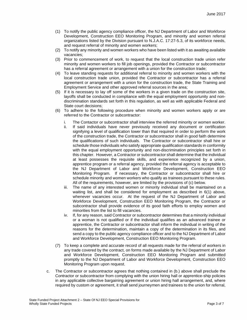
June 2017
State Funded Project Attachment 2 – State Of NJ EEO Special Provisions for Wholly State Funded Projects Page 3 of 7
(1) To notify the public agency compliance officer, the NJ Department of Labor and Workforce Development, Construction EEO Monitoring Program, and minority and women referral organizations listed by the Division pursuant to N.J.A.C. 17:27-5.3, of its workforce needs, and request referral of minority and women workers;
(2) To notify any minority and women workers who have been listed with it as awaiting available vacancies;
(3) Prior to commencement of work, to request that the local construction trade union refer minority and women workers to fill job openings, provided the Contractor or subcontractor has a referral agreement or arrangement with a union for the construction trade;
(4) To leave standing requests for additional referral to minority and women workers with the local construction trade union, provided the Contractor or subcontractor has a referral agreement or arrangement with a union for the construction trade, the State Training and Employment Service and other approved referral sources in the area;
(5) If it is necessary to lay off some of the workers in a given trade on the construction site, layoffs shall be conducted in compliance with the equal employment opportunity and non-discrimination standards set forth in this regulation, as well as with applicable Federal and State court decisions;
(6) To adhere to the following procedure when minority and women workers apply or are referred to the Contractor or subcontractor:
i. The Contactor or subcontractor shall interview the referred minority or women worker. ii. If said individuals have never previously received any document or certification
signifying a level of qualification lower than that required in order to perform the work of the construction trade, the Contractor or subcontractor shall in good faith determine the qualifications of such individuals. The Contractor or subcontractor shall hire or schedule those individuals who satisfy appropriate qualification standards in conformity with the equal employment opportunity and non-discrimination principles set forth in this chapter. However, a Contractor or subcontractor shall determine that the individual at least possesses the requisite skills, and experience recognized by a union, apprentice program or a referral agency, provided the referral agency is acceptable to the NJ Department of Labor and Workforce Development, Construction EEO Monitoring Program. If necessary, the Contractor or subcontractor shall hire or schedule minority and women workers who qualify as trainees pursuant to these rules. All of the requirements, however, are limited by the provisions of (c) below.
iii. The name of any interested women or minority individual shall be maintained on a waiting list, and shall be considered for employment as described in 6(1) above, whenever vacancies occur. At the request of the NJ Department of Labor and Workforce Development, Construction EEO Monitoring Program, the Contractor or subcontractor shall provide evidence of its good faith efforts to employ women and minorities from the list to fill vacancies.
iv. If, for any reason, said Contractor or subcontractor determines that a minority individual or a woman is not qualified or if the individual qualifies as an advanced trainee or apprentice, the Contractor or subcontractor shall inform the individual in writing of the reasons for the determination, maintain a copy of the determination in its files, and send a copy to the public agency compliance officer and to the NJ Department of Labor and Workforce Development, Construction EEO Monitoring Program.
(7) To keep a complete and accurate record of all requests made for the referral of workers in any trade covered by the contract, on forms made available by the NJ Department of Labor and Workforce Development, Construction EEO Monitoring Program and submitted promptly to the NJ Department of Labor and Workforce Development, Construction EEO Monitoring Program upon request.
c. The Contractor or subcontractor agrees that nothing contained in (b.) above shall preclude the Contractor or subcontractor from complying with the union hiring hall or apprentice-ship policies in any applicable collective bargaining agreement or union hiring hall arrangement, and, where required by custom or agreement, it shall send journeymen and trainees to the union for referral,

June 2017
State Funded Project Attachment 2 – State Of NJ EEO Special Provisions for Wholly State Funded Projects Page 4 of 7
or to the apprenticeship program for admission, pursuant to such agreement or arrangement. However, where the practices of a union or apprenticeship program will result in the exclusion of minorities and women or the failure to refer minorities and women consistent with the targeted county employment goal, the Contractor or subcontractor shall consider for employment persons referred pursuant to (b) above without regard to such agreement or arrangement; provided further, however, that the Contractor or subcontractor shall not be required to employ women and minority advanced trainees and trainees in numbers which result in the employment of advanced trainees and trainees as a percentage of the total workforce for the construction trade, which percentage significantly exceeds the apprentice to journey worker ratio specified in the applicable collective bargaining agreement, or in the absence of a collective bargaining agreement, exceeds the ratio established by practice in the area for said construction trade. Also, the Contractor or subcontractor agrees that, in implementing the procedures of (b) above, it shall, where applicable, employ minority and women workers residing within the geographical jurisdiction of the union.
The Contractor agrees to cooperate with the public agency in the payment of budgeted funds, as is necessary, for on-the-job and/or off-the-job programs for outreach and training of minorities and women.
The Contractor and its subcontractors shall furnish such reports or other documents to the NJ Department of Labor and Workforce Development, Construction EEO Monitoring Program as may be requested by the NJ Department of Labor and Workforce Development, Construction EEO Monitoring Program from time to time in order to carry out the purposes of these regulations, and public agencies shall furnish such information as may be requested by the NJ Department of Labor and Workforce Development, Construction EEO Monitoring Program for conducting a compliance investigation pursuant to N.J.A.C. 17:27-1.1 et seq..
The Contractor agrees to cooperate with the public agency in the payment of budgeted funds, as is necessary, for on-the-job and off-the-job programs for outreach and training of minority and female trainees employed on the construction projects.
B. Equal Employment Opportunity Policy. The Contractor agrees that it will accept and implement during the performance of this contract as its operating policy the following statement which is designed to further the provision of Equal Employment Opportunity to all persons without regard to their age, race, creed, color, national origin, ancestry, marital status, affectional or sexual orientation, gender identity or expression, disability, nationality or sex and to promote the full realization of Equal Employment Opportunity through a positive continuing program:
“It is the policy of this company that it will not discriminate against any employee or applicant for employment because of age, race, creed, color, national origin, ancestry, marital status, affectional or sexual orientation, gender identity or expression, disability, nationality or sex and that it will take Affirmative Action to ensure that applicants are recruited and employed and that employees are treated during employment without regard to their age, race, creed, color, national origin, ancestry, marital status, affectional or sexual orientation, gender identity or expression, disability, nationality or sex. Such action shall include, but not be limited to, the following: employment, upgrading, demotion or transfer; recruitment or recruitment advertising; layoff or termination; rates of pay or other forms of compensation; and selection for training, including apprenticeship.”
C. Equal Employment Opportunity Officer. Designate and make known to the Department’s contracting officers, an Equal Employment Opportunity Officer (hereafter “EEO Officer”) who will have the responsibility for and must be capable of effectively administering and promoting an active Equal Employment Opportunity program and be assigned adequate authority and responsibility to do so.
D. Dissemination of Policy. 1. Implementation. All members of the Contractor’s staff who are authorized to hire, supervise,
promote, and discharge employees, or who recommend such action, will be made fully cognizant of, and will implement, the Contractor’s Equal Employment Opportunity Policy and contractual responsibilities to provide Equal Employment Opportunity in each grade and classification of

June 2017
State Funded Project Attachment 2 – State Of NJ EEO Special Provisions for Wholly State Funded Projects Page 5 of 7
employment. To ensure that the above agreement will be met, the following actions will be taken as a minimum:
a. Initial Project Site Meeting. Conduct an initial Project site meeting with supervisory and personnel office employees before the start of work and then not less often than once every 6 months, at which time the Contractor’s Equal Employment Opportunity Policy and its implementation will be reviewed and explained. The EEO Officer will conduct the meetings.
b. EEO Obligations. Give all new supervisory or personnel office employees a thorough indoctrination by the EEO Officer covering all major aspects of the Contractor’s Equal Employment Opportunity obligations within 30 days following their reporting for duty with the Contractor.
c. All personnel who are engaged in direct recruitment for the Project will be instructed by the EEO Officer in the Contractor’s procedures for locating and hiring minority and women workers.
2. Take the following actions in order to make the Contractor’s Equal Employment Opportunity Policy known to all employees, prospective employees and potential sources of employees, i.e., schools, employment agencies, labor unions (where appropriate), college placement officers, etc.,:
a. Place notices and posters setting forth in the Contractor’s Equal Employment Opportunity policy, as set forth in Section 2 of these Equal Employment Opportunity Special Provisions in conspicuous places readily accessible to employees, applicants for employment and potential employees.
b. Bring the Contractor’s Equal Employment Opportunity Policy and the procedures to implement such policy to the attention of employees by means of meetings, employee handbooks, or other appropriate channels.
E. Recruitment 1. In all solicitations and advertisements for employees placed by or on behalf of the Contractor, the
Contractor will state that all qualified applicants will receive consideration for employment without regard to age, race, creed, color, national origin, ancestry, marital status, affectional or sexual orientation, gender identity or expression, veterans status, disability, nationality or sex. All such advertisements will be published in newspapers or other publications having a large circulation among minorities and women in the area from which the Project workforce would normally be derived.
2. Unless precluded by a valid bargaining agreement, conduct systematic and direct recruitment through public and private employee referral sources likely to yield qualified minority and women applicants, including, but not limited to state employment agencies, schools, colleges and minority and women organizations. Through their EEO Officer, identify sources of potential minority and women employees, and establish with such identified sources procedures whereby minority and women applicants may be referred to the Contractor for employment consideration.
3. In the event the Contractor has a valid bargaining agreement providing for exclusive hiring hall referrals, he is expected to observe the provisions of that agreement to the extent that the system permits the Contractor’s compliance with Equal Employment Opportunity contract provisions. (The US Department of Labor has held that where implementations of such agreements have the effect of discriminating against minorities or women, or obligates the Contractor to do the same; such implementation violates Executive Order 11246, as amended).
4. In the event that the process of referrals established by such a bargaining agreement fails to provide the Contractor with a sufficient number of minority and women referrals within the time period set forth in such an agreement, the Contractor shall comply with the provisions of “Section I Unions” of this “State Of New Jersey Equal Employment Opportunity for Wholly State Funded Projects” Special Provision Attachment.
F. Personnel Actions. Wages, working conditions, and employee benefits shall be established and administered, and personnel actions of every type, including hiring, upgrading, promotion, transfer, demotion, layoff, and termination, shall be taken without regard to age, race, color, creed, national origin, ancestry, marital status, affectional or sexual orientation, gender identity or expression, veterans status, disability, nationality or sex. The following procedures shall be followed:

June 2017
State Funded Project Attachment 2 – State Of NJ EEO Special Provisions for Wholly State Funded Projects Page 6 of 7
1. Conduct periodic inspections of Project sites to ensure that working conditions and employee facilities do not indicate discriminatory treatment of Project site personnel.
2. Periodically evaluate the spread of wages paid within each classification to determine any evidence of discriminatory wage practices.
3. Periodically review selected personnel actions in-depth to determine whether there is evidence of discrimination. Where evidence is found, the Contractor will promptly take corrective action. If the review indicates that the discrimination may extend beyond the actions reviewed, such corrective action shall include all affected persons.
4. Promptly investigate all complaints of alleged discrimination made to the Contractor in connection with his/her obligations under this contract, will attempt to resolve such complaints, and will take appropriate corrective action within a reasonable time. If the investigation indicates that the discrimination may affect persons other than the complainant, such corrective action shall include such other persons. Upon completion of each investigation, the Contractor will inform every complainant of all of their avenues of appeal.
G. Training and Promotions. 1. Assist in locating, qualifying, and increasing the skills of minority group and women workers, and
applicants for employment. 2. Consistent with the Contractor’s workforce requirements and as permissible under State regulations,
make full use of training programs, i.e., apprenticeship, and on-the-job training programs, for the geographical area of contract performance. Where feasible, 25 percent of apprentices or trainees in each occupation shall be in their first year of apprenticeship or training.
3. Advise employees and applicants for employment of available training programs and entrance requirements for each.
4. Periodically review the training and promotion potential of minority group and women workers and encourage eligible employees to apply for such training and promotion.
H. Unions. If the Contractor relies in whole or in part upon unions as a source of employees, the Contractor will use their good faith efforts to obtain the cooperation of such unions to increase opportunities for minority groups and women within the unions, and to effect referrals by such unions of minority and women workers. Actions by the Contractor either directly or through a Contractor’s association acting, as agent will include the procedures set forth below:
1. The Contractor will send to each labor union or representative of workers with which it has a collective bargaining agreement or other contract of understanding, a notice advising the labor union or workers’ representative of the Contractor’s commitments under both the law against discrimination and this contract and shall post copies of the notice in conspicuous places readily accessible to employees and applicants for employment. Further, the notice will request assurance from the union or worker’s representative that such union or worker’s representative will cooperate with the Contractor in complying with the Contractor’s Equal Employment Opportunity and Affirmative Action obligations.
2. The Contractor will use their best efforts to develop, in cooperation with the unions, joint training programs aimed toward qualifying more minority group members and women for membership in the unions and increasing the skills of minority group employees and women so that they may qualify for higher paying employment.
3. The Contractor will use their best efforts to incorporate an Equal Employment Opportunity clause into each union agreement to the end that such union will be contractually bound to refer applicants without regard to their age, race, color, creed, sex, national origin, ancestry, marital status, affectional or sexual orientation, gender identity or expression, disability, or nationality.
4. The Contractor is to obtain information as to the referral practices and policies of the labor union except to the extent that such information is within the exclusive possession of the labor union and such labor unions refuse to furnish this information to the Contractor, certify to the Department and shall set forth what efforts have been made to obtain this information.
5. In the event the union is unable to provide the Contractor with a reasonable flow of minority and women referrals within the time limit set forth in the collective bargaining agreement, the Contractor will, through independent recruitment efforts, fill the employment vacancies without regard to age, race, color, creed, sex, national origin, ancestry, marital status, affectional or sexual orientation,

June 2017
State Funded Project Attachment 2 – State Of NJ EEO Special Provisions for Wholly State Funded Projects Page 7 of 7
gender identity or expression, disability, or nationality making full efforts to obtain qualified and/or qualifiable minority group persons and women. (The US Department of Labor has held that it shall be no excuse that the union with which the Contractor has a collective bargaining agreement providing for exclusive referral failed to refer minority employees). In the event the union referral practice prevents the Contractor from meeting the obligations pursuant to Executive Order 11246, as amended, and these Special Provisions, such Contractor shall immediately notify the Department.
I. Subcontracting. The Contractor will use his best efforts to solicit bids from and to utilize minority group and women subcontractors or subcontractors with meaningful minority group and women representation among their employees. Contractors may use lists of minority owned and women owned construction firms as issued by the NJDOT and/or the New Jersey Unified Certification Program (NJUCP).
Ensure subcontractor compliance with the Contract’s Equal Employment Opportunity obligations.
J. Records and Reports 1. Keep such records as are necessary to determine compliance with the Contractor’s Equal
Employment Opportunity obligations. Records kept will be designed to indicate:
a. The work hours of minority and non-minority group members and women employed in each work classification on the Project;
b. The progress and efforts being made in cooperation with unions to increase employment opportunities for minorities and women (applicable only to Contractors who rely in whole or in part on unions as a source of their workforce);
c. The progress and efforts being made in locating, hiring, training, qualifying, and upgrading minority and women workers; and
d. The progress and efforts being made in securing the services of minority group and women subcontractors or subcontractors with meaningful minority and women representation among their employees.
2. All such records must be retained for a period of 3 years following completion of the contract work and shall be available at reasonable times and places for inspection by authorized representatives of the NJDOT.
3. Submit monthly reports to the NJDOT after construction begins for the duration of the Project, indicating the work hours of minority, women, and non-minority group employees currently engaged in each work classification required by the contract work. This information is to be reported on a form supplied by the NJDOT.
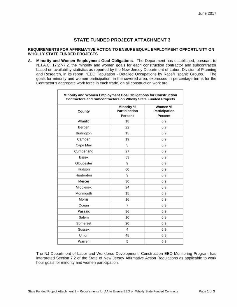
June 2017
State Funded Project Attachment 3 – Requirements for AA to Ensure EEO on Wholly State Funded Contracts Page 1 of 3
STATE FUNDED PROJECT ATTACHMENT 3
REQUIREMENTS FOR AFFIRMATIVE ACTION TO ENSURE EQUAL EMPLOYMENT OPPORTUNITY ON WHOLLY STATE FUNDED PROJECTS A. Minority and Women Employment Goal Obligations. The Department has established, pursuant to
N.J.A.C. 17:27-7.2, the minority and women goals for each construction contractor and subcontractor based on availability statistics as reported by the New Jersey Department of Labor, Division of Planning and Research, in its report, “EEO Tabulation - Detailed Occupations by Race/Hispanic Groups.” The goals for minority and women participation, in the covered area, expressed in percentage terms for the Contractor’s aggregate work force in each trade, on all construction work are:
Minority and Women Employment Goal Obligations for Construction Contractors and Subcontractors on Wholly State Funded Projects
County Minority %
Participation Women %
Participation Percent Percent
Atlantic 18 6.9
Bergen 22 6.9
Burlington 15 6.9
Camden 19 6.9
Cape May 5 6.9
Cumberland 27 6.9
Essex 53 6.9
Gloucester 9 6.9
Hudson 60 6.9
Hunterdon 3 6.9
Mercer 30 6.9
Middlesex 24 6.9
Monmouth 15 6.9
Morris 16 6.9
Ocean 7 6.9
Passaic 36 6.9
Salem 10 6.9
Somerset 20 6.9
Sussex 4 6.9
Union 45 6.9
Warren 5 6.9
The NJ Department of Labor and Workforce Development, Construction EEO Monitoring Program has interpreted Section 7.2 of the State of New Jersey Affirmative Action Regulations as applicable to work hour goals for minority and women participation.
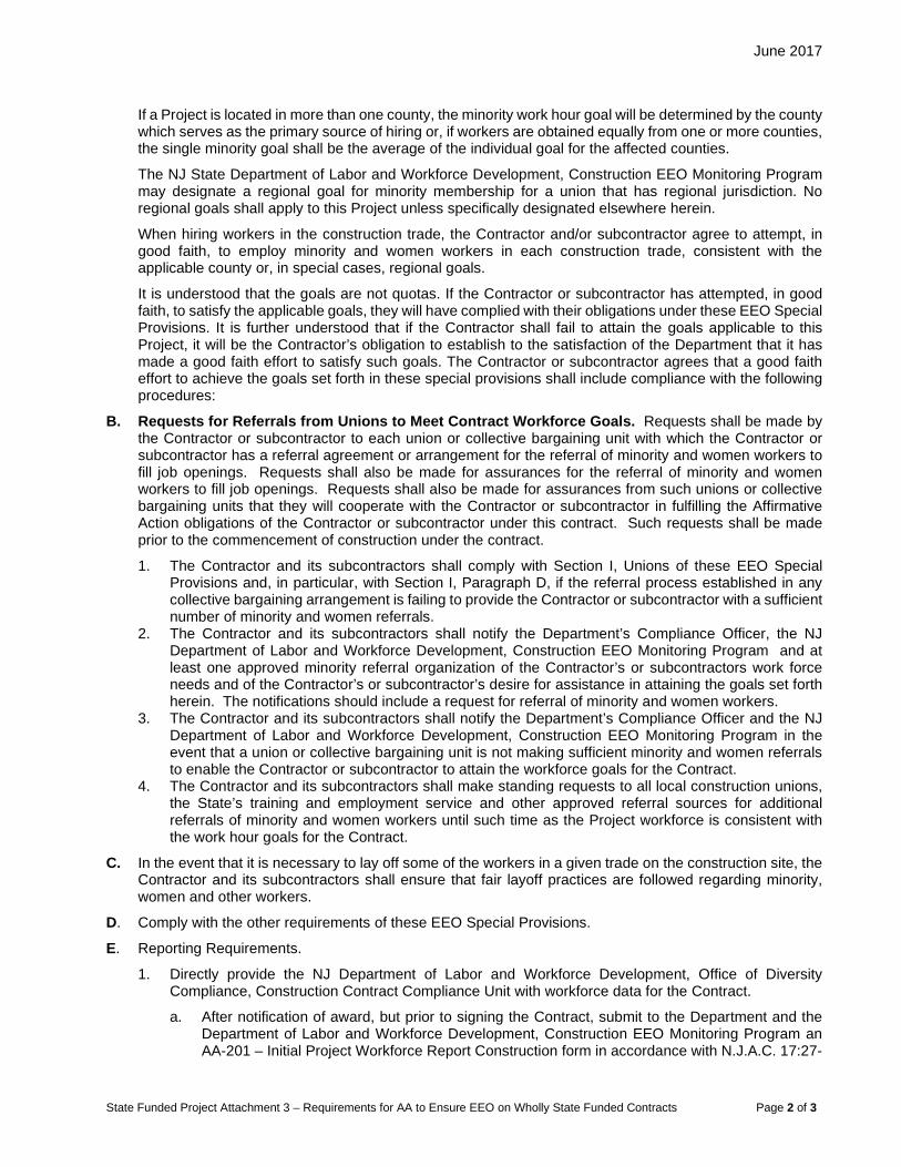
June 2017
State Funded Project Attachment 3 – Requirements for AA to Ensure EEO on Wholly State Funded Contracts Page 2 of 3
If a Project is located in more than one county, the minority work hour goal will be determined by the county which serves as the primary source of hiring or, if workers are obtained equally from one or more counties, the single minority goal shall be the average of the individual goal for the affected counties.
The NJ State Department of Labor and Workforce Development, Construction EEO Monitoring Program may designate a regional goal for minority membership for a union that has regional jurisdiction. No regional goals shall apply to this Project unless specifically designated elsewhere herein.
When hiring workers in the construction trade, the Contractor and/or subcontractor agree to attempt, in good faith, to employ minority and women workers in each construction trade, consistent with the applicable county or, in special cases, regional goals.
It is understood that the goals are not quotas. If the Contractor or subcontractor has attempted, in good faith, to satisfy the applicable goals, they will have complied with their obligations under these EEO Special Provisions. It is further understood that if the Contractor shall fail to attain the goals applicable to this Project, it will be the Contractor’s obligation to establish to the satisfaction of the Department that it has made a good faith effort to satisfy such goals. The Contractor or subcontractor agrees that a good faith effort to achieve the goals set forth in these special provisions shall include compliance with the following procedures:
B. Requests for Referrals from Unions to Meet Contract Workforce Goals. Requests shall be made by the Contractor or subcontractor to each union or collective bargaining unit with which the Contractor or subcontractor has a referral agreement or arrangement for the referral of minority and women workers to fill job openings. Requests shall also be made for assurances for the referral of minority and women workers to fill job openings. Requests shall also be made for assurances from such unions or collective bargaining units that they will cooperate with the Contractor or subcontractor in fulfilling the Affirmative Action obligations of the Contractor or subcontractor under this contract. Such requests shall be made prior to the commencement of construction under the contract.
1. The Contractor and its subcontractors shall comply with Section I, Unions of these EEO Special Provisions and, in particular, with Section I, Paragraph D, if the referral process established in any collective bargaining arrangement is failing to provide the Contractor or subcontractor with a sufficient number of minority and women referrals.
2. The Contractor and its subcontractors shall notify the Department’s Compliance Officer, the NJ Department of Labor and Workforce Development, Construction EEO Monitoring Program and at least one approved minority referral organization of the Contractor’s or subcontractors work force needs and of the Contractor’s or subcontractor’s desire for assistance in attaining the goals set forth herein. The notifications should include a request for referral of minority and women workers.
3. The Contractor and its subcontractors shall notify the Department’s Compliance Officer and the NJ Department of Labor and Workforce Development, Construction EEO Monitoring Program in the event that a union or collective bargaining unit is not making sufficient minority and women referrals to enable the Contractor or subcontractor to attain the workforce goals for the Contract.
4. The Contractor and its subcontractors shall make standing requests to all local construction unions, the State’s training and employment service and other approved referral sources for additional referrals of minority and women workers until such time as the Project workforce is consistent with the work hour goals for the Contract.
C. In the event that it is necessary to lay off some of the workers in a given trade on the construction site, the Contractor and its subcontractors shall ensure that fair layoff practices are followed regarding minority, women and other workers.
D. Comply with the other requirements of these EEO Special Provisions.
E. Reporting Requirements.
1. Directly provide the NJ Department of Labor and Workforce Development, Office of Diversity Compliance, Construction Contract Compliance Unit with workforce data for the Contract.
a. After notification of award, but prior to signing the Contract, submit to the Department and the Department of Labor and Workforce Development, Construction EEO Monitoring Program an AA-201 – Initial Project Workforce Report Construction form in accordance with N.J.A.C. 17:27-
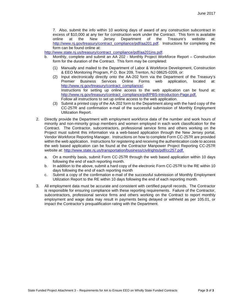
June 2017
State Funded Project Attachment 3 – Requirements for AA to Ensure EEO on Wholly State Funded Contracts Page 3 of 3
7. Also, submit the info within 10 working days of award of any construction subcontract in excess of $10,000 at any tier for construction work under the Contract. This form is available online at the New Jersey Department of the Treasure’s website at: http://www.nj.gov/treasury/contract_compliance/pdf/aa201.pdf. Instructions for completing the form can be found online at:
http://www.state.nj.us/treasury/contract_compliance/pdf/aa201ins.pdf. b. Monthly, complete and submit an AA 202 - Monthly Project Workforce Report – Construction
form for the duration of the Contract. This form may be completed:
(1) Manually and mailed to the Department of Labor & Workforce Development, Construction & EEO Monitoring Program, P.O. Box 209, Trenton, NJ 08625-0209, or:
(2) Input electronically directly onto the AA-202 form via the Department of the Treasury’s Premier Business Services Online Forms web application, located at: http://www.nj.gov/treasury/contract_compliance/. Instructions for setting up online access to the web application can be found at: http://www.nj.gov/treasury/contract_compliance/pdf/PBS-Introduction-Page.pdf. Follow all instructions to set up online access to the web application.
(3) Submit a printed copy of the AA-202 form to the Department along with the hard copy of the CC-257R and confirmation e-mail of the successful submission of Monthly Employment Utilization Report.
2. Directly provide the Department with employment workforce data of the number and work hours of minority and non-minority group members and women employed in each work classification for the Contract. The Contractor, subcontractors, professional service firms and others working on the Project must submit this information via a web-based application through the New Jersey portal, Vendor Workforce Reporting Manager. Instructions on how to complete Form CC-257R are provided within the web application. Instructions for registering and receiving the authentication code to access the web based application can be found at the Contractor Manpower Project Reporting CC-257R website at: http://www.state.nj.us/transportation/business/civilrights/pdf/cc257.pdf.
a. On a monthly basis, submit Form CC-257R through the web based application within 10 days following the end of each reporting month.
b. In addition to the above, submit a hard copy of the electronic Form CC-257R to the RE within 10 days following the end of each reporting month
c. Submit a copy of the confirmation e-mail of the successful submission of Monthly Employment Utilization Report to the RE within 10 days following the end of each reporting month.
3. All employment data must be accurate and consistent with certified payroll records. The Contractor is responsible for ensuring compliance with these reporting requirements. Failure of the Contractor, subcontractors, professional service firms and others working on the Contract to report monthly employment and wage data may result in payments being delayed or withheld as per 105.01, or impact the Contractor’s prequalification rating with the Department.
June 2017
State Funded Project Attachment 4 – Investigating, Reporting & Resolving Employment Discrimination & Sexual Harassment Complaints Page 1 of 1
STATE FUNDED PROJECT ATTACHMENT 4
INVESTIGATING, REPORTING AND RESOLVING EMPLOYMENT DISCRIMINATION AND SEXUAL HARASSMENT COMPLAINTS ON WHOLLY STATE FUNDED PROJECTS The Contractor hereby agrees to the following requirements in order to implement fully the nondiscrimination provisions of the Supplemental Specifications:
The Contractor agrees that in instances when it receives from any person working on the Project site a verbal or written complaint of employment discrimination, prohibited under N.J.S.A. 10:5-1 et seq. 10:2-1 et seq., 42 U.S.C. 2000 (d) et seq., 42 U.S.C. 2000(e) et seq. and Executive Order 11246, it shall take the following actions:
A. Within one (1) working day commence an investigation of the complaint, which will include but not be limited to interviewing the complainant, the respondent, and all possible witnesses to the alleged act or acts of discrimination or sexual harassment.
B. Prepare and keep for its use and file a detailed written investigation report which includes the following information:
1. Investigatory activities and findings. 2. Dates and parties involved and activities involved in resolving the complaint. 3. Resolution and corrective action taken if discrimination or sexual harassment is found to have taken
place. 4. A signed copy of resolution of complaint by complainant and Contractor.
(In addition to keeping in its files the above-noted detailed written investigative report, the Contractor shall keep for possible future review by the Department, all other records, including, but not limited to, interview memos and statements.)
C. Upon the request of the Department, provides to the Department within ten (10) calendar days a copy of its detailed written investigative report and all other records on the complaint investigation and resolution.
D. Take appropriate disciplinary actions against any Contractor employee, official or agent who has committed acts of discrimination or sexual harassment against any Contractor employee or person working on the Project. If the person committing the discrimination is a subcontractor employee, then the Contractor is required to attempt to effectuate corrective and/or disciplinary action by the subcontractor in order to establish compliance with the Contract.
E. Take appropriate disciplinary action against any Contractor employee, official or agent who retaliates, coerces or intimidates any complainant and/or person who provides information or assistance to any investigation of complaints of discrimination or sexual harassment. If the person retaliating, coercing or intimidating a complainant or other person assisting in an investigation is a subcontractor’s employee, then the Contractor is required to attempt to effectuate corrective and/or disciplinary action taken by the subcontractor in order to establish compliance with the Contract.
F. Ensure to the maximum extent possible that the privacy interests of all persons who give confidential information in aid of the Contractor’s employment discrimination investigation are protected.
G. In conjunction with the above requirements, the Contractor herein agrees to develop and post a written sexual harassment policy for its workforce.
H. The Contractor also agrees that its failure to comply with the above requirements may be cause for the Department to institute against the Contractor any and all enforcement proceedings and/or sanctions authorized by the Contract or by State and/or Federal law.
April 2019
State Funded Project Attachment 5 - Payroll Requirements for Wholly State Funded Projects Page 1 of 1
STATE FUNDED PROJECT ATTACHMENT 5
PAYROLL REQUIREMENTS FOR WHOLLY STATE FUNDED PROJECTS A. Payroll Reports. Each Contractor and subcontractor shall furnish the RE with payroll reports for each
week of contract work. Such reports shall be submitted within 10 days of the date of payment covered thereby and shall contain the following information:
1. Each employee’s full name and address of each such employee. 2. The ethnicity and gender of each employee. 3. Each employee’s specific work classification (s). 4. Entries indicating each employee’s basis hourly wage rate(s) and, where applicable, the overtime
hourly wage rate(s). Any fringe benefits paid to approved plans, funds or programs on behalf of the employee must be indicated. Any fringe benefits paid to the employee in cash must be indicated.
5. Each employee’s daily and weekly hours worked in each classification, including actual overtime hours worked (not adjusted).
6. Each employee’s gross wage. 7. The itemized deductions made. 8. The net wages paid.
B. Statement of Wages. Each Contractor or subcontractor shall furnish a statement each week to the RE with respect to the wages paid each of its employees engaged in contract work covered by the New Jersey Prevailing Wage Act during the preceding weekly payroll period. The statement shall be executed by the Contractor or subcontractor or by an authorized officer or employee of the Contractor or subcontractors who supervises the payment of wages. Contractors and subcontractors must use the certification set forth on NJ Department of Labor Payroll Certification for Public Works Project (R-08-12-08), or any form with identical wording.
C. Maintaining Records. Contractor and subcontractor shall maintain complete social security numbers and home address for employees. Government agencies are entitled to request or review all relevant payroll information, including social security numbers and addresses of employees. Contractors and subcontractors are required to provide such information upon request.
D. Lack of Compliance. Failure of the Contractor or subcontractor to comply with the payroll requirements may result in payment being delayed or withheld as specified in Section 105, default as specified in Section 108 or termination of the Contract as specified in Section 108.
E. Diane B. Allen Equal Pay Act, N.J.S.A. 34:11-56.14b. Pursuant to the DIANE B. ALLEN EQUAL PAY ACT, N.J.S.A. 34:11-56.14.b., the Contractor shall provide to the Commissioner of the New Jersey Department of Labor and Workforce Development, through certified payroll records required pursuant to P.L.1963, c.150 (C.34:11-56.25 et seq.), information regarding the gender, race, job title, occupational category, and rate of total compensation of every employee of the employer employed in the State in connection with the Contract. The Contractor shall provide the Commissioner, throughout the duration of the Contract, with an update to the information whenever payroll records are required to be submitted pursuant to P.L.1963, c.150 (C.34:11-56.25 et seq.). Completed forms should be emailed to: [email protected]. If online submission is not possible, the form should be mailed to: Equal Pay Act, New Jersey Department of Labor and Workforce Development, P.O. Box 110, Trenton, NJ 08625-110.
Information regarding the Diane B. Allen Equal Pay Act and its requirements may be obtained from the New Jersey Department of Labor and Workforce Development (LWD) website at: https://nj.gov/labor/equalpay/equalpay.html
LWD forms may be obtained from the online web site at: https://nj.gov/labor/forms_pdfs/equalpayact/MW-562withoutfein.pdf
June 2017
State Funded Project Attachment 6 – ADA Act State Funded Projects Page 1 of 1
STATE FUNDED PROJECT ATTACHMENT 6
AMERICANS WITH DISABILITIES ACT REQUIREMENTS FOR WHOLLY STATE FUNDED PROJECTS
Equal Opportunity for Individuals with Disabilities. The CONTRACTOR and the STATE do hereby agree that the provisions of Title II of the American With Disabilities Act of 1990 (the “ACT”) (42 U.S.C. Section 12101 et seq.), which prohibits discrimination on the basis of disability by public entities in all services, programs, and activities provided or made available by public entities, and the rules and regulations promulgated pursuant thereunto, are made a part of this contract. In providing any aid, benefit, or service on behalf of the STATE pursuant to this contract, the CONTRACTOR, agrees that the performance shall be in strict compliance with the Act. In the event that the CONTRACTOR, its agents, servants, employees, or subcontractors violate or are alleged to have violated the Act during the performance of this contract, the CONTRACTOR shall defend the STATE in any action or administrative proceeding commenced pursuant to this Act. The CONTRACTOR shall indemnify, protect, and save harmless the STATE, its agents, servants, and employees from and against any and all suits, claims, losses, demands, or damages of whatever kind or nature arising out of or claimed to arise out of the alleged violation. The CONTRACTOR shall, at its own expense, appear, defend, and pay any and all charges for legal services and all costs and other expenses arising from such action or administrative proceeding or incurred in connection therewith. In any and all complaints brought pursuant to the STATE’S grievance procedure, the CONTRACTOR agrees to abide by any decision of the STATE which is rendered pursuant to said grievance procedure. If any action or administrative proceeding results in an award of damages against the STATE or if the STATE incurs any expense to cure a violation of the ADA which has been brought pursuant to its grievance procedure, the CONTRACTOR shall satisfy and discharge the same at its own expense.
The STATE shall, as soon as practicable after a claim has been made against it, give written notice thereof to the CONTRACTOR along with full and complete particulars of the claim. If any action or administrative proceeding is brought against the STATE or any of its agents, servants, and employees, the STATE shall expeditiously forward or have forwarded to the CONTRACTOR every demand, complaint, notice, summons, pleading, or other process received by the STATE or its representatives.
It is expressly agreed and understood that any approval by the STATE of the services provided by the CONTRACTOR pursuant to this contract will not relieve the CONTRACTOR of the obligation to comply with the Act and to defend, indemnify, protect, and save harmless the STATE pursuant to this paragraph.
It is further agreed and understood that the STATE assumes no obligation to indemnify or save harmless the CONTRACTOR, its agents, servants, employees and subcontractors for any claim which may arise out of their performance of this Agreement. Furthermore, the CONTRACTOR expressly understands and agrees that the provisions of this indemnification clause shall in no way limit the CONTRACTOR’S obligations assumed in this Agreement, nor shall they be construed to relieve the CONTRACTOR from any liability, nor preclude the STATE from taking any other actions available to it under any other provisions of this Agreement or otherwise at law.

ATTACHMENT 7
RAILROAD ATTACHMENTS
PROJECT SPECIFIC ATTACHMENT 1
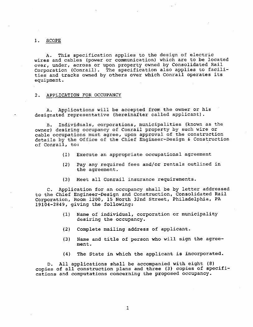
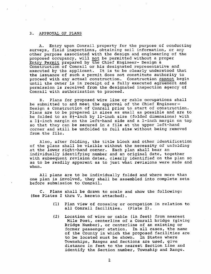
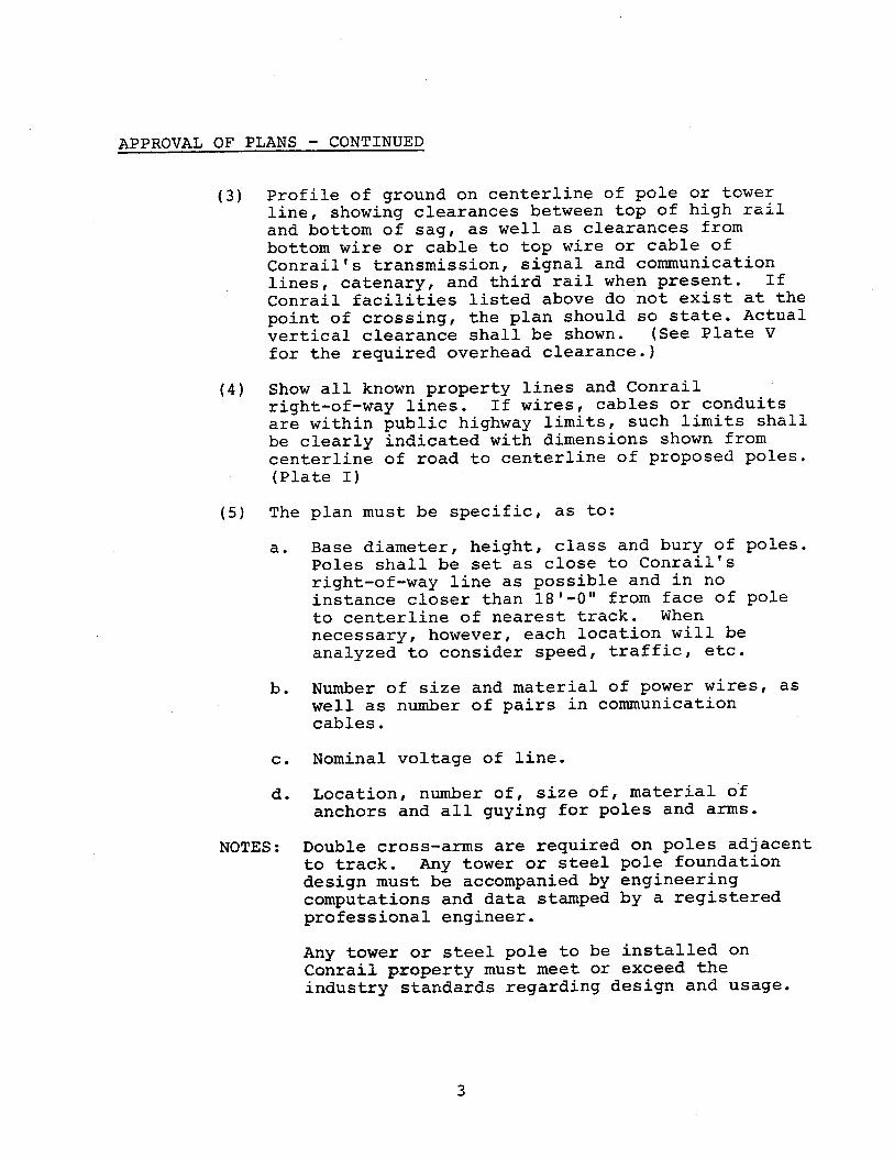
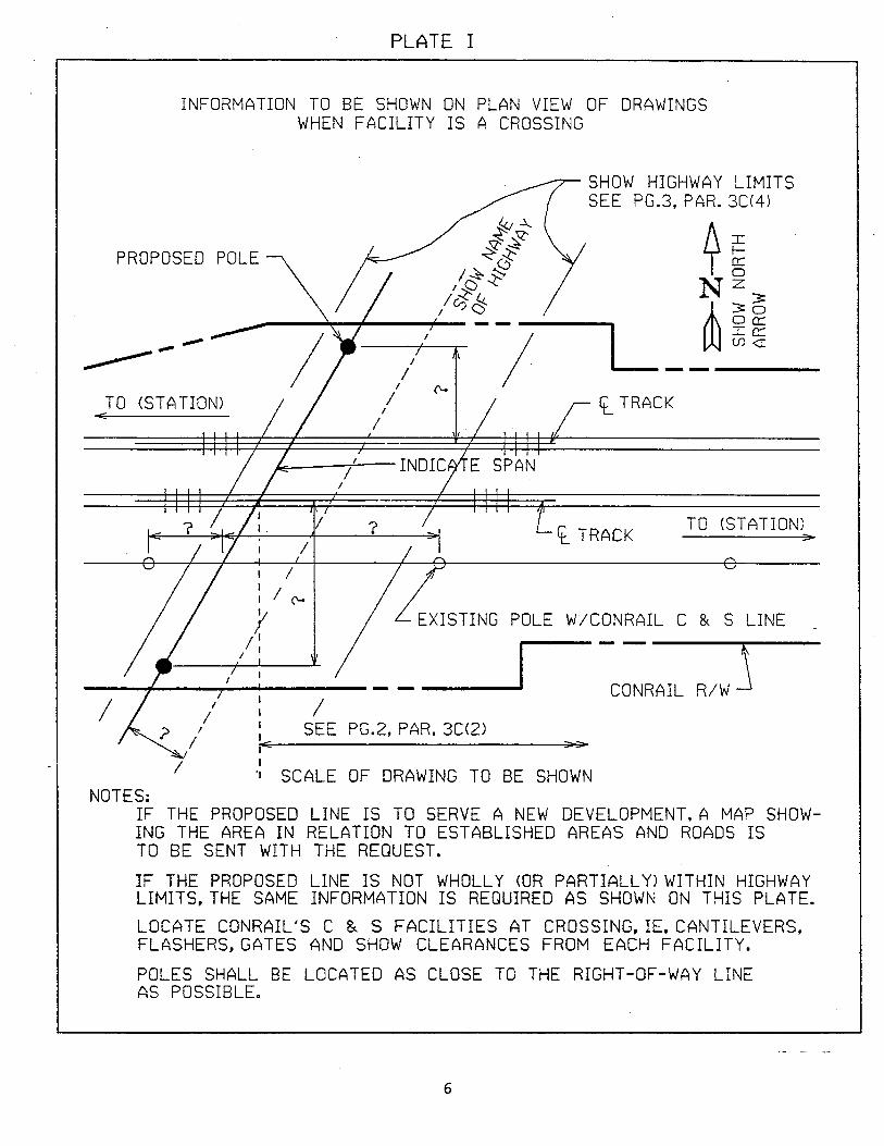
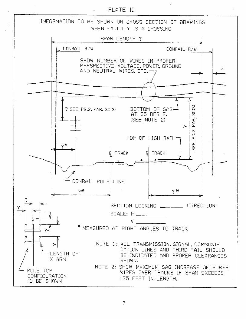
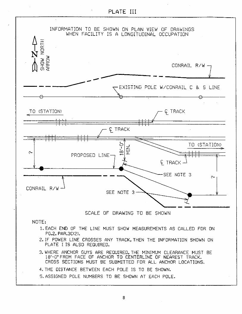
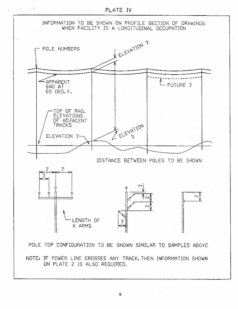
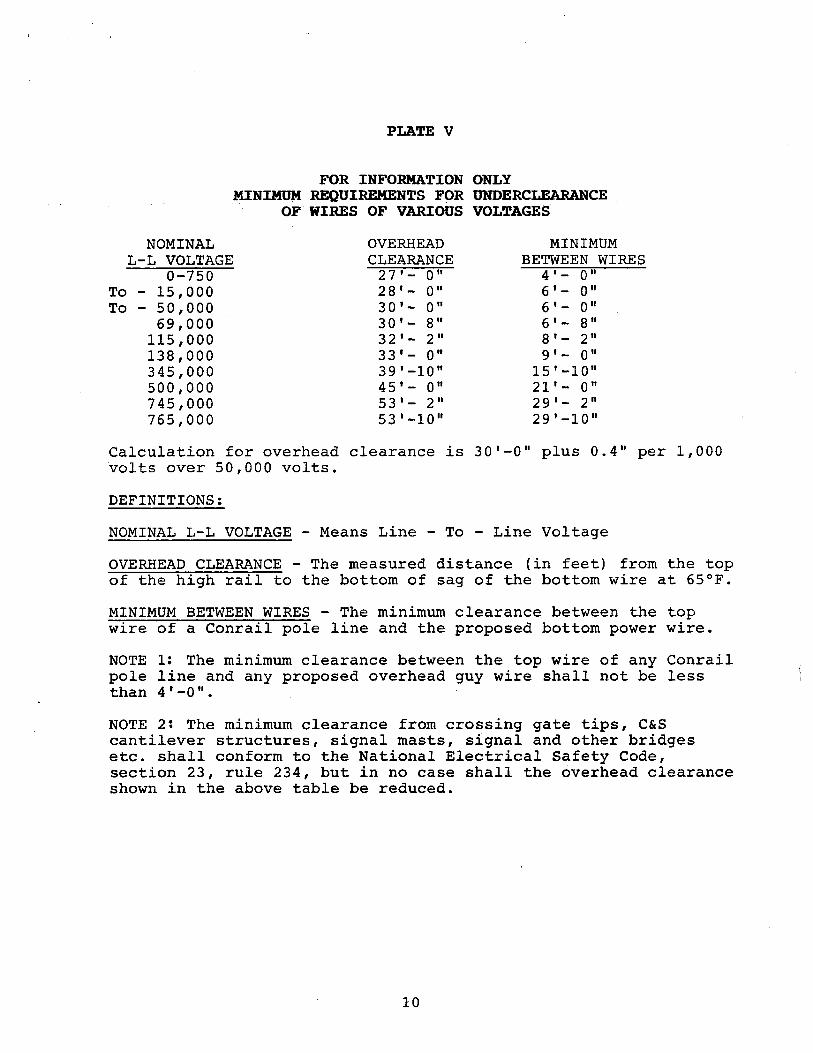
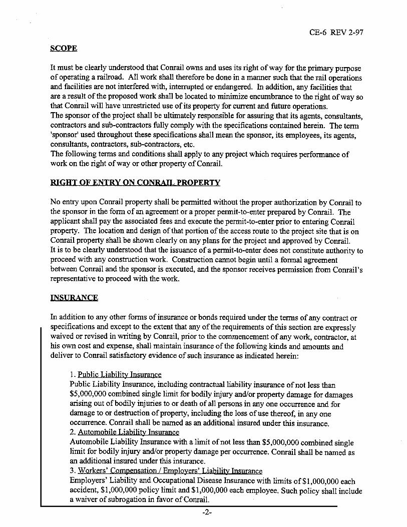
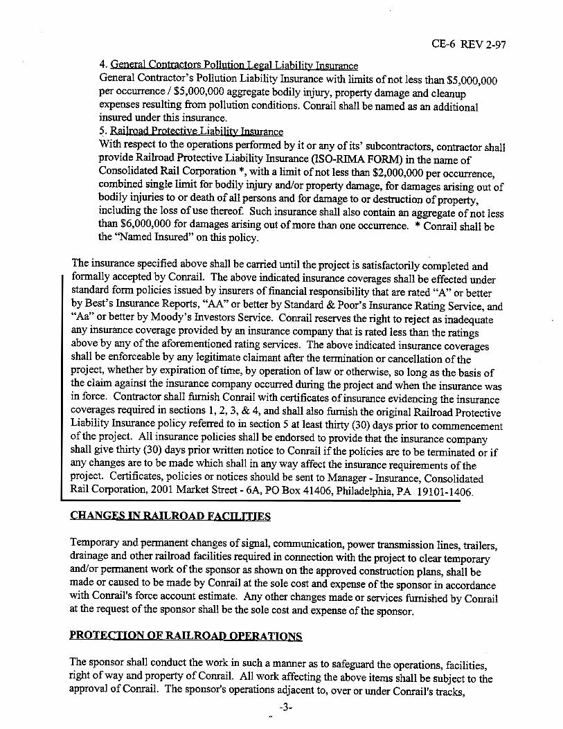
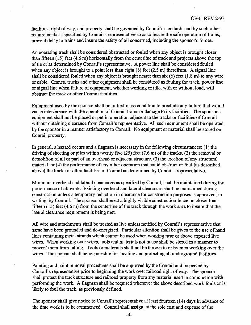

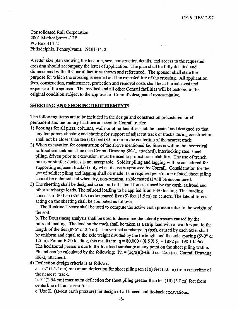
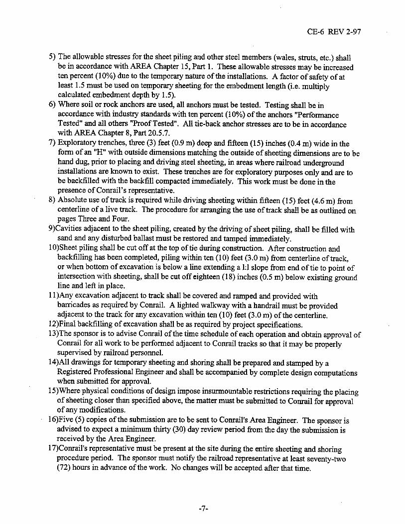
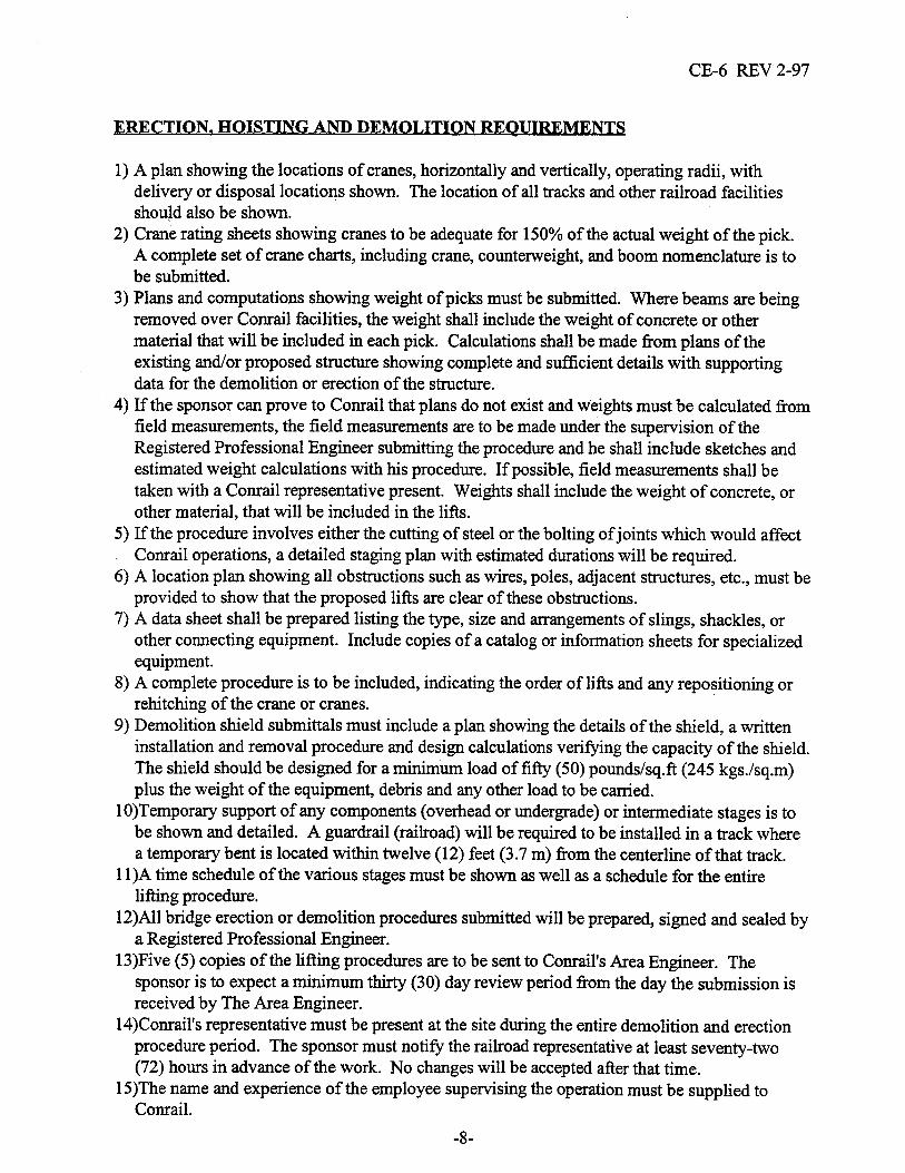
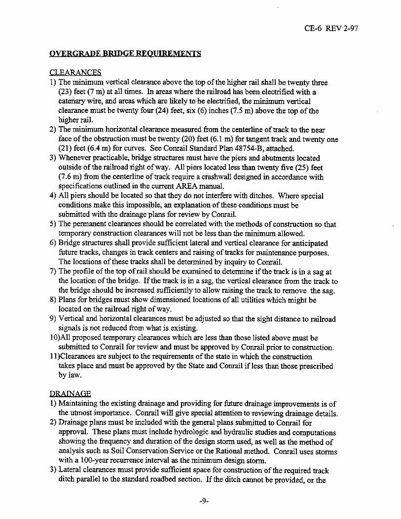
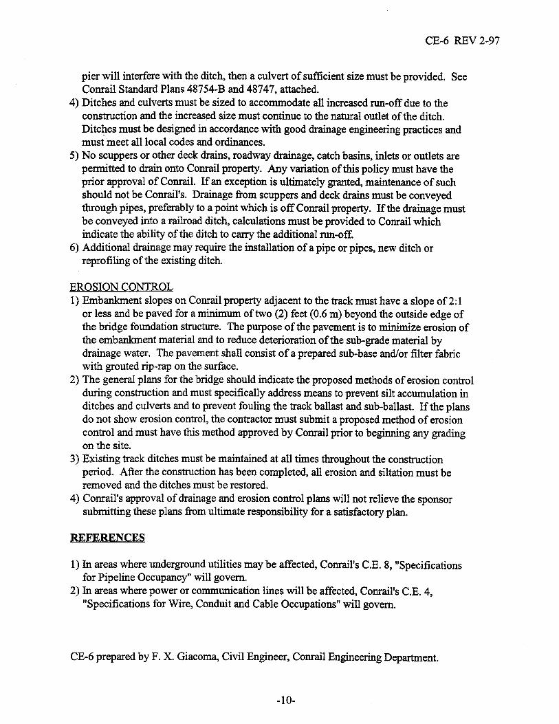
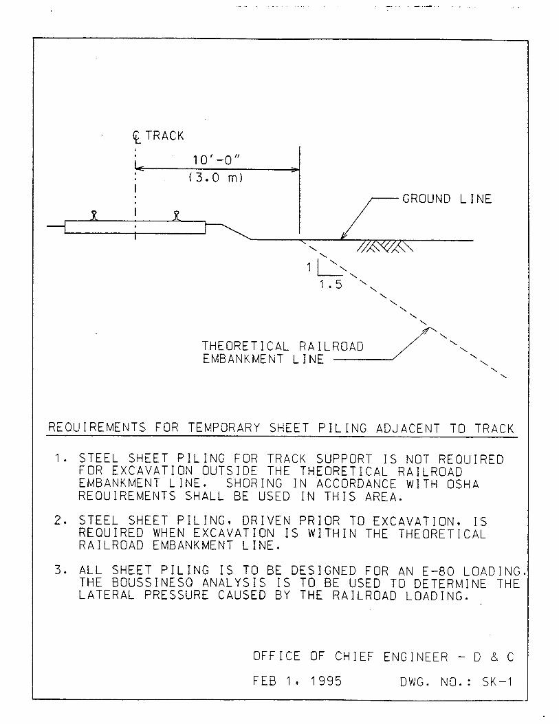

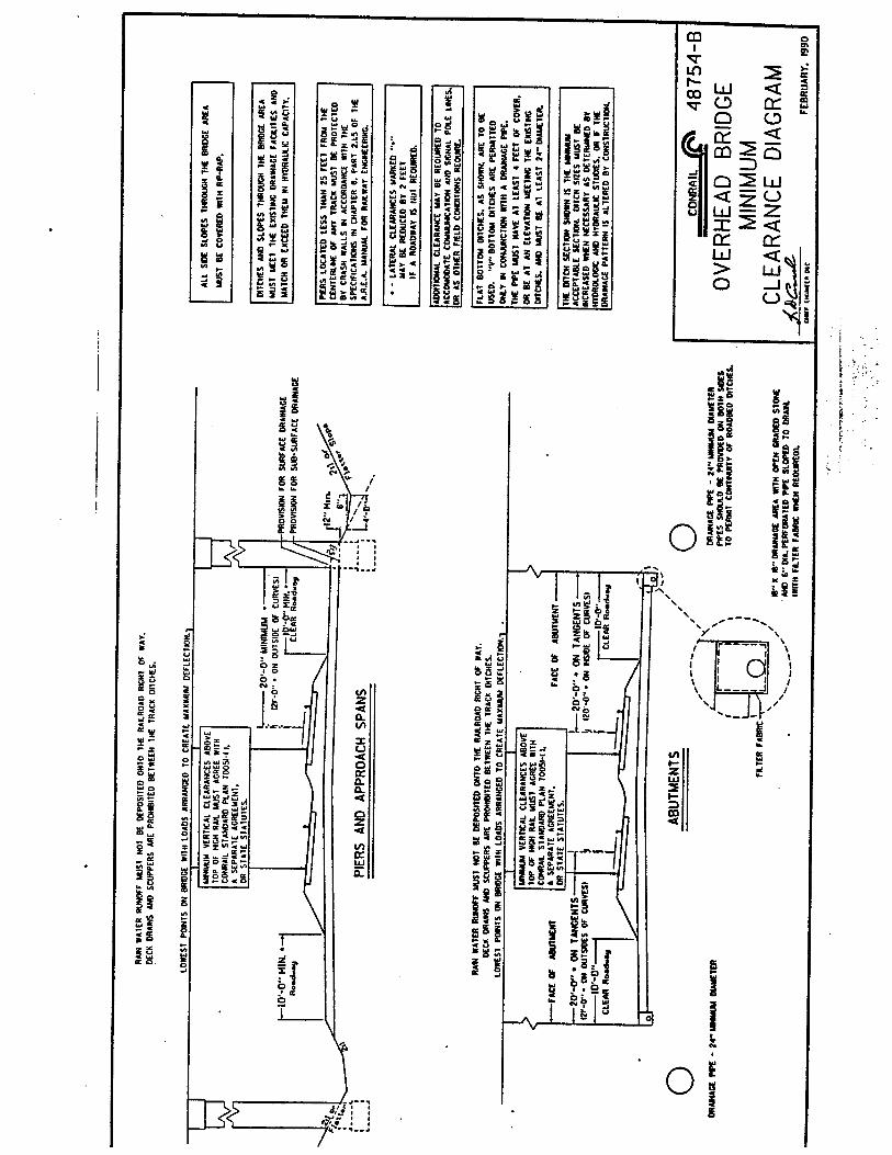
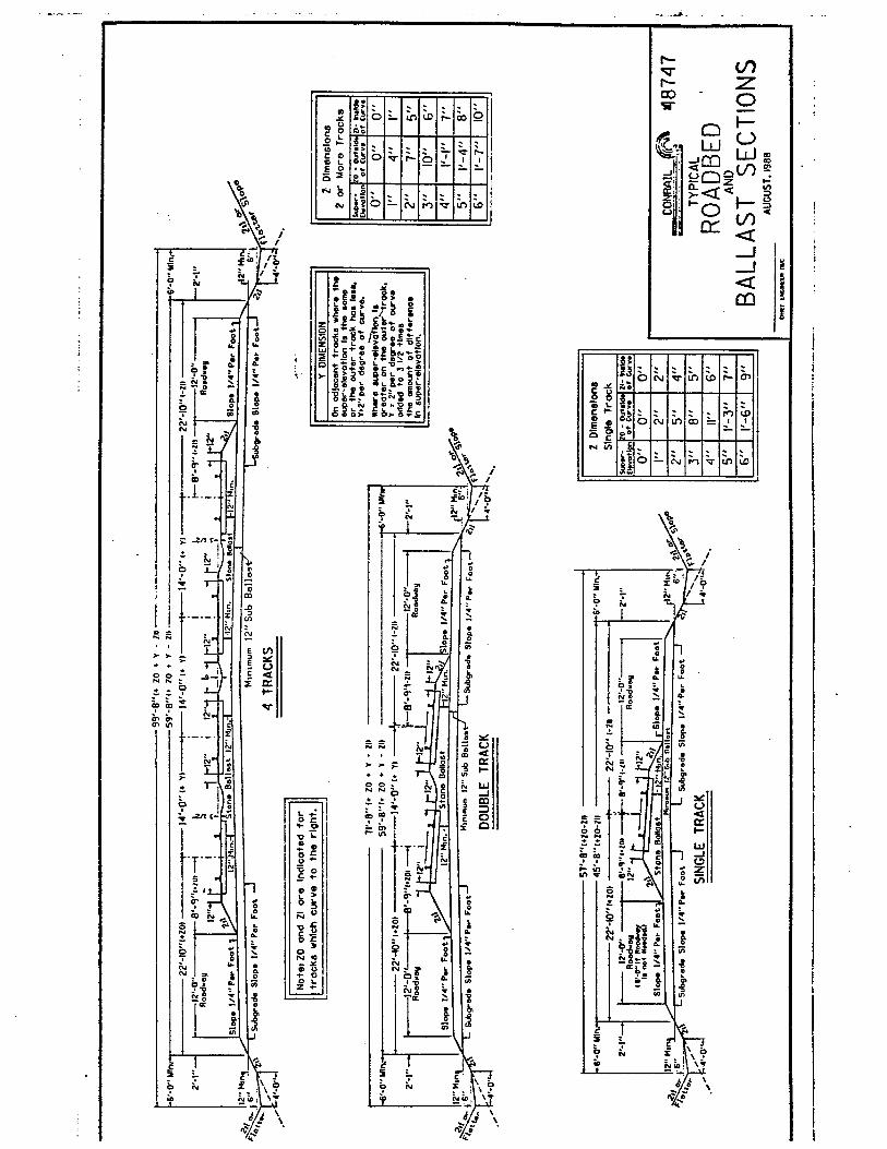
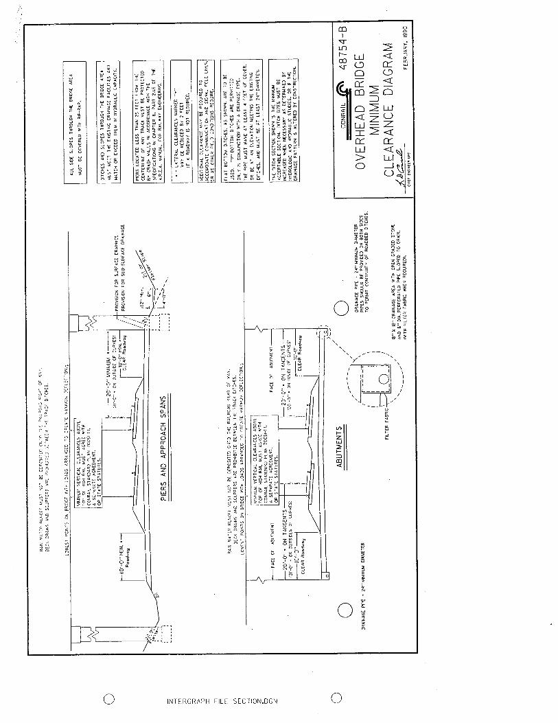
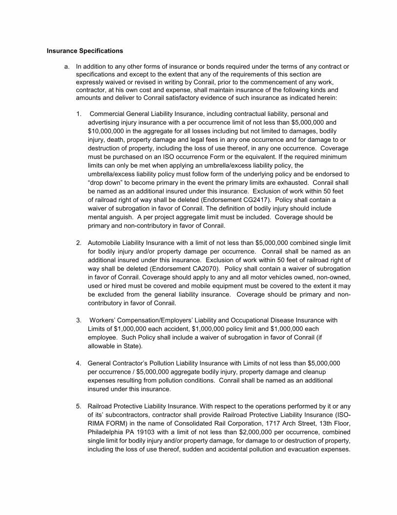
Insurance Specifications
a. In addition to any other forms of insurance or bonds required under the terms of any contract or specifications and except to the extent that any of the requirements of this section are expressly waived or revised in writing by Conrail, prior to the commencement of any work, contractor, at his own cost and expense, shall maintain insurance of the following kinds and amounts and deliver to Conrail satisfactory evidence of such insurance as indicated herein:
1. Commercial General Liability Insurance, including contractual liability, personal and
advertising injury insurance with a per occurrence limit of not less than $5,000,000 and $10,000,000 in the aggregate for all losses including but not limited to damages, bodily injury, death, property damage and legal fees in any one occurrence and for damage to or destruction of property, including the loss of use thereof, in any one occurrence. Coverage must be purchased on an ISO occurrence Form or the equivalent. If the required minimum limits can only be met when applying an umbrella/excess liability policy, the umbrella/excess liability policy must follow form of the underlying policy and be endorsed to “drop down” to become primary in the event the primary limits are exhausted. Conrail shall be named as an additional insured under this insurance. Exclusion of work within 50 feet of railroad right of way shall be deleted (Endorsement CG2417). Policy shall contain a waiver of subrogation in favor of Conrail. The definition of bodily injury should include mental anguish. A per project aggregate limit must be included. Coverage should be primary and non-contributory in favor of Conrail.
2. Automobile Liability Insurance with a limit of not less than $5,000,000 combined single limit for bodily injury and/or property damage per occurrence. Conrail shall be named as an additional insured under this insurance. Exclusion of work within 50 feet of railroad right of way shall be deleted (Endorsement CA2070). Policy shall contain a waiver of subrogation in favor of Conrail. Coverage should apply to any and all motor vehicles owned, non-owned, used or hired must be covered and mobile equipment must be covered to the extent it may be excluded from the general liability insurance. Coverage should be primary and non-contributory in favor of Conrail.
3. Workers’ Compensation/Employers’ Liability and Occupational Disease Insurance with Limits of $1,000,000 each accident, $1,000,000 policy limit and $1,000,000 each employee. Such Policy shall include a waiver of subrogation in favor of Conrail (if allowable in State).
4. General Contractor’s Pollution Liability Insurance with Limits of not less than $5,000,000 per occurrence / $5,000,000 aggregate bodily injury, property damage and cleanup expenses resulting from pollution conditions. Conrail shall be named as an additional insured under this insurance.
5. Railroad Protective Liability Insurance. With respect to the operations performed by it or any
of its’ subcontractors, contractor shall provide Railroad Protective Liability Insurance (ISO-RIMA FORM) in the name of Consolidated Rail Corporation, 1717 Arch Street, 13th Floor, Philadelphia PA 19103 with a limit of not less than $2,000,000 per occurrence, combined single limit for bodily injury and/or property damage, for damage to or destruction of property, including the loss of use thereof, sudden and accidental pollution and evacuation expenses.
Such insurance shall also contain an aggregate of not less than $6,000,000 for damages arising out of more than one occurrence. Conrail shall be the Named Insured on the policy.
b. The insurance specified above shall be carried until the project is satisfactorily completed and formally accepted by Conrail. The above indicated insurance coverages shall be effected under standard form policies issued by insurers of financial responsibility that are rated “A” or better by Best’s Insurance Reports, “AA” or better by Standard & Poor’s Insurance Rating Service and “Aa” or better by Moody’s Investors Service. Conrail reserves the right to reject as inadequate any insurance coverage provided by an insurance company that is rated less than the ratings above by any of the aforementioned rating services. The above indicated insurance coverages shall be enforceable by any legitimate claimant after the termination or cancellation of the project, whether by expiration of time, by operation of law or otherwise, so long as the basis of the claim against the insurance company occurred during the project and when the insurance was in force. Contractor shall furnish Conrail with certificates of insurance evidencing the insurance coverages in sections 1, 2, 3 & 4, and shall also furnish the original Railroad Protective Liability Insurance policy referred to in section 5 at least fourteen (14) days prior to commencement of the project. Certificates shall reference Conrail Project Number assigned to specific project. All hazards to be covered shall include the so-called “XCU” coverage for explosion, collapse, and damage where work is to be done over or under Conrail property. Policies shall not contain any punitive damages exclusion. All insurance policies shall be endorsed to provide that the insurance company shall give thirty (30) days prior written notice to Conrail if the policies are to be terminated or if any changes are to be made which shall in any way affect the insurance requirements of the project. Certificates, policies or notices should be sent to Director – Design and Construction, Consolidated Rail Corporation, 1000 Howard Blvd, 4th Floor, Mount Laurel, NJ 08054.
c. Separation of insureds. All policies must contain a separation of insureds provision except
workers compensation. Separation of insureds must be indicated on the certificate of insurance.
d. Self-Insurance. Contractor is not allowed to self-insure without the prior written consent of Conrail. If granted by Conrail, any deductible, self-insured retention or other financial responsibility for claims must be covered directly by contractors in lieu of insurance. Any and all Conrail liabilities that would otherwise in accordance with the provisions of the Agreement, be covered by contractor’s insurance will be covered as if contractor elected not to include a deductible, self-insured retention or other financial responsibility for claims.
e. Independent Associates, Consultants and Subcontractors. If any portion of the services are to
be subcontracted by contractor, contractor must require that the independent associates consultant and/or subcontractor provide and maintain the insurance coverages set forth herein, naming Conrail as an additional insured and requiring that the independent associate, consultant, and/or subcontractor release, defend and indemnify Conrail to the same extent and under the same terms and conditions as contractor is required to release, defend and indemnify Conrail herein.
f. No Limits: The fact that insurance (including without limitation, self-insurance) is obtained by
contractor will not be deemed to release or diminish the liability of contractor including, without limitation, liability under the indemnity provisions of the agreement. Damages recoverable by Conrail will not be limited by the amount of the required insurance.

g. Certificates shall show the location of the project, description of work and Conrail Project Number.
h. Certificates, policies or notices are to be sent to Conrail’s Project Engineer identified when the executed License or Agreement is returned to the sponsor.
PROJECT SPECIFIC ATTACHMENT 3
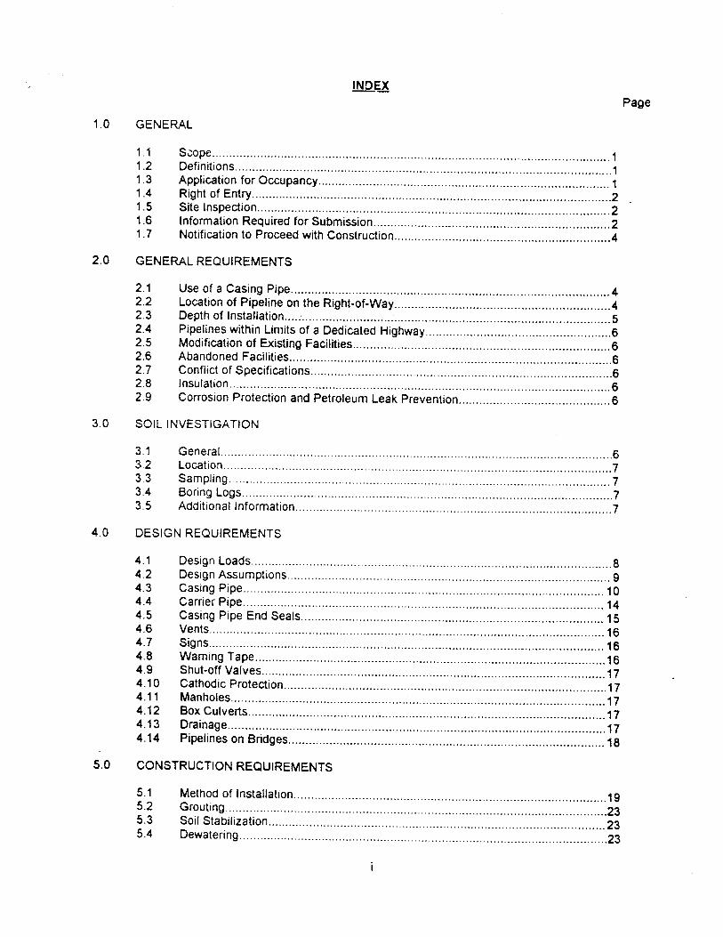
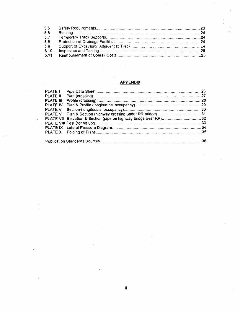
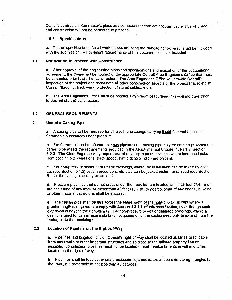
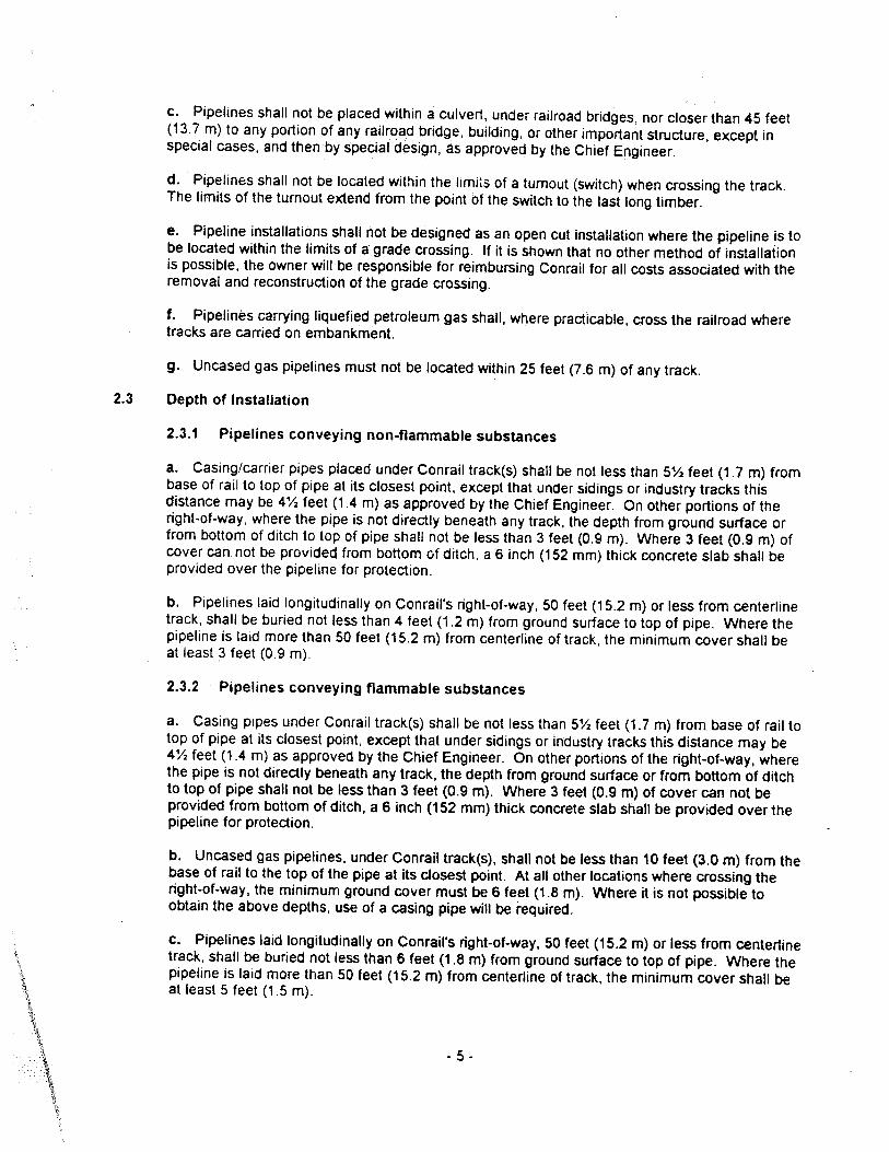
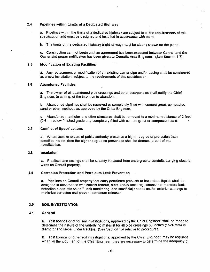
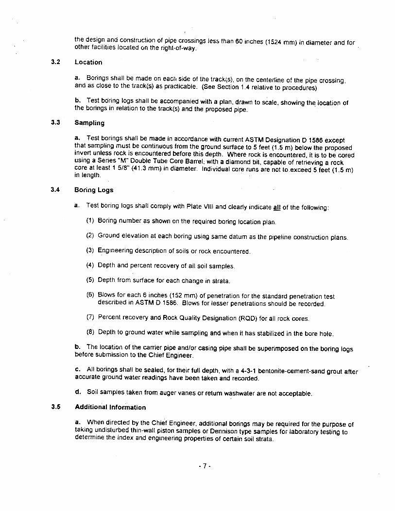
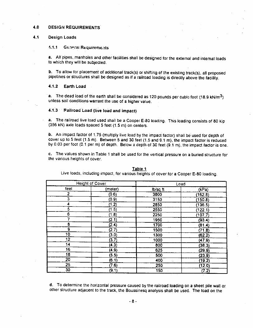
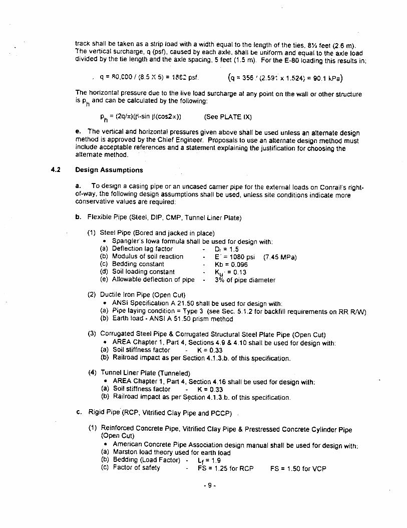
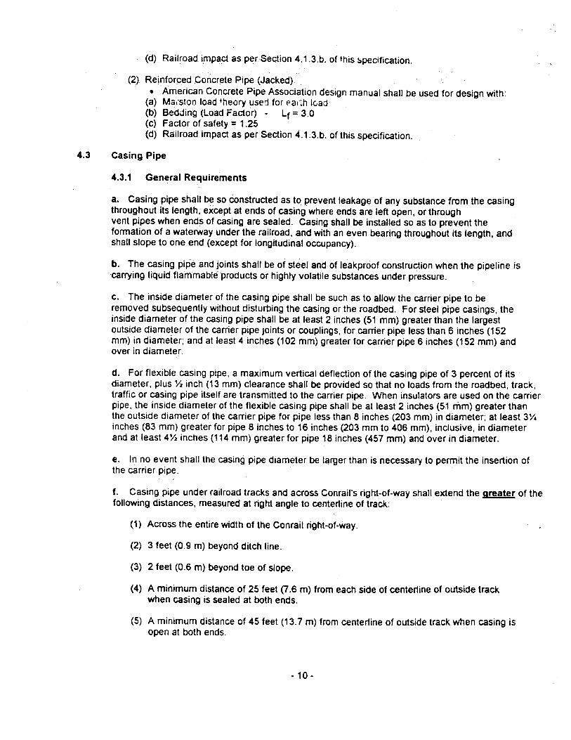
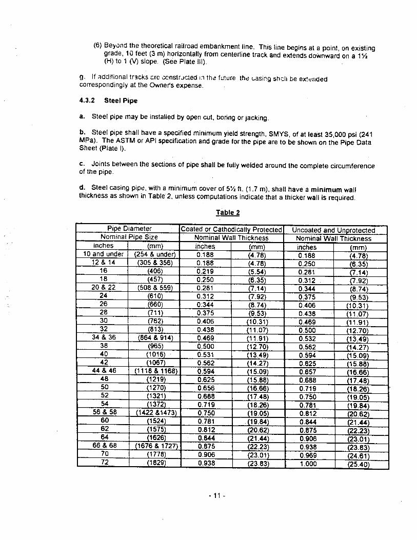
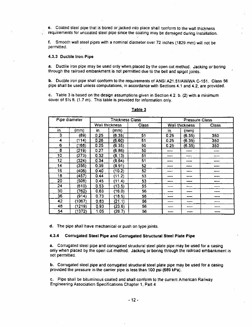
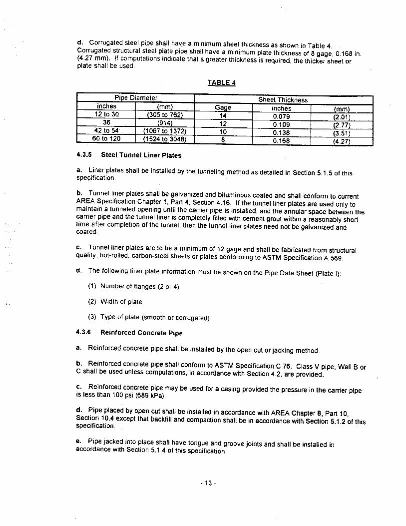
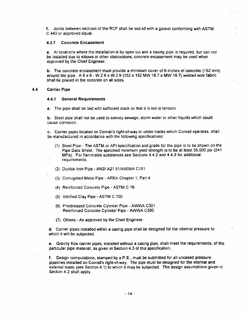
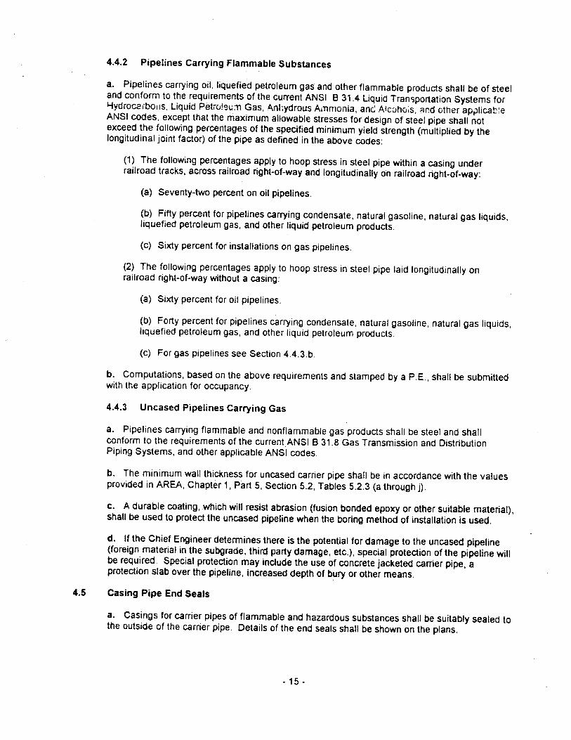
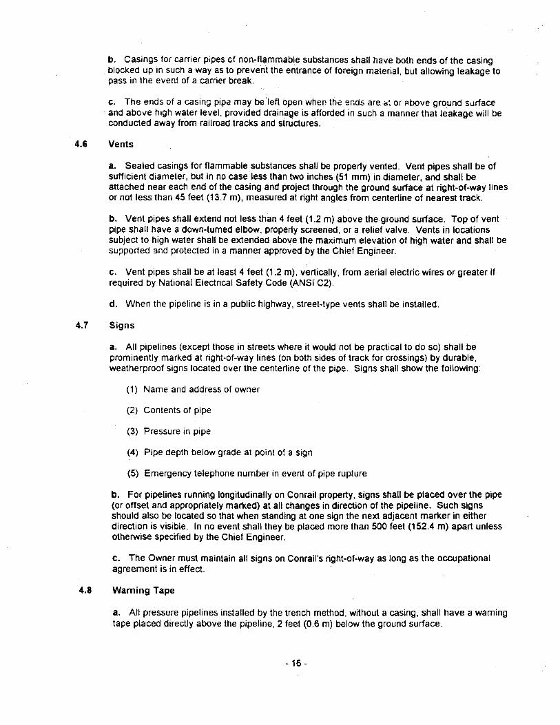
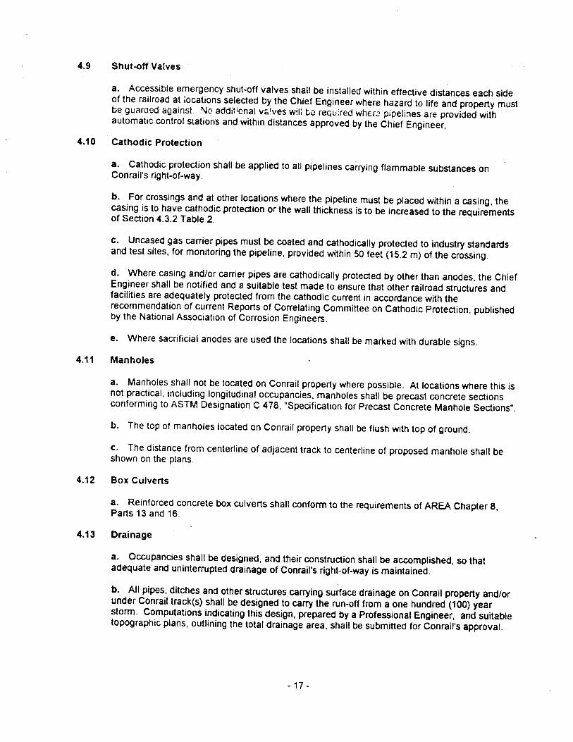
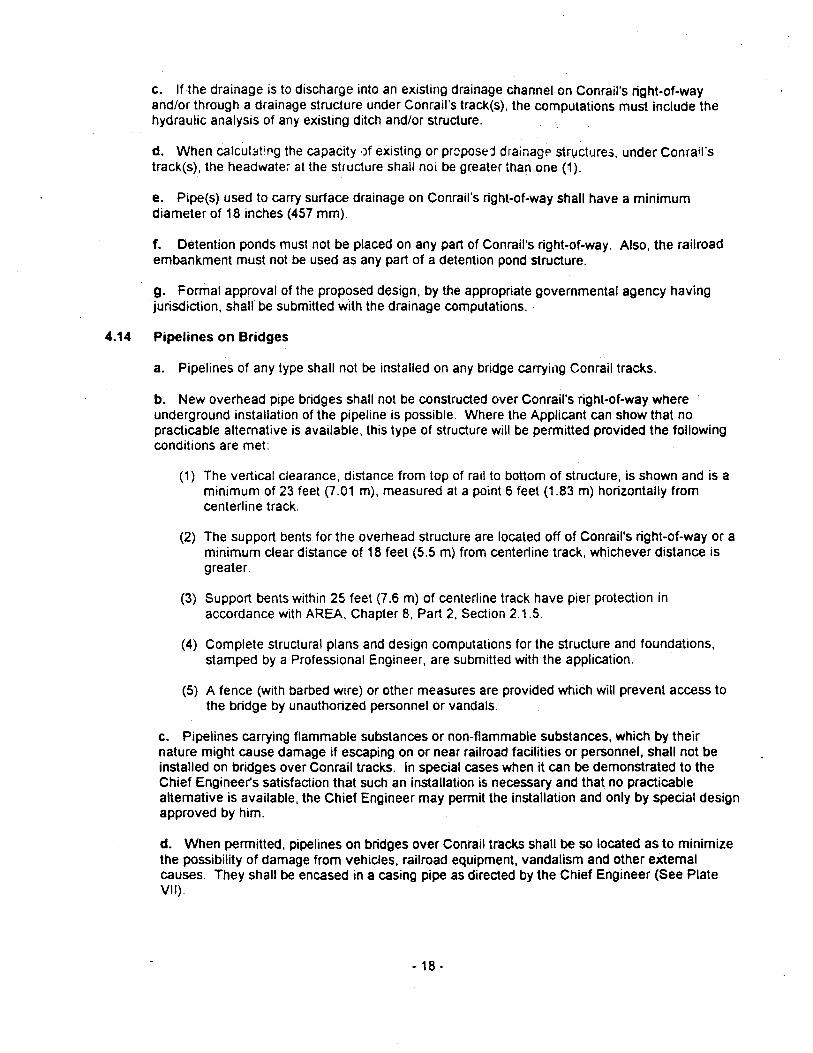
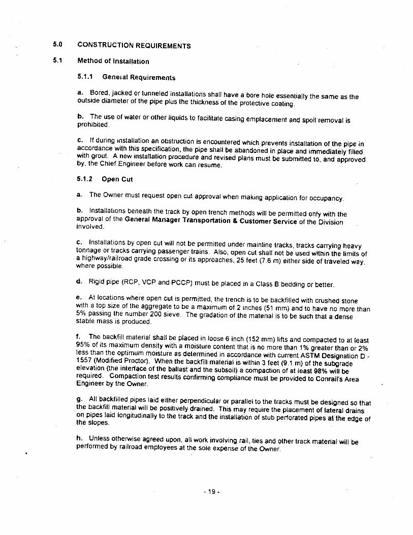
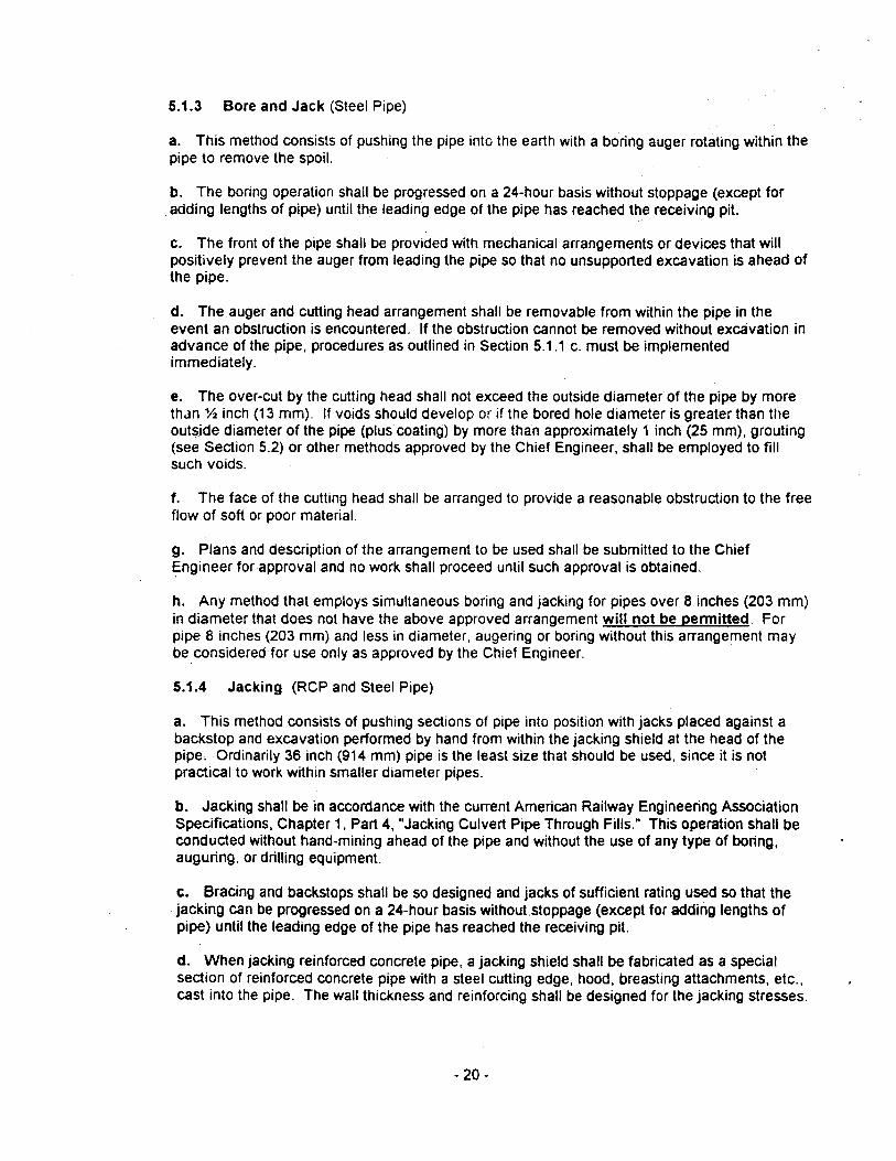
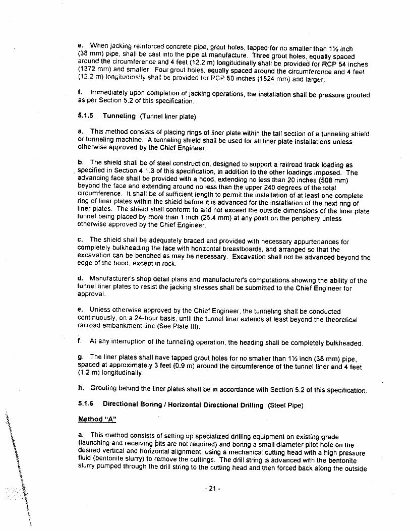
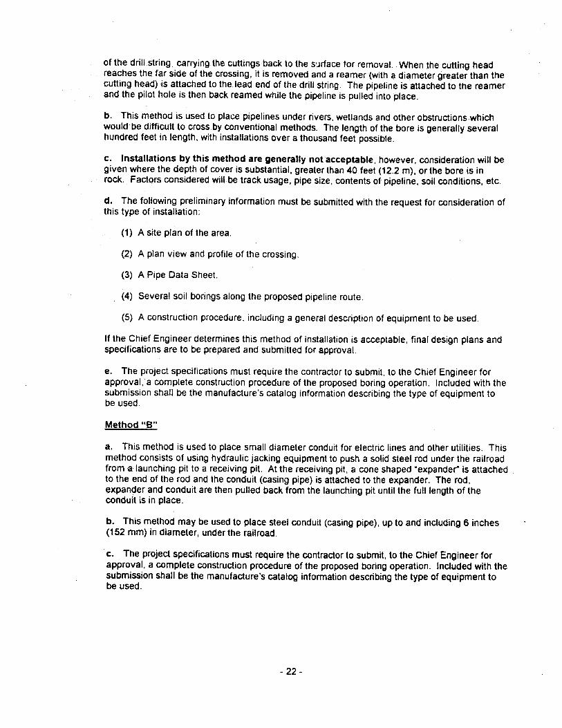
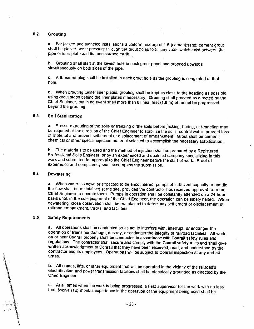
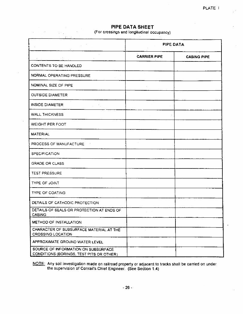
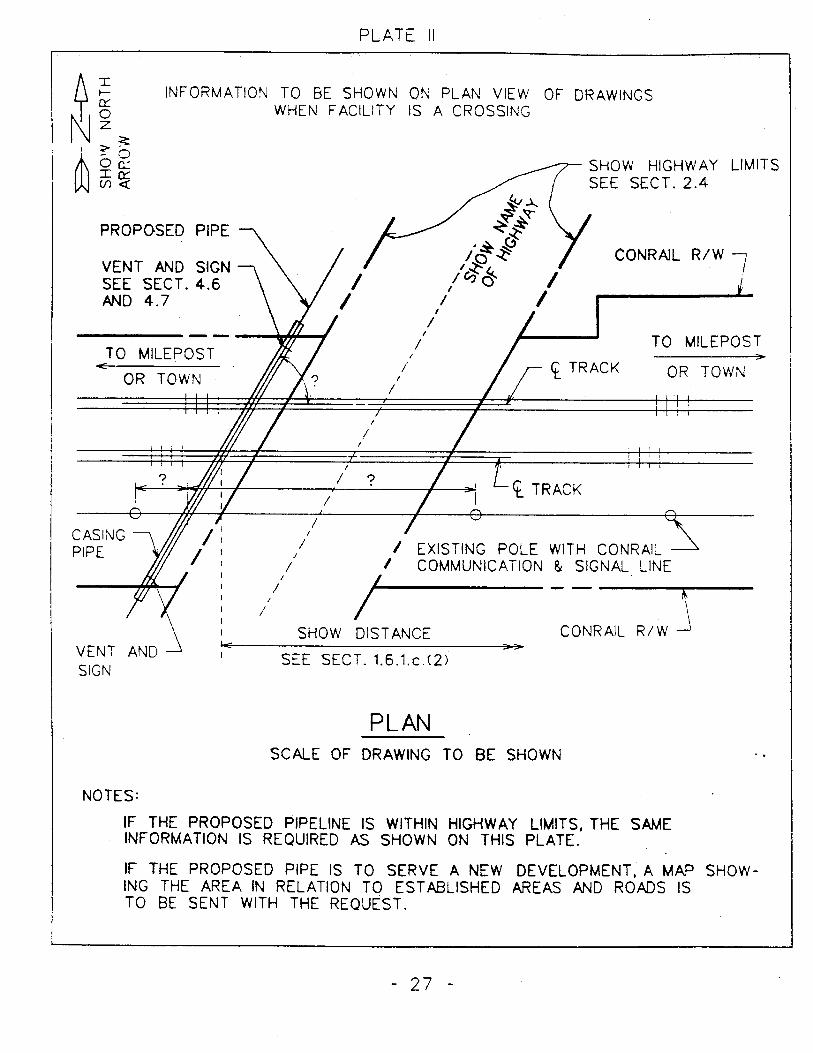
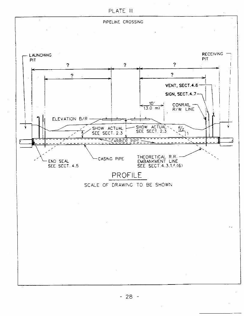
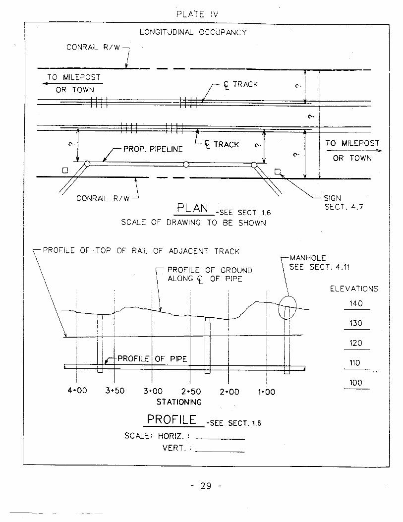
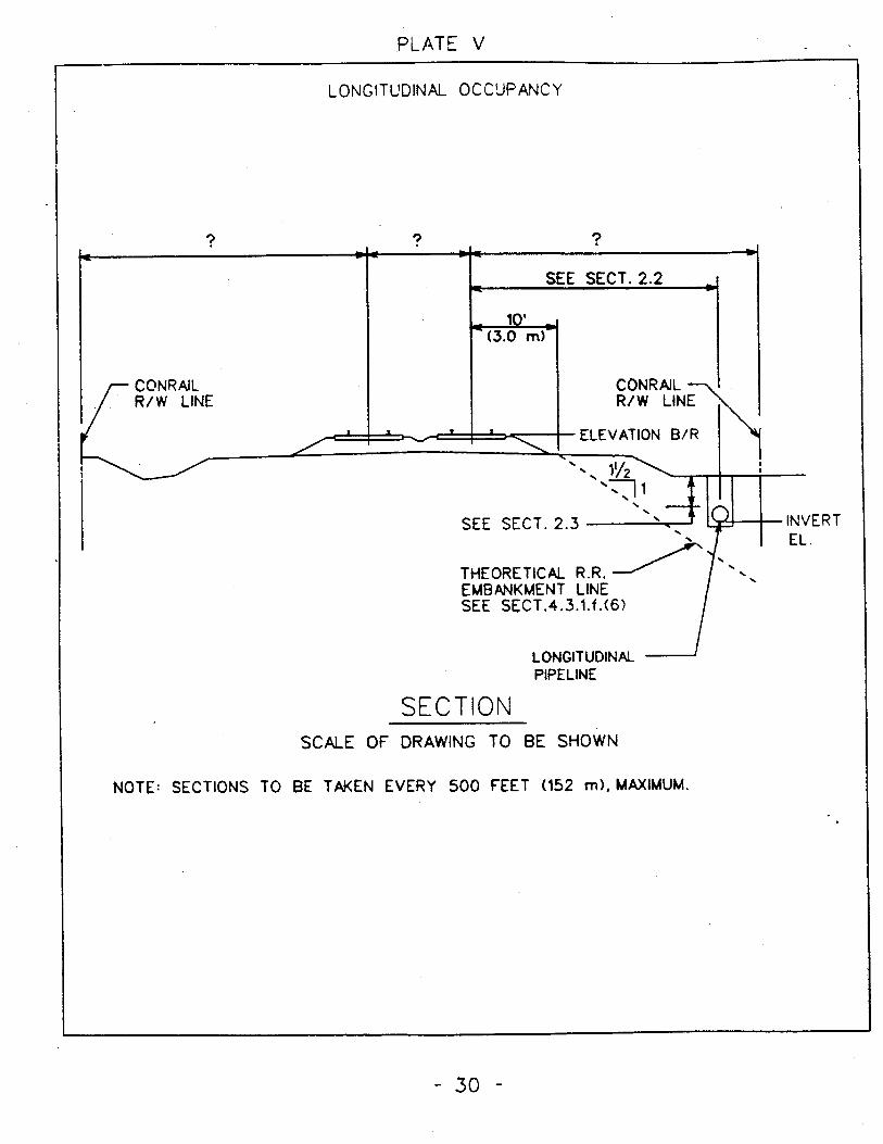
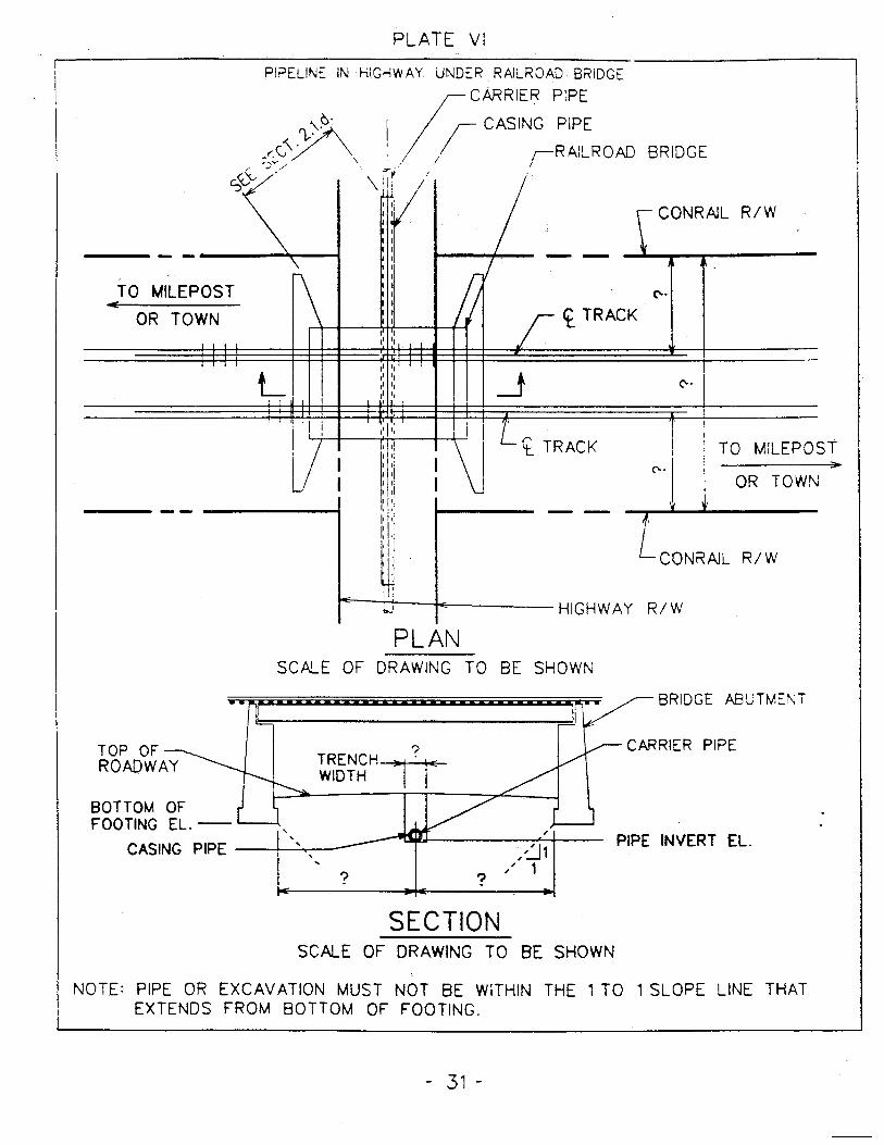
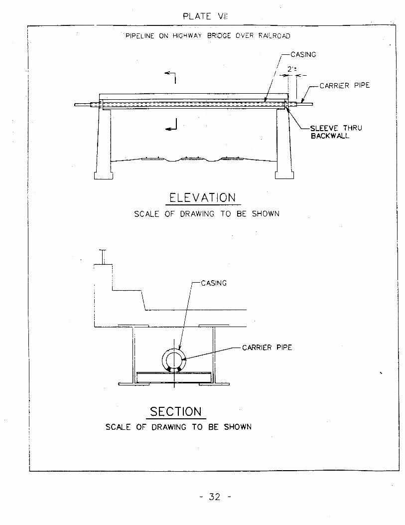
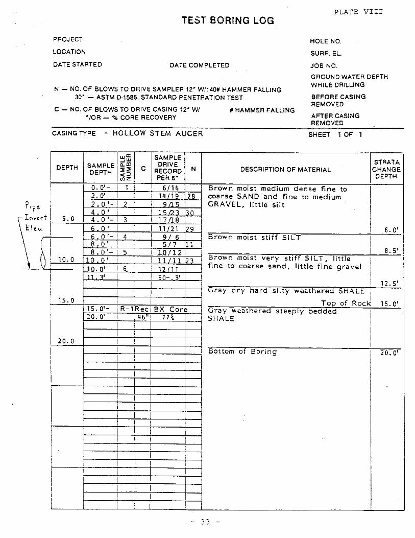
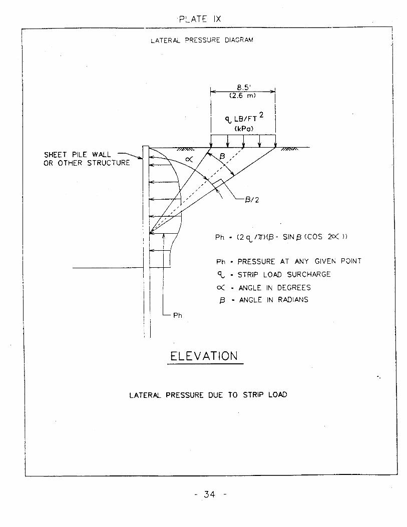
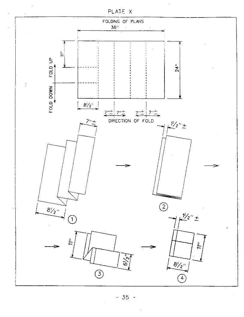

ENTRY PERMIT APPLICATION INSTRUCTIONS
The following information is required to process / circulate your request for an Entry Permit.
Please arrange your application submission in the same order as listed below.
- Contact name and phone number.
- Company’s legal name and billing address.
- Detailed description and purpose of request (engineering plans if available).
- Location description (city/county/state - provide local / county map of area with work
location highlighted).
- Work duration including estimated start & completion date.
- If environmental related, provide full details.
- Copy of existing license agreement (if applicable).
The submitted package will be forwarded to the Director - Design & Construction for
consideration. Incomplete/unclear information will result in significant delays and additional
fees.
If authorized, I will send applicant two original Entry Permits that are to be signed and returned
with the applicable fees. When executed, I will provide applicant with a Conrail field contact
name for scheduling and instructions/training.
Due to the unavailability of flagmen, the work may have to be performed during a weekend.
Do not, under any circumstances, enter Conrail property until you have an executed entry permit.
Please contact me if you have any questions.
Maria Bourassa
Manager - Engineering Contracts
4th Floor - Conrail
1000 Howard Boulevard
Mt. Laurel, NJ 08054-2355
Phone # (856) 231-2454
Fax # (856) 231-7193
e-mail: [email protected]
PROJECT SPECIFIC ATTACHMENT 4
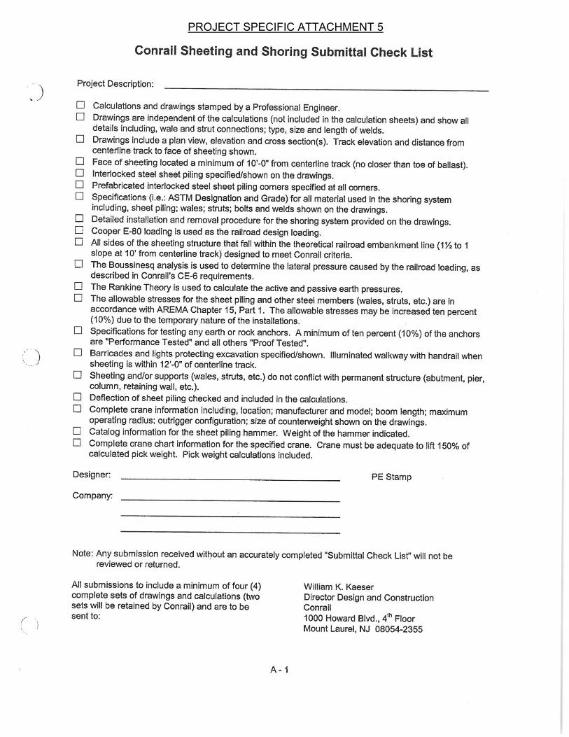
PROJECT SPECIFIC ATTACHMENT 5
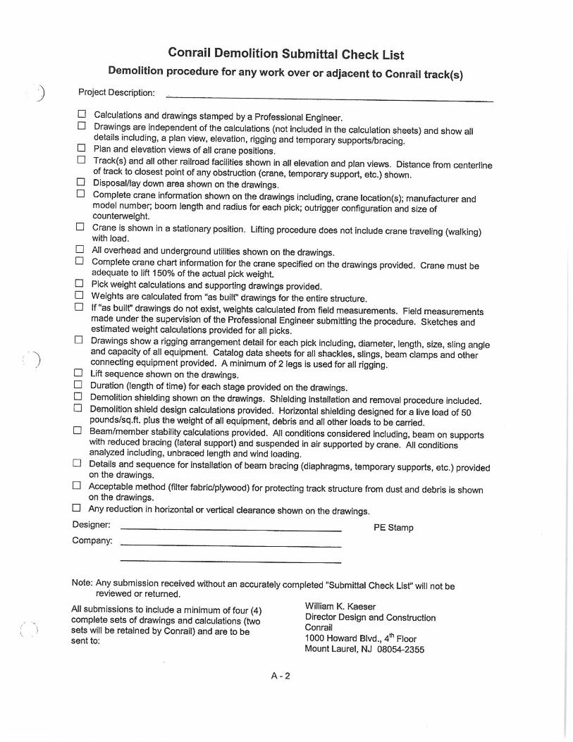
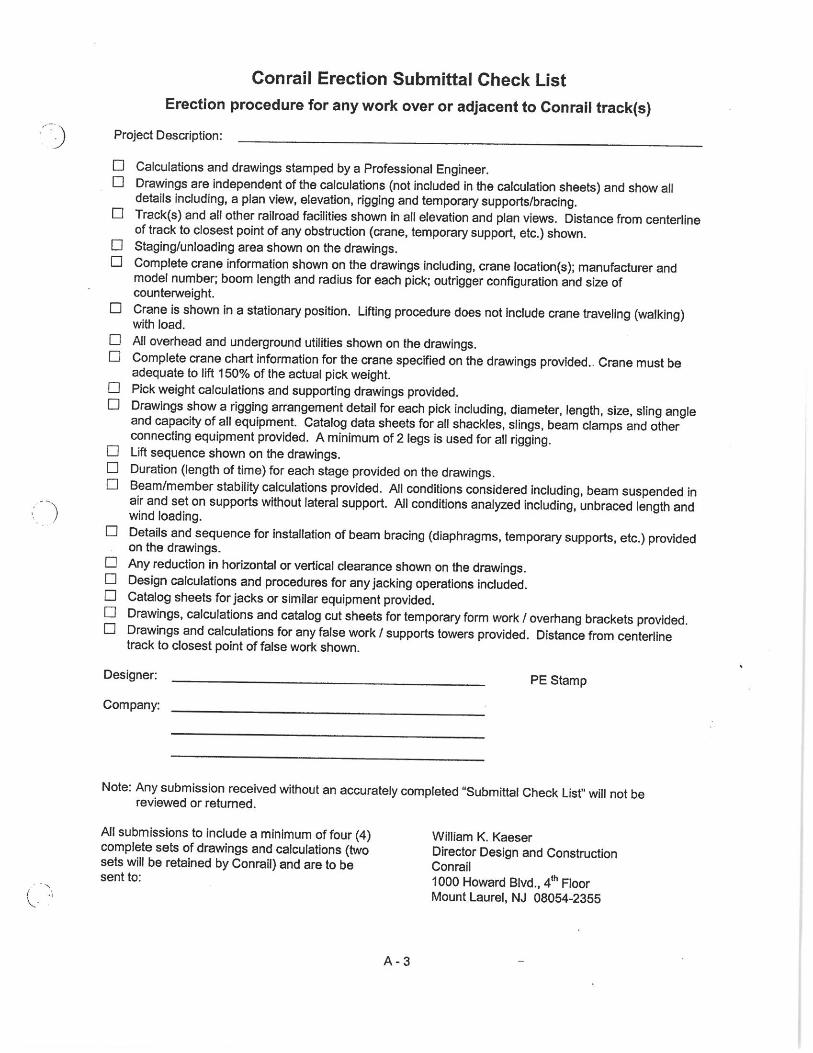
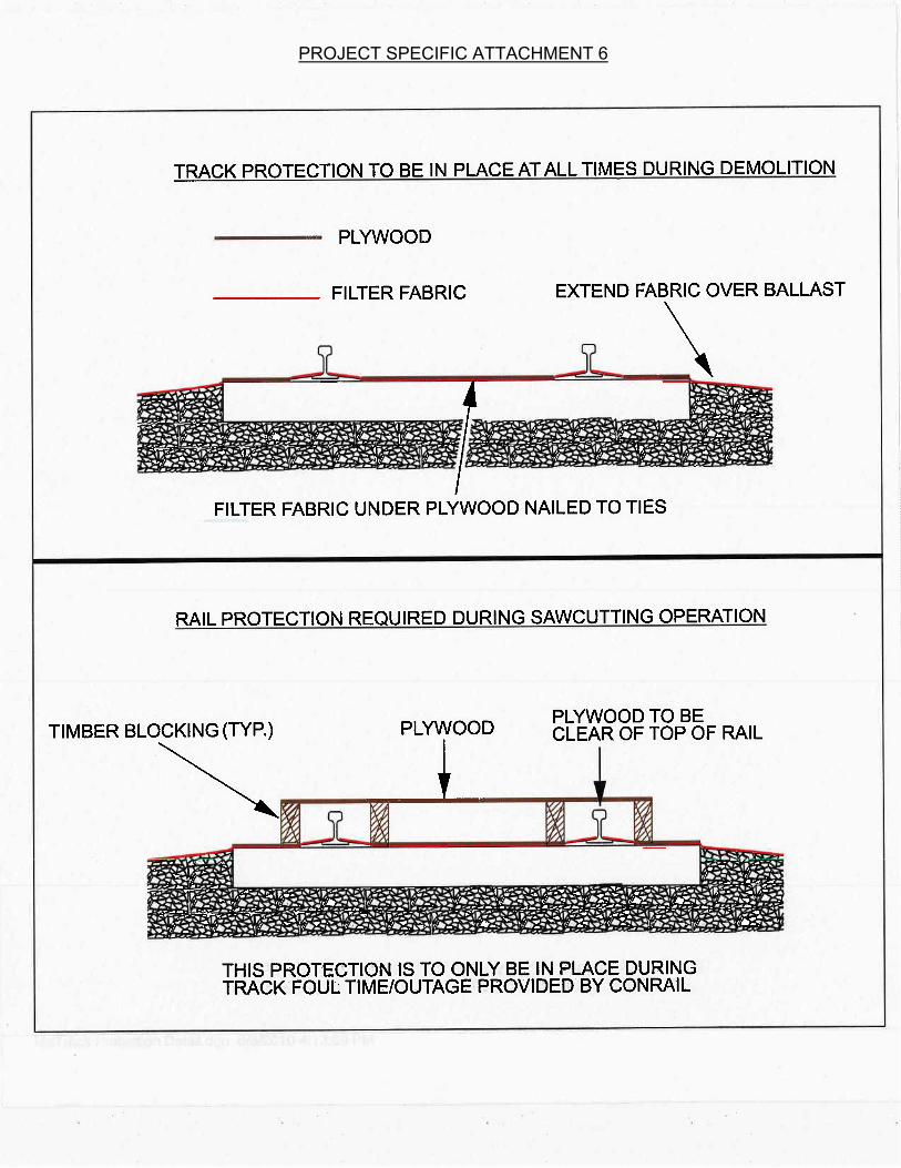
PROJECT SPECIFIC ATTACHMENT 6
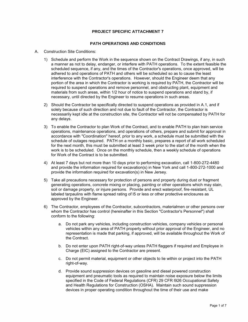
Page 1 of 7
PROJECT SPECIFIC ATTACHMENT 7
PATH OPERATIONS AND CONDITIONS
A. Construction Site Conditions:
1) Schedule and perform the Work in the sequence shown on the Contract Drawings, if any, in sucha manner as not to delay, endanger, or interfere with PATH operations. To the extent feasible thescheduled sequence, if any, and the times of the Contractor's operations, once approved, will beadhered to and operations of PATH and others will be scheduled so as to cause the leastinterference with the Contractor's operations. However, should the Engineer deem that anyportion of the area in which the Contractor is working is required by PATH, the Contractor will berequired to suspend operations and remove personnel, and obstructing plant, equipment andmaterials from such areas, within 1/2 hour of notice to suspend operations and stand by, ifnecessary, until directed by the Engineer to resume operations in such areas.
2) Should the Contractor be specifically directed to suspend operations as provided in A.1, and ifsolely because of such direction and not due to fault of the Contractor, the Contractor isnecessarily kept idle at the construction site, the Contractor will not be compensated by PATH forany delays.
3) To enable the Contractor to plan Work of the Contract, and to enable PATH to plan train serviceoperations, maintenance operations, and operations of others, prepare and submit for approval inaccordance with "Coordination" hereof, prior to any work, a schedule must be submitted with theschedule of outages required. PATH on a monthly basic, prepares a report of all work scheduledfor the next month, this must be submitted at least 3 week prior to the start of the month when thework is to be scheduled. Once on the monthly schedule, then a weekly schedule of operationsfor Work of the Contract is to be submitted.
4) At least 7 days but not more than 10 days prior to performing excavation, call 1-800-272-4480and provide the information required for excavation(s) in New York and call 1-800-272-1000 andprovide the information required for excavation(s) in New Jersey.
5) Take all precautions necessary for protection of persons and property during dust or fragmentgenerating operations, concrete mixing or placing, painting or other operations which may stain,soil or damage property, or injure persons. Provide and erect waterproof, fire-resistant, ULlabeled tarpaulins with flame spread rating of l5 or less or other protective enclosures asapproved by the Engineer.
6) The Contractor, employees of the Contractor, subcontractors, materialmen or other persons overwhom the Contractor has control (hereinafter in this Section "Contractor's Personnel") shallconform to the following:
a. Do not park any vehicles, including construction vehicles, company vehicles or personalvehicles within any area of PATH property without prior approval of the Engineer, and norepresentation is made that parking, if approved, will be available throughout the Work ofthe Contract.
b. Do not enter upon PATH right-of-way unless PATH flaggers if required and Employee inCharge (EIC) assigned to the Contractor are present.
c. Do not permit material, equipment or other objects to lie within or project into the PATHright-of-way.
d. Provide sound suppression devices on gasoline and diesel powered constructionequipment and pneumatic tools as required to maintain noise exposure below the limitsspecified in the Code of Federal Regulations (CFR) 29 CFR l926 Occupational Safetyand Health Regulations for Construction (OSHA). Maintain such sound suppressiondevices in proper operating condition throughout the time of their use and make
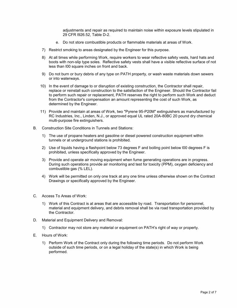
Page 2 of 7
adjustments and repair as required to maintain noise within exposure levels stipulated in 29 CFR l926.52, Table D-2.
e. Do not store combustible products or flammable materials at areas of Work.
7) Restrict smoking to areas designated by the Engineer for this purpose.
8) At all times while performing Work, require workers to wear reflective safety vests, hard hats andboots with non-slip type soles. Reflective safety vests shall have a visible reflective surface of notless than l00 square inches on front and back.
9) Do not burn or bury debris of any type on PATH property, or wash waste materials down sewersor into waterways.
10) In the event of damage to or disruption of existing construction, the Contractor shall repair,replace or reinstall such construction to the satisfaction of the Engineer. Should the Contractor failto perform such repair or replacement, PATH reserves the right to perform such Work and deductfrom the Contractor's compensation an amount representing the cost of such Work, asdetermined by the Engineer.
11) Provide and maintain at areas of Work, two "Pyrene 95-P20M" extinguishers as manufactured byRC Industries, Inc., Linden, N.J., or approved equal UL rated 20A-80BC 20 pound dry chemicalmulti-purpose fire extinguishers.
B. Construction Site Conditions in Tunnels and Stations:
1) The use of propane heaters and gasoline or diesel powered construction equipment withintunnels or at underground stations is prohibited.
2) Use of liquids having a flashpoint below 73 degrees F and boiling point below l00 degrees F isprohibited, unless specifically approved by the Engineer.
3) Provide and operate air moving equipment when fume generating operations are in progress.During such operations provide air monitoring and test for toxicity (PPM), oxygen deficiency andcombustible gas (% LEL).
4) Work will be permitted on only one track at any one time unless otherwise shown on the ContractDrawings or specifically approved by the Engineer.
C. Access To Areas of Work:
1) Work of this Contract is at areas that are accessible by road. Transportation for personnel,material and equipment delivery, and debris removal shall be via road transportation provided bythe Contractor.
D. Material and Equipment Delivery and Removal:
1) Contractor may not store any material or equipment on PATH’s right of way or property.
E. Hours of Work:
1) Perform Work of the Contract only during the following time periods. Do not perform Workoutside of such time periods, or on a legal holiday of the state(s) in which Work is beingperformed.
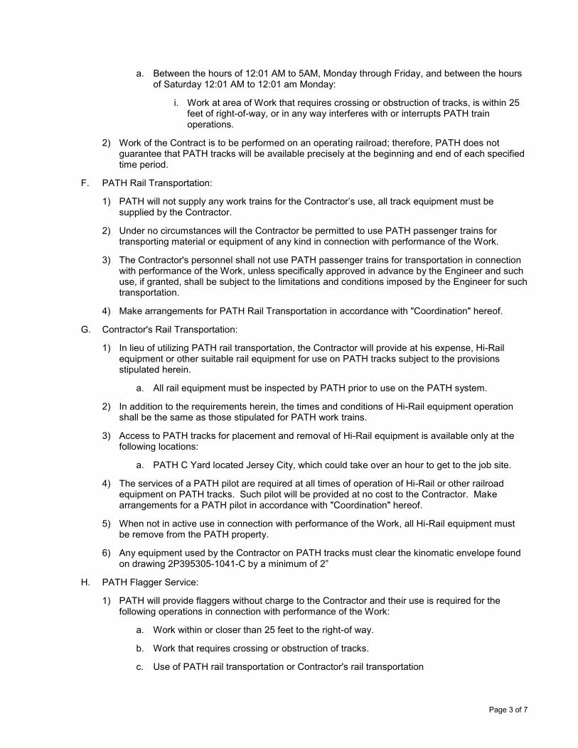
Page 3 of 7
a. Between the hours of 12:01 AM to 5AM, Monday through Friday, and between the hoursof Saturday 12:01 AM to 12:01 am Monday:
i. Work at area of Work that requires crossing or obstruction of tracks, is within 25feet of right-of-way, or in any way interferes with or interrupts PATH trainoperations.
2) Work of the Contract is to be performed on an operating railroad; therefore, PATH does notguarantee that PATH tracks will be available precisely at the beginning and end of each specifiedtime period.
F. PATH Rail Transportation:
1) PATH will not supply any work trains for the Contractor’s use, all track equipment must besupplied by the Contractor.
2) Under no circumstances will the Contractor be permitted to use PATH passenger trains fortransporting material or equipment of any kind in connection with performance of the Work.
3) The Contractor's personnel shall not use PATH passenger trains for transportation in connectionwith performance of the Work, unless specifically approved in advance by the Engineer and suchuse, if granted, shall be subject to the limitations and conditions imposed by the Engineer for suchtransportation.
4) Make arrangements for PATH Rail Transportation in accordance with "Coordination" hereof.
G. Contractor's Rail Transportation:
1) In lieu of utilizing PATH rail transportation, the Contractor will provide at his expense, Hi-Railequipment or other suitable rail equipment for use on PATH tracks subject to the provisionsstipulated herein.
a. All rail equipment must be inspected by PATH prior to use on the PATH system.
2) In addition to the requirements herein, the times and conditions of Hi-Rail equipment operationshall be the same as those stipulated for PATH work trains.
3) Access to PATH tracks for placement and removal of Hi-Rail equipment is available only at thefollowing locations:
a. PATH C Yard located Jersey City, which could take over an hour to get to the job site.
4) The services of a PATH pilot are required at all times of operation of Hi-Rail or other railroadequipment on PATH tracks. Such pilot will be provided at no cost to the Contractor. Makearrangements for a PATH pilot in accordance with "Coordination" hereof.
5) When not in active use in connection with performance of the Work, all Hi-Rail equipment mustbe remove from the PATH property.
6) Any equipment used by the Contractor on PATH tracks must clear the kinomatic envelope foundon drawing 2P395305-1041-C by a minimum of 2”
H. PATH Flagger Service:
1) PATH will provide flaggers without charge to the Contractor and their use is required for thefollowing operations in connection with performance of the Work:
a. Work within or closer than 25 feet to the right-of way.
b. Work that requires crossing or obstruction of tracks.
c. Use of PATH rail transportation or Contractor's rail transportation
Page 4 of 7
d. Work that in any way interferes with or interrupts PATH train service operations
e. Work which, in the sole discretion of the Engineer, requires flaggers for safety purposes.
2) Make arrangements for PATH flagger service in accordance with "Coordination" hereof.
I. Traction Power and Existing Utilities:
1) The Contractor's attention is called to the fact that there will be high voltage electric lines and railsfor PATH traction power at or adjacent to the areas of Work and no representation is made thatsuch lines and rails will be de-energized during performance of the Work of the Contract. TheContractor shall take all necessary precautions to protect his personnel and others affected by hisoperations from injury from such high voltage electric lines and rails. Such lines and rails willremain energized for PATH operations except where shut-off is approved by the Engineer.
2) Maintain operation of existing utility services such as compressed air, water, sewers, electricity,ventilation or fire protection and PATH surveillance cameras, signal and communication systemsduring performance of Work of the Contract, except as absolutely necessary for cutoff, cutover orother change of the affected systems, as approved by the Engineer. Coordinate with theEngineer prior to interrupting or otherwise affecting any operating system, utility or service.
3) Shut-off and turn-on of traction power or existing utility, signal or communication service will beperformed by others without cost to the Contractor.
4) PATH will not provide any compressed air, electric or lighting, Contractor is required to supply atno additional cost to PATH.
5) Notify the Engineer of such shut-off or turn-on requirements in accordance with "Coordination"hereof.
J. Coordination:
1) The progress schedule required under this Section shall contain, but not be limited to, thefollowing items:
a. Description of operations, location of Work on PATH tracks, if any
b. Start and completion dates of each operation
c. Dates and times of Work that:
i. Require closing of PATH tracks
ii. Require crossing or obstruction of tracks
iii. Is within or closer than 25 feet to right-of-way
iv. Interferes with or interrupts PATH train service operations
v. Require use of Contractor's Hi-rail equipment, if any.
2) Submit written notification to the Engineer not later than 4:00 P.M. Monday of the weekproceeding each day that the following services are required:
a. PATH rail transportation service
b. Services of PATH pilot for Contractor's rail transportation
c. PATH flagger services
d. Work to be performed within PATH tunnels
Page 5 of 7
3) Written notification shall include, but not be limited to, the following items:
a. For PATH rail transportation service:
i. The dates and locations of areas of Work
ii. Number of Contractor's personnel to be transported
b. For services of PATH pilot:
i. The dates, times and locations of Hi-rail equipment delivery to PATH trackaccess points.
ii. The dates, times and locations of areas of Work destinations of Hi-railequipment.
iii. Whether or not Hi-rail equipment will be positioned at areas of Work as a storageplatform; and if so, locations of such areas.
c. For PATH flagger services:
i. The dates, times and locations of area of Work
ii. Description of operations to be performed at areas of Work
4) Where shut-off services of PATH traction power or other utility or service are permitted, notify theEngineer not less than 3 work days prior to the anticipated need for such services. Eachnotification shall be written and shall include:
a. The dates, times and locations of areas of Work involved.
b. Description of what utility or service shut-off or turn on is required.
c. Duration of shut-off times.
K. Coordination Rescheduling or Cancellation:
When the Contractor obtains approval under "Coordination" hereof for the use of PATH services, andshould the Contractor thereafter require a rescheduling or cancellation of such services for theapproved days, submit written notification of such rescheduling or cancellation to the Engineer notless than 48 hours in advance of each day for which approval was given.
L. PATH On-Track Safety Program
PATH requires that all Contractor personnel who may enter the track area at any time be certified bysuccessfully completing the "PATH ON-TRACK SAFETY PROGRAM", in compliance with the Rulesand Regulations set forth in Federal Railroad Administration (FRA) Regulation 49 CFR Part 214,Subpart C, entitled "RAILROAD WORKER PROTECTION". Contractor personnel not certified underthis program will not be permitted to enter the PATH track area. On a monthly basis, PATH willprovide a four hour certification class at no cost to the Contractor which includes a certification test forsupervisory staff representing the Contractor by contacting Ken Bransky at 201-216-6212 or e-mail:[email protected]. The Contractor's supervisory staff will then be required to train and certify alladditional Contractor personnel that may be performing Work of the Contract. A letter certifying thatthe listed Contractor personnel have been trained on the "PATH ON-TRACK SAFETY PROGRAM"and, that they fully understand and will comply will all requirements of FRA rules, shall be filed withPATH's Safety Supervisor at One PATH Plaza, Jersey City, NJ 07306, Sixth floor, within 48 hours ofsuch training. Only the persons specified in such letter will be permitted to enter the track area.
M. No requirement of or omission to require any precautions under this Contract shall be deemed to limitor impair any responsibility or obligation assumed by the Contractor under or in connection with thisContract and the Contractor shall at all times maintain adequate protection to safeguard the public
Page 6 of 7
and all persons engaged in Work and shall take such precautions as will accomplish such end, without undue interference with the public or the operations of PATH.
N. Clearances
1) Conrail’s clearance envelope standards are adopted for PATH tracks on this project.
a. The minimum vertical clearance above the top of the higher rail shall be twenty three (23)feet (7 m) at all times. In areas where the railroad has been electrified with a catenarywire, and areas which are likely to be electrified, the minimum vertical clearance must betwenty four (24) feet, six (6) inches (7.5 m) above the top of the higher rail.
b. The minimum horizontal clearance measured from the centerline of track to the near faceof the obstruction must be twenty (20) feet (6.1 m) for tangent track and twenty one (21)feet (6.4 m) for curves. See Conrail Standard Plan 48754-B
c. The profile of the top of rail should be examined to determine if the track is in sag at thelocation of the bridge. If the track is in sag, the vertical clearance from the track to thebridge should be increased sufficiently to allow raising the track to remove the sag.
d. Vertical and horizontal clearances must be adjusted so that the sight distance to railroadsignals is not reduced from what is existing.
e. All proposed temporary clearances which are less than those listed above must besubmitted to PATH for review and must be approved by PATH prior to construction.
f. Clearances are subject to the requirements of the state in which the construction takesplace and must be approved by the State and PATH if less than those prescribed by law.
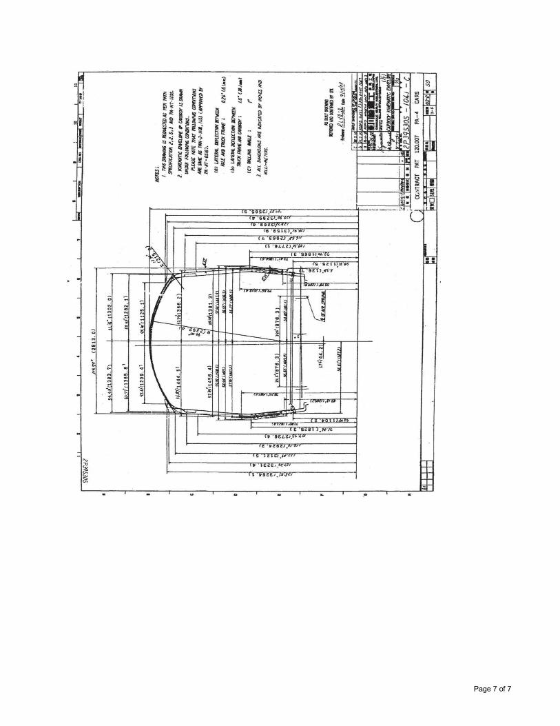
Page 7 of 7
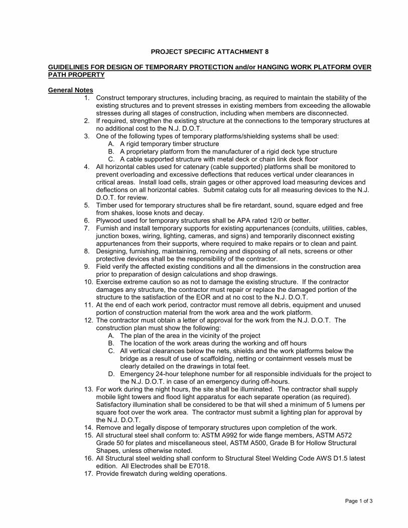
Page 1 of 3
PROJECT SPECIFIC ATTACHMENT 8
GUIDELINES FOR DESIGN OF TEMPORARY PROTECTION and/or HANGING WORK PLATFORM OVER PATH PROPERTY
General Notes 1. Construct temporary structures, including bracing, as required to maintain the stability of the
existing structures and to prevent stresses in existing members from exceeding the allowablestresses during all stages of construction, including when members are disconnected.
2. If required, strengthen the existing structure at the connections to the temporary structures atno additional cost to the N.J. D.O.T.
3. One of the following types of temporary platforms/shielding systems shall be used:A. A rigid temporary timber structureB. A proprietary platform from the manufacturer of a rigid deck type structureC. A cable supported structure with metal deck or chain link deck floor
4. All horizontal cables used for catenary (cable supported) platforms shall be monitored toprevent overloading and excessive deflections that reduces vertical under clearances incritical areas. Install load cells, strain gages or other approved load measuring devices anddeflections on all horizontal cables. Submit catalog cuts for all measuring devices to the N.J.D.O.T. for review.
5. Timber used for temporary structures shall be fire retardant, sound, square edged and freefrom shakes, loose knots and decay.
6. Plywood used for temporary structures shall be APA rated 12/0 or better.7. Furnish and install temporary supports for existing appurtenances (conduits, utilities, cables,
junction boxes, wiring, lighting, cameras, and signs) and temporarily disconnect existingappurtenances from their supports, where required to make repairs or to clean and paint.
8. Designing, furnishing, maintaining, removing and disposing of all nets, screens or otherprotective devices shall be the responsibility of the contractor.
9. Field verify the affected existing conditions and all the dimensions in the construction areaprior to preparation of design calculations and shop drawings.
10. Exercise extreme caution so as not to damage the existing structure. If the contractordamages any structure, the contractor must repair or replace the damaged portion of thestructure to the satisfaction of the EOR and at no cost to the N.J. D.O.T.
11. At the end of each work period, contractor must remove all debris, equipment and unusedportion of construction material from the work area and the work platform.
12. The contractor must obtain a letter of approval for the work from the N.J. D.O.T. Theconstruction plan must show the following:
A. The plan of the area in the vicinity of the projectB. The location of the work areas during the working and off hoursC. All vertical clearances below the nets, shields and the work platforms below the
bridge as a result of use of scaffolding, netting or containment vessels must beclearly detailed on the drawings in total feet.
D. Emergency 24-hour telephone number for all responsible individuals for the project tothe N.J. D.O.T. in case of an emergency during off-hours.
13. For work during the night hours, the site shall be illuminated. The contractor shall supplymobile light towers and flood light apparatus for each separate operation (as required).Satisfactory illumination shall be considered to be that will shed a minimum of 5 lumens persquare foot over the work area. The contractor must submit a lighting plan for approval bythe N.J. D.O.T.
14. Remove and legally dispose of temporary structures upon completion of the work.15. All structural steel shall conform to: ASTM A992 for wide flange members, ASTM A572
Grade 50 for plates and miscellaneous steel, ASTM A500, Grade B for Hollow StructuralShapes, unless otherwise noted.
16. All Structural steel welding shall conform to Structural Steel Welding Code AWS D1.5 latestedition. All Electrodes shall be E7018.
17. Provide firewatch during welding operations.
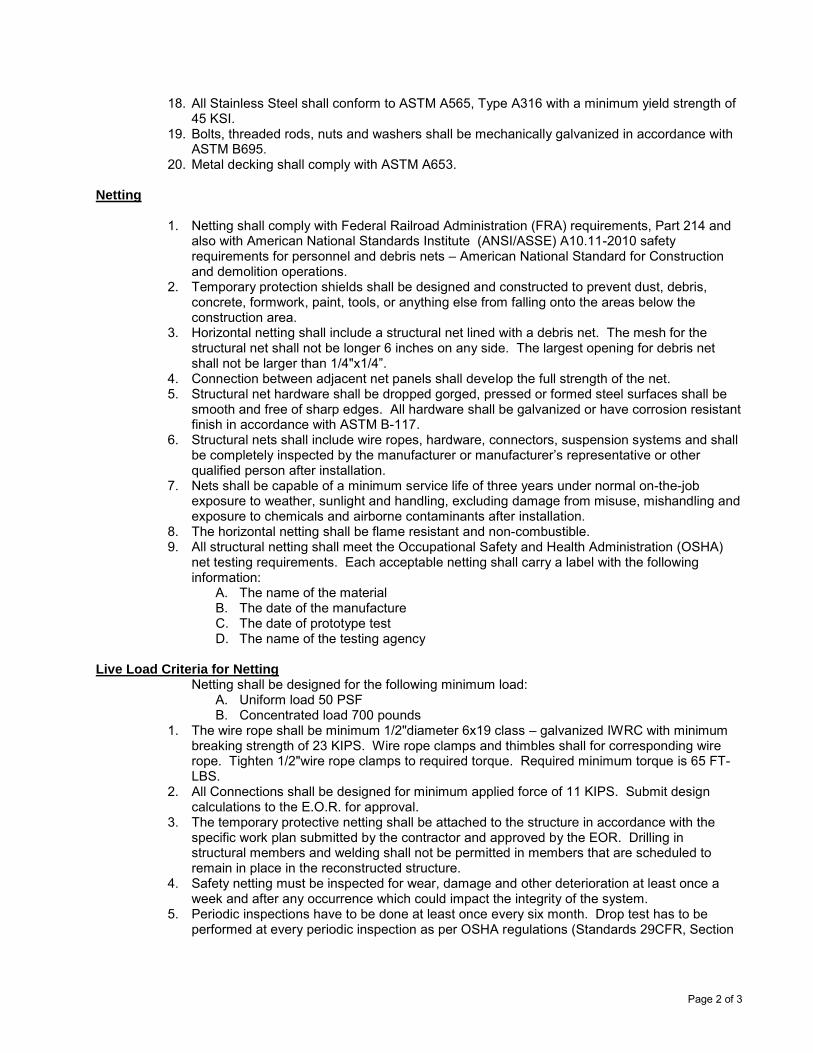
Page 2 of 3
18. All Stainless Steel shall conform to ASTM A565, Type A316 with a minimum yield strength of45 KSI.
19. Bolts, threaded rods, nuts and washers shall be mechanically galvanized in accordance withASTM B695.
20. Metal decking shall comply with ASTM A653.
Netting
1. Netting shall comply with Federal Railroad Administration (FRA) requirements, Part 214 andalso with American National Standards Institute (ANSI/ASSE) A10.11-2010 safetyrequirements for personnel and debris nets – American National Standard for Constructionand demolition operations.
2. Temporary protection shields shall be designed and constructed to prevent dust, debris,concrete, formwork, paint, tools, or anything else from falling onto the areas below theconstruction area.
3. Horizontal netting shall include a structural net lined with a debris net. The mesh for thestructural net shall not be longer 6 inches on any side. The largest opening for debris netshall not be larger than 1/4"x1/4”.
4. Connection between adjacent net panels shall develop the full strength of the net.5. Structural net hardware shall be dropped gorged, pressed or formed steel surfaces shall be
smooth and free of sharp edges. All hardware shall be galvanized or have corrosion resistantfinish in accordance with ASTM B-117.
6. Structural nets shall include wire ropes, hardware, connectors, suspension systems and shallbe completely inspected by the manufacturer or manufacturer’s representative or otherqualified person after installation.
7. Nets shall be capable of a minimum service life of three years under normal on-the-jobexposure to weather, sunlight and handling, excluding damage from misuse, mishandling andexposure to chemicals and airborne contaminants after installation.
8. The horizontal netting shall be flame resistant and non-combustible.9. All structural netting shall meet the Occupational Safety and Health Administration (OSHA)
net testing requirements. Each acceptable netting shall carry a label with the followinginformation:
A. The name of the materialB. The date of the manufactureC. The date of prototype testD. The name of the testing agency
Live Load Criteria for Netting Netting shall be designed for the following minimum load:
A. Uniform load 50 PSFB. Concentrated load 700 pounds
1. The wire rope shall be minimum 1/2"diameter 6x19 class – galvanized IWRC with minimumbreaking strength of 23 KIPS. Wire rope clamps and thimbles shall for corresponding wirerope. Tighten 1/2"wire rope clamps to required torque. Required minimum torque is 65 FT-LBS.
2. All Connections shall be designed for minimum applied force of 11 KIPS. Submit designcalculations to the E.O.R. for approval.
3. The temporary protective netting shall be attached to the structure in accordance with thespecific work plan submitted by the contractor and approved by the EOR. Drilling instructural members and welding shall not be permitted in members that are scheduled toremain in place in the reconstructed structure.
4. Safety netting must be inspected for wear, damage and other deterioration at least once aweek and after any occurrence which could impact the integrity of the system.
5. Periodic inspections have to be done at least once every six month. Drop test has to beperformed at every periodic inspection as per OSHA regulations (Standards 29CFR, Section
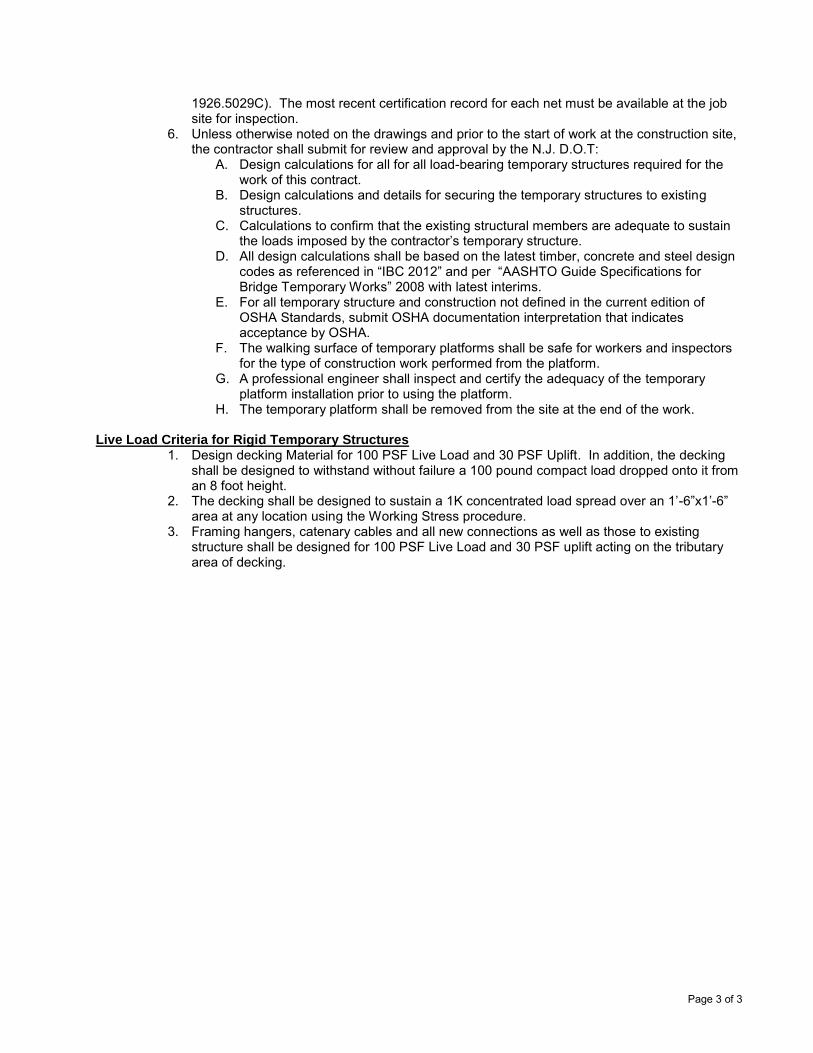
Page 3 of 3
1926.5029C). The most recent certification record for each net must be available at the job site for inspection.
6. Unless otherwise noted on the drawings and prior to the start of work at the construction site,the contractor shall submit for review and approval by the N.J. D.O.T:
A. Design calculations for all for all load-bearing temporary structures required for thework of this contract.
B. Design calculations and details for securing the temporary structures to existingstructures.
C. Calculations to confirm that the existing structural members are adequate to sustainthe loads imposed by the contractor’s temporary structure.
D. All design calculations shall be based on the latest timber, concrete and steel designcodes as referenced in “IBC 2012” and per “AASHTO Guide Specifications forBridge Temporary Works” 2008 with latest interims.
E. For all temporary structure and construction not defined in the current edition ofOSHA Standards, submit OSHA documentation interpretation that indicatesacceptance by OSHA.
F. The walking surface of temporary platforms shall be safe for workers and inspectorsfor the type of construction work performed from the platform.
G. A professional engineer shall inspect and certify the adequacy of the temporaryplatform installation prior to using the platform.
H. The temporary platform shall be removed from the site at the end of the work.
Live Load Criteria for Rigid Temporary Structures 1. Design decking Material for 100 PSF Live Load and 30 PSF Uplift. In addition, the decking
shall be designed to withstand without failure a 100 pound compact load dropped onto it froman 8 foot height.
2. The decking shall be designed to sustain a 1K concentrated load spread over an 1’-6”x1’-6”area at any location using the Working Stress procedure.
3. Framing hangers, catenary cables and all new connections as well as those to existingstructure shall be designed for 100 PSF Live Load and 30 PSF uplift acting on the tributaryarea of decking.
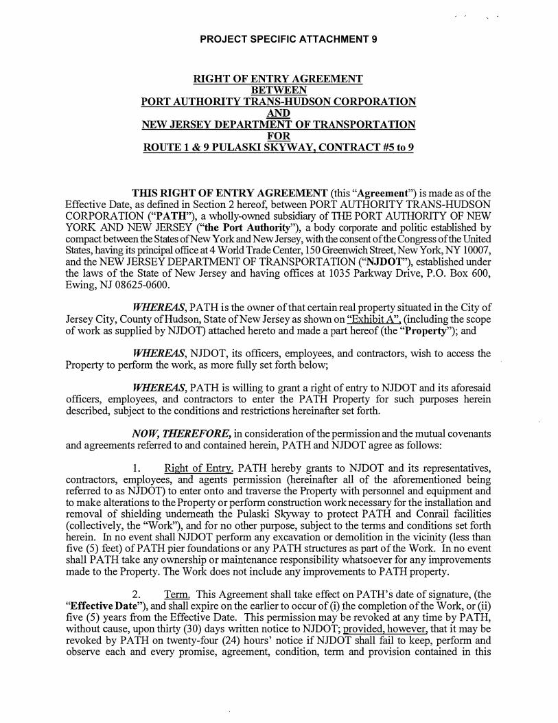
RIGHT OF ENTRY AGREEMENT BETWEEN
PORT AUTHORITY TRANS-HUDSON CORPORATION AND
NEW JERSEY DEPARTI\1ENT OF TRANSPORTATION FOR
ROUTE 1 & 9 PULASKI SKYWAY, CONTRACT #5 to 9
TIDS RIGHT OF ENTRY AGREEMENT (this "Agreement") is made as of the Effective Date, as defined in Section 2 hereof, between PORT AUTHORITY TRANS-HUDSON CORPORATION ("PATH"), a wholly-owned subsidiary of THE PORT AUTHORITY OF NEW YORK AND NEW JERSEY ("the Port Authority"), a body corporate and politic established by compact between the States ofNew York and New Jersey, with the consent of the Congress of the United States, having its principal office at 4 World Trade Center, 150 Greenwich Street, New York, NY 10007, and the NEW JERSEY DEPARTMENT OF TRANSPORTATION ("NJDOT"), established under the laws of the State of New Jersey and having offices at 1035 Parkway Drive, P.O. Box 600, Ewing, NJ 08625-0600.
WHEREAS, PATH is the owner of that certain real property situated in the City of Jersey City, County of Hudson, State of New Jersey as shown on "Exhibit A", (including the scope of work as supplied by NJDOT) attached hereto and made a part hereof (the "Property"); and
WHEREAS, NJDOT, its officers, employees, and contractors, wish to access the Property to perform the work, as more fully set forth below;
WHEREAS, PATH is willing to grant a right of entry to NJDOT and its aforesaid officers, employees, and contractors to enter the PATH Property for such purposes herein described, subject to the conditions and restrictions hereinafter set forth.
NOW, THEREFORE, in consideration of the permission and the mutual covenants and agreements referred to and contained herein, PATH and NJDOT agree as follows:
1. Right of Entry. PATH hereby grants to NJDOT and its representatives,contractors, employees, and agents permission (hereinafter all of. the aforementioned being referred to as NJDOT) to enter onto and traverse the Property with personnel and equipment and to make alterations to the Property or perform construction work necessary for the installation and removal of shielding underneath the Pulaski Skyway to protect PATH and Conrail facilities (collectively, the "Work"), and for no other purpose, subject to the terms and conditions set forth herein. In no event shall NJDOT perform any excavation or demolition in the vicinity (less than five (5) feet) of PATH pier foundations or any PATH structures as part of the Work. In no event shall PATH take any ownership or maintenance responsibility whatsoever for any improvements made to the Property. The Work does not include any improvements to PATH property.
2. Term. This Agreement shall take effect on PATH' s date of signature, ( the"Effective Date"), and shall expire on the earlier to occur of (i) the completion of the Work, or (ii) five ( 5) years from the Effective Date. This permission may be revoked at any time by PATH, without cause, upon thirty (30) days written notice to NJDOT; provided, however, that it may be revoked by PATH on twenty-four (24) hours' notice if NJDOT shall fail to keep, perform and observe each and every promise, agreement, condition, term and provision contained in this
PROJECT SPECIFIC ATTACHMENT 9


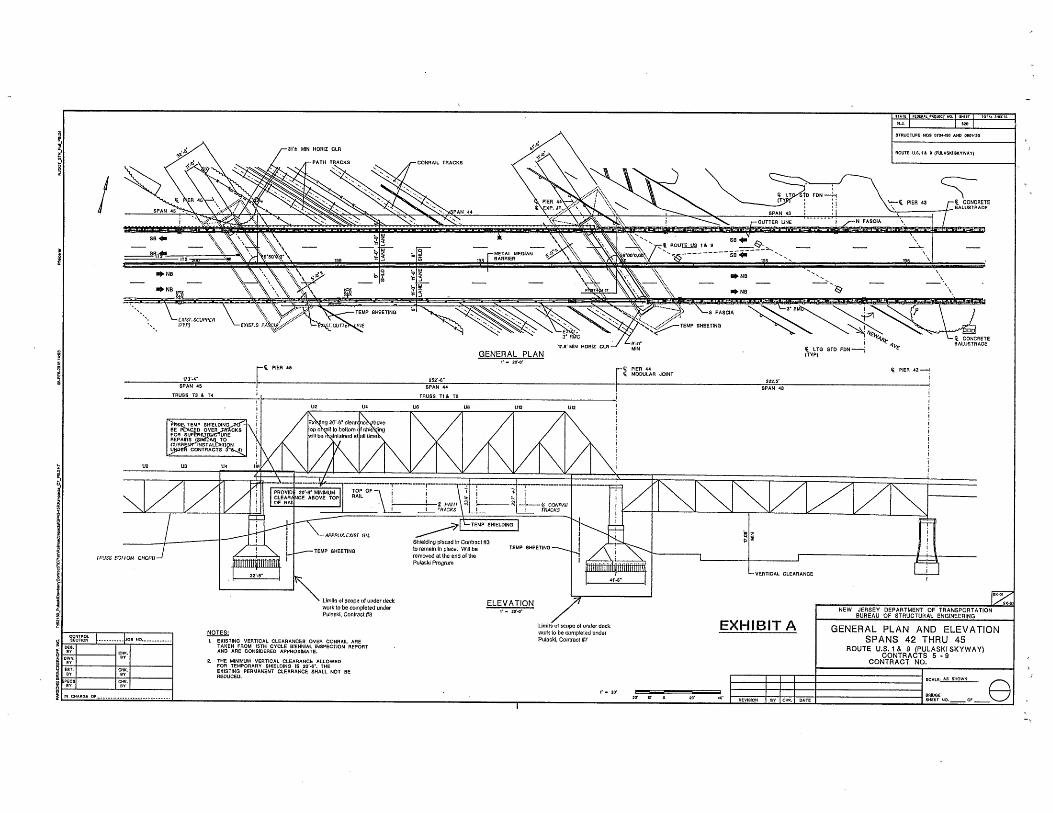

ATTACHMENT 8
GROUNDWATER TREATMENT ATTACHMENT
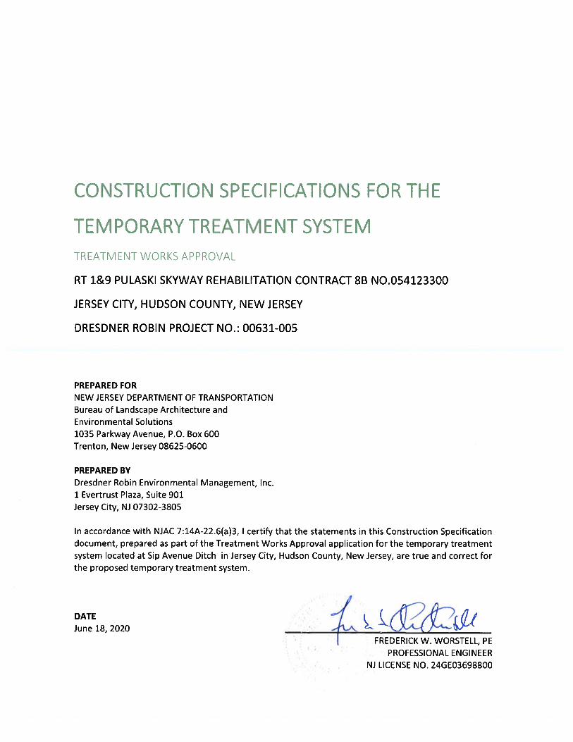
CONSTRUCTION SPECIFICATIONS FOR THE TEMPORARY TREATMENT SYSTEM DR PROJECT No.: 00631-005 TREATMENT WORKS APPROVAL JUNE 11, 2020 RT 1&9 PULASKI SKYWAY REHABILITATION CONTRACT 8B JERSEY CITY, HUDSON COUNTY, NEW JERSEY
i
TABLE OF CONTENTS
1.0 SCOPE OF WORK ...................................................................................................................................... 1
2.0 REFERENCE DOCUMENTS ......................................................................................................................... 1
3.0 DESIGN PARAMETERS .............................................................................................................................. 1
4.0 SYSTEM SUMMARY .................................................................................................................................. 2
4.1 INFLUENT SETTLING TANK ................................................................................................................. 2 4.2 SUBMERSIBLE PUMPS ....................................................................................................................... 2 4.3 BAG FILTER ASSEMBLY ...................................................................................................................... 5 4.4 LGAC VESSELS .................................................................................................................................... 5 4.5 CARTRIDGE FILTER ASSEMBLY ........................................................................................................... 5 4.6 EFFLUENT FLOW METER .................................................................................................................... 3 4.7 SYSTEM/PUMP CONTROL PANEL ASSEMBLY ..................................................................................... 4
5.0 OPERATIONS ............................................................................................................................................ 6
5.1 LICENSED OPERATOR ........................................................................................................................ 6 5.2 DISCHARGE DURATION ..................................................................................................................... 6 5.3 EMERGENCY SPILL RESPONSE ........................................................................................................... 6 5.4 RESIUDAL WASTE DIPSOAL ................................................................................................................ 7
6.0 OTHER REQUIREMENTS ............................................................................................................................ 7
LIST OF ATTACHMENTS
Proposed Settling Tank Cut Sheet
Proposed Submersible Pump Cut Sheet
Proposed Flow Meter Cut Sheet
Proposed Oil Water Separator Cut Sheet
Proposed Transfer Pump Cut Sheet
Proposed Bag Filter Housing Cut Sheet
Proposed LGAC Vessel Cut Sheet
Appendix 1
Appendix 2
Appendix 3
Appendix 4
Appendix 5
Appendix 6
Appendix 7
Appendix 8 Proposed Cartridge Filter Housing Cut Sheet
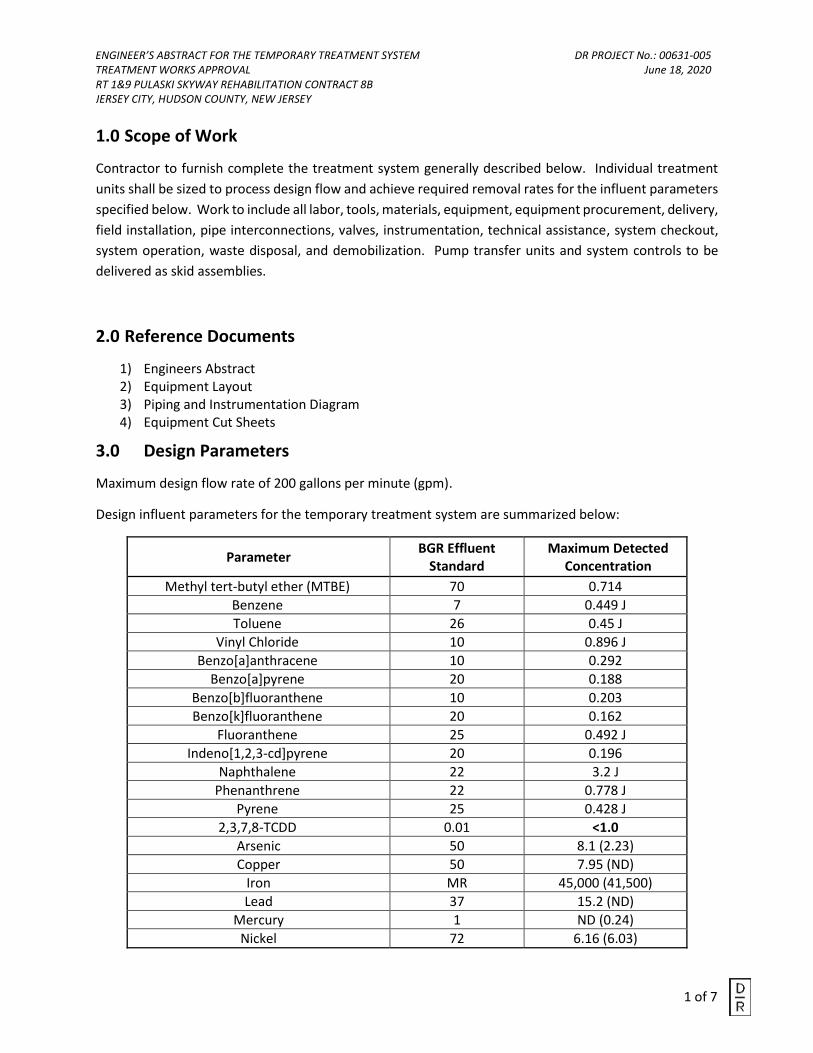
ENGINEER’S ABSTRACT FOR THE TEMPORARY TREATMENT SYSTEM DR PROJECT No.: 00631-005 TREATMENT WORKS APPROVAL June 18, 2020 RT 1&9 PULASKI SKYWAY REHABILITATION CONTRACT 8B JERSEY CITY, HUDSON COUNTY, NEW JERSEY
1 of 7
1.0 Scope of Work
Contractor to furnish complete the treatment system generally described below. Individual treatment
units shall be sized to process design flow and achieve required removal rates for the influent parameters
specified below. Work to include all labor, tools, materials, equipment, equipment procurement, delivery,
field installation, pipe interconnections, valves, instrumentation, technical assistance, system checkout,
system operation, waste disposal, and demobilization. Pump transfer units and system controls to be
delivered as skid assemblies.
2.0 Reference Documents
1) Engineers Abstract2) Equipment Layout3) Piping and Instrumentation Diagram4) Equipment Cut Sheets
3.0 Design Parameters
Maximum design flow rate of 200 gallons per minute (gpm).
Design influent parameters for the temporary treatment system are summarized below:
Parameter BGR Effluent
Standard Maximum Detected
Concentration
Methyl tert-butyl ether (MTBE) 70 0.714
Benzene 7 0.449 J
Toluene 26 0.45 J
Vinyl Chloride 10 0.896 J
Benzo[a]anthracene 10 0.292
Benzo[a]pyrene 20 0.188
Benzo[b]fluoranthene 10 0.203
Benzo[k]fluoranthene 20 0.162
Fluoranthene 25 0.492 J
Indeno[1,2,3-cd]pyrene 20 0.196
Naphthalene 22 3.2 J
Phenanthrene 22 0.778 J
Pyrene 25 0.428 J
2,3,7,8-TCDD 0.01 <1.0
Arsenic 50 8.1 (2.23)
Copper 50 7.95 (ND)
Iron MR 45,000 (41,500)
Lead 37 15.2 (ND)
Mercury 1 ND (0.24)
Nickel 72 6.16 (6.03)
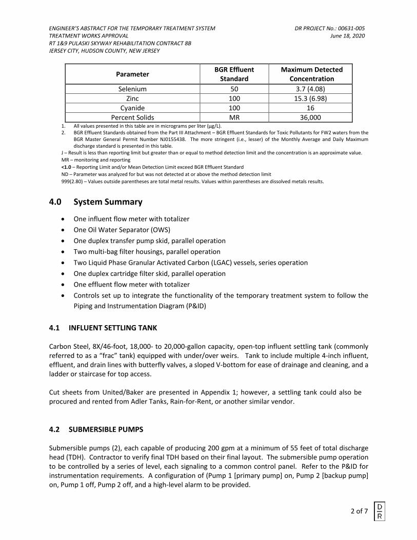
ENGINEER’S ABSTRACT FOR THE TEMPORARY TREATMENT SYSTEM DR PROJECT No.: 00631-005 TREATMENT WORKS APPROVAL June 18, 2020 RT 1&9 PULASKI SKYWAY REHABILITATION CONTRACT 8B JERSEY CITY, HUDSON COUNTY, NEW JERSEY
2 of 7
Parameter BGR Effluent
Standard Maximum Detected
Concentration
Selenium 50 3.7 (4.08)
Zinc 100 15.3 (6.98)
Cyanide 100 16
Percent Solids MR 36,000 1. All values presented in this table are in micrograms per liter (µg/L).2. BGR Effluent Standards obtained from the Part III Attachment – BGR Effluent Standards for Toxic Pollutants for FW2 waters from the
BGR Master General Permit Number NJ0155438. The more stringent (i.e., lesser) of the Monthly Average and Daily Maximum discharge standard is presented in this table.
J – Result is less than reporting limit but greater than or equal to method detection limit and the concentration is an approximate value.
MR – monitoring and reporting
<1.0 – Reporting Limit and/or Mean Detection Limit exceed BGR Effluent Standard
ND – Parameter was analyzed for but was not detected at or above the method detection limit
999(2.80) – Values outside parentheses are total metal results. Values within parentheses are dissolved metals results.
4.0 System Summary
• One influent flow meter with totalizer
• One Oil Water Separator (OWS)
• One duplex transfer pump skid, parallel operation
• Two multi-bag filter housings, parallel operation
• Two Liquid Phase Granular Activated Carbon (LGAC) vessels, series operation
• One duplex cartridge filter skid, parallel operation
• One effluent flow meter with totalizer
• Controls set up to integrate the functionality of the temporary treatment system to follow the
Piping and Instrumentation Diagram (P&ID)
4.1 INFLUENT SETTLING TANK
Carbon Steel, 8X/46-foot, 18,000- to 20,000-gallon capacity, open-top influent settling tank (commonly referred to as a “frac” tank) equipped with under/over weirs. Tank to include multiple 4-inch influent, effluent, and drain lines with butterfly valves, a sloped V-bottom for ease of drainage and cleaning, and a ladder or staircase for top access.
Cut sheets from United/Baker are presented in Appendix 1; however, a settling tank could also be procured and rented from Adler Tanks, Rain-for-Rent, or another similar vendor.
4.2 SUBMERSIBLE PUMPS
Submersible pumps (2), each capable of producing 200 gpm at a minimum of 55 feet of total discharge head (TDH). Contractor to verify final TDH based on their final layout. The submersible pump operation to be controlled by a series of level, each signaling to a common control panel. Refer to the P&ID for instrumentation requirements. A configuration of (Pump 1 [primary pump] on, Pump 2 [backup pump] on, Pump 1 off, Pump 2 off, and a high-level alarm to be provided.
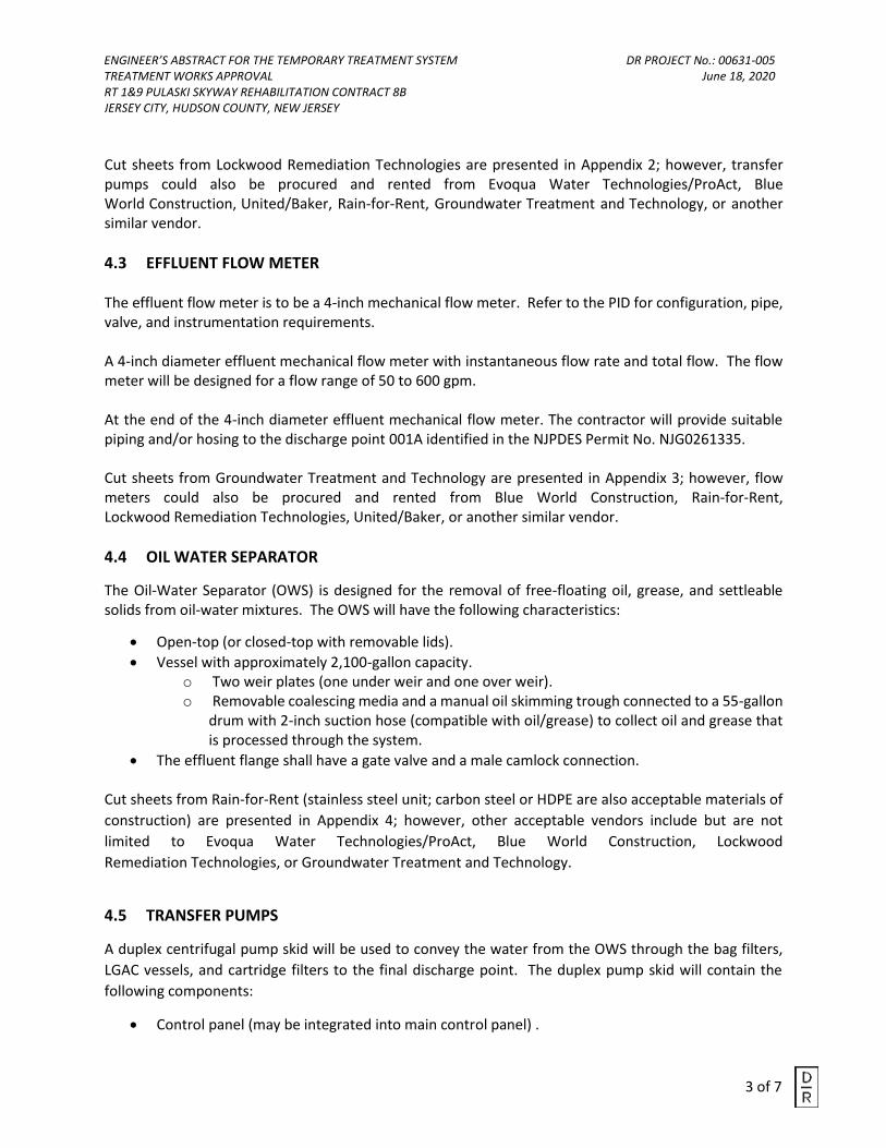
ENGINEER’S ABSTRACT FOR THE TEMPORARY TREATMENT SYSTEM DR PROJECT No.: 00631-005 TREATMENT WORKS APPROVAL June 18, 2020 RT 1&9 PULASKI SKYWAY REHABILITATION CONTRACT 8B JERSEY CITY, HUDSON COUNTY, NEW JERSEY
3 of 7
Cut sheets from Lockwood Remediation Technologies are presented in Appendix 2; however, transfer pumps could also be procured and rented from Evoqua Water Technologies/ProAct, Blue World Construction, United/Baker, Rain-for-Rent, Groundwater Treatment and Technology, or another similar vendor.
4.3 EFFLUENT FLOW METER
The effluent flow meter is to be a 4-inch mechanical flow meter. Refer to the PID for configuration, pipe, valve, and instrumentation requirements.
A 4-inch diameter effluent mechanical flow meter with instantaneous flow rate and total flow. The flow meter will be designed for a flow range of 50 to 600 gpm.
At the end of the 4-inch diameter effluent mechanical flow meter. The contractor will provide suitable piping and/or hosing to the discharge point 001A identified in the NJPDES Permit No. NJG0261335.
Cut sheets from Groundwater Treatment and Technology are presented in Appendix 3; however, flow meters could also be procured and rented from Blue World Construction, Rain-for-Rent, Lockwood Remediation Technologies, United/Baker, or another similar vendor.
4.4 OIL WATER SEPARATOR
The Oil-Water Separator (OWS) is designed for the removal of free-floating oil, grease, and settleable solids from oil-water mixtures. The OWS will have the following characteristics:
• Open-top (or closed-top with removable lids).
• Vessel with approximately 2,100-gallon capacity.o Two weir plates (one under weir and one over weir).o Removable coalescing media and a manual oil skimming trough connected to a 55-gallon
drum with 2-inch suction hose (compatible with oil/grease) to collect oil and grease thatis processed through the system.
• The effluent flange shall have a gate valve and a male camlock connection.
Cut sheets from Rain-for-Rent (stainless steel unit; carbon steel or HDPE are also acceptable materials of
construction) are presented in Appendix 4; however, other acceptable vendors include but are not
limited to Evoqua Water Technologies/ProAct, Blue World Construction, Lockwood
Remediation Technologies, or Groundwater Treatment and Technology.
4.5 TRANSFER PUMPS
A duplex centrifugal pump skid will be used to convey the water from the OWS through the bag filters,
LGAC vessels, and cartridge filters to the final discharge point. The duplex pump skid will contain the
following components:
• Control panel (may be integrated into main control panel) .
ENGINEER’S ABSTRACT FOR THE TEMPORARY TREATMENT SYSTEM DR PROJECT No.: 00631-005 TREATMENT WORKS APPROVAL June 18, 2020 RT 1&9 PULASKI SKYWAY REHABILITATION CONTRACT 8B JERSEY CITY, HUDSON COUNTY, NEW JERSEY
4 of 7
• Two full-capacity centrifugal pumps installed in parallel, in a lead-lag configuration.
o Each pump shall be capable of producing 240 gpm at approximately 75 feet TDH.
o System contractor/vendor shall verify final hydraulic/TDH requirements based on the site
conditions, layout of the system, and surface water discharge point providing sufficient
contingency in the selection of the pumps to achieve the necessary flow rate.
o Each pump shall be equipped with a 7.5-HP, 460-volt, 3-phase electric TEFC motor with
50 feet of feed wire connected to the temporary power source
o The transfer pump operation shall be controlled by four level switches located within the
effluent chamber of the OWS that will signal to the control panel (Pump 1 (lead pump)
on, Pump 2 (lag pump) on, Pump 1 off, Pump 2 off, and a high-level alarm).
▪ At the high-level condition, the high-level switch shall activate an alarm light to
alert the operator. In this condition, the operator shall throttle back the influent
flow from the OWS, until the OWS duplex pumps are able to reduce the level in
the effluent reservoir and keep up with the overall influent flow.
o Each pump shall have a pressure indicator, check valve, and gate valve provided on the
discharge end.
o The transfer pumps shall be furnished manifolded together or be manifolded in the field.
o Each pump shall be provided with a drain valve to winterize the pump system, if needed.
Cut sheets from Lockwood Remediation Technologies are presented in Appendix 5; however, other
acceptable vendors include but are not limited to Evoqua Water Technologies/ProAct, Blue World
Construction, United/Baker, Rain-for-Rent, or Groundwater Treatment and Technology.
4.6 SYSTEM/PUMP CONTROL PANEL ASSEMBLY
Centralized control panel assembly contained in a UL rated weather-proof enclosure to power equipment, controllers and instrumentation.
The control panel to contain four motor starters, four Moeller PKZ2 (or similar) overloads, four pump switches (hand/off/auto) with indicator lights located on the panel, two warning lights for the high-level settling tank and high-level OWS, and one 480-volt, 3-phase, 100-amp fused disconnect (or sized to match jobsite power source).
If different power is provided (208, 240-volt three phase) the contractor must reverify all motor, wiring, contactor and overload selections before final installation.
Blue World Construction, Rain-for-Rent, Lockwood Remediation Technologies, Groundwater Treatment and Technology, or another similar vendor. Control panels could also be procured and rented from a controls vendor such as Product Level Control (PLC).
ENGINEER’S ABSTRACT FOR THE TEMPORARY TREATMENT SYSTEM DR PROJECT No.: 00631-005 TREATMENT WORKS APPROVAL June 18, 2020 RT 1&9 PULASKI SKYWAY REHABILITATION CONTRACT 8B JERSEY CITY, HUDSON COUNTY, NEW JERSEY
5 of 7
4.7 BAG FILTER ASSEMBLY
The bag filter assembly will consist of the following components:
• Duplex Filter Cartridges (2)
• Submersible Transfer Pump (1)
• 55 Gallon storage drum (1)
• Pipe, valves, interconnects, pressure gauges, drain/sample ports (Refer to the PID forconfiguration, pipe, valve, details and instrumentation)
The two multi-bag filter housings, each rated for a maximum 200 gpm and 150 pounds per square inch (psi), three 5-micron bag filters for solids removal, ±13.2 square feet of filter area. Housings plumbed in parallel, pressure gauges, isolation valve on each unit inlet and outlet. each housing to be provided with isolation valves. The 55-gallon drum will contain a submersible pump (approximately 1/3-HP, 120-volt, single phase) with an automatic float connected to the submersible pump.
Cut sheets from United/Baker are presented in Appendix 6; however, bag filter housings could also be procured and rented from Evoqua Water Technologies/ProAct, Blue World Construction, Lockwood Remediation Technologies, Rain-for-Rent, Groundwater Treatment and Technology, or another similar vendor.
4.8 LIQUID PHASE GRANULAR ACTIVATED CARBON VESSELS
The LGAC system will consist of the following components:
• LGAC Vessels
• Activated Carbon
• Pipe, valves, interconnects, pressure gauges, drain/sample ports (Refer to the PID forconfiguration, pipe, valve, and instrumentation requirements)
Two high pressure LGAC vessels (designed for a maximum pressure of 75 psi), each to contain approximately 4,000 pounds (lbs) of reactivated carbon. Units to be configured for lead-lag series configuration. The LGAC vessels will be equipped with manual drains, sample ports, pressure gauges. Each LGAC vessel to be equipped with a pressure relief valve (PRV) and air relief valve (ARV). The carbon media to be hydrated (soaked) in clean water (provided by others) for a minimum of 24 hours prior to use.
Cut sheets from Evoqua Water Technologies/ProAct are presented in Attachment 7; however, LGAC vessels could also be procured and rented from United/Baker, Blue World Construction, Lockwood Remediation Technologies, Groundwater Treatment and Technology, or another similar vendor.
4.9 CARTRIDGE FILTER ASSEMBLY
The cartridge filter assembly will consist of:
• Duplex Filter Cartridges
ENGINEER’S ABSTRACT FOR THE TEMPORARY TREATMENT SYSTEM DR PROJECT No.: 00631-005 TREATMENT WORKS APPROVAL June 18, 2020 RT 1&9 PULASKI SKYWAY REHABILITATION CONTRACT 8B JERSEY CITY, HUDSON COUNTY, NEW JERSEY
6 of 7
• Submersible Transfer Pump
• 55 Gallon storage drum
• Pipe, valves, interconnects, pressure gauges, drain/sample ports
• See PID for configuration, pipe, valve, and instrumentation requirements
The duplex cartridge filter skid will include multi-cartridge filter housings (2), each with a nominal capacity of 250 gpm, containing twelve 30-inch long, 1-micron cartridge filters, plumbed in parallel. Individual filter cartridge assemblies to include inlet and outlet isolation valves and pressure gauges.
Cut sheets from United/Baker are presented in Appendix 8; however, cartridge filter housings can also be procured and rented from Evoqua Water Technologies/ProAct, Blue World Construction, Lockwood Remediation Technologies, Groundwater Treatment and Technology, or another similar vendor.
5.0 OPERATIONS
5.1 LICENSED OPERATOR
The temporary treatment system vendor will provide a Licensed Operator responsible for operation and
maintenance (O&M), routine sampling of treatment system effluent, and the preparation of
monthly discharge monitoring reports (DMR) to be submitted to the New Jersey Department of
Environmental Protection (NJDEP) In accordance with the discharge to surface permit (NJPDES Permit
No. NJG0261335). The Licensed Operator will be a permanent, full-time employee of the
temporary treatment system vendor. Prior to startup, the name of the proposed Licensed Operator
will be submitted to NJDEP.
5.2 DISCHARGE DURATION
The discharge duration and monitoring of the treatment system is assumed to be 8 hours-a-day, 5 days-
a-week. Remote monitoring or 24-hour onsite monitoring will be implemented if duration exceeds
the specified timeframe. A water allocation permit will be required if dewatering exceeds 100,000
gallons per day.
5.3 EMERGENCY SPILL RESPONSE
An emergency spill kit, capable of containing 95 gallons of spill, will be placed inside the treatment unit
trailer, maintained and readily accessible. The contents of the spill kit will include but not limited to the
following:
• An instruction manual and emergency response guide.
• Ten 5-inch × 10-foot oil-only absorbent booms.
• Ten 3-inch × 10-foot oil-only absorbent booms.
• One hundred 20 × 16-inch oil-only absorbent pads.
• Twenty temporary disposal bags and ties.
• A 40-pound bag of loose absorbent pellets.
• A wheeled container for the above.
ENGINEER’S ABSTRACT FOR THE TEMPORARY TREATMENT SYSTEM DR PROJECT No.: 00631-005 TREATMENT WORKS APPROVAL June 18, 2020 RT 1&9 PULASKI SKYWAY REHABILITATION CONTRACT 8B JERSEY CITY, HUDSON COUNTY, NEW JERSEY
7 of 7
5.4 RESIDUAL WASTE DISPOSAL
Liquids and solid residual waste will be disposed offsite in accordance with applicable hazardous and non-
hazardous waste disposal regulations:
• Spent carbon media will be sampled and profiled to determine if it is hazardous or nonhazardous.
It is expected to be regenerated for re-use at an appropriately licensed and permitted
regeneration facility or disposed of off-site at an appropriately licensed and permitted landfill.
• Residuals from the frac tanks will be characterized (as necessary), manifested, and disposed of
off-site at an appropriately licensed and permitted landfill.
• Spent bag and cartridge filters will be characterized (as necessary), manifested, and disposed of
off-site (by others) at an appropriately licensed and permitted landfill.
6.0 OTHER REQUIREMENTS
1) Prior to treatment system mobilization, the Contractor will construct a 6-inch thick pad using
crushed ¾ inch clean stone or other suitable supporting material to ensure the treatment
system is constructed on a sound and level surface.
2) System elements to be properly insulated for winter operations.
3) All pipe, hose, fittings, and valves shall be compatible with listed influent contaminants. All
piping will be Schedule 40 polyvinyl chloride (PVC) at a minimum. Connective plumbing to be
appropriately sized per supplier recommendations for treatment unit operations.
4) All spent material (i.e. bag filters, cartridge filters carbon media, etc) will be replenished by the
treatment system vendor.

APPENDIX 1
Proposed Settling Tank
Cut Sheet
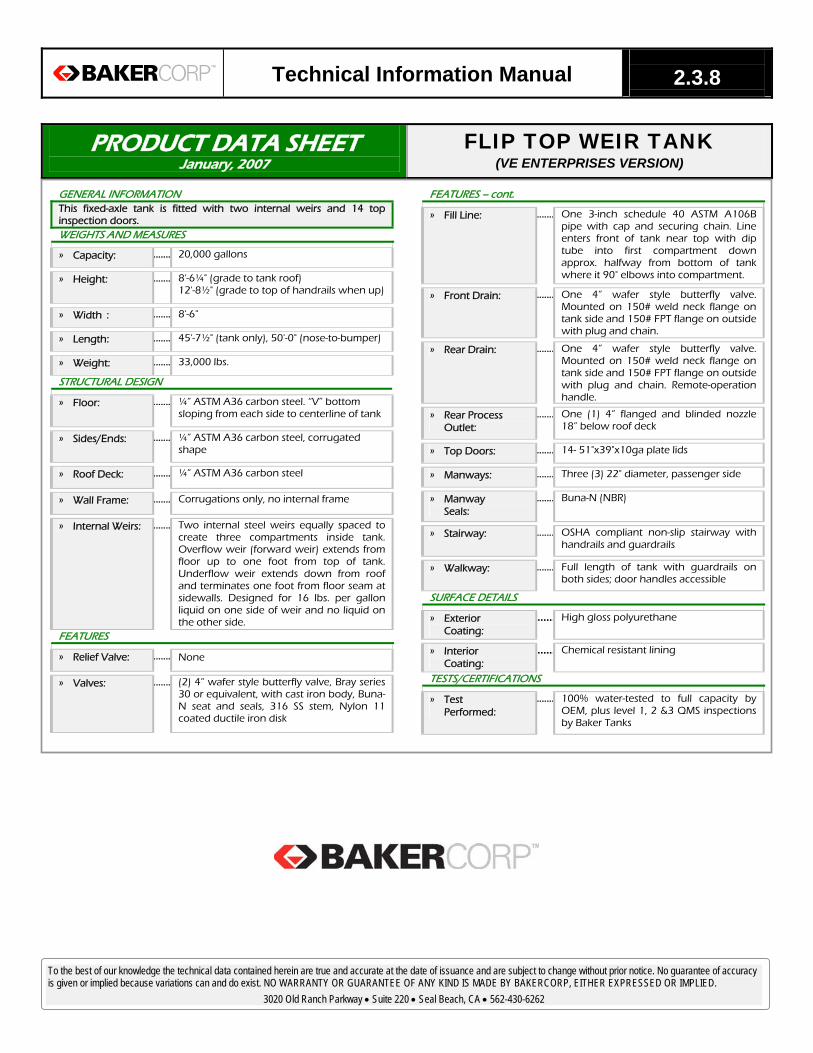
Technical Information Manual 2.3.8
PRODUCT DATA SHEET January, 2007
FLIP TOP WEIR TANK (VE ENTERPRISES VERSION)
GENERAL INFORMATION This fixed-axle tank is fitted with two internal weirs and 14 top inspection doors. WEIGHTS AND MEASURES
» Capacity: ....... 20,000 gallons
» Height: ....... 8'-6¼" (grade to tank roof) 12'-8½" (grade to top of handrails when up)
» Width : ....... 8'-6"
» Length: ....... 45'-7½" (tank only), 50'-0" (nose-to-bumper)
» Weight: ....... 33,000 lbs.
STRUCTURAL DESIGN
» Floor: ....... ¼” ASTM A36 carbon steel. “V” bottom sloping from each side to centerline of tank
» Sides/Ends: ....... ¼” ASTM A36 carbon steel, corrugated shape
» Roof Deck: ....... ¼” ASTM A36 carbon steel
» Wall Frame: ....... Corrugations only, no internal frame
» Internal Weirs: ....... Two internal steel weirs equally spaced to create three compartments inside tank. Overflow weir (forward weir) extends from floor up to one foot from top of tank. Underflow weir extends down from roof and terminates one foot from floor seam at sidewalls. Designed for 16 lbs. per gallon liquid on one side of weir and no liquid on the other side.
FEATURES
» Relief Valve: ....... None
» Valves: ....... (2) 4” wafer style butterfly valve, Bray series30 or equivalent, with cast iron body, Buna-N seat and seals, 316 SS stem, Nylon 11coated ductile iron disk
To the best of our knowledge the technical data contained herein are true and accurate at the date of issuance and are subject to change without prior notice. No guarantee of accuracy is given or implied because variations can and do exist. NO WARRANTY OR GUARANTEE OF ANY KIND IS MADE BY BAKERCORP, EITHER EXPRESSED OR IMPLIED.
3020 Old Ranch Parkway • Suite 220 • Seal Beach, CA • 562-430-6262
FEATURES – cont.
» Fill Line: ....... One 3-inch schedule 40 ASTM A106B pipe with cap and securing chain. Line enters front of tank near top with dip tube into first compartment down approx. halfway from bottom of tank where it 90° elbows into compartment.
» Front Drain: ....... One 4” wafer style butterfly valve. Mounted on 150# weld neck flange on tank side and 150# FPT flange on outside with plug and chain.
» Rear Drain: ....... One 4” wafer style butterfly valve. Mounted on 150# weld neck flange on tank side and 150# FPT flange on outside with plug and chain. Remote-operation handle.
» Rear ProcessOutlet:
....... One (1) 4” flanged and blinded nozzle 18” below roof deck
» Top Doors: ....... 14- 51"x39"x10ga plate lids
» Manways: ....... Three (3) 22" diameter, passenger side
» Manway Seals:
....... Buna-N (NBR)
» Stairway: ....... OSHA compliant non-slip stairway with handrails and guardrails
» Walkway: ....... Full length of tank with guardrails on both sides; door handles accessible
SURFACE DETAILS
» ExteriorCoating:
...... High gloss polyurethane
» InteriorCoating:
...... Chemical resistant lining
TESTS/CERTIFICATIONS
» TestPerformed:
....... 100% water-tested to full capacity by OEM, plus level 1, 2 &3 QMS inspections by Baker Tanks
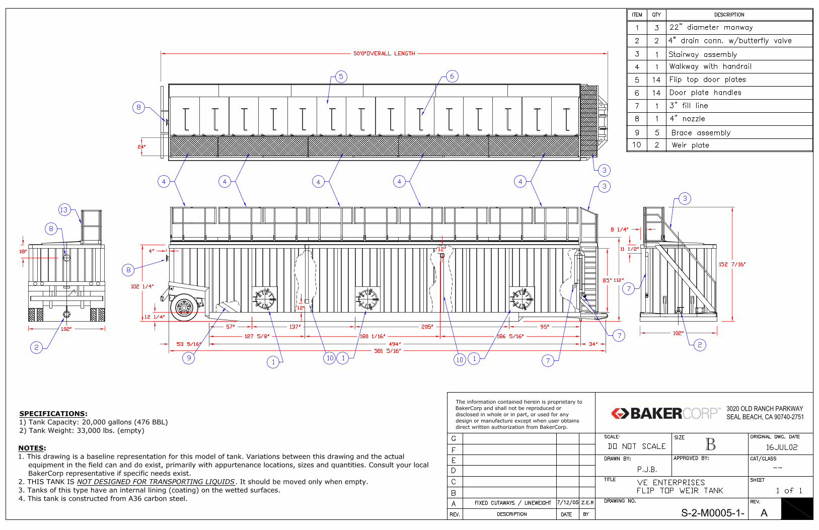

APPENDIX 2
Proposed Submersible Pump
Cut Sheet
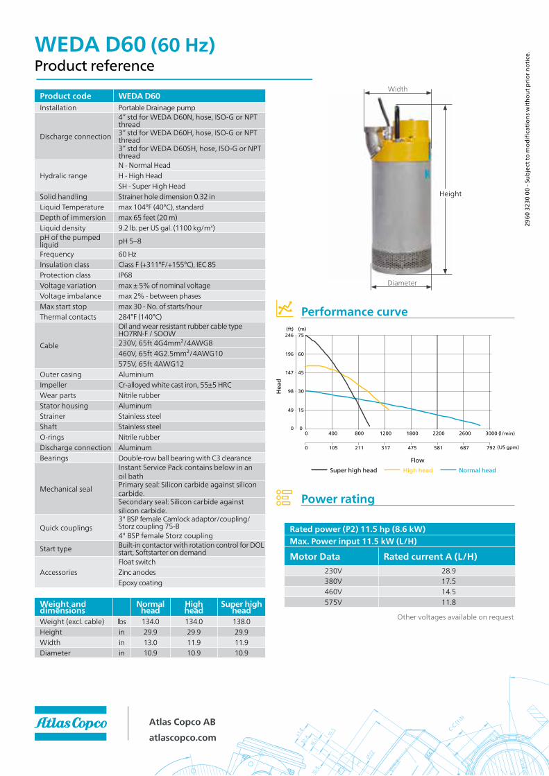
WEDA D60 (60 Hz)Product reference
Performance curve
2960
323
0 00
- Su
bjec
t to
mod
ifica
tions
wit
hout
prio
r not
ice.
Power rating
Product code WEDA D60Installation Portable Drainage pump
Discharge connection
4” std for WEDA D60N, hose, ISO-G or NPT thread3” std for WEDA D60H, hose, ISO-G or NPT thread3” std for WEDA D60SH, hose, ISO-G or NPT thread
Hydralic rangeN - Normal HeadH - High HeadSH - Super High Head
Solid handling Strainer hole dimension 0.32 inLiquid Temperature max 104°F (40°C), standardDepth of immersion max 65 feet (20 m)Liquid density 9.2 lb. per US gal. (1100 kg/m3)pH of the pumped liquid pH 5–8
Frequency 60 HzInsulation class Class F (+311°F/+155°C), IEC 85Protection class IP68Voltage variation max ± 5% of nominal voltageVoltage imbalance max 2% - between phasesMax start stop max 30 - No. of starts/hourThermal contacts 284°F (140°C)
Cable
Oil and wear resistant rubber cable type HO7RN-F / SOOW230V, 65ft 4G4mm²/4AWG8460V, 65ft 4G2.5mm²/4AWG10575V, 65ft 4AWG12
Outer casing AluminiumImpeller Cr-alloyed white cast iron, 55±5 HRCWear parts Nitrile rubberStator housing AluminumStrainer Stainless steelShaft Stainless steelO-rings Nitrile rubberDischarge connection AluminumBearings Double-row ball bearing with C3 clearance
Mechanical seal
Instant Service Pack contains below in an oil bathPrimary seal: Silicon carbide against silicon carbide.Secondary seal: Silicon carbide against silicon carbide.
Quick couplings3" BSP female Camlock adaptor/coupling/Storz coupling 75-B4" BSP female Storz coupling
Start type Built-in contactor with rotation control for DOL start, Softstarter on demand
AccessoriesFloat switchZinc anodesEpoxy coating
Weight anddimensions
Normalhead
High head
Super highhead
Weight (excl. cable) lbs 134.0 134.0 138.0Height in 29.9 29.9 29.9Width in 13.0 11.9 11.9Diameter in 10.9 10.9 10.9
Other voltages available on request
Rated power (P2) 11.5 hp (8.6 kW)Max. Power input 11.5 kW (L/H)
Motor Data Rated current A (L/H)230V 28.9380V 17.5460V 14.5575V 11.8
0
15
30
45
60
75
0
0 105 211
400 800 1200
317
1800 2200 2600
475
3000
581 687 792
(m)
(US gpm)
(l/min)
(ft)
0
49
196
246
147
98
Width
Diameter
Height
Hea
d
FlowSuper high head High head Normal head
Atlas Copco ABatlascopco.com

APPENDIX 3
Proposed Flow Meter
Cut Sheet
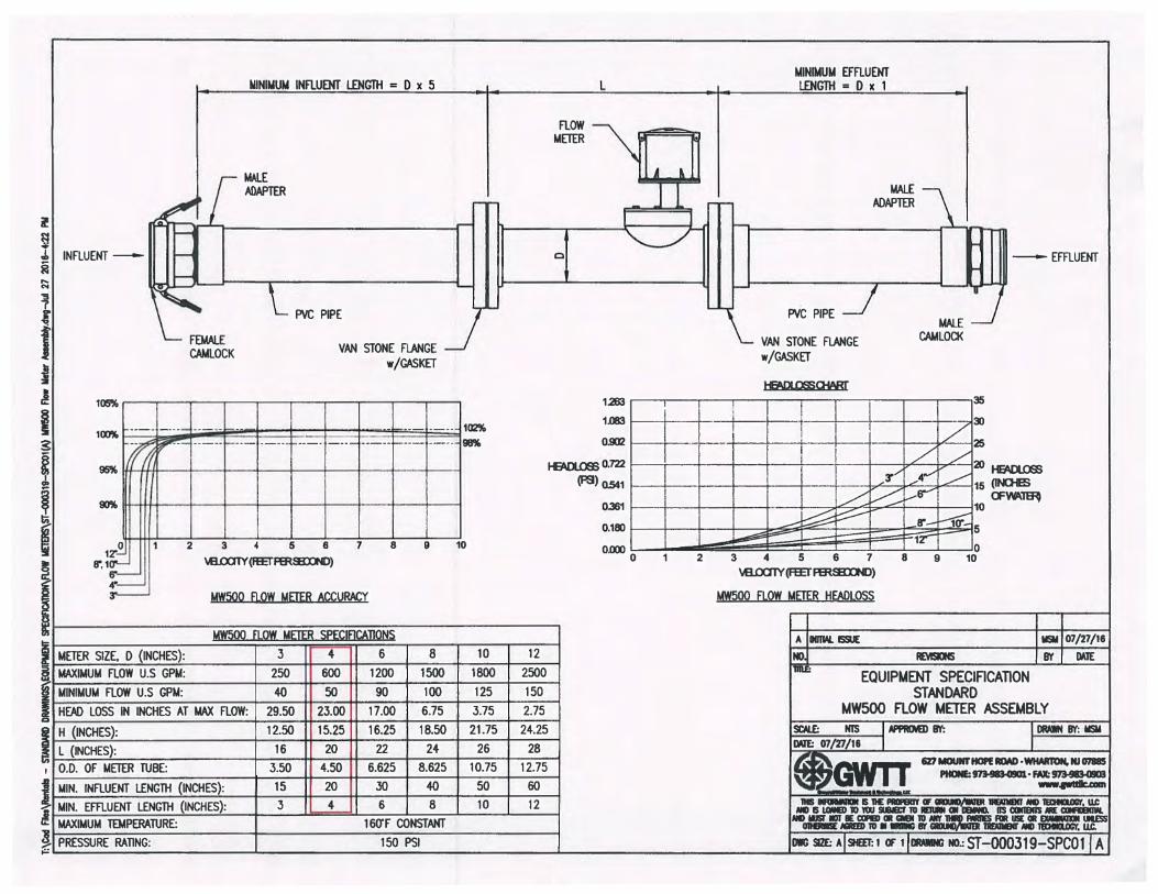

Attachment 4
Proposed Oil Water Separator
Cut Sheet
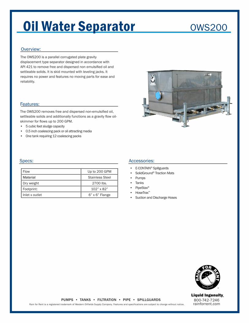
Oil Water Separator
Overview:
Features:
Specs:
The OWS200 is a parallel corrugated plate gravity
displacement type separator designed in accordance with
API 421 to remove free and dispersed non emulsified oil and settleable solids. It is skid mounted with leveling jacks. It
requires no power and features no moving parts for ease and
reliability.
The OWS200 removes free and dispersed non-emulsified oil, settleable solids and additionally functions as a gravity flow oil-skimmer for flows up to 200 GPM.• 5 cubic feet sludge capacity
• 0.5 inch coalescing pack or oil attracting media
• One tank requiring 12 coalescing packs
OWS200
Accessories:
• E-CONTAIN® Spillguards
• SolidGround® Traction Mats• Pumps
• Tanks
• PipeStax®
• HoseTrax™
• Suction and Discharge Hoses
Flow Up to 200 GPMMaterial Stainless Steel
Dry weight 2700 lbs.
Footprint: 102” x 82”
Inlet x outlet 6” x 6” Flange
800-742-7246rainforrent.com
PUMPS • TANKS • FILTRATION • PIPE • SPILLGUARDSRain for Rent is a registered trademark of Western Oilfields Supply Company. Features and specifications are subject to change without notice.

APPENDIX 5
Proposed Transfer Pump
Cut Sheet
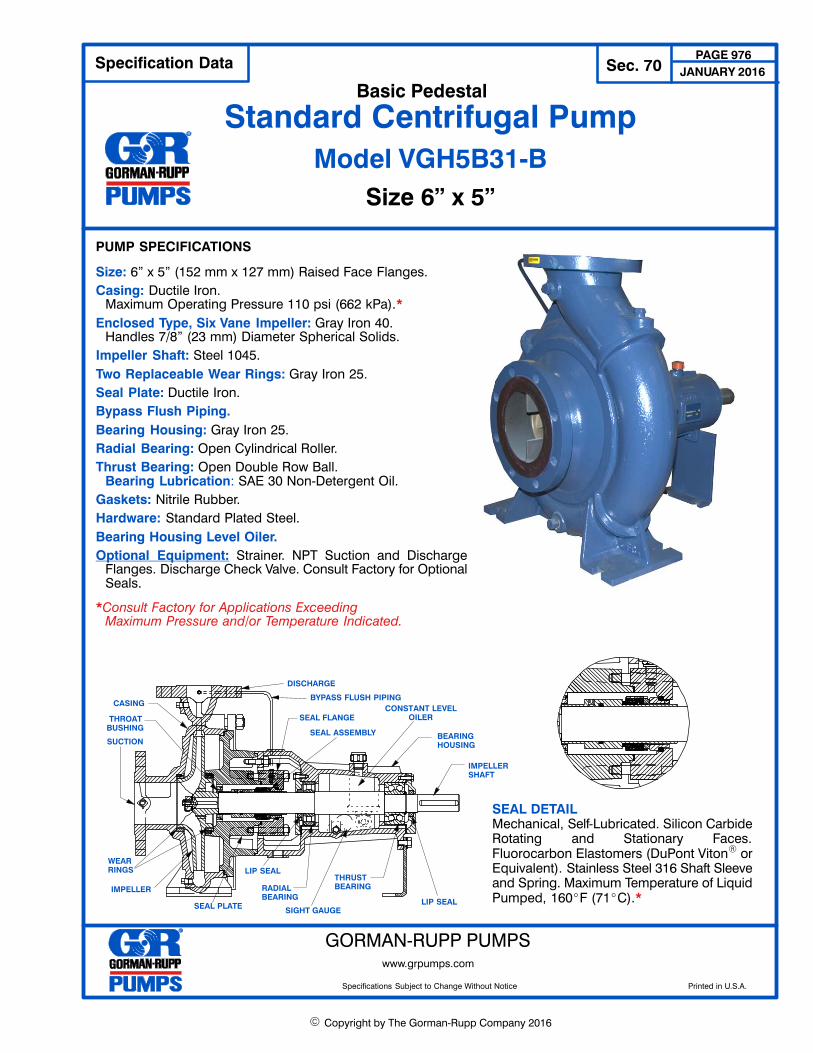
� Copyright by The Gorman‐Rupp Company 2016
Specification Data Sec. 70PAGE 976
Standard Centrifugal PumpBasic Pedestal
Model VGH5B31‐B
Size 6” x 5”
PUMP SPECIFICATIONS
Size: 6” x 5” (152 mm x 127 mm) Raised Face Flanges.
Casing: Ductile Iron.Maximum Operating Pressure 110 psi (662 kPa).*
Enclosed Type, Six Vane Impeller: Gray Iron 40. Handles 7/8” (23 mm) Diameter Spherical Solids.
Impeller Shaft: Steel 1045.
Two Replaceable Wear Rings: Gray Iron 25.
Seal Plate: Ductile Iron.
Bypass Flush Piping.
Bearing Housing: Gray Iron 25.
Radial Bearing: Open Cylindrical Roller.
Thrust Bearing: Open Double Row Ball.Bearing Lubrication: SAE 30 Non‐Detergent Oil.
Gaskets: Nitrile Rubber.
Hardware: Standard Plated Steel.
Bearing Housing Level Oiler.
Optional Equipment: Strainer. NPT Suction and DischargeFlanges. Discharge Check Valve. Consult Factory for OptionalSeals.
*Consult Factory for Applications ExceedingMaximum Pressure and/or Temperature Indicated.
SEAL DETAILMechanical, Self‐Lubricated. Silicon CarbideRotating and Stationary Faces.Fluorocarbon Elastomers (DuPont Viton� orEquivalent). Stainless Steel 316 Shaft Sleeveand Spring. Maximum Temperature of LiquidPumped, 160�F (71�C).*
DISCHARGE
SUCTION
CASING
SEAL PLATE
SEAL ASSEMBLY BEARINGHOUSING
IMPELLERSHAFT
RADIAL BEARING
IMPELLER
WEAR RINGS
THRUST BEARING
CONSTANT LEVELOILER
SIGHT GAUGE
BYPASS FLUSH PIPING
SEAL FLANGETHROATBUSHING
LIP SEAL
LIP SEAL
JANUARY 2016
GORMAN‐RUPP PUMPSwww.grpumps.com
Specifications Subject to Change Without Notice Printed in U.S.A.
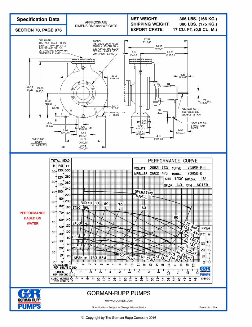
� Copyright by The Gorman‐Rupp Company 2016
Specification DataAPPROXIMATE
DIMENSIONS and WEIGHTS
SECTION 70, PAGE 976
NET WEIGHT: 366 LBS. (166 KG.)
SHIPPING WEIGHT: 386 LBS. (175 KG.)
EXPORT CRATE: 17 CU. FT. (0,5 CU. M.)
PERFORMANCE
BASED ON
WATER
GORMAN‐RUPP PUMPSwww.grpumps.com
Specifications Subject to Change Without Notice Printed in U.S.A.

APPENDIX 6
Proposed Bag Filter Housing
Cut Sheet
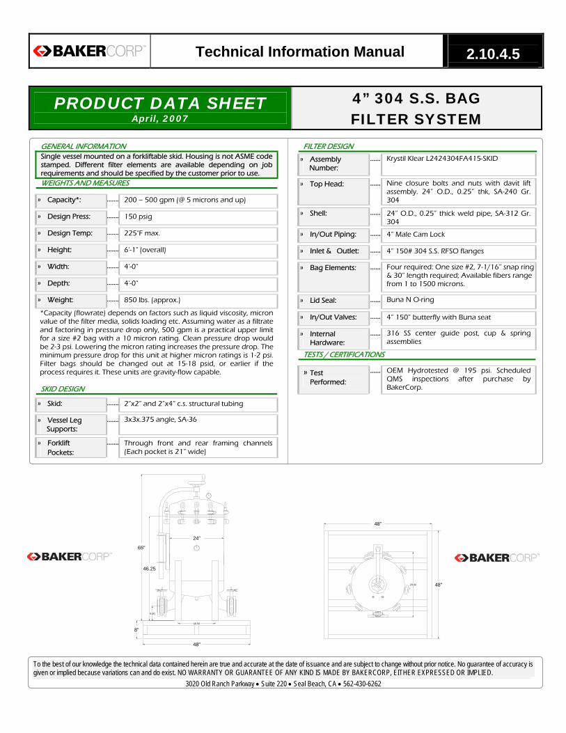
To the best of our knowledge the technical data contained herein are true and accurate at the date of issuance and are subject to change without prior notice. No guarantee of accuracy is given or implied because variations can and do exist. NO WARRANTY OR GUARANTEE OF ANY KIND IS MADE BY BAKERCORP, EITHER EXPRESSED OR IMPLIED.
3020 Old Ranch Parkway • Suite 220 • Seal Beach, CA • 562-430-6262
Technical Information Manual 2.10.4.5
PRODUCT DATA SHEET April, 2007
4” 304 S.S. BAG FILTER SYSTEM
GENERAL INFORMATION Single vessel mounted on a forkliftable skid. Housing is not ASME code stamped. Different filter elements are available depending on job requirements and should be specified by the customer prior to use. WEIGHTS AND MEASURES
» Capacity*: ....... 200 – 500 gpm (@ 5 microns and up)
» Design Press: ....... 150 psig
» Design Temp: ....... 225°F max.
» Height: ....... 6'-1" (overall)
» Width: ....... 4'-0"
» Depth: ....... 4'-0"
» Weight: ....... 850 lbs. (approx.)
*Capacity (flowrate) depends on factors such as liquid viscosity, micronvalue of the filter media, solids loading etc. Assuming water as a filtrateand factoring in pressure drop only, 500 gpm is a practical upper limitfor a size #2 bag with a 10 micron rating. Clean pressure drop wouldbe 2-3 psi. Lowering the micron rating increases the pressure drop. Theminimum pressure drop for this unit at higher micron ratings is 1-2 psi.Filter bags should be changed out at 15-18 psid, or earlier if theprocess requires it. These units are gravity-flow capable.
SKID DESIGN
» Skid: ....... 2”x2” and 2”x4” c.s. structural tubing
» Vessel LegSupports:
....... 3x3x.375 angle, SA-36
» ForkliftPockets:
....... Through front and rear framing channels (Each pocket is 21” wide)
FILTER DESIGN
» AssemblyNumber:
...... Krystil Klear L2424304FA415-SKID
» Top Head: ...... Nine closure bolts and nuts with davit lift assembly. 24” O.D., 0.25” thk, SA-240 Gr. 304
» Shell: ...... 24” O.D., 0.25” thick weld pipe, SA-312 Gr. 304
» In/Out Piping: ...... 4” Male Cam Lock
» Inlet & Outlet: ...... 4” 150# 304 S.S. RFSO flanges
» Bag Elements: ...... Four required: One size #2, 7-1/16” snap ring & 30” length required; Available fibers range from 1 to 1500 microns.
» Lid Seal: ...... Buna N O-ring
» In/Out Valves: ...... 4” 150” butterfly with Buna seat
» InternalHardware:
...... 316 SS center guide post, cup & spring assemblies
TESTS / CERTIFICATIONS
» TestPerformed:
...... OEM Hydrotested @ 195 psi. Scheduled QMS inspections after purchase by BakerCorp.
48"
8"
46.25
65"
24"
48"
48"
16.50
6.50
29.00
60
100
90
80
70
10
20
40
30
50
80
70
90
100
50
60
40
10
20
30

APPENDIX 7
Proposed LGAC
Vessel Cut Sheet

PV® SerieS HigH PreSSureLiquid PHaSe adSorPtion SyStemSPV®-5000SYS, PV®-10000SYS
Applications
The PV® Series Systems are designed for use in a wide range of low/high flow and pressure applications.
• Groundwaterremediation• Wastewaterfiltration• Tankrinsewatertreatment• Pilottesting• Undergroundstoragetankcleanup• Leachatetreatment• Dechlorination• Spillcleanup• Hydrotesting• DrinkingWater
Installation, Startup and Operation
EvoquacanprovideatotalservicepackagethatincludesutilizingOSHAtrainedpersonnelprovidingon-sitecarbonchangeouts,packagingandtransportationofspentcarbonforrecyclingatourRCRApermittedreactivationfacilities.
Atthetimeofpurchaseorrentaloftheadsorbers,arrang-mentsshouldbemadeforthereactivationofthespentcarbon.Evoqua will provide instructions and assistance on how to obtainacceptanceofthespentcarbonatourreactivationfacilities.Spentcarboncannotbeacceptedforreactivationuntil the acceptance process is completed.
Benefits & Design Features
• SSPC-SP5,NSF-approvedepoxylining,rustpreventativeepoxyprimerurethaneexteriorfinish.
• Topandsidemanwayspermiteasyaccessandinspection of vessels internals and linings.
• Skid-mountedforeasyhandlingandinstallation.• Optimizedunderdrainsystemforlowpressure
drop operation.• Pipingmanifoldallowseitheradsorbertobeused
in the lead or lag position.• Seriesorparalleloperation.• PV-5000SYSSystemsareshippedcompletewith
facepipingassembledandGACloaded;noon-siteassemblyisrequired.
• PV-10000SYSSystemsrequireGACtransferviaslurrypiping(4”Sch10304LSS).
181ThornHillRoad,Warrendale,PA15086
+1 (866) 926-8420(toll-free) +1 (978) 614-7233(toll) www.evoqua.com
PVandHParetrademarksofEvoqua,itssubsidiariesoraffiliates,insomecountries.
Allinformationpresentedhereinisbelievedreliableandinaccordancewithacceptedengineeringpractices.Evoquamakesnowarrantiesastothecompletenessofthisinformation.Usersareresponsibleforevaluatingindividualproductsuitabilityforspecificapplications.Evoquaassumesnoliabilitywhatsoeverforanyspecial,indirectorconsequentialdamagesarisingfromthesale, resale or misuse of its products.
©2015EvoquaWaterTechnologiesLLC Subjecttochangewithoutnotice WS-PV1-DS-0815
Safety Note:Wetactivatedcarbonreadilyadsorbsatmosphericoxygen.Dangerouslylowoxygenlevelsmayexistinclosedvesselsorpoorlyventilatedstorageareas.Workersshouldfollowallapplicablestateandfederalsafetyguidelinesforenteringoxygendepletedareas.
Allinformationpresentedhereinisbelievedreliableandinaccordancewithacceptedengineeringpractices.Evoquamakesnowarrantiesastocompletenessofinformation.Usersareresponsibleforevaluatingindividualproductsuitabilityforspecificapplications.Evoquaassumesnoliabilitywhatsoeverfor any special, indirect or consequential damages arising from the sale, resale or misuse of its products.
SPecificationSPV®-5000SYS PV®-10000
Dimensions(VesselDia.xOverallHeight–Approx.) 72”x11’4” 96”x15’2”
Footprint(LengthxWidth) 14’2”x8’ 22’8”x10’
InletConnection(Top) 4” 6”
OutletConnection(Bottom) 4” 6”
Manway,Top&LowerSide (2)14”x18” 14”x18”/20”
Internal Piping 304LSS 304LSS
InteriorCoating(AllUnits) Epoxy Epoxy
ExteriorCoating(AllUnits) Epoxy/Urethane Epoxy/Urethane
VesselWeight(lbs.): Shipping(Skid) Operating(Approx.)
18,000(Twovessels,piping,carbon)34,600
15,500(Twovessels,piping)85,000
Flow,GPM(NominalPerVessel) 250 500
Pressure,PSIG(Maximum)1 75 75
Temperature,°F(Maximum) 140 140
PoundsOfCarbon(PerVessel) 5,000 10,000
BackwashRate,GPM(8x30Mesh@55°F) 250 450
1ThePV®SeriesadsorbersarenotASMEcodestamped.Pressureratingappliestoliquidonly.Fordetaileddimensionalinformationordrawings,contactyourlocalEvoquasalesrepresentative.ForinformationontheHP®SeriesASMEcodestampedadsorbers,contactyourlocalEvoquarepresentative.
0.0
1.0
2.0
3.0
4.0
5.0
6.0
7.0
8.0
9.0
0 100 200 300 400 500
PV®-10000SYSPV®-5000SYS
Pres
sure
Dro
p PS
I
Flow GPM
PV® Series Pressure Drop (Series Operation)

APPENDIX 8
Proposed Cartridge Filter
Housing Cut Sheet

To the best of our knowledge the technical data contained herein are true and accurate at the date of issuance and are subject to change without prior notice. No guarantee of accuracy is given or implied because variations can and do exist. NO WARRANTY OR GUARANTEE OF ANY KIND IS MADE BY BAKERCORP, EITHER EXPRESSED OR IMPLIED.
3020 Old Ranch Parkway • Suite 220 • Seal Beach, CA • 562-430-6262
Technical Information Manual 2.10.1
PRODUCT DATA SHEET August, 2008
DUPLEX CARTRIDGE FILTER SYSTEM
GENERAL INFORMATION Two independent filters are trailer mounted and piped such that one filter unit is active while the other is out of service. Inlet and outlet connections are provided on each end of the trailer. Housings are not ASME code stamped. WEIGHTS AND MEASURES
» Capacity: ....... 600 gpm nominal flow rate
» Design Press: ....... 150 psig
» Design Temp: ....... 400°F max.
» Height: ....... 2'-4" (deck height) 8'-5" (overall)
» Width : ....... 7'-0"
» Length: ....... 15'-0"
» Weight: ....... 1,981 lbs.
TRAILER DESIGN
» Trailer Body: ....... 2"x 12" channel
» Sub-frame: ....... 3"x 3" structural tubing
» Trailer Deck: ....... 3/16" thick diamond plate
» Wheels: ....... Eight spokes, 14x6
» Tires: ....... ST205/75D14, 50 psi inflation pressure
» Pintle Hook: ....... Wallace Forge part # AR3-048, 20,000 lbs. gross trailer weight, 1000 lb. max. vertical load
» Axles: ....... Tandem 3,500#
» Brakes: ....... Dexter 10"x2¼", with Raybestos breakaway kit including emergency battery
» Lights: ....... Side marker lighting and tail lights
» Jacks: ....... One permanent lifting jack on tongue, and one jack for each trailer corner
FILTER DESIGN
» Filter Housing ....... Two Rosedale 304 S.S. Model 24-40-40-4F-2-150-SST-B-VP housings, duplex arrangement, Buna N gasket, 4" 150# RFSO flanged inlet, 4" 150# RFSO flanged outlet
» Filter Access: ....... Domed lid with (8) swing-bolt closure assemblies, davit arm assembly for removal, Buna N o-ring sealed
» Piping: ....... Schedule 80 PVC, design MAWP of 150 psig at ambient temperature
» Inlet & Outlet: ....... Six-inch header with connections at each end of trailer; one end is blinded with 150# blind flange. Branch line from header to filters is four-inch.
» Cartridges: ....... 40" length double open-end style. 40 total required. (Five micron – 200 micron filtration available)
» Inlet Baffle: ....... 14"x14"x½" 316 SS plate
» DifferentialPress. Gauge:
....... 0-30 in. water, 2½" dial case, ¼" NPT ports,Buna N static seals, aluminum wettedparts, teflon piston seal
» ButterflyValves:
....... 125 WB/LB , 200 psig MAWP, ductile iron body & disc, 416 SS shaft, Buna N seat and seal
» Ball Valves: ....... 1" PVC, rated for 150# @ 73°F.
» Vent Valves: ....... ½" steel ball valves, one on each filter housing
» Drain Valves: ....... No-Kink hose bibbs, ¾"MIPx¾" hose
» Pipe: ....... Schedule 80 PVC
SURFACE DETAILS
» ExteriorCoating:
....... High Gloss Polyurethane
TESTS / CERTIFICATIONS
» TestPerformed:
....... Scheduled QMS inspections

ATTACHMENT 9
SAMPLE LANDFILL PERMIT PLANS

PROPOSED LANDFILLDISTURBANCE AREA
OVERVIEW
SAMPLE
NOT FOR
CONSTRUCTION

LANDFILLEXCAVATION PLAN
SAMPLE
NOT FOR
CONSTRUCTION

X
X
X
X
X
X
X
X
X
X
X
X
X
X
X
X
X
X
X
X
X
X
X
X
X
X
X
X
X
X
X
X
X
X
X
X
X
X
X
X
X
X
X
X
X
X
X
X
X
X
X
X
X
X
X
X
X
X
X
X
X
X
X
X
X
X
X
X
X
X
X
X
X
X
X
X
X
X
X
X
X
XX
X
X
X
X
X
X
X
X
X
X
X
X
X
X
X
X
X
X
X
X
X
X
X
X
X
X
X X
X
X
X
X
X
X
LANDFILLEXCAVATION PLAN
- PROFILES ANDSECTIONS
0 52.55
VERTICAL SCALE: 1"=5'
05 1010
HORIZONTAL SCALE: 1"=10'
0 31.53
VERTICAL SCALE: 1"=3'
05 1010
HORIZONTAL SCALE: 1"=10'
SAMPLE
NOT FOR
CONSTRUCTION

LANDFILLRESTORATION PLAN
SAMPLE
NOT FOR
CONSTRUCTION

X
X
X
X
X
X
X
X
X
X
X
X
XX
X
X
X
X
X
X
X
X
X
X
X
X
XX
X
X
X
X
X
X
X
X
X
X
X
X
XX
CONSTRUCTIONNOTES & DETAILS
SAMPLE
NOT FOR
CONSTRUCTION