Embed Size (px)
Citation preview
R8.0
TECHNICAL REFERENCE
- EtherCAT Communication Specification -
MODEL
Product Name: AC Servo Driver Product No.: MINAS-A6BL series (EtherCAT communication、Linear/DD type)
Issued on Jun.14, 2018
Revised on Dec. 1, 2021
Motion Control Business Unit, Industrial Device Business Division
Industry Company, Panasonic Corporation 7-1-1 Morofuku, Daito-City, Osaka 574-0044, Japan
Phone: +81-72-871-1212 Fax : +81-72-870-3151
No. SX-DSV03307
No.SX-DSV03307
R8.0 Motion Control Business Unit, Panasonic Corporation
この英文仕様書は、原本である和文仕様書を元にパナソニック株式会社インダストリー社
産業デバイス事業部モーションコントロールビジネスユニットが翻訳・発行するものです。
翻訳は,原本の利用に際して一応の参考となるように便宜的に仮訳したものであり、公的
な校閲を受けたものではありません。英語訳のみを使用して生じた不都合な事態に関して
は,当社は一切責任を負うものではありません。和文仕様書のみが有効です。 パナソニック株式会社
インダストリー社 産業デバイス事業部 モーションコントロールビジネスユニット
This English specification is made and published by Motion Control Business Unit, Industrial Device Business Division, Industry Company, Panasonic Corporation based on the original Japanese specification. Translation is provided unofficially only for the sake of convenience of utilizing the original Japanese specification as a measure of reference. It is not officially reviewed. Motion Control Business Unit, Industrial Device Business Division, Industry Company, Panasonic Corporation is not liable for any disadvantages caused by utilizing only English specification. Only the Japanese specification is effective.
Motion Control Business Unit, Industrial Device Business Division, Industry Company, Panasonic Corporation
No.SX-DSV03307
R8.0 Motion Control Business Unit, Panasonic Corporation
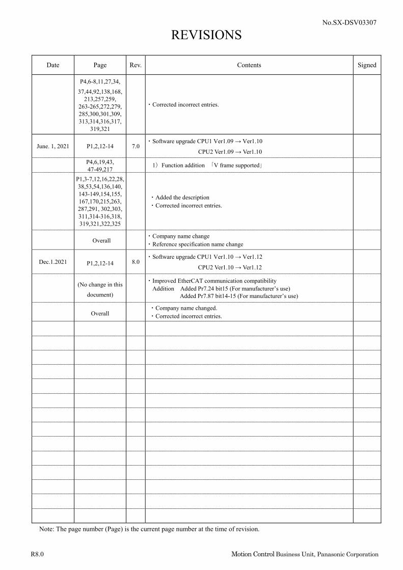
REVISIONS
Date Page Rev. Contents Signed
Jun.14, 2018 - 1.0 First edition
Oct.26, 2018 P1,2,3 2.0 Software upgrade CPU1 Ver1.04 → Ver1.05 CPU2 Ver1.04 → Ver1.05
P1,3,76 1) Function addition “Retracting operation function”
P3,86-90,102, 103,117,118,
128,129, 154-157,
162,163,172, 173,179,180, 181,186,187, 194,195,301,
319
2) Function addition “Dealing with EtherCAT object extension”
・Extension of torque limit function ・Extension of velocity limit function under torque control
P5,6 ・addition Added explanation about ESI
Mar.20, 2019 P1,2,3,10-12 3.0 Software upgrade CPU1 Ver1.05 → Ver1.06 CPU2 Ver1.05→ Ver1.06
P306 1) Function addition “Torque monitor value accuracy improvement”
Apr.30, 2019 P1,2,3,10-12 4.0 Software upgrade CPU1 Ver1.06 → Ver1.07 CPU2 Ver1.06→ Ver1.07
P10,17,59,60, 63,65,67,269 1) Function addition “EtherCAT communication cycle 8ms, 10ms extension”
P49,93,98, 140-151,157, 159,161,179,
183,185,200,222, 237,242,253,287,
306
・Added the description ・Corrected incorrect entries.
Overall ・Company name changed.
May.12, 2020 P1-3,11-13 5.0 ・Software upgrade CPU1 Ver1.07 → Ver1.08 CPU2 Ver1.07 → Ver1.08
P36,229,265, 289,312 1) Function addition “Specification extension of over-travel inhibition input”
P6,7,217 ・Added notes
Sep.14, 2020 P1-3,11-13 6.0 ・Software upgrade CPU1 Ver1.08 → Ver1.09
CPU2 Ver1.08 → Ver1.09
P197,199 1) Function addition “Velocity limit priority function during torque control”
P203,206-207,
210-211, 313,317
2) Function addition “Specification extension of Touch Probe function”
P95,98,319 3) Function addition “Target position echo function”
Note: The page number (Page) is the current page number at the time of revision.
No.SX-DSV03307
R8.0 Motion Control Business Unit, Panasonic Corporation
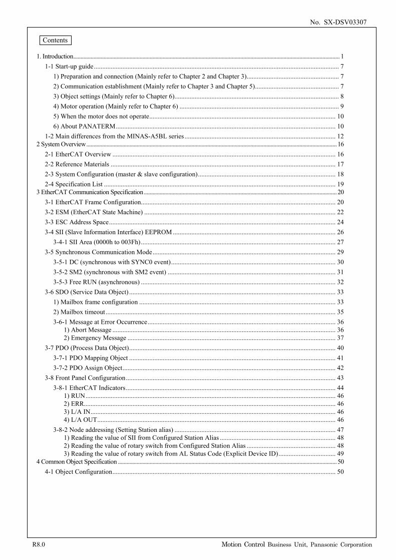
REVISIONS
Date Page Rev. Contents Signed
P4,6-8,11,27,34,
37,44,92,138,168, 213,257,259,
263-265,272,279, 285,300,301,309, 313,314,316,317,
319,321
・Corrected incorrect entries.
June. 1, 2021 P1,2,12-14 7.0 ・Software upgrade CPU1 Ver1.09 → Ver1.10
CPU2 Ver1.09 → Ver1.10
P4,6,19,43, 47-49,217 1)Function addition 「V frame supported」
P1,3-7,12,16,22,28, 38,53,54,136,140, 143-149,154,155, 167,170,215,263, 287,291, 302,303, 311,314-316,318, 319,321,322,325
・Added the description ・Corrected incorrect entries.
Overall ・Company name change ・Reference specification name change
Dec.1.2021 P1,2,12-14 8.0 ・Software upgrade CPU1 Ver1.10 → Ver1.12
CPU2 Ver1.10 → Ver1.12
(No change in this
document)
・Improved EtherCAT communication compatibility Addition Added Pr7.24 bit15 (For manufacturer’s use)
Added Pr7.87 bit14-15 (For manufacturer’s use)
Overall ・Company name changed. ・Corrected incorrect entries.
Note: The page number (Page) is the current page number at the time of revision.
No. SX-DSV03307
R8.0 Motion Control Business Unit, Panasonic Corporation
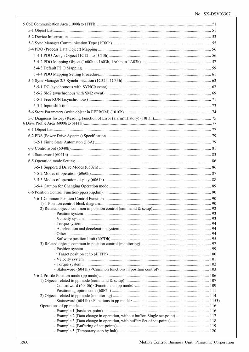
Contents
1. Introduction ......................................................................................................................................................................................... 1
1-1 Start-up guide .................................................................................................................................................. 7 1) Preparation and connection (Mainly refer to Chapter 2 and Chapter 3) ....................................................... 7 2) Communication establishment (Mainly refer to Chapter 3 and Chapter 5) .................................................. 7 3) Object settings (Mainly refer to Chapter 6) .................................................................................................. 8 4) Motor operation (Mainly refer to Chapter 6) ............................................................................................... 9 5) When the motor does not operate ............................................................................................................... 10 6) About PANATERM ................................................................................................................................... 10
1-2 Main differences from the MINAS-A5BL series .......................................................................................... 12 2 System Overview .............................................................................................................................................................................. 16
2-1 EtherCAT Overview ..................................................................................................................................... 16 2-2 Reference Materials ...................................................................................................................................... 17 2-3 System Configuration (master & slave configuration) .................................................................................. 18 2-4 Specification List .......................................................................................................................................... 19
3 EtherCAT Communication Specification ...................................................................................................................................... 20 3-1 EtherCAT Frame Configuration .................................................................................................................... 20 3-2 ESM (EtherCAT State Machine) .................................................................................................................. 22 3-3 ESC Address Space ....................................................................................................................................... 24 3-4 SII (Slave Information Interface) EEPROM ................................................................................................. 26
3-4-1 SII Area (0000h to 003Fh) .................................................................................................................... 27 3-5 Synchronous Communication Mode ............................................................................................................. 29
3-5-1 DC (synchronous with SYNC0 event) .................................................................................................. 30 3-5-2 SM2 (synchronous with SM2 event) .................................................................................................... 31 3-5-3 Free RUN (asynchronous) .................................................................................................................... 32
3-6 SDO (Service Data Object) ........................................................................................................................... 33 1) Mailbox frame configuration ..................................................................................................................... 33 2) Mailbox timeout ......................................................................................................................................... 35 3-6-1 Message at Error Occurrence ................................................................................................................ 36
1) Abort Message ..................................................................................................................................... 36 2) Emergency Message ............................................................................................................................ 37
3-7 PDO (Process Data Object) ........................................................................................................................... 40 3-7-1 PDO Mapping Object ........................................................................................................................... 41 3-7-2 PDO Assign Object ............................................................................................................................... 42
3-8 Front Panel Configuration ............................................................................................................................. 43 3-8-1 EtherCAT Indicators ............................................................................................................................. 44
1) RUN ..................................................................................................................................................... 46 2) ERR...................................................................................................................................................... 46 3) L/A IN .................................................................................................................................................. 46 4) L/A OUT .............................................................................................................................................. 46
3-8-2 Node addressing (Setting Station alias) ................................................................................................ 47 1) Reading the value of SII from Configured Station Alias ..................................................................... 48 2) Reading the value of rotary switch from Configured Station Alias ..................................................... 48 3) Reading the value of rotary switch from AL Status Code (Explicit Device ID) .................................. 49
4 Common Object Specification ........................................................................................................................................................ 50 4-1 Object Configuration ..................................................................................................................................... 50
No. SX-DSV03307
R8.0 Motion Control Business Unit, Panasonic Corporation
5 CoE Communication Area (1000h to 1FFFh) ............................................................................................................................... 51
5-1 Object List ..................................................................................................................................................... 51 5-2 Device Information ....................................................................................................................................... 53 5-3 Sync Manager Communication Type (1C00h).............................................................................................. 55 5-4 PDO (Process Data Object) Mapping ........................................................................................................... 56
5-4-1 PDO Assign Object (1C12h to 1C13h) ................................................................................................. 56 5-4-2 PDO Mapping Object (1600h to 1603h, 1A00h to 1A03h) .................................................................. 57 5-4-3 Default PDO Mapping .......................................................................................................................... 59 5-4-4 PDO Mapping Setting Procedure .......................................................................................................... 61
5-5 Sync Manager 2/3 Synchronization (1C32h, 1C33h) .................................................................................... 63 5-5-1 DC (synchronous with SYNC0 event) .................................................................................................. 67 5-5-2 SM2 (synchronous with SM2 event) .................................................................................................... 69 5-5-3 Free RUN (asynchronous) .................................................................................................................... 71 5-5-4 Input shift time ...................................................................................................................................... 73
5-6 Store Parameters (write object in EEPROM) (1010h) .................................................................................. 74 5-7 Diagnosis history (Reading Function of Error (alarm) History) (10F3h) ...................................................... 75
6 Drive Profile Area (6000h to 6FFFh) ............................................................................................................................................. 77 6-1 Object List ..................................................................................................................................................... 77 6-2 PDS (Power Drive Systems) Specification ................................................................................................... 79
6-2-1 Finite State Automaton (FSA) .............................................................................................................. 79 6-3 Controlword (6040h) ..................................................................................................................................... 81 6-4 Statusword (6041h) ....................................................................................................................................... 83 6-5 Operation mode Setting ................................................................................................................................. 86
6-5-1 Supported Drive Modes (6502h) .......................................................................................................... 86 6-5-2 Modes of operation (6060h).................................................................................................................. 87 6-5-3 Modes of operation display (6061h) ..................................................................................................... 88 6-5-4 Caution for Changing Operation mode ................................................................................................. 89
6-6 Position Control Function(pp,csp,ip,hm) ...................................................................................................... 90 6-6-1 Common Position Control Function ..................................................................................................... 90
1)-1 Position control block diagram ......................................................................................................... 90 2) Related objects common in position control (command & setup) ....................................................... 92
3) Related objects common in position control (monitoring) ................................................................... 97
6-6-2 Profile Position mode (pp mode) ........................................................................................................ 106 1) Objects related to pp mode (command & setup) ................................................................................ 107
2) Objects related to pp mode (monitoring) ........................................................................................... 114 3)
Operations of pp mode ........................................................................................................................... 116
- Position system ......................................................................................................................... 93 - Velocity system ........................................................................................................................ 93 - Torque system .......................................................................................................................... 94 - Acceleration and deceleration system ...................................................................................... 94 - Other ......................................................................................................................................... 94 - Software position limit (607Dh) ............................................................................................... 95
- Position system ......................................................................................................................... 99 ・Target position echo (4FFFh) ............................................................................................... 100 - Velocity system ...................................................................................................................... 101 - Torque system ........................................................................................................................ 102 - Statusword (6041h) <Common functions in position control> .............................................. 103
- Controlword (6040h) <Functions in pp mode> ...................................................................... 109 - Positioning option code (60F2h) ............................................................................................ 111
- Statusword (6041h) <Functions in pp mode> ........................................................................ 115
- Example 1 (basic set-point) .................................................................................................... 116 - Example 2 (Data change in operation, without buffer: Single set-point) ............................... 117 - Example 3 (Data change in operation, with buffer: Set of set-points) .................................... 118 - Example 4 (Buffering of set-points) ....................................................................................... 119 - Example 5 (Temporary stop by halt) ...................................................................................... 120
No. SX-DSV03307
R8.0 Motion Control Business Unit, Panasonic Corporation
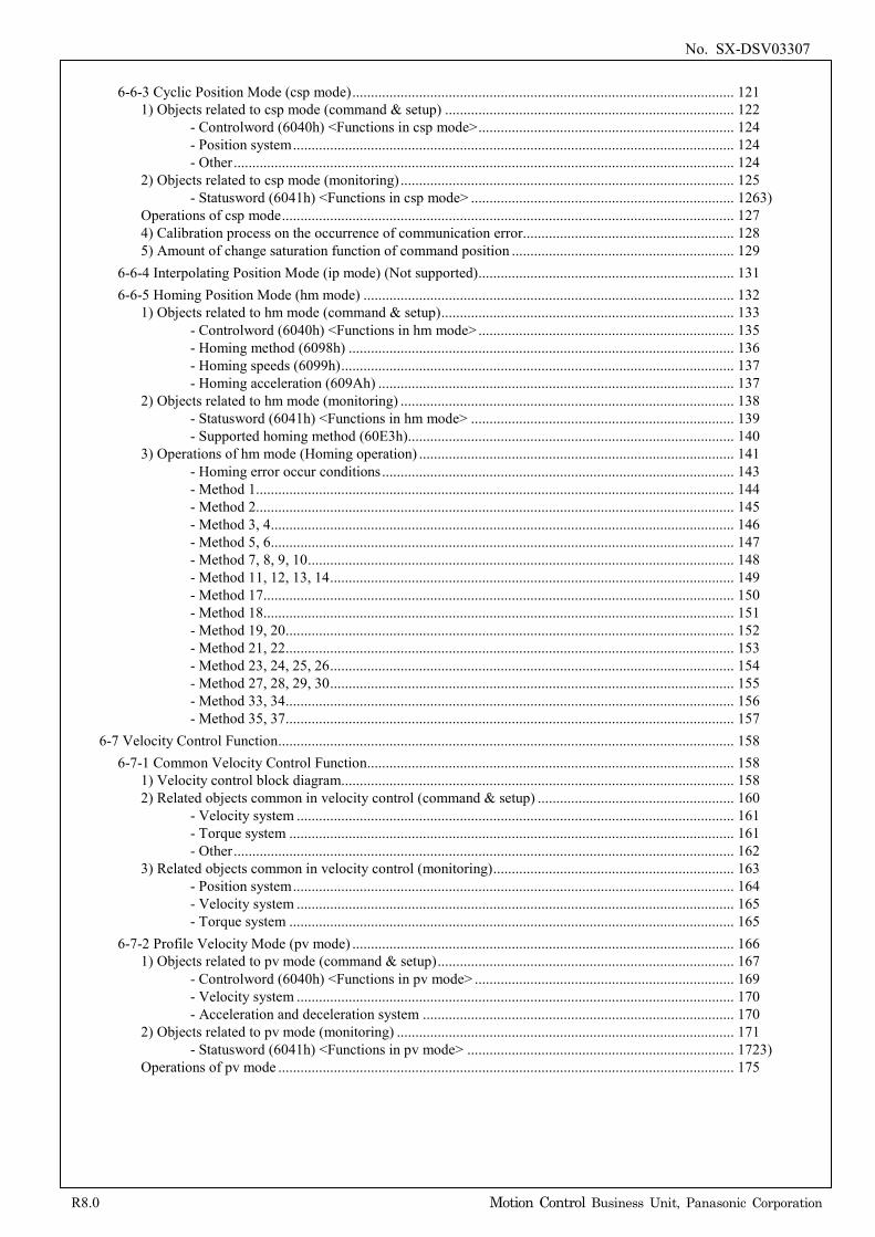
6-6-3 Cyclic Position Mode (csp mode) ....................................................................................................... 121
1) Objects related to csp mode (command & setup) .............................................................................. 122
2) Objects related to csp mode (monitoring) .......................................................................................... 125 3)
Operations of csp mode .......................................................................................................................... 127 4) Calibration process on the occurrence of communication error ......................................................... 128 5) Amount of change saturation function of command position ............................................................ 129
6-6-4 Interpolating Position Mode (ip mode) (Not supported) ..................................................................... 131 6-6-5 Homing Position Mode (hm mode) .................................................................................................... 132
1) Objects related to hm mode (command & setup) ............................................................................... 133
2) Objects related to hm mode (monitoring) .......................................................................................... 138
3) Operations of hm mode (Homing operation) ..................................................................................... 141
6-7 Velocity Control Function ........................................................................................................................... 158 6-7-1 Common Velocity Control Function................................................................................................... 158
1) Velocity control block diagram.......................................................................................................... 158 2) Related objects common in velocity control (command & setup) ..................................................... 160
3) Related objects common in velocity control (monitoring) ................................................................. 163
6-7-2 Profile Velocity Mode (pv mode) ....................................................................................................... 166 1) Objects related to pv mode (command & setup) ................................................................................ 167
2) Objects related to pv mode (monitoring) ........................................................................................... 171 3)
Operations of pv mode ........................................................................................................................... 175
- Controlword (6040h) <Functions in csp mode> ..................................................................... 124 - Position system ....................................................................................................................... 124 - Other ....................................................................................................................................... 124
- Statusword (6041h) <Functions in csp mode> ....................................................................... 126
- Controlword (6040h) <Functions in hm mode> ..................................................................... 135 - Homing method (6098h) ........................................................................................................ 136 - Homing speeds (6099h) .......................................................................................................... 137 - Homing acceleration (609Ah) ................................................................................................ 137
- Statusword (6041h) <Functions in hm mode> ....................................................................... 139 - Supported homing method (60E3h) ........................................................................................ 140
- Homing error occur conditions ............................................................................................... 143 - Method 1 ................................................................................................................................. 144 - Method 2 ................................................................................................................................. 145 - Method 3, 4 ............................................................................................................................. 146 - Method 5, 6 ............................................................................................................................. 147 - Method 7, 8, 9, 10 ................................................................................................................... 148 - Method 11, 12, 13, 14 ............................................................................................................. 149 - Method 17 ............................................................................................................................... 150 - Method 18 ............................................................................................................................... 151 - Method 19, 20 ......................................................................................................................... 152 - Method 21, 22 ......................................................................................................................... 153 - Method 23, 24, 25, 26 ............................................................................................................. 154 - Method 27, 28, 29, 30 ............................................................................................................. 155 - Method 33, 34 ......................................................................................................................... 156 - Method 35, 37 ......................................................................................................................... 157
- Velocity system ...................................................................................................................... 161 - Torque system ........................................................................................................................ 161 - Other ....................................................................................................................................... 162
- Position system ....................................................................................................................... 164 - Velocity system ...................................................................................................................... 165 - Torque system ........................................................................................................................ 165
- Controlword (6040h) <Functions in pv mode> ...................................................................... 169 - Velocity system ...................................................................................................................... 170 - Acceleration and deceleration system .................................................................................... 170
- Statusword (6041h) <Functions in pv mode> ........................................................................ 172
No. SX-DSV03307
R8.0 Motion Control Business Unit, Panasonic Corporation
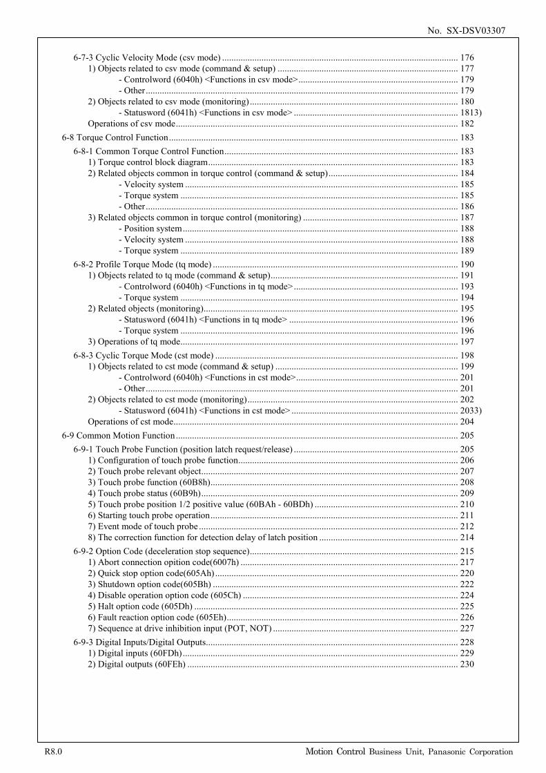
6-7-3 Cyclic Velocity Mode (csv mode) ...................................................................................................... 176
1) Objects related to csv mode (command & setup) .............................................................................. 177
2) Objects related to csv mode (monitoring) .......................................................................................... 180 3)
Operations of csv mode .......................................................................................................................... 182 6-8 Torque Control Function ............................................................................................................................. 183
6-8-1 Common Torque Control Function ..................................................................................................... 183 1) Torque control block diagram ............................................................................................................ 183 2) Related objects common in torque control (command & setup) ........................................................ 184
3) Related objects common in torque control (monitoring) ................................................................... 187
6-8-2 Profile Torque Mode (tq mode) .......................................................................................................... 190 1) Objects related to tq mode (command & setup) ................................................................................. 191
2) Related objects (monitoring) .............................................................................................................. 195
3) Operations of tq mode ........................................................................................................................ 197 6-8-3 Cyclic Torque Mode (cst mode) ......................................................................................................... 198
1) Objects related to cst mode (command & setup) ............................................................................... 199
2) Objects related to cst mode (monitoring) ........................................................................................... 202 3)
Operations of cst mode ........................................................................................................................... 204 6-9 Common Motion Function .......................................................................................................................... 205
6-9-1 Touch Probe Function (position latch request/release) ....................................................................... 205 1) Configuration of touch probe function ............................................................................................... 206 2) Touch probe relevant object ............................................................................................................... 207 3) Touch probe function (60B8h) ........................................................................................................... 208 4) Touch probe status (60B9h) ............................................................................................................... 209 5) Touch probe position 1/2 positive value (60BAh - 60BDh) .............................................................. 210 6) Starting touch probe operation ........................................................................................................... 211 7) Event mode of touch probe ................................................................................................................ 212 8) The correction function for detection delay of latch position ............................................................ 214
6-9-2 Option Code (deceleration stop sequence) .......................................................................................... 215 1) Abort connection opition code(6007h) .............................................................................................. 217 2) Quick stop option code(605Ah) ......................................................................................................... 220 3) Shutdown option code(605Bh) .......................................................................................................... 222 4) Disable operation option code (605Ch) ............................................................................................. 224 5) Halt option code (605Dh) .................................................................................................................. 225 6) Fault reaction option code (605Eh) .................................................................................................... 226 7) Sequence at drive inhibition input (POT, NOT) ................................................................................ 227
6-9-3 Digital Inputs/Digital Outputs............................................................................................................. 228 1) Digital inputs (60FDh) ....................................................................................................................... 229 2) Digital outputs (60FEh) ..................................................................................................................... 230
- Controlword (6040h) <Functions in csv mode> ..................................................................... 179 - Other ....................................................................................................................................... 179
- Statusword (6041h) <Functions in csv mode> ....................................................................... 181
- Velocity system ...................................................................................................................... 185 - Torque system ........................................................................................................................ 185 - Other ....................................................................................................................................... 186
- Position system ....................................................................................................................... 188 - Velocity system ...................................................................................................................... 188 - Torque system ........................................................................................................................ 189
- Controlword (6040h) <Functions in tq mode> ....................................................................... 193 - Torque system ........................................................................................................................ 194
- Statusword (6041h) <Functions in tq mode> ......................................................................... 196 - Torque system ........................................................................................................................ 196
- Controlword (6040h) <Functions in cst mode> ...................................................................... 201 - Other ....................................................................................................................................... 201
- Statusword (6041h) <Functions in cst mode> ........................................................................ 203
No. SX-DSV03307
R8.0 Motion Control Business Unit, Panasonic Corporation
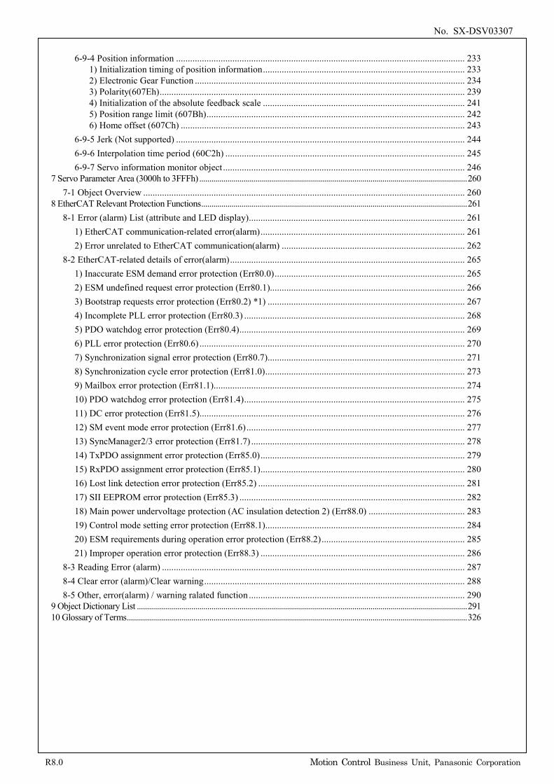
6-9-4 Position information ........................................................................................................................... 233
1) Initialization timing of position information ...................................................................................... 233 2) Electronic Gear Function ................................................................................................................... 234 3) Polarity(607Eh) .................................................................................................................................. 239 4) Initialization of the absolute feedback scale ...................................................................................... 241 5) Position range limit (607Bh) .............................................................................................................. 242 6) Home offset (607Ch) ......................................................................................................................... 243
6-9-5 Jerk (Not supported) ........................................................................................................................... 244 6-9-6 Interpolation time period (60C2h) ...................................................................................................... 245 6-9-7 Servo information monitor object ....................................................................................................... 246
7 Servo Parameter Area (3000h to 3FFFh) ..................................................................................................................................... 260 7-1 Object Overview ......................................................................................................................................... 260
8 EtherCAT Relevant Protection Functions .................................................................................................................................... 261 8-1 Error (alarm) List (attribute and LED display)............................................................................................ 261
1) EtherCAT communication-related error(alarm) ....................................................................................... 261 2) Error unrelated to EtherCAT communication(alarm) .............................................................................. 262
8-2 EtherCAT-related details of error(alarm) .................................................................................................... 265 1) Inaccurate ESM demand error protection (Err80.0) ................................................................................. 265 2) ESM undefined request error protection (Err80.1)................................................................................... 266 3) Bootstrap requests error protection (Err80.2) *1) .................................................................................... 267 4) Incomplete PLL error protection (Err80.3) .............................................................................................. 268 5) PDO watchdog error protection (Err80.4) ................................................................................................ 269 6) PLL error protection (Err80.6) ................................................................................................................. 270 7) Synchronization signal error protection (Err80.7) .................................................................................... 271 8) Synchronization cycle error protection (Err81.0) ..................................................................................... 273 9) Mailbox error protection (Err81.1) ........................................................................................................... 274 10) PDO watchdog error protection (Err81.4) .............................................................................................. 275 11) DC error protection (Err81.5)................................................................................................................. 276 12) SM event mode error protection (Err81.6) ............................................................................................. 277 13) SyncManager2/3 error protection (Err81.7) ........................................................................................... 278 14) TxPDO assignment error protection (Err85.0) ....................................................................................... 279 15) RxPDO assignment error protection (Err85.1) ....................................................................................... 280 16) Lost link detection error protection (Err85.2) ........................................................................................ 281 17) SII EEPROM error protection (Err85.3) ................................................................................................ 282 18) Main power undervoltage protection (AC insulation detection 2) (Err88.0) ......................................... 283 19) Control mode setting error protection (Err88.1) ..................................................................................... 284 20) ESM requirements during operation error protection (Err88.2) ............................................................. 285 21) Improper operation error protection (Err88.3) ....................................................................................... 286
8-3 Reading Error (alarm) ................................................................................................................................. 287 8-4 Clear error (alarm)/Clear warning ............................................................................................................... 288 8-5 Other, error(alarm) / warning ralated function ............................................................................................ 290
9 Object Dictionary List .................................................................................................................................................................... 291 10 Glossary of Terms ......................................................................................................................................................................... 326
No. SX-DSV03307 - 1 -
R8.0 Motion Control Business Unit, Panasonic Corporation
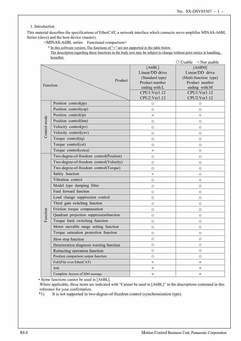
1. Introduction This material describes the specifications of EtherCAT, a network interface which connects servo amplifier MINAS-A6BL Series (slave) and the host device (master).
<MINAS-A6BL series Functional comparison> * In this software version, The functions of “×” are not supported in the table below.
The description regarding these functions in the body text may be subject to change without prior notice at handling, hereafter.
:Usable ×:Not usable
Product Function
[A6BL] Linear/DD drive (Standard type) Product number ending with:L
[A6BM] Linear/DD drive
(Multi-function type) Product number ending with:M
CPU1:Ver1.12 CPU2:Ver1.12
CPU1:Ver1.12 CPU2:Ver1.12
Con
trol m
ode
Position control(pp) ○ ○ Position control(csp) ○ ○ Position control(ip) × × Position control(hm) ○ ○ Velocity control(pv) ○ ○ Velocity control(csv) ○ ○ Torque control(tq) ○ ○ Torque control(cst) ○ ○ Torque control(cstca) × ×
Func
tion
Two-degree-of-freedom control(Position) ○ ○ Two-degree-of-freedom control(Velocity) ○ ○ Two-degree-of-freedom control(Torque) ○ ○ Safety function × ○ Vibration control ○ ○ Model type damping filter ○ ○ Feed forward function ○ ○ Load change suppression control ○ ○ Third gain switching function ○ ○ Friction torque compensation ○ ○ Quadrant projection suppressionfunction ○ ○ Torque limit switching function ○ ○ Motor movable range setting function ○ ○ Torque saturation protection function ○ ○ Slow stop function ○ ○ Deterioration diagnosis warning function ○ ○ Retracting operation function ○ ○ Position comparison output function ○ ○ FoE(File over EtherCAT) × × Jerk × × Complete Access of SDO message × ×
• Some functions cannot be used in [A6BL]. Where applicable, these items are indicated with “Cannot be used in [A6BL]” in the descriptions contained in this reference for your confirmation.
*1) It is not supported in two-degree-of-freedom control (synchronization type).
No. SX-DSV03307 - 2 -
R8.0 Motion Control Business Unit, Panasonic Corporation
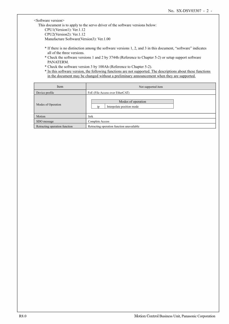
<Software version>
This document is to apply to the servo driver of the software versions below: CPU1(Version1): Ver.1.12 CPU2(Version2): Ver.1.12 Manufacture Software(Version3): Ver.1.00 * If there is no distinction among the software versions 1, 2, and 3 in this document, “software” indicates
all of the three versions. * Check the software versions 1 and 2 by 3744h (Reference to Chapter 5-2) or setup support software
PANATERM. * Check the software version 3 by 100Ah (Reference to Chapter 5-2). * In this software version, the following functions are not supported. The descriptions about these functions
in the document may be changed without a preliminary announcement when they are supported.
Item Not supported item
Device profile FoE (File Access over EtherCAT)
Modes of Operation
Modes of operation
ip Interpolate position mode
Motion Jerk SDO message Complete Access Retracting operation function Retracting operation function unavailable
No. SX-DSV03307 - 3 -
R8.0 Motion Control Business Unit, Panasonic Corporation
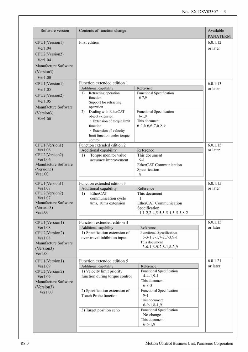
Software version Contents of function change Available PANATERM
CPU1(Version1) Ver1.04 CPU2(Version2)
Ver1.04 Manufacture Software (Version3)
Ver1.00
First edition 6.0.1.12 or later
CPU1(Version1) Ver1.05 CPU2(Version2)
Ver1.05 Manufacture Software (Version3)
Ver1.00
Function extended edition 1 Additional capability Reference 1) Retracting operation
function Support for retracting operation
Functional Specification 6-7,9
2) Dealing with EtherCAT object extension ・Extension of torque limit function ・Extension of velocity limit function under torque control
Functional Specification 6-1,9 This document 6-4,6-6,6-7,6-8,9
6.0.1.13 or later
CPU1(Version1) Ver1.06 CPU2(Version2)
Ver1.06 Manufacture Software (Version3) Ver1.00
Function extended edition 2 Additional capability Reference 1) Torque monitor value
accuracy improvement This document 9-1 EtherCAT Communication Specification
9
6.0.1.15 or later
CPU1(Version1) Ver1.07 CPU2(Version2)
Ver1.07 Manufacture Software (Version3) Ver1.00
Function extended edition 3 Additional capability Reference 1) EtherCAT
communication cycle 8ms, 10ms extension
This document 1 EtherCAT Communication Specification
1,1-2,2-4,5-5,5-5-1,5-5-3,8-2
6.0.1.15 or later
CPU1(Version1) Ver1.08 CPU2(Version2) Ver1.08 Manufacture Software (Version3) Ver1.00
Function extended edition 4 Additional capability Reference 1) Specification extension of over-travel inhibition input
Functional Specification 6-3-1,7-1,7-2,7-3,9-1 This document 3-6-1,6-9-2,8-1,8-3,9
6.0.1.15 or later
CPU1(Version1) Ver1.09 CPU2(Version2) Ver1.09 Manufacture Software (Version3)
Ver1.00
Function extended edition 5 Additional capability Reference 1) Velocity limit priority function during torque control
Functional Specification 4-4-1,9-1 This document 6-8-3
2) Specification extension of Touch Probe function
Functional Specification 9-1 This document 6-9-1,8-1,9
3) Target position echo Functional Specification No change This document 6-6-1,9
6.0.1.21 or later
No. SX-DSV03307 - 4 -
R8.0 Motion Control Business Unit, Panasonic Corporation
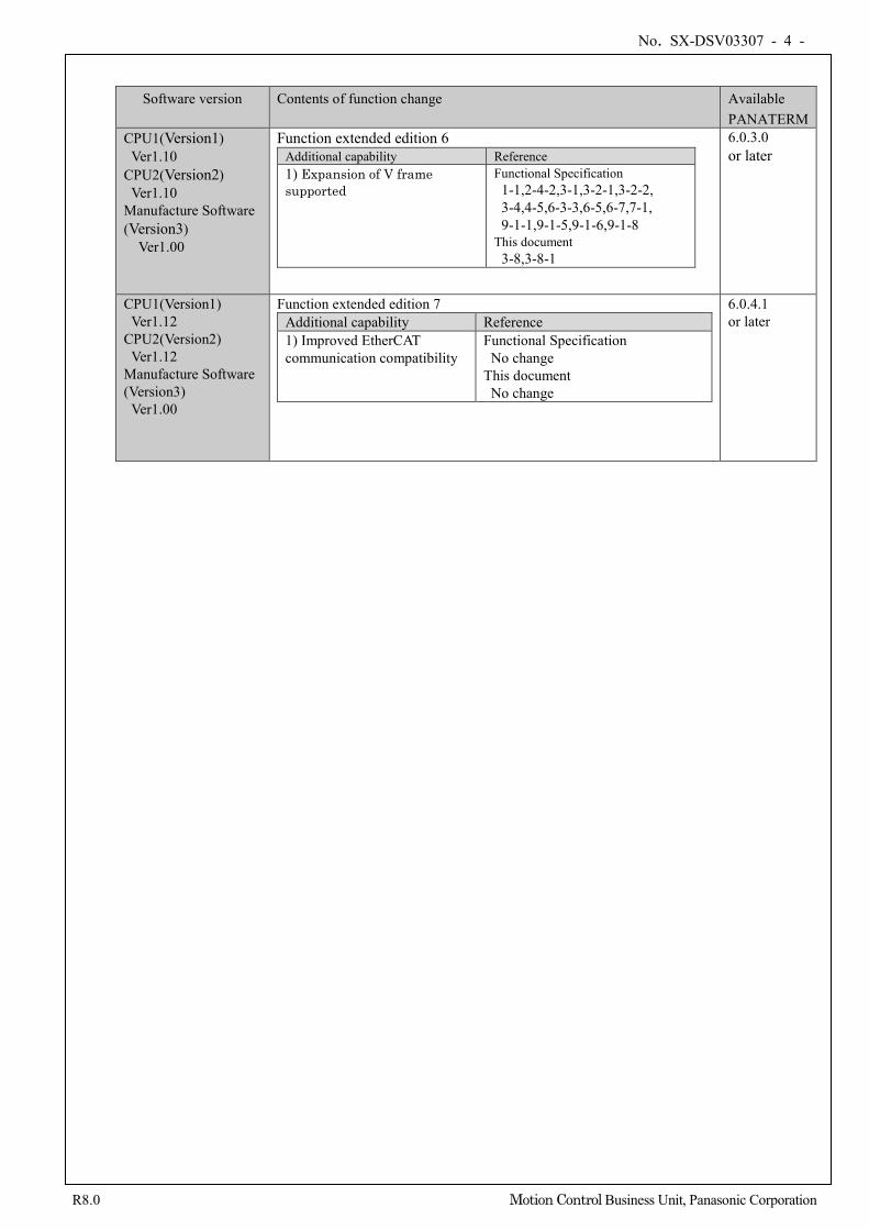
Software version Contents of function change Available PANATERM
CPU1(Version1) Ver1.10 CPU2(Version2) Ver1.10 Manufacture Software (Version3)
Ver1.00
Function extended edition 6 Additional capability Reference 1) Expansion of V frame supported
Functional Specification 1-1,2-4-2,3-1,3-2-1,3-2-2, 3-4,4-5,6-3-3,6-5,6-7,7-1, 9-1-1,9-1-5,9-1-6,9-1-8
This document 3-8,3-8-1
6.0.3.0 or later
CPU1(Version1) Ver1.12
CPU2(Version2) Ver1.12
Manufacture Software (Version3)
Ver1.00
Function extended edition 7 Additional capability Reference 1) Improved EtherCAT communication compatibility
Functional Specification No change
This document No change
6.0.4.1 or later
No. SX-DSV03307 - 5 -
R8.0 Motion Control Business Unit, Panasonic Corporation
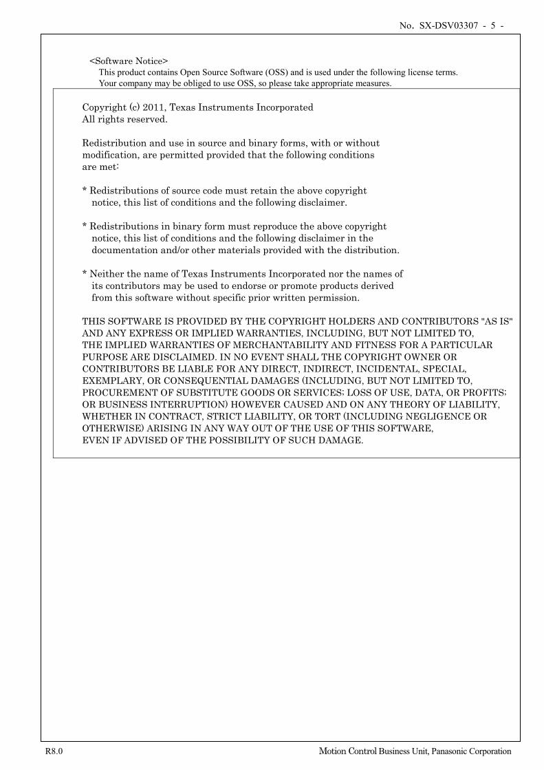
<Software Notice> This product contains Open Source Software (OSS) and is used under the following license terms. Your company may be obliged to use OSS, so please take appropriate measures.
Copyright (c) 2011, Texas Instruments Incorporated All rights reserved. Redistribution and use in source and binary forms, with or without modification, are permitted provided that the following conditions are met: * Redistributions of source code must retain the above copyright notice, this list of conditions and the following disclaimer. * Redistributions in binary form must reproduce the above copyright notice, this list of conditions and the following disclaimer in the documentation and/or other materials provided with the distribution. * Neither the name of Texas Instruments Incorporated nor the names of its contributors may be used to endorse or promote products derived from this software without specific prior written permission. THIS SOFTWARE IS PROVIDED BY THE COPYRIGHT HOLDERS AND CONTRIBUTORS "AS IS" AND ANY EXPRESS OR IMPLIED WARRANTIES, INCLUDING, BUT NOT LIMITED TO, THE IMPLIED WARRANTIES OF MERCHANTABILITY AND FITNESS FOR A PARTICULAR PURPOSE ARE DISCLAIMED. IN NO EVENT SHALL THE COPYRIGHT OWNER OR CONTRIBUTORS BE LIABLE FOR ANY DIRECT, INDIRECT, INCIDENTAL, SPECIAL, EXEMPLARY, OR CONSEQUENTIAL DAMAGES (INCLUDING, BUT NOT LIMITED TO, PROCUREMENT OF SUBSTITUTE GOODS OR SERVICES; LOSS OF USE, DATA, OR PROFITS; OR BUSINESS INTERRUPTION) HOWEVER CAUSED AND ON ANY THEORY OF LIABILITY, WHETHER IN CONTRACT, STRICT LIABILITY, OR TORT (INCLUDING NEGLIGENCE OR OTHERWISE) ARISING IN ANY WAY OUT OF THE USE OF THIS SOFTWARE, EVEN IF ADVISED OF THE POSSIBILITY OF SUCH DAMAGE.
No. SX-DSV03307 - 6 -
R8.0 Motion Control Business Unit, Panasonic Corporation
<Target user>
This document is intended for those who design host controller for the servo driver MINAS-A6BL series. <Related document>
SX-DSV03190: Standard specifications (A6BL Series, other than V frame) SX-DSV03510: Standard specifications (A6BL series V frame)
(The specification about hardware, Safety Precautions,Warranty etc. is indicated. Please be sure to read carefully, after understanding the contents, refer to this specification.)
SX-DSV03306: Technical document (Basic function specifications) < Caution >
(1) No part or whole of the contents in this document may be reused or reproduced without our written permission.
(2) The contents (specification, software version, etc.) of this document is subject to change without prior notice due to the improvement of the product.
(3) For the MINAS-A6BL series, the shipment setting value was changed from the previous series (MINAS-A5BL series, etc.) by enabling “2 degrees of freedom control mode”, etc. Note that the parameters need to be adjusted again if replacing with MINAS-A6BL series from the previous series. See the Standard specifications for the shipment setting value of the MINAS-A6BL series.
(4) MINAS-A6BL series may not be fully compatible operation with the previous series(MINAS-A5BL series). In the case of replacing the previous series to MINAS-A6BL series, be sure to evaluate.
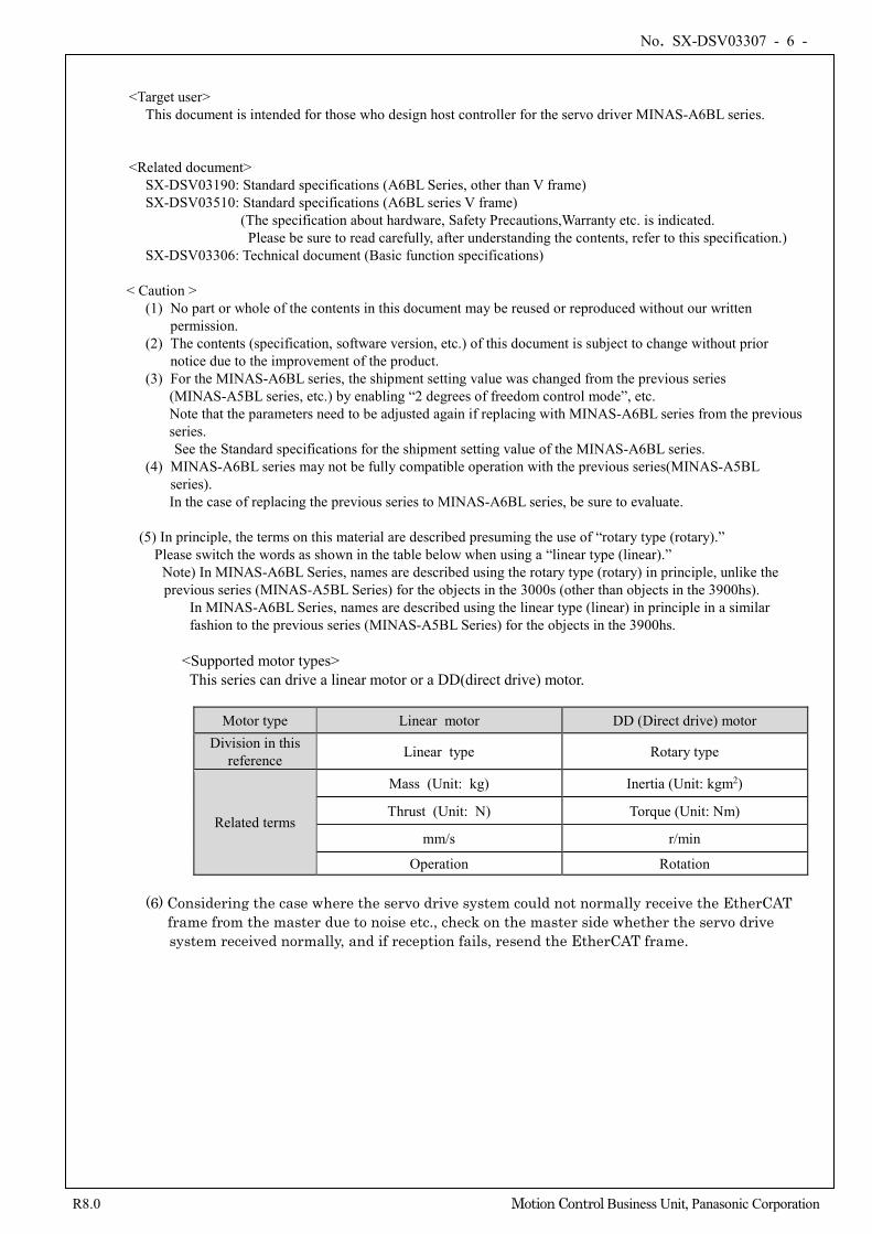
(5) In principle, the terms on this material are described presuming the use of “rotary type (rotary).” Please switch the words as shown in the table below when using a “linear type (linear).”
Note) In MINAS-A6BL Series, names are described using the rotary type (rotary) in principle, unlike the previous series (MINAS-A5BL Series) for the objects in the 3000s (other than objects in the 3900hs).
In MINAS-A6BL Series, names are described using the linear type (linear) in principle in a similar fashion to the previous series (MINAS-A5BL Series) for the objects in the 3900hs.
<Supported motor types> This series can drive a linear motor or a DD(direct drive) motor.
Motor type Linear motor DD (Direct drive) motor Division in this
reference Linear type Rotary type
Related terms
Mass (Unit: kg) Inertia (Unit: kgm2)
Thrust (Unit: N) Torque (Unit: Nm)
mm/s r/min
Operation Rotation
(6) Considering the case where the servo drive system could not normally receive the EtherCAT frame from the master due to noise etc., check on the master side whether the servo drive
system received normally, and if reception fails, resend the EtherCAT frame.
No. SX-DSV03307 - 7 -
R8.0 Motion Control Business Unit, Panasonic Corporation
1-1 Start-up guide
A schematic procedure until it can operate with a motor simple substance by pp control is described.
Note: This section is only for reference and does not guarantee the operation. Some descriptions including those for the homing operation are omitted. For details, refer to this document and the specifications issued by ETG. In addition, it is necessary to change the shipment settings according to the equipment environment. For each parameter and the shipment values of the EtherCAT objects, refer to the Standard specification.
1) Preparation and connection (Mainly refer to Chapter 2 and Chapter 3)
- Connect a master with a slave , and a motor with a slave. - In EtherCAT communication, the ESI file (xml file) which indicated EtherCAT slave information is needed.
Please save the ESI file offered from our company at the preservation place of the ESI file specified by the master. * 1)
- A master generates ENI based on ESI offered from our company (using a configuration tool), and builds an EtherCAT network using ENI.(Refer to the operation manual of a master for details.) - Station alias is set up.
As for the value of Configured Station Alias(0004h) of SII, 0 is set up at the time of shipment. When it set up Station Alias by front RSW, once switch on a control power supply, write 3741h=0 in EEPROM, and set up Station Alias by RSW after turning off a control power supply. (The range of Station Alias which can be set up only by RSW is 0-255. When it set up 256 or more, refer to section 3-8-2.)
Alternatively, setting through AL Status Code (Explicit Device ID) is available. For details, refer to section 3-8-2. The master reads the set values of the Configured Station Alias (0012h) of the ESC register and sets them to the Configured Station Address (0010h). Thereby addresses such as FPRD commands used in the mailbox are set.
- Switch on a power supply. Switch on both the main power and the control power. Check 7 segment LED in the front after power activation, and check that the error has not occurred.
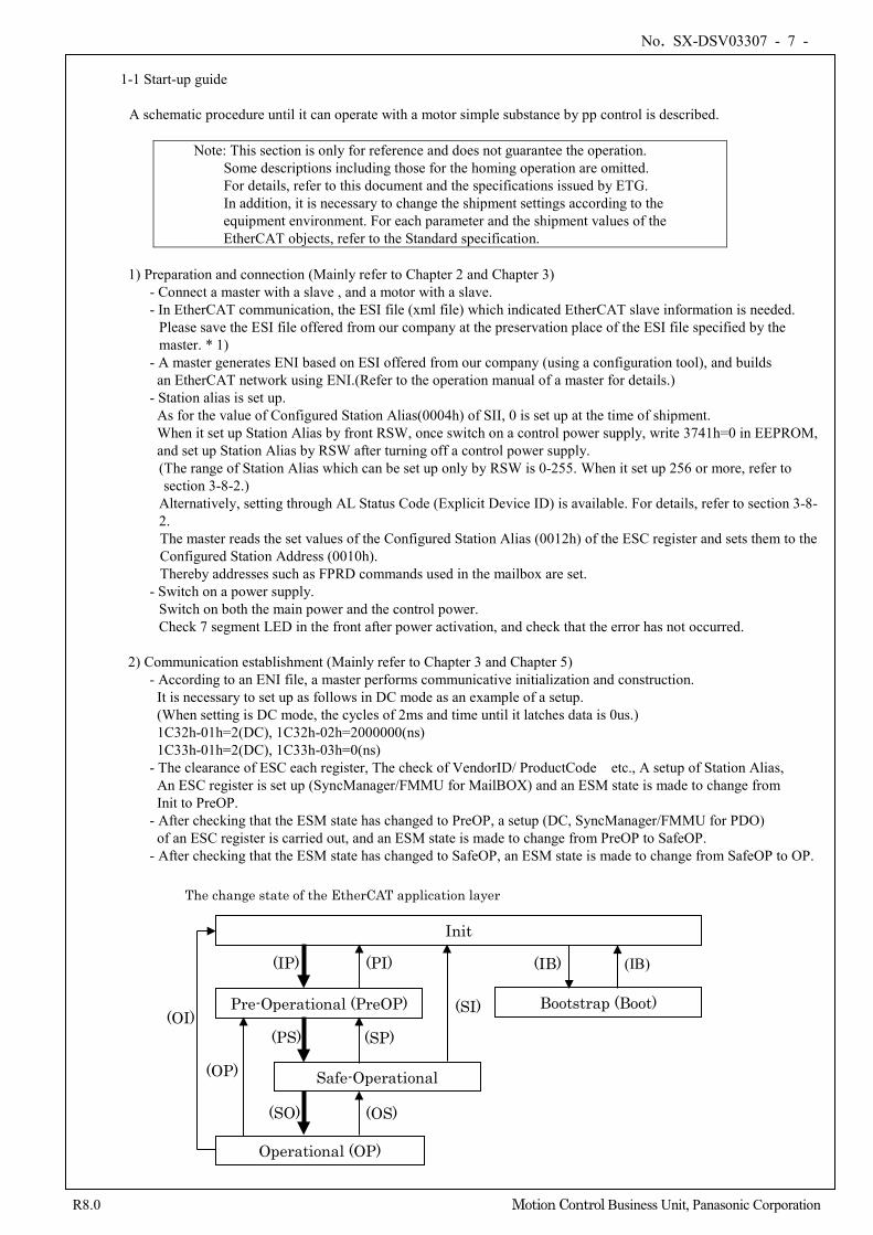
2) Communication establishment (Mainly refer to Chapter 3 and Chapter 5)
- According to an ENI file, a master performs communicative initialization and construction. It is necessary to set up as follows in DC mode as an example of a setup. (When setting is DC mode, the cycles of 2ms and time until it latches data is 0us.)
1C32h-01h=2(DC), 1C32h-02h=2000000(ns) 1C33h-01h=2(DC), 1C33h-03h=0(ns)
- The clearance of ESC each register, The check of VendorID/ ProductCode etc., A setup of Station Alias, An ESC register is set up (SyncManager/FMMU for MailBOX) and an ESM state is made to change from
Init to PreOP. - After checking that the ESM state has changed to PreOP, a setup (DC, SyncManager/FMMU for PDO)
of an ESC register is carried out, and an ESM state is made to change from PreOP to SafeOP. - After checking that the ESM state has changed to SafeOP, an ESM state is made to change from SafeOP to OP.
Safe-Operational
Pre-Operational (PreOP)
Init
(OI)
(OP)
(IP) (PI)
(OS)
(PS)
(SO)
(SP)
Operational (OP)
(SI)
The change state of the EtherCAT application layer
Bootstrap (Boot)
(IB) (IB)
No. SX-DSV03307 - 8 -
R8.0 Motion Control Business Unit, Panasonic Corporation
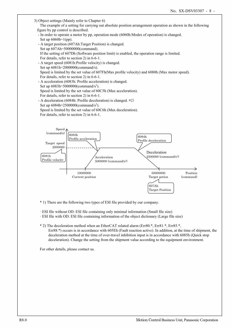
3) Object settings (Mainly refer to Chapter 6) The example of a setting for carrying out absolute position arrangement operation as shown in the following
figure by pp control is described. - In order to operate a motor by pp, operation mode (6060h:Modes of operation) is changed.
Set up 6060h=1(pp). - A target position (607Ah:Target Position) is changed. Set up 607Ah=50000000(command). If the setting of 607Dh (Software position limit) is enabled, the operation range is limited. For details, refer to section 2) in 6-6-1.
- A target speed (6081h:Profile velocity) is changed. Set up 6081h=2000000(command/s). Speed is limited by the set value of 607Fh(Max profile velocity) and 6080h (Max motor speed). For details, refer to section 2) in 6-6-1.
- A acceleration (6083h: Profile acceleration) is changed. Set up 6083h=5000000(command/s2). Speed is limited by the set value of 60C5h (Max acceleration). For details, refer to section 2) in 6-6-1.
- A deceleration (6084h: Profile deceleration) is changed. *2) Set up 6084h=2500000(command/s2). Speed is limited by the set value of 60C6h (Max deceleration). For details, refer to section 2) in 6-6-1.
* 1) There are the following two types of ESI file provided by our company. · ESI file without OD: ESI file containing only minimal information (Small file size) · ESI file with OD: ESI file containing information of the object dictionary (Large file size) * 2) The deceleration method when an EtherCAT related alarm (Err80.*, Err81.*, Err85.*,
Err88.*) occurs is in accordance with 605Eh (Fault reaction active). In addition, at the time of shipment, the deceleration method at the time of over-travel inhibition input is in accordance with 6085h (Quick stop deceleration). Change the setting from the shipment value according to the equipment environment.
For other details, please contact us.
Position (command)
Speed (command/s)
10000000 Current position
50000000 Target potion
Target speed 2000000
Acceleration 5000000 (command/s2)
Deceleration 2500000 (command/s2)
607Ah Target Position
6081h Profile velocity
6083h Profile acceleration 6084h
Profile deceleration
No. SX-DSV03307 - 9 -
R8.0 Motion Control Business Unit, Panasonic Corporation
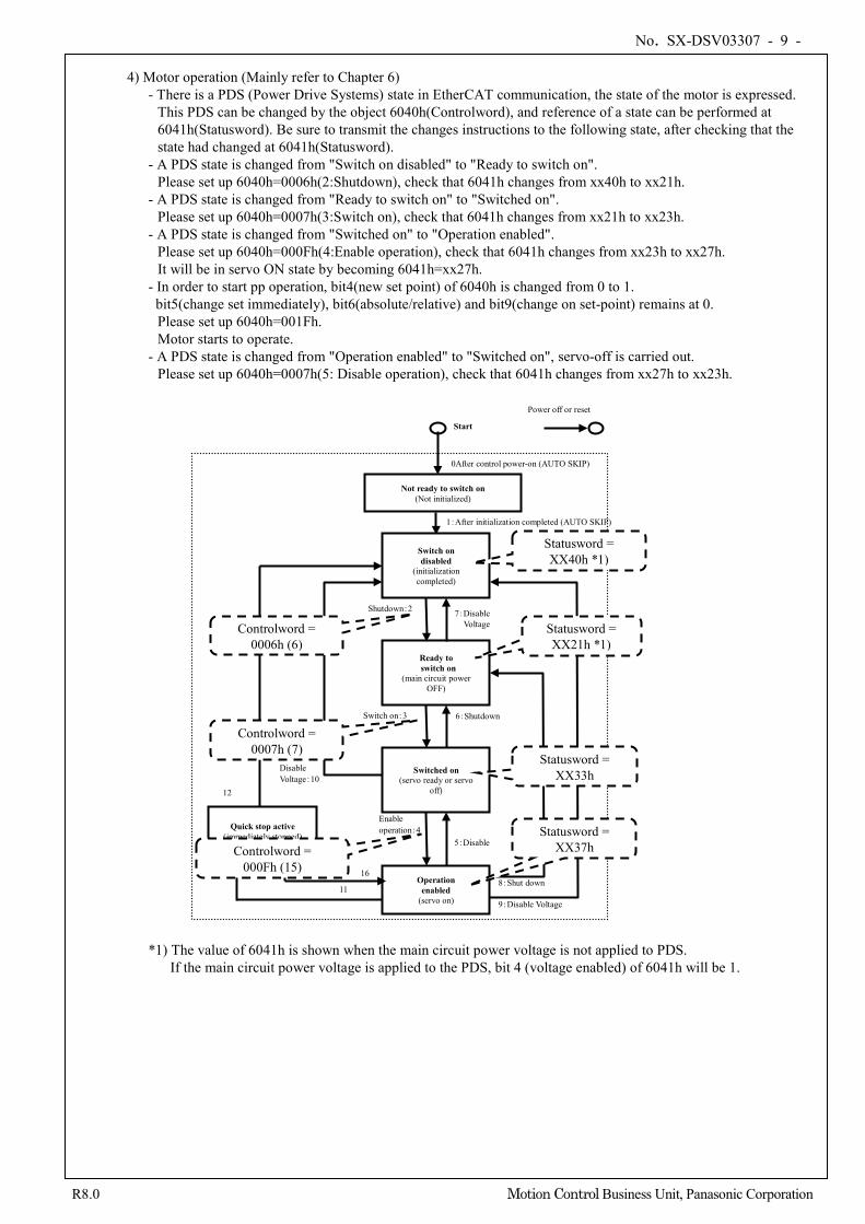
4) Motor operation (Mainly refer to Chapter 6)
- There is a PDS (Power Drive Systems) state in EtherCAT communication, the state of the motor is expressed. This PDS can be changed by the object 6040h(Controlword), and reference of a state can be performed at 6041h(Statusword). Be sure to transmit the changes instructions to the following state, after checking that the state had changed at 6041h(Statusword).
- A PDS state is changed from "Switch on disabled" to "Ready to switch on". Please set up 6040h=0006h(2:Shutdown), check that 6041h changes from xx40h to xx21h.
- A PDS state is changed from "Ready to switch on" to "Switched on". Please set up 6040h=0007h(3:Switch on), check that 6041h changes from xx21h to xx23h.
- A PDS state is changed from "Switched on" to "Operation enabled". Please set up 6040h=000Fh(4:Enable operation), check that 6041h changes from xx23h to xx27h. It will be in servo ON state by becoming 6041h=xx27h.
- In order to start pp operation, bit4(new set point) of 6040h is changed from 0 to 1. bit5(change set immediately), bit6(absolute/relative) and bit9(change on set-point) remains at 0.
Please set up 6040h=001Fh. Motor starts to operate.
- A PDS state is changed from "Operation enabled" to "Switched on", servo-off is carried out. Please set up 6040h=0007h(5: Disable operation), check that 6041h changes from xx27h to xx23h.
*1) The value of 6041h is shown when the main circuit power voltage is not applied to PDS.
If the main circuit power voltage is applied to the PDS, bit 4 (voltage enabled) of 6041h will be 1.
Power off or reset
Not ready to switch on (Not initialized)
0After control power-on (AUTO SKIP)
1:After initialization completed (AUTO SKIP)
Operation enabled
(servo on)
Switched on (servo ready or servo
off)
Enable operation:4
5:Disable
Ready to switch on
(main circuit power OFF)
8:Shut down
Switch on:3 6:Shutdown
Start
Switch on disabled
(initialization completed)
Shutdown:2 7:Disable Voltage
9:Disable Voltage
Disable Voltage:10
Quick stop active (immediately stopped)
16
11
12
Statusword = XX40h *1)
Statusword = XX21h *1)
Statusword = XX33h
Statusword = XX37h
Controlword = 0006h (6)
Controlword = 0007h (7)
Controlword = 000Fh (15)
16
No. SX-DSV03307 - 10 -
R8.0 Motion Control Business Unit, Panasonic Corporation
5) When the motor does not operate
- When servo-on is not performed, before the PDS state inside driver changes, there is a possibility of having transmitted the changes commands to the following state. Transmit the changes commands to the following state after checking that the PDS change state has been completed.
- Although servo-on is carried out, when the motor does not operate, there may be inaccurate setting object. Check the settings of the object. In particular, make sure that the motor operation is not limited by objects that set a maximum value, such as 6080h (Max motor speed), or objects that set an operation range, such as 607Dh (Software position limit). If bit 11 (internal limit active) of 6041h (Statusword) is 1, internal limitation is imposed. Refer to “6-4. Statusword (6041h)” to eliminate the cause of the internal limitation.
- When alarm is occurred, remove the factor of alarm after referring to Chapter 8 “EtherCAT Relevant Protection Functions” of this document or Chapter 7 “Protective function/Alarm function” in technical reference functional specification (SX-DSV03306). After factor of alarm is removed, perform alarm clear after referring to Chapter 8-4 “Clear error (alarm)/Clear
warning” of this document.
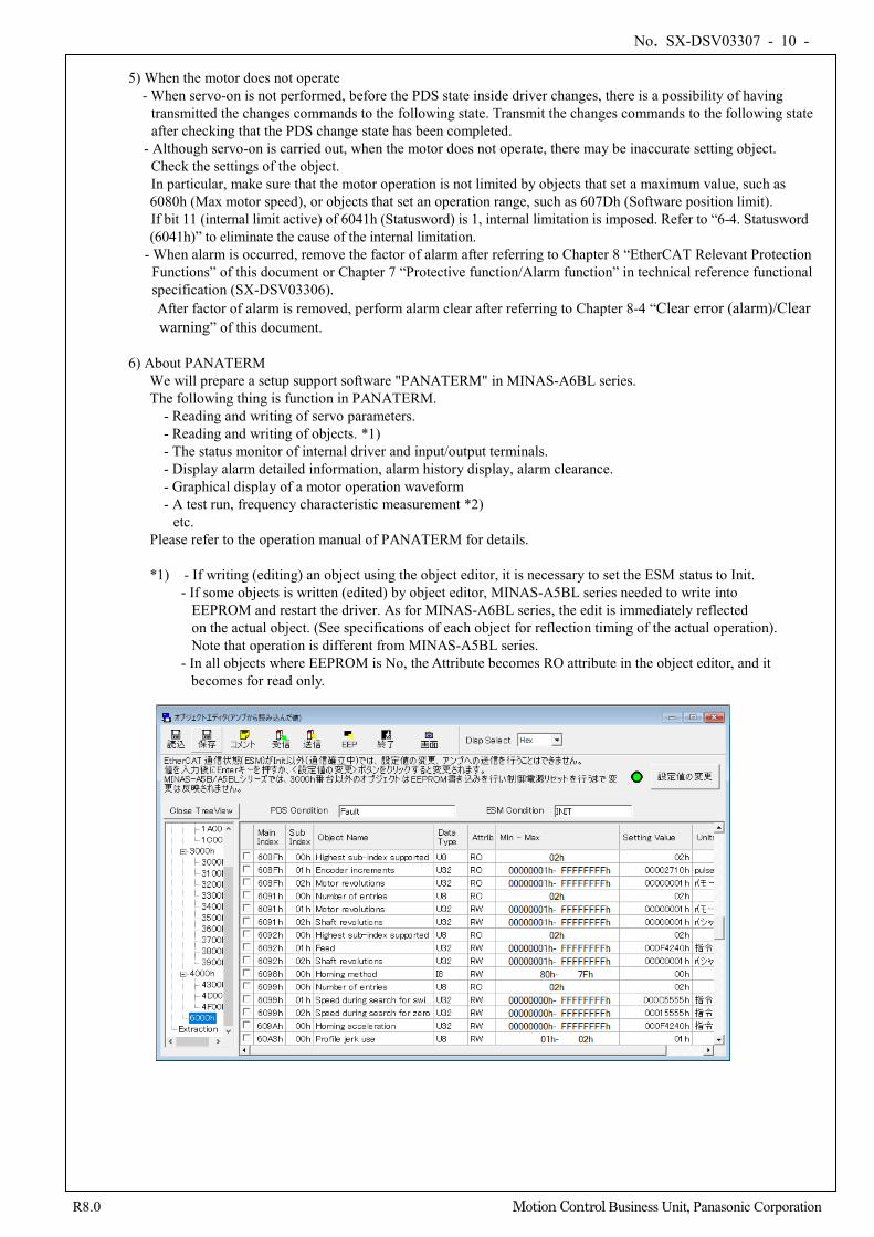
6) About PANATERM We will prepare a setup support software "PANATERM" in MINAS-A6BL series. The following thing is function in PANATERM.
- Reading and writing of servo parameters. - Reading and writing of objects. *1) - The status monitor of internal driver and input/output terminals. - Display alarm detailed information, alarm history display, alarm clearance. - Graphical display of a motor operation waveform - A test run, frequency characteristic measurement *2)
etc. Please refer to the operation manual of PANATERM for details. *1) - If writing (editing) an object using the object editor, it is necessary to set the ESM status to Init.
- If some objects is written (edited) by object editor, MINAS-A5BL series needed to write into EEPROM and restart the driver. As for MINAS-A6BL series, the edit is immediately reflected on the actual object. (See specifications of each object for reflection timing of the actual operation). Note that operation is different from MINAS-A5BL series.
- In all objects where EEPROM is No, the Attribute becomes RO attribute in the object editor, and it becomes for read only.
No. SX-DSV03307 - 11 -
R8.0 Motion Control Business Unit, Panasonic Corporation
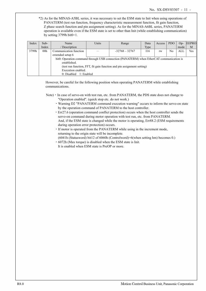
*2) As for the MINAS-A5BL series, it was necessary to set the ESM state to Init when using operations of PANATERM (test run function, frequency characteristic measurement function, fit gain function, Z phase search function and pin assignment setting). As for the MINAS-A6BL series, PANATERM operation is available even if the ESM state is set to other than Init (while establishing communication) by setting 3799h bit0=1.
Index Sub- Index
Name / Description
Units Range Data Type
Access PDO Op- mode
EEPROM
3799h 00h Communication function extended setup 6
- -32768 – 32767 I16 rw No ALL Yes
bit0: Operation command through USB connection (PANATERM) when EtherCAT communication is established. (test run function, FFT, fit gain function and pin assignment setting) Execution enabled. 0: Disabled 1: Enabled
However, be careful for the following position when operating PANATERM while establishing communications. Note)・In case of servo-on with test run, etc. from PANATERM, the PDS state does not change to
"Operation enabled". (quick stop etc. do not work.) ・Warning D2 "PANATERM command execution warning" occurs to inform the servo-on state
by the operation command of PANATERM to the host controller. ・Err27.6 (operation command conflict protection) occurs when the host controller sends the
servo-on command during motor operation with test run, etc. from PANATERM. And, if the ESM state is changed while the motor is operating, Err88.2 (ESM requirements during operation error protection) occurs.
・If motor is operated from the PANATERM while using in the increment mode, returning to the origin state will be incomplete.
(6041h (Statusword) bit12 of 6060h (Controlword)=6(when setting hm) becomes 0.) ・6072h (Max torque) is disabled when the ESM state is Init.
It is enabled when ESM state is PreOP or more.
No. SX-DSV03307 - 12 -
R8.0 Motion Control Business Unit, Panasonic Corporation
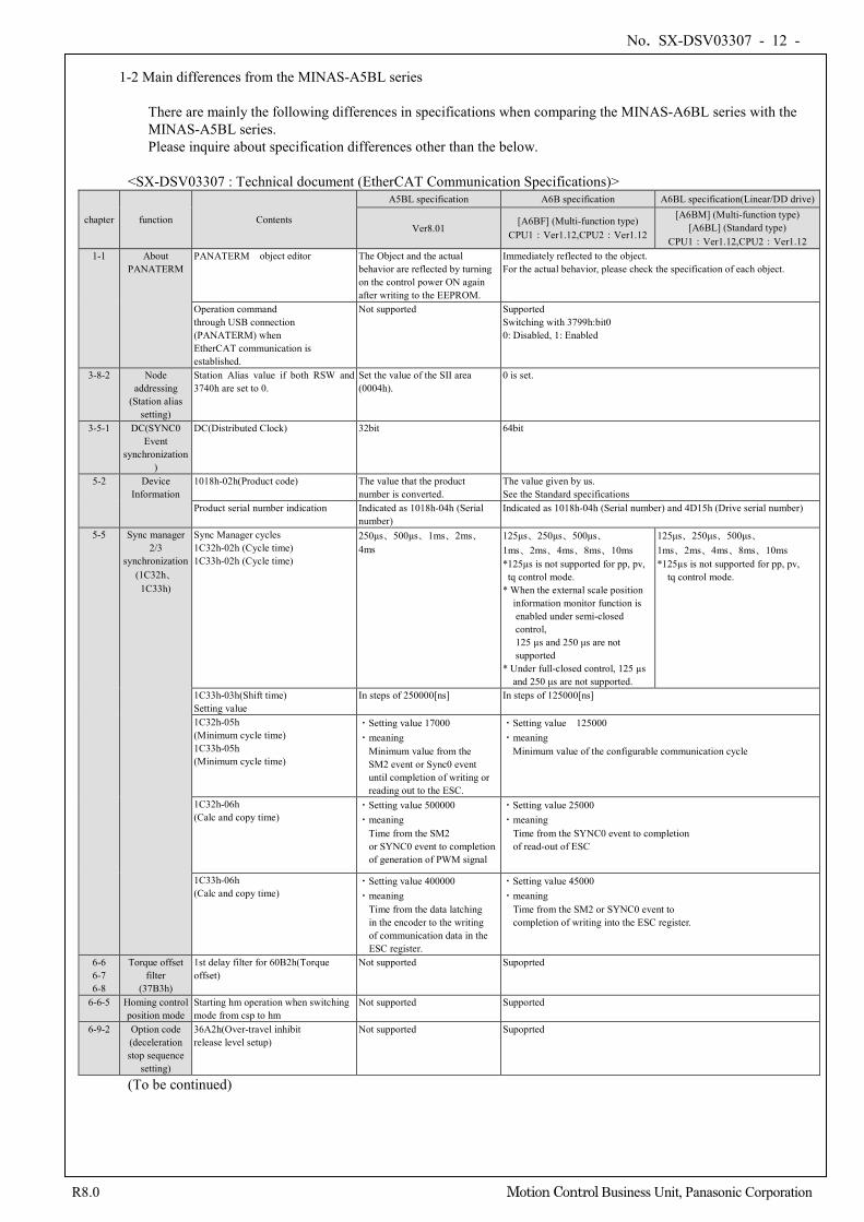
1-2 Main differences from the MINAS-A5BL series
There are mainly the following differences in specifications when comparing the MINAS-A6BL series with the MINAS-A5BL series. Please inquire about specification differences other than the below.
<SX-DSV03307 : Technical document (EtherCAT Communication Specifications)>
chapter function Contents
A5BL specification A6B specification A6BL specification(Linear/DD drive)
Ver8.01 [A6BF] (Multi-function type)
CPU1:Ver1.12,CPU2:Ver1.12
[A6BM] (Multi-function type) [A6BL] (Standard type)
CPU1:Ver1.12,CPU2:Ver1.12 1-1 About
PANATERM PANATERM object editor
The Object and the actual behavior are reflected by turning on the control power ON again after writing to the EEPROM.
Immediately reflected to the object. For the actual behavior, please check the specification of each object.
Operation command through USB connection (PANATERM) when EtherCAT communication is established.
Not supported Supported Switching with 3799h:bit0 0: Disabled, 1: Enabled
3-8-2 Node addressing
(Station alias setting)
Station Alias value if both RSW and 3740h are set to 0.
Set the value of the SII area (0004h).
0 is set.
3-5-1 DC(SYNC0 Event
synchronization)
DC(Distributed Clock) 32bit 64bit
5-2 Device Information
1018h-02h(Product code) The value that the product number is converted.
The value given by us. See the Standard specifications
Product serial number indication Indicated as 1018h-04h (Serial number)
Indicated as 1018h-04h (Serial number) and 4D15h (Drive serial number)
5-5 Sync manager 2/3
synchronization (1C32h、
1C33h)
Sync Manager cycles 1C32h-02h (Cycle time) 1C33h-02h (Cycle time)
250μs、500μs、1ms、2ms、4ms
125μs、250μs、500μs、 1ms、2ms、4ms、8ms、10ms *125µs is not supported for pp, pv, tq control mode.
* When the external scale position information monitor function is enabled under semi-closed
control, 125 µs and 250 μs are not
supported * Under full-closed control, 125 µs
and 250 μs are not supported.
125μs、250μs、500μs、 1ms、2ms、4ms、8ms、10ms *125µs is not supported for pp, pv,
tq control mode.
1C33h-03h(Shift time) Setting value
In steps of 250000[ns] In steps of 125000[ns]
1C32h-05h (Minimum cycle time) 1C33h-05h (Minimum cycle time)
・Setting value 17000 ・meaning
Minimum value from the SM2 event or Sync0 event until completion of writing or reading out to the ESC.
・Setting value 125000 ・meaning
Minimum value of the configurable communication cycle
1C32h-06h (Calc and copy time)
・Setting value 500000 ・meaning
Time from the SM2 or SYNC0 event to completion of generation of PWM signal
・Setting value 25000 ・meaning Time from the SYNC0 event to completion of read-out of ESC
1C33h-06h (Calc and copy time)
・Setting value 400000 ・meaning Time from the data latching
in the encoder to the writing of communication data in the ESC register.
・Setting value 45000 ・meaning Time from the SM2 or SYNC0 event to completion of writing into the ESC register.
6-6 6-7 6-8
Torque offset filter
(37B3h)
1st delay filter for 60B2h(Torque offset)
Not supported Supoprted
6-6-5 Homing control position mode
Starting hm operation when switching mode from csp to hm
Not supported Supported
6-9-2 Option code (deceleration stop sequence
setting)
36A2h(Over-travel inhibit release level setup)
Not supported Supoprted
(To be continued)
No. SX-DSV03307 - 13 -
R8.0 Motion Control Business Unit, Panasonic Corporation
<SX-DSV03307 : Technical document (EtherCAT Communication Specifications)>
chapter function Contents
A5BL specification A6B specification A6BL specification(Linear/DD drive)
Ver8.01 [A6BF] (Multi-function type)
CPU1:Ver1.12,CPU2:Ver1.12
[A6BM] (Multi-function type) [A6BL] (Standard type)
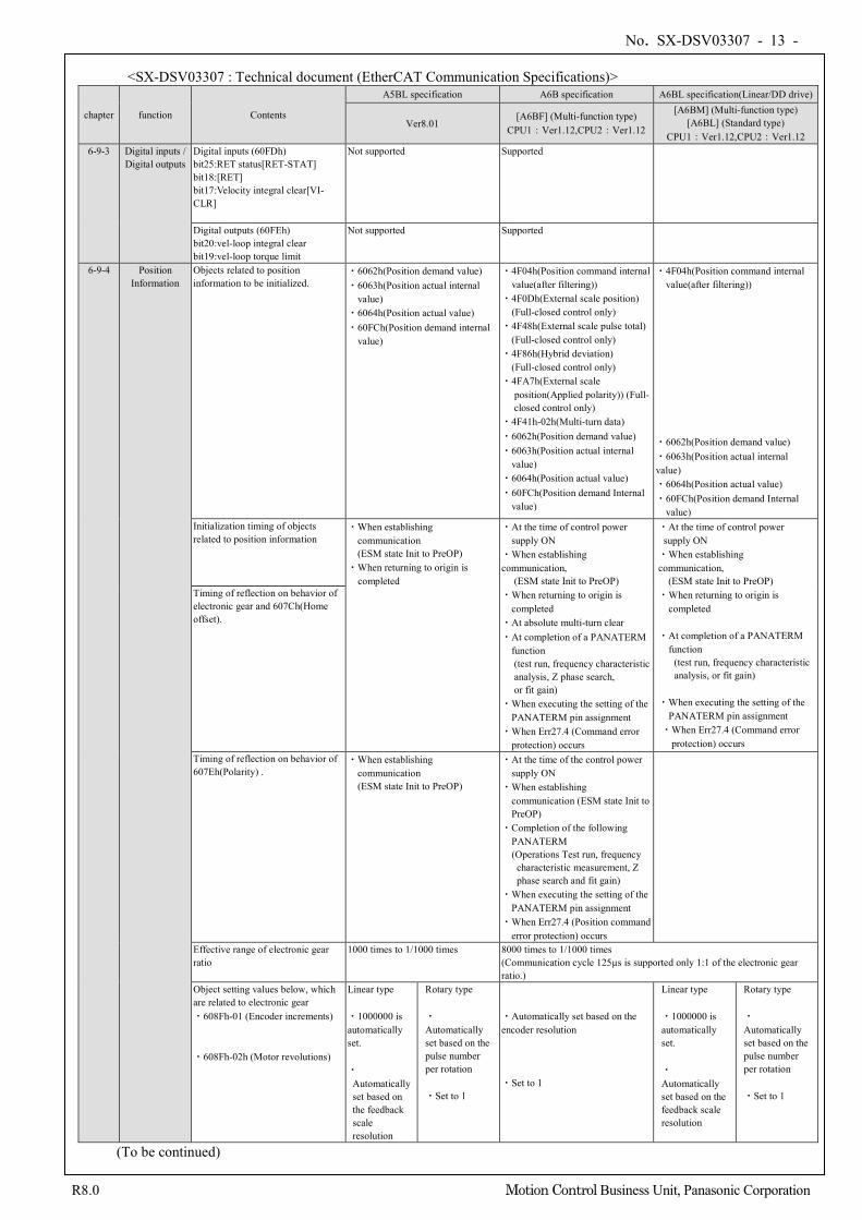
CPU1:Ver1.12,CPU2:Ver1.12 6-9-3 Digital inputs /
Digital outputs Digital inputs (60FDh) bit25:RET status[RET-STAT] bit18:[RET] bit17:Velocity integral clear[VI-CLR]
Not supported Supported
Digital outputs (60FEh) bit20:vel-loop integral clear bit19:vel-loop torque limit
Not supported Supported
6-9-4 Position Information
Objects related to position information to be initialized.
・6062h(Position demand value) ・6063h(Position actual internal
value) ・6064h(Position actual value) ・60FCh(Position demand internal
value)
・4F04h(Position command internal value(after filtering)) ・4F0Dh(External scale position) (Full-closed control only) ・4F48h(External scale pulse total)
(Full-closed control only) ・4F86h(Hybrid deviation)
(Full-closed control only) ・4FA7h(External scale
position(Applied polarity)) (Full-closed control only)
・4F41h-02h(Multi-turn data) ・6062h(Position demand value) ・6063h(Position actual internal
value) ・6064h(Position actual value) ・60FCh(Position demand Internal
value)
・4F04h(Position command internal value(after filtering))
・6062h(Position demand value) ・6063h(Position actual internal value) ・6064h(Position actual value) ・60FCh(Position demand Internal
value) Initialization timing of objects related to position information
・When establishing communication (ESM state Init to PreOP)
・When returning to origin is completed
・At the time of control power supply ON
・When establishing communication,
(ESM state Init to PreOP) ・When returning to origin is
completed ・At absolute multi-turn clear ・At completion of a PANATERM
function (test run, frequency characteristic analysis, Z phase search, or fit gain)
・When executing the setting of the PANATERM pin assignment
・When Err27.4 (Command error protection) occurs
・At the time of control power supply ON
・When establishing communication,
(ESM state Init to PreOP) ・When returning to origin is
completed ・At completion of a PANATERM
function (test run, frequency characteristic analysis, or fit gain)
・When executing the setting of the
PANATERM pin assignment ・When Err27.4 (Command error
protection) occurs
Timing of reflection on behavior of electronic gear and 607Ch(Home offset).
Timing of reflection on behavior of 607Eh(Polarity) .
・When establishing communication (ESM state Init to PreOP)
・At the time of the control power supply ON
・When establishing communication (ESM state Init to PreOP)
・Completion of the following PANATERM
(Operations Test run, frequency characteristic measurement, Z phase search and fit gain)
・When executing the setting of the PANATERM pin assignment
・When Err27.4 (Position command error protection) occurs
Effective range of electronic gear ratio
1000 times to 1/1000 times 8000 times to 1/1000 times (Communication cycle 125µs is supported only 1:1 of the electronic gear ratio.)
Object setting values below, which are related to electronic gear ・608Fh-01 (Encoder increments)
・608Fh-02h (Motor revolutions)
Linear type ・1000000 is automatically set. ・
Automatically set based on the feedback scale resolution
Rotary type ・
Automatically set based on the pulse number per rotation ・Set to 1
・Automatically set based on the encoder resolution ・Set to 1
Linear type ・1000000 is automatically set. ・
Automatically set based on the feedback scale resolution
Rotary type ・
Automatically set based on the pulse number per rotation ・Set to 1
(To be continued)
No. SX-DSV03307 - 14 -
R8.0 Motion Control Business Unit, Panasonic Corporation
<SX-DSV03307 : Technical document (EtherCAT Communication Specifications)>
chapter function Contents
A5BL specification A6B specification A6BL specification(Linear/DD drive)
Ver8.01 [A6BF] (Multi-function type)
CPU1:Ver1.12,CPU2:Ver1.12
[A6BM] (Multi-function type) [A6BL] (Standard type)
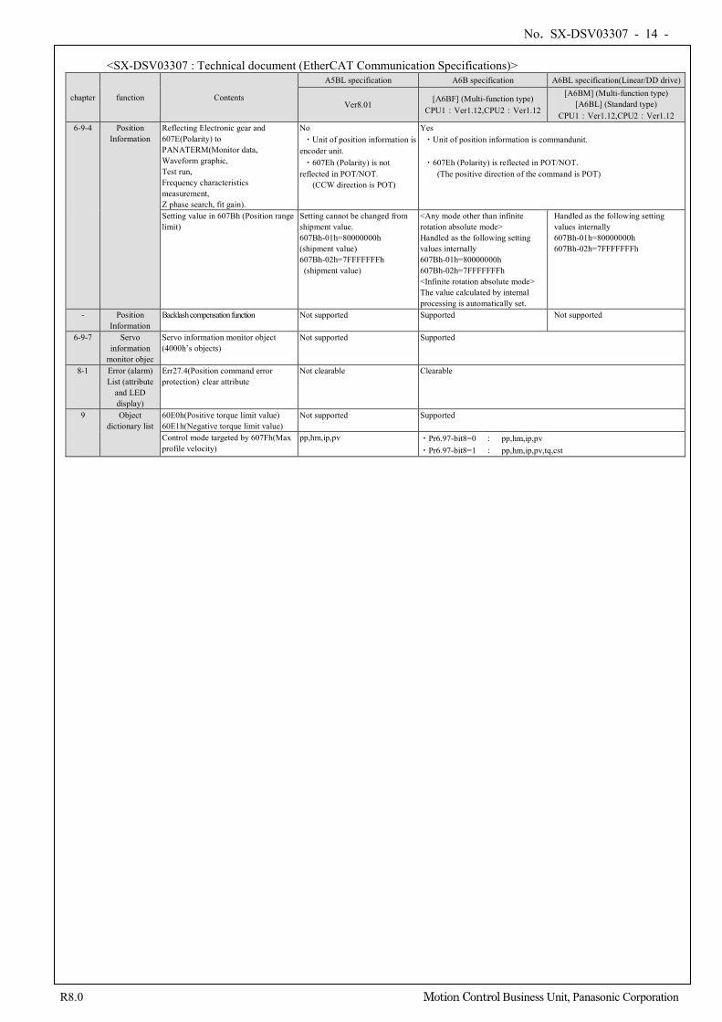
CPU1:Ver1.12,CPU2:Ver1.12 6-9-4 Position
Information Reflecting Electronic gear and 607E(Polarity) to PANATERM(Monitor data, Waveform graphic, Test run, Frequency characteristics measurement, Z phase search, fit gain).
No ・Unit of position information is
encoder unit. ・607Eh (Polarity) is not
reflected in POT/NOT. (CCW direction is POT)
Yes ・Unit of position information is commandunit. ・607Eh (Polarity) is reflected in POT/NOT.
(The positive direction of the command is POT)
Setting value in 607Bh (Position range limit)
Setting cannot be changed from shipment value. 607Bh-01h=80000000h (shipment value) 607Bh-02h=7FFFFFFFh (shipment value)
<Any mode other than infinite rotation absolute mode> Handled as the following setting values internally 607Bh-01h=80000000h 607Bh-02h=7FFFFFFFh <Infinite rotation absolute mode> The value calculated by internal processing is automatically set.
Handled as the following setting values internally 607Bh-01h=80000000h 607Bh-02h=7FFFFFFFh
- Position Information
Backlash compensation function Not supported Supported Not supported
6-9-7 Servo information
monitor objec
Servo information monitor object (4000h’s objects)
Not supported Supported
8-1 Error (alarm) List (attribute
and LED display)
Err27.4(Position command error protection) clear attribute
Not clearable Clearable
9 Object dictionary list
60E0h(Positive torque limit value) 60E1h(Negative torque limit value)
Not supported Supported
Control mode targeted by 607Fh(Max profile velocity)
pp,hm,ip,pv ・Pr6.97-bit8=0 : pp,hm,ip,pv ・Pr6.97-bit8=1 : pp,hm,ip,pv,tq,cst
No. SX-DSV03307 - 15 -
R8.0 Motion Control Business Unit, Panasonic Corporation
<SX-DSV03304: Technical document (Basic function specifications)> Please refer to technical document Basic function specification (SX-DSV03304), Section 1-7 for details.
No. SX-DSV03307 - 16 -
R8.0 Motion Control Business Unit, Panasonic Corporation
2 System Overview
2-1 EtherCAT Overview
EtherCAT is an abbreviation of Ethernet for Control Automation Technology. It is an open network communication between master and slaves using real time Ethernet developed by Beckhoff Automation GmbH and is administered by ETG (EtherCAT Technology Group). This product has passed the EtherCAT Conformance Test. See the Standard specification for product number of the servo driver that passed EtherCAT Conformance Test.
EtherCAT® is registered trademark and patented technology, licensed by Beckhoff Automation GmbH, Germany.
No. SX-DSV03307 - 17 -
R8.0 Motion Control Business Unit, Panasonic Corporation
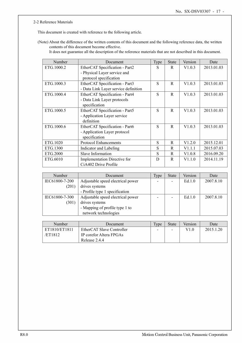
2-2 Reference Materials
This document is created with reference to the following article. (Note) About the difference of the written contents of this document and the following reference data, the written
contents of this document become effective. It does not guarantee all the description of the reference materials that are not described in this document.
Number Document Type State Version Date
ETG.1000.2 EtherCAT Specification - Part2 - Physical Layer service and protocol specification
S R V1.0.3 2013.01.03
ETG.1000.3 EtherCAT Specification - Part3 - Data Link Layer service definition
S R V1.0.3 2013.01.03
ETG.1000.4 EtherCAT Specification - Part4 - Data Link Layer protocols specification
S R V1.0.3 2013.01.03
ETG.1000.5 EtherCAT Specification - Part5 - Application Layer service definition
S R V1.0.3 2013.01.03
ETG.1000.6 EtherCAT Specification - Part6 - Application Layer protocol specification
S R V1.0.3 2013.01.03
ETG.1020 Protocol Enhancements S R V1.2.0 2015.12.01 ETG.1300 Indicator and Labeling S R V1.1.1 2015.07.03 ETG.2000 Slave Information S R V1.0.8 2016.09.20 ETG.6010 Implementation Directive for
CiA402 Drive Profile D R V1.1.0 2014.11.19
Number Document Type State Version Date
IEC61800-7-200 (201)
Adjustable speed electrical power drives systems - Profile type 1 specification
- - Ed.1.0 2007.8.10
IEC61800-7-300 (301)
Adjustable speed electrical power drives systems - Mapping of profile type 1 to network technologies
- - Ed.1.0 2007.8.10
Number Document Type State Version Date
ET1810/ET1811 /ET1812
EtherCAT Slave Controller IP corefor Altera FPGAs Release 2.4.4
- - V1.0 2015.1.20
No. SX-DSV03307 - 18 -
R8.0 Motion Control Business Unit, Panasonic Corporation
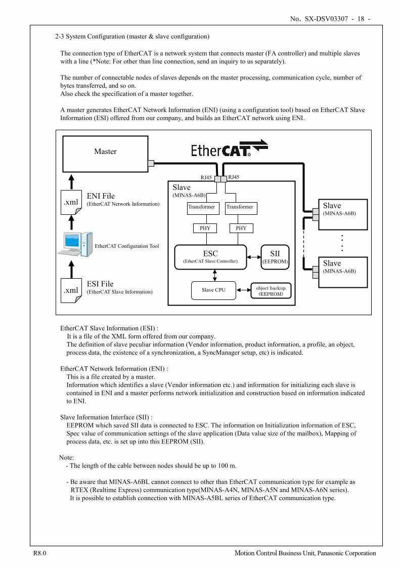
2-3 System Configuration (master & slave configuration)
The connection type of EtherCAT is a network system that connects master (FA controller) and multiple slaves with a line (*Note: For other than line connection, send an inquiry to us separately). The number of connectable nodes of slaves depends on the master processing, communication cycle, number of bytes transferred, and so on. Also check the specification of a master together. A master generates EtherCAT Network Information (ENI) (using a configuration tool) based on EtherCAT Slave Information (ESI) offered from our company, and builds an EtherCAT network using ENI.
EtherCAT Slave Information (ESI) :
It is a file of the XML form offered from our company. The definition of slave peculiar information (Vendor information, product information, a profile, an object, process data, the existence of a synchronization, a SyncManager setup, etc) is indicated.
EtherCAT Network Information (ENI) :
This is a file created by a master. Information which identifies a slave (Vendor information etc.) and information for initializing each slave is contained in ENI and a master performs network initialization and construction based on information indicated to ENI.
Slave Information Interface (SII) :
EEPROM which saved SII data is connected to ESC. The information on Initialization information of ESC, Spec value of communication settings of the slave application (Data value size of the mailbox), Mapping of process data, etc. is set up into this EEPROM (SII).
Note:
- The length of the cable between nodes should be up to 100 m. - Be aware that MINAS-A6BL cannot connect to other than EtherCAT communication type for example as
RTEX (Realtime Express) communication type(MINAS-A4N, MINAS-A5N and MINAS-A6N series). It is possible to establish connection with MINAS-A5BL series of EtherCAT communication type.
Slave (MINAS-A6B)
Master
Slave (MINAS-A6B)
ENI File (EtherCAT Network Information)
.xml
: :
ESI File (EtherCAT Slave Information)
Transformer Transformer
PHY PHY
ESC (EtherCAT Slave Controller)
SII (EEPROM)
Slave CPU
RJ45 RJ45
.xml
Slave (MINAS-A6B)
: EtherCAT Configuration Tool
object backup (EEPROM)
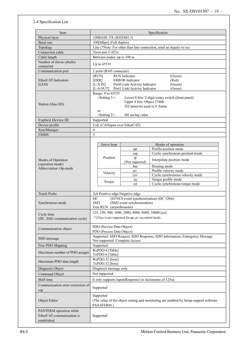
No. SX-DSV03307 - 19 -
R8.0 Motion Control Business Unit, Panasonic Corporation
2-4 Specification List
Item Specification
Physical layer 100BASE-TX (IEEE802.3) Baud rate 100[Mbps] (Full duplex) Topology Line (*Note: For other than line connection, send an inquiry to us) Connection cable Twist pair CAT5e Cable length Between nodes: up to 100 m Number of slaves (shafts) connected Up to 65535
Communication port 2 ports (RJ45 connector)
EtherCAT Indicators (LED)
[RUN] RUN Indicator (Green) [ERR] ERROR Indicator (Red) [L/A IN] Port0 Link/Activity Indicator (Green) [L/A OUT] Port1 Link/Activity Indicator (Green)
Station Alias (ID)
Range: 0 to 65535 <Setting 1>: Lower 8 bits: 2-digit rotary switch (front panel)
Upper 8 bits: Object 3740h ※Cannot be used in V frame
or <Setting 2>: SII saving value
Explicit Device ID Supported Device profile CoE (CANopen over EtherCAT) SyncManager 4 FMMU 3
Modes of Operation (operation mode) Abbreviation: Op-mode
Servo loop Modes of operation
Position
pp Profile position mode csp Cyclic synchronous position mode ip
(Not supported) Interpolate position mode
hm Homing mode
Velocity pv Profile velocity mode csv Cyclic synchronous velocity mode
Torque tq Torque profile mode cst Cyclic synchronous torque mode
Touch Probe 2ch Positive edge/Negative edge
Synchronous mode DC (SYNC0 event synchronization) (DC 32bit) SM2 (SM2 event synchronization) Free RUN (asynchronous)
Cycle time (DC, SM2 communication cycle)
125, 250, 500, 1000, 2000, 4000, 8000, 10000 [µs] *125µs is not supported for pp, pv, tq control mode.
Communication object SDO (Service Data Object) PDO (Process Data Object)
SDO message Supported: SDO Request, SDO Response, SDO information, Emergency Message Not supported: Complete Access
Free PDO Mapping Supported
Maximum number of PDO assigns RxPDO:4 [Table] TxPDO:4 [Table]
Maximum PDO data length RxPDO:32 [byte] TxPDO:32 [byte]
Diagnosis Object Diagnosis message only Command Object Not supported
Shift time It only supports Input(Response) in increments of 125us. Communication error correction of csp
Supported
Object Editor Supported (The value of the object setting and monitoring are enabled by Setup support software PANATERM.)
PANTERM operation while EtherCAT communication is established
Supported
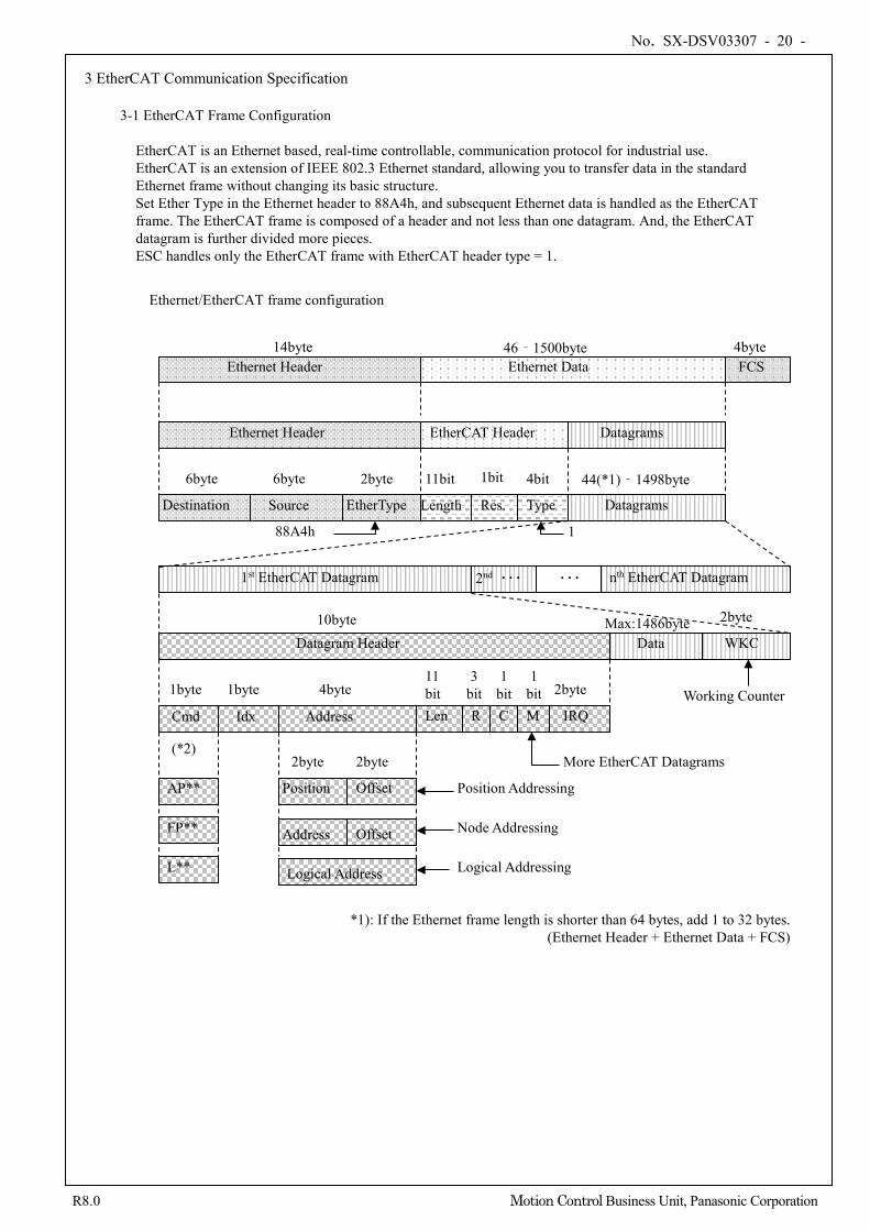
No. SX-DSV03307 - 20 -
R8.0 Motion Control Business Unit, Panasonic Corporation
3 EtherCAT Communication Specification
3-1 EtherCAT Frame Configuration
EtherCAT is an Ethernet based, real-time controllable, communication protocol for industrial use. EtherCAT is an extension of IEEE 802.3 Ethernet standard, allowing you to transfer data in the standard Ethernet frame without changing its basic structure. Set Ether Type in the Ethernet header to 88A4h, and subsequent Ethernet data is handled as the EtherCAT frame. The EtherCAT frame is composed of a header and not less than one datagram. And, the EtherCAT datagram is further divided more pieces. ESC handles only the EtherCAT frame with EtherCAT header type = 1.
Ethernet/EtherCAT frame configuration
Ethernet Header Ethernet Data FCS
Destination Source EtherType Length Res. Type Datagrams
1st EtherCAT Datagram 2nd ・・・ ・・・ nth EtherCAT Datagram
Datagram Header Data WKC
Cmd Idx Address Len R C M IRQ
Position Offset
Address Offset
Logical Address
14byte
44(*1)‐1498byte
4byte
6byte 6byte 2byte 11bit 1bit 4bit
10byte Max:1486byte 2byte
1byte 1byte 4byte 11 bit
3 bit
1 bit
1 bit 2byte
2byte 2byte
46‐1500byte
Working Counter
More EtherCAT Datagrams
Position Addressing
Node Addressing
Logical Addressing
*1): If the Ethernet frame length is shorter than 64 bytes, add 1 to 32 bytes. (Ethernet Header + Ethernet Data + FCS)
88A4h 1
Ethernet Header EtherCAT Header Datagrams
AP**
FP**
L**
(*2)
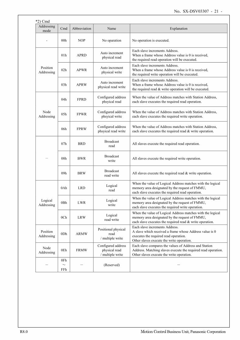
No. SX-DSV03307 - 21 -
R8.0 Motion Control Business Unit, Panasonic Corporation
*2) Cmd
Addressing mode Cmd Abbreviation Name Explanation
- 00h NOP No oparation No operation is executed.
Position Addressing
01h APRD Auto increment physical read
Each slave increments Address. When a frame whose Address value is 0 is received, the required read operation will be executed.
02h APWR Auto increment physical write
Each slave increments Address. When a frame whose Address value is 0 is received, the required write operation will be executed.
03h APRW Auto increment physical read write
Each slave increments Address. When a frame whose Address value is 0 is received, the required read & write operation will be executed.
Node Addressing
04h FPRD Configured address phsyical read
When the value of Address matches with Station Address, each slave executes the required read operation.
05h FPWR Configured address phsyical write
When the value of Address matches with Station Address, each slave executes the required write operation.
06h FPRW Configured address phsyical read write
When the value of Address matches with Station Address, each slave executes the required read & write operation.
-
07h BRD Broadcast read All slaves execute the required read operation.
08h BWR Broadcast write All slaves execute the required write operation.
09h BRW Broadcast read write All slaves execute the required read & write operation.
Logical Addressing
0Ah LRD Logical read
When the value of Logical Address matches with the logical memory area designated by the request of FMMU, each slave executes the required read operation.
0Bh LWR Logical write
When the value of Logical Address matches with the logical memory area designated by the request of FMMU, each slave executes the required write operation.
0Ch LRW Logical read write
When the value of Logical Address matches with the logical memory area designated by the request of FMMU, each slave executes the required read & write operation.
Position Addressing 0Dh ARMW
Positional physical read
/ multiple write
Each slave increments Address. A slave which received a frame whose Address value is 0 executes the required read operation. Other slaves execute the write operation.
Node Addressing 0Eh FRMW
Configured address physical read
/ multiple write
Each slave compares the values of Address and Station Address. Matching slaves execute the required read operation. Other slaves execute the write operation.
- 0Fh ~
FFh - (Reserved) -
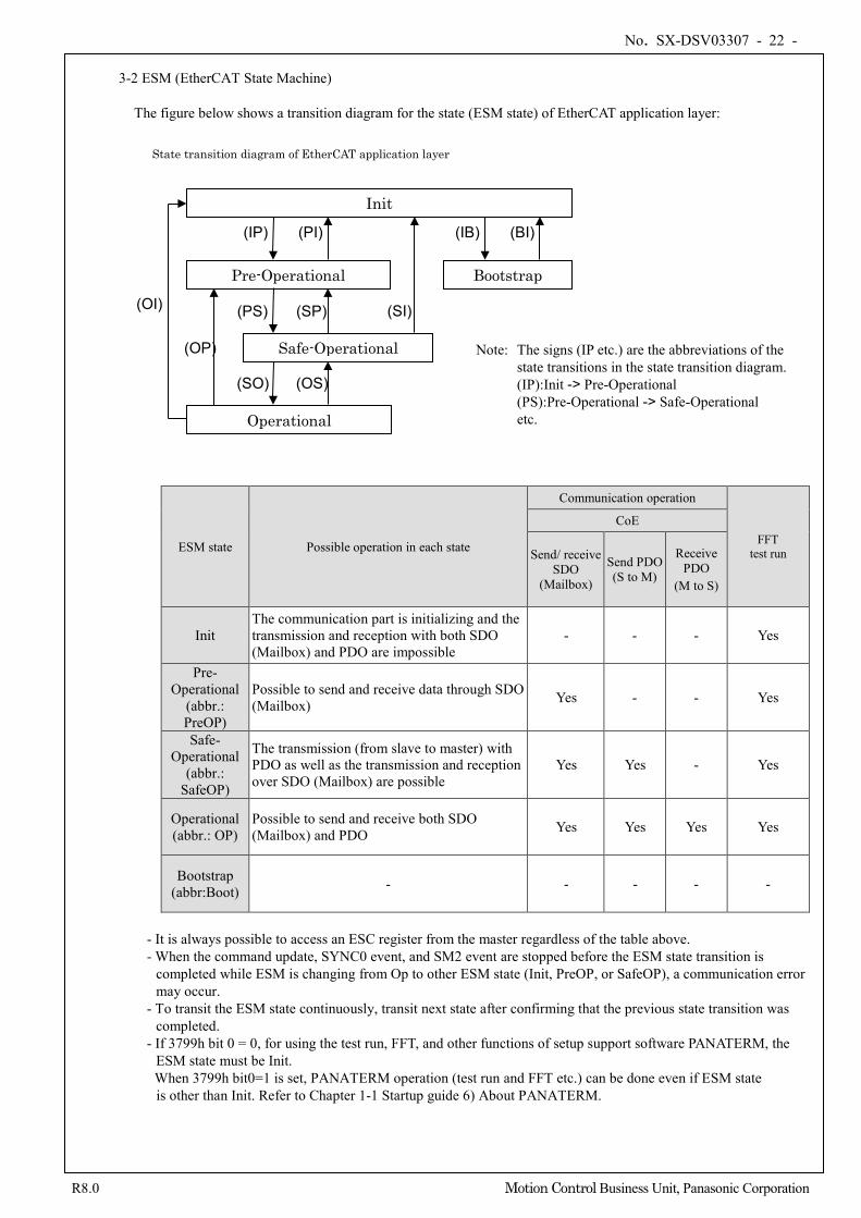
No. SX-DSV03307 - 22 -
R8.0 Motion Control Business Unit, Panasonic Corporation
3-2 ESM (EtherCAT State Machine)
The figure below shows a transition diagram for the state (ESM state) of EtherCAT application layer:
ESM state Possible operation in each state
Communication operation
FFT test run
CoE
Send/ receive SDO
(Mailbox)
Send PDO (S to M)
Receive PDO
(M to S)
Init The communication part is initializing and the transmission and reception with both SDO (Mailbox) and PDO are impossible
- - - Yes
Pre-Operational
(abbr.: PreOP)
Possible to send and receive data through SDO (Mailbox) Yes - - Yes
Safe-Operational
(abbr.: SafeOP)
The transmission (from slave to master) with PDO as well as the transmission and reception over SDO (Mailbox) are possible
Yes Yes - Yes
Operational (abbr.: OP)
Possible to send and receive both SDO (Mailbox) and PDO Yes Yes Yes Yes
Bootstrap (abbr:Boot) - - - - -
- It is always possible to access an ESC register from the master regardless of the table above. - When the command update, SYNC0 event, and SM2 event are stopped before the ESM state transition is
completed while ESM is changing from Op to other ESM state (Init, PreOP, or SafeOP), a communication error may occur.
- To transit the ESM state continuously, transit next state after confirming that the previous state transition was completed.
- If 3799h bit 0 = 0, for using the test run, FFT, and other functions of setup support software PANATERM, the ESM state must be Init. When 3799h bit0=1 is set, PANATERM operation (test run and FFT etc.) can be done even if ESM state is other than Init. Refer to Chapter 1-1 Startup guide 6) About PANATERM.
Safe-Operational
Pre-Operational
Init
(OI)
(OP)
(IP) (PI)
(OS)
(PS)
(SO)
(SP)
Operational
(SI)
State transition diagram of EtherCAT application layer
Bootstrap
(IB) (BI)
Note: The signs (IP etc.) are the abbreviations of the state transitions in the state transition diagram. (IP):Init -> Pre-Operational (PS):Pre-Operational -> Safe-Operational etc.
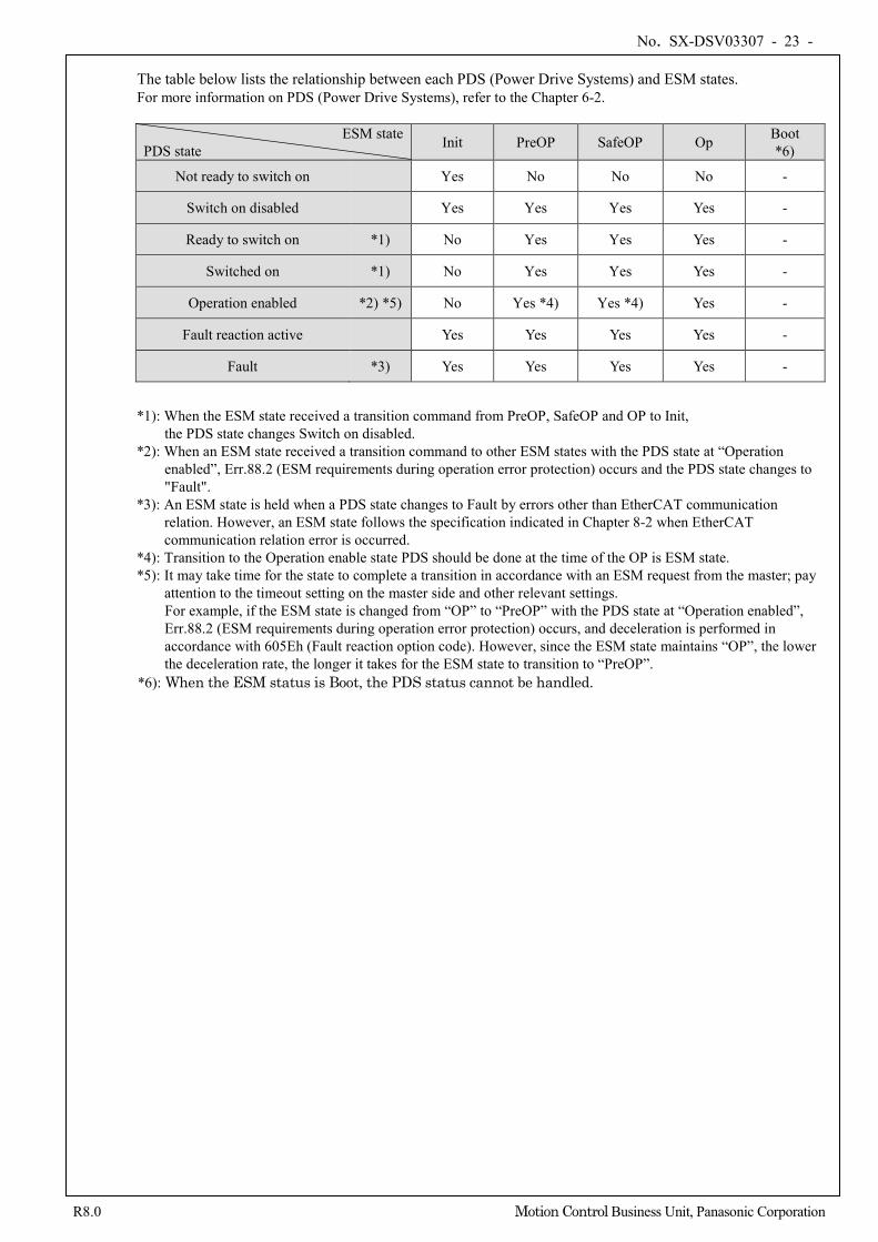
No. SX-DSV03307 - 23 -
R8.0 Motion Control Business Unit, Panasonic Corporation
The table below lists the relationship between each PDS (Power Drive Systems) and ESM states. For more information on PDS (Power Drive Systems), refer to the Chapter 6-2.
ESM state PDS state Init PreOP SafeOP Op Boot
*6)
Not ready to switch on Yes No No No -
Switch on disabled Yes Yes Yes Yes -
Ready to switch on *1) No Yes Yes Yes -
Switched on *1) No Yes Yes Yes -
Operation enabled *2) *5) No Yes *4) Yes *4) Yes -
Fault reaction active Yes Yes Yes Yes -
Fault *3) Yes Yes Yes Yes -
*1): When the ESM state received a transition command from PreOP, SafeOP and OP to Init,
the PDS state changes Switch on disabled. *2): When an ESM state received a transition command to other ESM states with the PDS state at “Operation
enabled”, Err.88.2 (ESM requirements during operation error protection) occurs and the PDS state changes to "Fault".
*3): An ESM state is held when a PDS state changes to Fault by errors other than EtherCAT communication relation. However, an ESM state follows the specification indicated in Chapter 8-2 when EtherCAT communication relation error is occurred.
*4): Transition to the Operation enable state PDS should be done at the time of the OP is ESM state. *5): It may take time for the state to complete a transition in accordance with an ESM request from the master; pay
attention to the timeout setting on the master side and other relevant settings. For example, if the ESM state is changed from “OP” to “PreOP” with the PDS state at “Operation enabled”, Err.88.2 (ESM requirements during operation error protection) occurs, and deceleration is performed in accordance with 605Eh (Fault reaction option code). However, since the ESM state maintains “OP”, the lower the deceleration rate, the longer it takes for the ESM state to transition to “PreOP”.
*6): When the ESM status is Boot, the PDS status cannot be handled.
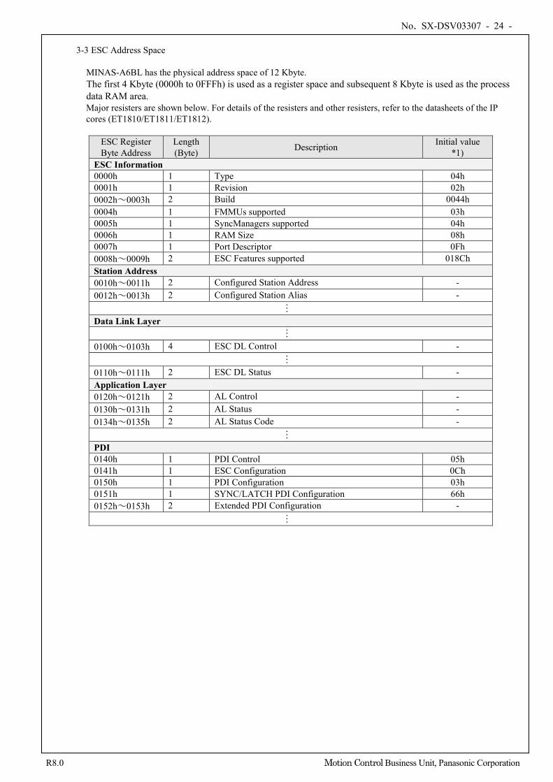
No. SX-DSV03307 - 24 -
R8.0 Motion Control Business Unit, Panasonic Corporation
3-3 ESC Address Space
MINAS-A6BL has the physical address space of 12 Kbyte. The first 4 Kbyte (0000h to 0FFFh) is used as a register space and subsequent 8 Kbyte is used as the process data RAM area. Major resisters are shown below. For details of the resisters and other resisters, refer to the datasheets of the IP cores (ET1810/ET1811/ET1812).
ESC Register Byte Address
Length (Byte) Description Initial value
*1) ESC Information 0000h 1 Type 04h 0001h 1 Revision 02h 0002h~0003h 2 Build 0044h 0004h 1 FMMUs supported 03h 0005h 1 SyncManagers supported 04h 0006h 1 RAM Size 08h 0007h 1 Port Descriptor 0Fh 0008h~0009h 2 ESC Features supported 018Ch Station Address 0010h~0011h 2 Configured Station Address - 0012h~0013h 2 Configured Station Alias - …
Data Link Layer …
0100h~0103h 4 ESC DL Control - …
0110h~0111h 2 ESC DL Status - Application Layer 0120h~0121h 2 AL Control - 0130h~0131h 2 AL Status - 0134h~0135h 2 AL Status Code - …
PDI 0140h 1 PDI Control 05h 0141h 1 ESC Configuration 0Ch 0150h 1 PDI Configuration 03h 0151h 1 SYNC/LATCH PDI Configuration 66h 0152h~0153h 2 Extended PDI Configuration - …
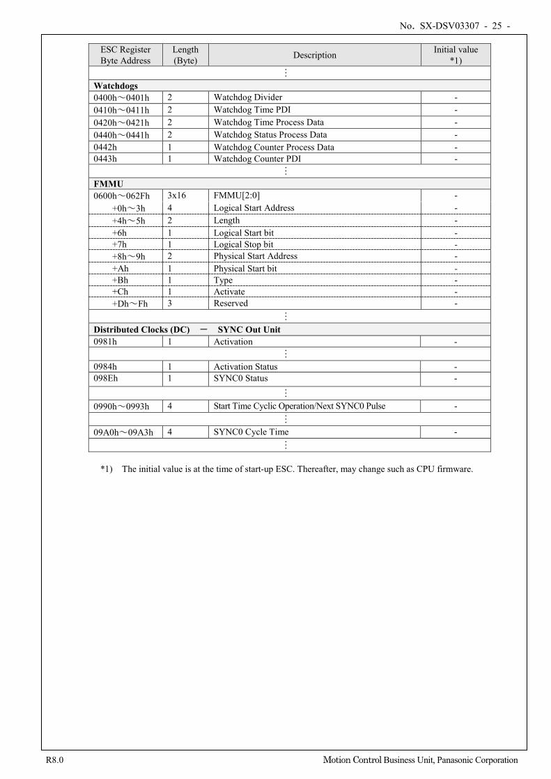
No. SX-DSV03307 - 25 -
R8.0 Motion Control Business Unit, Panasonic Corporation
ESC Register Byte Address
Length (Byte) Description Initial value
*1) …
Watchdogs 0400h~0401h 2 Watchdog Divider - 0410h~0411h 2 Watchdog Time PDI - 0420h~0421h 2 Watchdog Time Process Data - 0440h~0441h 2 Watchdog Status Process Data - 0442h 1 Watchdog Counter Process Data - 0443h 1 Watchdog Counter PDI - …
FMMU 0600h~062Fh 3x16 FMMU[2:0] - +0h~3h 4 Logical Start Address - +4h~5h 2 Length - +6h 1 Logical Start bit - +7h 1 Logical Stop bit - +8h~9h 2 Physical Start Address - +Ah 1 Physical Start bit - +Bh 1 Type - +Ch 1 Activate - +Dh~Fh 3 Reserved - …
Distributed Clocks (DC) - SYNC Out Unit 0981h 1 Activation - …
0984h 1 Activation Status - 098Eh 1 SYNC0 Status -
…
0990h~0993h 4 Start Time Cyclic Operation/Next SYNC0 Pulse - …
09A0h~09A3h 4 SYNC0 Cycle Time - …
*1) The initial value is at the time of start-up ESC. Thereafter, may change such as CPU firmware.
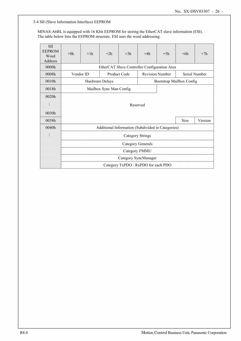
No. SX-DSV03307 - 26 -
R8.0 Motion Control Business Unit, Panasonic Corporation
3-4 SII (Slave Information Interface) EEPROM
MINAS-A6BL is equipped with 16 Kbit EEPROM for storing the EtherCAT slave information (ESI). The table below lists the EEPROM structure. ESI uses the word addressing.
SII EEPROM
Word Address
+0h +1h +2h +3h +4h +5h +6h +7h
0000h EtherCAT Slave Controller Configuration Area
0008h Vendor ID Product Code Revision Number Serial Number
0010h Hardware Delays Bootstrap Mailbox Config
0018h Mailbox Sync Man Config
0020h
Reserved
...
0030h
0038h Size Version
0040h Additional Information (Subdivided in Categories)
... Category Strings
Category Generals
Category FMMU
Category SyncManager
Category TxPDO / RxPDO for each PDO
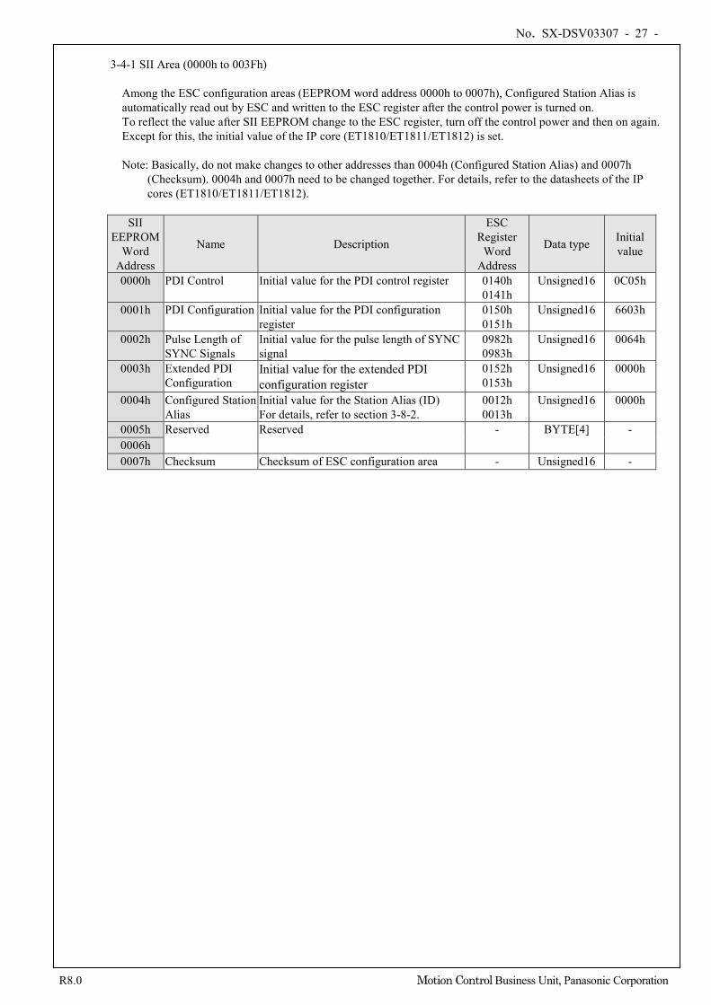
No. SX-DSV03307 - 27 -
R8.0 Motion Control Business Unit, Panasonic Corporation
3-4-1 SII Area (0000h to 003Fh)
Among the ESC configuration areas (EEPROM word address 0000h to 0007h), Configured Station Alias is automatically read out by ESC and written to the ESC register after the control power is turned on. To reflect the value after SII EEPROM change to the ESC register, turn off the control power and then on again. Except for this, the initial value of the IP core (ET1810/ET1811/ET1812) is set. Note: Basically, do not make changes to other addresses than 0004h (Configured Station Alias) and 0007h
(Checksum). 0004h and 0007h need to be changed together. For details, refer to the datasheets of the IP cores (ET1810/ET1811/ET1812).
SII
EEPROM Word
Address
Name Description
ESC Register
Word Address
Data type Initial value
0000h PDI Control Initial value for the PDI control register 0140h 0141h
Unsigned16 0C05h
0001h PDI Configuration Initial value for the PDI configuration register
0150h 0151h
Unsigned16 6603h
0002h Pulse Length of SYNC Signals
Initial value for the pulse length of SYNC signal
0982h 0983h
Unsigned16 0064h
0003h Extended PDI Configuration
Initial value for the extended PDI configuration register
0152h 0153h
Unsigned16 0000h
0004h Configured Station Alias
Initial value for the Station Alias (ID) For details, refer to section 3-8-2.
0012h 0013h
Unsigned16 0000h
0005h Reserved Reserved - BYTE[4] - 0006h 0007h Checksum Checksum of ESC configuration area - Unsigned16 -
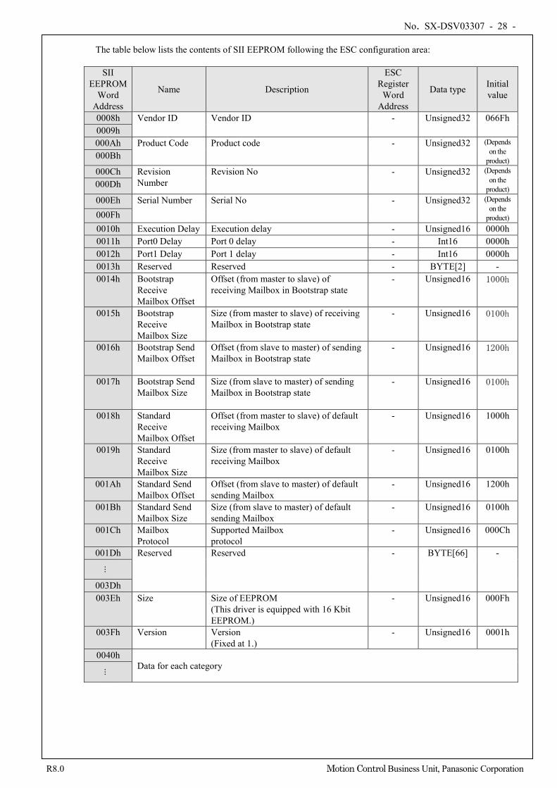
No. SX-DSV03307 - 28 -
R8.0 Motion Control Business Unit, Panasonic Corporation
The table below lists the contents of SII EEPROM following the ESC configuration area:
SII EEPROM
Word Address
Name Description
ESC Register
Word Address
Data type Initial value
0008h Vendor ID Vendor ID - Unsigned32 066Fh 0009h 000Ah Product Code Product code - Unsigned32 (Depends
on the product) 000Bh
000Ch Revision Number
Revision No - Unsigned32 (Depends on the
product) 000Dh
000Eh Serial Number Serial No - Unsigned32 (Depends on the
product) 000Fh 0010h Execution Delay Execution delay - Unsigned16 0000h 0011h Port0 Delay Port 0 delay - Int16 0000h 0012h Port1 Delay Port 1 delay - Int16 0000h 0013h Reserved Reserved - BYTE[2] - 0014h Bootstrap
Receive Mailbox Offset
Offset (from master to slave) of receiving Mailbox in Bootstrap state
- Unsigned16 1000h
0015h Bootstrap Receive Mailbox Size
Size (from master to slave) of receiving Mailbox in Bootstrap state
- Unsigned16 0100h
0016h Bootstrap Send Mailbox Offset
Offset (from slave to master) of sending Mailbox in Bootstrap state
- Unsigned16 1200h
0017h Bootstrap Send Mailbox Size
Size (from slave to master) of sending Mailbox in Bootstrap state
- Unsigned16 0100h
0018h Standard Receive Mailbox Offset
Offset (from master to slave) of default receiving Mailbox
- Unsigned16 1000h
0019h Standard Receive Mailbox Size
Size (from master to slave) of default receiving Mailbox
- Unsigned16 0100h
001Ah Standard Send Mailbox Offset
Offset (from slave to master) of default sending Mailbox
- Unsigned16 1200h
001Bh Standard Send Mailbox Size
Size (from slave to master) of default sending Mailbox
- Unsigned16 0100h
001Ch Mailbox Protocol
Supported Mailbox protocol
- Unsigned16 000Ch
001Dh Reserved Reserved - BYTE[66] -
...
003Dh 003Eh Size Size of EEPROM
(This driver is equipped with 16 Kbit EEPROM.)
- Unsigned16 000Fh
003Fh Version Version (Fixed at 1.)
- Unsigned16 0001h
0040h Data for each category ...
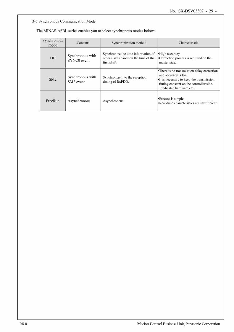
No. SX-DSV03307 - 29 -
R8.0 Motion Control Business Unit, Panasonic Corporation
3-5 Synchronous Communication Mode
The MINAS-A6BL series enables you to select synchronous modes below:
Synchronous mode Contents Synchronization method Characteristic
DC Synchronous with SYNC0 event
Synchronize the time information of other slaves based on the time of the first shaft.
• High accuracy • Correction process is required on the master side.
SM2 Synchronous with SM2 event
Synchronize it to the reception timing of RxPDO.
• There is no transmission delay correction and accuracy is low.
• It is necessary to keep the transmission timing constant on the controller side.
(dedicated hardware etc.)
FreeRun Asynchronous Asynchronous • Process is simple. • Real-time characteristics are insufficient.
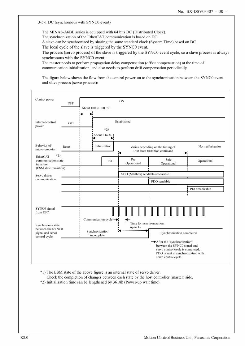
No. SX-DSV03307 - 30 -
R8.0 Motion Control Business Unit, Panasonic Corporation
3-5-1 DC (synchronous with SYNC0 event)
The MINAS-A6BL series is equipped with 64 bits DC (Distributed Clock). The synchronization of the EtherCAT communication is based on DC. A slave can be synchronized by sharing the same standard clock (System Time) based on DC. The local cycle of the slave is triggered by the SYNC0 event. The process (servo process) of the slave is triggered by the SYNC0 event cycle, so a slave process is always synchronous with the SYNC0 event. The master needs to perform propagation delay compensation (offset compensation) at the time of communication initialization, and also needs to perform drift compensation periodically. The figure below shows the flow from the control power-on to the synchronization between the SYNC0 event and slave process (servo process):
*1) The ESM state of the above figure is an internal state of servo driver. Check the completion of changes between each state by the host controller (master) side.
*2) Initialization time can be lengthened by 3618h (Power-up wait time).
Behavior of microcomputer
Internal control power
Control power
Initialization
About.2 to 3s
OFF
OFF
About 100 to 300 ms
ON
Established
Normal behavior Reset
Time for synchronization: up to 1s
Synchronization incomplete
Synchronization completed
EtherCAT communication state transition (ESM state transition)
Init Pre Operational
Safe Operational
Operational
SYNC0 signal from ESC
Communication cycle
Synchronous state between the SYNC0 signal and servo control cycle
Servo driver communication
PDO receivable
Varies depending on the timing of ESM state transition command
After the "synchronization" between the SYNC0 signal and servo control cycle is completed, PDO is sent in synchronization with servo control cycle.
SDO (Mailbox) sendable/receivable
PDO sendable
*1)
*2)
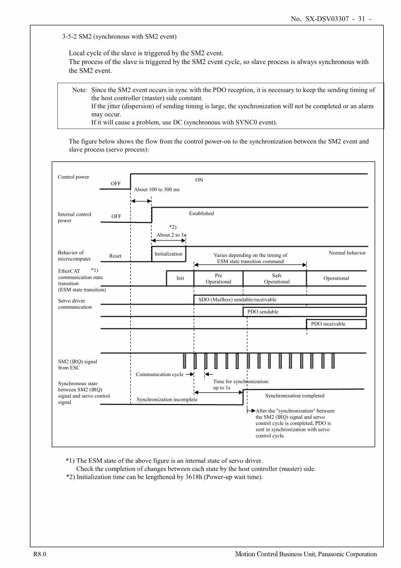
No. SX-DSV03307 - 31 -
R8.0 Motion Control Business Unit, Panasonic Corporation
3-5-2 SM2 (synchronous with SM2 event)
Local cycle of the slave is triggered by the SM2 event. The process of the slave is triggered by the SM2 event cycle, so slave process is always synchronous with the SM2 event.
Note: Since the SM2 event occurs in sync with the PDO reception, it is necessary to keep the sending timing of the host controller (master) side constant. If the jitter (dispersion) of sending timing is large, the synchronization will not be completed or an alarm may occur. If it will cause a problem, use DC (synchronous with SYNC0 event).
The figure below shows the flow from the control power-on to the synchronization between the SM2 event and slave process (servo process):
*1) The ESM state of the above figure is an internal state of servo driver. Check the completion of changes between each state by the host controller (master) side.
*2) Initialization time can be lengthened by 3618h (Power-up wait time).
Behavior of microcomputer
Internal control power
Control power
Initialization
About.2 to 3s
OFF
OFF
About 100 to 300 ms
ON
Established
Normal behavior Reset
Time for synchronization: up to 1s
Synchronization incomplete Synchronization completed
EtherCAT communication state transition (ESM state transition)
Init Pre Operational
Safe Operational Operational
SM2 (IRQ) signal from ESC
Communication cycle
Synchronous state between SM2 (IRQ) signal and servo control signal
Servo driver communication
PDO receivable
Varies depending on the timing of ESM state transition command
SDO (Mailbox) sendable/receivable
PDO sendable
After the "synchronization" between the SM2 (IRQ) signal and servo control cycle is completed, PDO is sent in synchronization with servo control cycle.
*1)
*2)
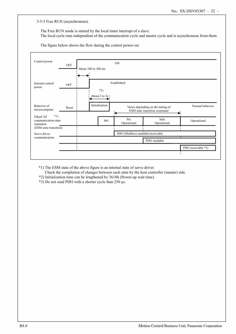
No. SX-DSV03307 - 32 -
R8.0 Motion Control Business Unit, Panasonic Corporation
3-5-3 Free RUN (asynchronous)
The Free RUN mode is started by the local timer interrupt of a slave. The local cycle runs independent of the communication cycle and master cycle and is asynchronous from them. The figure below shows the flow during the control power-on:
*1) The ESM state of the above figure is an internal state of servo driver. Check the completion of changes between each state by the host controller (master) side.
*2) Initialization time can be lengthened by 3618h (Power-up wait time). *3) Do not send PDO with a shorter cycle than 250 μs.
Behavior of microcomputer
Internal control power
Control power
Initialization
About.2 to 3s
OFF
OFF
About 100 to 300 ms
ON
Established
Normal behavior Reset
EtherCAT communication state transition (ESM state transition)
Init Pre Operational
Safe Operational
Operational
Servo driver communication
PDO receivable *3)
Varies depending on the timing of ESM state transition command
SDO (Mailbox) sendable/receivable
PDO sendable
*1)
*2)
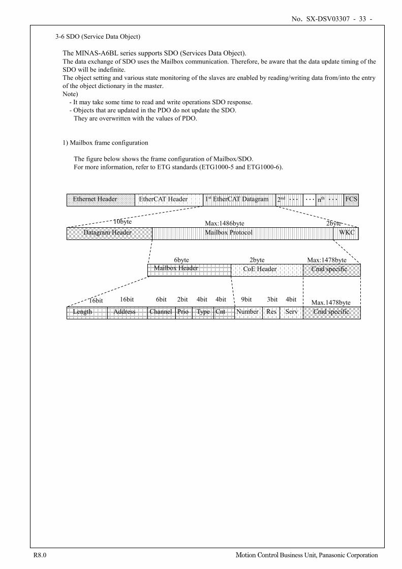
No. SX-DSV03307 - 33 -
R8.0 Motion Control Business Unit, Panasonic Corporation
3-6 SDO (Service Data Object)
The MINAS-A6BL series supports SDO (Services Data Object). The data exchange of SDO uses the Mailbox communication. Therefore, be aware that the data update timing of the SDO will be indefinite. The object setting and various state monitoring of the slaves are enabled by reading/writing data from/into the entry of the object dictionary in the master. Note)
- It may take some time to read and write operations SDO response. - Objects that are updated in the PDO do not update the SDO.
They are overwritten with the values of PDO. 1) Mailbox frame configuration
The figure below shows the frame configuration of Mailbox/SDO. For more information, refer to ETG standards (ETG1000-5 and ETG1000-6).
Ethernet Header FCS 1st EtherCAT Datagram 2nd ・・・ ・・・
Datagram Header Mailbox Protocol WKC
Length Address
10byte Max:1486byte 2byte
16bit 16bit 6bit 2bit 4bit 4bit Max.1478byte
EtherCAT Header nth ・・・
Channel Prio Type Cnt
9bit 3bit 4bit
Number Res Serv
CoE Header Mailbox Header Cmd specific
Cmd specific
6byte 2byte Max:1478byte
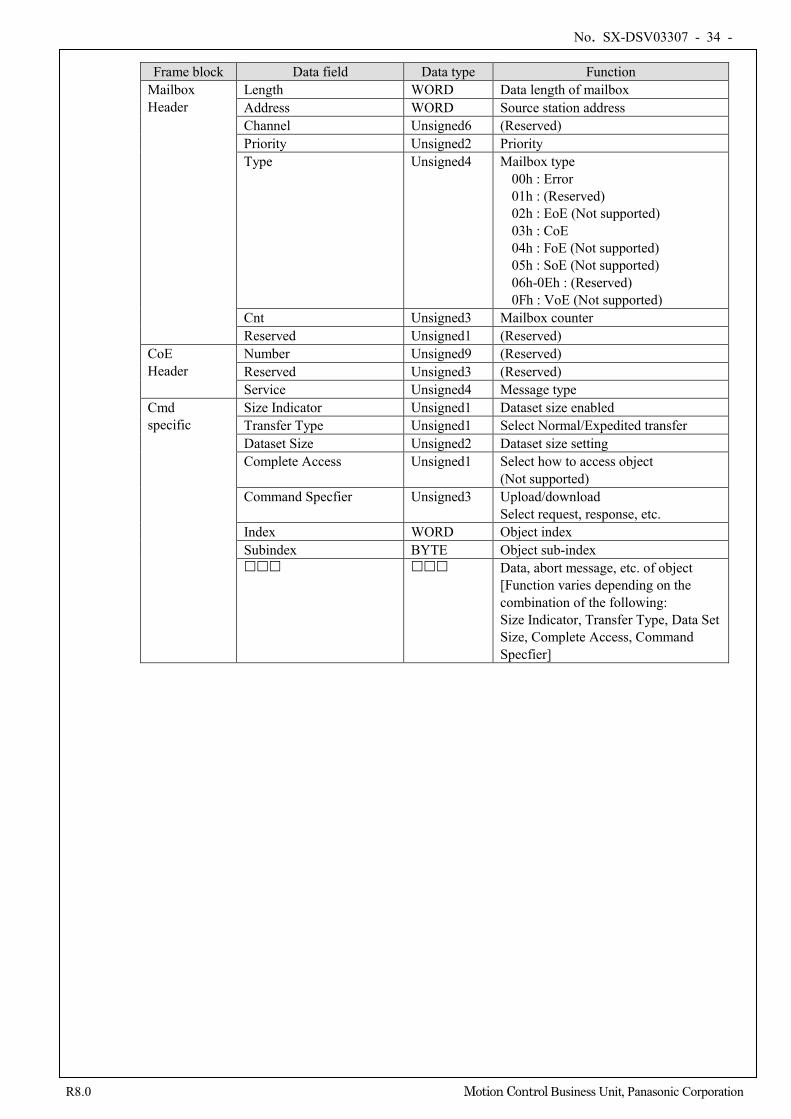
No. SX-DSV03307 - 34 -
R8.0 Motion Control Business Unit, Panasonic Corporation
Frame block Data field Data type Function
Mailbox Header
Length WORD Data length of mailbox Address WORD Source station address Channel Unsigned6 (Reserved) Priority Unsigned2 Priority Type Unsigned4 Mailbox type
00h : Error 01h : (Reserved) 02h : EoE (Not supported) 03h : CoE 04h : FoE (Not supported) 05h : SoE (Not supported) 06h-0Eh : (Reserved) 0Fh : VoE (Not supported)
Cnt Unsigned3 Mailbox counter Reserved Unsigned1 (Reserved)
CoE Header
Number Unsigned9 (Reserved) Reserved Unsigned3 (Reserved) Service Unsigned4 Message type
Cmd specific
Size Indicator Unsigned1 Dataset size enabled Transfer Type Unsigned1 Select Normal/Expedited transfer Dataset Size Unsigned2 Dataset size setting Complete Access Unsigned1 Select how to access object
(Not supported) Command Specfier Unsigned3 Upload/download
Select request, response, etc. Index WORD Object index Subindex BYTE Object sub-index Data, abort message, etc. of object
[Function varies depending on the combination of the following: Size Indicator, Transfer Type, Data Set Size, Complete Access, Command Specfier]
No. SX-DSV03307 - 35 -
R8.0 Motion Control Business Unit, Panasonic Corporation
2) Mailbox timeout
With this servo driver, the timeout time in Mailbox communication is set as follows:
- Timeout time for Mailbox request: 100 ms If the master transmits a request to the slave (driver) and WKC of transmission data of the request frame is updated, the request is considered to be properly received by the slave. Although retry operation is performed until WKC is updated, timeout occurs at the master side if WKC is not updated until this setting time expires.
- Timeout time for Mailbox response: 10 seconds
If the master receives a response to a request from the slave (driver) and WKC is updated, the response is considered to be properly received by the slave. Timeout occurs at the master side if the master does not receive a response where WKC is updated until this setting time expires. The maximum time required for the response creation of the slave (driver).
(Note) If the slave (driver) receives the same Mailbox counter continuously from the master, the slave suspends the
SDO reception process. To restart the SDO reception process, transition the ESM state from Init to PreOP again. *1)
*1) In the enhanced version 5 or later, even if the slave (driver) receives the same Mailbox counter,
the slave continue SDO reception process without transitioning the ESM state.
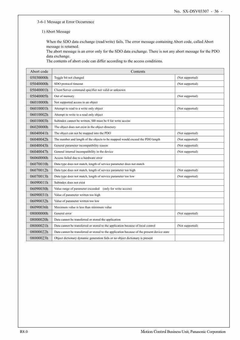
No. SX-DSV03307 - 36 -
R8.0 Motion Control Business Unit, Panasonic Corporation
3-6-1 Message at Error Occurrence
1) Abort Message
When the SDO data exchange (read/write) fails, The error message containing Abort code, called Abort message is returned. The abort message is an error only for the SDO data exchange. There is not any abort message for the PDO data exchange. The contents of abort code can differ according to the access conditions.
Abort code Contents 05030000h Toggle bit not changed (Not supported)
05040000h SDO protocol timeout (Not supported)
05040001h Client/Server command specifier not valid or unknown
05040005h Out of memory (Not supported)
06010000h Not supported access to an object
06010001h Attempt to read to a write only object (Not supported)
06010002h Attempt to write to a read only object
06010003h Subindex cannot be written, SI0 must be 0 for write access
06020000h The object does not exist in the object directory
06040041h The object can not be mapped into the PDO (Not supported)
06040042h The number and length of the objects to be mapped would exceed the PDO length (Not supported)
06040043h General parameter incompatibility reason (Not supported)
06040047h General internal incompatibility in the device (Not supported)
06060000h Access failed due to a hardware error
06070010h Data type does not match, length of service parameter does not match
06070012h Data type does not match, length of service parameter too high (Not supported)
06070013h Data type does not match, length of service parameter too low (Not supported)
06090011h Subindex does not exist
06090030h Value range of parameter exceeded (only for write access)
06090031h Value of parameter written too high
06090032h Value of parameter written too low
06090036h Maximum value is less than minimum value
08000000h General error (Not supported)
08000020h Data cannot be transferred or stored the application
08000021h Data cannot be transferred or stored to the application because of local control (Not supported)
08000022h Data cannot be transferred or stored to the application because of the present device state
08000023h Object dictionary dynamic generation fails or no object dictionary is present
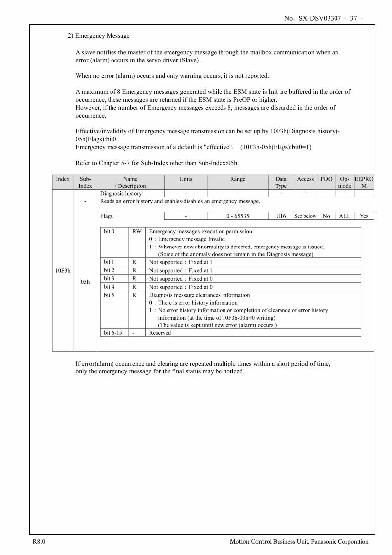
No. SX-DSV03307 - 37 -
R8.0 Motion Control Business Unit, Panasonic Corporation
2) Emergency Message
A slave notifies the master of the emergency message through the mailbox communication when an error (alarm) occurs in the servo driver (Slave). When no error (alarm) occurs and only warning occurs, it is not reported. A maximum of 8 Emergency messages generated while the ESM state is Init are buffered in the order of occurrence, these messages are returned if the ESM state is PreOP or higher. However, if the number of Emergency messages exceeds 8, messages are discarded in the order of occurrence. Effective/invalidity of Emergency message transmission can be set up by 10F3h(Diagnosis history)- 05h(Flags):bit0. Emergency message transmission of a default is "effective". (10F3h-05h(Flags):bit0=1) Refer to Chapter 5-7 for Sub-Index other than Sub-Index:05h.
Index Sub- Index
Name / Description
Units Range Data Type
Access PDO Op- mode
EEPROM
10F3h
- Diagnosis history - - - - - - - Reads an error history and enables/disables an emergency message.
05h
Flags - 0 - 65535 U16 See below No ALL Yes
bit 0 RW Emergency messages execution permission 0:Emergency message Invalid 1:Whenever new abnormality is detected, emergency message is issued.
(Some of the anomaly does not remain in the Diagnosis message) bit 1 R Not supported:Fixed at 1 bit 2 R Not supported:Fixed at 1 bit 3 R Not supported:Fixed at 0 bit 4 R Not supported:Fixed at 0 bit 5 R Diagnosis message clearances information
0:There is error history information 1:No error history information or completion of clearance of error history
information (at the time of 10F3h-03h=0 writing) (The value is kept until new error (alarm) occurs.)
bit 6-15 - Reserved
If error(alarm) occurrence and clearing are repeated multiple times within a short period of time, only the emergency message for the final status may be noticed.
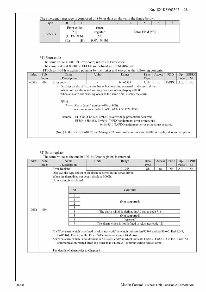
No. SX-DSV03307 - 38 -
R8.0 Motion Control Business Unit, Panasonic Corporation
The emergency message is composed of 8 bytes data as shown in the figure below:
Byte 0 1 2 3 4 5 6 7
Contents
Error code (*1)
(OD:603Fh)
Error register
(*2) (OD:1001h)
Error Field (*3)
(L) (H) *1) Error code
The same value as 603Fh(Error code) returns to Error code. The error codes at 0000h to FEFFh are defined in IEC61800-7-201. FF00h to FFFFh is defined peculiar by the maker and serves as the following contents.
Index Sub- Index
Name / Description
Units Range Data Type
Access PDO Op- mode
EEPROM
603Fh 00h Error code - 0 - 65535 U16 ro TxPDO ALL No • Displays an alarm (main number only) / warning occurred in the servo driver.
When both an alarm and warning does not occur, displays 0000h. When an alarm and warning occur at the same time, display the alarm.
FF**h
Alarm (main) number (00h to 9Fh) warning number(A0h to A9h, ACh, C3h,D2h, D3h)
Example: FF0Ch: 0Ch=12d. Err12.0 (over voltage protection) occurred
FF55h: 55h=85d. Err85.0 (TxPDO assignment error protection) or Err85.1 (RxPDO assignment error protection) occurred
(Note) In the case of Err81.7(SyncManager2/3 error protection) occurs, A000h is displayed as an exception.
*2) Error register
The same value as the one in 1001h (Error register) is returned. Index Sub-
Index Name
/ Description Units Range Data
Type Access PDO Op-
mode EEPRO
M
1001h 00h
Error Register - 0 - 255 U8 ro No ALL No Displays the type (state) of an alarm occurred in the servo driver. When an alarm does not occur, displays 0000h. No warning is displayed.
bit Contents
0
(Not supported) 1 2 3 4 The alarm which is defined in AL status code *1) 5 (Not supported) 6 (reserved) 7 The alarm which is not defined in AL status code *2)
*1) "The alarm which is defined in AL status code" is which indicate Err80.0-4 and Err80.6-7, Err81.0-7,
Err85.0-1, Err85.3 in the EtherCAT communication related error. *2) "The alarm which is not defined in AL status code" is which indicate Err85.2, Err88.0-3 in the EtherCAT
communication related error and other than EhterCAT communication related error. The details of alarm refer to Chapter 8.
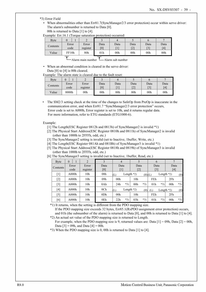
No. SX-DSV03307 - 39 -
R8.0 Motion Control Business Unit, Panasonic Corporation
*3) Error Field
• When abnormalities other than Err81.7(SyncManager2/3 error protection) occur within servo driver: The alarm's subnumber is returned to Data [0]. 00h is returned to Data [1] to [4].
Example: Err.16.1 (Torque saturation protection) occurred: Byte 0 1 2 3 4 5 6 7
Contents Error code
Error register
Data [0]
Data [1]
Data [2]
Data [3]
Data [4]
Value FF10h 80h 01h 00h 00h 00h 00h
• When an abnormal condition is cleared in the servo driver: Data [0] to [4] is 00h cleared.
Example: The alarm state is cleared due to the fault reset: Byte 0 1 2 3 4 5 6 7
Contents Error code
Error register
Data [0]
Data [1]
Data [2]
Data [3]
Data [4]
Value 0000h 00h 00h 00h 00h 00h 00h
• The SM2/3 setting check at the time of the changes to SafeOp from PreOp is inaccurate in the
communication error, and when Err81.7 “SyncManager2/3 error protection” occurs, Error code is set to A000h, Error register is set to 10h, and it returns regular data. For more information, refer to ETG standards (ETG1000-6).
Example: [1] The Length(ESC Register 0812h and 0813h) of SyncManager2 is invalid *1) [2] The Physical Start Address(ESC Register 0810h and 0811h) of SyncManager2 is invalid
(other than 1000h to 2FFFh, odd, etc.) [3] The SyncManager2 setting is invalid (set to Inactive, 1buffer, Write, etc.) [4] The Length(ESC Register 081Ah and 081Bh) of SyncManager3 is invalid *1) [5] The Physical Start Address(ESC Register 0818h and 0819h) of SyncManager3 is invalid
(other than 1000h to 2FFFh, odd, etc.) [6] The SyncManager3 setting is invalid (set to Inactive, 1buffer, Read, etc.)
Byte 0 1 2 3 4 5 6 7
Contents Error code
Error register
Data [0]
Data [1]
Data [2]
Data [3]
Data [4]
[1] A000h 10h 08h (L) Length *2) (H) (L) Length *2) (H) [2] A000h 10h 09h 00h 10h FEh 2Fh
[3] A000h 10h 0Ah 24h *3) 00h *3) 01h *3) 00h *3)
[4] A000h 10h 0Ch (L) Length *2) (H) (L) Length *2) (H) [5] A000h 10h 0Dh 00h 10h FEh 2Fh
[6] A000h 10h 0Eh 22h *3) 03h *3) 01h *3) 00h *3)
*1) It returns, when the setting is different from the PDO mapping size. If the PDO mapping size exceeds 32 bytes, Err85.1(RxPDO assignment error protection) occurs, and 01h (the subnumber of the alarm) is returned to Data [0], and 00h is returned to Data [1] to [4].
*2) An actual set value of the PDO mapping size is returned to Length. For example, when the PDO mapping size is 9, returned values are: Data [1] = 09h, Data [2] = 00h, Data [3] = 09h, and Data [4] = 00h.
*3) When the PDO mapping size is 0, 00h is returned to Data [1] to [4].
Alarm main number Alarm sub number
No. SX-DSV03307 - 40 -
R8.0 Motion Control Business Unit, Panasonic Corporation
3-7 PDO (Process Data Object)
The MINAS-A6BL series supports PDO (Process Data Object). The real time data transfer over EtherCAT is done by the data exchange with PDO (Process Data Object). PDO is composed of RxPDO transferring from master to slave and TxPDO transferring from slave to master.
Sender Receiver RxPDO Master Slave TxPDO Slave Master
(Note) The object updated by PDO should not carry out updating by SDO.
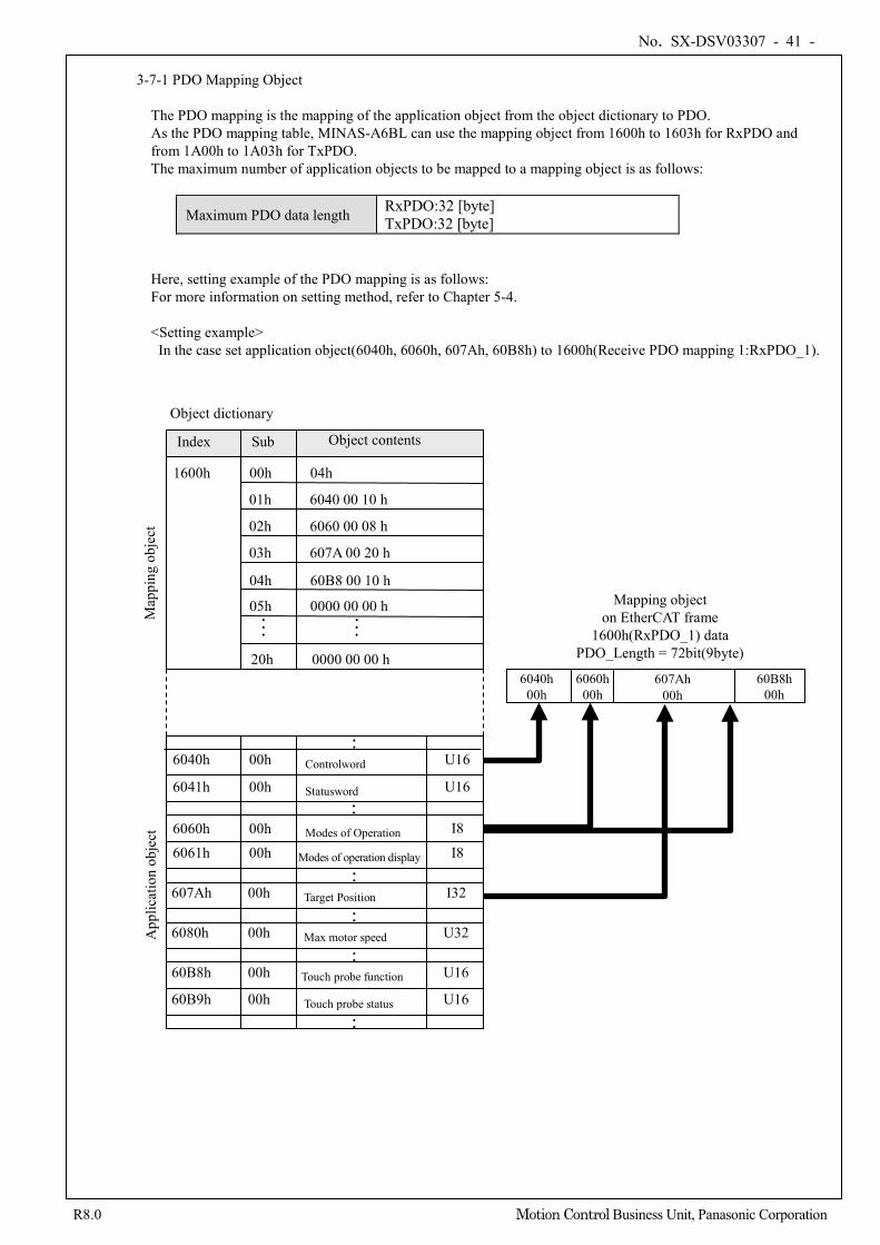
No. SX-DSV03307 - 41 -
R8.0 Motion Control Business Unit, Panasonic Corporation
3-7-1 PDO Mapping Object
The PDO mapping is the mapping of the application object from the object dictionary to PDO. As the PDO mapping table, MINAS-A6BL can use the mapping object from 1600h to 1603h for RxPDO and from 1A00h to 1A03h for TxPDO. The maximum number of application objects to be mapped to a mapping object is as follows:
Maximum PDO data length RxPDO:32 [byte] TxPDO:32 [byte]
Here, setting example of the PDO mapping is as follows: For more information on setting method, refer to Chapter 5-4. <Setting example>
In the case set application object(6040h, 6060h, 607Ah, 60B8h) to 1600h(Receive PDO mapping 1:RxPDO_1).
Index Sub Object contents
01h
02h
03h
6040 00 10 h
6060 00 08 h
607A 00 20 h
6040h 00h Controlword
6041h 00h Statusword
6060h 00h Modes of Operation
6061h 00h Modes of operation display
6040h 00h
6060h 00h
60B8h 00h
Object dictionary
Mapping object on EtherCAT frame
1600h(RxPDO_1) data PDO_Length = 72bit(9byte)
U16
U16
I8
I8
00h 04h 1600h
60B8 00 10 h 04h
20h 0000 00 00 h
・・・
・・・
0000 00 00 h 05h
607Ah 00h Target Position I32
6080h 00h Max motor speed U32
60B8h 00h Touch probe function U16
60B9h 00h Touch probe status U16
・・ ・・
・・ ・・
・・ ・・
607Ah 00h
App
licat
ion
obje
ct
Map
ping
obj
ect
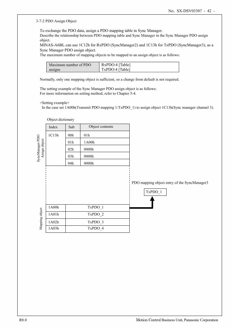
No. SX-DSV03307 - 42 -
R8.0 Motion Control Business Unit, Panasonic Corporation
3-7-2 PDO Assign Object
To exchange the PDO data, assign a PDO mapping table in Sync Manager. Describe the relationship between PDO mapping table and Sync Manager in the Sync Manager PDO assign object. MINAS-A6BL can use 1C12h for RxPDO (SyncManager2) and 1C13h for TxPDO (SyncManager3), as a Sync Manager PDO assign object. The maximum number of mapping objects to be mapped to an assign object is as follows:
Maximum number of PDO assigns
RxPDO:4 [Table] TxPDO:4 [Table]
Normally, only one mapping object is sufficient, so a change from default is not required. The setting example of the Sync Manager PDO assign object is as follows: For more information on setting method, refer to Chapter 5-4. <Setting example>
In the case set 1A00h(Transmit PDO mapping 1:TxPDO_1) to assign object 1C13h(Sync manager channel 3).
Index Sub Object contents
1C13h
01h 1A00h
1A00h TxPDO_1
1A01h TxPDO_2
1A02h TxPDO_3 1A03h TxPDO_4
TxPDO_1
Object dictionary
PDO mapping object entry of the SyncManager3
02h 0000h
03h
04h 0000h
0000h
00h 01h
Sync
Man
ager
PD
O
Ass
ign
obje
ct
Map
ping
obj
ect
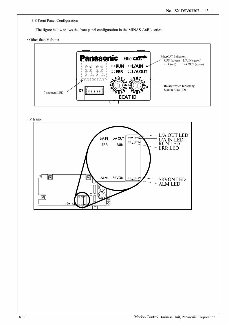
No. SX-DSV03307 - 43 -
R8.0 Motion Control Business Unit, Panasonic Corporation
3-8 Front Panel Configuration
The figure below shows the front panel configuration in the MINAS-A6BL series:
・Other than V frame
・V frame
EtherCAT Indicators RUN (green) L/A IN (green) EER (red) L/A OUT (green)
7 segment LED
Rotary switch for setting Station Alias (ID)
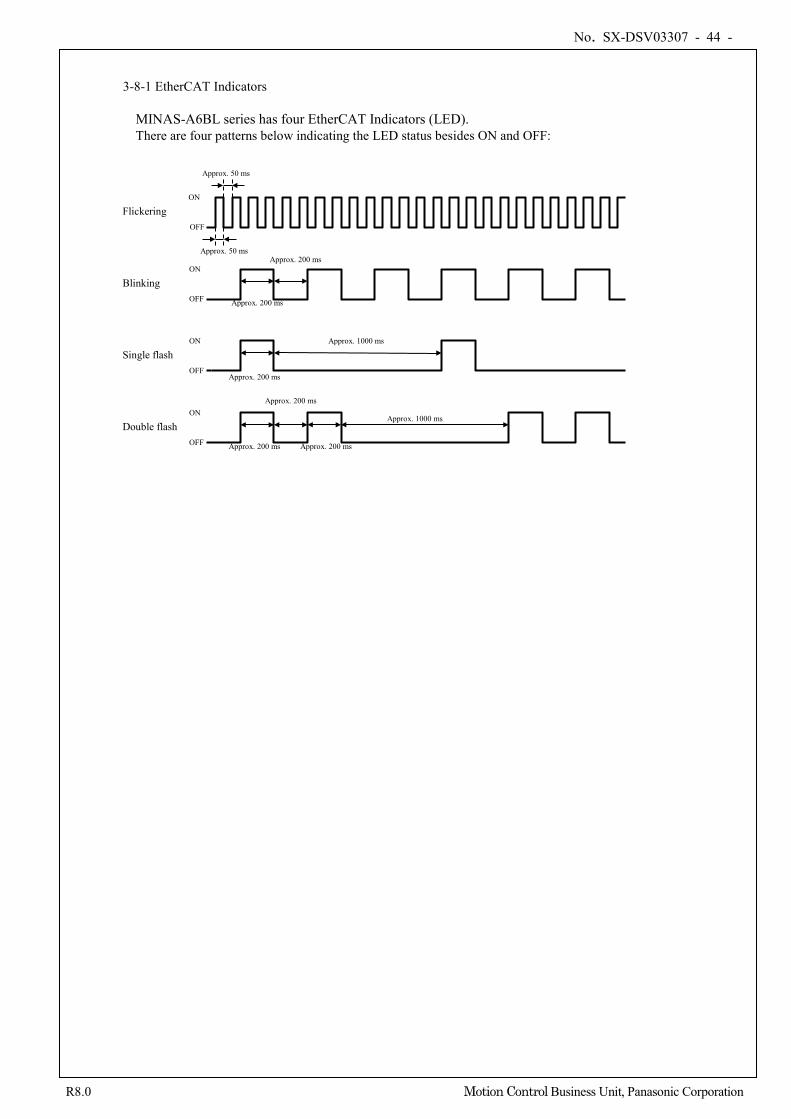
No. SX-DSV03307 - 44 -
R8.0 Motion Control Business Unit, Panasonic Corporation
3-8-1 EtherCAT Indicators MINAS-A6BL series has four EtherCAT Indicators (LED). There are four patterns below indicating the LED status besides ON and OFF:
Flickering
Blinking
Single flash
Double flash
Approx. 200 ms
Approx. 200 ms
Approx. 200 ms
Approx. 1000 ms
Approx. 1000 ms
Approx. 50 ms
Approx. 50 ms
ON
OFF
OFF
ON
OFF
ON
OFF
ON Approx. 200 ms
Approx. 200 ms Approx. 200 ms
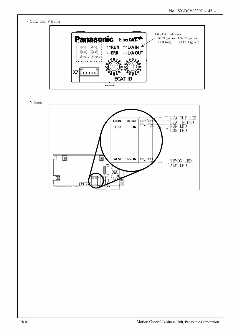
No. SX-DSV03307 - 45 -
R8.0 Motion Control Business Unit, Panasonic Corporation
・Other than V frame
・V frame
EtherCAT Indicators RUN (green) L/A IN (green) EER (red) L/A OUT (green)
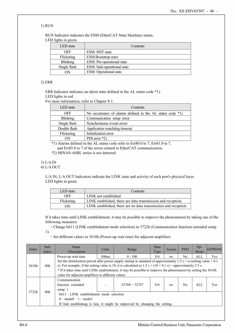
No. SX-DSV03307 - 46 -
R8.0 Motion Control Business Unit, Panasonic Corporation
1) RUN RUN Indicator indicates the ESM (EtherCAT State Machine) status. LED lights in green.
LED state Contents OFF ESM: INIT state
Flickering ESM:Bootstrap state Blinking ESM: Pre-operational state
Single flash ESM: Safe-operational state ON ESM: Operational state
2) ERR
ERR Indicator indicates an alarm state defined in the AL status code *1). LED lights in red. For more information, refer to Chapter 8-1.
LED state Contents OFF No occurrence of alarms defined in the AL status code *1)
Blinking Communication setup error Single flash Synchronous event error Double flash Application watchdog timeout Flickering Initialization error
ON PDI error *2) *1) Alarms defined in the AL status code refer to Err80.0 to 7, Err81.0 to 7,
and Err85.0 to 7 of the errors related to EtherCAT communication. *2) MINAS-A6BL series is not detected.
3) L/A IN 4) L/A OUT
L/A IN, L/A OUT Indicators indicate the LINK state and activity of each port's physical layer. LED lights in green.
LED state Contents OFF LINK not established
Flickering LINK established, there are data transmission and reception. ON LINK established, there are no data transmission and reception.
If it takes time until LINK establishment, it may be possible to improve the phenomenon by taking one of the following measures: ・Change bit11 (LINK establishment mode selection) in 3722h (Communication function extended setup 1). ・Set different values in 3618h (Power-up wait time) for adjacent amplifiers.
Index Sub- Index
Name / Description
Units Range Data Type
Access PDO Op-
Mode EEPROM
3618h 00h
Power-up wait time 100ms 0 - 100 I16 rw No ALL Yes Set the initialization period after power supply startup as standard of approximately 1.5 s + α (setting value × 0.1 s). For example, if the setting value is 10, it is calculated as 1.5 s + (10 × 0.1 s) = approximately 2.5 s. * If it takes time until LINK establishment, it may be possible to improve the phenomenon by setting the 3618h value for adjacent amplifiers to different values.
3722h 00h
Communication function extended
setup 1 - -32768 – 32767 I16 rw No ALL Yes
bit11:LINK establishment mode selection 0:mode0 1:mode1 If link establishing is late, it might be improved by changing the setting.
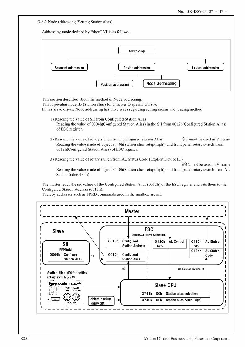
No. SX-DSV03307 - 47 -
R8.0 Motion Control Business Unit, Panasonic Corporation
3-8-2 Node addressing (Setting Station alias)
Addressing mode defined by EtherCAT is as follows.
This section describes about the method of Node addressing. This is peculiar node ID (Station alias) for a master to specify a slave. In this servo driver, Node addressing has three ways regarding setting means and reading method. 1) Reading the value of SII from Configured Station Alias
Reading the value of 0004h(Configured Station Alias) in the SII from 0012h(Configured Station Alias) of ESC register.
2) Reading the value of rotary switch from Configured Station Alias ※Cannot be used in V frame
Reading the value made of object 3740h(Station alias setup(high)) and front panel rotary switch from 0012h(Configured Station Alias) of ESC register.
3) Reading the value of rotary switch from AL Status Code (Explicit Device ID)
※Cannot be used in V frame Reading the value made of object 3740h(Station alias setup(high)) and front panel rotary switch from AL Status Code(0134h).
The master reads the set values of the Configured Station Alias (0012h) of the ESC register and sets them to the Configured Station Address (0010h). Thereby addresses such as FPRD commands used in the mailbox are set.
Position addressing
Device addressing Segment addressing Logical addressing
Addressing
Node addressing
ESC (EtherCAT Slave Controller)
SII (EEPROM)
Slave CPU
object backup
(EEPROM)
Station Alias (ID)for setting
rotary switch(RSW)
0004h Configured
Station Alias
0012h Configured
Station Alias
3741h 00h Station alias selection
3740h 00h Station alias setup(high)
0120h
bit5
AL Control
0130h
bit5
AL Status
0134h AL Status
Code
1)
2) 3) Explicit Device ID
0010h Configured
Station Address
Slave
Master
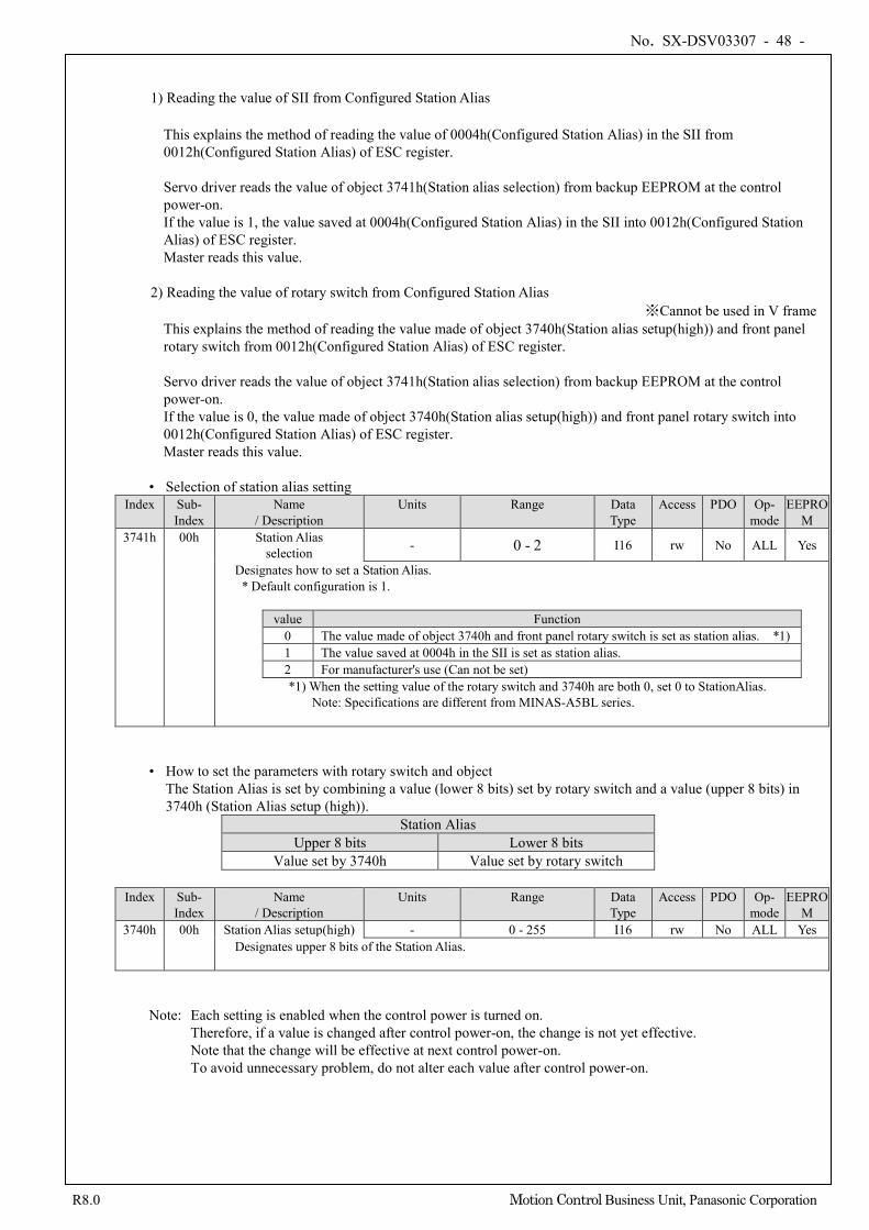
No. SX-DSV03307 - 48 -
R8.0 Motion Control Business Unit, Panasonic Corporation
1) Reading the value of SII from Configured Station Alias
This explains the method of reading the value of 0004h(Configured Station Alias) in the SII from 0012h(Configured Station Alias) of ESC register. Servo driver reads the value of object 3741h(Station alias selection) from backup EEPROM at the control power-on. If the value is 1, the value saved at 0004h(Configured Station Alias) in the SII into 0012h(Configured Station Alias) of ESC register. Master reads this value.
2) Reading the value of rotary switch from Configured Station Alias ※Cannot be used in V frame
This explains the method of reading the value made of object 3740h(Station alias setup(high)) and front panel rotary switch from 0012h(Configured Station Alias) of ESC register. Servo driver reads the value of object 3741h(Station alias selection) from backup EEPROM at the control power-on. If the value is 0, the value made of object 3740h(Station alias setup(high)) and front panel rotary switch into 0012h(Configured Station Alias) of ESC register. Master reads this value.
• Selection of station alias setting
Index Sub- Index
Name / Description
Units Range Data Type
Access PDO Op- mode
EEPROM
3741h 00h Station Alias selection - 0 - 2 I16 rw No ALL Yes
Designates how to set a Station Alias. * Default configuration is 1.
value Function 0 The value made of object 3740h and front panel rotary switch is set as station alias. *1) 1 The value saved at 0004h in the SII is set as station alias. 2 For manufacturer's use (Can not be set) *1) When the setting value of the rotary switch and 3740h are both 0, set 0 to StationAlias.
Note: Specifications are different from MINAS-A5BL series.
• How to set the parameters with rotary switch and object The Station Alias is set by combining a value (lower 8 bits) set by rotary switch and a value (upper 8 bits) in 3740h (Station Alias setup (high)).
Station Alias Upper 8 bits Lower 8 bits
Value set by 3740h Value set by rotary switch
Index Sub- Index
Name / Description
Units Range Data Type
Access PDO Op- mode
EEPROM
3740h 00h Station Alias setup(high) - 0 - 255 I16 rw No ALL Yes Designates upper 8 bits of the Station Alias.
Note: Each setting is enabled when the control power is turned on.
Therefore, if a value is changed after control power-on, the change is not yet effective. Note that the change will be effective at next control power-on. To avoid unnecessary problem, do not alter each value after control power-on.
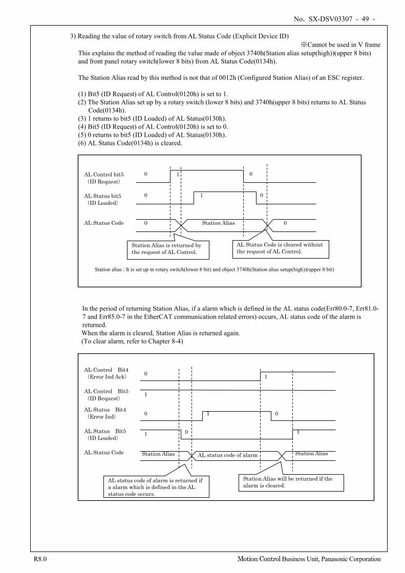
No. SX-DSV03307 - 49 -
R8.0 Motion Control Business Unit, Panasonic Corporation
3) Reading the value of rotary switch from AL Status Code (Explicit Device ID)
※Cannot be used in V frame This explains the method of reading the value made of object 3740h(Station alias setup(high))(upper 8 bits) and front panel rotary switch(lower 8 bits) from AL Status Code(0134h). The Station Alias read by this method is not that of 0012h (Configured Station Alias) of an ESC register. (1) Bit5 (ID Request) of AL Control(0120h) is set to 1. (2) The Station Alias set up by a rotary switch (lower 8 bits) and 3740h(upper 8 bits) returns to AL Status
Code(0134h). (3) 1 returns to bit5 (ID Loaded) of AL Status(0130h). (4) Bit5 (ID Request) of AL Control(0120h) is set to 0. (5) 0 returns to bit5 (ID Loaded) of AL Status(0130h). (6) AL Status Code(0134h) is cleared.
In the period of returning Station Alias, if a alarm which is defined in the AL status code(Err80.0-7, Err81.0-7 and Err85.0-7 in the EtherCAT communication related errors) occurs, AL status code of the alarm is returned.
When the alarm is cleared, Station Alias is returned again. (To clear alarm, refer to Chapter 8-4)
AL Control bit5 (ID Request)
AL Status bit5 (ID Loaded)
AL Status Code 0 Station Alias 0
0
0
0
0
1
1
Station Alias is returned by the request of AL Control.
AL Status Code is cleared without the request of AL Control.
Station alias : It is set up in rotary switch(lower 8 bit) and object 3740h(Station alias setup(high))(upper 8 bit)
Station Alias Station Alias AL status code of alarm
0
1
0
1
1
1
0
0
1
AL Control Bit4 (Error Ind Ack)
AL Control Bit5 (ID Request)
AL Status Bit4 (Error Ind)
AL Status Bit5 (ID Loaded)
AL Status Code
AL status code of alarm is returned if a alarm which is defined in the AL status code occurs.
Station Alias will be returned if the alarm is cleared.
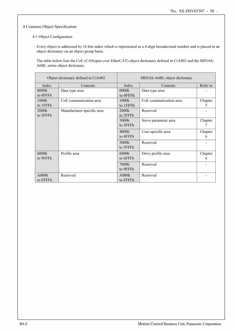
No. SX-DSV03307 - 50 -
R8.0 Motion Control Business Unit, Panasonic Corporation
4 Common Object Specification
4-1 Object Configuration
Every object is addressed by 16 bits index which is represented as a 4-digit hexadecimal number and is placed in an object dictionary on an object group basis. The table below lists the CoE (CANopen over EtherCAT) object dictionary defined in CiA402 and the MINAS-A6BL series object dictionary.
Object dictionary defined in CiA402 MINAS-A6BL object dictionary
Index Contents Index Contents Refer to 0000h to 0FFFh
Data type area 0000h to 0FFFh
Data type area -
1000h to 1FFFh
CoE communication area 1000h to 1FFFh
CoE communication area Chapter 5
2000h to 5FFFh
Manufacturer-specific area 2000h to 2FFFh
Reserved -
3000h to 3FFFh
Servo parameter area Chapter 7
4000h to 4FFFh
User-specific area Chapter 6
5000h to 5FFFh
Reserved -
6000h to 9FFFh
Profile area 6000h to 6FFFh
Drive profile area Chapter 6
7000h to 9FFFh
Reserved -
A000h to FFFFh
Reserved A000h to FFFFh
Reserved -
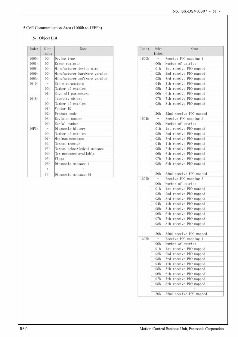
No. SX-DSV03307 - 51 -
R8.0 Motion Control Business Unit, Panasonic Corporation
5 CoE Communication Area (1000h to 1FFFh)
5-1 Object List
Index Sub-
Index
Name
1000h 00h Device type
1001h 00h Error register
1008h 00h Manufacturer device name
1009h 00h Manufacturer hardware version
100Ah 00h Manufacturer software version
1010h - Store parameters
00h Number of entries
01h Save all parameters
1018h - Identity object
00h Number of entries
01h Vendor ID
02h Product code
03h Revision number
04h Serial number
10F3h - Diagnosis history
00h Number of entries
01h Maximum messages
02h Newest message
03h Newest acknowledged message
04h New messages available
05h Flags
06h Diagnosis message 1
: :
13h Diagnosis message 14
Index Sub-
Index
Name
1600h - Receive PDO mapping 1
00h Number of entries
01h 1st receive PDO mapped
02h 2nd receive PDO mapped
03h 3rd receive PDO mapped
04h 4th receive PDO mapped
05h 5th receive PDO mapped
06h 6th receive PDO mapped
07h 7th receive PDO mapped
08h 8th receive PDO mapped
: :
20h 32nd receive PDO mapped
1601h - Receive PDO mapping 2
00h Number of entries
01h 1st receive PDO mapped
02h 2nd receive PDO mapped
03h 3rd receive PDO mapped
04h 4th receive PDO mapped
05h 5th receive PDO mapped
06h 6th receive PDO mapped
07h 7th receive PDO mapped
08h 8th receive PDO mapped
: :
20h 32nd receive PDO mapped
1602h - Receive PDO mapping 3
00h Number of entries
01h 1st receive PDO mapped
02h 2nd receive PDO mapped
03h 3rd receive PDO mapped
04h 4th receive PDO mapped
05h 5th receive PDO mapped
06h 6th receive PDO mapped
07h 7th receive PDO mapped
08h 8th receive PDO mapped
: :
20h 32nd receive PDO mapped
1603h - Receive PDO mapping 4
00h Number of entries
01h 1st receive PDO mapped
02h 2nd receive PDO mapped
03h 3rd receive PDO mapped
04h 4th receive PDO mapped
05h 5th receive PDO mapped
06h 6th receive PDO mapped
07h 7th receive PDO mapped
08h 8th receive PDO mapped
: :
20h 32nd receive PDO mapped
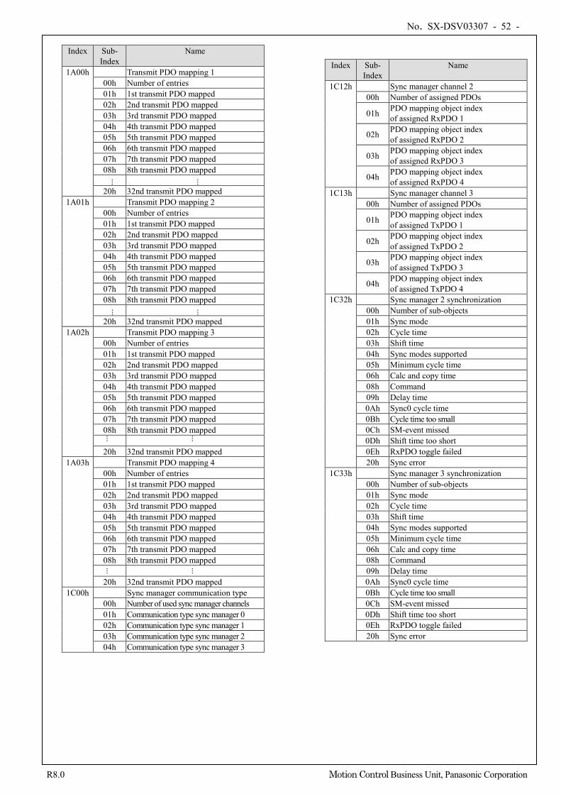
No. SX-DSV03307 - 52 -
R8.0 Motion Control Business Unit, Panasonic Corporation
Index Sub-
Index Name
1A00h Transmit PDO mapping 1 00h Number of entries 01h 1st transmit PDO mapped 02h 2nd transmit PDO mapped 03h 3rd transmit PDO mapped 04h 4th transmit PDO mapped 05h 5th transmit PDO mapped 06h 6th transmit PDO mapped 07h 7th transmit PDO mapped 08h 8th transmit PDO mapped
...
...
20h 32nd transmit PDO mapped 1A01h Transmit PDO mapping 2
00h Number of entries 01h 1st transmit PDO mapped 02h 2nd transmit PDO mapped 03h 3rd transmit PDO mapped 04h 4th transmit PDO mapped 05h 5th transmit PDO mapped 06h 6th transmit PDO mapped 07h 7th transmit PDO mapped 08h 8th transmit PDO mapped
...
...
20h 32nd transmit PDO mapped 1A02h Transmit PDO mapping 3
00h Number of entries 01h 1st transmit PDO mapped 02h 2nd transmit PDO mapped 03h 3rd transmit PDO mapped 04h 4th transmit PDO mapped 05h 5th transmit PDO mapped 06h 6th transmit PDO mapped 07h 7th transmit PDO mapped 08h 8th transmit PDO mapped
...
...
20h 32nd transmit PDO mapped 1A03h Transmit PDO mapping 4
00h Number of entries 01h 1st transmit PDO mapped 02h 2nd transmit PDO mapped 03h 3rd transmit PDO mapped 04h 4th transmit PDO mapped 05h 5th transmit PDO mapped 06h 6th transmit PDO mapped 07h 7th transmit PDO mapped 08h 8th transmit PDO mapped
...
...
20h 32nd transmit PDO mapped 1C00h Sync manager communication type
00h Number of used sync manager channels 01h Communication type sync manager 0 02h Communication type sync manager 1 03h Communication type sync manager 2 04h Communication type sync manager 3
Index Sub- Index
Name
1C12h Sync manager channel 2 00h Number of assigned PDOs
01h PDO mapping object index of assigned RxPDO 1
02h PDO mapping object index of assigned RxPDO 2
03h PDO mapping object index of assigned RxPDO 3
04h PDO mapping object index of assigned RxPDO 4
1C13h Sync manager channel 3 00h Number of assigned PDOs
01h PDO mapping object index of assigned TxPDO 1
02h PDO mapping object index of assigned TxPDO 2
03h PDO mapping object index of assigned TxPDO 3
04h PDO mapping object index of assigned TxPDO 4
1C32h Sync manager 2 synchronization 00h Number of sub-objects 01h Sync mode 02h Cycle time 03h Shift time 04h Sync modes supported 05h Minimum cycle time 06h Calc and copy time 08h Command 09h Delay time 0Ah Sync0 cycle time 0Bh Cycle time too small 0Ch SM-event missed 0Dh Shift time too short 0Eh RxPDO toggle failed 20h Sync error 1C33h Sync manager 3 synchronization
00h Number of sub-objects 01h Sync mode 02h Cycle time 03h Shift time 04h Sync modes supported 05h Minimum cycle time 06h Calc and copy time 08h Command 09h Delay time 0Ah Sync0 cycle time 0Bh Cycle time too small 0Ch SM-event missed 0Dh Shift time too short 0Eh RxPDO toggle failed 20h Sync error
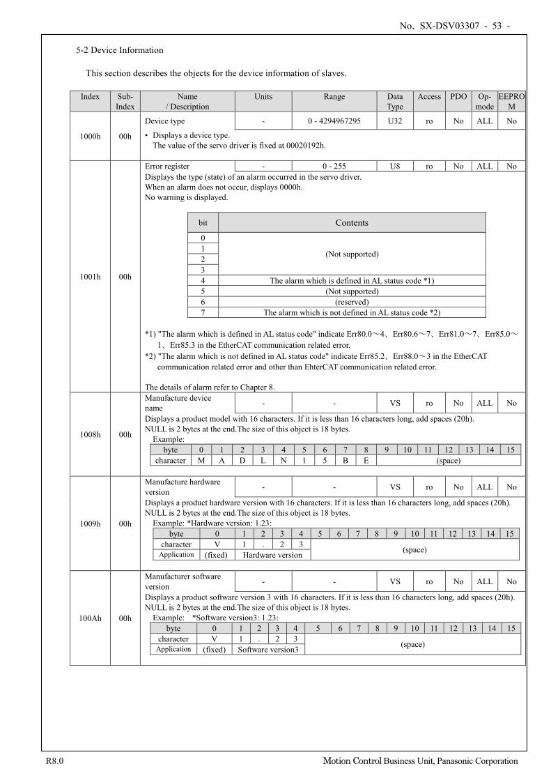
No. SX-DSV03307 - 53 -
R8.0 Motion Control Business Unit, Panasonic Corporation
5-2 Device Information
This section describes the objects for the device information of slaves.
Index Sub-
Index Name
/ Description Units Range Data
Type Access PDO Op-
mode EEPRO
M
1000h 00h
Device type - 0 - 4294967295 U32 ro No ALL No
• Displays a device type. The value of the servo driver is fixed at 00020192h.
1001h 00h
Error register - 0 - 255 U8 ro No ALL No Displays the type (state) of an alarm occurred in the servo driver. When an alarm does not occur, displays 0000h. No warning is displayed.
bit Contents
0
(Not supported) 1 2 3 4 The alarm which is defined in AL status code *1) 5 (Not supported) 6 (reserved) 7 The alarm which is not defined in AL status code *2)
*1) "The alarm which is defined in AL status code" indicate Err80.0~4、Err80.6~7、Err81.0~7、Err85.0~
1、Err85.3 in the EtherCAT communication related error. *2) "The alarm which is not defined in AL status code" indicate Err85.2、Err88.0~3 in the EtherCAT
communication related error and other than EhterCAT communication related error. The details of alarm refer to Chapter 8.
1008h 00h
Manufacture device name - - VS ro No ALL No
Displays a product model with 16 characters. If it is less than 16 characters long, add spaces (20h). NULL is 2 bytes at the end.The size of this object is 18 bytes.
Example: byte 0 1 2 3 4 5 6 7 8 9 10 11 12 13 14 15
character M A D L N 1 5 B E (space)
1009h 00h
Manufacture hardware version - - VS ro No ALL No
Displays a product hardware version with 16 characters. If it is less than 16 characters long, add spaces (20h). NULL is 2 bytes at the end.The size of this object is 18 bytes.
Example: *Hardware version: 1.23: byte 0 1 2 3 4 5 6 7 8 9 10 11 12 13 14 15
character V 1 . 2 3 (space) Application (fixed) Hardware version
100Ah 00h
Manufacturer software version - - VS ro No ALL No
Displays a product software version 3 with 16 characters. If it is less than 16 characters long, add spaces (20h). NULL is 2 bytes at the end.The size of this object is 18 bytes.
Example: *Software version3: 1.23: byte 0 1 2 3 4 5 6 7 8 9 10 11 12 13 14 15
character V 1 . 2 3 (space) Application (fixed) Software version3
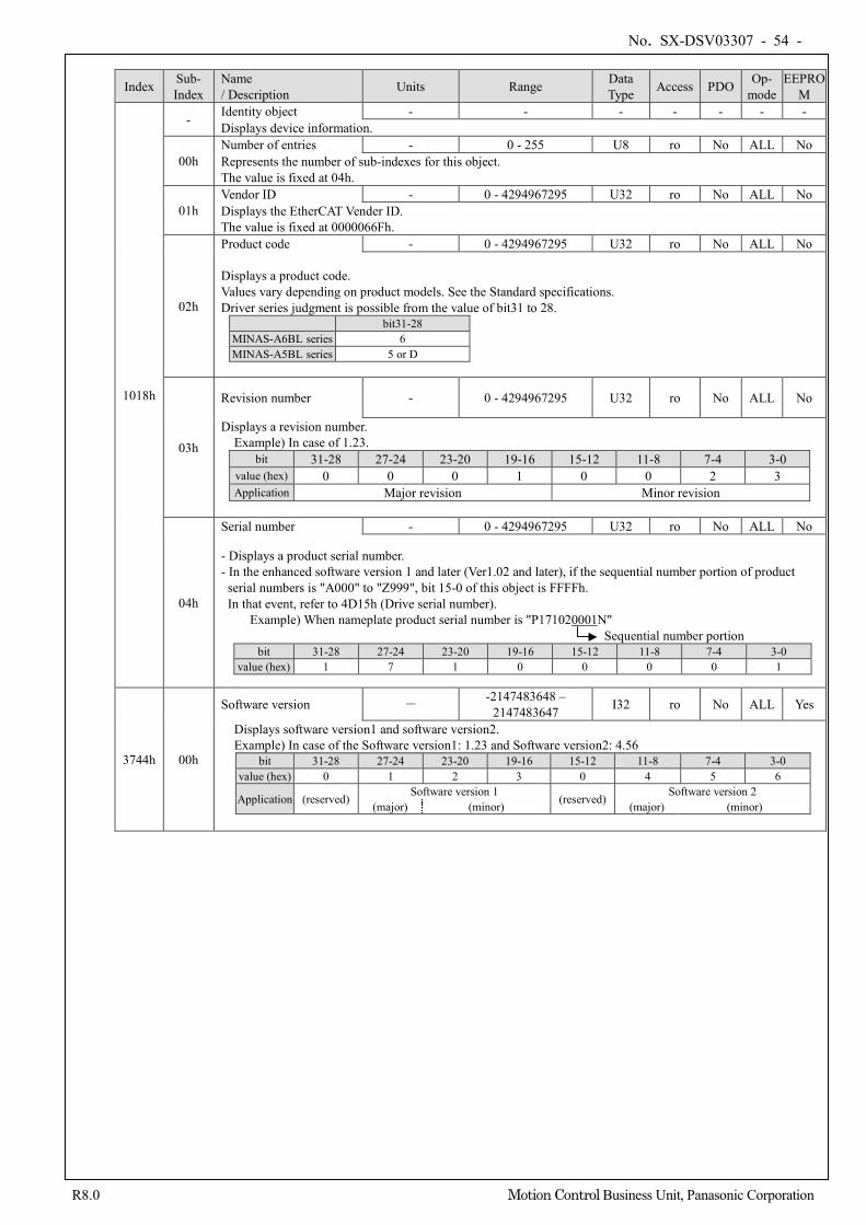
No. SX-DSV03307 - 54 -
R8.0 Motion Control Business Unit, Panasonic Corporation
Index Sub- Index
Name / Description Units Range Data
Type Access PDO Op- mode
EEPROM
1018h
- Identity object - - - - - - - Displays device information.
00h Number of entries - 0 - 255 U8 ro No ALL No Represents the number of sub-indexes for this object. The value is fixed at 04h.
01h Vendor ID - 0 - 4294967295 U32 ro No ALL No Displays the EtherCAT Vender ID. The value is fixed at 0000066Fh.
02h
Product code - 0 - 4294967295 U32 ro No ALL No
Displays a product code. Values vary depending on product models. See the Standard specifications. Driver series judgment is possible from the value of bit31 to 28.
bit31-28 MINAS-A6BL series 6 MINAS-A5BL series 5 or D
03h
Revision number - 0 - 4294967295 U32 ro No ALL No
Displays a revision number. Example) In case of 1.23.
bit 31-28 27-24 23-20 19-16 15-12 11-8 7-4 3-0 value (hex) 0 0 0 1 0 0 2 3 Application Major revision Minor revision
04h
Serial number - 0 - 4294967295 U32 ro No ALL No
- Displays a product serial number. - In the enhanced software version 1 and later (Ver1.02 and later), if the sequential number portion of product
serial numbers is "A000" to "Z999", bit 15-0 of this object is FFFFh. In that event, refer to 4D15h (Drive serial number).
Example) When nameplate product serial number is "P171020001N" Sequential number portion
bit 31-28 27-24 23-20 19-16 15-12 11-8 7-4 3-0 value (hex) 1 7 1 0 0 0 0 1
3744h 00h
Software version - -2147483648 – 2147483647 I32 ro No ALL Yes
Displays software version1 and software version2. Example) In case of the Software version1: 1.23 and Software version2: 4.56
bit 31-28 27-24 23-20 19-16 15-12 11-8 7-4 3-0 value (hex) 0 1 2 3 0 4 5 6
Application (reserved) Software version 1 (reserved) Software version 2 (major) (minor) (major) (minor)
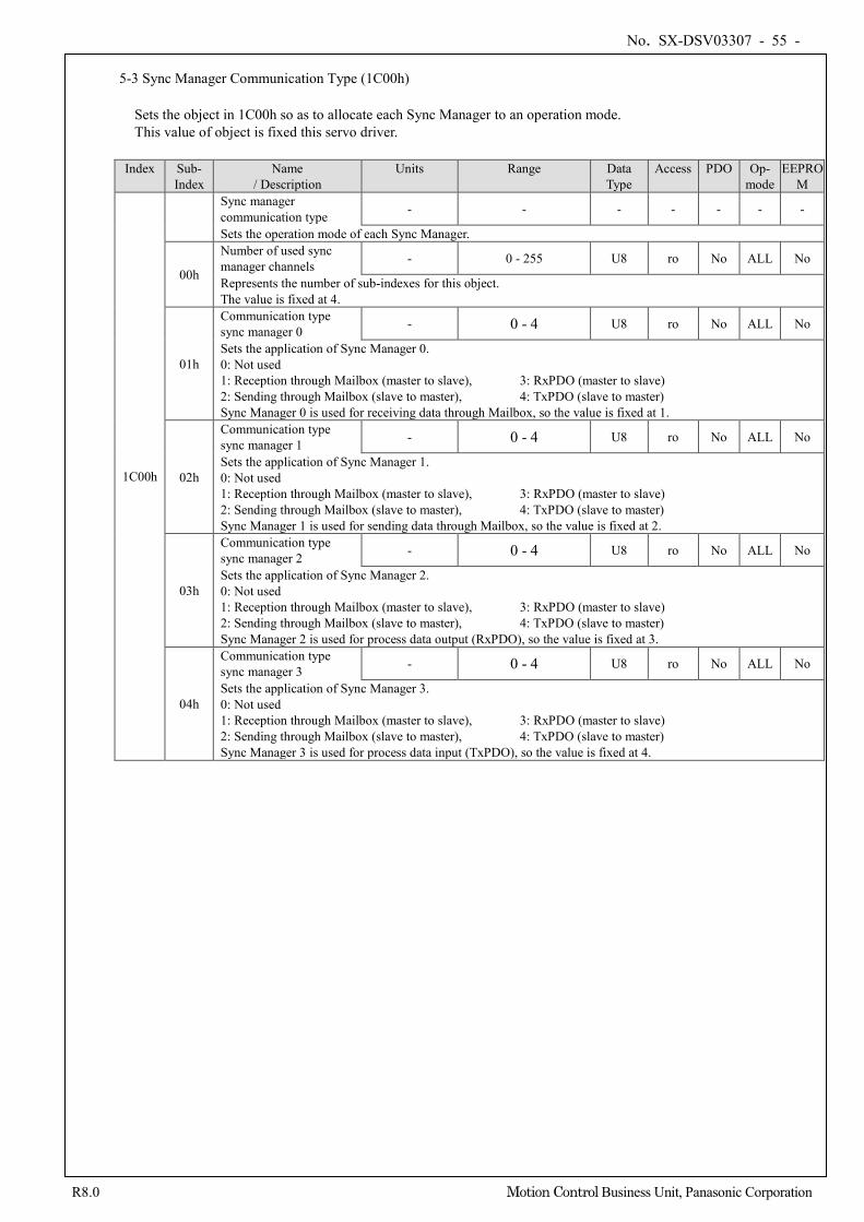
No. SX-DSV03307 - 55 -
R8.0 Motion Control Business Unit, Panasonic Corporation
5-3 Sync Manager Communication Type (1C00h)
Sets the object in 1C00h so as to allocate each Sync Manager to an operation mode. This value of object is fixed this servo driver.
Index Sub-
Index Name
/ Description Units Range Data
Type Access PDO Op-
mode EEPRO
M
1C00h
Sync manager communication type - - - - - - -
Sets the operation mode of each Sync Manager.
00h
Number of used sync manager channels - 0 - 255 U8 ro No ALL No
Represents the number of sub-indexes for this object. The value is fixed at 4.
01h
Communication type sync manager 0 - 0 - 4 U8 ro No ALL No
Sets the application of Sync Manager 0. 0: Not used 1: Reception through Mailbox (master to slave), 3: RxPDO (master to slave) 2: Sending through Mailbox (slave to master), 4: TxPDO (slave to master) Sync Manager 0 is used for receiving data through Mailbox, so the value is fixed at 1.
02h
Communication type sync manager 1 - 0 - 4 U8 ro No ALL No
Sets the application of Sync Manager 1. 0: Not used 1: Reception through Mailbox (master to slave), 3: RxPDO (master to slave) 2: Sending through Mailbox (slave to master), 4: TxPDO (slave to master) Sync Manager 1 is used for sending data through Mailbox, so the value is fixed at 2.
03h
Communication type sync manager 2 - 0 - 4 U8 ro No ALL No
Sets the application of Sync Manager 2. 0: Not used 1: Reception through Mailbox (master to slave), 3: RxPDO (master to slave) 2: Sending through Mailbox (slave to master), 4: TxPDO (slave to master) Sync Manager 2 is used for process data output (RxPDO), so the value is fixed at 3.
04h
Communication type sync manager 3 - 0 - 4 U8 ro No ALL No
Sets the application of Sync Manager 3. 0: Not used 1: Reception through Mailbox (master to slave), 3: RxPDO (master to slave) 2: Sending through Mailbox (slave to master), 4: TxPDO (slave to master) Sync Manager 3 is used for process data input (TxPDO), so the value is fixed at 4.
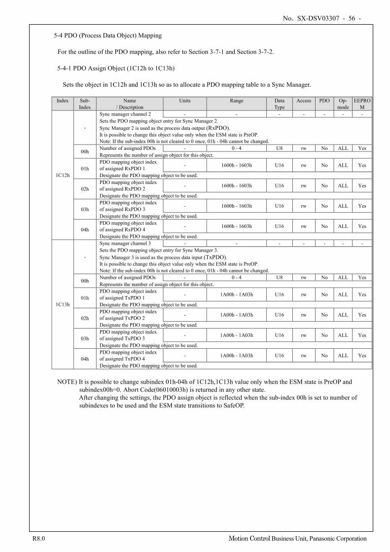
No. SX-DSV03307 - 56 -
R8.0 Motion Control Business Unit, Panasonic Corporation
5-4 PDO (Process Data Object) Mapping
For the outline of the PDO mapping, also refer to Section 3-7-1 and Section 3-7-2. 5-4-1 PDO Assign Object (1C12h to 1C13h)
Sets the object in 1C12h and 1C13h so as to allocate a PDO mapping table to a Sync Manager.
Index Sub-
Index Name
/ Description Units Range Data
Type Access PDO Op-
mode EEPRO
M
1C12h
-
Sync manager channel 2 - - - - - - - Sets the PDO mapping object entry for Sync Manager 2. Sync Manager 2 is used as the process data output (RxPDO). It is possible to change this object value only when the ESM state is PreOP. Note: If the sub-index 00h is not cleared to 0 once, 01h - 04h cannot be changed.
00h Number of assigned PDOs - 0 - 4 U8 rw No ALL Yes Represents the number of assign object for this object.
01h PDO mapping object index of assigned RxPDO 1 - 1600h - 1603h U16 rw No ALL Yes
Designate the PDO mapping object to be used.
02h PDO mapping object index of assigned RxPDO 2 - 1600h - 1603h U16 rw No ALL Yes
Designate the PDO mapping object to be used.
03h PDO mapping object index of assigned RxPDO 3 - 1600h - 1603h U16 rw No ALL Yes
Designate the PDO mapping object to be used.
04h PDO mapping object index of assigned RxPDO 4 - 1600h - 1603h U16 rw No ALL Yes
Designate the PDO mapping object to be used.
1C13h
-
Sync manager channel 3 - - - - - - - Sets the PDO mapping object entry for Sync Manager 3. Sync Manager 3 is used as the process data input (TxPDO). It is possible to change this object value only when the ESM state is PreOP. Note: If the sub-index 00h is not cleared to 0 once, 01h - 04h cannot be changed.
00h Number of assigned PDOs - 0 - 4 U8 rw No ALL Yes Represents the number of assign object for this object.
01h PDO mapping object index of assigned TxPDO 1 - 1A00h - 1A03h U16 rw No ALL Yes
Designate the PDO mapping object to be used.
02h PDO mapping object index of assigned TxPDO 2 - 1A00h - 1A03h U16 rw No ALL Yes
Designate the PDO mapping object to be used.
03h PDO mapping object index of assigned TxPDO 3 - 1A00h - 1A03h U16 rw No ALL Yes
Designate the PDO mapping object to be used.
04h PDO mapping object index of assigned TxPDO 4 - 1A00h - 1A03h U16 rw No ALL Yes
Designate the PDO mapping object to be used.
NOTE) It is possible to change subindex 01h-04h of 1C12h,1C13h value only when the ESM state is PreOP and subindex00h=0. Abort Code(06010003h) is returned in any other state. After changing the settings, the PDO assign object is reflected when the sub-index 00h is set to number of subindexes to be used and the ESM state transitions to SafeOP.
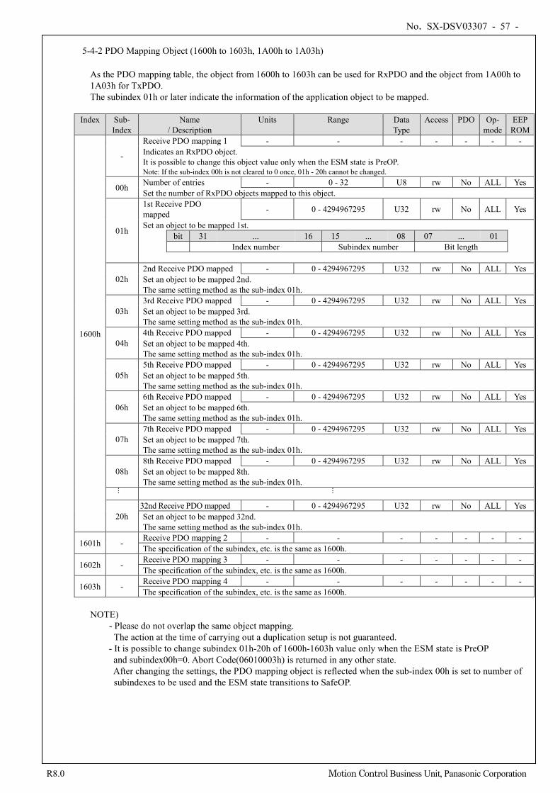
No. SX-DSV03307 - 57 -
R8.0 Motion Control Business Unit, Panasonic Corporation
5-4-2 PDO Mapping Object (1600h to 1603h, 1A00h to 1A03h)
As the PDO mapping table, the object from 1600h to 1603h can be used for RxPDO and the object from 1A00h to 1A03h for TxPDO. The subindex 01h or later indicate the information of the application object to be mapped.
Index Sub-
Index Name
/ Description Units Range Data
Type Access PDO Op-
mode EEP
ROM
1600h
-
Receive PDO mapping 1 - - - - - - - Indicates an RxPDO object. It is possible to change this object value only when the ESM state is PreOP. Note: If the sub-index 00h is not cleared to 0 once, 01h - 20h cannot be changed.
00h Number of entries - 0 - 32 U8 rw No ALL Yes Set the number of RxPDO objects mapped to this object.
01h
1st Receive PDO mapped - 0 - 4294967295 U32 rw No ALL Yes
Set an object to be mapped 1st. bit 31 ... 16 15 ... 08 07 ... 01
Index number Subindex number Bit length
02h 2nd Receive PDO mapped - 0 - 4294967295 U32 rw No ALL Yes Set an object to be mapped 2nd. The same setting method as the sub-index 01h.
03h 3rd Receive PDO mapped - 0 - 4294967295 U32 rw No ALL Yes Set an object to be mapped 3rd. The same setting method as the sub-index 01h.
04h 4th Receive PDO mapped - 0 - 4294967295 U32 rw No ALL Yes Set an object to be mapped 4th. The same setting method as the sub-index 01h.
05h 5th Receive PDO mapped - 0 - 4294967295 U32 rw No ALL Yes Set an object to be mapped 5th. The same setting method as the sub-index 01h.
06h 6th Receive PDO mapped - 0 - 4294967295 U32 rw No ALL Yes Set an object to be mapped 6th. The same setting method as the sub-index 01h.
07h 7th Receive PDO mapped - 0 - 4294967295 U32 rw No ALL Yes Set an object to be mapped 7th. The same setting method as the sub-index 01h.
08h 8th Receive PDO mapped - 0 - 4294967295 U32 rw No ALL Yes Set an object to be mapped 8th. The same setting method as the sub-index 01h. ...
...
20h 32nd Receive PDO mapped - 0 - 4294967295 U32 rw No ALL Yes Set an object to be mapped 32nd. The same setting method as the sub-index 01h.
1601h - Receive PDO mapping 2 - - - - - - - The specification of the subindex, etc. is the same as 1600h.
1602h - Receive PDO mapping 3 - - - - - - - The specification of the subindex, etc. is the same as 1600h.
1603h - Receive PDO mapping 4 - - - - - - - The specification of the subindex, etc. is the same as 1600h.
NOTE)
- Please do not overlap the same object mapping. The action at the time of carrying out a duplication setup is not guaranteed.
- It is possible to change subindex 01h-20h of 1600h-1603h value only when the ESM state is PreOP and subindex00h=0. Abort Code(06010003h) is returned in any other state. After changing the settings, the PDO mapping object is reflected when the sub-index 00h is set to number of subindexes to be used and the ESM state transitions to SafeOP.
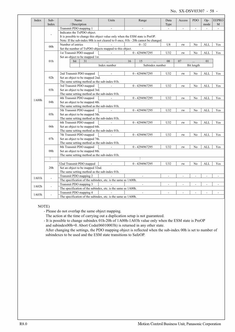
No. SX-DSV03307 - 58 -
R8.0 Motion Control Business Unit, Panasonic Corporation
Index Sub- Index
Name / Description
Units Range Data Type
Access PDO Op- mode
EEPROM
1A00h
-
Transmit PDO mapping 1 - - - - - - - Indicates the TxPDO object. It is possible to change this object value only when the ESM state is PreOP. Note: If the sub-index 00h is not cleared to 0 once, 01h - 20h cannot be changed.
00h Number of entries - 0 - 32 U8 rw No ALL Yes Set the number of TxPDO objects mapped to this object.
01h
1st Transmit PDO mapped - 0 - 4294967295 U32 rw No ALL Yes Set an object to be mapped 1st.
bit 31 ... 16 15 ... 08 07 ... 01 Index number Subindex number Bit length
02h 2nd Transmit PDO mapped - 0 - 4294967295 U32 rw No ALL Yes Set an object to be mapped 2nd. The same setting method as the sub-index 01h.
03h 3rd Transmit PDO mapped - 0 - 4294967295 U32 rw No ALL Yes Set an object to be mapped 3rd. The same setting method as the sub-index 01h.
04h 4th Transmit PDO mapped - 0 - 4294967295 U32 rw No ALL Yes Set an object to be mapped 4th. The same setting method as the sub-index 01h.
05h 5th Transmit PDO mapped - 0 - 4294967295 U32 rw No ALL Yes Set an object to be mapped 5th. The same setting method as the sub-index 01h.
06h 6th Transmit PDO mapped - 0 - 4294967295 U32 rw No ALL Yes Set an object to be mapped 6th. The same setting method as the sub-index 01h.
07h 7th Transmit PDO mapped - 0 - 4294967295 U32 rw No ALL Yes Set an object to be mapped 7th. The same setting method as the sub-index 01h.
08h 8th Transmit PDO mapped - 0 - 4294967295 U32 rw No ALL Yes Set an object to be mapped 8th. The same setting method as the sub-index 01h. ...
...
20h 32nd Transmit PDO mapped - 0 - 4294967295 U32 rw No ALL Yes Set an object to be mapped 32nd. The same setting method as the sub-index 01h.
1A01h - Transmit PDO mapping 2 - - - - - - - The specification of the subindex, etc. is the same as 1A00h.
1A02h - Transmit PDO mapping 3 - - - - - - - The specification of the subindex, etc. is the same as 1A00h.
1A03h - Transmit PDO mapping 4 - - - - - - - The specification of the subindex, etc. is the same as 1A00h.
NOTE)
- Please do not overlap the same object mapping. The action at the time of carrying out a duplication setup is not guaranteed.
- It is possible to change subindex 01h-20h of 1A00h-1A03h value only when the ESM state is PreOP and subindex00h=0. Abort Code(06010003h) is returned in any other state. After changing the settings, the PDO mapping object is reflected when the sub-index 00h is set to number of subindexes to be used and the ESM state transitions to SafeOP.
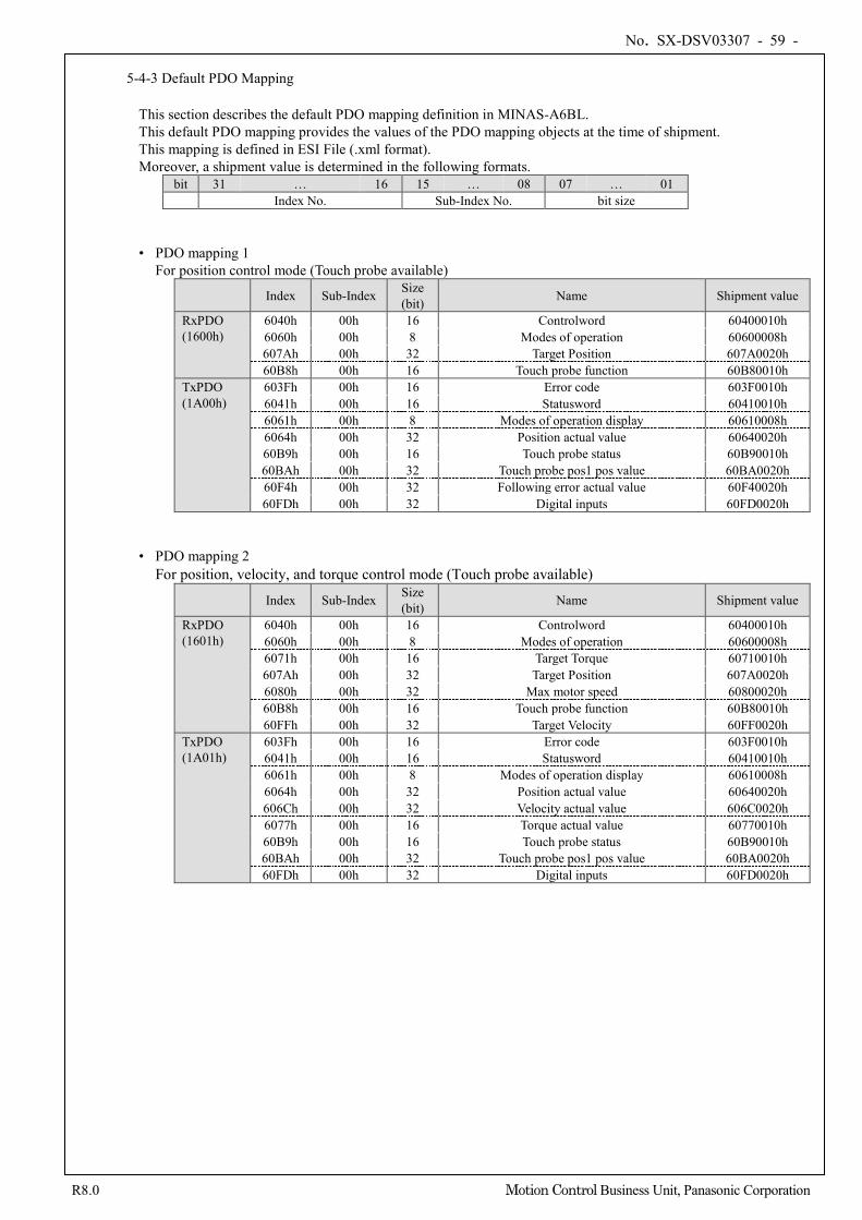
No. SX-DSV03307 - 59 -
R8.0 Motion Control Business Unit, Panasonic Corporation
5-4-3 Default PDO Mapping
This section describes the default PDO mapping definition in MINAS-A6BL. This default PDO mapping provides the values of the PDO mapping objects at the time of shipment. This mapping is defined in ESI File (.xml format). Moreover, a shipment value is determined in the following formats.
bit 31 … 16 15 … 08 07 … 01 Index No. Sub-Index No. bit size
• PDO mapping 1
For position control mode (Touch probe available) Index Sub-Index Size
(bit) Name Shipment value
RxPDO (1600h)
6040h 00h 16 Controlword 60400010h 6060h 00h 8 Modes of operation 60600008h 607Ah 00h 32 Target Position 607A0020h 60B8h 00h 16 Touch probe function 60B80010h
TxPDO (1A00h)
603Fh 00h 16 Error code 603F0010h 6041h 00h 16 Statusword 60410010h 6061h 00h 8 Modes of operation display 60610008h 6064h 00h 32 Position actual value 60640020h 60B9h 00h 16 Touch probe status 60B90010h 60BAh 00h 32 Touch probe pos1 pos value 60BA0020h 60F4h 00h 32 Following error actual value 60F40020h 60FDh 00h 32 Digital inputs 60FD0020h
• PDO mapping 2 For position, velocity, and torque control mode (Touch probe available)
Index Sub-Index Size (bit) Name Shipment value
RxPDO (1601h)
6040h 00h 16 Controlword 60400010h 6060h 00h 8 Modes of operation 60600008h 6071h 00h 16 Target Torque 60710010h 607Ah 00h 32 Target Position 607A0020h 6080h 00h 32 Max motor speed 60800020h 60B8h 00h 16 Touch probe function 60B80010h 60FFh 00h 32 Target Velocity 60FF0020h
TxPDO (1A01h)
603Fh 00h 16 Error code 603F0010h 6041h 00h 16 Statusword 60410010h 6061h 00h 8 Modes of operation display 60610008h 6064h 00h 32 Position actual value 60640020h 606Ch 00h 32 Velocity actual value 606C0020h 6077h 00h 16 Torque actual value 60770010h 60B9h 00h 16 Touch probe status 60B90010h 60BAh 00h 32 Touch probe pos1 pos value 60BA0020h 60FDh 00h 32 Digital inputs 60FD0020h
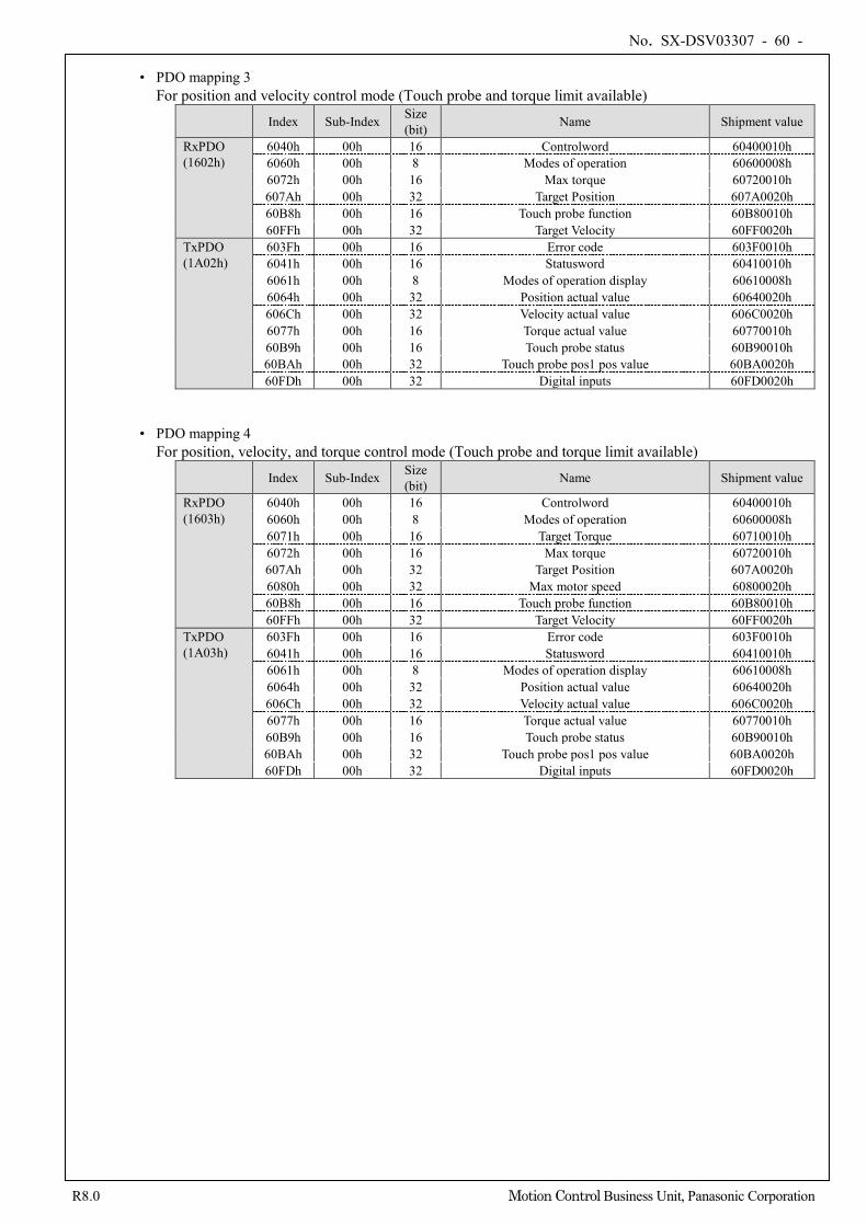
No. SX-DSV03307 - 60 -
R8.0 Motion Control Business Unit, Panasonic Corporation
• PDO mapping 3
For position and velocity control mode (Touch probe and torque limit available) Index Sub-Index Size
(bit) Name Shipment value
RxPDO (1602h)
6040h 00h 16 Controlword 60400010h 6060h 00h 8 Modes of operation 60600008h 6072h 00h 16 Max torque 60720010h 607Ah 00h 32 Target Position 607A0020h 60B8h 00h 16 Touch probe function 60B80010h 60FFh 00h 32 Target Velocity 60FF0020h
TxPDO (1A02h)
603Fh 00h 16 Error code 603F0010h 6041h 00h 16 Statusword 60410010h 6061h 00h 8 Modes of operation display 60610008h 6064h 00h 32 Position actual value 60640020h 606Ch 00h 32 Velocity actual value 606C0020h 6077h 00h 16 Torque actual value 60770010h 60B9h 00h 16 Touch probe status 60B90010h 60BAh 00h 32 Touch probe pos1 pos value 60BA0020h 60FDh 00h 32 Digital inputs 60FD0020h
• PDO mapping 4 For position, velocity, and torque control mode (Touch probe and torque limit available)
Index Sub-Index Size (bit) Name Shipment value
RxPDO (1603h)
6040h 00h 16 Controlword 60400010h 6060h 00h 8 Modes of operation 60600008h 6071h 00h 16 Target Torque 60710010h 6072h 00h 16 Max torque 60720010h 607Ah 00h 32 Target Position 607A0020h 6080h 00h 32 Max motor speed 60800020h 60B8h 00h 16 Touch probe function 60B80010h 60FFh 00h 32 Target Velocity 60FF0020h
TxPDO (1A03h)
603Fh 00h 16 Error code 603F0010h 6041h 00h 16 Statusword 60410010h 6061h 00h 8 Modes of operation display 60610008h 6064h 00h 32 Position actual value 60640020h 606Ch 00h 32 Velocity actual value 606C0020h 6077h 00h 16 Torque actual value 60770010h 60B9h 00h 16 Touch probe status 60B90010h 60BAh 00h 32 Touch probe pos1 pos value 60BA0020h 60FDh 00h 32 Digital inputs 60FD0020h
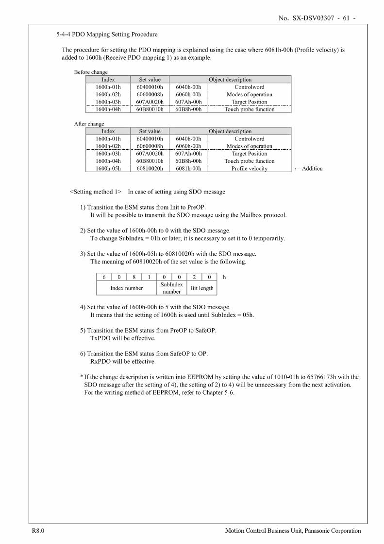
No. SX-DSV03307 - 61 -
R8.0 Motion Control Business Unit, Panasonic Corporation
5-4-4 PDO Mapping Setting Procedure
The procedure for setting the PDO mapping is explained using the case where 6081h-00h (Profile velocity) is added to 1600h (Receive PDO mapping 1) as an example.
Before change Index Set value Object description
1600h-01h 60400010h 6040h-00h Controlword 1600h-02h 60600008h 6060h-00h Modes of operation 1600h-03h 607A0020h 607Ah-00h Target Position 1600h-04h 60B80010h 60B8h-00h Touch probe function
After change
Index Set value Object description 1600h-01h 60400010h 6040h-00h Controlword 1600h-02h 60600008h 6060h-00h Modes of operation 1600h-03h 607A0020h 607Ah-00h Target Position 1600h-04h 60B80010h 60B8h-00h Touch probe function 1600h-05h 60810020h 6081h-00h Profile velocity ← Addition
<Setting method 1> In case of setting using SDO message
1) Transition the ESM status from Init to PreOP. It will be possible to transmit the SDO message using the Mailbox protocol.
2) Set the value of 1600h-00h to 0 with the SDO message.
To change SubIndex = 01h or later, it is necessary to set it to 0 temporarily. 3) Set the value of 1600h-05h to 60810020h with the SDO message.
The meaning of 60810020h of the set value is the following.
6 0 8 1 0 0 2 0 h
Index number SubIndex number Bit length
4) Set the value of 1600h-00h to 5 with the SDO message.
It means that the setting of 1600h is used until SubIndex = 05h. 5) Transition the ESM status from PreOP to SafeOP.
TxPDO will be effective. 6) Transition the ESM status from SafeOP to OP.
RxPDO will be effective. * If the change description is written into EEPROM by setting the value of 1010-01h to 65766173h with the
SDO message after the setting of 4), the setting of 2) to 4) will be unnecessary from the next activation. For the writing method of EEPROM, refer to Chapter 5-6.
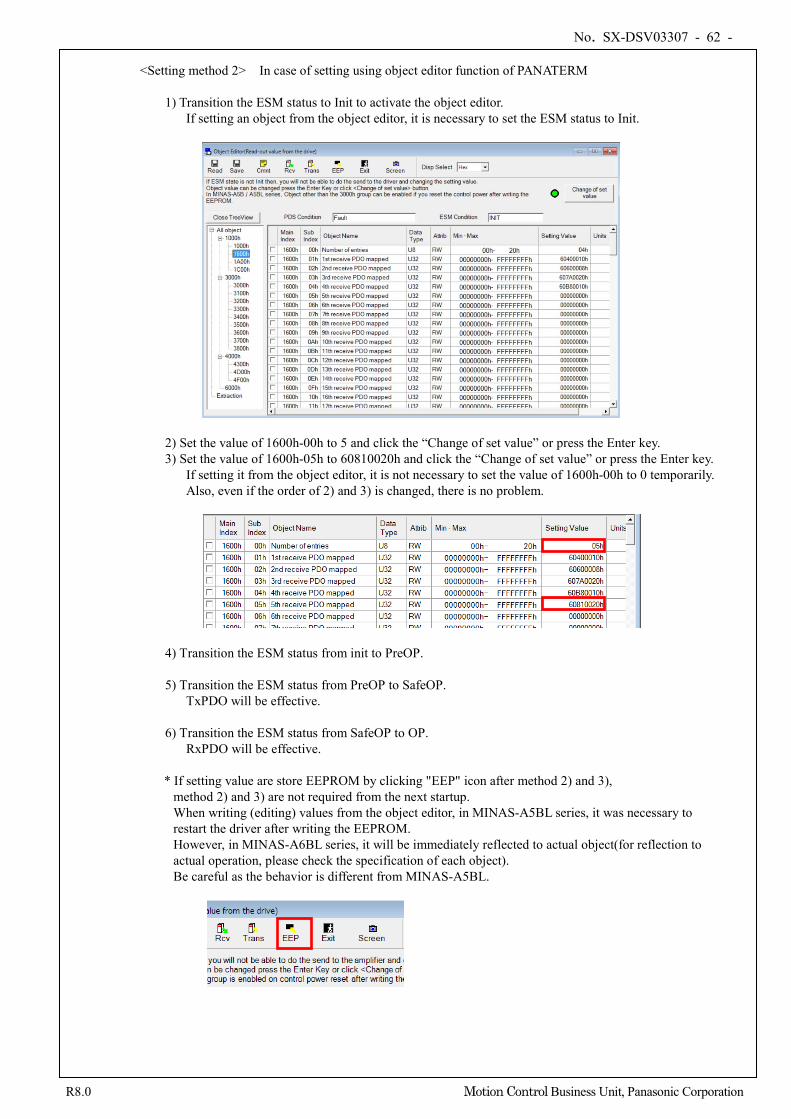
No. SX-DSV03307 - 62 -
R8.0 Motion Control Business Unit, Panasonic Corporation
<Setting method 2> In case of setting using object editor function of PANATERM
1) Transition the ESM status to Init to activate the object editor. If setting an object from the object editor, it is necessary to set the ESM status to Init.
2) Set the value of 1600h-00h to 5 and click the “Change of set value” or press the Enter key. 3) Set the value of 1600h-05h to 60810020h and click the “Change of set value” or press the Enter key.
If setting it from the object editor, it is not necessary to set the value of 1600h-00h to 0 temporarily. Also, even if the order of 2) and 3) is changed, there is no problem.
4) Transition the ESM status from init to PreOP. 5) Transition the ESM status from PreOP to SafeOP.
TxPDO will be effective. 6) Transition the ESM status from SafeOP to OP.
RxPDO will be effective.
* If setting value are store EEPROM by clicking "EEP" icon after method 2) and 3), method 2) and 3) are not required from the next startup. When writing (editing) values from the object editor, in MINAS-A5BL series, it was necessary to restart the driver after writing the EEPROM. However, in MINAS-A6BL series, it will be immediately reflected to actual object(for reflection to actual operation, please check the specification of each object). Be careful as the behavior is different from MINAS-A5BL.
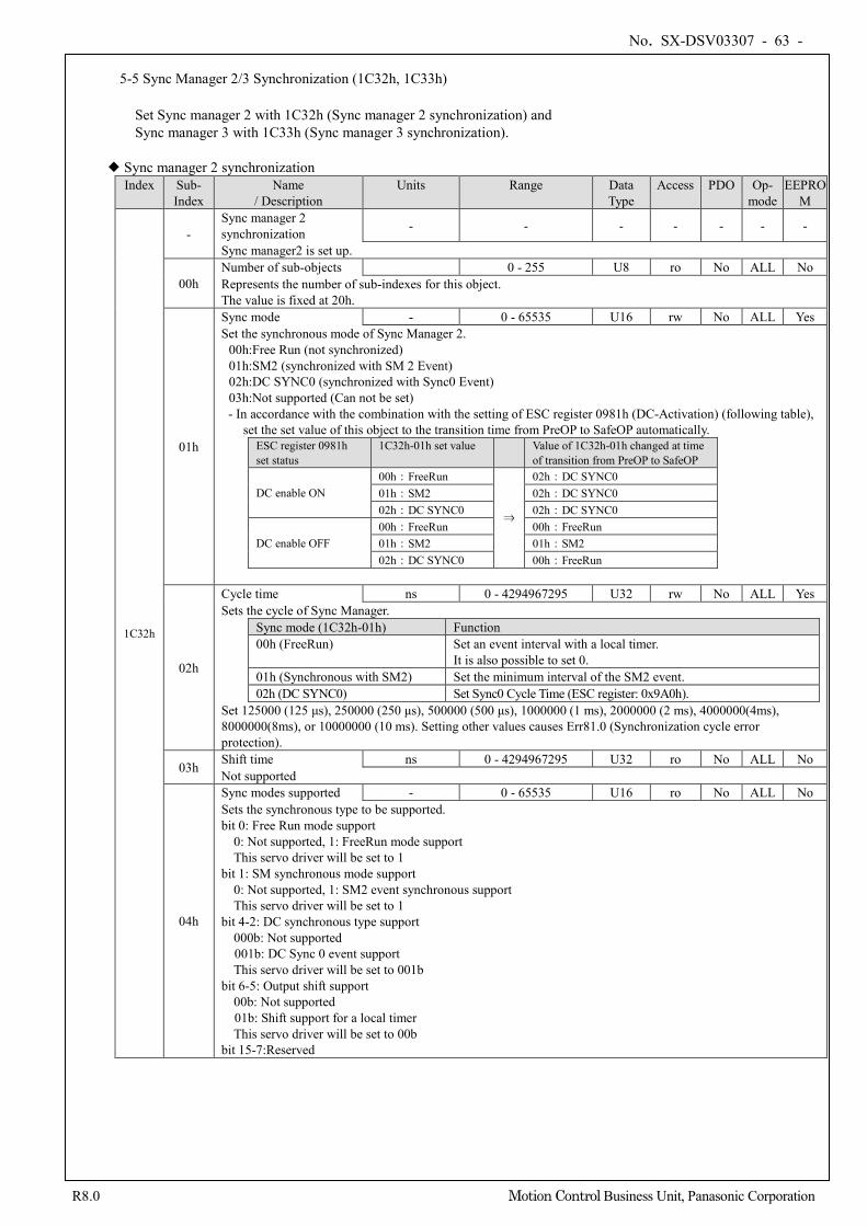
No. SX-DSV03307 - 63 -
R8.0 Motion Control Business Unit, Panasonic Corporation
5-5 Sync Manager 2/3 Synchronization (1C32h, 1C33h)
Set Sync manager 2 with 1C32h (Sync manager 2 synchronization) and Sync manager 3 with 1C33h (Sync manager 3 synchronization).
Sync manager 2 synchronization
Index Sub- Index
Name / Description
Units Range Data Type
Access PDO Op- mode
EEPROM
1C32h
- Sync manager 2 synchronization - - - - - - -
Sync manager2 is set up.
00h Number of sub-objects 0 - 255 U8 ro No ALL No Represents the number of sub-indexes for this object. The value is fixed at 20h.
01h
Sync mode - 0 - 65535 U16 rw No ALL Yes Set the synchronous mode of Sync Manager 2.
00h:Free Run (not synchronized) 01h:SM2 (synchronized with SM 2 Event) 02h:DC SYNC0 (synchronized with Sync0 Event) 03h:Not supported (Can not be set) - In accordance with the combination with the setting of ESC register 0981h (DC-Activation) (following table),
set the set value of this object to the transition time from PreOP to SafeOP automatically. ESC register 0981h set status
1C32h-01h set value Value of 1C32h-01h changed at time of transition from PreOP to SafeOP
DC enable ON 00h:FreeRun
⇒
02h:DC SYNC0 01h:SM2 02h:DC SYNC0 02h:DC SYNC0 02h:DC SYNC0
DC enable OFF 00h:FreeRun 00h:FreeRun 01h:SM2 01h:SM2 02h:DC SYNC0 00h:FreeRun
02h
Cycle time ns 0 - 4294967295 U32 rw No ALL Yes Sets the cycle of Sync Manager.
Sync mode (1C32h-01h) Function 00h (FreeRun) Set an event interval with a local timer.
It is also possible to set 0. 01h (Synchronous with SM2) Set the minimum interval of the SM2 event. 02h (DC SYNC0) Set Sync0 Cycle Time (ESC register: 0x9A0h).
Set 125000 (125 μs), 250000 (250 μs), 500000 (500 μs), 1000000 (1 ms), 2000000 (2 ms), 4000000(4ms), 8000000(8ms), or 10000000 (10 ms). Setting other values causes Err81.0 (Synchronization cycle error protection).
03h Shift time ns 0 - 4294967295 U32 ro No ALL No Not supported
04h
Sync modes supported - 0 - 65535 U16 ro No ALL No Sets the synchronous type to be supported. bit 0: Free Run mode support
0: Not supported, 1: FreeRun mode support This servo driver will be set to 1
bit 1: SM synchronous mode support 0: Not supported, 1: SM2 event synchronous support This servo driver will be set to 1
bit 4-2: DC synchronous type support 000b: Not supported 001b: DC Sync 0 event support This servo driver will be set to 001b
bit 6-5: Output shift support 00b: Not supported 01b: Shift support for a local timer This servo driver will be set to 00b
bit 15-7:Reserved
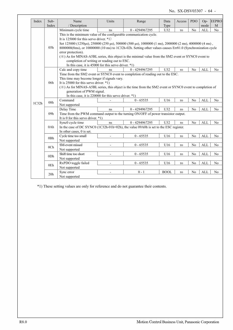
No. SX-DSV03307 - 64 -
R8.0 Motion Control Business Unit, Panasonic Corporation
Index Sub-
Index Name
/ Description Units Range Data
Type Access PDO Op-
mode EEPRO
M
1C32h
05h
Minimum cycle time ns 0 - 4294967295 U32 ro No ALL No This is the minimum value of the configurable communication cycle. It is 125000 for this servo driver. *1) Set 125000 (1250μs), 250000 (250 μs), 500000 (500 μs), 1000000 (1 ms), 2000000 (2 ms), 4000000 (4 ms) , 8000000(8ms), or 10000000 (10 ms) to 1C32h-02h. Setting other values causes Err81.0 (Synchronization cycle error protection). (※) As for MINAS-A5BL series, this object is the minimal value from the SM2 event or SYNC0 event to
completion of writing or reading out to ESC. In this case, it is 45000 for this servo driver. *1)
06h
Calc and copy time ns 0 - 4294967295 U32 ro No ALL No Time from the SM2 event or SYNC0 event to completion of reading out to the ESC. This time may become longer if signals vary. It is 25000 for this servo driver. *1) (※) As for MINAS-A5BL series, this object is the time from the SM2 event or SYNC0 event to completion of
generation of PWM signal. In this case, it is 220000 for this servo driver. *1)
08h Command - 0 - 65535 U16 ro No ALL No Not supported
09h Delay Time ns 0 - 4294967295 U32 ro No ALL No Time from the PWM command output to the turning ON/OFF of power transistor output. It is 0 for this servo driver. *1)
0Ah Sync0 cycle time ns 0 - 4294967295 U32 ro No ALL No In the case of DC SYNC0 (1C32h-01h=02h), the value 09A0h is set to the ESC register. In other cases, 0 is set.
0Bh Cycle time too small - 0 - 65535 U16 ro No ALL No Not supported
0Ch SM-event missed - 0 - 65535 U16 ro No ALL No Not supported
0Dh Shift time too short - 0 - 65535 U16 ro No ALL No Not supported
0Eh RxPDO toggle failed - 0 - 65535 U16 ro No ALL No Not supported
20h Sync error - 0 - 1 BOOL ro No ALL No Not supported
*1) These setting values are only for reference and do not guarantee their contents.
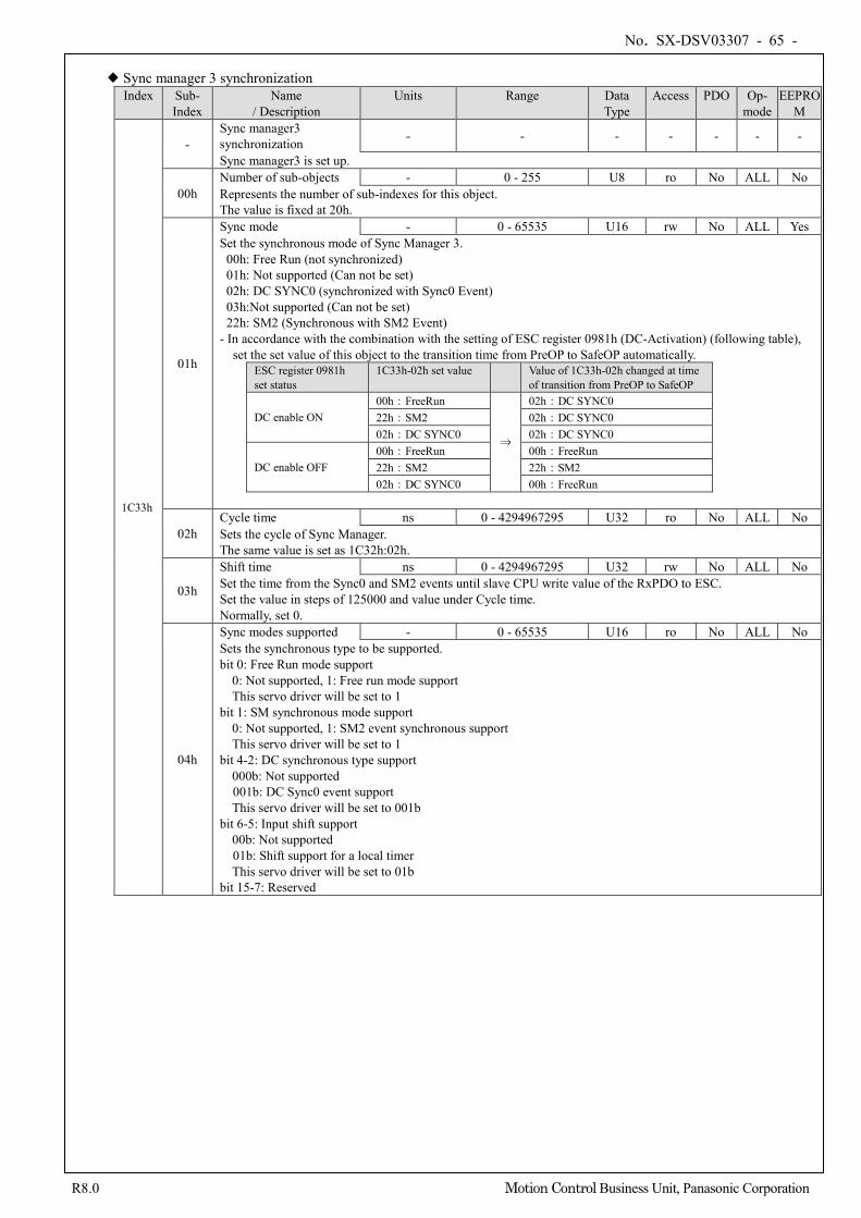
No. SX-DSV03307 - 65 -
R8.0 Motion Control Business Unit, Panasonic Corporation
Sync manager 3 synchronization
Index Sub- Index
Name / Description
Units Range Data Type
Access PDO Op- mode
EEPROM
1C33h
- Sync manager3 synchronization - - - - - - -
Sync manager3 is set up.
00h Number of sub-objects - 0 - 255 U8 ro No ALL No Represents the number of sub-indexes for this object. The value is fixed at 20h.
01h
Sync mode - 0 - 65535 U16 rw No ALL Yes Set the synchronous mode of Sync Manager 3.
00h: Free Run (not synchronized) 01h: Not supported (Can not be set) 02h: DC SYNC0 (synchronized with Sync0 Event) 03h:Not supported (Can not be set) 22h: SM2 (Synchronous with SM2 Event)
- In accordance with the combination with the setting of ESC register 0981h (DC-Activation) (following table), set the set value of this object to the transition time from PreOP to SafeOP automatically.
ESC register 0981h set status
1C33h-02h set value Value of 1C33h-02h changed at time of transition from PreOP to SafeOP
DC enable ON 00h:FreeRun
⇒
02h:DC SYNC0 22h:SM2 02h:DC SYNC0 02h:DC SYNC0 02h:DC SYNC0
DC enable OFF 00h:FreeRun 00h:FreeRun 22h:SM2 22h:SM2 02h:DC SYNC0 00h:FreeRun
02h Cycle time ns 0 - 4294967295 U32 ro No ALL No Sets the cycle of Sync Manager. The same value is set as 1C32h:02h.
03h
Shift time ns 0 - 4294967295 U32 rw No ALL No Set the time from the Sync0 and SM2 events until slave CPU write value of the RxPDO to ESC. Set the value in steps of 125000 and value under Cycle time. Normally, set 0.
04h
Sync modes supported - 0 - 65535 U16 ro No ALL No Sets the synchronous type to be supported. bit 0: Free Run mode support
0: Not supported, 1: Free run mode support This servo driver will be set to 1
bit 1: SM synchronous mode support 0: Not supported, 1: SM2 event synchronous support This servo driver will be set to 1
bit 4-2: DC synchronous type support 000b: Not supported 001b: DC Sync0 event support This servo driver will be set to 001b
bit 6-5: Input shift support 00b: Not supported 01b: Shift support for a local timer This servo driver will be set to 01b
bit 15-7: Reserved
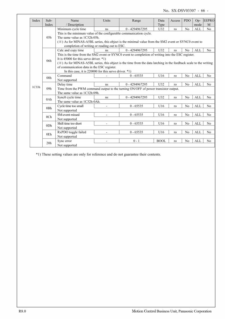
No. SX-DSV03307 - 66 -
R8.0 Motion Control Business Unit, Panasonic Corporation
Index Sub-
Index Name
/ Description Units Range Data
Type Access PDO Op-
mode EEPRO
M
1C33h
05h
Minimum cycle time ns 0 - 4294967295 U32 ro No ALL No This is the minimum value of the configurable communication cycle. The same value as 1C32h:05h. (※) As for MINAS-A5BL series, this object is the minimal value from the SM2 event or SYNC0 event to
completion of writing or reading out to ESC.
06h
Calc and copy time ns 0 - 4294967295 U32 ro No ALL No This is the time from the SM2 event or SYNC0 event to completion of writing into the ESC register. It is 45000 for this servo driver. *1) (※) As for MINAS-A5BL series, this object is the time from the data latching in the feedback scale to the writing of communication data in the ESC register.
In this case, it is 220000 for this servo driver. *1)
08h Command - 0 - 65535 U16 ro No ALL No Not supported
09h Delay time ns 0 - 4294967295 U32 ro No ALL No Time from the PWM command output to the turning ON/OFF of power transistor output. The same value as 1C32h:09h.
0Ah Sync0 cycle time ns 0 - 4294967295 U32 ro No ALL No The same value as 1C32h-0Ah.
0Bh Cycle time too small - 0 - 65535 U16 ro No ALL No Not supported
0Ch SM-event missed - 0 - 65535 U16 ro No ALL No Not supported
0Dh Shift time too short - 0 - 65535 U16 ro No ALL No Not supported
0Eh RxPDO toggle failed - 0 - 65535 U16 ro No ALL No Not supported
20h Sync error - 0 - 1 BOOL ro No ALL No Not supported
*1) These setting values are only for reference and do not guarantee their contents.
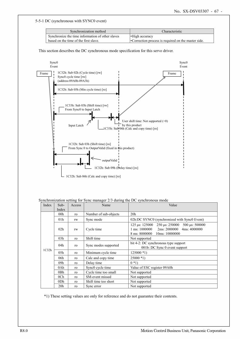
No. SX-DSV03307 - 67 -
R8.0 Motion Control Business Unit, Panasonic Corporation
5-5-1 DC (synchronous with SYNC0 event)
Synchronization method Characteristic Synchronize the time information of other slaves based on the time of the first slave.
• High accuracy • Correction process is required on the master side.
This section describes the DC synchronous mode specification for this servo driver.
Synchronization setting for Sync manager 2/3 during the DC synchronous mode Index Sub-
Index Access Name Value
1C32h
00h ro Number of sub-objects 20h 01h rw Sync mode 02h:DC SYNC0 (synchronized with Sync0 Event)
02h rw Cycle time 125 μs: 125000 250 μs: 250000 500 μs: 500000 1 ms: 1000000 2ms: 2000000 4ms: 4000000 8 ms: 8000000 10ms: 10000000
03h ro Shift time Not supported
04h ro Sync modes supported bit 4-2: DC synchronous type support 001b: DC Sync 0 event support
05h ro Minimum cycle time 125000 *1) 06h ro Calc and copy time 25000 *1) 09h ro Delay time 0 *1) 0Ah ro Sync0 cycle time Value of ESC register 09A0h 0Bh ro Cycle time too small Not supported 0Ch ro SM-event missed Not supported 0Dh ro Shift time too short Not supported 20h ro Sync error Not supported
*1) These setting values are only for reference and do not guarantee their contents.
Sync0 Event
Frame
Sync0 Event
Frame 1C32h: Sub 02h (Cycle time) [rw] Sync0 cycle time [rw] (address:09A0h-09A3h)
1C32h: Sub 05h (Min cycle time) [ro]
1C33h: Sub 03h (Shift time) [rw] From Sync0 to Input Latch
1C33h: Sub 06h (Calc and copy time) [ro]
User shift time: Not supported (=0) by this product Input Latch
1C32h: Sub 03h (Shift time) [ro] From Sync 0 to OutputValid (fixed in this product)
1C32h: Sub 06h (Calc and copy time) [ro]
1C32h: Sub 09h (Delay time) [ro]
outputValid
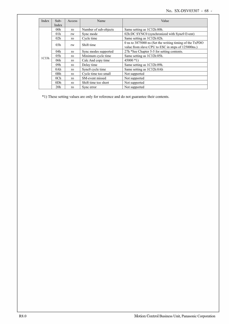
No. SX-DSV03307 - 68 -
R8.0 Motion Control Business Unit, Panasonic Corporation
Index Sub-
Index Access Name Value
1C33h
00h ro Number of sub-objects Same setting as 1C32h:00h. 01h rw Sync mode 02h:DC SYNC0 (synchronized with Sync0 Event) 02h ro Cycle time Same setting as 1C32h:02h.
03h rw Shift time 0 ns to 3875000 ns (Set the writing timing of the TxPDO value from slave CPU to ESC in steps of 125000ns.)
04h ro Sync modes supported 27h *See Chapter 5-5 for setting contents. 05h ro Minimum cycle time Same setting as 1C32h:05h. 06h ro Calc And copy time 45000 *1) 09h ro Delay time Same setting as 1C32h:09h. 0Ah ro Sync0 cycle time Same setting as 1C32h:0Ah 0Bh ro Cycle time too small Not supported 0Ch ro SM-event missed Not supported 0Dh ro Shift time too short Not supported 20h ro Sync error Not supported
*1) These setting values are only for reference and do not guarantee their contents.
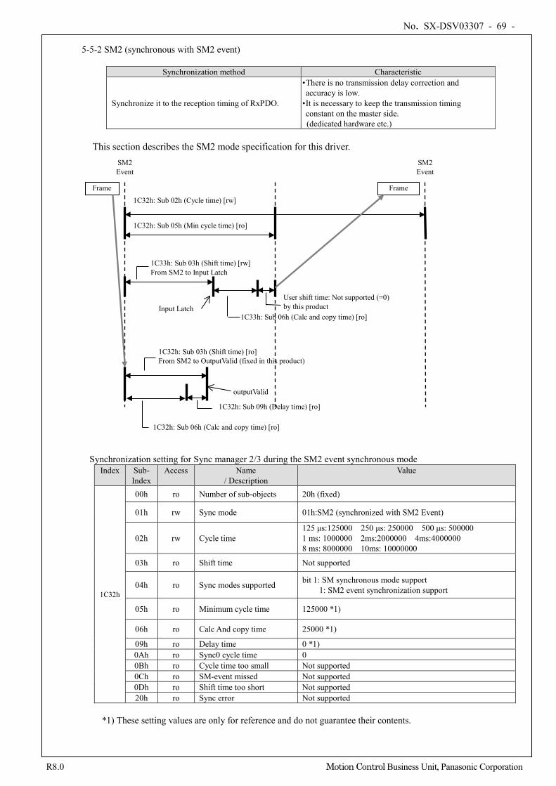
No. SX-DSV03307 - 69 -
R8.0 Motion Control Business Unit, Panasonic Corporation
5-5-2 SM2 (synchronous with SM2 event)
Synchronization method Characteristic
Synchronize it to the reception timing of RxPDO.
• There is no transmission delay correction and accuracy is low.
• It is necessary to keep the transmission timing constant on the master side.
(dedicated hardware etc.)
This section describes the SM2 mode specification for this driver.
Synchronization setting for Sync manager 2/3 during the SM2 event synchronous mode Index Sub-
Index Access Name
/ Description Value
1C32h
00h ro Number of sub-objects 20h (fixed)
01h rw Sync mode 01h:SM2 (synchronized with SM2 Event)
02h rw Cycle time 125 μs:125000 250 μs: 250000 500 μs: 500000 1 ms: 1000000 2ms:2000000 4ms:4000000 8 ms: 8000000 10ms: 10000000
03h ro Shift time Not supported
04h ro Sync modes supported bit 1: SM synchronous mode support 1: SM2 event synchronization support
05h ro Minimum cycle time 125000 *1)
06h ro Calc And copy time 25000 *1)
09h ro Delay time 0 *1) 0Ah ro Sync0 cycle time 0 0Bh ro Cycle time too small Not supported 0Ch ro SM-event missed Not supported 0Dh ro Shift time too short Not supported 20h ro Sync error Not supported
*1) These setting values are only for reference and do not guarantee their contents.
SM2 Event
Frame
SM2 Event
Frame 1C32h: Sub 02h (Cycle time) [rw]
1C32h: Sub 05h (Min cycle time) [ro]
1C33h: Sub 03h (Shift time) [rw] From SM2 to Input Latch
1C33h: Sub 06h (Calc and copy time) [ro]
User shift time: Not supported (=0) by this product Input Latch
1C32h: Sub 03h (Shift time) [ro] From SM2 to OutputValid (fixed in this product)
1C32h: Sub 06h (Calc and copy time) [ro]
1C32h: Sub 09h (Delay time) [ro]
outputValid
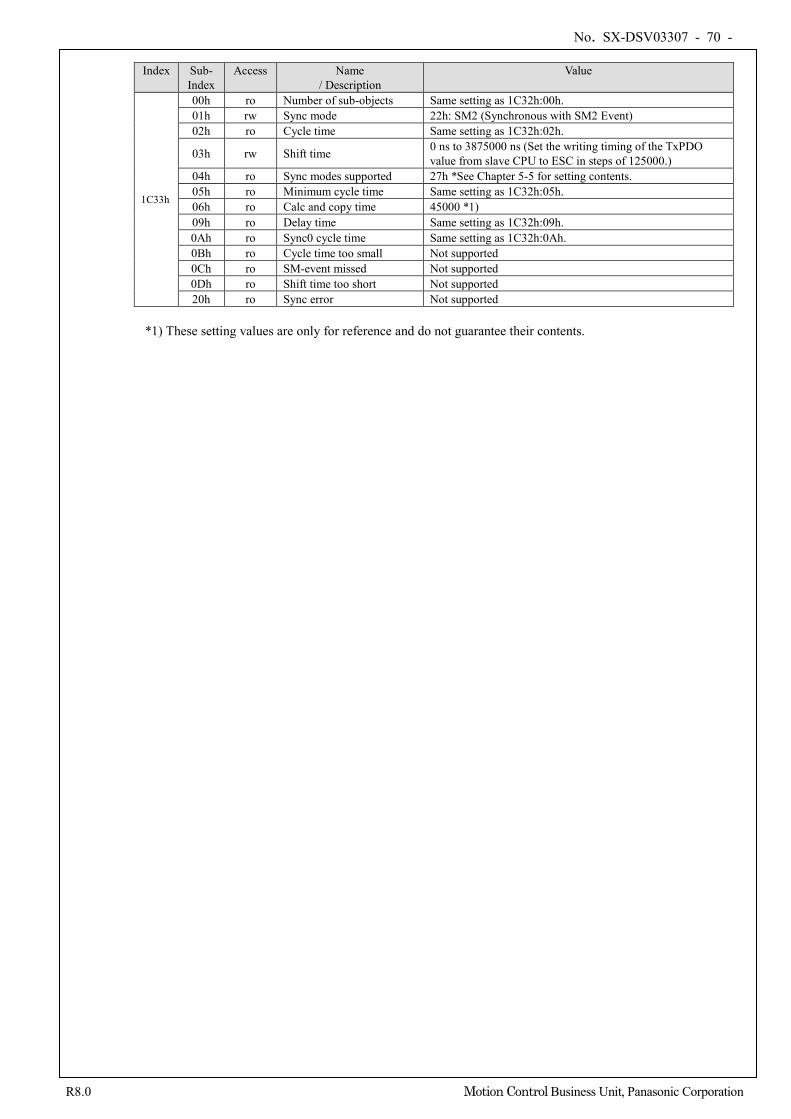
No. SX-DSV03307 - 70 -
R8.0 Motion Control Business Unit, Panasonic Corporation
Index Sub-
Index Access Name
/ Description Value
1C33h
00h ro Number of sub-objects Same setting as 1C32h:00h. 01h rw Sync mode 22h: SM2 (Synchronous with SM2 Event) 02h ro Cycle time Same setting as 1C32h:02h.
03h rw Shift time 0 ns to 3875000 ns (Set the writing timing of the TxPDO value from slave CPU to ESC in steps of 125000.)
04h ro Sync modes supported 27h *See Chapter 5-5 for setting contents. 05h ro Minimum cycle time Same setting as 1C32h:05h. 06h ro Calc and copy time 45000 *1) 09h ro Delay time Same setting as 1C32h:09h. 0Ah ro Sync0 cycle time Same setting as 1C32h:0Ah. 0Bh ro Cycle time too small Not supported 0Ch ro SM-event missed Not supported 0Dh ro Shift time too short Not supported 20h ro Sync error Not supported
*1) These setting values are only for reference and do not guarantee their contents.
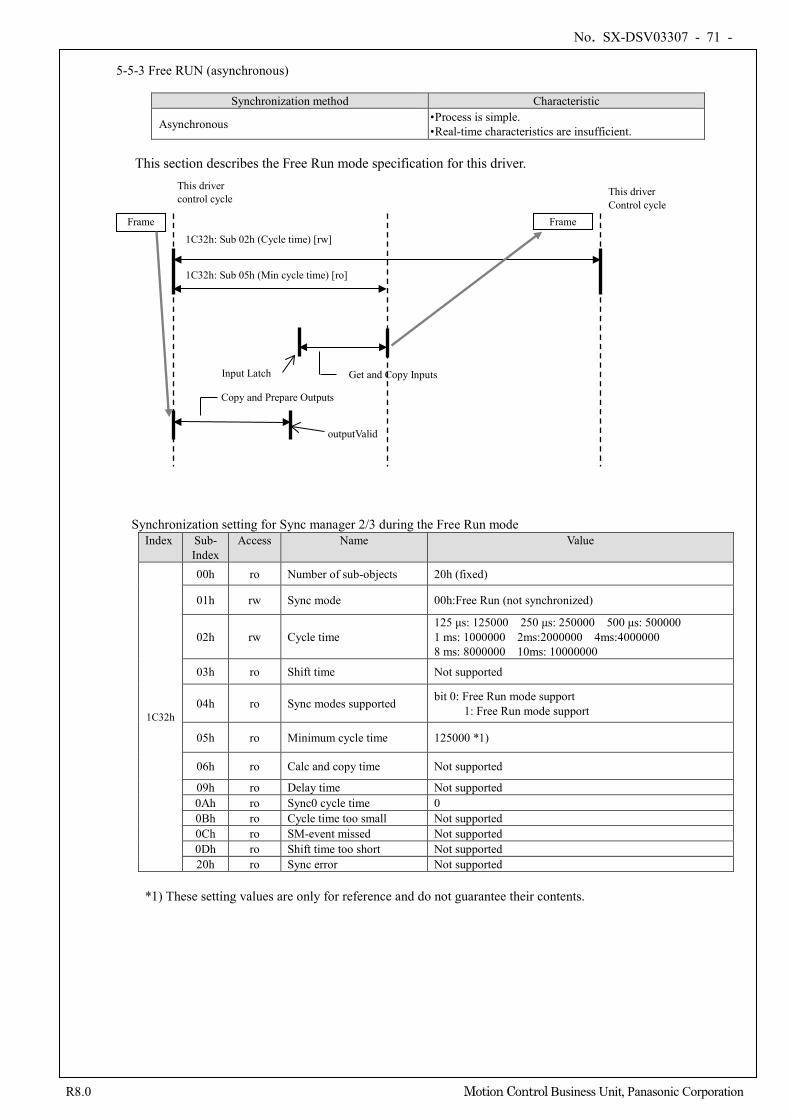
No. SX-DSV03307 - 71 -
R8.0 Motion Control Business Unit, Panasonic Corporation
5-5-3 Free RUN (asynchronous)
Synchronization method Characteristic
Asynchronous • Process is simple. • Real-time characteristics are insufficient.
This section describes the Free Run mode specification for this driver.
Synchronization setting for Sync manager 2/3 during the Free Run mode Index Sub-
Index Access Name Value
1C32h
00h ro Number of sub-objects 20h (fixed)
01h rw Sync mode 00h:Free Run (not synchronized)
02h rw Cycle time 125 μs: 125000 250 μs: 250000 500 μs: 500000 1 ms: 1000000 2ms:2000000 4ms:4000000 8 ms: 8000000 10ms: 10000000
03h ro Shift time Not supported
04h ro Sync modes supported bit 0: Free Run mode support 1: Free Run mode support
05h ro Minimum cycle time 125000 *1)
06h ro Calc and copy time Not supported
09h ro Delay time Not supported 0Ah ro Sync0 cycle time 0 0Bh ro Cycle time too small Not supported 0Ch ro SM-event missed Not supported 0Dh ro Shift time too short Not supported 20h ro Sync error Not supported
*1) These setting values are only for reference and do not guarantee their contents.
This driver control cycle
Frame
This driver Control cycle
Frame 1C32h: Sub 02h (Cycle time) [rw]
1C32h: Sub 05h (Min cycle time) [ro]
Get and Copy Inputs Input Latch
Copy and Prepare Outputs
outputValid
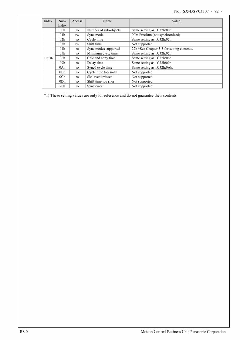
No. SX-DSV03307 - 72 -
R8.0 Motion Control Business Unit, Panasonic Corporation
Index Sub- Index
Access Name Value
1C33h
00h ro Number of sub-objects Same setting as 1C32h:00h. 01h rw Sync mode 00h: FreeRun (not synchronized) 02h ro Cycle time Same setting as 1C32h:02h. 03h rw Shift time Not supported 04h ro Sync modes supported 27h *See Chapter 5-5 for setting contents. 05h ro Minimum cycle time Same setting as 1C32h:05h. 06h ro Calc and copy time Same setting as 1C32h:06h. 09h ro Delay time Same setting as 1C32h:09h. 0Ah ro Sync0 cycle time Same setting as 1C32h:0Ah. 0Bh ro Cycle time too small Not supported 0Ch ro SM-event missed Not supported 0Dh ro Shift time too short Not supported 20h ro Sync error Not supported
*1) These setting values are only for reference and do not guarantee their contents.
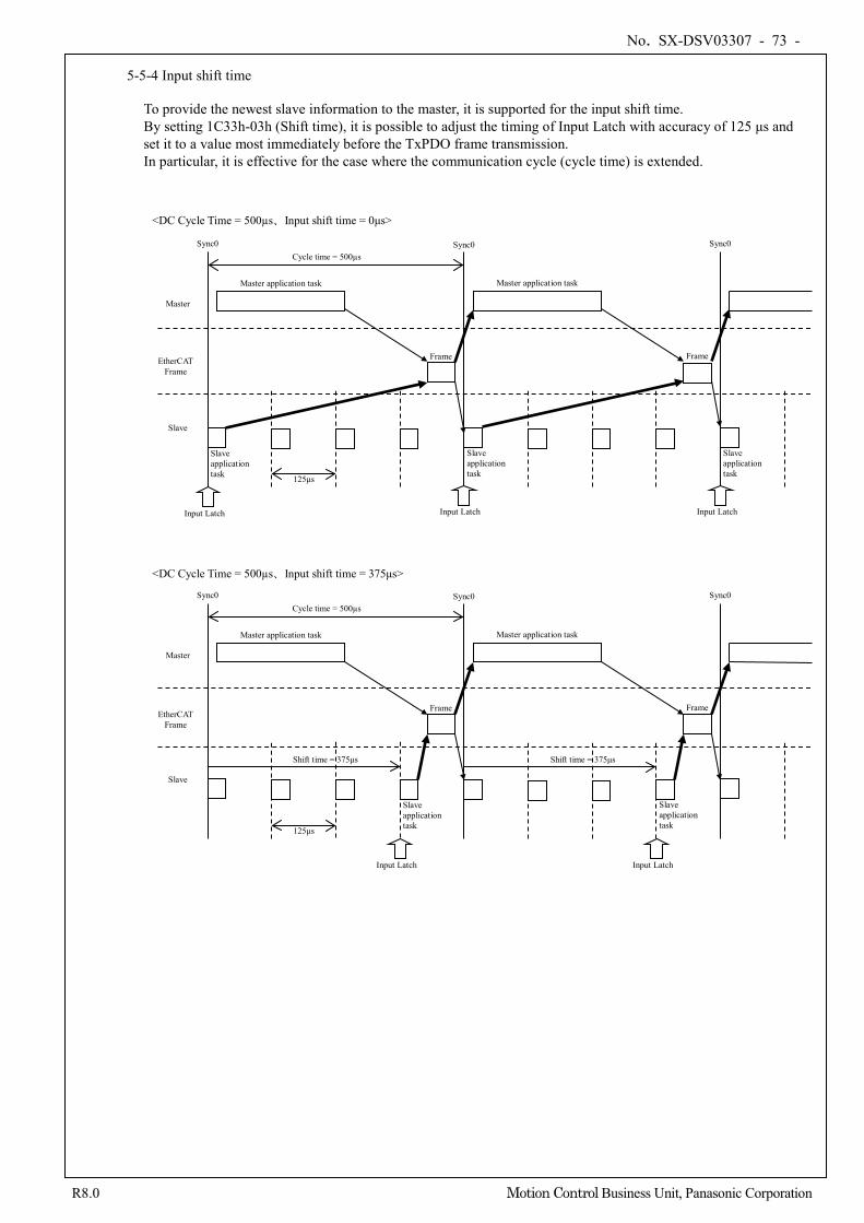
No. SX-DSV03307 - 73 -
R8.0 Motion Control Business Unit, Panasonic Corporation
5-5-4 Input shift time To provide the newest slave information to the master, it is supported for the input shift time. By setting 1C33h-03h (Shift time), it is possible to adjust the timing of Input Latch with accuracy of 125 μs and set it to a value most immediately before the TxPDO frame transmission. In particular, it is effective for the case where the communication cycle (cycle time) is extended.
Sync0
<DC Cycle Time = 500µs、Input shift time = 375μs>
Input Latch
Master
EtherCAT Frame
Slave
Frame
Slave application task
Master application task Master application task
Frame
Slave application task
Sync0 Sync0 Cycle time = 500µs
125μs
Slave application task
Slave application task 125μs
Slave application task
Input Latch
Master
EtherCAT Frame
Slave
Master application task
Cycle time = 500µs Sync0 Sync0 Sync0
Frame Frame
Master application task
<DC Cycle Time = 500µs、Input shift time = 0μs>
Shift time = 375μs
Input Latch Input Latch
Shift time = 375μs
Input Latch
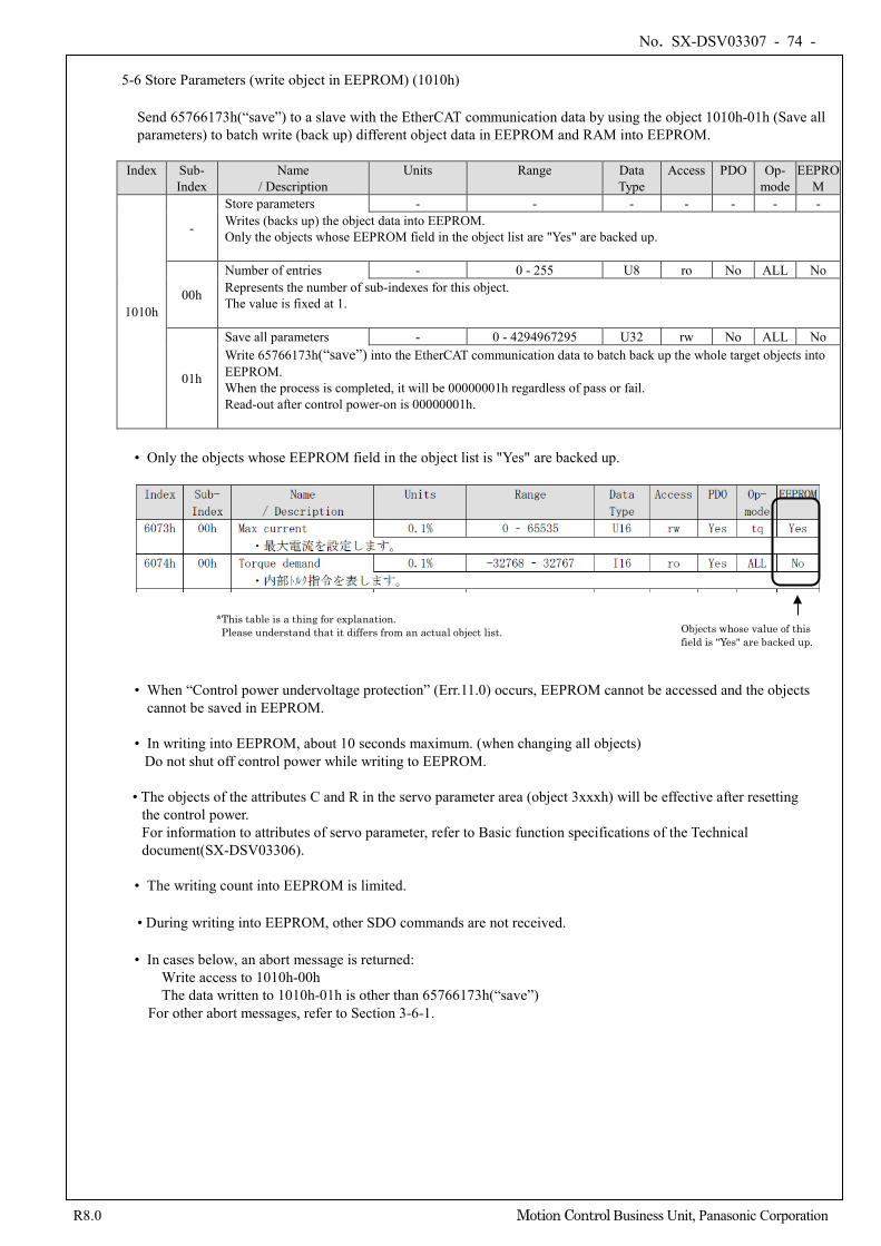
No. SX-DSV03307 - 74 -
R8.0 Motion Control Business Unit, Panasonic Corporation
5-6 Store Parameters (write object in EEPROM) (1010h)
Send 65766173h(“save”) to a slave with the EtherCAT communication data by using the object 1010h-01h (Save all parameters) to batch write (back up) different object data in EEPROM and RAM into EEPROM.
Index Sub-
Index Name
/ Description Units Range Data
Type Access PDO Op-
mode EEPRO
M
1010h
-
Store parameters - - - - - - - Writes (backs up) the object data into EEPROM. Only the objects whose EEPROM field in the object list are "Yes" are backed up.
00h
Number of entries - 0 - 255 U8 ro No ALL No Represents the number of sub-indexes for this object. The value is fixed at 1.
01h
Save all parameters - 0 - 4294967295 U32 rw No ALL No Write 65766173h(“save”) into the EtherCAT communication data to batch back up the whole target objects into EEPROM. When the process is completed, it will be 00000001h regardless of pass or fail. Read-out after control power-on is 00000001h.
• Only the objects whose EEPROM field in the object list is "Yes" are backed up.
• When “Control power undervoltage protection” (Err.11.0) occurs, EEPROM cannot be accessed and the objects
cannot be saved in EEPROM. • In writing into EEPROM, about 10 seconds maximum. (when changing all objects) Do not shut off control power while writing to EEPROM.
• The objects of the attributes C and R in the servo parameter area (object 3xxxh) will be effective after resetting the control power. For information to attributes of servo parameter, refer to Basic function specifications of the Technical document(SX-DSV03306).
• The writing count into EEPROM is limited. • During writing into EEPROM, other SDO commands are not received. • In cases below, an abort message is returned:
Write access to 1010h-00h The data written to 1010h-01h is other than 65766173h(“save”)
For other abort messages, refer to Section 3-6-1.
Objects whose value of this field is "Yes" are backed up.
*This table is a thing for explanation. Please understand that it differs from an actual object list.
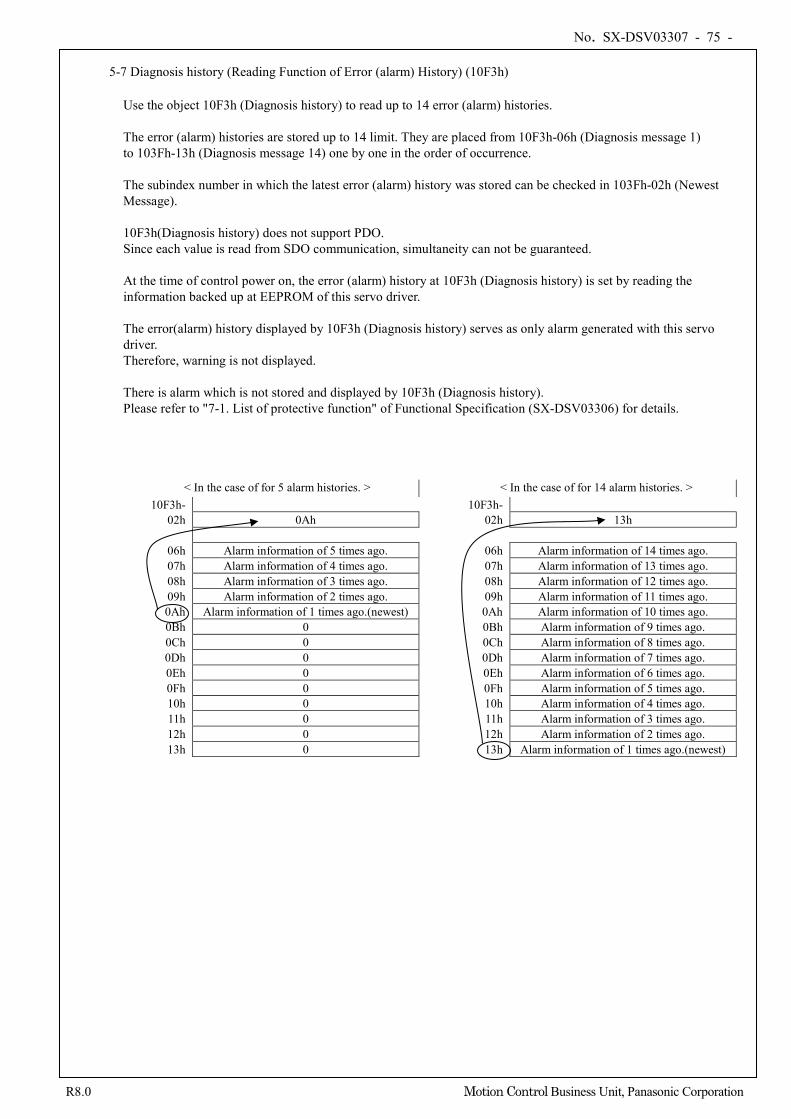
No. SX-DSV03307 - 75 -
R8.0 Motion Control Business Unit, Panasonic Corporation
5-7 Diagnosis history (Reading Function of Error (alarm) History) (10F3h)
Use the object 10F3h (Diagnosis history) to read up to 14 error (alarm) histories.
The error (alarm) histories are stored up to 14 limit. They are placed from 10F3h-06h (Diagnosis message 1) to 103Fh-13h (Diagnosis message 14) one by one in the order of occurrence. The subindex number in which the latest error (alarm) history was stored can be checked in 103Fh-02h (Newest Message). 10F3h(Diagnosis history) does not support PDO. Since each value is read from SDO communication, simultaneity can not be guaranteed. At the time of control power on, the error (alarm) history at 10F3h (Diagnosis history) is set by reading the information backed up at EEPROM of this servo driver. The error(alarm) history displayed by 10F3h (Diagnosis history) serves as only alarm generated with this servo driver. Therefore, warning is not displayed. There is alarm which is not stored and displayed by 10F3h (Diagnosis history). Please refer to "7-1. List of protective function" of Functional Specification (SX-DSV03306) for details.
< In the case of for 5 alarm histories. > < In the case of for 14 alarm histories. > 10F3h- 10F3h-
02h 0Ah 02h 13h
06h Alarm information of 5 times ago. 06h Alarm information of 14 times ago. 07h Alarm information of 4 times ago. 07h Alarm information of 13 times ago. 08h Alarm information of 3 times ago. 08h Alarm information of 12 times ago. 09h Alarm information of 2 times ago. 09h Alarm information of 11 times ago. 0Ah Alarm information of 1 times ago.(newest) 0Ah Alarm information of 10 times ago. 0Bh 0 0Bh Alarm information of 9 times ago. 0Ch 0 0Ch Alarm information of 8 times ago. 0Dh 0 0Dh Alarm information of 7 times ago. 0Eh 0 0Eh Alarm information of 6 times ago. 0Fh 0 0Fh Alarm information of 5 times ago. 10h 0 10h Alarm information of 4 times ago. 11h 0 11h Alarm information of 3 times ago. 12h 0 12h Alarm information of 2 times ago. 13h 0 13h Alarm information of 1 times ago.(newest)
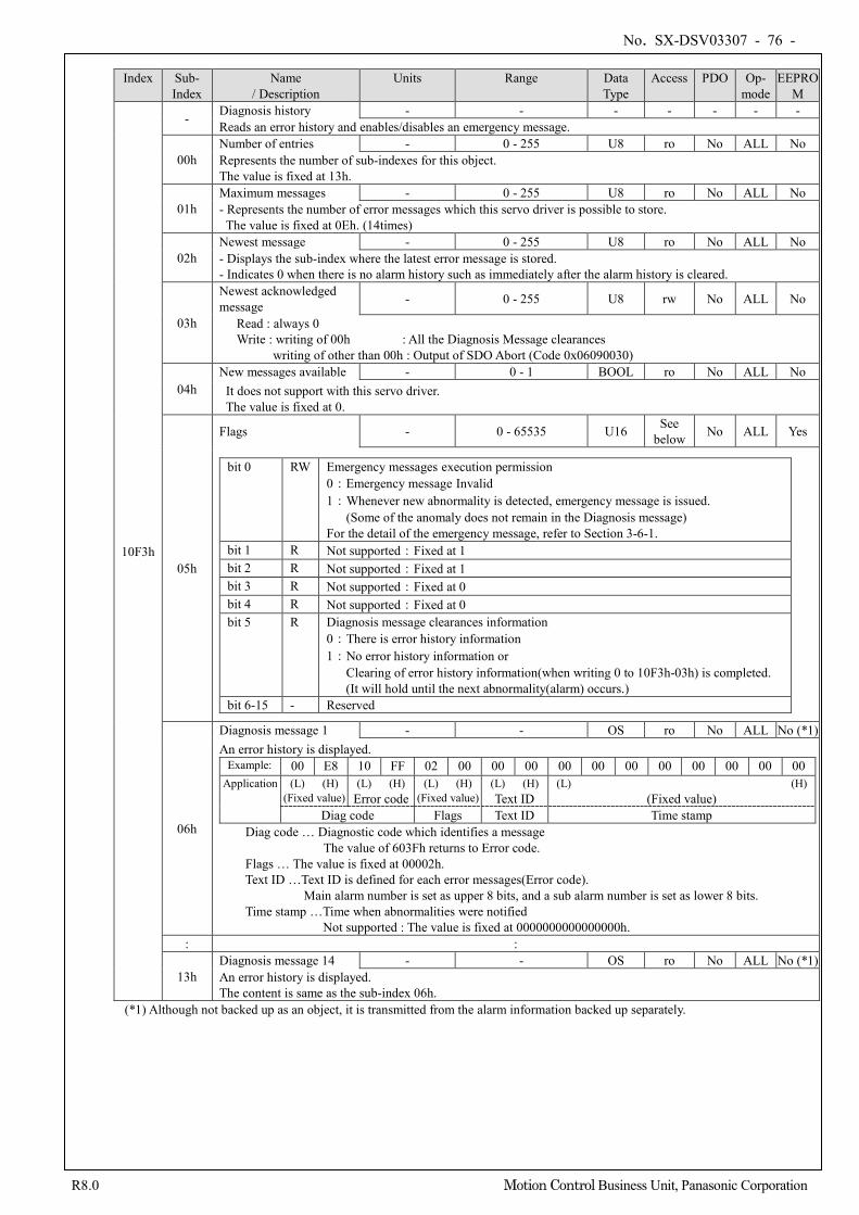
No. SX-DSV03307 - 76 -
R8.0 Motion Control Business Unit, Panasonic Corporation
Index Sub-
Index Name
/ Description Units Range Data
Type Access PDO Op-
mode EEPRO
M
10F3h
- Diagnosis history - - - - - - - Reads an error history and enables/disables an emergency message.
00h Number of entries - 0 - 255 U8 ro No ALL No Represents the number of sub-indexes for this object. The value is fixed at 13h.
01h Maximum messages - 0 - 255 U8 ro No ALL No - Represents the number of error messages which this servo driver is possible to store. The value is fixed at 0Eh. (14times)
02h Newest message - 0 - 255 U8 ro No ALL No - Displays the sub-index where the latest error message is stored. - Indicates 0 when there is no alarm history such as immediately after the alarm history is cleared.
03h
Newest acknowledged message - 0 - 255 U8 rw No ALL No
Read : always 0 Write : writing of 00h : All the Diagnosis Message clearances
writing of other than 00h : Output of SDO Abort (Code 0x06090030)
04h New messages available - 0 - 1 BOOL ro No ALL No
It does not support with this servo driver. The value is fixed at 0.
05h
Flags - 0 - 65535 U16 See below No ALL Yes
bit 0 RW Emergency messages execution permission 0:Emergency message Invalid 1:Whenever new abnormality is detected, emergency message is issued.
(Some of the anomaly does not remain in the Diagnosis message) For the detail of the emergency message, refer to Section 3-6-1.
bit 1 R Not supported:Fixed at 1 bit 2 R Not supported:Fixed at 1 bit 3 R Not supported:Fixed at 0 bit 4 R Not supported:Fixed at 0 bit 5 R Diagnosis message clearances information
0:There is error history information 1:No error history information or
Clearing of error history information(when writing 0 to 10F3h-03h) is completed. (It will hold until the next abnormality(alarm) occurs.)
bit 6-15 - Reserved
06h
Diagnosis message 1 - - OS ro No ALL No (*1) An error history is displayed. Example: 00 E8 10 FF 02 00 00 00 00 00 00 00 00 00 00 00 Application (L) (H)
(Fixed value) (L) (H)
Error code (L) (H)
(Fixed value) (L) (H) Text ID
(L) (H) (Fixed value)
Diag code Flags Text ID Time stamp Diag code … Diagnostic code which identifies a message The value of 603Fh returns to Error code. Flags … The value is fixed at 00002h.
Text ID …Text ID is defined for each error messages(Error code). Main alarm number is set as upper 8 bits, and a sub alarm number is set as lower 8 bits.
Time stamp …Time when abnormalities were notified Not supported : The value is fixed at 0000000000000000h.
: :
13h Diagnosis message 14 - - OS ro No ALL No (*1) An error history is displayed. The content is same as the sub-index 06h.
(*1) Although not backed up as an object, it is transmitted from the alarm information backed up separately.
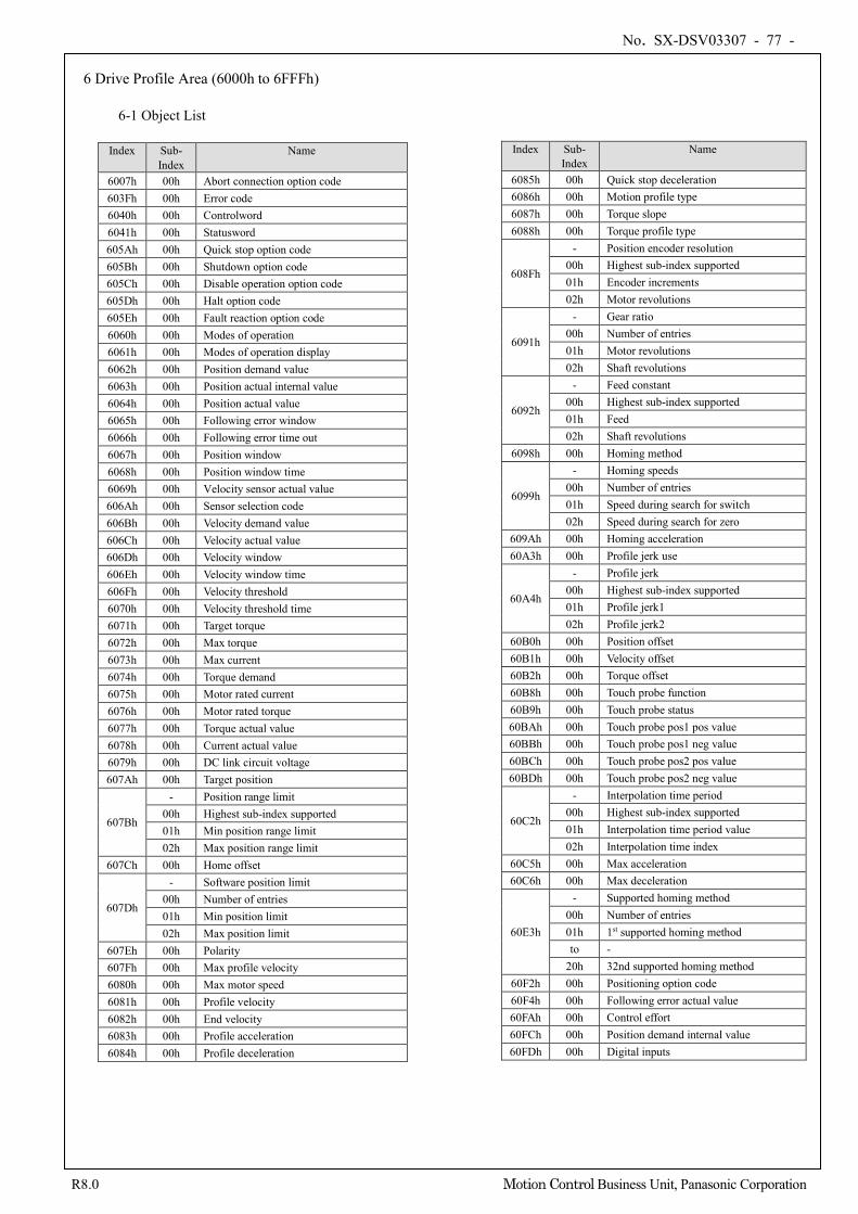
No. SX-DSV03307 - 77 -
R8.0 Motion Control Business Unit, Panasonic Corporation
6 Drive Profile Area (6000h to 6FFFh)
6-1 Object List
Index Sub- Index
Name
6085h 00h Quick stop deceleration 6086h 00h Motion profile type 6087h 00h Torque slope 6088h 00h Torque profile type
608Fh
- Position encoder resolution 00h Highest sub-index supported 01h Encoder increments 02h Motor revolutions
6091h
- Gear ratio 00h Number of entries 01h Motor revolutions 02h Shaft revolutions
6092h
- Feed constant 00h Highest sub-index supported 01h Feed 02h Shaft revolutions
6098h 00h Homing method
6099h
- Homing speeds 00h Number of entries 01h Speed during search for switch 02h Speed during search for zero
609Ah 00h Homing acceleration 60A3h 00h Profile jerk use
60A4h
- Profile jerk 00h Highest sub-index supported 01h Profile jerk1 02h Profile jerk2
60B0h 00h Position offset 60B1h 00h Velocity offset 60B2h 00h Torque offset 60B8h 00h Touch probe function 60B9h 00h Touch probe status 60BAh 00h Touch probe pos1 pos value 60BBh 00h Touch probe pos1 neg value 60BCh 00h Touch probe pos2 pos value 60BDh 00h Touch probe pos2 neg value
60C2h
- Interpolation time period 00h Highest sub-index supported 01h Interpolation time period value 02h Interpolation time index
60C5h 00h Max acceleration 60C6h 00h Max deceleration
60E3h
- Supported homing method 00h Number of entries 01h 1st supported homing method to -
20h 32nd supported homing method 60F2h 00h Positioning option code 60F4h 00h Following error actual value 60FAh 00h Control effort 60FCh 00h Position demand internal value 60FDh 00h Digital inputs
Index Sub- Index
Name
6007h 00h Abort connection option code 603Fh 00h Error code 6040h 00h Controlword 6041h 00h Statusword 605Ah 00h Quick stop option code 605Bh 00h Shutdown option code 605Ch 00h Disable operation option code 605Dh 00h Halt option code 605Eh 00h Fault reaction option code 6060h 00h Modes of operation 6061h 00h Modes of operation display 6062h 00h Position demand value 6063h 00h Position actual internal value 6064h 00h Position actual value 6065h 00h Following error window 6066h 00h Following error time out 6067h 00h Position window 6068h 00h Position window time 6069h 00h Velocity sensor actual value 606Ah 00h Sensor selection code 606Bh 00h Velocity demand value 606Ch 00h Velocity actual value 606Dh 00h Velocity window 606Eh 00h Velocity window time 606Fh 00h Velocity threshold 6070h 00h Velocity threshold time 6071h 00h Target torque 6072h 00h Max torque 6073h 00h Max current 6074h 00h Torque demand 6075h 00h Motor rated current 6076h 00h Motor rated torque 6077h 00h Torque actual value 6078h 00h Current actual value 6079h 00h DC link circuit voltage 607Ah 00h Target position
607Bh
- Position range limit 00h Highest sub-index supported 01h Min position range limit 02h Max position range limit
607Ch 00h Home offset
607Dh
- Software position limit 00h Number of entries 01h Min position limit 02h Max position limit
607Eh 00h Polarity 607Fh 00h Max profile velocity 6080h 00h Max motor speed 6081h 00h Profile velocity 6082h 00h End velocity 6083h 00h Profile acceleration 6084h 00h Profile deceleration
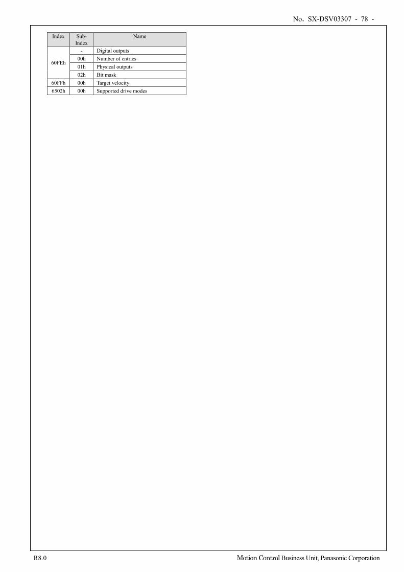
No. SX-DSV03307 - 78 -
R8.0 Motion Control Business Unit, Panasonic Corporation
Index Sub-
Index Name
60FEh
- Digital outputs 00h Number of entries 01h Physical outputs 02h Bit mask
60FFh 00h Target velocity 6502h 00h Supported drive modes
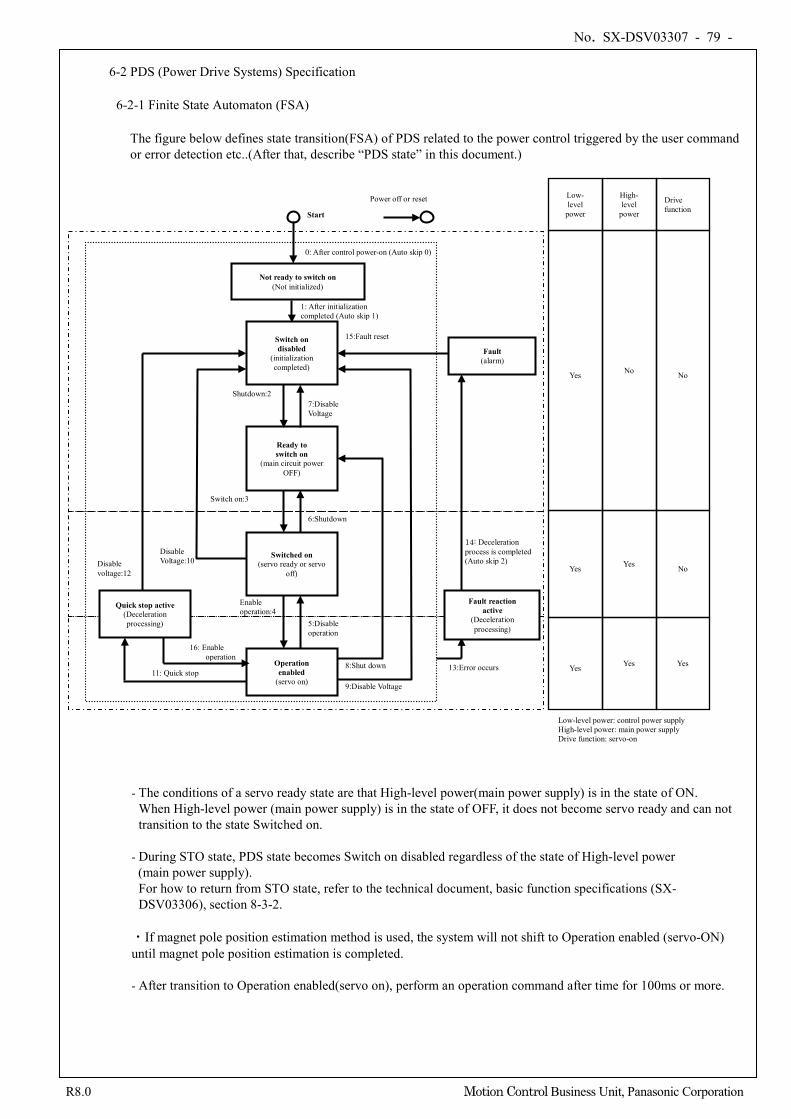
No. SX-DSV03307 - 79 -
R8.0 Motion Control Business Unit, Panasonic Corporation
6-2 PDS (Power Drive Systems) Specification
6-2-1 Finite State Automaton (FSA)
The figure below defines state transition(FSA) of PDS related to the power control triggered by the user command or error detection etc..(After that, describe “PDS state” in this document.)
- The conditions of a servo ready state are that High-level power(main power supply) is in the state of ON. When High-level power (main power supply) is in the state of OFF, it does not become servo ready and can not transition to the state Switched on.
- During STO state, PDS state becomes Switch on disabled regardless of the state of High-level power
(main power supply). For how to return from STO state, refer to the technical document, basic function specifications (SX-DSV03306), section 8-3-2.
・If magnet pole position estimation method is used, the system will not shift to Operation enabled (servo-ON) until magnet pole position estimation is completed. - After transition to Operation enabled(servo on), perform an operation command after time for 100ms or more.
Power off or reset
Not ready to switch on (Not initialized)
0: After control power-on (Auto skip 0)
1: After initialization completed (Auto skip 1)
Operation enabled
(servo on)
Switched on (servo ready or servo
off)
Enable operation:4
5:Disable operation
Fault (alarm)
14: Deceleration process is completed (Auto skip 2)
15:Fault reset
Ready to switch on
(main circuit power OFF)
13:Error occurs 8:Shut down
Switch on:3
6:Shutdown
Start
Switch on disabled
(initialization completed)
Shutdown:2 7:Disable Voltage
9:Disable Voltage
Disable Voltage:10
Quick stop active (Deceleration processing)
16: Enable operation
11: Quick stop
Disable voltage:12
Low-level power: control power supply High-level power: main power supply Drive function: servo-on
Yes
Yes
Yes
Yes
Yes
Yes
No
No
No
Low- level
power
High- level
power
Drive function
Fault reaction active
(Deceleration processing)
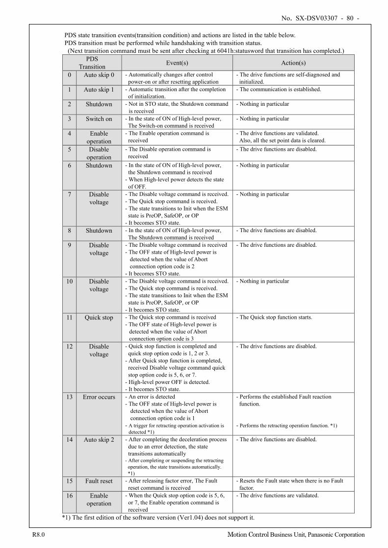
No. SX-DSV03307 - 80 -
R8.0 Motion Control Business Unit, Panasonic Corporation
PDS state transition events(transition condition) and actions are listed in the table below. PDS transition must be performed while handshaking with transition status. (Next transition command must be sent after checking at 6041h:statusword that transition has completed.)
PDS Transition Event(s) Action(s)
0 Auto skip 0 - Automatically changes after control power-on or after resetting application
- The drive functions are self-diagnosed and initialized.
1 Auto skip 1 - Automatic transition after the completion of initialization.
- The communication is established.
2 Shutdown - Not in STO state, the Shutdown command is received
- Nothing in particular
3 Switch on - In the state of ON of High-level power, The Switch-on command is received
- Nothing in particular
4 Enable operation
- The Enable operation command is received
- The drive functions are validated. Also, all the set point data is cleared.
5 Disable operation
- The Disable operation command is received
- The drive functions are disabled.
6 Shutdown - In the state of ON of High-level power, the Shutdown command is received
- When High-level power detects the state of OFF.
- Nothing in particular
7 Disable voltage
- The Disable voltage command is received. - The Quick stop command is received. - The state transitions to Init when the ESM
state is PreOP, SafeOP, or OP - It becomes STO state.
- Nothing in particular
8 Shutdown - In the state of ON of High-level power, The Shutdown command is received
- The drive functions are disabled.
9 Disable voltage
- The Disable voltage command is received - The OFF state of High-level power is
detected when the value of Abort connection option code is 2
- It becomes STO state.
- The drive functions are disabled.
10 Disable voltage
- The Disable voltage command is received. - The Quick stop command is received. - The state transitions to Init when the ESM
state is PreOP, SafeOP, or OP - It becomes STO state.
- Nothing in particular
11 Quick stop - The Quick stop command is received - The OFF state of High-level power is
detected when the value of Abort connection option code is 3
- The Quick stop function starts.
12 Disable voltage
- Quick stop function is completed and quick stop option code is 1, 2 or 3.
- After Quick stop function is completed, received Disable voltage command quick stop option code is 5, 6, or 7.
- High-level power OFF is detected. - It becomes STO state.
- The drive functions are disabled.
13 Error occurs - An error is detected - The OFF state of High-level power is
detected when the value of Abort connection option code is 1
- A trigger for retracting operation activation is detected *1)
- Performs the established Fault reaction function.
- Performs the retracting operation function. *1)
14 Auto skip 2 - After completing the deceleration process due to an error detection, the state transitions automatically
- After completing or suspending the retracting operation, the state transitions automatically. *1)
- The drive functions are disabled.
15 Fault reset - After releasing factor error, The Fault reset command is received
- Resets the Fault state when there is no Fault factor.
16 Enable operation
- When the Quick stop option code is 5, 6, or 7, the Enable operation command is received
- The drive functions are validated.
*1) The first edition of the software version (Ver1.04) does not support it.
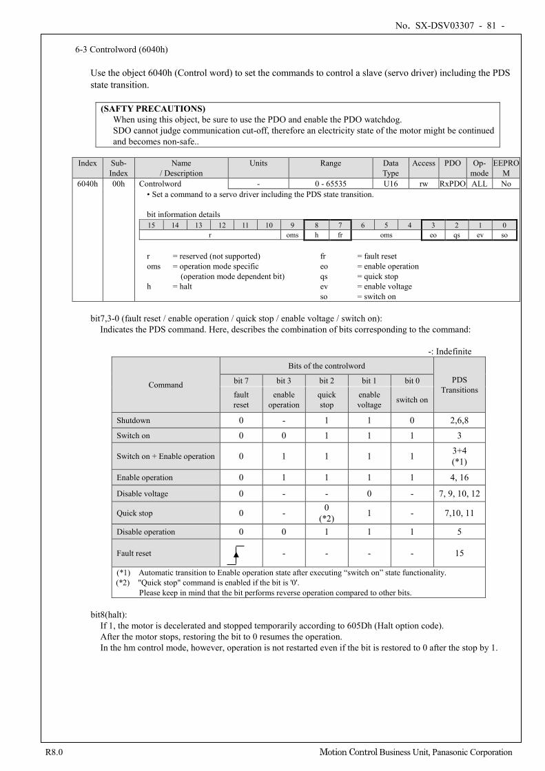
No. SX-DSV03307 - 81 -
R8.0 Motion Control Business Unit, Panasonic Corporation
6-3 Controlword (6040h)
Use the object 6040h (Control word) to set the commands to control a slave (servo driver) including the PDS state transition.
(SAFTY PRECAUTIONS) When using this object, be sure to use the PDO and enable the PDO watchdog. SDO cannot judge communication cut-off, therefore an electricity state of the motor might be continued and becomes non-safe..
Index Sub-
Index Name
/ Description Units Range Data
Type Access PDO Op-
mode EEPRO
M 6040h 00h Controlword - 0 - 65535 U16 rw RxPDO ALL No
• Set a command to a servo driver including the PDS state transition. bit information details 15 14 13 12 11 10 9 8 7 6 5 4 3 2 1 0
r oms h fr oms eo qs ev so
r = reserved (not supported) fr = fault reset oms = operation mode specific eo = enable operation
(operation mode dependent bit) qs = quick stop h = halt ev = enable voltage so = switch on
bit7,3-0 (fault reset / enable operation / quick stop / enable voltage / switch on):
Indicates the PDS command. Here, describes the combination of bits corresponding to the command:
-: Indefinite
Command
Bits of the controlword
PDS Transitions
bit 7 bit 3 bit 2 bit 1 bit 0
fault reset
enable operation
quick stop
enable voltage switch on
Shutdown 0 - 1 1 0 2,6,8 Switch on 0 0 1 1 1 3
Switch on + Enable operation 0 1 1 1 1 3+4 (*1)
Enable operation 0 1 1 1 1 4, 16
Disable voltage 0 - - 0 - 7, 9, 10, 12
Quick stop 0 - 0 (*2) 1 - 7,10, 11
Disable operation 0 0 1 1 1 5
Fault reset - - - - 15
(*1) Automatic transition to Enable operation state after executing “switch on” state functionality. (*2) "Quick stop" command is enabled if the bit is '0'.
Please keep in mind that the bit performs reverse operation compared to other bits.
bit8(halt): If 1, the motor is decelerated and stopped temporarily according to 605Dh (Halt option code). After the motor stops, restoring the bit to 0 resumes the operation. In the hm control mode, however, operation is not restarted even if the bit is restored to 0 after the stop by 1.
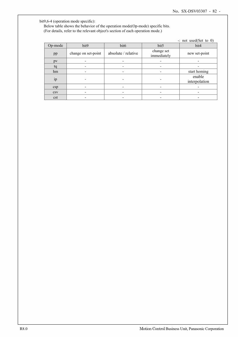
No. SX-DSV03307 - 82 -
R8.0 Motion Control Business Unit, Panasonic Corporation
bit9,6-4 (operation mode specific):
Below table shows the behavior of the operation mode(Op-mode) specific bits. (For details, refer to the relevant object's section of each operation mode.)
-: not used(Set to 0)
Op-mode bit9 bit6 bit5 bit4
pp change on set-point absolute / relative change set immediately new set-point
pv - - - - tq - - - - hm - - - start homing
ip - - - enable interpolation
csp - - - - csv - - - - cst - - - -
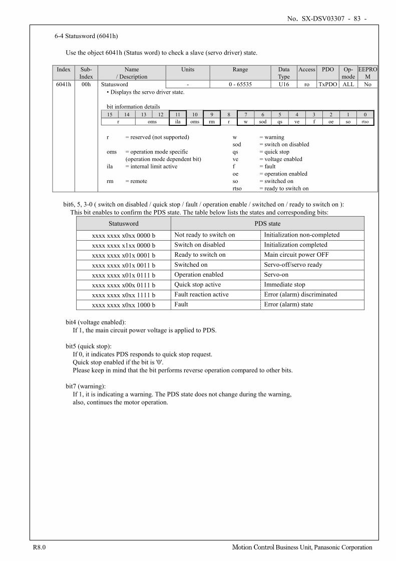
No. SX-DSV03307 - 83 -
R8.0 Motion Control Business Unit, Panasonic Corporation
6-4 Statusword (6041h)
Use the object 6041h (Status word) to check a slave (servo driver) state.
Index Sub-
Index Name
/ Description Units Range Data
Type Access PDO Op-
mode EEPRO
M 6041h 00h Statusword - 0 - 65535 U16 ro TxPDO ALL No
• Displays the servo driver state. bit information details 15 14 13 12 11 10 9 8 7 6 5 4 3 2 1 0
r oms ila oms rm r w sod qs ve f oe so rtso
r = reserved (not supported) w = warning sod = switch on disabled oms = operation mode specific qs = quick stop (operation mode dependent bit) ve = voltage enabled ila = internal limit active f = fault oe = operation enabled rm = remote so = switched on
rtso = ready to switch on
bit6, 5, 3-0 ( switch on disabled / quick stop / fault / operation enable / switched on / ready to switch on ): This bit enables to confirm the PDS state. The table below lists the states and corresponding bits:
Statusword PDS state
xxxx xxxx x0xx 0000 b Not ready to switch on Initialization non-completed xxxx xxxx x1xx 0000 b Switch on disabled Initialization completed xxxx xxxx x01x 0001 b Ready to switch on Main circuit power OFF xxxx xxxx x01x 0011 b Switched on Servo-off/servo ready xxxx xxxx x01x 0111 b Operation enabled Servo-on xxxx xxxx x00x 0111 b Quick stop active Immediate stop xxxx xxxx x0xx 1111 b Fault reaction active Error (alarm) discriminated xxxx xxxx x0xx 1000 b Fault Error (alarm) state
bit4 (voltage enabled):
If 1, the main circuit power voltage is applied to PDS. bit5 (quick stop):
If 0, it indicates PDS responds to quick stop request. Quick stop enabled if the bit is '0'. Please keep in mind that the bit performs reverse operation compared to other bits.
bit7 (warning): If 1, it is indicating a warning. The PDS state does not change during the warning, also, continues the motor operation.
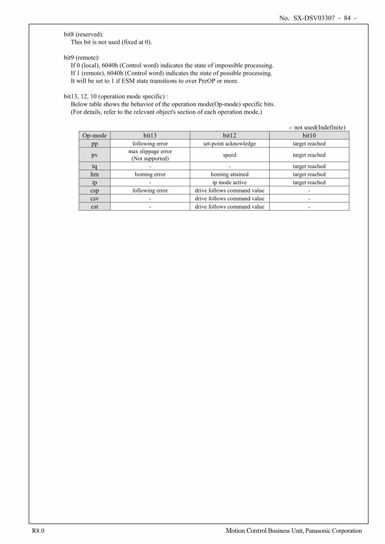
No. SX-DSV03307 - 84 -
R8.0 Motion Control Business Unit, Panasonic Corporation
bit8 (reserved):
This bit is not used (fixed at 0).
bit9 (remote): If 0 (local), 6040h (Control word) indicates the state of impossible processing. If 1 (remote), 6040h (Control word) indicates the state of possible processing. It will be set to 1 if ESM state transitions to over PreOP or more.
bit13, 12, 10 (operation mode specific) : Below table shows the behavior of the operation mode(Op-mode) specific bits. (For details, refer to the relevant object's section of each operation mode.)
-: not used(Indefinite)
Op-mode bit13 bit12 bit10 pp following error set-point acknowledge target reached
pv max slippage error (Not supported) speed target reached
tq - - target reached hm homing error homing attained target reached ip - ip mode active target reached
csp following error drive follows command value - csv - drive follows command value - cst - drive follows command value -
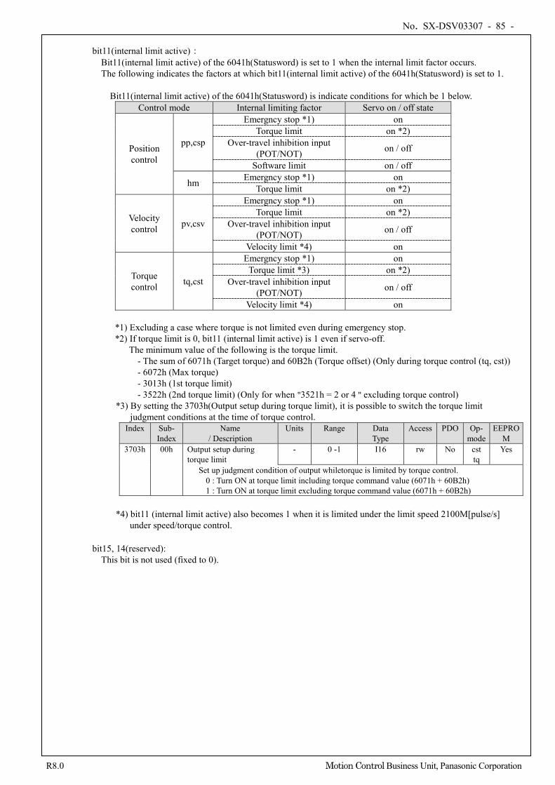
No. SX-DSV03307 - 85 -
R8.0 Motion Control Business Unit, Panasonic Corporation
bit11(internal limit active):
Bit11(internal limit active) of the 6041h(Statusword) is set to 1 when the internal limit factor occurs. The following indicates the factors at which bit11(internal limit active) of the 6041h(Statusword) is set to 1.
Bit11(internal limit active) of the 6041h(Statusword) is indicate conditions for which be 1 below. Control mode Internal limiting factor Servo on / off state
Position control
pp,csp
Emergncy stop *1) on Torque limit on *2)
Over-travel inhibition input (POT/NOT) on / off
Software limit on / off
hm Emergncy stop *1) on Torque limit on *2)
Velocity control pv,csv
Emergncy stop *1) on Torque limit on *2)
Over-travel inhibition input (POT/NOT) on / off
Velocity limit *4) on
Torque control tq,cst
Emergncy stop *1) on Torque limit *3) on *2)
Over-travel inhibition input (POT/NOT) on / off
Velocity limit *4) on
*1) Excluding a case where torque is not limited even during emergency stop. *2) If torque limit is 0, bit11 (internal limit active) is 1 even if servo-off.
The minimum value of the following is the torque limit. - The sum of 6071h (Target torque) and 60B2h (Torque offset) (Only during torque control (tq, cst)) - 6072h (Max torque) - 3013h (1st torque limit) - 3522h (2nd torque limit) (Only for when "3521h = 2 or 4 " excluding torque control)
*3) By setting the 3703h(Output setup during torque limit), it is possible to switch the torque limit judgment conditions at the time of torque control. Index Sub-
Index Name
/ Description Units Range Data
Type Access PDO Op-
mode EEPRO
M 3703h 00h Output setup during
torque limit - 0 -1 I16 rw No cst
tq Yes
Set up judgment condition of output whiletorque is limited by torque control. 0 : Turn ON at torque limit including torque command value (6071h + 60B2h) 1 : Turn ON at torque limit excluding torque command value (6071h + 60B2h)
*4) bit11 (internal limit active) also becomes 1 when it is limited under the limit speed 2100M[pulse/s]
under speed/torque control.
bit15, 14(reserved): This bit is not used (fixed to 0).
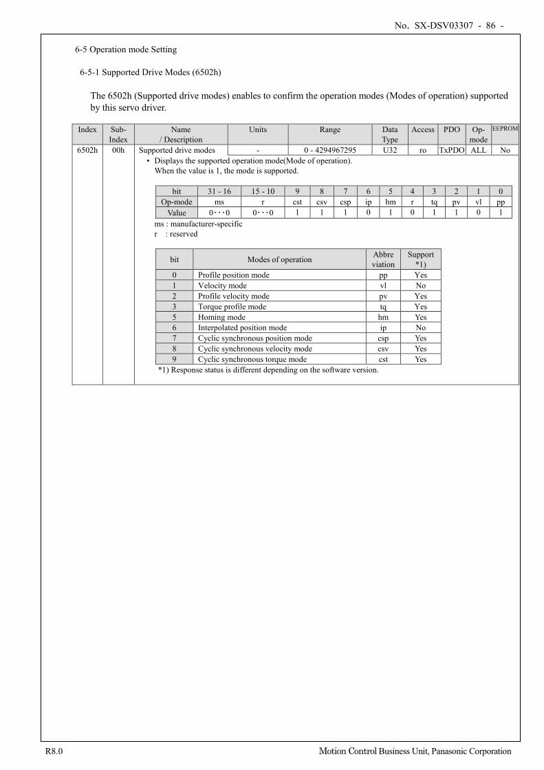
No. SX-DSV03307 - 86 -
R8.0 Motion Control Business Unit, Panasonic Corporation
6-5 Operation mode Setting
6-5-1 Supported Drive Modes (6502h)
The 6502h (Supported drive modes) enables to confirm the operation modes (Modes of operation) supported by this servo driver.
Index Sub-
Index Name
/ Description Units Range Data
Type Access PDO Op-
mode EEPROM
6502h 00h Supported drive modes - 0 - 4294967295 U32 ro TxPDO ALL No • Displays the supported operation mode(Mode of operation).
When the value is 1, the mode is supported.
bit 31 - 16 15 - 10 9 8 7 6 5 4 3 2 1 0 Op-mode ms r cst csv csp ip hm r tq pv vl pp
Value 0・・・0 0・・・0 1 1 1 0 1 0 1 1 0 1 ms : manufacturer-specific r : reserved
bit Modes of operation Abbreviation
Support *1)
0 Profile position mode pp Yes 1 Velocity mode vl No 2 Profile velocity mode pv Yes 3 Torque profile mode tq Yes 5 Homing mode hm Yes 6 Interpolated position mode ip No 7 Cyclic synchronous position mode csp Yes 8 Cyclic synchronous velocity mode csv Yes 9 Cyclic synchronous torque mode cst Yes
*1) Response status is different depending on the software version.
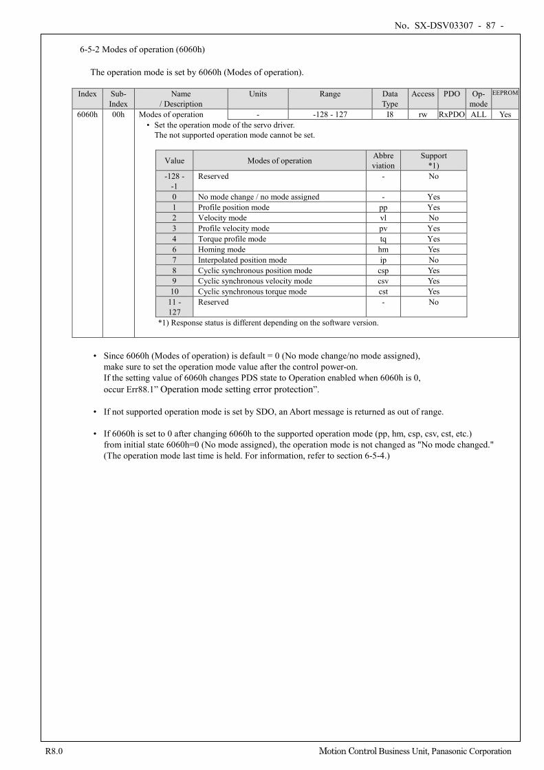
No. SX-DSV03307 - 87 -
R8.0 Motion Control Business Unit, Panasonic Corporation
6-5-2 Modes of operation (6060h)
The operation mode is set by 6060h (Modes of operation).
Index Sub-
Index Name
/ Description Units Range Data
Type Access PDO Op-
mode EEPROM
6060h 00h Modes of operation - -128 - 127 I8 rw RxPDO ALL Yes • Set the operation mode of the servo driver.
The not supported operation mode cannot be set.
Value Modes of operation Abbreviation
Support *1)
-128 - -1
Reserved - No
0 No mode change / no mode assigned - Yes 1 Profile position mode pp Yes 2 Velocity mode vl No 3 Profile velocity mode pv Yes 4 Torque profile mode tq Yes 6 Homing mode hm Yes 7 Interpolated position mode ip No 8 Cyclic synchronous position mode csp Yes 9 Cyclic synchronous velocity mode csv Yes 10 Cyclic synchronous torque mode cst Yes
11 - 127
Reserved - No
*1) Response status is different depending on the software version.
• Since 6060h (Modes of operation) is default = 0 (No mode change/no mode assigned),
make sure to set the operation mode value after the control power-on. If the setting value of 6060h changes PDS state to Operation enabled when 6060h is 0, occur Err88.1” Operation mode setting error protection”.
• If not supported operation mode is set by SDO, an Abort message is returned as out of range. • If 6060h is set to 0 after changing 6060h to the supported operation mode (pp, hm, csp, csv, cst, etc.)
from initial state 6060h=0 (No mode assigned), the operation mode is not changed as "No mode changed." (The operation mode last time is held. For information, refer to section 6-5-4.)
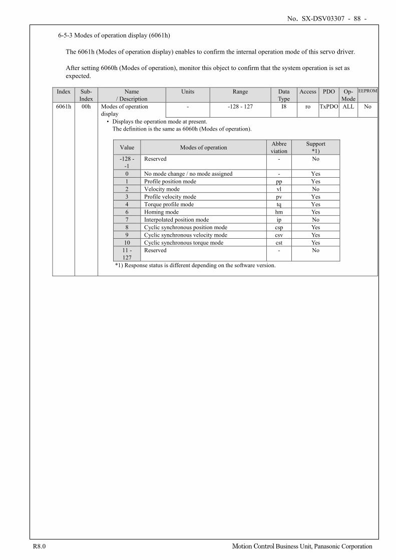
No. SX-DSV03307 - 88 -
R8.0 Motion Control Business Unit, Panasonic Corporation
6-5-3 Modes of operation display (6061h)
The 6061h (Modes of operation display) enables to confirm the internal operation mode of this servo driver. After setting 6060h (Modes of operation), monitor this object to confirm that the system operation is set as expected.
Index Sub-
Index Name
/ Description Units Range Data
Type Access PDO Op-
Mode EEPROM
6061h 00h Modes of operation display
- -128 - 127 I8 ro TxPDO ALL No
• Displays the operation mode at present. The definition is the same as 6060h (Modes of operation).
Value Modes of operation Abbreviation
Support *1)
-128 - -1
Reserved - No
0 No mode change / no mode assigned - Yes 1 Profile position mode pp Yes 2 Velocity mode vl No 3 Profile velocity mode pv Yes 4 Torque profile mode tq Yes 6 Homing mode hm Yes 7 Interpolated position mode ip No 8 Cyclic synchronous position mode csp Yes 9 Cyclic synchronous velocity mode csv Yes 10 Cyclic synchronous torque mode cst Yes
11 - 127
Reserved - No
*1) Response status is different depending on the software version.
No. SX-DSV03307 - 89 -
R8.0 Motion Control Business Unit, Panasonic Corporation
6-5-4 Caution for Changing Operation mode
• The operation mode can be switched by changing the value of 6060h (Modes of operation).
• The 6061h (Modes of operation display) enables to confirm the operation mode of the servo driver at present.
• When changing the operation mode, synchronize 6060h and the RxPDO objects related to operation mode and
then update.
• The values of objects that are not supported by the changed operation mode are irregular.
• About 2 ms is required from the time when the operation mode is changed until the completion of the change. During this time, the value of 6061h and the value of the object of TxPDO related to the operation mode are irregular.
• The MINAS-A6BL series do not support changing the control mode during operation.
When changing the operation mode, make sure that the motor is stopped. If the control mode is changed during a motor operation (including during an origin return operation and
deceleration stop), the operation cannot be guaranteed. The mode may not be changed immediately or Err27.4 (command error protection 1) etc. may occur.
• When 6060h and 6061h are 0 and PDS state is made to change to "Operation enabled",
Err88.1(Operation mode setting error protection) occurs. • Set the values other than 0 to 6060h(Modes of operation) once, when set as 6060h=0 after that,
the last operation mode is held. • If a not supported operation mode is set to 6060h, Err88.1 (Operation mode setting error protection) occurs.
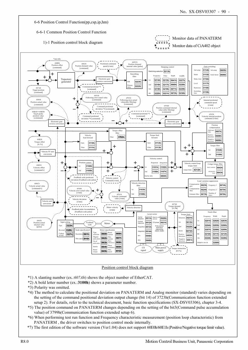
No. SX-DSV03307 - 90 -
R8.0 Motion Control Business Unit, Panasonic Corporation
6-6 Position Control Function(pp,csp,ip,hm)
6-6-1 Common Position Control Function
1)-1 Position control block diagram
+
-
+
+
+
-
Velocity detection
6074h Torque demand
[0.1%]
60F4h Following error actual value
[command]
+ +
+
+
6063h Position actual internal value
[pulse]
Feedback scale Motor
6064h Position actual value
[command]
60BAh~60BDh Touch probe
position value [command]
Trajectory generator
60B1h Velocity offset [command/s]
+ +
60FCh Position demand
internal value [pulse]
60B2h Torque offset
[0.1%]
6062h Position demand value
[command]
-
+
607Ah Target position
[command]
Command positional *5 [command]
Feedback scale positional deviation [Feedback scale pulse]
Motor velocity [r/min]
+ +
60B0h Position offset
[command]
*csp only
Command positional deviation *4 [command]
Feedback pulse Accumulation [Feedback scale pulse]
- +
606Ch Velocity actual value
[command/s]
4F01h Following error actual value(after filtering)
[command] 4F04h
Position command internal value (after filtering)
[command] 4FA5h
Velocity internal position command [r/min]
-
+
Velocity deviation [r/min]
4FA6h Velocity error actual value
[r/min] 4FA1h
Velocity command value [r/min]
Electronic gear positive conversion
Electronic gear reverse conversion
Electronic gear reverse conversion
Smoothing filter
FIR 3223h Primary delay 3222h
Positional command speed [r/min] Damping control
1st 3214h
2nd 3216h
3rd 3218h
3215h
3217h
3219h
4th 3220h 3221h
Switching selection 3213h
Frequency Filter
3641h
Depth
3660h
3671h
3672h
width
3227h
3228h
3229h
3230h
Command positional deviation *4 [command]
Command positional *5 [command]
Gain switching
2nd setup 3114h
Mode 3115h
Delay time 3116h
Level 3117h
Hysteresis 3118h Switching time 3119h
3rd setup 3605h
Scale factor 3606h
Internal positional command speed
[r/min]
Velocity feed forward
Gain 3110h
Filter 3111h
Velocity FF unit conversion
Velocity unit conversion
Position control
1st 3100h
2nd 3105h
Velocity control Command [r/min]
Torque feed forward
Gain 3112h
Filter 3113h
Velocity detection filter
1st 3103h
2nd 3108h
Velocity control
3102h
3107h
Proportion Integration
Inertia ratio
1st 3101h
2nd 3106h
3004h
Friction compensation
Additional value 3607h Positive direction 3608h Negative direction 3609h
Torque filter
1st 3104h
2nd 3109h
2-stage torque filter
3642h
3643h
time constant
attenuation term
Load variation suppression
Compensation gain 3623h Compensation filter 3624h
Estimate filter 3673h
Frequency 1 3674h
Frequency 2 3675h Number of times 3676h
Notch filter
3203h
3206h
3209h
3212h
Depth
3202h
3205h
3208h
3211h
Width
1st 3201h
2nd 3204h 3rd 3207h
4th 3210h
Frequency
Adaptive mo de 3200h
5th 3226h 3225h 3224h
Torque instruction [0.1%]
Velocity control loop torque limit
torque limit 4312h
Torque offset filter
Filter 37B3h
+
Input setting
3326h Reversal
Type 3323h
Z phase invalid 3327h
Scale specification
Resolution 3901h Max.speed 3910h
Motor specification
Magnet pole pitch No.of pole pairs
Type selection
Inertia
Rated torque
Rated current Max. current
Max. speed
Phase inductance
Phase resistance
3900h 3902h 3903h 3904h 3905h
3906h 3907h 3908h 3909h 3910h
Torque limit
Selection 3521h
MAX 6072h
1st 3013h
2nd 3522h
Positive direction 60E0h Negative direction 60E1h
CS signal
Main power supply
Current control
Current response 3912h
Proportion 3913h
Carrier selection 3911h
Integration 3914h
Magnetic pole detected 3920h
CS phase 3921h
Pole position estimation relationship
3922h–3928h
FF1 3948h
FF2 3949h
Position control block diagram
*1) A slanting number (ex.:607Ah) shows the object number of EtherCAT. *2) A bold letter number (ex.:3100h) shows a parameter number. *3) Polarity was omitted. *4) The method to calculate the positional deviation on PANATERM and Analog monitor (standard) varies depending on
the setting of the command positional deviation output change (bit 14) of 3723h(Communication function extended setup 2). For details, refer to the technical document, basic function specifications (SX-DSV03306), chapter 3-4.
*5) The position command on PANATERM changes depending on the setting of the bit3(Command pulse accumulation value) of 3799h(Communication function extended setup 6). *6) When performing test run function and Frequency characteristic measurement (position loop characteristic) from
PANATERM , the driver switches to position control mode internally. *7) The first edition of the software version (Ver1.04) does not support 60E0h/60E1h (Positive/Negative torque limit value).
Monitor data of PANATERM
Monitor data of CiA402 object
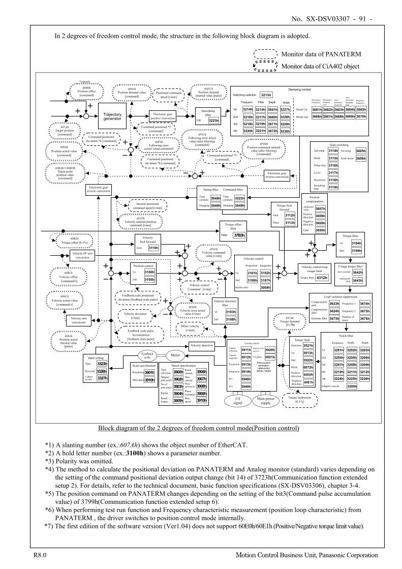
No. SX-DSV03307 - 91 -
R8.0 Motion Control Business Unit, Panasonic Corporation
In 2 degrees of freedom control mode, the structure in the following block diagram is adopted.
+
-
+
+ + -
Velocity detection
6074h Torque demand
[0.1%]
60F4h Following error
actual value[command]
+
+
+
+
6063h Position actual internal value
[pulse]
6064h Position actual value
[command]
60BAh~60BDh Touch probe
position value [command]
Trajectory generator
606Ch Velocity actual value
[command/s]
60B1h Velocity offset [command/s]
+ +
60FCh Position demand
internal value [pulse]
60B2h Torque offset [0.1%]
6062h Position demand value
[command]
-
+
607Ah Target position
[command]
Velocity control Command [r/min]
+ +
60B0h Position offset
[command]
*csponly
Torque instruction [0.1%]
- +
4FA5h Velocity internal position
command [r/min]
4F04h Position command internal
value (after filtering) [command]
4F01h Following error actual value (after filtering)
[command]
4FA1h Velocity command
value [r/min]
+
- 4FA6h
Velocity error actual value [r/min]
Internal positional command speed [r/min]
Positional command speed [r/min]
Command positional *5 [command]
Command positional deviation *4 [command]
Command positional deviation *4 [command]
Command positional *5 [command]
Electronic gear positive conversion
Electronic gear reverse conversion
Electronic gear reverse conversion
Smoothing filter
FIR 3223h
Damping control
1st 3214h
2nd 3216h
Depth
3641h 3215h
3217h
Switching selection 3213h
Frequenc
Filter
3660h
3rd
4th
3661h 3662h 3663h 3664h 3665h
3666h 3667h 3668h 3669h 3670h
Model 1st
3218h 3219h 3671h
3220h 3221h 3672h
Model 2nd
Width
3227h
3228h
3229h
3230h
Resonance damping ratio
Anti- resonance frequency
Anti- resonance damping ratio
Response frequency
Resonance Frequency
Gain switching
2nd setup 3114h
Mode 3115h
Delay time 3116h
Level 3117h
Hysteresis 3118h Switching time 3119h
3rd setup 3605h
Scale factor 3606h
Tuning filter Command filter
Time constant 3648h
Damping 3649h
Time constant 3222h
Damping 3649h Torque feed forward
Gain 3112h
Filter 3113h
Friction compensation
Additional value 3607h Positive direction 3608h Negative direction 3609h
Gain 3650h Torque filter
1st 3104h
2nd 3109h
2-stage torque filter
3642h
3643h
time constant
attenuation term
Velocity control
3102h
3107h
Proportion Integration
Inertia ratio
1st 3101h
2nd 3106h
3004h
Velocity feed forward
Gain 3110h Velocity FF unit
conversion
Velocity unit conversion
Position control
1st 3100h
2nd 3105h
Velocity detection filter
1st 3103h
2nd 3108h
Load variation suppression
Compensation gain 3623h Compensation filter 3624h
Estimate filter 3673h
Frequency 1 3674h
Frequency 2 3675h Number of times 3676h
Notch filter
3203h
3206h
3209h
3212h
Depth
3202h
3205h
3208h
3211h
Width
1st 3201h
2nd 3204h 3rd 3207h
4th 3210h
Frequency
Adaptive mo de 3200h
5th 3226h 3225h 3224h
Feedback scale positional deviation [feedback scale pulse]
l ]
Motor velocity [r/min] Feedback scale pulse
Accumulation [feedback scale pulse]
Velocity deviation [r/min]
Torque offset filter
Filter 37B3h
Velocity control loop torque limit
Torque limit 4312h
Input setting
3326h Reversal
Type 3323h
Z phase invalid 3327h
Feedback scale Motor
Scale specification
Resolution 3901h Max.speed 3910h
Motor specification
Magnet pole pitch No.of pole pairs
Type selection
Inertia
Rated torque
Rated current Max. current
Max. speed
Phase inductance
Phase resistance
3900h 3902h 3903h 3904h 3905h
3906h 3907h 3908h 3909h 3910h
Torque limit
Selection 3521h
MAX 6072h
1st 3013h
2nd 3522h
Positive direction 60E0h Negative direction 60E1h
CS signal
Main power supply
Current control
Current response 3912h
Proportion 3913h
Carrier selection 3911h
Integration 3914h
Magnetic pole detected 3920h
CS phase 3921h
Pole position estimation relationship
3922h–3928h
FF1 3948h
FF2 3949h
Block diagram of the 2 degrees of freedom control mode(Position control)
*1) A slanting number (ex.:607Ah) shows the object number of EtherCAT. *2) A bold letter number (ex.:3100h) shows a parameter number. *3) Polarity was omitted. *4) The method to calculate the positional deviation on PANATERM and Analog monitor (standard) varies depending on
the setting of the command positional deviation output change (bit 14) of 3723h(Communication function extended setup 2). For details, refer to the technical document, basic function specifications (SX-DSV03306), chapter 3-4.
*5) The position command on PANATERM changes depending on the setting of the bit3(Command pulse accumulation value) of 3799h(Communication function extended setup 6). *6) When performing test run function and Frequency characteristic measurement (position loop characteristic) from
PANATERM , the driver switches to position control mode internally. *7) The first edition of the software version (Ver1.04) does not support 60E0h/60E1h (Positive/Negative torque limit value).
Monitor data of PANATERM
Monitor data of CiA402 object
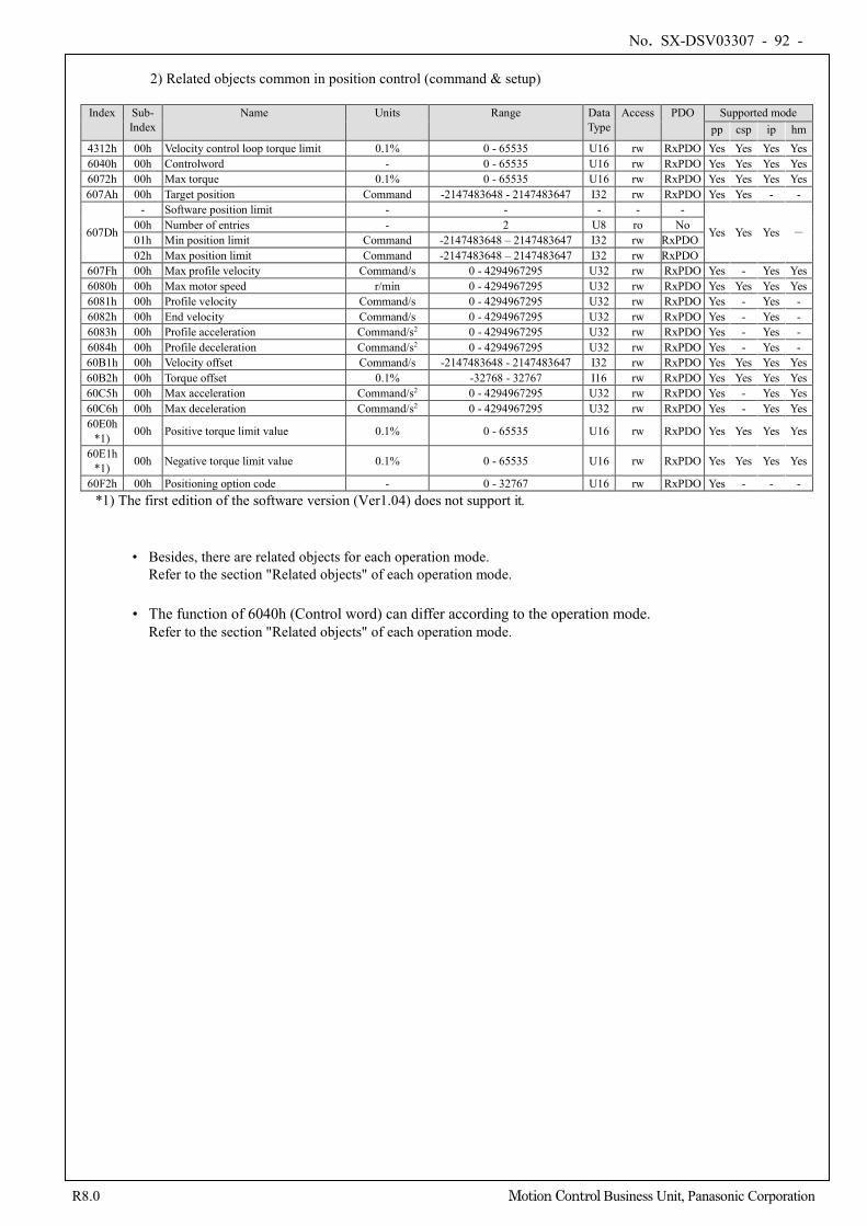
No. SX-DSV03307 - 92 -
R8.0 Motion Control Business Unit, Panasonic Corporation
2) Related objects common in position control (command & setup)
Index Sub-
Index Name Units Range Data
Type Access PDO Supported mode
pp csp ip hm 4312h 00h Velocity control loop torque limit 0.1% 0 - 65535 U16 rw RxPDO Yes Yes Yes Yes 6040h 00h Controlword - 0 - 65535 U16 rw RxPDO Yes Yes Yes Yes 6072h 00h Max torque 0.1% 0 - 65535 U16 rw RxPDO Yes Yes Yes Yes 607Ah 00h Target position Command -2147483648 - 2147483647 I32 rw RxPDO Yes Yes - -
607Dh
- Software position limit - - - - -
Yes Yes Yes - 00h Number of entries - 2 U8 ro No 01h Min position limit Command -2147483648 – 2147483647 I32 rw RxPDO 02h Max position limit Command -2147483648 – 2147483647 I32 rw RxPDO
607Fh 00h Max profile velocity Command/s 0 - 4294967295 U32 rw RxPDO Yes - Yes Yes 6080h 00h Max motor speed r/min 0 - 4294967295 U32 rw RxPDO Yes Yes Yes Yes 6081h 00h Profile velocity Command/s 0 - 4294967295 U32 rw RxPDO Yes - Yes - 6082h 00h End velocity Command/s 0 - 4294967295 U32 rw RxPDO Yes - Yes - 6083h 00h Profile acceleration Command/s2 0 - 4294967295 U32 rw RxPDO Yes - Yes - 6084h 00h Profile deceleration Command/s2 0 - 4294967295 U32 rw RxPDO Yes - Yes - 60B1h 00h Velocity offset Command/s -2147483648 - 2147483647 I32 rw RxPDO Yes Yes Yes Yes 60B2h 00h Torque offset 0.1% -32768 - 32767 I16 rw RxPDO Yes Yes Yes Yes 60C5h 00h Max acceleration Command/s2 0 - 4294967295 U32 rw RxPDO Yes - Yes Yes 60C6h 00h Max deceleration Command/s2 0 - 4294967295 U32 rw RxPDO Yes - Yes Yes 60E0h
*1) 00h Positive torque limit value 0.1% 0 - 65535 U16 rw RxPDO Yes Yes Yes Yes
60E1h *1) 00h Negative torque limit value 0.1% 0 - 65535 U16 rw RxPDO Yes Yes Yes Yes
60F2h 00h Positioning option code - 0 - 32767 U16 rw RxPDO Yes - - - *1) The first edition of the software version (Ver1.04) does not support it.
• Besides, there are related objects for each operation mode.
Refer to the section "Related objects" of each operation mode.
• The function of 6040h (Control word) can differ according to the operation mode. Refer to the section "Related objects" of each operation mode.
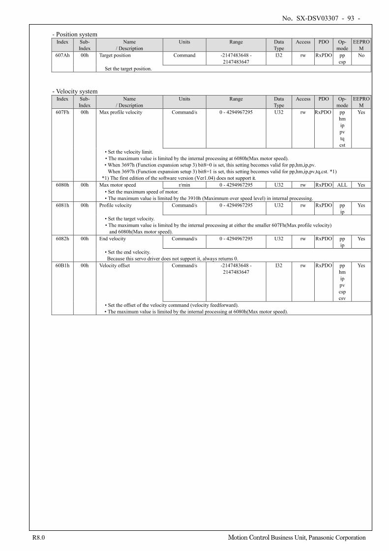
No. SX-DSV03307 - 93 -
R8.0 Motion Control Business Unit, Panasonic Corporation
- Position system
Index Sub- Index
Name / Description
Units Range Data Type
Access PDO Op- mode
EEPROM
607Ah 00h Target position Command -2147483648 - 2147483647
I32 rw RxPDO pp csp
No
Set the target position. - Velocity system
Index Sub- Index
Name / Description
Units Range Data Type
Access PDO Op- mode
EEPROM
607Fh 00h Max profile velocity Command/s 0 - 4294967295 U32 rw RxPDO pp hm ip pv tq cst
Yes
• Set the velocity limit. • The maximum value is limited by the internal processing at 6080h(Max motor speed). • When 3697h (Function expansion setup 3) bit8=0 is set, this setting becomes valid for pp,hm,ip,pv.
When 3697h (Function expansion setup 3) bit8=1 is set, this setting becomes valid for pp,hm,ip,pv,tq,cst. *1) *1) The first edition of the software version (Ver1.04) does not support it.
6080h 00h Max motor speed r/min 0 - 4294967295 U32 rw RxPDO ALL Yes • Set the maximum speed of motor. • The maximum value is limited by the 3910h (Maximnum over speed level) in internal processing.
6081h 00h Profile velocity Command/s 0 - 4294967295 U32 rw RxPDO pp ip
Yes
• Set the target velocity. • The maximum value is limited by the internal processing at either the smaller 607Fh(Max profile velocity)
and 6080h(Max motor speed). 6082h 00h End velocity Command/s 0 - 4294967295 U32 rw RxPDO pp
ip Yes
• Set the end velocity. Because this servo driver does not support it, always returns 0.
60B1h 00h Velocity offset Command/s -2147483648 - 2147483647
I32 rw RxPDO pp hm ip pv csp csv
Yes
• Set the offset of the velocity command (velocity feedforward). • The maximum value is limited by the internal processing at 6080h(Max motor speed).
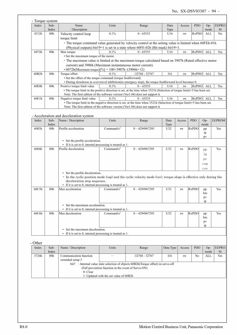
No. SX-DSV03307 - 94 -
R8.0 Motion Control Business Unit, Panasonic Corporation
- Torque system
Index Sub- Index
Name / Description
Units Range Data Type
Access PDO Op- mode
EEPROM
4312h 00h Velocity control loop torque limit
0.1% 0 - 65535 U16 rw RxPDO ALL No
・The torque command value generated by velocity control at the setting value is limited when 60FEh-01h (Physical outputs) bit19=1 is set in a state where 60FE-02h (Bit mask) bit19=1.
6072h 00h Max torque 0.1% 0 - 65535 U16 rw RxPDO ALL Yes • Set the maximum torque of the motor. ・The maximum value is limited at the maximum torque calculated based on 3907h (Rated effective motor
current) and 3906h (Maximum instantaneous motor current). • 6072h(Maximum torque)[%] = 100×3907h /(3906h×√2)
60B2h 00h Torque offset 0.1% -32768 - 32767 I16 rw RxPDO ALL Yes • Set the offset of the torque command (torque feedforward). • During slowdown in over-travel inhibition(in emergncy stop), the torque feedforward level becomes 0.
60E0h 00h Positive torque limit value 0.1% 0 – 65535 U16 rw RxPDO ALL Yes • The torque limit in the positive direction is set, at the time when 3521h (Selection of torque limit)=5 has been set. Note: The first edition of the software version (Ver1.04) does not support it.
60E1h 00h Negative torque limit value 0.1% 0 – 65535 U16 rw RxPDO ALL Yes • The torque limit in the negative direction is set, at the time when 3521h (Selection of torque limit)=5 has been set. Note: The first edition of the software version (Ver1.04) does not support it.
- Acceleration and deceleration system
Index Sub- Index
Name / Description Units Range Data Type
Access PDO Op- mode
EEPROM
6083h 00h Profile acceleration Command/s2 0 – 4294967295 U32 rw RxPDO pp ip pv
Yes
• Set the profile acceleration. • If it is set to 0, internal processing is treated as 1.
6084h 00h Profile deceleration Command/s2 0 – 4294967295 U32 rw RxPDO pp
ip
pv
csp
csv
Yes
• Set the profile deceleration. • In the cyclic position mode (csp) and the cyclic velocity mode (csv), torque slope is effective only during the
deceleration stop sequence. • If it is set to 0, internal processing is treated as 1.
60C5h 00h Max acceleration Command/s2 0 – 4294967295 U32 rw RxPDO pp hm pv ip
Yes
• Set the maximum acceleration. • If it is set to 0, internal processing is treated as 1.
60C6h 00h Max deceleration Command/s2 0 – 4294967295 U32 rw RxPDO pp hm pv ip
Yes
• Set the maximum deceleration. • If it is set to 0, internal processing is treated as 1.
- Other
Index Sub- Index
Name / Description Units Range Data Type Access PDO Op- mode
EEPROM
3724h 00h Communication function extended setup 3
- -32768 - 32767 I16 rw No ALL Yes
bit7 : Internal value state selection of objects 60B2h(Torque offset) in servo-off (Fall prevention function in the event of Servo-ON) 0: Clear 1: Updated with the set value of 60B2h
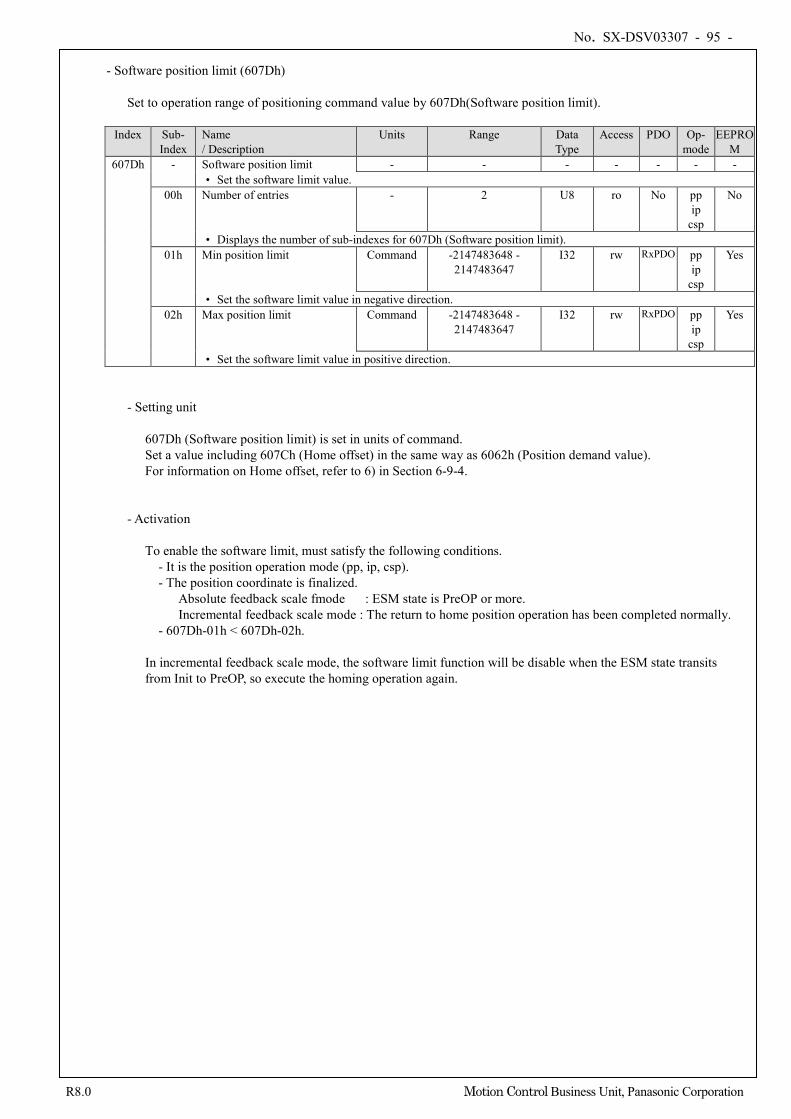
No. SX-DSV03307 - 95 -
R8.0 Motion Control Business Unit, Panasonic Corporation
- Software position limit (607Dh)
Set to operation range of positioning command value by 607Dh(Software position limit).
Index Sub- Index
Name / Description
Units Range Data Type
Access PDO Op- mode
EEPROM
607Dh - Software position limit - - - - - - - • Set the software limit value.
00h Number of entries - 2 U8 ro No pp ip
csp
No
• Displays the number of sub-indexes for 607Dh (Software position limit). 01h Min position limit Command -2147483648 -
2147483647 I32 rw RxPDO pp
ip csp
Yes
• Set the software limit value in negative direction. 02h Max position limit Command -2147483648 -
2147483647 I32 rw RxPDO pp
ip csp
Yes
• Set the software limit value in positive direction. - Setting unit
607Dh (Software position limit) is set in units of command. Set a value including 607Ch (Home offset) in the same way as 6062h (Position demand value). For information on Home offset, refer to 6) in Section 6-9-4.
- Activation
To enable the software limit, must satisfy the following conditions. - It is the position operation mode (pp, ip, csp). - The position coordinate is finalized.
Absolute feedback scale fmode : ESM state is PreOP or more. Incremental feedback scale mode : The return to home position operation has been completed normally.
- 607Dh-01h < 607Dh-02h. In incremental feedback scale mode, the software limit function will be disable when the ESM state transits from Init to PreOP, so execute the homing operation again.
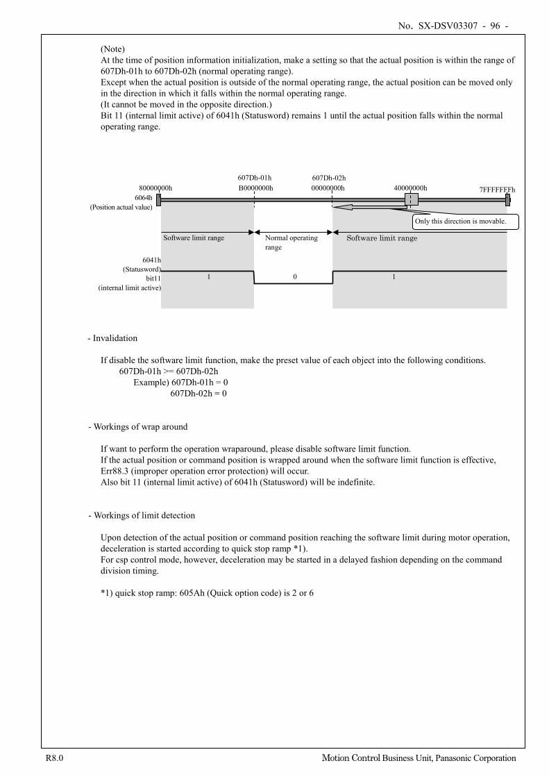
No. SX-DSV03307 - 96 -
R8.0 Motion Control Business Unit, Panasonic Corporation
(Note) At the time of position information initialization, make a setting so that the actual position is within the range of 607Dh-01h to 607Dh-02h (normal operating range). Except when the actual position is outside of the normal operating range, the actual position can be moved only in the direction in which it falls within the normal operating range. (It cannot be moved in the opposite direction.) Bit 11 (internal limit active) of 6041h (Statusword) remains 1 until the actual position falls within the normal operating range.
- Invalidation
If disable the software limit function, make the preset value of each object into the following conditions. 607Dh-01h >= 607Dh-02h
Example) 607Dh-01h = 0 607Dh-02h = 0
- Workings of wrap around
If want to perform the operation wraparound, please disable software limit function. If the actual position or command position is wrapped around when the software limit function is effective, Err88.3 (improper operation error protection) will occur. Also bit 11 (internal limit active) of 6041h (Statusword) will be indefinite.
- Workings of limit detection
Upon detection of the actual position or command position reaching the software limit during motor operation, deceleration is started according to quick stop ramp *1). For csp control mode, however, deceleration may be started in a delayed fashion depending on the command division timing. *1) quick stop ramp: 605Ah (Quick option code) is 2 or 6
6041h (Statusword)
bit11 (internal limit active)
1 0 1
Software limit range Normal operating range
Software limit range
607Dh-01h 607Dh-02h
Only this direction is movable.
80000000h 7FFFFFFFh B0000000h 40000000h 00000000h 6064h
(Position actual value)
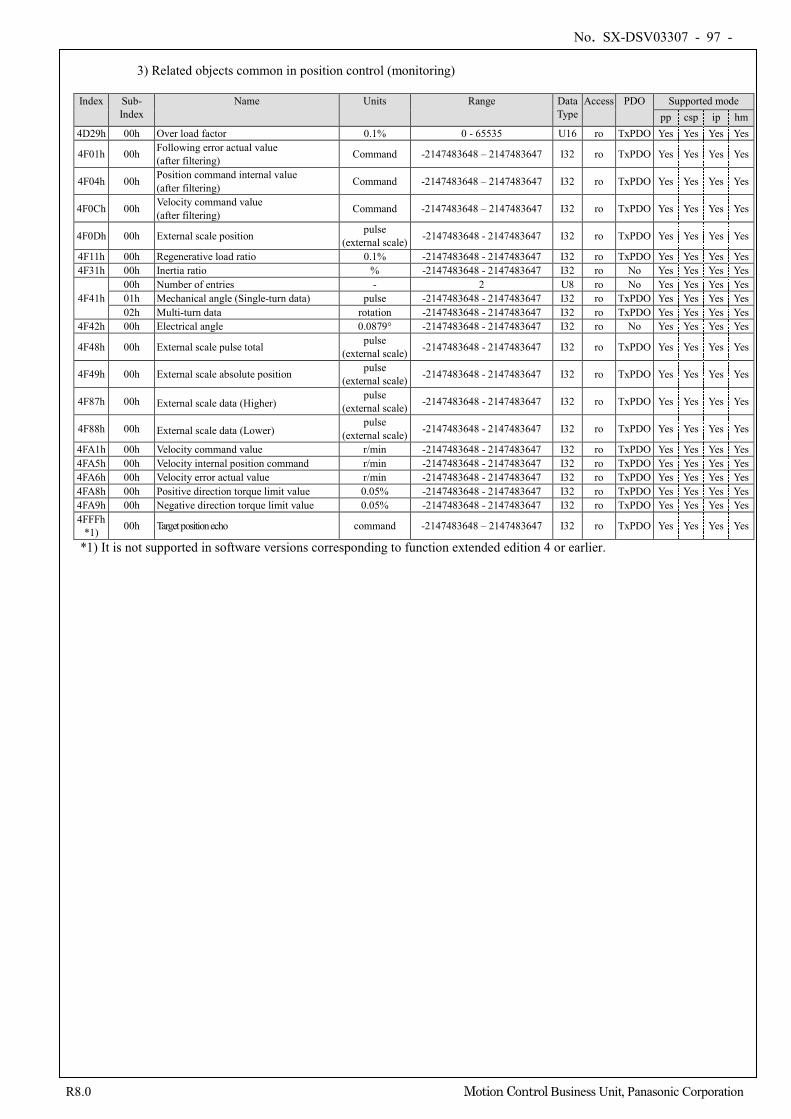
No. SX-DSV03307 - 97 -
R8.0 Motion Control Business Unit, Panasonic Corporation
3) Related objects common in position control (monitoring)
Index Sub-
Index Name Units Range Data
Type Access PDO Supported mode
pp csp ip hm 4D29h 00h Over load factor 0.1% 0 - 65535 U16 ro TxPDO Yes Yes Yes Yes
4F01h 00h Following error actual value (after filtering) Command -2147483648 – 2147483647 I32 ro TxPDO Yes Yes Yes Yes
4F04h 00h Position command internal value (after filtering) Command -2147483648 – 2147483647 I32 ro TxPDO Yes Yes Yes Yes
4F0Ch 00h Velocity command value (after filtering) Command -2147483648 – 2147483647 I32 ro TxPDO Yes Yes Yes Yes
4F0Dh 00h External scale position pulse (external scale) -2147483648 - 2147483647 I32 ro TxPDO Yes Yes Yes Yes
4F11h 00h Regenerative load ratio 0.1% -2147483648 - 2147483647 I32 ro TxPDO Yes Yes Yes Yes 4F31h 00h Inertia ratio % -2147483648 - 2147483647 I32 ro No Yes Yes Yes Yes
4F41h 00h Number of entries - 2 U8 ro No Yes Yes Yes Yes 01h Mechanical angle (Single-turn data) pulse -2147483648 - 2147483647 I32 ro TxPDO Yes Yes Yes Yes 02h Multi-turn data rotation -2147483648 - 2147483647 I32 ro TxPDO Yes Yes Yes Yes
4F42h 00h Electrical angle 0.0879° -2147483648 - 2147483647 I32 ro No Yes Yes Yes Yes
4F48h 00h External scale pulse total pulse (external scale) -2147483648 - 2147483647 I32 ro TxPDO Yes Yes Yes Yes
4F49h 00h External scale absolute position pulse (external scale) -2147483648 - 2147483647 I32 ro TxPDO Yes Yes Yes Yes
4F87h 00h External scale data (Higher) pulse
(external scale) -2147483648 - 2147483647 I32 ro TxPDO Yes Yes Yes Yes
4F88h 00h External scale data (Lower) pulse
(external scale) -2147483648 - 2147483647 I32 ro TxPDO Yes Yes Yes Yes
4FA1h 00h Velocity command value r/min -2147483648 - 2147483647 I32 ro TxPDO Yes Yes Yes Yes 4FA5h 00h Velocity internal position command r/min -2147483648 - 2147483647 I32 ro TxPDO Yes Yes Yes Yes 4FA6h 00h Velocity error actual value r/min -2147483648 - 2147483647 I32 ro TxPDO Yes Yes Yes Yes 4FA8h 00h Positive direction torque limit value 0.05% -2147483648 - 2147483647 I32 ro TxPDO Yes Yes Yes Yes 4FA9h 00h Negative direction torque limit value 0.05% -2147483648 - 2147483647 I32 ro TxPDO Yes Yes Yes Yes 4FFFh
*1) 00h Target position echo command -2147483648 – 2147483647 I32 ro TxPDO Yes Yes Yes Yes
*1) It is not supported in software versions corresponding to function extended edition 4 or earlier.
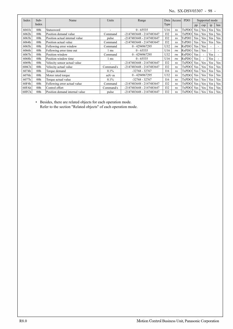
No. SX-DSV03307 - 98 -
R8.0 Motion Control Business Unit, Panasonic Corporation
Index Sub- Index
Name Units Range Data Type
Access PDO Supported mode pp csp ip hm
6041h 00h Statusword - 0 - 65535 U16 ro TxPDO Yes Yes Yes Yes 6062h 00h Position demand value Command -2147483648 - 2147483647 I32 ro TxPDO Yes Yes Yes Yes 6063h 00h Position actual internal value pulse -2147483648 - 2147483647 I32 ro TxPDO Yes Yes Yes Yes 6064h 00h Position actual value Command -2147483648 - 2147483647 I32 ro TxPDO Yes Yes Yes Yes 6065h 00h Following error window Command 0 - 4294967295 U32 rw RxPDO Yes Yes - - 6066h 00h Following error time out 1 ms 0 - 65535 U16 rw RxPDO Yes Yes - - 6067h 00h Position window Command 0 - 4294967295 U32 rw RxPDO Yes - Yes - 6068h 00h Position window time 1 ms 0 - 65535 U16 rw RxPDO Yes - Yes - 6069h 00h Velocity sensor actual value - -2147483648 - 2147483647 I32 ro TxPDO Yes Yes Yes Yes 606Ch 00h Velocity actual value Command/s -2147483648 - 2147483647 I32 ro TxPDO Yes Yes Yes Yes 6074h 00h Torque demand 0.1% -32768 - 32767 I16 ro TxPDO Yes Yes Yes Yes 6076h 00h Motor rated torque mN・m 0 - 4294967295 U32 ro TxPDO Yes Yes Yes Yes 6077h 00h Torque actual value 0.1% -32768 - 32767 I16 ro TxPDO Yes Yes Yes Yes 60F4h 00h Following error actual value Command -2147483648 - 2147483647 I32 ro TxPDO Yes Yes Yes Yes 60FAh 00h Control effort Command/s -2147483648 - 2147483647 I32 ro TxPDO Yes Yes Yes Yes 60FCh 00h Position demand internal value pulse -2147483648 - 2147483647 I32 ro TxPDO Yes Yes Yes Yes
• Besides, there are related objects for each operation mode.
Refer to the section "Related objects" of each operation mode.
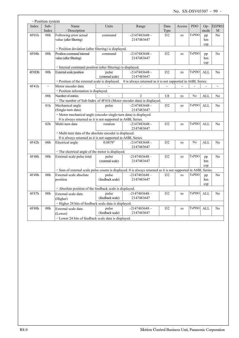
No. SX-DSV03307 - 99 -
R8.0 Motion Control Business Unit, Panasonic Corporation
- Position system
Index Sub- Index
Name / Description
Units Range Data Type
Access PDO Op- mode
EEPROM
4F01h 00h Following error actual value (after filtering)
command -2147483648 - 2147483647
I32 ro TxPDO pp hm csp
No
・Position deviation (after filtering) is displayed. 4F04h 00h Position command internal
value (after filtering) command -2147483648 -
2147483647 I32 ro TxPDO pp
hm csp
No
・Internal command position (after filtering) is displayed. 4F0Dh 00h External scale position pulse
(external scale) -2147483648 - 2147483647
I32 ro TxPDO ALL No
・Position of the external scale is displayed. 0 is always returned as it is not supported in A6BL Series. 4F41h - Motor encoder data - - - - - - -
・Position information is displayed. 00h Number of entries - 2 U8 ro No ALL No
・The number of Sub-Index of 4F41h (Motor encoder data) is displayed. 01h Mechanical angle
(Single-turn data) pulse -2147483648 -
2147483647 I32 ro TxPDO ALL No
・Motor mechanical angle (encoder single-turn data) is displayed. 0 is always returned as it is not supported in A6BL Series.
02h Multi-turn data rotation -2147483648 - 2147483647
I32 ro TxPDO ALL No
・Multi-turn data of the absolute encoder is displayed. 0 is always returned as it is not supported in A6BL Series.
4F42h 00h Electrical angle 0.0879° -2147483648 - 2147483647
I32 ro No ALL No
・The electrical angle of the motor is displayed. 4F48h 00h External scale pulse total pulse
(external scale) -2147483648 –
2147483647 I32 ro TxPDO pp
hm csp
No
・Sum of external scale pulse counts is displayed. 0 is always returned as it is not supported in A6BL Series. 4F49h 00h External scale absolute
position pulse
(feedback scale) -2147483648 –
2147483647 I32 ro TxPDO pp
hm csp
No
・Absolute position of the feedback scale is displayed. 4F87h 00h External scale data
(Higher) pulse
(feedback scale) -2147483648 –
2147483647 I32 ro TxPDO ALL No
・Higher 24 bits of feedback scale data is displayed. 4F88h 00h External scale data
(Lower) pulse
(feedback scale) -2147483648 –
2147483647 I32 ro TxPDO ALL No
・Lower 24 bits of feedback scale data is displayed.
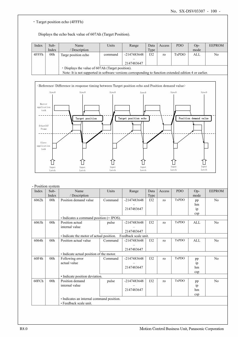
No. SX-DSV03307 - 100 -
R8.0 Motion Control Business Unit, Panasonic Corporation
・Target position echo (4FFFh)
Displays the echo back value of 607Ah (Target Position). Index Sub-
Index Name
/ Description Units Range Data
Type Access PDO Op-
mode EEPROM
4FFFh 00h Targe position echo command -2147483648 –
2147483647
I32 ro TxPDO ALL No
・Displays the value of 607Ah (Target position). Note: It is not supported in software versions corresponding to function extended edition 4 or earlier.
- Position system
Index Sub- Index
Name / Description
Units Range Data Type
Access PDO Op- mode
EEPROM
6062h 00h Position demand value Command -2147483648 -
2147483647
I32 ro TxPDO pp hm ip
csp
No
• Indicates a command position (= IPOS). 6063h 00h Position actual
internal value pulse -2147483648
– 2147483647
I32 ro TxPDO ALL No
• Indicate the motor of actual position. Feedback scale unit. 6064h 00h Position actual value Command -2147483648
– 2147483647
I32 ro TxPDO ALL No
• Indicate actual position of the motor. 60F4h 00h Following error
actual value Command -2147483648
– 2147483647
I32 ro TxPDO pp ip
hm csp
No
• Indicate position deviation. 60FCh 00h Position demand
internal value pulse -2147483648
– 2147483647
I32 ro TxPDO pp ip
hm csp
No
• Indicates an internal command position. • Feedback scale unit.
<Reference: Difference in response timing between Target position echo and Position demand value>
Master
application
task
EtherCAT
Frame
Sync0
Target position Target position echo
Sync0 Sync0 Sync0 Sync0 Sync0
Input
Latch
Input
Latch Input
Latch
Input
Latch Input
Latch
Input
Latch
Position demand value
Slave
application
task
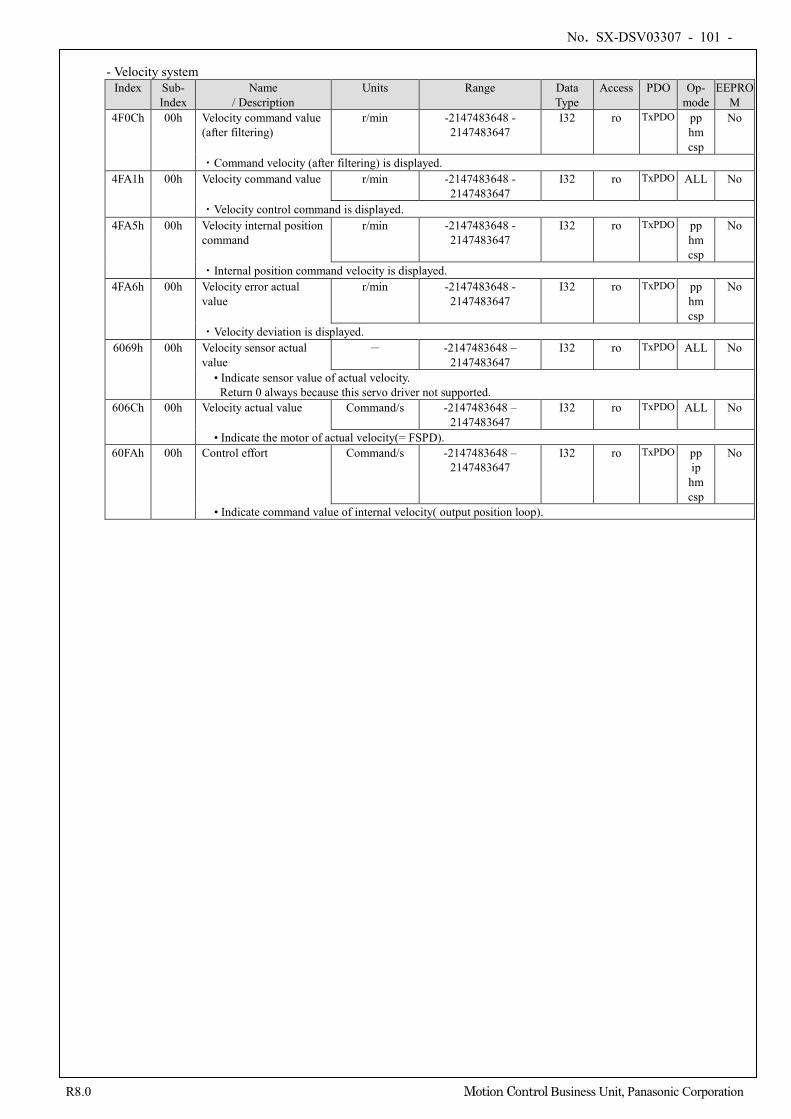
No. SX-DSV03307 - 101 -
R8.0 Motion Control Business Unit, Panasonic Corporation
- Velocity system
Index Sub- Index
Name / Description
Units Range Data Type
Access PDO Op- mode
EEPROM
4F0Ch 00h Velocity command value (after filtering)
r/min -2147483648 - 2147483647
I32 ro TxPDO pp hm csp
No
・Command velocity (after filtering) is displayed. 4FA1h 00h Velocity command value r/min -2147483648 -
2147483647 I32 ro TxPDO ALL No
・Velocity control command is displayed. 4FA5h 00h Velocity internal position
command r/min -2147483648 -
2147483647 I32 ro TxPDO pp
hm csp
No
・Internal position command velocity is displayed. 4FA6h 00h Velocity error actual
value r/min -2147483648 -
2147483647 I32 ro TxPDO pp
hm csp
No
・Velocity deviation is displayed. 6069h 00h Velocity sensor actual
value - -2147483648 –
2147483647 I32 ro TxPDO ALL No
• Indicate sensor value of actual velocity. Return 0 always because this servo driver not supported.
606Ch 00h Velocity actual value Command/s -2147483648 – 2147483647
I32 ro TxPDO ALL No
• Indicate the motor of actual velocity(= FSPD). 60FAh 00h Control effort Command/s -2147483648 –
2147483647 I32 ro TxPDO pp
ip hm csp
No
• Indicate command value of internal velocity( output position loop).
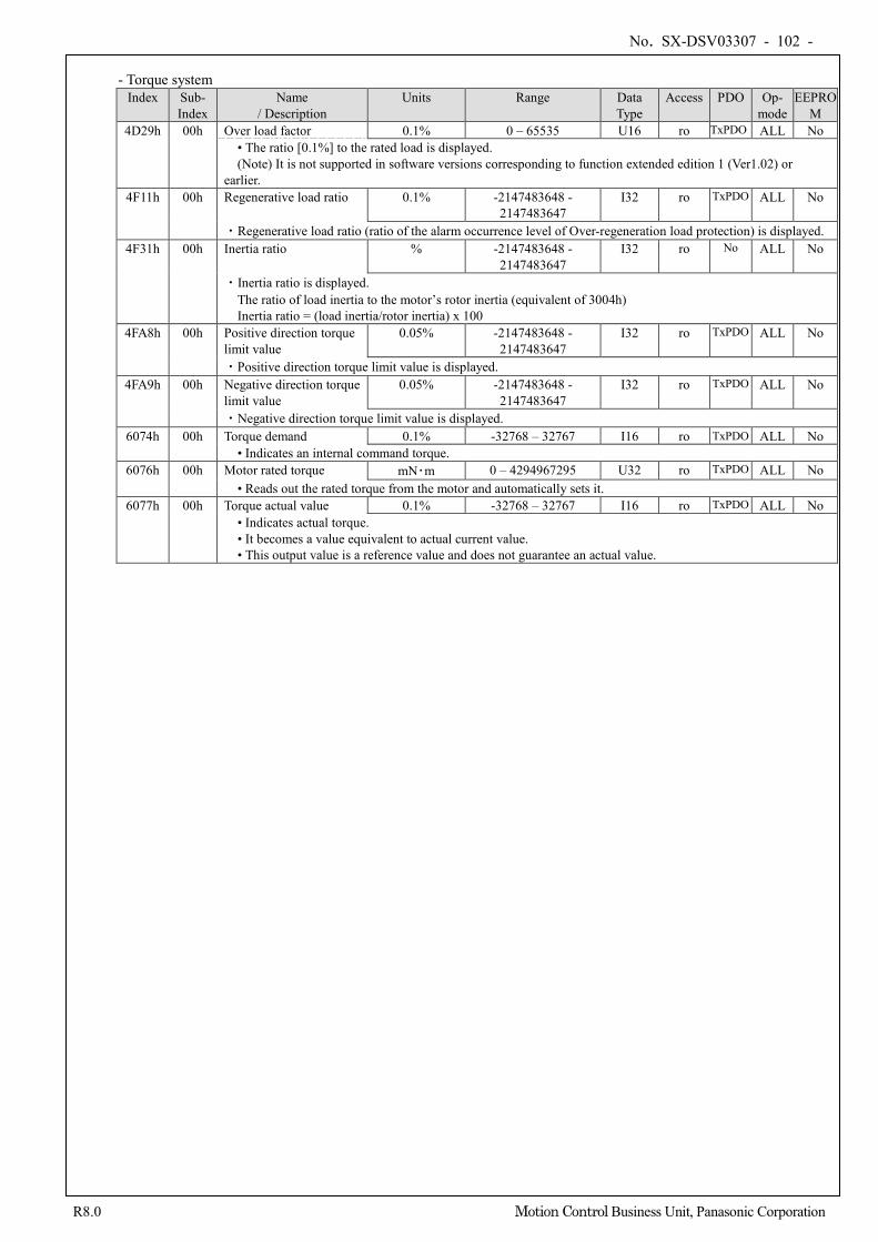
No. SX-DSV03307 - 102 -
R8.0 Motion Control Business Unit, Panasonic Corporation
- Torque system
Index Sub- Index
Name / Description
Units Range Data Type
Access PDO Op- mode
EEPROM
4D29h 00h Over load factor 0.1% 0 – 65535 U16 ro TxPDO ALL No • The ratio [0.1%] to the rated load is displayed. (Note) It is not supported in software versions corresponding to function extended edition 1 (Ver1.02) or
earlier. 4F11h 00h Regenerative load ratio 0.1% -2147483648 -
2147483647 I32 ro TxPDO ALL No
・Regenerative load ratio (ratio of the alarm occurrence level of Over-regeneration load protection) is displayed. 4F31h 00h Inertia ratio % -2147483648 -
2147483647 I32 ro No ALL No
・Inertia ratio is displayed. The ratio of load inertia to the motor’s rotor inertia (equivalent of 3004h) Inertia ratio = (load inertia/rotor inertia) x 100
4FA8h 00h Positive direction torque limit value
0.05% -2147483648 - 2147483647
I32 ro TxPDO ALL No
・Positive direction torque limit value is displayed. 4FA9h 00h Negative direction torque
limit value 0.05% -2147483648 -
2147483647 I32 ro TxPDO ALL No
・Negative direction torque limit value is displayed. 6074h 00h Torque demand 0.1% -32768 – 32767 I16 ro TxPDO ALL No
• Indicates an internal command torque. 6076h 00h Motor rated torque mN・m 0 – 4294967295 U32 ro TxPDO ALL No
• Reads out the rated torque from the motor and automatically sets it. 6077h 00h Torque actual value 0.1% -32768 – 32767 I16 ro TxPDO ALL No
• Indicates actual torque. • It becomes a value equivalent to actual current value. • This output value is a reference value and does not guarantee an actual value.
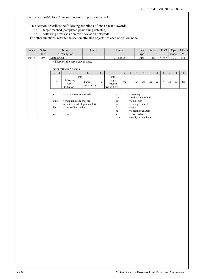
No. SX-DSV03307 - 103 -
R8.0 Motion Control Business Unit, Panasonic Corporation
- Statusword (6041h) <Common functions in position control> This section describes the following functions of 6041h (Statusword).
bit 10: target reached (completed positioning detected) bit 13: following error (position over-deviation detected)
For other functions, refer to the section "Related objects" of each operation mode.
Index Sub-
Index Name
/ Description Units Range Data
Type Access PDO Op-
mode EEPRO
M 6041h 00h Statusword - 0 - 65535 U16 ro TxPDO ALL No
• Displays the servo driver state. bit information details
15 - 14 13 12 11 10 9 8 7 6 5 4 3 2 1 0
r
oms
ila
oms
rm r w sod qs ve f oe so rtso following error
(only pp,csp)
(differ in operation mode)
target reached
(except csp) r = reserved (not supported) w = warning sod = switch on disabled oms = operation mode specific qs = quick stop (operation mode dependent bit) ve = voltage enabled ila = internal limit active f = fault oe = operation enabled rm = remote so = switched on rtso = ready to switch on
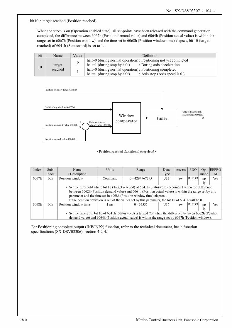
No. SX-DSV03307 - 104 -
R8.0 Motion Control Business Unit, Panasonic Corporation
bit10:target reached (Position reached)
When the servo is on (Operation enabled state), all set-points have been released with the command generation completed, the difference between 6062h (Position demand value) and 6064h (Position actual value) is within the range set in 6067h (Position window), and the time set in 6068h (Position window time) elapses, bit 10 (target reached) of 6041h (Statusword) is set to 1.
bit Name Value Definition
10 target reached
0 halt=0 (during normal operation) : Positioning not yet completed halt=1 (during stop by halt) : During axis deceleration
1 halt=0 (during normal operation) : Positioning completed halt=1 (during stop by halt) : Axis stop (Axis speed is 0.)
Index Sub-
Index Name
/ Description Units Range Data
Type Access PDO Op-
mode EEPRO
M 6067h 00h Position window Command 0 - 4294967295 U32 rw RxPDO pp
ip Yes
• Set the threshold where bit 10 (Target reached) of 6041h (Statusword) becomes 1 when the difference between 6062h (Position demand value) and 6064h (Position actual value) is within the range set by this parameter and the time set in 6068h (Position window time) elapses. If the position deviation is out of the values set by this parameter, the bit 10 of 6041h will be 0.
6068h 00h Position window time 1 ms 0 - 65535 U16 rw RxPDO pp ip
Yes
• Set the time until bit 10 of 6041h (Statusword) is turned ON when the difference between 6062h (Position demand value) and 6064h (Position actual value) is within the range set by 6067h (Position window).
For Positioning complete output (INP/INP2) function, refer to the technical document, basic function specifications (SX-DSV03306), section 4-2-4.
Window comparator
timer
Target reached in statusword (6041h)
Position window time (6068h)
<Position reached (functional overview)>
Positioning window (6067h)
Position actual value (6064h)
+
-
Following error actual value (60F4h) Position demand value (6062h)
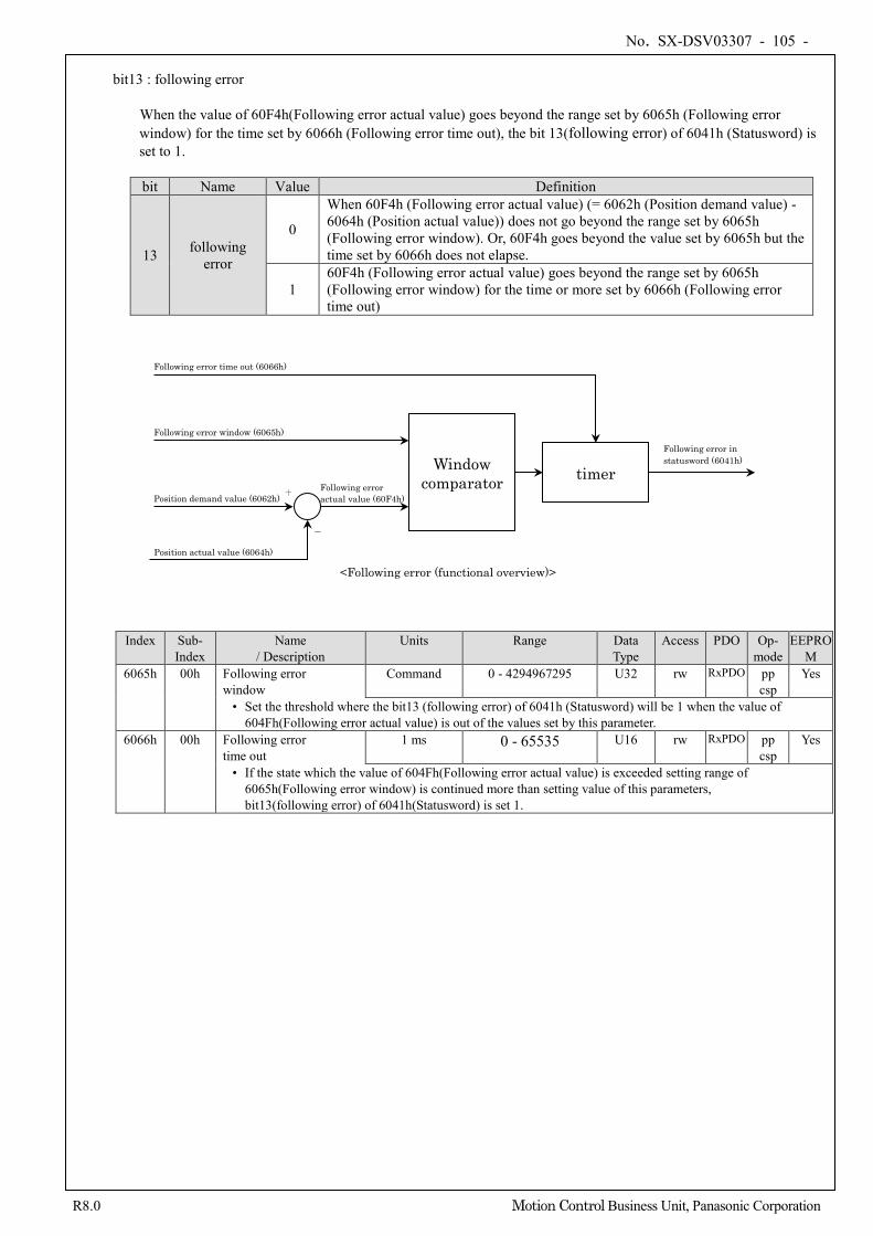
No. SX-DSV03307 - 105 -
R8.0 Motion Control Business Unit, Panasonic Corporation
bit13 : following error
When the value of 60F4h(Following error actual value) goes beyond the range set by 6065h (Following error window) for the time set by 6066h (Following error time out), the bit 13(following error) of 6041h (Statusword) is set to 1. bit Name Value Definition
13 following error
0
When 60F4h (Following error actual value) (= 6062h (Position demand value) - 6064h (Position actual value)) does not go beyond the range set by 6065h (Following error window). Or, 60F4h goes beyond the value set by 6065h but the time set by 6066h does not elapse.
1 60F4h (Following error actual value) goes beyond the range set by 6065h (Following error window) for the time or more set by 6066h (Following error time out)
Index Sub-
Index Name
/ Description Units Range Data
Type Access PDO Op-
mode EEPRO
M 6065h 00h Following error
window Command 0 - 4294967295 U32 rw RxPDO pp
csp Yes
• Set the threshold where the bit13 (following error) of 6041h (Statusword) will be 1 when the value of 604Fh(Following error actual value) is out of the values set by this parameter.
6066h 00h Following error time out
1 ms 0 - 65535 U16 rw RxPDO pp csp
Yes
• If the state which the value of 604Fh(Following error actual value) is exceeded setting range of 6065h(Following error window) is continued more than setting value of this parameters, bit13(following error) of 6041h(Statusword) is set 1.
Window comparator
timer
Position actual value (6064h)
Position demand value (6062h)
Following error in statusword (6041h)
Following error time out (6066h)
-
+
<Following error (functional overview)>
Following error window (6065h)
Following error actual value (60F4h)
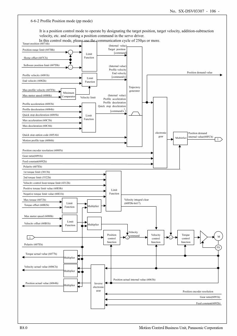
No. SX-DSV03307 - 106 -
R8.0 Motion Control Business Unit, Panasonic Corporation
6-6-2 Profile Position mode (pp mode)
It is a position control mode to operate by designating the target position, target velocity, addition-subtraction velocity, etc. and creating a position command in the servo driver.
In this control mode, please use the communication cycle of 250µs or more.
Position encoder resolution (608Fh)
Position range limit (607Bh) Target position (607Ah)
Software position limit (607Dh)
Limit Function
Limit Function
Profile velocity (6081h) End velocity (6082h)
Minimum Comparator Max motor speed (6080h)
Max profile velocity (607Fh)
Limit Function
Profile acceleration (6083h) Profile deceleration (6084h) Quick stop deceleration (6085h) Max acceleration (60C5h) Max deceleration (60C6h)
Quick stop option code (605Ah) Motion profile type (6086h)
(Internal value) Target position
[command]
(Internal value) Profile velocity
End velocity [command/s]
(Internal value) Profile acceleration Profile deceleration
Quick stop deceleration [command/s
2]
Trajectory generator
Velocity limit
Home offset (607Ch)
1 Position demand internal value(60FCh)
Position demand value
electronic gear Multiplier
Gear ratio(6091h) Feed constant(6092h)
1 Position control
function Velocity control
function + + Torque
control function
Velocity offset (60B1h)
Torque offset (60B2h)
M
FS
Position actual value (6064h)
Velocity actual value (606Ch)
Torque actual value (6077h)
Inverse electronic
gear
Position actual internal value (6063h)
Multiplier
Multiplier
Multiplier
Polarity (607Eh)
Position encoder resolution
Gear ratio(6091h) Feed constant(6092h)
Multiplier
Multiplier Limit Function
Max torque (6072h)
Limit Function
Max motor speed (6080h)
Polarity (607Eh)
Limit Function
-
-
Velocity command
1st torque limit (3013h) 2nd torque limit (3522h) Velocity control loop torque limit (4312h) Positive torque limit value (60E0h) Negative torque limit value (60E1h)
Velosity integral clear (60FDh-bit17)
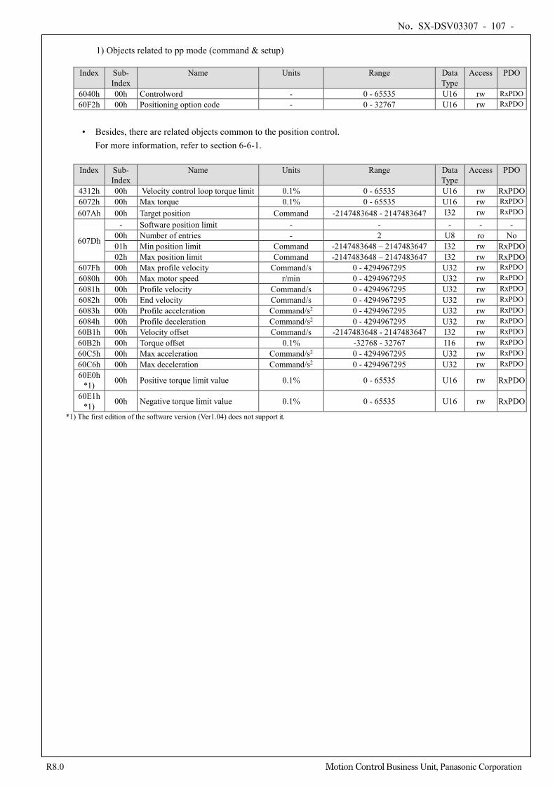
No. SX-DSV03307 - 107 -
R8.0 Motion Control Business Unit, Panasonic Corporation
1) Objects related to pp mode (command & setup)
Index Sub-
Index Name Units Range Data
Type Access PDO
6040h 00h Controlword - 0 - 65535 U16 rw RxPDO 60F2h 00h Positioning option code - 0 - 32767 U16 rw RxPDO
• Besides, there are related objects common to the position control.
For more information, refer to section 6-6-1. Index Sub-
Index Name Units Range Data
Type Access PDO
4312h 00h Velocity control loop torque limit 0.1% 0 - 65535 U16 rw RxPDO 6072h 00h Max torque 0.1% 0 - 65535 U16 rw RxPDO
607Ah 00h Target position Command -2147483648 - 2147483647 I32 rw RxPDO
607Dh
- Software position limit - - - - - 00h Number of entries - 2 U8 ro No 01h Min position limit Command -2147483648 – 2147483647 I32 rw RxPDO 02h Max position limit Command -2147483648 – 2147483647 I32 rw RxPDO
607Fh 00h Max profile velocity Command/s 0 - 4294967295 U32 rw RxPDO 6080h 00h Max motor speed r/min 0 - 4294967295 U32 rw RxPDO 6081h 00h Profile velocity Command/s 0 - 4294967295 U32 rw RxPDO 6082h 00h End velocity Command/s 0 - 4294967295 U32 rw RxPDO 6083h 00h Profile acceleration Command/s2 0 - 4294967295 U32 rw RxPDO 6084h 00h Profile deceleration Command/s2 0 - 4294967295 U32 rw RxPDO 60B1h 00h Velocity offset Command/s -2147483648 - 2147483647 I32 rw RxPDO 60B2h 00h Torque offset 0.1% -32768 - 32767 I16 rw RxPDO 60C5h 00h Max acceleration Command/s2 0 - 4294967295 U32 rw RxPDO 60C6h 00h Max deceleration Command/s2 0 - 4294967295 U32 rw RxPDO 60E0h
*1) 00h Positive torque limit value 0.1% 0 - 65535 U16 rw RxPDO
60E1h *1) 00h Negative torque limit value 0.1% 0 - 65535 U16 rw RxPDO
*1) The first edition of the software version (Ver1.04) does not support it.
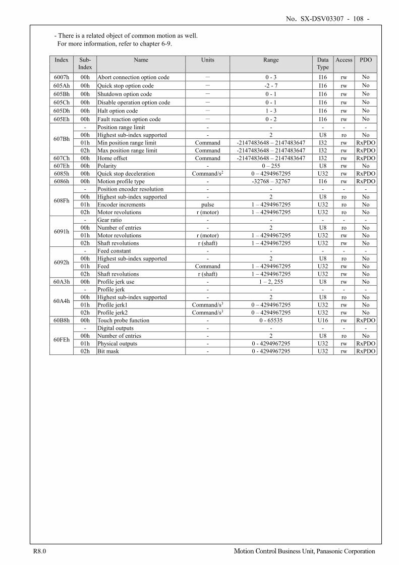
No. SX-DSV03307 - 108 -
R8.0 Motion Control Business Unit, Panasonic Corporation
- There is a related object of common motion as well. For more information, refer to chapter 6-9.
Index Sub-
Index Name Units Range Data
Type Access PDO
6007h 00h Abort connection option code - 0 - 3 I16 rw No 605Ah 00h Quick stop option code - -2 - 7 I16 rw No 605Bh 00h Shutdown option code - 0 - 1 I16 rw No 605Ch 00h Disable operation option code - 0 - 1 I16 rw No 605Dh 00h Halt option code - 1 - 3 I16 rw No 605Eh 00h Fault reaction option code - 0 - 2 I16 rw No
607Bh
- Position range limit - - - - - 00h Highest sub-index supported - 2 U8 ro No 01h Min position range limit Command -2147483648 – 2147483647 I32 rw RxPDO 02h Max position range limit Command -2147483648 – 2147483647 I32 rw RxPDO
607Ch 00h Home offset Command -2147483648 – 2147483647 I32 rw RxPDO 607Eh 00h Polarity - 0 – 255 U8 rw No 6085h 00h Quick stop deceleration Command/s2 0 – 4294967295 U32 rw RxPDO 6086h 00h Motion profile type - -32768 – 32767 I16 rw RxPDO
608Fh
- Position encoder resolution - - - - - 00h Highest sub-index supported - 2 U8 ro No 01h Encoder increments pulse 1 – 4294967295 U32 ro No 02h Motor revolutions r (motor) 1 – 4294967295 U32 ro No
6091h
- Gear ratio - - - - - 00h Number of entries - 2 U8 ro No 01h Motor revolutions r (motor) 1 – 4294967295 U32 rw No 02h Shaft revolutions r (shaft) 1 – 4294967295 U32 rw No
6092h
- Feed constant - - - - - 00h Highest sub-index supported - 2 U8 ro No 01h Feed Command 1 – 4294967295 U32 rw No 02h Shaft revolutions r (shaft) 1 – 4294967295 U32 rw No
60A3h 00h Profile jerk use - 1 – 2, 255 U8 rw No
60A4h
- Profile jerk - - - - - 00h Highest sub-index supported - 2 U8 ro No 01h Profile jerk1 Command/s3 0 – 4294967295 U32 rw No 02h Profile jerk2 Command/s3 0 – 4294967295 U32 rw No
60B8h 00h Touch probe function - 0 - 65535 U16 rw RxPDO
60FEh
- Digital outputs - - - - - 00h Number of entries - 2 U8 ro No 01h Physical outputs - 0 - 4294967295 U32 rw RxPDO 02h Bit mask - 0 - 4294967295 U32 rw RxPDO
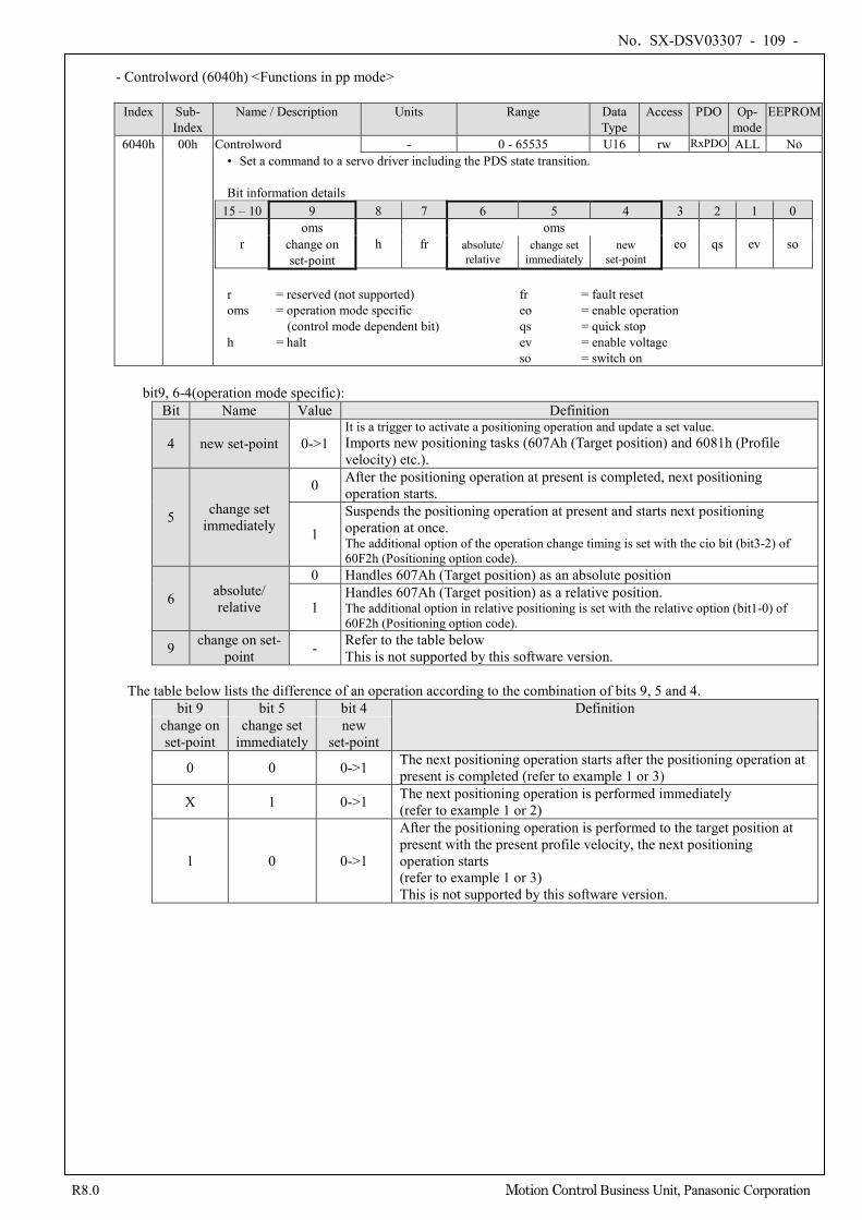
No. SX-DSV03307 - 109 -
R8.0 Motion Control Business Unit, Panasonic Corporation
- Controlword (6040h) <Functions in pp mode>
Index Sub-
Index Name / Description Units Range Data
Type Access PDO Op-
mode EEPROM
6040h 00h Controlword - 0 - 65535 U16 rw RxPDO ALL No • Set a command to a servo driver including the PDS state transition. Bit information details
15 – 10 9 8 7 6 5 4 3 2 1 0
r oms
h fr oms
eo qs ev so change on set-point
absolute/ relative
change set immediately
new set-point
r = reserved (not supported) fr = fault reset oms = operation mode specific eo = enable operation
(control mode dependent bit) qs = quick stop h = halt ev = enable voltage
so = switch on
bit9, 6-4(operation mode specific): Bit Name Value Definition
4 new set-point 0->1 It is a trigger to activate a positioning operation and update a set value. Imports new positioning tasks (607Ah (Target position) and 6081h (Profile velocity) etc.).
5 change set immediately
0 After the positioning operation at present is completed, next positioning operation starts.
1 Suspends the positioning operation at present and starts next positioning operation at once. The additional option of the operation change timing is set with the cio bit (bit3-2) of 60F2h (Positioning option code).
6 absolute/ relative
0 Handles 607Ah (Target position) as an absolute position
1 Handles 607Ah (Target position) as a relative position. The additional option in relative positioning is set with the relative option (bit1-0) of 60F2h (Positioning option code).
9 change on set-point - Refer to the table below
This is not supported by this software version.
The table below lists the difference of an operation according to the combination of bits 9, 5 and 4. bit 9 bit 5 bit 4 Definition
change on set-point
change set immediately
new set-point
0 0 0->1 The next positioning operation starts after the positioning operation at present is completed (refer to example 1 or 3)
X 1 0->1 The next positioning operation is performed immediately (refer to example 1 or 2)
1 0 0->1
After the positioning operation is performed to the target position at present with the present profile velocity, the next positioning operation starts (refer to example 1 or 3) This is not supported by this software version.
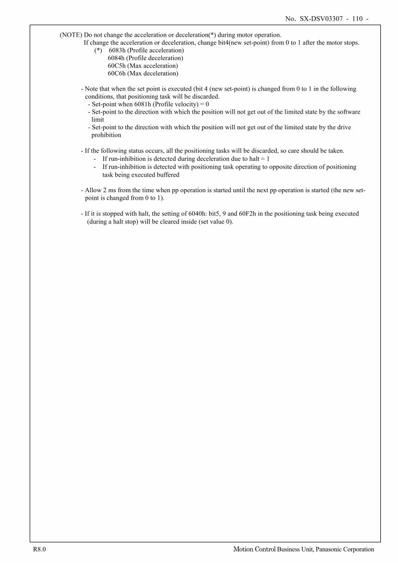
No. SX-DSV03307 - 110 -
R8.0 Motion Control Business Unit, Panasonic Corporation
(NOTE) Do not change the acceleration or deceleration(*) during motor operation. If change the acceleration or deceleration, change bit4(new set-point) from 0 to 1 after the motor stops.
(*) 6083h (Profile acceleration) 6084h (Profile deceleration) 60C5h (Max acceleration) 60C6h (Max deceleration) - Note that when the set point is executed (bit 4 (new set-point) is changed from 0 to 1 in the following
conditions, that positioning task will be discarded. - Set-point when 6081h (Profile velocity) = 0 - Set-point to the direction with which the position will not get out of the limited state by the software
limit - Set-point to the direction with which the position will not get out of the limited state by the drive
prohibition - If the following status occurs, all the positioning tasks will be discarded, so care should be taken.
- If run-inhibition is detected during deceleration due to halt = 1 - If run-inhibition is detected with positioning task operating to opposite direction of positioning
task being executed buffered - Allow 2 ms from the time when pp operation is started until the next pp operation is started (the new set-
point is changed from 0 to 1). - If it is stopped with halt, the setting of 6040h: bit5, 9 and 60F2h in the positioning task being executed
(during a halt stop) will be cleared inside (set value 0).
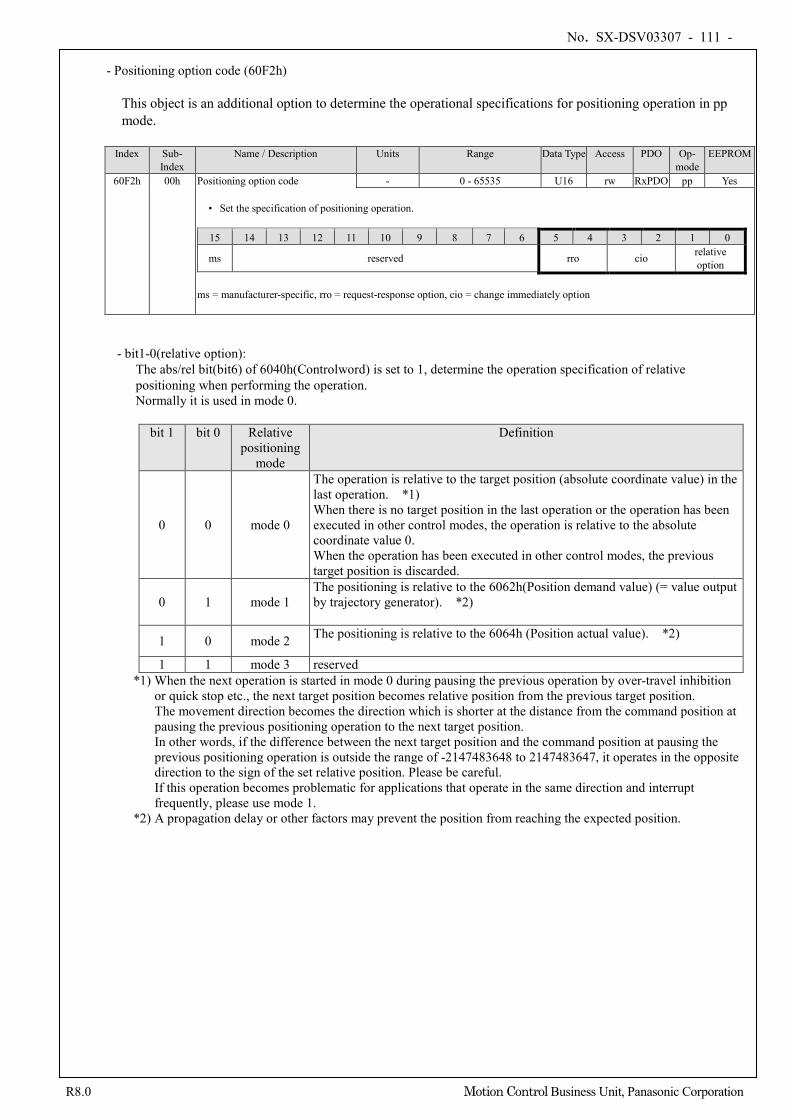
No. SX-DSV03307 - 111 -
R8.0 Motion Control Business Unit, Panasonic Corporation
- Positioning option code (60F2h)
This object is an additional option to determine the operational specifications for positioning operation in pp mode.
Index Sub-
Index Name / Description Units Range Data Type Access PDO Op-
mode EEPROM
60F2h 00h Positioning option code - 0 - 65535 U16 rw RxPDO pp Yes • Set the specification of positioning operation.
15 14 13 12 11 10 9 8 7 6 5 4 3 2 1 0
ms reserved rro cio relative option
ms = manufacturer-specific, rro = request-response option, cio = change immediately option
- bit1-0(relative option):
The abs/rel bit(bit6) of 6040h(Controlword) is set to 1, determine the operation specification of relative positioning when performing the operation. Normally it is used in mode 0.
bit 1 bit 0 Relative positioning
mode
Definition
0 0 mode 0
The operation is relative to the target position (absolute coordinate value) in the last operation. *1) When there is no target position in the last operation or the operation has been executed in other control modes, the operation is relative to the absolute coordinate value 0. When the operation has been executed in other control modes, the previous target position is discarded.
0 1 mode 1 The positioning is relative to the 6062h(Position demand value) (= value output by trajectory generator). *2)
1 0 mode 2 The positioning is relative to the 6064h (Position actual value). *2)
1 1 mode 3 reserved *1) When the next operation is started in mode 0 during pausing the previous operation by over-travel inhibition
or quick stop etc., the next target position becomes relative position from the previous target position. The movement direction becomes the direction which is shorter at the distance from the command position at pausing the previous positioning operation to the next target position. In other words, if the difference between the next target position and the command position at pausing the previous positioning operation is outside the range of -2147483648 to 2147483647, it operates in the opposite direction to the sign of the set relative position. Please be careful. If this operation becomes problematic for applications that operate in the same direction and interrupt frequently, please use mode 1.
*2) A propagation delay or other factors may prevent the position from reaching the expected position.
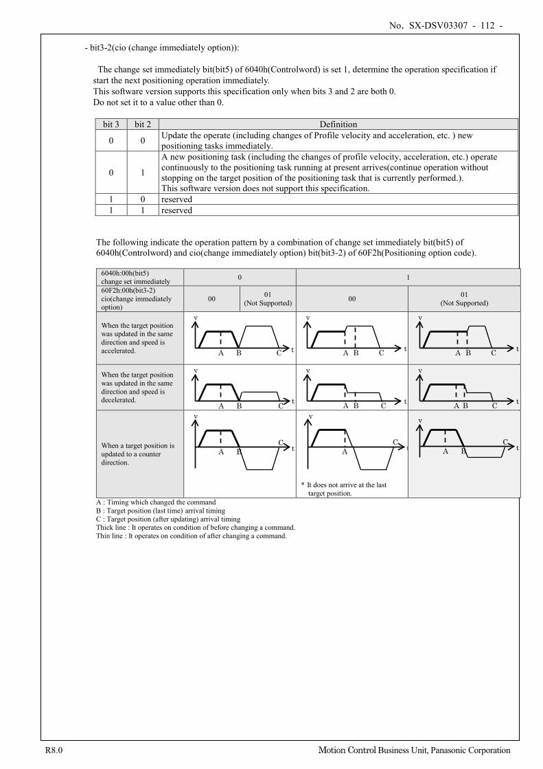
No. SX-DSV03307 - 112 -
R8.0 Motion Control Business Unit, Panasonic Corporation
- bit3-2(cio (change immediately option)):
The change set immediately bit(bit5) of 6040h(Controlword) is set 1, determine the operation specification if start the next positioning operation immediately. This software version supports this specification only when bits 3 and 2 are both 0. Do not set it to a value other than 0.
bit 3 bit 2 Definition
0 0 Update the operate (including changes of Profile velocity and acceleration, etc. ) new positioning tasks immediately.
0 1
A new positioning task (including the changes of profile velocity, acceleration, etc.) operate continuously to the positioning task running at present arrives(continue operation without stopping on the target position of the positioning task that is currently performed.). This software version does not support this specification.
1 0 reserved 1 1 reserved
The following indicate the operation pattern by a combination of change set immediately bit(bit5) of 6040h(Controlword) and cio(change immediately option) bit(bit3-2) of 60F2h(Positioning option code).
6040h:00h(bit5) change set immediately 0 1
60F2h:00h(bit3-2) cio(change immediately option)
00 01 (Not Supported) 00 01
(Not Supported)
When the target position was updated in the same direction and speed is accelerated.
When the target position was updated in the same direction and speed is decelerated.
When a target position is updated to a counter direction.
* It does not arrive at the last target position.
A : Timing which changed the command B : Target position (last time) arrival timing C : Target position (after updating) arrival timing Thick line : It operates on condition of before changing a command. Thin line : It operates on condition of after changing a command.
A B C t
v
A B C t
v
A B C t
v
A B C t
v
A B C t
v
A B C t
v
A B C
t
v
A C
t
v
A B C
t
v
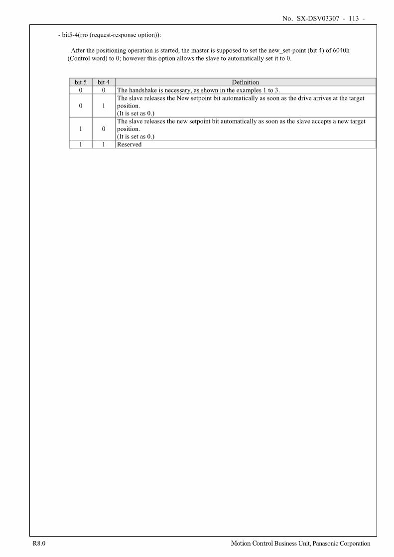
No. SX-DSV03307 - 113 -
R8.0 Motion Control Business Unit, Panasonic Corporation
- bit5-4(rro (request-response option)):
After the positioning operation is started, the master is supposed to set the new_set-point (bit 4) of 6040h (Control word) to 0; however this option allows the slave to automatically set it to 0.
bit 5 bit 4 Definition 0 0 The handshake is necessary, as shown in the examples 1 to 3.
0 1 The slave releases the New setpoint bit automatically as soon as the drive arrives at the target position. (It is set as 0.)
1 0 The slave releases the new setpoint bit automatically as soon as the slave accepts a new target position. (It is set as 0.)
1 1 Reserved
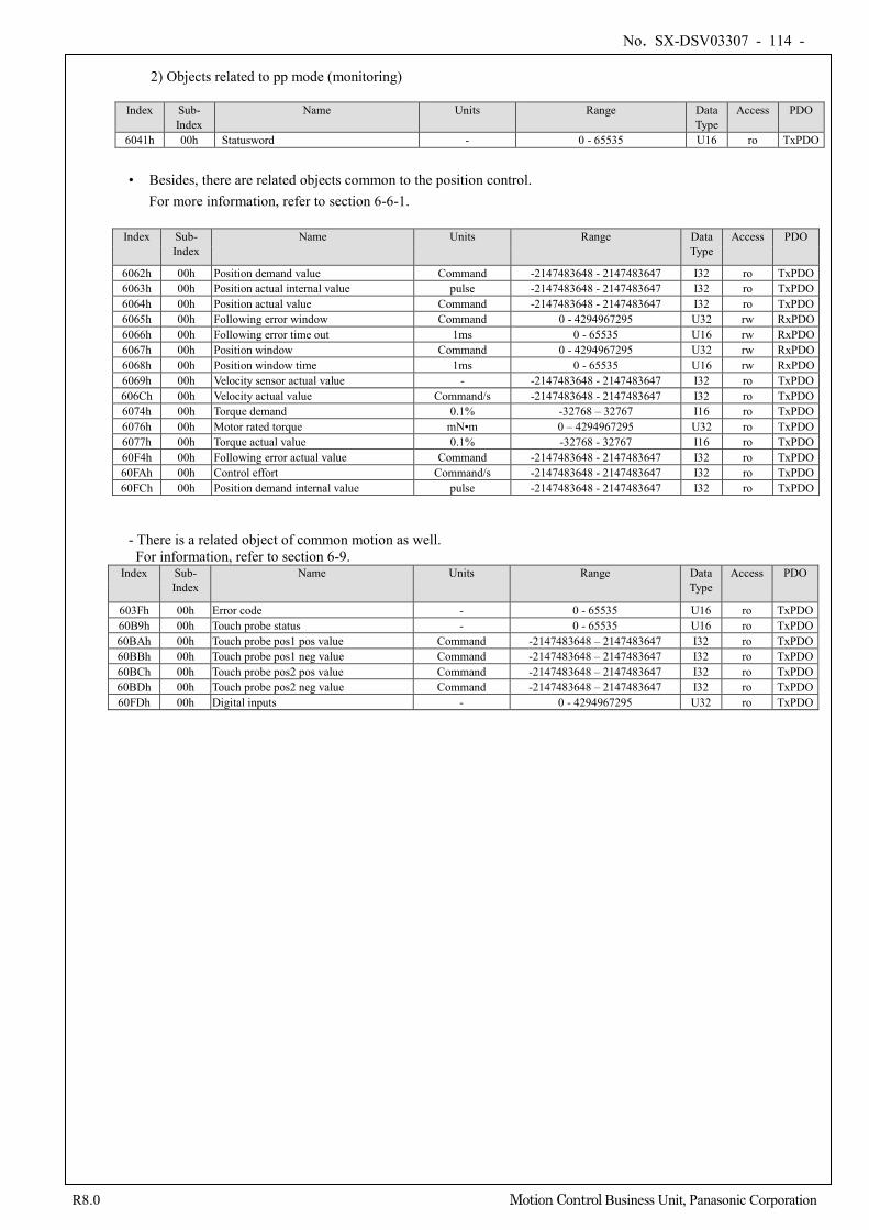
No. SX-DSV03307 - 114 -
R8.0 Motion Control Business Unit, Panasonic Corporation
2) Objects related to pp mode (monitoring) Index Sub-
Index Name Units Range Data
Type Access PDO
6041h 00h Statusword - 0 - 65535 U16 ro TxPDO
• Besides, there are related objects common to the position control. For more information, refer to section 6-6-1.
Index Sub-
Index Name Units Range Data
Type Access PDO
6062h 00h Position demand value Command -2147483648 - 2147483647 I32 ro TxPDO 6063h 00h Position actual internal value pulse -2147483648 - 2147483647 I32 ro TxPDO 6064h 00h Position actual value Command -2147483648 - 2147483647 I32 ro TxPDO 6065h 00h Following error window Command 0 - 4294967295 U32 rw RxPDO 6066h 00h Following error time out 1ms 0 - 65535 U16 rw RxPDO 6067h 00h Position window Command 0 - 4294967295 U32 rw RxPDO 6068h 00h Position window time 1ms 0 - 65535 U16 rw RxPDO 6069h 00h Velocity sensor actual value - -2147483648 - 2147483647 I32 ro TxPDO 606Ch 00h Velocity actual value Command/s -2147483648 - 2147483647 I32 ro TxPDO 6074h 00h Torque demand 0.1% -32768 – 32767 I16 ro TxPDO 6076h 00h Motor rated torque mN•m 0 – 4294967295 U32 ro TxPDO 6077h 00h Torque actual value 0.1% -32768 - 32767 I16 ro TxPDO 60F4h 00h Following error actual value Command -2147483648 - 2147483647 I32 ro TxPDO 60FAh 00h Control effort Command/s -2147483648 - 2147483647 I32 ro TxPDO 60FCh 00h Position demand internal value pulse -2147483648 - 2147483647 I32 ro TxPDO
- There is a related object of common motion as well. For information, refer to section 6-9.
Index Sub- Index
Name Units Range Data Type
Access PDO
603Fh 00h Error code - 0 - 65535 U16 ro TxPDO 60B9h 00h Touch probe status - 0 - 65535 U16 ro TxPDO 60BAh 00h Touch probe pos1 pos value Command -2147483648 – 2147483647 I32 ro TxPDO 60BBh 00h Touch probe pos1 neg value Command -2147483648 – 2147483647 I32 ro TxPDO 60BCh 00h Touch probe pos2 pos value Command -2147483648 – 2147483647 I32 ro TxPDO 60BDh 00h Touch probe pos2 neg value Command -2147483648 – 2147483647 I32 ro TxPDO 60FDh 00h Digital inputs - 0 - 4294967295 U32 ro TxPDO
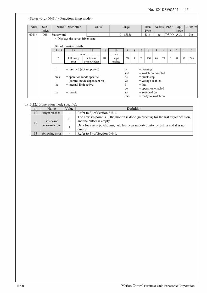
No. SX-DSV03307 - 115 -
R8.0 Motion Control Business Unit, Panasonic Corporation
- Statusword (6041h) <Functions in pp mode>
Index Sub-
Index Name / Description Units Range Data
Type Access PDO Op-
mode EEPROM
6041h 00h Statusword - 0 - 65535 U16 ro TxPDO ALL No • Displays the servo driver state. Bit information details 15 - 14 13 12 11 10 9 8 7 6 5 4 3 2 1 0
r oms
ila oms
rm r w sod qs ve f oe so rtso following error
set-point acknowledge
target reached
r = reserved (not supported) w = warning
sod = switch on disabled oms = operation mode specific qs = quick stop
(control mode dependent bit) ve = voltage enabled ila = internal limit active f = fault
oe = operation enabled rm = remote so = switched on
rtso = ready to switch on
bit13,12,10(operation mode specific): bit Name Value Definition 10 target reached - Refer to 3) of Section 6-6-1.
12 set-point acknowledge
0 The new set-point is 0, the motion is done (in process) for the last target position, and the buffer is empty
1 Data for a new positioning task has been imported into the buffer and it is not empty
13 following error - Refer to 3) of Section 6-6-1.
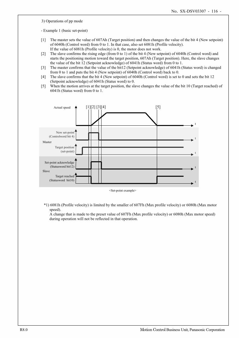
No. SX-DSV03307 - 116 -
R8.0 Motion Control Business Unit, Panasonic Corporation
3) Operations of pp mode
- Example 1 (basic set-point) [1] The master sets the value of 607Ah (Target position) and then changes the value of the bit 4 (New setpoint)
of 6040h (Control word) from 0 to 1. In that case, also set 6081h (Profile velocity). If the value of 6081h (Profile velocity) is 0, the motor does not work.
[2] The slave confirms the rising edge (from 0 to 1) of the bit 4 (New setpoint) of 6040h (Control word) and starts the positioning motion toward the target position, 607Ah (Target position). Here, the slave changes the value of the bit 12 (Setpoint acknowledge) of 6041h (Status word) from 0 to 1.
[3] The master confirms that the value of the bit12 (Setpoint acknowledge) of 6041h (Status word) is changed from 0 to 1 and puts the bit 4 (New setpoint) of 6040h (Control word) back to 0.
[4] The slave confirms that the bit 4 (New setpoint) of 6040h (Control word) is set to 0 and sets the bit 12 (Setpoint acknowledge) of 6041h (Status word) to 0.
[5] When the motion arrives at the target position, the slave changes the value of the bit 10 (Target reached) of 6041h (Status word) from 0 to 1.
*1) 6081h (Profile velocity) is limited by the smaller of 607Fh (Max profile velocity) or 6080h (Max motor speed). A change that is made to the preset value of 607Fh (Max profile velocity) or 6080h (Max motor speed) during operation will not be reflected in that operation.
Actual speed [1][2] [3][4] [5]
New set-point (Controlword bit 4)
Target position (set-point)
t
t
t
t Set-point acknowledge
(Statusword bit12)
t
Target reached (Statusword bit10)
<Set-point example>
Master
Slave
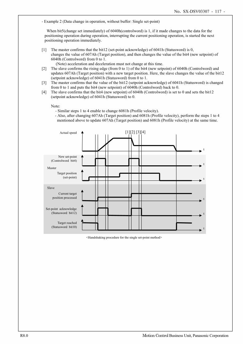
No. SX-DSV03307 - 117 -
R8.0 Motion Control Business Unit, Panasonic Corporation
- Example 2 (Data change in operation, without buffer: Single set-point)
When bit5(change set immediately) of 6040h(controlword) is 1, if it made changes to the data for the positioning operation during operation, interrupting the current positioning operation, is started the next positioning operation immediately.
[1] The master confirms that the bit12 (set-point acknowledge) of 6041h (Statusword) is 0,
changes the value of 607Ah (Target position), and then changes the value of the bit4 (new setpoint) of 6040h (Controlword) from 0 to 1.
(Note) acceleration and deceleration must not change at this time. [2] The slave confirms the rising edge (from 0 to 1) of the bit4 (new setpoint) of 6040h (Controlword) and
updates 607Ah (Target position) with a new target position. Here, the slave changes the value of the bit12 (setpoint acknowledge) of 6041h (Statusword) from 0 to 1.
[3] The master confirms that the value of the bit12 (setpoint acknowledge) of 6041h (Statusword) is changed from 0 to 1 and puts the bit4 (new setpoint) of 6040h (Controlword) back to 0.
[4] The slave confirms that the bit4 (new setpoint) of 6040h (Controlword) is set to 0 and sets the bit12 (setpoint acknowledge) of 6041h (Statusword) to 0. Note:
- Similar steps 1 to 4 enable to change 6081h (Profile velocity). - Also, after changing 607Ah (Target position) and 6081h (Profile velocity), perform the steps 1 to 4 mentioned above to update 607Ah (Target position) and 6081h (Profile velocity) at the same time.
Actual speed
New set-point (Controlword bit4)
Target position (set-point)
t
t
t
t Set-point acknowledge
(Statusword bit12)
t
Target reached (Statusword bit10)
<Handshaking procedure for the single set-point method>
[1][2] [3][4]
t Current target
position processed
Master
Slave
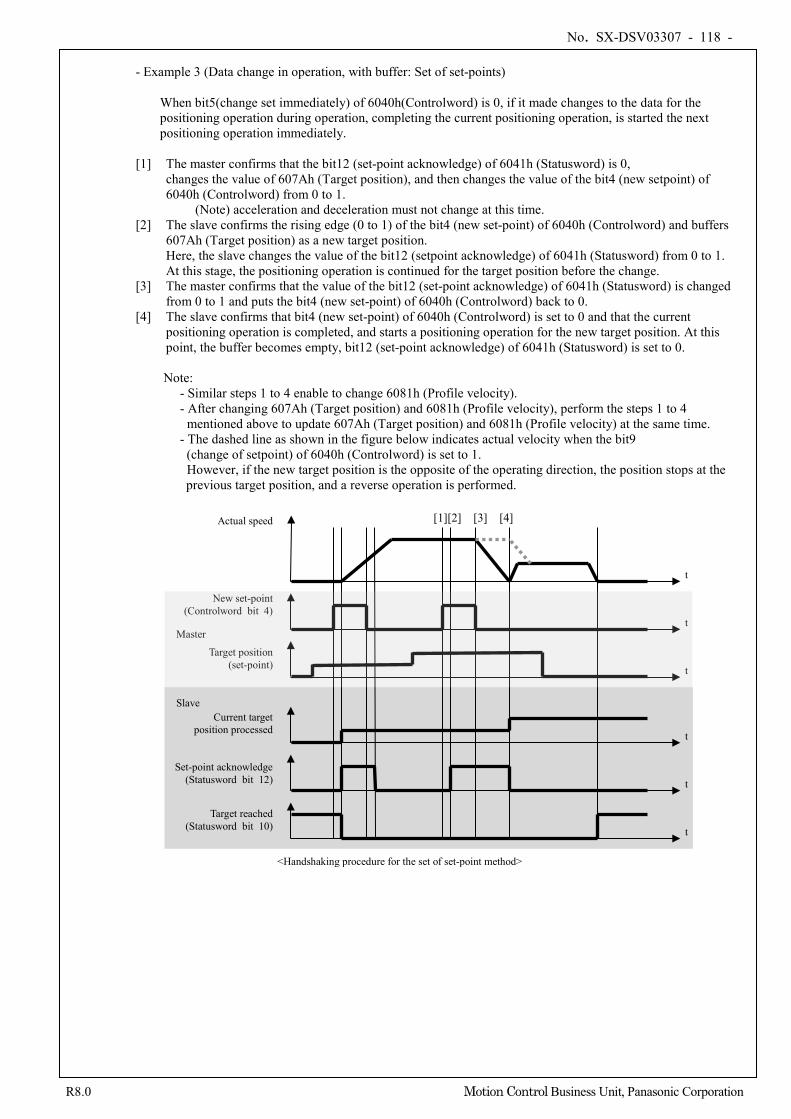
No. SX-DSV03307 - 118 -
R8.0 Motion Control Business Unit, Panasonic Corporation
- Example 3 (Data change in operation, with buffer: Set of set-points)
When bit5(change set immediately) of 6040h(Controlword) is 0, if it made changes to the data for the positioning operation during operation, completing the current positioning operation, is started the next positioning operation immediately.
[1] The master confirms that the bit12 (set-point acknowledge) of 6041h (Statusword) is 0,
changes the value of 607Ah (Target position), and then changes the value of the bit4 (new setpoint) of 6040h (Controlword) from 0 to 1.
(Note) acceleration and deceleration must not change at this time. [2] The slave confirms the rising edge (0 to 1) of the bit4 (new set-point) of 6040h (Controlword) and buffers
607Ah (Target position) as a new target position. Here, the slave changes the value of the bit12 (setpoint acknowledge) of 6041h (Statusword) from 0 to 1. At this stage, the positioning operation is continued for the target position before the change.
[3] The master confirms that the value of the bit12 (set-point acknowledge) of 6041h (Statusword) is changed from 0 to 1 and puts the bit4 (new set-point) of 6040h (Controlword) back to 0.
[4] The slave confirms that bit4 (new set-point) of 6040h (Controlword) is set to 0 and that the current positioning operation is completed, and starts a positioning operation for the new target position. At this point, the buffer becomes empty, bit12 (set-point acknowledge) of 6041h (Statusword) is set to 0.
Note:
- Similar steps 1 to 4 enable to change 6081h (Profile velocity). - After changing 607Ah (Target position) and 6081h (Profile velocity), perform the steps 1 to 4
mentioned above to update 607Ah (Target position) and 6081h (Profile velocity) at the same time. - The dashed line as shown in the figure below indicates actual velocity when the bit9
(change of setpoint) of 6040h (Controlword) is set to 1. However, if the new target position is the opposite of the operating direction, the position stops at the previous target position, and a reverse operation is performed.
Actual speed
New set-point (Controlword bit 4)
Target position (set-point)
t
t
t
t Set-point acknowledge
(Statusword bit 12)
t
Target reached (Statusword bit 10)
<Handshaking procedure for the set of set-point method>
[1][2] [3] [4]
t
Current target position processed
Slave
Master
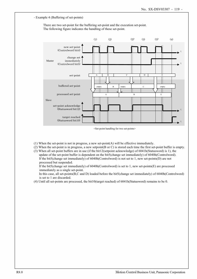
No. SX-DSV03307 - 119 -
R8.0 Motion Control Business Unit, Panasonic Corporation
- Example 4 (Buffering of set-points)
There are two set-point for the buffering set-point and the execution set-point. The following figure indicates the handling of these set-point.
(1) When the set-point is not in progress, a new set-point(A) will be effective immediately. (2) When the set-point is in progress, a new setpoint(B or C) is stored each time the first set-point buffer is empty. (3) When all set-point buffers are in use (if the bit12(setpoint acknowledge) of 6041h(Statusword) is 1), the
update of the set-point buffer is dependent on the bit5(change set immediately) of 6040h(Controlword). If the bit5(change set immediately) of 6040h(Controlword) is not set to 1, new set-points(D) are not processed but suspended. If the bit5(change set immediately) of 6040h(Controlword) is set to 1, new set-points(E) are processed immediately as a single set-point. In this case, all set-points(B,C and D) loaded before the bit5(change set immediately) of 6040h(Controlword) is set to 1 are discarded.
(4) Until all set-points are processed, the bit10(target reached) of 6041h(Statusword) remains to be 0.
new set-point (Controlword bit4) t
t
set-point acknowledge (Statusword bit12)
t
target reached (Statusword bit10)
<Set-point handling for two set-points>
t
change set immediately
(Controlword bit5)
processed set-point
buffered set-point
set-point A B C D E
A
B
B
C
E
(1) (2) (3) (4) (3)'
empty empty empty
(2)'
Master
Slave
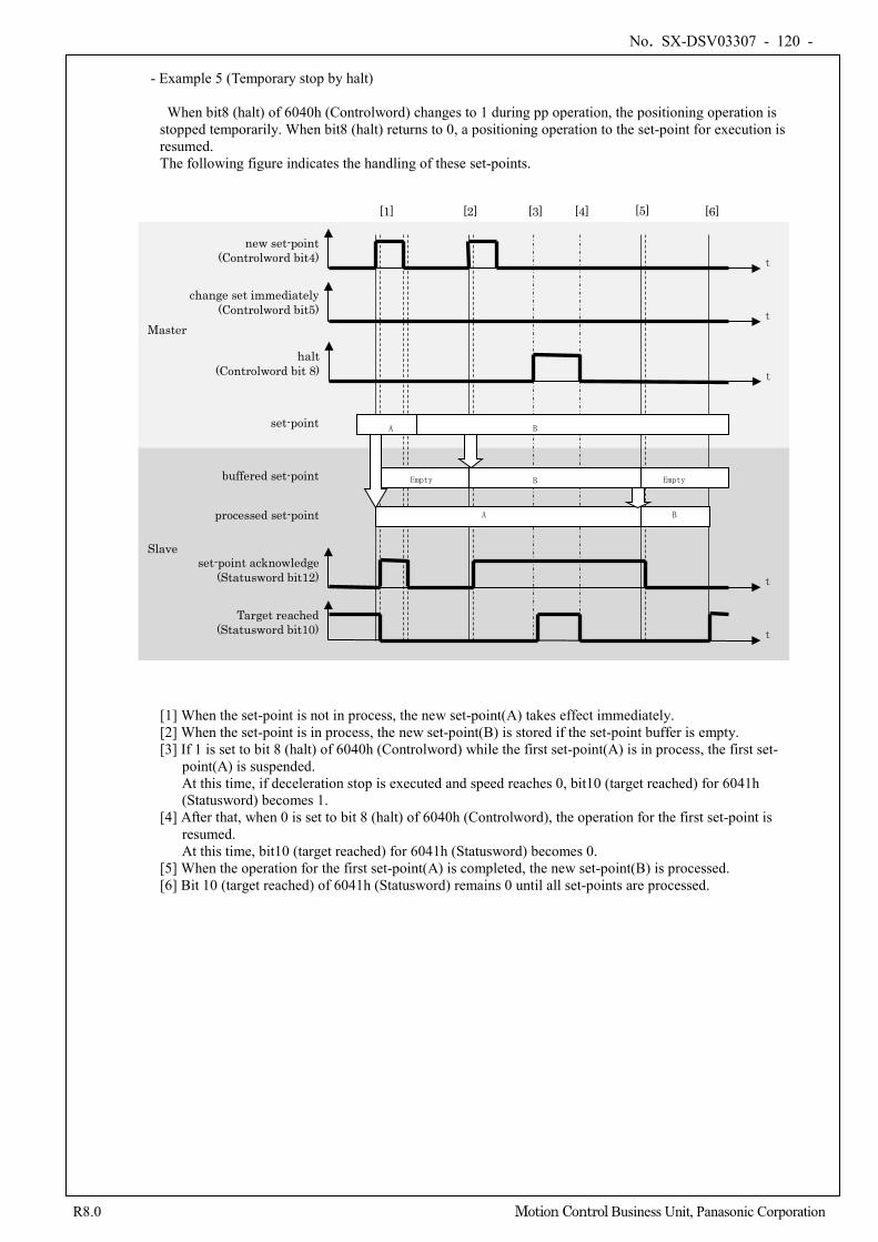
No. SX-DSV03307 - 120 -
R8.0 Motion Control Business Unit, Panasonic Corporation
- Example 5 (Temporary stop by halt)
When bit8 (halt) of 6040h (Controlword) changes to 1 during pp operation, the positioning operation is
stopped temporarily. When bit8 (halt) returns to 0, a positioning operation to the set-point for execution is resumed. The following figure indicates the handling of these set-points.
[1] When the set-point is not in process, the new set-point(A) takes effect immediately. [2] When the set-point is in process, the new set-point(B) is stored if the set-point buffer is empty. [3] If 1 is set to bit 8 (halt) of 6040h (Controlword) while the first set-point(A) is in process, the first set-
point(A) is suspended. At this time, if deceleration stop is executed and speed reaches 0, bit10 (target reached) for 6041h (Statusword) becomes 1.
[4] After that, when 0 is set to bit 8 (halt) of 6040h (Controlword), the operation for the first set-point is resumed. At this time, bit10 (target reached) for 6041h (Statusword) becomes 0.
[5] When the operation for the first set-point(A) is completed, the new set-point(B) is processed. [6] Bit 10 (target reached) of 6041h (Statusword) remains 0 until all set-points are processed.
new set-point (Controlword bit4) t
t
set-point acknowledge (Statusword bit12)
t
Target reached (Statusword bit10)
t
change set immediately (Controlword bit5)
processed set-point
buffered set-point
set-point A B
A
B
B
[1] [2] [4] [5]
Empty Empty
halt (Controlword bit 8) t
[3] [6]
Master
Slave
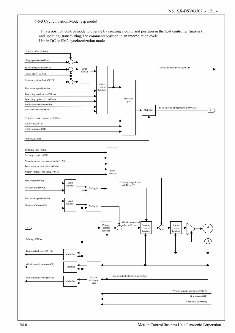
No. SX-DSV03307 - 121 -
R8.0 Motion Control Business Unit, Panasonic Corporation
6-6-3 Cyclic Position Mode (csp mode)
It is a position control mode to operate by creating a command position in the host controller (master) and updating (transmitting) the command position in an interpolation cycle. Use in DC or SM2 synchronization mode.
+
Drive control function
+
Limit function
Position range limit (607Bh)
Software position limit (607Dh)
Multiplier
Quick stop deceleration (6085h)
Quick stop option code (605Ah)
Target position (607Ah)
Position offset (60B0h)
Position demand value (6062h)
Home offset (607Ch)
electronic gear
Feed constant(6092h)
Gear ratio(6091h)
Position encoder resolution (608Fh)
Position demand internal value(60FCh) 1
1 Position control function
Velocity control function
+ Torque control
function M
E
Feed constant(6092h)
Gear ratio(6091h)
Position encoder resolution (608Fh)
Position actual value (6064h)
Velocity actual value (606Ch)
Torque actual value (6077h)
Polarity (607Eh)
Position actual internal value (6063h)
1st torque limit (3013h)
2nd torque limit (3522h)
Max torque (6072h)
Torque offset (60B2h)
Max motor speed (6080h)
Velocity offset (60B1h)
Multiplier
Multiplier
Multiplier
Multiplier
Multiplier
Limit function
Limit function
Inverse electronic
gear
Polarity(607Eh)
Limit function
Max motor speed (6080h)
-
-
Profile deceleration (6084h)
Max deceleration (60C6h)
Velocity command value (4FA1h)
Velocity control loop torque limit (4312h) Positive torque limit value (60E0h) Negative torque limit value (60E1h)
Velosity integral clear (60FDh-bit17)
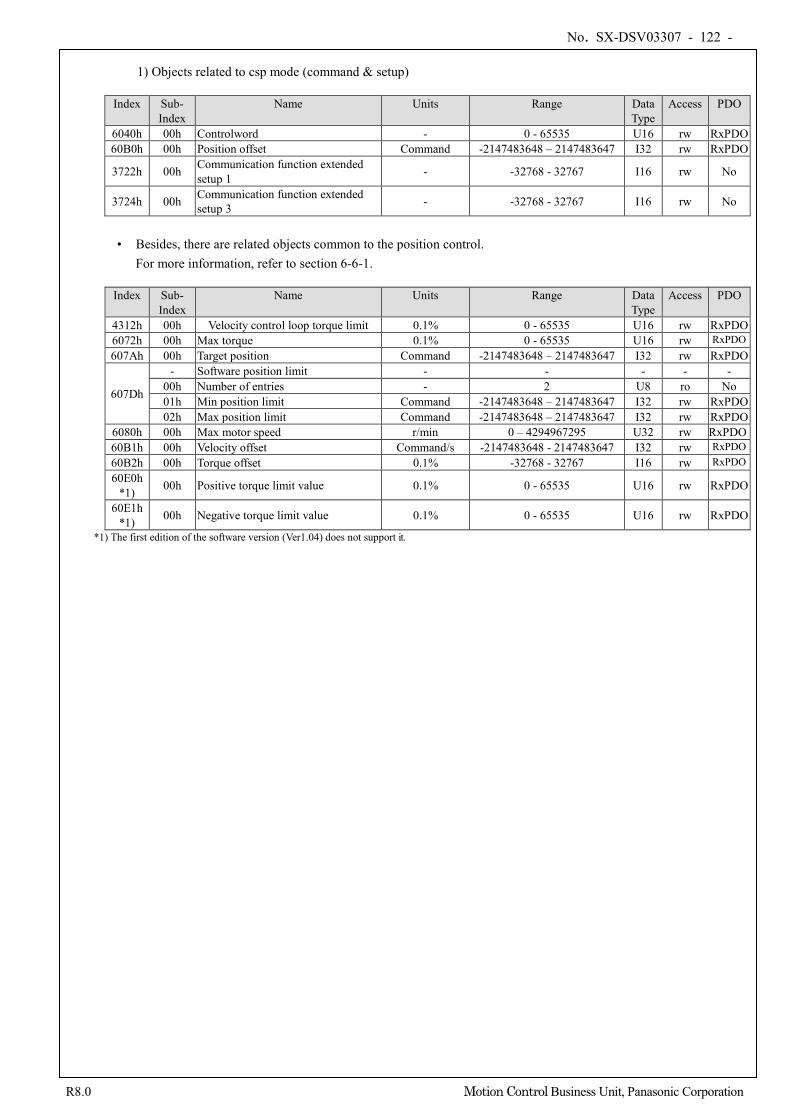
No. SX-DSV03307 - 122 -
R8.0 Motion Control Business Unit, Panasonic Corporation
1) Objects related to csp mode (command & setup)
Index Sub-
Index Name Units Range Data
Type Access PDO
6040h 00h Controlword - 0 - 65535 U16 rw RxPDO 60B0h 00h Position offset Command -2147483648 – 2147483647 I32 rw RxPDO
3722h 00h Communication function extended setup 1 - -32768 - 32767 I16 rw No
3724h 00h Communication function extended setup 3 - -32768 - 32767 I16 rw No
• Besides, there are related objects common to the position control.
For more information, refer to section 6-6-1.
Index Sub- Index
Name Units Range Data Type
Access PDO
4312h 00h Velocity control loop torque limit 0.1% 0 - 65535 U16 rw RxPDO 6072h 00h Max torque 0.1% 0 - 65535 U16 rw RxPDO 607Ah 00h Target position Command -2147483648 – 2147483647 I32 rw RxPDO
607Dh
- Software position limit - - - - - 00h Number of entries - 2 U8 ro No 01h Min position limit Command -2147483648 – 2147483647 I32 rw RxPDO 02h Max position limit Command -2147483648 – 2147483647 I32 rw RxPDO
6080h 00h Max motor speed r/min 0 – 4294967295 U32 rw RxPDO 60B1h 00h Velocity offset Command/s -2147483648 - 2147483647 I32 rw RxPDO 60B2h 00h Torque offset 0.1% -32768 - 32767 I16 rw RxPDO 60E0h
*1) 00h Positive torque limit value 0.1% 0 - 65535 U16 rw RxPDO
60E1h *1) 00h Negative torque limit value 0.1% 0 - 65535 U16 rw RxPDO
*1) The first edition of the software version (Ver1.04) does not support it.
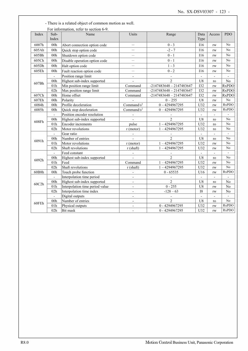
No. SX-DSV03307 - 123 -
R8.0 Motion Control Business Unit, Panasonic Corporation
- There is a related object of common motion as well.
For information, refer to section 6-9. Index Sub-
Index Name Units Range Data
Type Access PDO
6007h 00h Abort connection option code - 0 - 3 I16 rw No
605Ah 00h Quick stop option code - -2 - 7 I16 rw No
605Bh 00h Shutdown option code - 0 - 1 I16 rw No
605Ch 00h Disable operation option code - 0 - 1 I16 rw No
605Dh 00h Halt option code - 1 - 3 I16 rw No
605Eh 00h Fault reaction option code - 0 - 2 I16 rw No
607Bh
- Position range limit - - - - - 00h Highest sub-index supported - 2 U8 ro No 01h Min position range limit Command -2147483648 – 2147483647 I32 rw RxPDO 02h Max position range limit Command -2147483648 – 2147483647 I32 rw RxPDO
607Ch 00h Home offset Command -2147483648 – 2147483647 I32 rw RxPDO 607Eh 00h Polarity - 0 – 255 U8 rw No 6084h 00h Profile deceleration Command/s2 0 – 4294967295 U32 rw RxPDO 6085h 00h Quick stop deceleration Command/s2 0 – 4294967295 U32 rw RxPDO
608Fh
- Position encoder resolution - - - - - 00h Highest sub-index supported - 2 U8 ro No 01h Encoder increments pulse 1 – 4294967295 U32 ro No 02h Motor revolutions r (motor) 1 – 4294967295 U32 ro No
6091h
- Gear ratio - - - - - 00h Number of entries - 2 U8 ro No 01h Motor revolutions r (motor) 1 – 4294967295 U32 rw No 02h Shaft revolutions r (shaft) 1 – 4294967295 U32 rw No
6092h
- Feed constant - - - - - 00h Highest sub-index supported - 2 U8 ro No 01h Feed Command 1 – 4294967295 U32 rw No 02h Shaft revolutions r (shaft) 1 – 4294967295 U32 rw No
60B8h 00h Touch probe function - 0 - 65535 U16 rw RxPDO
60C2h
- Interpolation time period - - - - - 00h Highest sub-index supported - 2 U8 ro No 01h Interpolation time period value - 0 - 255 U8 rw No 02h Interpolation time index - -128 – 63 I8 rw No
60FEh
- Digital outputs - - - - - 00h Number of entries - 2 U8 ro No 01h Physical outputs - 0 - 4294967295 U32 rw RxPDO 02h Bit mask - 0 - 4294967295 U32 rw RxPDO
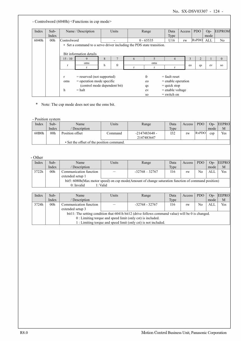
No. SX-DSV03307 - 124 -
R8.0 Motion Control Business Unit, Panasonic Corporation
- Controlword (6040h) <Functions in csp mode>
Index Sub-
Index Name / Description Units Range Data
Type Access PDO Op-
mode EEPROM
6040h 00h Controlword - 0 - 65535 U16 rw RxPDO ALL No • Set a command to a servo driver including the PDS state transition. Bit information details 15 - 10 9 8 7 6 5 4 3 2 1 0
r oms h fr oms eo qs ev so r r r r
r = reserved (not supported) fr = fault reset oms = operation mode specific eo = enable operation
(control mode dependent bit) qs = quick stop h = halt ev = enable voltage
so = switch on
* Note: The csp mode does not use the oms bit.
- Position system
Index Sub- Index
Name / Description
Units Range Data Type
Access PDO Op- mode
EEPROM
60B0h 00h Position offset Command -2147483648 - 2147483647
I32 rw RxPDO csp Yes
• Set the offset of the position command.
- Other
Index Sub- Index
Name / Description
Units Range Data Type
Access PDO Op- mode
EEPROM
3722h 00h Communication function extended setup 1
- -32768 – 32767 I16 rw No ALL Yes
bit5: 6080h(Max motor speed) on csp mode(Amount of change saturation function of command position) 0: Invalid 1: Valid
Index Sub-
Index Name
/ Description Units Range Data
Type Access PDO Op-
mode EEPRO
M 3724h 00h Communication function
extended setup 3 - -32768 - 32767 I16 rw No ALL Yes
bit11: The setting condition that 6041h bit12 (drive follows command value) will be 0 is changed. 0 : Limiting torque and speed limit (only cst) is included. 1 : Limiting torque and speed limit (only cst) is not included.
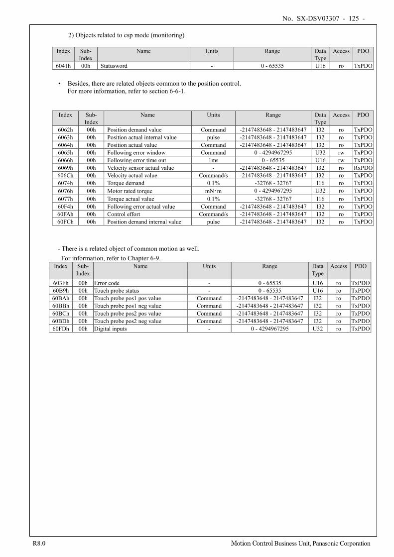
No. SX-DSV03307 - 125 -
R8.0 Motion Control Business Unit, Panasonic Corporation
2) Objects related to csp mode (monitoring)
Index Sub-
Index Name Units Range Data
Type Access PDO
6041h 00h Statusword - 0 - 65535 U16 ro TxPDO
• Besides, there are related objects common to the position control. For more information, refer to section 6-6-1.
Index Sub- Index
Name Units Range Data Type
Access PDO
6062h 00h Position demand value Command -2147483648 - 2147483647 I32 ro TxPDO 6063h 00h Position actual internal value pulse -2147483648 - 2147483647 I32 ro TxPDO 6064h 00h Position actual value Command -2147483648 - 2147483647 I32 ro TxPDO 6065h 00h Following error window Command 0 - 4294967295 U32 rw TxPDO 6066h 00h Following error time out 1ms 0 - 65535 U16 rw TxPDO 6069h 00h Velocity sensor actual value - -2147483648 - 2147483647 I32 ro RxPDO 606Ch 00h Velocity actual value Command/s -2147483648 - 2147483647 I32 ro TxPDO 6074h 00h Torque demand 0.1% -32768 - 32767 I16 ro TxPDO 6076h 00h Motor rated torque mN・m 0 - 4294967295 U32 ro TxPDO 6077h 00h Torque actual value 0.1% -32768 - 32767 I16 ro TxPDO 60F4h 00h Following error actual value Command -2147483648 - 2147483647 I32 ro TxPDO 60FAh 00h Control effort Command/s -2147483648 - 2147483647 I32 ro TxPDO 60FCh 00h Position demand internal value pulse -2147483648 - 2147483647 I32 ro TxPDO
- There is a related object of common motion as well. For information, refer to Chapter 6-9.
Index Sub- Index
Name Units Range Data Type
Access PDO
603Fh 00h Error code - 0 - 65535 U16 ro TxPDO 60B9h 00h Touch probe status - 0 - 65535 U16 ro TxPDO 60BAh 00h Touch probe pos1 pos value Command -2147483648 - 2147483647 I32 ro TxPDO 60BBh 00h Touch probe pos1 neg value Command -2147483648 - 2147483647 I32 ro TxPDO 60BCh 00h Touch probe pos2 pos value Command -2147483648 - 2147483647 I32 ro TxPDO 60BDh 00h Touch probe pos2 neg value Command -2147483648 - 2147483647 I32 ro TxPDO 60FDh 00h Digital inputs - 0 - 4294967295 U32 ro TxPDO
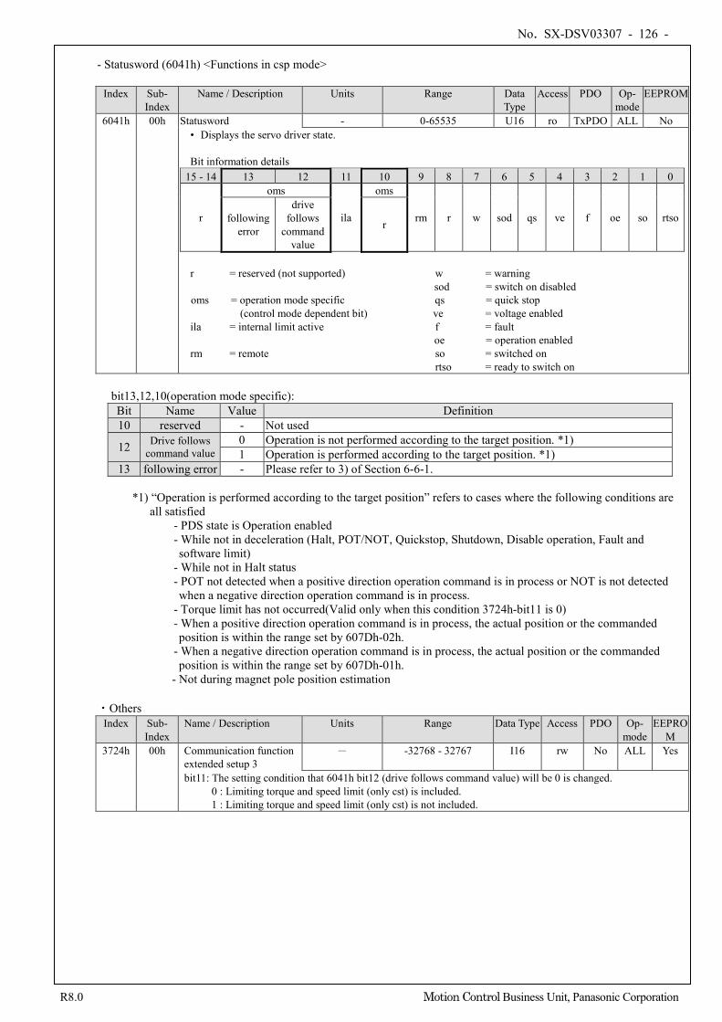
No. SX-DSV03307 - 126 -
R8.0 Motion Control Business Unit, Panasonic Corporation
- Statusword (6041h) <Functions in csp mode>
Index Sub-
Index Name / Description Units Range Data
Type Access PDO Op-
mode EEPROM
6041h 00h Statusword - 0-65535 U16 ro TxPDO ALL No • Displays the servo driver state. Bit information details
15 - 14 13 12 11 10 9 8 7 6 5 4 3 2 1 0
r
oms
ila
oms
rm r w sod qs ve f oe so rtso following error
drive follows
command value
r
r = reserved (not supported) w = warning
sod = switch on disabled oms = operation mode specific qs = quick stop (control mode dependent bit) ve = voltage enabled ila = internal limit active f = fault
oe = operation enabled rm = remote so = switched on
rtso = ready to switch on
bit13,12,10(operation mode specific): Bit Name Value Definition 10 reserved - Not used
12 Drive follows command value
0 Operation is not performed according to the target position. *1) 1 Operation is performed according to the target position. *1)
13 following error - Please refer to 3) of Section 6-6-1.
*1) “Operation is performed according to the target position” refers to cases where the following conditions are all satisfied
- PDS state is Operation enabled - While not in deceleration (Halt, POT/NOT, Quickstop, Shutdown, Disable operation, Fault and software limit)
- While not in Halt status - POT not detected when a positive direction operation command is in process or NOT is not detected when a negative direction operation command is in process.
- Torque limit has not occurred(Valid only when this condition 3724h-bit11 is 0) - When a positive direction operation command is in process, the actual position or the commanded position is within the range set by 607Dh-02h.
- When a negative direction operation command is in process, the actual position or the commanded position is within the range set by 607Dh-01h.
- Not during magnet pole position estimation
・Others Index Sub-
Index Name / Description Units Range Data Type Access PDO Op-
mode EEPRO
M 3724h 00h Communication function
extended setup 3 - -32768 - 32767 I16 rw No ALL Yes
bit11: The setting condition that 6041h bit12 (drive follows command value) will be 0 is changed. 0 : Limiting torque and speed limit (only cst) is included. 1 : Limiting torque and speed limit (only cst) is not included.
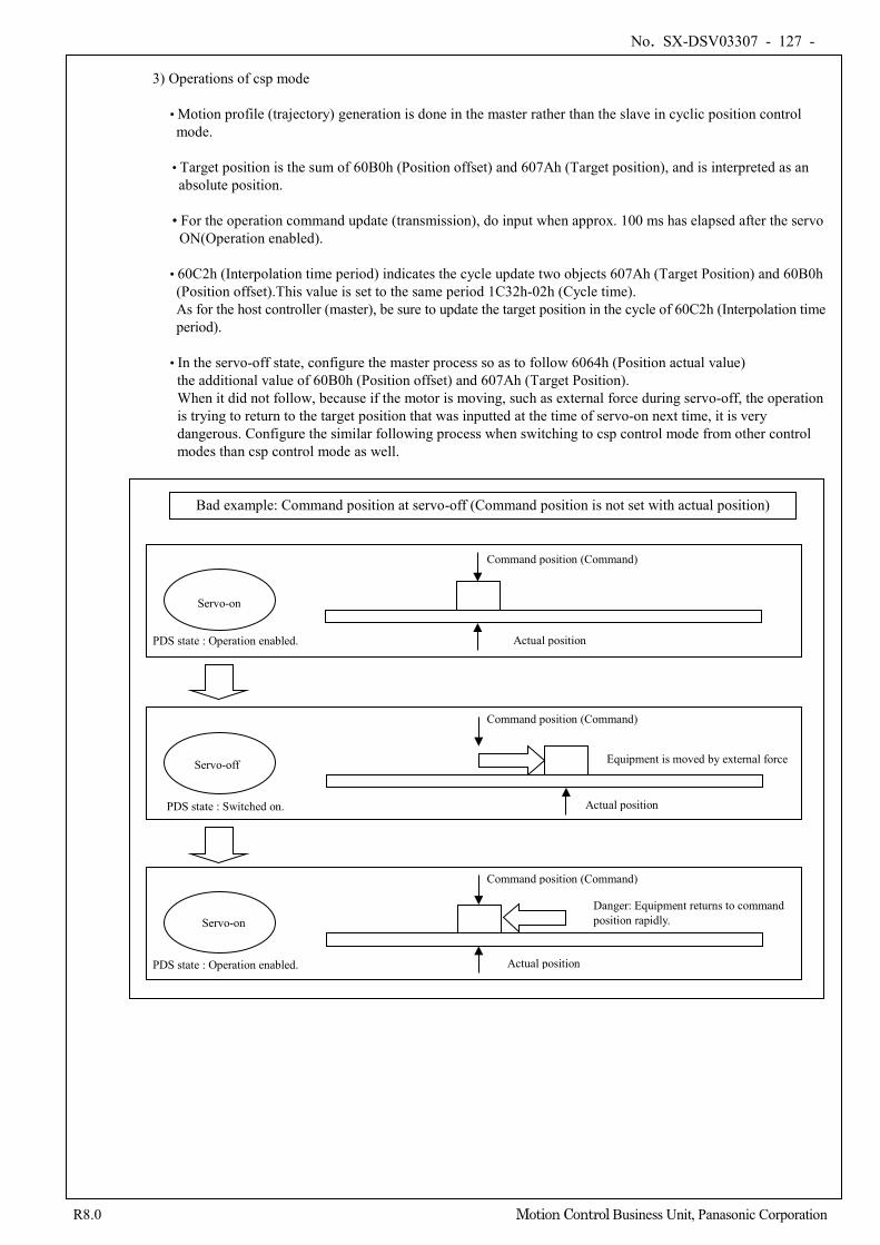
No. SX-DSV03307 - 127 -
R8.0 Motion Control Business Unit, Panasonic Corporation
3) Operations of csp mode
• Motion profile (trajectory) generation is done in the master rather than the slave in cyclic position control mode.
• Target position is the sum of 60B0h (Position offset) and 607Ah (Target position), and is interpreted as an absolute position.
• For the operation command update (transmission), do input when approx. 100 ms has elapsed after the servo ON(Operation enabled).
• 60C2h (Interpolation time period) indicates the cycle update two objects 607Ah (Target Position) and 60B0h (Position offset).This value is set to the same period 1C32h-02h (Cycle time). As for the host controller (master), be sure to update the target position in the cycle of 60C2h (Interpolation time period).
• In the servo-off state, configure the master process so as to follow 6064h (Position actual value) the additional value of 60B0h (Position offset) and 607Ah (Target Position). When it did not follow, because if the motor is moving, such as external force during servo-off, the operation is trying to return to the target position that was inputted at the time of servo-on next time, it is very dangerous. Configure the similar following process when switching to csp control mode from other control modes than csp control mode as well.
Command position (Command)
Actual position
Actual position
Actual position
Servo-on
Servo-off
Servo-on
PDS state : Operation enabled.
PDS state : Switched on.
PDS state : Operation enabled.
Bad example: Command position at servo-off (Command position is not set with actual position)
Command position (Command)
Command position (Command)
Equipment is moved by external force
Danger: Equipment returns to command position rapidly.
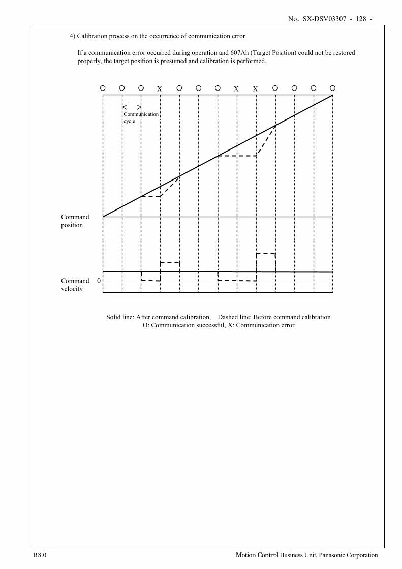
No. SX-DSV03307 - 128 -
R8.0 Motion Control Business Unit, Panasonic Corporation
4) Calibration process on the occurrence of communication error
If a communication error occurred during operation and 607Ah (Target Position) could not be restored properly, the target position is presumed and calibration is performed.
Solid line: After command calibration, Dashed line: Before command calibration O: Communication successful, X: Communication error
X X X
Command velocity
Command position
Communication cycle
0
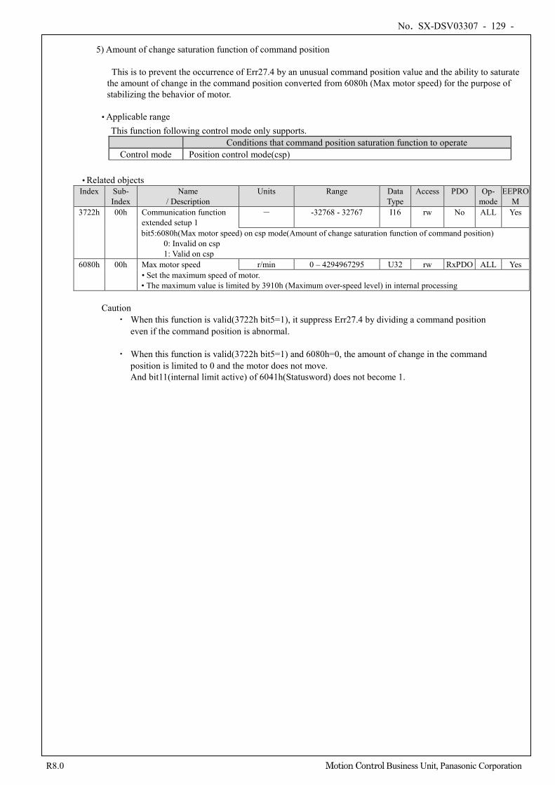
No. SX-DSV03307 - 129 -
R8.0 Motion Control Business Unit, Panasonic Corporation
5) Amount of change saturation function of command position
This is to prevent the occurrence of Err27.4 by an unusual command position value and the ability to saturate
the amount of change in the command position converted from 6080h (Max motor speed) for the purpose of stabilizing the behavior of motor.
• Applicable range
This function following control mode only supports. Conditions that command position saturation function to operate
Control mode Position control mode(csp)
• Related objects Index Sub-
Index Name
/ Description Units Range Data
Type Access PDO Op-
mode EEPRO
M 3722h 00h Communication function
extended setup 1 - -32768 - 32767 I16 rw No ALL Yes
bit5:6080h(Max motor speed) on csp mode(Amount of change saturation function of command position) 0: Invalid on csp 1: Valid on csp
6080h 00h Max motor speed r/min 0 – 4294967295 U32 rw RxPDO ALL Yes • Set the maximum speed of motor. • The maximum value is limited by 3910h (Maximum over-speed level) in internal processing
Caution
・ When this function is valid(3722h bit5=1), it suppress Err27.4 by dividing a command position even if the command position is abnormal.
・ When this function is valid(3722h bit5=1) and 6080h=0, the amount of change in the command position is limited to 0 and the motor does not move. And bit11(internal limit active) of 6041h(Statusword) does not become 1.
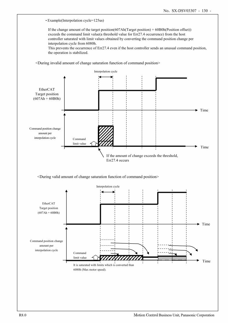
No. SX-DSV03307 - 130 -
R8.0 Motion Control Business Unit, Panasonic Corporation
• Example(Interpolation cycle=125us)
If the change amount of the target position(607Ah(Target position) + 60B0h(Position offset)) exceeds the command limit value(a threshold value for Err27.4 occurrence) from the host controller saturated with limit values obtained by converting the command position change per interpolation cycle from 6080h. This prevents the occurrence of Err27.4 even if the host controller sends an unusual command position, the operation is stabilized.
<During invalid amount of change saturation function of command position>
Time
EtherCAT Target position
(607Ah + 60B0h)
Time
Command position change amount per
interpolation cycle Command limit value
Interpolation cycle
If the amount of change exceeds the threshold, Err27.4 occurs
<During valid amount of change saturation function of command position>
Time
EtherCAT Target position
(607Ah + 60B0h)
Time
It is saturated with limits which is converted than 6080h (Max motor speed).
Command position change amount per
interpolation cycle Command limit value
Interpolation cycle
No. SX-DSV03307 - 131 -
R8.0 Motion Control Business Unit, Panasonic Corporation
6-6-4 Interpolating Position Mode (ip mode) (Not supported)
This mode is not supported by this software version. Do not set 6060h (Modes of operation) to 7.
It is a position control mode to operate by creating a command position in the host controller (master) and updating the command position buffered by buffering it to the servo driver inside in the communication cycle in an interpolation time.
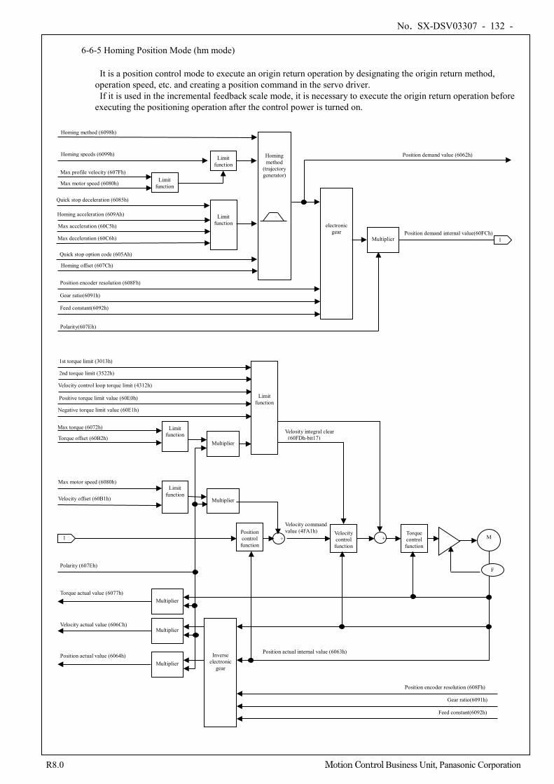
No. SX-DSV03307 - 132 -
R8.0 Motion Control Business Unit, Panasonic Corporation
6-6-5 Homing Position Mode (hm mode)
It is a position control mode to execute an origin return operation by designating the origin return method, operation speed, etc. and creating a position command in the servo driver.
If it is used in the incremental feedback scale mode, it is necessary to execute the origin return operation before executing the positioning operation after the control power is turned on.
+
Multiplier
Position demand value (6062h)
electronic gear
Feed constant(6092h)
Gear ratio(6091h)
Position encoder resolution (608Fh)
Position demand internal value(60FCh) 1
1 Position control function
Velocity control function
+ Torque control
function M
F
Feed constant(6092h)
Gear ratio(6091h)
Position encoder resolution (608Fh)
Position actual value (6064h)
Velocity actual value (606Ch)
Torque actual value (6077h)
Polarity (607Eh)
Position actual internal value (6063h)
1st torque limit (3013h)
Max torque (6072h)
Torque offset (60B2h)
Max motor speed (6080h)
Velocity offset (60B1h)
Multiplier
Multiplier
Multiplier
Multiplier
Multiplier
Limit function
Limit function
Inverse electronic
gear
Polarity(607Eh)
Limit function
Homing method (6098h)
Homing speeds (6099h)
Homing acceleration (609Ah)
Homing offset (607Ch)
Max profile velocity (607Fh)
Limit function
Homing method
(trajectory generator)
Limit function Max acceleration (60C5h)
Max deceleration (60C6h)
Quick stop option code (605Ah)
Quick stop deceleration (6085h)
Limit function Max motor speed (6080h)
Velocity command value (4FA1h)
Positive torque limit value (60E0h)
Negative torque limit value (60E1h)
2nd torque limit (3522h) Velocity control loop torque limit (4312h)
Velosity integral clear (60FDh-bit17)
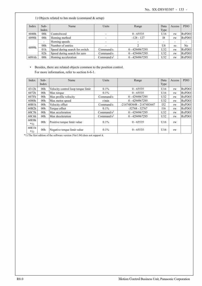
No. SX-DSV03307 - 133 -
R8.0 Motion Control Business Unit, Panasonic Corporation
1) Objects related to hm mode (command & setup)
Index Sub-
Index Name Units Range Data
Type Access PDO
6040h 00h Controlword - 0 - 65535 U16 rw RxPDO 6098h 00h Homing method - -128 - 127 I8 rw RxPDO
6099h
- Homing speeds - - - - - 00h Number of entries - 2 U8 ro No 01h Speed during search for switch Command/s 0 - 4294967295 U32 rw RxPDO 02h Speed during search for zero Command/s 0 - 4294967295 U32 rw RxPDO
609Ah 00h Homing acceleration Command/s2 0 - 4294967295 U32 rw RxPDO • Besides, there are related objects common to the position control.
For more information, refer to section 6-6-1.
Index Sub- Index
Name Units Range Data Type
Access PDO
4312h 00h Velocity control loop torque limit 0.1% 0 - 65535 U16 rw RxPDO 6072h 00h Max torque 0.1% 0 - 65535 U16 rw RxPDO 607Fh 00h Max profile velocity Command/s 0 - 4294967295 U32 rw RxPDO 6080h 00h Max motor speed r/min 0 - 4294967295 U32 rw RxPDO 60B1h 00h Velocity offset Command/s -2147483648 - 2147483647 I32 rw RxPDO 60B2h 00h Torque offset 0.1% -32768 - 32767 I16 rw RxPDO 60C5h 00h Max acceleration Command/s2 0 - 4294967295 U32 rw RxPDO 60C6h 00h Max deceleration Command/s2 0 - 4294967295 U32 rw RxPDO 60E0h
*1) 00h Positive torque limit value 0.1% 0 - 65535 U16 rw
60E1h *1) 00h Negative torque limit value 0.1% 0 - 65535 U16 rw
*1) The first edition of the software version (Ver1.04) does not support it.
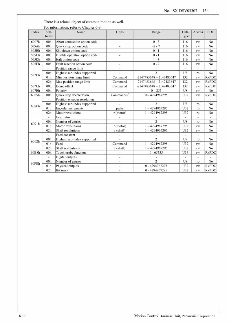
No. SX-DSV03307 - 134 -
R8.0 Motion Control Business Unit, Panasonic Corporation
- There is a related object of common motion as well.
For information, refer to Chapter 6-9. Index Sub-
Index Name Units Range Data
Type Access PDO
6007h 00h Abort connection option code - 0 - 3 I16 rw No 605Ah 00h Quick stop option code - -2 - 7 I16 rw No 605Bh 00h Shutdown option code - 0 - 1 I16 rw No 605Ch 00h Disable operation option code - 0 - 1 I16 rw No 605Dh 00h Halt option code - 1 - 3 I16 rw No 605Eh 00h Fault reaction option code - 0 - 2 I16 rw No
607Bh
- Position range limit - - - - - 00h Highest sub-index supported - 2 U8 ro No 01h Min position range limit Command -2147483648 – 2147483647 I32 rw RxPDO 02h Max position range limit Command -2147483648 – 2147483647 I32 rw RxPDO
607Ch 00h Home offset Command -2147483648 – 2147483647 I32 rw RxPDO 607Eh 00h Polarity - 0 – 255 U8 rw No 6085h 00h Quick stop deceleration Command/s2 0 – 4294967295 U32 rw RxPDO
608Fh
- Position encoder resolution - - - - - 00h Highest sub-index supported - 2 U8 ro No 01h Encoder increments pulse 1 – 4294967295 U32 ro No 02h Motor revolutions r (motor) 1 – 4294967295 U32 ro No
6091h
- Gear ratio - - - - - 00h Number of entries - 2 U8 ro No 01h Motor revolutions r (motor) 1 – 4294967295 U32 rw No 02h Shaft revolutions r (shaft) 1 – 4294967295 U32 rw No
6092h
- Feed constant - - - - - 00h Highest sub-index supported - 2 U8 ro No 01h Feed Command 1 – 4294967295 U32 rw No 02h Shaft revolutions r (shaft) 1 – 4294967295 U32 rw No
60B8h 00h Touch probe function - 0 - 65535 U16 rw RxPDO
60FEh
- Digital outputs - - - - - 00h Number of entries - 2 U8 ro No 01h Physical outputs - 0 - 4294967295 U32 rw RxPDO 02h Bit mask - 0 - 4294967295 U32 rw RxPDO
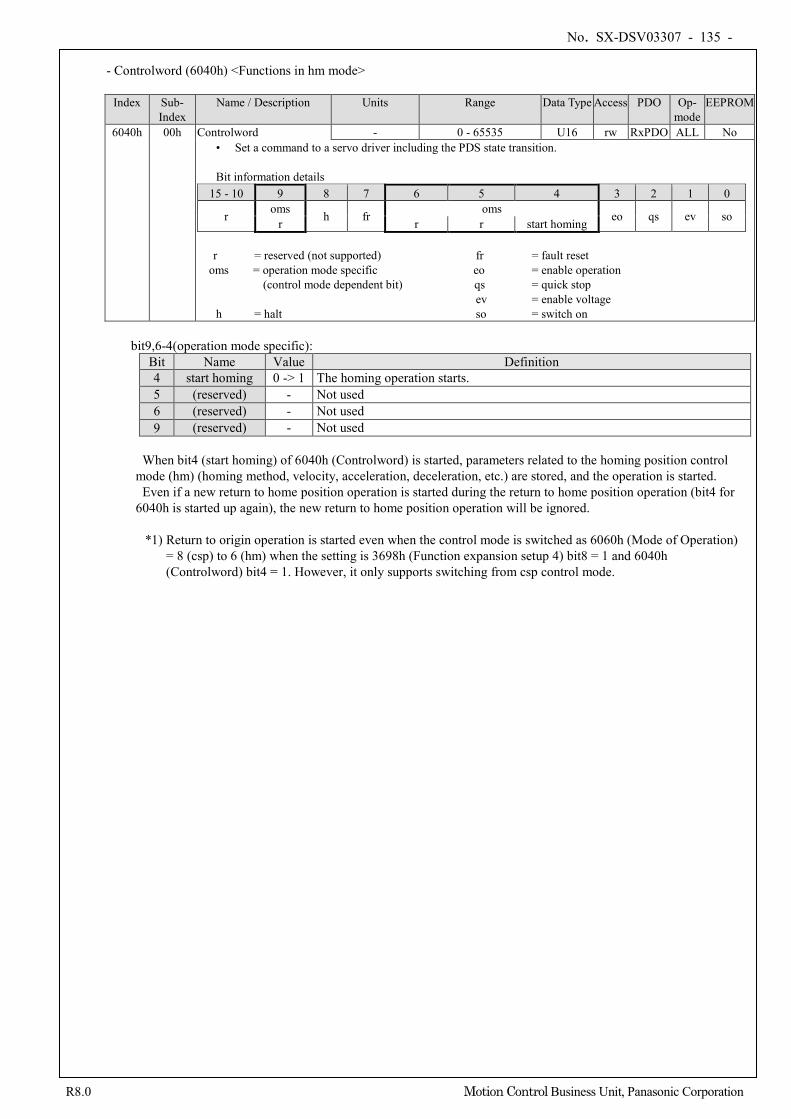
No. SX-DSV03307 - 135 -
R8.0 Motion Control Business Unit, Panasonic Corporation
- Controlword (6040h) <Functions in hm mode>
Index Sub-
Index Name / Description Units Range Data Type Access PDO Op-
mode EEPROM
6040h 00h Controlword - 0 - 65535 U16 rw RxPDO ALL No • Set a command to a servo driver including the PDS state transition.
Bit information details
15 - 10 9 8 7 6 5 4 3 2 1 0
r oms h fr oms eo qs ev so r r r start homing
r = reserved (not supported) fr = fault reset oms = operation mode specific eo = enable operation
(control mode dependent bit) qs = quick stop ev = enable voltage
h = halt so = switch on
bit9,6-4(operation mode specific): Bit Name Value Definition 4 start homing 0 -> 1 The homing operation starts. 5 (reserved) - Not used 6 (reserved) - Not used 9 (reserved) - Not used
When bit4 (start homing) of 6040h (Controlword) is started, parameters related to the homing position control
mode (hm) (homing method, velocity, acceleration, deceleration, etc.) are stored, and the operation is started. Even if a new return to home position operation is started during the return to home position operation (bit4 for
6040h is started up again), the new return to home position operation will be ignored.
*1) Return to origin operation is started even when the control mode is switched as 6060h (Mode of Operation) = 8 (csp) to 6 (hm) when the setting is 3698h (Function expansion setup 4) bit8 = 1 and 6040h (Controlword) bit4 = 1. However, it only supports switching from csp control mode.
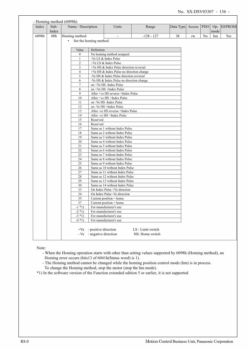
No. SX-DSV03307 - 136 -
R8.0 Motion Control Business Unit, Panasonic Corporation
- Homing method (6098h) Index Sub-
Index Name / Description Units Range Data Type Access PDO Op-
mode EEPROM
6098h 00h Homing method - -128 - 127 I8 rw No hm Yes • Set the homing method.
Value Definition
0 No homing method assigned 1 -Ve LS & Index Pulse 2 +Ve LS & Index Pulse 3 +Ve HS & Index Pulse direction reversal 4 +Ve HS & Index Pulse no direction change 5 -Ve HS & Index Pulse direction reversal 6 -Ve HS & Index Pulse no direction change 7 on +Ve HS -Index Pulse 8 on +Ve HS +Index Pulse 9 After +ve HS reverse +Index Pulse
10 After +ve HS +Index Pulse 11 on -Ve HS -Index Pulse 12 on -Ve HS +Index Pulse 13 After -ve HS reverse +Index Pulse 14 After -ve HS +Index Pulse 15 Reserved 16 Reserved 17 Same as 1 without Index Pulse 18 Same as 2 without Index Pulse 19 Same as 3 without Index Pulse 20 Same as 4 without Index Pulse 21 Same as 5 without Index Pulse 22 Same as 6 without Index Pulse 23 Same as 7 without Index Pulse 24 Same as 8 without Index Pulse 25 Same as 9 without Index Pulse 26 Same as 10 without Index Pulse 27 Same as 11 without Index Pulse 28 Same as 12 without Index Pulse 29 Same as 13 without Index Pulse 30 Same as 14 without Index Pulse 33 On Index Pulse +Ve direction 34 On Index Pulse -Ve direction 35 Current position = home 37 Current position = home
-1 *1) For manufacturer's use -2 *1) For manufacturer's use -3 *1) For manufacturer's use -4 *1) For manufacturer's use
+Ve : positive direction LS : Limit switch - Ve : negative direction HS: Home switch
Note:
- When the Homing operation starts with other than setting values supported by 6098h (Homing method), an Homing error occurs (bits13 of 6041h(Status word) is 1).
- The Homing method cannot be changed while the homing position control mode (hm) is in process. To change the Homing method, stop the motor (stop the hm mode).
*1) In the software version of the Function extended edition 5 or earlier, it is not supported
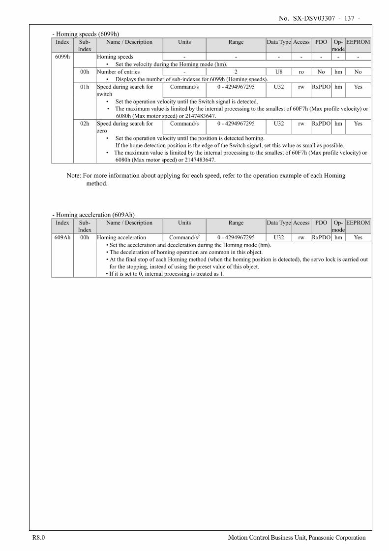
No. SX-DSV03307 - 137 -
R8.0 Motion Control Business Unit, Panasonic Corporation
- Homing speeds (6099h) Index Sub-
Index Name / Description Units Range Data Type Access PDO Op-
mode EEPROM
6099h Homing speeds - - - - - - - • Set the velocity during the Homing mode (hm).
00h Number of entries - 2 U8 ro No hm No • Displays the number of sub-indexes for 6099h (Homing speeds).
01h Speed during search for switch
Command/s 0 - 4294967295 U32 rw RxPDO hm Yes
• Set the operation velocity until the Switch signal is detected. • The maximum value is limited by the internal processing to the smallest of 60F7h (Max profile velocity) or
6080h (Max motor speed) or 2147483647. 02h Speed during search for
zero Command/s 0 - 4294967295 U32 rw RxPDO hm Yes
• Set the operation velocity until the position is detected homing. If the home detection position is the edge of the Switch signal, set this value as small as possible.
• The maximum value is limited by the internal processing to the smallest of 60F7h (Max profile velocity) or 6080h (Max motor speed) or 2147483647.
Note: For more information about applying for each speed, refer to the operation example of each Homing
method.
- Homing acceleration (609Ah) Index Sub-
Index Name / Description Units Range Data Type Access PDO Op-
mode EEPROM
609Ah 00h Homing acceleration Command/s2 0 - 4294967295 U32 rw RxPDO hm Yes • Set the acceleration and deceleration during the Homing mode (hm). • The deceleration of homing operation are common in this object. • At the final stop of each Homing method (when the homing position is detected), the servo lock is carried out
for the stopping, instead of using the preset value of this object. • If it is set to 0, internal processing is treated as 1.
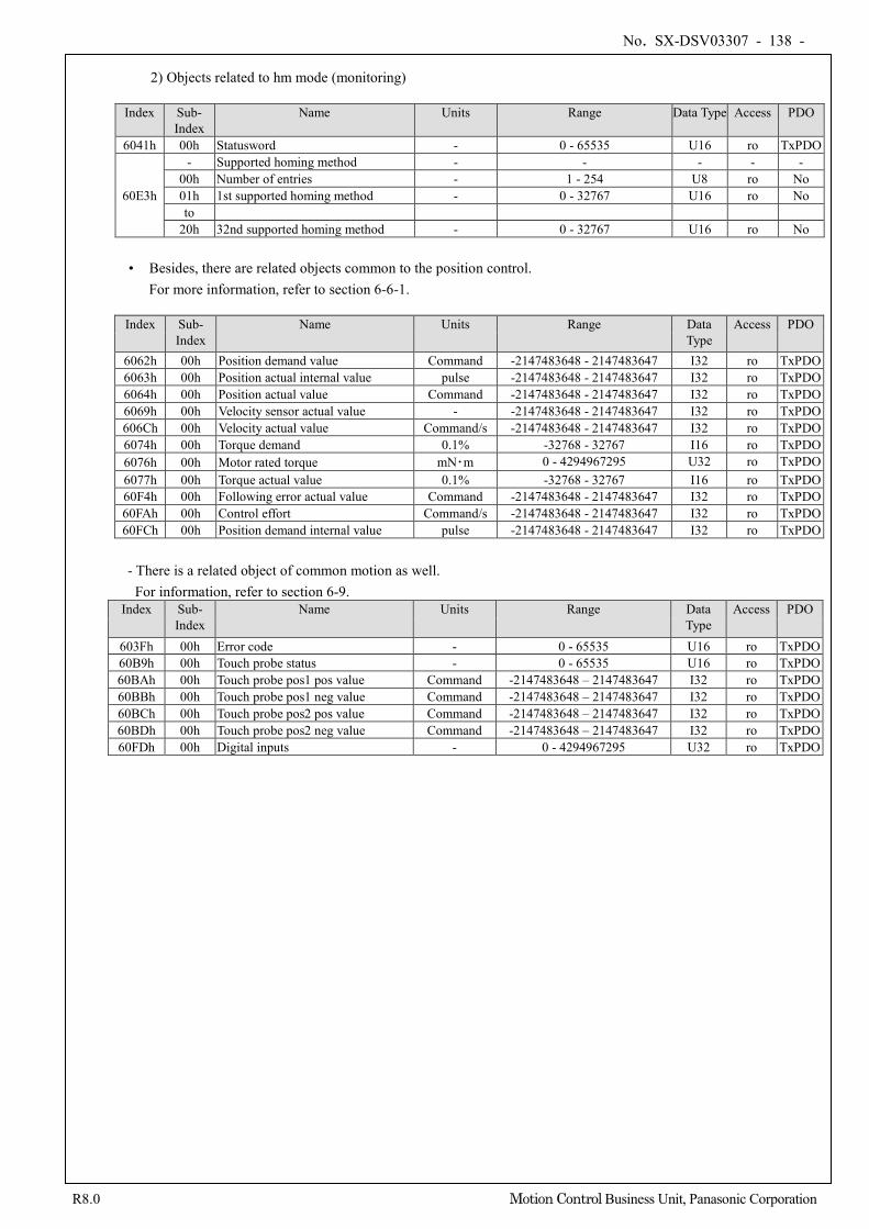
No. SX-DSV03307 - 138 -
R8.0 Motion Control Business Unit, Panasonic Corporation
2) Objects related to hm mode (monitoring)
Index Sub-
Index Name Units Range Data Type Access PDO
6041h 00h Statusword - 0 - 65535 U16 ro TxPDO
60E3h
- Supported homing method - - - - - 00h Number of entries - 1 - 254 U8 ro No 01h 1st supported homing method - 0 - 32767 U16 ro No to
20h 32nd supported homing method - 0 - 32767 U16 ro No
• Besides, there are related objects common to the position control. For more information, refer to section 6-6-1.
Index Sub-
Index Name Units Range Data
Type Access PDO
6062h 00h Position demand value Command -2147483648 - 2147483647 I32 ro TxPDO 6063h 00h Position actual internal value pulse -2147483648 - 2147483647 I32 ro TxPDO 6064h 00h Position actual value Command -2147483648 - 2147483647 I32 ro TxPDO 6069h 00h Velocity sensor actual value - -2147483648 - 2147483647 I32 ro TxPDO 606Ch 00h Velocity actual value Command/s -2147483648 - 2147483647 I32 ro TxPDO 6074h 00h Torque demand 0.1% -32768 - 32767 I16 ro TxPDO 6076h 00h Motor rated torque mN・m 0 - 4294967295 U32 ro TxPDO 6077h 00h Torque actual value 0.1% -32768 - 32767 I16 ro TxPDO 60F4h 00h Following error actual value Command -2147483648 - 2147483647 I32 ro TxPDO 60FAh 00h Control effort Command/s -2147483648 - 2147483647 I32 ro TxPDO 60FCh 00h Position demand internal value pulse -2147483648 - 2147483647 I32 ro TxPDO
- There is a related object of common motion as well.
For information, refer to section 6-9. Index Sub-
Index Name Units Range Data
Type Access PDO
603Fh 00h Error code - 0 - 65535 U16 ro TxPDO 60B9h 00h Touch probe status - 0 - 65535 U16 ro TxPDO 60BAh 00h Touch probe pos1 pos value Command -2147483648 – 2147483647 I32 ro TxPDO 60BBh 00h Touch probe pos1 neg value Command -2147483648 – 2147483647 I32 ro TxPDO 60BCh 00h Touch probe pos2 pos value Command -2147483648 – 2147483647 I32 ro TxPDO 60BDh 00h Touch probe pos2 neg value Command -2147483648 – 2147483647 I32 ro TxPDO 60FDh 00h Digital inputs - 0 - 4294967295 U32 ro TxPDO
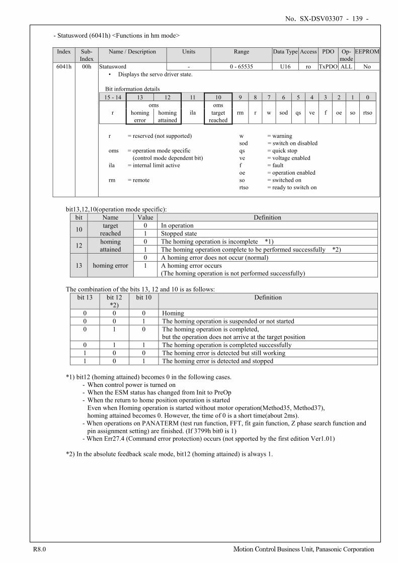
No. SX-DSV03307 - 139 -
R8.0 Motion Control Business Unit, Panasonic Corporation
- Statusword (6041h) <Functions in hm mode>
Index Sub-
Index Name / Description Units Range Data Type Access PDO Op-
mode EEPROM
6041h 00h Statusword - 0 - 65535 U16 ro TxPDO ALL No • Displays the servo driver state.
Bit information details 15 - 14 13 12 11 10 9 8 7 6 5 4 3 2 1 0
r oms
ila oms
rm r w sod qs ve f oe so rtso homing error
homing attained
target reached
r = reserved (not supported) w = warning
sod = switch on disabled oms = operation mode specific qs = quick stop
(control mode dependent bit) ve = voltage enabled ila = internal limit active f = fault
oe = operation enabled rm = remote so = switched on
rtso = ready to switch on
bit13,12,10(operation mode specific):
bit Name Value Definition
10 target reached
0 In operation 1 Stopped state
12 homing attained
0 The homing operation is incomplete *1) 1 The homing operation complete to be performed successfully *2)
13 homing error 0 A homing error does not occur (normal) 1 A homing error occurs
(The homing operation is not performed successfully)
The combination of the bits 13, 12 and 10 is as follows: bit 13 bit 12
*2) bit 10 Definition
0 0 0 Homing 0 0 1 The homing operation is suspended or not started 0 1 0 The homing operation is completed,
but the operation does not arrive at the target position 0 1 1 The homing operation is completed successfully 1 0 0 The homing error is detected but still working 1 0 1 The homing error is detected and stopped
*1) bit12 (homing attained) becomes 0 in the following cases.
- When control power is turned on - When the ESM status has changed from Init to PreOp - When the return to home position operation is started
Even when Homing operation is started without motor operation(Method35, Method37), homing attained becomes 0. However, the time of 0 is a short time(about 2ms).
- When operations on PANATERM (test run function, FFT, fit gain function, Z phase search function and pin assignment setting) are finished. (If 3799h bit0 is 1)
- When Err27.4 (Command error protection) occurs (not spported by the first edition Ver1.01)
*2) In the absolute feedback scale mode, bit12 (homing attained) is always 1.
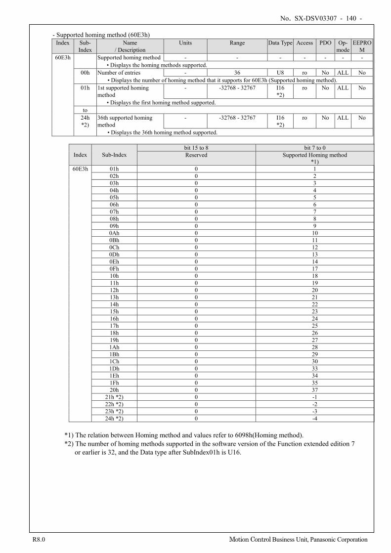
No. SX-DSV03307 - 140 -
R8.0 Motion Control Business Unit, Panasonic Corporation
- Supported homing method (60E3h)
Index Sub- Index
Name / Description
Units Range Data Type Access PDO Op- mode
EEPROM
60E3h Supported homing method - - - - - - - • Displays the homing methods supported.
00h Number of entries - 36 U8 ro No ALL No • Displays the number of homing method that it supports for 60E3h (Supported homing method).
01h 1st supported homing method
- -32768 - 32767 I16 *2)
ro No ALL No
• Displays the first homing method supported. to
24h *2)
36th supported homing method
- -32768 - 32767 I16 *2)
ro No ALL No
• Displays the 36th homing method supported.
Index Sub-Index bit 15 to 8 bit 7 to 0 Reserved Supported Homing method
*1) 60E3h 01h 0 1
02h 0 2 03h 0 3 04h 0 4 05h 0 5 06h 0 6 07h 0 7 08h 0 8 09h 0 9 0Ah 0 10 0Bh 0 11 0Ch 0 12 0Dh 0 13 0Eh 0 14 0Fh 0 17 10h 0 18 11h 0 19 12h 0 20 13h 0 21 14h 0 22 15h 0 23 16h 0 24 17h 0 25 18h 0 26 19h 0 27 1Ah 0 28 1Bh 0 29 1Ch 0 30 1Dh 0 33 1Eh 0 34 1Fh 0 35 20h 0 37
21h *2) 0 -1 22h *2) 0 -2 23h *2) 0 -3 24h *2) 0 -4
*1) The relation between Homing method and values refer to 6098h(Homing method). *2) The number of homing methods supported in the software version of the Function extended edition 7
or earlier is 32, and the Data type after SubIndex01h is U16.
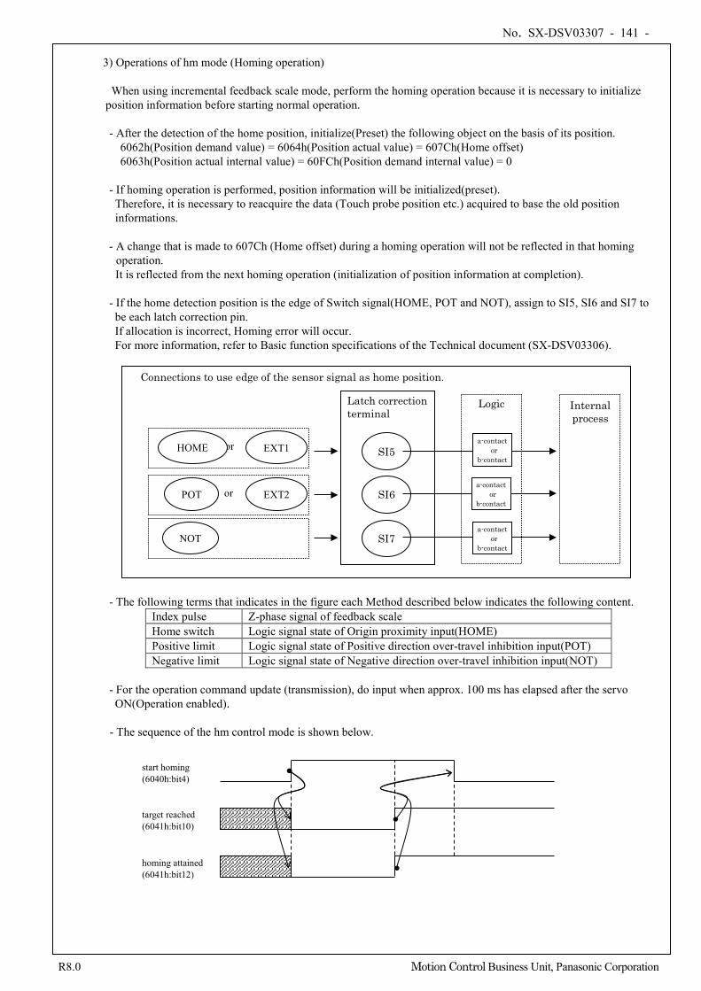
No. SX-DSV03307 - 141 -
R8.0 Motion Control Business Unit, Panasonic Corporation
3) Operations of hm mode (Homing operation)
When using incremental feedback scale mode, perform the homing operation because it is necessary to initialize
position information before starting normal operation.
- After the detection of the home position, initialize(Preset) the following object on the basis of its position. 6062h(Position demand value) = 6064h(Position actual value) = 607Ch(Home offset) 6063h(Position actual internal value) = 60FCh(Position demand internal value) = 0
- If homing operation is performed, position information will be initialized(preset).
Therefore, it is necessary to reacquire the data (Touch probe position etc.) acquired to base the old position informations.
- A change that is made to 607Ch (Home offset) during a homing operation will not be reflected in that homing
operation. It is reflected from the next homing operation (initialization of position information at completion).
- If the home detection position is the edge of Switch signal(HOME, POT and NOT), assign to SI5, SI6 and SI7 to be each latch correction pin. If allocation is incorrect, Homing error will occur. For more information, refer to Basic function specifications of the Technical document (SX-DSV03306).
- The following terms that indicates in the figure each Method described below indicates the following content. Index pulse Z-phase signal of feedback scale Home switch Logic signal state of Origin proximity input(HOME) Positive limit Logic signal state of Positive direction over-travel inhibition input(POT) Negative limit Logic signal state of Negative direction over-travel inhibition input(NOT)
- For the operation command update (transmission), do input when approx. 100 ms has elapsed after the servo ON(Operation enabled).
- The sequence of the hm control mode is shown below.
Latch correction terminal
SI5
SI6
SI7
a-contact or
b-contact
Logic Internal process
Connections to use edge of the sensor signal as home position.
EXT1
EXT2
NOT
or
or HOME
POT a-contact
or b-contact
a-contact or
b-contact
start homing (6040h:bit4)
target reached (6041h:bit10)
homing attained (6041h:bit12)
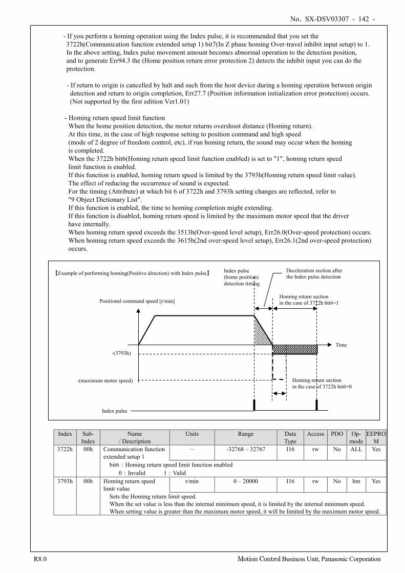
No. SX-DSV03307 - 142 -
R8.0 Motion Control Business Unit, Panasonic Corporation
- If you perform a homing operation using the Index pulse, it is recommended that you set the 3722h(Communication function extended setup 1) bit7(In Z phase homing Over-travel inhibit input setup) to 1. In the above setting, Index pulse movement amount becomes abnormal operation to the detection position, and to generate Err94.3 the (Home position return error protection 2) detects the inhibit input you can do the protection. - If return to origin is cancelled by halt and such from the host device during a homing operation between origin detection and return to origin completion, Err27.7 (Position information initialization error protection) occurs. (Not supported by the first edition Ver1.01)
- Homing return speed limit function
When the home position detection, the motor returns overshoot distance (Homing return). At this time, in the case of high response setting to position command and high speed (mode of 2 degree of freedom control, etc), if run homing return, the sound may occur when the homing is completed. When the 3722h bit6(Homing return speed limit function enabled) is set to "1", homing return speed limit function is enabled. If this function is enabled, homing return speed is limited by the 3793h(Homing return speed limit value). The effect of reducing the occurrence of sound is expected. For the timing (Attribute) at which bit 6 of 3722h and 3793h setting changes are reflected, refer to "9 Object Dictionary List". If this function is enabled, the time to homing completion might extending. If this function is disabled, homing return speed is limited by the maximum motor speed that the driver have internally. When homing return speed exceeds the 3513h(Over-speed level setup), Err26.0(Over-speed protection) occurs. When homing return speed exceeds the 3615h(2nd over-speed level setup), Err26.1(2nd over-speed protection) occurs.
Index Sub- Index
Name / Description
Units Range Data Type
Access PDO Op- mode
EEPROM
3722h 00h Communication function extended setup 1
- -32768 – 32767 I16 rw No ALL Yes
bit6:Homing return speed limit function enabled 0:Invalid 1:Valid
3793h 00h Homing return speed limit value
r/min 0 – 20000 I16 rw No hm Yes
Sets the Homing return limit speed. When the set value is less than the internal minimum speed, it is limited by the internal minimum speed. When setting value is greater than the maximum motor speed, it will be limited by the maximum motor speed.
Time
Homing return section in the case of 3722h bit6=0
Positional command speed [r/min]
Index pulse
-(3793h)
Index pulse (home position) detection timing
【Example of performing homing(Positive direction) with Index pulse】
Homing return section in the case of 3722h bit6=1
Deceleration section after the Index pulse detection
-(maximum motor speed)
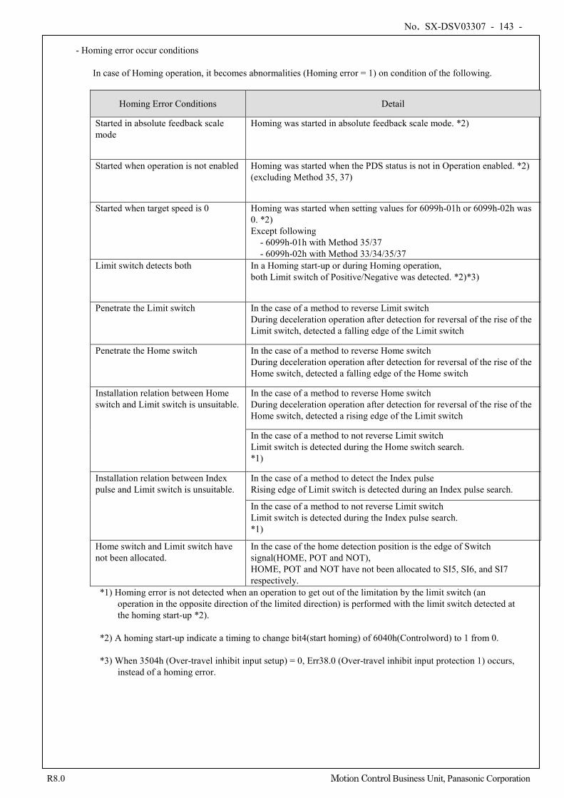
No. SX-DSV03307 - 143 -
R8.0 Motion Control Business Unit, Panasonic Corporation
- Homing error occur conditions
In case of Homing operation, it becomes abnormalities (Homing error = 1) on condition of the following.
Homing Error Conditions Detail
Started in absolute feedback scale mode
Homing was started in absolute feedback scale mode. *2)
Started when operation is not enabled Homing was started when the PDS status is not in Operation enabled. *2) (excluding Method 35, 37)
Started when target speed is 0 Homing was started when setting values for 6099h-01h or 6099h-02h was 0. *2) Except following
- 6099h-01h with Method 35/37 - 6099h-02h with Method 33/34/35/37
Limit switch detects both In a Homing start-up or during Homing operation, both Limit switch of Positive/Negative was detected. *2)*3)
Penetrate the Limit switch In the case of a method to reverse Limit switch During deceleration operation after detection for reversal of the rise of the Limit switch, detected a falling edge of the Limit switch
Penetrate the Home switch
In the case of a method to reverse Home switch During deceleration operation after detection for reversal of the rise of the Home switch, detected a falling edge of the Home switch
Installation relation between Home switch and Limit switch is unsuitable.
In the case of a method to reverse Home switch During deceleration operation after detection for reversal of the rise of the Home switch, detected a rising edge of the Limit switch
In the case of a method to not reverse Limit switch Limit switch is detected during the Home switch search. *1)
Installation relation between Index pulse and Limit switch is unsuitable.
In the case of a method to detect the Index pulse Rising edge of Limit switch is detected during an Index pulse search.
In the case of a method to not reverse Limit switch Limit switch is detected during the Index pulse search. *1)
Home switch and Limit switch have not been allocated.
In the case of the home detection position is the edge of Switch signal(HOME, POT and NOT), HOME, POT and NOT have not been allocated to SI5, SI6, and SI7 respectively.
*1) Homing error is not detected when an operation to get out of the limitation by the limit switch (an operation in the opposite direction of the limited direction) is performed with the limit switch detected at the homing start-up *2).
*2) A homing start-up indicate a timing to change bit4(start homing) of 6040h(Controlword) to 1 from 0. *3) When 3504h (Over-travel inhibit input setup) = 0, Err38.0 (Over-travel inhibit input protection 1) occurs,
instead of a homing error.
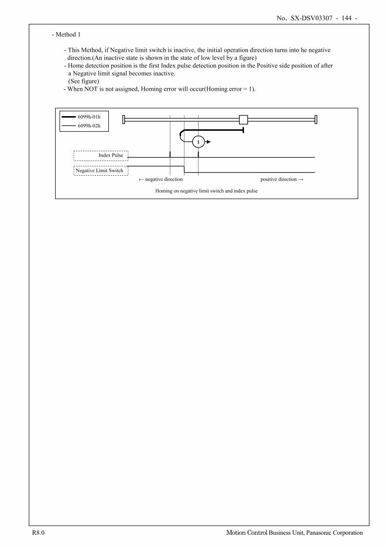
No. SX-DSV03307 - 144 -
R8.0 Motion Control Business Unit, Panasonic Corporation
- Method 1
- This Method, if Negative limit switch is inactive, the initial operation direction turns into he negative direction.(An inactive state is shown in the state of low level by a figure) - Home detection position is the first Index pulse detection position in the Positive side position of after
a Negative limit signal becomes inactive. (See figure)
- When NOT is not assigned, Homing error will occur(Homing error = 1).
Index Pulse
Negative Limit Switch
Homing on negative limit switch and index pulse
← negative direction positive direction →
1
6099h-01h
6099h-02h
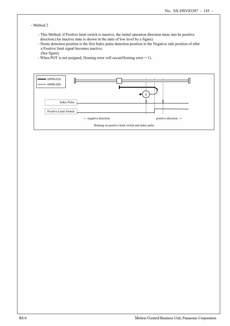
No. SX-DSV03307 - 145 -
R8.0 Motion Control Business Unit, Panasonic Corporation
- Method 2
- This Method, if Positive limit switch is inactive, the initial operation direction turns into he positive direction.(An inactive state is shown in the state of low level by a figure) - Home detection position is the first Index pulse detection position in the Negative side position of after
a Positive limit signal becomes inactive. (See figure)
- When POT is not assigned, Homing error will occur(Homing error = 1).
Index Pulse
Positive Limit Switch
Homing on positive limit switch and index pulse
← negative direction positive direction →
2
6099h-01h
6099h-02h
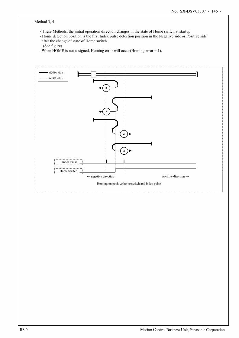
No. SX-DSV03307 - 146 -
R8.0 Motion Control Business Unit, Panasonic Corporation
- Method 3, 4
- These Methods, the initial operation direction changes in the state of Home switch at startup - Home detection position is the first Index pulse detection position in the Negative side or Positive side after the change of state of Home switch. (See figure)
- When HOME is not assigned, Homing error will occur(Homing error = 1).
Index Pulse
Home Switch
Homing on positive home switch and index pulse
← negative direction positive direction →
3
3
6099h-01h
6099h-02h
4
4
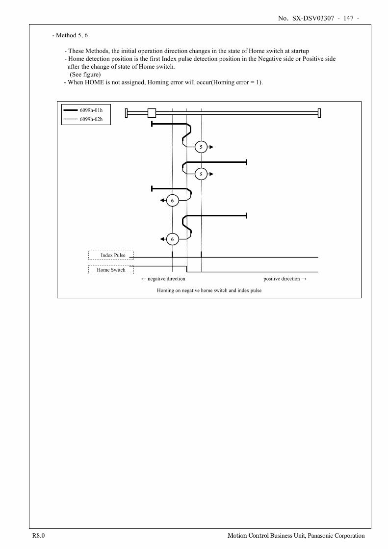
No. SX-DSV03307 - 147 -
R8.0 Motion Control Business Unit, Panasonic Corporation
- Method 5, 6
- These Methods, the initial operation direction changes in the state of Home switch at startup - Home detection position is the first Index pulse detection position in the Negative side or Positive side after the change of state of Home switch. (See figure)
- When HOME is not assigned, Homing error will occur(Homing error = 1).
Index Pulse
Home Switch
Homing on negative home switch and index pulse
← negative direction positive direction →
5
5
6099h-01h
6099h-02h
6
6
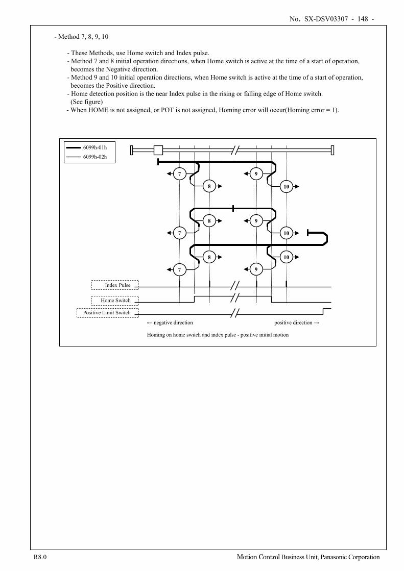
No. SX-DSV03307 - 148 -
R8.0 Motion Control Business Unit, Panasonic Corporation
- Method 7, 8, 9, 10
- These Methods, use Home switch and Index pulse. - Method 7 and 8 initial operation directions, when Home switch is active at the time of a start of operation, becomes the Negative direction. - Method 9 and 10 initial operation directions, when Home switch is active at the time of a start of operation, becomes the Positive direction. - Home detection position is the near Index pulse in the rising or falling edge of Home switch.
(See figure) - When HOME is not assigned, or POT is not assigned, Homing error will occur(Homing error = 1).
Index Pulse
Home Switch
Positive Limit Switch
Homing on home switch and index pulse - positive initial motion
← negative direction positive direction →
7
7
7
6099h-01h
6099h-02h
8
8
8
9
9
9
10
10
10
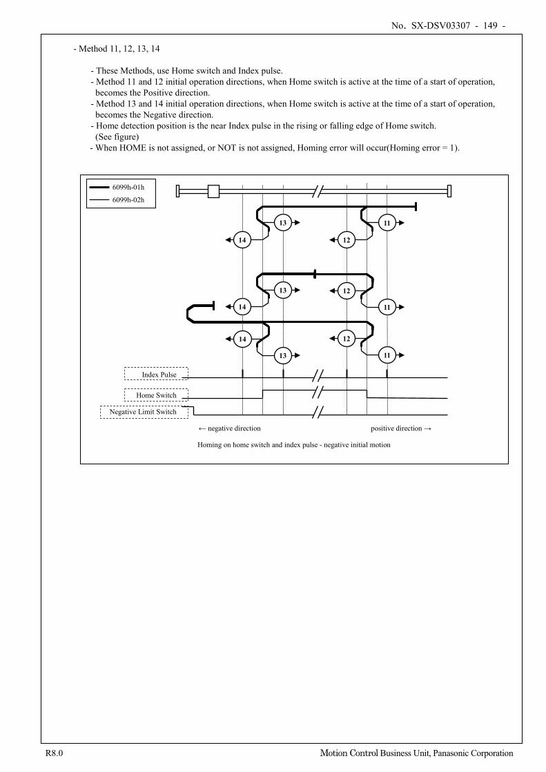
No. SX-DSV03307 - 149 -
R8.0 Motion Control Business Unit, Panasonic Corporation
- Method 11, 12, 13, 14
- These Methods, use Home switch and Index pulse. - Method 11 and 12 initial operation directions, when Home switch is active at the time of a start of operation, becomes the Positive direction. - Method 13 and 14 initial operation directions, when Home switch is active at the time of a start of operation, becomes the Negative direction. - Home detection position is the near Index pulse in the rising or falling edge of Home switch.
(See figure) - When HOME is not assigned, or NOT is not assigned, Homing error will occur(Homing error = 1).
Index Pulse
Home Switch
Negative Limit Switch
Homing on home switch and index pulse - negative initial motion
← negative direction positive direction →
11
11
11
6099h-01h
6099h-02h
12
12
12
13
13
13
14
14
14
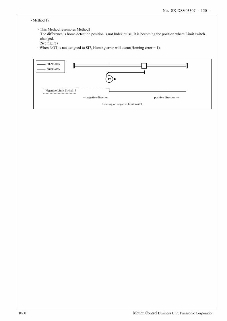
No. SX-DSV03307 - 150 -
R8.0 Motion Control Business Unit, Panasonic Corporation
- Method 17
- This Method resembles Method1.
The difference is home detection position is not Index pulse. It is becoming the position where Limit switch changed. (See figure)
- When NOT is not assigned to SI7, Homing error will occur(Homing error = 1).
Negative Limit Switch
Homing on negative limit switch
← negative direction positive direction →
17
6099h-01h
6099h-02h
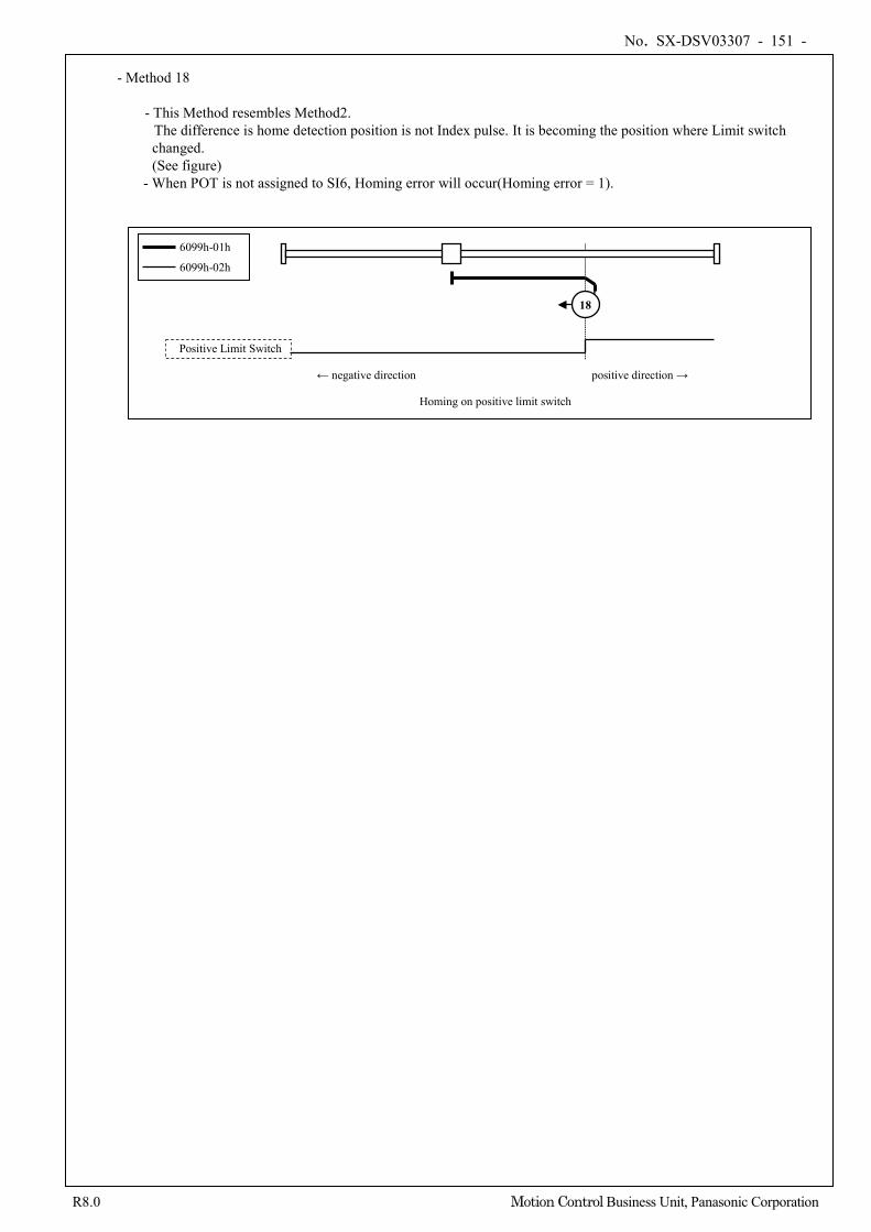
No. SX-DSV03307 - 151 -
R8.0 Motion Control Business Unit, Panasonic Corporation
- Method 18
- This Method resembles Method2.
The difference is home detection position is not Index pulse. It is becoming the position where Limit switch changed.
(See figure) - When POT is not assigned to SI6, Homing error will occur(Homing error = 1).
Positive Limit Switch
Homing on positive limit switch
← negative direction positive direction →
18
6099h-01h
6099h-02h
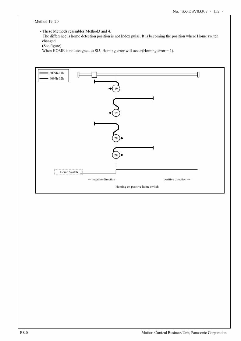
No. SX-DSV03307 - 152 -
R8.0 Motion Control Business Unit, Panasonic Corporation
- Method 19, 20
- These Methods resembles Method3 and 4.
The difference is home detection position is not Index pulse. It is becoming the position where Home switch changed.
(See figure) - When HOME is not assigned to SI5, Homing error will occur(Homing error = 1).
Home Switch
Homing on positive home switch
← negative direction positive direction →
19
19
6099h-01h
6099h-02h
20
20
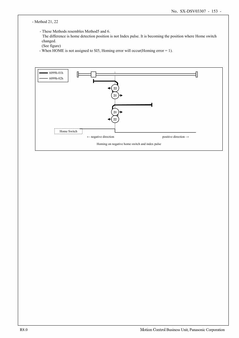
No. SX-DSV03307 - 153 -
R8.0 Motion Control Business Unit, Panasonic Corporation
- Method 21, 22
- These Methods resembles Method5 and 6.
The difference is home detection position is not Index pulse. It is becoming the position where Home switch changed.
(See figure) - When HOME is not assigned to SI5, Homing error will occur(Homing error = 1).
Home Switch
Homing on negative home switch and index pulse
← negative direction positive direction →
6099h-01h
6099h-02h
21
22
22
21
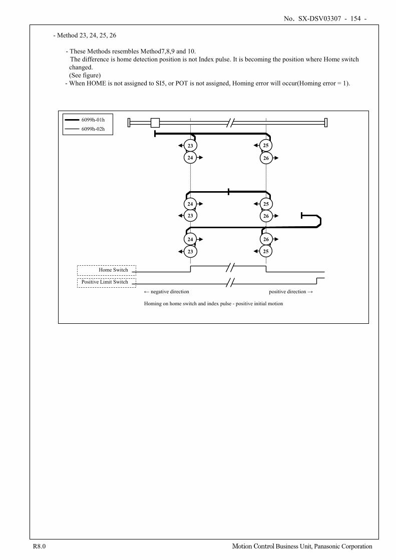
No. SX-DSV03307 - 154 -
R8.0 Motion Control Business Unit, Panasonic Corporation
- Method 23, 24, 25, 26
- These Methods resembles Method7,8,9 and 10.
The difference is home detection position is not Index pulse. It is becoming the position where Home switch changed.
(See figure) - When HOME is not assigned to SI5, or POT is not assigned, Homing error will occur(Homing error = 1).
Home Switch
Positive Limit Switch
Homing on home switch and index pulse - positive initial motion
← negative direction positive direction →
6099h-01h
6099h-02h
23
23
24
24
24
23
25
26
26
26
25
25
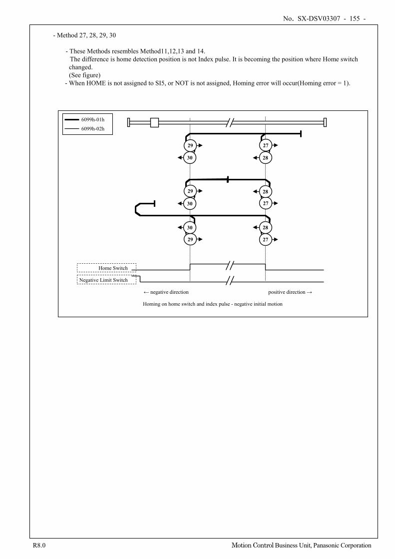
No. SX-DSV03307 - 155 -
R8.0 Motion Control Business Unit, Panasonic Corporation
- Method 27, 28, 29, 30
- These Methods resembles Method11,12,13 and 14.
The difference is home detection position is not Index pulse. It is becoming the position where Home switch changed.
(See figure) - When HOME is not assigned to SI5, or NOT is not assigned, Homing error will occur(Homing error = 1).
Home Switch
Negative Limit Switch
Homing on home switch and index pulse - negative initial motion
← negative direction positive direction →
6099h-01h
6099h-02h
27
27
28
28
28
27
29
30
30
30
29
29
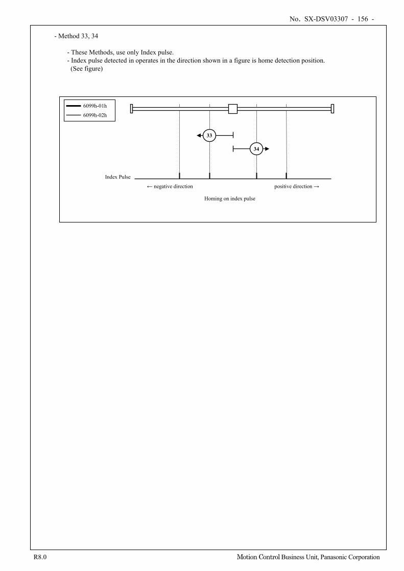
No. SX-DSV03307 - 156 -
R8.0 Motion Control Business Unit, Panasonic Corporation
- Method 33, 34
- These Methods, use only Index pulse. - Index pulse detected in operates in the direction shown in a figure is home detection position.
(See figure)
Index Pulse
Homing on index pulse
← negative direction positive direction →
33
6099h-01h
6099h-02h
34
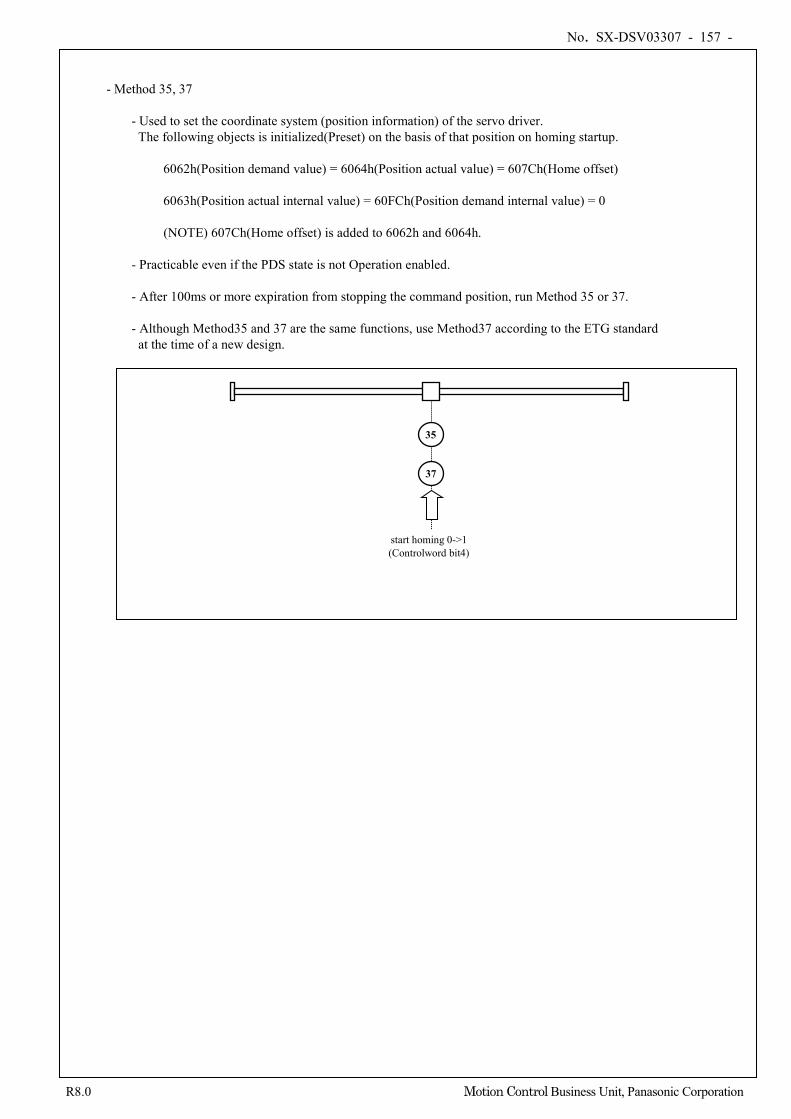
No. SX-DSV03307 - 157 -
R8.0 Motion Control Business Unit, Panasonic Corporation
- Method 35, 37
- Used to set the coordinate system (position information) of the servo driver. The following objects is initialized(Preset) on the basis of that position on homing startup.
6062h(Position demand value) = 6064h(Position actual value) = 607Ch(Home offset) 6063h(Position actual internal value) = 60FCh(Position demand internal value) = 0
(NOTE) 607Ch(Home offset) is added to 6062h and 6064h.
- Practicable even if the PDS state is not Operation enabled. - After 100ms or more expiration from stopping the command position, run Method 35 or 37. - Although Method35 and 37 are the same functions, use Method37 according to the ETG standard at the time of a new design.
start homing 0->1 (Controlword bit4)
37
35
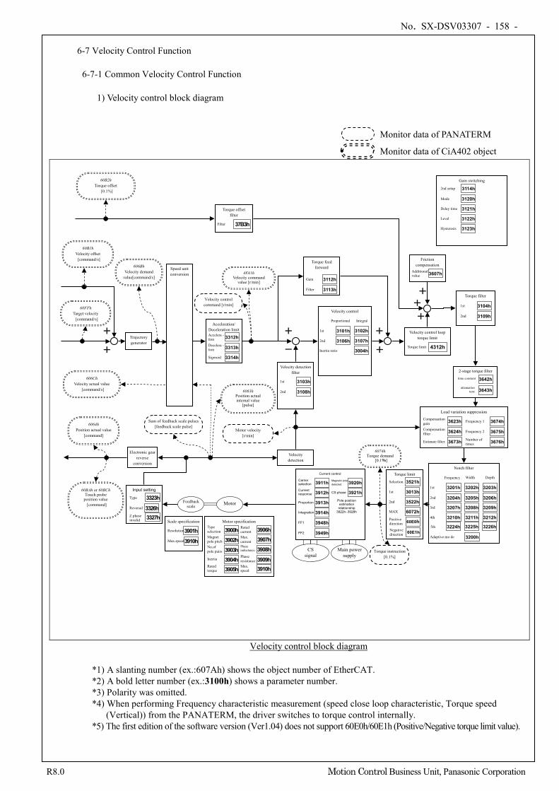
No. SX-DSV03307 - 158 -
R8.0 Motion Control Business Unit, Panasonic Corporation
6-7 Velocity Control Function
6-7-1 Common Velocity Control Function
1) Velocity control block diagram
Velocity detection
+
-
Friction compensation
Additional value 3607h
Gain switching
2nd setup 3114h
Mode 3120h Delay time 3121h
Level 3122h
Hysteresis 3123h
Torque feed forward
Gain 3112h
Filter 3113h
+ +
+
+
6063h Position actual internal value
[pulse]
Velocity detection filter
1st 3103h 2nd 3108h
Velocity control
3102h
3107h
Proportional Integral
Inertia ratio
1st 3101h
2nd 3106h 3004h
Acceleration/ Deceleration limit Accelera - tion 3312h Decelera - tion 3313h
Sigmoid 3314h
Speed unit conversion
60FFh Target velocity [command/s]
6064h Position actual value
[command]
60BAh or 60BCh Touch probe
position value [command]
606Ch Velocity actual value
[command/s]
60B2h Torque offset
[0.1%]
60B1h Velocity offset [command/s]
+
+
Electronic gear reverse
conversion
Velocity control command [r/min]
Motor velocity [r/min]
Sum of feedback scale pulses [feedback scale pulse]
Notch filter
3203h
3206h
3209h
3212h
Depth
3202h
3205h
3208h
3211h
Width
1st 3201h
2nd 3204h 3rd 3207h
4th 3210h
Frequency
Adaptive mo de 3200h
Torque filter
1st 3104h
2nd 3109h
2-stage torque filter
3642h
3643h
time constant
attenuation term
5th 3226h 3225h 3224h
Load variation suppression
Compensation gain 3623h Compensation filter 3624h
Estimate filter 3673h
Frequency 1 3674h
Frequency 2 3675h Number of times 3676h
4FA1h Velocity command
value [r/min]
Trajectory generator
606Bh Velocity demand
value[command/s]
Torque offset filter
Filter 37B3h
Velocity control loop torque limit
Torque limit
4312h
+
Input setting
3326h Reversal
Type 3323h
Z phase invalid 3327h
Scale specification
Resolution 3901h Max.speed 3910h
Motor specification
Magnet pole pitch No.of pole pairs
Type selection
Inertia
Rated torque
Rated current Max. current
Max. speed
Phase inductance
Phase resistance
3900h 3902h 3903h 3904h 3905h
3906h 3907h 3908h 3909h 3910h
6074h Torque demand
[0.1%]
Torque instruction [0.1%]
Torque limit
Selection 3521h
MAX 6072h
1st 3013h
2nd 3522h
Positive direction 60E0h Negative direction 60E1h
CS signal
Main power supply
Current control
Current response 3912h
Proportion 3913h
Carrier selection 3911h
Integration 3914h
Magnetic pole detected 3920h
CS phase 3921h
Pole position estimation relationship
3922h–3928h
FF1 3948h
FF2 3949h
Feedback scale Motor
Velocity control block diagram
*1) A slanting number (ex.:607Ah) shows the object number of EtherCAT. *2) A bold letter number (ex.:3100h) shows a parameter number. *3) Polarity was omitted. *4) When performing Frequency characteristic measurement (speed close loop characteristic, Torque speed
(Vertical)) from the PANATERM, the driver switches to torque control internally. *5) The first edition of the software version (Ver1.04) does not support 60E0h/60E1h (Positive/Negative torque limit value).
Monitor data of PANATERM
Monitor data of CiA402 object
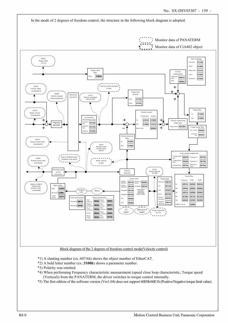
No. SX-DSV03307 - 159 -
R8.0 Motion Control Business Unit, Panasonic Corporation
In the mode of 2 degrees of freedom control, the structure in the following block diagram is adopted.
Velocity detection
+
-
Friction compensation
Additional value 3607h
Gain switching
2nd setup 3114h
Mode 3120h Delay time 3121h
Level 3122h
Hysteresis 3123h
Torque feed forward
Gain 3112h
Filter 3113h
+
+
6063h Position actual internal value
[pulse]
Velocity detection filter
1st 3103h 2nd 3108h
Velocity control
3102h
3107h
Proportional Integral
Inertia ratio
1st 3101h
2nd 3106h 3004h
Acceleration/ Deceleration limit Accelera - tion 3312h Decelera - tion 3313h
Sigmoid 3314h
Speed unit conversion
6064h Position actual value
[command]
60BAh or 60BCh Touch probe
position value [command]
606Ch Velocity actual value
[command/s]
60B2h Torque offset
[0.1%]
Electronic gear reverse
conversion
Velocity control command [r/min]
Motor velocity [r/min]
Sum of feedback pulses [feedback scale pulse]
Notch filter
3203h
3206h
3209h
3212h
Depth
3202h
3205h
3208h
3211h
Width
1st 3201h
2nd 3204h 3rd 3207h
4th 3210h
Frequency
Adaptive mo de 3200h
Torque filter
1st 3104h
2nd 3109h
2-stage torque filter
3642h
3643h
time constant
attenuation term
5th 3226h 3225h 3224h
Load variation suppression
Compensation gain 3623h Compensation filter 3624h
Estimate filter 3673h
Frequency 1 3674h
Frequency 2 3675h Number of times 3676h
60B1h Velocity offset [command/s]
+
+ Trajectory generator
606Bh Velocity demand
value[command/s]
4FA1h Velocity command
value [r/min]
60FFh Target velocity [command/s]
Torque offset filter
Filter 37B3h
+ +
Velocity control loop torque limit
Torque limit 4312h
+
Gain 3650h
Input setting
3326h Reversal
Type 3323h
Z phase invalid 3327h
6074h Torque demand
[0.1%]
Torque instruction [0.1%]
Torque limit
Selection 3521h
MAX 6072h
1st 3013h
2nd 3522h
Positive direction 60E0h Negative direction 60E1h
CS signal
Main power supply
Current control
Current response 3912h
Proportion 3913h
Carrier selection 3911h
Integration 3914h
Magnetic pole detected 3920h
CS phase 3921h
Pole position estimation relationship
3922h–3928h
FF1 3948h
FF2 3949h
Feedback scale Motor
Scale specification
Resolution 3901h Max.speed 3910h
Motor specification
Magnet pole pitch No.of pole pairs
Type selection
Inertia
Rated torque
Rated current Max. current
Max. speed
Phase inductance
Phase resistance
3900h 3902h 3903h 3904h 3905h
3906h 3907h 3908h 3909h 3910h
Block diagram of the 2 degrees of freedom control mode(Velocity control)
*1) A slanting number (ex.:607Ah) shows the object number of EtherCAT. *2) A bold letter number (ex.:3100h) shows a parameter number. *3) Polarity was omitted. *4) When performing Frequency characteristic measurement (speed close loop characteristic, Torque speed
(Vertical)) from the PANATERM, the driver switches to torque control internally. *5) The first edition of the software version (Ver1.04) does not support 60E0h/60E1h (Positive/Negative torque limit value).
Monitor data of PANATERM
Monitor data of CiA402 object
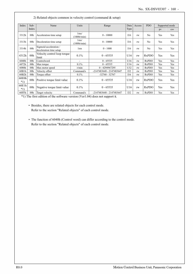
No. SX-DSV03307 - 160 -
R8.0 Motion Control Business Unit, Panasonic Corporation
2) Related objects common in velocity control (command & setup)
Index Sub-
Index Name Units Range Data
Type Access PDO Supported mode
pv csv
3312h 00h Acceleration time setup 1ms/ (1000r/min) 0 - 10000 I16 rw No Yes Yes
3313h 00h Deceleration time setup 1ms/ (1000r/min) 0 - 10000 I16 rw No Yes Yes
3314h 00h Sigmoid acceleration / deceleration time setup 1ms 0 - 1000 I16 rw No Yes Yes
4312h 00h Velocity control loop torque limit 0.1% 0 - 65535 U16 rw RxPDO Yes Yes
6040h 00h Controlword - 0 - 65535 U16 rw RxPDO Yes Yes 6072h 00h Max torque 0.1% 0 - 65535 U16 rw RxPDO Yes Yes 6080h 00h Max motor speed r/min 0 - 4294967295 U32 rw RxPDO Yes Yes 60B1h 00h Velocity offset Command/s -2147483648 - 2147483647 I32 rw RxPDO Yes Yes 60B2h 00h Torque offset 0.1% -32768 - 32767 I16 rw RxPDO Yes Yes 60E0h
*1) 00h Positive torque limit value 0.1% 0 - 65535 U16 rw RxPDO Yes Yes
60E1h *1) 00h Negative torque limit value 0.1% 0 - 65535 U16 rw RxPDO Yes Yes
60FFh 00h Target velocity Command/s -2147483648 - 2147483647 I32 rw RxPDO Yes Yes *1) The first edition of the software version (Ver1.04) does not support it.
• Besides, there are related objects for each control mode.
Refer to the section "Related objects" of each control mode. • The function of 6040h (Control word) can differ according to the control mode.
Refer to the section "Related objects" of each control mode.
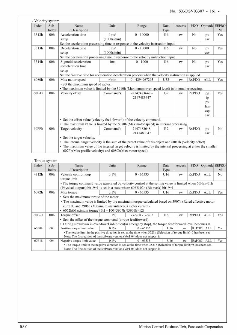
No. SX-DSV03307 - 161 -
R8.0 Motion Control Business Unit, Panasonic Corporation
- Velocity system Index Sub-
Index Name
/ Description Units Range Data
Type Access PDO Opmode EEPRO
M 3312h 00h Acceleration time
setup 1ms/
(1000r/min) 0 - 10000 I16 rw No pv
csv Yes
Set the acceleration processing time in response to the velocity instruction input. 3313h 00h Deceleration time
setup 1ms/
(1000r/min) 0 - 10000 I16 rw No pv
csv Yes
Set the deceleration processing time in response to the velocity instruction input. 3314h 00h Sigmoid acceleration
/deceleration time setup
1ms 0 - 1000 I16 rw No pv csv
Yes
Set the S-curve time for acceleration/deceleration process when the velocity instruction is applied. 6080h 00h Max motor speed r/min 0 - 4294967295 U32 rw RxPDO ALL Yes
• Set the maximum speed of motor. • The maximum value is limited by the 3910h (Maximnum over speed level) in internal processing.
60B1h 00h Velocity offset Command/s -2147483648 - 2147483647
I32 rw RxPDO pp ip pv hm csp csv
Yes
• Set the offset value (velocity feed foward) of the velocity command. • The maximum value is limited by the 6080h (Max motor speed) in internal processing.
60FFh 00h Target velocity Command/s -2147483648 - 2147483647
I32 rw RxPDO pv csv
No
• Set the target velocity. • The internal target velocity is the sum of the preset value of this object and 60B1h (Velocity offset). • The maximum value of the internal target velocity is limited by the internal processing at either the smaller
607Fh(Max profile velocity) and 6080h(Max motor speed).
- Torque system Index Sub-
Index Name
/ Description Units Range Data
Type Access PDO Opmode EEPRO
M 4312h 00h Velocity control loop
torque limit 0.1% 0 - 65535 U16 rw RxPDO ALL No
• The torque command value generated by velocity control at the setting value is limited when 60FEh-01h (Physical outputs) bit19=1 is set in a state where 60FE-02h (Bit mask) bit19=1.
6072h 00h Max torque 0.1% 0 - 65535 U16 rw RxPDO ALL Yes • Sets the maximum torque of the motor. ・The maximum value is limited by the maximum torque calculated based on 3907h (Rated effective motor
current) and 3906h (Maximum instantaneous motor current). • 6072h(Maximum torque)[%] = 100×3907h /(3906h×√2)
60B2h 00h Torque offset 0.1% -32768 - 32767 I16 rw RxPDO ALL Yes • Sets the offset of the torque command (torque feedforward). • During slowdown in over-travel inhibition(in emergncy stop), the torque feedforward level becomes 0.
60E0h 00h Positive torque limit value 0.1% 0 – 65535 U16 rw RxPDO ALL Yes • The torque limit in the positive direction is set, at the time when 3521h (Selection of torque limit)=5 has been set. Note: The first edition of the software version (Ver1.04) does not support it.
60E1h 00h Negative torque limit value 0.1% 0 – 65535 U16 rw RxPDO ALL Yes • The torque limit in the negative direction is set, at the time when 3521h (Selection of torque limit)=5 has been set. Note: The first edition of the software version (Ver1.04) does not support it.
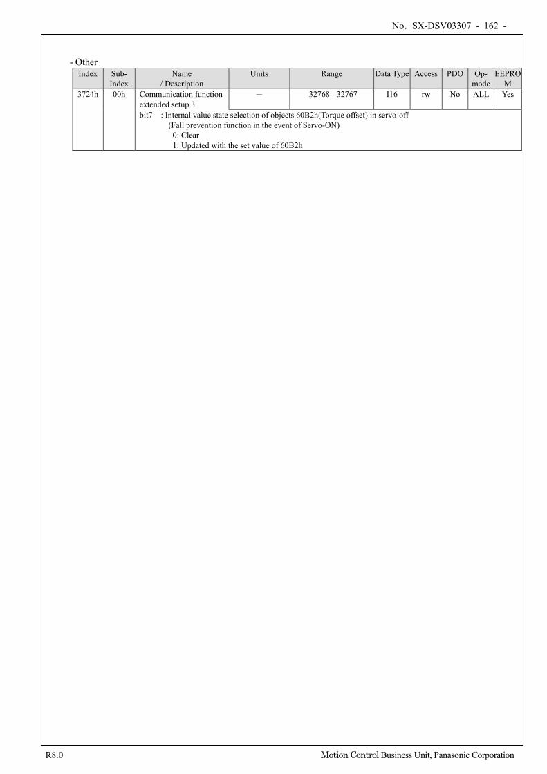
No. SX-DSV03307 - 162 -
R8.0 Motion Control Business Unit, Panasonic Corporation
- Other Index Sub-
Index Name
/ Description Units Range Data Type Access PDO Op-
mode EEPRO
M 3724h 00h Communication function
extended setup 3 - -32768 - 32767 I16 rw No ALL Yes
bit7 : Internal value state selection of objects 60B2h(Torque offset) in servo-off (Fall prevention function in the event of Servo-ON)
0: Clear 1: Updated with the set value of 60B2h
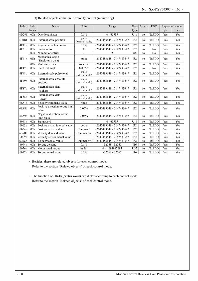
No. SX-DSV03307 - 163 -
R8.0 Motion Control Business Unit, Panasonic Corporation
3) Related objects common in velocity control (monitoring)
Index Sub-
Index Name Units Range Data
Type Access PDO Supported mode
pv csv 4D29h 00h Over load factor 0.1% 0 - 65535 U16 ro TxPDO Yes Yes
4F0Dh 00h External scale position pulse (external scale) -2147483648 - 2147483647 I32 ro TxPDO Yes Yes
4F11h 00h Regenerative load ratio 0.1% -2147483648 - 2147483647 I32 ro TxPDO Yes Yes 4F31h 00h Inertia ratio % -2147483648 - 2147483647 I32 ro No Yes Yes
4F41h
00h Number of entries - 2 U8 ro No Yes Yes
01h Mechanical angle (Single-turn data) pulse -2147483648 - 2147483647 I32 ro TxPDO Yes Yes
02h Multi-turn data rotation -2147483648 - 2147483647 I32 ro TxPDO Yes Yes 4F42h 00h Electrical angle 0.0879° -2147483648 - 2147483647 I32 ro No Yes Yes
4F48h 00h External scale pulse total pulse (external scale) -2147483648 - 2147483647 I32 ro TxPDO Yes Yes
4F49h 00h External scale absolute position
pulse (external scale) -2147483648 - 2147483647 I32 ro TxPDO Yes Yes
4F87h 00h External scale data (Higher)
pulse (external scale) -2147483648 - 2147483647 I32 ro TxPDO Yes Yes
4F88h 00h External scale data (Lower)
pulse (external scale) -2147483648 - 2147483647 I32 ro TxPDO Yes Yes
4FA1h 00h Velocity command value r/min -2147483648 - 2147483647 I32 ro TxPDO Yes Yes
4FA8h 00h Positive direction torque limit value 0.05% -2147483648 - 2147483647 I32 ro TxPDO Yes Yes
4FA9h 00h Negative direction torque limit value 0.05% -2147483648 - 2147483647 I32 ro TxPDO Yes Yes
6041h 00h Statusword - 0 - 65535 U16 ro TxPDO Yes Yes 6063h 00h Position actual internal value pulse -2147483648 - 2147483647 I32 ro TxPDO Yes Yes 6064h 00h Position actual value Command -2147483648 - 2147483647 I32 ro TxPDO Yes Yes 606Bh 00h Velocity demand value Command/s -2147483648 - 2147483647 I32 ro TxPDO Yes Yes 6069h 00h Velocity sensor actual value - -2147483648 - 2147483647 I32 ro TxPDO Yes Yes 606Ch 00h Velocity actual value Command/s -2147483648 - 2147483647 I32 ro TxPDO Yes Yes 6074h 00h Torque demand 0.1% -32768 - 32767 I16 ro TxPDO Yes Yes 6076h 00h Motor rated torque mNm 0 – 4294967295 U32 ro TxPDO Yes Yes 6077h 00h Torque actual value 0.1% -32768 - 32767 I16 ro TxPDO Yes Yes
• Besides, there are related objects for each control mode.
Refer to the section "Related objects" of each control mode. • The function of 6041h (Status word) can differ according to each control mode.
Refer to the section "Related objects" of each control mode.
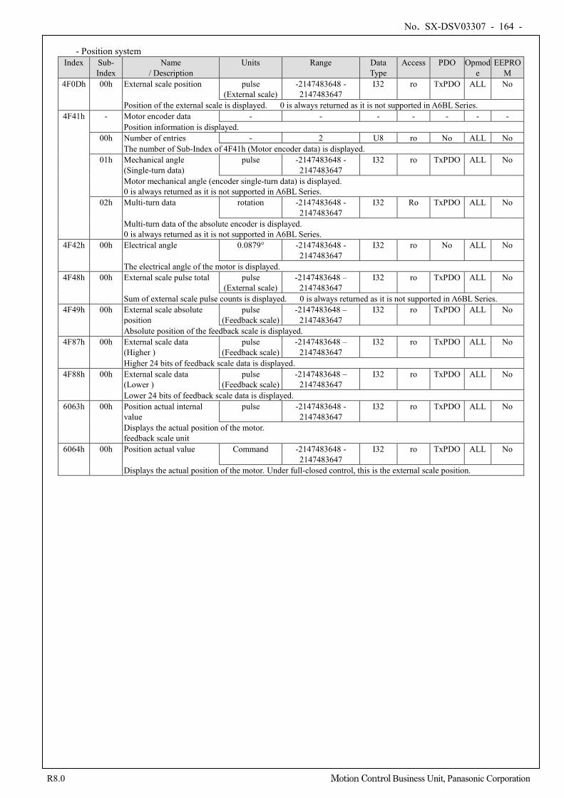
No. SX-DSV03307 - 164 -
R8.0 Motion Control Business Unit, Panasonic Corporation
- Position system
Index Sub- Index
Name / Description
Units Range Data Type
Access PDO Opmode
EEPROM
4F0Dh 00h External scale position pulse (External scale)
-2147483648 - 2147483647
I32 ro TxPDO ALL No
Position of the external scale is displayed. 0 is always returned as it is not supported in A6BL Series. 4F41h - Motor encoder data - - - - - - -
Position information is displayed. 00h Number of entries - 2 U8 ro No ALL No
The number of Sub-Index of 4F41h (Motor encoder data) is displayed. 01h Mechanical angle
(Single-turn data) pulse -2147483648 -
2147483647 I32 ro TxPDO ALL No
Motor mechanical angle (encoder single-turn data) is displayed. 0 is always returned as it is not supported in A6BL Series.
02h Multi-turn data rotation -2147483648 - 2147483647
I32 Ro TxPDO ALL No
Multi-turn data of the absolute encoder is displayed. 0 is always returned as it is not supported in A6BL Series.
4F42h 00h Electrical angle 0.0879° -2147483648 - 2147483647
I32 ro No ALL No
The electrical angle of the motor is displayed. 4F48h 00h External scale pulse total pulse
(External scale) -2147483648 –
2147483647 I32 ro TxPDO ALL No
Sum of external scale pulse counts is displayed. 0 is always returned as it is not supported in A6BL Series. 4F49h 00h External scale absolute
position pulse
(Feedback scale) -2147483648 –
2147483647 I32 ro TxPDO ALL No
Absolute position of the feedback scale is displayed. 4F87h 00h External scale data
(Higher ) pulse
(Feedback scale) -2147483648 –
2147483647 I32 ro TxPDO ALL No
Higher 24 bits of feedback scale data is displayed. 4F88h 00h External scale data
(Lower ) pulse
(Feedback scale) -2147483648 –
2147483647 I32 ro TxPDO ALL No
Lower 24 bits of feedback scale data is displayed. 6063h 00h Position actual internal
value pulse -2147483648 -
2147483647 I32 ro TxPDO ALL No
Displays the actual position of the motor. feedback scale unit
6064h 00h Position actual value Command -2147483648 - 2147483647
I32 ro TxPDO ALL No
Displays the actual position of the motor. Under full-closed control, this is the external scale position.
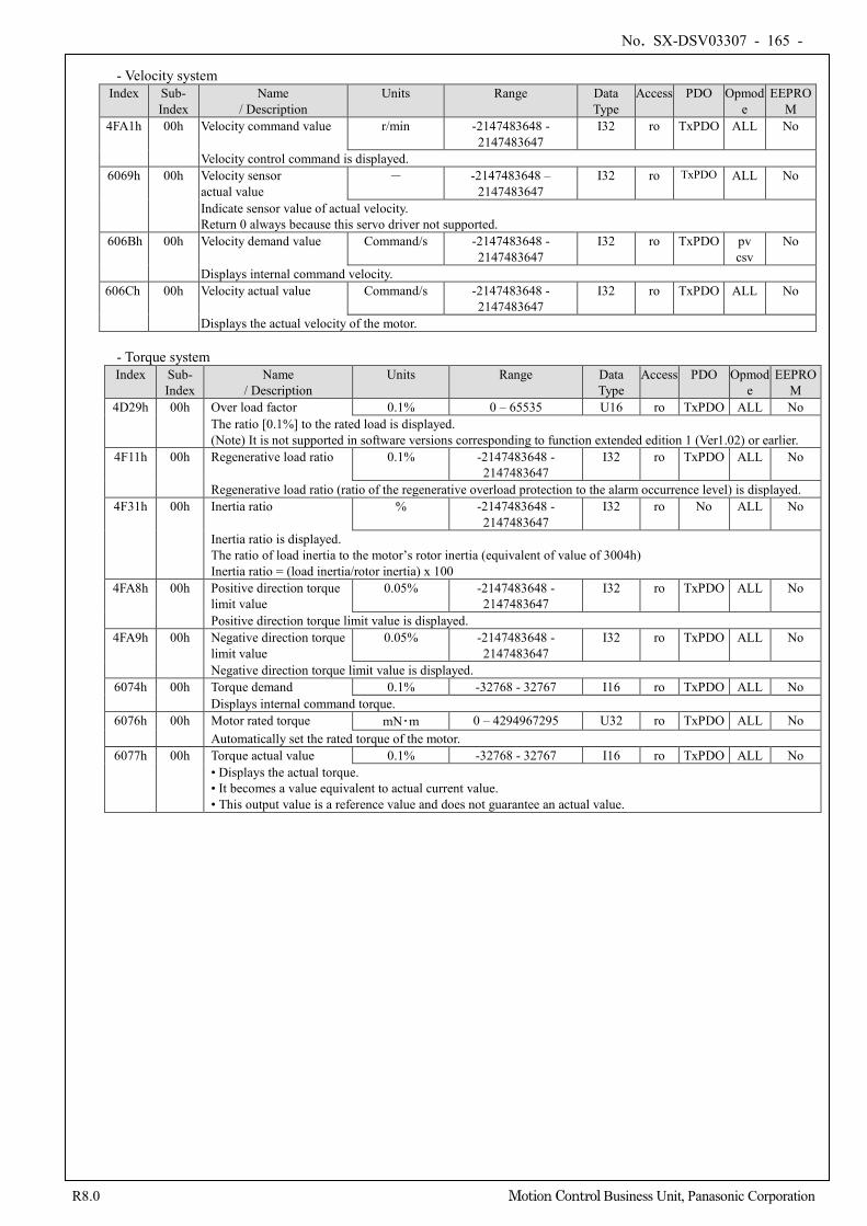
No. SX-DSV03307 - 165 -
R8.0 Motion Control Business Unit, Panasonic Corporation
- Velocity system Index Sub-
Index Name
/ Description Units Range Data
Type Access PDO Opmod
e EEPRO
M 4FA1h 00h Velocity command value r/min -2147483648 -
2147483647 I32 ro TxPDO ALL No
Velocity control command is displayed. 6069h 00h Velocity sensor
actual value - -2147483648 –
2147483647 I32 ro TxPDO ALL No
Indicate sensor value of actual velocity. Return 0 always because this servo driver not supported.
606Bh 00h Velocity demand value Command/s -2147483648 - 2147483647
I32 ro TxPDO pv csv
No
Displays internal command velocity. 606Ch 00h Velocity actual value Command/s -2147483648 -
2147483647 I32 ro TxPDO ALL No
Displays the actual velocity of the motor.
- Torque system Index Sub-
Index Name
/ Description Units Range Data
Type Access PDO Opmod
e EEPRO
M 4D29h 00h Over load factor 0.1% 0 – 65535 U16 ro TxPDO ALL No
The ratio [0.1%] to the rated load is displayed. (Note) It is not supported in software versions corresponding to function extended edition 1 (Ver1.02) or earlier.
4F11h 00h Regenerative load ratio 0.1% -2147483648 - 2147483647
I32 ro TxPDO ALL No
Regenerative load ratio (ratio of the regenerative overload protection to the alarm occurrence level) is displayed. 4F31h 00h Inertia ratio % -2147483648 -
2147483647 I32 ro No ALL No
Inertia ratio is displayed. The ratio of load inertia to the motor’s rotor inertia (equivalent of value of 3004h) Inertia ratio = (load inertia/rotor inertia) x 100
4FA8h 00h Positive direction torque limit value
0.05% -2147483648 - 2147483647
I32 ro TxPDO ALL No
Positive direction torque limit value is displayed. 4FA9h 00h Negative direction torque
limit value 0.05% -2147483648 -
2147483647 I32 ro TxPDO ALL No
Negative direction torque limit value is displayed. 6074h 00h Torque demand 0.1% -32768 - 32767 I16 ro TxPDO ALL No
Displays internal command torque. 6076h 00h Motor rated torque mN・m 0 – 4294967295 U32 ro TxPDO ALL No
Automatically set the rated torque of the motor. 6077h 00h Torque actual value 0.1% -32768 - 32767 I16 ro TxPDO ALL No
• Displays the actual torque. • It becomes a value equivalent to actual current value. • This output value is a reference value and does not guarantee an actual value.
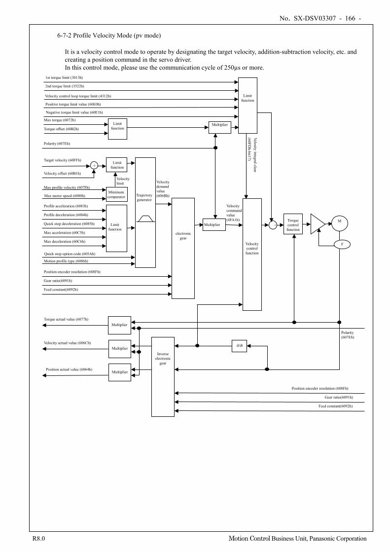
No. SX-DSV03307 - 166 -
R8.0 Motion Control Business Unit, Panasonic Corporation
6-7-2 Profile Velocity Mode (pv mode)
It is a velocity control mode to operate by designating the target velocity, addition-subtraction velocity, etc. and creating a position command in the servo driver. In this control mode, please use the communication cycle of 250µs or more.
Velocity control function
+ Torque control
function
M
F
Minimum comparator
Limit function
Polarity (607Eh)
Target velocity (60FFh)
Max motor speed (6080h)
Max profile velocity (607Fh)
Limit function
Profile acceleration (6083h)
Profile deceleration (6084h)
Quick stop deceleration (6085h)
Max acceleration (60C5h)
Max deceleration (60C6h)
Trajectory generator
Velocity limit
d/dt
Multiplier
Motion profile type (6086h)
Velocity demand value (606Bh)
+
Velocity offset (60B1h)
Limit function
Multiplier Max torque (6072h)
Torque offset (60B2h)
Torque actual value (6077h)
Velocity actual value (606Ch)
Multiplier Position actual value (6064h)
Multiplier
Multiplier
Polarity (607Eh)
Inverse electronic
gear
Feed constant(6092h)
Gear ratio(6091h)
Position encoder resolution (608Fh)
electronic gear
Feed constant(6092h)
Gear ratio(6091h)
Position encoder resolution (608Fh)
Limit function
Quick stop option code (605Ah)
Velocity command value (4FA1h)
1st torque limit (3013h)
Positive torque limit value (60E0h) Negative torque limit value (60E1h)
2nd torque limit (3522h) Velocity control loop torque limit (4312h)
Velosity integral clear (60FD
h-bit17)
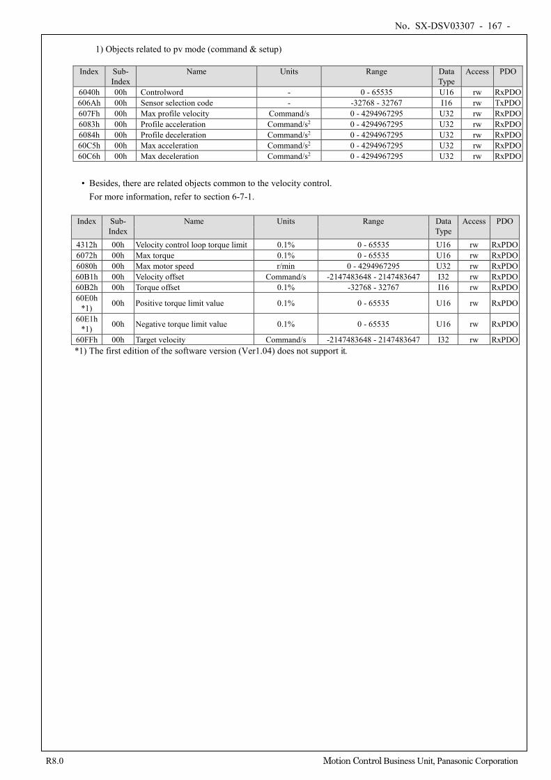
No. SX-DSV03307 - 167 -
R8.0 Motion Control Business Unit, Panasonic Corporation
1) Objects related to pv mode (command & setup)
Index Sub-
Index Name Units Range Data
Type Access PDO
6040h 00h Controlword - 0 - 65535 U16 rw RxPDO 606Ah 00h Sensor selection code - -32768 - 32767 I16 rw TxPDO 607Fh 00h Max profile velocity Command/s 0 - 4294967295 U32 rw RxPDO 6083h 00h Profile acceleration Command/s2 0 - 4294967295 U32 rw RxPDO 6084h 00h Profile deceleration Command/s2 0 - 4294967295 U32 rw RxPDO 60C5h 00h Max acceleration Command/s2 0 - 4294967295 U32 rw RxPDO 60C6h 00h Max deceleration Command/s2 0 - 4294967295 U32 rw RxPDO • Besides, there are related objects common to the velocity control.
For more information, refer to section 6-7-1.
Index Sub- Index
Name Units Range Data Type
Access PDO
4312h 00h Velocity control loop torque limit 0.1% 0 - 65535 U16 rw RxPDO 6072h 00h Max torque 0.1% 0 - 65535 U16 rw RxPDO 6080h 00h Max motor speed r/min 0 - 4294967295 U32 rw RxPDO 60B1h 00h Velocity offset Command/s -2147483648 - 2147483647 I32 rw RxPDO 60B2h 00h Torque offset 0.1% -32768 - 32767 I16 rw RxPDO 60E0h
*1) 00h Positive torque limit value 0.1% 0 - 65535 U16 rw RxPDO
60E1h *1) 00h Negative torque limit value 0.1% 0 - 65535 U16 rw RxPDO
60FFh 00h Target velocity Command/s -2147483648 - 2147483647 I32 rw RxPDO *1) The first edition of the software version (Ver1.04) does not support it.
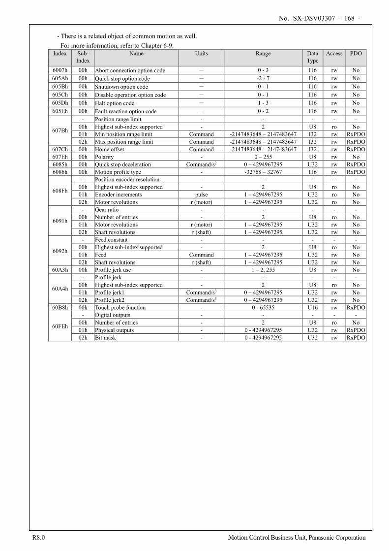
No. SX-DSV03307 - 168 -
R8.0 Motion Control Business Unit, Panasonic Corporation
- There is a related object of common motion as well. For more information, refer to Chapter 6-9.
Index Sub- Index
Name Units Range Data Type
Access PDO
6007h 00h Abort connection option code - 0 - 3 I16 rw No 605Ah 00h Quick stop option code - -2 - 7 I16 rw No 605Bh 00h Shutdown option code - 0 - 1 I16 rw No 605Ch 00h Disable operation option code - 0 - 1 I16 rw No 605Dh 00h Halt option code - 1 - 3 I16 rw No 605Eh 00h Fault reaction option code - 0 - 2 I16 rw No
607Bh
- Position range limit - - - - - 00h Highest sub-index supported - 2 U8 ro No 01h Min position range limit Command -2147483648 – 2147483647 I32 rw RxPDO 02h Max position range limit Command -2147483648 – 2147483647 I32 rw RxPDO
607Ch 00h Home offset Command -2147483648 – 2147483647 I32 rw RxPDO 607Eh 00h Polarity - 0 – 255 U8 rw No 6085h 00h Quick stop deceleration Command/s2 0 – 4294967295 U32 rw RxPDO 6086h 00h Motion profile type - -32768 – 32767 I16 rw RxPDO
608Fh
- Position encoder resolution - - - - - 00h Highest sub-index supported - 2 U8 ro No 01h Encoder increments pulse 1 – 4294967295 U32 ro No 02h Motor revolutions r (motor) 1 – 4294967295 U32 ro No
6091h
- Gear ratio - - - - - 00h Number of entries - 2 U8 ro No 01h Motor revolutions r (motor) 1 – 4294967295 U32 rw No 02h Shaft revolutions r (shaft) 1 – 4294967295 U32 rw No
6092h
- Feed constant - - - - - 00h Highest sub-index supported - 2 U8 ro No 01h Feed Command 1 – 4294967295 U32 rw No 02h Shaft revolutions r (shaft) 1 – 4294967295 U32 rw No
60A3h 00h Profile jerk use - 1 – 2, 255 U8 rw No
60A4h
- Profile jerk - - - - - 00h Highest sub-index supported - 2 U8 ro No 01h Profile jerk1 Command/s3 0 – 4294967295 U32 rw No 02h Profile jerk2 Command/s3 0 – 4294967295 U32 rw No
60B8h 00h Touch probe function - 0 - 65535 U16 rw RxPDO
60FEh
- Digital outputs - - - - - 00h Number of entries - 2 U8 ro No 01h Physical outputs - 0 - 4294967295 U32 rw RxPDO 02h Bit mask - 0 - 4294967295 U32 rw RxPDO
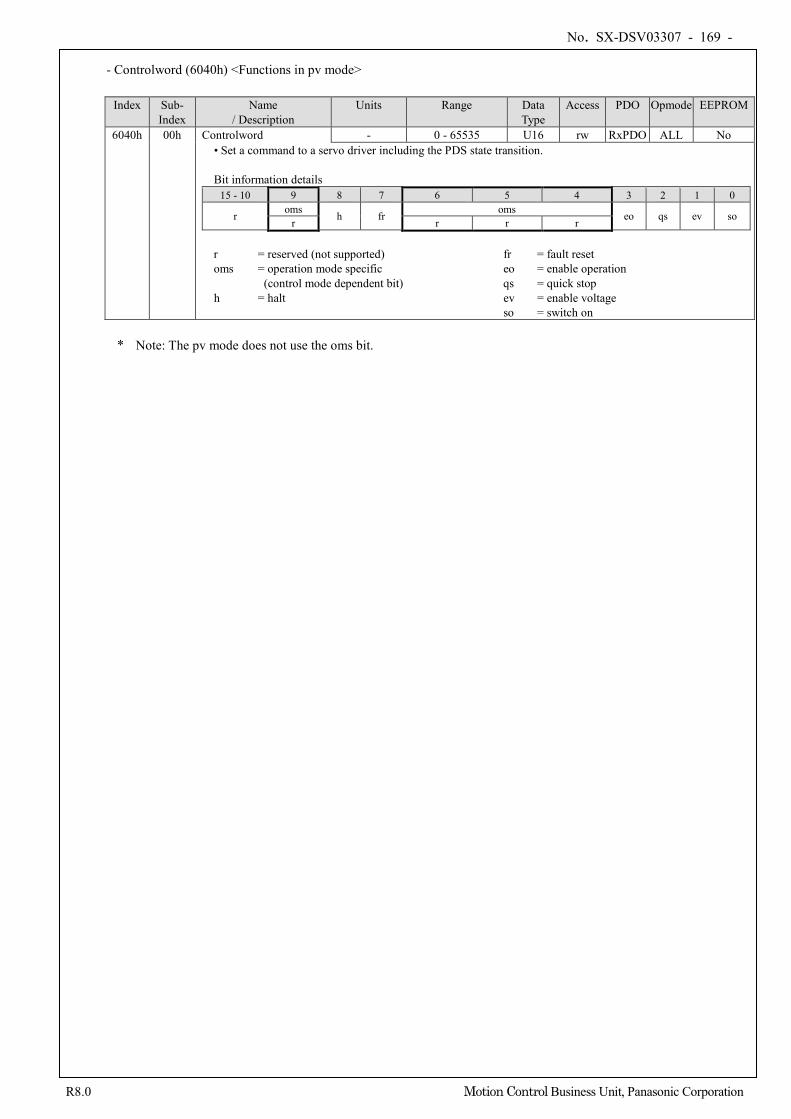
No. SX-DSV03307 - 169 -
R8.0 Motion Control Business Unit, Panasonic Corporation
- Controlword (6040h) <Functions in pv mode> Index Sub-
Index Name
/ Description Units Range Data
Type Access PDO Opmode EEPROM
6040h 00h Controlword - 0 - 65535 U16 rw RxPDO ALL No • Set a command to a servo driver including the PDS state transition. Bit information details
15 - 10 9 8 7 6 5 4 3 2 1 0
r oms h fr oms eo qs ev so r r r r r = reserved (not supported) fr = fault reset oms = operation mode specific eo = enable operation
(control mode dependent bit) qs = quick stop h = halt ev = enable voltage
so = switch on * Note: The pv mode does not use the oms bit.
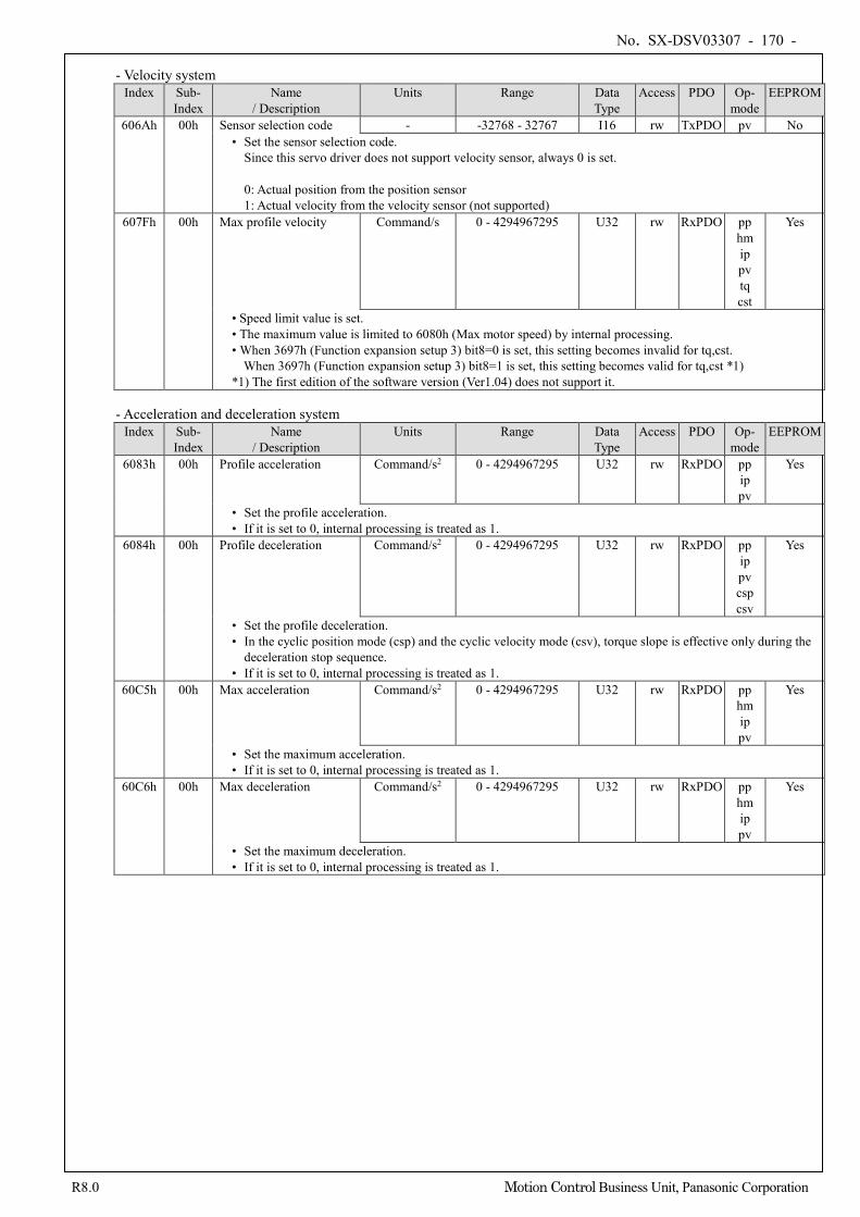
No. SX-DSV03307 - 170 -
R8.0 Motion Control Business Unit, Panasonic Corporation
- Velocity system Index Sub-
Index Name
/ Description Units Range Data
Type Access PDO Op-
mode EEPROM
606Ah 00h Sensor selection code - -32768 - 32767 I16 rw TxPDO pv No • Set the sensor selection code.
Since this servo driver does not support velocity sensor, always 0 is set. 0: Actual position from the position sensor 1: Actual velocity from the velocity sensor (not supported)
607Fh 00h Max profile velocity Command/s 0 - 4294967295 U32 rw RxPDO pp hm ip pv tq cst
Yes
• Speed limit value is set. • The maximum value is limited to 6080h (Max motor speed) by internal processing. • When 3697h (Function expansion setup 3) bit8=0 is set, this setting becomes invalid for tq,cst.
When 3697h (Function expansion setup 3) bit8=1 is set, this setting becomes valid for tq,cst *1) *1) The first edition of the software version (Ver1.04) does not support it.
- Acceleration and deceleration system
Index Sub- Index
Name / Description
Units Range Data Type
Access PDO Op- mode
EEPROM
6083h 00h Profile acceleration Command/s2 0 - 4294967295 U32 rw RxPDO pp ip pv
Yes
• Set the profile acceleration. • If it is set to 0, internal processing is treated as 1.
6084h 00h Profile deceleration Command/s2 0 - 4294967295 U32 rw RxPDO pp ip pv csp csv
Yes
• Set the profile deceleration. • In the cyclic position mode (csp) and the cyclic velocity mode (csv), torque slope is effective only during the
deceleration stop sequence. • If it is set to 0, internal processing is treated as 1.
60C5h 00h Max acceleration Command/s2 0 - 4294967295 U32 rw RxPDO pp hm ip pv
Yes
• Set the maximum acceleration. • If it is set to 0, internal processing is treated as 1.
60C6h 00h Max deceleration Command/s2 0 - 4294967295 U32 rw RxPDO pp hm ip pv
Yes
• Set the maximum deceleration. • If it is set to 0, internal processing is treated as 1.
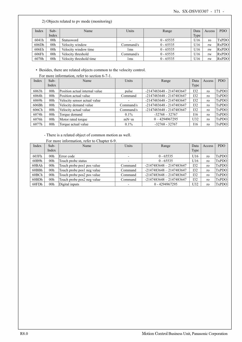
No. SX-DSV03307 - 171 -
R8.0 Motion Control Business Unit, Panasonic Corporation
2) Objects related to pv mode (monitoring) Index Sub-
Index Name Units Range Data
Type Access PDO
6041h 00h Statusword - 0 - 65535 U16 ro TxPDO 606Dh 00h Velocity window Command/s 0 - 65535 U16 rw RxPDO 606Eh 00h Velocity window time 1ms 0 - 65535 U16 rw RxPDO 606Fh 00h Velocity threshold Command/s 0 - 65535 U16 rw RxPDO 6070h 00h Velocity threshold time 1ms 0 - 65535 U16 rw RxPDO
• Besides, there are related objects common to the velocity control.
For more information, refer to section 6-7-1. Index Sub-
Index Name Units Range Data
Type Access PDO
6063h 00h Position actual internal value pulse -2147483648 - 2147483647 I32 ro TxPDO 6064h 00h Position actual value Command -2147483648 - 2147483647 I32 ro TxPDO 6069h 00h Velocity sensor actual value - -2147483648 - 2147483647 I32 ro TxPDO 606Bh 00h Velocity demand value Command/s -2147483648 - 2147483647 I32 ro TxPDO 606Ch 00h Velocity actual value Command/s -2147483648 - 2147483647 I32 ro TxPDO 6074h 00h Torque demand 0.1% -32768 – 32767 I16 ro TxPDO 6076h 00h Motor rated torque mN・m 0 – 4294967295 U32 ro TxPDO 6077h 00h Torque actual value 0.1% -32768 - 32767 I16 ro TxPDO
- There is a related object of common motion as well.
For more information, refer to Chapter 6-9. Index Sub-
Index Name Units Range Data
Type Access PDO
603Fh 00h Error code - 0 - 65535 U16 ro TxPDO 60B9h 00h Touch probe status - 0 - 65535 U16 ro TxPDO 60BAh 00h Touch probe pos1 pos value Command -2147483648 – 2147483647 I32 ro TxPDO 60BBh 00h Touch probe pos1 neg value Command -2147483648 – 2147483647 I32 ro TxPDO 60BCh 00h Touch probe pos2 pos value Command -2147483648 – 2147483647 I32 ro TxPDO 60BDh 00h Touch probe pos2 neg value Command -2147483648 – 2147483647 I32 ro TxPDO 60FDh 00h Digital inputs - 0 - 4294967295 U32 ro TxPDO
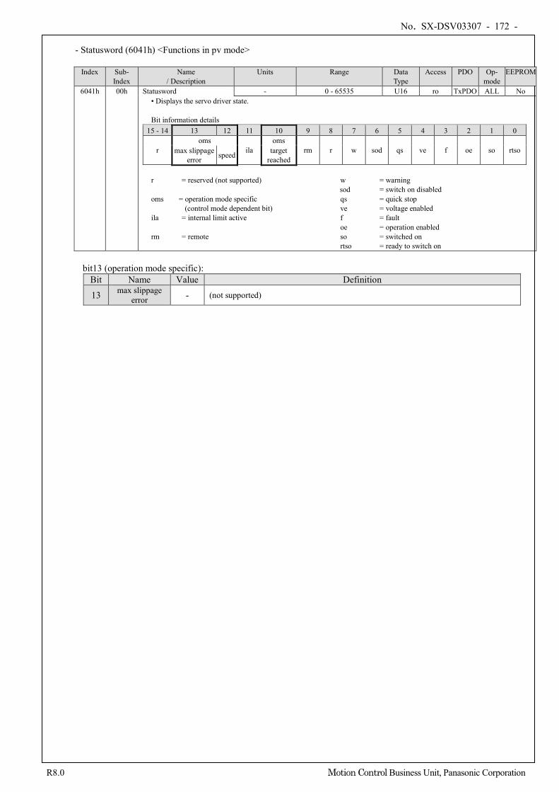
No. SX-DSV03307 - 172 -
R8.0 Motion Control Business Unit, Panasonic Corporation
- Statusword (6041h) <Functions in pv mode>
Index Sub-
Index Name
/ Description Units Range Data
Type Access PDO Op-
mode EEPROM
6041h 00h Statusword - 0 - 65535 U16 ro TxPDO ALL No • Displays the servo driver state. Bit information details
15 - 14 13 12 11 10 9 8 7 6 5 4 3 2 1 0
r oms
ila oms
rm r w sod qs ve f oe so rtso max slippage error speed target
reached
r = reserved (not supported) w = warning sod = switch on disabled
oms = operation mode specific qs = quick stop (control mode dependent bit) ve = voltage enabled
ila = internal limit active f = fault oe = operation enabled
rm = remote so = switched on rtso = ready to switch on
bit13 (operation mode specific):
Bit Name Value Definition
13 max slippage error - (not supported)
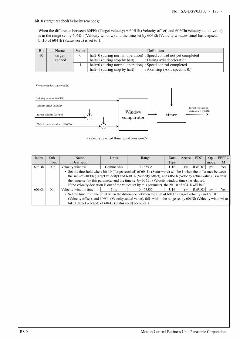
No. SX-DSV03307 - 173 -
R8.0 Motion Control Business Unit, Panasonic Corporation
bit10 (target reached(Velocity reached)): When the difference between 60FFh (Target velocity) + 60B1h (Velocity offset) and 606Ch(Velocity actual value) is in the range set by 606Dh (Velocity window) and the time set by 606Eh (Velocity window time) has elapsed, bit10 of 6041h (Statusword) is set to 1.
Bit Name Value Definition 10 target
reached 0 halt=0 (during normal operation) : Speed control not yet completed
halt=1 (during stop by halt) : During axis deceleration 1 halt=0 (during normal operation) : Speed control completed
halt=1 (during stop by halt) : Axis stop (Axis speed is 0.)
Index Sub- Index
Name / Description
Units Range Data Type
Access PDO Op- mode
EEPROM
606Dh 00h Velocity window Command/s 0 - 65535 U16 rw RxPDO pv Yes • Set the threshold where bit 10 (Target reached) of 6041h (Statusword) will be 1 when the difference between
the sum of 60FFh (Target velocity) and 60B1h (Velocity offset), and 606Ch (Velocity actual value), is within the range set by this parameter and the time set by 606Eh (Velocity window time) has elapsed. If the velocity deviation is out of the values set by this parameter, the bit 10 of 6041h will be 0.
606Eh 00h Velocity window time 1ms 0 - 65535 U16 rw RxPDO pv Yes • Set the time from the point when the difference between the sum of 60FFh (Target velocity) and 60B1h
(Velocity offset), and 606Ch (Velocity actual value), falls within the range set by 606Dh (Velocity window) to bit10 (target reached) of 6041h (Statusword) becomes 1.
Window comparator
timer
Target reached in statusword (6041h)
Velocity window time (606Eh)
<Velocity reached (functional overview)>
Target velocity (60FFh)
Velocity window (606Dh)
Velocity actual value (606Ch) -
+
Velocity offset (60B1h)
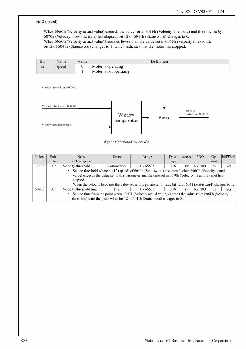
No. SX-DSV03307 - 174 -
R8.0 Motion Control Business Unit, Panasonic Corporation
bit12 (speed): When 606Ch (Velocity actual value) exceeds the value set in 606Fh (Velocity threshold) and the time set by 6070h (Velocity threshold time) has elapsed, bit 12 of 6041h (Statusword) changes to 0. When 606Ch (Velocity actual value) becomes lower than the value set in 606Fh (Velocity threshold), bit12 of 6041h (Statusword) changes to 1, which indicates that the motor has stopped.
Bit Name Value Definition 12 speed 0 Motor is operating
1 Motor is not operating
Index Sub- Index
Name / Description
Units Range Data Type
Access PDO Op- mode
EEPROM
606Fh 00h Velocity threshold Command/s 0 - 65535 U16 rw RxPDO pv Yes • Set the threshold where bit 12 (speed) of 6041h (Statusword) becomes 0 when 606Ch (Velocity actual
value) exceeds the value set to this parameter and the time set in 6070h (Velocity threshold time) has elapsed. When the velocity becomes the value set in this parameter or less, bit 12 of 6041 (Statusword) changes to 1.
6070h 00h Velocity threshold time 1ms 0 - 65535 U16 rw RxPDO pv Yes • Set the time from the point when 606Ch (Velocity actual value) exceeds the value set to 606Fh (Velocity
threshold) until the point when bit 12 of 6041h (Statusword) changes to 0.
Window comparator
timer
speed in statusword (6041h)
velocity thresold time (6070h)
<Speed (functional overview)>
Velocity actual value (606Ch)
velocity threshold (606Fh)
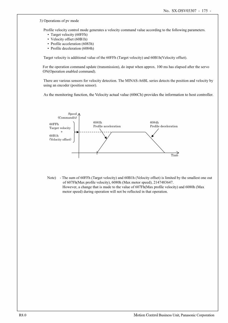
No. SX-DSV03307 - 175 -
R8.0 Motion Control Business Unit, Panasonic Corporation
3) Operations of pv mode
Profile velocity control mode generates a velocity command value according to the following parameters.
• Target velocity (60FFh) • Velocity offset (60B1h) • Profile acceleration (6083h) • Profile deceleration (6084h)
Target velocity is additional value of the 60FFh (Target velocity) and 60B1h(Velocity offset). For the operation command update (transmission), do input when approx. 100 ms has elapsed after the servo ON(Operation enabled command). There are various sensors for velocity detection. The MINAS-A6BL series detects the position and velocity by using an encoder (position sensor). As the monitoring function, the Velocity actual value (606Ch) provides the information to host controller.
Note) - The sum of 60FFh (Target velocity) and 60B1h (Velocity offset) is limited by the smallest one out
of 607Fh(Max profile velocity), 6080h (Max motor speed), 2147483647. However, a change that is made to the value of 607Fh(Max profile velocity) and 6080h (Max motor speed) during operation will not be reflected in that operation.
Time
Speed (Command/s)
6083h Profile acceleration
6084h Profile deceleration
60FFh Target velocity
+ 60B1h (Velocity offset)
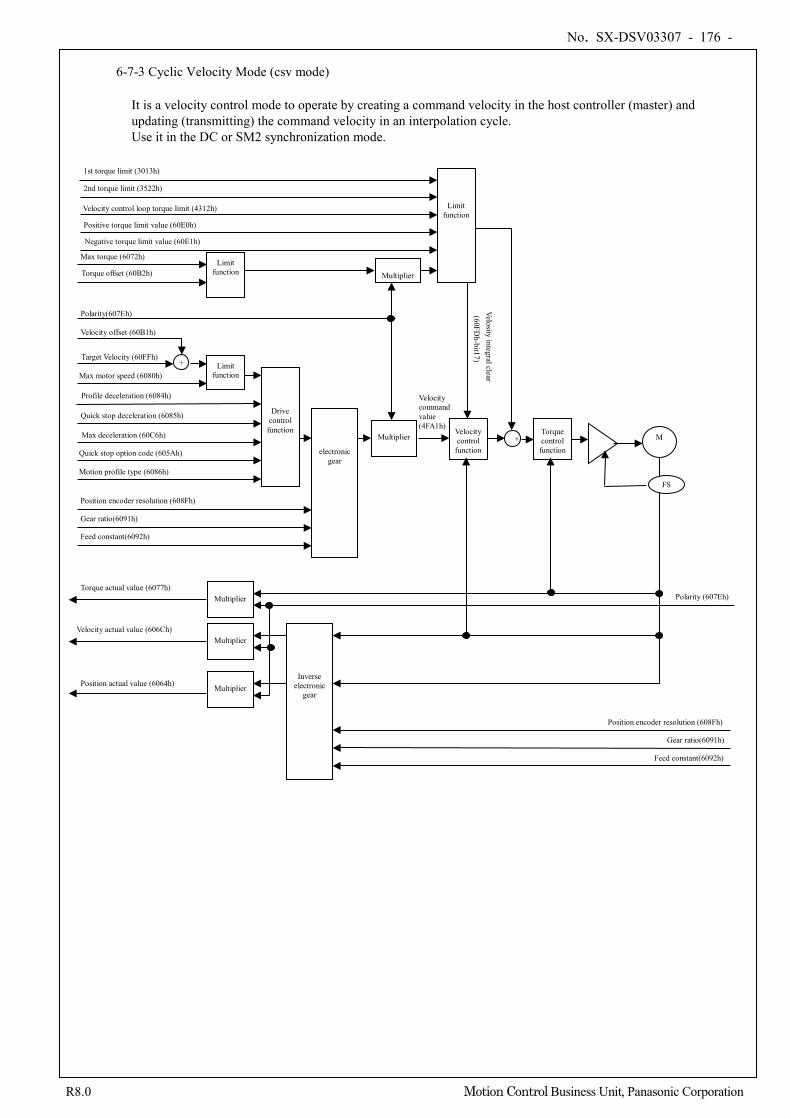
No. SX-DSV03307 - 176 -
R8.0 Motion Control Business Unit, Panasonic Corporation
6-7-3 Cyclic Velocity Mode (csv mode)
It is a velocity control mode to operate by creating a command velocity in the host controller (master) and updating (transmitting) the command velocity in an interpolation cycle. Use it in the DC or SM2 synchronization mode.
Drive control
function
+ Limit function Max motor speed (6080h)
Multiplier
Polarity(607Eh)
Quick stop deceleration (6085h)
Quick stop option code (605Ah)
Max deceleration (60C6h)
Target Velocity (60FFh)
Velocity offset (60B1h)
Velocity control
function +
Torque control
function M
FS
Feed constant(6092h)
Gear ratio(6091h)
Position encoder resolution (608Fh)
Position actual value (6064h)
Velocity actual value (606Ch)
Torque actual value (6077h) Polarity (607Eh)
Torque offset (60B2h)
Multiplier
Multiplier
Multiplier
Multiplier
Limit function
Inverse electronic
gear
electronic gear
Position encoder resolution (608Fh)
Gear ratio(6091h)
Feed constant(6092h)
Limit function
Profile deceleration (6084h)
Motion profile type (6086h)
Velocity command value (4FA1h)
Max torque (6072h)
1st torque limit (3013h)
Positive torque limit value (60E0h) Negative torque limit value (60E1h)
2nd torque limit (3522h) Velocity control loop torque limit (4312h)
Velosity integral clear (60FD
h-bit17)
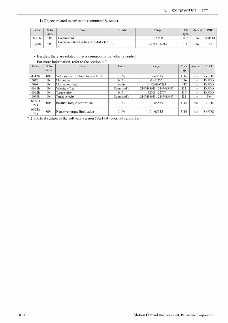
No. SX-DSV03307 - 177 -
R8.0 Motion Control Business Unit, Panasonic Corporation
1) Objects related to csv mode (command & setup)
Index Sub-
Index Name Units Range Data
Type Access PDO
6040h 00h Controlword - 0 - 65535 U16 rw RxPDO
3724h 00h Communication function extended setup 3 - -32768 - 32767 I16 rw No
• Besides, there are related objects common to the velocity control.
For more information, refer to the section 6-7-1. Index Sub-
Index Name Units Range Data
Type Access PDO
4312h 00h Velocity control loop torque limit 0.1% 0 - 65535 U16 rw RxPDO 6072h 00h Max torque 0.1% 0 - 65535 U16 rw RxPDO 6080h 00h Max motor speed r/min 0 - 4294967295 U32 rw RxPDO 60B1h 00h Velocity offset Command/s -2147483648 - 2147483647 I32 rw RxPDO 60B2h 00h Torque offset 0.1% -32768 - 32767 I16 rw RxPDO 60FFh 00h Target velocity Command/s -2147483648 - 2147483647 I32 rw No 60E0h
*1) 00h Positive torque limit value 0.1% 0 - 65535 U16 rw RxPDO
60E1h *1) 00h Negative torque limit value 0.1% 0 - 65535 U16 rw RxPDO
*1) The first edition of the software version (Ver1.04) does not support it.
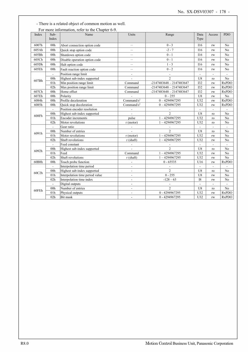
No. SX-DSV03307 - 178 -
R8.0 Motion Control Business Unit, Panasonic Corporation
- There is a related object of common motion as well.
For more information, refer to the Chapter 6-9. Index Sub-
Index Name Units Range Data
Type Access PDO
6007h 00h Abort connection option code - 0 - 3 I16 rw No 605Ah 00h Quick stop option code - -2 - 7 I16 rw No 605Bh 00h Shutdown option code - 0 - 1 I16 rw No 605Ch 00h Disable operation option code - 0 - 1 I16 rw No 605Dh 00h Halt option code - 1 - 3 I16 rw No 605Eh 00h Fault reaction option code - 0 - 2 I16 rw No
607Bh
- Position range limit - - - - - 00h Highest sub-index supported - 2 U8 ro No 01h Min position range limit Command -2147483648 – 2147483647 I32 rw RxPDO 02h Max position range limit Command -2147483648 – 2147483647 I32 rw RxPDO
607Ch 00h Home offset Command -2147483648 – 2147483647 I32 rw RxPDO 607Eh 00h Polarity - 0 – 255 U8 rw No 6084h 00h Profile deceleration Command/s2 0 – 4294967295 U32 rw RxPDO 6085h 00h Quick stop deceleration Command/s2 0 – 4294967295 U32 rw RxPDO
608Fh
- Position encoder resolution - - - - - 00h Highest sub-index supported - 2 U8 ro No 01h Encoder increments pulse 1 – 4294967295 U32 ro No 02h Motor revolutions r (motor) 1 – 4294967295 U32 ro No
6091h
- Gear ratio - - - - - 00h Number of entries - 2 U8 ro No 01h Motor revolutions r (motor) 1 – 4294967295 U32 rw No 02h Shaft revolutions r (shaft) 1 – 4294967295 U32 rw No
6092h
- Feed constant - - - - - 00h Highest sub-index supported - 2 U8 ro No 01h Feed Command 1 – 4294967295 U32 rw No 02h Shaft revolutions r (shaft) 1 – 4294967295 U32 rw No
60B8h 00h Touch probe function - 0 - 65535 U16 rw RxPDO
60C2h
- Interpolation time period - - - - - 00h Highest sub-index supported - 2 U8 ro No 01h Interpolation time period value - 0 - 255 U8 rw No 02h Interpolation time index - -128 – 63 I8 rw No
60FEh
- Digital outputs - - - - - 00h Number of entries - 2 U8 ro No 01h Physical outputs - 0 - 4294967295 U32 rw RxPDO 02h Bit mask - 0 - 4294967295 U32 rw RxPDO
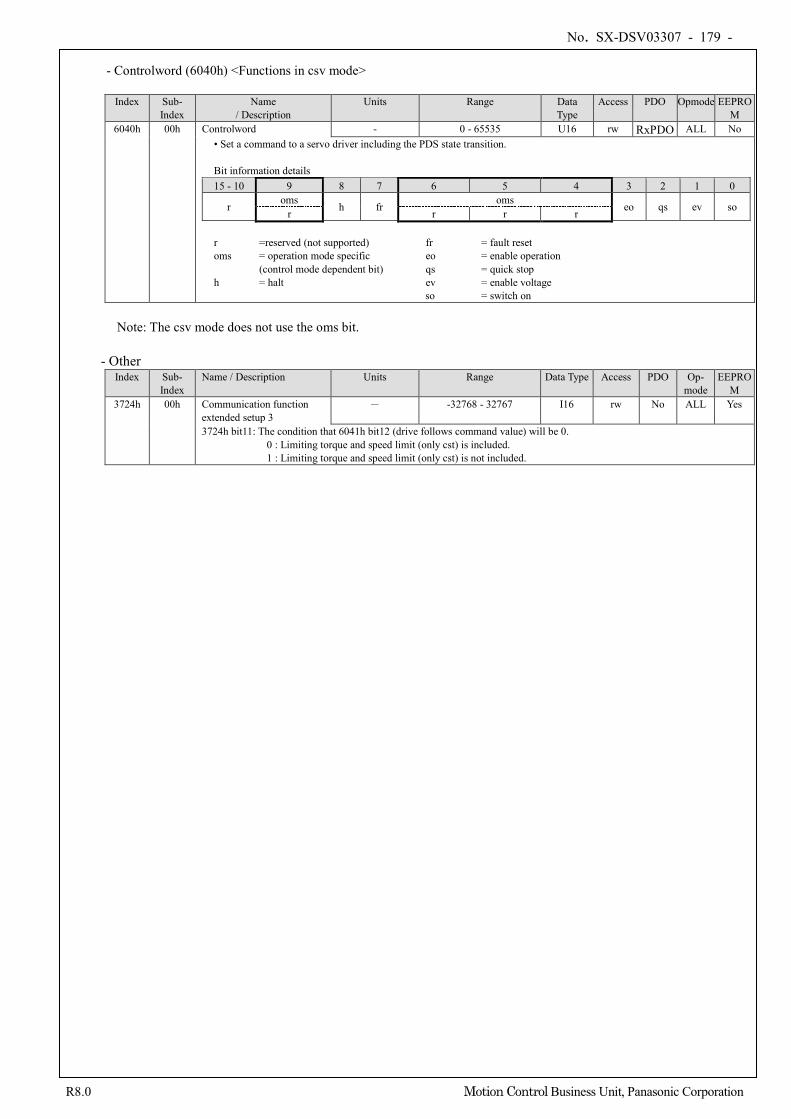
No. SX-DSV03307 - 179 -
R8.0 Motion Control Business Unit, Panasonic Corporation
- Controlword (6040h) <Functions in csv mode>
Index Sub-
Index Name
/ Description Units Range Data
Type Access PDO Opmode EEPRO
M 6040h 00h Controlword - 0 - 65535 U16 rw RxPDO ALL No
• Set a command to a servo driver including the PDS state transition. Bit information details 15 - 10 9 8 7 6 5 4 3 2 1 0
r oms h fr oms eo qs ev so r r r r
r =reserved (not supported) fr = fault reset oms = operation mode specific eo = enable operation
(control mode dependent bit) qs = quick stop h = halt ev = enable voltage
so = switch on
Note: The csv mode does not use the oms bit.
- Other Index Sub-
Index Name / Description Units Range Data Type Access PDO Op-
mode EEPRO
M 3724h 00h Communication function
extended setup 3 - -32768 - 32767 I16 rw No ALL Yes
3724h bit11: The condition that 6041h bit12 (drive follows command value) will be 0. 0 : Limiting torque and speed limit (only cst) is included. 1 : Limiting torque and speed limit (only cst) is not included.
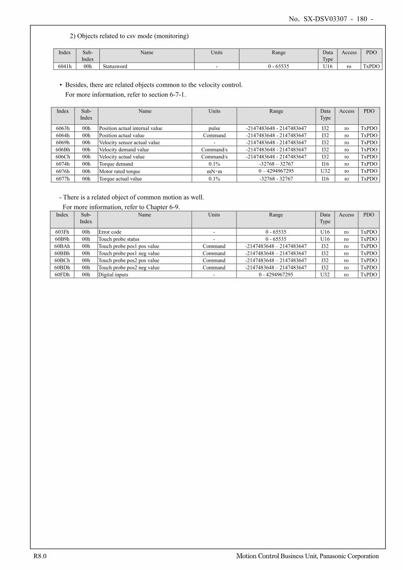
No. SX-DSV03307 - 180 -
R8.0 Motion Control Business Unit, Panasonic Corporation
2) Objects related to csv mode (monitoring)
Index Sub-
Index Name Units Range Data
Type Access PDO
6041h 00h Statusword - 0 - 65535 U16 ro TxPDO
• Besides, there are related objects common to the velocity control. For more information, refer to section 6-7-1.
Index Sub-
Index Name Units Range Data
Type Access PDO
6063h 00h Position actual internal value pulse -2147483648 - 2147483647 I32 ro TxPDO 6064h 00h Position actual value Command -2147483648 - 2147483647 I32 ro TxPDO 6069h 00h Velocity sensor actual value - -2147483648 - 2147483647 I32 ro TxPDO 606Bh 00h Velocity demand value Command/s -2147483648 - 2147483647 I32 ro TxPDO 606Ch 00h Velocity actual value Command/s -2147483648 - 2147483647 I32 ro TxPDO 6074h 00h Torque demand 0.1% -32768 – 32767 I16 ro TxPDO 6076h 00h Motor rated torque mN・m 0 – 4294967295 U32 ro TxPDO 6077h 00h Torque actual value 0.1% -32768 - 32767 I16 ro TxPDO
- There is a related object of common motion as well.
For more information, refer to Chapter 6-9. Index Sub-
Index Name Units Range Data
Type Access PDO
603Fh 00h Error code - 0 - 65535 U16 ro TxPDO 60B9h 00h Touch probe status - 0 - 65535 U16 ro TxPDO 60BAh 00h Touch probe pos1 pos value Command -2147483648 – 2147483647 I32 ro TxPDO 60BBh 00h Touch probe pos1 neg value Command -2147483648 – 2147483647 I32 ro TxPDO 60BCh 00h Touch probe pos2 pos value Command -2147483648 – 2147483647 I32 ro TxPDO 60BDh 00h Touch probe pos2 neg value Command -2147483648 – 2147483647 I32 ro TxPDO 60FDh 00h Digital inputs - 0 - 4294967295 U32 ro TxPDO

No. SX-DSV03307 - 181 -
R8.0 Motion Control Business Unit, Panasonic Corporation
- Statusword (6041h) <Functions in csv mode>
Index Sub-
Index Name
/ Description Units Range Data
Type Access PDO Opmode EEPROM
6041h 00h Statusword - 0 - 65535 U16 ro TxPDO ALL No • Displays the servo driver state. Bit information details
15 - 14 13 12 11 10 9 8 7 6 5 4 3 2 1 0
r oms
ila oms
rm r w sod qs ve f oe so rtso r drive follows
command value r
r = reserved(not supported) w = warning sod = switch on disabled oms = operation mode specific qs = quick stop (control mode dependent bit) ve = voltage enabled ila = internal limit active f = fault oe = operation enabled rm = remote so = switched on r = reserved(not supported) rtso = ready to switch on
bit13,12,10(operation mode specific): bit Name Value Definition 10 reserved - Not used
12 drive follows
command value
0 Operation is not performed according to the target velocity. *1) 1 Operation is performed according to the target velocity. *1)
13 reserved - Not used
*1) “Operation is performed according to the target velocity” refers to cases where the following conditions are all satisfied:
- PDS state is Operation enabled - While not in deceleration (Halt, POT/NOT, Quickstop, Shutdown, Disable operation and Fault) - While not in Halt status - POT not detected when a positive direction operation command is in process, or NOT not detected
when a negative direction operation command is in process - Torque limit has not occurred(Valid only when this condition 3724h-bit11 is 0) - Not during magnet pole position estimation
Index Sub- Index
Name / Description Units Range Data Type Access PDO Op- mode
EEPROM
3724h 00h Communication function extended setup 3
- -32768 - 32767 I16 rw No ALL Yes
3724h bit11: The condition that 6041h bit12 (drive follows command value) will be 0. 0 : Limiting torque and speed limit (only cst) is included. 1 : Limiting torque and speed limit (only cst) is not included.
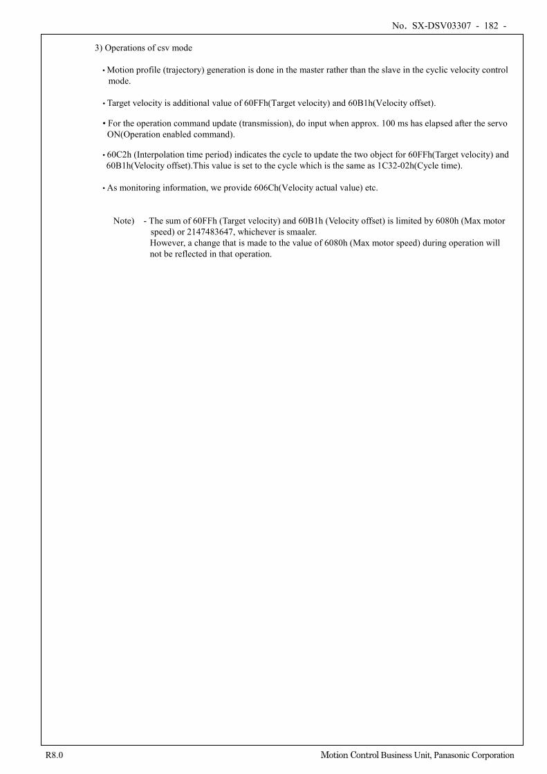
No. SX-DSV03307 - 182 -
R8.0 Motion Control Business Unit, Panasonic Corporation
3) Operations of csv mode • Motion profile (trajectory) generation is done in the master rather than the slave in the cyclic velocity control
mode. • Target velocity is additional value of 60FFh(Target velocity) and 60B1h(Velocity offset). • For the operation command update (transmission), do input when approx. 100 ms has elapsed after the servo
ON(Operation enabled command). • 60C2h (Interpolation time period) indicates the cycle to update the two object for 60FFh(Target velocity) and 60B1h(Velocity offset).This value is set to the cycle which is the same as 1C32-02h(Cycle time).
• As monitoring information, we provide 606Ch(Velocity actual value) etc.
Note) - The sum of 60FFh (Target velocity) and 60B1h (Velocity offset) is limited by 6080h (Max motor speed) or 2147483647, whichever is smaaler. However, a change that is made to the value of 6080h (Max motor speed) during operation will not be reflected in that operation.
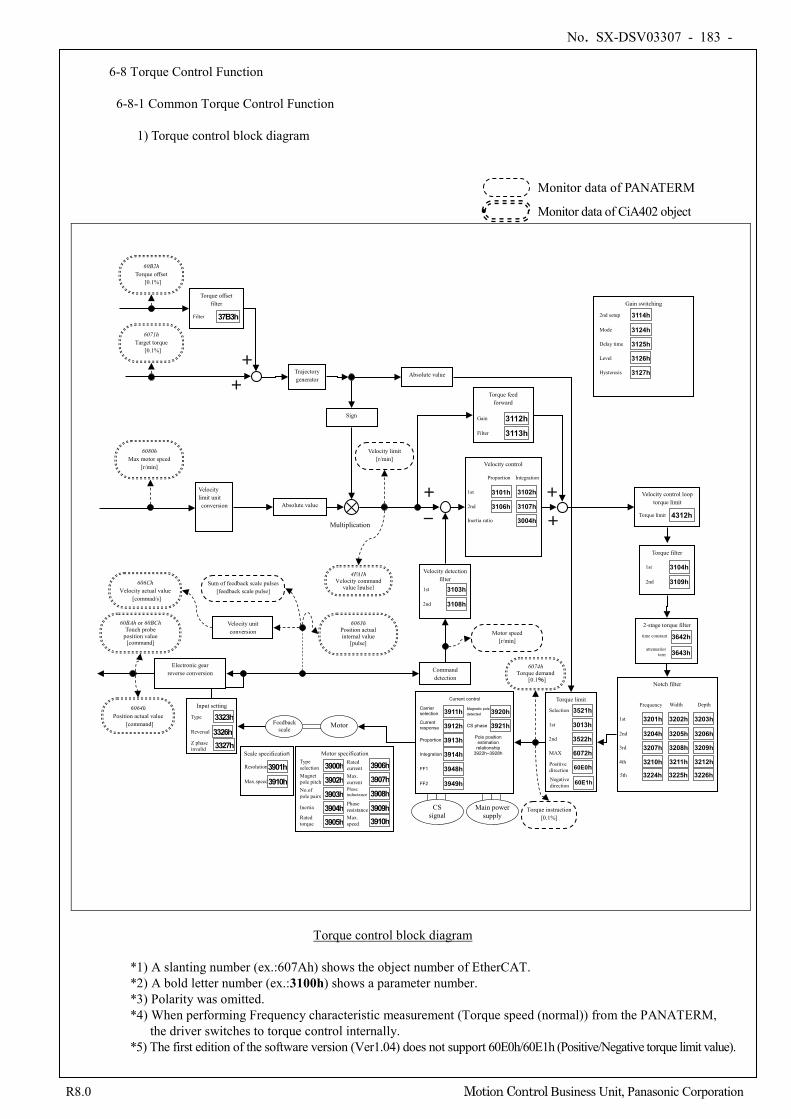
No. SX-DSV03307 - 183 -
R8.0 Motion Control Business Unit, Panasonic Corporation
6-8 Torque Control Function
6-8-1 Common Torque Control Function
1) Torque control block diagram
+
-
Command detection
Gain switching
2nd setup 3114h
Mode 3124h
Delay time 3125h
Level 3126h
Hysteresis 3127h
Velocity detection filter
1st 3103h
2nd 3108h
Velocity control
3102h
3107h
Proportion Integration
Inertia ratio
1st 3101h
2nd 3106h
3004h
Sign
Absolute value
6064h Position actual value
[command]
60BAh or 60BCh Touch probe
position value [command]
Electronic gear reverse conversion
6063h Position actual internal value
[pulse]
606Ch Velocity actual value
[commad/s]
60B2h Torque offset
[0.1%]
6080h Max motor speed
[r/min]
Velocity limit unit conversion Absolute value
Multiplication
+
+
6071h Target torque
[0.1%]
Motor speed [r/min]
Velocity limit [r/min]
Sum of feedback scale pulses [feedback scale pulse]
Notch filter
3203h
3206h
3209h
3212h
Depth
3202h
3205h
3208h
3211h
Width
1st 3201h
2nd 3204h 3rd 3207h
4th 3210h
Frequency
Torque filter
1st 3104h
2nd 3109h
2-stage torque filter
3642h
3643h
time constant
attenuation term
5th 3226h 3225h 3224h
Velocity unit conversion
4FA1h Velocity command
value [pulse]
Trajectory generator
Torque offset filter
Filter 37B3h
Velocity control loop torque limit
Torque limit 4312h
6074h Torque demand
[0.1%]
Torque instruction [0.1%]
Torque limit
Selection 3521h
MAX 6072h
1st 3013h
2nd 3522h
Positive direction 60E0h Negative direction 60E1h
CS signal
Main power supply
Current control
Current response 3912h
Proportion 3913h
Carrier selection 3911h
Integration 3914h
Magnetic pole detected 3920h
CS phase 3921h
Pole position estimation relationship
3922h–3928h
FF1 3948h
FF2 3949h
Feedback scale
Motor
Input setting
3326h Reversal
Type 3323h
Z phase invalid 3327h
Scale specification
Resolution 3901h Max.speed 3910h
Motor specification
Magnet pole pitch No.of pole pairs
Type selection
Inertia
Rated torque
Rated current Max. current
Max. speed
Phase inductance
Phase resistance
3900h 3902h 3903h 3904h 3905h
3906h 3907h 3908h 3909h 3910h
Torque feed forward
Gain 3112h Filter 3113h
+
+
Torque control block diagram
*1) A slanting number (ex.:607Ah) shows the object number of EtherCAT. *2) A bold letter number (ex.:3100h) shows a parameter number. *3) Polarity was omitted. *4) When performing Frequency characteristic measurement (Torque speed (normal)) from the PANATERM,
the driver switches to torque control internally. *5) The first edition of the software version (Ver1.04) does not support 60E0h/60E1h (Positive/Negative torque limit value).
Monitor data of PANATERM Monitor data of CiA402 object
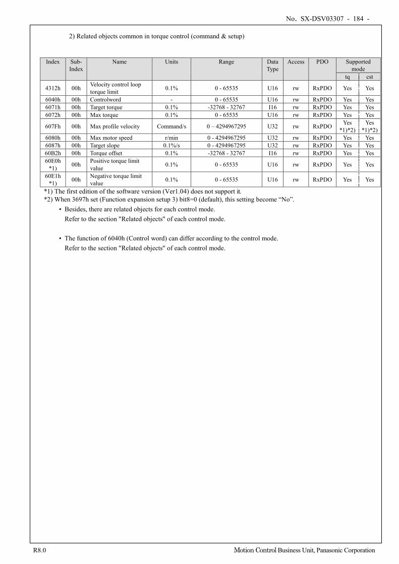
No. SX-DSV03307 - 184 -
R8.0 Motion Control Business Unit, Panasonic Corporation
2) Related objects common in torque control (command & setup)
Index Sub- Index
Name Units Range Data Type
Access PDO Supported mode
tq cst
4312h 00h Velocity control loop torque limit 0.1% 0 - 65535 U16 rw RxPDO Yes Yes
6040h 00h Controlword - 0 - 65535 U16 rw RxPDO Yes Yes 6071h 00h Target torque 0.1% -32768 - 32767 I16 rw RxPDO Yes Yes 6072h 00h Max torque 0.1% 0 - 65535 U16 rw RxPDO Yes Yes
607Fh 00h Max profile velocity Command/s 0 – 4294967295 U32 rw RxPDO Yes *1)*2)
Yes *1)*2)
6080h 00h Max motor speed r/min 0 - 4294967295 U32 rw RxPDO Yes Yes 6087h 00h Target slope 0.1%/s 0 - 4294967295 U32 rw RxPDO Yes Yes 60B2h 00h Torque offset 0.1% -32768 - 32767 I16 rw RxPDO Yes Yes 60E0h
*1) 00h Positive torque limit value 0.1% 0 - 65535 U16 rw RxPDO Yes Yes
60E1h *1) 00h Negative torque limit
value 0.1% 0 - 65535 U16 rw RxPDO Yes Yes
*1) The first edition of the software version (Ver1.04) does not support it. *2) When 3697h set (Function expansion setup 3) bit8=0 (default), this setting become “No”.
• Besides, there are related objects for each control mode. Refer to the section "Related objects" of each control mode.
• The function of 6040h (Control word) can differ according to the control mode.
Refer to the section "Related objects" of each control mode.
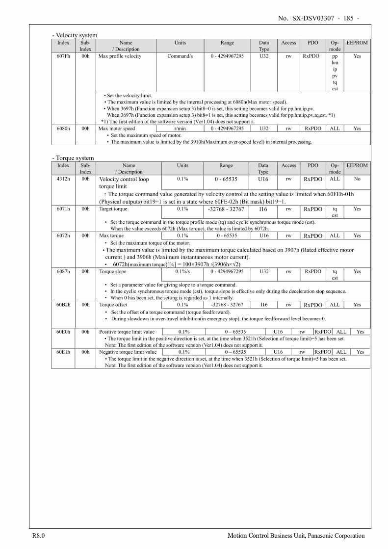
No. SX-DSV03307 - 185 -
R8.0 Motion Control Business Unit, Panasonic Corporation
- Velocity system
Index Sub- Index
Name / Description
Units Range Data Type
Access PDO Op- mode
EEPROM
607Fh 00h Max profile velocity Command/s 0 - 4294967295 U32 rw RxPDO pp hm ip pv tq cst
Yes
• Set the velocity limit. • The maximum value is limited by the internal processing at 6080h(Max motor speed). • When 3697h (Function expansion setup 3) bit8=0 is set, this setting becomes valid for pp,hm,ip,pv.
When 3697h (Function expansion setup 3) bit8=1 is set, this setting becomes valid for pp,hm,ip,pv,tq,cst. *1) *1) The first edition of the software version (Ver1.04) does not support it.
6080h 00h Max motor speed r/min 0 - 4294967295 U32 rw RxPDO ALL Yes • Set the maximum speed of motor. • The maximum value is limited by the 3910h(Maximum over-speed level) in internal processing.
- Torque system
Index Sub- Index
Name / Description
Units Range Data Type
Access PDO Op- mode
EEPROM
4312h 00h Velocity control loop torque limit
0.1% 0 - 65535 U16 rw RxPDO ALL No
・The torque command value generated by velocity control at the setting value is limited when 60FEh-01h (Physical outputs) bit19=1 is set in a state where 60FE-02h (Bit mask) bit19=1.
6071h 00h Target torque 0.1% -32768 - 32767 I16 rw RxPDO tq cst
Yes
• Set the torque command in the torque profile mode (tq) and cyclic synchronous torque mode (cst). When the value exceeds 6072h (Max torque), the value is limited by 6072h.
6072h 00h Max torque 0.1% 0 - 65535 U16 rw RxPDO ALL Yes • Set the maximum torque of the motor.
• The maximum value is limited by the maximum torque calculated based on 3907h (Rated effective motor current ) and 3906h (Maximum instantaneous motor current). • 6072h(maximum torque)[%] = 100×3907h /(3906h×√2)
6087h 00h Torque slope 0.1%/s 0 - 4294967295 U32 rw RxPDO tq cst
Yes
• Set a parameter value for giving slope to a torque command. • In the cyclic synchronous torque mode (cst), torque slope is effective only during the deceleration stop sequence. • When 0 has been set, the setting is regarded as 1 internally.
60B2h 00h Torque offset 0.1% -32768 - 32767 I16 rw RxPDO ALL Yes • Set the offset of a torque command (torque feedforward). • During slowdown in over-travel inhibition(in emergncy stop), the torque feedforward level becomes 0.
60E0h 00h Positive torque limit value 0.1% 0 – 65535 U16 rw RxPDO ALL Yes • The torque limit in the positive direction is set, at the time when 3521h (Selection of torque limit)=5 has been set. Note: The first edition of the software version (Ver1.04) does not support it.
60E1h 00h Negative torque limit value 0.1% 0 – 65535 U16 rw RxPDO ALL Yes • The torque limit in the negative direction is set, at the time when 3521h (Selection of torque limit)=5 has been set. Note: The first edition of the software version (Ver1.04) does not support it.
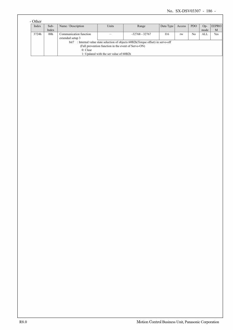
No. SX-DSV03307 - 186 -
R8.0 Motion Control Business Unit, Panasonic Corporation
- Other
Index Sub- Index
Name / Description Units Range Data Type Access PDO Op- mode
EEPROM
3724h 00h Communication function extended setup 3
- -32768 - 32767 I16 rw No ALL Yes
bit7 : Internal value state selection of objects 60B2h(Torque offset) in servo-off (Fall prevention function in the event of Servo-ON) 0: Clear 1: Updated with the set value of 60B2h
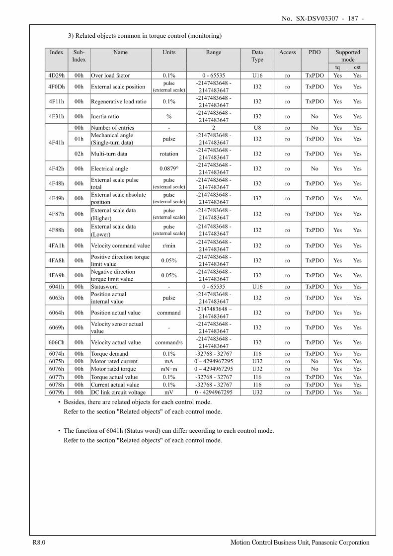
No. SX-DSV03307 - 187 -
R8.0 Motion Control Business Unit, Panasonic Corporation
3) Related objects common in torque control (monitoring)
Index Sub-
Index Name Units Range Data
Type Access PDO Supported
mode tq cst
4D29h 00h Over load factor 0.1% 0 - 65535 U16 ro TxPDO Yes Yes
4F0Dh 00h External scale position pulse (external scale)
-2147483648 - 2147483647 I32 ro TxPDO Yes Yes
4F11h 00h Regenerative load ratio 0.1% -2147483648 - 2147483647 I32 ro TxPDO Yes Yes
4F31h 00h Inertia ratio % -2147483648 - 2147483647 I32 ro No Yes Yes
4F41h
00h Number of entries - 2 U8 ro No Yes Yes
01h Mechanical angle (Single-turn data) pulse -2147483648 -
2147483647 I32 ro TxPDO Yes Yes
02h Multi-turn data rotation -2147483648 - 2147483647 I32 ro TxPDO Yes Yes
4F42h 00h Electrical angle 0.0879° -2147483648 - 2147483647 I32 ro No Yes Yes
4F48h 00h External scale pulse total
pulse (external scale)
-2147483648 - 2147483647 I32 ro TxPDO Yes Yes
4F49h 00h External scale absolute position
pulse (external scale)
-2147483648 - 2147483647 I32 ro TxPDO Yes Yes
4F87h 00h External scale data (Higher)
pulse (external scale)
-2147483648 - 2147483647 I32 ro TxPDO Yes Yes
4F88h 00h External scale data (Lower)
pulse (external scale)
-2147483648 - 2147483647 I32 ro TxPDO Yes Yes
4FA1h 00h Velocity command value r/min -2147483648 - 2147483647 I32 ro TxPDO Yes Yes
4FA8h 00h Positive direction torque limit value 0.05% -2147483648 -
2147483647 I32 ro TxPDO Yes Yes
4FA9h 00h Negative direction torque limit value 0.05% -2147483648 -
2147483647 I32 ro TxPDO Yes Yes
6041h 00h Statusword - 0 - 65535 U16 ro TxPDO Yes Yes
6063h 00h Position actual internal value pulse -2147483648 -
2147483647 I32 ro TxPDO Yes Yes
6064h 00h Position actual value command -2147483648 – 2147483647 I32 ro TxPDO Yes Yes
6069h 00h Velocity sensor actual value - -2147483648 -
2147483647 I32 ro TxPDO Yes Yes
606Ch 00h Velocity actual value command/s -2147483648 - 2147483647 I32 ro TxPDO Yes Yes
6074h 00h Torque demand 0.1% -32768 - 32767 I16 ro TxPDO Yes Yes 6075h 00h Motor rated current mA 0 – 4294967295 U32 ro No Yes Yes 6076h 00h Motor rated torque mN・m 0 – 4294967295 U32 ro No Yes Yes 6077h 00h Torque actual value 0.1% -32768 - 32767 I16 ro TxPDO Yes Yes 6078h 00h Current actual value 0.1% -32768 - 32767 I16 ro TxPDO Yes Yes 6079h 00h DC link circuit voltage mV 0 - 4294967295 U32 ro TxPDO Yes Yes
• Besides, there are related objects for each control mode. Refer to the section "Related objects" of each control mode.
• The function of 6041h (Status word) can differ according to each control mode.
Refer to the section "Related objects" of each control mode.
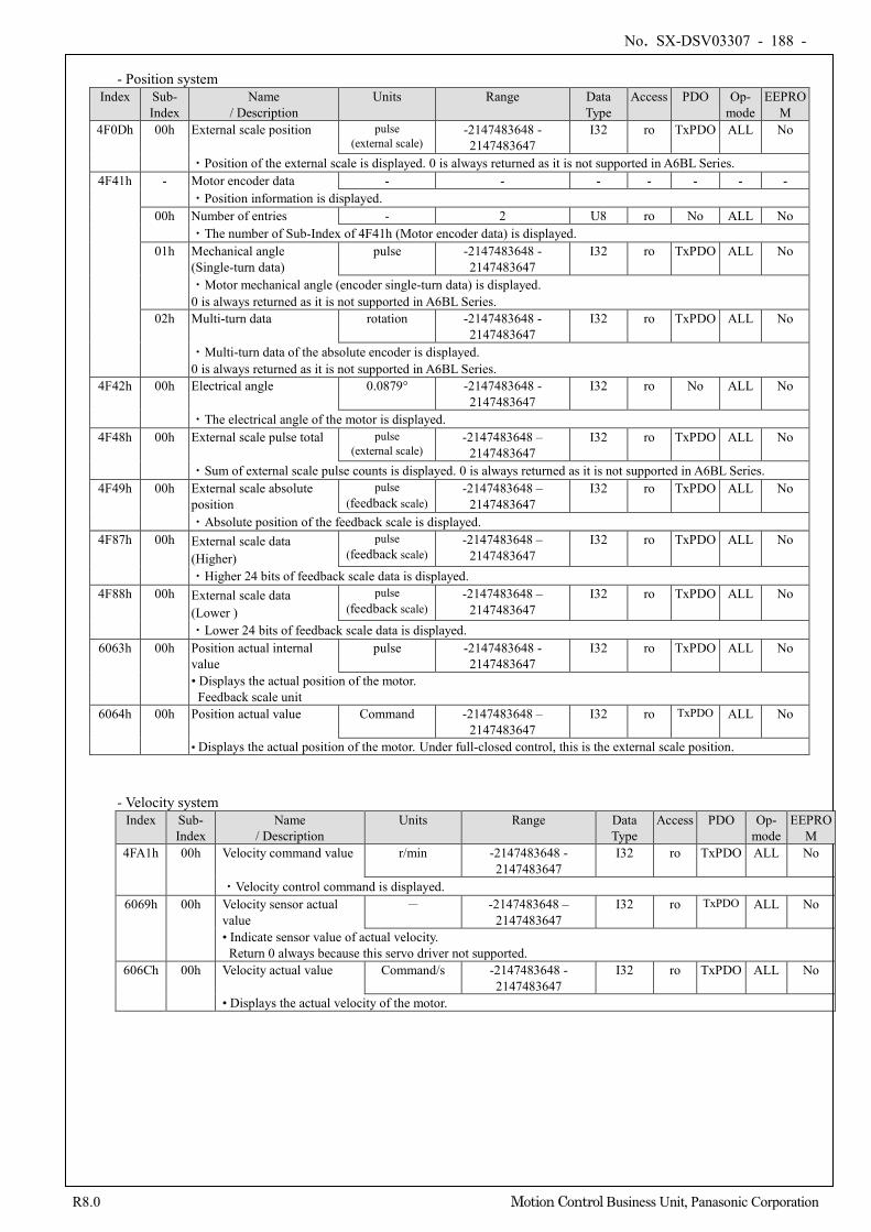
No. SX-DSV03307 - 188 -
R8.0 Motion Control Business Unit, Panasonic Corporation
- Position system
Index Sub- Index
Name / Description
Units Range Data Type
Access PDO Op- mode
EEPROM
4F0Dh 00h External scale position pulse (external scale)
-2147483648 - 2147483647
I32 ro TxPDO ALL No
・Position of the external scale is displayed. 0 is always returned as it is not supported in A6BL Series. 4F41h - Motor encoder data - - - - - - -
・Position information is displayed. 00h Number of entries - 2 U8 ro No ALL No
・The number of Sub-Index of 4F41h (Motor encoder data) is displayed. 01h Mechanical angle
(Single-turn data) pulse -2147483648 -
2147483647 I32 ro TxPDO ALL No
・Motor mechanical angle (encoder single-turn data) is displayed. 0 is always returned as it is not supported in A6BL Series.
02h Multi-turn data rotation -2147483648 - 2147483647
I32 ro TxPDO ALL No
・Multi-turn data of the absolute encoder is displayed. 0 is always returned as it is not supported in A6BL Series.
4F42h 00h Electrical angle 0.0879° -2147483648 - 2147483647
I32 ro No ALL No
・The electrical angle of the motor is displayed. 4F48h 00h External scale pulse total pulse
(external scale) -2147483648 –
2147483647 I32 ro TxPDO ALL No
・Sum of external scale pulse counts is displayed. 0 is always returned as it is not supported in A6BL Series. 4F49h 00h External scale absolute
position pulse
(feedback scale) -2147483648 –
2147483647 I32 ro TxPDO ALL No
・Absolute position of the feedback scale is displayed. 4F87h 00h External scale data
(Higher) pulse
(feedback scale) -2147483648 –
2147483647 I32 ro TxPDO ALL No
・Higher 24 bits of feedback scale data is displayed. 4F88h 00h External scale data
(Lower ) pulse
(feedback scale) -2147483648 –
2147483647 I32 ro TxPDO ALL No
・Lower 24 bits of feedback scale data is displayed. 6063h 00h Position actual internal
value pulse -2147483648 -
2147483647 I32 ro TxPDO ALL No
• Displays the actual position of the motor. Feedback scale unit
6064h 00h Position actual value Command -2147483648 – 2147483647
I32 ro TxPDO ALL No
• Displays the actual position of the motor. Under full-closed control, this is the external scale position.
- Velocity system Index Sub-
Index Name
/ Description Units Range Data
Type Access PDO Op-
mode EEPRO
M 4FA1h 00h Velocity command value r/min -2147483648 -
2147483647 I32 ro TxPDO ALL No
・Velocity control command is displayed. 6069h 00h Velocity sensor actual
value - -2147483648 –
2147483647 I32 ro TxPDO ALL No
• Indicate sensor value of actual velocity. Return 0 always because this servo driver not supported.
606Ch 00h Velocity actual value Command/s -2147483648 - 2147483647
I32 ro TxPDO ALL No
• Displays the actual velocity of the motor.
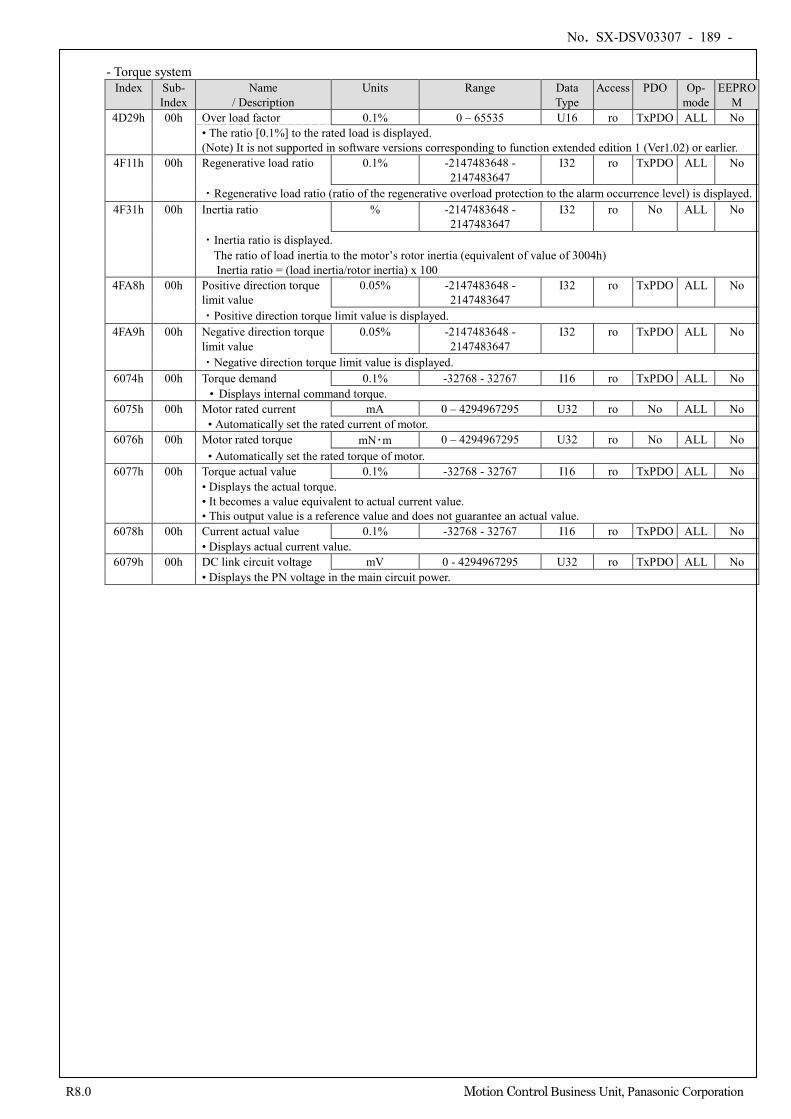
No. SX-DSV03307 - 189 -
R8.0 Motion Control Business Unit, Panasonic Corporation
- Torque system
Index Sub- Index
Name / Description
Units Range Data Type
Access PDO Op- mode
EEPROM
4D29h 00h Over load factor 0.1% 0 – 65535 U16 ro TxPDO ALL No • The ratio [0.1%] to the rated load is displayed. (Note) It is not supported in software versions corresponding to function extended edition 1 (Ver1.02) or earlier.
4F11h 00h Regenerative load ratio 0.1% -2147483648 - 2147483647
I32 ro TxPDO ALL No
・Regenerative load ratio (ratio of the regenerative overload protection to the alarm occurrence level) is displayed. 4F31h 00h Inertia ratio % -2147483648 -
2147483647 I32 ro No ALL No
・Inertia ratio is displayed. The ratio of load inertia to the motor’s rotor inertia (equivalent of value of 3004h) Inertia ratio = (load inertia/rotor inertia) x 100
4FA8h 00h Positive direction torque limit value
0.05% -2147483648 - 2147483647
I32 ro TxPDO ALL No
・Positive direction torque limit value is displayed. 4FA9h 00h Negative direction torque
limit value 0.05% -2147483648 -
2147483647 I32 ro TxPDO ALL No
・Negative direction torque limit value is displayed. 6074h 00h Torque demand 0.1% -32768 - 32767 I16 ro TxPDO ALL No
• Displays internal command torque. 6075h 00h Motor rated current mA 0 – 4294967295 U32 ro No ALL No
• Automatically set the rated current of motor. 6076h 00h Motor rated torque mN・m 0 – 4294967295 U32 ro No ALL No
• Automatically set the rated torque of motor. 6077h 00h Torque actual value 0.1% -32768 - 32767 I16 ro TxPDO ALL No
• Displays the actual torque. • It becomes a value equivalent to actual current value. • This output value is a reference value and does not guarantee an actual value.
6078h 00h Current actual value 0.1% -32768 - 32767 I16 ro TxPDO ALL No • Displays actual current value.
6079h 00h DC link circuit voltage mV 0 - 4294967295 U32 ro TxPDO ALL No • Displays the PN voltage in the main circuit power.
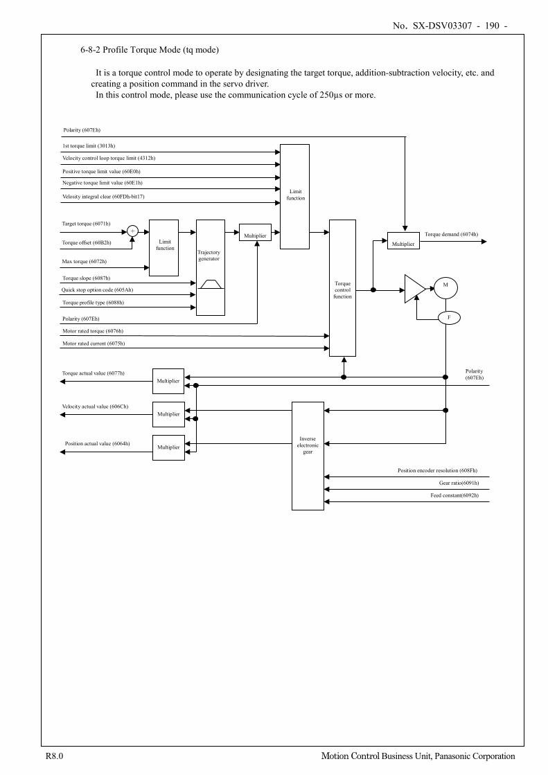
No. SX-DSV03307 - 190 -
R8.0 Motion Control Business Unit, Panasonic Corporation
6-8-2 Profile Torque Mode (tq mode)
It is a torque control mode to operate by designating the target torque, addition-subtraction velocity, etc. and creating a position command in the servo driver.
In this control mode, please use the communication cycle of 250µs or more.
Torque control
function
M
F
Polarity (607Eh)
Trajectory generator
Multiplier
Max torque (6072h)
Torque offset (60B2h)
Torque actual value (6077h)
Velocity actual value (606Ch)
Multiplier Position actual value (6064h)
Multiplier
Multiplier
Polarity (607Eh)
Inverse electronic
gear
Feed constant(6092h)
Gear ratio(6091h)
Position encoder resolution (608Fh)
Torque profile type (6088h)
Torque slope (6087h)
Limit function
Target torque (6071h) +
Motor rated current (6075h)
Motor rated torque (6076h)
Torque demand (6074h)
Limit function
1st torque limit (3013h)
Multiplier
Polarity (607Eh)
Quick stop option code (605Ah)
Velocity control loop torque limit (4312h)
Positive torque limit value (60E0h)
Negative torque limit value (60E1h)
Velosity integral clear (60FDh-bit17)
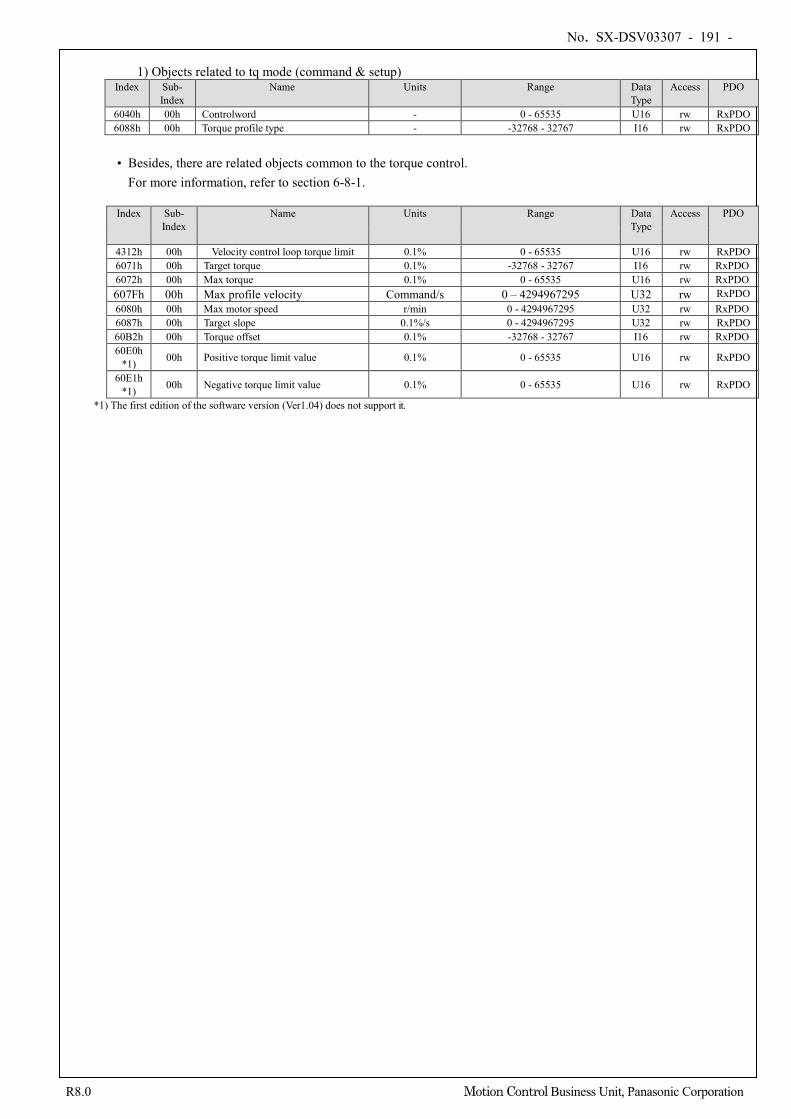
No. SX-DSV03307 - 191 -
R8.0 Motion Control Business Unit, Panasonic Corporation
1) Objects related to tq mode (command & setup)
Index Sub- Index
Name Units Range Data Type
Access PDO
6040h 00h Controlword - 0 - 65535 U16 rw RxPDO 6088h 00h Torque profile type - -32768 - 32767 I16 rw RxPDO
• Besides, there are related objects common to the torque control.
For more information, refer to section 6-8-1.
Index Sub- Index
Name Units Range Data Type
Access PDO
4312h 00h Velocity control loop torque limit 0.1% 0 - 65535 U16 rw RxPDO 6071h 00h Target torque 0.1% -32768 - 32767 I16 rw RxPDO 6072h 00h Max torque 0.1% 0 - 65535 U16 rw RxPDO 607Fh 00h Max profile velocity Command/s 0 – 4294967295 U32 rw RxPDO 6080h 00h Max motor speed r/min 0 - 4294967295 U32 rw RxPDO 6087h 00h Target slope 0.1%/s 0 - 4294967295 U32 rw RxPDO 60B2h 00h Torque offset 0.1% -32768 - 32767 I16 rw RxPDO 60E0h
*1) 00h Positive torque limit value 0.1% 0 - 65535 U16 rw RxPDO
60E1h *1) 00h Negative torque limit value 0.1% 0 - 65535 U16 rw RxPDO
*1) The first edition of the software version (Ver1.04) does not support it.
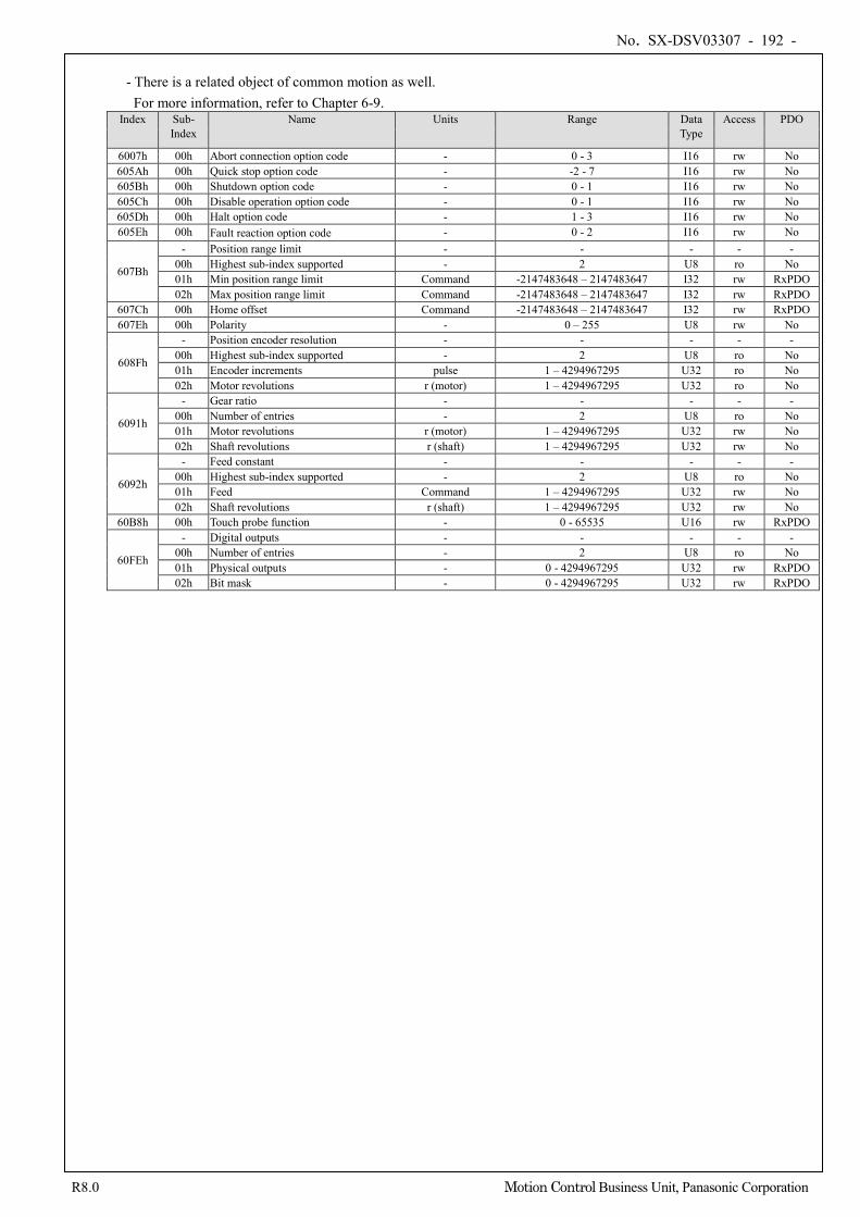
No. SX-DSV03307 - 192 -
R8.0 Motion Control Business Unit, Panasonic Corporation
- There is a related object of common motion as well.
For more information, refer to Chapter 6-9. Index Sub-
Index Name Units Range Data
Type Access PDO
6007h 00h Abort connection option code - 0 - 3 I16 rw No 605Ah 00h Quick stop option code - -2 - 7 I16 rw No 605Bh 00h Shutdown option code - 0 - 1 I16 rw No 605Ch 00h Disable operation option code - 0 - 1 I16 rw No 605Dh 00h Halt option code - 1 - 3 I16 rw No 605Eh 00h Fault reaction option code - 0 - 2 I16 rw No
607Bh
- Position range limit - - - - - 00h Highest sub-index supported - 2 U8 ro No 01h Min position range limit Command -2147483648 – 2147483647 I32 rw RxPDO 02h Max position range limit Command -2147483648 – 2147483647 I32 rw RxPDO
607Ch 00h Home offset Command -2147483648 – 2147483647 I32 rw RxPDO 607Eh 00h Polarity - 0 – 255 U8 rw No
608Fh
- Position encoder resolution - - - - - 00h Highest sub-index supported - 2 U8 ro No 01h Encoder increments pulse 1 – 4294967295 U32 ro No 02h Motor revolutions r (motor) 1 – 4294967295 U32 ro No
6091h
- Gear ratio - - - - - 00h Number of entries - 2 U8 ro No 01h Motor revolutions r (motor) 1 – 4294967295 U32 rw No 02h Shaft revolutions r (shaft) 1 – 4294967295 U32 rw No
6092h
- Feed constant - - - - - 00h Highest sub-index supported - 2 U8 ro No 01h Feed Command 1 – 4294967295 U32 rw No 02h Shaft revolutions r (shaft) 1 – 4294967295 U32 rw No
60B8h 00h Touch probe function - 0 - 65535 U16 rw RxPDO
60FEh
- Digital outputs - - - - - 00h Number of entries - 2 U8 ro No 01h Physical outputs - 0 - 4294967295 U32 rw RxPDO 02h Bit mask - 0 - 4294967295 U32 rw RxPDO
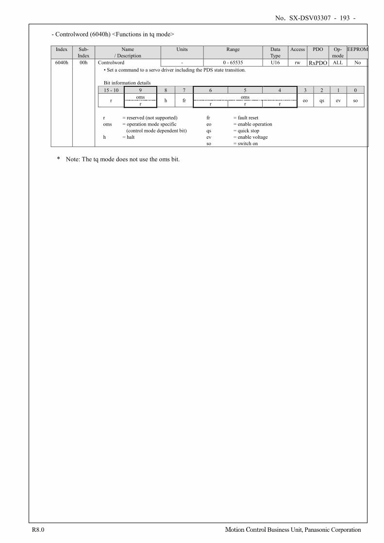
No. SX-DSV03307 - 193 -
R8.0 Motion Control Business Unit, Panasonic Corporation
- Controlword (6040h) <Functions in tq mode>
Index Sub-
Index Name
/ Description Units Range Data
Type Access PDO Op-
mode EEPROM
6040h 00h Controlword - 0 - 65535 U16 rw RxPDO ALL No • Set a command to a servo driver including the PDS state transition. Bit information details 15 - 10 9 8 7 6 5 4 3 2 1 0
r oms h fr oms eo qs ev so r r r r
r = reserved (not supported) fr = fault reset oms = operation mode specific eo = enable operation
(control mode dependent bit) qs = quick stop h = halt ev = enable voltage so = switch on
* Note: The tq mode does not use the oms bit.
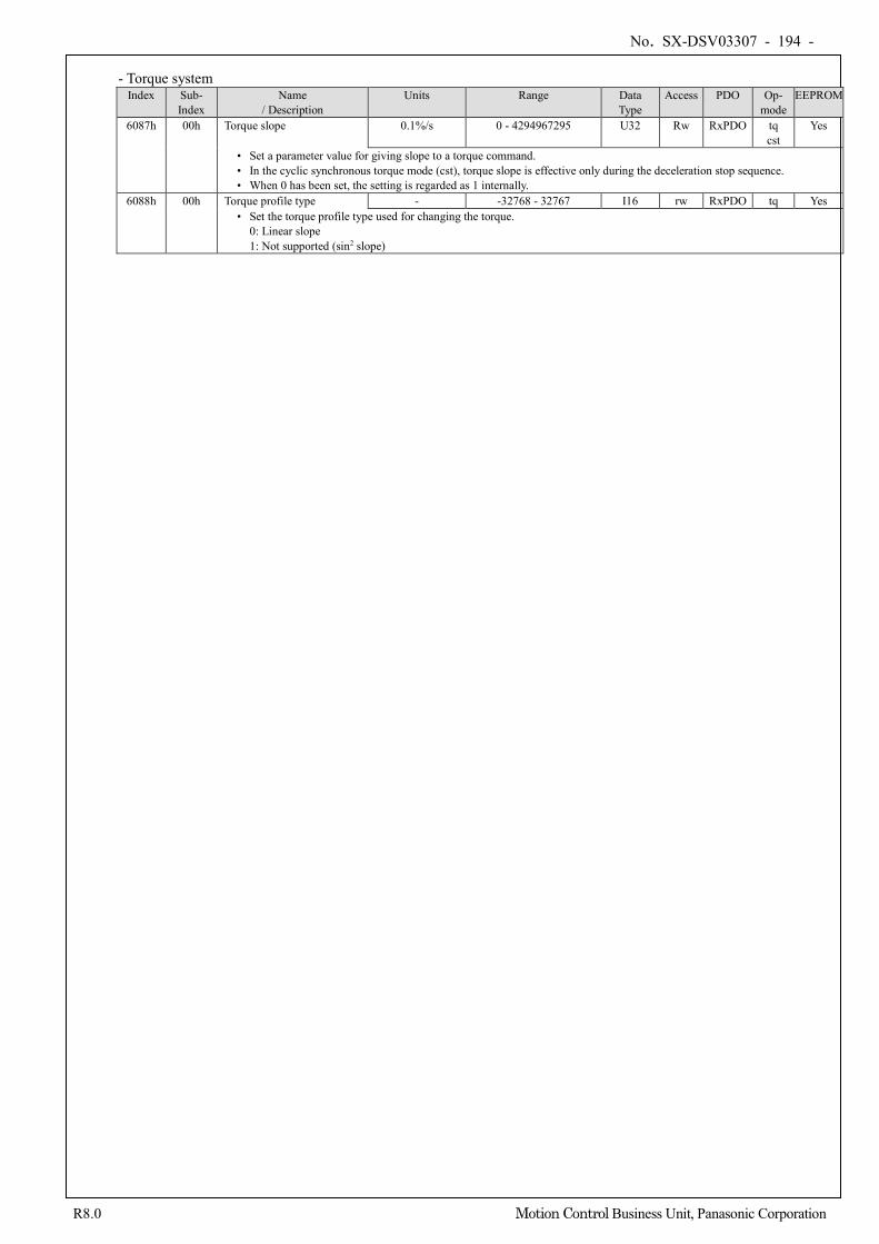
No. SX-DSV03307 - 194 -
R8.0 Motion Control Business Unit, Panasonic Corporation
- Torque system
Index Sub- Index
Name / Description
Units Range Data Type
Access PDO Op- mode
EEPROM
6087h 00h Torque slope 0.1%/s 0 - 4294967295 U32 Rw RxPDO tq cst
Yes
• Set a parameter value for giving slope to a torque command. • In the cyclic synchronous torque mode (cst), torque slope is effective only during the deceleration stop sequence. • When 0 has been set, the setting is regarded as 1 internally.
6088h 00h Torque profile type - -32768 - 32767 I16 rw RxPDO tq Yes • Set the torque profile type used for changing the torque.
0: Linear slope 1: Not supported (sin2 slope)
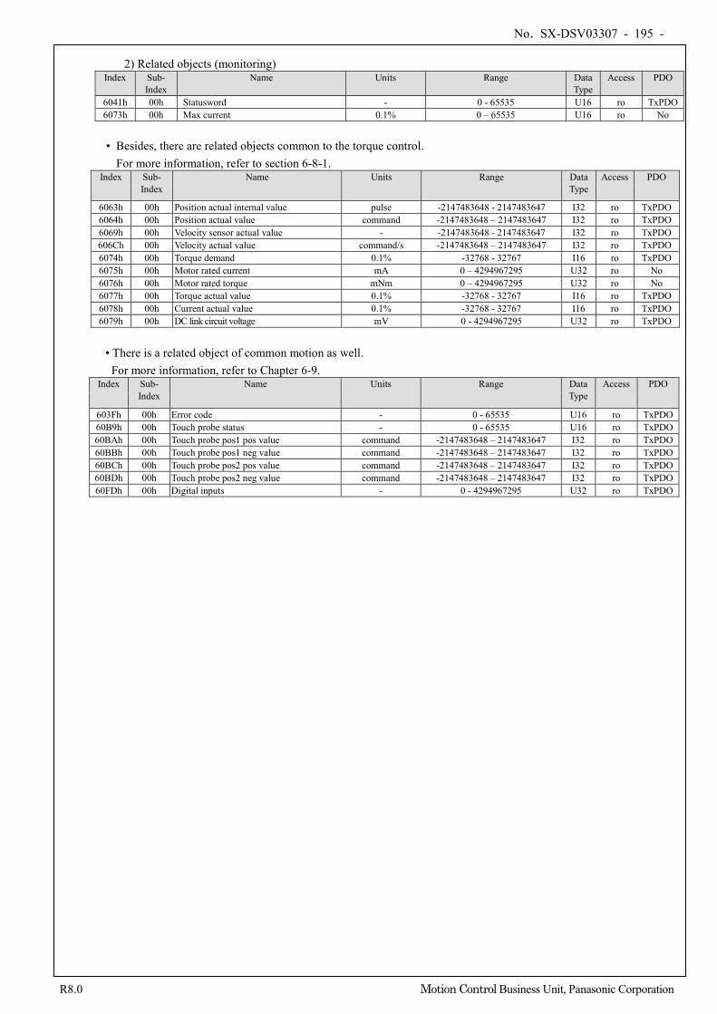
No. SX-DSV03307 - 195 -
R8.0 Motion Control Business Unit, Panasonic Corporation
2) Related objects (monitoring)
Index Sub- Index
Name Units Range Data Type
Access PDO
6041h 00h Statusword - 0 - 65535 U16 ro TxPDO 6073h 00h Max current 0.1% 0 – 65535 U16 ro No
• Besides, there are related objects common to the torque control.
For more information, refer to section 6-8-1. Index Sub-
Index Name Units Range Data
Type Access PDO
6063h 00h Position actual internal value pulse -2147483648 - 2147483647 I32 ro TxPDO 6064h 00h Position actual value command -2147483648 – 2147483647 I32 ro TxPDO 6069h 00h Velocity sensor actual value - -2147483648 - 2147483647 I32 ro TxPDO 606Ch 00h Velocity actual value command/s -2147483648 – 2147483647 I32 ro TxPDO 6074h 00h Torque demand 0.1% -32768 - 32767 I16 ro TxPDO 6075h 00h Motor rated current mA 0 – 4294967295 U32 ro No 6076h 00h Motor rated torque mNm 0 – 4294967295 U32 ro No 6077h 00h Torque actual value 0.1% -32768 - 32767 I16 ro TxPDO 6078h 00h Current actual value 0.1% -32768 - 32767 I16 ro TxPDO 6079h 00h DC link circuit voltage mV 0 - 4294967295 U32 ro TxPDO
• There is a related object of common motion as well. For more information, refer to Chapter 6-9.
Index Sub- Index
Name Units Range Data Type
Access PDO
603Fh 00h Error code - 0 - 65535 U16 ro TxPDO 60B9h 00h Touch probe status - 0 - 65535 U16 ro TxPDO 60BAh 00h Touch probe pos1 pos value command -2147483648 – 2147483647 I32 ro TxPDO 60BBh 00h Touch probe pos1 neg value command -2147483648 – 2147483647 I32 ro TxPDO 60BCh 00h Touch probe pos2 pos value command -2147483648 – 2147483647 I32 ro TxPDO 60BDh 00h Touch probe pos2 neg value command -2147483648 – 2147483647 I32 ro TxPDO 60FDh 00h Digital inputs - 0 - 4294967295 U32 ro TxPDO
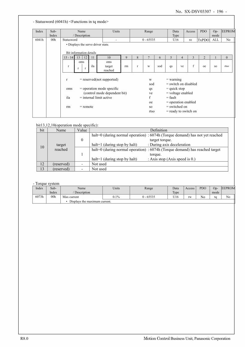
No. SX-DSV03307 - 196 -
R8.0 Motion Control Business Unit, Panasonic Corporation
- Statusword (6041h) <Functions in tq mode>
Index Sub-
Index Name
/ Description Units Range Data
Type Access PDO Op-
mode EEPROM
6041h 00h Statusword - 0 - 65535 U16 ro TxPDO ALL No • Displays the servo driver state. Bit information details
15 - 14 13 12 11 10 9 8 7 6 5 4 3 2 1 0
r oms
ila oms
rm r w sod qs ve f oe so rtso r r target
reached
r = reserved(not supported) w = warning sod = switch on disabled oms = operation mode specific qs = quick stop (control mode dependent bit) ve = voltage enabled ila = internal limit active f = fault oe = operation enabled rm = remote so = switched on
rtso = ready to switch on
bit13,12,10(operation mode specific):
bit Name Value Definition
10 target reached
0 halt=0 (during normal operation) : 6074h (Torque demand) has not yet reached
target torque. halt=1 (during stop by halt) : During axis deceleration
1 halt=0 (during normal operation) : 6074h (Torque demand) has reached target
torque. halt=1 (during stop by halt) : Axis stop (Axis speed is 0.)
12 (reserved) - Not used 13 (reserved) - Not used
- Torque system Index Sub-
Index Name
/ Description Units Range Data
Type Access PDO Op-
mode EEPROM
6073h 00h Max current 0.1% 0 - 65535 U16 rw No tq No • Displays the maximum current.
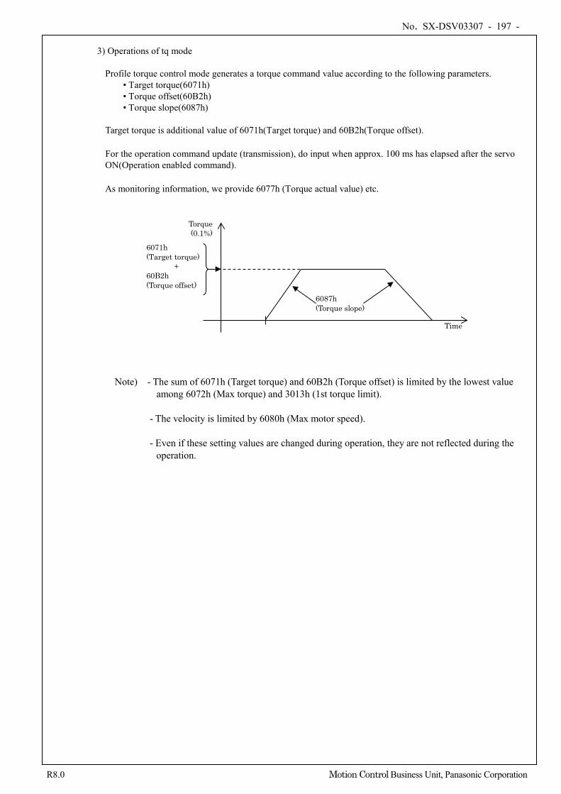
No. SX-DSV03307 - 197 -
R8.0 Motion Control Business Unit, Panasonic Corporation
3) Operations of tq mode
Profile torque control mode generates a torque command value according to the following parameters.
• Target torque(6071h) • Torque offset(60B2h) • Torque slope(6087h)
Target torque is additional value of 6071h(Target torque) and 60B2h(Torque offset).
For the operation command update (transmission), do input when approx. 100 ms has elapsed after the servo ON(Operation enabled command).
As monitoring information, we provide 6077h (Torque actual value) etc.
Note) - The sum of 6071h (Target torque) and 60B2h (Torque offset) is limited by the lowest value
among 6072h (Max torque) and 3013h (1st torque limit).
- The velocity is limited by 6080h (Max motor speed). - Even if these setting values are changed during operation, they are not reflected during the
operation.
Time
Torque (0.1%)
6087h (Torque slope)
6071h (Target torque)
+ 60B2h (Torque offset)
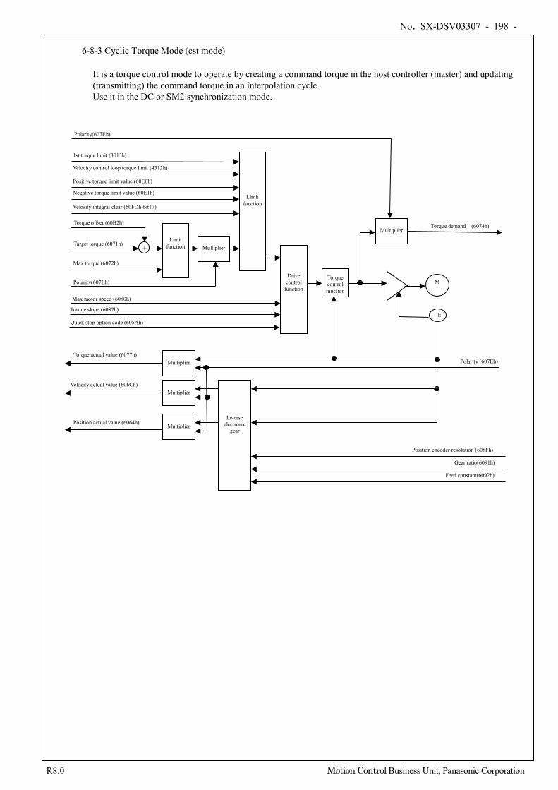
No. SX-DSV03307 - 198 -
R8.0 Motion Control Business Unit, Panasonic Corporation
6-8-3 Cyclic Torque Mode (cst mode)
It is a torque control mode to operate by creating a command torque in the host controller (master) and updating (transmitting) the command torque in an interpolation cycle. Use it in the DC or SM2 synchronization mode.
Drive control function
+
Limit function Multiplier
Polarity(607Eh)
Max motor speed (6080h)
Target torque (6071h)
Torque control
function M
E
Feed constant(6092h)
Gear ratio(6091h)
Position encoder resolution (608Fh)
Position actual value (6064h)
Velocity actual value (606Ch)
Torque actual value (6077h) Polarity (607Eh)
Max torque (6072h)
Torque offset (60B2h)
Multiplier
Multiplier
Multiplier
Inverse electronic
gear
Torque demand (6074h)
Limit function
Multiplier
Polarity(607Eh)
Torque slope (6087h)
Quick stop option code (605Ah)
1st torque limit (3013h) Velocity control loop torque limit (4312h) Positive torque limit value (60E0h) Negative torque limit value (60E1h) Velosity integral clear (60FDh-bit17)
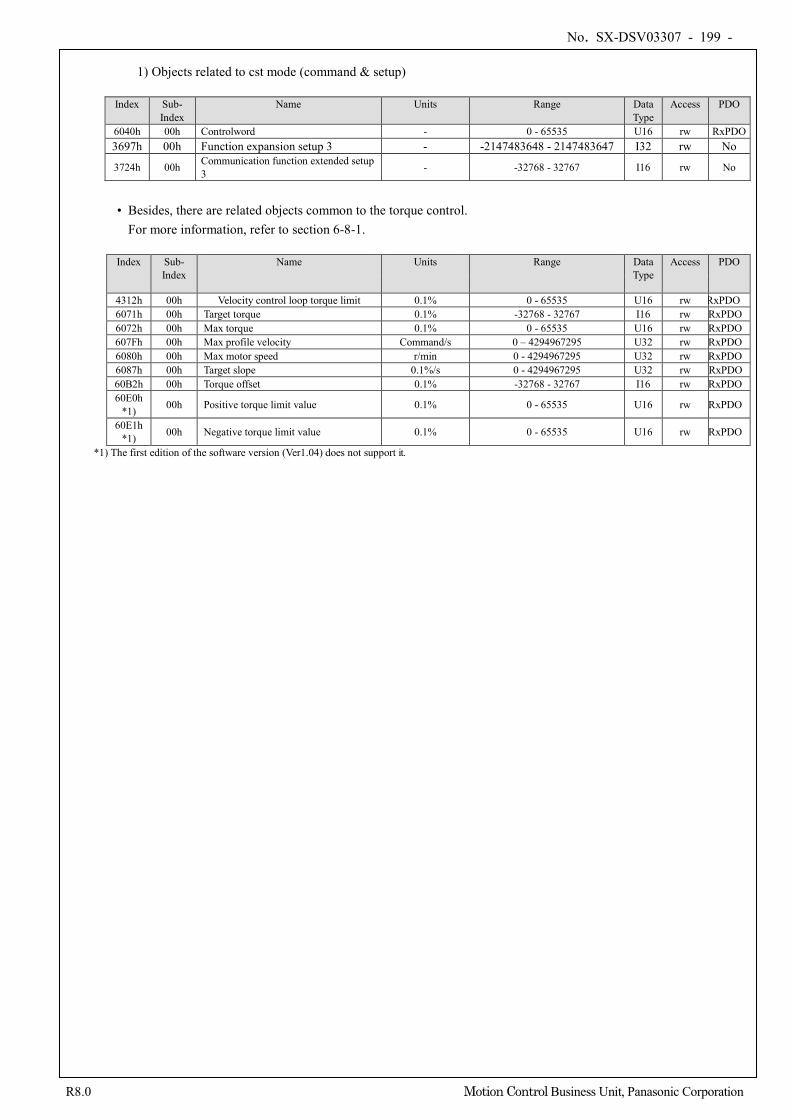
No. SX-DSV03307 - 199 -
R8.0 Motion Control Business Unit, Panasonic Corporation
1) Objects related to cst mode (command & setup)
Index Sub-
Index Name Units Range Data
Type Access PDO
6040h 00h Controlword - 0 - 65535 U16 rw RxPDO 3697h 00h Function expansion setup 3 - -2147483648 - 2147483647 I32 rw No
3724h 00h Communication function extended setup 3 - -32768 - 32767 I16 rw No
• Besides, there are related objects common to the torque control.
For more information, refer to section 6-8-1.
Index Sub- Index
Name Units Range Data Type
Access PDO
4312h 00h Velocity control loop torque limit 0.1% 0 - 65535 U16 rw RxPDO 6071h 00h Target torque 0.1% -32768 - 32767 I16 rw RxPDO 6072h 00h Max torque 0.1% 0 - 65535 U16 rw RxPDO 607Fh 00h Max profile velocity Command/s 0 – 4294967295 U32 rw RxPDO 6080h 00h Max motor speed r/min 0 - 4294967295 U32 rw RxPDO 6087h 00h Target slope 0.1%/s 0 - 4294967295 U32 rw RxPDO 60B2h 00h Torque offset 0.1% -32768 - 32767 I16 rw RxPDO 60E0h
*1) 00h Positive torque limit value 0.1% 0 - 65535 U16 rw RxPDO
60E1h *1) 00h Negative torque limit value 0.1% 0 - 65535 U16 rw RxPDO
*1) The first edition of the software version (Ver1.04) does not support it.
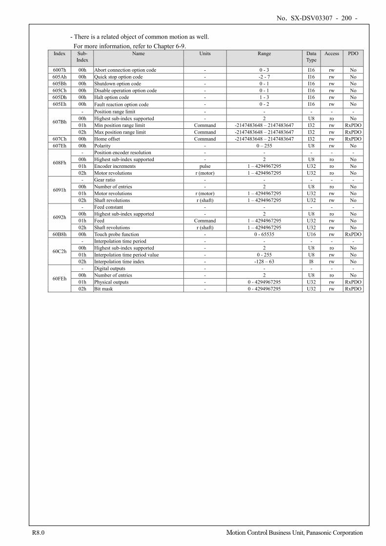
No. SX-DSV03307 - 200 -
R8.0 Motion Control Business Unit, Panasonic Corporation
- There is a related object of common motion as well.
For more information, refer to Chapter 6-9. Index Sub-
Index Name Units Range Data
Type Access PDO
6007h 00h Abort connection option code - 0 - 3 I16 rw No 605Ah 00h Quick stop option code - -2 - 7 I16 rw No 605Bh 00h Shutdown option code - 0 - 1 I16 rw No 605Ch 00h Disable operation option code - 0 - 1 I16 rw No 605Dh 00h Halt option code - 1 - 3 I16 rw No 605Eh 00h Fault reaction option code - 0 - 2 I16 rw No
607Bh
- Position range limit - - - - - 00h Highest sub-index supported - 2 U8 ro No 01h Min position range limit Command -2147483648 – 2147483647 I32 rw RxPDO 02h Max position range limit Command -2147483648 – 2147483647 I32 rw RxPDO
607Ch 00h Home offset Command -2147483648 – 2147483647 I32 rw RxPDO 607Eh 00h Polarity - 0 – 255 U8 rw No
608Fh
- Position encoder resolution - - - - - 00h Highest sub-index supported - 2 U8 ro No 01h Encoder increments pulse 1 – 4294967295 U32 ro No 02h Motor revolutions r (motor) 1 – 4294967295 U32 ro No
6091h
- Gear ratio - - - - - 00h Number of entries - 2 U8 ro No 01h Motor revolutions r (motor) 1 – 4294967295 U32 rw No 02h Shaft revolutions r (shaft) 1 – 4294967295 U32 rw No
6092h
- Feed constant - - - - - 00h Highest sub-index supported - 2 U8 ro No 01h Feed Command 1 – 4294967295 U32 rw No 02h Shaft revolutions r (shaft) 1 – 4294967295 U32 rw No
60B8h 00h Touch probe function - 0 - 65535 U16 rw RxPDO
60C2h
- Interpolation time period - - - - - 00h Highest sub-index supported - 2 U8 ro No 01h Interpolation time period value - 0 - 255 U8 rw No 02h Interpolation time index - -128 – 63 I8 rw No
60FEh
- Digital outputs - - - - - 00h Number of entries - 2 U8 ro No 01h Physical outputs - 0 - 4294967295 U32 rw RxPDO 02h Bit mask - 0 - 4294967295 U32 rw RxPDO
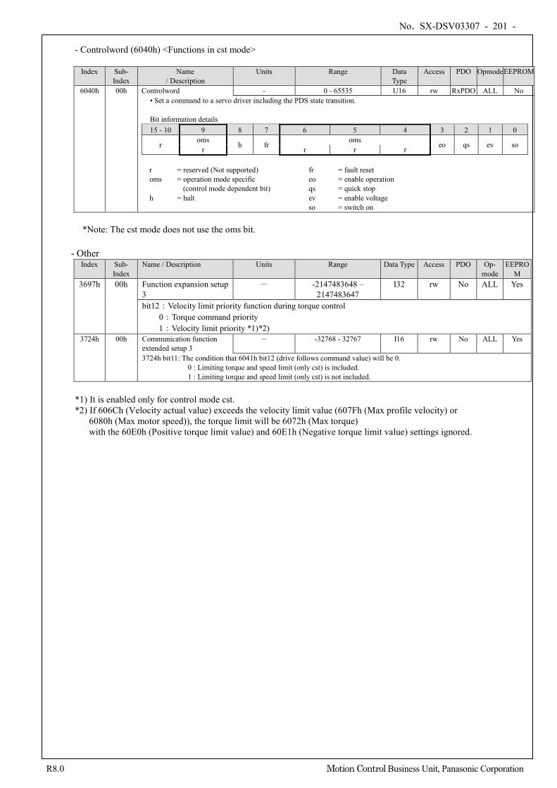
No. SX-DSV03307 - 201 -
R8.0 Motion Control Business Unit, Panasonic Corporation
- Controlword (6040h) <Functions in cst mode>
Index Sub-
Index Name
/ Description Units Range Data
Type Access PDO Opmode EEPROM
6040h 00h Controlword - 0 - 65535 U16 rw RxPDO ALL No • Set a command to a servo driver including the PDS state transition.
Bit information details 15 - 10 9 8 7 6 5 4 3 2 1 0
r oms h fr oms eo qs ev so r r r r
r = reserved (Not supported) fr = fault reset oms = operation mode specific eo = enable operation
(control mode dependent bit) qs = quick stop h = halt ev = enable voltage
so = switch on
*Note: The cst mode does not use the oms bit.
- Other Index Sub-
Index Name / Description Units Range Data Type Access PDO Op-
mode EEPRO
M 3697h 00h Function expansion setup
3 - -2147483648 –
2147483647 I32 rw No ALL Yes
bit12:Velocity limit priority function during torque control 0:Torque command priority
1:Velocity limit priority *1)*2) 3724h 00h Communication function
extended setup 3 - -32768 - 32767 I16 rw No ALL Yes
3724h bit11: The condition that 6041h bit12 (drive follows command value) will be 0. 0 : Limiting torque and speed limit (only cst) is included. 1 : Limiting torque and speed limit (only cst) is not included.
*1) It is enabled only for control mode cst. *2) If 606Ch (Velocity actual value) exceeds the velocity limit value (607Fh (Max profile velocity) or
6080h (Max motor speed)), the torque limit will be 6072h (Max torque) with the 60E0h (Positive torque limit value) and 60E1h (Negative torque limit value) settings ignored.
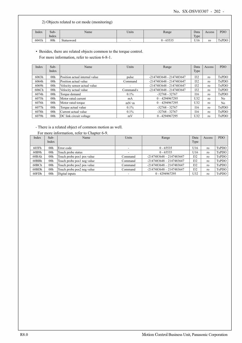
No. SX-DSV03307 - 202 -
R8.0 Motion Control Business Unit, Panasonic Corporation
2) Objects related to cst mode (monitoring)
Index Sub-
Index Name Units Range Data
Type Access PDO
6041h 00h Statusword - 0 - 65535 U16 ro TxPDO
• Besides, there are related objects common to the torque control. For more information, refer to section 6-8-1.
Index Sub-
Index Name Units Range Data
Type Access PDO
6063h 00h Position actual internal value pulse -2147483648 - 2147483647 I32 ro TxPDO 6064h 00h Position actual value Command -2147483648 - 2147483647 I32 ro TxPDO 6069h 00h Velocity sensor actual value - -2147483648 - 2147483647 I32 ro TxPDO 606Ch 00h Velocity actual value Command/s -2147483648 - 2147483647 I32 ro TxPDO 6074h 00h Torque demand 0.1% -32768 - 32767 I16 ro TxPDO 6075h 00h Motor rated current mA 0 – 4294967295 U32 ro No 6076h 00h Motor rated torque mN・m 0 – 4294967295 U32 ro No 6077h 00h Torque actual value 0.1% -32768 - 32767 I16 ro TxPDO 6078h 00h Current actual value 0.1% -32768 - 32767 I16 ro TxPDO 6079h 00h DC link circuit voltage mV 0 - 4294967295 U32 ro TxPDO
- There is a related object of common motion as well.
For more information, refer to Chapter 6-9. Index Sub-
Index Name Units Range Data
Type Access PDO
603Fh 00h Error code - 0 - 65535 U16 ro TxPDO 60B9h 00h Touch probe status - 0 - 65535 U16 ro TxPDO 60BAh 00h Touch probe pos1 pos value Command -2147483648 – 2147483647 I32 ro TxPDO 60BBh 00h Touch probe pos1 neg value Command -2147483648 – 2147483647 I32 ro TxPDO 60BCh 00h Touch probe pos2 pos value Command -2147483648 – 2147483647 I32 ro TxPDO 60BDh 00h Touch probe pos2 neg value Command -2147483648 – 2147483647 I32 ro TxPDO 60FDh 00h Digital inputs - 0 - 4294967295 U32 ro TxPDO
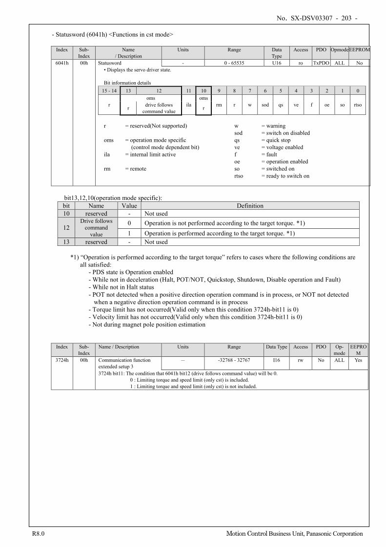
No. SX-DSV03307 - 203 -
R8.0 Motion Control Business Unit, Panasonic Corporation
- Statusword (6041h) <Functions in cst mode>
Index Sub-
Index Name
/ Description Units Range Data
Type Access PDO Opmode EEPROM
6041h 00h Statusword - 0 - 65535 U16 ro TxPDO ALL No • Displays the servo driver state. Bit information details
15 - 14 13 12 11 10 9 8 7 6 5 4 3 2 1 0
r oms
ila oms
rm r w sod qs ve f oe so rtso r drive follows command value r
r = reserved(Not supported) w = warning sod = switch on disabled oms = operation mode specific qs = quick stop (control mode dependent bit) ve = voltage enabled ila = internal limit active f = fault oe = operation enabled rm = remote so = switched on
rtso = ready to switch on
bit13,12,10(operation mode specific): bit Name Value Definition 10 reserved - Not used
12 Drive follows
command value
0 Operation is not performed according to the target torque. *1) 1 Operation is performed according to the target torque. *1)
13 reserved - Not used *1) “Operation is performed according to the target torque” refers to cases where the following conditions are
all satisfied: - PDS state is Operation enabled - While not in deceleration (Halt, POT/NOT, Quickstop, Shutdown, Disable operation and Fault) - While not in Halt status - POT not detected when a positive direction operation command is in process, or NOT not detected
when a negative direction operation command is in process - Torque limit has not occurred(Valid only when this condition 3724h-bit11 is 0) - Velocity limit has not occurred(Valid only when this condition 3724h-bit11 is 0) - Not during magnet pole position estimation
Index Sub-
Index Name / Description Units Range Data Type Access PDO Op-
mode EEPRO
M 3724h 00h Communication function
extended setup 3 - -32768 - 32767 I16 rw No ALL Yes
3724h bit11: The condition that 6041h bit12 (drive follows command value) will be 0. 0 : Limiting torque and speed limit (only cst) is included. 1 : Limiting torque and speed limit (only cst) is not included.
No. SX-DSV03307 - 204 -
R8.0 Motion Control Business Unit, Panasonic Corporation
3) Operations of cst mode
• Motion profile (trajectory) generation is done by the master, not the slave in cyclic torque control mode. • Target torque is additional value of 6071h(Target torque) and 60B2h(Torque offset). • For the operation command update (transmission), do input when approx. 100 ms has elapsed after the servo
ON(Operation enabled command). • 60C2h (Interpolation time period) indicates the cycle to update the two object for 6071h (Target torque) and 60B2h (Torque offset).This value is set to the cycle which is the same as 1C32-02h(Cycle time).
• As monitoring information, we provide 6077h (Torque actual value) etc. Note) - The sum of 6071h (Target torque) and 60B2h (Torque offset) is limited by below EtherCAT object. When 3521h(Selection of torque limit)=5 is set: 60E0h(Positive torque limit value), 60E1h(Negative torque limit value)
When 3521h(Selection of torque limit)≠5 is set: 3013h(1st torque limit)
- The velocity is limited by 6080h (Max motor speed).
No. SX-DSV03307 - 205 -
R8.0 Motion Control Business Unit, Panasonic Corporation
6-9 Common Motion Function
6-9-1 Touch Probe Function (position latch request/release)
This function selects a latch trigger signal from external input (EXT1/EXT2) or Z-phase (Z phase position on incremental scale) and latches the feedback position.
• When it uses a external input (EXT1/EXT2) by the signal of latch trigger, assign EXT1 to SI5 and assign EXT2
to SI6, respectively. When Homing operation is carried out without assigning, Err88.3 (Improper operation error protection) occurs.
• If the latch trigger signal is external input(EXT1/EXT2), the import difference occurs.
Reduce the velocity around the latch trigger signal input as much as possible.
• Set the input ON width and OFF width of the latch trigger signal to 2 ms or more.
• If the Z-phase is selected by the trigger while using absolute scale, Err88.3 (Improper operation error protection) occurs.
• If the setting chooses the Z-phase selection at the trigger, please do not select edge falling. The operation can not be guaranteed if it set to the above setting.
• The touch probe function is disabled in the cases below: (The value of 60B9h is cleared to 0.)
1) The ESM state becomes Init 2) The mode changed into the hm mode
• In the enhanced version 4 or earlier, do not set the rising edge and the falling edge to the same Touch Probe at the same time . The behavior cannot be guaranteed if both are set at the same time. In the enhanced version 5 or later, the rising edge and the falling edge can be set to the same Touch Probe at the same time.
• Multi-turn clear, test run, frequency response analyzing, fit gain, and pin assign setting from PANATERM may
not be performed when TouchProbe is running. Behavior when one of these is performed cannot be guaranteed.
• By setting bit13 of 3697h (Function expansion setup 3) to 1, bit 1/2/9/10 of 60B9h (Touch probe status) is
inverted and output. *1) *1) It is not supported in software versions prior to enhanced version 4.
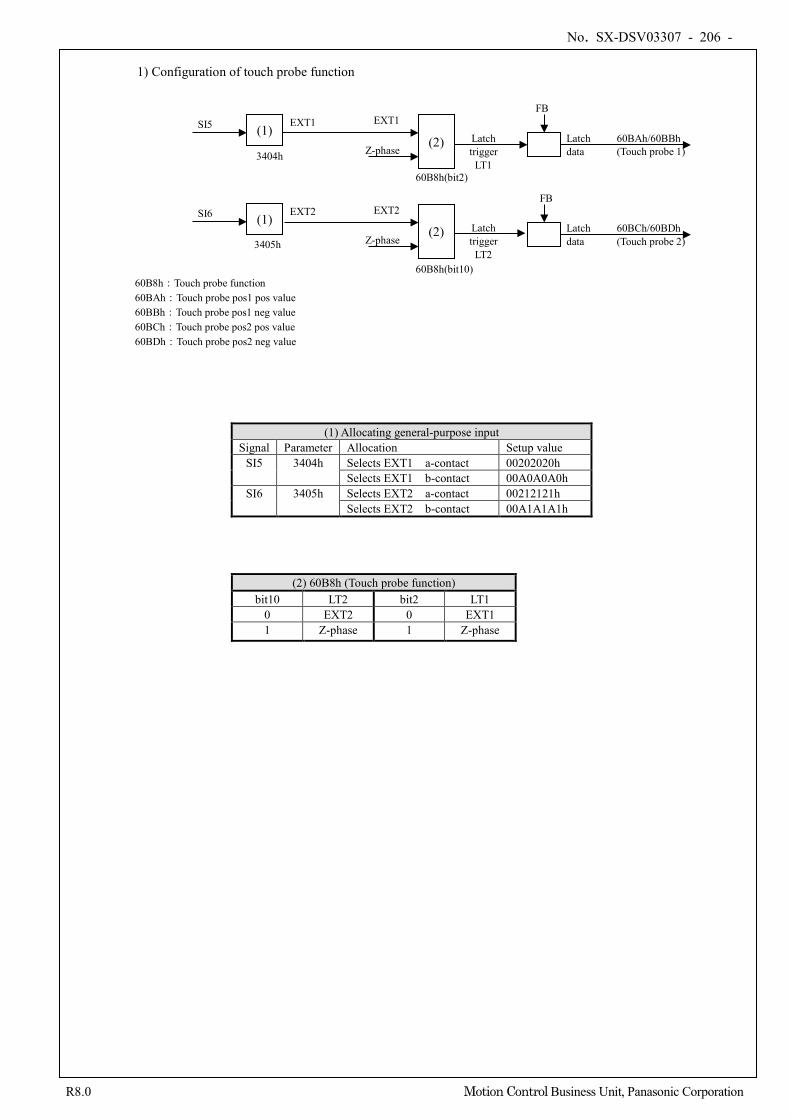
No. SX-DSV03307 - 206 -
R8.0 Motion Control Business Unit, Panasonic Corporation
1) Configuration of touch probe function
(2) 60B8h (Touch probe function) bit10 LT2 bit2 LT1
0 EXT2 0 EXT1 1 Z-phase 1 Z-phase
SI5 EXT1 EXT1
3404h
Latch trigger
LT1
60B8h(bit10)
60B8h(bit2)
Z-phase
EXT2
Latch trigger
LT2
FB
FB
Latch data
60BAh/60BBh (Touch probe 1)
Latch data
60BCh/60BDh (Touch probe 2) Z-phase
(1) (2)
(2)
60B8h:Touch probe function 60BAh:Touch probe pos1 pos value 60BBh:Touch probe pos1 neg value 60BCh:Touch probe pos2 pos value 60BDh:Touch probe pos2 neg value
SI6 (1) EXT2
3405h
(1) Allocating general-purpose input Signal Parameter Allocation Setup value
SI5 3404h Selects EXT1 a-contact 00202020h Selects EXT1 b-contact 00A0A0A0h
SI6 3405h Selects EXT2 a-contact 00212121h Selects EXT2 b-contact 00A1A1A1h
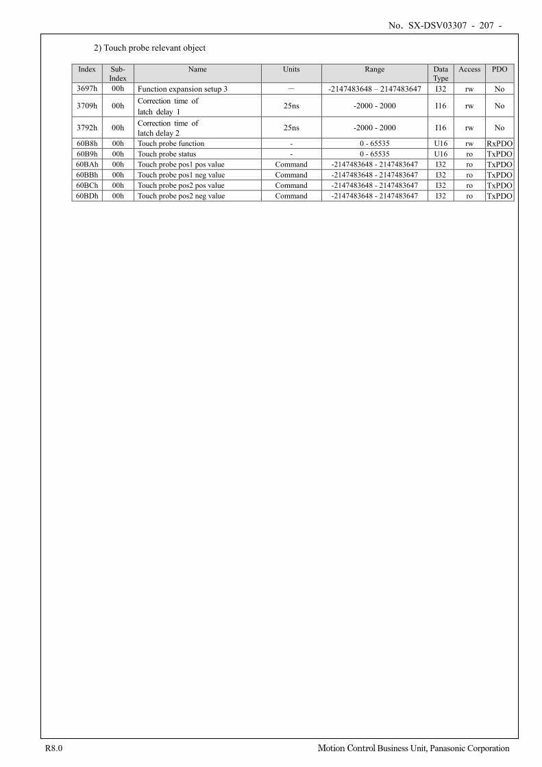
No. SX-DSV03307 - 207 -
R8.0 Motion Control Business Unit, Panasonic Corporation
2) Touch probe relevant object
Index Sub- Index
Name Units Range Data Type
Access PDO
3697h 00h Function expansion setup 3 - -2147483648 – 2147483647 I32 rw No
3709h 00h Correction time of latch delay 1
25ns -2000 - 2000 I16 rw No
3792h 00h Correction time of latch delay 2
25ns -2000 - 2000 I16 rw No
60B8h 00h Touch probe function - 0 - 65535 U16 rw RxPDO 60B9h 00h Touch probe status - 0 - 65535 U16 ro TxPDO 60BAh 00h Touch probe pos1 pos value Command -2147483648 - 2147483647 I32 ro TxPDO 60BBh 00h Touch probe pos1 neg value Command -2147483648 - 2147483647 I32 ro TxPDO 60BCh 00h Touch probe pos2 pos value Command -2147483648 - 2147483647 I32 ro TxPDO 60BDh 00h Touch probe pos2 neg value Command -2147483648 - 2147483647 I32 ro TxPDO
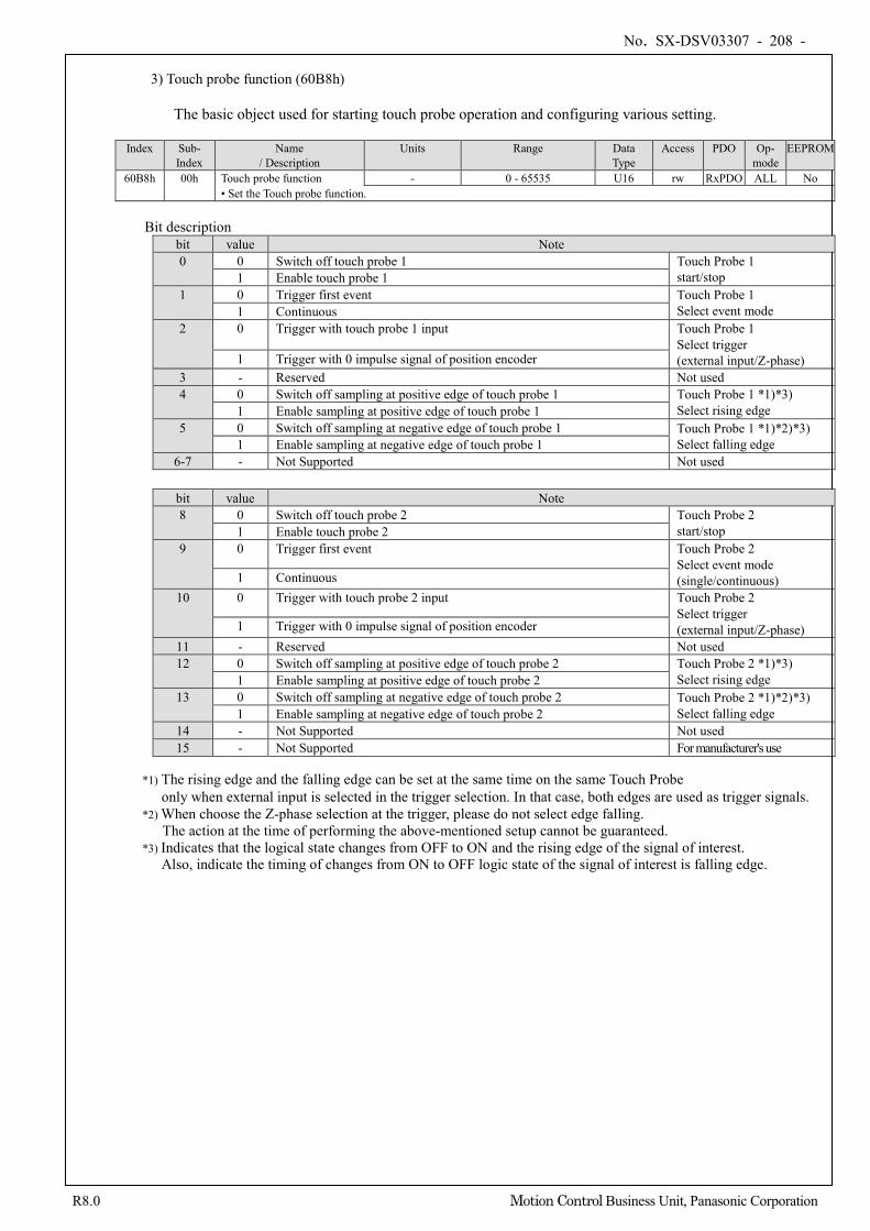
No. SX-DSV03307 - 208 -
R8.0 Motion Control Business Unit, Panasonic Corporation
3) Touch probe function (60B8h)
The basic object used for starting touch probe operation and configuring various setting.
Index Sub-
Index Name
/ Description Units Range Data
Type Access PDO Op-
mode EEPROM
60B8h 00h Touch probe function - 0 - 65535 U16 rw RxPDO ALL No • Set the Touch probe function.
Bit description
bit value Note 0 0 Switch off touch probe 1 Touch Probe 1
start/stop 1 Enable touch probe 1 1 0 Trigger first event Touch Probe 1
Select event mode 1 Continuous 2 0 Trigger with touch probe 1 input Touch Probe 1
Select trigger (external input/Z-phase) 1 Trigger with 0 impulse signal of position encoder
3 - Reserved Not used 4 0 Switch off sampling at positive edge of touch probe 1 Touch Probe 1 *1)*3)
Select rising edge 1 Enable sampling at positive edge of touch probe 1 5 0 Switch off sampling at negative edge of touch probe 1 Touch Probe 1 *1)*2)*3)
Select falling edge 1 Enable sampling at negative edge of touch probe 1 6-7 - Not Supported Not used
bit value Note 8 0 Switch off touch probe 2 Touch Probe 2
start/stop 1 Enable touch probe 2 9 0 Trigger first event Touch Probe 2
Select event mode (single/continuous) 1 Continuous
10 0 Trigger with touch probe 2 input Touch Probe 2 Select trigger (external input/Z-phase) 1 Trigger with 0 impulse signal of position encoder
11 - Reserved Not used 12 0 Switch off sampling at positive edge of touch probe 2 Touch Probe 2 *1)*3)
Select rising edge 1 Enable sampling at positive edge of touch probe 2 13 0 Switch off sampling at negative edge of touch probe 2 Touch Probe 2 *1)*2)*3)
Select falling edge 1 Enable sampling at negative edge of touch probe 2 14 - Not Supported Not used 15 - Not Supported For manufacturer's use
*1) The rising edge and the falling edge can be set at the same time on the same Touch Probe
only when external input is selected in the trigger selection. In that case, both edges are used as trigger signals. *2) When choose the Z-phase selection at the trigger, please do not select edge falling.
The action at the time of performing the above-mentioned setup cannot be guaranteed. *3) Indicates that the logical state changes from OFF to ON and the rising edge of the signal of interest.
Also, indicate the timing of changes from ON to OFF logic state of the signal of interest is falling edge.
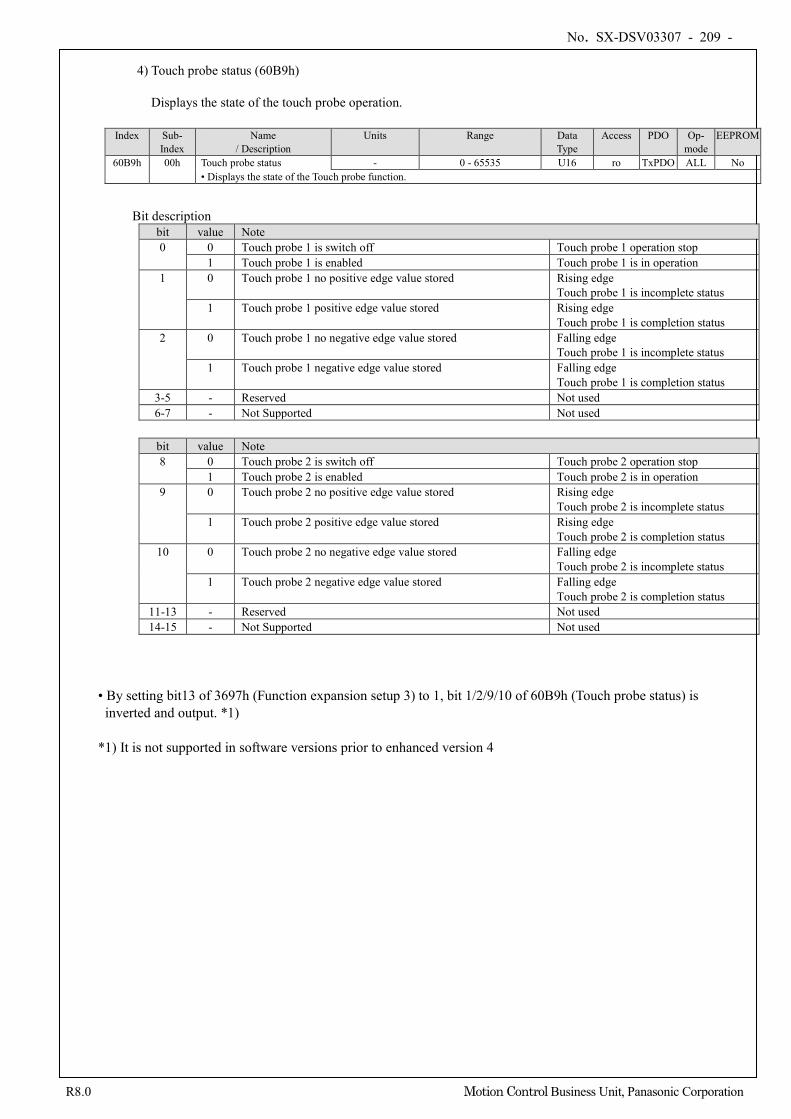
No. SX-DSV03307 - 209 -
R8.0 Motion Control Business Unit, Panasonic Corporation
4) Touch probe status (60B9h)
Displays the state of the touch probe operation.
Index Sub-
Index Name
/ Description Units Range Data
Type Access PDO Op-
mode EEPROM
60B9h 00h Touch probe status - 0 - 65535 U16 ro TxPDO ALL No • Displays the state of the Touch probe function.
Bit description
bit value Note 0 0 Touch probe 1 is switch off Touch probe 1 operation stop
1 Touch probe 1 is enabled Touch probe 1 is in operation 1 0 Touch probe 1 no positive edge value stored Rising edge
Touch probe 1 is incomplete status 1 Touch probe 1 positive edge value stored Rising edge
Touch probe 1 is completion status 2 0 Touch probe 1 no negative edge value stored Falling edge
Touch probe 1 is incomplete status 1 Touch probe 1 negative edge value stored Falling edge
Touch probe 1 is completion status 3-5 - Reserved Not used 6-7 - Not Supported Not used
bit value Note 8 0 Touch probe 2 is switch off Touch probe 2 operation stop
1 Touch probe 2 is enabled Touch probe 2 is in operation 9 0 Touch probe 2 no positive edge value stored Rising edge
Touch probe 2 is incomplete status 1 Touch probe 2 positive edge value stored Rising edge
Touch probe 2 is completion status 10 0 Touch probe 2 no negative edge value stored Falling edge
Touch probe 2 is incomplete status 1 Touch probe 2 negative edge value stored Falling edge
Touch probe 2 is completion status 11-13 - Reserved Not used 14-15 - Not Supported Not used
• By setting bit13 of 3697h (Function expansion setup 3) to 1, bit 1/2/9/10 of 60B9h (Touch probe status) is inverted and output. *1)
*1) It is not supported in software versions prior to enhanced version 4
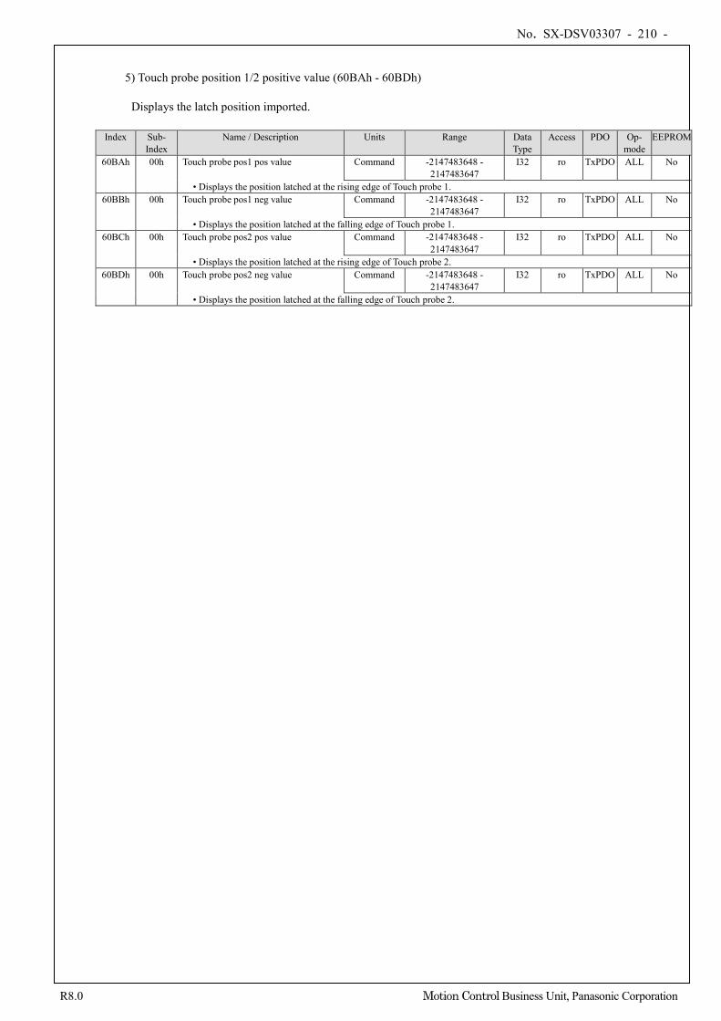
No. SX-DSV03307 - 210 -
R8.0 Motion Control Business Unit, Panasonic Corporation
5) Touch probe position 1/2 positive value (60BAh - 60BDh)
Displays the latch position imported. Index Sub-
Index Name / Description Units Range Data
Type Access PDO Op-
mode EEPROM
60BAh 00h Touch probe pos1 pos value Command -2147483648 - 2147483647
I32 ro TxPDO ALL No
• Displays the position latched at the rising edge of Touch probe 1. 60BBh 00h Touch probe pos1 neg value Command -2147483648 -
2147483647 I32 ro TxPDO ALL No
• Displays the position latched at the falling edge of Touch probe 1. 60BCh 00h Touch probe pos2 pos value Command -2147483648 -
2147483647 I32 ro TxPDO ALL No
• Displays the position latched at the rising edge of Touch probe 2. 60BDh 00h Touch probe pos2 neg value Command -2147483648 -
2147483647 I32 ro TxPDO ALL No
• Displays the position latched at the falling edge of Touch probe 2.
No. SX-DSV03307 - 211 -
R8.0 Motion Control Business Unit, Panasonic Corporation
6) Starting touch probe operation
When the bit0/bit8 (Touch probe start/stop) of 60B8h(Touch probe function) is changed from 0 (Stop) to 1 (Start), imports various setting conditions (60B8h: bits 1 - 7/bits 9 - 15) and starts the Touch probe operation. To enable the change of various setting conditions, put back the bit0/bit8 to 0 (Stop) once and then set the bit0/bit8 to 1 (Start) again.
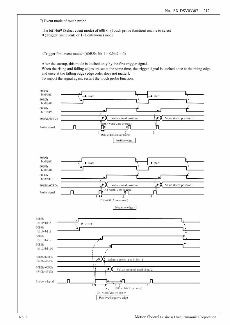
No. SX-DSV03307 - 212 -
R8.0 Motion Control Business Unit, Panasonic Corporation
7) Event mode of touch probe
The bit1/bit9 (Select event mode) of 60B8h (Touch probe function) enable to select 0 (Trigger first event) or 1 (Continuous) mode.
<Trigger first event mode> (60B8h: bit 1 = 0/bit9 = 0) After the startup, this mode is latched only by the first trigger signal. When the rising and falling edges are set at the same time, the trigger signal is latched once at the rising edge and once at the falling edge (edge order does not matter). To import the signal again, restart the touch probe function.
60B8h bit0/bit8 60B9h bit0/bit8 60B9h bit1/bit9
60BAh/60BCh
Probe signal
1 2 3
Value stored position 1 Value stored position 3
start start
Positive edge:
60B8h bit0/bit8 60B9h bit0/bit8 60B9h bit2/bit10
60BBh/60BDh
Probe signal 2 3
Value stored position 1 Value stored position 3
start start
Negative edge:
1
(OFF width: 2 ms or more)
(ON width: 2 ms or more)
60B8h
bit0/bit8
60B9h
bit0/bit8
60B9h
Bit1/bit9
60BAh/60BCh
4F4Bh/4F4Dh
Probe signal
2 3
Value stored position 1
start
Positive/Negative edge
1
(ON width 2ms or more)
(OFF width 2 or more)
60B9h
bit2/bit10
Value stored position 2 60BBh/60BDh
4F4Ch/4F4Eh
(OFF width: 2 ms or more)
(ON width: 2 ms or more)
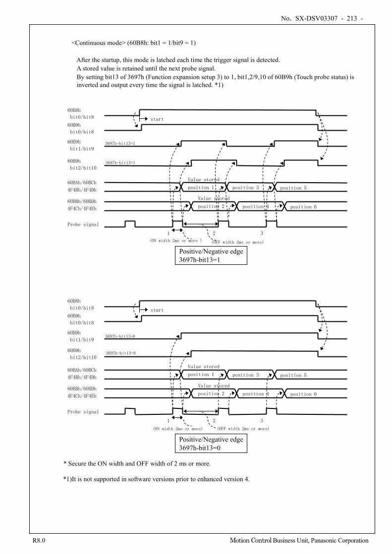
No. SX-DSV03307 - 213 -
R8.0 Motion Control Business Unit, Panasonic Corporation
<Continuous mode> (60B8h: bit1 = 1/bit9 = 1) After the startup, this mode is latched each time the trigger signal is detected.
A stored value is retained until the next probe signal. By setting bit13 of 3697h (Function expansion setup 3) to 1, bit1,2/9,10 of 60B9h (Touch probe status) is inverted and output every time the signal is latched. *1)
* Secure the ON width and OFF width of 2 ms or more.
*1)It is not supported in software versions prior to enhanced version 4.
(OFF width 2ms or more)
60B8h
bit0/bit8
60B9h
bit0/bit8
60B9h
bit1/bit9
60BAh/60BCh
4F4Bh/4F4Dh
Probe signal
1 2 3
Value stored
position 1 position 5
start
position 3
Positive/Negative edge 3697h-bit13=1
(ON width 2ms or more )
3697h-bit13=1
60B9h
bit2/bit10
60BBh/60BDh
4F4Ch/4F4Eh
Value stored
position 2 position 6 position 4
3697h-bit13=1
(OFF width 2ms or more)
60B8h
bit0/bit8
60B9h
bit0/bit8
60B9h
bit1/bit9
60BAh/60BCh
4F4Bh/4F4Dh
Probe signal
1 2 3
Value stored
position 1 position 5
start
position 3
Positive/Negative edge 3697h-bit13=0
(ON width 2ms or more)
3697h-bit13=0
60B9h
bit2/bit10
60BBh/60BDh
4F4Ch/4F4Eh
Value stored
position 2 position 6 position 4
3697h-bit13=0
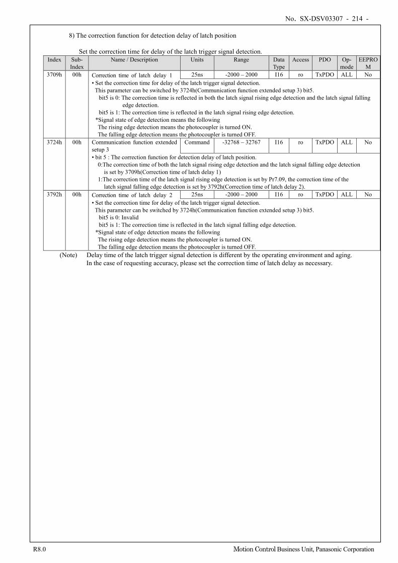
No. SX-DSV03307 - 214 -
R8.0 Motion Control Business Unit, Panasonic Corporation
8) The correction function for detection delay of latch position
Set the correction time for delay of the latch trigger signal detection.
Index Sub- Index
Name / Description Units Range Data Type
Access PDO Op- mode
EEPROM
3709h 00h Correction time of latch delay 1 25ns -2000 – 2000 I16 ro TxPDO ALL No • Set the correction time for delay of the latch trigger signal detection.
This parameter can be switched by 3724h(Communication function extended setup 3) bit5. bit5 is 0: The correction time is reflected in both the latch signal rising edge detection and the latch signal falling
edge detection. bit5 is 1: The correction time is reflected in the latch signal rising edge detection.
*Signal state of edge detection means the following The rising edge detection means the photocoupler is turned ON. The falling edge detection means the photocoupler is turned OFF.
3724h 00h Communication function extended setup 3
Command -32768 – 32767 I16 ro TxPDO ALL No
• bit 5 : The correction function for detection delay of latch position. 0:The correction time of both the latch signal rising edge detection and the latch signal falling edge detection
is set by 3709h(Correction time of latch delay 1) 1:The correction time of the latch signal rising edge detection is set by Pr7.09, the correction time of the
latch signal falling edge detection is set by 3792h(Correction time of latch delay 2). 3792h 00h Correction time of latch delay 2 25ns -2000 – 2000 I16 ro TxPDO ALL No
• Set the correction time for delay of the latch trigger signal detection. This parameter can be switched by 3724h(Communication function extended setup 3) bit5.
bit5 is 0: Invalid bit5 is 1: The correction time is reflected in the latch signal falling edge detection.
*Signal state of edge detection means the following The rising edge detection means the photocoupler is turned ON. The falling edge detection means the photocoupler is turned OFF.
(Note) Delay time of the latch trigger signal detection is different by the operating environment and aging. In the case of requesting accuracy, please set the correction time of latch delay as necessary.
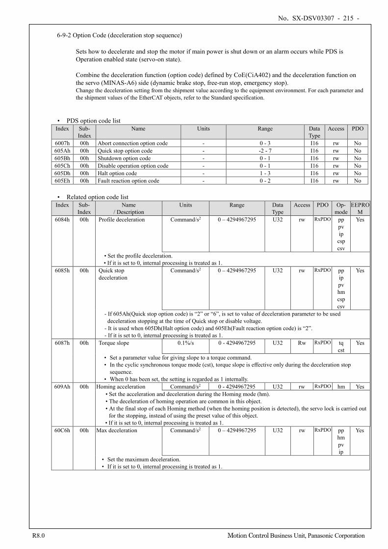
No. SX-DSV03307 - 215 -
R8.0 Motion Control Business Unit, Panasonic Corporation
6-9-2 Option Code (deceleration stop sequence)
Sets how to decelerate and stop the motor if main power is shut down or an alarm occurs while PDS is Operation enabled state (servo-on state). Combine the deceleration function (option code) defined by CoE(CiA402) and the deceleration function on the servo (MINAS-A6) side (dynamic brake stop, free-run stop, emergency stop). Change the deceleration setting from the shipment value according to the equipment environment. For each parameter and the shipment values of the EtherCAT objects, refer to the Standard specification.
• PDS option code list Index Sub-
Index Name Units Range Data
Type Access PDO
6007h 00h Abort connection option code - 0 - 3 I16 rw No 605Ah 00h Quick stop option code - -2 - 7 I16 rw No 605Bh 00h Shutdown option code - 0 - 1 I16 rw No 605Ch 00h Disable operation option code - 0 - 1 I16 rw No 605Dh 00h Halt option code - 1 - 3 I16 rw No 605Eh 00h Fault reaction option code - 0 - 2 I16 rw No
• Related option code list
Index Sub- Index
Name / Description
Units Range Data Type
Access PDO Op- mode
EEPROM
6084h 00h Profile deceleration Command/s2 0 – 4294967295 U32 rw RxPDO pp pv ip
csp csv
Yes
• Set the profile deceleration. • If it is set to 0, internal processing is treated as 1.
6085h 00h Quick stop deceleration
Command/s2 0 – 4294967295 U32 rw RxPDO pp ip pv hm csp csv
Yes
- If 605Ah(Quick stop option code) is “2” or “6”, is set to value of deceleration parameter to be used deceleration stopping at the time of Quick stop or disable voltage.
- It is used when 605Dh(Halt option code) and 605Eh(Fault reaction option code) is “2”. - If it is set to 0, internal processing is treated as 1.
6087h 00h Torque slope 0.1%/s 0 - 4294967295 U32 Rw RxPDO tq cst
Yes
• Set a parameter value for giving slope to a torque command. • In the cyclic synchronous torque mode (cst), torque slope is effective only during the deceleration stop
sequence. • When 0 has been set, the setting is regarded as 1 internally.
609Ah 00h Homing acceleration Command/s2 0 - 4294967295 U32 rw RxPDO hm Yes • Set the acceleration and deceleration during the Homing mode (hm). • The deceleration of homing operation are common in this object. • At the final stop of each Homing method (when the homing position is detected), the servo lock is carried out
for the stopping, instead of using the preset value of this object. • If it is set to 0, internal processing is treated as 1.
60C6h 00h Max deceleration Command/s2 0 – 4294967295 U32 rw RxPDO pp hm pv ip
Yes
• Set the maximum deceleration. • If it is set to 0, internal processing is treated as 1.
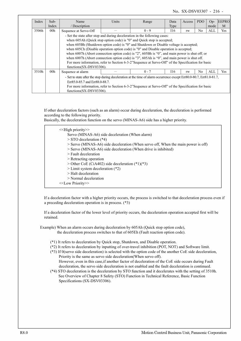
No. SX-DSV03307 - 216 -
R8.0 Motion Control Business Unit, Panasonic Corporation
Index Sub-
Index Name
/ Description Units Range Data
Type Access PDO Op-
mode EEPRO
M 3506h 00h Sequence at Servo-Off - 0 - 9 I16 rw No ALL Yes
- Set the state after stop and during deceleration in the following cases: when 605Ah (Quick stop option code) is "0" and Quick stop is accepted; when 605Bh (Shutdown option code) is "0" and Shutdown or Disable voltage is accepted; when 605Ch (Disable operation option code) is "0" and Disable operation is accepted; when 6007h (Abort connection option code) is "2", 605Bh is “0”, and main power is shut off; or when 6007h (Abort connection option code) is "3", 605Ah is “0”, and main power is shut off.
For more information, refer to Section 6-3-2”Sequence at Servo-Off” of the Specification for basic functions(SX-DSV03306).
3510h 00h Sequence at alarm - 0 - 7 I16 rw No ALL Yes - Set to state after the stop during deceleration at the time of alarm occurrence except Err80.0-80.7, Err81.0-81.7,
Err85.0-85.7 and Err88.0-88.7. For more information, refer to Section 6-3-2”Sequence at Servo-Off” of the Specification for basic functions(SX-DSV03306).
If other deceleration factors (such as an alarm) occur during deceleration, the deceleration is performed according to the following priority. Basically, the deceleration function on the servo (MINAS-A6) side has a higher priority.
<<High priority>> Servo (MINAS-A6) side deceleration (When alarm) > STO deceleration (*4) > Servo (MINAS-A6) side deceleration (When servo off, When the main power is off) > Servo (MINAS-A6) side deceleration (When drive is inhibited) > Fault deceleration > Retracting operation > Other CoE (CiA402) side deceleration (*1)(*3) > Limit system deceleration (*2) > Halt deceleration > Normal deceleration
<<Low Priority>> If a deceleration factor with a higher priority occurs, the process is switched to that deceleration process even if a preceding deceleration operation is in process. (*3) If a deceleration factor of the lower level of priority occurs, the deceleration operation accepted first will be retained.
Example) When an alarm occurs during deceleration by 605Ah (Quick stop option code),
the deceleration process switches to that of 605Eh (Fault reaction option code).
(*1) It refers to deceleration by Quick stop, Shutdown, and Disable operation. (*2) It refers to deceleration by inputting of over-travel inhibition (POT, NOT) and Software limit. (*3) If 0(servo side deceleration) is selected with the option code of the another CoE side deceleration,
Priority is the same as servo side deceleration(When servo off). However, even in this case,if another factor of deceleration of the CoE side occurs during Fault deceleration, the servo side deceleration is not enabled and the fault deceleration is continued.
(*4) STO deceleration is the deceleration by STO function and it decelerates with the setting of 3510h. See Overview of Chapter 8 Safety (STO) Function in Technical Reference, Basic Function
Specifications (SX-DSV03306).
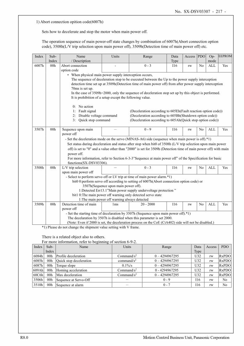
No. SX-DSV03307 - 217 -
R8.0 Motion Control Business Unit, Panasonic Corporation
1) Abort connection opition code(6007h)
Sets how to decelerate and stop the motor when main power off. The operation sequence of main power-off state changes by combination of 6007h(Abort connection option code), 3508h(L/V trip selection upon main power off), 3509h(Detection time of main power off) etc.
Index Sub- Index
Name / Description
Units Range Data Type
Access PDO Op- mode
EEPROM
6007h 00h Abort connection option code
- 0 - 3 I16 rw No ALL Yes
• When physical main power supply interception occurs, The sequence of deceleration stop to be executed between the Up to the power supply interception detection time set up at 3509h(Detection time of main power off) from after power supply interception 70ms is set up. In the case of 3509h=2000, only the sequence of deceleration stop set up by this object is performed. It is prohibition of a setup except the following value.
0: No action 1: Fault signal (Deceleration according to 605Eh(Fault reaction option code)) 2: Disable voltage command (Deceleration according to 605Bh(Shutdown option code)) 3: Quick stop command (Deceleration according to 605Ah(Quick stop option code))
3507h 00h Sequence upon main
power off - 0 - 9 I16 rw No ALL Yes
- Set the deceleration mode on the servo (MINAS-A6) side (sequence when main power is off).*1) Set status during deceleration and status after stop when bit0 of 3508h (L/V trip selection upon main power off) is set to "0" and a value other than "2000" is set for 3509h (Detection time of main power off) with main power off. For more information, refer to Section 6-3-3”Sequence at main power off” of the Specification for basic functions(SX-DSV03306).
3508h 00h L/V trip selection upon main power off
- 0 - 3 I16 rw No ALL Yes
- Select to perform servo off or LV trip at time of main power alarm.*1) bit0 0:perform servo off according to setting of 6007h(Abort connection option code) or
3507h(Sequence upon main power off). 1:Detected Err13.1”Main power supply undervoltage protection ”
bit1 0:The main power off warning only detected servo state 1:The main power off warning always detected
3509h 00h Detection time of main power off
1ms 20 - 2000 I16 rw No ALL Yes
- Set the starting time of decelaration by 3507h (Sequence upon main power off).*1) The decelaration by 3507h is disabled when this parameter is set 2000. (Note: Even if 2000 is set, the deceleration process on the CoE (CiA402) side will not be disabled.)
*1) Please do not change the shipment value setting with V frame. There is a related object also to others. For more information, refer to beginning of section 6-9-2.
Index Sub- Index
Name Units Range Data Type
Access PDO
6084h 00h Profile deceleration Command/s2 0 – 4294967295 U32 rw RxPDO 6085h 00h Quick stop deceleration command/s2 0 – 4294967295 U32 rw RxPDO 6087h 00h Torque slope 0.1%/s 0 – 4294967295 U32 rw RxPDO 609Ah 00h Homing acceleration Command/s2 0 - 4294967295 U32 rw RxPDO 60C6h 00h Max deceleration Command/s2 0 – 4294967295 U32 rw RxPDO 3506h 00h Sequence at Servo-Off - 0 - 9 I16 rw No 3510h 00h Sequence at alarm - 0 - 7 I16 rw No
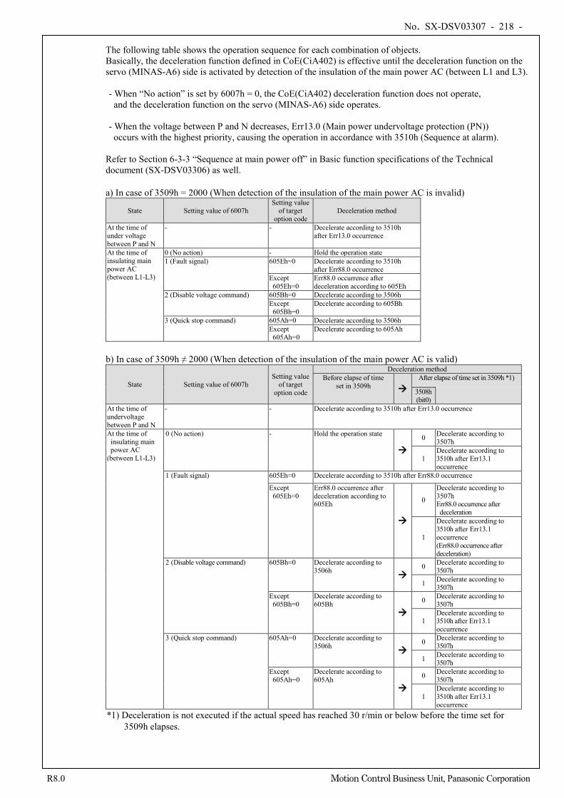
No. SX-DSV03307 - 218 -
R8.0 Motion Control Business Unit, Panasonic Corporation
The following table shows the operation sequence for each combination of objects. Basically, the deceleration function defined in CoE(CiA402) is effective until the deceleration function on the servo (MINAS-A6) side is activated by detection of the insulation of the main power AC (between L1 and L3). - When “No action” is set by 6007h = 0, the CoE(CiA402) deceleration function does not operate,
and the deceleration function on the servo (MINAS-A6) side operates. - When the voltage between P and N decreases, Err13.0 (Main power undervoltage protection (PN))
occurs with the highest priority, causing the operation in accordance with 3510h (Sequence at alarm).
Refer to Section 6-3-3 “Sequence at main power off” in Basic function specifications of the Technical document (SX-DSV03306) as well.
a) In case of 3509h = 2000 (When detection of the insulation of the main power AC is invalid)
State Setting value of 6007h Setting value
of target option code
Deceleration method
At the time of under voltage between P and N
- - Decelerate according to 3510h after Err13.0 occurrence
At the time of insulating main power AC (between L1-L3)
0 (No action) - Hold the operation state 1 (Fault signal) 605Eh=0 Decelerate according to 3510h
after Err88.0 occurrence Except 605Eh=0
Err88.0 occurrence after deceleration according to 605Eh
2 (Disable voltage command) 605Bh=0 Decelerate according to 3506h Except 605Bh=0
Decelerate according to 605Bh
3 (Quick stop command) 605Ah=0 Decelerate according to 3506h Except 605Ah=0
Decelerate according to 605Ah
b) In case of 3509h ≠ 2000 (When detection of the insulation of the main power AC is valid)
State Setting value of 6007h Setting value
of target option code
Deceleration method Before elapse of time
set in 3509h After elapse of time set in 3509h *1)
3508h (bit0)
At the time of undervoltage between P and N
- - Decelerate according to 3510h after Err13.0 occurrence
At the time of insulating main power AC
(between L1-L3)
0 (No action) - Hold the operation state
0 Decelerate according to 3507h
1 Decelerate according to 3510h after Err13.1 occurrence
1 (Fault signal) 605Eh=0 Decelerate according to 3510h after Err88.0 occurrence
Except 605Eh=0
Err88.0 occurrence after deceleration according to 605Eh
0
Decelerate according to 3507h Err88.0 occurrence after deceleration
1
Decelerate according to 3510h after Err13.1 occurrence (Err88.0 occurrence after deceleration)
2 (Disable voltage command) 605Bh=0 Decelerate according to 3506h
0 Decelerate according to 3507h
1 Decelerate according to 3507h
Except 605Bh=0
Decelerate according to 605Bh
0 Decelerate according to 3507h
1 Decelerate according to 3510h after Err13.1 occurrence
3 (Quick stop command) 605Ah=0 Decelerate according to 3506h
0 Decelerate according to 3507h
1 Decelerate according to 3507h
Except 605Ah=0
Decelerate according to 605Ah
0 Decelerate according to 3507h
1 Decelerate according to 3510h after Err13.1 occurrence
*1) Deceleration is not executed if the actual speed has reached 30 r/min or below before the time set for 3509h elapses.
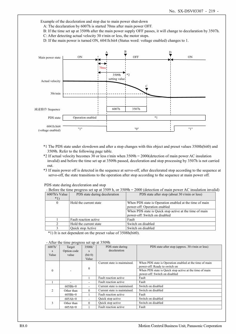
No. SX-DSV03307 - 219 -
R8.0 Motion Control Business Unit, Panasonic Corporation
Example of the deceleration and stop due to main power shut-down
A: The decelaration by 6007h is started 70ms after main power OFF. B: If the time set up at 3509h after the main power supply OFF passes, it will change to decelaration by 3507h. C: After detecting actual velocity 30 r/min or less, the motor stops. D: If the main power is turned ON, 6041h:bit4 (Status word: voltage enabled) changes to 1.
*1 The PDS state under slowdown and after a stop changes with this object and preset values 3508h(bit0) and 3509h. Refer to the following page table.
*2 If actual velocity becomes 30 or less r/min when 3509h = 2000(detection of main power AC insulation invalid) and before the time set up at 3509h passed, deceleration and stop processing by 3507h is not carried out.
*3 If main power off is detected in the sequence at servo-off, after decelerated stop according to the sequence at servo-off, the state transitions to the operation after stop according to the sequence at main power off.
PDS state during deceleration and stop - Before the time progress set up at 3509 h, or 3509h = 2000 (detection of main power AC insulation invalid)
6007h's Value *1)
PDS state during deceleration PDS state after stop (about 30 r/min or less)
0 Hold the current state When PDS state is Operation enabled at the time of main power-off: Operation enabled When PDS state is Quick stop active at the time of main power-off: Switch on disabled
1 Fault reaction active Fault 2 Hold the current state Switch on disabled 3 Quick stop Active Switch on disabled
*1) It is not dependent on the preset value of 3508h(bit0). - After the time progress set up at 3509h
6007h’s
Value
Target Option code
value
3508h’s
(bit 0) Value
PDS state during deceleration
PDS state after stop (approx. 30 r/min or less)
0 - 0
Current state is maintained. When PDS state is Operation enabled at the time of main power-off: Ready to switch on When PDS state is Quick stop active at the time of main power-off: Switch on disabled
1 Fault reaction active Fault 1 - - Fault reaction active Fault
2 605Bh=0 - Current state is maintained. Switch on disabled
Other than 605Bh=0
0 Current state is maintained. Switch on disabled 1 Fault reaction active Fault
3 605Ah=0 - Quick stop active Switch on disabled Other than 605Ah=0
0 Quick stop active Switch on disabled 1 Fault reaction active Fault
Operation enabled
30r/min
Actual velocity
PDS state
6041h:bit4 (voltage enabled) "0" "1"
ON A
C
OFF
"1"
D ON Main power state
70ms
*1
B
6007h 減速動作 Sequence 3507h
3509h setting value
*2
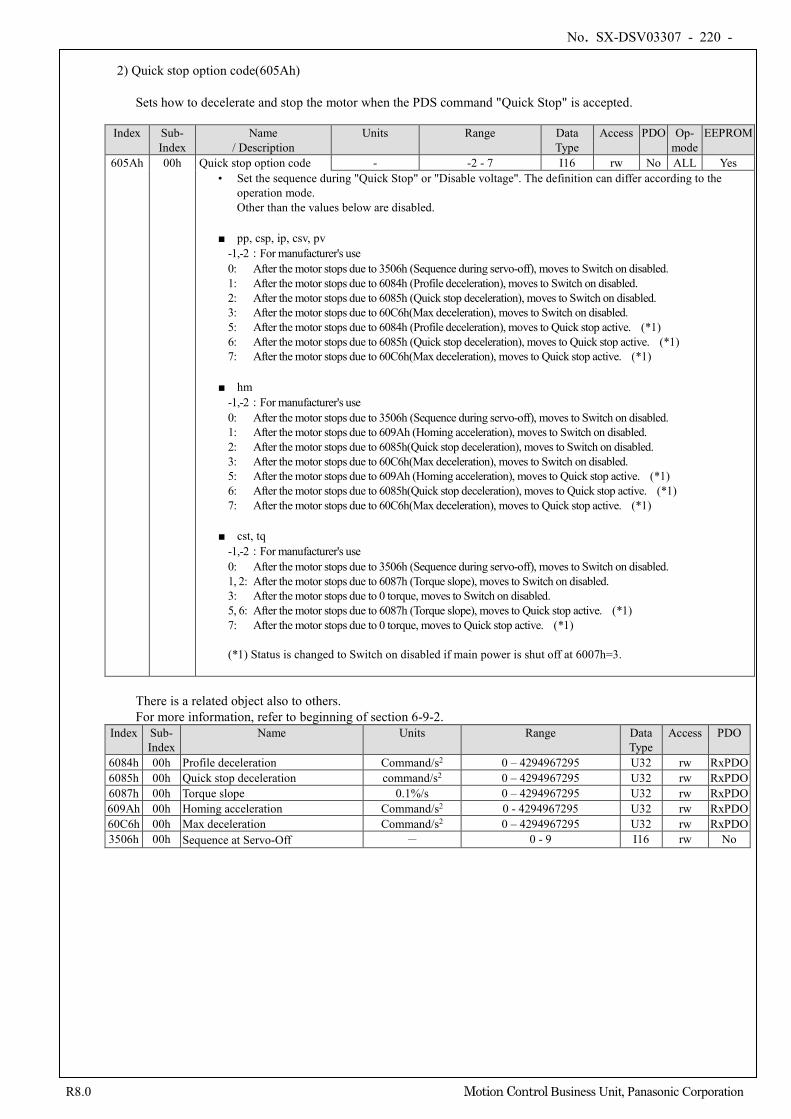
No. SX-DSV03307 - 220 -
R8.0 Motion Control Business Unit, Panasonic Corporation
2) Quick stop option code(605Ah)
Sets how to decelerate and stop the motor when the PDS command "Quick Stop" is accepted.
Index Sub-
Index Name
/ Description Units Range Data
Type Access PDO Op-
mode EEPROM
605Ah 00h Quick stop option code - -2 - 7 I16 rw No ALL Yes • Set the sequence during "Quick Stop" or "Disable voltage". The definition can differ according to the
operation mode. Other than the values below are disabled.
■ pp, csp, ip, csv, pv -1,-2:For manufacturer's use 0: After the motor stops due to 3506h (Sequence during servo-off), moves to Switch on disabled. 1: After the motor stops due to 6084h (Profile deceleration), moves to Switch on disabled. 2: After the motor stops due to 6085h (Quick stop deceleration), moves to Switch on disabled. 3: After the motor stops due to 60C6h(Max deceleration), moves to Switch on disabled. 5: After the motor stops due to 6084h (Profile deceleration), moves to Quick stop active. (*1) 6: After the motor stops due to 6085h (Quick stop deceleration), moves to Quick stop active. (*1) 7: After the motor stops due to 60C6h(Max deceleration), moves to Quick stop active. (*1)
■ hm -1,-2:For manufacturer's use 0: After the motor stops due to 3506h (Sequence during servo-off), moves to Switch on disabled. 1: After the motor stops due to 609Ah (Homing acceleration), moves to Switch on disabled. 2: After the motor stops due to 6085h(Quick stop deceleration), moves to Switch on disabled. 3: After the motor stops due to 60C6h(Max deceleration), moves to Switch on disabled. 5: After the motor stops due to 609Ah (Homing acceleration), moves to Quick stop active. (*1) 6: After the motor stops due to 6085h(Quick stop deceleration), moves to Quick stop active. (*1) 7: After the motor stops due to 60C6h(Max deceleration), moves to Quick stop active. (*1)
■ cst, tq -1,-2:For manufacturer's use 0: After the motor stops due to 3506h (Sequence during servo-off), moves to Switch on disabled. 1, 2: After the motor stops due to 6087h (Torque slope), moves to Switch on disabled. 3: After the motor stops due to 0 torque, moves to Switch on disabled. 5, 6: After the motor stops due to 6087h (Torque slope), moves to Quick stop active. (*1) 7: After the motor stops due to 0 torque, moves to Quick stop active. (*1) (*1) Status is changed to Switch on disabled if main power is shut off at 6007h=3.
There is a related object also to others. For more information, refer to beginning of section 6-9-2.
Index Sub- Index
Name Units Range Data Type
Access PDO
6084h 00h Profile deceleration Command/s2 0 – 4294967295 U32 rw RxPDO 6085h 00h Quick stop deceleration command/s2 0 – 4294967295 U32 rw RxPDO 6087h 00h Torque slope 0.1%/s 0 – 4294967295 U32 rw RxPDO 609Ah 00h Homing acceleration Command/s2 0 - 4294967295 U32 rw RxPDO 60C6h 00h Max deceleration Command/s2 0 – 4294967295 U32 rw RxPDO 3506h 00h Sequence at Servo-Off - 0 - 9 I16 rw No
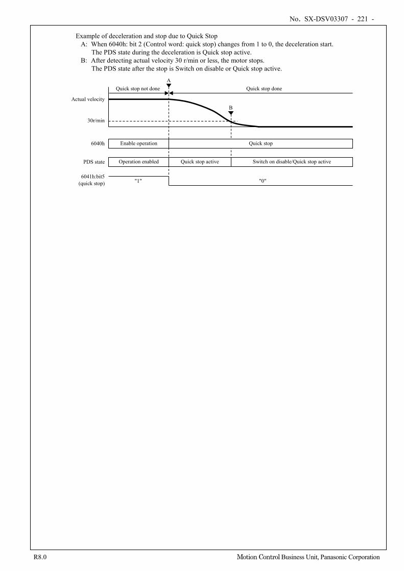
No. SX-DSV03307 - 221 -
R8.0 Motion Control Business Unit, Panasonic Corporation
Example of deceleration and stop due to Quick Stop
A: When 6040h: bit 2 (Control word: quick stop) changes from 1 to 0, the deceleration start. The PDS state during the deceleration is Quick stop active.
B: After detecting actual velocity 30 r/min or less, the motor stops. The PDS state after the stop is Switch on disable or Quick stop active.
Operation enabled Switch on disable/Quick stop active
Enable operation Quick stop 6040h
30r/min
Actual velocity
PDS state
6041h:bit5 (quick stop) "0" "1"
Quick stop not done A
B
Quick stop active
Quick stop done
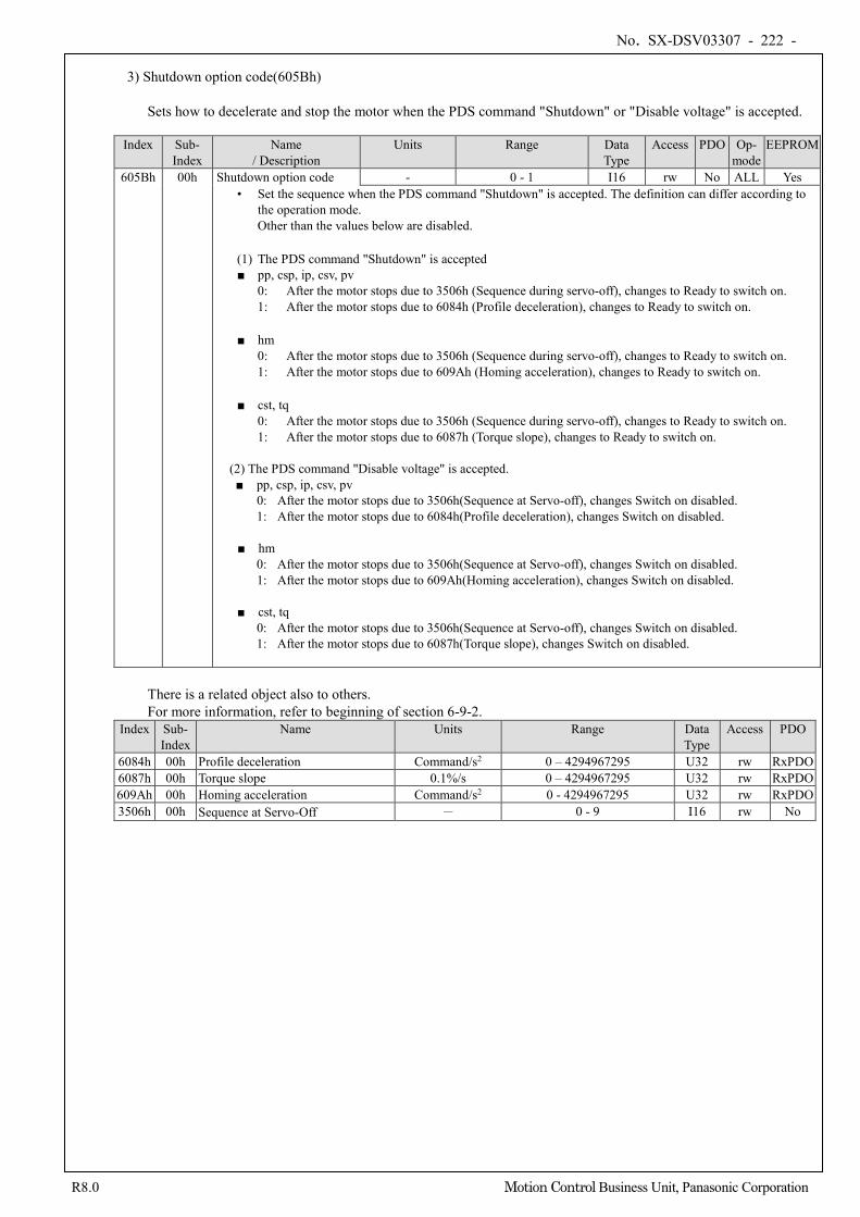
No. SX-DSV03307 - 222 -
R8.0 Motion Control Business Unit, Panasonic Corporation
3) Shutdown option code(605Bh)
Sets how to decelerate and stop the motor when the PDS command "Shutdown" or "Disable voltage" is accepted.
Index Sub- Index
Name / Description
Units Range Data Type
Access PDO Op- mode
EEPROM
605Bh 00h Shutdown option code - 0 - 1 I16 rw No ALL Yes • Set the sequence when the PDS command "Shutdown" is accepted. The definition can differ according to
the operation mode. Other than the values below are disabled.
(1) The PDS command "Shutdown" is accepted ■ pp, csp, ip, csv, pv
0: After the motor stops due to 3506h (Sequence during servo-off), changes to Ready to switch on. 1: After the motor stops due to 6084h (Profile deceleration), changes to Ready to switch on.
■ hm 0: After the motor stops due to 3506h (Sequence during servo-off), changes to Ready to switch on. 1: After the motor stops due to 609Ah (Homing acceleration), changes to Ready to switch on.
■ cst, tq 0: After the motor stops due to 3506h (Sequence during servo-off), changes to Ready to switch on. 1: After the motor stops due to 6087h (Torque slope), changes to Ready to switch on.
(2) The PDS command "Disable voltage" is accepted. ■ pp, csp, ip, csv, pv
0: After the motor stops due to 3506h(Sequence at Servo-off), changes Switch on disabled. 1: After the motor stops due to 6084h(Profile deceleration), changes Switch on disabled.
■ hm
0: After the motor stops due to 3506h(Sequence at Servo-off), changes Switch on disabled. 1: After the motor stops due to 609Ah(Homing acceleration), changes Switch on disabled. ■ cst, tq 0: After the motor stops due to 3506h(Sequence at Servo-off), changes Switch on disabled.
1: After the motor stops due to 6087h(Torque slope), changes Switch on disabled.
There is a related object also to others. For more information, refer to beginning of section 6-9-2.
Index Sub- Index
Name Units Range Data Type
Access PDO
6084h 00h Profile deceleration Command/s2 0 – 4294967295 U32 rw RxPDO 6087h 00h Torque slope 0.1%/s 0 – 4294967295 U32 rw RxPDO 609Ah 00h Homing acceleration Command/s2 0 - 4294967295 U32 rw RxPDO 3506h 00h Sequence at Servo-Off - 0 - 9 I16 rw No
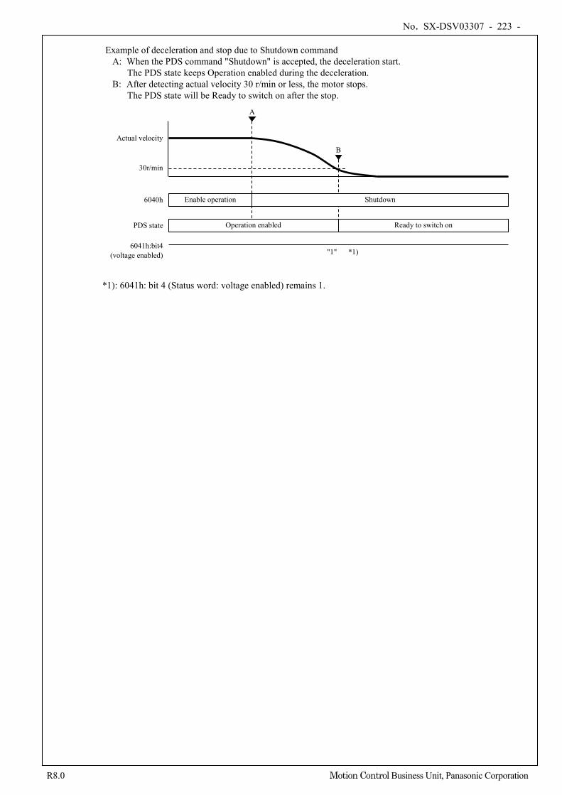
No. SX-DSV03307 - 223 -
R8.0 Motion Control Business Unit, Panasonic Corporation
Example of deceleration and stop due to Shutdown command
A: When the PDS command "Shutdown" is accepted, the deceleration start. The PDS state keeps Operation enabled during the deceleration.
B: After detecting actual velocity 30 r/min or less, the motor stops. The PDS state will be Ready to switch on after the stop.
*1): 6041h: bit 4 (Status word: voltage enabled) remains 1.
Operation enabled Ready to switch on
Enable operation Shutdown 6040h
30r/min
Actual velocity
PDS state
6041h:bit4 (voltage enabled) "1" *1)
A
B
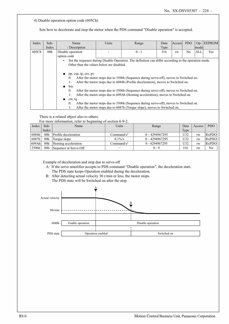
No. SX-DSV03307 - 224 -
R8.0 Motion Control Business Unit, Panasonic Corporation
4) Disable operation option code (605Ch)
Sets how to decelerate and stop the motor when the PDS command "Disable operation" is accepted.
Index Sub-
Index Name
/ Description Units Range Data
Type Access PDO Op-
mode EEPROM
605Ch 00h Disable operation option code
- 0 - 1 I16 rw No ALL Yes
• Set the sequence during Disable Operation. The definition can differ according to the operation mode. Other than the values below are disabled.
■ pp, csp, ip, csv, pv 0: After the motor stops due to 3506h (Sequence during servo-off), moves to Switched on. 1: After the motor stops due to 6084h (Profile deceleration), moves to Switched on.
■ hm 0: After the motor stops due to 3506h (Sequence during servo-off), moves to Switched on. 1: After the motor stops due to 609Ah (Homing acceleration), moves to Switched on.
■ cst, tq 0: After the motor stops due to 3506h (Sequence during servo-off), moves to Switched on. 1: After the motor stops due to 6087h (Torque slope), moves to Switched on.
There is a related object also to others. For more information, refer to beginning of section 6-9-2.
Index Sub- Index
Name Units Range Data Type
Access PDO
6084h 00h Profile deceleration Command/s2 0 – 4294967295 U32 rw RxPDO 6087h 00h Torque slope 0.1%/s 0 – 4294967295 U32 rw RxPDO 609Ah 00h Homing acceleration Command/s2 0 - 4294967295 U32 rw RxPDO 3506h 00h Sequence at Servo-Off - 0 - 9 I16 rw No
Example of deceleration and stop due to servo-off A: If the servo amolifier accepts to PDS command “Disable operation”, the deceleration start.
The PDS state keeps Operation enabled during the deceleration. B: After detecting actual velocity 30 r/min or less, the motor stops.
The PDS state will be Switched on after the stop.
Operation enabled Switched on
Enable operation Disable operation 6040h
30r/min
Actual velocity
PDS state
A
B
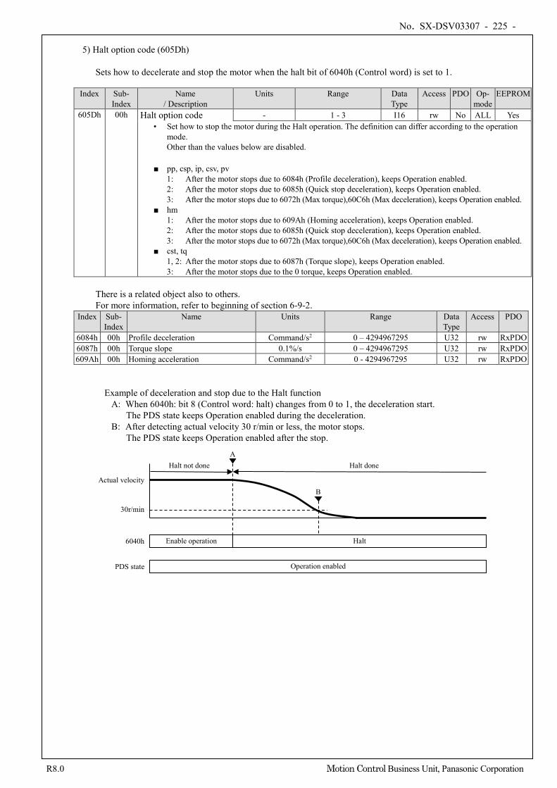
No. SX-DSV03307 - 225 -
R8.0 Motion Control Business Unit, Panasonic Corporation
5) Halt option code (605Dh)
Sets how to decelerate and stop the motor when the halt bit of 6040h (Control word) is set to 1.
Index Sub-
Index Name
/ Description Units Range Data
Type Access PDO Op-
mode EEPROM
605Dh 00h Halt option code - 1 - 3 I16 rw No ALL Yes • Set how to stop the motor during the Halt operation. The definition can differ according to the operation
mode. Other than the values below are disabled.
■ pp, csp, ip, csv, pv 1: After the motor stops due to 6084h (Profile deceleration), keeps Operation enabled. 2: After the motor stops due to 6085h (Quick stop deceleration), keeps Operation enabled. 3: After the motor stops due to 6072h (Max torque),60C6h (Max deceleration), keeps Operation enabled.
■ hm 1: After the motor stops due to 609Ah (Homing acceleration), keeps Operation enabled. 2: After the motor stops due to 6085h (Quick stop deceleration), keeps Operation enabled. 3: After the motor stops due to 6072h (Max torque),60C6h (Max deceleration), keeps Operation enabled.
■ cst, tq 1, 2: After the motor stops due to 6087h (Torque slope), keeps Operation enabled. 3: After the motor stops due to the 0 torque, keeps Operation enabled.
There is a related object also to others. For more information, refer to beginning of section 6-9-2.
Index Sub- Index
Name Units Range Data Type
Access PDO
6084h 00h Profile deceleration Command/s2 0 – 4294967295 U32 rw RxPDO 6087h 00h Torque slope 0.1%/s 0 – 4294967295 U32 rw RxPDO 609Ah 00h Homing acceleration Command/s2 0 - 4294967295 U32 rw RxPDO
Example of deceleration and stop due to the Halt function A: When 6040h: bit 8 (Control word: halt) changes from 0 to 1, the deceleration start.
The PDS state keeps Operation enabled during the deceleration. B: After detecting actual velocity 30 r/min or less, the motor stops.
The PDS state keeps Operation enabled after the stop.
Operation enabled
Enable operation Halt 6040h
30r/min
Actual velocity
PDS state
Halt not done A
B
Halt done
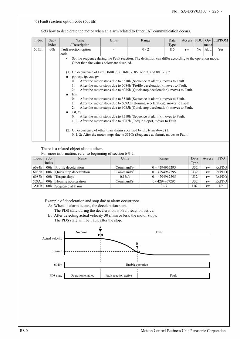
No. SX-DSV03307 - 226 -
R8.0 Motion Control Business Unit, Panasonic Corporation
6) Fault reaction option code (605Eh)
Sets how to decelerate the motor when an alarm related to EtherCAT communication occurs.
Index Sub-
Index Name
/ Description Units Range Data
Type Access PDO Op-
mode EEPROM
605Eh 00h Fault reaction option code
- 0 - 2 I16 rw No ALL Yes
• Set the sequence during the Fault reaction. The definition can differ according to the operation mode. Other than the values below are disabled.
(1) On occurrence of Err80.0-80.7, 81.0-81.7, 85.0-85.7, and 88.0-88.7 ■ pp, csp, ip, csv, pv
0: After the motor stops due to 3510h (Sequence at alarm), moves to Fault. 1: After the motor stops due to 6084h (Profile deceleration), moves to Fault. 2: After the motor stops due to 6085h (Quick stop deceleration), moves to Fault.
■ hm 0: After the motor stops due to 3510h (Sequence at alarm), moves to Fault. 1: After the motor stops due to 609Ah (Homing acceleration), moves to Fault. 2: After the motor stops due to 6085h (Quick stop deceleration), moves to Fault.
■ cst, tq 0: After the motor stops due to 3510h (Sequence at alarm), moves to Fault. 1, 2: After the motor stops due to 6087h (Torque slope), moves to Fault.
(2) On occurrence of other than alarms specified by the term above (1) 0, 1, 2: After the motor stops due to 3510h (Sequence at alarm), moves to Fault.
There is a related object also to others. For more information, refer to beginning of section 6-9-2.
Index Sub- Index
Name Units Range Data Type
Access PDO
6084h 00h Profile deceleration Command/s2 0 – 4294967295 U32 rw RxPDO 6085h 00h Quick stop deceleration Command/s2 0 – 4294967295 U32 rw RxPDO 6087h 00h Torque slope 0.1%/s 0 – 4294967295 U32 rw RxPDO 609Ah 00h Homing acceleration Command/s2 0 - 4294967295 U32 rw RxPDO 3510h 00h Sequence at alarm - 0 - 7 I16 rw No
Example of deceleration and stop due to alarm occurrence A: When an alarm occurs, the deceleration start.
The PDS state during the deceleration is Fault reaction active. B: After detecting actual velocity 30 r/min or less, the motor stops.
The PDS state will be Fault after the stop.
Operation enabled Fault
Enable operation 6040h
30r/min
Actual velocity
PDS state
No error Error A
B
Fault reaction active
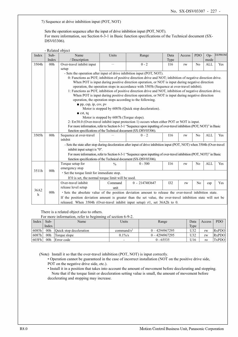
No. SX-DSV03307 - 227 -
R8.0 Motion Control Business Unit, Panasonic Corporation
7) Sequence at drive inhibition input (POT, NOT)
Sets the operation sequence after the input of drive inhibition input (POT, NOT). For more information, see Section 6-3-1 in Basic function specifications of the Technical document (SX-DSV03306).
- Related object
Index Sub- Index
Name / Description
Units Range Data Type
Access PDO Op- mode
EEPROM
3504h 00h Over-travel inhibit input setup
- 0 - 2 I16 rw No ALL Yes
- Sets the operation after input of drive inhibition input (POT, NOT). 0: Functions as POT; inhibition of positive direction drive and NOT; inhibition of negative direction drive.
When POT is input during positive direction operation, or NOT is input during negative direction operation, the operation stops in accordance with 3505h (Sequence at over-travel inhibit).
1: Functions as POT, inhibition of positive direction drive and NOT, inhibition of negative direction drive. When POT is input during positive direction operation, or NOT is input during negative direction operation, the operation stops according to the following.
■ pp, csp, ip, csv, pv Motor is stopped by 6085h (Quick stop deceleration).
■ cst, tq Motor is stopped by 6087h (Torque slope).
2: Err38.0 (Over-travel inhibit input protection 1) occurs when either POT or NOT is input. For more information, refer to Section 6-3-1 “Sequence upon inputting of over-travel inhibition (POT, NOT)” in Basic function specifications of the Technical document (SX-DSV03306).
3505h 00h Sequence at over-travel inhibit
- 0 – 2 I16 rw No ALL Yes
- Sets the state after stop during deceleration after input of drive inhibition input (POT, NOT) when 3504h (Over-travel inhibit input setup) is "0". For more information, refer to Section 6-3-1 “Sequence upon inputting of over-travel inhibition (POT, NOT)” in Basic function specifications of the Technical document (SX-DSV03306).
3511h 00h
Torque setup for emergency stop
% 0 - 500 I16 rw No ALL Yes
・Set the torque limit for immediate stop. If 0 is set, the normal torque limit will be used.
36A2h 00h
Over-travel inhibit release level setup
Command unit
0 - 2147483647 I32 rw No csp Yes
・Sets the absolute value of the position deviation amount to release the over-travel inhibition state. If the position deviation amount is greater than the set value, the over-travel inhibition state will not be released. When 3504h (Over-travel inhibit input setup) ≠1, set 36A2h to 0.
There is a related object also to others. For more information, refer to beginning of section 6-9-2.
Index Sub- Index
Name Units Range Data Type
Access PDO
6085h 00h Quick stop deceleration command/s2 0 – 4294967295 U32 rw RxPDO 6087h 00h Torque slope 0.1%/s 0 – 4294967295 U32 rw RxPDO 603Fh 00h Error code - 0 - 65535 U16 ro TxPDO
(Note) Install it so that the over-travel inhibition (POT, NOT) is input correctly. • Operation cannot be guaranteed in the case of incorrect installation (NOT on the positive drive side, POT on the negative drive side, etc.). • Install it in a position that takes into account the amount of movement before decelerating and stopping. Note that if the torque limit or deceleration setting value is small, the amount of movement before decelerating and stopping may increase.
No. SX-DSV03307 - 228 -
R8.0 Motion Control Business Unit, Panasonic Corporation
6-9-3 Digital Inputs/Digital Outputs
The bits of Digital inputs/Digital outputs represent the input state of positive limit switch(POT), negative limit switch(NOT), and home switch(HOME), each logical input state of EXT1 - EXT2, E-STOP and SI-MON1 - SI-MON5 and logical output state of EX-OUT1 and set_brake of all the function signals allocated by the servo parameters 3400h to 3407h, 3410h, and 3411h to3413h.
Here, for information on the signal allocation and logical setting, refer to the technical document "Basic function specifications"(SX-DSV03306).
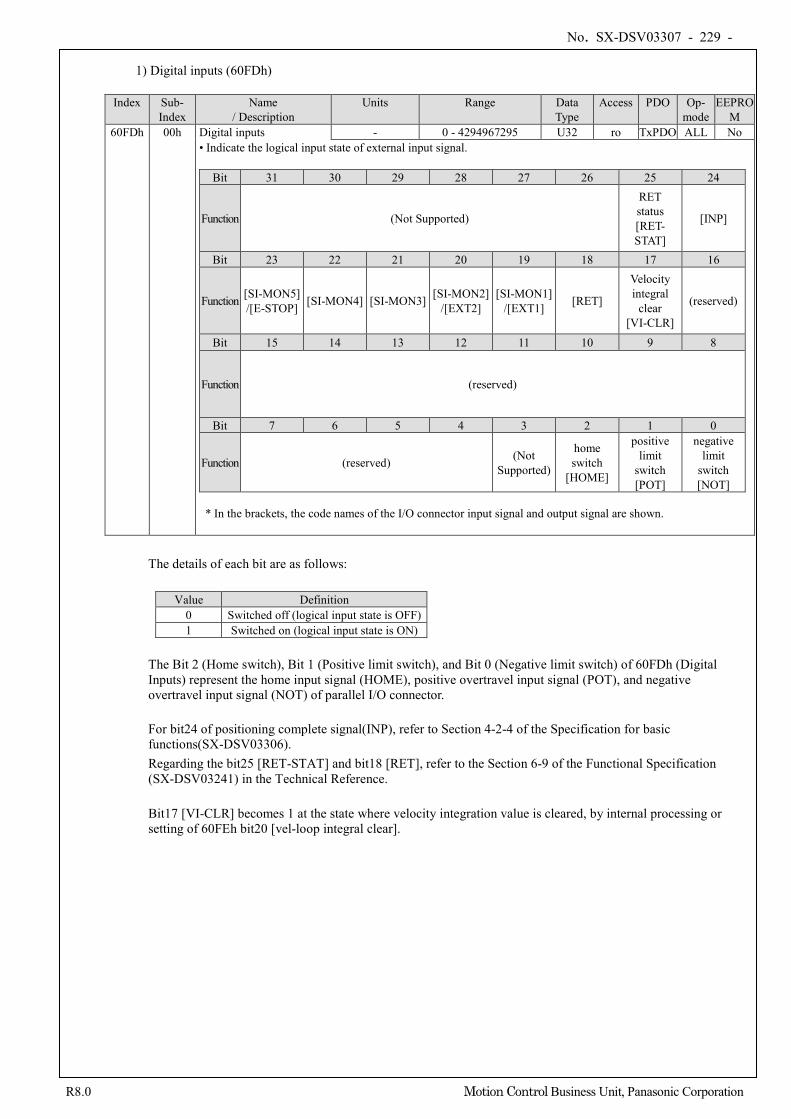
No. SX-DSV03307 - 229 -
R8.0 Motion Control Business Unit, Panasonic Corporation
1) Digital inputs (60FDh)
Index Sub-
Index Name
/ Description Units Range Data
Type Access PDO Op-
mode EEPRO
M 60FDh 00h Digital inputs - 0 - 4294967295 U32 ro TxPDO ALL No
• Indicate the logical input state of external input signal.
Bit 31 30 29 28 27 26 25 24
Function (Not Supported)
RET status [RET- STAT]
[INP]
Bit 23 22 21 20 19 18 17 16
Function [SI-MON5] /[E-STOP] [SI-MON4] [SI-MON3] [SI-MON2]
/[EXT2] [SI-MON1]
/[EXT1] [RET]
Velocity integral
clear [VI-CLR]
(reserved)
Bit 15 14 13 12 11 10 9 8
Function (reserved)
Bit 7 6 5 4 3 2 1 0
Function (reserved) (Not Supported)
home switch
[HOME]
positive limit
switch [POT]
negative limit
switch [NOT]
* In the brackets, the code names of the I/O connector input signal and output signal are shown.
The details of each bit are as follows:
Value Definition 0 Switched off (logical input state is OFF) 1 Switched on (logical input state is ON)
The Bit 2 (Home switch), Bit 1 (Positive limit switch), and Bit 0 (Negative limit switch) of 60FDh (Digital Inputs) represent the home input signal (HOME), positive overtravel input signal (POT), and negative overtravel input signal (NOT) of parallel I/O connector.
For bit24 of positioning complete signal(INP), refer to Section 4-2-4 of the Specification for basic functions(SX-DSV03306). Regarding the bit25 [RET-STAT] and bit18 [RET], refer to the Section 6-9 of the Functional Specification (SX-DSV03241) in the Technical Reference. Bit17 [VI-CLR] becomes 1 at the state where velocity integration value is cleared, by internal processing or setting of 60FEh bit20 [vel-loop integral clear].
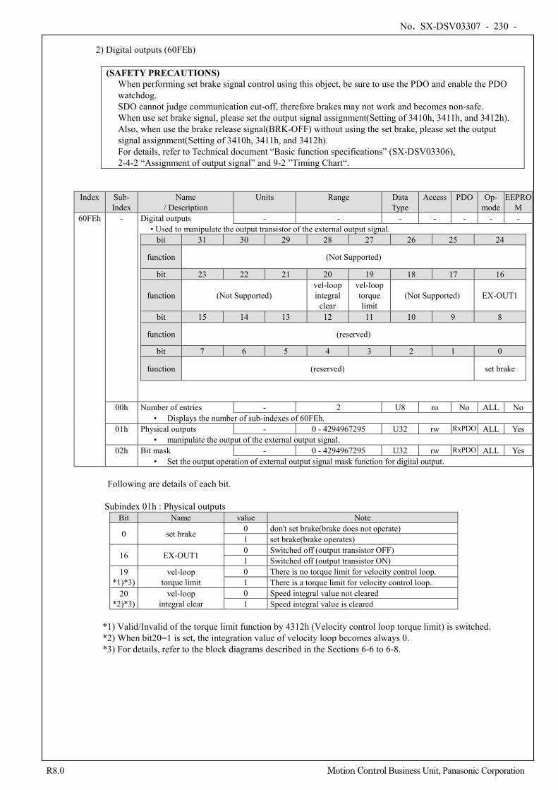
No. SX-DSV03307 - 230 -
R8.0 Motion Control Business Unit, Panasonic Corporation
2) Digital outputs (60FEh)
(SAFETY PRECAUTIONS) When performing set brake signal control using this object, be sure to use the PDO and enable the PDO watchdog. SDO cannot judge communication cut-off, therefore brakes may not work and becomes non-safe. When use set brake signal, please set the output signal assignment(Setting of 3410h, 3411h, and 3412h). Also, when use the brake release signal(BRK-OFF) without using the set brake, please set the output signal assignment(Setting of 3410h, 3411h, and 3412h). For details, refer to Technical document “Basic function specifications” (SX-DSV03306), 2-4-2 “Assignment of output signal” and 9-2 ”Timing Chart“.
Index Sub- Index
Name / Description
Units Range Data Type
Access PDO Op- mode
EEPROM
60FEh - Digital outputs - - - - - - - • Used to manipulate the output transistor of the external output signal.
bit 31 30 29 28 27 26 25 24
function (Not Supported)
bit 23 22 21 20 19 18 17 16
function (Not Supported) vel-loop integral
clear
vel-loop torque limit
(Not Supported) EX-OUT1
bit 15 14 13 12 11 10 9 8
function (reserved)
bit 7 6 5 4 3 2 1 0
function (reserved) set brake
00h Number of entries - 2 U8 ro No ALL No • Displays the number of sub-indexes of 60FEh.
01h Physical outputs - 0 - 4294967295 U32 rw RxPDO ALL Yes • manipulate the output of the external output signal.
02h Bit mask - 0 - 4294967295 U32 rw RxPDO ALL Yes • Set the output operation of external output signal mask function for digital output.
Following are details of each bit.
Subindex 01h : Physical outputs Bit Name value Note
0 set brake 0 don't set brake(brake does not operate) 1 set brake(brake operates)
16 EX-OUT1 0 Switched off (output transistor OFF) 1 Switched off (output transistor ON)
19 *1)*3)
vel-loop torque limit
0 There is no torque limit for velocity control loop. 1 There is a torque limit for velocity control loop.
20 *2)*3)
vel-loop integral clear
0 Speed integral value not cleared 1 Speed integral value is cleared
*1) Valid/Invalid of the torque limit function by 4312h (Velocity control loop torque limit) is switched. *2) When bit20=1 is set, the integration value of velocity loop becomes always 0. *3) For details, refer to the block diagrams described in the Sections 6-6 to 6-8.
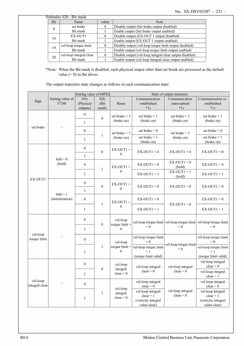
No. SX-DSV03307 - 231 -
R8.0 Motion Control Business Unit, Panasonic Corporation
Subindex 02h : Bit mask Bit Name value Note
0 set brake Bit mask
0 Disable output (Set brake output disabled) 1 Enable output (Set brake output enabled)
16 EX-OUT1 Bit mask
0 Disable output (EX-OUT 1 output disabled) 1 Enable output (EX-OUT 1 output enabled)
19 vel-loop torque limit Bit mask
0 Disable output (vel-loop torque limit output disabled) 1 Enable output (vel-loop torque limit output enabled)
20 vel-loop integral clear Bit mask
0 Disable output (vel-loop integral clear output disabled) 1 Enable output (vel-loop integral clear output enabled)
*Note: When the Bit mask is disabled, each physical output other than set break are processed as the default value (= 0) in the driver.
The output transistor state changes as follows in each communication state:
Sign Setting value of 3724h
Setting value of 60FEh State of output transistor 01h
(Physical outputs)
02h (Bit
mask) Reset
Communication established
*1)
Communication intercepterd
*1)
Communication re-established
*1)
set brake -
0 0 set brake = 1
(brake on) set brake = 1
(brake on) set brake = 1
(brake on) set brake = 1
(brake on) 1
0 1 set brake = 1
(brake on)
set brake = 0 set brake = 1 (brake on)
set brake = 0
1 set brake = 1 (brake on)
set brake = 1 (brake on)
EX-OUT1
bit0 = 0 (hold)
0 0 EX-OUT1 =
0 EX-OUT1 = 0 EX-OUT1 = 0 EX-OUT1 = 0 1
0 1 EX-OUT1 =
0
EX-OUT1 = 0 EX-OUT1 = 0 (hold) EX-OUT1 = 0
1 EX-OUT1 = 1 EX-OUT1 = 1 (hold) EX-OUT1 = 1
bit0 = 1 (initialization)
0 0 EX-OUT1 =
0 EX-OUT1 = 0 EX-OUT1 = 0 EX-OUT1 = 0 1
0 1 EX-OUT1 =
0
EX-OUT1 = 0 EX-OUT1 = 0
EX-OUT1 = 0
1 EX-OUT1 = 1 EX-OUT1 = 1
vel-loop torque limit -
0 0
vel-loop torque limit =
0
vel-loop torque limit = 0
vel-loop torque limit = 0
vel-loop torque limit = 0
1
0
1 vel-loop
torque limit = 0
vel-loop torque limit = 0
vel-loop torque limit = 0
vel-loop torque limit = 0
1 vel-loop torque limit
= 1 (torque limit valid)
vel-loop torque limit = 1
(torque limit valid)
vel-loop integral clear -
0 0
vel-loop integral clear = 0
vel-loop integral clear = 0
vel-loop integral clear = 0
vel-loop integral clear = 0
1 vel-loop integral clear = 1
0
1 vel-loop integral clear = 0
vel-loop integral clear = 0
vel-loop integral clear = 0
vel-loop integral clear = 0
1
vel-loop integral clear = 1
(velocity integral value clear)
vel-loop integral clear = 1
(velocity integral value clear)
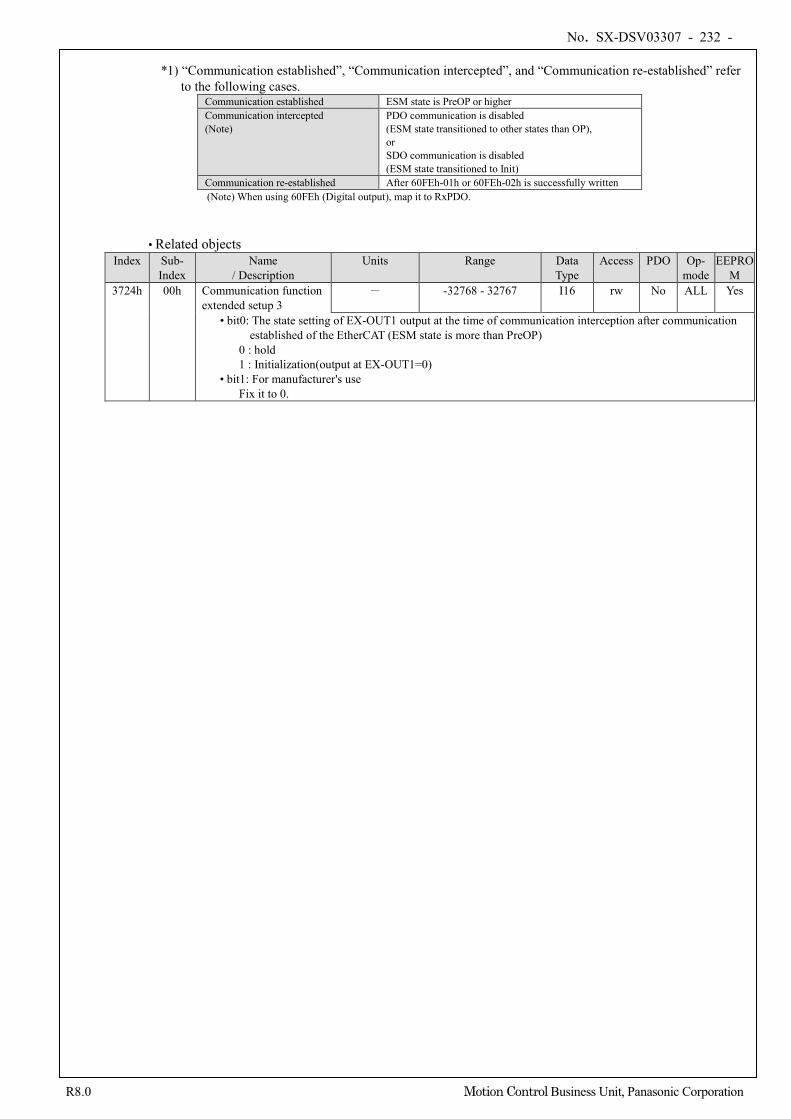
No. SX-DSV03307 - 232 -
R8.0 Motion Control Business Unit, Panasonic Corporation
*1) “Communication established”, “Communication intercepted”, and “Communication re-established” refer
to the following cases. Communication established ESM state is PreOP or higher Communication intercepted (Note)
PDO communication is disabled (ESM state transitioned to other states than OP), or SDO communication is disabled (ESM state transitioned to Init)
Communication re-established After 60FEh-01h or 60FEh-02h is successfully written (Note) When using 60FEh (Digital output), map it to RxPDO.
• Related objects Index Sub-
Index Name
/ Description Units Range Data
Type Access PDO Op-
mode EEPRO
M 3724h 00h Communication function
extended setup 3 - -32768 - 32767 I16 rw No ALL Yes
• bit0: The state setting of EX-OUT1 output at the time of communication interception after communication established of the EtherCAT (ESM state is more than PreOP)
0 : hold 1 : Initialization(output at EX-OUT1=0)
• bit1: For manufacturer's use Fix it to 0.
No. SX-DSV03307 - 233 -
R8.0 Motion Control Business Unit, Panasonic Corporation
6-9-4 Position information
1) Initialization timing of position information
This servo driver initializes(preset) position information object at the following timing. ・Initialization timing (conditions)
- At the time of the control power supply ON - When establishing communication (when changing ESM state from Init to PreOP) - When returning to origin is completed - When clearing absolute multi-turn from PANATERM or EtherCAT communication - When PANATERM operation(test run function, frequency response analyzing function,
Z phase search,fit gain) is completed. - When setting pin assign by PANATERM. - When Err27.4 (Command error protection) occurs
・Object to be initialized - 4F04h(Position command internal value(after filtering)) - 6062h (Position demand value) - 6063h (Position actual internal value) - 6064h (Position actual value) - 60FCh (Position demand internal value)
These objects are based on 6063h (Position actual internal value) which shows the feedback position of a motor, the code translation by the electronic gear function, Polarity, and Home offset which are mentioned later are considered, and it is initialized (preset). Also,Changing the set value of electronic gear ratio,Polarity,and Home offset is reflected at the timing later described in this section. Please confirm "4) Initialization of the absolute feedback scale " mentioned later about notes at the time of using an absolute feedback scale.
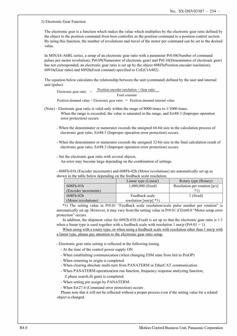
No. SX-DSV03307 - 234 -
R8.0 Motion Control Business Unit, Panasonic Corporation
2) Electronic Gear Function
The electronic gear is a function which makes the value which multiplies by the electronic gear ratio defined by the object to the position command from host controller as the position command to a position control section. By using this function, the number of revolutions and travel of the motor per command can be set to the desired value.
In MINAS-A6BL series, a setup of an electronic gear ratio with a parameter Pr0.08(Number of command pulses per motor revolution), Pr0.09(Numerator of electronic gear) and Pr0.10(Denominator of electronic gear) has not corresponded, an electronic gear ratio is set up by the object 608Fh(Position encoder resolution), 6091h(Gear ratio) and 6092h(Feed constant) specified to CoE(CiA402).
The equation below calculates the relationship between the unit (command) defined by the user and internal unit (pulse):
(Note) - Electronic gear ratio is valid only within the range of 8000 times to 1/1000 times. When the range is exceeded, the value is saturated in the range, and Err88.3 (Improper operation error protection) occurs.
- When the denominator or numerator exceeds the unsigned 64-bit size in the calculation process of electronic gear ratio, Err88.3 (Improper operation error protection) occurs.
- When the denominator or numerator exceeds the unsigned 32-bit size in the final calculation result of
electronic gear ratio, Err88.3 (Improper operation error protection) occurs. - Set the electronic gear ratio with several objects.
An error may become large depending on the combination of settings.
- 608Fh-01h (Encoder increments) and 608Fh-02h (Motor revolutions) are automatically set up as shown in the table below depending on the feedback scale resolution.
Linear type (Linear) Rotary type (Rotary) 608Fh-01h (Encoder increments)
1,000,000 (fixed) Resolution per rotation [p/r] *1)
608Fh-02h (Motor revolutions)
Feedback scale resolution [nm/p] *1)
1 (fixed)
*1) The setting value in Pr9.01 “Feedback scale resolution/scale pulse number per rotation” is automatically set up. However, it may vary from the setting value in Pr9.01 if Err60.0 “Motor setup error protection” occurs.
In addition, the shipment value for 6092h-01h (Feed) is set up so that the electronic gear ratio is 1:1 when a linear type is used together with a feedback scale with resolution 1 nm/p (Pr9.01 = 1).
When using with a rotary type, or when using a feedback scale with resolution other than 1 nm/p with a linear type, please pay attention to the electronic gear ratio setup.
- Electronic gear ratio setting is reflected at the following timing.
- At the time of the control power supply ON - When establishing communication (when changing ESM state from Init to PreOP) - When returning to origin is completed - When clearing absolute multi-turn from PANATERM or EtherCAT communication - When PANATERM operation(test run function, frequency response analyzing function,
Z phase search,fit gain) is completed. - When setting pin assign by PANATERM. - When Err27.4 (Command error protection) occurs Please note that it will not be reflected without a proper process even if the setting value for a related
object is changed.
Position demand value × Electronic gear ratio = Position demand internal value Feed constant
Position encoder resolution × Gear ratio Electronic gear ratio =
No. SX-DSV03307 - 235 -
R8.0 Motion Control Business Unit, Panasonic Corporation
- In the position information initialization when Init changes to PreOP in the absolute feedback scale
mode, make a setting so that the value of "Absolute feedback scale position [pulse/unit]/Electronic gear ratio" is in the range from -231 (-2147483648) to +231-1 (2147483647). Err29.1 (Counter overflow protection 1) occurs if this range is exceeded. Check the operation range of the absolute feedback scale position and the electronic gear ratio.
- The unit of the movement amount setting of the test run function by the setup support tool
PANATERM is [command unit]. Note that operations are different from those of the MINAS-A5BL series.
- Communication cycle 125µs is supported only if the electronic gear ratio is 1:1. Operations when the electronic gear ratio is other than 1:1 is not guaranteed.
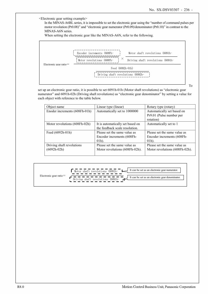
No. SX-DSV03307 - 236 -
R8.0 Motion Control Business Unit, Panasonic Corporation
<Electronic gear setting example>
In the MINAS-A6BL series, it is impossible to set the electronic gear using the “number of command pulses per motor revolution (Pr0.08)” and “electronic gear numerator (Pr0.09)/denominator (Pr0.10)” in contrast to the MINAS-A6N series. When setting the electronic gear like the MINAS-A6N, refer to the following.
To set up an electronic gear ratio, it is possible to set 6091h-01h (Motor shaft revolutions) as “electronic gear numerator” and 6091h-02h (Driving shaft revolutions) as “electronic gear denominator” by setting a value for each object with reference to the table below.
Object name Linear type (linear) Rotary type (rotary) Enoder increments (608Fh-01h) Automatically set to 1000000 Automatically set based on
Pr9.01 (Pulse number per rotation)
Motor revolutions (608Fh-02h) It is automatically set based on the feedback scale resolution.
Automatically set to 1
Feed (6092h-01h) Please set the same value as Encoder increments (608Fh-01h).
Please set the same value as Encoder increments (608Fh-01h).
Driving shaft revolutions (6092h-02h)
Please set the same value as Motor revolutions (608Fh-02h).
Please set the same value as Motor revolutions (608Fh-02h).
Electronic gear ratio=
×
Encoder increments (608Fh-
Motor revolutions (608Fh-
Driving shaft revolutions (6091h-
Motor shaft revolutions (6091h-
Feed (6092h-01h)
Driving shaft revolutions (6092h-
)
Electronic gear ratio=
Motor shaft revolutions (6091h-
Driving shaft revolutions (6091h-It can be set as an electronic gear denominator.
It can be set as an electronic gear numerator.
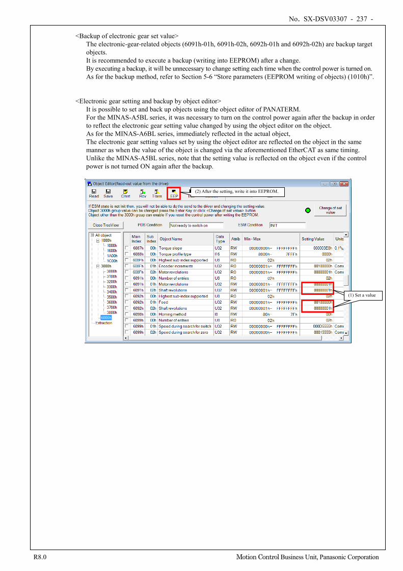
No. SX-DSV03307 - 237 -
R8.0 Motion Control Business Unit, Panasonic Corporation
<Backup of electronic gear set value>
The electronic-gear-related objects (6091h-01h, 6091h-02h, 6092h-01h and 6092h-02h) are backup target objects. It is recommended to execute a backup (writing into EEPROM) after a change. By executing a backup, it will be unnecessary to change setting each time when the control power is turned on. As for the backup method, refer to Section 5-6 “Store parameters (EEPROM writing of objects) (1010h)”.
<Electronic gear setting and backup by object editor> It is possible to set and back up objects using the object editor of PANATERM. For the MINAS-A5BL series, it was necessary to turn on the control power again after the backup in order to reflect the electronic gear setting value changed by using the object editor on the object. As for the MINAS-A6BL series, immediately reflected in the actual object, The electronic gear setting values set by using the object editor are reflected on the object in the same manner as when the value of the object is changed via the aforementioned EtherCAT as same timing. Unlike the MINAS-A5BL series, note that the setting value is reflected on the object even if the control power is not turned ON again after the backup.
①値を設定 (1) Set a value
(2) After the setting, write it into EEPROM.
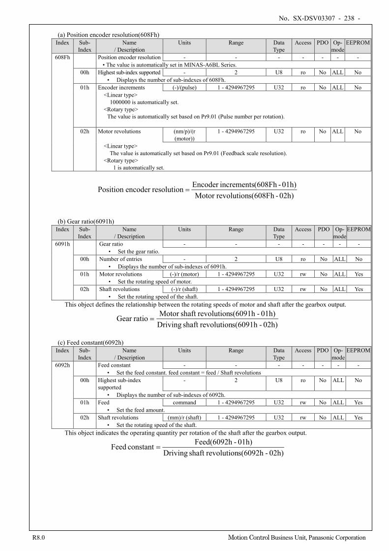
No. SX-DSV03307 - 238 -
R8.0 Motion Control Business Unit, Panasonic Corporation
(a) Position encoder resolution(608Fh)
Index Sub- Index
Name / Description
Units Range Data Type
Access PDO Op- mode
EEPROM
608Fh Position encoder resolution - - - - - - - • The value is automatically set in MINAS-A6BL Series.
00h Highest sub-index supported - 2 U8 ro No ALL No • Displays the number of sub-indexes of 608Fh.
01h Encoder increments (-)/(pulse) 1 - 4294967295 U32 ro No ALL No <Linear type> 1000000 is automatically set. <Rotary type>
The value is automatically set based on Pr9.01 (Pulse number per rotation).
02h Motor revolutions (nm/p)/(r (motor))
1 - 4294967295 U32 ro No ALL No
<Linear type> The value is automatically set based on Pr9.01 (Feedback scale resolution). <Rotary type> 1 is automatically set.
02h)-s(608FhrevolutionMotor 01h)-(608FhincrementsEncoder resolutionencoder Position =
(b) Gear ratio(6091h) Index Sub-
Index Name
/ Description Units Range Data
Type Access PDO Op-
mode EEPROM
6091h Gear ratio - - - - - - - • Set the gear ratio.
00h Number of entries - 2 U8 ro No ALL No • Displays the number of sub-indexes of 6091h.
01h Motor revolutions (-)/r (motor) 1 - 4294967295 U32 rw No ALL Yes • Set the rotating speed of motor.
02h Shaft revolutions (-)/r (shaft) 1 - 4294967295 U32 rw No ALL Yes • Set the rotating speed of the shaft.
This object defines the relationship between the rotating speeds of motor and shaft after the gearbox output.
02h)-s(6091hrevolutionshaft Driving01h)-s(6091hrevolutionshaft Motor ratioGear =
(c) Feed constant(6092h)
Index Sub- Index
Name / Description
Units Range Data Type
Access PDO Op- mode
EEPROM
6092h Feed constant - - - - - - - • Set the feed constant. feed constant = feed / Shaft revolutions
00h Highest sub-index supported
- 2 U8 ro No ALL No
• Displays the number of sub-indexes of 6092h. 01h Feed command 1 - 4294967295 U32 rw No ALL Yes
• Set the feed amount. 02h Shaft revolutions (mm)/r (shaft) 1 - 4294967295 U32 rw No ALL Yes
• Set the rotating speed of the shaft. This object indicates the operating quantity per rotation of the shaft after the gearbox output.
02h)-s(6092hrevolutionshaft Driving01h)-Feed(6092hconstant Feed =
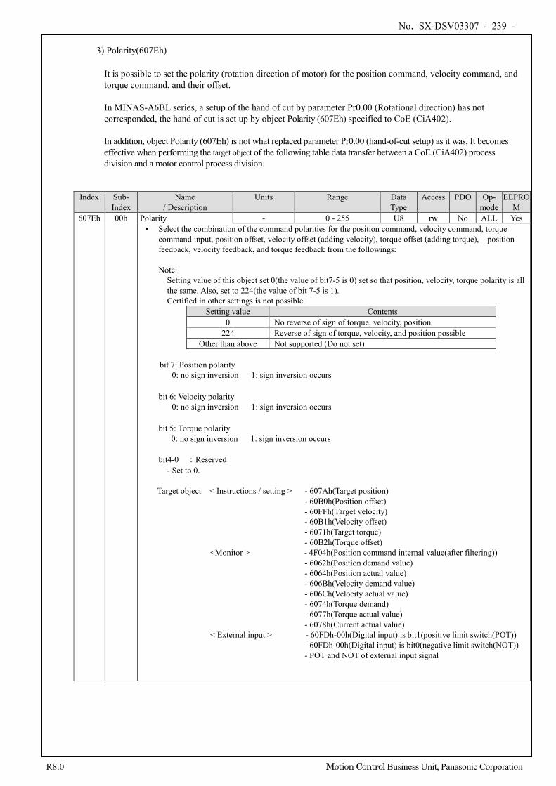
No. SX-DSV03307 - 239 -
R8.0 Motion Control Business Unit, Panasonic Corporation
3) Polarity(607Eh)
It is possible to set the polarity (rotation direction of motor) for the position command, velocity command, and torque command, and their offset.
In MINAS-A6BL series, a setup of the hand of cut by parameter Pr0.00 (Rotational direction) has not corresponded, the hand of cut is set up by object Polarity (607Eh) specified to CoE (CiA402).
In addition, object Polarity (607Eh) is not what replaced parameter Pr0.00 (hand-of-cut setup) as it was, It becomes effective when performing the target object of the following table data transfer between a CoE (CiA402) process division and a motor control process division.
Index Sub- Index
Name / Description
Units Range Data Type
Access PDO Op- mode
EEPROM
607Eh 00h Polarity - 0 - 255 U8 rw No ALL Yes • Select the combination of the command polarities for the position command, velocity command, torque
command input, position offset, velocity offset (adding velocity), torque offset (adding torque), position feedback, velocity feedback, and torque feedback from the followings:
Note:
Setting value of this object set 0(the value of bit7-5 is 0) set so that position, velocity, torque polarity is all the same. Also, set to 224(the value of bit 7-5 is 1). Certified in other settings is not possible.
Setting value Contents 0 No reverse of sign of torque, velocity, position
224 Reverse of sign of torque, velocity, and position possible Other than above Not supported (Do not set)
bit 7: Position polarity 0: no sign inversion 1: sign inversion occurs
bit 6: Velocity polarity 0: no sign inversion 1: sign inversion occurs
bit 5: Torque polarity 0: no sign inversion 1: sign inversion occurs
bit4-0 :Reserved
- Set to 0.
Target object < Instructions / setting > - 607Ah(Target position) - 60B0h(Position offset) - 60FFh(Target velocity) - 60B1h(Velocity offset) - 6071h(Target torque) - 60B2h(Torque offset)
<Monitor > - 4F04h(Position command internal value(after filtering)) - 6062h(Position demand value) - 6064h(Position actual value) - 606Bh(Velocity demand value) - 606Ch(Velocity actual value) - 6074h(Torque demand) - 6077h(Torque actual value) - 6078h(Current actual value)
< External input > - 60FDh-00h(Digital input) is bit1(positive limit switch(POT)) - 60FDh-00h(Digital input) is bit0(negative limit switch(NOT)) - POT and NOT of external input signal
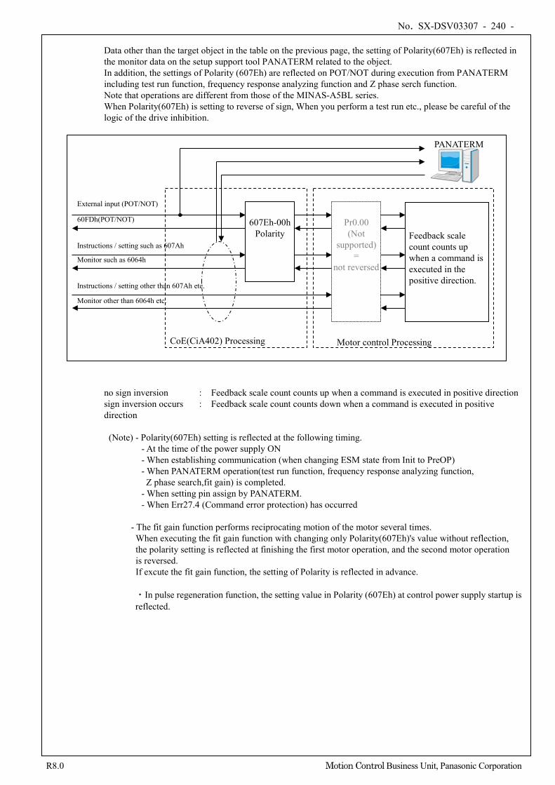
No. SX-DSV03307 - 240 -
R8.0 Motion Control Business Unit, Panasonic Corporation
Data other than the target object in the table on the previous page, the setting of Polarity(607Eh) is reflected in the monitor data on the setup support tool PANATERM related to the object. In addition, the settings of Polarity (607Eh) are reflected on POT/NOT during execution from PANATERM including test run function, frequency response analyzing function and Z phase serch function. Note that operations are different from those of the MINAS-A5BL series. When Polarity(607Eh) is setting to reverse of sign, When you perform a test run etc., please be careful of the logic of the drive inhibition.
no sign inversion : Feedback scale count counts up when a command is executed in positive direction sign inversion occurs : Feedback scale count counts down when a command is executed in positive direction
(Note) - Polarity(607Eh) setting is reflected at the following timing.
- At the time of the power supply ON - When establishing communication (when changing ESM state from Init to PreOP) - When PANATERM operation(test run function, frequency response analyzing function, Z phase search,fit gain) is completed. - When setting pin assign by PANATERM. - When Err27.4 (Command error protection) has occurred
- The fit gain function performs reciprocating motion of the motor several times. When executing the fit gain function with changing only Polarity(607Eh)'s value without reflection, the polarity setting is reflected at finishing the first motor operation, and the second motor operation is reversed. If excute the fit gain function, the setting of Polarity is reflected in advance. ・In pulse regeneration function, the setting value in Polarity (607Eh) at control power supply startup is reflected.
PANATERM
607Eh-00h
Polarity 60FDh(POT/NOT)
Pr0.00 (Not
supported) =
not reversed
Motor control Processing CoE(CiA402) Processing
Instructions / setting such as 607Ah
External input (POT/NOT)
Monitor such as 6064h
Instructions / setting other than 607Ah etc. Monitor other than 6064h etc.
Feedback scale count counts up when a command is executed in the positive direction.
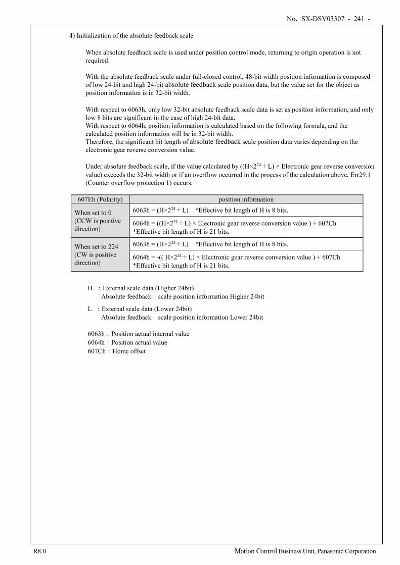
No. SX-DSV03307 - 241 -
R8.0 Motion Control Business Unit, Panasonic Corporation
4) Initialization of the absolute feedback scale
When absolute feedback scale is used under position control mode, returning to origin operation is not required. With the absolute feedback scale under full-closed control, 48-bit width position information is composed of low 24-bit and high 24-bit absolute feedback scale position data, but the value set for the object as position information is in 32-bit width.
With respect to 6063h, only low 32-bit absolute feedback scale data is set as position information, and only low 8 bits are significant in the case of high 24-bit data. With respect to 6064h, position information is calculated based on the following formula, and the calculated position information will be in 32-bit width. Therefore, the significant bit length of absolute feedback scale position data varies depending on the electronic gear reverse conversion value. Under absolute feedback scale, if the value calculated by ((H×224+L) × Electronic gear reverse conversion value) exceeds the 32-bit width or if an overflow occurred in the process of the calculation above, Err29.1 (Counter overflow protection 1) occurs.
607Eh (Polarity) position information
When set to 0 (CCW is positive direction)
6063h = (H×224+L) *Effective bit length of H is 8 bits.
6064h = ((H×224+L) × Electronic gear reverse conversion value ) + 607Ch *Effective bit length of H is 21 bits.
When set to 224 (CW is positive direction)
6063h = (H×224+L) *Effective bit length of H is 8 bits.
6064h = -(( H×224+L) × Electronic gear reverse conversion value ) + 607Ch *Effective bit length of H is 21 bits.
H :External scale data (Higher 24bit) Absolute feedback scale position information Higher 24bit
L :External scale data (Lower 24bit) Absolute feedback scale position information Lower 24bit
6063h:Position actual internal value 6064h:Position actual value 607Ch:Home offset
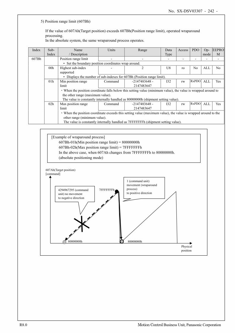
No. SX-DSV03307 - 242 -
R8.0 Motion Control Business Unit, Panasonic Corporation
5) Position range limit (607Bh)
If the value of 607Ah(Target position) exceeds 607Bh(Position range limit), operated wraparound processing. In the absolute system, the same wraparound process operates.
Index Sub-
Index Name
/ Description Units Range Data
Type Access PDO Op-
mode EEPRO
M 607Bh Position range limit - - - - - - -
• Set the boundary position coordinates wrap around. 00h Highest sub-index
supported - 2 U8 ro No ALL No
• Displays the number of sub-indexes for 607Bh (Position range limit). 01h Min position range
limit Command -2147483648 -
2147483647 I32 rw RxPDO ALL Yes
・When the position coordinate falls below this setting value (minimum value), the value is wrapped around to the other range (maximum value). The value is constantly internally handled as 80000000h (shipment setting value).
02h Max position range limit
Command -2147483648 - 2147483647
I32 rw RxPDO ALL Yes
・When the position coordinate exceeds this setting value (maximum value), the value is wrapped around to the other range (minimum value). The value is constantly internally handled as 7FFFFFFFh (shipment setting value).
7FFFFFFFh
80000000h
1 (command unit) movement (wraparound process) to positive direction
4294967295 (command unit) no movement to negative direction
Physical position
80000000h
607Ah(Target position) [command]
[Example of wraparound process] 607Bh-01h(Min position range limit) = 80000000h 607Bh-02h(Max position range limit) = 7FFFFFFFh In the above case, when 607Ah changes from 7FFFFFFFh to 80000000h. (absolute positioning mode)
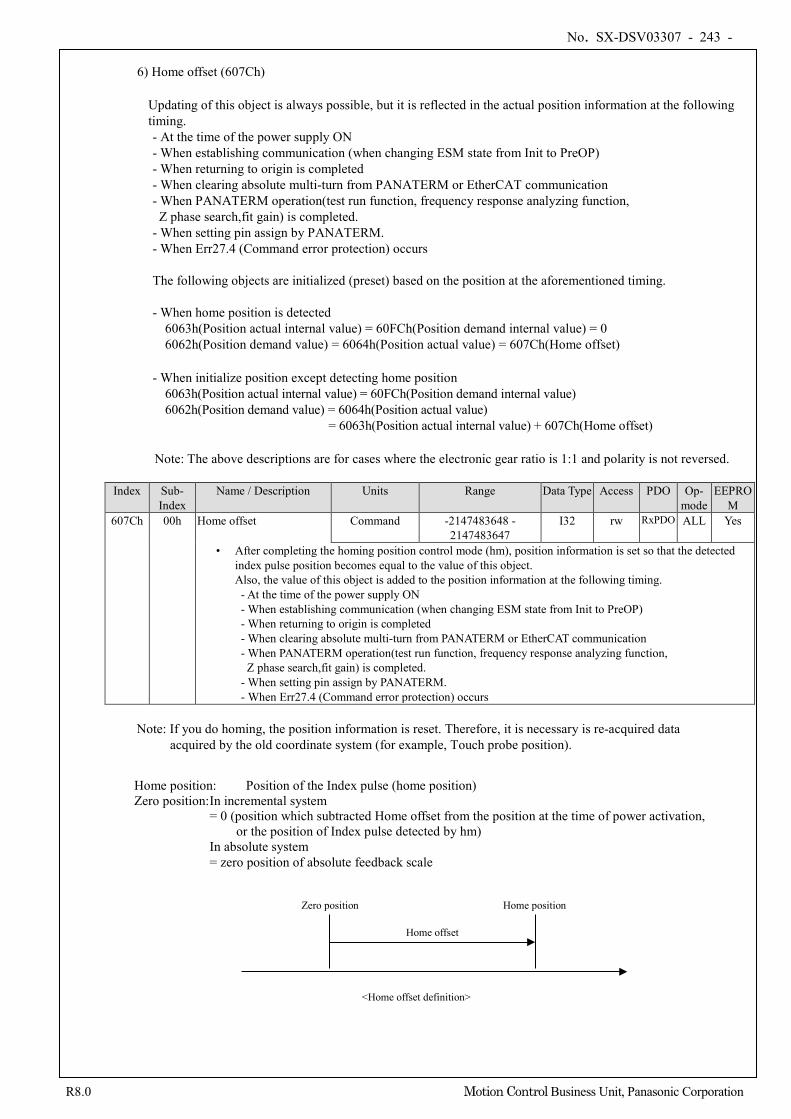
No. SX-DSV03307 - 243 -
R8.0 Motion Control Business Unit, Panasonic Corporation
6) Home offset (607Ch)
Updating of this object is always possible, but it is reflected in the actual position information at the following timing. - At the time of the power supply ON - When establishing communication (when changing ESM state from Init to PreOP) - When returning to origin is completed - When clearing absolute multi-turn from PANATERM or EtherCAT communication - When PANATERM operation(test run function, frequency response analyzing function, Z phase search,fit gain) is completed.
- When setting pin assign by PANATERM. - When Err27.4 (Command error protection) occurs The following objects are initialized (preset) based on the position at the aforementioned timing. - When home position is detected
6063h(Position actual internal value) = 60FCh(Position demand internal value) = 0 6062h(Position demand value) = 6064h(Position actual value) = 607Ch(Home offset)
- When initialize position except detecting home position
6063h(Position actual internal value) = 60FCh(Position demand internal value) 6062h(Position demand value) = 6064h(Position actual value)
= 6063h(Position actual internal value) + 607Ch(Home offset)
Note: The above descriptions are for cases where the electronic gear ratio is 1:1 and polarity is not reversed.
Index Sub- Index
Name / Description Units Range Data Type Access PDO Op- mode
EEPROM
607Ch 00h Home offset Command -2147483648 - 2147483647
I32 rw RxPDO ALL Yes
• After completing the homing position control mode (hm), position information is set so that the detected index pulse position becomes equal to the value of this object. Also, the value of this object is added to the position information at the following timing. - At the time of the power supply ON - When establishing communication (when changing ESM state from Init to PreOP) - When returning to origin is completed - When clearing absolute multi-turn from PANATERM or EtherCAT communication - When PANATERM operation(test run function, frequency response analyzing function,
Z phase search,fit gain) is completed. - When setting pin assign by PANATERM. - When Err27.4 (Command error protection) occurs
Note: If you do homing, the position information is reset. Therefore, it is necessary is re-acquired data
acquired by the old coordinate system (for example, Touch probe position).
Home offset
Zero position Home position
<Home offset definition>
Home position: Position of the Index pulse (home position) Zero position: In incremental system
= 0 (position which subtracted Home offset from the position at the time of power activation, or the position of Index pulse detected by hm) In absolute system = zero position of absolute feedback scale
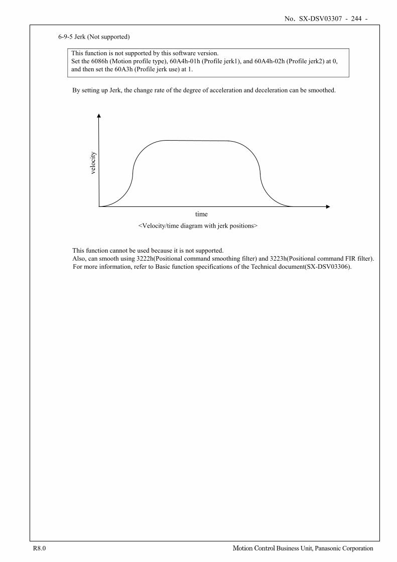
No. SX-DSV03307 - 244 -
R8.0 Motion Control Business Unit, Panasonic Corporation
6-9-5 Jerk (Not supported)
This function is not supported by this software version. Set the 6086h (Motion profile type), 60A4h-01h (Profile jerk1), and 60A4h-02h (Profile jerk2) at 0, and then set the 60A3h (Profile jerk use) at 1.
By setting up Jerk, the change rate of the degree of acceleration and deceleration can be smoothed. This function cannot be used because it is not supported. Also, can smooth using 3222h(Positional command smoothing filter) and 3223h(Positional command FIR filter). For more information, refer to Basic function specifications of the Technical document(SX-DSV03306).
time <Velocity/time diagram with jerk positions>
velo
city
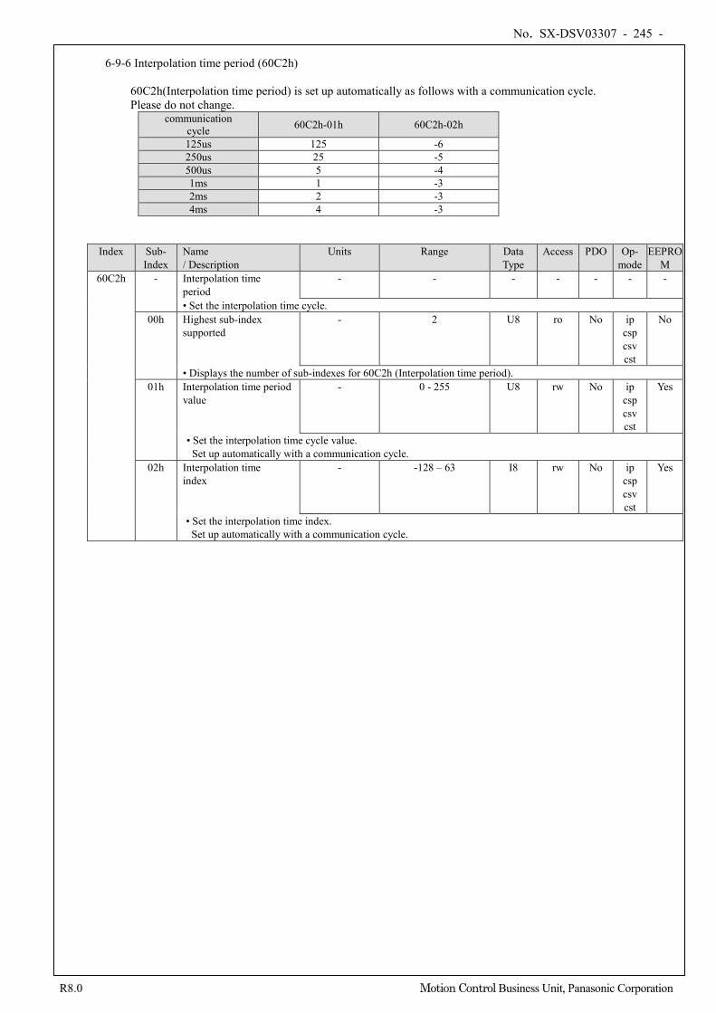
No. SX-DSV03307 - 245 -
R8.0 Motion Control Business Unit, Panasonic Corporation
6-9-6 Interpolation time period (60C2h)
60C2h(Interpolation time period) is set up automatically as follows with a communication cycle. Please do not change.
communication cycle 60C2h-01h 60C2h-02h
125us 125 -6 250us 25 -5 500us 5 -4 1ms 1 -3 2ms 2 -3 4ms 4 -3
Index Sub-
Index Name / Description
Units Range Data Type
Access PDO Op- mode
EEPROM
60C2h - Interpolation time period
- - - - - - -
• Set the interpolation time cycle. 00h Highest sub-index
supported - 2 U8 ro No ip
csp csv cst
No
• Displays the number of sub-indexes for 60C2h (Interpolation time period). 01h Interpolation time period
value - 0 - 255 U8 rw No ip
csp csv cst
Yes
• Set the interpolation time cycle value. Set up automatically with a communication cycle.
02h Interpolation time index
- -128 – 63 I8 rw No ip csp csv cst
Yes
• Set the interpolation time index. Set up automatically with a communication cycle.
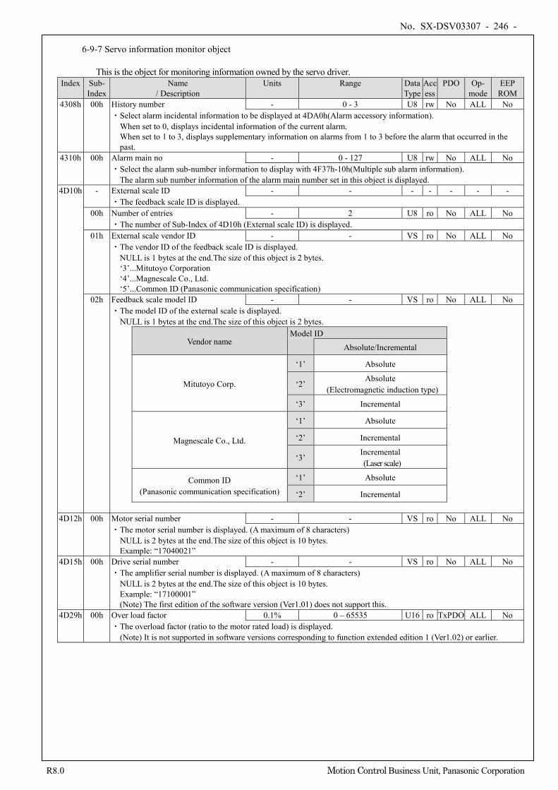
No. SX-DSV03307 - 246 -
R8.0 Motion Control Business Unit, Panasonic Corporation
6-9-7 Servo information monitor object
This is the object for monitoring information owned by the servo driver. Index Sub-
Index Name
/ Description Units Range Data
Type Access
PDO Op- mode
EEP ROM
4308h 00h History number - 0 - 3 U8 rw No ALL No ・Select alarm incidental information to be displayed at 4DA0h(Alarm accessory information). When set to 0, displays incidental information of the current alarm. When set to 1 to 3, displays supplementary information on alarms from 1 to 3 before the alarm that occurred in the
past. 4310h 00h Alarm main no - 0 - 127 U8 rw No ALL No
・Select the alarm sub-number information to display with 4F37h-10h(Multiple sub alarm information). The alarm sub number information of the alarm main number set in this object is displayed.
4D10h - External scale ID - - - - - - - ・The feedback scale ID is displayed.
00h Number of entries - 2 U8 ro No ALL No ・The number of Sub-Index of 4D10h (External scale ID) is displayed.
01h External scale vendor ID - - VS ro No ALL No ・The vendor ID of the feedback scale ID is displayed.
NULL is 1 bytes at the end.The size of this object is 2 bytes. ‘3’...Mitutoyo Corporation ‘4’...Magnescale Co., Ltd. ‘5’...Common ID (Panasonic communication specification)
02h Feedback scale model ID - - VS ro No ALL No ・The model ID of the external scale is displayed. NULL is 1 bytes at the end.The size of this object is 2 bytes.
Vendor name Model ID
Absolute/Incremental
Mitutoyo Corp.
‘1’ Absolute
‘2’ Absolute
(Electromagnetic induction type)
‘3’ Incremental
Magnescale Co., Ltd.
‘1’ Absolute
‘2’ Incremental
‘3’ Incremental (Laser scale)
Common ID (Panasonic communication specification)
‘1’ Absolute
‘2’ Incremental
4D12h 00h Motor serial number - - VS ro No ALL No ・The motor serial number is displayed. (A maximum of 8 characters) NULL is 2 bytes at the end.The size of this object is 10 bytes.
Example: “17040021” 4D15h 00h Drive serial number - - VS ro No ALL No
・The amplifier serial number is displayed. (A maximum of 8 characters) NULL is 2 bytes at the end.The size of this object is 10 bytes.
Example: “17100001” (Note) The first edition of the software version (Ver1.01) does not support this.
4D29h 00h Over load factor 0.1% 0 – 65535 U16 ro TxPDO ALL No ・The overload factor (ratio to the motor rated load) is displayed. (Note) It is not supported in software versions corresponding to function extended edition 1 (Ver1.02) or earlier.
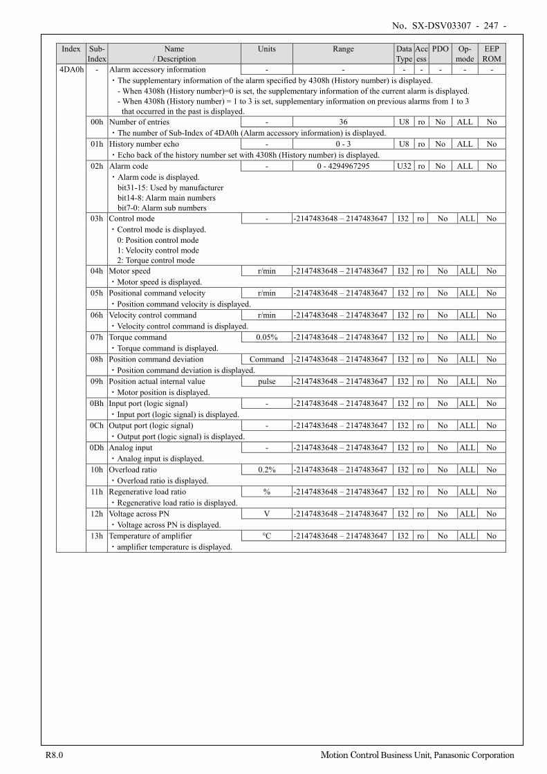
No. SX-DSV03307 - 247 -
R8.0 Motion Control Business Unit, Panasonic Corporation
Index Sub-
Index Name
/ Description Units Range Data
Type Access
PDO Op- mode
EEP ROM
4DA0h
- Alarm accessory information - - - - - - - ・The supplementary information of the alarm specified by 4308h (History number) is displayed.
- When 4308h (History number)=0 is set, the supplementary information of the current alarm is displayed. - When 4308h (History number) = 1 to 3 is set, supplementary information on previous alarms from 1 to 3 that occurred in the past is displayed.
00h Number of entries - 36 U8 ro No ALL No ・The number of Sub-Index of 4DA0h (Alarm accessory information) is displayed.
01h History number echo - 0 - 3 U8 ro No ALL No ・Echo back of the history number set with 4308h (History number) is displayed.
02h Alarm code - 0 - 4294967295 U32 ro No ALL No ・Alarm code is displayed. bit31-15: Used by manufacturer bit14-8: Alarm main numbers bit7-0: Alarm sub numbers
03h Control mode - -2147483648 – 2147483647 I32 ro No ALL No ・Control mode is displayed. 0: Position control mode 1: Velocity control mode 2: Torque control mode
04h Motor speed r/min -2147483648 – 2147483647 I32 ro No ALL No ・Motor speed is displayed.
05h Positional command velocity r/min -2147483648 – 2147483647 I32 ro No ALL No ・Position command velocity is displayed.
06h Velocity control command r/min -2147483648 – 2147483647 I32 ro No ALL No ・Velocity control command is displayed.
07h Torque command 0.05% -2147483648 – 2147483647 I32 ro No ALL No ・Torque command is displayed.
08h Position command deviation Command -2147483648 – 2147483647 I32 ro No ALL No ・Position command deviation is displayed.
09h Position actual internal value pulse -2147483648 – 2147483647 I32 ro No ALL No ・Motor position is displayed.
0Bh Input port (logic signal) - -2147483648 – 2147483647 I32 ro No ALL No ・Input port (logic signal) is displayed.
0Ch Output port (logic signal) - -2147483648 – 2147483647 I32 ro No ALL No ・Output port (logic signal) is displayed.
0Dh Analog input - -2147483648 – 2147483647 I32 ro No ALL No ・Analog input is displayed.
10h Overload ratio 0.2% -2147483648 – 2147483647 I32 ro No ALL No ・Overload ratio is displayed.
11h Regenerative load ratio % -2147483648 – 2147483647 I32 ro No ALL No ・Regenerative load ratio is displayed.
12h Voltage across PN V -2147483648 – 2147483647 I32 ro No ALL No ・Voltage across PN is displayed.
13h Temperature of amplifier °C -2147483648 – 2147483647 I32 ro No ALL No ・amplifier temperature is displayed.
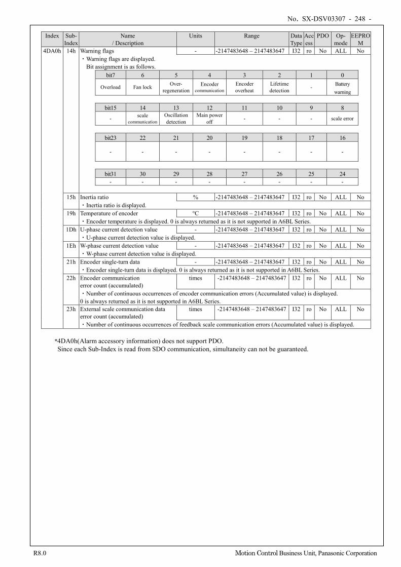
No. SX-DSV03307 - 248 -
R8.0 Motion Control Business Unit, Panasonic Corporation
Index Sub-
Index Name
/ Description Units Range Data
Type Access
PDO Op- mode
EEPROM
4DA0h 14h Warning flags - -2147483648 – 2147483647 I32 ro No ALL No ・Warning flags are displayed. Bit assignment is as follows.
bit7 6 5 4 3 2 1 0
Overload Fan lock Over- regeneration
Encoder communication
Encoder overheat
Lifetime detection
- Battery warning
bit15 14 13 12 11 10 9 8
- scale communication
Oscillation detection
Main power off - - - scale error
bit23 22 21 20 19 18 17 16
- - - - - - - -
bit31 30 29 28 27 26 25 24
- - - - - - - -
15h Inertia ratio % -2147483648 – 2147483647 I32 ro No ALL No ・Inertia ratio is displayed.
19h Temperature of encoder °C -2147483648 – 2147483647 I32 ro No ALL No ・Encoder temperature is displayed. 0 is always returned as it is not supported in A6BL Series.
1Dh U-phase current detection value - -2147483648 – 2147483647 I32 ro No ALL No ・U-phase current detection value is displayed.
1Eh W-phase current detection value - -2147483648 – 2147483647 I32 ro No ALL No ・W-phase current detection value is displayed.
21h Encoder single-turn data - -2147483648 – 2147483647 I32 ro No ALL No ・Encoder single-turn data is displayed. 0 is always returned as it is not supported in A6BL Series.
22h Encoder communication error count (accumulated)
times -2147483648 – 2147483647 I32 ro No ALL No
・Number of continuous occurrences of encoder communication errors (Accumulated value) is displayed. 0 is always returned as it is not supported in A6BL Series.
23h External scale communication data error count (accumulated)
times -2147483648 – 2147483647 I32 ro No ALL No
・Number of continuous occurrences of feedback scale communication errors (Accumulated value) is displayed.
*4DA0h(Alarm accessory information) does not support PDO. Since each Sub-Index is read from SDO communication, simultaneity can not be guaranteed.
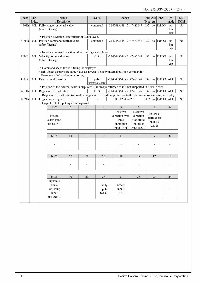
No. SX-DSV03307 - 249 -
R8.0 Motion Control Business Unit, Panasonic Corporation
Index Sub-
Index Name
/ Description Units Range Data
Type Access
PDO Op- mode
EEP ROM
4F01h 00h Following error actual value (after filtering)
command -2147483648 - 2147483647 I32 ro TxPDO pp hm csp
No
・Position deviation (after filtering) is displayed. 4F04h 00h Position command internal value
(after filtering) command -2147483648 - 2147483647 I32 ro TxPDO pp
hm csp
No
・Internal command position (after filtering) is displayed. 4F0Ch 00h Velocity command value
(after filtering) r/min -2147483648 - 2147483647 I32 ro TxPDO pp
hm csp
No
・Command speed (after filtering) is displayed. *This object displays the same value as 4FA5h (Velocity internal position command).
Please use 4FA5h when monitoring. 4F0Dh 00h External scale position pulse
(external scale) -2147483648 - 2147483647 I32 ro TxPDO ALL No
・Position of the external scale is displayed. 0 is always returned as it is not supported in A6BL Series. 4F11h 00h Regenerative load ratio 0.1% -2147483648 - 2147483647 I32 ro TxPDO ALL No
・Regenerative load ratio (ratio of the regenerative overload protection to the alarm occurrence level) is displayed. 4F21h 00h Logical input signal - 0 – 4294967295 U32 ro TxPDO ALL No
・Logic level of input signal is displayed. bit7 6 5 4 3 2 1 0
Forced alarm input (E-STOP)
- - -
Positive direction over-
travel inhibition
input (POT)
Negative direction
over-travel inhibition
input (NOT)
External alarm clear input (A-
CLR)
-
bit15 14 13 12 11 10 9 8
- - - - - - - -
bit23 22 21 20 19 18 17 16
- - - - - - - -
bit31 30 29 28 27 26 25 24
Dynamic brake
switching input
(DB-SEL)
- - Safety input2 (SF2)
Safety input1 (SF1)
- - -
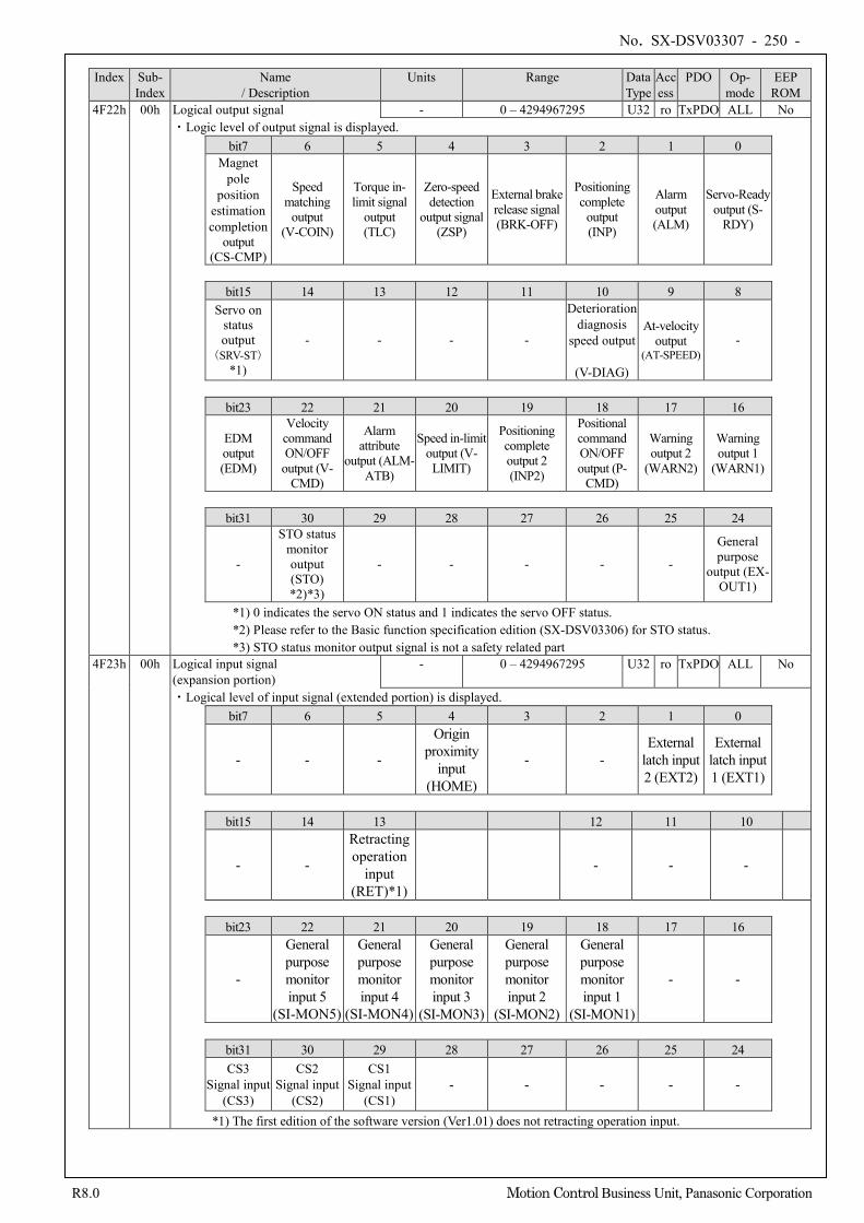
No. SX-DSV03307 - 250 -
R8.0 Motion Control Business Unit, Panasonic Corporation
Index Sub-
Index Name
/ Description Units Range Data
Type Access
PDO Op- mode
EEP ROM
4F22h 00h Logical output signal - 0 – 4294967295 U32 ro TxPDO ALL No ・Logic level of output signal is displayed.
bit7 6 5 4 3 2 1 0 Magnet
pole position
estimation completion
output (CS-CMP)
Speed matching
output (V-COIN)
Torque in-limit signal
output (TLC)
Zero-speed detection
output signal (ZSP)
External brake release signal (BRK-OFF)
Positioning complete
output (INP)
Alarm output (ALM)
Servo-Ready output (S-
RDY)
bit15 14 13 12 11 10 9 8
Servo on status output
(SRV-ST) *1)
- - - -
Deterioration diagnosis
speed output
(V-DIAG)
At-velocity output
(AT-SPEED) -
bit23 22 21 20 19 18 17 16
EDM output (EDM)
Velocity command ON/OFF
output (V-CMD)
Alarm attribute
output (ALM-ATB)
Speed in-limit output (V-LIMIT)
Positioning complete output 2 (INP2)
Positional command ON/OFF output (P-
CMD)
Warning output 2
(WARN2)
Warning output 1
(WARN1)
bit31 30 29 28 27 26 25 24
-
STO status monitor output (STO) *2)*3)
- - - - -
General purpose
output (EX-OUT1)
*1) 0 indicates the servo ON status and 1 indicates the servo OFF status. *2) Please refer to the Basic function specification edition (SX-DSV03306) for STO status. *3) STO status monitor output signal is not a safety related part
4F23h 00h Logical input signal (expansion portion)
- 0 – 4294967295 U32 ro TxPDO ALL No
・Logical level of input signal (extended portion) is displayed. bit7 6 5 4 3 2 1 0
- - -
Origin proximity
input (HOME)
- - External
latch input 2 (EXT2)
External latch input 1 (EXT1)
bit15 14 13 12 11 10
- -
Retracting operation
input (RET)*1)
- - -
bit23 22 21 20 19 18 17 16
-
General purpose monitor input 5
(SI-MON5)
General purpose monitor input 4
(SI-MON4)
General purpose monitor input 3
(SI-MON3)
General purpose monitor input 2
(SI-MON2)
General purpose monitor input 1
(SI-MON1)
- -
bit31 30 29 28 27 26 25 24 CS3
Signal input (CS3)
CS2 Signal input
(CS2)
CS1 Signal input
(CS1) - - - -
-
*1) The first edition of the software version (Ver1.01) does not retracting operation input.
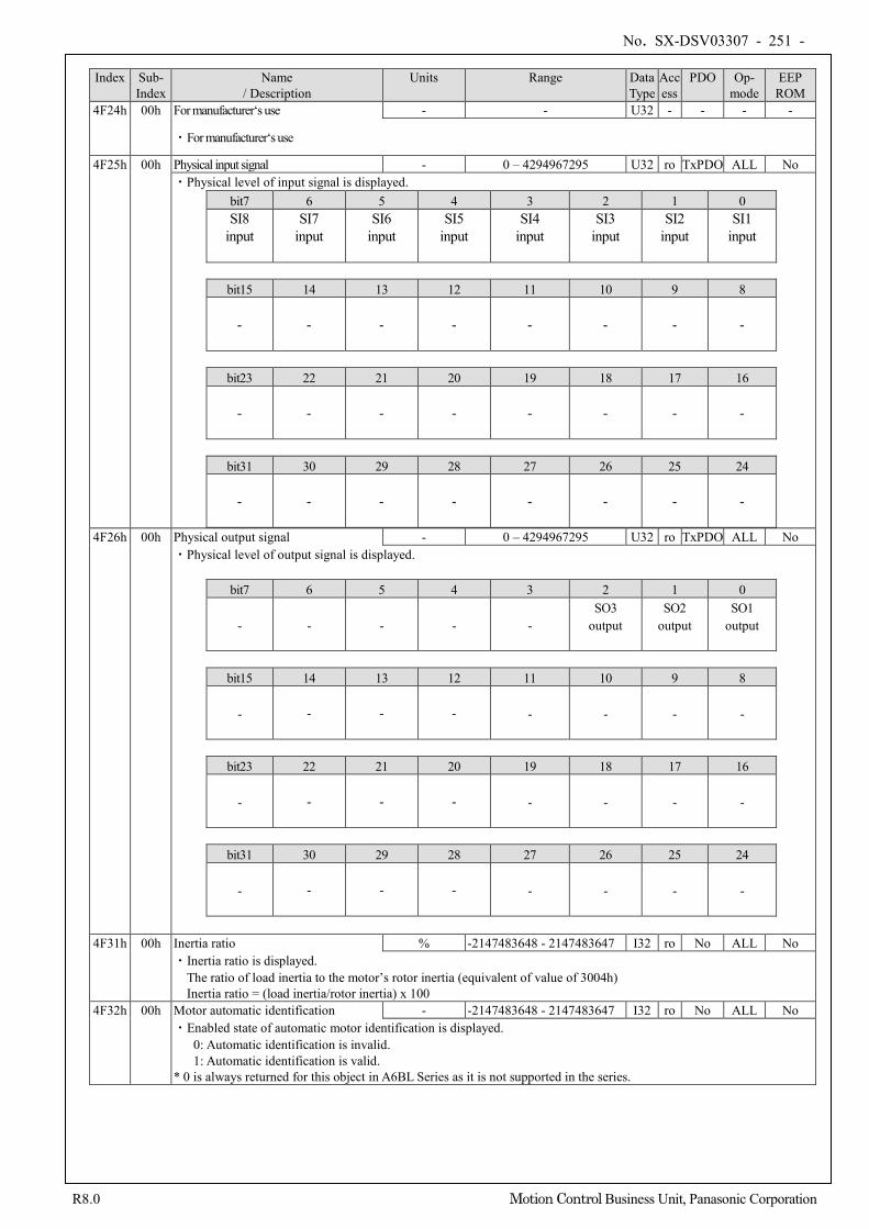
No. SX-DSV03307 - 251 -
R8.0 Motion Control Business Unit, Panasonic Corporation
Index Sub-
Index Name
/ Description Units Range Data
Type Access
PDO Op- mode
EEP ROM
4F24h 00h For manufacturer‘s use - - U32 - - - -
・For manufacturer‘s use
4F25h 00h Physical input signal - 0 – 4294967295 U32 ro TxPDO ALL No ・Physical level of input signal is displayed.
bit7 6 5 4 3 2 1 0 SI8
input
SI7 input
SI6 input
SI5 input
SI4 input
SI3 input
SI2 input
SI1 input
bit15 14 13 12 11 10 9 8
- - - - - - - -
bit23 22 21 20 19 18 17 16
- - - - - - - -
bit31 30 29 28 27 26 25 24
- - - - - - - -
4F26h 00h Physical output signal - 0 – 4294967295 U32 ro TxPDO ALL No ・Physical level of output signal is displayed.
bit7 6 5 4 3 2 1 0
- - - - - SO3
output
SO2 output
SO1 output
bit15 14 13 12 11 10 9 8
- - - - - - - -
bit23 22 21 20 19 18 17 16
- - - - - - - -
bit31 30 29 28 27 26 25 24
- - - - - - - -
4F31h 00h Inertia ratio % -2147483648 - 2147483647 I32 ro No ALL No
・Inertia ratio is displayed. The ratio of load inertia to the motor’s rotor inertia (equivalent of value of 3004h) Inertia ratio = (load inertia/rotor inertia) x 100
4F32h 00h Motor automatic identification - -2147483648 - 2147483647 I32 ro No ALL No ・Enabled state of automatic motor identification is displayed.
0: Automatic identification is invalid. 1: Automatic identification is valid.
* 0 is always returned for this object in A6BL Series as it is not supported in the series.
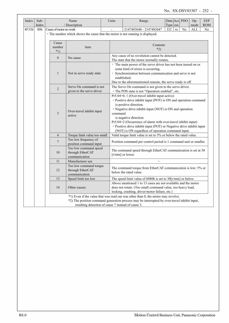
No. SX-DSV03307 - 252 -
R8.0 Motion Control Business Unit, Panasonic Corporation
Index Sub-
Index Name
/ Description Units Range Data
Type Access
PDO Op- mode
EEP ROM
4F33h 00h Cause of motor no work - -2147483648 - 2147483647 I32 ro No ALL No ・The number which shows the cause that the motor is not running is displayed.
Cause number
*1) item Contents
*2)
0 No cause Any cause of no revolution cannot be detected. The state that the motor normally rotates.
1 Not in servo ready state
・ The main power of the servo driver has not been turned on or some kind of errors is occurring.
・ Synchronization between communication and servo is not established.
Due to the aforementioned reasons, the servo ready is off.
2 Servo On command is not given to the servo driver
The Servo On command is not given to the servo driver. ・The PDS state is not “Operation enabled”, etc.
3 Over-travel inhibit input active
Pr5.04=0, 1 (Over-travel inhibit input active) ・Positive drive inhibit input (POT) is ON and operation command
is positive direction. ・Negative drive inhibit input (NOT) is ON and operation command
is negative direction. Pr5.04=2 (Occurrence of alarm with over-travel inhibit input) ・Positive drive inhibit input (POT) or Negative drive inhibit input
(NOT) is ON regardless of operation command input. 4 Torque limit value too small Valid torque limit value is set to 5% or below the rated value.
7 Too low frequency of position command input Position command per control period is 1 command unit or smaller.
10 Too low command speed through EtherCAT communication
The command speed through EtherCAT communication is set at 30 [r/min] or lower.
11 Manufacturer use -
12 Too low command torque through EtherCAT communication
The command torque from EtherCAT communication is low: 5% or below the rated value.
13 Speed limit too low The speed limit value of 6080h is set to 30[r/min] or below.
14 Other causes Above mentioned 1 to 13 cases are not available and the motor does not rotate. (Too small command value, too heavy load, locking, crashing, driver/motor failure, etc.)
*1) Even if the value that was read out was other than 0, the motor may revolve. *2) The position command generation process may be interrupted by over-travel inhibit input,
resulting detection of cause 7 instead of cause 3.
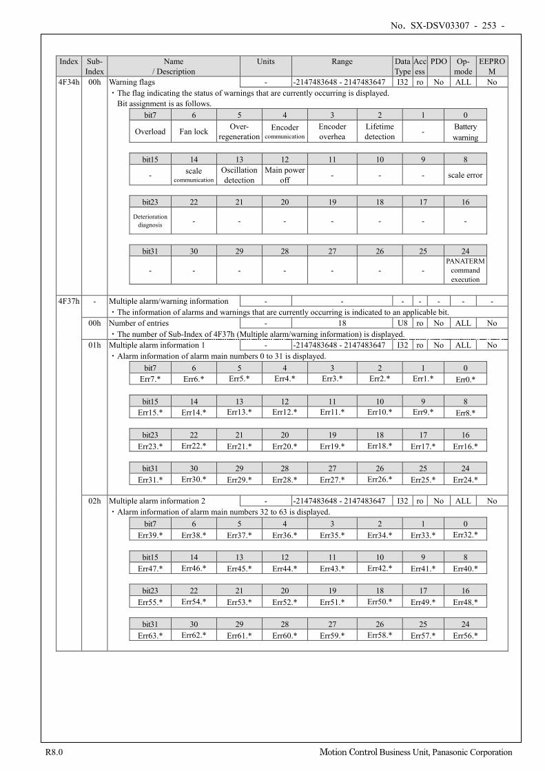
No. SX-DSV03307 - 253 -
R8.0 Motion Control Business Unit, Panasonic Corporation
Index Sub- Index
Name / Description
Units Range Data Type
Access
PDO Op- mode
EEPROM
4F34h 00h Warning flags - -2147483648 - 2147483647 I32 ro No ALL No ・The flag indicating the status of warnings that are currently occurring is displayed. Bit assignment is as follows.
bit7 6 5 4 3 2 1 0
Overload Fan lock Over- regeneration
Encoder communication
Encoder overhea
Lifetime detection - Battery
warning
bit15 14 13 12 11 10 9 8
- scale communication
Oscillation detection
Main power off - - - scale error
bit23 22 21 20 19 18 17 16
Deterioration diagnosis - - - - - - -
bit31 30 29 28 27 26 25 24
- - - - - - - PANATERM
command execution
4F37h - Multiple alarm/warning information - - - - - - -
・The information of alarms and warnings that are currently occurring is indicated to an applicable bit. 00h Number of entries - 18 U8 ro No ALL No
・The number of Sub-Index of 4F37h (Multiple alarm/warning information) is displayed. 01h Multiple alarm information 1 - -2147483648 - 2147483647 I32 ro No ALL No
・Alarm information of alarm main numbers 0 to 31 is displayed. bit7 6 5 4 3 2 1 0
Err7.* Err6.* Err5.* Err4.* Err3.* Err2.* Err1.* Err0.*
bit15 14 13 12 11 10 9 8 Err15.* Err14.* Err13.* Err12.* Err11.* Err10.* Err9.* Err8.*
bit23 22 21 20 19 18 17 16
Err23.* Err22.* Err21.* Err20.* Err19.* Err18.* Err17.* Err16.*
bit31 30 29 28 27 26 25 24 Err31.* Err30.* Err29.* Err28.* Err27.* Err26.* Err25.* Err24.*
02h Multiple alarm information 2 - -2147483648 - 2147483647 I32 ro No ALL No
・Alarm information of alarm main numbers 32 to 63 is displayed. bit7 6 5 4 3 2 1 0
Err39.* Err38.* Err37.* Err36.* Err35.* Err34.* Err33.* Err32.*
bit15 14 13 12 11 10 9 8 Err47.* Err46.* Err45.* Err44.* Err43.* Err42.* Err41.* Err40.*
bit23 22 21 20 19 18 17 16
Err55.* Err54.* Err53.* Err52.* Err51.* Err50.* Err49.* Err48.*
bit31 30 29 28 27 26 25 24 Err63.* Err62.* Err61.* Err60.* Err59.* Err58.* Err57.* Err56.*
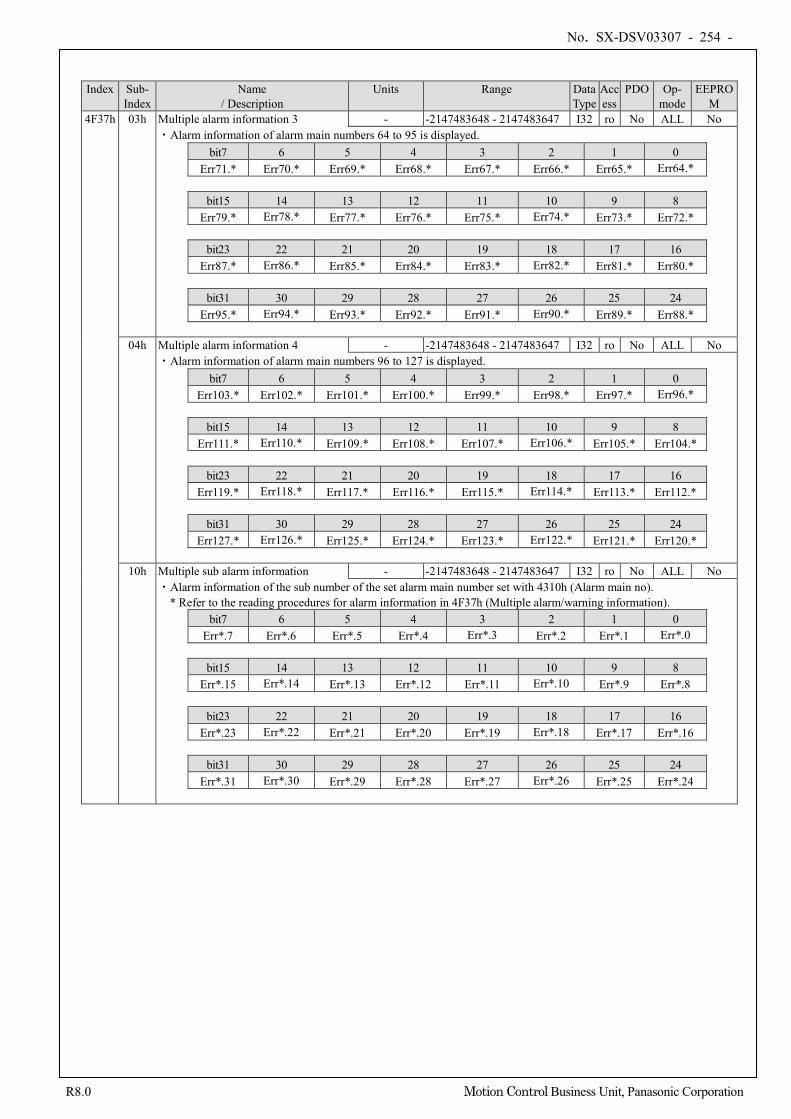
No. SX-DSV03307 - 254 -
R8.0 Motion Control Business Unit, Panasonic Corporation
Index Sub- Index
Name / Description
Units Range Data Type
Access
PDO Op- mode
EEPROM
4F37h 03h Multiple alarm information 3 - -2147483648 - 2147483647 I32 ro No ALL No ・Alarm information of alarm main numbers 64 to 95 is displayed.
bit7 6 5 4 3 2 1 0 Err71.* Err70.* Err69.* Err68.* Err67.* Err66.* Err65.* Err64.*
bit15 14 13 12 11 10 9 8
Err79.* Err78.* Err77.* Err76.* Err75.* Err74.* Err73.* Err72.*
bit23 22 21 20 19 18 17 16 Err87.* Err86.* Err85.* Err84.* Err83.* Err82.* Err81.* Err80.*
bit31 30 29 28 27 26 25 24
Err95.* Err94.* Err93.* Err92.* Err91.* Err90.* Err89.* Err88.*
04h Multiple alarm information 4 - -2147483648 - 2147483647 I32 ro No ALL No ・Alarm information of alarm main numbers 96 to 127 is displayed.
bit7 6 5 4 3 2 1 0 Err103.* Err102.* Err101.* Err100.* Err99.* Err98.* Err97.* Err96.*
bit15 14 13 12 11 10 9 8
Err111.* Err110.* Err109.* Err108.* Err107.* Err106.* Err105.* Err104.*
bit23 22 21 20 19 18 17 16 Err119.* Err118.* Err117.* Err116.* Err115.* Err114.* Err113.* Err112.*
bit31 30 29 28 27 26 25 24
Err127.* Err126.* Err125.* Err124.* Err123.* Err122.* Err121.* Err120.*
10h Multiple sub alarm information - -2147483648 - 2147483647 I32 ro No ALL No ・Alarm information of the sub number of the set alarm main number set with 4310h (Alarm main no).
* Refer to the reading procedures for alarm information in 4F37h (Multiple alarm/warning information). bit7 6 5 4 3 2 1 0
Err*.7 Err*.6 Err*.5 Err*.4 Err*.3 Err*.2 Err*.1 Err*.0
bit15 14 13 12 11 10 9 8 Err*.15 Err*.14 Err*.13 Err*.12 Err*.11 Err*.10 Err*.9 Err*.8
bit23 22 21 20 19 18 17 16
Err*.23 Err*.22 Err*.21 Err*.20 Err*.19 Err*.18 Err*.17 Err*.16
bit31 30 29 28 27 26 25 24 Err*.31 Err*.30 Err*.29 Err*.28 Err*.27 Err*.26 Err*.25 Err*.24
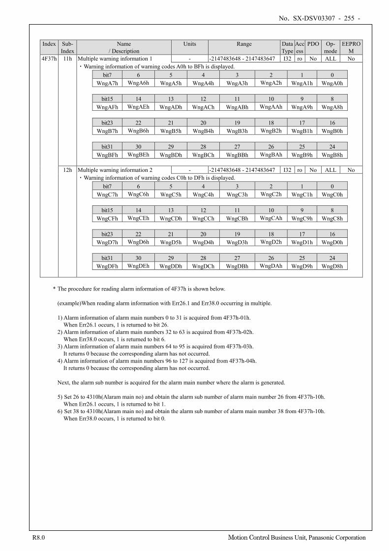
No. SX-DSV03307 - 255 -
R8.0 Motion Control Business Unit, Panasonic Corporation
Index Sub- Index
Name / Description
Units Range Data Type
Access
PDO Op- mode
EEPROM
4F37h 11h Multiple warning information 1 - -2147483648 - 2147483647 I32 ro No ALL No ・Warning information of warning codes A0h to BFh is displayed.
bit7 6 5 4 3 2 1 0 WngA7h WngA6h WngA5h WngA4h WngA3h WngA2h WngA1h WngA0h
bit15 14 13 12 11 10 9 8
WngAFh WngAEh WngADh WngACh WngABh WngAAh WngA9h WngA8h
bit23 22 21 20 19 18 17 16 WngB7h WngB6h WngB5h WngB4h WngB3h WngB2h WngB1h WngB0h
bit31 30 29 28 27 26 25 24
WngBFh WngBEh WngBDh WngBCh WngBBh WngBAh WngB9h WngB8h
12h Multiple warning information 2 - -2147483648 - 2147483647 I32 ro No ALL No ・Warning information of warning codes C0h to DFh is displayed.
bit7 6 5 4 3 2 1 0 WngC7h WngC6h WngC5h WngC4h WngC3h WngC2h WngC1h WngC0h
bit15 14 13 12 11 10 9 8
WngCFh WngCEh WngCDh WngCCh WngCBh WngCAh WngC9h WngC8h
bit23 22 21 20 19 18 17 16 WngD7h WngD6h WngD5h WngD4h WngD3h WngD2h WngD1h WngD0h
bit31 30 29 28 27 26 25 24
WngDFh WngDEh WngDDh WngDCh WngDBh WngDAh WngD9h WngD8h
* The procedure for reading alarm information of 4F37h is shown below.
(example)When reading alarm information with Err26.1 and Err38.0 occurring in multiple. 1) Alarm information of alarm main numbers 0 to 31 is acquired from 4F37h-01h. When Err26.1 occurs, 1 is returned to bit 26. 2) Alarm information of alarm main numbers 32 to 63 is acquired from 4F37h-02h. When Err38.0 occurs, 1 is returned to bit 6. 3) Alarm information of alarm main numbers 64 to 95 is acquired from 4F37h-03h. It returns 0 because the corresponding alarm has not occurred. 4) Alarm information of alarm main numbers 96 to 127 is acquired from 4F37h-04h. It returns 0 because the corresponding alarm has not occurred. Next, the alarm sub number is acquired for the alarm main number where the alarm is generated. 5) Set 26 to 4310h(Alaram main no) and obtain the alarm sub number of alarm main number 26 from 4F37h-10h. When Err26.1 occurs, 1 is returned to bit 1. 6) Set 38 to 4310h(Alaram main no) and obtain the alarm sub number of alarm main number 38 from 4F37h-10h. When Err38.0 occurs, 1 is returned to bit 0.
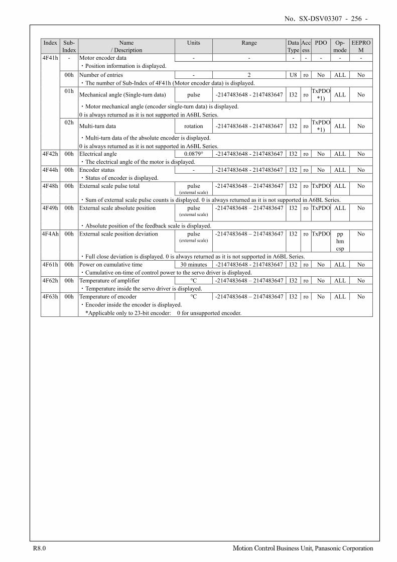
No. SX-DSV03307 - 256 -
R8.0 Motion Control Business Unit, Panasonic Corporation
Index Sub- Index
Name / Description
Units Range Data Type
Access
PDO Op- mode
EEPROM
4F41h - Motor encoder data - - - - - - - ・Position information is displayed.
00h Number of entries - 2 U8 ro No ALL No ・The number of Sub-Index of 4F41h (Motor encoder data) is displayed.
01h Mechanical angle (Single-turn data) pulse -2147483648 - 2147483647 I32 ro TxPDO *1) ALL No
・Motor mechanical angle (encoder single-turn data) is displayed. 0 is always returned as it is not supported in A6BL Series.
02h Multi-turn data rotation -2147483648 - 2147483647 I32 ro TxPDO *1) ALL No
・Multi-turn data of the absolute encoder is displayed. 0 is always returned as it is not supported in A6BL Series.
4F42h 00h Electrical angle 0.0879° -2147483648 - 2147483647 I32 ro No ALL No ・The electrical angle of the motor is displayed.
4F44h 00h Encoder status - -2147483648 - 2147483647 I32 ro No ALL No ・Status of encoder is displayed.
4F48h 00h External scale pulse total pulse (external scale)
-2147483648 – 2147483647 I32 ro TxPDO ALL No
・Sum of external scale pulse counts is displayed. 0 is always returned as it is not supported in A6BL Series. 4F49h 00h External scale absolute position pulse
(external scale) -2147483648 – 2147483647 I32 ro TxPDO ALL No
・Absolute position of the feedback scale is displayed. 4F4Ah 00h External scale position deviation pulse
(external scale) -2147483648 – 2147483647 I32 ro TxPDO pp
hm csp
No
・Full close deviation is displayed. 0 is always returned as it is not supported in A6BL Series. 4F61h 00h Power on cumulative time 30 minutes -2147483648 - 2147483647 I32 ro No ALL No
・Cumulative on-time of control power to the servo driver is displayed. 4F62h 00h Temperature of amplifier °C -2147483648 – 2147483647 I32 ro No ALL No
・Temperature inside the servo driver is displayed. 4F63h 00h Temperature of encoder °C -2147483648 – 2147483647 I32 ro No ALL No
・Encoder inside the encoder is displayed. *Applicable only to 23-bit encoder: 0 for unsupported encoder.
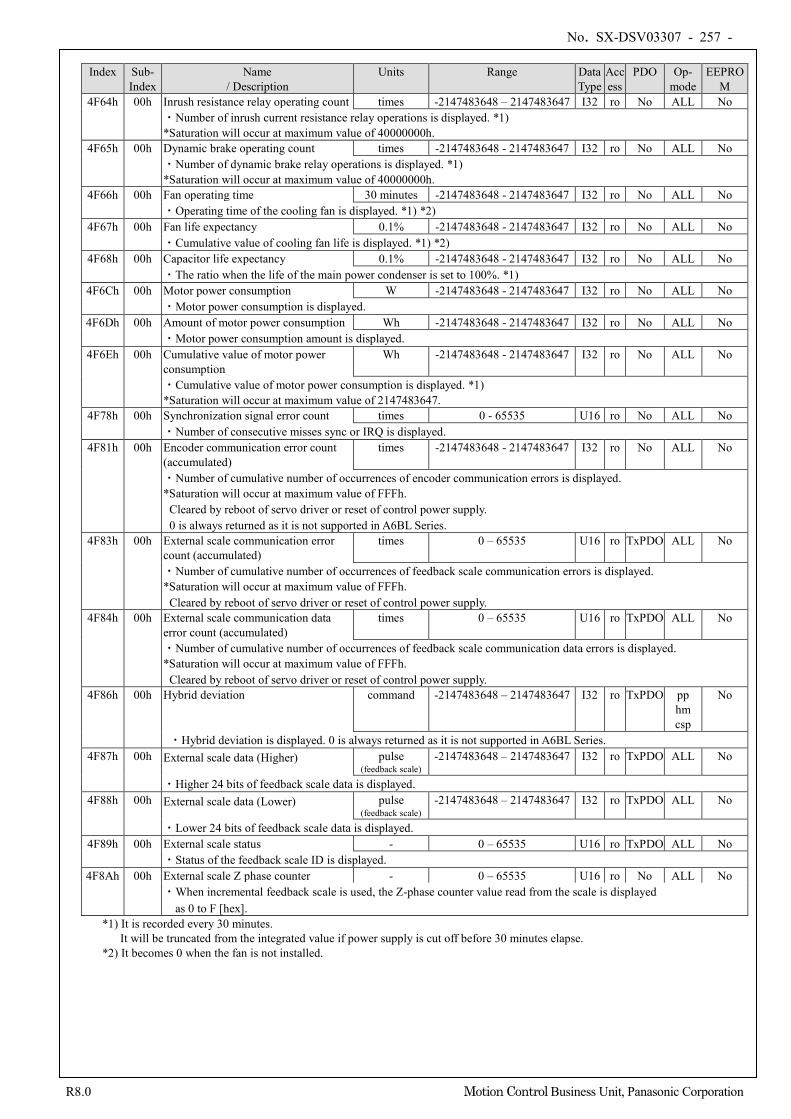
No. SX-DSV03307 - 257 -
R8.0 Motion Control Business Unit, Panasonic Corporation
Index Sub-
Index Name
/ Description Units Range Data
Type Access
PDO Op- mode
EEPROM
4F64h 00h Inrush resistance relay operating count times -2147483648 – 2147483647 I32 ro No ALL No ・Number of inrush current resistance relay operations is displayed. *1) *Saturation will occur at maximum value of 40000000h.
4F65h 00h Dynamic brake operating count times -2147483648 - 2147483647 I32 ro No ALL No ・Number of dynamic brake relay operations is displayed. *1) *Saturation will occur at maximum value of 40000000h.
4F66h 00h Fan operating time 30 minutes -2147483648 - 2147483647 I32 ro No ALL No ・Operating time of the cooling fan is displayed. *1) *2)
4F67h 00h Fan life expectancy 0.1% -2147483648 - 2147483647 I32 ro No ALL No ・Cumulative value of cooling fan life is displayed. *1) *2)
4F68h 00h Capacitor life expectancy 0.1% -2147483648 - 2147483647 I32 ro No ALL No ・The ratio when the life of the main power condenser is set to 100%. *1)
4F6Ch 00h Motor power consumption W -2147483648 - 2147483647 I32 ro No ALL No ・Motor power consumption is displayed.
4F6Dh 00h Amount of motor power consumption Wh -2147483648 - 2147483647 I32 ro No ALL No ・Motor power consumption amount is displayed.
4F6Eh 00h Cumulative value of motor power consumption
Wh -2147483648 - 2147483647 I32 ro No ALL No
・Cumulative value of motor power consumption is displayed. *1) *Saturation will occur at maximum value of 2147483647.
4F78h 00h Synchronization signal error count times 0 - 65535 U16 ro No ALL No ・Number of consecutive misses sync or IRQ is displayed.
4F81h 00h Encoder communication error count (accumulated)
times -2147483648 - 2147483647 I32 ro No ALL No
・Number of cumulative number of occurrences of encoder communication errors is displayed. *Saturation will occur at maximum value of FFFh.
Cleared by reboot of servo driver or reset of control power supply. 0 is always returned as it is not supported in A6BL Series.
4F83h 00h External scale communication error count (accumulated)
times 0 – 65535 U16 ro TxPDO ALL No
・Number of cumulative number of occurrences of feedback scale communication errors is displayed. *Saturation will occur at maximum value of FFFh.
Cleared by reboot of servo driver or reset of control power supply. 4F84h 00h External scale communication data
error count (accumulated) times 0 – 65535 U16 ro TxPDO ALL No
・Number of cumulative number of occurrences of feedback scale communication data errors is displayed. *Saturation will occur at maximum value of FFFh.
Cleared by reboot of servo driver or reset of control power supply. 4F86h 00h Hybrid deviation command -2147483648 – 2147483647 I32 ro TxPDO pp
hm csp
No
・Hybrid deviation is displayed. 0 is always returned as it is not supported in A6BL Series. 4F87h 00h External scale data (Higher) pulse
(feedback scale) -2147483648 – 2147483647 I32 ro TxPDO ALL No
・Higher 24 bits of feedback scale data is displayed. 4F88h 00h External scale data (Lower) pulse
(feedback scale) -2147483648 – 2147483647 I32 ro TxPDO ALL No
・Lower 24 bits of feedback scale data is displayed. 4F89h 00h External scale status - 0 – 65535 U16 ro TxPDO ALL No
・Status of the feedback scale ID is displayed. 4F8Ah 00h External scale Z phase counter - 0 – 65535 U16 ro No ALL No
・When incremental feedback scale is used, the Z-phase counter value read from the scale is displayed as 0 to F [hex].
*1) It is recorded every 30 minutes. It will be truncated from the integrated value if power supply is cut off before 30 minutes elapse.
*2) It becomes 0 when the fan is not installed.
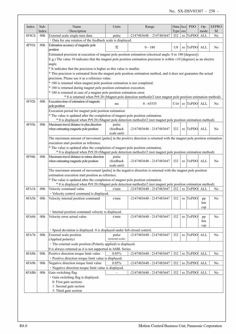
No. SX-DSV03307 - 258 -
R8.0 Motion Control Business Unit, Panasonic Corporation
Index Sub- Index
Name / Description
Units Range Data Type
Access
PDO Op- mode
EEPROM
4F8Ch 00h External scale single-turn data pulse -2147483648 – 2147483647 I32 ro TxPDO ALL No ・Data for one rotation of the feedback scale is displayed.
4F91h 00h Estimation accuracy of magnetic pole position 度 0 - 180 U8 ro TxPDO ALL No
Estimated precision at execution of magnet pole position estimation (electrical angle: 0 to 180 [degrees]) E.g.) The value 10 indicates that the magnet pole position estimation precision is within ±10 [degrees] as an electric angle. * It indicates that the precision is higher as this value is smaller. * This precision is estimated from the magnet pole position estimation method, and it does not guarantee the actual precision. Please use it as a reference value. * 180 is returned when magnet pole position estimation is not completed. * 180 is returned during magnet pole position estimation execution. * 180 is returned in case of a magnet pole position estimation error. * 0 is returned when Pr9.20 (Magnet pole detection method)≠2 (not magnet pole position estimation method).
4F92h 00h Execution time of estimation of magnetic pole position ms 0 - 65535 U16 ro TxPDO ALL No
Execution period for magnet pole position estimation * The value is updated after the completion of magnet pole position estimation.
* 0 is displayed when Pr9.20 (Magnet pole detection method)≠2 (not magnet pole position estimation method). 4F93h 00h Maximum travel distance to plus direction
when estimating magnetic pole position pulse
(feedback scale unit)
-2147483648 - 2147483647 I32 ro TxPDO ALL No
The maximum amount of movement [pulse] in the positive direction is returned with the magnet pole position estimation execution start position as reference. * The value is updated after the completion of magnet pole position estimation.
* 0 is displayed when Pr9.20 (Magnet pole detection method)≠2 (not magnet pole position estimation method). 4F94h 00h Maximum travel distance to minus direction
when estimating magnetic pole position pulse
(feedback scale unit)
-2147483648 - 2147483647 I32 ro TxPDO ALL No
The maximum amount of movement [pulse] in the negative direction is returned with the magnet pole position estimation execution start position as reference. * The value is updated after the completion of magnet pole position estimation.
* 0 is displayed when Pr9.20 (Magnet pole detection method)≠2 (not magnet pole position estimation method). 4FA1h 00h Velocity command value r/min -2147483648 - 2147483647 I32 ro TxPDO ALL No
・Velocity control command is displayed. 4FA5h 00h Velocity internal position command r/min -2147483648 - 2147483647 I32 ro TxPDO pp
hm csp
No
・Internal position command velocity is displayed. 4FA6h 00h Velocity error actual value r/min -2147483648 - 2147483647 I32 ro TxPDO pp
hm csp
No
・Speed deviation is displayed. 0 is displayed under full-closed control. 4FA7h 00h External scale position
(Applied polarity) pulse
(external scale) -2147483648 - 2147483647 I32 ro TxPDO ALL No
・The external scale position (Polarity applied) is displayed. 0 is always returned as it is not supported in A6BL Series.
4FA8h 00h Positive direction torque limit value 0.05% -2147483648 - 2147483647 I32 ro TxPDO ALL No ・Positive direction torque limit value is displayed.
4FA9h 00h Negative direction torque limit value 0.05% -2147483648 - 2147483647 I32 ro TxPDO ALL No ・Negative direction torque limit value is displayed.
4FABh 00h Gain switching flag - -2147483648 - 2147483647 I32 ro TxPDO ALL No ・Gain switching flag is displayed.
0: First gain sectionz 1: Second gain section 3: Third gain section
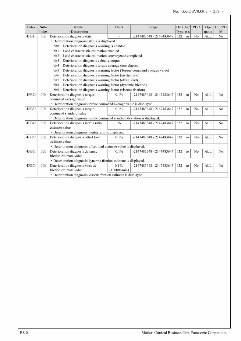
No. SX-DSV03307 - 259 -
R8.0 Motion Control Business Unit, Panasonic Corporation
Index Sub- Index
Name / Description
Units Range Data Type
Access
PDO Op- mode
EEPROM
4FB1h 00h Deterioration diagnosis state - -2147483648 - 2147483647 I32 ro No ALL No ・Deterioration diagnosis status is displayed. bit0:Deterioration diagnosis warning is enabled bit1:Load characteristic estimation enabled bit2:Load characteristic estimation convergence completed bit3:Deterioration diagnosis velocity output bit4:Deterioration diagnosis torque average time elapsed
bit5:Deterioration diagnosis warning factor (Torque command average value) bit6:Deterioration diagnosis warning factor (inertia ratio) bit7:Deterioration diagnosis warning factor (offset load) bit8:Deterioration diagnosis warning factor (dynamic friction) bit9:Deterioration diagnosis warning factor (viscous friction)
4FB2h 00h Deterioration diagnosis torque command average value
0.1% -2147483648 - 2147483647 I32 ro No ALL No
・Deterioration diagnosis torque command average value is displayed. 4FB3h 00h Deterioration diagnosis torque
command standard value 0.1% -2147483648 - 2147483647 I32 ro No ALL No
・Deterioration diagnosis torque command standard deviation is displayed. 4FB4h 00h Deterioration diagnosis inertia ratio
estimate value % -2147483648 - 2147483647 I32 ro No ALL No
・Deterioration diagnosis inertia ratio is displayed. 4FB5h 00h Deterioration diagnosis offset load
estimate value 0.1% -2147483648 - 2147483647 I32 ro No ALL No
・Deterioration diagnosis offset load estimate value is displayed. 4FB6h 00h Deterioration diagnosis dynamic
friction estimate value 0.1% -2147483648 - 2147483647 I32 ro No ALL No
・Deterioration diagnosis dynamic friction estimate is displayed. 4FB7h 00h Deterioration diagnosis viscous
friction estimate value 0.1%/
(10000r/min) -2147483648 - 2147483647 I32 ro No ALL No
・Deterioration diagnosis viscous friction estimate is displayed.
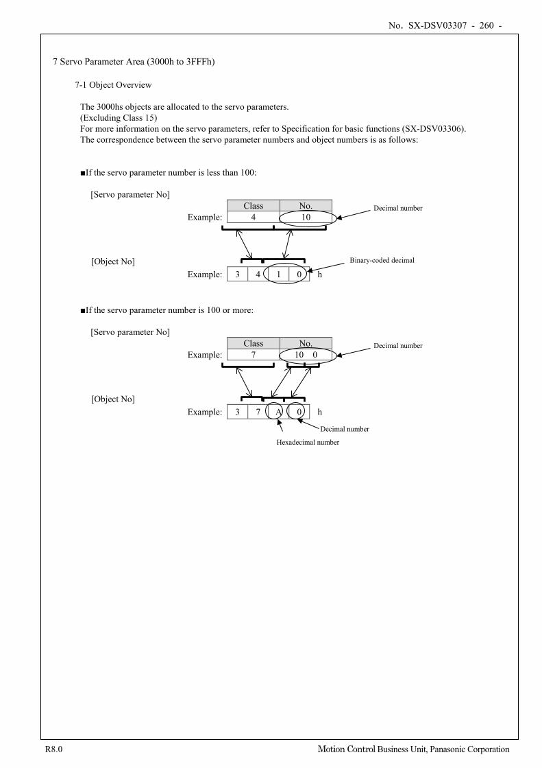
No. SX-DSV03307 - 260 -
R8.0 Motion Control Business Unit, Panasonic Corporation
7 Servo Parameter Area (3000h to 3FFFh)
7-1 Object Overview
The 3000hs objects are allocated to the servo parameters. (Excluding Class 15) For more information on the servo parameters, refer to Specification for basic functions (SX-DSV03306). The correspondence between the servo parameter numbers and object numbers is as follows:
■If the servo parameter number is less than 100:
[Servo parameter No] Class No.
Example: 4 10
[Object No] Example: 3 4 1 0 h
■If the servo parameter number is 100 or more:
[Servo parameter No] Class No.
Example: 7 10 0
[Object No] Example: 3 7 A 0 h
Decimal number
Binary-coded decimal
Decimal number
Decimal number
Hexadecimal number
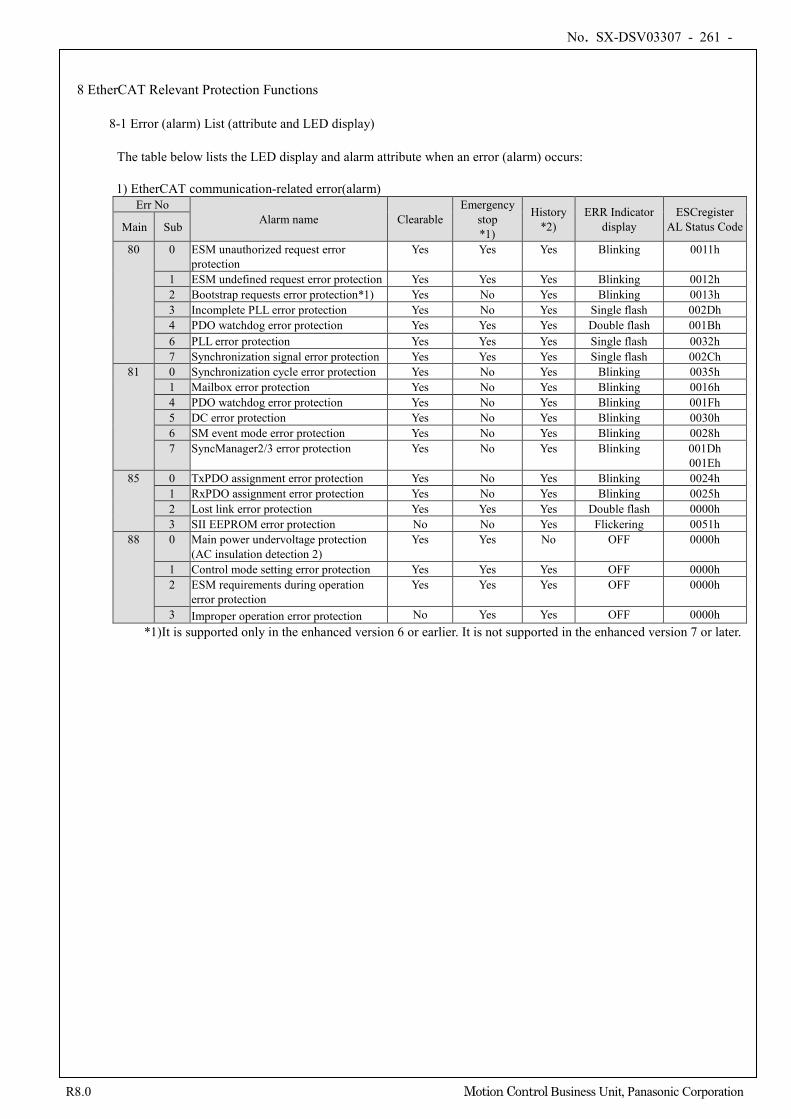
No. SX-DSV03307 - 261 -
R8.0 Motion Control Business Unit, Panasonic Corporation
8 EtherCAT Relevant Protection Functions
8-1 Error (alarm) List (attribute and LED display) The table below lists the LED display and alarm attribute when an error (alarm) occurs: 1) EtherCAT communication-related error(alarm)
Err No Alarm name Clearable
Emergency stop *1)
History *2)
ERR Indicator display
ESCregister AL Status Code Main Sub
80 0 ESM unauthorized request error protection
Yes Yes Yes Blinking 0011h
1 ESM undefined request error protection Yes Yes Yes Blinking 0012h 2 Bootstrap requests error protection*1) Yes No Yes Blinking 0013h 3 Incomplete PLL error protection Yes No Yes Single flash 002Dh 4 PDO watchdog error protection Yes Yes Yes Double flash 001Bh 6 PLL error protection Yes Yes Yes Single flash 0032h 7 Synchronization signal error protection Yes Yes Yes Single flash 002Ch
81 0 Synchronization cycle error protection Yes No Yes Blinking 0035h 1 Mailbox error protection Yes No Yes Blinking 0016h 4 PDO watchdog error protection Yes No Yes Blinking 001Fh 5 DC error protection Yes No Yes Blinking 0030h 6 SM event mode error protection Yes No Yes Blinking 0028h 7 SyncManager2/3 error protection Yes No Yes Blinking 001Dh
001Eh 85 0 TxPDO assignment error protection Yes No Yes Blinking 0024h
1 RxPDO assignment error protection Yes No Yes Blinking 0025h 2 Lost link error protection Yes Yes Yes Double flash 0000h 3 SII EEPROM error protection No No Yes Flickering 0051h
88 0 Main power undervoltage protection (AC insulation detection 2)
Yes Yes No OFF 0000h
1 Control mode setting error protection Yes Yes Yes OFF 0000h 2 ESM requirements during operation
error protection Yes Yes Yes OFF 0000h
3 Improper operation error protection No Yes Yes OFF 0000h *1)It is supported only in the enhanced version 6 or earlier. It is not supported in the enhanced version 7 or later.
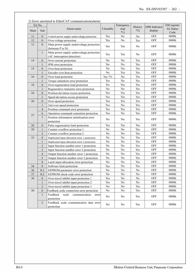
No. SX-DSV03307 - 262 -
R8.0 Motion Control Business Unit, Panasonic Corporation
2) Error unrelated to EtherCAT communication(alarm) Err No
Alarm name Clearable Emergency
stop *1)
History *2)
ERR Indicator display
ESCregister AL Status
Code Main Sub
11 0 Control power supply undervoltage protection Yes No No OFF 0000h 12 0 Over-voltage protection Yes No Yes OFF 0000h 13 0 Main power supply undervoltage protection
(between P to N) Yes Yes No OFF 0000h
1 Main power supply undervoltage protection (AC interception detection)
Yes Yes No OFF 0000h
14 0 Over-current protection No No Yes OFF 0000h 1 IPM error protection No No Yes OFF 0000h
15 0 Over-heat protection No Yes Yes OFF 0000h 1 Encoder over-heat protection No Yes Yes OFF 0000h
16 0 Over-load protection Yes *3) No Yes OFF 0000h 1 Torque saturation error protection Yes No Yes OFF 0000h
18 0 Over-regeneration load protection No Yes Yes OFF 0000h 1 Regenerative transistor error protection No No Yes OFF 0000h
24 0 Position deviation excess protection Yes Yes Yes OFF 0000h 1 Speed deviation excess protection Yes Yes Yes OFF 0000h
26 0 Over-speed protection Yes Yes Yes OFF 0000h 1 2nd over-speed protection Yes No Yes OFF 0000h
27
4 Position command error protection Yes Yes Yes OFF 0000h 6 Operation command contention protection Yes No Yes OFF 0000h 7 Position information initialization error
protection No No Yes OFF 0000h
28 0 Pulse regeneration limit protection Yes Yes Yes OFF 0000h 29 1 Counter overflow protection 1 No No Yes OFF 0000h
2 Counter overflow protection 2 No No Yes OFF 0000h 33 0 Duplicated input allocation error 1 protection No No Yes OFF 0000h
1 Duplicated input allocation error 2 protection No No Yes OFF 0000h 2 Input function number error 1 protection No No Yes OFF 0000h 3 Input function number error 2 protection No No Yes OFF 0000h 4 Output function number error 1 protection No No Yes OFF 0000h 5 Output function number error 2 protection No No Yes OFF 0000h 8 Latch input allocation error protection No No Yes OFF 0000h
34 0 Software limit protection Yes No Yes OFF 0000h 36 0-1 EEPROM parameter error protection No No No OFF 0000h 37 0-2 EEPROM check code error protection No No No OFF 0000h 38 0 Over-travel inhibit input protection 1 Yes No No OFF 0000h
1 Over-travel inhibit input protection 2 Yes No No OFF 0000h 2 Over-travel inhibit input protection 3 No No Yes OFF 0000h
50 0 Feedback scale connection error protection No No Yes OFF 0000h 1 Feedback scale communication error
protection No No Yes OFF 0000h
2 Feedback scale communication data error protection
No No Yes OFF 0000h
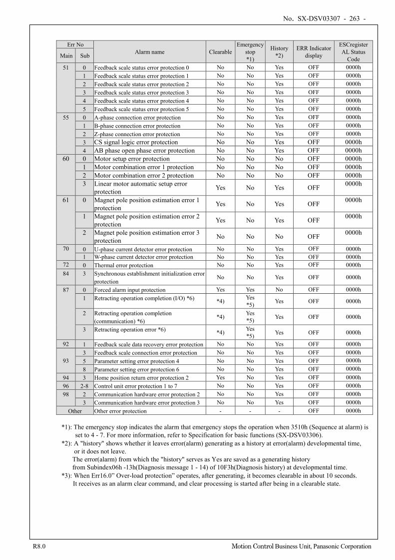
No. SX-DSV03307 - 263 -
R8.0 Motion Control Business Unit, Panasonic Corporation
Err No Alarm name Clearable
Emergency stop *1)
History *2)
ERR Indicator display
ESCregister AL Status
Code Main Sub
51 0 Feedback scale status error protection 0 No No Yes OFF 0000h 1 Feedback scale status error protection 1 No No Yes OFF 0000h 2 Feedback scale status error protection 2 No No Yes OFF 0000h 3 Feedback scale status error protection 3 No No Yes OFF 0000h 4 Feedback scale status error protection 4 No No Yes OFF 0000h 5 Feedback scale status error protection 5 No No Yes OFF 0000h
55 0 A-phase connection error protection No No Yes OFF 0000h 1 B-phase connection error protection No No Yes OFF 0000h 2 Z-phase connection error protection No No Yes OFF 0000h 3 CS signal logic error protection No No Yes OFF 0000h 4 AB phase open phase error protection No No Yes OFF 0000h
60 0 Motor setup error protection No No No OFF 0000h 1 Motor combination error 1 protection No No No OFF 0000h 2 Motor combination error 2 protection No No No OFF 0000h 3 Linear motor automatic setup error
protection Yes No Yes OFF 0000h
61 0 Magnet pole position estimation error 1 protection Yes No Yes OFF 0000h
1 Magnet pole position estimation error 2 protection Yes No Yes OFF 0000h
2 Magnet pole position estimation error 3 protection No No No OFF 0000h
70 0 U-phase current detector error protection No No Yes OFF 0000h 1 W-phase current detector error protection No No Yes OFF 0000h
72 0 Thermal error protection No No Yes OFF 0000h 84 3 Synchronous establishment initialization error
protection No No Yes OFF 0000h
87 0 Forced alarm input protection Yes Yes No OFF 0000h 1 Retracting operation completion (I/O) *6) *4) Yes
*5) Yes OFF 0000h
2 Retracting operation completion (communication) *6)
*4) Yes *5) Yes OFF 0000h
3 Retracting operation error *6) *4) Yes *5) Yes OFF 0000h
92 1 Feedback scale data recovery error protection No No Yes OFF 0000h
93 3 Feedback scale connection error protection No No Yes OFF 0000h 5 Parameter setting error protection 4 No No Yes OFF 0000h 8 Parameter setting error protection 6 No No Yes OFF 0000h
94 3 Home position return error protection 2 Yes No Yes OFF 0000h 96 2-8 Control unit error protection 1 to 7 No No Yes OFF 0000h 98 2 Communication hardware error protection 2 No No Yes OFF 0000h
3 Communication hardware error protection 3 No No Yes OFF 0000h Other Other error protection - - - OFF 0000h
*1): The emergency stop indicates the alarm that emergency stops the operation when 3510h (Sequence at alarm) is
set to 4 - 7. For more information, refer to Specification for basic functions (SX-DSV03306). *2): A "history" shows whether it leaves error(alarm) generating as a history at error(alarm) developmental time,
or it does not leave. The error(alarm) from which the "history" serves as Yes are saved as a generating history from Subindex06h -13h(Diagnosis message 1 - 14) of 10F3h(Diagnosis history) at developmental time.
*3): When Err16.0” Over-load protection” operates, after generating, it becomes clearable in about 10 seconds. It receives as an alarm clear command, and clear processing is started after being in a clearable state.
No. SX-DSV03307 - 264 -
R8.0 Motion Control Business Unit, Panasonic Corporation
*4) Whether error clear is valid or not is switched depending on the settings in 3668h8 bit0-2. bit0: Alarm clear attribute in Err87.1 (Retreat operation completion (I/O)) bit1: Alarm clear attribute in Err87.2 (Retreat operation completion (communication)) bit2: Alarm clear attribute in Err87.3 (Retreat operation error) For any of these, 0: Alarm clear invalid, 1: Alarm clear valid
*5) While the attribute says it is an alarm supporting immediate stop, it will have an operation by retreat operation function regardless of Pr5.10 “Sequence at alarm,” with the alarm occurring at completion of the retreat operation when the retreat operation startup condition is established. For details about retreat operation function, please refer to Chapters 6-9 in Basic function volume of the Technical document (SX-DSV03306). It behaves as an alarm supporting immediate stop after retreat operation completion, including the fall prevention function during alarm occurrence. For fall prevention function during alarm occurrence, please refer to Section 6-3-6-1 in Basic function volume of the Technical document (SX-DSV03306).
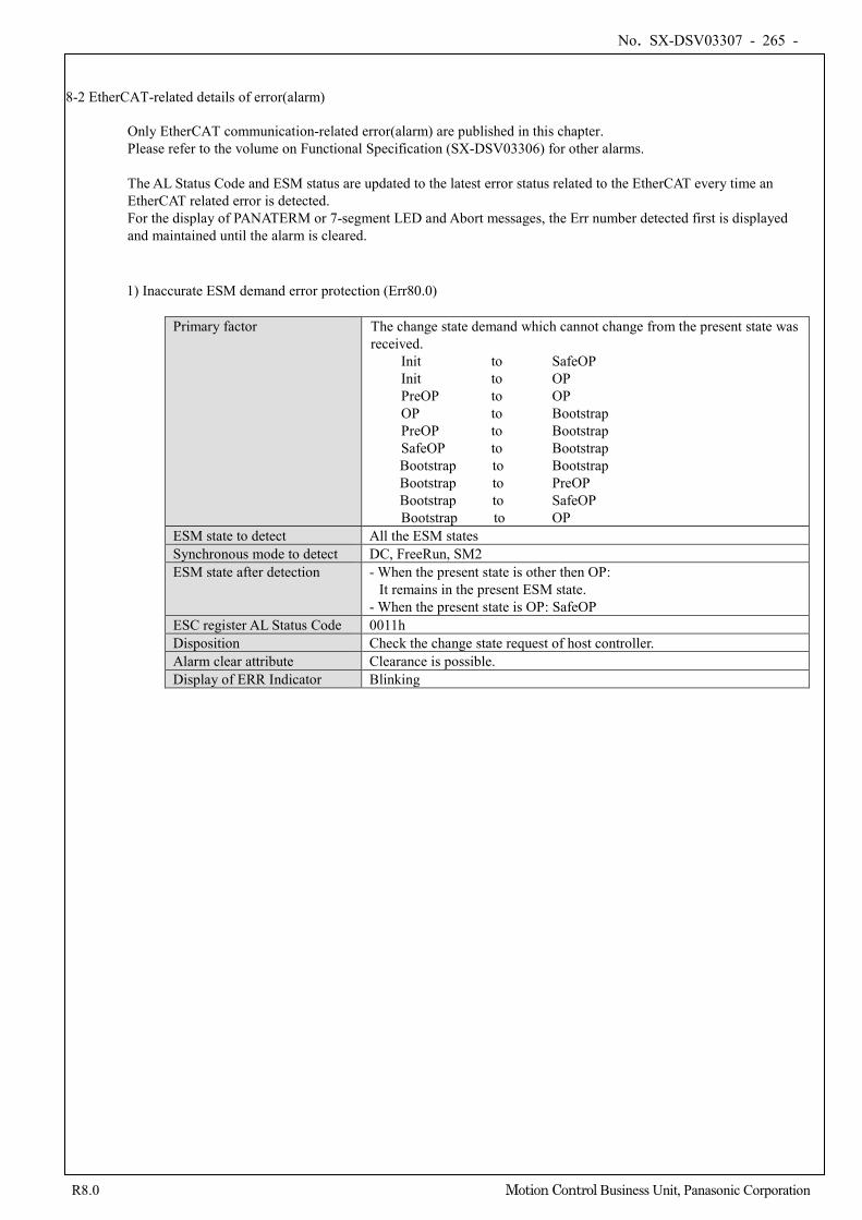
No. SX-DSV03307 - 265 -
R8.0 Motion Control Business Unit, Panasonic Corporation
8-2 EtherCAT-related details of error(alarm)
Only EtherCAT communication-related error(alarm) are published in this chapter. Please refer to the volume on Functional Specification (SX-DSV03306) for other alarms. The AL Status Code and ESM status are updated to the latest error status related to the EtherCAT every time an EtherCAT related error is detected. For the display of PANATERM or 7-segment LED and Abort messages, the Err number detected first is displayed and maintained until the alarm is cleared.
1) Inaccurate ESM demand error protection (Err80.0)
Primary factor The change state demand which cannot change from the present state was received.
Init to SafeOP Init to OP PreOP to OP OP to Bootstrap PreOP to Bootstrap SafeOP to Bootstrap Bootstrap to Bootstrap
Bootstrap to PreOP Bootstrap to SafeOP
Bootstrap to OP ESM state to detect All the ESM states Synchronous mode to detect DC, FreeRun, SM2 ESM state after detection - When the present state is other then OP:
It remains in the present ESM state. - When the present state is OP: SafeOP
ESC register AL Status Code 0011h Disposition Check the change state request of host controller. Alarm clear attribute Clearance is possible. Display of ERR Indicator Blinking
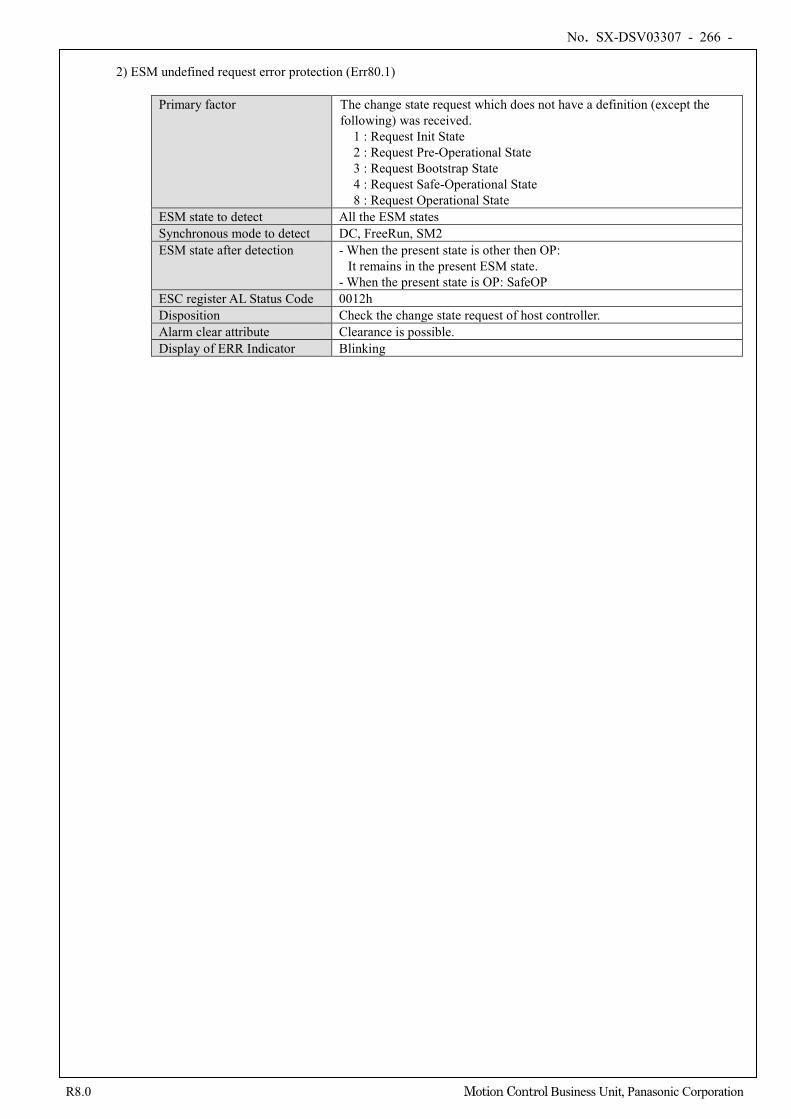
No. SX-DSV03307 - 266 -
R8.0 Motion Control Business Unit, Panasonic Corporation
2) ESM undefined request error protection (Err80.1)
Primary factor The change state request which does not have a definition (except the following) was received. 1 : Request Init State 2 : Request Pre-Operational State 3 : Request Bootstrap State 4 : Request Safe-Operational State 8 : Request Operational State
ESM state to detect All the ESM states Synchronous mode to detect DC, FreeRun, SM2 ESM state after detection - When the present state is other then OP:
It remains in the present ESM state. - When the present state is OP: SafeOP
ESC register AL Status Code 0012h Disposition Check the change state request of host controller. Alarm clear attribute Clearance is possible. Display of ERR Indicator Blinking
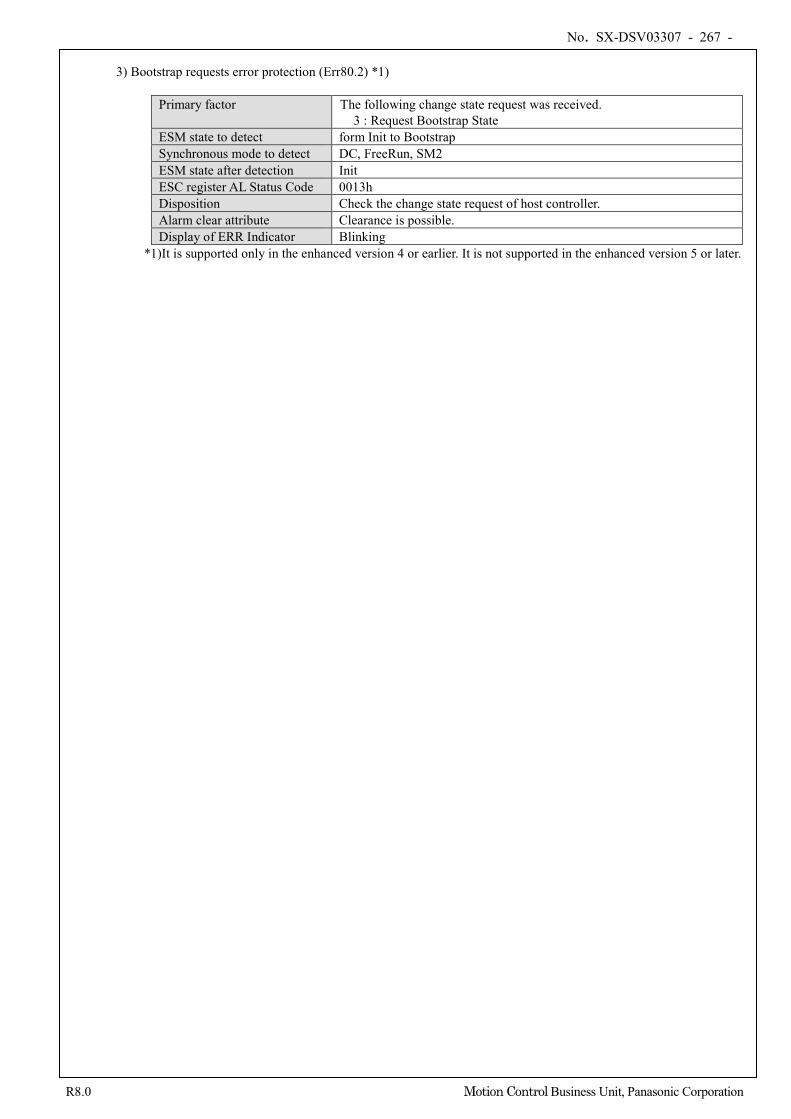
No. SX-DSV03307 - 267 -
R8.0 Motion Control Business Unit, Panasonic Corporation
3) Bootstrap requests error protection (Err80.2) *1)
Primary factor The following change state request was received. 3 : Request Bootstrap State
ESM state to detect form Init to Bootstrap Synchronous mode to detect DC, FreeRun, SM2 ESM state after detection Init ESC register AL Status Code 0013h Disposition Check the change state request of host controller. Alarm clear attribute Clearance is possible. Display of ERR Indicator Blinking
*1)It is supported only in the enhanced version 4 or earlier. It is not supported in the enhanced version 5 or later.
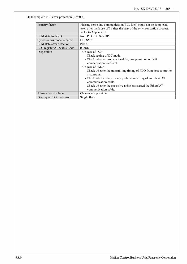
No. SX-DSV03307 - 268 -
R8.0 Motion Control Business Unit, Panasonic Corporation
4) Incomplete PLL error protection (Err80.3)
Primary factor Phasing servo and communication(PLL lock) could not be completed even after the lapse of 1s after the start of the synchronization process. Refer to Appendix 1.
ESM state to detect from PreOP to SafeOP Synchronous mode to detect DC, SM2 ESM state after detection PreOP ESC register AL Status Code 002Dh Disposition <In case of DC>
- Check setting of DC mode. - Check whether propagation delay compensation or drift
compensation is correct. <In case of SM2>
- Check whether the transmitting timing of PDO from host controller is constant.
- Check whether there is any problem in wiring of an EtherCAT communication cable.
- Check whether the excessive noise has started the EtherCAT communication cable.
Alarm clear attribute Clearance is possible. Display of ERR Indicator Single flash
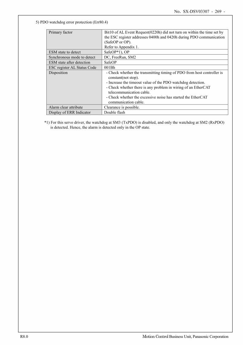
No. SX-DSV03307 - 269 -
R8.0 Motion Control Business Unit, Panasonic Corporation
5) PDO watchdog error protection (Err80.4)
Primary factor Bit10 of AL Event Request(0220h) did not turn on within the time set by the ESC register addresses 0400h and 0420h during PDO communication (SafeOP or OP). Refer to Appendix 1.
ESM state to detect SafeOP*1), OP Synchronous mode to detect DC, FreeRun, SM2 ESM state after detection SafeOP ESC register AL Status Code 001Bh Disposition - Check whether the transmitting timing of PDO from host controller is
constant(not stop). - Increase the timeout value of the PDO watchdog detection. - Check whether there is any problem in wiring of an EtherCAT
telecommunication cable. - Check whether the excessive noise has started the EtherCAT
communication cable. Alarm clear attribute Clearance is possible. Display of ERR Indicator Double flash
*1) For this servo driver, the watchdog at SM3 (TxPDO) is disabled, and only the watchdog at SM2 (RxPDO)
is detected. Hence, the alarm is detected only in the OP state.
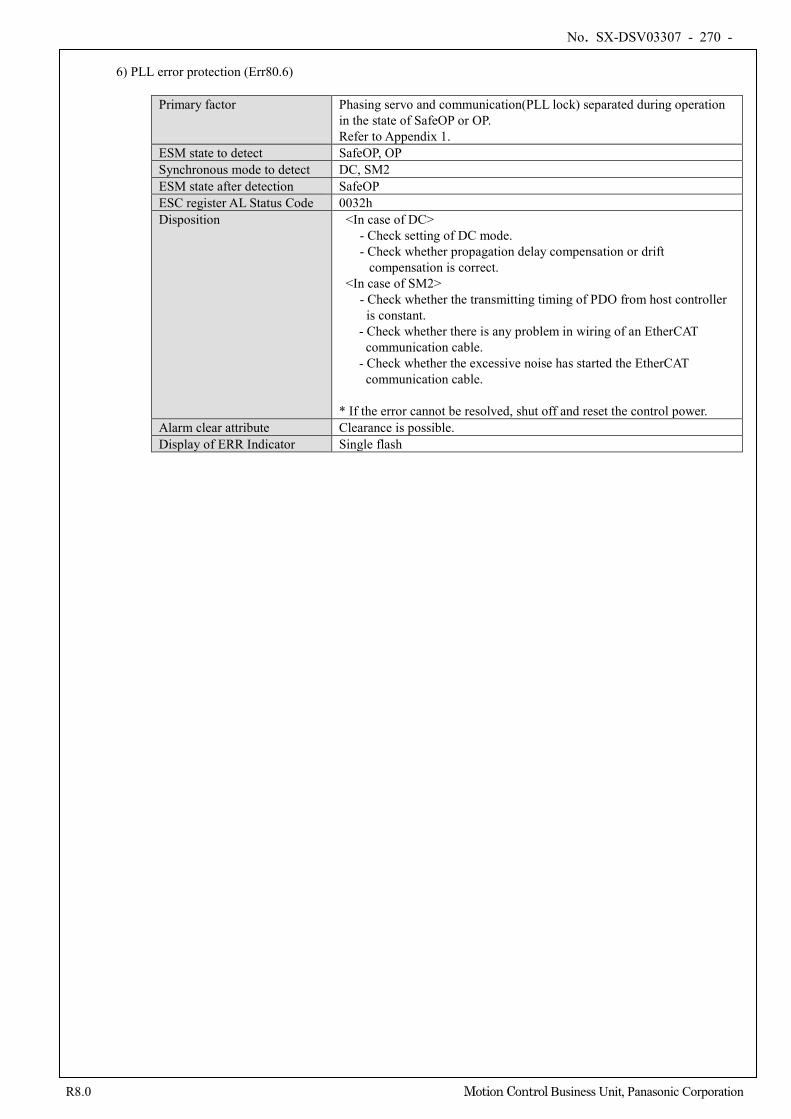
No. SX-DSV03307 - 270 -
R8.0 Motion Control Business Unit, Panasonic Corporation
6) PLL error protection (Err80.6)
Primary factor Phasing servo and communication(PLL lock) separated during operation in the state of SafeOP or OP. Refer to Appendix 1.
ESM state to detect SafeOP, OP Synchronous mode to detect DC, SM2 ESM state after detection SafeOP ESC register AL Status Code 0032h Disposition <In case of DC>
- Check setting of DC mode. - Check whether propagation delay compensation or drift
compensation is correct. <In case of SM2>
- Check whether the transmitting timing of PDO from host controller is constant.
- Check whether there is any problem in wiring of an EtherCAT communication cable.
- Check whether the excessive noise has started the EtherCAT communication cable.
* If the error cannot be resolved, shut off and reset the control power.
Alarm clear attribute Clearance is possible. Display of ERR Indicator Single flash
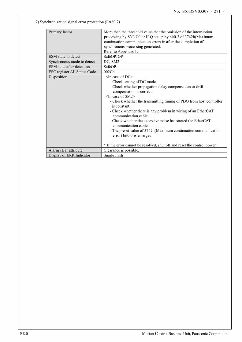
No. SX-DSV03307 - 271 -
R8.0 Motion Control Business Unit, Panasonic Corporation
7) Synchronization signal error protection (Err80.7)
Primary factor More than the threshold value that the omission of the interruption processing by SYNC0 or IRQ set up by bit0-3 of 3742h(Maximum continuation communication error) in after the completion of synchronous processing generated. Refer to Appendix 1.
ESM state to detect SafeOP, OP Synchronous mode to detect DC, SM2 ESM state after detection SafeOP ESC register AL Status Code 002Ch Disposition <In case of DC>
- Check setting of DC mode. - Check whether propagation delay compensation or drift
compensation is correct. <In case of SM2>
- Check whether the transmitting timing of PDO from host controller is constant.
- Check whether there is any problem in wiring of an EtherCAT communication cable.
- Check whether the excessive noise has started the EtherCAT communication cable.
- The preset value of 3742h(Maximum continuation communication error) bit0-3 is enlarged.
* If the error cannot be resolved, shut off and reset the control power.
Alarm clear attribute Clearance is possible. Display of ERR Indicator Single flash
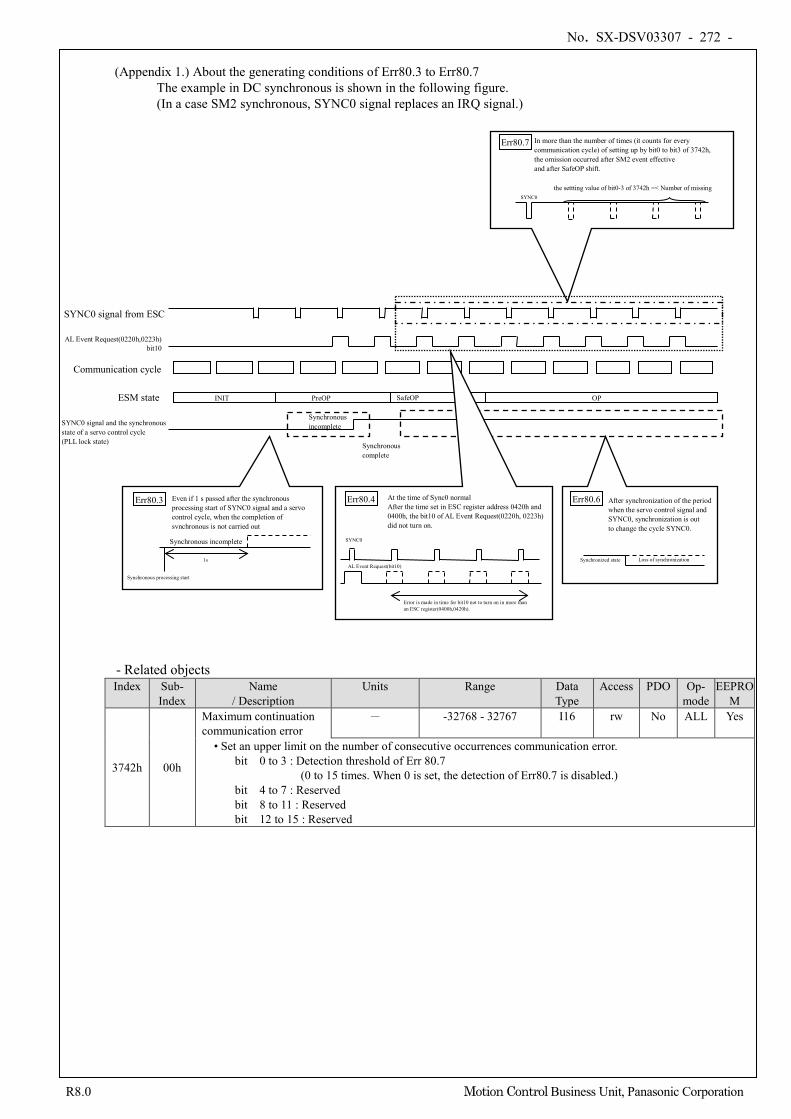
No. SX-DSV03307 - 272 -
R8.0 Motion Control Business Unit, Panasonic Corporation
(Appendix 1.) About the generating conditions of Err80.3 to Err80.7
The example in DC synchronous is shown in the following figure. (In a case SM2 synchronous, SYNC0 signal replaces an IRQ signal.)
- Related objects Index Sub-
Index Name
/ Description Units Range Data
Type Access PDO Op-
mode EEPRO
M
3742h 00h
Maximum continuation communication error
- -32768 - 32767 I16 rw No ALL Yes
• Set an upper limit on the number of consecutive occurrences communication error. bit 0 to 3 : Detection threshold of Err 80.7
(0 to 15 times. When 0 is set, the detection of Err80.7 is disabled.) bit 4 to 7 : Reserved bit 8 to 11 : Reserved bit 12 to 15 : Reserved
SYNC0 signal from ESC
Communication cycle
Err80.7 In more than the number of times (it counts for every communication cycle) of setting up by bit0 to bit3 of 3742h, the omission occurred after SM2 event effective and after SafeOP shift.
the settting value of bit0-3 of 3742h =< Number of missing
PreOP SafeOP ESM state
SYNC0
OP
Err80.3 Even if 1 s passed after the synchronous
processing start of SYNC0 signal and a servo control cycle, when the completion of synchronous is not carried out
1s
SYNC0 signal and the synchronous state of a servo control cycle (PLL lock state)
Synchronous incomplete
Synchronous complete
Err80.6 After synchronization of the period
when the servo control signal and SYNC0, synchronization is out to change the cycle SYNC0.
Synchronized state Loss of synchronization
Err80.4 At the time of Sync0 normal
After the time set in ESC register address 0420h and 0400h, the bit10 of AL Event Request(0220h, 0223h) did not turn on.
AL Event Request(0220h,0223h) bit10
SYNC0
AL Event Request(bit10)
Error is made in time for bit10 not to turn on in more than an ESC register(0400h,0420h).
Synchronous incomplete
Synchronous processing start
INIT
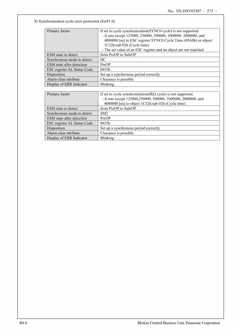
No. SX-DSV03307 - 273 -
R8.0 Motion Control Business Unit, Panasonic Corporation
8) Synchronization cycle error protection (Err81.0)
Primary factor If set to cycle synchronization(SYNC0 cycle) is not supported. - It sets except 125000, 250000, 500000, 1000000, 2000000, and
4000000 [ns] to ESC register SYNC0 Cycle Time (09A0h) or object 1C32h:sub 02h (Cycle time).
- The set value of an ESC register and an object are not matched. ESM state to detect from PreOP to SafeOP Synchronous mode to detect DC ESM state after detection PreOP ESC register AL Status Code 0035h Disposition Set up a synchronous period correctly. Alarm clear attribute Clearance is possible. Display of ERR Indicator Blinking
Primary factor If set to cycle synchronization(IRQ cycle) is not supported.
- It sets except 125000,250000, 500000, 1000000, 2000000, and 4000000 [ns] to object 1C32h:sub 02h (Cycle time).
ESM state to detect from PreOP to SafeOP Synchronous mode to detect SM2 ESM state after detection PreOP ESC register AL Status Code 0035h Disposition Set up a synchronous period correctly. Alarm clear attribute Clearance is possible. Display of ERR Indicator Blinking
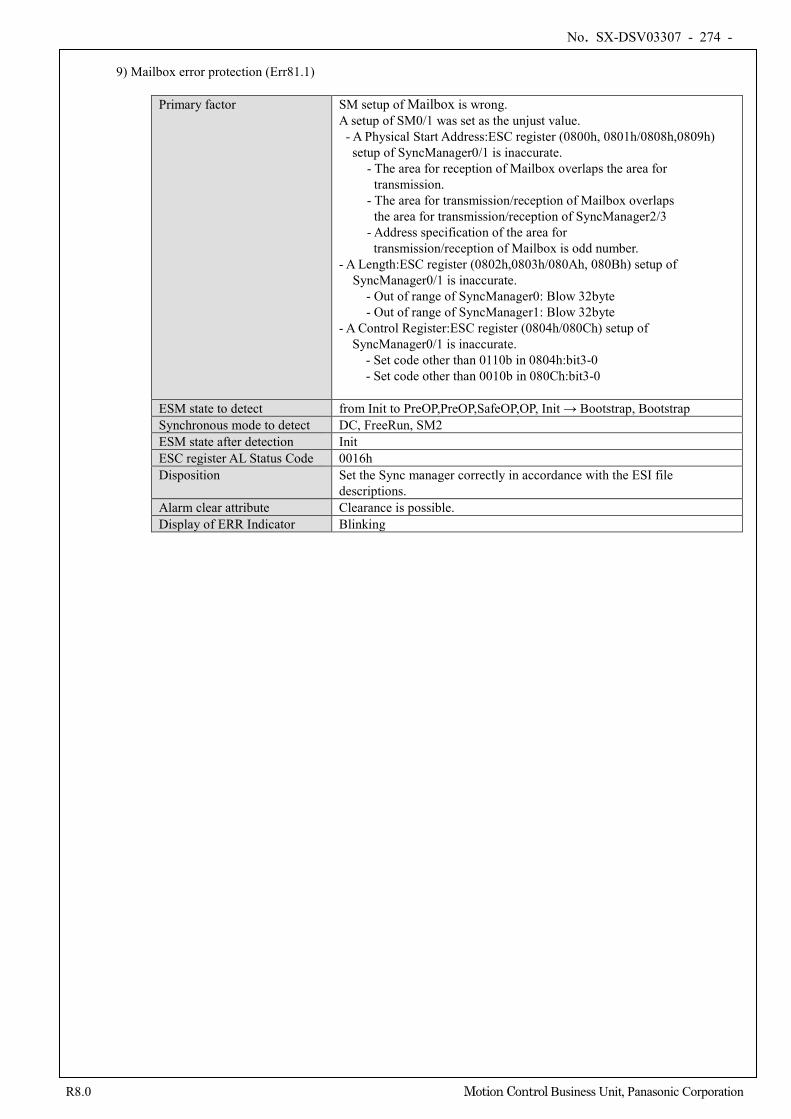
No. SX-DSV03307 - 274 -
R8.0 Motion Control Business Unit, Panasonic Corporation
9) Mailbox error protection (Err81.1)
Primary factor SM setup of Mailbox is wrong. A setup of SM0/1 was set as the unjust value. - A Physical Start Address:ESC register (0800h, 0801h/0808h,0809h)
setup of SyncManager0/1 is inaccurate. - The area for reception of Mailbox overlaps the area for
transmission. - The area for transmission/reception of Mailbox overlaps
the area for transmission/reception of SyncManager2/3 - Address specification of the area for transmission/reception of Mailbox is odd number.
- A Length:ESC register (0802h,0803h/080Ah, 080Bh) setup of SyncManager0/1 is inaccurate.
- Out of range of SyncManager0: Blow 32byte - Out of range of SyncManager1: Blow 32byte
- A Control Register:ESC register (0804h/080Ch) setup of SyncManager0/1 is inaccurate.
- Set code other than 0110b in 0804h:bit3-0 - Set code other than 0010b in 080Ch:bit3-0
ESM state to detect from Init to PreOP,PreOP,SafeOP,OP, Init → Bootstrap, Bootstrap Synchronous mode to detect DC, FreeRun, SM2 ESM state after detection Init ESC register AL Status Code 0016h Disposition Set the Sync manager correctly in accordance with the ESI file
descriptions. Alarm clear attribute Clearance is possible. Display of ERR Indicator Blinking
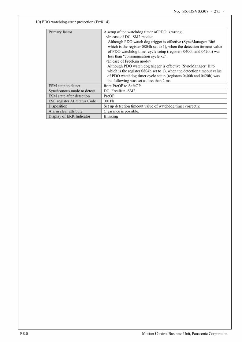
No. SX-DSV03307 - 275 -
R8.0 Motion Control Business Unit, Panasonic Corporation
10) PDO watchdog error protection (Err81.4)
Primary factor A setup of the watchdog timer of PDO is wrong. <In case of DC, SM2 mode>
Although PDO watch dog trigger is effective (SyncManager: Bit6 which is the register 0804h set to 1), when the detection timeout value of PDO watchdog timer cycle setup (registers 0400h and 0420h) was less than "communication cycle x2".
<In case of FreeRun mode> Although PDO watch dog trigger is effective (SyncManager: Bit6 which is the register 0804h set to 1), when the detection timeout value of PDO watchdog timer cycle setup (registers 0400h and 0420h) was the following was set as less than 2 ms.
ESM state to detect from PreOP to SafeOP Synchronous mode to detect DC, FreeRun, SM2 ESM state after detection PreOP ESC register AL Status Code 001Fh Disposition Set up detection timeout value of watchdog timer correctly. Alarm clear attribute Clearance is possible. Display of ERR Indicator Blinking
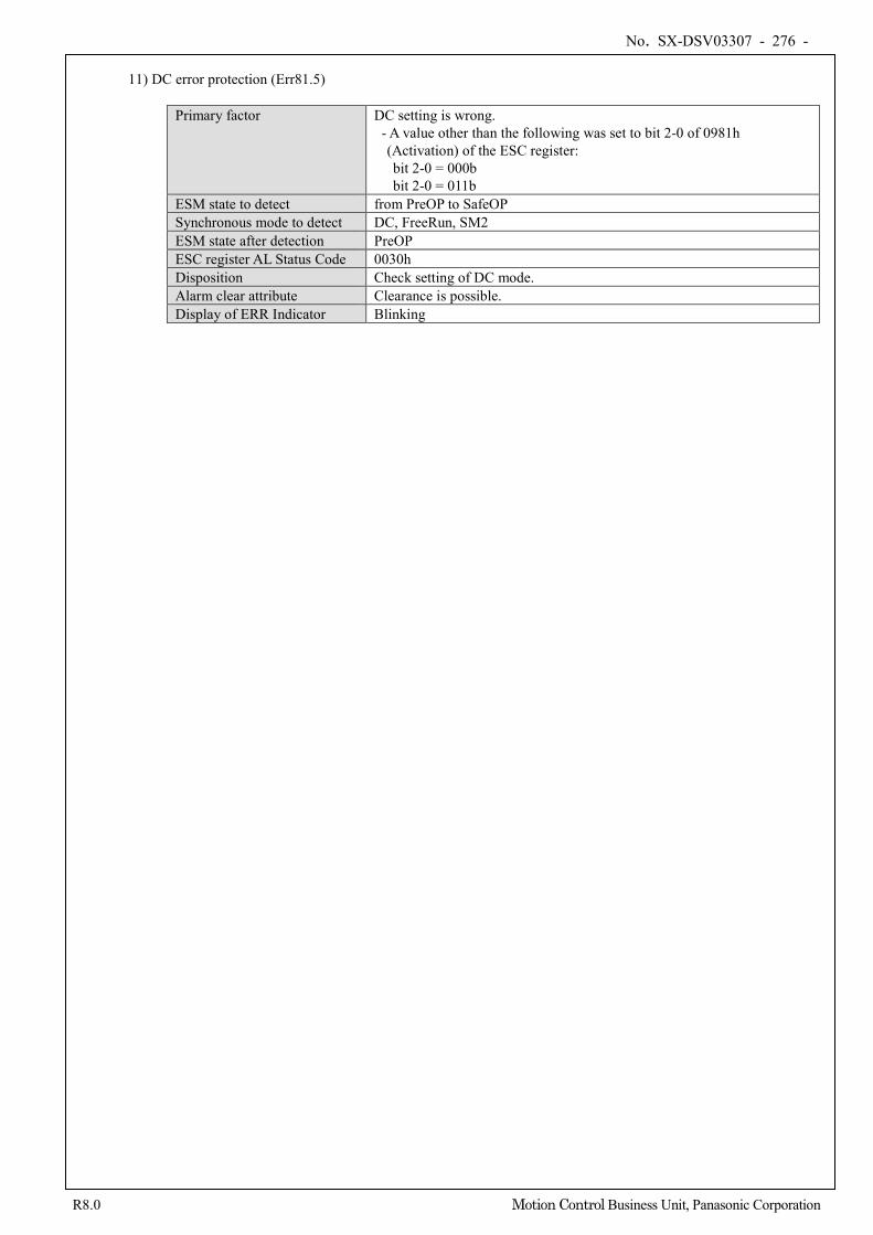
No. SX-DSV03307 - 276 -
R8.0 Motion Control Business Unit, Panasonic Corporation
11) DC error protection (Err81.5)
Primary factor DC setting is wrong. - A value other than the following was set to bit 2-0 of 0981h
(Activation) of the ESC register: bit 2-0 = 000b bit 2-0 = 011b
ESM state to detect from PreOP to SafeOP Synchronous mode to detect DC, FreeRun, SM2 ESM state after detection PreOP ESC register AL Status Code 0030h Disposition Check setting of DC mode. Alarm clear attribute Clearance is possible. Display of ERR Indicator Blinking
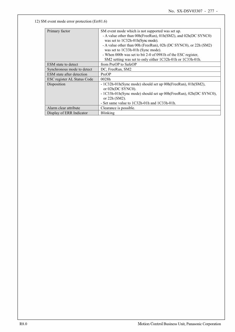
No. SX-DSV03307 - 277 -
R8.0 Motion Control Business Unit, Panasonic Corporation
12) SM event mode error protection (Err81.6)
Primary factor SM event mode which is not supported was set up. - A value other than 00h(FreeRun), 01h(SM2), and 02h(DC SYNC0)
was set to 1C32h-01h(Sync mode). - A value other than 00h (FreeRun), 02h (DC SYNC0), or 22h (SM2)
was set to 1C33h-01h (Sync mode). - When 000b was set to bit 2-0 of 0981h of the ESC register, SM2 setting was set to only either 1C32h-01h or 1C33h-01h.
ESM state to detect from PreOP to SafeOP Synchronous mode to detect DC, FreeRun, SM2 ESM state after detection PreOP ESC register AL Status Code 0028h Disposition - 1C32h-01h(Sync mode) should set up 00h(FreeRun), 01h(SM2),
or 02h(DC SYNC0). - 1C33h-01h(Sync mode) should set up 00h(FreeRun), 02h(DC SYNC0),
or 22h (SM2). - Set same value to 1C32h-01h and 1C33h-01h.
Alarm clear attribute Clearance is possible. Display of ERR Indicator Blinking
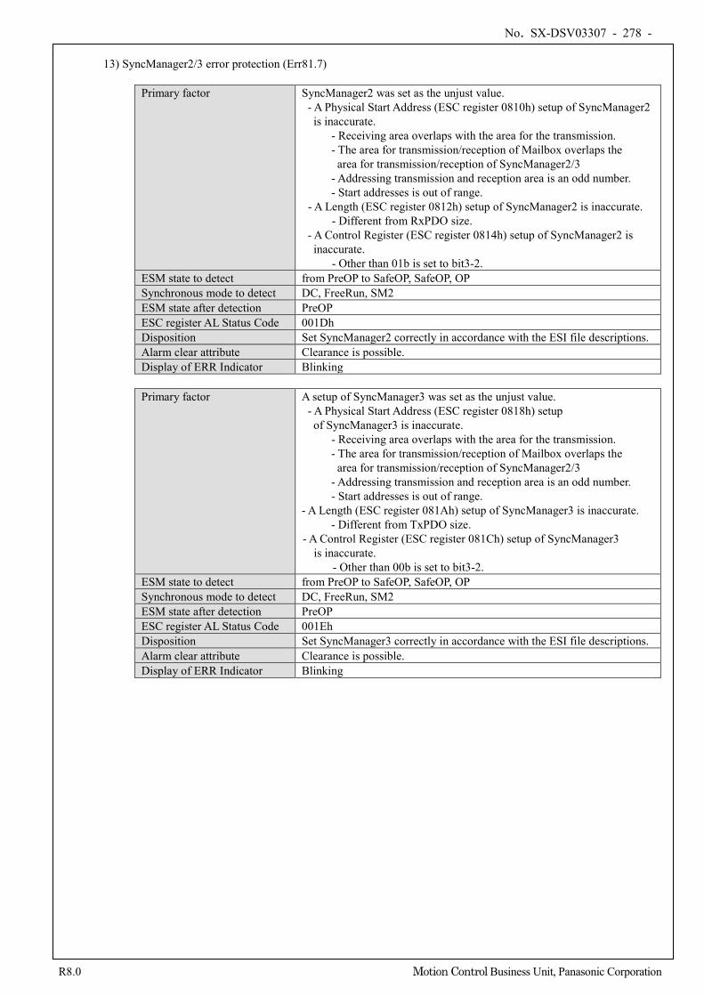
No. SX-DSV03307 - 278 -
R8.0 Motion Control Business Unit, Panasonic Corporation
13) SyncManager2/3 error protection (Err81.7)
Primary factor SyncManager2 was set as the unjust value. - A Physical Start Address (ESC register 0810h) setup of SyncManager2
is inaccurate. - Receiving area overlaps with the area for the transmission. - The area for transmission/reception of Mailbox overlaps the
area for transmission/reception of SyncManager2/3 - Addressing transmission and reception area is an odd number. - Start addresses is out of range.
- A Length (ESC register 0812h) setup of SyncManager2 is inaccurate. - Different from RxPDO size.
- A Control Register (ESC register 0814h) setup of SyncManager2 is inaccurate.
- Other than 01b is set to bit3-2. ESM state to detect from PreOP to SafeOP, SafeOP, OP Synchronous mode to detect DC, FreeRun, SM2 ESM state after detection PreOP ESC register AL Status Code 001Dh Disposition Set SyncManager2 correctly in accordance with the ESI file descriptions. Alarm clear attribute Clearance is possible. Display of ERR Indicator Blinking
Primary factor A setup of SyncManager3 was set as the unjust value.
- A Physical Start Address (ESC register 0818h) setup of SyncManager3 is inaccurate.
- Receiving area overlaps with the area for the transmission. - The area for transmission/reception of Mailbox overlaps the
area for transmission/reception of SyncManager2/3 - Addressing transmission and reception area is an odd number.
- Start addresses is out of range. - A Length (ESC register 081Ah) setup of SyncManager3 is inaccurate.
- Different from TxPDO size. - A Control Register (ESC register 081Ch) setup of SyncManager3
is inaccurate. - Other than 00b is set to bit3-2.
ESM state to detect from PreOP to SafeOP, SafeOP, OP Synchronous mode to detect DC, FreeRun, SM2 ESM state after detection PreOP ESC register AL Status Code 001Eh Disposition Set SyncManager3 correctly in accordance with the ESI file descriptions. Alarm clear attribute Clearance is possible. Display of ERR Indicator Blinking

No. SX-DSV03307 - 279 -
R8.0 Motion Control Business Unit, Panasonic Corporation
14) TxPDO assignment error protection (Err85.0)
Primary factor The data size of TxPDO map is set up exceeding 32 bytes. ESM state to detect from PreOP to SafeOP Synchronous mode to detect DC, FreeRun, SM2 ESM state after detection PreOP ESC register AL Status Code 0024h Disposition TxPDO data size is set up within 32 bytes. Alarm clear attribute Clearance is possible. Display of ERR Indicator Blinking
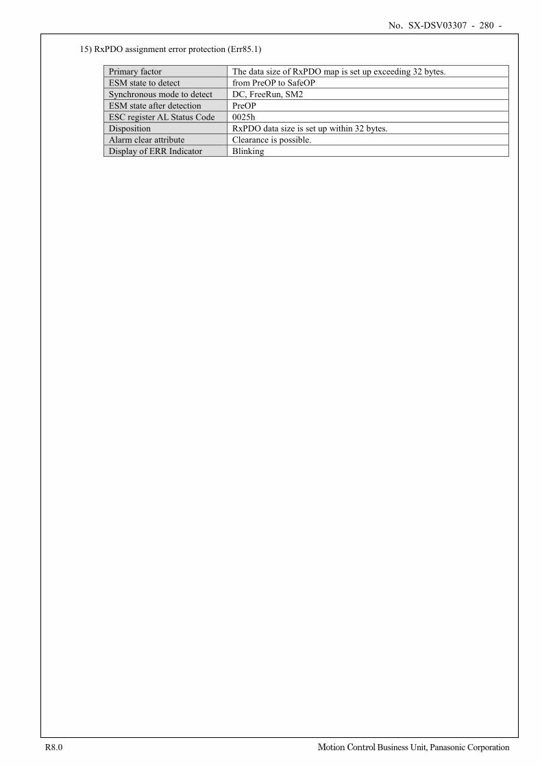
No. SX-DSV03307 - 280 -
R8.0 Motion Control Business Unit, Panasonic Corporation
15) RxPDO assignment error protection (Err85.1)
Primary factor The data size of RxPDO map is set up exceeding 32 bytes. ESM state to detect from PreOP to SafeOP Synchronous mode to detect DC, FreeRun, SM2 ESM state after detection PreOP ESC register AL Status Code 0025h Disposition RxPDO data size is set up within 32 bytes. Alarm clear attribute Clearance is possible. Display of ERR Indicator Blinking
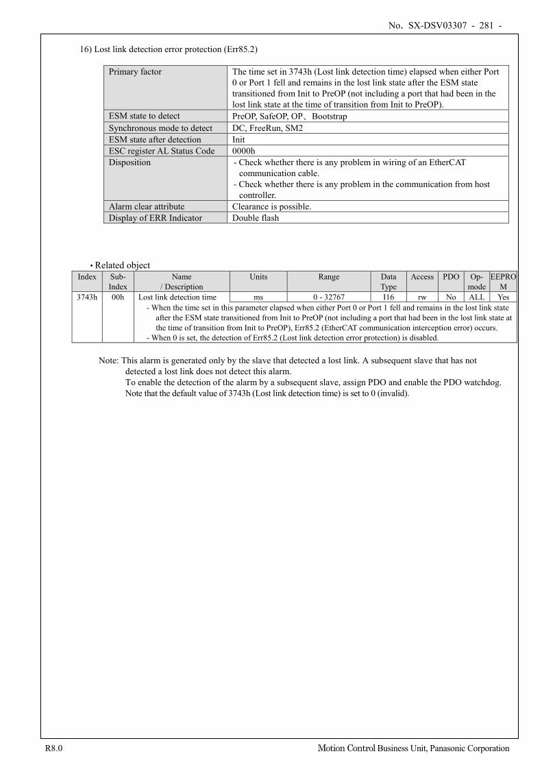
No. SX-DSV03307 - 281 -
R8.0 Motion Control Business Unit, Panasonic Corporation
16) Lost link detection error protection (Err85.2)
Primary factor The time set in 3743h (Lost link detection time) elapsed when either Port 0 or Port 1 fell and remains in the lost link state after the ESM state transitioned from Init to PreOP (not including a port that had been in the lost link state at the time of transition from Init to PreOP).
ESM state to detect PreOP, SafeOP, OP、Bootstrap Synchronous mode to detect DC, FreeRun, SM2 ESM state after detection Init ESC register AL Status Code 0000h Disposition - Check whether there is any problem in wiring of an EtherCAT
communication cable. - Check whether there is any problem in the communication from host
controller. Alarm clear attribute Clearance is possible. Display of ERR Indicator Double flash
• Related object Index Sub-
Index Name
/ Description Units Range Data
Type Access PDO Op-
mode EEPRO
M 3743h 00h Lost link detection time ms 0 - 32767 I16 rw No ALL Yes
- When the time set in this parameter elapsed when either Port 0 or Port 1 fell and remains in the lost link state after the ESM state transitioned from Init to PreOP (not including a port that had been in the lost link state at the time of transition from Init to PreOP), Err85.2 (EtherCAT communication interception error) occurs.
- When 0 is set, the detection of Err85.2 (Lost link detection error protection) is disabled.
Note: This alarm is generated only by the slave that detected a lost link. A subsequent slave that has not detected a lost link does not detect this alarm. To enable the detection of the alarm by a subsequent slave, assign PDO and enable the PDO watchdog. Note that the default value of 3743h (Lost link detection time) is set to 0 (invalid).
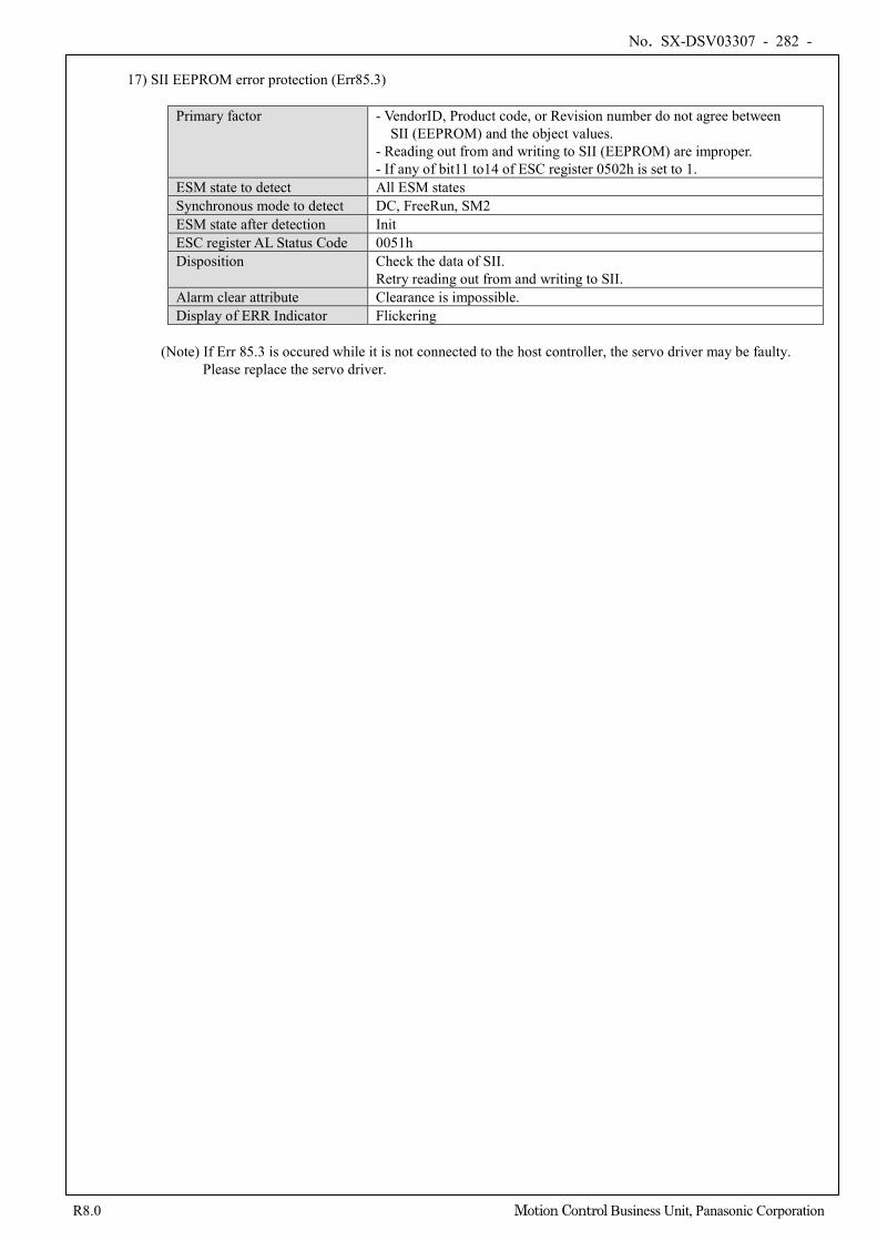
No. SX-DSV03307 - 282 -
R8.0 Motion Control Business Unit, Panasonic Corporation
17) SII EEPROM error protection (Err85.3)
Primary factor - VendorID, Product code, or Revision number do not agree between SII (EEPROM) and the object values.
- Reading out from and writing to SII (EEPROM) are improper. - If any of bit11 to14 of ESC register 0502h is set to 1.
ESM state to detect All ESM states Synchronous mode to detect DC, FreeRun, SM2 ESM state after detection Init ESC register AL Status Code 0051h Disposition Check the data of SII.
Retry reading out from and writing to SII. Alarm clear attribute Clearance is impossible. Display of ERR Indicator Flickering
(Note) If Err 85.3 is occured while it is not connected to the host controller, the servo driver may be faulty.
Please replace the servo driver.
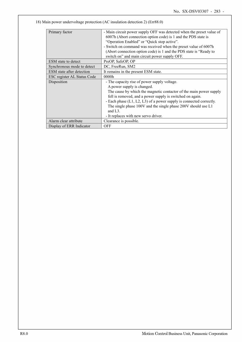
No. SX-DSV03307 - 283 -
R8.0 Motion Control Business Unit, Panasonic Corporation
18) Main power undervoltage protection (AC insulation detection 2) (Err88.0)
Primary factor - Main circuit power supply OFF was detected when the preset value of 6007h (Abort connection option code) is 1 and the PDS state is “Operation Enabled” or “Quick stop active”.
- Switch on command was received when the preset value of 6007h (Abort connection option code) is 1 and the PDS state is “Ready to switch on” and main circuit power supply OFF.
ESM state to detect PreOP, SafeOP, OP Synchronous mode to detect DC, FreeRun, SM2 ESM state after detection It remains in the present ESM state. ESC register AL Status Code 0000h Disposition - The capacity rise of power supply voltage.
A power supply is changed. The cause by which the magnetic contactor of the main power supply fell is removed, and a power supply is switched on again.
- Each phase (L1, L2, L3) of a power supply is connected correctly. The single phase 100V and the single phase 200V should use L1 and L3.
- It replaces with new servo driver. Alarm clear attribute Clearance is possible. Display of ERR Indicator OFF

No. SX-DSV03307 - 284 -
R8.0 Motion Control Business Unit, Panasonic Corporation
19) Control mode setting error protection (Err88.1)
Primary factor - The PDS state was changed to “Operation enabled” when the value set to 6060h (Modes of operation) is 0 and the value set to 6061h (Modes of operation display) is 0.
- Unsupported control mode is set to 6060h (Modes of operation).
ESM state to detect All the ESM states Synchronous mode to detect DC, FreeRun, SM2 ESM state after detection It remains in the present ESM state. ESC register AL Status Code 0000h Disposition - Check preset value of 6060h(Modes of operation).
- Check 2 degree of freedom control related parameter Pr 6.47 bit 0 and bit3 Since parameter shipping values are different from MINAS-A5BL series, please be careful.
Alarm clear attribute Clearance is possible. Display of ERR Indicator OFF
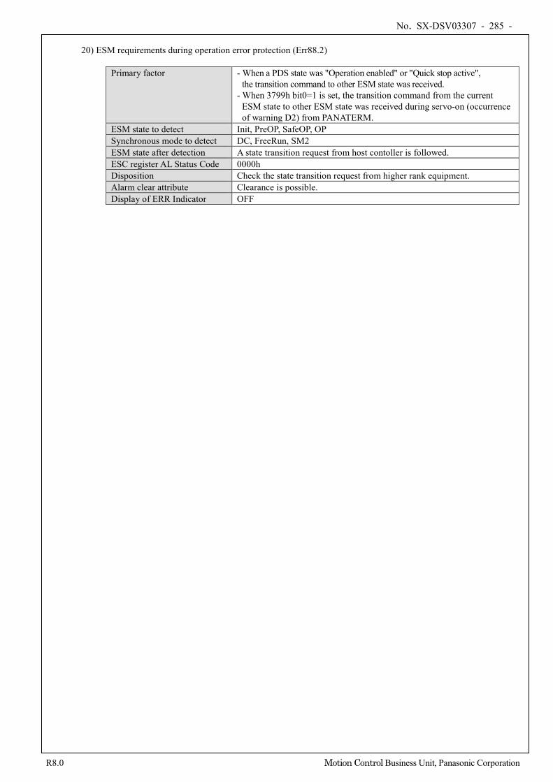
No. SX-DSV03307 - 285 -
R8.0 Motion Control Business Unit, Panasonic Corporation
20) ESM requirements during operation error protection (Err88.2)
Primary factor - When a PDS state was "Operation enabled" or "Quick stop active", the transition command to other ESM state was received.
- When 3799h bit0=1 is set, the transition command from the current ESM state to other ESM state was received during servo-on (occurrence of warning D2) from PANATERM.
ESM state to detect Init, PreOP, SafeOP, OP Synchronous mode to detect DC, FreeRun, SM2 ESM state after detection A state transition request from host contoller is followed. ESC register AL Status Code 0000h Disposition Check the state transition request from higher rank equipment. Alarm clear attribute Clearance is possible. Display of ERR Indicator OFF
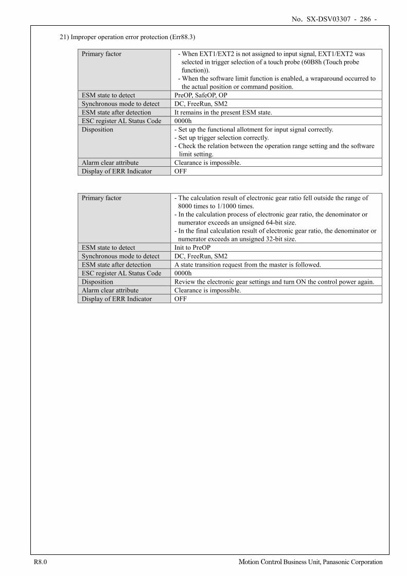
No. SX-DSV03307 - 286 -
R8.0 Motion Control Business Unit, Panasonic Corporation
21) Improper operation error protection (Err88.3)
Primary factor - When EXT1/EXT2 is not assigned to input signal, EXT1/EXT2 was selected in trigger selection of a touch probe (60B8h (Touch probe function)).
- When the software limit function is enabled, a wraparound occurred to the actual position or command position.
ESM state to detect PreOP, SafeOP, OP Synchronous mode to detect DC, FreeRun, SM2 ESM state after detection It remains in the present ESM state. ESC register AL Status Code 0000h Disposition - Set up the functional allotment for input signal correctly.
- Set up trigger selection correctly. - Check the relation between the operation range setting and the software
limit setting. Alarm clear attribute Clearance is impossible. Display of ERR Indicator OFF
Primary factor - The calculation result of electronic gear ratio fell outside the range of 8000 times to 1/1000 times.
- In the calculation process of electronic gear ratio, the denominator or numerator exceeds an unsigned 64-bit size.
- In the final calculation result of electronic gear ratio, the denominator or numerator exceeds an unsigned 32-bit size.
ESM state to detect Init to PreOP Synchronous mode to detect DC, FreeRun, SM2 ESM state after detection A state transition request from the master is followed. ESC register AL Status Code 0000h Disposition Review the electronic gear settings and turn ON the control power again. Alarm clear attribute Clearance is impossible. Display of ERR Indicator OFF
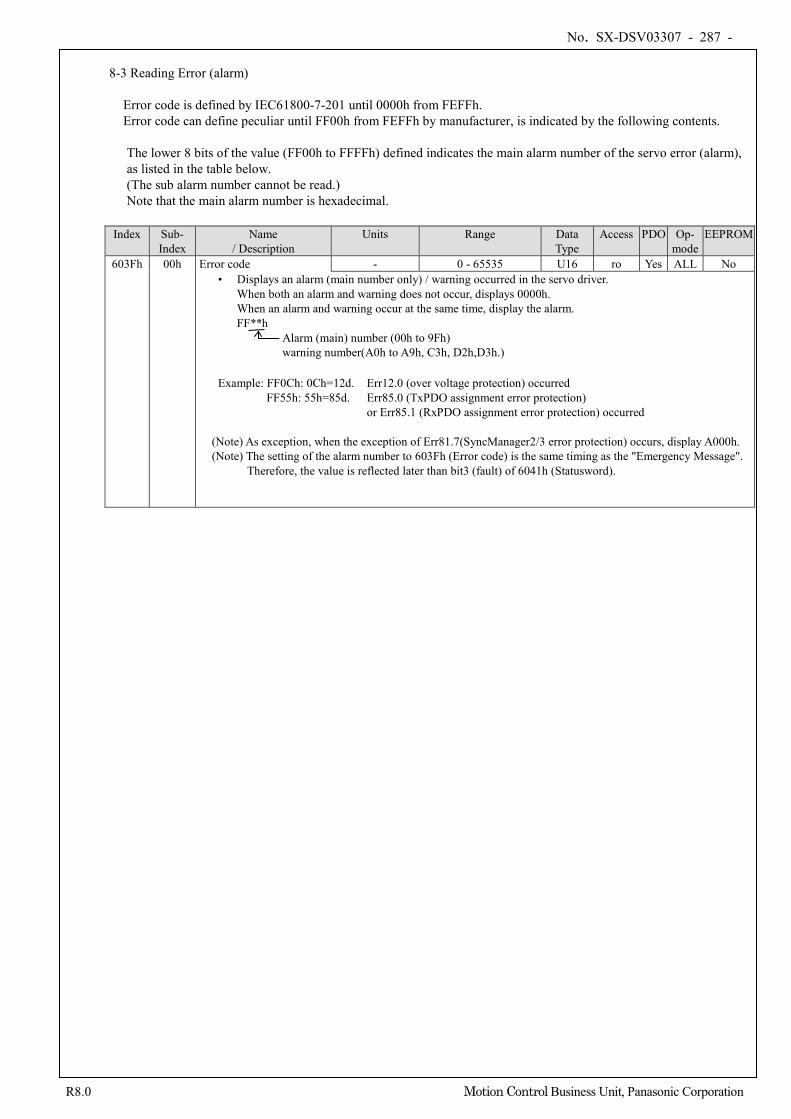
No. SX-DSV03307 - 287 -
R8.0 Motion Control Business Unit, Panasonic Corporation
8-3 Reading Error (alarm)
Error code is defined by IEC61800-7-201 until 0000h from FEFFh. Error code can define peculiar until FF00h from FEFFh by manufacturer, is indicated by the following contents. The lower 8 bits of the value (FF00h to FFFFh) defined indicates the main alarm number of the servo error (alarm), as listed in the table below. (The sub alarm number cannot be read.) Note that the main alarm number is hexadecimal.
Index Sub-
Index Name
/ Description Units Range Data
Type Access PDO Op-
mode EEPROM
603Fh 00h Error code - 0 - 65535 U16 ro Yes ALL No • Displays an alarm (main number only) / warning occurred in the servo driver.
When both an alarm and warning does not occur, displays 0000h. When an alarm and warning occur at the same time, display the alarm. FF**h
Alarm (main) number (00h to 9Fh) warning number(A0h to A9h, C3h, D2h,D3h.)
Example: FF0Ch: 0Ch=12d. Err12.0 (over voltage protection) occurred FF55h: 55h=85d. Err85.0 (TxPDO assignment error protection) or Err85.1 (RxPDO assignment error protection) occurred
(Note) As exception, when the exception of Err81.7(SyncManager2/3 error protection) occurs, display A000h. (Note) The setting of the alarm number to 603Fh (Error code) is the same timing as the "Emergency Message".
Therefore, the value is reflected later than bit3 (fault) of 6041h (Statusword).
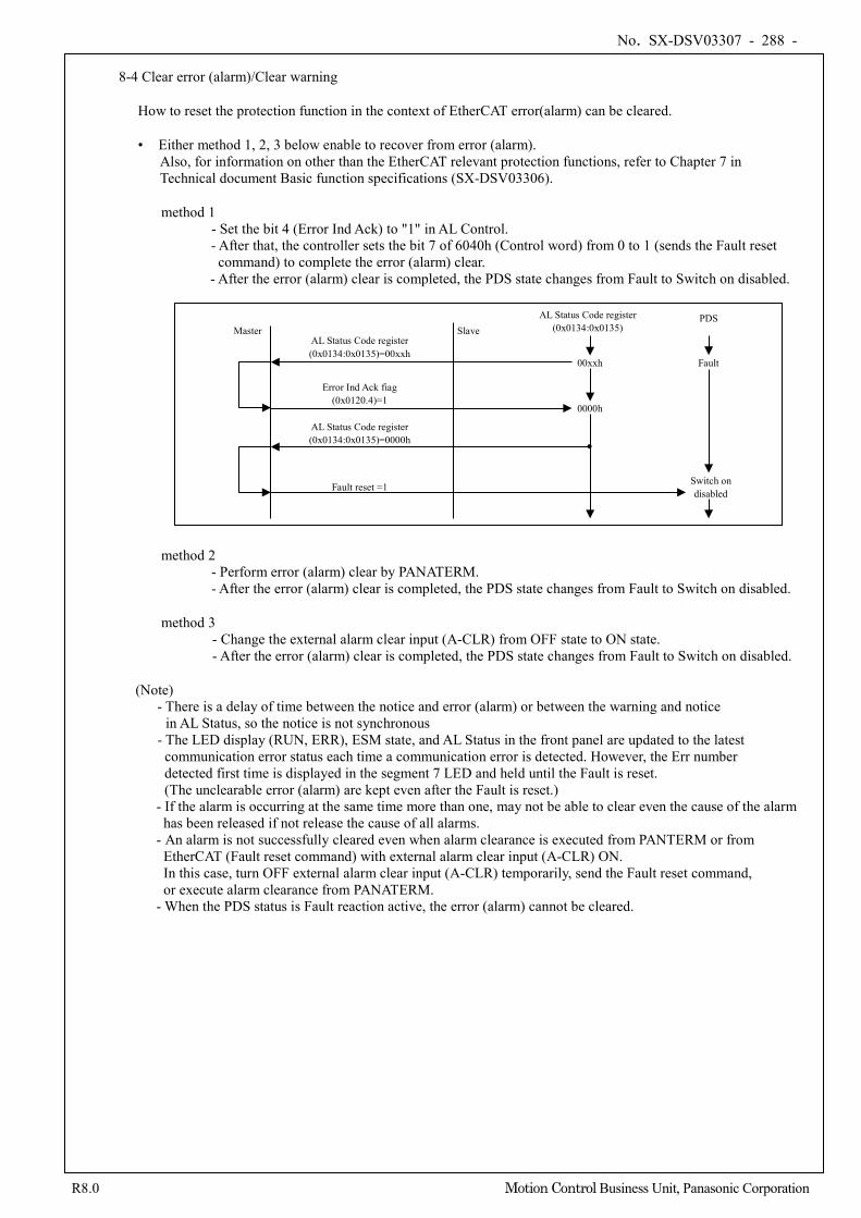
No. SX-DSV03307 - 288 -
R8.0 Motion Control Business Unit, Panasonic Corporation
8-4 Clear error (alarm)/Clear warning
How to reset the protection function in the context of EtherCAT error(alarm) can be cleared.
• Either method 1, 2, 3 below enable to recover from error (alarm). Also, for information on other than the EtherCAT relevant protection functions, refer to Chapter 7 in Technical document Basic function specifications (SX-DSV03306).
method 1 - Set the bit 4 (Error Ind Ack) to "1" in AL Control. - After that, the controller sets the bit 7 of 6040h (Control word) from 0 to 1 (sends the Fault reset command) to complete the error (alarm) clear.
- After the error (alarm) clear is completed, the PDS state changes from Fault to Switch on disabled.
method 2 - Perform error (alarm) clear by PANATERM. - After the error (alarm) clear is completed, the PDS state changes from Fault to Switch on disabled.
method 3 - Change the external alarm clear input (A-CLR) from OFF state to ON state. - After the error (alarm) clear is completed, the PDS state changes from Fault to Switch on disabled.
(Note) - There is a delay of time between the notice and error (alarm) or between the warning and notice
in AL Status, so the notice is not synchronous - The LED display (RUN, ERR), ESM state, and AL Status in the front panel are updated to the latest communication error status each time a communication error is detected. However, the Err number detected first time is displayed in the segment 7 LED and held until the Fault is reset. (The unclearable error (alarm) are kept even after the Fault is reset.)
- If the alarm is occurring at the same time more than one, may not be able to clear even the cause of the alarm has been released if not release the cause of all alarms.
- An alarm is not successfully cleared even when alarm clearance is executed from PANTERM or from EtherCAT (Fault reset command) with external alarm clear input (A-CLR) ON. In this case, turn OFF external alarm clear input (A-CLR) temporarily, send the Fault reset command, or execute alarm clearance from PANATERM.
- When the PDS status is Fault reaction active, the error (alarm) cannot be cleared.
Master Slave PDS
Fault 00xxh
AL Status Code register (0x0134:0x0135)=00xxh
0000h
Error Ind Ack fiag (0x0120.4)=1
AL Status Code register (0x0134:0x0135)=0000h
Fault reset =1 Switch on disabled
AL Status Code register (0x0134:0x0135)
●
No. SX-DSV03307 - 289 -
R8.0 Motion Control Business Unit, Panasonic Corporation
• How to clear warning - When warning latch state is set to latch setting by 3627 h (Warning latch state setup), after generating warnings to be latched, the warning will not be cleared even if the cause is released. In this case, you can clear the warning that is currently occurring by setting the bit 7 of 6040h (Control word)
from 0 to 1 (send the Fault reset command) via EtherCAT, by executing the error (alarm) clear from PANATERM or by switching the external alarm clear input (A - CLR) from OFF to ON. However, when the PDS status is Fault reaction active, the warning cannot be cleared.
- When an external alarm clear input (A-CLR) is in ON state, warning does not occur.
No. SX-DSV03307 - 290 -
R8.0 Motion Control Business Unit, Panasonic Corporation
8-5 Other, error(alarm) / warning ralated function
Function related error(alarm) and warning have been described in addition to this section, refer to the section below.
- Abort message … Section 3-6-1 - Emergency message … Section 3-6-1 - 1001h(Error register) … Section 3-6-1, 5-2 - 10F3h(Diagnosis history) … Section 3-6-1, 5-7 - 603Fh(Error code) … Section 3-6-1
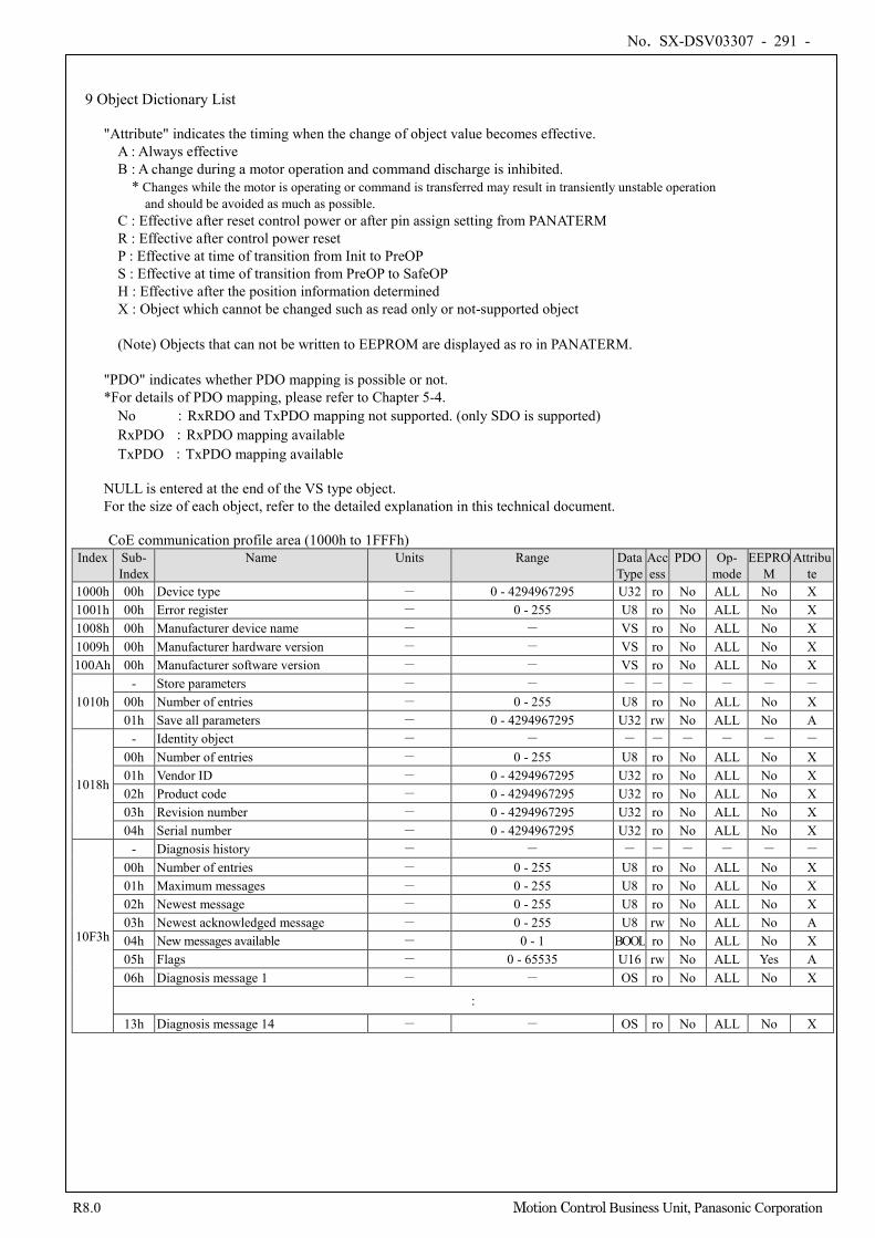
No. SX-DSV03307 - 291 -
R8.0 Motion Control Business Unit, Panasonic Corporation
9 Object Dictionary List
"Attribute" indicates the timing when the change of object value becomes effective. A : Always effective B : A change during a motor operation and command discharge is inhibited.
* Changes while the motor is operating or command is transferred may result in transiently unstable operation and should be avoided as much as possible.
C : Effective after reset control power or after pin assign setting from PANATERM R : Effective after control power reset P : Effective at time of transition from Init to PreOP S : Effective at time of transition from PreOP to SafeOP H : Effective after the position information determined X : Object which cannot be changed such as read only or not-supported object (Note) Objects that can not be written to EEPROM are displayed as ro in PANATERM.
"PDO" indicates whether PDO mapping is possible or not. *For details of PDO mapping, please refer to Chapter 5-4.
No :RxRDO and TxPDO mapping not supported. (only SDO is supported) RxPDO :RxPDO mapping available TxPDO :TxPDO mapping available
NULL is entered at the end of the VS type object. For the size of each object, refer to the detailed explanation in this technical document.
CoE communication profile area (1000h to 1FFFh)
Index Sub- Index
Name Units Range Data Type
Access
PDO Op- mode
EEPROM
Attribute
1000h 00h Device type - 0 - 4294967295 U32 ro No ALL No X 1001h 00h Error register - 0 - 255 U8 ro No ALL No X 1008h 00h Manufacturer device name - - VS ro No ALL No X 1009h 00h Manufacturer hardware version - - VS ro No ALL No X 100Ah 00h Manufacturer software version - - VS ro No ALL No X
1010h - Store parameters - - - - - - - -
00h Number of entries - 0 - 255 U8 ro No ALL No X 01h Save all parameters - 0 - 4294967295 U32 rw No ALL No A
1018h
- Identity object - - - - - - - - 00h Number of entries - 0 - 255 U8 ro No ALL No X 01h Vendor ID - 0 - 4294967295 U32 ro No ALL No X 02h Product code - 0 - 4294967295 U32 ro No ALL No X 03h Revision number - 0 - 4294967295 U32 ro No ALL No X 04h Serial number - 0 - 4294967295 U32 ro No ALL No X
10F3h
- Diagnosis history - - - - - - - - 00h Number of entries - 0 - 255 U8 ro No ALL No X 01h Maximum messages - 0 - 255 U8 ro No ALL No X 02h Newest message - 0 - 255 U8 ro No ALL No X 03h Newest acknowledged message - 0 - 255 U8 rw No ALL No A 04h New messages available - 0 - 1 BOOL ro No ALL No X 05h Flags - 0 - 65535 U16 rw No ALL Yes A 06h Diagnosis message 1 - - OS ro No ALL No X
:
13h Diagnosis message 14 - - OS ro No ALL No X
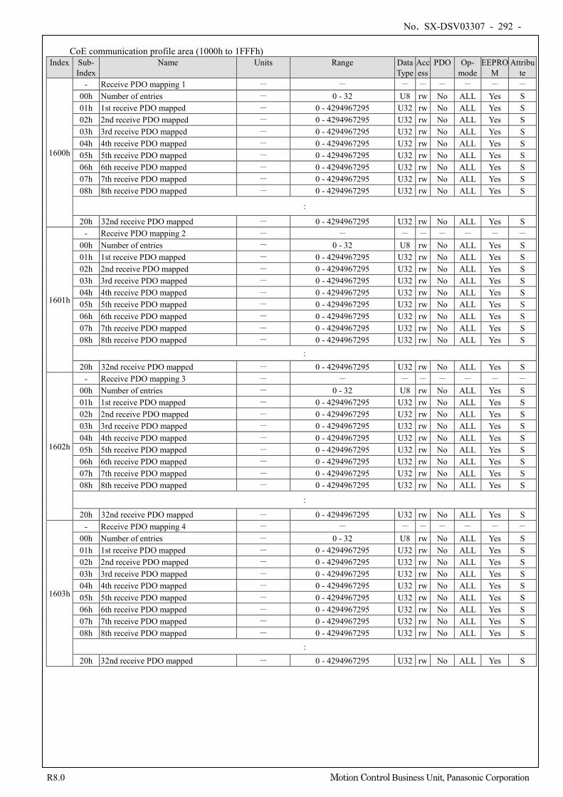
No. SX-DSV03307 - 292 -
R8.0 Motion Control Business Unit, Panasonic Corporation
CoE communication profile area (1000h to 1FFFh)
Index Sub- Index
Name Units Range Data Type
Access
PDO Op- mode
EEPROM
Attribute
1600h
- Receive PDO mapping 1 - - - - - - - - 00h Number of entries - 0 - 32 U8 rw No ALL Yes S 01h 1st receive PDO mapped - 0 - 4294967295 U32 rw No ALL Yes S 02h 2nd receive PDO mapped - 0 - 4294967295 U32 rw No ALL Yes S 03h 3rd receive PDO mapped - 0 - 4294967295 U32 rw No ALL Yes S 04h 4th receive PDO mapped - 0 - 4294967295 U32 rw No ALL Yes S 05h 5th receive PDO mapped - 0 - 4294967295 U32 rw No ALL Yes S 06h 6th receive PDO mapped - 0 - 4294967295 U32 rw No ALL Yes S 07h 7th receive PDO mapped - 0 - 4294967295 U32 rw No ALL Yes S 08h 8th receive PDO mapped - 0 - 4294967295 U32 rw No ALL Yes S
:
20h 32nd receive PDO mapped - 0 - 4294967295 U32 rw No ALL Yes S
1601h
- Receive PDO mapping 2 - - - - - - - - 00h Number of entries - 0 - 32 U8 rw No ALL Yes S 01h 1st receive PDO mapped - 0 - 4294967295 U32 rw No ALL Yes S 02h 2nd receive PDO mapped - 0 - 4294967295 U32 rw No ALL Yes S 03h 3rd receive PDO mapped - 0 - 4294967295 U32 rw No ALL Yes S 04h 4th receive PDO mapped - 0 - 4294967295 U32 rw No ALL Yes S 05h 5th receive PDO mapped - 0 - 4294967295 U32 rw No ALL Yes S 06h 6th receive PDO mapped - 0 - 4294967295 U32 rw No ALL Yes S 07h 7th receive PDO mapped - 0 - 4294967295 U32 rw No ALL Yes S 08h 8th receive PDO mapped - 0 - 4294967295 U32 rw No ALL Yes S
: 20h 32nd receive PDO mapped - 0 - 4294967295 U32 rw No ALL Yes S
1602h
- Receive PDO mapping 3 - - - - - - - - 00h Number of entries - 0 - 32 U8 rw No ALL Yes S 01h 1st receive PDO mapped - 0 - 4294967295 U32 rw No ALL Yes S 02h 2nd receive PDO mapped - 0 - 4294967295 U32 rw No ALL Yes S 03h 3rd receive PDO mapped - 0 - 4294967295 U32 rw No ALL Yes S 04h 4th receive PDO mapped - 0 - 4294967295 U32 rw No ALL Yes S 05h 5th receive PDO mapped - 0 - 4294967295 U32 rw No ALL Yes S 06h 6th receive PDO mapped - 0 - 4294967295 U32 rw No ALL Yes S 07h 7th receive PDO mapped - 0 - 4294967295 U32 rw No ALL Yes S 08h 8th receive PDO mapped - 0 - 4294967295 U32 rw No ALL Yes S
:
20h 32nd receive PDO mapped - 0 - 4294967295 U32 rw No ALL Yes S
1603h
- Receive PDO mapping 4 - - - - - - - - 00h Number of entries - 0 - 32 U8 rw No ALL Yes S 01h 1st receive PDO mapped - 0 - 4294967295 U32 rw No ALL Yes S 02h 2nd receive PDO mapped - 0 - 4294967295 U32 rw No ALL Yes S 03h 3rd receive PDO mapped - 0 - 4294967295 U32 rw No ALL Yes S 04h 4th receive PDO mapped - 0 - 4294967295 U32 rw No ALL Yes S 05h 5th receive PDO mapped - 0 - 4294967295 U32 rw No ALL Yes S 06h 6th receive PDO mapped - 0 - 4294967295 U32 rw No ALL Yes S 07h 7th receive PDO mapped - 0 - 4294967295 U32 rw No ALL Yes S 08h 8th receive PDO mapped - 0 - 4294967295 U32 rw No ALL Yes S
: 20h 32nd receive PDO mapped - 0 - 4294967295 U32 rw No ALL Yes S

No. SX-DSV03307 - 293 -
R8.0 Motion Control Business Unit, Panasonic Corporation
CoE communication profile area (1000h to 1FFFh)
Index Sub- Index
Name Units Range Data Type
Access
PDO Op- mode
EEPROM
Attribute
1A00h
- Transmit PDO mapping 1 - - - - - - - - 00h Number of entries - 0 - 32 U8 rw No ALL Yes S 01h 1st transmit PDO mapped - 0 - 4294967295 U32 rw No ALL Yes S 02h 2nd transmit PDO mapped - 0 - 4294967295 U32 rw No ALL Yes S 03h 3rd transmit PDO mapped - 0 - 4294967295 U32 rw No ALL Yes S 04h 4th transmit PDO mapped - 0 - 4294967295 U32 rw No ALL Yes S 05h 5th transmit PDO mapped - 0 - 4294967295 U32 rw No ALL Yes S 06h 6th transmit PDO mapped - 0 - 4294967295 U32 rw No ALL Yes S 07h 7th transmit PDO mapped - 0 - 4294967295 U32 rw No ALL Yes S 08h 8th transmit PDO mapped - 0 - 4294967295 U32 rw No ALL Yes S
:
20h 32nd transmit PDO mapped - 0 - 4294967295 U32 rw No ALL Yes S
1A01h
- Transmit PDO mapping 2 - - - - - - - - 00h Number of entries - 0 - 32 U8 rw No ALL Yes S 01h 1st transmit PDO mapped - 0 - 4294967295 U32 rw No ALL Yes S 02h 2nd transmit PDO mapped - 0 - 4294967295 U32 rw No ALL Yes S 03h 3rd transmit PDO mapped - 0 - 4294967295 U32 rw No ALL Yes S 04h 4th transmit PDO mapped - 0 - 4294967295 U32 rw No ALL Yes S 05h 5th transmit PDO mapped - 0 - 4294967295 U32 rw No ALL Yes S 06h 6th transmit PDO mapped - 0 - 4294967295 U32 rw No ALL Yes S 07h 7th transmit PDO mapped - 0 - 4294967295 U32 rw No ALL Yes S 08h 8th transmit PDO mapped - 0 - 4294967295 U32 rw No ALL Yes S
:
20h 32nd transmit PDO mapped - 0 - 4294967295 U32 rw No ALL Yes S
1A02h
- Transmit PDO mapping 3 - - - - - - - - 00h Number of entries - 0 - 32 U8 rw No ALL Yes S 01h 1st transmit PDO mapped - 0 - 4294967295 U32 rw No ALL Yes S 02h 2nd transmit PDO mapped - 0 - 4294967295 U32 rw No ALL Yes S 03h 3rd transmit PDO mapped - 0 - 4294967295 U32 rw No ALL Yes S 04h 4th transmit PDO mapped - 0 - 4294967295 U32 rw No ALL Yes S 05h 5th transmit PDO mapped - 0 - 4294967295 U32 rw No ALL Yes S 06h 6th transmit PDO mapped - 0 - 4294967295 U32 rw No ALL Yes S 07h 7th transmit PDO mapped - 0 - 4294967295 U32 rw No ALL Yes S 08h 8th transmit PDO mapped - 0 - 4294967295 U32 rw No ALL Yes S
: 20h 32nd transmit PDO mapped - 0 - 4294967295 U32 rw No ALL Yes S
1A03h
- Transmit PDO mapping 4 - - - - - - - - 00h Number of entries - 0 - 32 U8 rw No ALL Yes S 01h 1st transmit PDO mapped - 0 - 4294967295 U32 rw No ALL Yes S 02h 2nd transmit PDO mapped - 0 - 4294967295 U32 rw No ALL Yes S 03h 3rd transmit PDO mapped - 0 - 4294967295 U32 rw No ALL Yes S 04h 4th transmit PDO mapped - 0 - 4294967295 U32 rw No ALL Yes S 05h 5th transmit PDO mapped - 0 - 4294967295 U32 rw No ALL Yes S 06h 6th transmit PDO mapped - 0 - 4294967295 U32 rw No ALL Yes S 07h 7th transmit PDO mapped - 0 - 4294967295 U32 rw No ALL Yes S 08h 8th transmit PDO mapped - 0 - 4294967295 U32 rw No ALL Yes S
: 20h 32nd transmit PDO mapped - 0 - 4294967295 U32 rw No ALL Yes S
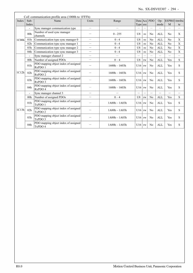
No. SX-DSV03307 - 294 -
R8.0 Motion Control Business Unit, Panasonic Corporation
CoE communication profile area (1000h to 1FFFh) Index Sub-
Index Name Units Range Data
Type Access
PDO Op- mode
EEPROM
Attribute
1C00h
- Sync manager communication type - - - - - - - -
00h Number of used sync manager channels - 0 - 255 U8 ro No ALL No X
01h Communication type sync manager 0 - 0 - 4 U8 ro No ALL No X 02h Communication type sync manager 1 - 0 - 4 U8 ro No ALL No X 03h Communication type sync manager 2 - 0 - 4 U8 ro No ALL No X 04h Communication type sync manager 3 - 0 - 4 U8 ro No ALL No X
1C12h
- Sync manager channel 2 - - - - - - - - 00h Number of assigned PDOs - 0 – 4 U8 rw No ALL Yes S
01h PDO mapping object index of assigned RxPDO 1 - 1600h – 1603h U16 rw No ALL Yes S
02h PDO mapping object index of assigned RxPDO 2 - 1600h – 1603h U16 rw No ALL Yes S
03h PDO mapping object index of assigned RxPDO 3 - 1600h – 1603h U16 rw No ALL Yes S
04h PDO mapping object index of assigned RxPDO 4 - 1600h – 1603h U16 rw No ALL Yes S
1C13h
- Sync manager channel 3 - - - - - - - - 00h Number of assigned PDOs - 0 – 4 U8 rw No ALL Yes S
01h PDO mapping object index of assigned TxPDO 1 - 1A00h – 1A03h U16 rw No ALL Yes S
02h PDO mapping object index of assigned TxPDO 2 - 1A00h – 1A03h U16 rw No ALL Yes S
03h PDO mapping object index of assigned TxPDO 3 - 1A00h – 1A03h U16 rw No ALL Yes S
04h PDO mapping object index of assigned TxPDO 4 - 1A00h – 1A03h U16 rw No ALL Yes S
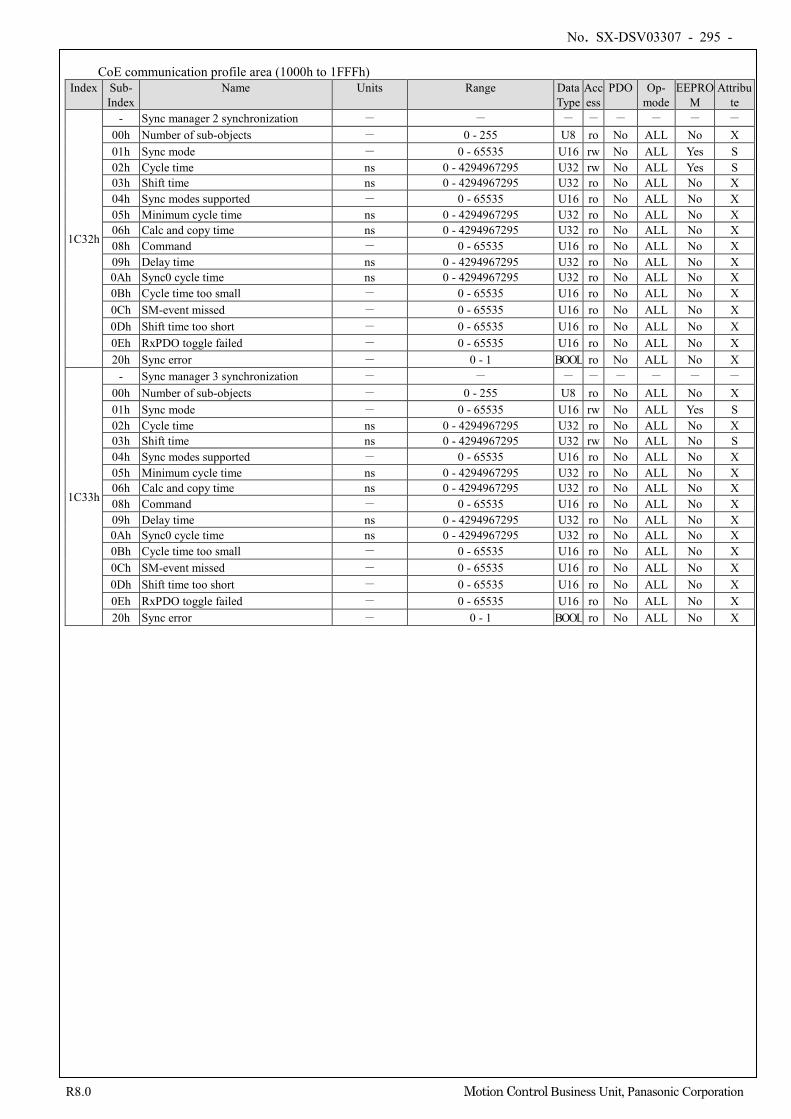
No. SX-DSV03307 - 295 -
R8.0 Motion Control Business Unit, Panasonic Corporation
CoE communication profile area (1000h to 1FFFh)
Index Sub- Index
Name Units Range Data Type
Access
PDO Op- mode
EEPROM
Attribute
1C32h
- Sync manager 2 synchronization - - - - - - - - 00h Number of sub-objects - 0 - 255 U8 ro No ALL No X 01h Sync mode - 0 - 65535 U16 rw No ALL Yes S 02h Cycle time ns 0 - 4294967295 U32 rw No ALL Yes S 03h Shift time ns 0 - 4294967295 U32 ro No ALL No X 04h Sync modes supported - 0 - 65535 U16 ro No ALL No X 05h Minimum cycle time ns 0 - 4294967295 U32 ro No ALL No X 06h Calc and copy time ns 0 - 4294967295 U32 ro No ALL No X 08h Command - 0 - 65535 U16 ro No ALL No X 09h Delay time ns 0 - 4294967295 U32 ro No ALL No X 0Ah Sync0 cycle time ns 0 - 4294967295 U32 ro No ALL No X 0Bh Cycle time too small - 0 - 65535 U16 ro No ALL No X 0Ch SM-event missed - 0 - 65535 U16 ro No ALL No X 0Dh Shift time too short - 0 - 65535 U16 ro No ALL No X 0Eh RxPDO toggle failed - 0 - 65535 U16 ro No ALL No X 20h Sync error - 0 - 1 BOOL ro No ALL No X
1C33h
- Sync manager 3 synchronization - - - - - - - - 00h Number of sub-objects - 0 - 255 U8 ro No ALL No X 01h Sync mode - 0 - 65535 U16 rw No ALL Yes S 02h Cycle time ns 0 - 4294967295 U32 ro No ALL No X 03h Shift time ns 0 - 4294967295 U32 rw No ALL No S 04h Sync modes supported - 0 - 65535 U16 ro No ALL No X 05h Minimum cycle time ns 0 - 4294967295 U32 ro No ALL No X 06h Calc and copy time ns 0 - 4294967295 U32 ro No ALL No X 08h Command - 0 - 65535 U16 ro No ALL No X 09h Delay time ns 0 - 4294967295 U32 ro No ALL No X 0Ah Sync0 cycle time ns 0 - 4294967295 U32 ro No ALL No X 0Bh Cycle time too small - 0 - 65535 U16 ro No ALL No X 0Ch SM-event missed - 0 - 65535 U16 ro No ALL No X 0Dh Shift time too short - 0 - 65535 U16 ro No ALL No X 0Eh RxPDO toggle failed - 0 - 65535 U16 ro No ALL No X 20h Sync error - 0 - 1 BOOL ro No ALL No X
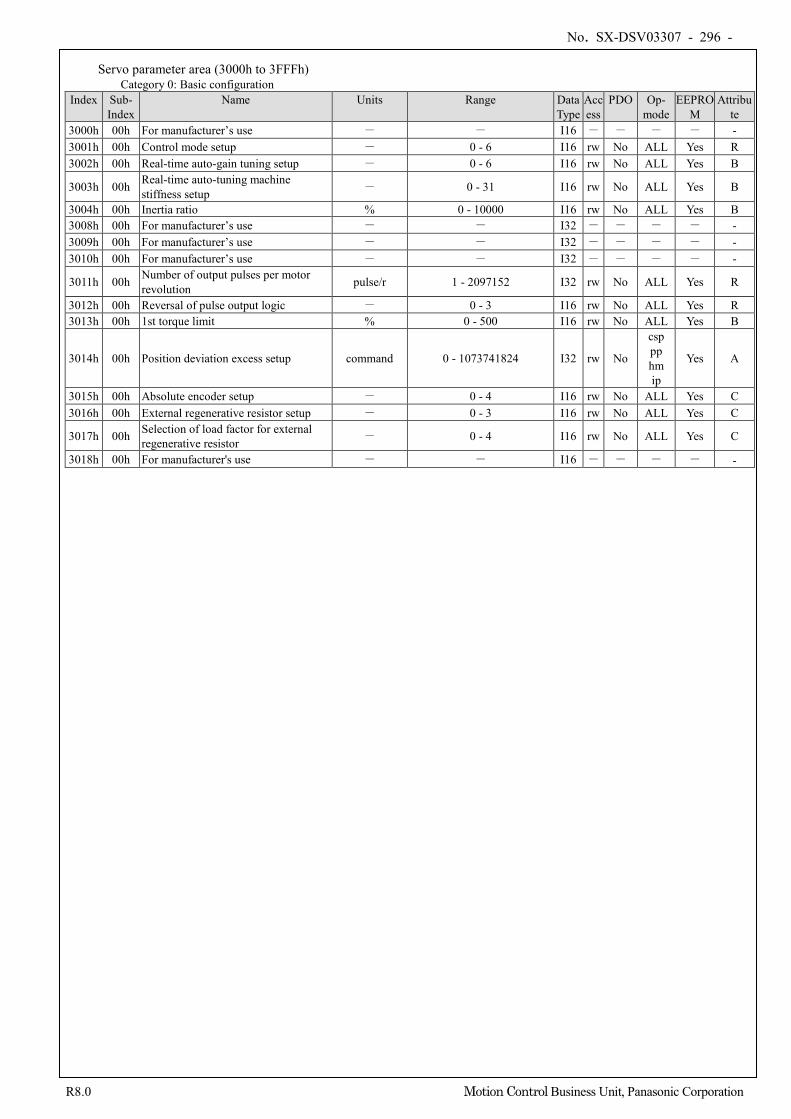
No. SX-DSV03307 - 296 -
R8.0 Motion Control Business Unit, Panasonic Corporation
Servo parameter area (3000h to 3FFFh) Category 0: Basic configuration
Index Sub- Index
Name Units Range Data Type
Access
PDO Op- mode
EEPROM
Attribute
3000h 00h For manufacturer’s use - - I16 - - - - - 3001h 00h Control mode setup - 0 - 6 I16 rw No ALL Yes R 3002h 00h Real-time auto-gain tuning setup - 0 - 6 I16 rw No ALL Yes B
3003h 00h Real-time auto-tuning machine stiffness setup - 0 - 31 I16 rw No ALL Yes B
3004h 00h Inertia ratio % 0 - 10000 I16 rw No ALL Yes B 3008h 00h For manufacturer’s use - - I32 - - - - - 3009h 00h For manufacturer’s use - - I32 - - - - - 3010h 00h For manufacturer’s use - - I32 - - - - -
3011h 00h Number of output pulses per motor revolution pulse/r 1 - 2097152 I32 rw No ALL Yes R
3012h 00h Reversal of pulse output logic - 0 - 3 I16 rw No ALL Yes R 3013h 00h 1st torque limit % 0 - 500 I16 rw No ALL Yes B
3014h 00h Position deviation excess setup command 0 - 1073741824 I32 rw No
csp pp hm ip
Yes A
3015h 00h Absolute encoder setup - 0 - 4 I16 rw No ALL Yes C 3016h 00h External regenerative resistor setup - 0 - 3 I16 rw No ALL Yes C
3017h 00h Selection of load factor for external regenerative resistor - 0 - 4 I16 rw No ALL Yes C
3018h 00h For manufacturer's use - - I16 - - - - -
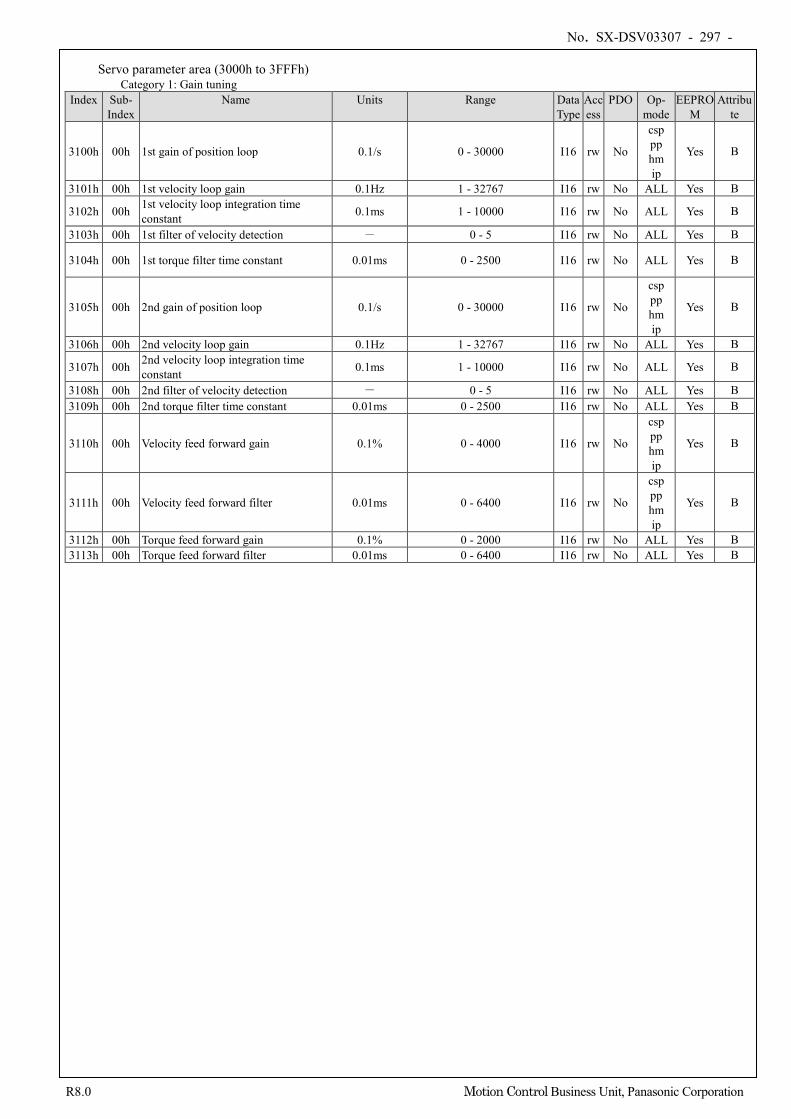
No. SX-DSV03307 - 297 -
R8.0 Motion Control Business Unit, Panasonic Corporation
Servo parameter area (3000h to 3FFFh) Category 1: Gain tuning
Index Sub- Index
Name Units Range Data Type
Access
PDO Op- mode
EEPROM
Attribute
3100h 00h 1st gain of position loop 0.1/s 0 - 30000 I16 rw No
csp pp hm ip
Yes B
3101h 00h 1st velocity loop gain 0.1Hz 1 - 32767 I16 rw No ALL Yes B
3102h 00h 1st velocity loop integration time constant 0.1ms 1 - 10000 I16 rw No ALL Yes B
3103h 00h 1st filter of velocity detection - 0 - 5 I16 rw No ALL Yes B
3104h 00h 1st torque filter time constant 0.01ms 0 - 2500 I16 rw No ALL Yes B
3105h 00h 2nd gain of position loop 0.1/s 0 - 30000 I16 rw No
csp pp hm ip
Yes B
3106h 00h 2nd velocity loop gain 0.1Hz 1 - 32767 I16 rw No ALL Yes B
3107h 00h 2nd velocity loop integration time constant 0.1ms 1 - 10000 I16 rw No ALL Yes B
3108h 00h 2nd filter of velocity detection - 0 - 5 I16 rw No ALL Yes B 3109h 00h 2nd torque filter time constant 0.01ms 0 - 2500 I16 rw No ALL Yes B
3110h 00h Velocity feed forward gain 0.1% 0 - 4000 I16 rw No
csp pp hm ip
Yes B
3111h 00h Velocity feed forward filter 0.01ms 0 - 6400 I16 rw No
csp pp hm ip
Yes B
3112h 00h Torque feed forward gain 0.1% 0 - 2000 I16 rw No ALL Yes B 3113h 00h Torque feed forward filter 0.01ms 0 - 6400 I16 rw No ALL Yes B
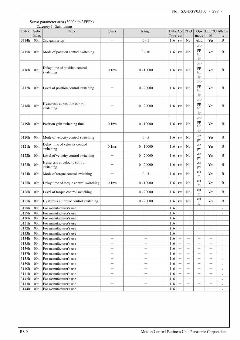
No. SX-DSV03307 - 298 -
R8.0 Motion Control Business Unit, Panasonic Corporation
Servo parameter area (3000h to 3FFFh)
Category 1: Gain tuning Index Sub-
Index Name Units Range Data
Type Access
PDO Op- mode
EEPROM
Attribute
3114h 00h 2nd gain setup - 0 - 1 I16 rw No ALL Yes B
3115h 00h Mode of position control switching - 0 - 10 I16 rw No
csp pp hm ip
Yes B
3116h 00h Delay time of position control switching 0.1ms 0 - 10000 I16 rw No
csp pp hm ip
Yes B
3117h 00h Level of position control switching - 0 - 20000 I16 rw No
csp pp hm ip
Yes B
3118h 00h Hysteresis at position control switching - 0 - 20000 I16 rw No
csp pp hm ip
Yes B
3119h 00h Position gain switching time 0.1ms 0 - 10000 I16 rw No
csp pp hm ip
Yes B
3120h 00h Mode of velocity control switching - 0 - 5 I16 rw No csv pv Yes B
3121h 00h Delay time of velocity control switching 0.1ms 0 - 10000 I16 rw No csv
pv Yes B
3122h 00h Level of velocity control switching - 0 - 20000 I16 rw No csv pv Yes B
3123h 00h Hysteresis at velocity control switching - 0 - 20000 I16 rw No csv
pv Yes B
3124h 00h Mode of torque control switching - 0 - 3 I16 rw No cst tq Yes B
3125h 00h Delay time of torque control switching 0.1ms 0 - 10000 I16 rw No cst tq Yes B
3126h 00h Level of torque control switching - 0 - 20000 I16 rw No cst tq Yes B
3127h 00h Hysteresis at torque control switching - 0 - 20000 I16 rw No cst tq Yes B
3128h 00h For manufacturer's use - - I16 - - - - - 3129h 00h For manufacturer's use - - I16 - - - - - 3130h 00h For manufacturer's use - - I16 - - - - - 3131h 00h For manufacturer's use - - I16 - - - - - 3132h 00h For manufacturer's use - - I16 - - - - - 3133h 00h For manufacturer's use - - I16 - - - - - 3134h 00h For manufacturer's use - - I16 - - - - - 3135h 00h For manufacturer's use - - I16 - - - - - 3136h 00h For manufacturer's use - - I16 - - - - - 3137h 00h For manufacturer's use - - I16 - - - - - 3138h 00h For manufacturer's use - - I16 - - - - - 3139h 00h For manufacturer's use - - I16 - - - - - 3140h 00h For manufacturer's use - - I16 - - - - - 3141h 00h For manufacturer's use - - I16 - - - - - 3142h 00h For manufacturer's use - - I16 - - - - - 3143h 00h For manufacturer's use - - I16 - - - - - 3144h 00h For manufacturer's use - - I16 - - - - -
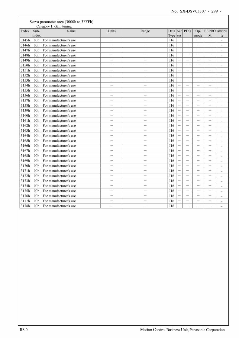
No. SX-DSV03307 - 299 -
R8.0 Motion Control Business Unit, Panasonic Corporation
Servo parameter area (3000h to 3FFFh)
Category 1: Gain tuning Index Sub-
Index Name Units Range Data
Type Access
PDO Op- mode
EEPROM
Attribute
3145h 00h For manufacturer's use - - I16 - - - - - 3146h 00h For manufacturer's use - - I16 - - - - - 3147h 00h For manufacturer's use - - I16 - - - - - 3148h 00h For manufacturer's use - - I16 - - - - - 3149h 00h For manufacturer's use - - I16 - - - - - 3150h 00h For manufacturer's use - - I16 - - - - - 3151h 00h For manufacturer's use - - I16 - - - - - 3152h 00h For manufacturer's use - - I16 - - - - - 3153h 00h For manufacturer's use - - I16 - - - - - 3154h 00h For manufacturer's use - - I16 - - - - - 3155h 00h For manufacturer's use - - I16 - - - - - 3156h 00h For manufacturer's use - - I16 - - - - - 3157h 00h For manufacturer's use - - I16 - - - - - 3158h 00h For manufacturer's use - - I16 - - - - - 3159h 00h For manufacturer's use - - I16 - - - - - 3160h 00h For manufacturer's use - - I16 - - - - - 3161h 00h For manufacturer's use - - I16 - - - - - 3162h 00h For manufacturer's use - - I16 - - - - - 3163h 00h For manufacturer's use - - I16 - - - - - 3164h 00h For manufacturer's use - - I16 - - - - - 3165h 00h For manufacturer's use - - I16 - - - - - 3166h 00h For manufacturer's use - - I16 - - - - - 3167h 00h For manufacturer's use - - I16 - - - - - 3168h 00h For manufacturer's use - - I16 - - - - - 3169h 00h For manufacturer's use - - I16 - - - - - 3170h 00h For manufacturer's use - - I16 - - - - - 3171h 00h For manufacturer's use - - I16 - - - - - 3172h 00h For manufacturer's use - - I16 - - - - - 3173h 00h For manufacturer's use - - I16 - - - - - 3174h 00h For manufacturer's use - - I16 - - - - - 3175h 00h For manufacturer's use - - I16 - - - - - 3176h 00h For manufacturer's use - - I16 - - - - - 3177h 00h For manufacturer's use - - I16 - - - - - 3178h 00h For manufacturer's use - - I16 - - - - -
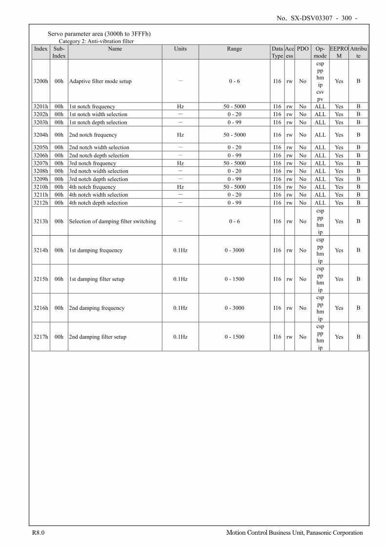
No. SX-DSV03307 - 300 -
R8.0 Motion Control Business Unit, Panasonic Corporation
Servo parameter area (3000h to 3FFFh) Category 2: Anti-vibration filter
Index Sub- Index
Name Units Range Data Type
Access
PDO Op- mode
EEPROM
Attribute
3200h 00h Adaptive filter mode setup - 0 - 6 I16 rw No
csp pp hm ip
csv pv
Yes B
3201h 00h 1st notch frequency Hz 50 - 5000 I16 rw No ALL Yes B 3202h 00h 1st notch width selection - 0 - 20 I16 rw No ALL Yes B 3203h 00h 1st notch depth selection - 0 - 99 I16 rw No ALL Yes B
3204h 00h 2nd notch frequency Hz 50 - 5000 I16 rw No ALL Yes B
3205h 00h 2nd notch width selection - 0 - 20 I16 rw No ALL Yes B 3206h 00h 2nd notch depth selection - 0 - 99 I16 rw No ALL Yes B 3207h 00h 3rd notch frequency Hz 50 - 5000 I16 rw No ALL Yes B 3208h 00h 3rd notch width selection - 0 - 20 I16 rw No ALL Yes B 3209h 00h 3rd notch depth selection - 0 - 99 I16 rw No ALL Yes B 3210h 00h 4th notch frequency Hz 50 - 5000 I16 rw No ALL Yes B 3211h 00h 4th notch width selection - 0 - 20 I16 rw No ALL Yes B 3212h 00h 4th notch depth selection - 0 - 99 I16 rw No ALL Yes B
3213h 00h Selection of damping filter switching - 0 - 6 I16 rw No
csp pp hm ip
Yes B
3214h 00h 1st damping frequency 0.1Hz 0 - 3000 I16 rw No
csp pp hm ip
Yes B
3215h 00h 1st damping filter setup 0.1Hz 0 - 1500 I16 rw No
csp pp hm ip
Yes B
3216h 00h 2nd damping frequency 0.1Hz 0 - 3000 I16 rw No
csp pp hm ip
Yes B
3217h 00h 2nd damping filter setup 0.1Hz 0 - 1500 I16 rw No
csp pp hm ip
Yes B
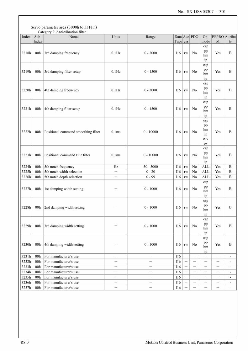
No. SX-DSV03307 - 301 -
R8.0 Motion Control Business Unit, Panasonic Corporation
Servo parameter area (3000h to 3FFFh) Category 2: Anti-vibration filter
Index Sub- Index
Name Units Range Data Type
Access
PDO Op- mode
EEPROM
Attribute
3218h 00h 3rd damping frequency 0.1Hz 0 - 3000 I16 rw No
csp pp hm ip
Yes B
3219h 00h 3rd damping filter setup 0.1Hz 0 - 1500 I16 rw No
csp pp hm ip
Yes B
3220h 00h 4th damping frequency 0.1Hz 0 - 3000 I16 rw No
csp pp hm ip
Yes B
3221h 00h 4th damping filter setup 0.1Hz 0 - 1500 I16 rw No
csp pp hm ip
Yes B
3222h 00h Positional command smoothing filter 0.1ms 0 - 10000 I16 rw No
csp pp hm ip
csv pv
Yes B
3223h 00h Positional command FIR filter 0.1ms 0 - 10000 I16 rw No
csp pp hm ip
Yes B
3224h 00h 5th notch frequency Hz 50 - 5000 I16 rw No ALL Yes B 3225h 00h 5th notch width selection - 0 - 20 I16 rw No ALL Yes B 3226h 00h 5th notch depth selection - 0 - 99 I16 rw No ALL Yes B
3227h 00h 1st damping width setting - 0 - 1000 I16 rw No
csp pp hm ip
Yes B
3228h 00h 2nd damping width setting - 0 - 1000 I16 rw No
csp pp hm ip
Yes B
3229h 00h 3rd damping width setting - 0 - 1000 I16 rw No
csp pp hm ip
Yes B
3230h 00h 4th damping width setting - 0 - 1000 I16 rw No
csp pp hm ip
Yes B
3231h 00h For manufacturer's use - - I16 - - - - - 3232h 00h For manufacturer's use - - I16 - - - - - 3233h 00h For manufacturer's use - - I16 - - - - - 3234h 00h For manufacturer's use - - I16 - - - - - 3235h 00h For manufacturer's use - - I16 - - - - - 3236h 00h For manufacturer's use - - I16 - - - - - 3237h 00h For manufacturer's use - - I16 - - - - -
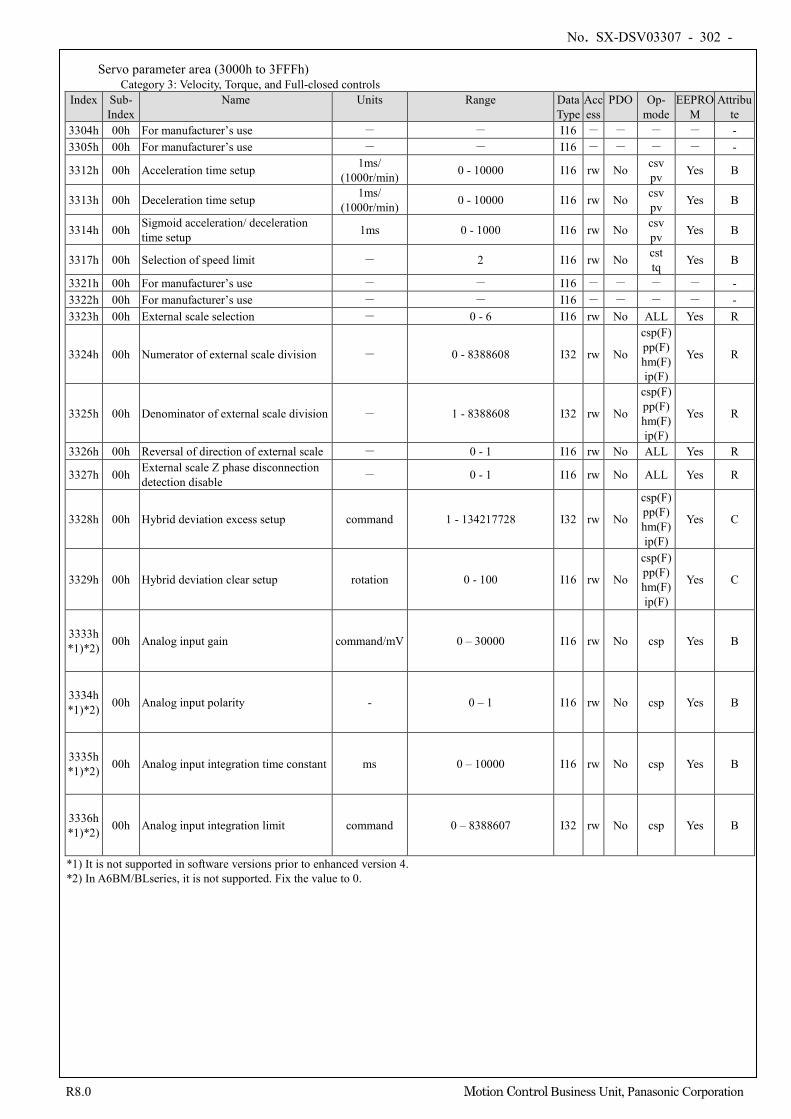
No. SX-DSV03307 - 302 -
R8.0 Motion Control Business Unit, Panasonic Corporation
Servo parameter area (3000h to 3FFFh) Category 3: Velocity, Torque, and Full-closed controls
Index Sub- Index
Name Units Range Data Type
Access
PDO Op- mode
EEPROM
Attribute
3304h 00h For manufacturer’s use - - I16 - - - - - 3305h 00h For manufacturer’s use - - I16 - - - - -
3312h 00h Acceleration time setup 1ms/ (1000r/min) 0 - 10000 I16 rw No csv
pv Yes B
3313h 00h Deceleration time setup 1ms/ (1000r/min) 0 - 10000 I16 rw No csv
pv Yes B
3314h 00h Sigmoid acceleration/ deceleration time setup 1ms 0 - 1000 I16 rw No csv
pv Yes B
3317h 00h Selection of speed limit - 2 I16 rw No cst tq Yes B
3321h 00h For manufacturer’s use - - I16 - - - - - 3322h 00h For manufacturer’s use - - I16 - - - - - 3323h 00h External scale selection - 0 - 6 I16 rw No ALL Yes R
3324h 00h Numerator of external scale division - 0 - 8388608 I32 rw No
csp(F) pp(F) hm(F) ip(F)
Yes R
3325h 00h Denominator of external scale division - 1 - 8388608 I32 rw No
csp(F) pp(F) hm(F) ip(F)
Yes R
3326h 00h Reversal of direction of external scale - 0 - 1 I16 rw No ALL Yes R
3327h 00h External scale Z phase disconnection detection disable - 0 - 1 I16 rw No ALL Yes R
3328h 00h Hybrid deviation excess setup command 1 - 134217728 I32 rw No
csp(F) pp(F) hm(F) ip(F)
Yes C
3329h 00h Hybrid deviation clear setup rotation 0 - 100 I16 rw No
csp(F) pp(F) hm(F) ip(F)
Yes C
3333h *1)*2) 00h Analog input gain command/mV 0 – 30000 I16 rw No csp Yes B
3334h *1)*2) 00h Analog input polarity - 0 – 1 I16 rw No csp Yes B
3335h *1)*2) 00h Analog input integration time constant ms 0 – 10000 I16 rw No csp Yes B
3336h *1)*2) 00h Analog input integration limit command 0 – 8388607 I32 rw No csp Yes B
*1) It is not supported in software versions prior to enhanced version 4. *2) In A6BM/BLseries, it is not supported. Fix the value to 0.
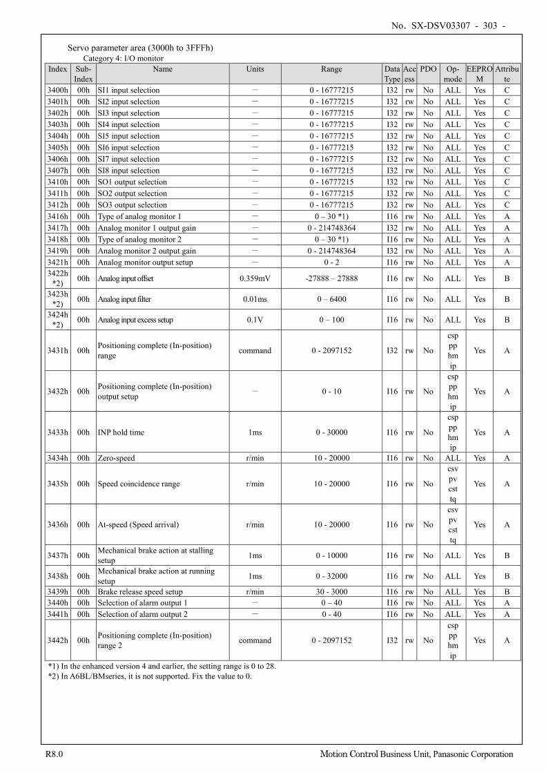
No. SX-DSV03307 - 303 -
R8.0 Motion Control Business Unit, Panasonic Corporation
Servo parameter area (3000h to 3FFFh) Category 4: I/O monitor
Index Sub- Index
Name Units Range Data Type
Access
PDO Op- mode
EEPROM
Attribute
3400h 00h SI1 input selection - 0 - 16777215 I32 rw No ALL Yes C 3401h 00h SI2 input selection - 0 - 16777215 I32 rw No ALL Yes C 3402h 00h SI3 input selection - 0 - 16777215 I32 rw No ALL Yes C 3403h 00h SI4 input selection - 0 - 16777215 I32 rw No ALL Yes C 3404h 00h SI5 input selection - 0 - 16777215 I32 rw No ALL Yes C 3405h 00h SI6 input selection - 0 - 16777215 I32 rw No ALL Yes C 3406h 00h SI7 input selection - 0 - 16777215 I32 rw No ALL Yes C 3407h 00h SI8 input selection - 0 - 16777215 I32 rw No ALL Yes C 3410h 00h SO1 output selection - 0 - 16777215 I32 rw No ALL Yes C 3411h 00h SO2 output selection - 0 - 16777215 I32 rw No ALL Yes C 3412h 00h SO3 output selection - 0 - 16777215 I32 rw No ALL Yes C 3416h 00h Type of analog monitor 1 - 0 – 30 *1) I16 rw No ALL Yes A 3417h 00h Analog monitor 1 output gain - 0 - 214748364 I32 rw No ALL Yes A 3418h 00h Type of analog monitor 2 - 0 – 30 *1) I16 rw No ALL Yes A 3419h 00h Analog monitor 2 output gain - 0 - 214748364 I32 rw No ALL Yes A 3421h 00h Analog monitor output setup - 0 - 2 I16 rw No ALL Yes A 3422h
*2) 00h Analog input offset 0.359mV -27888 – 27888 I16 rw No ALL Yes B
3423h *2) 00h Analog input filter 0.01ms 0 – 6400 I16 rw No ALL Yes B
3424h *2) 00h Analog input excess setup 0.1V 0 – 100 I16 rw No ALL Yes B
3431h 00h Positioning complete (In-position) range command 0 - 2097152 I32 rw No
csp pp hm ip
Yes A
3432h 00h Positioning complete (In-position) output setup - 0 - 10 I16 rw No
csp pp hm ip
Yes A
3433h 00h INP hold time 1ms 0 - 30000 I16 rw No
csp pp hm ip
Yes A
3434h 00h Zero-speed r/min 10 - 20000 I16 rw No ALL Yes A
3435h 00h Speed coincidence range r/min 10 - 20000 I16 rw No
csv pv cst tq
Yes A
3436h 00h At-speed (Speed arrival) r/min 10 - 20000 I16 rw No
csv pv cst tq
Yes A
3437h 00h Mechanical brake action at stalling setup 1ms 0 - 10000 I16 rw No ALL Yes B
3438h 00h Mechanical brake action at running setup 1ms 0 - 32000 I16 rw No ALL Yes B
3439h 00h Brake release speed setup r/min 30 - 3000 I16 rw No ALL Yes B 3440h 00h Selection of alarm output 1 - 0 – 40 I16 rw No ALL Yes A 3441h 00h Selection of alarm output 2 - 0 - 40 I16 rw No ALL Yes A
3442h 00h Positioning complete (In-position) range 2 command 0 - 2097152 I32 rw No
csp pp hm ip
Yes A
*1) In the enhanced version 4 and earlier, the setting range is 0 to 28. *2) In A6BL/BMseries, it is not supported. Fix the value to 0.
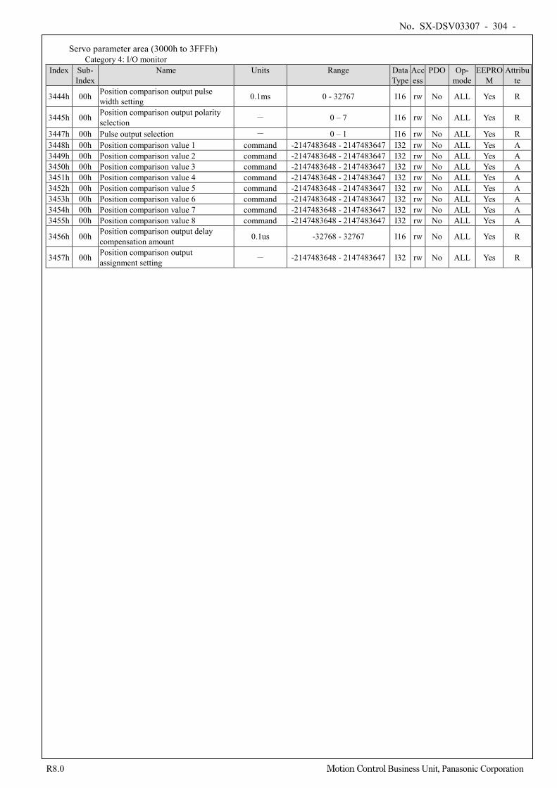
No. SX-DSV03307 - 304 -
R8.0 Motion Control Business Unit, Panasonic Corporation
Servo parameter area (3000h to 3FFFh) Category 4: I/O monitor
Index Sub- Index
Name Units Range Data Type
Access
PDO Op- mode
EEPROM
Attribute
3444h 00h Position comparison output pulse width setting 0.1ms 0 - 32767 I16 rw No ALL Yes R
3445h 00h Position comparison output polarity selection - 0 – 7 I16 rw No ALL Yes R
3447h 00h Pulse output selection - 0 – 1 I16 rw No ALL Yes R 3448h 00h Position comparison value 1 command -2147483648 - 2147483647 I32 rw No ALL Yes A 3449h 00h Position comparison value 2 command -2147483648 - 2147483647 I32 rw No ALL Yes A 3450h 00h Position comparison value 3 command -2147483648 - 2147483647 I32 rw No ALL Yes A 3451h 00h Position comparison value 4 command -2147483648 - 2147483647 I32 rw No ALL Yes A 3452h 00h Position comparison value 5 command -2147483648 - 2147483647 I32 rw No ALL Yes A 3453h 00h Position comparison value 6 command -2147483648 - 2147483647 I32 rw No ALL Yes A 3454h 00h Position comparison value 7 command -2147483648 - 2147483647 I32 rw No ALL Yes A 3455h 00h Position comparison value 8 command -2147483648 - 2147483647 I32 rw No ALL Yes A
3456h 00h Position comparison output delay compensation amount 0.1us -32768 - 32767 I16 rw No ALL Yes R
3457h 00h Position comparison output assignment setting - -2147483648 - 2147483647 I32 rw No ALL Yes R
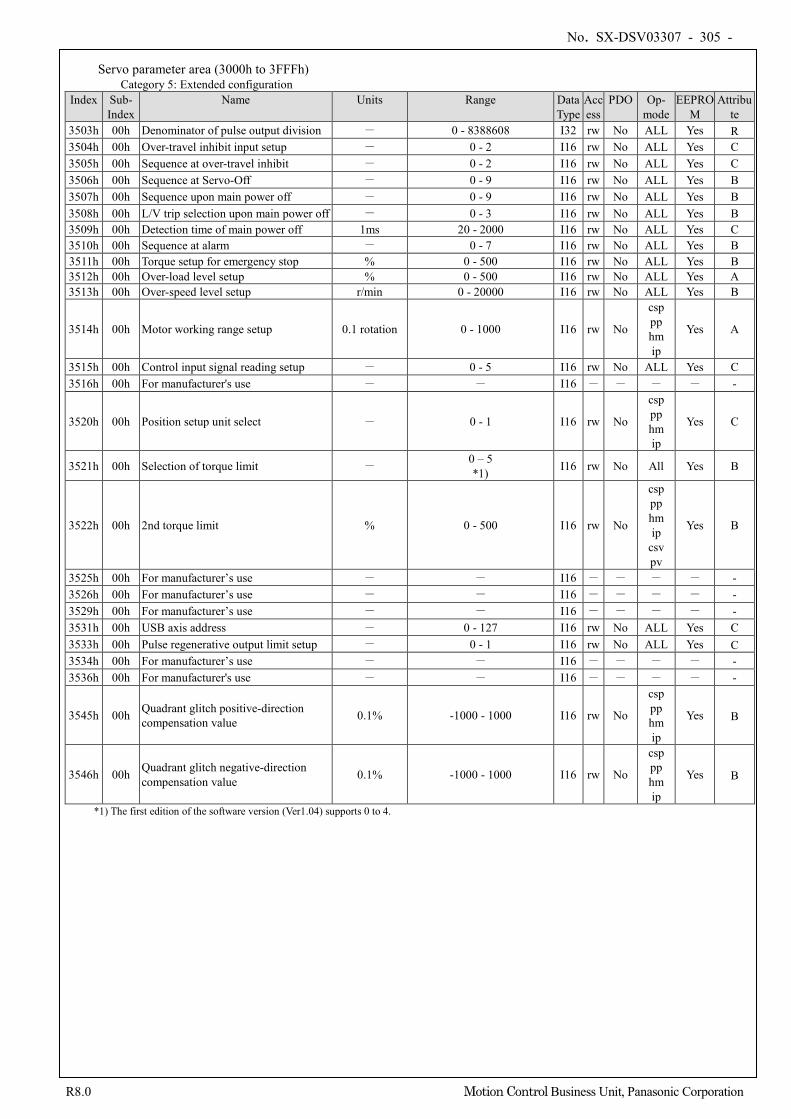
No. SX-DSV03307 - 305 -
R8.0 Motion Control Business Unit, Panasonic Corporation
Servo parameter area (3000h to 3FFFh) Category 5: Extended configuration
Index Sub- Index
Name Units Range Data Type
Access
PDO Op- mode
EEPROM
Attribute
3503h 00h Denominator of pulse output division - 0 - 8388608 I32 rw No ALL Yes R 3504h 00h Over-travel inhibit input setup - 0 - 2 I16 rw No ALL Yes C 3505h 00h Sequence at over-travel inhibit - 0 - 2 I16 rw No ALL Yes C 3506h 00h Sequence at Servo-Off - 0 - 9 I16 rw No ALL Yes B 3507h 00h Sequence upon main power off - 0 - 9 I16 rw No ALL Yes B 3508h 00h L/V trip selection upon main power off - 0 - 3 I16 rw No ALL Yes B 3509h 00h Detection time of main power off 1ms 20 - 2000 I16 rw No ALL Yes C 3510h 00h Sequence at alarm - 0 - 7 I16 rw No ALL Yes B 3511h 00h Torque setup for emergency stop % 0 - 500 I16 rw No ALL Yes B 3512h 00h Over-load level setup % 0 - 500 I16 rw No ALL Yes A 3513h 00h Over-speed level setup r/min 0 - 20000 I16 rw No ALL Yes B
3514h 00h Motor working range setup 0.1 rotation 0 - 1000 I16 rw No
csp pp hm ip
Yes A
3515h 00h Control input signal reading setup - 0 - 5 I16 rw No ALL Yes C 3516h 00h For manufacturer's use - - I16 - - - - -
3520h 00h Position setup unit select - 0 - 1 I16 rw No
csp pp hm ip
Yes C
3521h 00h Selection of torque limit - 0 – 5 *1) I16 rw No All Yes B
3522h 00h 2nd torque limit % 0 - 500 I16 rw No
csp pp hm ip
csv pv
Yes B
3525h 00h For manufacturer’s use - - I16 - - - - - 3526h 00h For manufacturer’s use - - I16 - - - - - 3529h 00h For manufacturer’s use - - I16 - - - - - 3531h 00h USB axis address - 0 - 127 I16 rw No ALL Yes C 3533h 00h Pulse regenerative output limit setup - 0 - 1 I16 rw No ALL Yes C 3534h 00h For manufacturer’s use - - I16 - - - - - 3536h 00h For manufacturer's use - - I16 - - - - -
3545h 00h Quadrant glitch positive-direction compensation value 0.1% -1000 - 1000 I16 rw No
csp pp hm ip
Yes B
3546h 00h Quadrant glitch negative-direction compensation value 0.1% -1000 - 1000 I16 rw No
csp pp hm ip
Yes B
*1) The first edition of the software version (Ver1.04) supports 0 to 4.
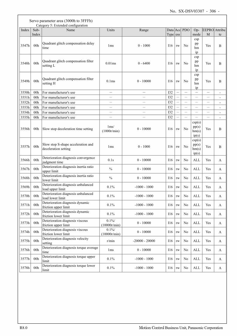
No. SX-DSV03307 - 306 -
R8.0 Motion Control Business Unit, Panasonic Corporation
Servo parameter area (3000h to 3FFFh) Category 5: Extended configuration
Index Sub- Index
Name Units Range Data Type
Access
PDO Op- mode
EEPROM
Attribute
3547h 00h Quadrant glitch compensation delay time 1ms 0 - 1000 I16 rw No
csp pp hm ip
Yes B
3548h 00h Quadrant glitch compensation filter setting L 0.01ms 0 - 6400 I16 rw No
csp pp hm ip
Yes B
3549h 00h Quadrant glitch compensation filter setting H 0.1ms 0 - 10000 I16 rw No
csp pp hm ip
Yes B
3550h 00h For manufacturer's use - - I32 - - - - - 3551h 00h For manufacturer's use - - I32 - - - - - 3552h 00h For manufacturer's use - - I32 - - - - - 3553h 00h For manufacturer's use - - I32 - - - - - 3554h 00h For manufacturer's use - - I32 - - - - - 3555h 00h For manufacturer's use - - I32 - - - - -
3556h 00h Slow stop deceleration time setting 1ms/ (1000r/min) 0 - 10000 I16 rw No
csp(s) pp(s) hm(s) ip(s)
Yes B
3557h 00h Slow stop S-shape acceleration and deceleration setting 1ms 0 - 1000 I16 rw No
csp(s) pp(s) hm(s) ip(s)
Yes B
3566h 00h Deterioration diagnosis convergence judgment time 0.1s 0 - 10000 I16 rw No ALL Yes A
3567h 00h Deterioration diagnosis inertia ratio upper limit % 0 - 10000 I16 rw No ALL Yes A
3568h 00h Deterioration diagnosis inertia ratio lower limit % 0 - 10000 I16 rw No ALL Yes A
3569h 00h Deterioration diagnosis unbalanced load upper limit 0.1% -1000 - 1000 I16 rw No ALL Yes A
3570h 00h Deterioration diagnosis unbalanced load lower limit 0.1% -1000 - 1000 I16 rw No ALL Yes A
3571h 00h Deterioration diagnosis dynamic friction upper limit 0.1% -1000 - 1000 I16 rw No ALL Yes A
3572h 00h Deterioration diagnosis dynamic friction lower limit 0.1% -1000 - 1000 I16 rw No ALL Yes A
3573h 00h Deterioration diagnosis viscous friction upper limit
0.1%/ (10000r/min) 0 - 10000 I16 rw No ALL Yes A
3574h 00h Deterioration diagnosis viscous friction lower limit
0.1%/ (10000r/min) 0 - 10000 I16 rw No ALL Yes A
3575h 00h Deterioration diagnosis velocity setting r/min -20000 - 20000 I16 rw No ALL Yes A
3576h 00h Deterioration diagnosis torque average time 1ms 0 - 10000 I16 rw No ALL Yes A
3577h 00h Deterioration diagnosis torque upper limit 0.1% -1000 - 1000 I16 rw No ALL Yes A
3578h 00h Deterioration diagnosis torque lower limit 0.1% -1000 - 1000 I16 rw No ALL Yes A
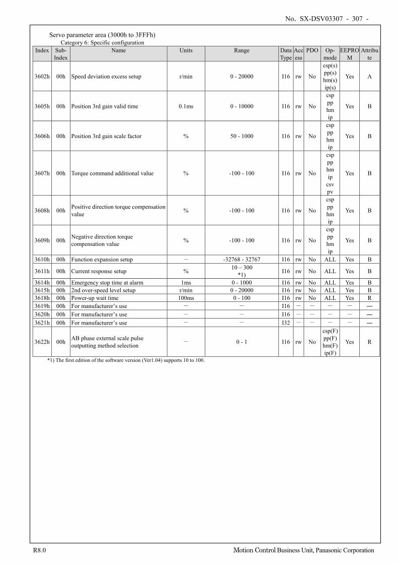
No. SX-DSV03307 - 307 -
R8.0 Motion Control Business Unit, Panasonic Corporation
Servo parameter area (3000h to 3FFFh) Category 6: Specific configuration
Index Sub- Index
Name Units Range Data Type
Access
PDO Op- mode
EEPROM
Attribute
3602h 00h Speed deviation excess setup r/min 0 - 20000 I16 rw No
csp(s) pp(s) hm(s) ip(s)
Yes A
3605h 00h Position 3rd gain valid time 0.1ms 0 - 10000 I16 rw No
csp pp hm ip
Yes B
3606h 00h Position 3rd gain scale factor % 50 - 1000 I16 rw No
csp pp hm ip
Yes B
3607h 00h Torque command additional value % -100 - 100 I16 rw No
csp pp hm ip
csv pv
Yes B
3608h 00h Positive direction torque compensation value % -100 - 100 I16 rw No
csp pp hm ip
Yes B
3609h 00h Negative direction torque compensation value % -100 - 100 I16 rw No
csp pp hm ip
Yes B
3610h 00h Function expansion setup - -32768 - 32767 I16 rw No ALL Yes B
3611h 00h Current response setup % 10 – 300 *1) I16 rw No ALL Yes B
3614h 00h Emergency stop time at alarm 1ms 0 - 1000 I16 rw No ALL Yes B 3615h 00h 2nd over-speed level setup r/min 0 - 20000 I16 rw No ALL Yes B 3618h 00h Power-up wait time 100ms 0 - 100 I16 rw No ALL Yes R 3619h 00h For manufacturer’s use - - I16 - - - - ― 3620h 00h For manufacturer’s use - - I16 - - - - ― 3621h 00h For manufacturer’s use - - I32 - - - - ―
3622h 00h AB phase external scale pulse outputting method selection - 0 - 1 I16 rw No
csp(F) pp(F) hm(F) ip(F)
Yes R
*1) The first edition of the software version (Ver1.04) supports 10 to 100.
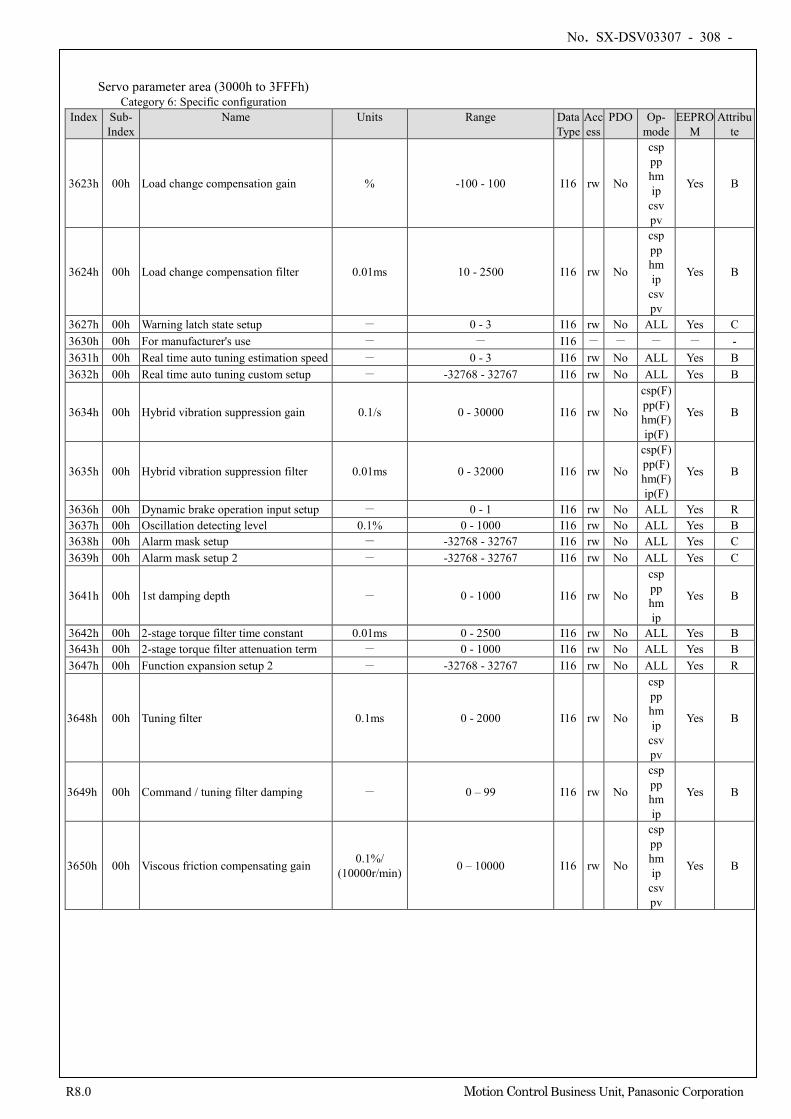
No. SX-DSV03307 - 308 -
R8.0 Motion Control Business Unit, Panasonic Corporation
Servo parameter area (3000h to 3FFFh) Category 6: Specific configuration
Index Sub- Index
Name Units Range Data Type
Access
PDO Op- mode
EEPROM
Attribute
3623h 00h Load change compensation gain % -100 - 100 I16 rw No
csp pp hm ip
csv pv
Yes B
3624h 00h Load change compensation filter 0.01ms 10 - 2500 I16 rw No
csp pp hm ip
csv pv
Yes B
3627h 00h Warning latch state setup - 0 - 3 I16 rw No ALL Yes C 3630h 00h For manufacturer's use - - I16 - - - - - 3631h 00h Real time auto tuning estimation speed - 0 - 3 I16 rw No ALL Yes B 3632h 00h Real time auto tuning custom setup - -32768 - 32767 I16 rw No ALL Yes B
3634h 00h Hybrid vibration suppression gain 0.1/s 0 - 30000 I16 rw No
csp(F) pp(F) hm(F) ip(F)
Yes B
3635h 00h Hybrid vibration suppression filter 0.01ms 0 - 32000 I16 rw No
csp(F) pp(F) hm(F) ip(F)
Yes B
3636h 00h Dynamic brake operation input setup - 0 - 1 I16 rw No ALL Yes R 3637h 00h Oscillation detecting level 0.1% 0 - 1000 I16 rw No ALL Yes B 3638h 00h Alarm mask setup - -32768 - 32767 I16 rw No ALL Yes C 3639h 00h Alarm mask setup 2 - -32768 - 32767 I16 rw No ALL Yes C
3641h 00h 1st damping depth - 0 - 1000 I16 rw No
csp pp hm ip
Yes B
3642h 00h 2-stage torque filter time constant 0.01ms 0 - 2500 I16 rw No ALL Yes B 3643h 00h 2-stage torque filter attenuation term - 0 - 1000 I16 rw No ALL Yes B 3647h 00h Function expansion setup 2 - -32768 - 32767 I16 rw No ALL Yes R
3648h 00h Tuning filter 0.1ms 0 - 2000 I16 rw No
csp pp hm ip
csv pv
Yes B
3649h 00h Command / tuning filter damping - 0 – 99 I16 rw No
csp pp hm ip
Yes B
3650h 00h Viscous friction compensating gain 0.1%/ (10000r/min) 0 – 10000 I16 rw No
csp pp hm ip
csv pv
Yes B
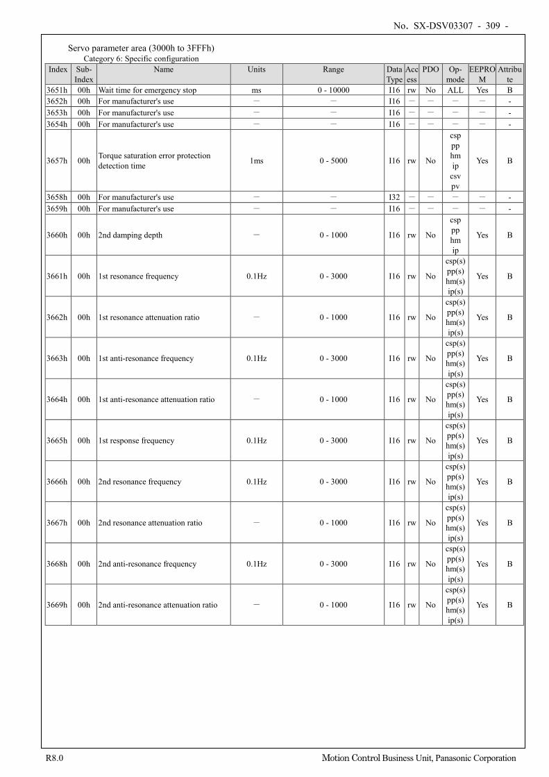
No. SX-DSV03307 - 309 -
R8.0 Motion Control Business Unit, Panasonic Corporation
Servo parameter area (3000h to 3FFFh) Category 6: Specific configuration
Index Sub- Index
Name Units Range Data Type
Access
PDO Op- mode
EEPROM
Attribute
3651h 00h Wait time for emergency stop ms 0 - 10000 I16 rw No ALL Yes B 3652h 00h For manufacturer's use - - I16 - - - - - 3653h 00h For manufacturer's use - - I16 - - - - - 3654h 00h For manufacturer's use - - I16 - - - - -
3657h 00h Torque saturation error protection detection time 1ms 0 - 5000 I16 rw No
csp pp hm ip
csv pv
Yes B
3658h 00h For manufacturer's use - - I32 - - - - - 3659h 00h For manufacturer's use - - I16 - - - - -
3660h 00h 2nd damping depth - 0 - 1000 I16 rw No
csp pp hm ip
Yes B
3661h 00h 1st resonance frequency 0.1Hz 0 - 3000 I16 rw No
csp(s) pp(s) hm(s) ip(s)
Yes B
3662h 00h 1st resonance attenuation ratio - 0 - 1000 I16 rw No
csp(s) pp(s) hm(s) ip(s)
Yes B
3663h 00h 1st anti-resonance frequency 0.1Hz 0 - 3000 I16 rw No
csp(s) pp(s) hm(s) ip(s)
Yes B
3664h 00h 1st anti-resonance attenuation ratio - 0 - 1000 I16 rw No
csp(s) pp(s) hm(s) ip(s)
Yes B
3665h 00h 1st response frequency 0.1Hz 0 - 3000 I16 rw No
csp(s) pp(s) hm(s) ip(s)
Yes B
3666h 00h 2nd resonance frequency 0.1Hz 0 - 3000 I16 rw No
csp(s) pp(s) hm(s) ip(s)
Yes B
3667h 00h 2nd resonance attenuation ratio - 0 - 1000 I16 rw No
csp(s) pp(s) hm(s) ip(s)
Yes B
3668h 00h 2nd anti-resonance frequency 0.1Hz 0 - 3000 I16 rw No
csp(s) pp(s) hm(s) ip(s)
Yes B
3669h 00h 2nd anti-resonance attenuation ratio - 0 - 1000 I16 rw No
csp(s) pp(s) hm(s) ip(s)
Yes B
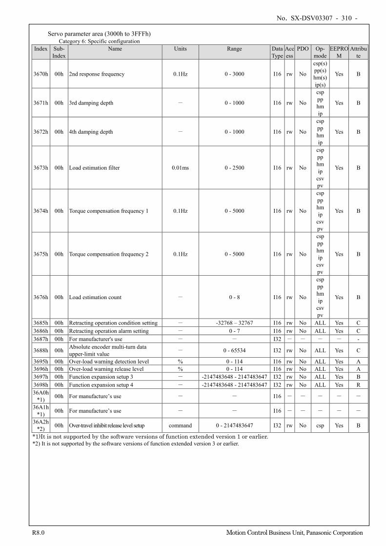
No. SX-DSV03307 - 310 -
R8.0 Motion Control Business Unit, Panasonic Corporation
Servo parameter area (3000h to 3FFFh) Category 6: Specific configuration
Index Sub- Index
Name Units Range Data Type
Access
PDO Op- mode
EEPROM
Attribute
3670h 00h 2nd response frequency 0.1Hz 0 - 3000 I16 rw No
csp(s) pp(s) hm(s) ip(s)
Yes B
3671h 00h 3rd damping depth - 0 - 1000 I16 rw No
csp pp hm ip
Yes B
3672h 00h 4th damping depth - 0 - 1000 I16 rw No
csp pp hm ip
Yes B
3673h 00h Load estimation filter 0.01ms 0 - 2500 I16 rw No
csp pp hm ip
csv pv
Yes B
3674h 00h Torque compensation frequency 1 0.1Hz 0 - 5000 I16 rw No
csp pp hm ip
csv pv
Yes B
3675h 00h Torque compensation frequency 2 0.1Hz 0 - 5000 I16 rw No
csp pp hm ip
csv pv
Yes B
3676h 00h Load estimation count - 0 - 8 I16 rw No
csp pp hm ip
csv pv
Yes B
3685h 00h Retracting operation condition setting - -32768 – 32767 I16 rw No ALL Yes C 3686h 00h Retracting operation alarm setting - 0 - 7 I16 rw No ALL Yes C 3687h 00h For manufacturer's use - - I32 - - - - -
3688h 00h Absolute encoder multi-turn data upper-limit value - 0 - 65534 I32 rw No ALL Yes C
3695h 00h Over-load warning detection level % 0 - 114 I16 rw No ALL Yes A 3696h 00h Over-load warning release level % 0 - 114 I16 rw No ALL Yes A 3697h 00h Function expansion setup 3 - -2147483648 - 2147483647 I32 rw No ALL Yes B 3698h 00h Function expansion setup 4 - -2147483648 - 2147483647 I32 rw No ALL Yes R 36A0h
*1) 00h For manufacture’s use - - I16 - - - - -
36A1h *1) 00h For manufacture’s use - - I16 - - - - -
36A2h *2) 00h Over-travel inhibit release level setup command 0 - 2147483647 I32 rw No csp Yes B
*1)It is not supported by the software versions of function extended version 1 or earlier. *2) It is not supported by the software versions of function extended version 3 or earlier.
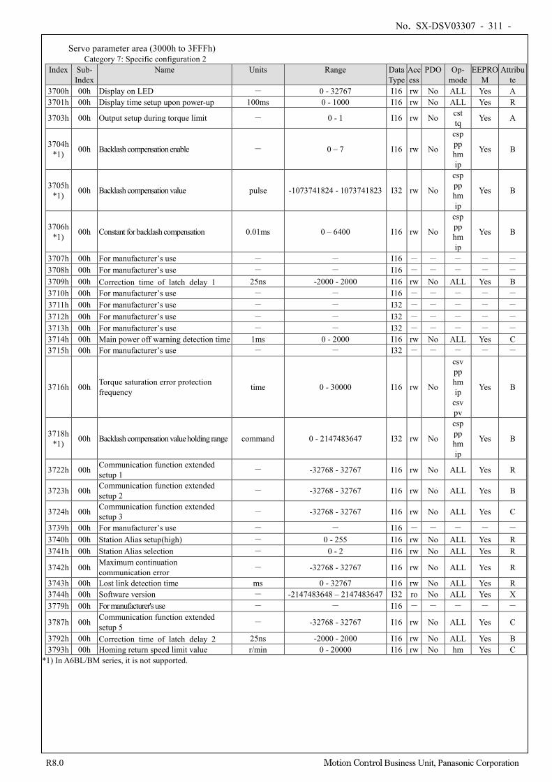
No. SX-DSV03307 - 311 -
R8.0 Motion Control Business Unit, Panasonic Corporation
Servo parameter area (3000h to 3FFFh) Category 7: Specific configuration 2
Index Sub- Index
Name Units Range Data Type
Access
PDO Op- mode
EEPROM
Attribute
3700h 00h Display on LED - 0 - 32767 I16 rw No ALL Yes A 3701h 00h Display time setup upon power-up 100ms 0 - 1000 I16 rw No ALL Yes R
3703h 00h Output setup during torque limit - 0 - 1 I16 rw No cst tq Yes A
3704h *1) 00h Backlash compensation enable - 0 – 7 I16 rw No
csp pp hm ip
Yes B
3705h *1) 00h Backlash compensation value pulse -1073741824 - 1073741823 I32 rw No
csp pp hm ip
Yes B
3706h *1) 00h Constant for backlash compensation 0.01ms 0 – 6400 I16 rw No
csp pp hm ip
Yes B
3707h 00h For manufacturer’s use - - I16 - - - - - 3708h 00h For manufacturer’s use - - I16 - - - - - 3709h 00h Correction time of latch delay 1 25ns -2000 - 2000 I16 rw No ALL Yes B 3710h 00h For manufacturer’s use - - I16 - - - - - 3711h 00h For manufacturer’s use - - I32 - - - - - 3712h 00h For manufacturer’s use - - I32 - - - - - 3713h 00h For manufacturer’s use - - I32 - - - - - 3714h 00h Main power off warning detection time 1ms 0 - 2000 I16 rw No ALL Yes C 3715h 00h For manufacturer’s use - - I32 - - - - -
3716h 00h Torque saturation error protection frequency time 0 - 30000 I16 rw No
csv pp hm ip
csv pv
Yes B
3718h *1) 00h Backlash compensation value holding range command 0 - 2147483647 I32 rw No
csp pp hm ip
Yes B
3722h 00h Communication function extended setup 1 - -32768 - 32767 I16 rw No ALL Yes R
3723h 00h Communication function extended setup 2 - -32768 - 32767 I16 rw No ALL Yes B
3724h 00h Communication function extended setup 3 - -32768 - 32767 I16 rw No ALL Yes C
3739h 00h For manufacturer’s use - - I16 - - - - - 3740h 00h Station Alias setup(high) - 0 - 255 I16 rw No ALL Yes R 3741h 00h Station Alias selection - 0 - 2 I16 rw No ALL Yes R
3742h 00h Maximum continuation communication error - -32768 - 32767 I16 rw No ALL Yes R
3743h 00h Lost link detection time ms 0 - 32767 I16 rw No ALL Yes R 3744h 00h Software version - -2147483648 – 2147483647 I32 ro No ALL Yes X 3779h 00h For manufacturer's use - - I16 - - - - -
3787h 00h Communication function extended setup 5 - -32768 - 32767 I16 rw No ALL Yes C
3792h 00h Correction time of latch delay 2 25ns -2000 - 2000 I16 rw No ALL Yes B 3793h 00h Homing return speed limit value r/min 0 - 20000 I16 rw No hm Yes C
*1) In A6BL/BM series, it is not supported.
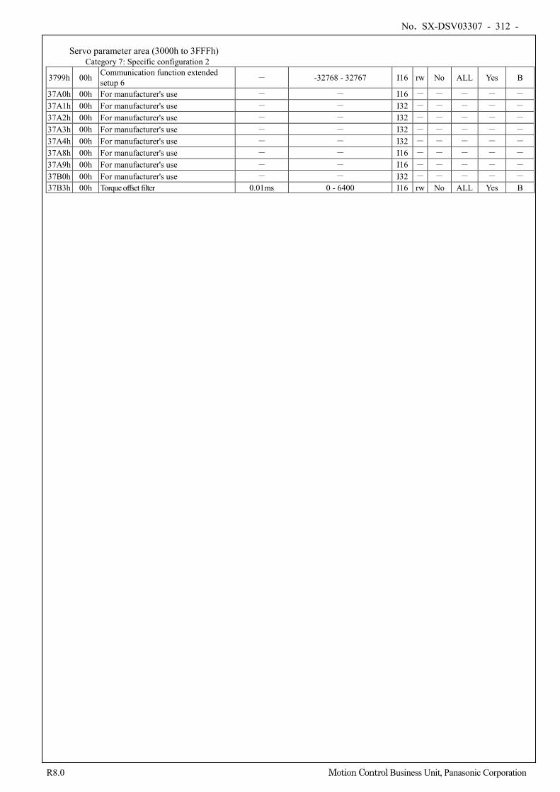
No. SX-DSV03307 - 312 -
R8.0 Motion Control Business Unit, Panasonic Corporation
Servo parameter area (3000h to 3FFFh)
Category 7: Specific configuration 2
3799h 00h Communication function extended setup 6 - -32768 - 32767 I16 rw No ALL Yes B
37A0h 00h For manufacturer's use - - I16 - - - - - 37A1h 00h For manufacturer's use - - I32 - - - - - 37A2h 00h For manufacturer's use - - I32 - - - - - 37A3h 00h For manufacturer's use - - I32 - - - - - 37A4h 00h For manufacturer's use - - I32 - - - - - 37A8h 00h For manufacturer's use - - I16 - - - - - 37A9h 00h For manufacturer's use - - I16 - - - - - 37B0h 00h For manufacturer's use - - I32 - - - - - 37B3h 00h Torque offset filter 0.01ms 0 - 6400 I16 rw No ALL Yes B
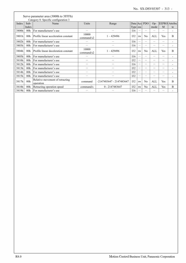
No. SX-DSV03307 - 313 -
R8.0 Motion Control Business Unit, Panasonic Corporation
Servo parameter area (3000h to 3FFFh) Category 8: Specific configuration 3
Index Sub- Index
Name Units Range Data Type
Access
PDO Op- mode
EEPROM
Attribute
3800h 00h For manufacturer’s use - - I16 - - - - -
3801h 00h Profile linear acceleration constant 10000 command/s2 1 – 429496 I32 rw No ALL Yes B
3802h 00h For manufacturer’s use - - I16 - - - - - 3803h 00h For manufacturer’s use - - I16 - - - - -
3804h 00h Profile linear deceleration constant 10000 command/s2 1 – 429496 I32 rw No ALL Yes B
3805h 00h For manufacturer’s use - - I16 - - - - - 3810h 00h For manufacturer’s use - - I32 - - - - - 3812h 00h For manufacturer’s use - - I16 - - - - - 3813h 00h For manufacturer’s use - - I32 - - - - - 3814h 00h For manufacturer’s use - - I32 - - - - - 3815h 00h For manufacturer’s use - - I32 - - - - -
3817h 00h Relative movement of retracting operation command -2147483647 - 2147483647 I32 rw No ALL Yes B
3818h 00h Retracting operation speed command/s 0 - 2147483647 I32 rw No ALL Yes B 3819h 00h For manufacturer’s use - - I16 - - - - -
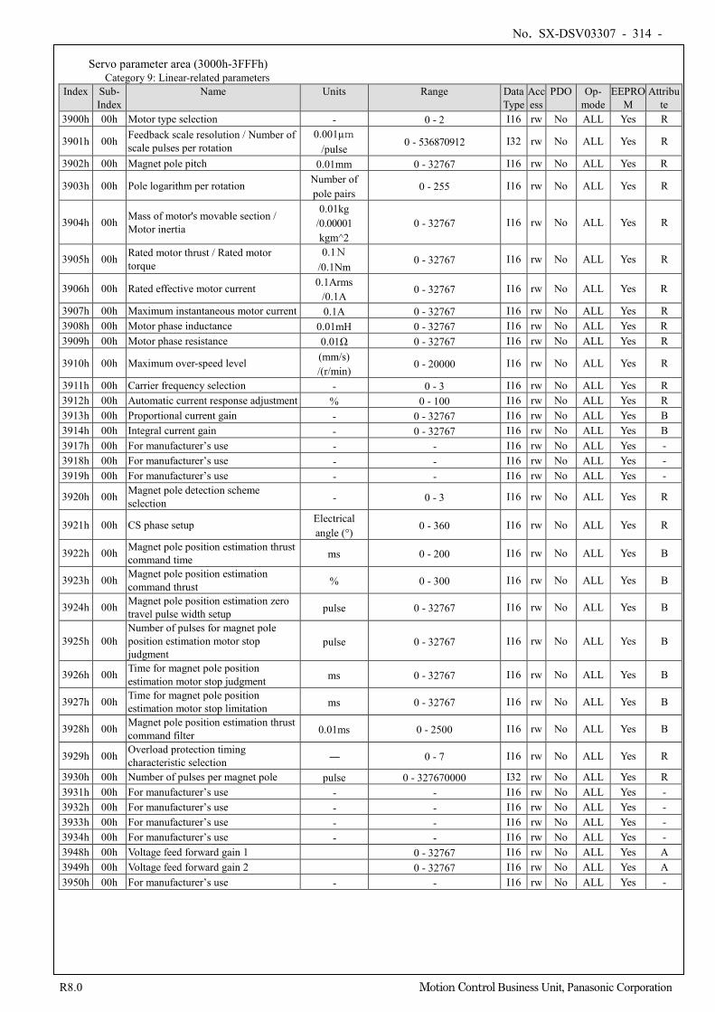
No. SX-DSV03307 - 314 -
R8.0 Motion Control Business Unit, Panasonic Corporation
Servo parameter area (3000h-3FFFh)
Category 9: Linear-related parameters Index Sub-
Index Name Units Range Data
Type Access
PDO Op- mode
EEPROM
Attribute
3900h 00h Motor type selection - 0 - 2 I16 rw No ALL Yes R
3901h 00h Feedback scale resolution / Number of scale pulses per rotation
0.001μm /pulse
0 - 536870912 I32 rw No ALL Yes R
3902h 00h Magnet pole pitch 0.01mm 0 - 32767 I16 rw No ALL Yes R
3903h 00h Pole logarithm per rotation Number of pole pairs
0 - 255 I16 rw No ALL Yes R
3904h 00h Mass of motor's movable section / Motor inertia
0.01kg /0.00001 kgm^2
0 - 32767 I16 rw No ALL Yes R
3905h 00h Rated motor thrust / Rated motor torque
0.1N /0.1Nm
0 - 32767 I16 rw No ALL Yes R
3906h 00h Rated effective motor current 0.1Arms /0.1A
0 - 32767 I16 rw No ALL Yes R
3907h 00h Maximum instantaneous motor current 0.1A 0 - 32767 I16 rw No ALL Yes R 3908h 00h Motor phase inductance 0.01mH 0 - 32767 I16 rw No ALL Yes R 3909h 00h Motor phase resistance 0.01Ω 0 - 32767 I16 rw No ALL Yes R
3910h 00h Maximum over-speed level (mm/s) /(r/min)
0 - 20000 I16 rw No ALL Yes R
3911h 00h Carrier frequency selection - 0 - 3 I16 rw No ALL Yes R 3912h 00h Automatic current response adjustment % 0 - 100 I16 rw No ALL Yes R 3913h 00h Proportional current gain - 0 - 32767 I16 rw No ALL Yes B 3914h 00h Integral current gain - 0 - 32767 I16 rw No ALL Yes B 3917h 00h For manufacturer’s use - - I16 rw No ALL Yes - 3918h 00h For manufacturer’s use - - I16 rw No ALL Yes - 3919h 00h For manufacturer’s use - - I16 rw No ALL Yes -
3920h 00h Magnet pole detection scheme selection - 0 - 3 I16 rw No ALL Yes R
3921h 00h CS phase setup Electrical angle (°)
0 - 360 I16 rw No ALL Yes R
3922h 00h Magnet pole position estimation thrust command time ms 0 - 200 I16 rw No ALL Yes B
3923h 00h Magnet pole position estimation command thrust % 0 - 300 I16 rw No ALL Yes B
3924h 00h Magnet pole position estimation zero travel pulse width setup pulse 0 - 32767 I16 rw No ALL Yes B
3925h 00h Number of pulses for magnet pole position estimation motor stop judgment
pulse 0 - 32767 I16 rw No ALL Yes B
3926h 00h Time for magnet pole position estimation motor stop judgment ms 0 - 32767 I16 rw No ALL Yes B
3927h 00h Time for magnet pole position estimation motor stop limitation ms 0 - 32767 I16 rw No ALL Yes B
3928h 00h Magnet pole position estimation thrust command filter 0.01ms 0 - 2500 I16 rw No ALL Yes B
3929h 00h Overload protection timing characteristic selection ― 0 - 7 I16 rw No ALL Yes R
3930h 00h Number of pulses per magnet pole pulse 0 - 327670000 I32 rw No ALL Yes R 3931h 00h For manufacturer’s use - - I16 rw No ALL Yes - 3932h 00h For manufacturer’s use - - I16 rw No ALL Yes - 3933h 00h For manufacturer’s use - - I16 rw No ALL Yes - 3934h 00h For manufacturer’s use - - I16 rw No ALL Yes - 3948h 00h Voltage feed forward gain 1 0 - 32767 I16 rw No ALL Yes A 3949h 00h Voltage feed forward gain 2 0 - 32767 I16 rw No ALL Yes A 3950h 00h For manufacturer’s use - - I16 rw No ALL Yes -
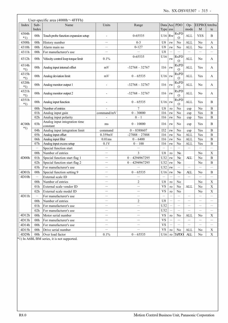
No. SX-DSV03307 - 315 -
R8.0 Motion Control Business Unit, Panasonic Corporation
User-specific area (4000h~4FFFh) Index Sub-
Index Name Units Range Data
Type Access
PDO Op- mode
EEPROM
Attribute
4304h *1) 00h Touch probe function expansion setup - 0-65535 U16 Rw RxPD
O ALL YES B
4308h 00h History number - 0-3 U8 rw No ALL No A 4310h 00h Alarm main no - 0-127 U8 rw No ALL No A 4311h 00h For manufacturer's use - - U8 - - - - -
4312h 00h Velocity control loop torque limit 0.1% 0-65535 U16 rw RxPDO ALL No A
4314h *1) 00h Analog input internal offset mV -32768 – 32767 I16 rw RxPD
O ALL Yes A
4315h *1) 00h Analog deviation limit mV 0 – 65535 U16 rw RxPD
O ALL Yes A
4320h *1) 00h Analog monitor output 1 - -32768 – 32767 I16 rw RxPD
O ALL No A
4321h *1) 00h Analog monitor output 2 - -32768 – 32767 I16 rw RxPD
O ALL No A
4351h *1) 00h Analog input function - 0 – 65535 U16 rw RxPD
O ALL Yes B
4C00h *1)
00h Number of entries - 7 U8 ro No csp No B 01h Analog input gain command/mV 0 – 30000 I16 rw No csp Yes B 02h Analog input polarity - 0 – 1 I16 rw No csp Yes B
03h Analog input integration time constant ms 0 – 10000 I16 rw No csp Yes B
04h Analog input integration limit command 0 – 8388607 I32 rw No csp Yes B 05h Analog input offset 0.359mV -27888 – 27888 I16 rw No ALL Yes B 06h Analog input filter 0.01ms 0 – 6400 I16 rw No ALL Yes B 07h Analog input excess setup 0.1V 0 – 100 I16 rw No ALL Yes B
4D00h
- Special function start - - - - - - - - 00h Number of entries - 3 U8 ro No
ALL No X
01h Special function start flag 1 - 0 – 4294967295 U32 rw No No B 02h Special function start flag 2 - 0 – 4294967295 U32 rw No No B 03h For manufacturer's use - - U32 rw - - - -
4D01h 00h Special function setting 9 - 0 – 65535 U16 rw No ALL No B 4D10h - External scale ID - - - - - - - -
00h Number of entries - 2 U8 ro No ALL
No X 01h External scale vendor ID - - VS ro No No X 02h External scale model ID - - VS ro No No X
4D11h - For manufacturer's use - - - - - - - - 00h Number of entries - 2 U8 - - - - - 01h For manufacturer's use - - U32 - - - - - 02h For manufacturer's use - - U32 - - - - -
4D12h 00h Motor serial number - - VS ro No ALL No X 4D13h 00h For manufacturer's use - - VS - - - - - 4D14h 00h For manufacturer's use - - VS - - - - - 4D15h 00h Drive serial number - - VS ro No ALL No X 4D29h 00h Over load factor 0.1% 0 – 65535 U16 ro TxPDO ALL No X
*1) In A6BL/BM series, it is not supported.
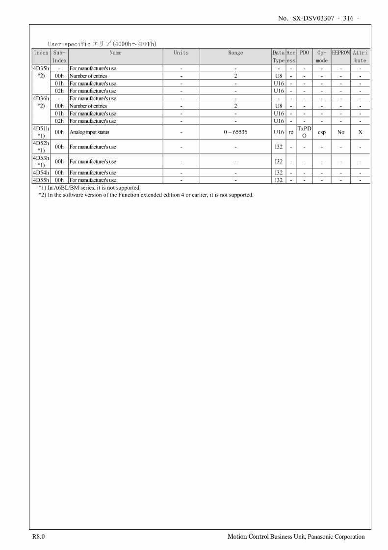
No. SX-DSV03307 - 316 -
R8.0 Motion Control Business Unit, Panasonic Corporation
User-specificエリア(4000h~4FFFh)
Index Sub-
Index
Name Units Range Data
Type
Acc
ess
PDO Op-
mode
EEPROM Attri
bute
4D35h *2)
- For manufacturer's use - - - - - - - - 00h Number of entries - 2 U8 - - - - - 01h For manufacturer's use - - U16 - - - - - 02h For manufacturer's use - - U16 - - - - -
4D36h *2)
- For manufacturer's use - - - - - - - - 00h Number of entries - 2 U8 - - - - - 01h For manufacturer's use - - U16 - - - - - 02h For manufacturer's use - - U16 - - - - -
4D51h *1) 00h Analog input status - 0 – 65535 U16 ro TxPD
O csp No X
4D52h *1) 00h For manufacturer's use - - I32 - - - - -
4D53h *1) 00h For manufacturer's use - - I32 - - - - -
4D54h 00h For manufacturer's use - - I32 - - - - - 4D55h 00h For manufacturer's use - - I32 - - - - -
*1) In A6BL/BM series, it is not supported. *2) In the software version of the Function extended edition 4 or earlier, it is not supported.
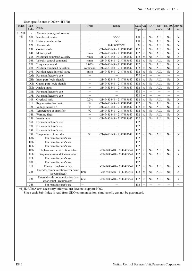
No. SX-DSV03307 - 317 -
R8.0 Motion Control Business Unit, Panasonic Corporation
User-specific area (4000h~4FFFh) Index Sub-
Index Name Units Range Data Type
Access
PDO Op- mode
EEPROM
Attribute
4DA0h *1)
- Alarm accessory information - - - - - - - - 00h Number of entries - 36-36 U8 ro No ALL No X 01h History number echo - 0-3 U8 ro No ALL No X 02h Alarm code - 0-4294967295 U32 ro No ALL No X 03h Control mode - -2147483648 – 2147483647 I32 ro No ALL No X 04h Motor speed r/min -2147483648 – 2147483647 I32 ro No ALL No X 05h Positional command velocity r/min -2147483648 – 2147483647 I32 ro No ALL No X 06h Velocity control command r/min -2147483648 – 2147483647 I32 ro No ALL No X 07h Torque command 0.05% -2147483648 – 2147483647 I32 ro No ALL No X 08h Position command deviation command -2147483648 – 2147483647 I32 ro No ALL No X 09h Position actual internal value pulse -2147483648 – 2147483647 I32 ro No ALL No X 0Ah For manufacturer's use - - I32 - - - - - 0Bh Input port (logic signal) - -2147483648 – 2147483647 I32 ro No ALL No X 0Ch Output port (logic signal) - -2147483648 – 2147483647 I32 ro No ALL No X 0Dh Analog input - -2147483648 – 2147483647 I32 ro No ALL No X 0Eh For manufacturer's use - - I32 - - - - - 0Fh For manufacturer's use - - I32 - - - - - 10h Overload ratio 0.2% -2147483648 – 2147483647 I32 ro No ALL No X 11h Regenerative load ratio % -2147483648 – 2147483647 I32 ro No ALL No X 12h Voltage across PN V -2147483648 – 2147483647 I32 ro No ALL No X 13h Temperature of amplifier °C -2147483648 – 2147483647 I32 ro No ALL No X 14h Warning flags - -2147483648 – 2147483647 I32 ro No ALL No X 15h Inertia ratio % -2147483648 – 2147483647 I32 ro No ALL No X 16h For manufacturer's use - - I32 - - - - - 17h For manufacturer's use - - I32 - - - - - 18h For manufacturer's use - - I32 - - - - - 19h Temperature of encoder °C -2147483648 – 2147483647 I32 ro No ALL No X 1Ah For manufacturer's use - - I32 - - - - - 1Bh For manufacturer's use - - I32 - - - - - 1Ch For manufacturer's use - - I32 - - - - - 1Dh U-phase current detection value - -2147483648 – 2147483647 I32 ro No ALL No X 1Eh W-phase current detection value - -2147483648 – 2147483647 I32 ro No ALL No X 1Fh For manufacturer's use - - I32 - - - - - 20h For manufacturer's use - - I32 - - - - - 21h Encoder single-turn data - -2147483648 – 2147483647 I32 ro No ALL No X
22h Encoder communication error count (accumulated) time -2147483648 – 2147483647 I32 ro No ALL No X
23h External scale communication data error count (accumulated) time -2147483648 – 2147483647 I32 ro No ALL No X
24h For manufacturer's use - - I32 - - - - - *1)4DA0h(Alarm accessory information) does not support PDO.
Since each Sub-Index is read from SDO communication, simultaneity can not be guaranteed.
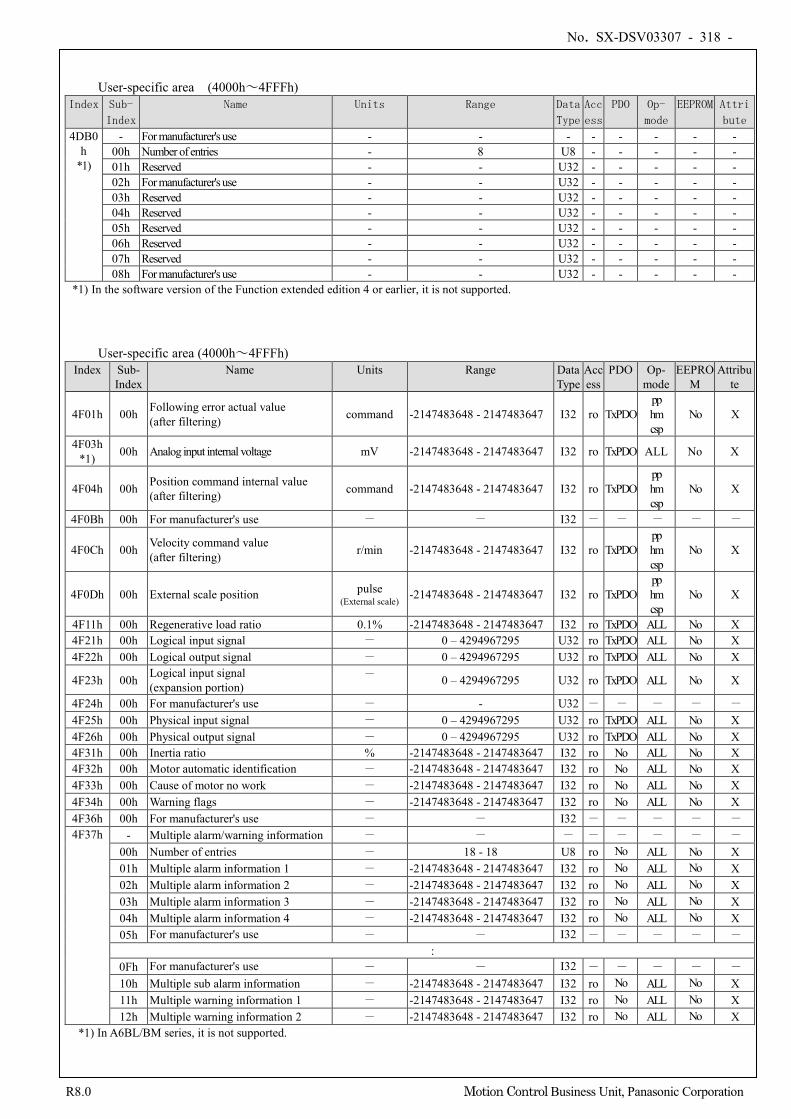
No. SX-DSV03307 - 318 -
R8.0 Motion Control Business Unit, Panasonic Corporation
User-specific area (4000h~4FFFh)
Index Sub-
Index
Name Units Range Data
Type
Acc
ess
PDO Op-
mode
EEPROM Attri
bute
4DB0h
*1)
- For manufacturer's use - - - - - - - - 00h Number of entries - 8 U8 - - - - - 01h Reserved - - U32 - - - - - 02h For manufacturer's use - - U32 - - - - - 03h Reserved - - U32 - - - - - 04h Reserved - - U32 - - - - - 05h Reserved - - U32 - - - - - 06h Reserved - - U32 - - - - - 07h Reserved - - U32 - - - - - 08h For manufacturer's use - - U32 - - - - -
*1) In the software version of the Function extended edition 4 or earlier, it is not supported.
User-specific area (4000h~4FFFh) Index Sub-
Index Name Units Range Data
Type Access
PDO Op- mode
EEPROM
Attribute
4F01h 00h Following error actual value (after filtering) command -2147483648 - 2147483647 I32 ro TxPDO
pp hm csp
No X
4F03h *1) 00h Analog input internal voltage mV -2147483648 - 2147483647 I32 ro TxPDO ALL No X
4F04h 00h Position command internal value (after filtering) command -2147483648 - 2147483647 I32 ro TxPDO
pp hm csp
No X
4F0Bh 00h For manufacturer's use - - I32 - - - - -
4F0Ch 00h Velocity command value (after filtering) r/min -2147483648 - 2147483647 I32 ro TxPDO
pp hm csp
No X
4F0Dh 00h External scale position pulse (External scale) -2147483648 - 2147483647 I32 ro TxPDO
pp hm csp
No X
4F11h 00h Regenerative load ratio 0.1% -2147483648 - 2147483647 I32 ro TxPDO ALL No X 4F21h 00h Logical input signal - 0 – 4294967295 U32 ro TxPDO ALL No X 4F22h 00h Logical output signal - 0 – 4294967295 U32 ro TxPDO ALL No X
4F23h 00h Logical input signal (expansion portion)
- 0 – 4294967295 U32 ro TxPDO ALL No X
4F24h 00h For manufacturer's use - - U32 - - - - - 4F25h 00h Physical input signal - 0 – 4294967295 U32 ro TxPDO ALL No X 4F26h 00h Physical output signal - 0 – 4294967295 U32 ro TxPDO ALL No X 4F31h 00h Inertia ratio % -2147483648 - 2147483647 I32 ro No ALL No X 4F32h 00h Motor automatic identification - -2147483648 - 2147483647 I32 ro No ALL No X 4F33h 00h Cause of motor no work - -2147483648 - 2147483647 I32 ro No ALL No X 4F34h 00h Warning flags - -2147483648 - 2147483647 I32 ro No ALL No X 4F36h 00h For manufacturer's use - - I32 - - - - - 4F37h - Multiple alarm/warning information - - - - - - - -
00h Number of entries - 18 - 18 U8 ro No ALL No X 01h Multiple alarm information 1 - -2147483648 - 2147483647 I32 ro No ALL No X 02h Multiple alarm information 2 - -2147483648 - 2147483647 I32 ro No ALL No X 03h Multiple alarm information 3 - -2147483648 - 2147483647 I32 ro No ALL No X 04h Multiple alarm information 4 - -2147483648 - 2147483647 I32 ro No ALL No X 05h For manufacturer's use - - I32 - - - - -
: 0Fh For manufacturer's use - - I32 - - - - - 10h Multiple sub alarm information - -2147483648 - 2147483647 I32 ro No ALL No X 11h Multiple warning information 1 - -2147483648 - 2147483647 I32 ro No ALL No X 12h Multiple warning information 2 - -2147483648 - 2147483647 I32 ro No ALL No X
*1) In A6BL/BM series, it is not supported.
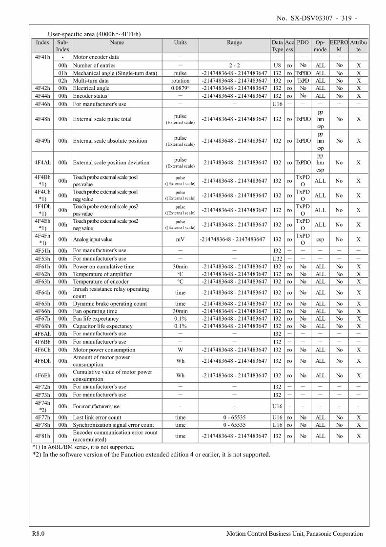
No. SX-DSV03307 - 319 -
R8.0 Motion Control Business Unit, Panasonic Corporation
User-specific area (4000h~4FFFh) Index Sub-
Index Name Units Range Data
Type Access
PDO Op- mode
EEPROM
Attribute
4F41h - Motor encoder data - - - - - - - - 00h Number of entries - 2 - 2 U8 ro No ALL No X 01h Mechanical angle (Single-turn data) pulse -2147483648 - 2147483647 I32 ro TxPDO ALL No X 02h Multi-turn data rotation -2147483648 - 2147483647 I32 ro TxPD ALL No X
4F42h 00h Electrical angle 0.0879° -2147483648 - 2147483647 I32 ro No ALL No X 4F44h 00h Encoder status - -2147483648 - 2147483647 I32 ro No ALL No X 4F46h 00h For manufacturer's use - - U16 - - - - -
4F48h 00h External scale pulse total pulse (External scale)
-2147483648 - 2147483647 I32 ro TxPDO pp hm csp
No X
4F49h 00h External scale absolute position pulse (External scale)
-2147483648 - 2147483647 I32 ro TxPDO pp hm csp
No X
4F4Ah 00h External scale position deviation pulse (External scale) -2147483648 - 2147483647 I32 ro TxPDO
pp hm csp
No X
4F4Bh *1) 00h Touch probe external scale pos1
pos value pulse
((External scale) -2147483648 - 2147483647 I32 ro TxPDO ALL No X
4F4Ch *1) 00h Touch probe external scale pos1
neg value pulse
((External scale) -2147483648 - 2147483647 I32 ro TxPDO ALL No X
4F4Dh *1) 00h Touch probe external scale pos2
pos value pulse
((External scale) -2147483648 - 2147483647 I32 ro TxPDO ALL No X
4F4Eh *1) 00h Touch probe external scale pos2
neg value pulse
((External scale) -2147483648 - 2147483647 I32 ro TxPDO ALL No X
4F4Fh *1) 00h Analog input value mV -2147483648 - 2147483647 I32 ro TxPD
O csp No X
4F51h 00h For manufacturer's use - - I32 - - - - - 4F53h 00h For manufacturer's use - - U32 - - - - - 4F61h 00h Power on cumulative time 30min -2147483648 - 2147483647 I32 ro No ALL No X 4F62h 00h Temperature of amplifier °C -2147483648 - 2147483647 I32 ro No ALL No X 4F63h 00h Temperature of encoder °C -2147483648 - 2147483647 I32 ro No ALL No X
4F64h 00h Inrush resistance relay operating count time -2147483648 - 2147483647 I32 ro No ALL No X
4F65h 00h Dynamic brake operating count time -2147483648 - 2147483647 I32 ro No ALL No X 4F66h 00h Fan operating time 30min -2147483648 - 2147483647 I32 ro No ALL No X 4F67h 00h Fan life expectancy 0.1% -2147483648 - 2147483647 I32 ro No ALL No X 4F68h 00h Capacitor life expectancy 0.1% -2147483648 - 2147483647 I32 ro No ALL No X 4F6Ah 00h For manufacturer's use - - I32 - - - - - 4F6Bh 00h For manufacturer's use - - I32 - - - - - 4F6Ch 00h Motor power consumption W -2147483648 - 2147483647 I32 ro No ALL No X
4F6Dh 00h Amount of motor power consumption Wh -2147483648 - 2147483647 I32 ro No ALL No X
4F6Eh 00h Cumulative value of motor power consumption Wh -2147483648 - 2147483647 I32 ro No ALL No X
4F72h 00h For manufacturer's use - - I32 - - - - - 4F73h 00h For manufacturer's use - - I32 - - - - - 4F74h
*2) 00h For manufacturer's use - - U16 - - - - -
4F77h 00h Lost link error count time 0 - 65535 U16 ro No ALL No X 4F78h 00h Synchronization signal error count time 0 - 65535 U16 ro No ALL No X
4F81h 00h Encoder communication error count (accumulated) time -2147483648 - 2147483647 I32 ro No ALL No X
*1) In A6BL/BM series, it is not supported. *2) In the software version of the Function extended edition 4 or earlier, it is not supported.
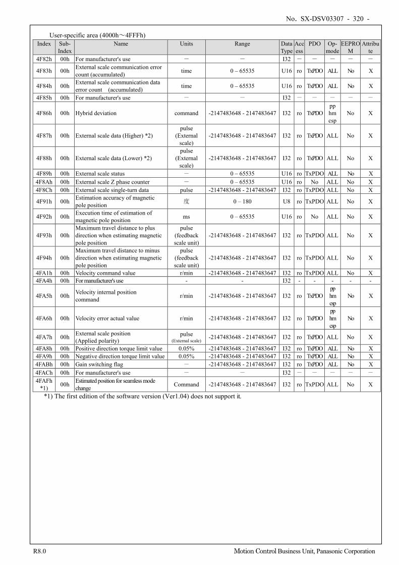
No. SX-DSV03307 - 320 -
R8.0 Motion Control Business Unit, Panasonic Corporation
User-specific area (4000h~4FFFh) Index Sub-
Index Name Units Range Data
Type Access
PDO Op- mode
EEPROM
Attribute
4F82h 00h For manufacturer's use - - I32 - - - - -
4F83h 00h External scale communication error count (accumulated) time 0 – 65535 U16 ro TxPDO ALL No X
4F84h 00h External scale communication data error count (accumulated) time 0 – 65535 U16 ro TxPDO ALL No X
4F85h 00h For manufacturer's use - - I32 - - - - -
4F86h 00h Hybrid deviation command -2147483648 - 2147483647 I32 ro TxPDO pp hm csp
No X
4F87h 00h External scale data (Higher) *2) pulse
(External scale)
-2147483648 - 2147483647 I32 ro TxPDO ALL No X
4F88h 00h External scale data (Lower) *2) pulse
(External scale)
-2147483648 - 2147483647 I32 ro TxPDO ALL No X
4F89h 00h External scale status - 0 – 65535 U16 ro TxPDO ALL No X 4F8Ah 00h External scale Z phase counter - 0 – 65535 U16 ro No ALL No X 4F8Ch 00h External scale single-turn data pulse -2147483648 - 2147483647 I32 ro TxPDO ALL No X
4F91h 00h Estimation accuracy of magnetic pole position 度 0 – 180 U8 ro TxPDO ALL No X
4F92h 00h Execution time of estimation of magnetic pole position ms 0 – 65535 U16 ro No ALL No X
4F93h 00h Maximum travel distance to plus direction when estimating magnetic pole position
pulse (feedback scale unit)
-2147483648 - 2147483647 I32 ro TxPDO ALL No X
4F94h 00h Maximum travel distance to minus direction when estimating magnetic pole position
pulse (feedback scale unit)
-2147483648 - 2147483647 I32 ro TxPDO ALL No X
4FA1h 00h Velocity command value r/min -2147483648 - 2147483647 I32 ro TxPDO ALL No X 4FA4h 00h For manufacturer's use - - I32 - - - - -
4FA5h 00h Velocity internal position command r/min -2147483648 - 2147483647 I32 ro TxPDO
pp hm csp
No X
4FA6h 00h Velocity error actual value r/min -2147483648 - 2147483647 I32 ro TxPDO pp hm csp
No X
4FA7h 00h External scale position (Applied polarity)
pulse (External scale) -2147483648 - 2147483647 I32 ro TxPDO ALL No X
4FA8h 00h Positive direction torque limit value 0.05% -2147483648 - 2147483647 I32 ro TxPDO ALL No X 4FA9h 00h Negative direction torque limit value 0.05% -2147483648 - 2147483647 I32 ro TxPDO ALL No X 4FABh 00h Gain switching flag - -2147483648 - 2147483647 I32 ro TxPDO ALL No X 4FACh 00h For manufacturer's use - - I32 - - - - - 4FAFh
*1) 00h Estimated position for seamless mode change Command -2147483648 - 2147483647 I32 ro TxPDO ALL No X
*1) The first edition of the software version (Ver1.04) does not support it.
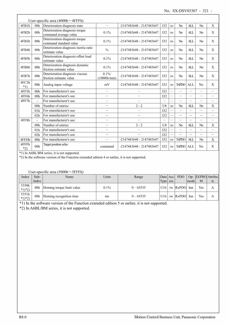
No. SX-DSV03307 - 321 -
R8.0 Motion Control Business Unit, Panasonic Corporation
User-specific area (4000h~4FFFh)
4FB1h 00h Deterioration diagnosis state - -2147483648 - 2147483647 I32 ro No ALL No X
4FB2h 00h Deterioration diagnosis torque command average value 0.1% -2147483648 - 2147483647 I32 ro No ALL No X
4FB3h 00h Deterioration diagnosis torque command standard value 0.1% -2147483648 - 2147483647 I32 ro No ALL No X
4FB4h 00h Deterioration diagnosis inertia ratio estimate value % -2147483648 - 2147483647 I32 ro No ALL No X
4FB5h 00h Deterioration diagnosis offset load estimate value 0.1% -2147483648 - 2147483647 I32 ro No ALL No X
4FB6h 00h Deterioration diagnosis dynamic friction estimate value 0.1% -2147483648 - 2147483647 I32 ro No ALL No X
4FB7h 00h Deterioration diagnosis viscous friction estimate value
0.1%/ (10000r/min) -2147483648 - 2147483647 I32 ro No ALL No X
4FC2h *1) 00h Analog input voltage mV -2147483648 - 2147483647 I32 ro TxPDO ALL No X
4FF5h 00h For manufacturer's use - - I32 - - - - - 4FF6h 00h For manufacturer's use - - I32 - - - - - 4FF7h - For manufacturer's use - - - - - - - -
00h Number of entries - 2 - 2 U8 ro No ALL No X 01h For manufacturer's use - - I32 - - - - - 02h For manufacturer's use - - I32 - - - - -
4FF8h - For manufacturer's use - - - - - - - - 00h Number of entries - 2 - 2 U8 ro No ALL No X 01h For manufacturer's use - - I32 - - - - - 02h For manufacturer's use - - I32 - - - - -
4FFDh 00h For manufacturer's use - -2147483648 - 2147483647 I32 ro TxPDO ALL No X 4FFFh
*2) 00h Target position echo command -2147483648 - 2147483647 I32 ro TxPDO ALL No X
*1) In A6BL/BM series, it is not supported. *2) In the software version of the Function extended edition 4 or earlier, it is not supported.
User-specific area (5000h~5FFFh) Index Sub-
Index Name Units Range Data
Type Access
PDO Op- mode
EEPROM
Attribute
5350h *1)*2) 00h Homing torque limit value 0.1% 0 – 65535 U16 rw RxPDO hm Yes A
5351h *1)*2) 00h Homing recognition time ms 0 – 65535 U16 rw RxPDO hm Yes A
*1) In the software version of the Function extended edition 5 or earlier, it is not supported. *2) In A6BL/BM series, it is not supported.
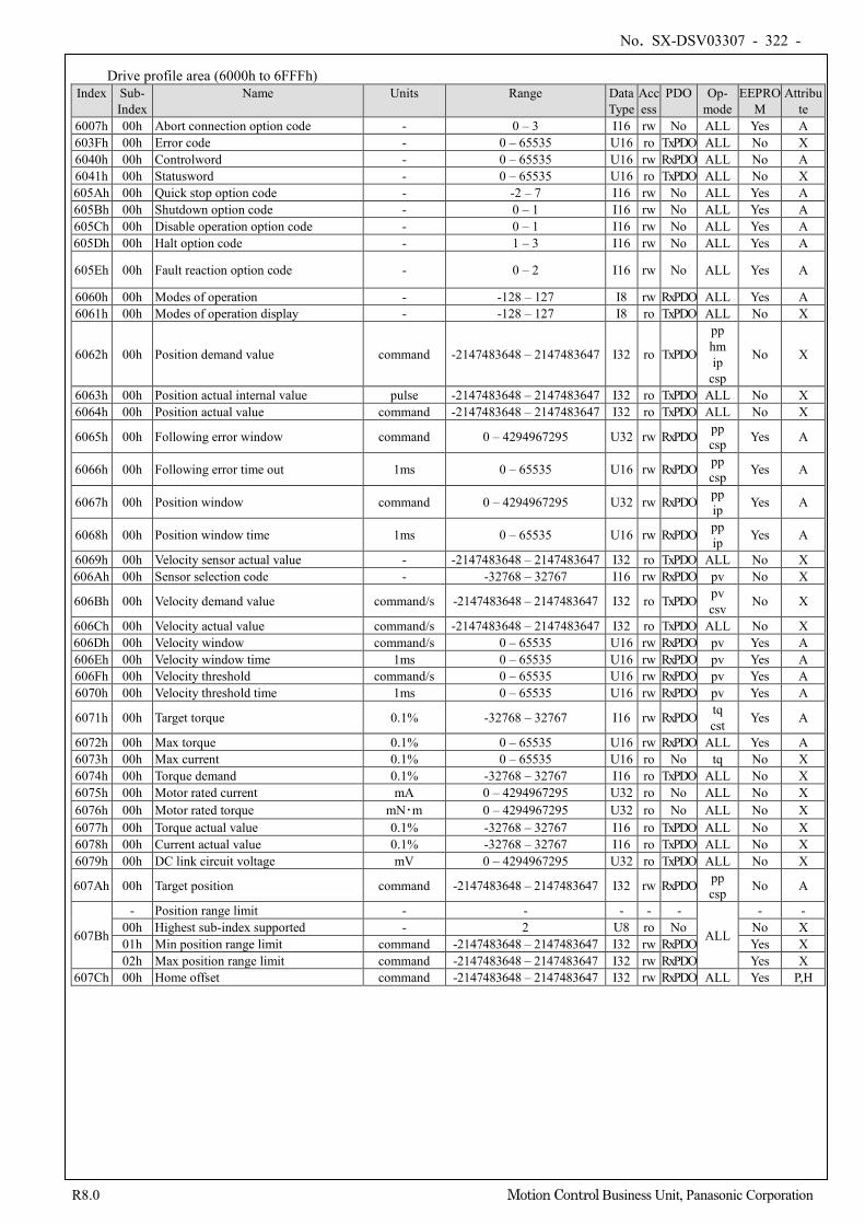
No. SX-DSV03307 - 322 -
R8.0 Motion Control Business Unit, Panasonic Corporation
Drive profile area (6000h to 6FFFh) Index Sub-
Index Name Units Range Data
Type Access
PDO Op- mode
EEPROM
Attribute
6007h 00h Abort connection option code - 0 – 3 I16 rw No ALL Yes A 603Fh 00h Error code - 0 – 65535 U16 ro TxPDO ALL No X 6040h 00h Controlword - 0 – 65535 U16 rw RxPDO ALL No A 6041h 00h Statusword - 0 – 65535 U16 ro TxPDO ALL No X 605Ah 00h Quick stop option code - -2 – 7 I16 rw No ALL Yes A 605Bh 00h Shutdown option code - 0 – 1 I16 rw No ALL Yes A 605Ch 00h Disable operation option code - 0 – 1 I16 rw No ALL Yes A 605Dh 00h Halt option code - 1 – 3 I16 rw No ALL Yes A
605Eh 00h Fault reaction option code - 0 – 2 I16 rw No ALL Yes A
6060h 00h Modes of operation - -128 – 127 I8 rw RxPDO ALL Yes A 6061h 00h Modes of operation display - -128 – 127 I8 ro TxPDO ALL No X
6062h 00h Position demand value command -2147483648 – 2147483647 I32 ro TxPDO
pp hm ip
csp
No X
6063h 00h Position actual internal value pulse -2147483648 – 2147483647 I32 ro TxPDO ALL No X 6064h 00h Position actual value command -2147483648 – 2147483647 I32 ro TxPDO ALL No X
6065h 00h Following error window command 0 – 4294967295 U32 rw RxPDO pp csp Yes A
6066h 00h Following error time out 1ms 0 – 65535 U16 rw RxPDO pp csp Yes A
6067h 00h Position window command 0 – 4294967295 U32 rw RxPDO pp ip Yes A
6068h 00h Position window time 1ms 0 – 65535 U16 rw RxPDO pp ip Yes A
6069h 00h Velocity sensor actual value - -2147483648 – 2147483647 I32 ro TxPDO ALL No X 606Ah 00h Sensor selection code - -32768 – 32767 I16 rw RxPDO pv No X
606Bh 00h Velocity demand value command/s -2147483648 – 2147483647 I32 ro TxPDO pv csv No X
606Ch 00h Velocity actual value command/s -2147483648 – 2147483647 I32 ro TxPDO ALL No X 606Dh 00h Velocity window command/s 0 – 65535 U16 rw RxPDO pv Yes A 606Eh 00h Velocity window time 1ms 0 – 65535 U16 rw RxPDO pv Yes A 606Fh 00h Velocity threshold command/s 0 – 65535 U16 rw RxPDO pv Yes A 6070h 00h Velocity threshold time 1ms 0 – 65535 U16 rw RxPDO pv Yes A
6071h 00h Target torque 0.1% -32768 – 32767 I16 rw RxPDO tq cst Yes A
6072h 00h Max torque 0.1% 0 – 65535 U16 rw RxPDO ALL Yes A 6073h 00h Max current 0.1% 0 – 65535 U16 ro No tq No X 6074h 00h Torque demand 0.1% -32768 – 32767 I16 ro TxPDO ALL No X 6075h 00h Motor rated current mA 0 – 4294967295 U32 ro No ALL No X 6076h 00h Motor rated torque mN・m 0 – 4294967295 U32 ro No ALL No X 6077h 00h Torque actual value 0.1% -32768 – 32767 I16 ro TxPDO ALL No X 6078h 00h Current actual value 0.1% -32768 – 32767 I16 ro TxPDO ALL No X 6079h 00h DC link circuit voltage mV 0 – 4294967295 U32 ro TxPDO ALL No X
607Ah 00h Target position command -2147483648 – 2147483647 I32 rw RxPDO pp csp No A
607Bh
- Position range limit - - - - -
ALL
- - 00h Highest sub-index supported - 2 U8 ro No No X 01h Min position range limit command -2147483648 – 2147483647 I32 rw RxPDO Yes X 02h Max position range limit command -2147483648 – 2147483647 I32 rw RxPDO Yes X
607Ch 00h Home offset command -2147483648 – 2147483647 I32 rw RxPDO ALL Yes P,H
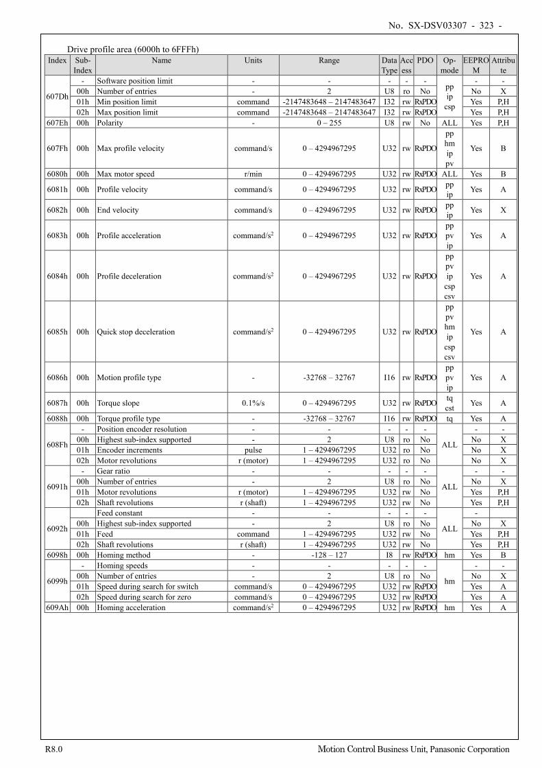
No. SX-DSV03307 - 323 -
R8.0 Motion Control Business Unit, Panasonic Corporation
Drive profile area (6000h to 6FFFh)
Index Sub- Index
Name Units Range Data Type
Access
PDO Op- mode
EEPROM
Attribute
607Dh
- Software position limit - - - - - pp ip
csp
- - 00h Number of entries - 2 U8 ro No No X 01h Min position limit command -2147483648 – 2147483647 I32 rw RxPDO Yes P,H 02h Max position limit command -2147483648 – 2147483647 I32 rw RxPDO Yes P,H
607Eh 00h Polarity - 0 – 255 U8 rw No ALL Yes P,H
607Fh 00h Max profile velocity command/s 0 – 4294967295 U32 rw RxPDO
pp hm ip pv
Yes B
6080h 00h Max motor speed r/min 0 – 4294967295 U32 rw RxPDO ALL Yes B
6081h 00h Profile velocity command/s 0 – 4294967295 U32 rw RxPDO pp ip Yes A
6082h 00h End velocity command/s 0 – 4294967295 U32 rw RxPDO pp ip Yes X
6083h 00h Profile acceleration command/s2 0 – 4294967295 U32 rw RxPDO pp pv ip
Yes A
6084h 00h Profile deceleration command/s2 0 – 4294967295 U32 rw RxPDO
pp pv ip
csp csv
Yes A
6085h 00h Quick stop deceleration command/s2 0 – 4294967295 U32 rw RxPDO
pp pv hm ip
csp csv
Yes A
6086h 00h Motion profile type - -32768 – 32767 I16 rw RxPDO pp pv ip
Yes A
6087h 00h Torque slope 0.1%/s 0 – 4294967295 U32 rw RxPDO tq cst Yes A
6088h 00h Torque profile type - -32768 – 32767 I16 rw RxPDO tq Yes A
608Fh
- Position encoder resolution - - - - -
ALL
- - 00h Highest sub-index supported - 2 U8 ro No No X 01h Encoder increments pulse 1 – 4294967295 U32 ro No No X 02h Motor revolutions r (motor) 1 – 4294967295 U32 ro No No X
6091h
- Gear ratio - - - - -
ALL
- - 00h Number of entries - 2 U8 ro No No X 01h Motor revolutions r (motor) 1 – 4294967295 U32 rw No Yes P,H 02h Shaft revolutions r (shaft) 1 – 4294967295 U32 rw No Yes P,H
6092h
Feed constant - - - - -
ALL
- 00h Highest sub-index supported - 2 U8 ro No No X 01h Feed command 1 – 4294967295 U32 rw No Yes P,H 02h Shaft revolutions r (shaft) 1 – 4294967295 U32 rw No Yes P,H
6098h 00h Homing method - -128 – 127 I8 rw RxPDO hm Yes B
6099h
- Homing speeds - - - - -
hm
- - 00h Number of entries - 2 U8 ro No No X 01h Speed during search for switch command/s 0 – 4294967295 U32 rw RxPDO Yes A 02h Speed during search for zero command/s 0 – 4294967295 U32 rw RxPDO Yes A
609Ah 00h Homing acceleration command/s2 0 – 4294967295 U32 rw RxPDO hm Yes A
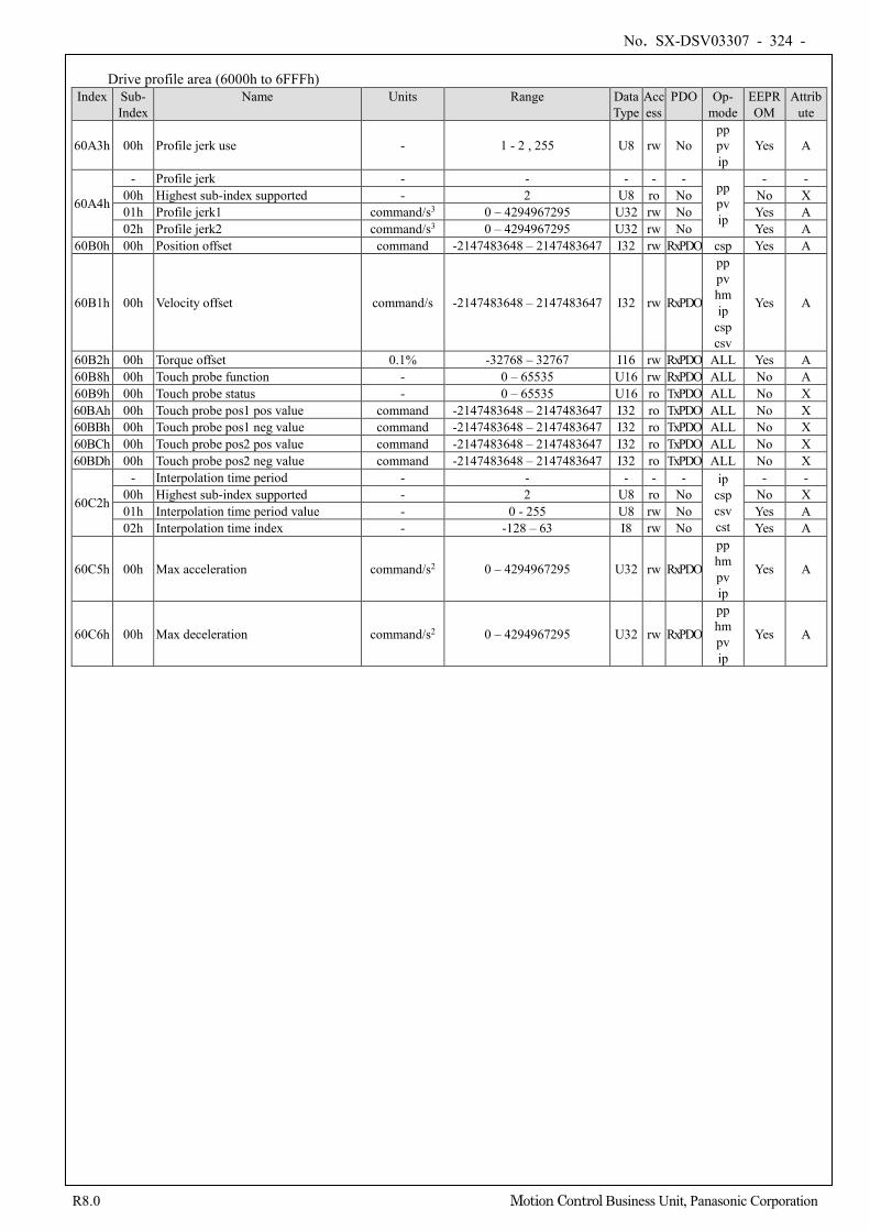
No. SX-DSV03307 - 324 -
R8.0 Motion Control Business Unit, Panasonic Corporation
Drive profile area (6000h to 6FFFh)
Index Sub- Index
Name Units Range Data Type
Access
PDO Op- mode
EEPROM
Attribute
60A3h 00h Profile jerk use - 1 - 2 , 255 U8 rw No pp pv ip
Yes A
60A4h
- Profile jerk - - - - - pp pv ip
- - 00h Highest sub-index supported - 2 U8 ro No No X 01h Profile jerk1 command/s3 0 – 4294967295 U32 rw No Yes A 02h Profile jerk2 command/s3 0 – 4294967295 U32 rw No Yes A
60B0h 00h Position offset command -2147483648 – 2147483647 I32 rw RxPDO csp Yes A
60B1h 00h Velocity offset command/s -2147483648 – 2147483647 I32 rw RxPDO
pp pv hm ip
csp csv
Yes A
60B2h 00h Torque offset 0.1% -32768 – 32767 I16 rw RxPDO ALL Yes A 60B8h 00h Touch probe function - 0 – 65535 U16 rw RxPDO ALL No A 60B9h 00h Touch probe status - 0 – 65535 U16 ro TxPDO ALL No X 60BAh 00h Touch probe pos1 pos value command -2147483648 – 2147483647 I32 ro TxPDO ALL No X 60BBh 00h Touch probe pos1 neg value command -2147483648 – 2147483647 I32 ro TxPDO ALL No X 60BCh 00h Touch probe pos2 pos value command -2147483648 – 2147483647 I32 ro TxPDO ALL No X 60BDh 00h Touch probe pos2 neg value command -2147483648 – 2147483647 I32 ro TxPDO ALL No X
60C2h
- Interpolation time period - - - - - ip csp csv cst
- - 00h Highest sub-index supported - 2 U8 ro No No X 01h Interpolation time period value - 0 - 255 U8 rw No Yes A 02h Interpolation time index - -128 – 63 I8 rw No Yes A
60C5h 00h Max acceleration command/s2 0 – 4294967295 U32 rw RxPDO
pp hm pv ip
Yes A
60C6h 00h Max deceleration command/s2 0 – 4294967295 U32 rw RxPDO
pp hm pv ip
Yes A
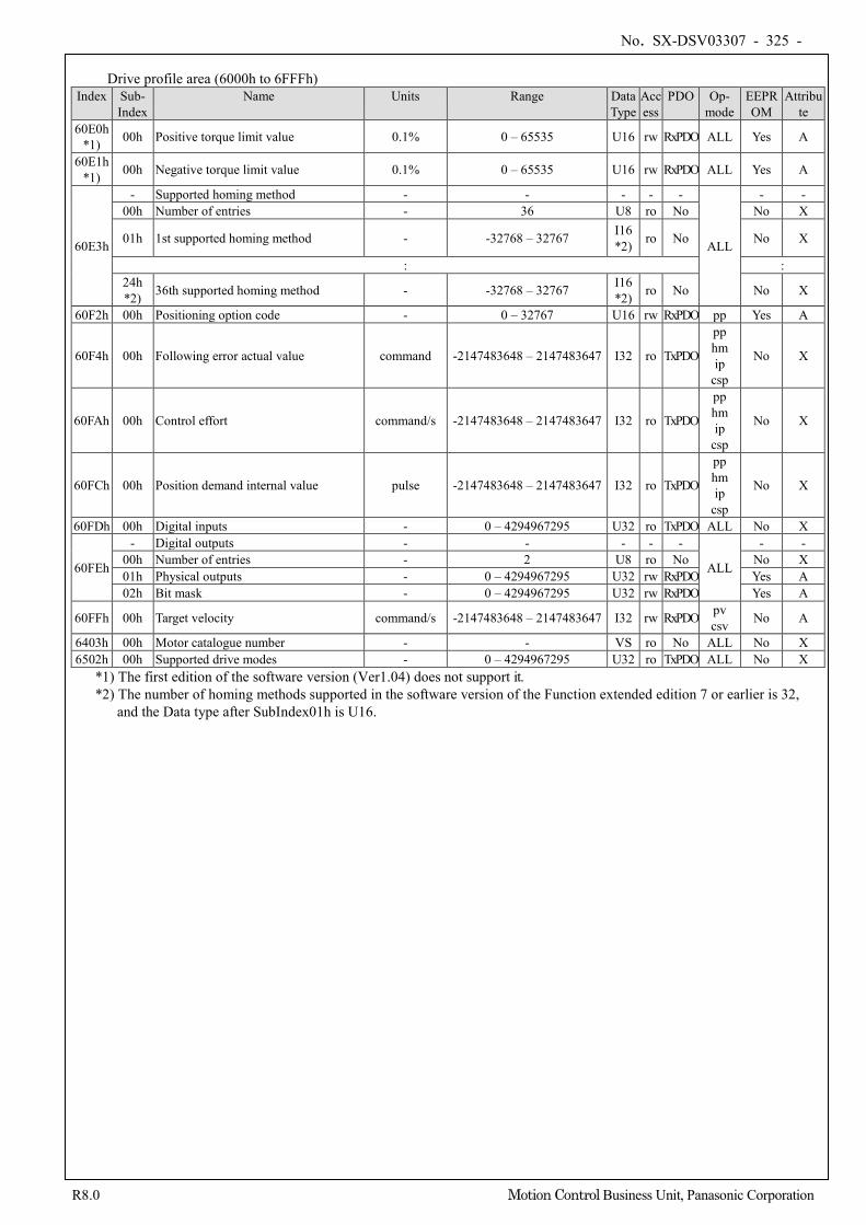
No. SX-DSV03307 - 325 -
R8.0 Motion Control Business Unit, Panasonic Corporation
Drive profile area (6000h to 6FFFh)
Index Sub- Index
Name Units Range Data Type
Access
PDO Op- mode
EEPROM
Attribute
60E0h *1) 00h Positive torque limit value 0.1% 0 – 65535 U16 rw RxPDO ALL Yes A
60E1h *1) 00h Negative torque limit value 0.1% 0 – 65535 U16 rw RxPDO ALL Yes A
60E3h
- Supported homing method - - - - -
ALL
- - 00h Number of entries - 36 U8 ro No No X
01h 1st supported homing method - -32768 – 32767 I16 *2) ro No No X
: : 24h *2) 36th supported homing method - -32768 – 32767 I16
*2) ro No No X
60F2h 00h Positioning option code - 0 – 32767 U16 rw RxPDO pp Yes A
60F4h 00h Following error actual value command -2147483648 – 2147483647 I32 ro TxPDO
pp hm ip
csp
No X
60FAh 00h Control effort command/s -2147483648 – 2147483647 I32 ro TxPDO
pp hm ip
csp
No X
60FCh 00h Position demand internal value pulse -2147483648 – 2147483647 I32 ro TxPDO
pp hm ip
csp
No X
60FDh 00h Digital inputs - 0 – 4294967295 U32 ro TxPDO ALL No X
60FEh
- Digital outputs - - - - -
ALL
- - 00h Number of entries - 2 U8 ro No No X 01h Physical outputs - 0 – 4294967295 U32 rw RxPDO Yes A 02h Bit mask - 0 – 4294967295 U32 rw RxPDO Yes A
60FFh 00h Target velocity command/s -2147483648 – 2147483647 I32 rw RxPDO pv csv No A
6403h 00h Motor catalogue number - - VS ro No ALL No X 6502h 00h Supported drive modes - 0 – 4294967295 U32 ro TxPDO ALL No X
*1) The first edition of the software version (Ver1.04) does not support it. *2) The number of homing methods supported in the software version of the Function extended edition 7 or earlier is 32,
and the Data type after SubIndex01h is U16.
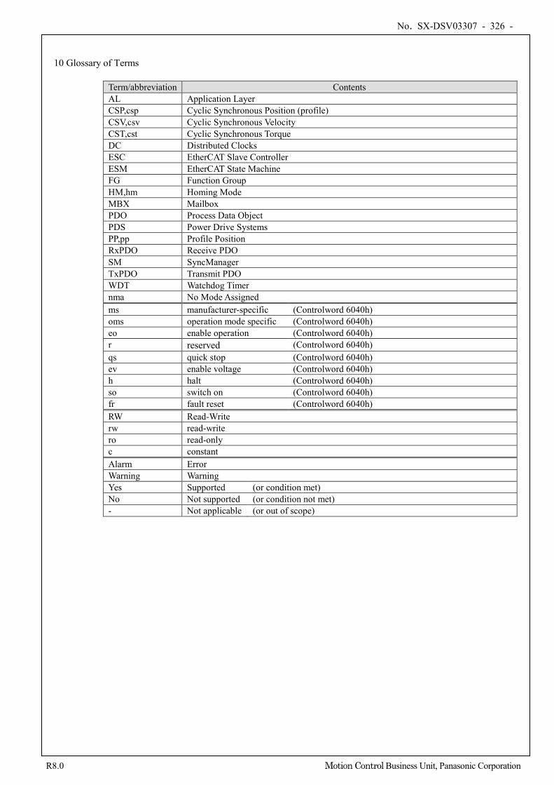
No. SX-DSV03307 - 326 -
R8.0 Motion Control Business Unit, Panasonic Corporation
10 Glossary of Terms
Term/abbreviation Contents AL Application Layer CSP,csp Cyclic Synchronous Position (profile) CSV,csv Cyclic Synchronous Velocity CST,cst Cyclic Synchronous Torque DC Distributed Clocks ESC EtherCAT Slave Controller ESM EtherCAT State Machine FG Function Group HM,hm Homing Mode MBX Mailbox PDO Process Data Object PDS Power Drive Systems PP,pp Profile Position RxPDO Receive PDO SM SyncManager TxPDO Transmit PDO WDT Watchdog Timer nma No Mode Assigned ms manufacturer-specific (Controlword 6040h) oms operation mode specific (Controlword 6040h) eo enable operation (Controlword 6040h) r reserved (Controlword 6040h) qs quick stop (Controlword 6040h) ev enable voltage (Controlword 6040h) h halt (Controlword 6040h) so switch on (Controlword 6040h) fr fault reset (Controlword 6040h) RW Read-Write rw read-write ro read-only c constant Alarm Error Warning Warning Yes Supported (or condition met) No Not supported (or condition not met) - Not applicable (or out of scope)
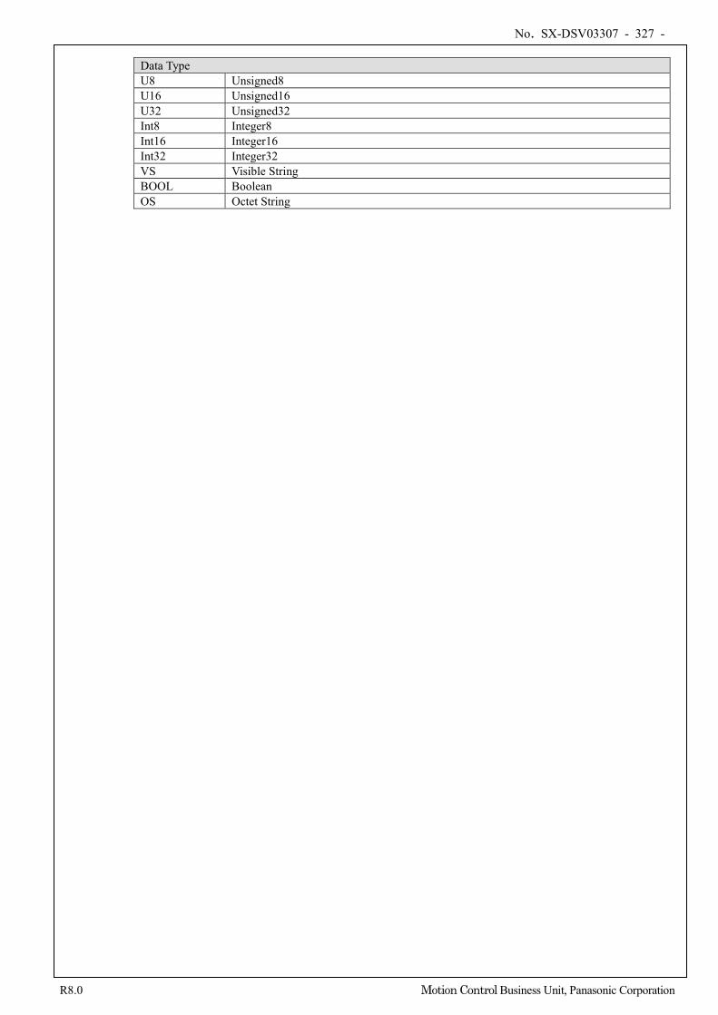
No. SX-DSV03307 - 327 -
R8.0 Motion Control Business Unit, Panasonic Corporation
Data Type U8 Unsigned8 U16 Unsigned16 U32 Unsigned32 Int8 Integer8 Int16 Integer16 Int32 Integer32 VS Visible String BOOL Boolean OS Octet String