Embed Size (px)
Citation preview
29th Aerospace Testing Seminar, October 2015
Significant Attenuation of Lightly Damped Resonances Using Particle
Dampers
Andrew Smith NASA/MSFC/EV31
Bruce LaVerde ERC Inc. /Jacobs ESSSA Contract
Ron Hunt AVNIK Defense Solutions Inc.
Joseph Brent Knight NASA/MSFC/ES22
ABSTRACT
When equipment designs must perform in a broad band vibration environment it can be difficult
to avoid resonances that affect life and performance. This is especially true when an organization
seeks to employ an asset from a heritage design in a new, more demanding vibration environment.
Particle dampers may be used to provide significant attenuation of lightly damped resonances to
assist with such a deployment of assets by including only a very minor set of modifications. This
solution may be easier to implement than more traditional attenuation schemes. Furthermore, the
cost in additional weight to the equipment can be very small. Complexity may also be kept to a
minimum, because the particle dampers do not require tuning. Attenuating the vibratory response
with particle dampers may therefore be simpler (in a set it and forget it kind of way) than tuned
mass dampers. The paper will illustrate the use of an “equivalent resonance test jig” that can assist
designers in verifying the potential resonance attenuation that may be available to them during the
early trade stages of the design. An approach is suggested for transforming observed attenuation
in the jig to estimated performance in the actual service design.
KEY WORDS: Particle Damper, Performance in Vibration Environment, Damping, Resonance,
Attenuation, Mitigation of Vibration Response, Response Estimate, Response Verification.
ACKNOWLEDGMENT
The authors would like to acknowledge the fine support provided by David Geist of MSFC ES43
and also the ET40 test organization at Marshall Space Flight Center (MSFC) who pitched in to
facilitate early proof of concept tests using their vibration shakers and data acquisition equipment.
In addition, the support of Mr. Robert Beard from MSFC ES21, The Space Systems Department
– Thermal and Mechanical Analysis Branch, in providing the finalized designs and machining
necessary to implement our test plans using made to order parts was invaluable. We also
appreciate the MSFC ER35 team, The Thrust Vector Control Systems Integration and Components
Branch, for providing us an interesting challenge. The particle damper demonstrations supported
one of several paths explored to satisfy the program that the STS heritage design Thrust Vector
Control Actuator could be adapted for use in a more severe vibration environment. Special
appreciation is expressed toward the professional team at Moog and Boeing. They have
contributed much to the risk reduction efforts in the way of testing and analytical investigations.
Also their ongoing efforts will provide the TVC actuator support necessary to qualify the design
and integrate it at 8 locations on the SLS vehicle.
29th Aerospace Testing Seminar, October 2015
INTRODUCTION
The vibroacoustics team at MSFC has investigated the effectiveness of particle impact dampers
(PIDs) as a mitigation strategy to attenuate troublesome vibration response in equipment. The
trials conducted with several different test articles successfully indicates that the PIDs can be
very effective at diminishing specific lightly damped resonant modes. In fact, if the resonance
under investigation is “lightly damped” then the team has come to expect a reduction on the
order of 10 dB in resonance magnitude. The addition of this type of mitigation device might be
much less effective for a system resonance that already had significant damping before the PID
was added.
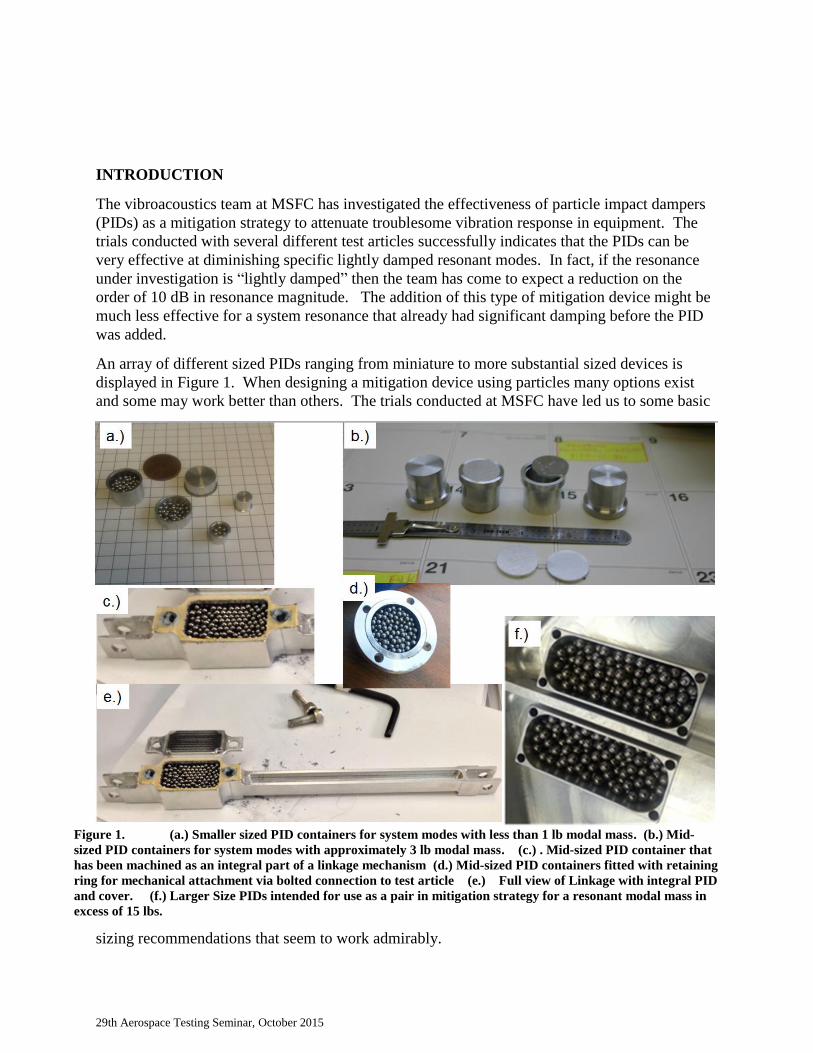
An array of different sized PIDs ranging from miniature to more substantial sized devices is
displayed in Figure 1. When designing a mitigation device using particles many options exist
and some may work better than others. The trials conducted at MSFC have led us to some basic
sizing recommendations that seem to work admirably.
Figure 1. (a.) Smaller sized PID containers for system modes with less than 1 lb modal mass. (b.) Mid-
sized PID containers for system modes with approximately 3 lb modal mass. (c.) . Mid-sized PID container that
has been machined as an integral part of a linkage mechanism (d.) Mid-sized PID containers fitted with retaining
ring for mechanical attachment via bolted connection to test article (e.) Full view of Linkage with integral PID
and cover. (f.) Larger Size PIDs intended for use as a pair in mitigation strategy for a resonant modal mass in
excess of 15 lbs.
29th Aerospace Testing Seminar, October 2015
The recommendation is to select the mode of concern and identify a location near the point of
maximum displacement. Ideally, a PID would be attached to the identified location (maximized
for displacement), and sized such that the weight of the enclosed particles represents 10% of the
mode’s effective mass. Motion of the particles removes energy from the mode of concern for the
vibrating system. The recommendation could likely be further optimized, but these guidelines
serve well as a starting point from which the reader can expect to be effective at attenuating a
specific resonant mode.
BACKGROUND
New launch vehicle programs may be interested in making use of assets that seemed trustworthy
performers in a previous program. They may also want to explore the use of items of
“Commercial off the Shelf” (COTS) design. The Space Launch System (SLS) program has
access to avionics units or propulsion/navigation and control equipment that performed well for
previous launch vehicles. Therefore, an investigation was begun through “development/risk
reduction” testing to ascertain whether or not the existing designs could be used as is (or with
minor modifications)
The possibility of including certain Thrust Vector Control (TVC) actuators of heritage design
was investigated for the propulsion system of the SLS first stage core segment. The function of
the actuators is to adjust and maintain the gimbal orientations of the four RS25 Engines. The
heritage design actuators were originally developed for the space shuttle orbiter. Controlling the
thrust vectors for these engines is part of the overall steering and navigation scheme for the new
vehicle during the first stage phase of flight.
The desire to use the heritage TVC actuator equipment proved to be a challenge because the
vibration environment in which the equipment would have to perform is more demanding than
the previous service environment. The functional performance of the equipment during exposure
to vibration was a matter for verification by test. Several risk reduction tests were conducted in
order to mitigate risk for the program. A final qualification for the designs for all of the SLS
environments is scheduled for the near future.
Results of early development tests indicated that the higher levels of vibration exposure could
result in undesired perturbations of the actuator piston motion. Essentially, a mechanical feeler
gauge used to sense the extensional position of the actuator piston was “being fooled”. The
feeler gauge was used to mechanically report the degree to which the jaws of a scissor element
were open in order to represent the motion of the piston fitted with a conically shaped cam. The
narrowing of the cam as it moved over the scissor jaws indicated that the actuator piston was
retracting into the unit. Conversely, extension of the piston resulted in the opening of the jaws of
the scissors wider as they were pressed against the conical cam.
The TVC design includes a series of coil springs that press the scissor jaws open against the cam.
The risk reduction tests eventually demonstrated that inertial loads became greater than the coil
spring’s resultant force and that caused a loss of contact of the scissors with the cam. This
phenomenon “fooled” the gage. A detailed description of the mechanical system follows.
29th Aerospace Testing Seminar, October 2015
Actuator Operational Details and Functional Perturbation Problem under Vibration:
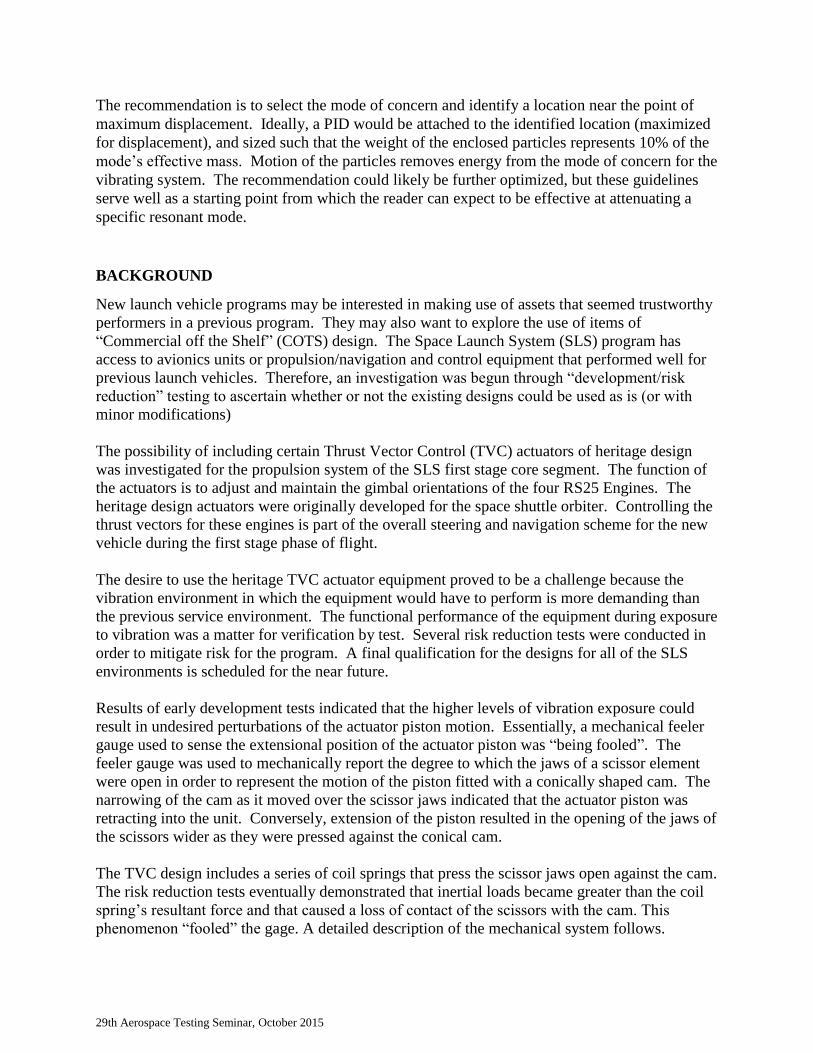
On a basic level, the thrust vector of each liquid rocket engine is controlled using a pair of
hydraulic piston actuators. The forward attachment for the TVC actuator body is through a
pinned connection to the vehicle thrust structures. A piston-driven rod end extends out of the
body’s hydraulic cylinder and interfaces to the engine at another pinned connection. The pitch
and yaw actuators are depicted in relation to the engine and vehicle interfaces in Figure 2.
In order to facilitate the sensing of the rod end position, the movable piston/rod end assembly is
fitted with a long conical cam. The cam interfaces with the mechanical sensing feedback linkage
through a preloaded feeler gauge which has been dubbed the scissors. The scissors press open
against the inside surface of the conical cam via the three coil springs. A cut away view of the
actuator assembly is provided in Figure 3 along with an expanded view with labels describing
elements of the position sensing feedback mechanism.
Figure 2 A pair of hydraulic actuators are used to select and control the thrust vector produced
by the RS25 liquid rocket engines. The actuators span from the vehicle thrust structure to an interface
location approximately aligned with the middle of the engine main combustion chamber.
29th Aerospace Testing Seminar, October 2015
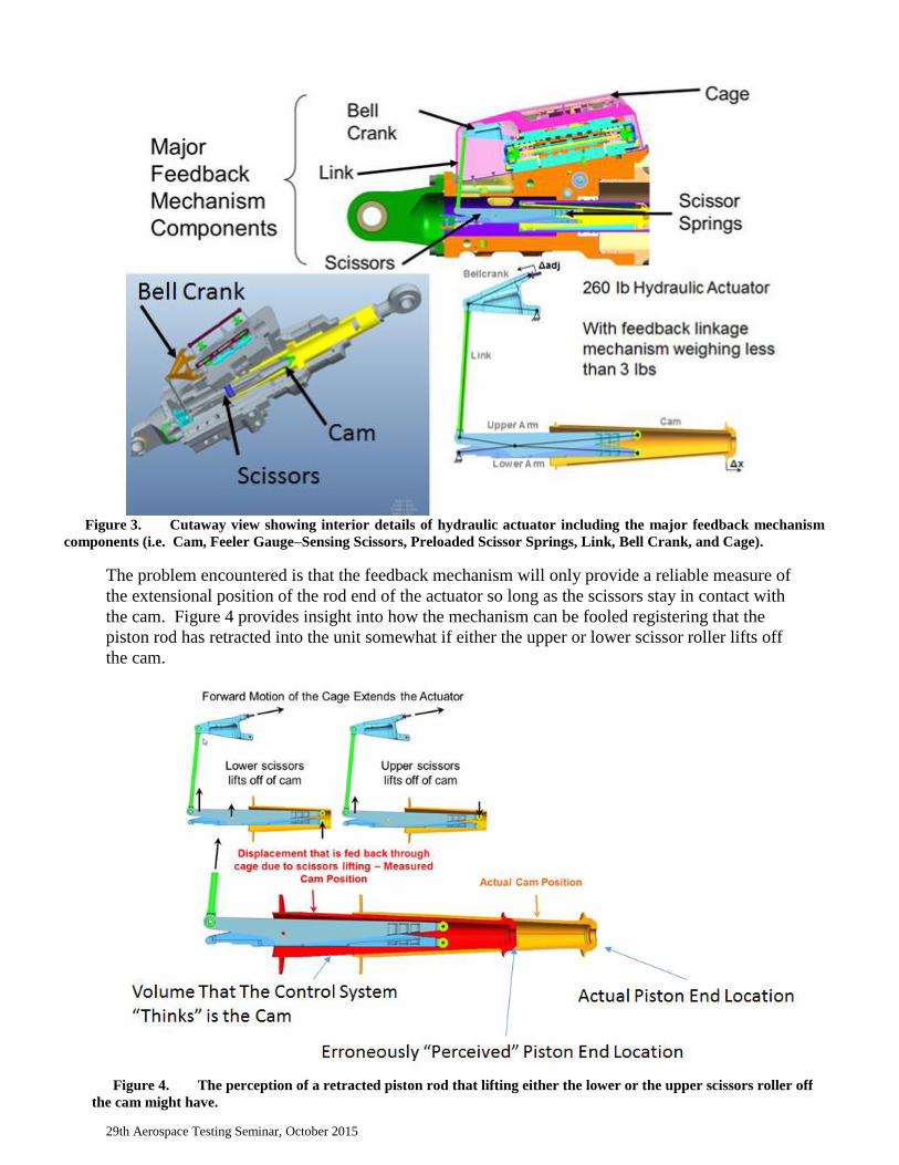
The problem encountered is that the feedback mechanism will only provide a reliable measure of
the extensional position of the rod end of the actuator so long as the scissors stay in contact with
the cam. Figure 4 provides insight into how the mechanism can be fooled registering that the
piston rod has retracted into the unit somewhat if either the upper or lower scissor roller lifts off
the cam.
Figure 3. Cutaway view showing interior details of hydraulic actuator including the major feedback mechanism
components (i.e. Cam, Feeler Gauge–Sensing Scissors, Preloaded Scissor Springs, Link, Bell Crank, and Cage).
Figure 4. The perception of a retracted piston rod that lifting either the lower or the upper scissors roller off
the cam might have.
29th Aerospace Testing Seminar, October 2015
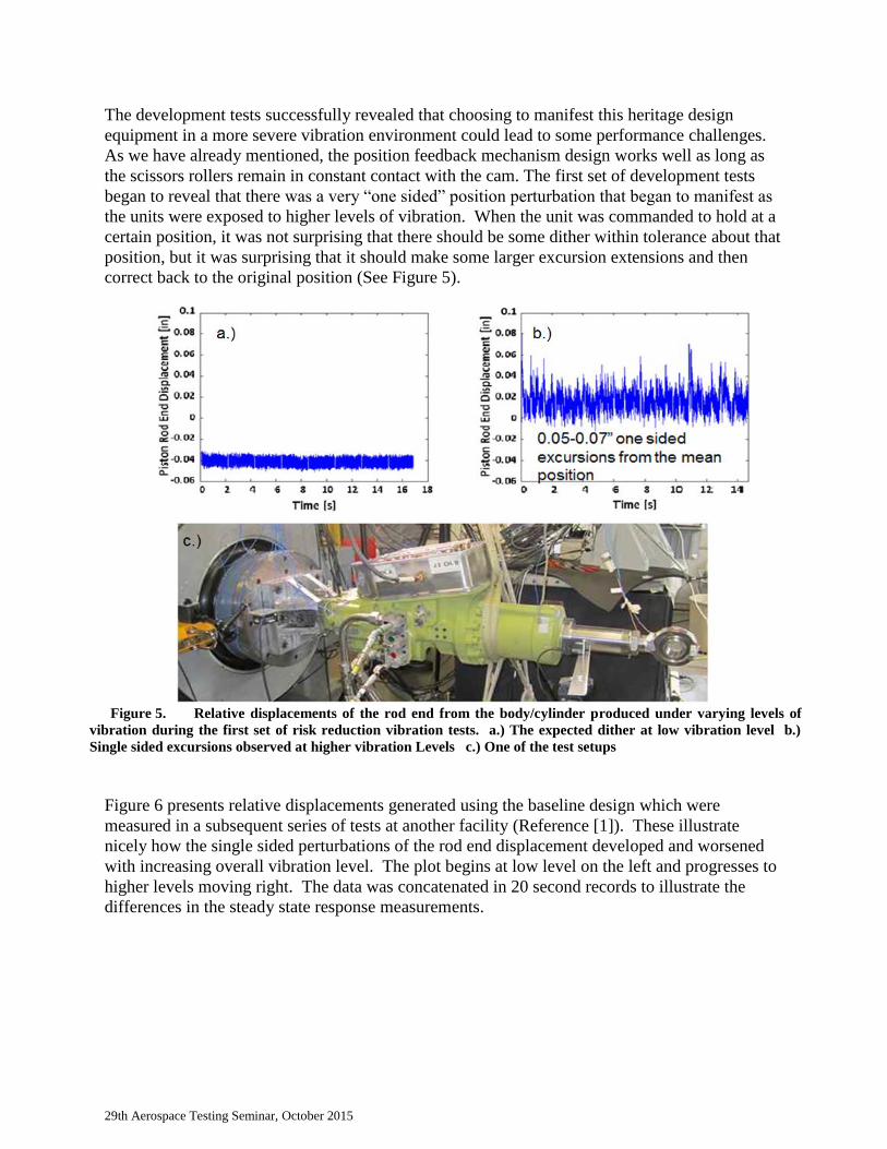
The development tests successfully revealed that choosing to manifest this heritage design
equipment in a more severe vibration environment could lead to some performance challenges.
As we have already mentioned, the position feedback mechanism design works well as long as
the scissors rollers remain in constant contact with the cam. The first set of development tests
began to reveal that there was a very “one sided” position perturbation that began to manifest as
the units were exposed to higher levels of vibration. When the unit was commanded to hold at a
certain position, it was not surprising that there should be some dither within tolerance about that
position, but it was surprising that it should make some larger excursion extensions and then
correct back to the original position (See Figure 5).
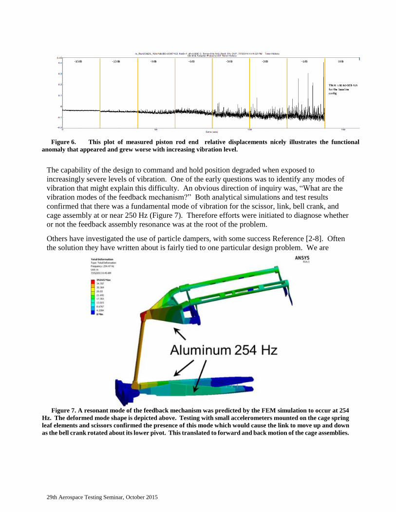
Figure 6 presents relative displacements generated using the baseline design which were
measured in a subsequent series of tests at another facility (Reference [1]). These illustrate
nicely how the single sided perturbations of the rod end displacement developed and worsened
with increasing overall vibration level. The plot begins at low level on the left and progresses to
higher levels moving right. The data was concatenated in 20 second records to illustrate the
differences in the steady state response measurements.
Figure 5. Relative displacements of the rod end from the body/cylinder produced under varying levels of
vibration during the first set of risk reduction vibration tests. a.) The expected dither at low vibration level b.)
Single sided excursions observed at higher vibration Levels c.) One of the test setups
29th Aerospace Testing Seminar, October 2015
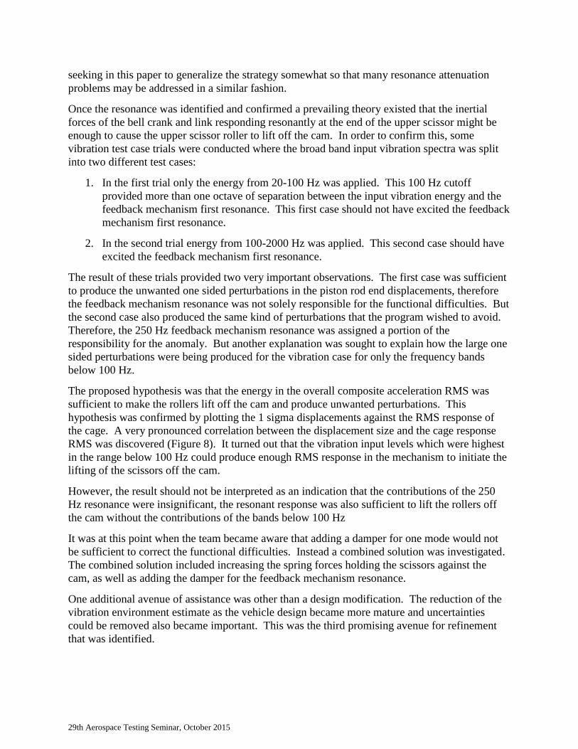
The capability of the design to command and hold position degraded when exposed to
increasingly severe levels of vibration. One of the early questions was to identify any modes of
vibration that might explain this difficulty. An obvious direction of inquiry was, “What are the
vibration modes of the feedback mechanism?” Both analytical simulations and test results
confirmed that there was a fundamental mode of vibration for the scissor, link, bell crank, and
cage assembly at or near 250 Hz (Figure 7). Therefore efforts were initiated to diagnose whether
or not the feedback assembly resonance was at the root of the problem.
Others have investigated the use of particle dampers, with some success Reference [2-8]. Often
the solution they have written about is fairly tied to one particular design problem. We are
Figure 6. This plot of measured piston rod end relative displacements nicely illustrates the functional
anomaly that appeared and grew worse with increasing vibration level.
Figure 7. A resonant mode of the feedback mechanism was predicted by the FEM simulation to occur at 254
Hz. The deformed mode shape is depicted above. Testing with small accelerometers mounted on the cage spring
leaf elements and scissors confirmed the presence of this mode which would cause the link to move up and down
as the bell crank rotated about its lower pivot. This translated to forward and back motion of the cage assemblies.
29th Aerospace Testing Seminar, October 2015
seeking in this paper to generalize the strategy somewhat so that many resonance attenuation
problems may be addressed in a similar fashion.
Once the resonance was identified and confirmed a prevailing theory existed that the inertial
forces of the bell crank and link responding resonantly at the end of the upper scissor might be
enough to cause the upper scissor roller to lift off the cam. In order to confirm this, some
vibration test case trials were conducted where the broad band input vibration spectra was split
into two different test cases:
1. In the first trial only the energy from 20-100 Hz was applied. This 100 Hz cutoff
provided more than one octave of separation between the input vibration energy and the
feedback mechanism first resonance. This first case should not have excited the feedback
mechanism first resonance.
2. In the second trial energy from 100-2000 Hz was applied. This second case should have
excited the feedback mechanism first resonance.
The result of these trials provided two very important observations. The first case was sufficient
to produce the unwanted one sided perturbations in the piston rod end displacements, therefore
the feedback mechanism resonance was not solely responsible for the functional difficulties. But
the second case also produced the same kind of perturbations that the program wished to avoid.
Therefore, the 250 Hz feedback mechanism resonance was assigned a portion of the
responsibility for the anomaly. But another explanation was sought to explain how the large one
sided perturbations were being produced for the vibration case for only the frequency bands
below 100 Hz.
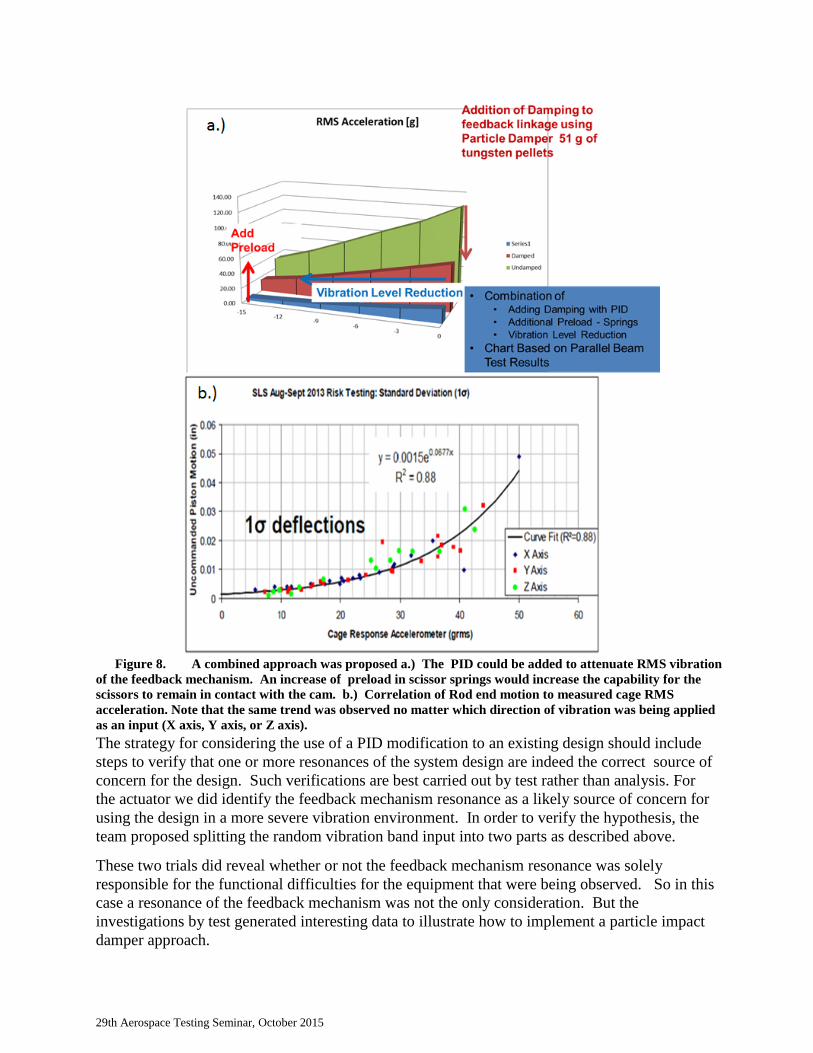
The proposed hypothesis was that the energy in the overall composite acceleration RMS was
sufficient to make the rollers lift off the cam and produce unwanted perturbations. This
hypothesis was confirmed by plotting the 1 sigma displacements against the RMS response of
the cage. A very pronounced correlation between the displacement size and the cage response
RMS was discovered (Figure 8). It turned out that the vibration input levels which were highest
in the range below 100 Hz could produce enough RMS response in the mechanism to initiate the
lifting of the scissors off the cam.
However, the result should not be interpreted as an indication that the contributions of the 250
Hz resonance were insignificant, the resonant response was also sufficient to lift the rollers off
the cam without the contributions of the bands below 100 Hz
It was at this point when the team became aware that adding a damper for one mode would not
be sufficient to correct the functional difficulties. Instead a combined solution was investigated.
The combined solution included increasing the spring forces holding the scissors against the
cam, as well as adding the damper for the feedback mechanism resonance.
One additional avenue of assistance was other than a design modification. The reduction of the
vibration environment estimate as the vehicle design became more mature and uncertainties
could be removed also became important. This was the third promising avenue for refinement
that was identified.
29th Aerospace Testing Seminar, October 2015
The strategy for considering the use of a PID modification to an existing design should include
steps to verify that one or more resonances of the system design are indeed the correct source of
concern for the design. Such verifications are best carried out by test rather than analysis. For
the actuator we did identify the feedback mechanism resonance as a likely source of concern for
using the design in a more severe vibration environment. In order to verify the hypothesis, the
team proposed splitting the random vibration band input into two parts as described above.
These two trials did reveal whether or not the feedback mechanism resonance was solely
responsible for the functional difficulties for the equipment that were being observed. So in this
case a resonance of the feedback mechanism was not the only consideration. But the
investigations by test generated interesting data to illustrate how to implement a particle impact
damper approach.
Figure 8. A combined approach was proposed a.) The PID could be added to attenuate RMS vibration
of the feedback mechanism. An increase of preload in scissor springs would increase the capability for the
scissors to remain in contact with the cam. b.) Correlation of Rod end motion to measured cage RMS
acceleration. Note that the same trend was observed no matter which direction of vibration was being applied
as an input (X axis, Y axis, or Z axis).
29th Aerospace Testing Seminar, October 2015
The added benefit of conducting some tests with the original design before modification is the
ability to determine the damping characteristics of the resonance you would like to affect by
adding a PID to the design. Note that damping characteristics can be nonlinear and dependent on
vibration input levels. This data can be
Once the team has determined that, attenuating a specific resonance may allow them to deploy
the heritage design in the more demanding environment, the next step is to understand what the
mode shape of that resonance is. For this step referring to models may be quite appropriate. The
task is to identify a “location” on the structure that is suitable to attach a container full of
tungsten particles. This location should optimize the motion seen by the container of particles
when the Identified mode responds. The particle container may be attached to existing hardware,
or embedded within a part if desired. The purpose is to locate the package of particles at a
location where they will endure a great deal of motion when the target system mode is excited.
Another aspect of the strategy may be to develop an estimate of the degree to which adding the
particle damper package may help. For this purpose we have added a section describing our use
of a parallel beam test jig. Test data from the jig trials and from development tests with the
original design may be all that is needed to provide a useful initial estimate of attenuation
performance
Equivalent Resonance Test Jig
A jig was devised to allow us to tune an SDOF-like resonance on a shaker table to match both
the modal mass and the natural frequency of our target mode. Two beams were aligned parallel
to one another in a clamped-clamped arrangement with a provision for trim masses and particle
dampers at the midpoints of the beams. Stiffness and mass adjustments can be made by varying
the section modulus of the beams, the distance between the supports, and the amount of trim
mass added at the center. The fastener retaining the trim masses to the beams also included a
feature for attaching particle damper housings. Selection of the available degrees of freedom
(span, cross section, and center mass), was guided by a finite element beam model. Once a
design was chosen that best fit the desired natural frequency and modal mass, one of the dampers
was filled with particles to the prescribed level. This parallel beam arrangement allows for a
comparison between the damped and un-damped responses. Stepping up to the final test level in
increments shows how much damping can be achieved.
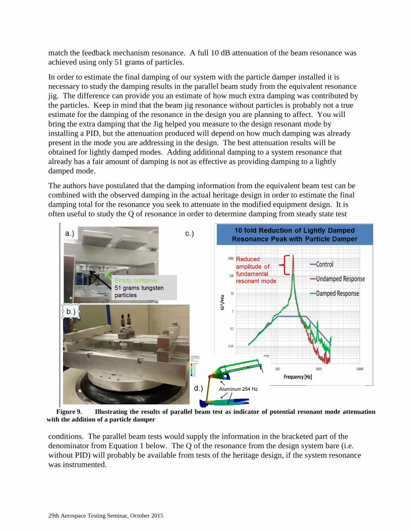
Figure 9 presents results from a vibration trial using such a jig and related to the TVC actuator
problem we have discussed. The resonance frequency and modal mass were chosen to closely
29th Aerospace Testing Seminar, October 2015
match the feedback mechanism resonance. A full 10 dB attenuation of the beam resonance was
achieved using only 51 grams of particles.
In order to estimate the final damping of our system with the particle damper installed it is
necessary to study the damping results in the parallel beam study from the equivalent resonance
jig. The difference can provide you an estimate of how much extra damping was contributed by
the particles. Keep in mind that the beam jig resonance without particles is probably not a true
estimate for the damping of the resonance in the design you are planning to affect. You will
bring the extra damping that the Jig helped you measure to the design resonant mode by
installing a PID, but the attenuation produced will depend on how much damping was already
present in the mode you are addressing in the design. The best attenuation results will be
obtained for lightly damped modes. Adding additional damping to a system resonance that
already has a fair amount of damping is not as effective as providing damping to a lightly
damped mode.
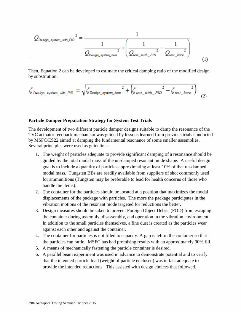
The authors have postulated that the damping information from the equivalent beam test can be
combined with the observed damping in the actual heritage design in order to estimate the final
damping total for the resonance you seek to attenuate in the modified equipment design. It is
often useful to study the Q of resonance in order to determine damping from steady state test
conditions. The parallel beam tests would supply the information in the bracketed part of the
denominator from Equation 1 below. The Q of the resonance from the design system bare (i.e.
without PID) will probably be available from tests of the heritage design, if the system resonance
was instrumented.
Figure 9. Illustrating the results of parallel beam test as indicator of potential resonant mode attenuation
with the addition of a particle damper
29th Aerospace Testing Seminar, October 2015
` (1)
Then, Equation 2 can be developed to estimate the critical damping ratio of the modified design
by substitution:
(2)
Particle Damper Preparation Strategy for System Test Trials
The development of two different particle damper designs suitable to damp the resonance of the
TVC actuator feedback mechanism was guided by lessons learned from previous trials conducted
by MSFC/ES22 aimed at damping the fundamental resonance of some smaller assemblies.
Several principles were used as guidelines:
1. The weight of particles adequate to provide significant damping of a resonance should be
guided by the total modal mass of the un-damped resonant mode shape. A useful design
goal is to include a quantity of particles approximating at least 10% of that un-damped
modal mass. Tungsten BBs are readily available from suppliers of shot commonly used
for ammunitions (Tungsten may be preferable to lead for health concerns of those who
handle the items).
2. The container for the particles should be located at a position that maximizes the modal
displacements of the package with particles. The more the package participates in the
vibration motions of the resonant mode targeted for reductions the better.
3. Design measures should be taken to prevent Foreign Object Debris (FOD) from escaping
the container during assembly, disassembly, and operation in the vibration environment.
In addition to the small particles themselves, a fine dust is created as the particles wear
against each other and against the container.
4. The container for particles is not filled to capacity. A gap is left in the container so that
the particles can rattle. MSFC has had promising results with an approximately 90% fill.
5. A means of mechanically fastening the particle container is desired.
6. A parallel beam experiment was used in advance to demonstrate potential and to verify
that the intended particle load (weight of particle enclosed) was in fact adequate to
provide the intended reductions. This assisted with design choices that followed.
29th Aerospace Testing Seminar, October 2015
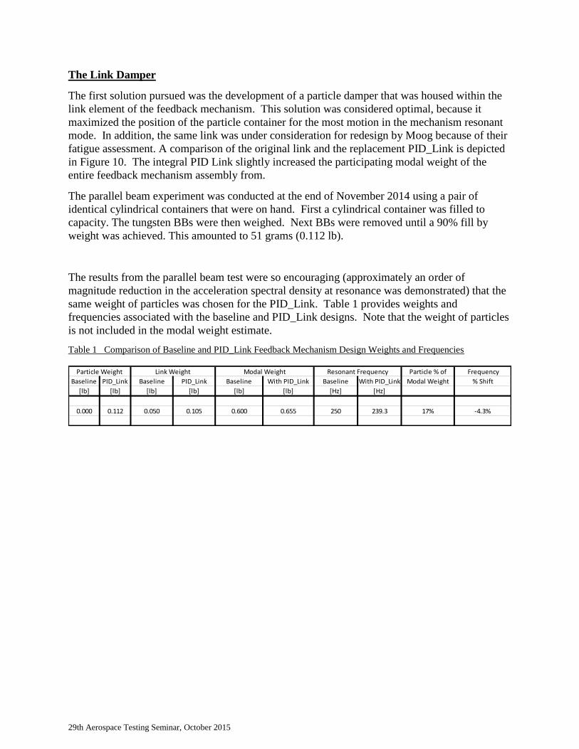
The Link Damper
The first solution pursued was the development of a particle damper that was housed within the
link element of the feedback mechanism. This solution was considered optimal, because it
maximized the position of the particle container for the most motion in the mechanism resonant
mode. In addition, the same link was under consideration for redesign by Moog because of their
fatigue assessment. A comparison of the original link and the replacement PID_Link is depicted
in Figure 10. The integral PID Link slightly increased the participating modal weight of the
entire feedback mechanism assembly from.
The parallel beam experiment was conducted at the end of November 2014 using a pair of
identical cylindrical containers that were on hand. First a cylindrical container was filled to
capacity. The tungsten BBs were then weighed. Next BBs were removed until a 90% fill by
weight was achieved. This amounted to 51 grams (0.112 lb).
The results from the parallel beam test were so encouraging (approximately an order of
magnitude reduction in the acceleration spectral density at resonance was demonstrated) that the
same weight of particles was chosen for the PID_Link. Table 1 provides weights and
frequencies associated with the baseline and PID_Link designs. Note that the weight of particles
is not included in the modal weight estimate.
Table 1 Comparison of Baseline and PID_Link Feedback Mechanism Design Weights and Frequencies
Particle % of Frequency
Baseline PID_Link Baseline PID_Link Baseline With PID_Link Baseline With PID_Link Modal Weight % Shift
[lb] [lb] [lb] [lb] [lb] [lb] [Hz] [Hz]
0.000 0.112 0.050 0.105 0.600 0.655 250 239.3 17% -4.3%
Modal WeightLink WeightParticle Weight Resonant Frequency
29th Aerospace Testing Seminar, October 2015
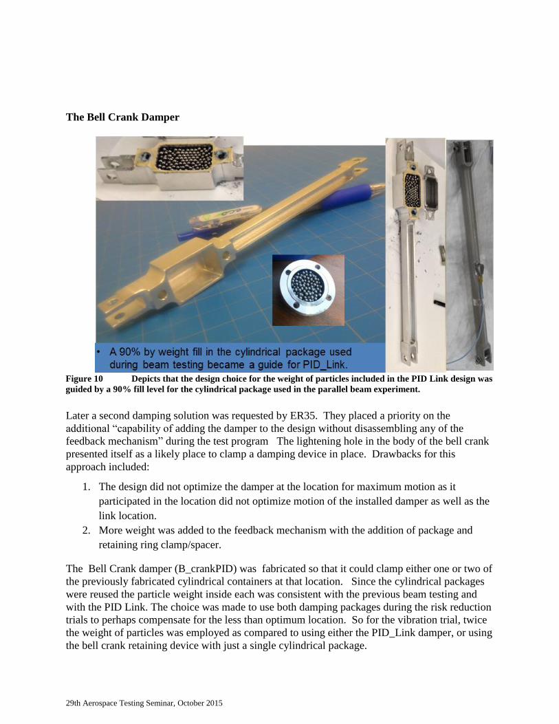
The Bell Crank Damper
Later a second damping solution was requested by ER35. They placed a priority on the
additional “capability of adding the damper to the design without disassembling any of the
feedback mechanism” during the test program The lightening hole in the body of the bell crank
presented itself as a likely place to clamp a damping device in place. Drawbacks for this
approach included:
1. The design did not optimize the damper at the location for maximum motion as it
participated in the location did not optimize motion of the installed damper as well as the
link location.
2. More weight was added to the feedback mechanism with the addition of package and
retaining ring clamp/spacer.
The Bell Crank damper (B_crankPID) was fabricated so that it could clamp either one or two of
the previously fabricated cylindrical containers at that location. Since the cylindrical packages
were reused the particle weight inside each was consistent with the previous beam testing and
with the PID Link. The choice was made to use both damping packages during the risk reduction
trials to perhaps compensate for the less than optimum location. So for the vibration trial, twice
the weight of particles was employed as compared to using either the PID_Link damper, or using
the bell crank retaining device with just a single cylindrical package.
Figure 10 Depicts that the design choice for the weight of particles included in the PID Link design was
guided by a 90% fill level for the cylindrical package used in the parallel beam experiment.
29th Aerospace Testing Seminar, October 2015
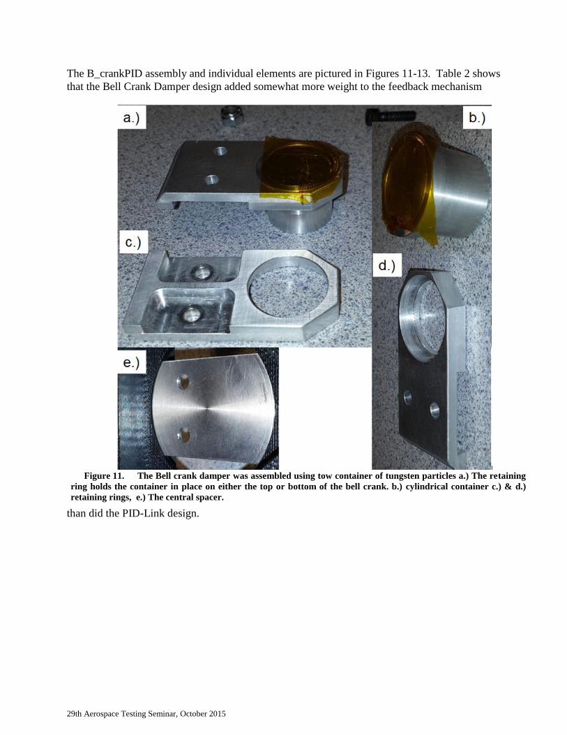
The B_crankPID assembly and individual elements are pictured in Figures 11-13. Table 2 shows
that the Bell Crank Damper design added somewhat more weight to the feedback mechanism
than did the PID-Link design.
Figure 11. The Bell crank damper was assembled using tow container of tungsten particles a.) The retaining
ring holds the container in place on either the top or bottom of the bell crank. b.) cylindrical container c.) & d.)
retaining rings, e.) The central spacer.
29th Aerospace Testing Seminar, October 2015
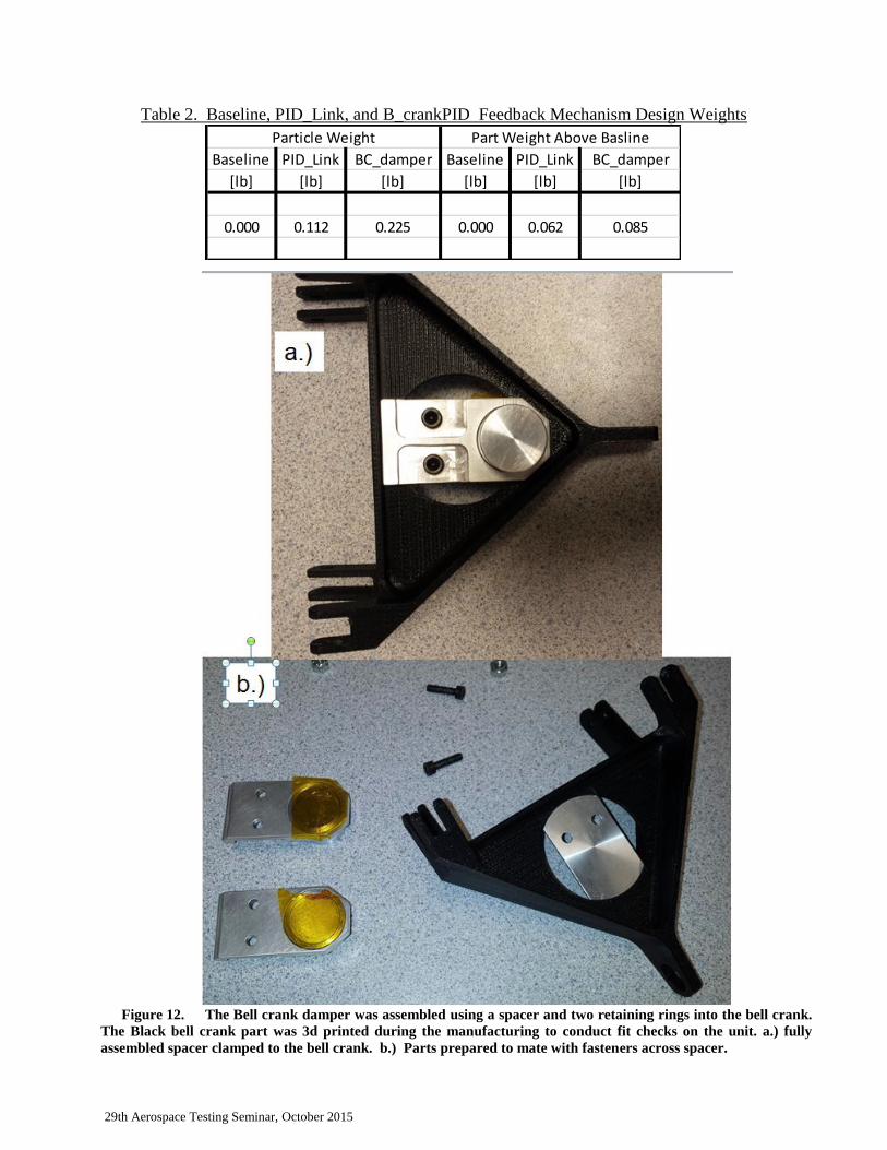
Table 2. Baseline, PID_Link, and B_crankPID Feedback Mechanism Design Weights
Baseline PID_Link BC_damper Baseline PID_Link BC_damper
[lb] [lb] [lb] [lb] [lb] [lb]
0.000 0.112 0.225 0.000 0.062 0.085
Particle Weight Part Weight Above Basline
Figure 12. The Bell crank damper was assembled using a spacer and two retaining rings into the bell crank.
The Black bell crank part was 3d printed during the manufacturing to conduct fit checks on the unit. a.) fully
assembled spacer clamped to the bell crank. b.) Parts prepared to mate with fasteners across spacer.
29th Aerospace Testing Seminar, October 2015
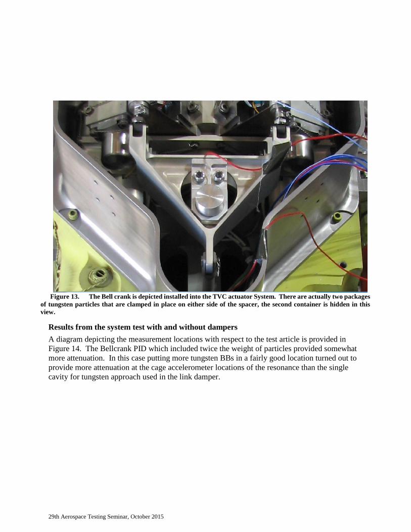
Results from the system test with and without dampers
A diagram depicting the measurement locations with respect to the test article is provided in
Figure 14. The Bellcrank PID which included twice the weight of particles provided somewhat
more attenuation. In this case putting more tungsten BBs in a fairly good location turned out to
provide more attenuation at the cage accelerometer locations of the resonance than the single
cavity for tungsten approach used in the link damper.
Figure 13. The Bell crank is depicted installed into the TVC actuator System. There are actually two packages
of tungsten particles that are clamped in place on either side of the spacer, the second container is hidden in this
view.
29th Aerospace Testing Seminar, October 2015
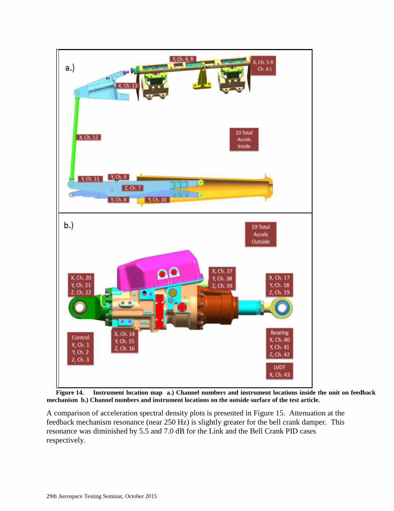
A comparison of acceleration spectral density plots is presented in Figure 15. Attenuation at the
feedback mechanism resonance (near 250 Hz) is slightly greater for the bell crank damper. This
resonance was diminished by 5.5 and 7.0 dB for the Link and the Bell Crank PID cases
respectively.
Figure 14. Instrument location map a.) Channel numbers and instrument locations inside the unit on feedback
mechanism b.) Channel numbers and instrument locations on the outside surface of the test article.
29th Aerospace Testing Seminar, October 2015
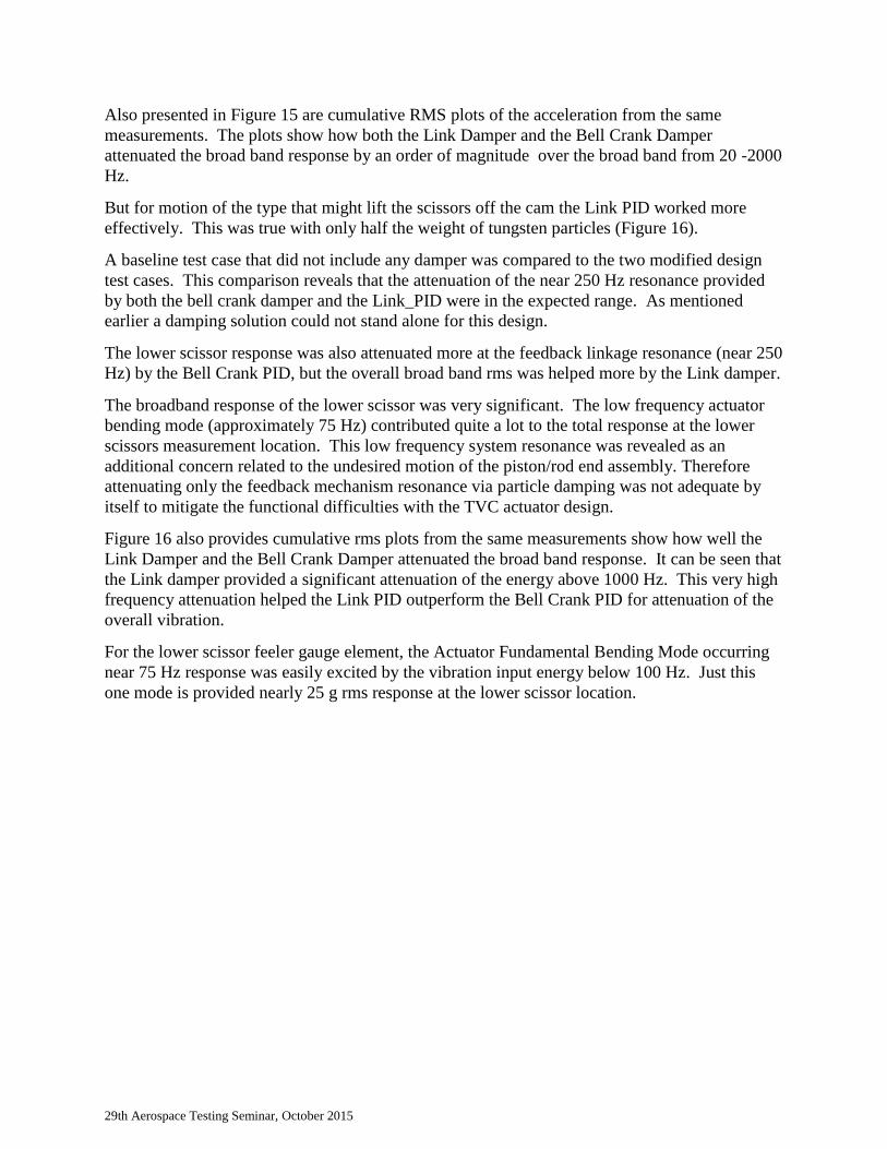
Also presented in Figure 15 are cumulative RMS plots of the acceleration from the same
measurements. The plots show how both the Link Damper and the Bell Crank Damper
attenuated the broad band response by an order of magnitude over the broad band from 20 -2000
Hz.
But for motion of the type that might lift the scissors off the cam the Link PID worked more
effectively. This was true with only half the weight of tungsten particles (Figure 16).
A baseline test case that did not include any damper was compared to the two modified design
test cases. This comparison reveals that the attenuation of the near 250 Hz resonance provided
by both the bell crank damper and the Link_PID were in the expected range. As mentioned
earlier a damping solution could not stand alone for this design.
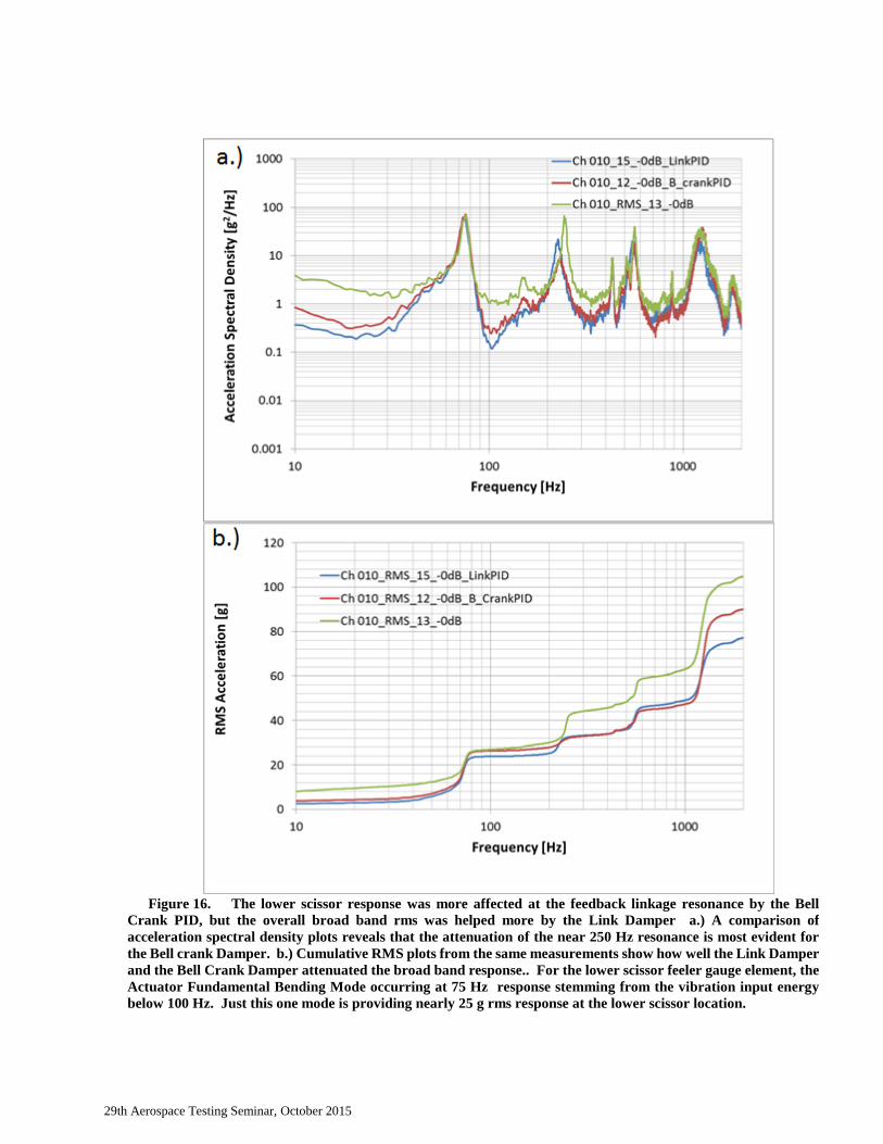
The lower scissor response was also attenuated more at the feedback linkage resonance (near 250
Hz) by the Bell Crank PID, but the overall broad band rms was helped more by the Link damper.
The broadband response of the lower scissor was very significant. The low frequency actuator
bending mode (approximately 75 Hz) contributed quite a lot to the total response at the lower
scissors measurement location. This low frequency system resonance was revealed as an
additional concern related to the undesired motion of the piston/rod end assembly. Therefore
attenuating only the feedback mechanism resonance via particle damping was not adequate by
itself to mitigate the functional difficulties with the TVC actuator design.
Figure 16 also provides cumulative rms plots from the same measurements show how well the
Link Damper and the Bell Crank Damper attenuated the broad band response. It can be seen that
the Link damper provided a significant attenuation of the energy above 1000 Hz. This very high
frequency attenuation helped the Link PID outperform the Bell Crank PID for attenuation of the
overall vibration.
For the lower scissor feeler gauge element, the Actuator Fundamental Bending Mode occurring
near 75 Hz response was easily excited by the vibration input energy below 100 Hz. Just this
one mode is provided nearly 25 g rms response at the lower scissor location.
29th Aerospace Testing Seminar, October 2015
Figure 15. a.) A comparison of acceleration spectral density plots depicts that the attenuation at the 250 Hz
resonance is slightly greater for the Bell Crank Damper. The feedback mechanism resonance (near 250 Hz) was
diminished by 5.5 and 7 dB for the Link and the Bell Crank PID cases respectively. b.) Cumulative RMS plots
from the same measurements show that both the Link Damper and the Bell crank damper attenuated the broad
band response by an order of magnitude over the broad band from 20 -2000 Hz.
29th Aerospace Testing Seminar, October 2015
Figure 16. The lower scissor response was more affected at the feedback linkage resonance by the Bell
Crank PID, but the overall broad band rms was helped more by the Link Damper a.) A comparison of
acceleration spectral density plots reveals that the attenuation of the near 250 Hz resonance is most evident for
the Bell crank Damper. b.) Cumulative RMS plots from the same measurements show how well the Link Damper
and the Bell Crank Damper attenuated the broad band response.. For the lower scissor feeler gauge element, the
Actuator Fundamental Bending Mode occurring at 75 Hz response stemming from the vibration input energy
below 100 Hz. Just this one mode is providing nearly 25 g rms response at the lower scissor location.
29th Aerospace Testing Seminar, October 2015
Conclusions
TVC had functional anomalies that were first theorized to stem from a 250 Hz resonance.
Instrumenting the unit internally so that the response of the feedback mechanism could be
understood in risk reduction testing was an important step in verifying this hypothesis. The
testing revealed that the 250 Hz resonance was not the only concern related to the functional
anomalies that were observed in the demanding vibration environment.
Diagnostic tests used the technique of band splitting to isolate the 250 Hz resonance from the
low frequency broad band energy. This set of test trials showed that the 250 Hz resonance was
not the only problem.
Band splitting as a diagnostic to determine whether the resonance in question is the only source
of concern is a highly recommended technique. If other concerns exist, then the need to seek a
combined solution in order to deploy an older design in a new more demanding vibration
environment may be advised.
Solving the TVC actuator design issues required a combined approach. Ultimately the test
program demonstrated that the particle dampers could supply substantial reduction in the
response of a targeted system resonance.
In the end the second issue “Inertia loads from low frequency bands that overcame the feeler
gauge mechanism preload”, was the dominant source of functional anomalies.
In other designs a resonance may be the dominant source, the PID mitigation strategy remains an
important tool in the hands of engineers seeking to deploy heritage designs in even more
demanding broad band vibration environments.
NASA – REFERENCES
1. Parisa, R., Maehlmann, R., Stuart, B., Laverde, B., Hunt, R., Dehaye, M., et al, “SLS Core
Stage TVC Actuator Risk Mitigation Vibration Test Report,” ER35/TVC System
Integration and Components Branch, July 2014.
2. Fowler, B.L, Flint, E.M., Olson, S.E., “Effectiveness and Predictability of Particle
Damping,” Proceedings of SPIE Volume 3989, Smart Structures and Materials 2000,
Damping and Isolation.
3. Fowler, B.L, Flint, E.M., Olson, S.E., “Design Methodology for Particle Damping,”
Proceedings of SPIE Volume 4331, Smart Structures and Materials 2001, Damping and
Isolation.
4. Friend, R.D. and Kinra, V.K., “Measurement and analysis of particle impact damping,”
Proceedings of SPIE Conf. On Passive Damping and Isolation, 20 – 31, Newport Beach,
CA, March 1999.
5. Hollkamp, J.J. and Gordan, R.W., “Experiments with particle damping,” Passive Damping
and Isolation, Proceedings of SPIE, Vol. 3327, 2 – 12, San Diego, CA, March 1998.
6. Panossian, H. “Non-Obstructive Particle Damping Experience and Capabilities,” The
Boeing Company - Rocketdyne Propulsion & Power, Proceedings of Damping’93, 1993,
pp. ABB, 1 – 56.
29th Aerospace Testing Seminar, October 2015
7. Papalou, A., and S.F. Masri, “Response of Impact Dampers with Granular Materials Under
Random Excitation,” Earthquake Engineering & Structural Dynamics ,March 1996
8. Zhi Wei Xua, K.W. Chan and W.H. Liao,”An empirical method for particle damping
Design” Shock and Vibration 11 (2004) 647–664.
BIOGRAPHIES
Andrew Smith – NASA – MS Mechanical Engineering, Tennessee Technological University –
Currently providing NASA-Marshall Space Flight Center with Vehicle Vibroacoustics support
and leadership. He is the chief investigator for a series of Acoustic Panel Response Tests at
MSFC. These included observation of attenuation effects stemming from the integration of
flight like avionics boxes, wire rope isolators, particle dampers, and damping due to cable
harnesses. Future work will demonstrate environments for a shelf mounted avionics panel
concept. Andrew’s duties include processing and analysis of the measured data as well as
developing vibration, internal acoustic, and shock environments for the SLS launch
vehicle. Email – [email protected]
Ron Hunt - Avnik Defense Solutions Inc. , MS Mechanical Engineering, University of
California, Davis. Ron is a structural analysis engineer supporting the Aviation and Missile
Research, Development, and Engineering Center in the field of Damage Prognostics and
Structural Health Monitoring. His background is in the dynamic analysis and testing of aircraft,
satellites, and launch vehicles but he has a special interest in finite element analysis performed in
Matlab. Email – [email protected]
J. Brent Knight - received a B.S. Degree in Mechanical Engineering (1986) as well as a Masters
Degree in Mechanical Engineering (1988) from Mississippi State University with a focus in the
design and analysis of mechanical systems. He also received a M.S. Degree in Biological
Engineering from Clemson University (1999) where a measurement system was developed to
measure mechanical stiffness of a human spine during a spinal surgery. Brent is employed by
NASA Marshall Space Flight Center and serves as the Space Systems Department’s lead for loads
and dynamics, and is the Technical Assistant for the Thermal and Mechanical Analysis Branch.
He has worked in the area of structural loads and dynamics since 1988. His primary efforts have
been in the area of Coupled Loads Analyses, component Random Vibration Loads, and micro-
gravity analyses. Current efforts and research are in the areas of analytical predictions of mirror
mechanical stability, methodologies to mitigate undue conservatism in structural design loads,
development of shock & vibration mitigation devices, and multi-discipline engineering
development. Prior to his current NASA position he was employed by Boeing, McDonnell
Douglas, Teledyne Brown Engineering, and ERC Inc. Programs that Brent supported include the
International Space Station, SPACEHAB, Space Shuttle Main Engine, ARES, SLS, and
AMTD.Email - [email protected]
Bruce LaVerde - ERC Inc. - BS Physics, Clarion University of PA - is an engineer supporting
Marshall Space Flight Center through the ESTS contract. He has 27 years experience providing
29th Aerospace Testing Seminar, October 2015
response estimates for random vibration and has conducted acoustic, pyroshock, static fire
propulsion, and flight tests to establish environments. He is an experienced finite element analyst
who has also used statistical energy analysis to produce analytical response estimates of the same.
He has published results using both SEA and Hybrid FEA/SEA. He is interested in the differences
in response resulting from different phase correlated pressure fields. Email -


