Embed Size (px)
Citation preview

The Benefit of Harmonics Current Using a NewTopology of Hybrid Active Power Filter
Hussein Al-bayatyFaculty of Science and Technology
University of PlymouthPlymouth, UK
Marcel AmbrozeFaculty of Science and Technology
University of PlymouthPlymouth, UK
Mohammed Zaki AhmedFaculty of Science and Technology
University of PlymouthPlymouth, UK
Abstract—This paper presents a new idea to benefit of eliminatedharmonics current by using a new topology of hybrid active powerfilter (HAPF) to compensate harmonics current to be sinusoidalin order to feed some loads. The design and simulation of a newthree phase HAPF circuit using a shunt active power filter (APF)connected in parallel with a capacitor (C) line of a (LC) low passfilter (LPF) has been submitted.
The first aim of the new circuit is to use the LPF as a path to passthe fundamental frequency (50 Hz) current and eliminate other highorder frequencies, while APF compensates high order frequenciesand compensate reactive power of the circuit. The second aim isto benefit from the modified wave in the high frequency branch ofLPF to use it as a useful power in order to feed different loads. Inaddition, With this topology, the resonance problem (which usuallyhappens between LPF and the system) will disappear because ofusing of APF in the high frequency branch.
The control circuit has been designed based on the instantaneousreactive power theory. A Clarke transformation equations andhysteresis current controller have been used in the HAPF’s design.The proposed circuit has provided a good harmonic elimination, totalharmonic distortion (THD) reduced, reactive power compensationand a reasonable sinusoidal waveform.
Keywords - Harmonics Elimination, Hybrid Active PowerFilter, Active Power Filter, Passive Filters, Total Harmonic Dis-tortion.
I. INTRODUCTION
The enormous increasing in the use of variable solid stateswitching devices in the commercial sectors and home appli-ances represented in rectifies, personal computers, uninterruptablepower supply (UPS), microwave oven, etc., cause a huge increas-ing of the harmonics level in the power grid. The harmonicsare the main reason of defects such as power losses, excessiveover heating in the transformer winding, poor power factor andineffective power system.
Researchers around the world had used different methods inorder to eliminate the harmonics and get rid of its problems, [1],[2], [3]. However, the idea of taking advantage of the eliminatedharmonics current and convert it to a sinusoidal current in orderto feed different loads, has not been developed yet.
Passive filters is still the most conventional used method due toits simplicity of design, simplicity of control, low cost and varietyof types [4]. The main idea of using passive filters is to benefitfrom the characteristics of the inductor and the capacitor, byproviding low impedance path through XL (for low frequencies)and low impedance through XC (for high frequencies) in order
to take out the harmonic current and grounding it [5]. However,the resonance which happens between the filter impedance andthe grid impedance is still the most significant problem for thepassive filter, also the variability of the nonlinear load operatingconditions could affect the filter performance, also for the highpower applications, passive filter needs to be designed with a highcurrent capability because both the harmonics and fundamentalcurrent components flow into the filter thus, it consumes highpower as losses at low frequency [6].
In order to overcome passive filters’ problems, active fil-ters were invented in 1976 by Gyugyi [3]. APF, has differenttopologies and multiple categories, but mostly use voltage sourceconverters. APF, has a voltage source at the DC bus, which isusually a capacitor, as an energy storage device. In recent years,APF has become popular because of it’s accurate reactive powercompensation and current harmonics elimination ability.
Unfortunately, APF also suffers from many problems whichare the high initial costs, high running costs and the requirementof high power converter ratings. The input and the output powerrating is limited by the power supply voltages and always requirea power for the active device [7].
Hybrid filter, has been invented in order to collect all the advan-tages of two types of filters and conquer their limitations, it is acombination of passive filter with active power filter in one system[7]. In many cases APFs can provide effective compensation, buttheir ratings and costs are much higher compared to the HAPF.The rating of APF element in the HAPF’s combination can bereduced to 5% or about 20% in some cases [8] [9]. In addition,HAPF is less sensitive to parameters variations than passive filterswhen used alone [10].
The loss of power quality under non sinusoidal conditions isbetter characterized by another power definition, the Distortionpower (D) [11].
The researcher in [12] presents a new idea to take advantage ofharmonics current (or the Distortion power) instead of wasting itthrough grounding. The author in [12] has used passive filtersto extract the harmonics from the system and convert theseharmonics to DC current and then reconvert it to sinusoidal ACcurrent. This paper uses the same idea but using a new topologyof HAPF, and submits two main ideas. The first idea of thiscircuit is that while LPF passes the fundamental frequency (50Hz) and eliminates high order frequencies, APF will compensatehigh order frequencies and the reactive power in the circuit. The
second idea is to benefit from the modified current in the capacitorbranch of LPF to use it as a useful power in order to feed differentloads. The nonlinear load is represented by a three phase full wavebridge rectifier and a MOSFET switched by PWM circuit 150Hzswitching frequency in series with small resistor (1Ω) .
The design and simulation of the proposed circuit has beenpresented and tested in Matlab-Simulink program. In the secondsection, an analysis of the new proposed HAPF has been pre-sented. In the third section, instantaneous reactive power theoryand its equations has been formulated. In the fourth section,a three different topologies have been designed and simulated,a comparison between different filters performances has beendone.In the fifth section, hysteresis current control (HCC) circuithas been described. The sixth section shows the specification ofthe design. Finally, simulation results and their conclusions hasbeen discussed.
II. ANALYSIS OF THE NEW CIRCUIT
The new HAPF is a combination of shunt APF connectedin shunt with the capacitor (high frequency) branch of the lowpassive filter (LPF), a single line diagram of the proposed filteris shown in Fig. 1.
Commonly, a parallel APF has been considered as a currentsource, and the nonlinear load as a harmonic source. The com-pensation method is based on the concept of injecting harmoniccurrent with a same magnitude of capacitor current but at a 180
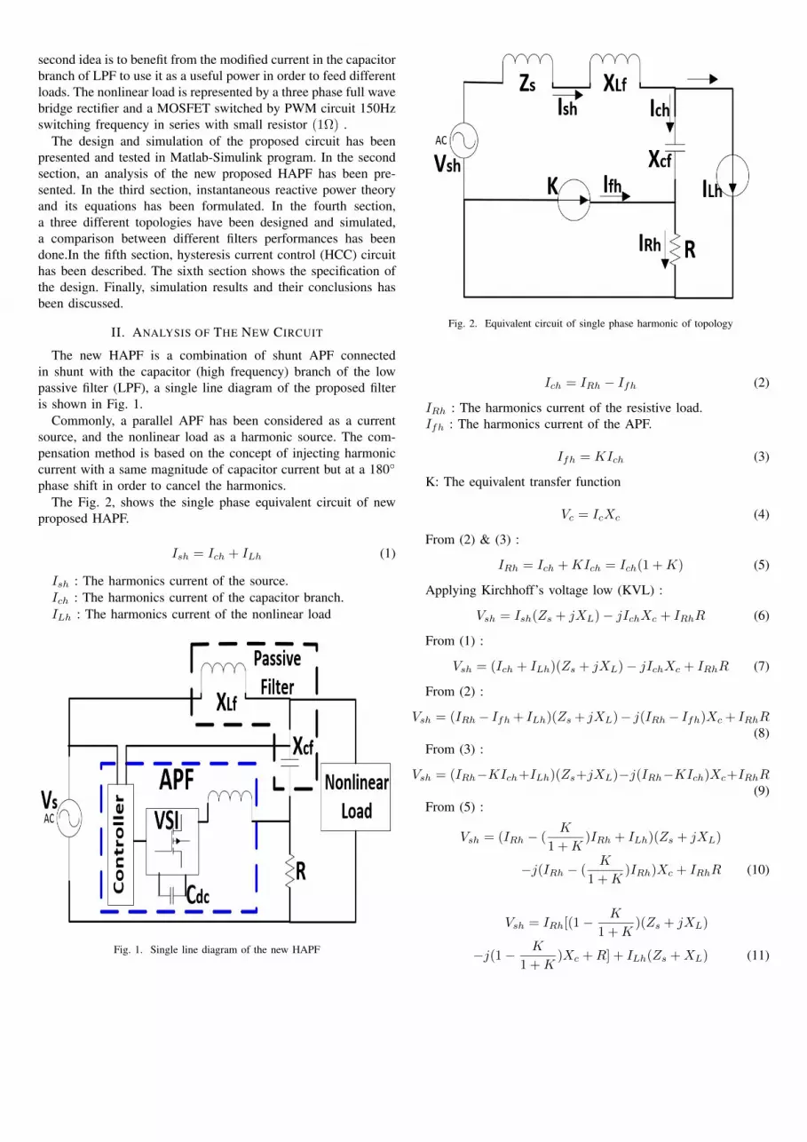
phase shift in order to cancel the harmonics.The Fig. 2, shows the single phase equivalent circuit of new
proposed HAPF.
Ish = Ich + ILh (1)
Ish : The harmonics current of the source.Ich : The harmonics current of the capacitor branch.ILh : The harmonics current of the nonlinear load
Fig. 1. Single line diagram of the new HAPF
Fig. 2. Equivalent circuit of single phase harmonic of topology
Ich = IRh − Ifh (2)
IRh : The harmonics current of the resistive load.Ifh : The harmonics current of the APF.
Ifh = KIch (3)
K: The equivalent transfer function
Vc = IcXc (4)
From (2) & (3) :
IRh = Ich +KIch = Ich(1 +K) (5)
Applying Kirchhoff’s voltage low (KVL) :
Vsh = Ish(Zs + jXL)− jIchXc + IRhR (6)
From (1) :
Vsh = (Ich + ILh)(Zs + jXL)− jIchXc + IRhR (7)
From (2) :
Vsh = (IRh− Ifh + ILh)(Zs + jXL)− j(IRh− Ifh)Xc + IRhR(8)
From (3) :
Vsh = (IRh−KIch+ILh)(Zs+jXL)−j(IRh−KIch)Xc+IRhR(9)
From (5) :
Vsh = (IRh − (K
1 +K)IRh + ILh)(Zs + jXL)
−j(IRh − (K
1 +K)IRh)Xc + IRhR (10)
Vsh = IRh[(1− K
1 +K)(Zs + jXL)
−j(1− K
1 +K)Xc +R] + ILh(Zs +XL) (11)

IRh =Vsh − ILh(Zs + jXL)
(1− K1+K )[Zs + jXL − jXc] +R
(12)
According to [7], the source impedance should present anegligible amount of impedance at the fundamental frequency(Zs = 0), then Zs does not cause any noticeable fundamentalvoltage drop. So that Zs ≈ 0 and Vsh ≈ 0, and when K=1 :
IRh =ILhXL
0.5(Xc −XL) + jR(13)
If XL << 1⇒ ∴ IRh ≈ 0 & Ish ≈ 0(waveform is sinusoidal)
III. INSTANTANEOUS REACTIVE POWER THEORY
The instantaneous reactive power (p-q) theory has been formu-lated by Akagi [13], it is based on the Clarke transformation [14]to convert voltages and currents in three-phase systems (abc) into(α, β , 0) orthogonal coordinates.
In three phase-three wire systems, splitting the zero-sequencecomponent from the abc components is the most distinctivefeature of applying (p-q) theory and that leads to simplificationof the equations [11].
The Clarke transformation, has the form:
[vαvβ
]=
√2
3
[1 −1
2−12
0√32−√3
2
]vavbvc
(14)
[iαiβ
]=
√2
3
[1 −1
2−12
0√32−√3
2
]iaibic
(15)
With the voltages and currents have transformed to the α andβ coordinates, the real and imaginary powers are given by:[
pq
]=
[vα vβvβ − vα
] [iaib
](16)
Where p is the real power and represents the total energyflow per time unity in the three-phase three-wire system, q isthe imaginary power and has a non-traditional physical meaningand gives the measure of the quantity of current or power thatflows in each phase without transporting energy at any instant[11].
p = vαiα + vβiβ = pav + pos (17)
pav and pos represent the average and oscillating parts of p.
The instantaneous imaginary (reactive) power (q) is given as:
q = −vαiβ + vβiα = qav + qos (18)
qav and qos represent the average and oscillating parts of q.
The instantaneous active current ip is defined in the α and βcoordinates as:
iαp =vα
v2α + v2βp (19)
iβp =vβ
v2α + v2βp (20)
The instantaneous reactive current,iq is defined in the α and βcoordinates as:
iαq = − vβv2α + v2β
q (21)
iβp =vα
v2α + v2βq (22)
Let the instantaneous powers in the α axis and the β axis bepα and pβ , respectively. They are given by the conventionaldefinition as follows:[
pαpβ
]=
[vα iαvβ iβ
]=
[vα iαpvβ iβp
]+
[vα iαqvβ iβq
](23)
The instantaneous real power in the three-phase circuit (p) isgiven as follows:
p = pα + pβ =v2α
v2α + v2βp+
v2βv2α + v2β
p+−vαvβv2α + v2β
q +vαvβv2α + v2β
q
(24)
iLα represents the reference current in the α coordinate isdefined as:
iLα = iαp + iαq (25)
iLβ represents the reference current in the β coordinate isdefined as:
iLβ = iβp + iβq (26)
iref represents the reference current in the abc coordinates iscalculated as:
irefairefbirefc
=
√2
3
1 0−12
√32
−12
−√3
2
[iLαiLβ]
(27)
IV. HYSTERESIS CURRENT CONTROL
HCC, is a technique of generating the required triggeringpulses by comparing the feedback signal with the referencecurrent and it is used for controlling the voltage source inverter.This method controls the switches of the voltage source inverterasynchronously to swing the current through the inductor up anddown, so that it follows the reference current. Hysteresis currentcontrol is the simplest control technique to apply in the timedomain [15]. Fig. 3, shows the hysteresis current control circuit.

Fig. 3. Hysteresis current controller
V. THE SYSTEM CONFIGURATION
The system configuration will be described in 3 steps:1) The first step represents an initial circuit consists of a three
phase voltage source (220 volt) with a nonlinear load (threephase full wave bridge rectifier in series with a 150Hzpulsating MOSFET switch and (1 Ω) resistor, as shownin Fig. 4.
2) The second circuit consists of a nonlinear load and aLow pass filter with resonance frequency f = 50 Hz,L = 1.35mH , C = 7.5mF,Zfilter = 0.42Ω.The role of the LPF is to eliminate the harmonics from thesource by forcing the harmonics current to pass through the(high frequency) C-branch. The circuit is shown below inFig. 5.The effects of harmonics on the current is obvious in Fig. 6,which shows the current waveform in the capacitor branchbefore adding APF.
3) The final circuit which represents the new proposed circuithas been produced by adding a three phase shunt APF afterthe capacitor in order to compensate the harmonics current(which is eliminated by using LPF) in the C-branch andin the source current, and also to compensate the reactivepower of the system. The circuit is shown below in Fig. 7.
Fig. 4. Initial circuit
Fig. 5. Circuit with low pass filter
Fig. 6. C-branch’s current before adding APF
The shunt APF has been designed and tested accordingto [11] by using the instantaneous reactive power theory,Clarke transformation and HCC method which is mostlypreferred in APF control schemes to control inverter’spulses. Fig. 8, shows the design of the APF and Fig. 9,shows APF’s control circuit.
Fig. 7. New proposed HAPF

Fig. 8. Shunt active power filter design
Fig. 9. APF control circuit

VI. SPECIFICATION OF THE DESIGN
The APF’s control steps has been illustrated in Fig. 10. Thesimulation of the proposed circuit is performed on a three phasebalanced non-linear load as shown below.
1) System parameters :
TABLE ISYSTEM PARAMETERS
VSource 220 AC VoltSystem Frequency 50 Hz
Load Resistor 1 ΩMOSFET Switching Frequency 150 Hz
2) Low pass filter parameters:
TABLE IILPF PARAMETERS
Inductor 1.35 mHCapacitor 7.5 mF
3) Active power filter parameters:
TABLE IIIAPF PARAMETERS
Inductor 0.5 mHDC link capacitor 2.2 FDc link voltage 200 VDC
Line resistor 0.1 Ω
Fig. 10. APF control steps
VII. SIMULATION RESULTS
All the three circuits have been modeled and simulated suc-cessfully in Matlab-Simulink program. The table (IV) belowsummarized the results of the simulation with a comparisonbetween the values of Total Harmonic Distortion (THD%) of threeaforementioned circuits.
In the first circuit (without filter) THD percentage value was73.9% (because of the performance of the MOSFET). In thesecond circuit, LPF has reduced the value of THD-Source in thesecond circuit (with LPF) to 6.4% which proves the effectivenessof the LPF, but the THD of the C branch became more than49.5% which is normal because of the high order frequenciespass through capacitor. In the third case (proposed HAPF), thevalue of THD-Source has reflected the excellent performance ofthe new proposed HAPF which reduced THD-Source to 1.9%and the value of THD-C has reduced to 9.7% and the value ofTHD-R which represents the harmonics value of the sample load(1 Ω), has reduced to 8.1%.
Fig. 11, shows the source current before using filtering process.Fig. 12, shows the source current after using the proposed HAPF.Fig. 13, shows the waveform of IR after filtering, small spikeshave been shown on the waveform representing the effects ofharmonics which were reduced in comparing with the waveformshown previously in Fig. 6, which shows the filter currentwaveform before adding the shunt APF.
It can be easily concluded, from the results and waveforms thatthe (THD%) value in the source and in the LPF branches, hasdecreased hugely especially in the resistor branch (from 49.5% to8.1%) and that’s prove the ability to utilize the harmonics powerand the ability of using the modified current as a power supplyto feed some loads.
TABLE IVTHD VALUES
Without Filter With LPF HAPFTHD-Source 73.9% 6.4% 1.9%
THD-C — 49.5% 9.4%THD-R — — 8.1%
Fig. 11. Source current before filtering

Fig. 12. Source current after filtering
Fig. 13. The current of resistive load after filtering
VIII. CONCLUSION
This paper has presents a new topology of three phase HAPF.The system has been designed, tested and simulated by Matlab-Simulink program in three steps; firstly, without using filters,secondly, with LC low pass filter, finally, using LPF in combinewith APF which represent HAPF. After a comparison betweenthe values of total harmonic distortion (THD%) in three afore-mentioned circuits, the results of the simulation confirmed theeffectiveness of the proposed HAPF because of the big decreasingin the THD value and high rate elimination of the harmonics.The proposed HAPF offers a reactive power compensation forthe circuit because of using shunt APF. Consequently, the powerquality of the circuit will improve.
This paper has submit a new idea to benefit of eliminatedharmonic current in the C-branch of LPF through using APFin shunt with C-branch of LPF and compensate high frequencycurrents in order to use it as a power supply to feed differentloads.
In this research, a resistive load has been presented as aninvested load. However, in practical life lighting bulbs can beused as loads.
ACKNOWLEDGMENT
The first author gratefully acknowledge the big support of theHigher Committee for Education Development (HCED) in Iraq.
REFERENCES
[1] C. Francisco, Harmonics and power systems. CRC press, 2006.[2] B. Singh, B. N. Singh, A. Chandra, K. Al-Haddad, A. Pandey, and D. P.
Kothari, “A review of three-phase improved power quality ac-dc converters,”Industrial Electronics, IEEE Transactions on, vol. 51, no. 3, pp. 641–660,2004.
[3] L. Gyugyi and E. C. Strycula, “Active ac power filters,” in Proc. IEEE/IASAnnu. Meeting, vol. 19, 1976, pp. 529–535.
[4] L. Czarnecki, “An overview of methods of harmonic suppression in distribu-tion systems,” in Power Engineering Society Summer Meeting, 2000. IEEE,vol. 2, 2000, pp. 800–805.
[5] A. Nassif, W. Xu, and W. Freitas, “An investigation on the selectionof filter topologies for passive filter applications,” Power Delivery, IEEETransactions on, vol. 24, no. 3, pp. 1710–1718, July 2009.
[6] T. Sekar and B. Rabi, “A review and study of harmonic mitigationtechniques,” in Emerging Trends in Electrical Engineering and EnergyManagement (ICETEEEM), 2012 International Conference on, Dec 2012,pp. 93–97.
[7] L. Chen, Y. Xie, and Z. Zhang, “Comparison of hybrid active powerfilter topologies and principles,” in Electrical Machines and Systems, 2008.ICEMS 2008. International Conference on. IEEE, 2008, pp. 2030–2035.
[8] F. Z. Peng, H. Akagi, and A. Nabae, “A new approach to harmoniccompensation in power systems-a combined system of shunt passive andseries active filters,” Industry Applications, IEEE Transactions on, vol. 26,no. 6, pp. 983–990, 1990.
[9] F. Z. Peng, “Application issues of active power filters,” Industry ApplicationsMagazine, IEEE, vol. 4, no. 5, pp. 21–30, 1998.
[10] J.-C. Wu, H.-L. Jou, Y.-T. Feng, W.-P. Hsu, M.-S. Huang, and W.-J. Hou,“Novel circuit topology for three-phase active power filter,” Power Delivery,IEEE Transactions on, vol. 22, no. 1, pp. 444–449, 2007.
[11] H. Akagi, E. H. Watanabe, and M. Aredes, Instantaneous power theory andapplications to power conditioning. John Wiley & Sons, 2007, vol. 31.
[12] H. Al-bayaty, M. Ambroze, and M. Z. Ahmed, “Taking advantage of theharmonics at the load side using passive filters,” in Systems and Informatics(ICSAI), 2014 2nd International Conference on, Nov 2014, pp. 169–174.
[13] H. Akagi, Y. Kanazawa, K. Fujita, and A. Nabae, “Generalized theory ofinstantaneous reactive power and its application,” Electrical engineering inJapan, vol. 103, no. 4, pp. 58–66, 1983.
[14] E. Clarke, Circuit Analysis of AC Power Systems. J. Wiley & sons,Incorporated, 1950, vol. 2.
[15] J. Zeng, L. Jiao, Y. Ni, S. Chen, B. Zhang, C. Shen, and F. Wu, “A novelhysteresis current controller for active power filter with constant switchingfrequency,” in Power Electronics and Motion Control Conference, 2000.Proceedings. IPEMC 2000. The Third International, vol. 2, 2000, pp. 692–697 vol.2.


