Embed Size (px)
Citation preview
19 Thermal Testing
J. W. Welch*
Introduction To ensure successful vehicle and payload operation, space programs subject hard- ware to extensive ground testing. Thermal tests demonstrate the performance and operation of units, subsystems, payloads, and entire space vehicles in thermal environments that are, at minimum, realistic simulations of flight conditions. At the unit level, these tests include thermal cycling and thermal vacuum tests. At the space vehicle level, they include thermal cycling, thermal vacuum, and thermal balance tests. This chapter provides the objectives of each thermal test and describes the test parameters and procedures used to meet those objectives.
Over the past decades, a series of documents has specified and described mili- tary requirements for spacecraft thermal testing. The first, MIL-STD-1540A, was written in 1974 for Department of Defense space programs to standardize test requirements and establish a uniform set of definitions, environmental criteria, and test methods for military space vehicles, subsystems, and units. It introduced a common language defining test categories, levels, and sequences.
Published in 1982, MIL-STD-1540B was an update to MIL-STD-1540A and was oriented toward low-risk, long-life space vehicles. This document expanded testing provisions in that it disallowed flying qualification hardware, introduced the protoflight concept, reduced testing requirements for one-time or low-volume programs, separated the roles of workmanship verification and design demonstra- tion, emphasized performance testing, and increased the role of thermal cycling. Three years later, MIL-HDBK-340 was published as an application guideline for MIL-STD-1540, providing much-needed explanations, guidance, and rationale to the users of MIL-STD- 1540B.
MIL-STD- 1540C, published in 1993, introduced test parameter flexibility and included test requirements for boosters and launch vehicles. It considered cost- and failure-effectiveness knowledge based upon statistical data and realigned defi- nitions into a more standard terminology. To introduce industry practices related to the rapid expansion of commercial programs, MIL-STD-1540D was published in 1999. While it retained MIL-STD-1540C requirements as an attachment in MIL-HDBK-340A, MIL-STD-1540D was process oriented, providing "what to" and not "how to" guidelines. It aligned expected methodologies and acceptance testing requirements without specifically directing test practices and procedures.
The consequences of acquisition reform dramatically changed the process with which space hardware requirements are verified. In line with commercial prac- tices, risk became a managed parameter, weighed against program cost and sched- ule. The industry response to MIL-STD-1540D has been mixed. Several compa- nies whose prime customer remains the Air Force have developed internal
*The Aerospace Corporation, E1 Segundo, California.
709
710 Thermal Testing
environmental test documents based upon previous experiences with MIL-STD- 1540 test requirements. Companies whose principal products are commercial spacecraft have adopted test practices that reflect commercial practices. These requirements tend to emphasize reduced cost and schedule testing with higher risk acceptance. Still other companies have proposed tailored versions of MIL-STD-1540C.
The reality of acquisition reform in the context of thermal testing is that non- commercial test requirements are moving toward equivalent commercial prac- tices. For commercial spacecraft whose programs represent more than just a few vehicles, a higher level of risk may be acceptable. Military customers, however, are less willing to accept the level of risk associated with commercial vehicles, so the process of applying commercial practices to military programs is still in its infant stage. A primary observation is that without standard test requirements, such as those provided by MIL-STD-1540, the effectiveness of testing is a subject of debate. Acquisition reform should have resulted in "smarter testing"; instead the prevailing attitude favors test deletion. 191
References to thermal test parameters in this chapter are keyed to requirements given in MIL-STD-1540B or MIL-STD-1540C. Present trends and current prac- tices as they compare to MIL-STD-1540 recommendations are also discussed. Brief summaries of commercial and NASA space program thermal test practices are also provided.
Definitions The following definitions have contributed to the establishment of a common ter- minology within the thermal testing community.
Item Levels
Unit
A unit is a functional item that is viewed as a complete and separate entity for pur- poses of manufacturing, maintenance, or record keeping. Examples include indi- vidual electronics box, battery, thruster, and electrical harness.
Subsystem
A subsystem is an assembly of functionally related units. It consists of two or more units and may include interconnection items, such as cables or tubing, and the supporting structure to which the units are mounted. Examples include electric power, attitude control, telemetry, thermal control, and propulsion subsystems.
Launch Vehicle
A launch vehicle is one or more of the lower stages of a flight vehicle capable of launching upper-stage vehicles and space vehicles, usually into a suborbital trajec- tory. A fairing to protect the space vehicle, and possibly the upper-stage vehicle, is typically considered to be part of the launch vehicle.
Definitions 711
Upper-Stage Vehicle
An upper-stage vehicle is one or more stages of a flight vehicle capable of inject- ing a space vehicle or vehicles into orbit from a suborbital trajectory that resulted from operation of a launch vehicle.
Space Vehicle
A space vehicle is an integrated set of subsystems and units capable of supporting an operational role in space. A space vehicle may be an orbiting vehicle, a major portion of an orbiting vehicle, or a payload that performs its mission while attached to a launch or upper-stage vehicle. The space vehicle includes the pay- loads that constitute its mission.
Test Categories Development Tests
Development tests, also known as engineering tests, are conducted to accomplish a number of objectives, including the validation of new design concepts and the reduction of risk in committing designs to hardware fabrication. A full list of development test objectives will be given in a subsequent section.
Requirements for a development test depend upon its objective, the maturity of the subsystem and units, and the operational requirements of the specific program or hardware. Development test requirements are necessarily unique to test objec- tives and are not specified in military or commercial standards. Development tests may be conducted on breadboard equipment, prototype hardware, or engineering models.
Qualification Tests
Formal qualification tests are conducted to demonstrate that the design, manufac- turing process, and acceptance program produce mission items that meet specifi- cation requirements. Qualification tests also validate the planned acceptance program, including test techniques, procedures, equipment, instrumentation, and software.
Each type of flight item that is to be acceptance tested undergoes a correspond- ing qualification test, with the exception of some structural items. The test item is produced from the same drawings that are used for production of the flight hard- ware. Its production uses the same materials, tooling, manufacturing processes, and level of personnel competency as are used for production of the flight hardware.
To demonstrate design, the qualification environment exposes the qualification hardware to conditions more severe than expected during the operational life of the flight hardware. It considers not only the most extreme flight environments, but also the maximum number of cycles that can be accumulated in acceptance testing and retesting. Because of the severity of this environment, qualification hardware is not flown.
Acceptance Tests
Formal acceptance tests demonstrate the acceptability of a deliverable item. They verify conformance to specification requirements and provide quality-control
712 Thermal Testing
assurance against workmanship and material deficiencies. Acceptance tests act as an environmental stress screen to precipitate incipient failures resulting from latent defects in parts, materials, and workmanship. These tests, which are con- ducted after qualification testing, prove the flightworthiness of the article.
Alternative Test Strategies
Hardware items subjected to qualification tests are themselves not eligible for flight, because remaining life from the viewpoint of fatigue and wear has not been demonstrated. Yet programmatic realities of limited production, fight schedules, and budgetary constraints do not always provide for dedicated nonflight qualifica- tion items. In response, strategies have evolved to minimize the risk created by this situation. The concepts of spares, flightproofing, and protoqualification pro- vide alternative test strategies for flight items that do not follow the qualification acceptance test sequence. These strategies, or a combination thereof, may be used at the vehicle, subsystem, and unit levels. They introduce a higher risk to the pro- gram than the standard acceptance test that follows qualification and design verifi- cation. The higher risk is sometimes mitigated by enhanced development testing and by increased design factors of safety.
Spares In the spares concept, a qualification vehicle is refurbished with acceptance tested units. Qualification units are removed from the qualification vehicle, and the vehi- cle is refurbished as necessary. Usually a new set of critical units is installed that has only been acceptance tested. The vehicle is qualified for flight when it com- pletes vehicle acceptance testing.
Flightproofing With a flightproof strategy, all flight items are subjected to enhanced acceptance testing, and there is no qualification item. The risk is that reduced test margins allow possible design deficiencies to remain undetected, and formal demonstra- tion of remaining life for the flight item does not exist. The risk is partially allevi- ated by acceptance testing the flight item to environmental stresses greater than those specified for acceptance tests (but less than qualification requirements).
Protoqualification With a protoqualification strategy (also termed protoflight qualification, protof- light, or protoqual), a modified qualification (protoqualification) is conducted on a single item, and that test item is considered available for flight. The normal accep- tance tests are then conducted on all other items. The primary difference between protoqualification and flightproof strategies centers on the number of items tested in the enhanced acceptance environment. Under flightproofing, all flight items are subjected to the enhanced acceptance environment, whereas under protoqualifica- tion, only one of a group of identical items is subjected to the enhanced accep- tance environment.
Definitions 713
Thermal Test Objectives
Environmental Stress Screening
Environmental stress screening is the process that subjects hardware to physical stresses and forces flaws that are not ordinarily apparent into observable failures. These flaws are latent defects that could cause premature component failure. The environment associated with environmental stress screening is more severe than the one expected in actual usage. In thermal testing, the test temperature, the num- ber of test cycles, and the rate of temperature change are parameters that establish the efficiency of environmental stress screening.
Turn-On Capability
Turn-on capability demonstrates that a unit can be activated within a severe envi- ronment. For thermal verification, turn-on might be shown at hot and cold temper- atures, in a rapidly changing temperature environment, or under severe thermal gradients.
Survival Demonstration
Survival temperatures represent the range over which a unit is expected to survive. The unit must demonstrate that it can be turned on at these temperatures, and although performance does not need to meet specification at these extreme tem- peratures, the unit must not show any performance degradation when the environ- ment or unit temperature is returned to the unit's operational temperature range. The survival range is the most severe temperature range specification for a unit. Survival temperatures are sometimes given as operational survival and nonopera- tional survival. The cold turn-on temperature is often identical to, or nearly the same as, the cold survival temperature.
Thermal Tests
Thermal Cycle Tests
Thermal cycling subjects the test article to a number of cycles of hot and cold tem- perature plateaus in an ambient air or gaseous nitrogen environment. Convective heat transfer is enhanced such that the cycling can be relatively rapid. Cycling serves primarily as an environmental stress screen by revealing latent workman- ship or material defects. Performance verification is a secondary objective accom- plished through functional tests performed at hot and cold temperature plateaus.
Thermal Vacuum Tests
Thermal vacuum tests subject the test article to a number of cycles of hot and cold temperatures in a vacuum environment. Because it is conducted without convec- tive heat transfer, this test is the most realistic ground simulation of the flight envi- ronment. Therefore its primary purpose is performance verification through functional testing. Temperature transition is slower than in the thermal cycling test, so stress screening is of secondary importance.
Thermal Balance Tests
Thermal balance tests, usually performed as part of subsystem or space vehicle thermal vacuum testing, have two purposes: verification of the thermal control
714 Thermal Testing
subsystem and correlation of thermal analytic models. Dedicated test phases that simulate flight conditions are used to gather steady-state temperature data that are compared to model predictions. Test phases also simulate cold and hot conditions to verify all aspects of the thermal hardware and software, including heater opera- tion, radiator sizing, and critical heat transfer paths.
Burn-In Tests
Burn-in tests are typically part of unit thermal cycle tests in which additional test time is accrued to meet a set requirement. The unit is either cycled or held at an elevated hot temperature during the burn-in test, and the unit is operational, although functional tests are not performed.
Thermal Margins Thermal Uncertainty Margin
The thermal uncertainty margin is a margin of safety applied to worst-case ana- lyric temperature predictions (from all mission phases) to account for uncertain- ties inherent in parameters such as complex view factors, surface properties, radiation environment, joint and interface conduction, and ground simulation. For passive thermal control, the thermal uncertainty margin is a temperature added to worst-case temperature predictions. For active thermal control, the thermal uncer- tainty margin is a power margin to increase control authority. When the margin is added to worst-case temperature predictions, the resulting temperature forms the basis for the acceptance temperature range.
Protoqualification Thermal Margin
The protoqualification margin is the temperature margin added to acceptance tem- peratures for protoqualification testing. The margin is intended to increase the severity of the acceptance test environment, but not to the same extent that the qualification environment stresses the test hardware.
Qualification Thermal Margin
The qualification margin is the increase in an environmental condition over that expected during service life, including acceptance testing, to demonstrate that adequate ruggedness exists in the design and in its implementation. A margin may include an increase in level or range, or an increase in duration or cycles of expo- sure, as well as any other appropriate increase in severity. It is used to prove the design of the test hardware by exposing design defects, to demonstrate robustness, to show tolerance to degradation (fatigue and wear), and to prove test condition tolerances.
Additional Terminology
Temperature Stabilization
Temperature stabilization is a criterion that establishes the point at which the test hardware has reached a stable, or nearly steady, thermal equilibrium with the test environment and is within the test tolerance of the prescribed test temperature. For both thermal cycle and thermal vacuum testing, temperature stabilization for a unit is achieved when the unit baseplate is within the allowed test tolerance on the
Design Environments 715
specified test temperature, and the rate of temperature change has been less than 3°C per hour for 30 minutes. For steady-state thermal balance testing, temperature stabilization is achieved when the unit with the largest thermal time constant is within 3°C of its steady-state value, as determined by numerical extrapolation of test temperatures, and the rate of change is less than I°C per hour.
Thermal Dwell
Thermal dwell of a unit at hot or cold extremes is the time required to ensure that internal parts and equipment have achieved thermal equilibrium or the test tem- perature. Thermal dwell begins at the onset of thermal stabilization and is fol- lowed by functional or performance testing of the unit.
Thermal Soak
The thermal soak duration of a unit at the hot or cold extreme of a thermal cycle is the time that the unit is operating and its baseplate is continuously maintained within the allowable tolerance of the specified test temperature.
Thermal Test Tolerance
The thermal test tolerance is the temperature tolerance accepted for thermal test parameters and conditions. Unless otherwise stated, thermal test parameters should be assumed to include the maximum allowable test tolerance of ___3°C over an applicable temperature range o f - 5 4 to +100°C. For conditions outside this range, the tolerance should be appropriate for the purpose of the test.
Design Environments
Thermal Environments A thermal design environment includes the heat flowing into and out of a system, be that system a unit, a radiator surface, or a complete space vehicle. External heating from the sun, Earth, and other planets combines with internal heat genera- tion to form the input to an energy balance. Radiation, conduction, and convection are modes of heat transfer that are used to assess heat flow throughout and across the boundaries of the system. These phenomena result in a representation of the thermal behavior of the system that allows heat flow and temperatures to be pre- dicted for different environmental conditions.
In the design process, considerable time is spent analyzing realistic thermal environments to determine which conditions will be the most stressing. The selec- tion of the worst-case environment considers all possible combinations of worst- case conditions that could occur during each operation mode. Factors include time of year, sun-orbit orientation, eclipse duration, operational mode, time of mission (beginning- or end-of-life), and surface degradation. These worst-case conditions are used to predict, using thermal analytic models, the hottest and coldest temper- atures the unit or system may experience in its mission life. These values are com- puted unit by unit, as a worst-case combination of conditions for one unit may not prove to be worst case for another. The hottest and coldest temperatures establish a range called the nominal extreme temperature range (or analytic extreme tem- perature range), which is the basis for all test temperatures.
716 Thermal Testing
Process of Establishing Test Temperatures
The process of determining test temperatures will be described as applicable for military programs, and variations to this process will follow.
Unit Level Test Temperatures
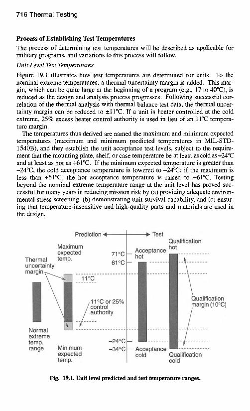
Figure 19.1 illustrates how test temperatures are determined for units. To the nominal extreme temperatures, a thermal uncertainty margin is added. This mar- gin, which can be quite large at the beginning of a program (e.g., 17 to 40°C), is reduced as the design and analysis process progresses. Following successful cor- relation of the thermal analysis with thermal balance test data, the thermal uncer- tainty margin can be reduced to _+11°C. If a unit is heater controlled at the cold extreme, 25% excess heater control authority is used in lieu of an 11°C tempera- ture margin.
The temperatures thus derived are named the maximum and minimum expected temperatures (maximum and minimum predicted temperatures in MIL-STD- 1540B), and they establish the unit acceptance test levels, subject to the require- ment that the mounting plate, shelf, or case temperature be at least as cold as-24°C and at least as hot as +6 I°C. If the minimum expected temperature is greater than -24°C, the cold acceptance temperature is lowered to -24°C; if the maximum is less than +61°C, the hot acceptance temperature is raised to +61°C. Testing beyond the nominal extreme temperature range at the unit level has proved suc- cessful for many years in reducing mission risk by (a) providing adequate environ- mental stress screening, (b) demonstrating unit survival capability, and (c) ensur- ing that temperature-insensitive and high-quality parts and materials are used in the design.
Prediction -" -,q
Maximum expected 71 °C
Thermal uncertainty temp. 61oc margin
ii oc . . . . .
.11 °C or 25% / control _,authority
Normal extreme temp. -24°C range
• " Test Qualification hot
-- hAoCtCeptance I I . . . . . . . .
iiiiiii ii iiiiiii
I Minimum -34°C I-- Acceptance expected [ cold Qualification temp. cold
Fig. 19.1. Unit level predicted and test temperature ranges.
Design Environments 717
Unit qualification tests are conducted at temperatures 10°C colder (even if heat- ers are used for thermal control) and 10°C hotter than the acceptance test tempera- tures, subject to the constraint that the mounting plate or shelf be at least as cold as -34°C and at least as hot as +7 l°C.
With a protoqualification approach, a modified qualification test is performed on a single item, and that test item is then available for flight. The primary objective of qualification testing (verifying the design of the test article) is combined with the primary objective of acceptance testing (verifying the article's workmanship and flightworthiness) in this single test. Because this strategy eliminates the redundancy of building qualification hardware, it enables significant cost savings. At the unit level, protoqualification thermal testing is performed with the same test parameters as qualification testing, except the hot and cold temperatures are 5°C beyond the acceptance temperatures.
Certain temperature-sensitive units are sometimes exempt from the design mar- gins described. Candidates for margin waiver are units that exhibit extremely tight operating temperature ranges (e.g., batteries, propellant valves, extremely accurate clocks, and some inertial reference units). Batteries are usually tightly controlled toward cold temperatures to increase life. Representative range values for NiCd batteries are: operating, 0 to +25°C; survival/turn-on,-10 to +40°C.
System Level Test Temperatures
At the system level, test temperature extremes are established for individual zones of the space vehicle. The zones represent logical groupings of similar equipment types and similar temperature ranges. Each is managed independently to achieve different temperature ranges. In each zone, as many units as are practical (but at least one) are driven to the zone's hot and cold temperature extremes, which include the appropriate thermal margins (acceptance or qualification). Care must be exercised and sufficient instrumentation installed to assure that no unit is exposed to temperature conditions beyond its unit test temperature.
System level temperature margins are the same as those used for unit level test- ing: the thermal uncertainty margin is 11°C, and the qualification margin is 10°C. Implementation of the thermal margin at the system level, however, depends upon the thermal test. Thermal vacuum testing applies both margins in a manner similar to unit level testing. Thermal cycle testing, on the other hand, specifies a total tem- perature range over which the satellite is tested. For acceptance testing, the mini- mum vehicle temperature range is 50°C; for qualification testing, 70°C.
Protoqualification testing at the system level is similar to protoqualification test- ing at the unit level. The thermal vacuum test has a 5°C margin beyond the accep- tance temperature, and the thermal cycle test is performed over a 60°C range.
In practice, the approach described in establishing test temperatures is generally implemented as presented. The greatest deviation arises from using the standard acceptance temperature range of-24°C to +6 I°C for unit thermal testing. As in the case of batteries, some units have restricted thermal operation, such that these temperature ranges are not practical. In other cases, reliability concerns with oper- ating equipment at elevated temperatures result in thermal designs that are biased in temperature to a worst-case hot value significantly colder than +6 l°C. Payload equipment is one such example where operational performance is sometimes not
718 Thermal Testing
possible at elevated hot temperatures. As a general rule, however, electronic equipment should be tested to as wide a temperature range as possible at the unit level to enhance the effectiveness of environmental stress screening.
Thermal Uncertainty Margin As previously stated, the thermal uncertainty margin is a margin of safety used to account for uncertainties such as complex view factors, surface properties, radia- tion environment, joint and interface conduction, and ground simulation. The mar- gin recognizes that many assumptions are used in the development of thermal analytic models that calculate temperature predictions. These assumptions have inherent uncertainties that can result in temperatures significantly different than those predicted with analytic thermal models. Units mounted internally are mod- eled with uncertainties associated with power dissipation, interface conduction, material conductivity, and boundary conditions. Units mounted externally typi- cally have much higher uncertainties in thermal design parameters, such as view factors, environmental heating, and surface properties, as well as the uncertainties listed for internally mounted units. As a result, externally mounted equipment commonly carries thermal uncertainty margins greater than the minimum value.
Thermal uncertainty associated with temperature predictions is reduced during the design-analysis-test process as the hardware design becomes firm, as improved and more detailed analyses are conducted, and as development tests are completed. The thermal balance test substantially reduces temperature-prediction uncertainty. Deviation between on-orbit temperature measurements and preflight temperature predictions is a measure of the final uncertainty between the analytic and test processes.
The _1 I°C thermal uncertainty margin is the result of extensive comparisons between preflight predictions and flight temperature measurements. In a report by Stark 192 that summarized much of the work, a study of 20 critical spacecraft units showed that the thermal balance test and subsequent model correlation reduced the standard deviation between prediction and on-orbit measurement from 9 to 5.5°C. As the intent of MIL-STD-1540 is to have a 95% (2-~) confidence that design temperatures (maximum and minimum expected temperatures) are never exceeded in flight, the military practice is to use the 11°C thermal uncertainty mar- gin for predictions verified by thermal balance test results and margins greater than this for unverified analytic predictions. Some have further proposed that the minimum thermal uncertainty margin be 17°C prior to the thermal balance test. As result of this work and the significant data accumulated since this report, the _ l l °C uncertainty margin has been shown necessary to assure high confidence that flight temperatures will not exceed minimum and maximum expected unit temperatures.
Passive and Active Thermal Control Methods
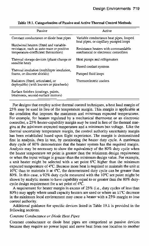
The thermal uncertainty margin varies depending on whether passive or active thermal control techniques are used. The _ 11°C margin is used for hardware con- trolled by passive methods and a 25% control authority margin is used for hard- ware controlled by active methods. Table 19.1 categorizes thermal control methods as active or passive and can be used for selecting the appropriate thermal uncertainty margin.
Design Environments 719
Table 19.1. Categorization of Passive and Active Thermal Control Methods
Passive Active
Constant conductance or diode heat pipes
Hardwired heaters (fixed and variable- resistance, such as auto-trace or positive temperature-coefficient thermistors)
Thermal storage devices (phase change or sensible heat)
Thermal insulation (multilayer insulation, foams, or discrete shields)
Radiators (fixed, articulated, or deployable) (with louvers or pinwheels)
Surface finishes (coatings, paints, treatments, second-surface mirrors)
Variable conductance heat pipes, looped heat pipes, or capillary pumped loops
Resistance heaters with commandable mechanical or electronic controllers
Heat pumps and refrigerators
Stored coolant systems
Pumped fluid loops
Thermoelectric coolers
For designs that employ active thermal control techniques, a heat load margin of 25% may be used in lieu of the temperature margin. This margin is applicable at the condition that imposes the maximum and minimum expected temperatures. For example, for heaters regulated by a mechanical thermostat or an electronic controller, a 25 % heater-capability margin may be used in lieu of the thermal mar- gins at the minimum expected temperature and a minimum bus voltage. Like the thermal uncertainty temperature margin, the control authority uncertainty margin has been established based upon flight experience. The margin is demonstrated first in analysis, then in test, by monitoring the heater duty cycle. A maximum duty cycle of 80% demonstrates that the heater system has the required margin. Analysis may be necessary to show the equivalency of the 80% duty cycle when the heater temperature set point is greater than the minimum design requirement or when the input voltage is greater than the minimum design value. For example, a unit heater might be selected with a set point 6°C higher than the minimum expected temperature of 4°C. Because more heat is required to maintain the unit at 10°C than to maintain it at 4°C, the demonstrated duty cycle can be greater than 80%. In this case, a 92% duty cycle measured with the 10°C set point might be shown by analytic means to have capability equal to or greater than the 80% duty- cycle design requirement for a set point of 4°C.
A requirement for heater margin in excess of 25% (i.e., duty cycles of less than 80%) may apply where small capacity heaters are used or where an 11°C decrease in the minimum local environment may cause a heater with a 25% margin to lose control authority.
Additional guidance for specific devices listed in Table 19.1 is provided in the following sections.
Constant Conductance or Diode Heat Pipes
Constant conductance or diode heat pipes are categorized as passive devices because they require no power input and move heat from one location to another
720 Thermal Testing
with a minimal temperature difference. Thermal performance testing, which is conducted at the highest assembly level practical (subsystem or space vehicle level), should demonstrate the _+11°C margin and should also, if possible, provide data to show each heat pipe is functional at the system level acceptance test. The design is verified by demonstrating at the unit level the heat transport capability with at least 125% of that required for the nominal predicted heat under the tem- perature conditions providing the smallest capacity margin. The nominal heat load is defined as that predicted by the analytical model in its worst-case condition.
Variable Conductance Heat Pipes
Variable conductance heat pipes using noncondensable gas reservoirs for temper- ature control are categorized as active devices in Table 19.1. Although they work very similarly to constant conductance heat pipes, which are categorized as pas- sive devices, variable conductance heat pipes almost always utilize heaters or another provision to control the gas-front radiator area. Thermal performance test- ing, which is also conducted at the highest assembly level practical, should dem- onstrate an acceptable heat rejection margin, variable conductance range, and heat pipe turnoff. The ability of the entire heat pipe system, not just the heat pipe, to reject heat should be verified. Therefore, the test must be performed at a high enough level to demonstrate performance parameters (with margin) that include the radiator area and environment. The heat rejection margin is shown when 125% of the nominal predicted heat load is applied to the evaporator mounting plate, under the worst-case hot simulated conditions, and the plate temperature is equal to or less than the maximum expected temperature. The variable conductance range is shown when 110% of the nominal predicted heat load is applied to the evaporator mounting plate, under the worst-case hot simulated environmental con- ditions, and the heat pipe still possesses variable conductance, as proven by the location of the gas or working fluid-vapor interface within the condenser portion of the pipe. Heat pipe turnoff requirements depend upon the type of reservoir in the system. For a heat pipe reservoir with active temperature control, the heat pipe is turned off, i.e., decoupled from the condenser by virtue of the gas (vapor) loca- tion, when the evaporator mounting plate temperature is at least 6°C or higher than the minimum expected temperature. For a heat pipe with a passively controlled reservoir, the turnoff points should be at least 11°C higher than the minimum expected temperature.
At the unit level, the heat pipe transport capability should be the same as defined for constant conductance heat pipes, at least 125% of that required for the nominal predicted heat load at the maximum expected temperature of the evaporator. The reservoir and evaporator temperatures may be adjusted as required to facilitate the simplest test procedure with the ambient environment available.
Heaters
Hardwired heaters or heaters using fixed or variable resistance elements that dem- onstrate a large variation in resistance with temperature are to be treated as passive devices. Resistance heaters with mechanical controllers (such as bimetallic ther- mostats), or commandable or electronic (solid-state) controllers, are active devices.
Design Environments 721
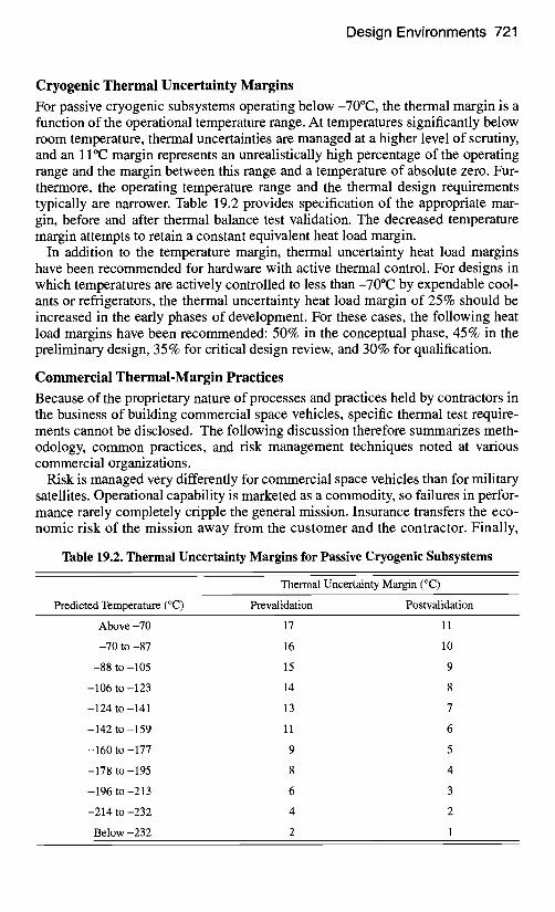
Cryogenic Thermal Uncertainty Margins For passive cryogenic subsystems operating below -70°C, the thermal margin is a function of the operational temperature range. At temperatures significantly below room temperature, thermal uncertainties are managed at a higher level of scrutiny, and an 1 I°C margin represents an unrealistically high percentage of the operating range and the margin between this range and a temperature of absolute zero. Fur- thermore, the operating temperature range and the thermal design requirements typically are narrower. Table 19.2 provides specification of the appropriate mar- gin, before and after thermal balance test validation. The decreased temperature margin attempts to retain a constant equivalent heat load margin.
In addition to the temperature margin, thermal uncertainty heat load margins have been recommended for hardware with active thermal control. For designs in which temperatures are actively controlled to less than-70°C by expendable cool- ants or refrigerators, the thermal uncertainty heat load margin of 25% should be increased in the early phases of development. For these cases, the following heat load margins have been recommended: 50% in the conceptual phase, 45% in the preliminary design, 35% for critical design review, and 30% for qualification.
Commercial Thermal-Margin Practices Because of the proprietary nature of processes and practices held by contractors in the business of building commercial space vehicles, specific thermal test require- ments cannot be disclosed. The following discussion therefore summarizes meth- odology, common practices, and risk management techniques noted at various commercial organizations.
Risk is managed very differently for commercial space vehicles than for military satellites. Operational capability is marketed as a commodity, so failures in perfor- mance rarely completely cripple the general mission. Insurance transfers the eco- nomic risk of the mission away from the customer and the contractor. Finally,
Table 19.2. Thermal Uncertainty Margins for Passive Cryogenic Subsystems
Predicted Temperature (°C)
Thermal Uncertainty Margin (°C)
Prevalidation Postvalidation
Above -70 17 11
-70 to -87 16 10
-88 to-105 15 9
-106 to-123 14 8
-124 to-141 13 7
-142 to-159 11 6
-160 to -177 9 5
-178 to-195 8 4
-196 to-213 6 3
-214 to-232 4 2
Below -232 2 1
722 Thermal Testing
spacecraft are in some cases operational up to qualification limits, whereas on mil- itary programs, mission preservation is critical such that operation rarely exceeds acceptance limits.
Commercial contractors accept higher risk by adopting thermal margins smaller than those used on military vehicles. The basic method of achieving test tempera- tures, however, has remained unchanged. In some cases, even the margins them- selves have not been dramatically compromised from military programs, given the operational practices of these programs. Commercial contractors still compute the minimum and maximum nominal extreme temperatures based upon the worst- case combination of environments and operational conditions. Care is still taken to predict temperatures analytically unit by unit in all mission environments, including launch, ascent, transfer-orbit, on-orbit, eclipse, and safe mode conditions.
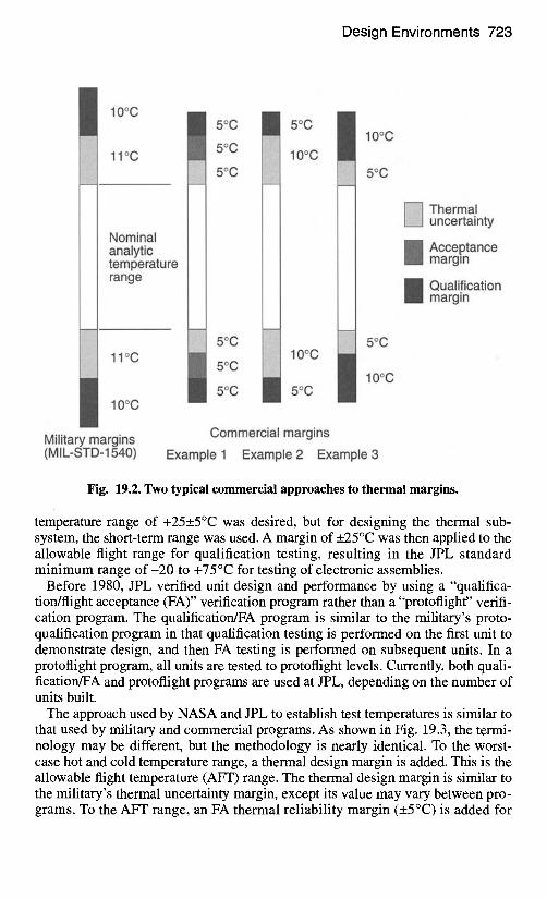
Contractors have established the temperature margin between the nominal extreme temperature range and the acceptance test temperature range differently. Several have reduced the margin to 10°C and termed it the thermal uncertainty margin or the acceptance margin. Others have broken this margin into a thermal uncertainty margin and an acceptance margin. A 5°C thermal uncertainty margin and a 5°C acceptance margin are common. The uncertainty margin is maintained throughout the program, despite confidence gained from flight data that might reduce the uncertainty in the analytic predictions. However, contractors are will- ing to reduce the acceptance margin to 0°C following thermal model correlation. A third approach is to use a 5°C thermal uncertainty margin with no additional mar- gin. Figure 19.2 compares these three approaches to the military practice.
The qualification margin has been nearly uniformly reduced from 10°C on mili- tary programs to 5°C for commercial programs, except in the case when the mar- gin between model prediction and acceptance temperatures is only 5°C. If com- mercial space vehicles are operated to qualification temperatures, then these margins have arguably different roles. Furthermore, qualification units are typi- cally more limited on commercial programs than on military programs, and the use of protoqualification or protoflight units is more common. Protoqualification margins on commercial programs have typically remained at 5°C, which is in agreement with the military program. Protoqualification test temperatures are therefore the same as qualification test temperatures for the first two commercial examples shown in Fig. 19.2.
In general, commercial thermal margins allow more risk than those in military programs, but the basic methodology for determining margins and the basic tech- niques for implementing them are similar in the two settings. The margins adopted by commercial contractors are in some cases very similar to military ones. For the most part, commercial contractors have experience with the military standards and understand how they were established.
NASA Thermal Margin and Unit Level Testing Practices In the 1960s the NASA Jet Propulsion Laboratory (JPL) established a short-
term allowable flight temperature range of +5 to +50°C for uncrewed lunar and planetary missions. The +5°C lower limit was just warmer than the freezing tem- perature of hydrazine, and the +50°C upper limit was based upon the tempera- ture of a fully sunlit electronics bay after one hour of heating. A long-term stable
Design Environments 723
10oc
11oc
Nominal analytic temperature range
11°C
10°C
I 5oc
10oc
10oc
5oc
10oc
5oc
5oc
10oc
~ Thermal uncertainty
Acceptance margin
Qualification margin
Military margins (MIL-STD-1540)
Commercial margins
Example 1 Example 2 Example 3
Fig. 19.2. Two typical commercial approaches to thermal margins.
temperature range of +25__.5°C was desired, but for designing the thermal sub- system, the short-term range was used. A margin of _+25°C was then applied to the allowable flight range for qualification testing, resulting in the JPL standard minimum range of - 2 0 to +75°C for testing of electronic assemblies.
Before 1980, JPL verified unit design and performance by using a "qualifica- tion/flight acceptance (FA)" verification program rather than a "protoflight" verifi- cation program. The qualification/FA program is similar to the military's proto- qualification program in that qualification testing is performed on the first unit to demonstrate design, and then FA testing is performed on subsequent units. In a protoflight program, all units are tested to protoflight levels. Currently, both quali- fication/FA and protoflight programs are used at JPL, depending on the number of units built.
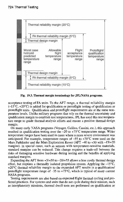
The approach used by NASA and JPL to establish test temperatures is similar to that used by military and commercial programs. As shown in Fig. 19.3, the termi- nology may be different, but the methodology is nearly identical. To the worst- case hot and cold temperature range, a thermal design margin is added. This is the allowable flight temperature (AFT) range. The thermal design margin is similar to the military's thermal uncertainty margin, except its value may vary between pro- grams. To the AFT range, an FA thermal reliability margin (+_5°C) is added for
724 Thermal Testing,
m
t
Thermal reliability margin (20°C)
I FA thermal reliability margin (5°C) ~; Thermal design margin l
/ Worst case Allowable / Flight hot/cold flight | acceptance predicted temperature | temperature temperature range / range range /
~ Thermal design margin l I FAthermal reliability margin (5°C)
~ Thermal reliability margin (15°C)
Protoflight/ qualification temperature
range
Fig. 19.3. Thermal margin terminology for JPL/NASA programs.
acceptance testing of FA units. To the AFT range, a thermal reliability margin (-15°C, +20°C) is added for qualification or protoflight testing of qualification or protoflight units. Qualification and protoflight requirements are at the same tem- perature levels. Unlike military programs that rely on the thermal uncertainty and qualification margin to establish test temperatures, JPL has used this test tempera- ture range to guide thermal analysis efforts and ensure a positive thermal design margin.
On many early NASA programs (Voyager, Galileo, Cassini, etc.), this approach resulted in qualification testing over the -20 to +75°C temperature range. Wider temperature ranges have been used in cases where a more severe environment was anticipated. For example, temperature ranges o f -55 to +70°C were used on the Mars Pathfinder and the Mars Exploration Rover (AFT -40 to +50 with-15/+20 margins). In special cases, such as sensors with temperature-sensitive materials, standard margins can be reduced. This change requires a trade-off between the risks of damaging sensitive hardware during testing and the benefits of applying standard margins.
Expanding the AFT from +5/+50 to -20/+55 allows a less costly thermal design effort, but requires a thermally isolated propulsion system. Applying the -15°C, +20°C thermal reliability margin to the expanded AFT results in a qualification/ protoflight temperature range of -35 to +75°C, which is typical of many current NASA programs.
Testing requirements are also based on expected flight thermal cycling and pre- ferred practices. For systems and units that do not cycle during their mission, such as interplanetary missions, thermal dwell tests are performed on qualification or
Development Thermal Testing 725
protoflight hardware over the described temperature range in a one-cycle thermal vacuum test of extended duration. For units that cycle during their mission, prac- tices similar to those in military programs are typically applied with an acceptance margin (_10°C) added to worst-case analytic temperature predictions. Also, at the unit level JPL typically requires thermal testing in a medium that simulates the mission environment (deep space vacuum or Mars pressure), whereas NASA has been more open to ambient thermal testing.
Development Thermal Testing Development tests are performed as required to accomplish the following objec- tives: • validation of new design concepts or application of proven concepts and tech-
niques to a new configuration • assistance in the evolution of designs from the conceptual phase to the opera-
tional phase • reduction of the risk in committing designs to the fabrication of qualification
and flight hardware • validation of qualification and acceptance test procedures • investigation of problems or concerns that arise after successful qualification
Development test requirements are necessarily unique to the test hardware and depend upon the objective of the test, the operational requirements of the specific program, and the maturity of the subsystems and units used. A common objective of development testing is to identify problems early in the design evolution so that any required corrective actions can be taken prior to starting formal qualification. Development tests verify design and performance margins, manufacturability, testability, maintainability, reliability, life expectancy, and compatibility with sys- tem safety. Where practical, development tests should be conducted over a range of operating conditions that exceed the design limits to identify marginal capabili- ties and marginal design features. The following sections describe objectives and processes for common thermal development tests.
Thermal Balance Test The thermal balance test is typically part of the system thermal vacuum test, although it can be performed on units and subsystems at lower levels of assembly. The thermal balance test has two objectives: obtaining thermal data for analytic thermal model correlation and verifying the thermal control subsystem. To pro- vide data for model correlation, individual conditions are simulated in the thermal vacuum chamber and thermal data are taken during temperature transition (for transient correlation) or at equilibrium (for steady-state correlation). A vehicle thermal balance test commonly includes simulations of hot operational phases, cold operational phases, cold nonoperational phases, transitions between condi- tions, and safe mode phases. Equilibrium temperatures or repeatable heater cycling profiles are typically the thermal data that are taken during the test. Verifi- cation of the thermal control subsystem includes performance verification of ther- mal hardware, including heaters, thermostats, flight thermistors, louvers, radiators, interface contact materials, heat pipes, and cryogenic systems. Temperature
726 Thermal Testing
and control authority margins are demonstrated from thermal data and hardware verification.
In nearly all cases, the thermal balance test is performed on flight hardware. Some testing at lower levels of assembly may require performing this test on non- flight hardware, such as a qualification unit or an engineering model. In such cases, the test hardware needs to consist of a thermal and structural equivalent of the flight equipment, to simulate that equipment's heat paths and thermal behav- ior. Further discussion of the thermal balance test is provided later in this chapter.
Thermal Mapping Test
For electronic units with high power levels or densities, a thermal mapping test is sometimes performed to verify their thermal characteristics. The test is basically a thermal balance test for a unit, slice, or printed wire board. It is performed in a thermal vacuum chamber possibly with an infrared (IR) camera. Objectives of the test are similar to those of the thermal balance test: obtain data for analytic ther- mal model correlation, verify the thermal control design, and establish confidence in the design and manufacturing processes. Specific concerns addressed in the thermal mapping are: (1) identification of hot spots on boards where power den- sity is locally high, (2) assessment of deviations from accepted design techniques for subsystem interconnects, part mountings, board sizes and thicknesses, number of board copper layers, thermal coefficients of expansion, or installation methods, (3) verification of boundary conditions, and (4) confirmation of interface heat transport capability.
Thermal Conductance Tests
Thermal conductance tests are performed whenever confidence is needed in the heat transport capability through a material or across an interface. Common appli- cations include an interface or material resistance, the directional conductivity in composite materials, the conductivity in vibration or thermal isolators, and the conductivity of cabling. Another is performance verification of thermal blankets, a test that is sometimes necessary when a highly resistive thermal blanket is speci- fied for an application. It may be required because analytic predictions of thermal blanket performance have high uncertainties. Setup is difficult because of the small mass of the blanket layers. In some situations, instead of measuring the blanket temperature, one measures the temperature of an adjacent surface and deduces the blanket temperatures from the thermal interaction between these two surfaces.
Photometric Test
The photometric test is performed with nonflight hardware scaled to the dimen- sions of the flight hardware, with the objective of assessing optical properties of the vehicle and solar interaction. The test is performed by allowing solar-wave- length-collimated illumination to fall incident upon the test article. Locations are identified on the test article where solar heating or reflections are of interest. Handheld scopes are used to measure the sun equivalences at those locations. The results are used to verify environmental flux calculations predicted by geometric models. Careful attention must be paid in the planning and execution of this test to
Unit Thermal Testing 727
ensure the accuracy of the scaled nonflight hardware, duplication of the surface finishes on the nonflight article, and use of identical procedures in the application of the surface finishes.
Deployment Mechanism Tests
Deployment mechanisms differ from other spacecraft units in that they are usually extremely critical to mission success and are mounted external to the vehicle, where thermal environments are severe. Deployment tests are commonly specified for these mechanisms to verify performance. In such tests, the simulation of harsh, but realistic, thermal environments is important. The tests are performed in hot and cold conditions as well as in an environment where the temperature is chang- ing or a temperature differential is induced. The concerns that arise during these tests include: (1) differential expansion of materials causing deployment failure, (2) thermal gradients arising within the mechanism causing binding during deployment, (3) material, adhesive, or lubricant thermal degradation at extreme hot or cold temperatures, and (4) interaction between thermal blankets interfering with deployment.
Heat Pipe Tests
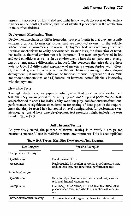
The high reliability of heat pipes is partially a result of the numerous development tests that they are subjected to for verifying workmanship and performance. Tests are performed to check for leaks, verify weld integrity, and demonstrate functional performance. A significant consideration for testing of heat pipes is the require- ment that they be tested in a horizontal or level configuration for performance ver- ification. A typical heat pipe development test program might include the tests listed in Table 19.3.
Unit Thermal Testing As previously stated, the purpose of thermal testing is to verify a design and ensure its successful use in realistic thermal environments. This is accomplished
Table 19.3. Typical Heat Pipe Development Test Program
Test Category Specific Examples
Heat pipe level testing
Qualification Acceptance
Burst pressure tests Radiographic inspection of welds, proof pressure test, helium leak test, and functional performance test
Pallet level testing
Qualification
Acceptance
Functional performance test, static load test, acoustic test, and thermal vacuum test Gas charge verification, full tube leak test, functional performance tests, acoustic test, and thermal vacuum test
Further development testing Aliveness test and in-gravity characterization test
728 Thermal Testing
by detecting flaws in the thermal design, materials, or manufacturing process, and by verifying that the unit tested performs within specifications during the test. Environmental stress screening is the process that subjects hardware to physical stresses and forces flaws that are not ordinarily apparent into observable failures. When these flaws are discovered, they are repaired, or problem equipment is replaced prior to flight. Ideally, qualification tests expose design defects, while acceptance tests uncover workmanship, part, material, and process defects. Perfor- mance verification is achieved when the item operates within specification when subjected to an extreme environment. These goals are generally accomplished most effectively at the unit level of testing.
To achieve effective ground testing, problems must be identified at the earliest practical point. Therefore, test levels and techniques are designed to maximize test rigor at the lowest levels of assembly and lessen in severity as the level of assem- bly increases. Problems are thus identified in time for orderly resolution and at a level of assembly that minimizes excessive teardown. For most spacecraft pro- grams, a systems engineering perspective toward the test flow begins at the unit level. This discussion will adopt such an approach and assume that high-quality parts have been procured and that adequate part testing has been performed.
In a time of increasing pressure to reduce program cost and schedule, unit level testing has been scrutinized heavily. Despite reliable data on the effectiveness of unit tests, particularly the thermal cycle and thermal vacuum test, the current trend in spacecraft development is to shorten or completely eliminate these tests, defer- ring their objectives to a higher level of assembly. This trend conflicts with the basic philosophy of testing presented in the previous paragraph and increases risk to the unit's flightworthiness. Testing should be viewed over the complete build process, beginning at the unit level and ending after the system level. With this perspective, one can better manage system risk and more readily realize deficien- cies in a unit's screening process.
Unit Thermal Tests
A unit is a functional item made up of modules and assemblies that are made up, in turn, of piece parts. Although tests and screens are conducted at lower levels of assembly, the lowest level addressed in most environmental specifications, test verification plans, and test practice manuals is the unit level. The three environ- mental thermal tests performed at the unit level are thermal vacuum, thermal cycling, and burn-in. Functional tests, which are not considered environmental tests, are performed at temperature extremes during thermal cycling and thermal vacuum.
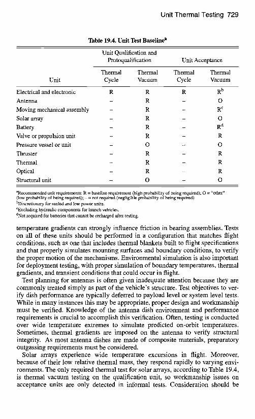
For various units, Table 19.4 (MIL-STD-1540) specifies which unit tests should be considered required, optional, and not required at the qualification and accep- tance levels. Regarding note (b) for unit thermal vacuum acceptance testing, most electronic units are unsealed, so this test would appear to be widely required. This note, however, also suggests that low power units do not require this test. Consid- erable effort has recently been devoted to understanding the implications of this note, and a more thorough explanation will be made later in this section.
Performance of moving mechanical assemblies can be extremely temperature- sensitive, as noted in the previous section. Binding of deployment mechanisms as the result of temperature or thermal gradients has occurred on orbit. Furthermore,
Unit Thermal Testing 729
Table 19.4. Unit Test Baseline a
Unit Qualification and Protoqualification Unit Acceptance
Thermal Thermal Thermal Thermal Unit Cycle Vacuum Cycle Vacuum
Electrical and electronic R R R R b
Antenna - R - O
Moving mechanical assembly - R - R c
Solar array - R - O
Battery - R - R d
Valve or propulsion unit - R - R
Pressure vessel or unit - O - O
Thruster - R - R
Thermal - R - R
Optical - R - R
Structural unit - O - O
aRecommended unit requirements: R = baseline requirement (high probability of being required); O = "other" (low probability of being required); - = not required (negligible probability of being required) bDiscretionary for sealed and low power units. CExcluding hydraulic components for launch vehicles. dNot required for batteries that cannot be recharged after testing.
temperature gradients can strongly influence friction in bearing assemblies. Tests on all of these units should be performed in a configuration that matches flight conditions, such as one that includes thermal blankets built to flight specifications and that properly simulates mounting surfaces and boundary conditions, to verify the proper motion of the mechanisms. Environmental simulation is also important for deployment testing, with proper simulation of boundary temperatures, thermal gradients, and transient conditions that could occur in flight.
Test planning for antennas is often given inadequate attention because they are commonly treated simply as part of the vehicle's structure. Test objectives to ver- ify dish performance are typically deferred to payload level or system level tests. While in many instances this may be appropriate, proper design and workmanship must be verified. Knowledge of the antenna dish environment and performance requirements is crucial to accomplish this verification. Often, testing is conducted over wide temperature extremes to simulate predicted on-orbit temperatures. Sometimes, thermal gradients are imposed on the antenna to verify structural integrity. As most antenna dishes are made of composite materials, preparatory outgassing requirements must be considered.
Solar arrays experience wide temperature excursions in flight. Moreover, because of their low relative thermal mass, they respond rapidly to varying envi- ronments. The only required thermal test for solar arrays, according to Table 19.4, is thermal vacuum testing on the qualification unit, so workmanship issues on acceptance units are only detected in informal tests. Consideration should be
730 Thermal Testing
given to simulating thermal conditions, at least temperature, during solar-array verification, because solder-joint flaws in the array wiring have been detected, and on occasion these workmanship errors are exposed after repeated cycling at tem- perature extremes.
The performance and life of batteries can strongly depend on temperature. In battery testing, the thermal control design is verified by demonstrating tempera- tures are within limits, temperature gradients are minimized (within individual cells, between cells, and between batteries), and thermal resistances at critical interfaces are as expected.
Unit Thermal Test Objectives Unit level thermal tests have three objectives: environmental stress screening, per- formance verification, and demonstration of survival and turn-on capability. The intent of environmental stress screening is to find faults inunit design, workman- ship, materials, and processes. Ideally, the qualification test should uncover design defects, while the acceptance test should uncover defects in workmanship, parts, materials, and processes. Performance verification is accomplished through func- tional tests conducted prior to, during, and after environmental tests. A unit must perform within specification requirements before the functional test can be deemed successful. The intent of the survival and turn-on objective is to demon- strate that equipment can be soaked or dwelled in a specific thermal environment, then started and operated at cold and hot survival or turn-on temperature limits without experiencing performance damage or performance degradation when returned to the operational temperature range.
With regard to these objectives, the thermal cycle test and the thermal vacuum test have different roles. The thermal cycle test is best suited to accomplishing environmental stress screening; demonstrating performance, survival, and turn-on capabilities is secondary. The reverse is true for thermal vacuum testing.
Unit Thermal Cycle Testing A unit's thermal cycle test demonstrates its ability to operate over the test temper- ature range. For qualification, the test demonstrates the unit's design and shows that the unit will endure the thermal cycle testing imposed during acceptance test- ing. At acceptance, the test detects material and workmanship defects prior to installation of the unit into a subsystem or vehicle. As shown in Table 19.4, ther- mal cycling should be performed on all electrical and electronic units. This is done primarily as an environmental stress screening. It is intended to enhance quality assurance by revealing latent defects in design, workmanship, and materials. Defects found in thermal cycling include loose connections, broken wire bonds, defective solder joints, inadequate stress relief, performance drift, bent connector pins, defective or contaminated parts, thermal-coefficient-of-expansion mis- matches, and material deficiencies.
Unit Thermal Cycle Test Parameters
The important parameters in achieving effective thermal cycle testing of units are temperature range, number of cycles, dwell or soak duration, rate of temperature change during transitions, and operational conditions.
Unit Thermal Testing 731
As discussed, unit level thermal cycle testing is performed at temperatures either based upon analytic predictions plus a thermal margin, or set at specific extremes, whichever values are more severe. At the acceptance level, either minimum to maximum expected temperatures (which includes the _+1 I°C thermal uncertainty margin) or cold and hot limits of -24 to +6 I°C are used. For example, if a unit has nominal expected temperature predictions of -18 to +42°C, the unit has minimum and maximum expected temperatures o f - 2 9 to +53°C. The hot temperature of +53°C is less severe than +61°C, so the acceptance test temperature range for this unit would be -29 to +6 I°C. At qualification, testing is performed at temperatures either 10°C colder than the minimum expected temperature and 10°C hotter than the maximum expected temperature, or at the specified extremes o f - 3 4 to +71°C. In the previous example, the qualification test temperatures would be -39 to +71°C.
The above discussion gives the general baseline procedure for establishing test temperatures at the unit level. If operational requirements prohibit testing over this temperature range, exception is made to the baseline procedure and testing is per- formed over the narrower operating temperature range. A risk assessment should be made on a unit-by-unit basis before the screening process is compromised.
Considerable work was performed in the 1970s and 1980s on the relationship between failure rates and number of cycles. Results showed that failures decreased with cycle count, sharply in the first few cycles and more gradually after a "knee in the curve" was achieved. Significant work was spent determining "knee" values and the appropriate number of cycles where infant mortality or a prescribed level of failures could be expected. Of particular note were studies performed by. Martin Marietta in 197219"3 and the Institute of Environmental Sciences in 1984.19"4 The research performed during these years aided in the establishment of test cycles for low-risk programs in the military standards.
For tailoring purposes, MIL-STD-1540C introduced the relationship between the number of cycles and the cycle temperature range:
(At I ZV, C2= CI~,AT2 ) (19.1)
where C 1 is the number of thermal cycles over temperature range AT 1, C 2 is the number of thermal cycles over temperature range AT 2, and N is a factor that depends on the stress level. Values of N have ranged from 1.4 for equivalent acceptance test programs (MIL-STD-1540C) to 2.6 for eutectic solder fatigue life demonstration. Typical values of N for electronics boxes are 2.0 to 2.6.
Recommendations for temperature rate of change are usually stated in maximal terms that take into account the chamber's capabilities. The location at which rate of change is measured is typically the same location at which the test temperature is recorded, such as the mounting point on the unit's baseplate for conductively cooled units or the unit's case for radiation-cooled units. Specific requirements for this parameter have been an average of 3 to 5°C per minute with a minimum of I°C per minute. Few data are available on the effect of different rates of change. Generally, faster transitions, at least as great as those expected during ascent or re- entry, should be adopted as a practice. For a special type of units, such as digital
732 Thermal Testing
computers, one might consider a slow temperature transition on the final cycle to permit repetitious functional checkout over a narrow temperature range.
Engineers usually agree that units need to be operational during environmental testing. Experience has shown that failure rates significantly increase for operat- ing, as compared to nonoperating, units. Beyond unit operation, performance should be monitored as much as possible throughout the test. In this manner, per- formance drift or anomalous readings can be detected. Hot and cold starts at oper- ational and survival limits have also proven to be effective stress screens, in addi- tion to demonstrating that the equipment is well designed and robust enough to survive mission-derived extreme environments and subsequently, to perform within specifications over the narrower operational temperature range. The pro- cess of performing hot and cold starts is discussed in the following section.
Finally, thermal dwell allows the unit to reach the test temperature. The require- ment is necessary to ensure that the unit will be tested at the designated tempera- ture extremes. Thermal dwell begins when the unit is within its test tolerance (typ- ically 3°C) and concludes just prior to the start of the functional performance test. Thermal dwell should be a minimum of one hour at the hot and cold temperature extremes on the first and last cycle and is not required on intermediate cycles.
Thermal soak is a specification for the total time spent at the hot or cold temper- ature extreme, to ensure that adequate time is spent in the thermal environment. MIL-STD-1540 recommends a minimum of six hours on the first and last cycles and one hour on intermediate cycles.
The unit level thermal cycle test parameters are shown in Table 19.5. The source of this data is MIL-STD-1540B. These values represent typical unit testing param- eters for current military programs.
Thermal Cycle Test Process
Prior to the test, a test plan must be available describing the procedures and the functional testing to be performed. Where practical, functional testing described in the test plan should be rehearsed with the unit at ambient temperature. The functional tests performed prior to (and following) the thermal cycle test should be identical to the functional tests that will be performed during the test.
Unit thermal cycling is typically performed in a thermal cycling chamber, where temperature-controlled dry air or gaseous nitrogen is used to heat or cool the unit. The nitrogen or dry air is used instead of ambient air to prevent moisture conden- sation on electronic parts or circuitry. During the heating cycle, the dry air or nitrogen is heated from the walls of the chamber. Usually direct heating need not be applied to the test article or to the mounting shelf. Cooling is accomplished by pumping liquid nitrogen through cooling tubes or coils mounted to the chamber baseplate. The baseplate is usually made of copper to provide good conduction over the interface with the test article. The environment is circulated with fans to prevent temperature gradients on the test article and to speed transitions in temper- ature. Baffles or flow directors are sometimes employed to better direct the circu- lating environment. When selecting a thermal chamber for a particular test, keep in mind that if relatively little room separates the internal walls of the chamber and the unit itself, air or gaseous nitrogen movement around the unit will be reduced. This may result in thermal gradients in the unit and a temperature-transition rate of change that is lower than desired.
Unit Thermal Testing 733
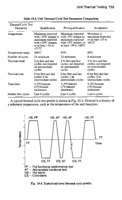
Table 19.5. Unit Thermal Cycle Test Parameter Comparison
Thermal Cycle Test Parameter Qualification Protoqualification Acceptance
Temperature
Temperature range
Number of cycles
Thermal dwell
Thermal soak
Transition
Minimum expected Minimum expected Minimum to with-10°C margin to with -5°C margin to maximum expected, maximum expected maximum expected or at least-24 to with +10°C margin, with +5°C margin, or +61°C or at least-34 to at least -29 to +66°C +71°C
105°C 95°C 85°C
24 minimum 24 minimum 8 minimum
1 hr first and last 1 hr first and last 1 hr first and last cycles; not required cycles; not required cycles; not required on intermediate on intermediate on intermediate cycles cycles cycles
6 hrs first and last 6 hrs first and last 6 hrs first and last cycles; 1 hr cycles; 1 hr cycles; 1 hr intermediate cycles intermediate cycles intermediate cycles
3-5°C/minute 3-5°C/minute 3-5°C/minute ( 1 °C/minute ( 1 °C/minute ( 1 °C/minute minimum) minimum) minimum)
Failure-free cycles Last 4 cycles Last 4 cycles Last 4 cycles
A typical thermal cycle test profile is shown in Fig. 19.4. Pictured is a history of a reference temperature, such as the temperature of the unit baseplate.
E
HS, FF HS, AF HS, AF HS, FF
r
FF
F Time
CS, FF CS, AF CS, FF
FF - Full functional performance test AF - Abbreviated functional test HS - Hot starts CS - Cold starts
Fig. 19.4. Typical unit level thermal cycle profile.
734 Thermal Testing
For the majority of the thermal cycling test, the unit is operating with its perfor- mance monitored. Scrutiny of performance parameters during the test enables the identification of latent defects and is therefore considered critical in ensuring effective testing. Prior to the formal start of testing, steps are taken to preclude the unwarranted accumulation of moisture within the unsealed unit. This is accom- plished by imposing a number of pretest cycles using dry air or nitrogen, where cold temperatures are not permitted to fall below the dew point of the air trapped within the unit. These pretest cycles purge moist air from internal spaces. To fur- ther reduce the risk of condensation, the test begins and ends with hot cycles or half-cycles. Prior to the test, a full functional performance test should be con- ducted to provide comparison data for results obtained during the test and to ensure that the unit is operating correctly before the environmental test begins.
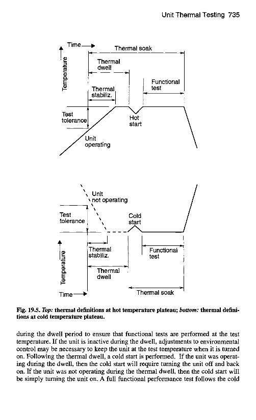
The test begins with the unit operating and the chamber environmental control set to the hot temperature level. After the test temperature sensor reaches the test tolerance temperature, the thermal dwell period begins. As shown in Fig. 19.5, the thermal-stabilization period is the time between the test tolerance (typically the test temperature minus 3°C) and the test temperature. During this period, adjust- ments are made to the environmental control to bring the test article to the test temperature. The thermal dwell begins at the onset of thermal stabilization to allow internal locations in the test article to reach the test temperature. Following the thermal dwell, which is typically a minimum of one hour on the first and last cycle of the test, the unit should be hot started by turning it off and back on. To prevent the test item temperature from dropping below the test tolerance, reacti- vating the unit should be done shortly after turnoff. Following the hot start, full functional tests are performed to verify the unit's performance within specifica- tion. The requirements of the functional test depend upon the purpose of the unit. The testing should demonstrate that the unit meets its performance requirements within acceptable tolerances. Thermal soak is the duration with the unit operating between the start of the thermal dwell and the end of the functional test.
Following the hot functional test, the chamber environment is reconfigured to the cold temperature phase. This involves turning off the chamber heater system and activating the liquid nitrogen cooling. To assist in more rapidly reaching the cold temperature, test plans have specified that the unit be nonoperating. This specification is subject to debate, because performance parameters should be monitored during the transient period. Stresses that build during transient condi- tions can be quite different in their effects, so hardware should be carefully watched during the cooling period. However, the unit is commonly turned off just prior to reaching a specified cold temperature. For acceptance tests, the unit may be nonoperational once the nominal expected temperature is reached and for qual- ification testing, once the acceptance temperature is reached.
Thermal stabilization, thermal dwell, and thermal soak have similar definitions at cold and hot temperatures. Thermal stabilization and thermal dwell begin when the temperature sensor reaches the test tolerance temperature (typically 3°C warmer than the test temperature). Adjustments are made to the environmental control during the thermal stabilization period to bring the test article to the cold test temperature, and the thermal dwell period ensures internal locations are at the cold test temperature before functional testing. In some cases the unit is activated
Unit Thermal Testing 735
Time
" Ii 0 [
Thermal soak
Thermal ~- dwell )l
Thermall ] stabiliz-I I I Functional
test
Test to
Unit . operating
Unit
Test tolerance
(1) Q .
E #-
not operating
Time ,-"
Thermal stabiliz.
Thermal dwell
Cold start
. . . . . / " ~ ,
I- Functional test
,= . . r !
Thermal soak
Fig. 19.5. Top: thermal definitions at hot temperature plateau; bottom: thermal defini- tions at cold temperature plateau.
during the dwell period to ensure that functional tests are performed at the test temperature. If the unit is inactive during the dwell, adjustments to environmental control may be necessary to keep the unit at the test temperature when it is tumed on. Following the thermal dwell, a cold start is performed. If the unit was operat- ing during the dwell, then the cold start will require turning the unit off and back on. If the unit was not operating during the thermal dwell, then the cold start will be simply turning the unit on. A full functional performance test follows the cold
736 Thermal Testing
start on the first and last cycles and should be nearly identical to the functional test performed at the hot temperature plateau.
Following the function test, the chamber environment is reconfigured to the hot environment, and as the temperature sensor passes through ambient, the first cycle is completed. The same procedure is repeated for the remaining cycles, with hot and cold starts performed at each temperature plateau. For intermediate cycles (those between first and last), abbreviated functional tests may be performed. These tests are subsets of the full functional performance test, and although they may be significantly shorter, they monitor key performance parameters and assess performance drift as the cycles accrue.
If a unit level thermal vacuum test is not being performed for a particular elec- tronic unit, then survival demonstration should be accomplished during the unit thermal cycle test. One or two cycles of the thermal cycle test are modified to increase the hot test temperature to the survival hot value and decrease the cold test temperature to the survival cold value. At the hot survival temperature, the unit should be hot started by turning it off and back on. The temperature of the environment can then be reduced to the acceptance or qualification temperature for dwell and functional testing. At the cold survival temperature, the unit is prob- ably off. Once that cold survival temperature is reached, the unit is cold-started. The environment can then be heated to the acceptance or qualification tempera- ture, or the unit may be heated by its power dissipation, with control of the environment.
Unit Burn-In Testing A necessary adjunct to the screening process is bum-in testing, during which the unit is operated for an extended period to precipitate failures. During burn-in, additional hours of operation beyond those accrued during unit thermal cycling and unit thermal vacuum testing are accumulated until a predetermined value is achieved. In this test, additional defects are precipitated, detected, and corrected, and failure-free performance is demonstrated. Because burn-in is a screen for workmanship errors, this test is only performed on acceptance units. According to MIL-STD-1540C, additional operation at the hot acceptance temperature is accu- mulated until the combined unit thermal cycling, thermal vacuum, and additional hot operation is at least 200 hours. The last 100 hours are to be failure-free, with 50 hours each on the primary and redundant sides.
Test plans have been proposed with bum-in testing at ambient temperature. These tests save considerable costs by not requiting a thermal chamber and by running units in parallel, but the stresses at ambient temperature are nearly negli- gible, so the screening effectiveness is extremely poor. Therefore, burn-in testing should only be performed in an environment that is, at minimum, the unit accep- tance temperature. Table 19.6 lists burn-in test parameter requirements from the military guidelines.
Unit Thermal Vacuum Testing The primary purpose of unit thermal vacuum testing is to verify the functional performance and design of the unit, although the test is still effective at stress screening. Without the convective environment, temperatures, thermal gradients,
Unit Thermal Testing 737
Table 19.6. Unit Burn-In Test Parameter Comparison
Thermal Cycle Test Parameter Thermal Cycle Test Parameter (MIL-STD-1540C)
Temperature
Total operating time
Failure-free hours
Maximum expected, or at least +61°C
200 hrs minimum, including thermal cycling and vacuum time
Last 100 hrs (50 hrs primary and 50 hrs redundant side)
and stresses will more closely simulate flight conditions than they do in the ther- mal cycle test. Thermal vacuum testing is vital in ensuring successful mission operation by demonstrating flightworthiness, workmanship, and design in the ground environment that best simulates on-orbit stresses. At the qualification level, the test verifies the unit design and demonstrates the ability of the unit to endure the thermal vacuum testing imposed on flight units during acceptance test- ing. At the acceptance level, the test detects material and workmanship defects and proves flightworthiness. In both tests, demonstration of operational performance is verified against specification requirements.
Unit Thermal Vacuum Test Parameters
The temperature range and extremes in the unit thermal vacuum test are identical to the thermal cycle test parameter requirements. Acceptance tests are performed at minimum and maximum expected temperatures, or at least-24 to +6 I°C, and qualification tests are performed at minimum and maximum expected temperature +_10°C, or at least-34 to +71°C. The number of cycles, however, is less, primarily because of the different objectives of the vacuum test and the fact that transition- ing in vacuum takes significantly longer. A comparison of the thermal vacuum test parameters from the military standards is given in Table 19.7. The source of this data is MIL-STD-1540B. The one acceptance cycle for electronic units (if eight thermal cycles are performed) is commonly increased to either two or four cycles in actual spacecraft test programs. It is also typical for the number of protoqualifi- cation cycles to be the same as the number of qualification cycles because design verification is a high priority of unit protoqualification testing.
Vacuum environments may necessitate longer dwell times than necessary in the thermal cycle test, because without the convective heat transfer, bringing the inter- nal part temperatures to the test level will take longer. Temperature sensors at locations away from the first sensor that reaches the test temperature should be monitored to estimate an appropriate dwell time. Furthermore, thermal analysis simulations can be performed to predict time required for internal parts to reach the test temperature after the unit's baseplate has reached the test temperature.
A pressure of 10 -4 torr (13.3 mPa) has been recommended in the military guide- lines. Low pressure is necessary to eliminate unrealistic effects of convective heat transfer in simulating thermal conditions encountered in space application, even at the molecular level. Achieving lower pressures where practical is highly desirable, especially for units that may require a longer-than-normal outgassing duration or
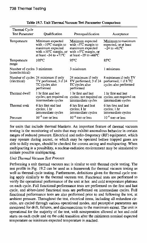
738 Thermal Testing
Table 19.7. Unit Thermal Vacuum Test Parameter Comparison
Thermal Cycle Test Parameter Qualification Protoqualification Acceptance
Temperature Minimum expected Minimum expected with-10°C margin to with-5°C margin to maximum expected maximum expected with + 10°C margin, or with +5°C margin, or at least-34 to +71°C at least-29 to +66°C
Minimum to maximum expected, or at least -24 to +61°C
Temperature 105°C 95°C 85°C range
Number of cycles 3 minimum (nonelectrical)
3 minimum 1 minimum
Number of cycles 24 minimum if only 24 minimum if only 8 minimum if only TV (electrical) TV performed; 3 if 24 TV performed; 3 if 24 performed; 1 if 8 TC
TC cycles also TC cycles also cycles also performed performed performed
Thermal dwell 1 hr first and last 1 hr first and last 1 hr first and last cycles; not required on cycles; not required on cycles; not required on intermediate cycles intermediate cycles intermediate cycles
Thermal soak 6 hrs first and last 6 hrs first and last 6 hrs first and last cycles; 1 hr cycles; 1 hr cycles; 1 hr intermediate cycles intermediate cycles intermediate cycles
Pressure 10 -4 torr or less 10 -4 torr or less 10 -4 torr or less
for units that include thermal blankets. An important feature of thermal vacuum testing is the monitoring of units that may exhibit anomalous behavior in certain ranges of reduced pressure. Electrical and radio-frequency (RF) equipment, which may operate during ascent, or which may be operated before trapped gases are able to fully escape, should be checked for corona arcing and multipacting. When multipacting is a possibility, a nuclear-radiation environment may be simulated to initiate possible multipacting.
Unit Thermal Vacuum Test Process
Performing a unit thermal vacuum test is similar to unit thermal cycle testing. The test profile in Fig. 19.2 can be used as a framework for thermal vacuum testing as well as thermal cycle testing. Furthermore, definitions given for thermal cycle test- ing apply similarly to the thermal vacuum test. Functional tests are performed to verify the operational performance of the unit at hot and cold temperature plateaus on each cycle. Full functional performance tests are performed on the first and last cycle, and abbreviated functional tests are performed on intermediate cycles. Full functional performance tests are also performed prior to and following the test, at ambient pressure. Throughout the test, electrical items, including all redundant cir- cuits, are cycled through various operational modes, and perceptive parameters are monitored for drift, failures, and disconnections to the maximum extent. The unit is operational for the majority of the test, with nonoperation allowed at hot and cold starts on each cycle and on the cold transition after the minimum nominal expected temperature or minimum expected temperature is reached.
Unit Thermal Testing 739
Survival and turn-on demonstration is particularly useful in the vacuum environ- ment, because it best simulates the flight conditions. As recommended in the ther- mal cycle test, one or two cycles may have their temperature levels extended for turn-on verification with performance operation at the acceptance or qualification level.
Unit thermal vacuum tests are divided for convenience into two categories: (1) those where conduction to a heat sink is the dominant mode of cooling, and (2) those where appreciable radiation to surroundings is possible or included in ther- mal analysis. The former has been the more likely scenario for electronics boxes. Conduction cooling is usually accomplished by mounting the unit onto a nearly isothermal heat sink. This type of mounting may not be representative of actual unit installation, which may for example have inserts in an aluminum honeycomb with facesheets. It is usually acceptable, however, provided the differences between test mounting and flight mounting are accounted for by analysis and ver- ified by testing at the system or the subsystem level. If the component is cooled primarily or appreciably by radiation or by both conduction and radiation, control of heat paths becomes very important. Radiation and conduction paths are simu- lated and controlled so that heat loss by these different modes occurs in approxi- mately the same proportion as would be calculated for the flight environment. This simulation is necessary so that piece-part temperatures and unit thermal gradients duplicate those that occur in actual usage.
Waiving Thermal Vacuum Testing for Electronics Boxes
Testing provides confidence in the design and workmanship of the test article. Whenever a test is waived, engineers generally agree that either (1) the objectives of this test have already been met in a previous test or should be met in a subse- quent test, or (2) the hardware is insensitive to the test environment. Where these deletions make sense, significant time can be saved and significant costs can be eliminated.
The objective in proposing a test waiver is to manage risk. Elimination of a low- level test defers risk to a higher level of assembly. Should a unit fail at the system level, the impact to cost and schedule to fix the failure increases dramatically. As a result, proposals to delete low-level testing must be reviewed carefully to ensure proper risk management. The difficulty is in the determination of how much design and workmanship risk is carded to the higher level of assembly with the elimination of a low-level test.
One test that can be extremely expensive is the thermal vacuum test. Militar-y testing standards state that acceptance thermal vacuum testing of low power elec- tronic units is discretionary. The rationale is that low power units have thermal characteristics that are more dependent on their environment than on their own power generation. A low power unit may be vacuum-insensitive in that internal piece part temperatures should be nearly the same in the thermal cycle test as they would be in the thermal vacuum test. Thermal cycles, however, cannot be simply substituted for thermal vacuum cycles. The tests have different objectives, and common purposes are accomplished by different means and with different effi- ciencies. As a result, careful consideration must be given to the objectives of these tests so that risks are reduced and not pushed to a higher level of assembly.
740 Thermal Testing
Despite a full array of unit level testing, experience shows that unit level failures still occur at the subsystem and system level. Therefore, where stress screens are most likely to uncover design or workmanship deficiencies, these tests should be maintained, not eliminated. Any deferment of a test screen must be done with ade- quate knowledge of the unit's design, performance, and heritage. For example, the performance of RF units is inherently temperature (and vacuum) sensitive, so ther- mal vacuum testing should not be waived for RF units. Furthermore, thermal vac- uum and thermal cycle testing should be considered for all mission-critical units, regardless of power dissipation, to ensure operational success. Thermal vacuum testing should also be performed for units that: • are or have parts that are pressure sensitive • are temperature controlled to maintain performance within a narrow tempera-
ture range, • have hermetically sealed items for which deflections under worst-case condi-
tions could result in shorts with nearby items, • have high voltages with corona or multipaction concerns • have high localized power densities • have case temperature predictions significantly hotter in vacuum than in air • are of a new design with little or no flight heritage
The intent of these considerations is to enable a technical risk assessment for deferring the vacuum environment. In some instances thermal cycling in lieu of the thermal vacuum may be acceptable. When it can be shown that thermal vac- uum effects are small and that heat paths are well understood, such as might occur for units with low power dissipation or with robust conductive heat transfer paths, the benefits of deferring the vacuum environment to a higher level of assembly may outweigh the associated risks. Unit assessment, however, is unique and must be handled on a unit-by-unit basis.
Commercial Practices for Unit Testing
Generally, commercial practices differ from military practices primarily in the number of cycles performed and the requirement for thermal vacuum and thermal cycle testing. Whereas military programs emphasize the need for unit level testing both in thermal vacuum and in ambient thermal cycling, commercial programs tend to perform either vacuum or cycling tests for units. The number of cycles in a commercial program is given as the total unit level thermal test cycle count and is less than the number recommended in the military standards. For example, instead of the 12 acceptance thermal cycles (8 thermal cycling plus 4 thermal vacuum) typical of a military program, a commercial program might perform 8 total cycles, either all in air or all in vacuum. Usually, the number of protoqual cycles is nearly the same as the number of acceptance cycles. The number of qualification cycles is typically higher than the number of acceptance cycles, but not greatly higher. Instead of 27 unit thermal cycles at qualification (24 thermal cycling plus 3 ther- mal vacuum), a commercial program would propose perhaps 10 to 12 total cycles.
Other commercial test parameters do not differ greatly from their military coun- terparts. Several commercial contractors continue to use standard acceptance
Unit Thermal Testing 741
temperature ranges of -24 to +6 I°C. In some cases, payload electronics are tested within narrower temperature ranges as a result of performance constraints. Com- mercial practice regarding temperature margins was previously addressed.
Bum-in has been reduced by a number of commercial contractors. Differences vary greatly between contractors, but they include a lower number of hours in test, the elimination of redundant side operation, and an increased desire to perform the test at ambient temperature. Such compromises are not supported by published data on the subject of stress screening effectiveness. Depending on the power dis- sipation of the unit, ambient air burn-in testing can have almost negligible benefit to screening for failures.
On the whole, the level of stress screening is lower in commercial unit thermal testing than in military unit thermal testing. With the reduction in the number of cycles performed, the overall test effectiveness is lower. In theory, undetected fail- ures at the unit level should result in an increased failure rate at higher levels of assembly (subsystem and system), but this has not generally been the case. One could conclude that the unit thermal testing performed on commercial satellites is therefore adequate and the military practices are excessive. Another argument, however, is that system level testing is not stressful or perceptive enough to catch these failures.
NASA Practices for Unit Testing
Of the many agencies in the aerospace community, NASA has promoted "better, faster, cheaper" practices more than any other. NASA and the Jet Propulsion Lab- oratory have performed considerable work to quantify test effectiveness and risk reduction for their space programs. Although risk trade-off guidelines and pre- ferred practices have been written to provide test requirements for NASA pro- grams, unit testing procedures vary between programs, so the follow paragraphs discuss typical practices.
As previously mentioned, unit testing is categorized between those that thermal cycle in flight (generally over a temperature range greater than 20°C, environmen- tally or power-cycling induced) and those that do not. For units that cycle in flight, thermal cycling includes two to ten thermal cycles (typically eight) over the appropriate temperature range. A distinction is not made between vacuum and air cycles, but rather the practices state that thermal cycling should be performed in a vacuum if the test item is designed to operate in a vacuum.
For units that do not cycle, thermal cycling includes one thermal cycle over the appropriate temperature range. The rationale for a single cycle test has commonly been that deep space NASA programs do not experience the same level of temper- ature cycling as compared to Earth-orbiting spacecraft. Thermal dwell tests are performed on protoflight hardware over the temperature range o f - 2 0 to +75°C. Performance demonstration is conducted at the cold temperature for 24 h and at the hot temperature for 144 h. Testing in vacuum is preferred to ambient air test- ing. Other test practices are very similar to military program procedures.
742 Thermal Testing
Subsystem and Payload Thermal Testing Subsystem and payload level testing are performed after unit level testing, but before system level testing. These tests provide additional environmental stress screening, performance verification, and thermal balance. Generally, the objec- tives are more closely related to system level requirements than to unit level requirements. This alignment agrees with the philosophy that early detection of problems is desirable.
Many advantages may be gained by testing at the subsystem level as compared to the system level, including the following. • Subsystem tests allow use of smaller test facilities and make it easier to tailor
the thermal environment to the specific requirements of the test article. • Configuration and heat pipe leveling requirements can be more readily met. • The subsystem and its units are more accessible. • Less interference with adjacent payloads, hardware, and test equipment is
observed. • Boundary conditions are better understood. • Problems are easier to isolate. • Data and instrumentation may be more thorough. For example, thermal bal-
ance model correlation may be easier because more thermocouples may be available for gathering thermal data.
• The retest time can be significantly shorter. • Design and performance results are obtained in a more timely manner, and
problems discovered at this level are significantly easier to correct. • In some cases, the subsystem test suffices to demonstrate or prove some
aspects of the design (e.g., thermal balance), when the test cannot be con- ducted in a meaningful way at the system level.
• Performance testing can be more thorough. Confidence is also gained, in that performance requirements are more easily demonstrated at the system level if they have been shown previously in the subsystem level.
In proposing a subsystem or payload test, one typically applies system level requirements, because the test's goals are usually system level objectives. Thermal testing parameters are therefore identical at the subsystem and system levels. In thermal tests, temperature ranges should be as wide as practical, possibly wider than what will be obtained at the system level.
System Thermal Testing Also known as space vehicle level testing, system level testing has an emphasis very different from testing at the unit or subsystem level. As the final ground veri- fication of system and unit performance in a realistic flight environment, system level testing focuses not on individual unit functionality, but rather on end-to-end performance verification of subsystems and mission requirements. Specifically, interfaces between units and subsystems are assessed, continuity of mission objec- tives is demonstrated, compatibility of different subsystem requirements is shown, and flightworthiness of the vehicle is proven.
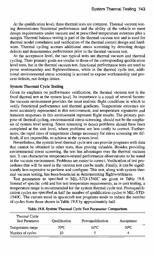
System Thermal Testing 743
At the qualification level, three thermal tests are common. Thermal vacuum test- ing demonstrates functional performance and the ability of the vehicle to meet design requirements under vacuum and at prescribed temperature extremes plus a margin. Thermal balance testing is part of the thermal vacuum test and is used for thermal model correlation and verification of the thermal control design and hard- ware. Thermal cycling accrues additional stress screening by detecting design defects and demonstrates performance prior to the thermal vacuum test.
At the acceptance level, the two typical tests are thermal vacuum and thermal cycling. Their primary goals are similar to those of the corresponding qualification level tests, but in the thermal vacuum test, functional performance tests are used to prove workmanship and flightworthiness, while in the thermal cycle test, addi- tional environmental stress screening is accrued to expose workmanship and pro- cess defects, not design issues.
System Thermal Cycle Testing
Given its emphasis on performance verification, the thermal vacuum test is the focal thermal test at the system level. Its importance is a result of several factors: the vacuum environment provides the most realistic flight conditions in which to verify functional performance and thermal gradients. Temperature extremes are most accurately represented in this environment, and temperature signatures and transient responses in this environment represent flight results. The primary pur- pose of thermal cycling, environmental stress screening, should not be the empha- sis of system level testing. Stress screening to detect problems should have been completed at the unit level, where problems are less costly to correct. Further- more, the rapid rates of temperature change necessary for stress screening are dif- ficult, if not impossible, to achieve at the system level.
Nevertheless, the system level thermal cycle test can provide programs with data that cannot be obtained in other tests, thus proving valuable. Besides providing environmental stress screening, the test has advantages over the thermal vacuum test. It can characterize temperature-related performance observations to be noted in the vacuum environment. Problems are easier to correct. Verification of test pro- cedures that will be used in the vacuum test can be made. Finally, it can be signif- icantly less expensive to perform and configure. This test, along with system ther- mal vacuum testing, has been beneficial in demonstrating flightworthiness.
Test parameters as specified in MIL-STD-1540C are given in Table 19.8. Instead of specific cold and hot test temperature requirements, as in unit testing, a temperature range is recommended for the system thermal cycle test. Protoqualifi- cation cycles are specified as half the number of qualification cycles in MIL-STD- 1540C. The current trend in spacecraft test programs tends to reduce the number of cycles from those shown in Table 19.8 by approximately half.
Table 19.8. System Thermal Cycle Test Parameter Comparison
Thermal Cycle Test Parameter Qual i f icat ion Protoqualification Acceptance
Temperature range 70°C 60°C 50°C
Number of cycles 10 5 4
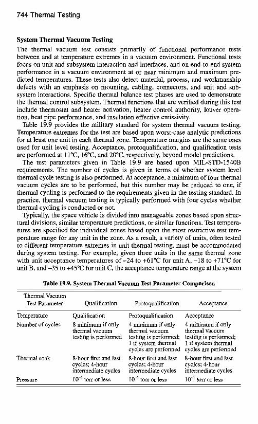
744 Thermal Testing
System Thermal Vacuum Testing
The thermal vacuum test consists primarily of functional performance tests between and at temperature extremes in a vacuum environment. Functional tests focus on unit and subsystem interaction and interfaces, and on end-to-end system performance in a vacuum environment at or near minimum and maximum pre- dicted temperatures. These tests also detect material, process, and workmanship defects with an emphasis on mounting, cabling, connectors, and unit and sub- system interactions. Specific thermal balance test phases are used to demonstrate the thermal control subsystem. Thermal functions that are verified during this test include thermostat and heater activation, heater control authority, louver opera- tion, heat pipe performance, and insulation effective emissivity.
Table 19.9 provides the military standard for system thermal vacuum testing. Temperature extremes for the test are based upon worst-case analytic predictions for at least one unit in each thermal zone. Temperature margins are the same ones used for unit level testing. Acceptance, protoqualification, and qualification tests are performed at 11°C, 16°C, and 20°C, respectively, beyond model predictions.
The test parameters given in Table 19.9 are based upon MIL-STD-1540B requirements. The number of cycles is given in terms of whether system level thermal cycle testing is also performed. At acceptance, a minimum of four thermal vacuum cycles are to be performed, but this number may be reduced to one, if thermal cycling is performed to the requirements given in the testing standard. In practice, thermal vacuum testing is typically performed with four cycles whether thermal cycling is conducted or not.
Typically, the space vehicle is divided into manageable zones based upon struc- tural divisions, similar temperature predictions, or similar functions. Test tempera- tures are specified for individual zones based upon the most restrictive test tem- perature range for any unit in the zone. As a result, a variety of units, often tested to different temperature extremes in unit thermal testing, must be accommodated during system testing. For example, given three units in the same thermal zone with unit acceptance temperatures o f - 2 4 to +61°C for unit A , - 1 8 to +71°C for unit B, and -35 to +45°(2 for unit C, the acceptance temperature range at the system
Table 19.9. System Thermal Vacuum Test Parameter Comparison
Thermal Vacuum Test Parameter Qualification Protoqualification Acceptance
Temperature
Number of cycles
Thermal soak
Pressure
Qualification
8 minimum if only thermal vacuum testing is performed
8-hour first and last cycles; 4-hour intermediate cycles
10 -4 torr or less
Protoqualification Acceptance
4 minimum if only 4 minimum if only thermal vacuum thermal vacuum testing is performed; testing is performed; 1 if system thermal 1 if system thermal cycles are performed cycles are performed
8-hour first and last 8-hour first and last cycles; 4-hour cycles; 4-hour intermediate cycles intermediate cycles
10 -4 torr or less 10 -4 torr or less
System Thermal Testing 745
level for this thermal zone would be -18 to +45°C. In this example, relatively wide unit temperature ranges of 85°C, 89°C, and 80°C were reduced to 63°C at the sys- tem level. This example illustrates the importance of unit testing to similar temperatures.
Another common approach is to base thermal-zone temperatures not on the acceptance temperatures of the units, but on their worst-case temperature predic- tions. In the above example, unit A may have been tested at the unit level to -24 to +6 I°C, but it may have a worst-case nominal temperature prediction range of 0 to +40°C. The thermal uncertainty margin would be added to this range, so for an 11°C margin, testing of this unit would at most be -11 to +5 I°C. This range would then be compared to the range of other units within the same thermal zone, so the 63°C range would likely be reduced even further.
The approach of the system thermal vacuum test with regard to achieving tem- perature is to drive as many units as possible, but at least one unit per vehicle ther- mal zone, to their qualification or acceptance temperature extreme, with the con- straint that no unit should exceed its unit level test temperatures. Temperatures are continuously monitored to avoid overstressing or exceeding unit temperature lev- els. The system level test temperature approach (applying a margin to worst-case predictions) is identical to that at the unit level, except that the default values (-24 to +6 I°C for acceptance and-34 to +7 I°C for qualification) do not apply. To assist in not exceeding unit temperature limits, an additional test tolerance of typically 3 to 5°C is applied at both cold and hot temperatures. In the example given, func- tional testing would begin when the first thermistor or test thermocouple in that thermal zone reached a temperature below-13°C or above +40°C.
In this example, with test tolerances applied, the total test range has been reduced to only 53°C. System level test temperatures frequently are relatively benign as compared to the unit temperatures. In some cases, the hot test tempera- ture for several thermal zones approaches room temperature levels. Thermal stresses over this temperature range are much smaller as compared to the stress levels that may have resulted over a wider temperature range at the unit level. This reduction in testing effectiveness must be remembered when considering the elim- ination of unit testing.
Another feature of system level testing that restricts the ability of the test to reach test temperature is chamber and vehicle limitations. In some cases, the chamber or heater lamps are not capable of driving a thermal zone to its test tem- perature. More commonly, interactions between thermal zones or restrictions of adjacent zones prevent the achievement of test temperatures. Table 19.10 com- pares test temperatures achieved during unit- and system level testing for an actual spacecraft. Payload panels 5-8 were tested to near-acceptance temperatures, but all other thermal zones had significantly smaller temperature ranges. These results are representative of results obtained on other programs.
The standards recommend an eight-hour thermal soak. For large spacecraft with extensive functional testing, the soak period will be perhaps a couple of weeks. No requirement is given for thermal dwell, but bringing the spacecraft to equilibrium prior to functional testing should be part of the test procedures.
Full functional performance tests are performed before and after the thermal vacuum test at ambient temperatures and pressure, and at cold and hot temperature
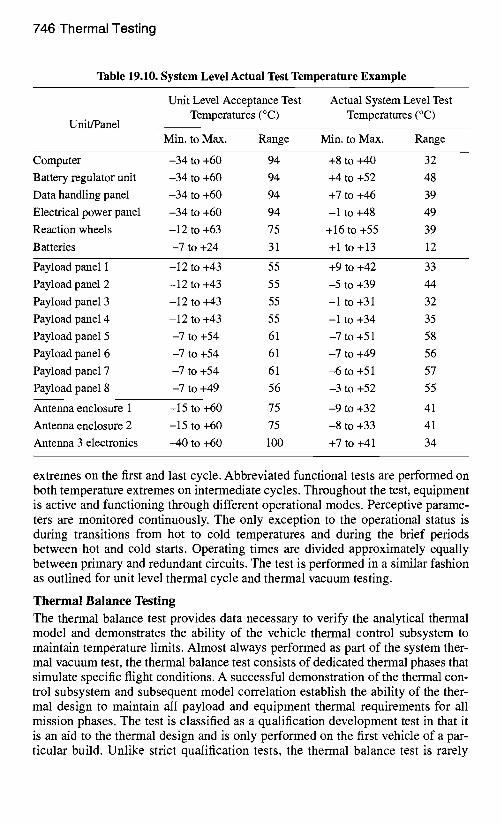
746 Thermal Testing
Table 19.10. System Level Actual Test Temperature Example
Unit/Panel
Unit Level Acceptance Test Temperatures (°C)
Actual System Level Test Temperatures (°C)
Min. to Max. Range Min. to Max. Range
Computer -34 to +60 94 +8 to +40 32
Battery regulator unit -34 to +60 94 +4 to +52 48
Data handling panel -34 to +60 94 +7 to +46 39
Electrical power panel -34 to +60 94 -1 to +48 49
Reaction wheels -12 to +63 75 + 16 to +55 39
Batteries -7 to +24 31 +1 to +13 12
Payload panel 1 -12 to +43 55 +9 to +42 33
Payload panel 2 -12 to +43 55 -5 to +39 44
Payload panel 3 -12 to +43 55 -1 to +31 32
Payload panel 4 -12 to +43 55 -1 to +34 35
Payload panel 5 -7 to +54 61 -7 to +51 58
Payload panel 6 -7 to +54 61 -7 to +49 56
Payload panel 7 -7 to +54 61 -6 to +51 57
Payload panel 8 -7 to +49 56 -3 to +52 55
Antenna enclosure 1 -15 to +60 75 -9 to +32 41
Antenna enclosure 2 -15 to +60 75 -8 to +33 41
Antenna 3 electronics -40 to +60 100 +7 to +41 34
extremes on the first and last cycle. Abbreviated functional tests are performed on both temperature extremes on intermediate cycles. Throughout the test, equipment is active and functioning through different operational modes. Perceptive parame- ters are monitored continuously. The only exception to the operational status is during transitions from hot to cold temperatures and during the brief periods between hot and cold starts. Operating times are divided approximately equally between primary and redundant circuits. The test is performed in a similar fashion as outlined for unit level thermal cycle and thermal vacuum testing.
Thermal Balance Testing The thermal balance test provides data necessary to verify the analytical thermal model and demonstrates the ability of the vehicle thermal control subsystem to maintain temperature limits. Almost always performed as part of the system ther- mal vacuum test, the thermal balance test consists of dedicated thermal phases that simulate specific flight conditions. A successful demonstration of the thermal con- trol subsystem and subsequent model correlation establish the ability of the ther- mal design to maintain all payload and equipment thermal requirements for all mission phases. The test is classified as a qualification development test in that it is an aid to the thermal design and is only performed on the first vehicle of a par- ticular build. Unlike strict qualification tests, the thermal balance test is rarely
System Thermal Testing 747
performed on qualification hardware, but rather on flight hardware, namely on the lead vehicle of a series of spacecraft and on a block change in a series of vehicles.
The test involves simulating several mission phases with one or more vehicle configurations. On-orbit phase simulations may include several combinations of equipment operation and solar angle heating profiles. Unlike the thermal vacuum test, where equipment is driven to specific test temperatures, the thermal balance test uses a known environment (heater settings, chamber cold wall) and preset operational status to simulate the test phase. The vehicle is then allowed to achieve its equilibrium temperature for that environment. Other simulations may include transient conditions where the vehicle starts at an equilibrium condition and the environment and operational status are changed to reflect a flight condition, such as eclipse cooldown or ascent.
A baseline thermal balance test should consist of a set of phases that includes one or two hot operational phases, a cold operational phase, and a cold nonopera- tional phase. The hot phases will have high, but realistic, levels of equipment usage and absorbed environmental heating. The test frequently includes two hot phases, each with environmental heating on different sides of the spacecraft. The cold phases will involve minimal equipment usage, bus voltage, and environmen- tal heating. The operational phases are intended to verify that unit operational temperature limits are maintained under different environmental conditions. The cold nonoperational phase is intended to demonstrate nonoperational temperature limits and verify heater operation. The test phases do not need to simulate the worst-case conditions expected on orbit, but they should stress the thermal control hardware so that confidence is gained in its flightworthiness. Using extreme con- ditions for thermal model correlation is important, so that flight predictions are not a significant extrapolation beyond the test simulation phases.
For higher-priority spacecraft, the baseline thermal balance test should be expanded to include such simulations as eclipse, ascent, transfer orbit, and safe mode. The test should also include a verification phase in which temperature data are taken at equilibrium and compared to analytic predictions after thermal model correlation has been completed. Temperature data from this phase are not used in the correlation, but rather as a check of the correlation.
Thermal Balance Test Process
Figure 19.6 illustrates a relatively simple thermal balance test profile. Thermal balance testing is almost always performed as part of the thermal vacuum test. It typically precedes the thermal vacuum test, so that if the thermal balance test must be halted and changes made to the thermal design, the integrity of the thermal vac- uum verification is not compromised.
The test begins with closing the chamber door and evaluating the chamber air. Sometimes the pressure is reduced below 10 -4 torr before the chamber walls are cooled to ensure that the door is sealed properly. Pressures lower than this are typ- ical, especially if thermal blankets are in the chamber or if materials need to be outgassed. The walls are cooled with liquid nitrogen loops to simulate the space environment. In Fig. 19.6, the first thermal balance phase plotted is a cold opera- tional phase. Some contractors prefer to begin the test with a cold phase, in order
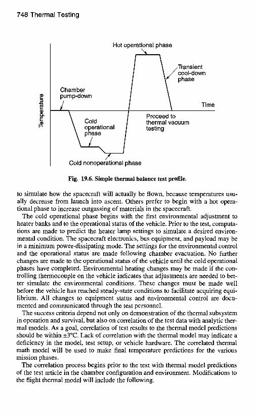
748 Thermal Testing
:3
tl)
E #_
Hot operational phase
Chamber pump-down
/ Cold operational phase /
\ /
Cold nonoperational phase
\
/T rans ien t cool-down phase
Time
Proceed to thermal vacuum testing
Fig. 19.6. Simple thermal balance test profile.
to simulate how the spacecraft will actually be flown, because temperatures usu- ally decrease from launch into ascent. Others prefer to begin with a hot opera- tional phase to increase outgassing of materials in the spacecraft.
The cold operational phase begins with the first environmental adjustment to heater banks and to the operational status of the vehicle. Prior to the test, computa- tions are made to predict the heater lamp settings to simulate a desired environ- mental condition. The spacecraft electronics, bus equipment, and payload may be in a minimum power-dissipating mode. The settings for the environmental control and the operational status are made following chamber evacuation. No further changes are made to the operational status of the vehicle until the cold operational phases have completed. Environmental heating changes may be made if the con- trolling thermocouple on the vehicle indicates that adjustments are needed to bet- ter simulate the environmental conditions. These changes must be made well before the vehicle has reached steady-state conditions to facilitate acquiring equi- librium. All changes to equipment status and environmental control are docu- mented and communicated through the test personnel.
The success criteria depend not only on demonstration of the thermal subsystem in operation and survival, but also on correlation of the test data with analytic ther- mal models. As a goal, correlation of test results to the thermal model predictions should be within _+3°C. Lack of correlation with the thermal model may indicate a deficiency in the model, test setup, or vehicle hardware. The correlated thermal math model will be used to make final temperature predictions for the various mission phases.
The correlation process begins prior to the test with thermal model predictions of the test article in the chamber configuration and environment. Modifications to the flight thermal model will include the following.
System Thermal Testing 749
• the removal of hardware that will not be in the thermal chamber, such as solar arrays and propellant in tanks and lines
• the addition of thermal nodes for the representation of test hardware, including chamber walls, heater lamps, test stands, and equipment for payload testing
• the addition of thermal nodes for cabling with guard heater • changes to power-dissipation levels and environments to reflect the test phase
conditions • changes to the radiation view factors to account for beginning-of-life surface
properties and blockage resulting from test equipment and stowed hardware In many cases, when the test configuration and test hardware do not resemble
flight conditions, the geometric math model must be modified and run to compute view factors from the test article to the various test hardware surfaces. Test equip- ment may interfere with the view from the spacecraft to the chamber wall, so that its view factor is significantly reduced. The test condition view factors replace the flight view factors in the thermal model.
Once the thermal model is developed for the test conditions, temperature and heater power data are predicted for the various test phases in which correlation data are taken. These predictions are made prior to testing, so that during the test, an initial qualitative assessment can be made.
During the test, temperatures are allowed to stabilize during the correlation test phases so that reliable steady-state data are obtained. The thermal stability requirement for thermal balance testing is more stringent than it is for thermal cycle and thermal vacuum testing. The requirement commonly specifies that ther- mal stabilization should be achieved when the rate of temperature change is less than I°C per hour, as measured over four hours. In addition to this criterion, engi- neering judgment is important. If a thermocouple is changing by I°C per hour, but the rate of change appears constant, then the temperature has not stabilized. Verifi- cation that the rate of change is decreasing is also important, to ensure that the temperature is approaching a steady-state value.
For thermal zones cycling on heaters, the above criterion is not applicable, and yet verification of the repeatability of the heater duty cycle is important. A com- mon criterion for heater activity is to demonstrate that the heater duty cycle is within 10% of its previous cycle. This goal is usually achieved by comparing cycle durations. In some cases, however, this criterion cannot be met. When heat- ers interfere with each other such that a clear, repeatable duty cycle does not occur, then engineering judgment must be used to assess whether the thermal zone has achieved equilibrium.
Because thermal vacuum testing can be extremely expensive, one tends to move to the next phase before all test thermocouples have completely stabilized. Fur- thermore, the time spent waiting for the final thermocouples to reach the criterion is usually a time of inactivity for all test-support personnel. However, long periods of inactivity are by nature part of thermal testing, and shortcuts will result in uncertainties in the correlation activity because they prevent proper achievement of the stabilized temperature. Experienced thermal engineers insist on soak dura- tions after the criterion has been achieved to verify that temperatures are tending toward an equilibrium condition.
750 Thermal Testing
Once thermal data have been derived from a particular test phase, the thermal model correlation may begin. The thermal balance test need not be completed before correlation work is done. These activities can be performed in parallel, pro- vided personnel are available. In fact, early model confirmation has advantages. Observations made during initial correlation activity can be checked during subse- quent thermal balance test phases.
The first step in model correlation is running the thermal model with updated chamber conditions. Typically, the values of the bus voltage, lamp settings, cham- ber wall temperature, and operational status are slightly different than the values assumed for those parameters prior to the test. Rerunning the model will update temperature and heater power predictions for a better comparison.
The next step is to compare the model predictions with the test data. This should be done for a single test phase, typically a steady-state hot or cold phase without a majority of heaters operating. Thermal zones with large temperature discrepancies are worked first. Test conditions are reverified and obvious model omissions are checked. If these actions do not correct a problem, then the thermal model is adjusted in a direction chosen to make the temperature predictions agree with test data. Usually, heat transfer paths are altered with modifications to conduc- tances and view factors. These changes should only be made on paths that have relatively high uncertainties, such as paths across interfaces or in complex geometries.
Changes should also be minor. Rarely are major changes made to a model. For example, a spacecraft thermal blanket should have an e* value between 0.015 and 0.060, and changing a value to something else suggests that other sources of error need to be investigated. Significant changes many times indicate a thermal model lacks sufficient detail. Changes also have to agree with the hardware design. Radi- ator areas and thermal mass must reflect the flight configuration. Material proper- ties should be confirmed before they are altered.
After major discrepancies are resolved, the reconciliation process continues with other discrepancies greater than _+3°C. When the correlation is completed for the first test phase, the procedure is repeated for a second test phase. Care must be taken when changes are made in subsequent test phase correlations to ensure that the first-phase correlation is maintained. In many instances, the first-phase simula- tion will need to be repeated to ensure that subsequent changes to the model have not undone the correlation. When all temperature predictions have been brought to within _3°C for all correlation phases, the thermal model is said to be correlated.
In practice, individual locations or regions of the thermal model may not corre- late to within _3°C. Inadequate knowledge of test conditions, uncertainty in how heater lamps may be interfering, and a lack of understanding of how payloads or equipment items interact are prevalent reasons as to why this may occur. In these cases, little can be done to improve correlation without guessing at conditions or adding larger uncertainties to the thermal model. The better practice is to keep the larger correlation errors and provide an explanation as to why the correlation can- not be brought to within _3°C.
If the cause is insufficient detail or fidelity in the thermal model, then the model should be corrected to accurately reflect the heat transfer paths and phys- ical geometry. Areas where detail is lacking typically have large temperature
System Thermal Testing 751
differences between nodes or carry a relatively large percentage of power to be dissi- pated. A good understanding of the thermal model is crucial to correlation so that these observations can be made. Where practical, the developers of the thermal models should be the ones to lead their thermal correlation.
The thermal model should never be "forced" to match the test data, especially when there are few correlation test phases. Every model change should be docu- mented with its effect, as illustrated by the temperature predictions before and after the change was made. Changes should be minimal, with a focus on those that more accurately reflect the test hardware and those that make noticeable improve- ments to the model correlation.
The goal of thermal model correction is bringing temperature predictions into agreement with test values (to within the criterion), but the purpose is to achieve a credible thermal model capable of making accurate flight temperature predictions and to gain a better understanding of the space vehicle's thermal performance.
The final step in the process, executed after the model is adequately correlated, is to make final flight temperature predictions. Temperature and heater power are predicted for the design conditions in worst-case operational modes, transfer orbit, ascent, safe hold, and so on. These predictions are compared to allowable limits for demonstration of uncertainty margins, both for temperature and heater power. In the case of military programs, the temperature difference between model pre- dictions and thermal requirements would be 11°C for temperatures and 25% con- trol authority for heater power. Correlation errors should not be used as biasing factors on these predictions. In other words, the correlation errors that result for the thermal model correlation activity should not be added to or subtracted from temperature predictions to increase thermal margins. At most, the correlation errors may be used to demonstrate that temperature predictions are qualitatively conservative with respect to the thermal balance test data, if this applies.
Commercial System Test Practices
While commercial programs perform thermal balance and thermal vacuum testing similarly to the way described in the previous paragraphs, the system thermal vac- uum test has typically fewer cycles, and system thermal cycling is rarely per- formed. It is common for the qualification thermal vacuum test to consist of four cycles, but the same test at protoqualification and acceptance would be one or two cycles. Thermal balance testing would still be performed on the protoqualification vehicle, but the testing would generally be of shorter duration.
NASA System Test Practices
NASA and JPL system level testing is also similar to the system testing of military programs, with the emphasis on end-to-end performance verification. Test require- ments are established based upon the intent of the mission (e.g., whether orbiting or deep-space). In general NASA programs are more commonly subjected to ther- mal vacuum tests with solar simulation heating than with heater elements. The dif- ferences between these techniques are discussed in the next section.
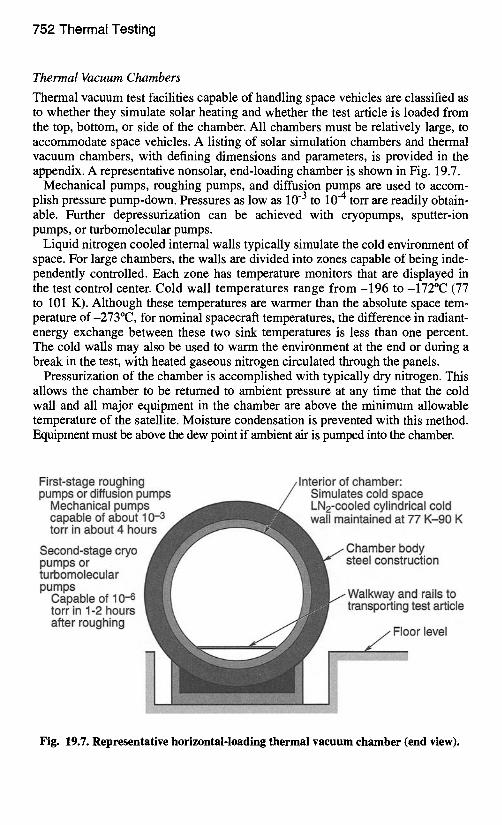
752 Thermal Testing
Thermal Vacuum Chambers
Thermal vacuum test facilities capable of handling space vehicles are classified as to whether they simulate solar heating and whether the test article is loaded from the top, bottom, or side of the chamber. All chambers must be relatively large, to accommodate space vehicles. A listing of solar simulation chambers and thermal vacuum chambers, with defining dimensions and parameters, is provided in the appendix. A representative nonsolar, end-loading chamber is shown in Fig. 19.7.
Mechanical pumps, roughing pumps, and diffusion pumps are used to accom- plish pressure pump-down. Pressures as low as 10 -3 to 10 -4 torr are readily obtain- able. Further depressurization can be achieved with cryopumps, sputter-ion pumps, or turbomolecular pumps.
Liquid nitrogen cooled internal walls typically simulate the cold environment of space. For large chambers, the walls are divided into zones capable of being inde- pendently controlled. Each zone has temperature monitors that are displayed in the test control center. Cold wall temperatures range f r o m - 1 9 6 to-172°C (77 to 101 K). Although these temperatures are warmer than the absolute space tem- perature of-273°C, for nominal spacecraft temperatures, the difference in radiant- energy exchange between these two sink temperatures is less than one percent. The cold walls may also be used to warm the environment at the end or during a break in the test, with heated gaseous nitrogen circulated through the panels.
Pressurization of the chamber is accomplished with typically dry nitrogen. This allows the chamber to be returned to ambient pressure at any time that the cold wall and all major equipment in the chamber are above the minimum allowable temperature of the satellite. Moisture condensation is prevented with this method. Equipment must be above the dew point if ambient air is pumped into the chamber.
First-stage roughing pumps or diffusion pumps
Mechanical pumps capable of about 10-3 torr in about 4 hours
Second-stage cryo pumps or turbomolecular pumps
Capable of 10 .-6 torr in 1-2 hours after roughing
Interior of chamber: Simulates cold space LN2-cooled cylindrical cold wall maintained at 77 K-90 K
Chamber body steel construction
Walkway and rails to transporting test article
Floor level
Fig. 19.7. Representative horizontal-loading thermal vacuum chamber (end view).
System Thermal Testing 753
All equipment associated with the vacuum or cryogenic operations of the cham- ber should be redundant or able to have its function assumed by other equipment in the event of a failure. Safety measures are critical to the operation of a chamber, and keeping the vehicle in a known state is important, should supply power, cool- ing capability, or instrumentation monitoring be interrupted.
Methods of Heating and Cooling
The specific method used to simulate the thermal environment within a vacuum chamber depends on the chamber characteristics, size and power levels of the test article, and the experience base of the test personnel. Radiative or conductive heat- ing is used. Cooling methods, for the most part, use the chamber cold wall as pre- viously described, but special cooling capabilities are used in the different heating schemes. Table 19.11 summarizes the following information about the techniques.
Three radiative methods of heating are common: solar simulation, heating ele- ments, and heater plates. Solar simulation heats the vehicle with solar-wavelength heaters that simulate the sun. A configuration such as that found in the JPL ther- mal chamber typifies the heating hardware. In this chamber, solar illumination is accomplished using an array of modules, each containing a 1-kW quartz-iodine lamp and a water-cooled collimator tube. The created spectrum approximates a 3000 K blackbody, so with the sun more nearly like a 5800 K blackbody, aug- menting xenon short-arc lamps are used to improve spectral matching. Solar simu- lation is the preferred method of spacecraft heating, because it allows the natural blockage and cavity effects to occur, while imposing direct and reflected solar- wavelength radiant heating. Vehicle-handling provisions are necessary to illumi- nate different sides of the spacecraft. These usually enable pitch and roll capabil- ity that can put the vehicle in motion under test.
Heating elements (such as heater lamps) are perhaps the most common method of heating spacecraft in a thermal chamber. They are not necessarily within the IR wavelength band, so lamp settings must be determined prior to the test to achieve the desired heat flux. They consist of individual radiant-heating units or tubes with a half-cylinder reflector. In heater wires, a similar heating method, consisting of an array of wires through which a current runs, heating is the result of the losses within the wire. The test setup requires many lamps, but each is controlled inde- pendently, so good flexibility can be achieved.
Heater plates of a known temperature and optical property can be positioned near spacecraft surfaces and can effectively warm the test item. When the plates are placed within inches of a surface, they closely control the environment. Cool- ing loops on the plates are required because the heater plates block the surface's view to the chamber cold wall. The use of plates is especially well suited for pay- load level tests, and they have also been used at the spacecraft level.
Two conductive methods of heating are common: the use of heaters and heater plates. The heaters technique, in which resistive heaters are mounted directly to spacecraft surfaces, offers minimal test equipment blockage and in many cases is used with specific hardware heating, such as appendages (booms, antennas, etc.) that may be difficult to heat with other methods. When used with a thermal blan- ket, heaters are mounted to the blanket's outermost layer. This usage requires test blankets identical to the flight blankets.
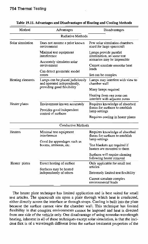
754 Thermal Testing
Table 19.11. Advantages and Disadvantages of Heating and Cooling Methods
Method Advantages Disadvantages
Radiative Methods
Solar simulation Does not assume a prior known environment
Minimal test equipment interference
Accurately simulates solar environment
Can detect geometric model errors
Few solar simulation chambers sized for large spacecraft
Lamps provide parallel illumination, so some test scenarios may be impossible
Cannot simulate nonsolar heat loads
Set can be complex
Heating elements Lamps can be placed judiciously Lamps may interfere with view to and operated independently, chamber wall providing good flexibility
Many lamps required
Heating from one zone can interfere with adjacent zones
Heater plates Environment known accurately
Provides good independent control of surfaces
Requires knowledge of absorbed fluxes for surfaces to establish lamp settings
Requires cooling in heater plates
Conductive Methods
Heaters Minimal test equipment interference
Good for appendages such as booms, antennas, etc.
Requires knowledge of absorbed fluxes for surfaces to establish lamp settings
Test blankets are required if heaters are mounted to them
Surfaces will require cleaning following heater removal
Heater plates Direct heating of surface
Surfaces may be heated independently of others
Only applicable for small test articles
Extremely limited test flexibility
Cannot simulate complex environmental loads
The heater plate technique has limited application and is best suited for small test articles. The spacecraft sits upon a plate through which heat is conducted, either directly across the interface or through straps. Cooling is built into the plate because the surface cannot view the chamber wall. This technique has limited flexibility in that complex environments cannot be imposed and heat is directed from one side of the vehicle only. One disadvantage of using nonsolar-wavelength heating, inherent in all of these techniques except solar simulation, is that the inci- dent flux is of a wavelength different from the surface treatment properties of the
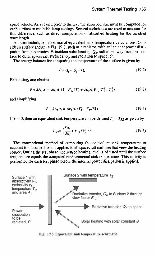
System Thermal Testing 755
space vehicle. As a result, prior to the test, the absorbed flux must be computed for each surface to establish lamp settings. Several techniques are used to account for this difference, such as direct computation of absorbed heating for the incident wavelength.
Another technique makes use of equivalent sink temperature calculations. Con- sider a surface shown in Fig. 19.8, such as a radiator, with an incident power dissi- pation from electronics, P, incident solar heating, Qs, radiation away from the sur- face to other spacecraft surfaces, Qi, and radiation to space, Qr
The energy balance for computing the temperature of the surface is given by
P + Qs = Qi + Qr. (19.2)
Expanding, one obtains
P + S A I ~ I = oE1AI(1-F12)T41 +~E1A1F12(T4-T4) (19.3)
and simplifying,
P + SAlal = t~EIAl(T41-F12T4). (19.4)
If P = 0, then an equivalent sink temperature can be defined T 1 = TES as given by
TES= \O, E1 + F12T4)l/4 (19.5)
The conventional method of computing the equivalent sink temperature to account for absorbed heat is applied to all spacecraft surfaces that view the heating source. During the test phase, the source heating level is adjusted until the surface temperature equals the computed environmental sink temperature. This activity is performed for each test phase before the internal power dissipation is applied.
Surface 1 with absorptivity ~1, emissivity el, temperature T1, and area A 1
Power dissipation to be radiated, P
Surface 2 with temperature T 2
~ R a d i a t i v e transfer, Qt~ to Surface 2 through J view factor F12
................................................................................................ ~ Radiative transfer, Qt~ to space
~ Solar heating with solar constant S
Fig. 19.8. Equivalent sink temperature schematic.
756 Thermal Testing
The surface temperature is monitored either with internal thermistors or, more commonly, heat flux calorimeters or radiometers.
Calorimeters and radiometers are thermocouples attached between two surfaces of controlled optical properties. Calorimeters attach to the spacecraft surface, and radiometers are typically suspended between the spacecraft surface and the heat source. In the case of a calorimeter, the control surface faces the heat source. The calorimeter is made of the same material as the spacecraft surface to which it attaches. The opposite side of the calorimeter consists of a small thermal blanket and a Velcro patch. The thermal blanket attaches to the thermocouple sensor plate on one side and supports the Velcro on the other. The Velcro mounts the calorime- ter to the spacecraft and, along with the thermal blanket, minimizes conduction and radiation between the calorimeter and the spacecraft. With this insulation between sensor plate and spacecraft, the thermocouple approximates the tempera- ture of the spacecraft surface, from which the absorbed heat can be computed.
Launch Site Thermal Testing Just as checkout and functional tests are performed throughout the stages of the development and buildup of the space vehicle, so they are also required at the launch site. Such tests are often part of the formal development, qualification, and acceptance process, in that they verify the flight hardware has not been damaged or degraded during shipment and assembly. They consist mainly of functional tests to verify continuity and baseline performance. The tests are rarely dedicated to verifying thermal requirements; rather, to ensure that subsystems do not over- heat in these tests, they include thermal control practices that typically involve gas or liquid cooling in an application such as maintaining battery temperatures.
Providing thermal control during tests may be difficult if adequate preparation has not been implemented with regard to the configuration of the subsystem or space vehicle in the launch configuration. Access to equipment panels or battery shelves is constrained by adjacent hardware (upper-stage vehicle, launch-vehicle payload fairing, acoustic blankets, etc.), such that making provisions for forced convection cooling may be difficult. The subsystem or space vehicle may be enveloped with contamination covers, shrouds, or the like, resulting in limited accessibility to forced convection cooling. Natural convection within the vehicle may result in heating of electronics in a manner different than expected in space. Finally, the subsystem or space vehicle may be oriented so that heat pipes are inoperative.
Early identification of launch site cooling requirements for checkout and func- tional tests is therefore imperative and is especially important for sensitive compo- nents such as batteries. Vehicle design accommodations and auxiliary ground equipment required to enable adequate cooling should be clearly specified. Items for this purpose may include ducting and fans, piping and pumps, and leveling hardware and instrumentation.
References 757
References 19.1. C. S. Tanner, "What's Happened to 1540?", Spacecraft Thermal Control Technol-
ogy Workshop, The Aerospace Corporation (1 March 2000).
19.2. R. D. Stark, "Thermal Testing of Spacecraft" The Aerospace Corp. Report No. TOR-0172(2441-01)-4 (September 1971).
19.3. R. W. Burrows, "Special Long-Life Assurance Studies, Long Life Assurance Stud- ies for Manned Spacecraft, Long Life Hardware," Martin Marietta Report No. MCR-72- 169, Vol. IV (September 1972).
19.4. C. E. Mandel, Environmental Stress Screening Guidelines for Assemblies, Institute of Environmental Sciences, September 1984.
19.5. Application Guidelines for MIL-STD-1540C; Test Requirements for Launch, Upper Stage and Space Vehicles, MIL-HDBK-340, 1 July 1985.
19.6. Department of Defense Handbook, Test Requirements for Launch, Upper Stage, and Space Vehicles, Volumes 1 and 2, MIL-STD-340A (USAF), 1 April 1999.
19.7. Department of Defense Standard Practice, Product Verification Requirements for Launch, Upper Stage, and Space Vehicles, MIL-STD-1540D, 15 January 1999.
19.8. NASA Preferred Reliability Practices, Practice No. PT-TE-1402, Thermal Cycling, Lewis Research Center.
19.9. NASA Preferred Reliability Practices, Practice No. PT-TE-1404, Thermal Test Lev- els and Duration, Jet Propulsion Laboratory.
19.10. A. H. Quintero, J. W. Welch, and H. Wolf, "Perceptiveness of Thermal Vacuum Testing," 18th Aerospace Testing Seminar, 16-18 March 1999.
19.11. Risk/Requirements Trade-off Guidelines for Faster, Better, Cheaper Missions, Jet Propulsion Laboratory, JPL D-13277, Rev. E (February 1998).
19.12. Test Requirements for Launch, Upper-Stage, and Space Vehicles, Military Stan- dard, MIL-STD- 1540C, 15 September 1994.
19.13. J. W. Welch, "Unit Thermal Vacuum Test Consideration" Spacecraft Thermal Control Technology Workshop, The Aerospace Corporation (28 February 2001).