Embed Size (px)
Citation preview
A A CompactCompact RepetitiveRepetitive HighHigh PowerPowerMicrowaveMicrowave (HPM)(HPM) SourceSource
V.G.BaryshevskyV.G.Baryshevsky**††, , A.E.BorisevichA.E.Borisevich**††, , A.A.GurinovichA.A.Gurinovich**††, , G.Yu.DrobychevG.Yu.Drobychev*, *, A.V.SenkoA.V.Senko**
*Research Institute for Nuclear Problems† Private Research and Production Company «Electrophysical Laboratory», Minsk, Belarus
ANTEM / AMEREM July 5-9, 2010 Ottawa, Canada
Introduction
An HPM source generates short high-power electromagnetic pulses able to disrupt or destroy electrical and electronic systems our society is rapidly becoming more and more dependent on. The infrastructure vulnerability (computers, electronics of a car, communication systems, etc.) is suspected, but is not definitely known. Simulators and test facilities for evaluating the HPM effect on electronics could provide the missing data and enable one to explore the protective measures. A range of HPM sources from small autonomous systems to large high power devices have been developed.
Outline
Marx generator designAntenna designExperimentsConclusions
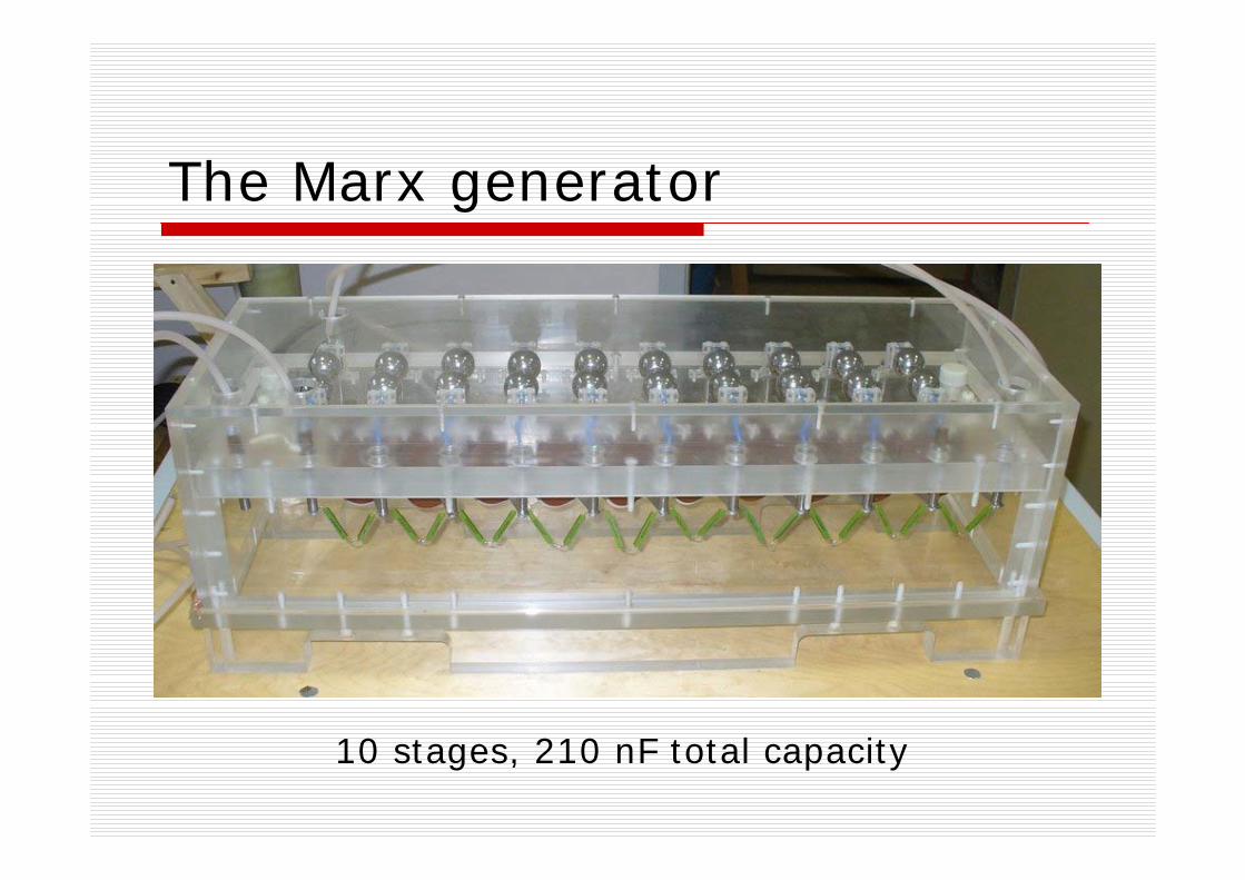
The Marx generator
10 stages, 210 nF total capacity
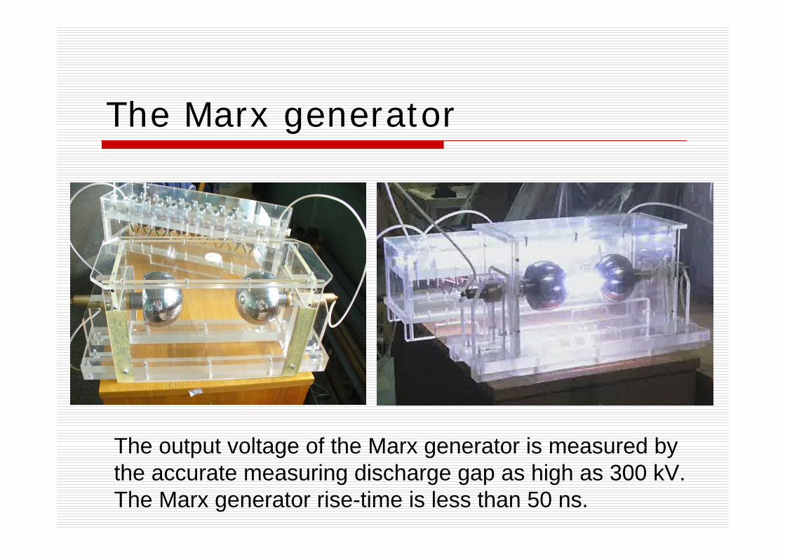
The Marx generator
The output voltage of the Marx generator is measured by the accurate measuring discharge gap as high as 300 kV. The Marx generator rise-time is less than 50 ns.
Antenna design
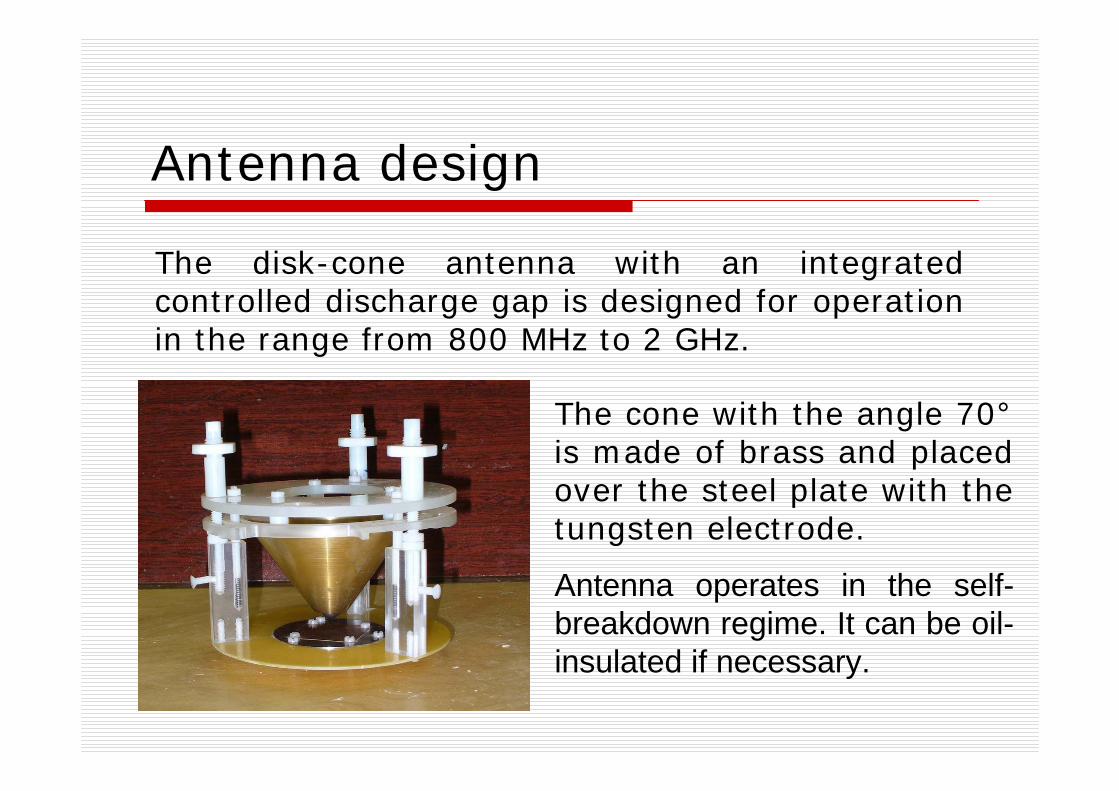
The disk-cone antenna with an integrated controlled discharge gap is designed for operation in the range from 800 MHz to 2 GHz.
The cone with the angle 70°is made of brass and placed over the steel plate with the tungsten electrode.
Antenna operates in the self-breakdown regime. It can be oil-insulated if necessary.
Antenna design
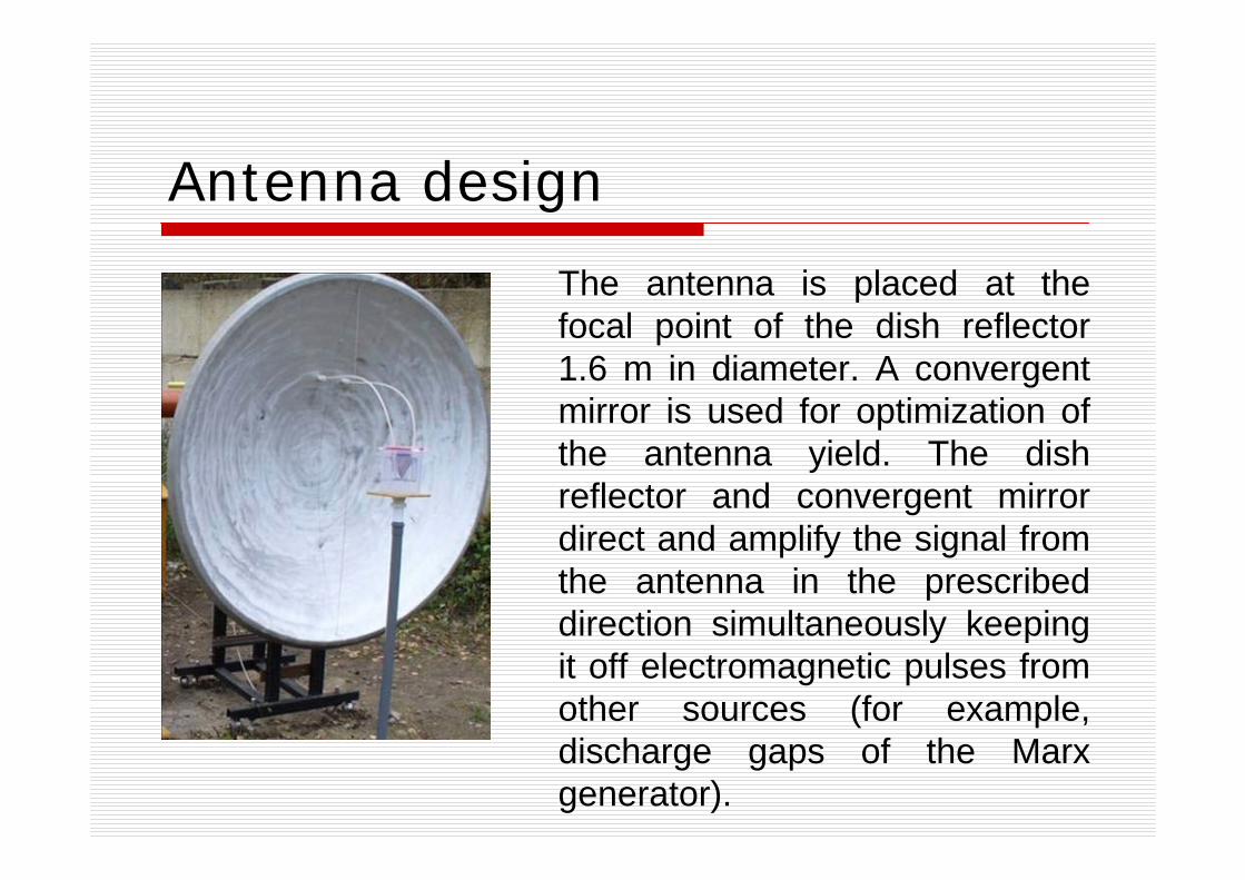
The antenna is placed at the focal point of the dish reflector 1.6 m in diameter. A convergent mirror is used for optimization of the antenna yield. The dish reflector and convergent mirror direct and amplify the signal from the antenna in the prescribed direction simultaneously keeping it off electromagnetic pulses from other sources (for example, discharge gaps of the Marx generator).
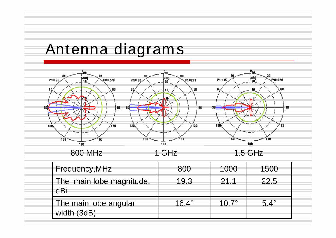
Antenna diagrams
1.5 GHz800 MHz 1 GHz
5.4°10.7°16.4°The main lobe angular width (3dB)
22.521.119.3The main lobe magnitude, dBi
15001000800Frequency,MHz
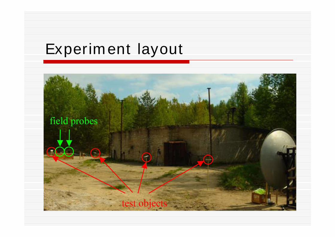
Experiment layout
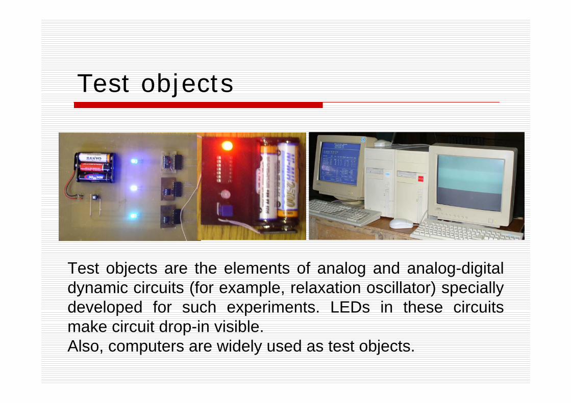
Test objects
Test objects are the elements of analog and analog-digital dynamic circuits (for example, relaxation oscillator) specially developed for such experiments. LEDs in these circuits make circuit drop-in visible. Also, computers are widely used as test objects.
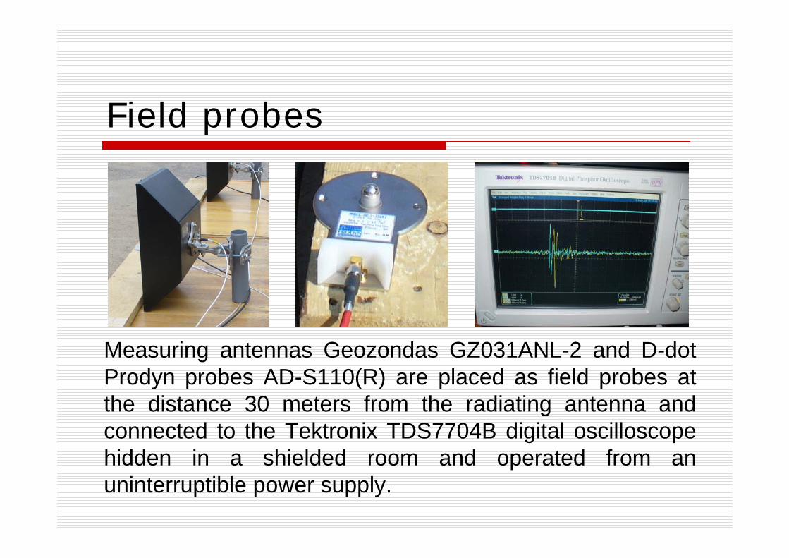
Field probes
Measuring antennas Geozondas GZ031ANL-2 and D-dot Prodyn probes AD-S110(R) are placed as field probes at the distance 30 meters from the radiating antenna and connected to the Tektronix TDS7704B digital oscilloscope hidden in a shielded room and operated from an uninterruptible power supply.
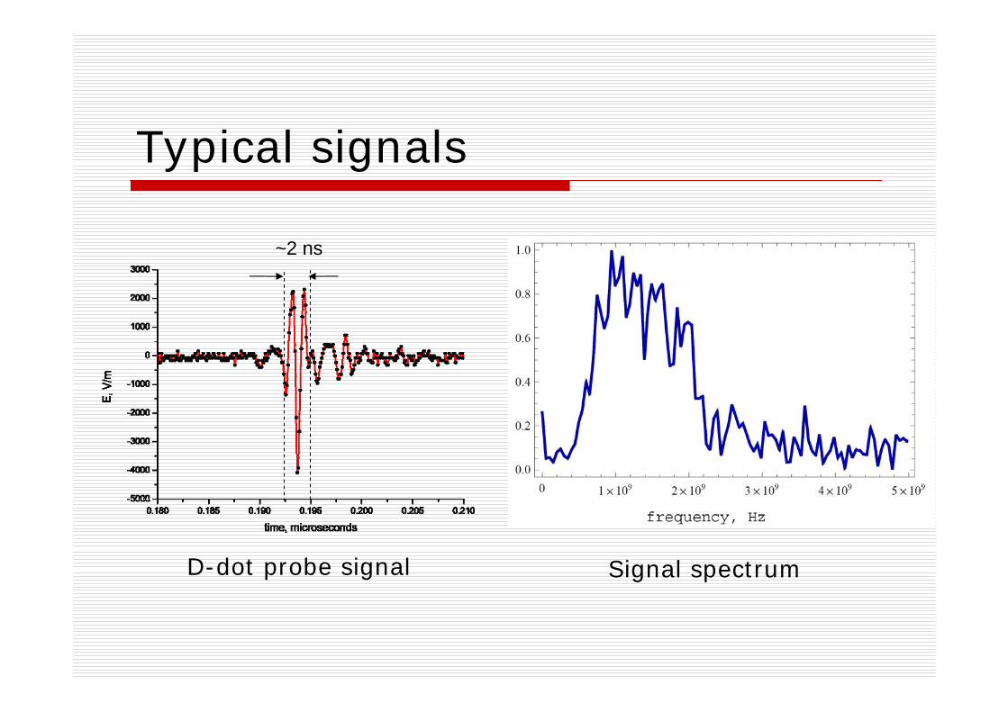
Typical signals
~2 ns
D-dot probe signal Signal spectrum
Experiment results
As the discharge gaps of the Marx generator operate in air the amplitude of the signal depends on the environmental conditions (humidity, dust and so on) and varies from 6.5kV/m to 3kV/m at a distance of 30 meters from the antenna in different tests. Placing test objects at different distances from the antenna makes it possible to test them with different electric field strength.
Different damage effects are detected for desktop computers: stopping (the clock in BIOS stops, operation restores after reload), graphics card malfunction (operation restores in several hours)
Summary
The developed HPM source is compact and easy-to-use. It allows one to test different electronic components and devices for HPM effect both in the laboratory and at the testing area simulating diverse cases of interest in the wide range of electric field strength in the frequency range from 800 MHz to 2 GHz.
Thank you for your attention


![Dokumentacja techniczna Liebert HPM - klimatLiebert HPM–PD–273492 – 20.04.2012:VWÚS Liebert HPM 8U]ÈG]HQLH Liebert HPM WR QRZD VHULD NOLPDW\]DWRUöZ VWZRU]RQ\FK SU]H] UPÚ](https://img.pdfslide.net/doc/110x75/60f7c1924ff57d411a1885fb/dokumentacja-techniczna-liebert-hpm-liebert-hpmapda273492-a-20042012vws.jpg)